US7546214B2 - System for power sub-metering - Google Patents
System for power sub-meteringDownload PDFInfo
- Publication number
- US7546214B2 US7546214B2US11/760,322US76032207AUS7546214B2US 7546214 B2US7546214 B2US 7546214B2US 76032207 AUS76032207 AUS 76032207AUS 7546214 B2US7546214 B2US 7546214B2
- Authority
- US
- United States
- Prior art keywords
- hub
- circuit
- voltage
- circuit breaker
- power consumption
- Prior art date
- Legal status (The legal status is an assumption and is not a legal conclusion. Google has not performed a legal analysis and makes no representation as to the accuracy of the status listed.)
- Active
Links
- 238000004891communicationMethods0.000claimsabstractdescription75
- 239000004020conductorSubstances0.000claimsabstractdescription21
- 238000012545processingMethods0.000claimsdescription9
- 238000005070samplingMethods0.000claimsdescription6
- 238000005259measurementMethods0.000description8
- 238000000034methodMethods0.000description8
- 238000009434installationMethods0.000description3
- 230000005355Hall effectEffects0.000description1
- 230000003213activating effectEffects0.000description1
- 230000005540biological transmissionEffects0.000description1
- 230000003831deregulationEffects0.000description1
- 238000013461designMethods0.000description1
- 238000010586diagramMethods0.000description1
- 230000000694effectsEffects0.000description1
- 238000005265energy consumptionMethods0.000description1
- 230000020169heat generationEffects0.000description1
- 238000011900installation processMethods0.000description1
- 230000010354integrationEffects0.000description1
- 238000004519manufacturing processMethods0.000description1
- 239000000463materialSubstances0.000description1
- 238000012986modificationMethods0.000description1
- 230000004048modificationEffects0.000description1
- 230000007935neutral effectEffects0.000description1
- 230000001360synchronised effectEffects0.000description1
- 230000001131transforming effectEffects0.000description1
- 238000009423ventilationMethods0.000description1
Images


Classifications
- G—PHYSICS
- G01—MEASURING; TESTING
- G01R—MEASURING ELECTRIC VARIABLES; MEASURING MAGNETIC VARIABLES
- G01R22/00—Arrangements for measuring time integral of electric power or current, e.g. electricity meters
- G01R22/06—Arrangements for measuring time integral of electric power or current, e.g. electricity meters by electronic methods
- G01R22/061—Details of electronic electricity meters
- G01R22/063—Details of electronic electricity meters related to remote communication
- G—PHYSICS
- G01—MEASURING; TESTING
- G01R—MEASURING ELECTRIC VARIABLES; MEASURING MAGNETIC VARIABLES
- G01R22/00—Arrangements for measuring time integral of electric power or current, e.g. electricity meters
- G—PHYSICS
- G01—MEASURING; TESTING
- G01R—MEASURING ELECTRIC VARIABLES; MEASURING MAGNETIC VARIABLES
- G01R22/00—Arrangements for measuring time integral of electric power or current, e.g. electricity meters
- G01R22/06—Arrangements for measuring time integral of electric power or current, e.g. electricity meters by electronic methods
- G01R22/10—Arrangements for measuring time integral of electric power or current, e.g. electricity meters by electronic methods using digital techniques
Definitions
- the present disclosurerelates generally to electrical power distribution, and particularly to measurement of power for at least one of a plurality of circuits.
- a building owner of a multi-tenant buildingwhere deregulation has taken effect, can often purchase power from a utility provider in bulk at a wholesale rate, and re-sell it to the tenants.
- a sub-metering panelallows the building owner to accurately measure & bill the tenants for the power consumed by each tenant.
- CTcurrent transformer
- Modular meteringinvolves installing a modular meter for each suite. This method is space consuming, as it requires a meter for each circuit to be monitored.
- Yet another method of sub-meteringis also known as master metering. In this method of sub-metering, a building owner divides the total annual utility bill of the building by a predetermined factor, such as square footage, and number of tenants per suite, for example, and charges the suite's tenant a fraction of the total utility bill according to the predetermined factor. This method is highly inaccurate.
- An embodiment of the inventionincludes an electrical sub-metering system for making available information associated with power consumption of at least one circuit of a plurality of circuits.
- the systemincludes an electrical panel board configured to distribute power to the plurality of circuits, a circuit breaker in power connection with a conductor of the at least one circuit, a voltage sensor, a hub to collect the information associated with power consumption from the voltage sensor and the circuit breaker, and a data collector to collect and make available to a user the information associated with power consumption.
- the circuit breakerincludes a current measuring device to measure current through the at least one circuit and is in signal communication with the hub via a single communication interface that has a plurality of communication paths
- Another embodiment of the inventionincludes an electrical sub-metering system for making available information associated with power consumption of at least one circuit of a plurality of circuits.
- the systemincludes an electrical panel board to distribute power to the plurality of circuits, a circuit breaker including a micro-electromechanical system (MEMS) based current sensor, the circuit breaker in power connection with a conductor of the at least one circuit, a voltage sensor, a hub to collect the information associated with power consumption from the circuit breaker and the voltage sensor, and a data collector to collect and make available to a user the information associated with power consumption for the at least one circuit.
- MEMSmicro-electromechanical system
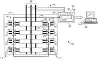
- FIG. 1depicts a schematic block diagram of an electrical sub-metering system in accordance with an embodiment of the invention
- FIG. 2depicts a schematic representation of an exemplary current sensing module in accordance with an embodiment of the invention
- FIG. 3depicts a schematic representation of an exemplary communication link in accordance with an embodiment of the invention
- FIG. 4depicts a top perspective view of an exemplary circuit breaker in accordance with an embodiment of the invention.
- FIG. 5depicts a pictorial schematic representation of a connection between a plurality of hubs and a data collector in accordance with an embodiment of the invention.
- An embodiment of the inventionwill provide a compact sub-metering panel that will accurately track and store the power consumption of each suite, or apartment, in a multi-tenant building. Measurements of voltage and current of each suite will be used to calculate the power consumed by the suite.
- the compact sub-metering panelwill measure the current using a MEMS-based current sensor proximate to a conductor of each sub-metered breaker, and transmit the measurement to a panel-centralized hub.
- one of the hub, and a module including the current sensorwill measure the voltage, calculate the energy and power consumed by each breaker, and output the energy and power consumption calculations to a central data collector.
- the modulemay be integrated within each sub-metered breaker.
- the data collectorwill calculate a bill, based on the energy and power consumed by the particular suite.
- the transmission from the hub to data collectorcan be one of a wired connection and a wireless connection.
- the sub-metering system 100comprises an electrical panel board (also herein referred to as a panel) 115 , a plurality 111 of circuits 110 , a plurality 131 of current sensing modules (CSMs) (also herein referred to as “current measuring devices” or “modules”) 130 , a hub 120 , and a data collector 150 .
- each CSM 130 of the plurality 131 of CSMs 130is associated with a respective one circuit 110 of the plurality 111 of circuits.
- the electrical sub-metering system 100is configured to make available to a user a power consumption calculation of at least one circuit 110 of the plurality 111 of circuits.
- the term usershall refer to any person or group of persons such as a tenant, a property manager, a property management association, a utility company, and a corporate consumer of power, for example, that may be interested to be aware of the specific amount of power consumed by the specific circuit 110 .
- the amount of power consumed by the specific circuit 110 , or a group of specific circuits 110may represent the amount of power that has been consumed, such as by a specific tenant, or a specific department within a corporate setting.
- suiteshall refer to an apartment within an multi-tenant building, an office within an office building, a department within a facility, or any other sub-group of circuits that may be desired to be segregated from the entire group for the purposes of measurement and tracking of power consumption.
- the electrical panel board 115is configured to distribute power from a common source, or feed 105 to the plurality 111 of circuits 110 , each circuit 110 capable of identification as representing a unique point of power consumption, as described above.
- the CSM 130is configured to measure, or monitor, the current flow through each circuit 110 of the plurality 111 of circuits. It will be appreciated that while an embodiment of the invention has been depicted having the CSM 130 in connection with all circuits 110 of the plurality 111 of circuits 110 ′, that the scope of the invention will not be so limited, and that the invention will also apply to sub-metering systems 100 that may have the CSM 130 in connection with any portion of the plurality 111 of circuits 110 .
- the hub 120is in signal communication with the plurality 131 of CSMs 130 via a single communication interface 140 (also herein referred to as a “communication link”), and the electrical panel board 115 via feed 105 connections 141 .
- the hub 120includes processing circuitry 125 for calculating, transforming, and communicating the information associated with the power consumption.
- the hub 120is configured to collect information associated with power consumption from the CSM 130 and the panel 115 .
- the data collector 150is in signal communication with the hub 120 , which is configured to collect and to make available to the user the power consumption calculation derived from the information associated with power consumption for each circuit 110 that is in connection with the CSM 130 .
- the hub 120includes a voltage sensor 123 configured to measure the voltage of each circuit 110 . It will be appreciated that the voltage sensor 123 may be one of many types known in the art, such as a resistive bridge network configured to measure voltage, for example.
- the CSM 130includes a micro-electromechanical system (MEMS)-based current sensor, as described in commonly assigned U.S. Patent Application Publication No. 2005/0270014 entitled “Micro-Electromechanical System (MEMS) Based Current & Magnetic Field Sensor Having Capacitive Sense Components”, and U.S. Patent Application Publication No. 2005/0248340 entitled “Microelectromechanical System Sensor and Method for Using”, the contents of which are herein incorporated by reference in their entirety.
- MEMSmicro-electromechanical system
- a circuit breaker 114is in power connection with a conducting cable (also herein referred to as a conductor) 112 , 113 of the circuit 110 , and disposed within the panel 115 .
- a conducting cablealso herein referred to as a conductor
- current sensors 205are depicted disposed within the CSM 130 .
- the CSM 130includes the current sensors 205 and their appropriate interface electronics 206 .
- the interface electronics 206 of the CSM 130are configured to amplify, sample, and process a sensed, or measured, current flow, and include communication circuitry to male available to the hub 120 a signal representative of the sensed current flow.
- the interface electronics 206are configured to be receptive of a signal representative of the circuit 110 voltage, to calculate the power consumed, and to make available, via the communication circuitry of the interface electronics 206 , to the hub 120 the power consumption calculation.
- the CSM 130is a modular design having a two-piece housing 220 , 221 to allow the current sensors 205 of the CSM 130 to be installed without the need to remove the conductor 112 , 113 from the breaker 114 , or any other connection made with the conductor 112 , 113 .
- the MEMS-based current sensor 205is disposed proximate a portion less than 100% of a circumference of the conductor 112 , 113 of one of the plurality 111 of circuits 110 , absent complete enclosure of the conductor 112 , 113 .
- the MEMS-based current sensor 205is disposed proximate the circuit breaker 114 .
- the CSM 130additionally includes a voltage sensor 124 , such as a resistive bridge network configured to measure voltage, for example.
- the MEMS-based current sensor 205is clipped onto the conductor 112 , 113 , allowing an installer a simple means to retrofit panels 115 that were not originally configured to provide sub-metering functionality. While the clip of the current sensor 205 may completely encircle or enclose the conductor 112 , 113 , as previously discussed, the actual MEMS-based current sensor 205 is disposed proximate a portion less than 100% of the circumference of the conductor 112 , 113 , absent complete enclosure of the conductor 112 , 113 . In an embodiment, the current sensor 205 is attached, or clipped, onto the conductor 112 , 113 absent a split-core transformer, as may be used in other sub-metering applications. In an embodiment, the MEMS-based current sensor 205 provides current measurements having enhanced accuracy over split-core current transformers.
- the information associated with power consumptionare to be transmitted via wired communications from the CSM 130 to the hub 120 .
- multiple CSMs 130are linked together, in series, to the hub 120 by a connection arrangement referred to as a daisy-chain connection.
- each of the plurality 131 of CSMs 130further comprises an address switch 210 in signal communication with identification circuitry 211 for identifying the CSM 130 associated with the information associated with power consumption of the respective circuit 110 through which the measured current flows.
- the CSM 130shall have a LED 215 , to indicate operation status of the CSM 130 , and a cable port 230 for interconnection with other CSMs 130 and the hub 120 .
- the CSM 130includes more than one cable port 230 .
- the address switch 210allows an installer of the CSM 130 to set, or define, the address of each CSM 130 to identify the current measurements that relate to each circuit, and ultimately, each sub-metered suite.
- the address of the CSM 130which correlates the sub-metered circuit 110 to the sub-metered suite, is set by the installer and transmitted with the signals representative of the measured current flow.
- the plurality 131 of the CSMs 130is in signal communication with the hub 120 via the single communication link 140 .
- the single communication link 140has a plurality of communication paths 305 , or conductors.
- the single communication link 140is a wire that comprises a single connector 310 at each end thereof configured to connect the plurality of communication paths 305 to the hub 120 at one end of the link 140 and the CSM 130 at the other end of the link 140 .
- the single connector 310is an RJ45 type of connector that is often used to provide computer-networking connections. Use of the single connector 310 allows for simple and time efficient connections between the plurality 131 of CSMs 130 and the hub 120 .
- each CSM 130 of the plurality 131 of CSMs 130are associated with a respective one circuit 110 of the plurality 111 of circuits.
- the single communication link 140is configured to provide to the hub 120 the information associated with the power consumption calculation for the plurality 131 of the CSMs 130 .
- the information associated with the power consumption calculationis identified by circuit 110 via the address switch 210 .
- each CSM 130 of the plurality 131is in signal communication with at least one other CSM 130 of the plurality 131 of CSMs 130 .
- the CSM 130includes a wireless communication device 240
- the hub 120includes a wireless communication device 122
- the hub 120is in signal communication with the CSM 130 via a wireless connection provided by the wireless communication devices 240 , 122 .
- the voltageis measured across a set of bus bars of the power feed 105 in the panel 115 , and referenced to neutral via the voltage sensor 123 .
- the current and voltage measurementsare synchronized via a communication protocol or synchronization pulse.
- the measured current and voltage of the circuit 110is used to perform the energy and power consumption calculations corresponding to the circuit 110 .
- the hub 120may also include a display screen 121 , to allow the user to view one of stored and real-time data, per suite.
- the display screen 121 of the hub 120may be used to display and define the addresses of the CSMs 130 .
- the hub 120is disposed within the panel 115 . In another embodiment, the hub 120 is attached to the panel 115 .
- one of the energy consumption calculation and the power consumption calculationis transmitted from the hub 120 to the data collector 150 .
- the data collector 150is configured to utilize the transmitted consumption calculations to determine the energy bill per suite.
- billing-tracking softwarecorrelates each power consumption value with the particular suite, at particular rates, which may be set by the utility, building owner, or billing company. In an embodiment, this billing information can be transmitted via one of wired and wireless communication to the building owner, or billing company.
- the data collectorcan also operate as a part of a Supervisory Control And Data Acquisition (SCADA) system, configured to monitor and control a variety of functions of a manufacturing site, for example.
- SCADASupervisory Control And Data Acquisition
- FIG. 4depicts an exemplary embodiment of a circuit breaker 450 into which the CSM 130 has been integrated.
- the same components of the CSM 130 described hereinare depicted with the same reference numerals in FIG. 4 and provide the same functionality.
- the circuit breaker 450(including the integrated CSM 130 ) transmits information associated with power consumption, including signals representative of the measured current from the circuit breaker 450 to the hub 120 via the communication interface 140 .
- multiple circuit breakers 450each associated with a respective one circuit 110 of the plurality circuits 111 depicted in FIG. 1 , are linked together in series to the hub 120 by a connection arrangement referred to as a daisy-chain connection.
- the current sensors 205may be MEMS-based current sensor 205 disposed proximate the conductor 112 , 113 of one of the plurality 111 of circuits 110 , absent complete enclosure of the conductor 112 , 113 .
- Use of MEMS-based current sensors 205 within the circuit breaker 450provide an accuracy and communication capability suitable for sub-metering purposes.
- use of MEMS-based current sensors 205allow integration of the CSM 130 into the circuit breaker 450 without an increase in external envelope dimensions of the circuit breaker 450 when compared to a circuit breaker of the same rating without the integrated CSM 130 .
- connection between a plurality of hubs 120 and the data collector 150is depicted.
- the connection between the hubs 120 and the data collector 150is provided by a network connection 410 via a network interface 405 , as depicted.
- the data collector 150is in signal communication with the hub 120 via the following types of network connection 410 : an Ethernet connection; a direct serial connection; a dial-up connection; and, a power line connection.
- the Ethernet connection 410includes one of an Internet connection, an Intranet connection, an Extranet connection, and a dial-up connection.
- the Ethernet connectionincludes one of a wired Ethernet connection and a wireless Ethernet connection.
- the network interface 405includes an Ethernet wireless router.
- the network interface 405comprises one of an Ethernet Hub, an Ethernet Switch, and an Ethernet Router.
- the network interface 405comprises a RS485/RS232 Converter.
- network interface 405includes at least one Ethernet to power line carrier bridge.
- the network interface 405includes a dial up to Ethernet gateway modem.
- embodiments of the sub-metering system 100are configured as follows.
- the hub 120is configured to provide to the CSM 130 the information associated with power consumption, including a signal representative of voltage of the circuit 110 corresponding with the measured current flow.
- the CSM 130further includes means, such as processing circuitry included with the interface electronics 206 for example, for performing the power consumption calculation using the information associated with power consumption provided by the hub 120 , and is configured to provide to the hub 120 the power consumption calculation.
- the hub 120is configured to provide to the CSM 130 a scaled voltage signal including a plurality of phases, such as a scaled three-phase voltage, for example, and the interface electronics 206 of the CSM 130 are configured to capture the scaled plurality of phases voltage signal.
- the hub 120is configured to synchronize sampling of current and voltage of each of the plurality 111 of circuits 110 , and to capture and provide to the CSM 130 , samples of the voltage of the circuit 110 corresponding with the measured current. In another embodiment, the hub 120 is configured to synchronize sampling of current and voltage of each of the plurality 111 of circuits 110 . The hub 120 is also configured to capture and transform samples of the voltage of the circuit 110 corresponding with the current measurement into a signal comprising voltage magnitude and phase, and to provide to the CSM 130 the signal comprising voltage magnitude and phase.
- the hub 120is configured to capture samples of voltage of the circuit 110 corresponding with the measured current.
- the hub 120is also configured to synchronize sampling of current and voltage of each of the plurality 111 of circuits 110 , and to request from the CSM 130 samples of the measured current corresponding with the captured samples of voltage.
- the CSM 130is configured to be responsive to the request from the hub 120 , and productive of the samples of the measured current corresponding to the captured samples of voltage to the hub 120 via the link 140 , and the hub 120 is configured to perform the power consumption calculation of the circuit 110 .
- the hub 120is configured to transform the captured samples of voltage of the circuit 110 into a signal comprising voltage magnitude and phase.
- the processing circuitry of the interface electronics 206 of the CSM 130is configured to be responsive to the request from the hub 120 , and productive of a signal representative of current magnitude and phase corresponding with the transformed samples of voltage.
- the CSM 130includes the voltage sensor 124 to capture samples of voltage of the circuit 110 corresponding with the measured current. Further, the processing circuit included with the interface electronics 206 performs the power consumption calculation and provides to the hub 120 the power consumption calculation via the power consumption calculation and provides to the hub 120 the power consumption calculation via the single communication link 140 .
- some embodiments of the inventionmay include some of the following advantages: the ability to reduce overall sub-metering panel dimensions as a result of the use of MEMS-based current sensors; the ability to increase sub-metering power calculation accuracy; the ability to increase installation ease of sub-metering functionality in existing systems lacking such functionality; the ability to reduce electrical panel ventilation requirements as a result of reduced heat generation by MEMS-based current sensors; and the ability to simplify sub-metering application installation by use of circuit breakers including CSMs to measure and communicate information associated with power consumption.
Landscapes
- Engineering & Computer Science (AREA)
- Power Engineering (AREA)
- Physics & Mathematics (AREA)
- General Physics & Mathematics (AREA)
- Remote Monitoring And Control Of Power-Distribution Networks (AREA)
- Arrangements For Transmission Of Measured Signals (AREA)
Abstract
Description
This application is a continuation-in-part application of U.S. application Ser. No. 11/536,377, filed Sep. 28, 2006, the contents of which are incorporated herein by reference in their entirety.
The present disclosure relates generally to electrical power distribution, and particularly to measurement of power for at least one of a plurality of circuits. A building owner of a multi-tenant building, where deregulation has taken effect, can often purchase power from a utility provider in bulk at a wholesale rate, and re-sell it to the tenants. A sub-metering panel allows the building owner to accurately measure & bill the tenants for the power consumed by each tenant.
Sub-metering is traditionally performed by installing a current transformer (CT) on the conductor that is carrying the electrical load. There is one CT per phase of any load that is to be monitored, and each CT has two wire leads that carry the signal from the CT to the meter. These CTs are space consuming and difficult to mount. They take up wire bend space within an electrical distribution enclosure, as defined by Underwriters Laboratories (UL), and are obstructions to wires and cables in the equipment gutters and wire ways. The installation of these CTs and the extensive internal wiring is a cumbersome, time-consuming process and therefore increases the expense associated with the installation process. Furthermore, while present CTs incorporated within circuit breakers are adequate for their intended purpose of powering and activating circuit breaker trip units, they typically lack an accuracy and external communication capability suitable for sub-metering purposes.
Another method of sub-metering is also known as modular metering. Modular metering involves installing a modular meter for each suite. This method is space consuming, as it requires a meter for each circuit to be monitored. Yet another method of sub-metering is also known as master metering. In this method of sub-metering, a building owner divides the total annual utility bill of the building by a predetermined factor, such as square footage, and number of tenants per suite, for example, and charges the suite's tenant a fraction of the total utility bill according to the predetermined factor. This method is highly inaccurate.
Accordingly, there is a need in the art for a sub-metering arrangement that overcomes these drawbacks.
An embodiment of the invention includes an electrical sub-metering system for making available information associated with power consumption of at least one circuit of a plurality of circuits. The system includes an electrical panel board configured to distribute power to the plurality of circuits, a circuit breaker in power connection with a conductor of the at least one circuit, a voltage sensor, a hub to collect the information associated with power consumption from the voltage sensor and the circuit breaker, and a data collector to collect and make available to a user the information associated with power consumption. The circuit breaker includes a current measuring device to measure current through the at least one circuit and is in signal communication with the hub via a single communication interface that has a plurality of communication paths
Another embodiment of the invention includes an electrical sub-metering system for making available information associated with power consumption of at least one circuit of a plurality of circuits. The system includes an electrical panel board to distribute power to the plurality of circuits, a circuit breaker including a micro-electromechanical system (MEMS) based current sensor, the circuit breaker in power connection with a conductor of the at least one circuit, a voltage sensor, a hub to collect the information associated with power consumption from the circuit breaker and the voltage sensor, and a data collector to collect and make available to a user the information associated with power consumption for the at least one circuit.
Referring to the exemplary drawings wherein like elements are numbered alike in the accompanying Figures:
An embodiment of the invention will provide a compact sub-metering panel that will accurately track and store the power consumption of each suite, or apartment, in a multi-tenant building. Measurements of voltage and current of each suite will be used to calculate the power consumed by the suite. In an embodiment, the compact sub-metering panel will measure the current using a MEMS-based current sensor proximate to a conductor of each sub-metered breaker, and transmit the measurement to a panel-centralized hub. In an embodiment, one of the hub, and a module including the current sensor will measure the voltage, calculate the energy and power consumed by each breaker, and output the energy and power consumption calculations to a central data collector. The module may be integrated within each sub-metered breaker. In an embodiment, the data collector will calculate a bill, based on the energy and power consumed by the particular suite. In an embodiment, the transmission from the hub to data collector can be one of a wired connection and a wireless connection.
Referring now toFIG. 1 , anelectrical sub-metering system 100 is depicted. In an embodiment, thesub-metering system 100 comprises an electrical panel board (also herein referred to as a panel)115, aplurality 111 ofcircuits 110, aplurality 131 of current sensing modules (CSMs) (also herein referred to as “current measuring devices” or “modules”)130, ahub 120, and adata collector 150. In an embodiment, eachCSM 130 of theplurality 131 ofCSMs 130 is associated with a respective onecircuit 110 of theplurality 111 of circuits.
In an embodiment, theelectrical sub-metering system 100 is configured to make available to a user a power consumption calculation of at least onecircuit 110 of theplurality 111 of circuits. As used herein, the term user shall refer to any person or group of persons such as a tenant, a property manager, a property management association, a utility company, and a corporate consumer of power, for example, that may be interested to be aware of the specific amount of power consumed by thespecific circuit 110. In an embodiment, the amount of power consumed by thespecific circuit 110, or a group ofspecific circuits 110, may represent the amount of power that has been consumed, such as by a specific tenant, or a specific department within a corporate setting. As used herein, the term suite shall refer to an apartment within an multi-tenant building, an office within an office building, a department within a facility, or any other sub-group of circuits that may be desired to be segregated from the entire group for the purposes of measurement and tracking of power consumption.
In an embodiment, theelectrical panel board 115 is configured to distribute power from a common source, or feed105 to theplurality 111 ofcircuits 110, eachcircuit 110 capable of identification as representing a unique point of power consumption, as described above. In an embodiment, the CSM130 is configured to measure, or monitor, the current flow through eachcircuit 110 of theplurality 111 of circuits. It will be appreciated that while an embodiment of the invention has been depicted having theCSM 130 in connection with allcircuits 110 of theplurality 111 ofcircuits 110′, that the scope of the invention will not be so limited, and that the invention will also apply tosub-metering systems 100 that may have theCSM 130 in connection with any portion of theplurality 111 ofcircuits 110.
In an embodiment, thehub 120 is in signal communication with theplurality 131 ofCSMs 130 via a single communication interface140 (also herein referred to as a “communication link”), and theelectrical panel board 115 viafeed 105connections 141. Thehub 120 includesprocessing circuitry 125 for calculating, transforming, and communicating the information associated with the power consumption. In an embodiment, thehub 120 is configured to collect information associated with power consumption from the CSM130 and thepanel 115. In an embodiment, thedata collector 150 is in signal communication with thehub 120, which is configured to collect and to make available to the user the power consumption calculation derived from the information associated with power consumption for eachcircuit 110 that is in connection with the CSM130. In an embodiment, thehub 120 includes avoltage sensor 123 configured to measure the voltage of eachcircuit 110. It will be appreciated that thevoltage sensor 123 may be one of many types known in the art, such as a resistive bridge network configured to measure voltage, for example.
While an embodiment of the invention has been described and depicted with onehub 120 in signal communication with thedata collector 150, it will be appreciated that the scope of the invention is not so limited, and that the invention will also apply toelectrical sub-metering systems 100 that may include alternate arrangements of the hub and the data collector, such as having more than one hub in signal communication with a single data collector, one hub in signal communication with more than one data collector, and more than one hub in signal communication with more than one data collector, for example. Further, while an embodiment has been depicted with one CSM in signal communication with the hub, it will be appreciated that the scope of the invention is not so limited, and that the invention will also apply toelectrical sub-metering systems 100 that may have alternate arrangements of the CSM and the hub, such as more than one CSM in signal communication with one hub, for example.
In an embodiment, the CSM130 includes a micro-electromechanical system (MEMS)-based current sensor, as described in commonly assigned U.S. Patent Application Publication No. 2005/0270014 entitled “Micro-Electromechanical System (MEMS) Based Current & Magnetic Field Sensor Having Capacitive Sense Components”, and U.S. Patent Application Publication No. 2005/0248340 entitled “Microelectromechanical System Sensor and Method for Using”, the contents of which are herein incorporated by reference in their entirety.
While an embodiment of the invention has been described having a current sensing module including a MEMS-based current sensor, it will be appreciated that the scope of the invention is not so limited, and that the invention will also apply toelectrical sub-metering systems 100 using CSMs having alternate current sensors, such as hall-effect current sensors, for example.
With reference now toFIGS. 1 and 2 , an exemplary embodiment of the CSM130 is depicted. In an embodiment, acircuit breaker 114 is in power connection with a conducting cable (also herein referred to as a conductor)112,113 of thecircuit 110, and disposed within thepanel 115. In the embodiment depicted inFIG. 2 ,current sensors 205 are depicted disposed within theCSM 130. In an embodiment, the CSM130 includes thecurrent sensors 205 and theirappropriate interface electronics 206. In an embodiment, theinterface electronics 206 of theCSM 130 are configured to amplify, sample, and process a sensed, or measured, current flow, and include communication circuitry to male available to the hub120 a signal representative of the sensed current flow. In another embodiment, theinterface electronics 206 are configured to be receptive of a signal representative of thecircuit 110 voltage, to calculate the power consumed, and to make available, via the communication circuitry of theinterface electronics 206, to thehub 120 the power consumption calculation. In an embodiment, theCSM 130 is a modular design having a two-piece housing current sensors 205 of theCSM 130 to be installed without the need to remove theconductor breaker 114, or any other connection made with theconductor current sensor 205 is disposed proximate a portion less than 100% of a circumference of theconductor plurality 111 ofcircuits 110, absent complete enclosure of theconductor current sensor 205 is disposed proximate thecircuit breaker 114. In an embodiment, theCSM 130 additionally includes avoltage sensor 124, such as a resistive bridge network configured to measure voltage, for example.
In an embodiment, the MEMS-basedcurrent sensor 205 is clipped onto theconductor panels 115 that were not originally configured to provide sub-metering functionality. While the clip of thecurrent sensor 205 may completely encircle or enclose theconductor current sensor 205 is disposed proximate a portion less than 100% of the circumference of theconductor conductor current sensor 205 is attached, or clipped, onto theconductor current sensor 205 provides current measurements having enhanced accuracy over split-core current transformers.
In an embodiment, the information associated with power consumption, including signals representative of the measured current flows, are to be transmitted via wired communications from theCSM 130 to thehub 120. In an embodiment,multiple CSMs 130 are linked together, in series, to thehub 120 by a connection arrangement referred to as a daisy-chain connection. In an embodiment, each of theplurality 131 ofCSMs 130 further comprises anaddress switch 210 in signal communication with identification circuitry211 for identifying theCSM 130 associated with the information associated with power consumption of therespective circuit 110 through which the measured current flows. In an embodiment, theCSM 130 shall have aLED 215, to indicate operation status of theCSM 130, and acable port 230 for interconnection withother CSMs 130 and thehub 120. In an embodiment, theCSM 130 includes more than onecable port 230. In an embodiment, theaddress switch 210 allows an installer of theCSM 130 to set, or define, the address of eachCSM 130 to identify the current measurements that relate to each circuit, and ultimately, each sub-metered suite. In an embodiment, the address of theCSM 130, which correlates thesub-metered circuit 110 to the sub-metered suite, is set by the installer and transmitted with the signals representative of the measured current flow.
While an embodiment of the invention has been described and depicted having an address switch, it will be appreciated that the scope of the invention is not so limited, and that the invention will also apply to other means to identify the circuit through which the measured current flows, such as a dial, a pre-assigned serial number associated with the CSM, and a software-assigned identifier, such as an IP address that may be provided by one of the hub and the data collector, for example.
In an embodiment, theplurality 131 of theCSMs 130 is in signal communication with thehub 120 via thesingle communication link 140. Referring now toFIG. 3 , an exemplary embodiment of thesingle communication link 140 is depicted. In an embodiment, thesingle communication link 140 has a plurality ofcommunication paths 305, or conductors. In an embodiment, thesingle communication link 140 is a wire that comprises asingle connector 310 at each end thereof configured to connect the plurality ofcommunication paths 305 to thehub 120 at one end of thelink 140 and theCSM 130 at the other end of thelink 140. In an embodiment, thesingle connector 310 is an RJ45 type of connector that is often used to provide computer-networking connections. Use of thesingle connector 310 allows for simple and time efficient connections between theplurality 131 ofCSMs 130 and thehub 120.
While an embodiment of the invention has been described having an RJ45 connector, it will be appreciated that the scope of the invention is not so limited, and that the invention will also apply to electrical sub-metering systems having any other variety of multi-conductor connectors, such as RJ25 connectors, DE9 connectors, and Universal Serial Bus (USB) connectors, for example, to allow simple and time efficient connection between the CSMs and the hub.
In an embodiment, eachCSM 130 of theplurality 131 ofCSMs 130 are associated with a respective onecircuit 110 of theplurality 111 of circuits. In an embodiment, thesingle communication link 140 is configured to provide to thehub 120 the information associated with the power consumption calculation for theplurality 131 of theCSMs 130. In an embodiment, the information associated with the power consumption calculation is identified bycircuit 110 via theaddress switch 210. In an embodiment, eachCSM 130 of theplurality 131 is in signal communication with at least oneother CSM 130 of theplurality 131 ofCSMs 130.
While an embodiment of the invention has been depicted with the plurality of CSMs in signal communication with the hub via a single communication link, it will be appreciated that the scope of the invention is not so limited, and that the invention will also apply to electrical sub-metering systems having other communication link arrangements, such as two, three, four, or more, sets of CSMs, with each set in signal communication with the hub via the single communication link, and each CSM of each set in signal communication with at least one other CSM, for example.
In another embodiment, theCSM 130 includes awireless communication device 240, and thehub 120 includes awireless communication device 122. In an embodiment, thehub 120 is in signal communication with theCSM 130 via a wireless connection provided by thewireless communication devices
In an embodiment, the voltage is measured across a set of bus bars of thepower feed 105 in thepanel 115, and referenced to neutral via thevoltage sensor 123. In an embodiment, the current and voltage measurements are synchronized via a communication protocol or synchronization pulse. The measured current and voltage of thecircuit 110 is used to perform the energy and power consumption calculations corresponding to thecircuit 110. In an embodiment, thehub 120 may also include adisplay screen 121, to allow the user to view one of stored and real-time data, per suite. In another embodiment, thedisplay screen 121 of thehub 120 may be used to display and define the addresses of theCSMs 130. In an embodiment, thehub 120 is disposed within thepanel 115. In another embodiment, thehub 120 is attached to thepanel 115.
In an embodiment, one of the energy consumption calculation and the power consumption calculation is transmitted from thehub 120 to thedata collector 150. In an embodiment, thedata collector 150 is configured to utilize the transmitted consumption calculations to determine the energy bill per suite. In an embodiment, billing-tracking software correlates each power consumption value with the particular suite, at particular rates, which may be set by the utility, building owner, or billing company. In an embodiment, this billing information can be transmitted via one of wired and wireless communication to the building owner, or billing company. In an embodiment, the data collector can also operate as a part of a Supervisory Control And Data Acquisition (SCADA) system, configured to monitor and control a variety of functions of a manufacturing site, for example.
As described above, thecurrent sensors 205 may be MEMS-basedcurrent sensor 205 disposed proximate theconductor plurality 111 ofcircuits 110, absent complete enclosure of theconductor current sensors 205 within thecircuit breaker 450 provide an accuracy and communication capability suitable for sub-metering purposes. Furthermore, use of MEMS-basedcurrent sensors 205 allow integration of theCSM 130 into thecircuit breaker 450 without an increase in external envelope dimensions of thecircuit breaker 450 when compared to a circuit breaker of the same rating without theintegrated CSM 130.
Referring now toFIG. 5 , an exemplary embodiment of the connection between a plurality ofhubs 120 and thedata collector 150 is depicted. The connection between thehubs 120 and thedata collector 150 is provided by anetwork connection 410 via anetwork interface 405, as depicted. In an embodiment, thedata collector 150 is in signal communication with thehub 120 via the following types of network connection410: an Ethernet connection; a direct serial connection; a dial-up connection; and, a power line connection. In an embodiment, theEthernet connection 410 includes one of an Internet connection, an Intranet connection, an Extranet connection, and a dial-up connection. In an embodiment, the Ethernet connection includes one of a wired Ethernet connection and a wireless Ethernet connection. In an embodiment that provides awireless Ethernet connection 410, thenetwork interface 405 includes an Ethernet wireless router. In an embodiment that provides awired Ethernet connection 410, thenetwork interface 405 comprises one of an Ethernet Hub, an Ethernet Switch, and an Ethernet Router. In an embodiment that provides a directserial connection 410, thenetwork interface 405 comprises a RS485/RS232 Converter. In an embodiment that provides apower line connection 410,network interface 405 includes at least one Ethernet to power line carrier bridge. In an embodiment that provides a dial-upconnection 405, thenetwork interface 405 includes a dial up to Ethernet gateway modem.
In view of the foregoing, embodiments of thesub-metering system 100 are configured as follows.
In an embodiment, thehub 120 is configured to provide to theCSM 130 the information associated with power consumption, including a signal representative of voltage of thecircuit 110 corresponding with the measured current flow. TheCSM 130 further includes means, such as processing circuitry included with theinterface electronics 206 for example, for performing the power consumption calculation using the information associated with power consumption provided by thehub 120, and is configured to provide to thehub 120 the power consumption calculation. In an embodiment, thehub 120 is configured to provide to the CSM130 a scaled voltage signal including a plurality of phases, such as a scaled three-phase voltage, for example, and theinterface electronics 206 of theCSM 130 are configured to capture the scaled plurality of phases voltage signal. In another embodiment, thehub 120 is configured to synchronize sampling of current and voltage of each of theplurality 111 ofcircuits 110, and to capture and provide to theCSM 130, samples of the voltage of thecircuit 110 corresponding with the measured current. In another embodiment, thehub 120 is configured to synchronize sampling of current and voltage of each of theplurality 111 ofcircuits 110. Thehub 120 is also configured to capture and transform samples of the voltage of thecircuit 110 corresponding with the current measurement into a signal comprising voltage magnitude and phase, and to provide to theCSM 130 the signal comprising voltage magnitude and phase.
While an embodiment of the invention has been described having a voltage signal including a plurality of phases, such as three phases, it will be appreciated that the scope of the invention is not so limited, and that the invention will also apply to other sub-metering systems that may have other numbers of phases in a polyphase system, such as two, four, five, six, or more phases, as well as single phase systems, for example.
In another embodiment, thehub 120 is configured to capture samples of voltage of thecircuit 110 corresponding with the measured current. Thehub 120 is also configured to synchronize sampling of current and voltage of each of theplurality 111 ofcircuits 110, and to request from theCSM 130 samples of the measured current corresponding with the captured samples of voltage. TheCSM 130 is configured to be responsive to the request from thehub 120, and productive of the samples of the measured current corresponding to the captured samples of voltage to thehub 120 via thelink 140, and thehub 120 is configured to perform the power consumption calculation of thecircuit 110. In an embodiment, thehub 120 is configured to transform the captured samples of voltage of thecircuit 110 into a signal comprising voltage magnitude and phase. The processing circuitry of theinterface electronics 206 of theCSM 130 is configured to be responsive to the request from thehub 120, and productive of a signal representative of current magnitude and phase corresponding with the transformed samples of voltage.
In a further embodiment, theCSM 130 includes thevoltage sensor 124 to capture samples of voltage of thecircuit 110 corresponding with the measured current. Further, the processing circuit included with theinterface electronics 206 performs the power consumption calculation and provides to thehub 120 the power consumption calculation via the power consumption calculation and provides to thehub 120 the power consumption calculation via thesingle communication link 140.
As disclosed, some embodiments of the invention may include some of the following advantages: the ability to reduce overall sub-metering panel dimensions as a result of the use of MEMS-based current sensors; the ability to increase sub-metering power calculation accuracy; the ability to increase installation ease of sub-metering functionality in existing systems lacking such functionality; the ability to reduce electrical panel ventilation requirements as a result of reduced heat generation by MEMS-based current sensors; and the ability to simplify sub-metering application installation by use of circuit breakers including CSMs to measure and communicate information associated with power consumption.
While the invention has been described with reference to exemplary embodiments, it will be understood by those skilled in the art that various changes may be made and equivalents may be substituted for elements thereof without departing from the scope of the invention. In addition, many modifications may be made to adapt a particular situation or material to the teachings of the invention without departing from the essential scope thereof. Therefore, it is intended that the invention not be limited to the particular embodiment disclosed as the best or only mode contemplated for carrying out this invention, but that the invention will include all embodiments falling within the scope of the appended claims. Also, in the drawings and the description, there have been disclosed exemplary embodiments of the invention and, although specific terms may have been employed, they are unless otherwise stated used in a generic and descriptive sense only and not for purposes of limitation, the scope of the invention therefore not being so limited. Moreover, the use of the terms first, second, etc. do not denote any order or importance, but rather the terms first, second, etc. are used to distinguish one element from another. Furthermore, the use of the terms a, an, etc. do not denote a limitation of quantity, but rather denote the presence of at least one of the referenced item.
Claims (15)
1. An electrical sub-metering system for making available information associated with power consumption of at least one circuit of a plurality of circuits, the system comprising:
an electrical panel board configured to distribute power to the plurality of circuits;
at least one circuit breaker disposed within the electrical panel board, the at least one circuit breaker in power connection with a conductor of the at least one circuit, the at least one circuit breaker comprising a current measuring device configured to measure current through the at least one circuit;
a voltage sensor configured to measure voltage of each circuit of the plurality of circuits;
a hub in signal communication with the voltage sensor and the at least one circuit breaker, the hub configured to collect the information associated with power consumption from the voltage sensor and the at least one circuit breaker via the signal communication; and
a data collector in signal communication with the hub, the data collector configured to collect and make available to a user the information associated with power consumption for each circuit;
wherein the signal communication between the hub and the at least one circuit breaker is accomplished via a single communication interface, the single communication interface comprising a single communication link connected to the circuit breaker and the hub, the single communication link having a plurality of communication paths.
2. The system ofclaim 1 , wherein:
the at least one circuit breaker is part of a plurality of circuit breakers;
each of the plurality of circuits has associated therewith one of the plurality of circuit breakers; and
the plurality of circuit breakers is in signal communication with the hub via the single communication interface, each circuit breaker of the plurality of circuit breakers being in signal communication with at least one other of the plurality of circuit breakers via the single communication interface.
3. The system ofclaim 1 , wherein:
the current measuring device is disposed proximate a portion less than 100% of a circumference of a conductor of one circuit of the plurality of circuits.
4. The system ofclaim 1 , wherein:
the single communication link comprises a wire having a single connector at each end thereof the single connector configured to connect the plurality of communication paths to the hub at one end of the wire and to the at least one circuit breaker at the other end of the wire.
5. The system ofclaim 4 , wherein:
the single connector is an RJ45 connector.
6. The system ofclaim 1 , wherein:
the hub is configured to provide to the at least one circuit breaker via the single communication interface a signal representative of a voltage of the at least one circuit corresponding with the measured current;
the at least one circuit breaker further comprises processing circuitry for performing power consumption calculation using the information associated with power consumption; and
the at least one circuit breaker further comprises communication circuitry for communicating to the hub via the single communication interface the power consumption calculation.
7. The system ofclaim 1 , wherein:
the hub is configured to capture samples of a voltage of the at least one circuit corresponding with the measured current;
the hub is configured to synchronize sampling of current and voltage of the at least one circuit via the single communication interface, and to request from the at least one circuit breaker via the single communication interface samples of the measured current corresponding with the captured samples of voltage;
the at least one circuit breaker comprises processing circuitry responsive to the request from the hub, and productive of the samples of the measured current corresponding with the captured samples of voltage; and
the hub is configured to perform a power consumption calculation using the information associated with power consumption of the circuit.
8. The system ofclaim 1 , the at least one circuit breaker further comprising:
a voltage sensor configured to capture a sample of voltage of the at least one circuit corresponding with the measured current;
processing circuitry for performing a power consumption calculation using the information associated with power consumption; and
communication circuitry for communicating to the hub via the single communication interface the power consumption calculation.
9. The system ofclaim 1 , wherein:
the data collector is in signal communication with the hub via one of an Ethernet connection, a direct serial connection, a dial-up connection, and a power line connection.
10. The system ofclaim 6 , wherein:
the hub is configured to provide to the at least one circuit breaker via the single communication interface a scaled voltage signal comprising a plurality of phases; and
the processing circuitry captures the scaled voltage signal comprising the plurality of phases.
11. The system ofclaim 6 , wherein:
the hub is configured to synchronize sampling of current and voltage of each of the plurality of circuits via the single communication interface; and
the hub is configured to capture, and provide to the at least one circuit breaker via the single communication interface a sample of voltage of the at least one circuit corresponding with the measured current.
12. The system ofclaim 6 , wherein:
the hub is configured to synchronize sampling of current and voltage of each of the plurality of circuits via the single communication interface;
the hub is configured to capture and transform samples of the voltage of the at least one circuit corresponding with the measured current into a signal comprising voltage magnitude and phase; and
the hub is configured to provide to the at least one circuit breaker via the single communication interface the signal comprising voltage magnitude and phase.
13. The system ofclaim 7 , wherein:
the hub is configured to transform the captured samples of voltage of the at least one circuit into a signal comprising voltage magnitude and phase; and
the processing circuitry is responsive to the request from the hub, and productive of a signal representative of current magnitude and phase corresponding with the transformed samples of voltage.
14. The system ofclaim 9 , wherein:
the Ethernet connection comprises one of an Internet connection, an Intranet connection, an Extranet connection, and a dial-up connection; and
the Ethernet connection comprises one of a wired Ethernet connection and a wireless Ethernet connection.
15. The system ofclaim 1 , wherein: the current measuring device comprises a micro-electromechanical system (MEMS)-based current sensor.
Priority Applications (4)
| Application Number | Priority Date | Filing Date | Title |
|---|---|---|---|
| US11/760,322US7546214B2 (en) | 2006-09-28 | 2007-06-08 | System for power sub-metering |
| CN200780036386.XACN101523226B (en) | 2006-09-28 | 2007-06-20 | System for power sub-metering |
| KR1020097006385AKR20090057071A (en) | 2006-09-28 | 2007-06-20 | Electrical sub-metering system |
| PCT/US2007/071630WO2008042483A1 (en) | 2006-09-28 | 2007-06-20 | System for power sub-metering |
Applications Claiming Priority (2)
| Application Number | Priority Date | Filing Date | Title |
|---|---|---|---|
| US11/536,377US7493221B2 (en) | 2006-09-28 | 2006-09-28 | System for power sub-metering |
| US11/760,322US7546214B2 (en) | 2006-09-28 | 2007-06-08 | System for power sub-metering |
Related Parent Applications (1)
| Application Number | Title | Priority Date | Filing Date |
|---|---|---|---|
| US11/536,377Continuation-In-PartUS7493221B2 (en) | 2006-09-28 | 2006-09-28 | System for power sub-metering |
Publications (2)
| Publication Number | Publication Date |
|---|---|
| US20080082276A1 US20080082276A1 (en) | 2008-04-03 |
| US7546214B2true US7546214B2 (en) | 2009-06-09 |
Family
ID=39104319
Family Applications (1)
| Application Number | Title | Priority Date | Filing Date |
|---|---|---|---|
| US11/760,322ActiveUS7546214B2 (en) | 2006-09-28 | 2007-06-08 | System for power sub-metering |
Country Status (3)
| Country | Link |
|---|---|
| US (1) | US7546214B2 (en) |
| KR (1) | KR20090057071A (en) |
| WO (1) | WO2008042483A1 (en) |
Cited By (197)
| Publication number | Priority date | Publication date | Assignee | Title |
|---|---|---|---|---|
| US20080091345A1 (en)* | 2006-06-28 | 2008-04-17 | Patel Shwetak N | Sub-room-level indoor location system using power line positioning |
| US20090027034A1 (en)* | 2007-07-26 | 2009-01-29 | Altronix Corporation | Method and apparatus for regulating voltage in a remote device |
| US20090072985A1 (en)* | 2007-09-18 | 2009-03-19 | Georgia Tech Research Corporation | Detecting actuation of electrical devices using electrical noise over a power line |
| US20100100253A1 (en)* | 2008-04-17 | 2010-04-22 | Demi Energy, Inc. | Systems and Methods for Controlling Energy Consumption |
| US20100109842A1 (en)* | 2006-06-28 | 2010-05-06 | Patel Shwetak N | Sub room level indoor location system using wideband power line positioning |
| US20100288468A1 (en)* | 2009-05-12 | 2010-11-18 | Georgia Tech Research Corporation | Motion Detecting Device, Method of Providing the Same, and Method of Detecting Movement |
| US20100313958A1 (en)* | 2009-06-11 | 2010-12-16 | University Of Washington | Sensing events affecting liquid flow in a liquid distribution system |
| US20100324748A1 (en)* | 2006-11-16 | 2010-12-23 | Keith Voysey | Building Optimization Platform And Web-Based Invoicing System |
| US20110055116A1 (en)* | 2009-04-01 | 2011-03-03 | Eugene Wang | Operationalizing a power usage monitoring system |
| US20110074382A1 (en)* | 2009-09-25 | 2011-03-31 | University Of Washington | Whole structure contactless power consumption sensing |
| US20120319675A1 (en)* | 2011-06-14 | 2012-12-20 | International Business Machines Corporation | Calibration of non-contact voltage sensors |
| US8508212B2 (en) | 2011-06-14 | 2013-08-13 | International Business Machines Corporation | Calibration of non-contact current sensors |
| US8519843B2 (en) | 2011-01-27 | 2013-08-27 | International Business Machines Corporation | Power distribution device communications platform |
| US8595122B2 (en) | 2010-07-23 | 2013-11-26 | Electric Transportation Engineering Corporation | System for measuring electricity and method of providing and using the same |
| WO2014009976A1 (en) | 2012-06-20 | 2014-01-16 | Remake Electric Ehf. | Circuit branch measuring system |
| US8680845B2 (en) | 2011-02-09 | 2014-03-25 | International Business Machines Corporation | Non-contact current and voltage sensor |
| US8712732B2 (en) | 2007-09-18 | 2014-04-29 | Belkin International, Inc. | Electrical event detection device and method of detecting and classifying electrical power usage |
| US8710372B2 (en) | 2010-07-23 | 2014-04-29 | Blink Acquisition, LLC | Device to facilitate moving an electrical cable of an electric vehicle charging station and method of providing the same |
| US8788191B1 (en) | 2010-03-18 | 2014-07-22 | Georgia Tech Research Corporation | Method and apparatus for using in-home power lines to support low power wireless sensors and to extend the range of low-power wireless devices |
| US8805628B2 (en) | 2009-09-25 | 2014-08-12 | Belkin International, Inc. | Systems and methods for measuring electrical power usage in a structure and systems and methods of calibrating the same |
| US8897697B1 (en) | 2013-11-06 | 2014-11-25 | At&T Intellectual Property I, Lp | Millimeter-wave surface-wave communications |
| US8964360B2 (en) | 2013-02-06 | 2015-02-24 | Jonathan D. Trout | System to connect and multiplex sensor signals |
| US9000752B2 (en) | 2011-06-14 | 2015-04-07 | International Business Machines Corporation | Multi-conductor cable current and voltage sensors |
| US9007077B2 (en) | 2012-08-28 | 2015-04-14 | International Business Machines Corporation | Flexible current and voltage sensor |
| US9063184B2 (en) | 2011-02-09 | 2015-06-23 | International Business Machines Corporation | Non-contact current-sensing and voltage-sensing clamp |
| US20150227992A1 (en)* | 2006-11-16 | 2015-08-13 | Genea Energy Partners, Inc. | Building Optimization Platform And Web-Based Invoicing System |
| US9113347B2 (en) | 2012-12-05 | 2015-08-18 | At&T Intellectual Property I, Lp | Backhaul link for distributed antenna system |
| US9209902B2 (en) | 2013-12-10 | 2015-12-08 | At&T Intellectual Property I, L.P. | Quasi-optical coupler |
| US9291694B2 (en) | 2010-07-02 | 2016-03-22 | Belkin International, Inc. | System and method for monitoring electrical power usage in an electrical power infrastructure of a building |
| US9312919B1 (en) | 2014-10-21 | 2016-04-12 | At&T Intellectual Property I, Lp | Transmission device with impairment compensation and methods for use therewith |
| US9310397B2 (en) | 2013-01-29 | 2016-04-12 | International Business Machines Corporation | Multi-branch current/voltage sensor array |
| US9461706B1 (en) | 2015-07-31 | 2016-10-04 | At&T Intellectual Property I, Lp | Method and apparatus for exchanging communication signals |
| US9490869B1 (en) | 2015-05-14 | 2016-11-08 | At&T Intellectual Property I, L.P. | Transmission medium having multiple cores and methods for use therewith |
| US9503189B2 (en) | 2014-10-10 | 2016-11-22 | At&T Intellectual Property I, L.P. | Method and apparatus for arranging communication sessions in a communication system |
| US9509415B1 (en) | 2015-06-25 | 2016-11-29 | At&T Intellectual Property I, L.P. | Methods and apparatus for inducing a fundamental wave mode on a transmission medium |
| US9520945B2 (en) | 2014-10-21 | 2016-12-13 | At&T Intellectual Property I, L.P. | Apparatus for providing communication services and methods thereof |
| US9525210B2 (en) | 2014-10-21 | 2016-12-20 | At&T Intellectual Property I, L.P. | Guided-wave transmission device with non-fundamental mode propagation and methods for use therewith |
| US9525524B2 (en) | 2013-05-31 | 2016-12-20 | At&T Intellectual Property I, L.P. | Remote distributed antenna system |
| US9531427B2 (en) | 2014-11-20 | 2016-12-27 | At&T Intellectual Property I, L.P. | Transmission device with mode division multiplexing and methods for use therewith |
| US9564947B2 (en) | 2014-10-21 | 2017-02-07 | At&T Intellectual Property I, L.P. | Guided-wave transmission device with diversity and methods for use therewith |
| US9577306B2 (en) | 2014-10-21 | 2017-02-21 | At&T Intellectual Property I, L.P. | Guided-wave transmission device and methods for use therewith |
| US9588160B2 (en) | 2011-02-09 | 2017-03-07 | International Business Machines Corporation | Wire manager with current and voltage sensing |
| US9608740B2 (en) | 2015-07-15 | 2017-03-28 | At&T Intellectual Property I, L.P. | Method and apparatus for launching a wave mode that mitigates interference |
| US9608692B2 (en) | 2015-06-11 | 2017-03-28 | At&T Intellectual Property I, L.P. | Repeater and methods for use therewith |
| US9615269B2 (en) | 2014-10-02 | 2017-04-04 | At&T Intellectual Property I, L.P. | Method and apparatus that provides fault tolerance in a communication network |
| US9628854B2 (en) | 2014-09-29 | 2017-04-18 | At&T Intellectual Property I, L.P. | Method and apparatus for distributing content in a communication network |
| US9628116B2 (en) | 2015-07-14 | 2017-04-18 | At&T Intellectual Property I, L.P. | Apparatus and methods for transmitting wireless signals |
| US9640850B2 (en) | 2015-06-25 | 2017-05-02 | At&T Intellectual Property I, L.P. | Methods and apparatus for inducing a non-fundamental wave mode on a transmission medium |
| US9653770B2 (en) | 2014-10-21 | 2017-05-16 | At&T Intellectual Property I, L.P. | Guided wave coupler, coupling module and methods for use therewith |
| US9654173B2 (en) | 2014-11-20 | 2017-05-16 | At&T Intellectual Property I, L.P. | Apparatus for powering a communication device and methods thereof |
| US9667317B2 (en) | 2015-06-15 | 2017-05-30 | At&T Intellectual Property I, L.P. | Method and apparatus for providing security using network traffic adjustments |
| US9680670B2 (en) | 2014-11-20 | 2017-06-13 | At&T Intellectual Property I, L.P. | Transmission device with channel equalization and control and methods for use therewith |
| US9685992B2 (en) | 2014-10-03 | 2017-06-20 | At&T Intellectual Property I, L.P. | Circuit panel network and methods thereof |
| US9692101B2 (en) | 2014-08-26 | 2017-06-27 | At&T Intellectual Property I, L.P. | Guided wave couplers for coupling electromagnetic waves between a waveguide surface and a surface of a wire |
| US9705571B2 (en) | 2015-09-16 | 2017-07-11 | At&T Intellectual Property I, L.P. | Method and apparatus for use with a radio distributed antenna system |
| US9705561B2 (en) | 2015-04-24 | 2017-07-11 | At&T Intellectual Property I, L.P. | Directional coupling device and methods for use therewith |
| US9722318B2 (en) | 2015-07-14 | 2017-08-01 | At&T Intellectual Property I, L.P. | Method and apparatus for coupling an antenna to a device |
| US9729197B2 (en) | 2015-10-01 | 2017-08-08 | At&T Intellectual Property I, L.P. | Method and apparatus for communicating network management traffic over a network |
| US9735833B2 (en) | 2015-07-31 | 2017-08-15 | At&T Intellectual Property I, L.P. | Method and apparatus for communications management in a neighborhood network |
| US9742462B2 (en) | 2014-12-04 | 2017-08-22 | At&T Intellectual Property I, L.P. | Transmission medium and communication interfaces and methods for use therewith |
| US9749053B2 (en) | 2015-07-23 | 2017-08-29 | At&T Intellectual Property I, L.P. | Node device, repeater and methods for use therewith |
| US9748626B2 (en) | 2015-05-14 | 2017-08-29 | At&T Intellectual Property I, L.P. | Plurality of cables having different cross-sectional shapes which are bundled together to form a transmission medium |
| US9749013B2 (en) | 2015-03-17 | 2017-08-29 | At&T Intellectual Property I, L.P. | Method and apparatus for reducing attenuation of electromagnetic waves guided by a transmission medium |
| US9755697B2 (en) | 2014-09-15 | 2017-09-05 | At&T Intellectual Property I, L.P. | Method and apparatus for sensing a condition in a transmission medium of electromagnetic waves |
| US9762289B2 (en) | 2014-10-14 | 2017-09-12 | At&T Intellectual Property I, L.P. | Method and apparatus for transmitting or receiving signals in a transportation system |
| US9766277B2 (en) | 2009-09-25 | 2017-09-19 | Belkin International, Inc. | Self-calibrating contactless power consumption sensing |
| US9769128B2 (en) | 2015-09-28 | 2017-09-19 | At&T Intellectual Property I, L.P. | Method and apparatus for encryption of communications over a network |
| US9769020B2 (en) | 2014-10-21 | 2017-09-19 | At&T Intellectual Property I, L.P. | Method and apparatus for responding to events affecting communications in a communication network |
| US9780834B2 (en) | 2014-10-21 | 2017-10-03 | At&T Intellectual Property I, L.P. | Method and apparatus for transmitting electromagnetic waves |
| US9793955B2 (en) | 2015-04-24 | 2017-10-17 | At&T Intellectual Property I, Lp | Passive electrical coupling device and methods for use therewith |
| US9793951B2 (en) | 2015-07-15 | 2017-10-17 | At&T Intellectual Property I, L.P. | Method and apparatus for launching a wave mode that mitigates interference |
| US9793954B2 (en) | 2015-04-28 | 2017-10-17 | At&T Intellectual Property I, L.P. | Magnetic coupling device and methods for use therewith |
| US9800327B2 (en) | 2014-11-20 | 2017-10-24 | At&T Intellectual Property I, L.P. | Apparatus for controlling operations of a communication device and methods thereof |
| US9820146B2 (en) | 2015-06-12 | 2017-11-14 | At&T Intellectual Property I, L.P. | Method and apparatus for authentication and identity management of communicating devices |
| US9838896B1 (en) | 2016-12-09 | 2017-12-05 | At&T Intellectual Property I, L.P. | Method and apparatus for assessing network coverage |
| US9836957B2 (en) | 2015-07-14 | 2017-12-05 | At&T Intellectual Property I, L.P. | Method and apparatus for communicating with premises equipment |
| US9847850B2 (en) | 2014-10-14 | 2017-12-19 | At&T Intellectual Property I, L.P. | Method and apparatus for adjusting a mode of communication in a communication network |
| US9847566B2 (en) | 2015-07-14 | 2017-12-19 | At&T Intellectual Property I, L.P. | Method and apparatus for adjusting a field of a signal to mitigate interference |
| US9853342B2 (en) | 2015-07-14 | 2017-12-26 | At&T Intellectual Property I, L.P. | Dielectric transmission medium connector and methods for use therewith |
| US9860075B1 (en) | 2016-08-26 | 2018-01-02 | At&T Intellectual Property I, L.P. | Method and communication node for broadband distribution |
| US9865911B2 (en) | 2015-06-25 | 2018-01-09 | At&T Intellectual Property I, L.P. | Waveguide system for slot radiating first electromagnetic waves that are combined into a non-fundamental wave mode second electromagnetic wave on a transmission medium |
| US9866309B2 (en) | 2015-06-03 | 2018-01-09 | At&T Intellectual Property I, Lp | Host node device and methods for use therewith |
| US9871282B2 (en) | 2015-05-14 | 2018-01-16 | At&T Intellectual Property I, L.P. | At least one transmission medium having a dielectric surface that is covered at least in part by a second dielectric |
| US9871283B2 (en) | 2015-07-23 | 2018-01-16 | At&T Intellectual Property I, Lp | Transmission medium having a dielectric core comprised of plural members connected by a ball and socket configuration |
| US9876605B1 (en) | 2016-10-21 | 2018-01-23 | At&T Intellectual Property I, L.P. | Launcher and coupling system to support desired guided wave mode |
| US9876264B2 (en) | 2015-10-02 | 2018-01-23 | At&T Intellectual Property I, Lp | Communication system, guided wave switch and methods for use therewith |
| US9876571B2 (en) | 2015-02-20 | 2018-01-23 | At&T Intellectual Property I, Lp | Guided-wave transmission device with non-fundamental mode propagation and methods for use therewith |
| US9882277B2 (en) | 2015-10-02 | 2018-01-30 | At&T Intellectual Property I, Lp | Communication device and antenna assembly with actuated gimbal mount |
| US9882257B2 (en) | 2015-07-14 | 2018-01-30 | At&T Intellectual Property I, L.P. | Method and apparatus for launching a wave mode that mitigates interference |
| US9893795B1 (en) | 2016-12-07 | 2018-02-13 | At&T Intellectual Property I, Lp | Method and repeater for broadband distribution |
| US9904535B2 (en) | 2015-09-14 | 2018-02-27 | At&T Intellectual Property I, L.P. | Method and apparatus for distributing software |
| US9906269B2 (en) | 2014-09-17 | 2018-02-27 | At&T Intellectual Property I, L.P. | Monitoring and mitigating conditions in a communication network |
| US9912381B2 (en) | 2015-06-03 | 2018-03-06 | At&T Intellectual Property I, Lp | Network termination and methods for use therewith |
| US9912027B2 (en) | 2015-07-23 | 2018-03-06 | At&T Intellectual Property I, L.P. | Method and apparatus for exchanging communication signals |
| US9913139B2 (en) | 2015-06-09 | 2018-03-06 | At&T Intellectual Property I, L.P. | Signal fingerprinting for authentication of communicating devices |
| US9912419B1 (en) | 2016-08-24 | 2018-03-06 | At&T Intellectual Property I, L.P. | Method and apparatus for managing a fault in a distributed antenna system |
| US9911020B1 (en) | 2016-12-08 | 2018-03-06 | At&T Intellectual Property I, L.P. | Method and apparatus for tracking via a radio frequency identification device |
| US9917341B2 (en) | 2015-05-27 | 2018-03-13 | At&T Intellectual Property I, L.P. | Apparatus and method for launching electromagnetic waves and for modifying radial dimensions of the propagating electromagnetic waves |
| US9927517B1 (en) | 2016-12-06 | 2018-03-27 | At&T Intellectual Property I, L.P. | Apparatus and methods for sensing rainfall |
| US9948333B2 (en) | 2015-07-23 | 2018-04-17 | At&T Intellectual Property I, L.P. | Method and apparatus for wireless communications to mitigate interference |
| US9948354B2 (en) | 2015-04-28 | 2018-04-17 | At&T Intellectual Property I, L.P. | Magnetic coupling device with reflective plate and methods for use therewith |
| US9954287B2 (en) | 2014-11-20 | 2018-04-24 | At&T Intellectual Property I, L.P. | Apparatus for converting wireless signals and electromagnetic waves and methods thereof |
| US9967173B2 (en) | 2015-07-31 | 2018-05-08 | At&T Intellectual Property I, L.P. | Method and apparatus for authentication and identity management of communicating devices |
| US9973940B1 (en) | 2017-02-27 | 2018-05-15 | At&T Intellectual Property I, L.P. | Apparatus and methods for dynamic impedance matching of a guided wave launcher |
| US9991580B2 (en) | 2016-10-21 | 2018-06-05 | At&T Intellectual Property I, L.P. | Launcher and coupling system for guided wave mode cancellation |
| US9999038B2 (en) | 2013-05-31 | 2018-06-12 | At&T Intellectual Property I, L.P. | Remote distributed antenna system |
| US9997819B2 (en) | 2015-06-09 | 2018-06-12 | At&T Intellectual Property I, L.P. | Transmission medium and method for facilitating propagation of electromagnetic waves via a core |
| US9998870B1 (en) | 2016-12-08 | 2018-06-12 | At&T Intellectual Property I, L.P. | Method and apparatus for proximity sensing |
| US10009063B2 (en) | 2015-09-16 | 2018-06-26 | At&T Intellectual Property I, L.P. | Method and apparatus for use with a radio distributed antenna system having an out-of-band reference signal |
| US10009901B2 (en) | 2015-09-16 | 2018-06-26 | At&T Intellectual Property I, L.P. | Method, apparatus, and computer-readable storage medium for managing utilization of wireless resources between base stations |
| US10009065B2 (en) | 2012-12-05 | 2018-06-26 | At&T Intellectual Property I, L.P. | Backhaul link for distributed antenna system |
| US10009067B2 (en) | 2014-12-04 | 2018-06-26 | At&T Intellectual Property I, L.P. | Method and apparatus for configuring a communication interface |
| US10020844B2 (en) | 2016-12-06 | 2018-07-10 | T&T Intellectual Property I, L.P. | Method and apparatus for broadcast communication via guided waves |
| US10020587B2 (en) | 2015-07-31 | 2018-07-10 | At&T Intellectual Property I, L.P. | Radial antenna and methods for use therewith |
| US10027397B2 (en) | 2016-12-07 | 2018-07-17 | At&T Intellectual Property I, L.P. | Distributed antenna system and methods for use therewith |
| US10033107B2 (en) | 2015-07-14 | 2018-07-24 | At&T Intellectual Property I, L.P. | Method and apparatus for coupling an antenna to a device |
| US10033108B2 (en) | 2015-07-14 | 2018-07-24 | At&T Intellectual Property I, L.P. | Apparatus and methods for generating an electromagnetic wave having a wave mode that mitigates interference |
| US10044409B2 (en) | 2015-07-14 | 2018-08-07 | At&T Intellectual Property I, L.P. | Transmission medium and methods for use therewith |
| US10051483B2 (en) | 2015-10-16 | 2018-08-14 | At&T Intellectual Property I, L.P. | Method and apparatus for directing wireless signals |
| US10051629B2 (en) | 2015-09-16 | 2018-08-14 | At&T Intellectual Property I, L.P. | Method and apparatus for use with a radio distributed antenna system having an in-band reference signal |
| US10069535B2 (en) | 2016-12-08 | 2018-09-04 | At&T Intellectual Property I, L.P. | Apparatus and methods for launching electromagnetic waves having a certain electric field structure |
| US10074890B2 (en) | 2015-10-02 | 2018-09-11 | At&T Intellectual Property I, L.P. | Communication device and antenna with integrated light assembly |
| US10079661B2 (en) | 2015-09-16 | 2018-09-18 | At&T Intellectual Property I, L.P. | Method and apparatus for use with a radio distributed antenna system having a clock reference |
| US10090594B2 (en) | 2016-11-23 | 2018-10-02 | At&T Intellectual Property I, L.P. | Antenna system having structural configurations for assembly |
| US10090606B2 (en) | 2015-07-15 | 2018-10-02 | At&T Intellectual Property I, L.P. | Antenna system with dielectric array and methods for use therewith |
| US10094095B2 (en) | 2016-11-04 | 2018-10-09 | Phyn, Llc | System and method for leak characterization after shutoff of pressurization source |
| US10103422B2 (en) | 2016-12-08 | 2018-10-16 | At&T Intellectual Property I, L.P. | Method and apparatus for mounting network devices |
| US10103801B2 (en) | 2015-06-03 | 2018-10-16 | At&T Intellectual Property I, L.P. | Host node device and methods for use therewith |
| US10135145B2 (en) | 2016-12-06 | 2018-11-20 | At&T Intellectual Property I, L.P. | Apparatus and methods for generating an electromagnetic wave along a transmission medium |
| US10135147B2 (en) | 2016-10-18 | 2018-11-20 | At&T Intellectual Property I, L.P. | Apparatus and methods for launching guided waves via an antenna |
| US10135146B2 (en) | 2016-10-18 | 2018-11-20 | At&T Intellectual Property I, L.P. | Apparatus and methods for launching guided waves via circuits |
| US10136434B2 (en) | 2015-09-16 | 2018-11-20 | At&T Intellectual Property I, L.P. | Method and apparatus for use with a radio distributed antenna system having an ultra-wideband control channel |
| US10139820B2 (en) | 2016-12-07 | 2018-11-27 | At&T Intellectual Property I, L.P. | Method and apparatus for deploying equipment of a communication system |
| US10142086B2 (en) | 2015-06-11 | 2018-11-27 | At&T Intellectual Property I, L.P. | Repeater and methods for use therewith |
| US10148016B2 (en) | 2015-07-14 | 2018-12-04 | At&T Intellectual Property I, L.P. | Apparatus and methods for communicating utilizing an antenna array |
| US10144036B2 (en) | 2015-01-30 | 2018-12-04 | At&T Intellectual Property I, L.P. | Method and apparatus for mitigating interference affecting a propagation of electromagnetic waves guided by a transmission medium |
| US10154493B2 (en) | 2015-06-03 | 2018-12-11 | At&T Intellectual Property I, L.P. | Network termination and methods for use therewith |
| US10170840B2 (en) | 2015-07-14 | 2019-01-01 | At&T Intellectual Property I, L.P. | Apparatus and methods for sending or receiving electromagnetic signals |
| US10168695B2 (en) | 2016-12-07 | 2019-01-01 | At&T Intellectual Property I, L.P. | Method and apparatus for controlling an unmanned aircraft |
| US10178445B2 (en) | 2016-11-23 | 2019-01-08 | At&T Intellectual Property I, L.P. | Methods, devices, and systems for load balancing between a plurality of waveguides |
| US10205655B2 (en) | 2015-07-14 | 2019-02-12 | At&T Intellectual Property I, L.P. | Apparatus and methods for communicating utilizing an antenna array and multiple communication paths |
| US10224634B2 (en) | 2016-11-03 | 2019-03-05 | At&T Intellectual Property I, L.P. | Methods and apparatus for adjusting an operational characteristic of an antenna |
| US10225025B2 (en) | 2016-11-03 | 2019-03-05 | At&T Intellectual Property I, L.P. | Method and apparatus for detecting a fault in a communication system |
| US10243784B2 (en) | 2014-11-20 | 2019-03-26 | At&T Intellectual Property I, L.P. | System for generating topology information and methods thereof |
| US10243270B2 (en) | 2016-12-07 | 2019-03-26 | At&T Intellectual Property I, L.P. | Beam adaptive multi-feed dielectric antenna system and methods for use therewith |
| US10264586B2 (en) | 2016-12-09 | 2019-04-16 | At&T Mobility Ii Llc | Cloud-based packet controller and methods for use therewith |
| US10288646B2 (en) | 2015-02-26 | 2019-05-14 | Potential Labs, Llc | Determining energy usage of a residence based on current monitoring |
| US10291334B2 (en) | 2016-11-03 | 2019-05-14 | At&T Intellectual Property I, L.P. | System for detecting a fault in a communication system |
| US10291311B2 (en) | 2016-09-09 | 2019-05-14 | At&T Intellectual Property I, L.P. | Method and apparatus for mitigating a fault in a distributed antenna system |
| US10298293B2 (en) | 2017-03-13 | 2019-05-21 | At&T Intellectual Property I, L.P. | Apparatus of communication utilizing wireless network devices |
| US10305190B2 (en) | 2016-12-01 | 2019-05-28 | At&T Intellectual Property I, L.P. | Reflecting dielectric antenna system and methods for use therewith |
| US10312567B2 (en) | 2016-10-26 | 2019-06-04 | At&T Intellectual Property I, L.P. | Launcher with planar strip antenna and methods for use therewith |
| US10320586B2 (en) | 2015-07-14 | 2019-06-11 | At&T Intellectual Property I, L.P. | Apparatus and methods for generating non-interfering electromagnetic waves on an insulated transmission medium |
| US10326494B2 (en) | 2016-12-06 | 2019-06-18 | At&T Intellectual Property I, L.P. | Apparatus for measurement de-embedding and methods for use therewith |
| US10326689B2 (en) | 2016-12-08 | 2019-06-18 | At&T Intellectual Property I, L.P. | Method and system for providing alternative communication paths |
| US10341142B2 (en) | 2015-07-14 | 2019-07-02 | At&T Intellectual Property I, L.P. | Apparatus and methods for generating non-interfering electromagnetic waves on an uninsulated conductor |
| US10340601B2 (en) | 2016-11-23 | 2019-07-02 | At&T Intellectual Property I, L.P. | Multi-antenna system and methods for use therewith |
| US10340983B2 (en) | 2016-12-09 | 2019-07-02 | At&T Intellectual Property I, L.P. | Method and apparatus for surveying remote sites via guided wave communications |
| US10340600B2 (en) | 2016-10-18 | 2019-07-02 | At&T Intellectual Property I, L.P. | Apparatus and methods for launching guided waves via plural waveguide systems |
| US10340603B2 (en) | 2016-11-23 | 2019-07-02 | At&T Intellectual Property I, L.P. | Antenna system having shielded structural configurations for assembly |
| US10340573B2 (en) | 2016-10-26 | 2019-07-02 | At&T Intellectual Property I, L.P. | Launcher with cylindrical coupling device and methods for use therewith |
| US10348391B2 (en) | 2015-06-03 | 2019-07-09 | At&T Intellectual Property I, L.P. | Client node device with frequency conversion and methods for use therewith |
| US10352814B2 (en) | 2015-11-10 | 2019-07-16 | Phyn Llc | Water leak detection using pressure sensing |
| US10355367B2 (en) | 2015-10-16 | 2019-07-16 | At&T Intellectual Property I, L.P. | Antenna structure for exchanging wireless signals |
| US10361489B2 (en) | 2016-12-01 | 2019-07-23 | At&T Intellectual Property I, L.P. | Dielectric dish antenna system and methods for use therewith |
| US10359749B2 (en) | 2016-12-07 | 2019-07-23 | At&T Intellectual Property I, L.P. | Method and apparatus for utilities management via guided wave communication |
| US10374316B2 (en) | 2016-10-21 | 2019-08-06 | At&T Intellectual Property I, L.P. | System and dielectric antenna with non-uniform dielectric |
| US10382976B2 (en) | 2016-12-06 | 2019-08-13 | At&T Intellectual Property I, L.P. | Method and apparatus for managing wireless communications based on communication paths and network device positions |
| US10389029B2 (en) | 2016-12-07 | 2019-08-20 | At&T Intellectual Property I, L.P. | Multi-feed dielectric antenna system with core selection and methods for use therewith |
| US10389037B2 (en) | 2016-12-08 | 2019-08-20 | At&T Intellectual Property I, L.P. | Apparatus and methods for selecting sections of an antenna array and use therewith |
| US10396887B2 (en) | 2015-06-03 | 2019-08-27 | At&T Intellectual Property I, L.P. | Client node device and methods for use therewith |
| US10411356B2 (en) | 2016-12-08 | 2019-09-10 | At&T Intellectual Property I, L.P. | Apparatus and methods for selectively targeting communication devices with an antenna array |
| US10439675B2 (en) | 2016-12-06 | 2019-10-08 | At&T Intellectual Property I, L.P. | Method and apparatus for repeating guided wave communication signals |
| US10446936B2 (en) | 2016-12-07 | 2019-10-15 | At&T Intellectual Property I, L.P. | Multi-feed dielectric antenna system and methods for use therewith |
| US10498044B2 (en) | 2016-11-03 | 2019-12-03 | At&T Intellectual Property I, L.P. | Apparatus for configuring a surface of an antenna |
| US10527516B2 (en) | 2017-11-20 | 2020-01-07 | Phyn Llc | Passive leak detection for building water supply |
| US10530505B2 (en) | 2016-12-08 | 2020-01-07 | At&T Intellectual Property I, L.P. | Apparatus and methods for launching electromagnetic waves along a transmission medium |
| US10535928B2 (en) | 2016-11-23 | 2020-01-14 | At&T Intellectual Property I, L.P. | Antenna system and methods for use therewith |
| US10547348B2 (en) | 2016-12-07 | 2020-01-28 | At&T Intellectual Property I, L.P. | Method and apparatus for switching transmission mediums in a communication system |
| US10601494B2 (en) | 2016-12-08 | 2020-03-24 | At&T Intellectual Property I, L.P. | Dual-band communication device and method for use therewith |
| US10637149B2 (en) | 2016-12-06 | 2020-04-28 | At&T Intellectual Property I, L.P. | Injection molded dielectric antenna and methods for use therewith |
| US10641810B2 (en) | 2014-09-04 | 2020-05-05 | University Of Washington | Detecting user-driven operating states of electronic devices from a single sensing point |
| US10650940B2 (en) | 2015-05-15 | 2020-05-12 | At&T Intellectual Property I, L.P. | Transmission medium having a conductive material and methods for use therewith |
| US10665942B2 (en) | 2015-10-16 | 2020-05-26 | At&T Intellectual Property I, L.P. | Method and apparatus for adjusting wireless communications |
| US10679767B2 (en) | 2015-05-15 | 2020-06-09 | At&T Intellectual Property I, L.P. | Transmission medium having a conductive material and methods for use therewith |
| US10694379B2 (en) | 2016-12-06 | 2020-06-23 | At&T Intellectual Property I, L.P. | Waveguide system with device-based authentication and methods for use therewith |
| US10727599B2 (en) | 2016-12-06 | 2020-07-28 | At&T Intellectual Property I, L.P. | Launcher with slot antenna and methods for use therewith |
| US10755542B2 (en) | 2016-12-06 | 2020-08-25 | At&T Intellectual Property I, L.P. | Method and apparatus for surveillance via guided wave communication |
| US10777873B2 (en) | 2016-12-08 | 2020-09-15 | At&T Intellectual Property I, L.P. | Method and apparatus for mounting network devices |
| US10784670B2 (en) | 2015-07-23 | 2020-09-22 | At&T Intellectual Property I, L.P. | Antenna support for aligning an antenna |
| US10811767B2 (en) | 2016-10-21 | 2020-10-20 | At&T Intellectual Property I, L.P. | System and dielectric antenna with convex dielectric radome |
| US10819035B2 (en) | 2016-12-06 | 2020-10-27 | At&T Intellectual Property I, L.P. | Launcher with helical antenna and methods for use therewith |
| US10916969B2 (en) | 2016-12-08 | 2021-02-09 | At&T Intellectual Property I, L.P. | Method and apparatus for providing power using an inductive coupling |
| US10938108B2 (en) | 2016-12-08 | 2021-03-02 | At&T Intellectual Property I, L.P. | Frequency selective multi-feed dielectric antenna system and methods for use therewith |
| US11032819B2 (en) | 2016-09-15 | 2021-06-08 | At&T Intellectual Property I, L.P. | Method and apparatus for use with a radio distributed antenna system having a control channel reference signal |
| US11228912B2 (en) | 2017-02-28 | 2022-01-18 | Leviton Manufacturing Co., Inc. | Communication enabled circuit breakers |
| US20220345528A1 (en)* | 2021-04-22 | 2022-10-27 | Foreman Ip | High voltage power usage meter |
Families Citing this family (24)
| Publication number | Priority date | Publication date | Assignee | Title |
|---|---|---|---|---|
| GB0712045D0 (en)* | 2007-06-21 | 2007-08-01 | Caiger Smith Patrick | Power monitoring sensor |
| GB2452989A (en)* | 2007-09-24 | 2009-03-25 | Hughes Energy Systems Ltd | Multi-circuit electricity metering |
| US7992014B2 (en)* | 2007-12-19 | 2011-08-02 | International Business Machines Corporation | Administering power supplies in a data center |
| US8605091B2 (en)* | 2008-04-18 | 2013-12-10 | Leviton Manufacturing Co., Inc. | Enhanced power distribution unit with self-orienting display |
| WO2009133216A1 (en)* | 2008-04-30 | 2009-11-05 | Indra Sistemas, S.A. | Multiuser electricity exchange measuring apparatus |
| KR100970768B1 (en)* | 2008-06-02 | 2010-07-16 | 박재삼 | Collective remote meter reading system and control method |
| GB2460872B (en)* | 2008-06-13 | 2010-11-24 | Alertme Com Ltd | Power consumption feedback systems |
| GB0816721D0 (en) | 2008-09-13 | 2008-10-22 | Daniel Simon R | Systems,devices and methods for electricity provision,usage monitoring,analysis and enabling improvements in efficiency |
| US20100198535A1 (en)* | 2009-02-03 | 2010-08-05 | Leviton Manufacturing Co., Inc. | Power distribution unit monitoring network and components |
| US8437969B2 (en)* | 2009-03-31 | 2013-05-07 | Virginia Polytechnic Institute And State University | Accurate magnetic field sensor and method for wireless phasor measurement unit |
| FR2987680B1 (en) | 2012-03-05 | 2014-03-14 | Smartfuture | METHOD FOR MEASURING CURRENT IN AN ELECTRICITY NETWORK |
| GB2506135B (en)* | 2012-09-20 | 2018-04-11 | Tyrrell Products Ltd | Branch circuit monitoring |
| US9542347B2 (en) | 2013-03-16 | 2017-01-10 | Intel Corporation | Host interface crossbar for sensor hub |
| US9430414B2 (en) | 2013-03-16 | 2016-08-30 | Intel Corporation | Bus independent platform for sensor hub peripherals to provide coalescing of multiple reports |
| JP2014185999A (en)* | 2013-03-25 | 2014-10-02 | Omron Corp | Current sensor and power sensor using the same |
| GB2512400A (en)* | 2013-03-29 | 2014-10-01 | Empower Energy Systems Ltd | An electrical energy power consumption monitoring device and an energy management system |
| US20150028848A1 (en)* | 2013-07-25 | 2015-01-29 | Bractlet, LLC | Wireless Monitoring of Power Draw from Individual Breakers Within a Circuit Breaker Panel |
| DE102014004912A1 (en)* | 2014-04-07 | 2015-10-08 | Energijski Konduktorji D.O.O. | Protective device and circuit protection systems and methods of controlling the protection system |
| FR3020467B1 (en) | 2014-04-24 | 2016-05-13 | Schneider Electric Ind Sas | DEVICE FOR MEASURING AT LEAST ONE ELECTRICAL SIZE OF A CURRENT FOR CIRCULATING IN AN ELECTRICAL APPARATUS, AND AN ASSEMBLY COMPRISING SUCH A DEVICE |
| US10013379B2 (en)* | 2016-02-19 | 2018-07-03 | Nxp B.V. | Auto-addressing of communication nodes |
| CN107577208A (en)* | 2017-10-20 | 2018-01-12 | 西北工业大学 | A kind of Digit Control Machine Tool energy consumption data device for testing and analyzing and method |
| US11017970B2 (en)* | 2018-03-09 | 2021-05-25 | Stephen E. Stonebraker | Circuit testing system and method of operation |
| US11211778B2 (en)* | 2019-06-05 | 2021-12-28 | North American Interconnect L.L.C. | Telecommunication system comprising a cable distribution assembly |
| FR3155309A1 (en)* | 2023-11-13 | 2025-05-16 | Fludia | Device for measuring active power in electrical circuits |
Citations (48)
| Publication number | Priority date | Publication date | Assignee | Title |
|---|---|---|---|---|
| US3496409A (en) | 1966-10-11 | 1970-02-17 | Ohio Brass Co | Spark gap and discharge control apparatus |
| EP0072422A1 (en) | 1981-07-31 | 1983-02-23 | Vacuumschmelze GmbH | Soft magnetic core including a semiconductor element to sense the magnetic field for measuring alternating and direct currents |
| US4384289A (en) | 1981-01-23 | 1983-05-17 | General Electric Company | Transponder unit for measuring temperature and current on live transmission lines |
| GB2123627A (en) | 1982-04-08 | 1984-02-01 | David Alan Dolbey Jones | Electrical circuit interruption |
| EP0233756A1 (en) | 1986-02-15 | 1987-08-26 | H.E.M.E. International Limited | Current probe |
| US4723187A (en) | 1986-11-10 | 1988-02-02 | General Electric Company | Current commutation circuit |
| US4827272A (en) | 1984-06-04 | 1989-05-02 | Davis Murray W | Overhead power line clamp and antenna |
| US4847780A (en) | 1987-08-21 | 1989-07-11 | Tennessee Valley Public Power Association | Current measuring apparatus |
| US5374792A (en) | 1993-01-04 | 1994-12-20 | General Electric Company | Micromechanical moving structures including multiple contact switching system |
| US5426360A (en) | 1994-02-17 | 1995-06-20 | Niagara Mohawk Power Corporation | Secondary electrical power line parameter monitoring apparatus and system |
| US5430597A (en) | 1993-01-04 | 1995-07-04 | General Electric Company | Current interrupting device using micromechanical components |
| US5502374A (en) | 1994-09-02 | 1996-03-26 | Veris Industries, Inc. | Current sensors |
| EP0774822A1 (en) | 1995-11-14 | 1997-05-21 | Eaton Corporation | Apparatus and method for programming and reviewing a plurality of parameters of an electrical switching device |
| US5889643A (en) | 1997-09-29 | 1999-03-30 | Eaton Corporation | Apparatus for detecting arcing faults and ground faults in multiwire branch electric power circuits |
| US5940260A (en) | 1993-12-09 | 1999-08-17 | Gelbien; Lawrence J. | Apparatus and method for distributing electrical power |
| US5943223A (en) | 1997-10-15 | 1999-08-24 | Reliance Electric Industrial Company | Electric switches for reducing on-state power loss |
| WO1999046606A2 (en) | 1998-03-11 | 1999-09-16 | North American Power Products, Inc. | Electrical power metering system |
| US5973896A (en) | 1995-05-26 | 1999-10-26 | David C. Nemir | Shock and arc protection device for an electrical distribution system |
| WO2000004392A1 (en) | 1998-07-17 | 2000-01-27 | Honeywell Limited | An electrical supply measurement and management system |
| US6054659A (en) | 1998-03-09 | 2000-04-25 | General Motors Corporation | Integrated electrostatically-actuated micromachined all-metal micro-relays |
| DE19850397A1 (en) | 1998-11-02 | 2000-05-11 | Abb Research Ltd | Electrical residual current circuit breaker |
| DE19927762A1 (en) | 1999-06-17 | 2001-01-04 | Abb Research Ltd | New electrical switching device for overcurrent protection |
| US20010014949A1 (en) | 1999-12-14 | 2001-08-16 | Didier Leblanc | Method of and device for supplying electrical power to a load by means of a power modulation system including at least one controlled switch |
| US6330516B1 (en)* | 2000-03-27 | 2001-12-11 | Power Distribution, Inc. | Branch circuit monitor |
| US20020008149A1 (en) | 2000-07-21 | 2002-01-24 | Riley William P. | Environmental Control Method |
| US20020145841A1 (en) | 2001-04-06 | 2002-10-10 | Williams Craig B. | Trip signal verifying method and apparatus |
| EP1255268A1 (en) | 2001-04-30 | 2002-11-06 | Abb Research Ltd. | Microrelay circuit for off and on switching of alternating currents |
| US20030050737A1 (en) | 2001-09-10 | 2003-03-13 | Robert Osann | Energy-smart home system |
| US6563683B1 (en) | 1998-10-09 | 2003-05-13 | Abb Research Ltd | Electrical switchgear |
| US20030212473A1 (en) | 2002-02-25 | 2003-11-13 | General Electric Company | Processing system for a power distribution system |
| US20040032320A1 (en) | 2001-06-12 | 2004-02-19 | Main.Net Communications Ltd. | Information transmission over power lines |
| US20040113713A1 (en) | 2002-12-17 | 2004-06-17 | Eliav Zipper | Switch arcitecture using mems switches and solid state switches in parallel |
| US20040263125A1 (en) | 2003-06-17 | 2004-12-30 | Masayoshi Kanno | Charging circuit and charger using the same |
| US20050085928A1 (en) | 2003-09-03 | 2005-04-21 | Haim Shani | System and method for implementing logic control in programmable controllers in distributed control systems |
| US6904471B2 (en) | 1999-03-30 | 2005-06-07 | Siemens Energy & Automation, Inc. | Programmable logic controller customized function call method, system and apparatus |
| US20050248340A1 (en) | 2004-05-05 | 2005-11-10 | Ertugrul Berkcan | Microelectromechanical system sensor and method for using |
| US20050270014A1 (en) | 2004-06-07 | 2005-12-08 | General Electric Company | Micro-electromechanical system (MEMS) based current & magnetic field sensor having capacitive sense components |
| EP1643324A2 (en) | 2004-09-29 | 2006-04-05 | Siemens Building Technologies, Inc. | Integrated Building Environment Data System |
| US20060121785A1 (en) | 2004-12-08 | 2006-06-08 | Caggiano Robert J | Methods and systems for electric power sub-metering |
| EP1681694A1 (en) | 2005-01-18 | 2006-07-19 | Schneider Electric Industries SAS | Switching device with electronic current limiter |
| WO2006078944A2 (en) | 2005-01-19 | 2006-07-27 | Power Measurement Ltd. | Sensor apparatus |
| US20060187688A1 (en) | 2003-11-26 | 2006-08-24 | Mamoru Tsuruya | Switching power supply apparatus |
| US20060202933A1 (en) | 2005-02-25 | 2006-09-14 | Pasch Nicholas F | Picture element using microelectromechanical switch |
| WO2006100192A1 (en) | 2005-03-22 | 2006-09-28 | Schneider Electric Industries Sas | Device for switching a electric circuit with a sequential opening system |
| US20070013357A1 (en) | 2005-07-12 | 2007-01-18 | Delta Electronics, Inc. | Inverter apparatus with built-in programmable logic-controller |
| US20070057746A1 (en) | 2005-09-09 | 2007-03-15 | Innovative Micro Technology | Multiple switch MEMS structure and method of manufacture |
| US20070142938A1 (en) | 2005-12-15 | 2007-06-21 | Hansder Engineering Co., Ltd | Programmable logic controller having power frequency carrier |
| US20070173960A1 (en) | 2006-01-23 | 2007-07-26 | Shalabh Kumar | Compact modular programmable logic controller |
- 2007
- 2007-06-08USUS11/760,322patent/US7546214B2/enactiveActive
- 2007-06-20WOPCT/US2007/071630patent/WO2008042483A1/enactiveApplication Filing
- 2007-06-20KRKR1020097006385Apatent/KR20090057071A/ennot_activeCeased
Patent Citations (52)
| Publication number | Priority date | Publication date | Assignee | Title |
|---|---|---|---|---|
| US3496409A (en) | 1966-10-11 | 1970-02-17 | Ohio Brass Co | Spark gap and discharge control apparatus |
| US4384289A (en) | 1981-01-23 | 1983-05-17 | General Electric Company | Transponder unit for measuring temperature and current on live transmission lines |
| EP0072422A1 (en) | 1981-07-31 | 1983-02-23 | Vacuumschmelze GmbH | Soft magnetic core including a semiconductor element to sense the magnetic field for measuring alternating and direct currents |
| GB2123627A (en) | 1982-04-08 | 1984-02-01 | David Alan Dolbey Jones | Electrical circuit interruption |
| US4827272A (en) | 1984-06-04 | 1989-05-02 | Davis Murray W | Overhead power line clamp and antenna |
| EP0233756A1 (en) | 1986-02-15 | 1987-08-26 | H.E.M.E. International Limited | Current probe |
| US4723187A (en) | 1986-11-10 | 1988-02-02 | General Electric Company | Current commutation circuit |
| US4847780A (en) | 1987-08-21 | 1989-07-11 | Tennessee Valley Public Power Association | Current measuring apparatus |
| US5374792A (en) | 1993-01-04 | 1994-12-20 | General Electric Company | Micromechanical moving structures including multiple contact switching system |
| US5430597A (en) | 1993-01-04 | 1995-07-04 | General Electric Company | Current interrupting device using micromechanical components |
| US5454904A (en) | 1993-01-04 | 1995-10-03 | General Electric Company | Micromachining methods for making micromechanical moving structures including multiple contact switching system |
| US5940260A (en) | 1993-12-09 | 1999-08-17 | Gelbien; Lawrence J. | Apparatus and method for distributing electrical power |
| US6275366B1 (en) | 1993-12-09 | 2001-08-14 | Keyspan Technologies, Inc. | Apparatus and method for distributing electrical power |
| US5426360A (en) | 1994-02-17 | 1995-06-20 | Niagara Mohawk Power Corporation | Secondary electrical power line parameter monitoring apparatus and system |
| US5502374A (en) | 1994-09-02 | 1996-03-26 | Veris Industries, Inc. | Current sensors |
| US5973896A (en) | 1995-05-26 | 1999-10-26 | David C. Nemir | Shock and arc protection device for an electrical distribution system |
| EP0774822A1 (en) | 1995-11-14 | 1997-05-21 | Eaton Corporation | Apparatus and method for programming and reviewing a plurality of parameters of an electrical switching device |
| US5889643A (en) | 1997-09-29 | 1999-03-30 | Eaton Corporation | Apparatus for detecting arcing faults and ground faults in multiwire branch electric power circuits |
| US5943223A (en) | 1997-10-15 | 1999-08-24 | Reliance Electric Industrial Company | Electric switches for reducing on-state power loss |
| US6054659A (en) | 1998-03-09 | 2000-04-25 | General Motors Corporation | Integrated electrostatically-actuated micromachined all-metal micro-relays |
| WO1999046606A2 (en) | 1998-03-11 | 1999-09-16 | North American Power Products, Inc. | Electrical power metering system |
| WO2000004392A1 (en) | 1998-07-17 | 2000-01-27 | Honeywell Limited | An electrical supply measurement and management system |
| US6563683B1 (en) | 1998-10-09 | 2003-05-13 | Abb Research Ltd | Electrical switchgear |
| DE19850397A1 (en) | 1998-11-02 | 2000-05-11 | Abb Research Ltd | Electrical residual current circuit breaker |
| US6904471B2 (en) | 1999-03-30 | 2005-06-07 | Siemens Energy & Automation, Inc. | Programmable logic controller customized function call method, system and apparatus |
| DE19927762A1 (en) | 1999-06-17 | 2001-01-04 | Abb Research Ltd | New electrical switching device for overcurrent protection |
| US6738246B1 (en) | 1999-06-17 | 2004-05-18 | Abb Research Ltd | Electrical circuit breaker for protecting against overcurrents |
| US20010014949A1 (en) | 1999-12-14 | 2001-08-16 | Didier Leblanc | Method of and device for supplying electrical power to a load by means of a power modulation system including at least one controlled switch |
| US6330516B1 (en)* | 2000-03-27 | 2001-12-11 | Power Distribution, Inc. | Branch circuit monitor |
| US20020008149A1 (en) | 2000-07-21 | 2002-01-24 | Riley William P. | Environmental Control Method |
| US20020145841A1 (en) | 2001-04-06 | 2002-10-10 | Williams Craig B. | Trip signal verifying method and apparatus |
| EP1255268A1 (en) | 2001-04-30 | 2002-11-06 | Abb Research Ltd. | Microrelay circuit for off and on switching of alternating currents |
| US20040032320A1 (en) | 2001-06-12 | 2004-02-19 | Main.Net Communications Ltd. | Information transmission over power lines |
| US20030050737A1 (en) | 2001-09-10 | 2003-03-13 | Robert Osann | Energy-smart home system |
| US20030212473A1 (en) | 2002-02-25 | 2003-11-13 | General Electric Company | Processing system for a power distribution system |
| US20040113713A1 (en) | 2002-12-17 | 2004-06-17 | Eliav Zipper | Switch arcitecture using mems switches and solid state switches in parallel |
| US20040263125A1 (en) | 2003-06-17 | 2004-12-30 | Masayoshi Kanno | Charging circuit and charger using the same |
| US20050085928A1 (en) | 2003-09-03 | 2005-04-21 | Haim Shani | System and method for implementing logic control in programmable controllers in distributed control systems |
| US20060187688A1 (en) | 2003-11-26 | 2006-08-24 | Mamoru Tsuruya | Switching power supply apparatus |
| US20050248340A1 (en) | 2004-05-05 | 2005-11-10 | Ertugrul Berkcan | Microelectromechanical system sensor and method for using |
| EP1610142A1 (en) | 2004-06-07 | 2005-12-28 | General Electric Company | Mems based current sensor using magnetic-to-mechanical conversion and reference components |
| US20050270014A1 (en) | 2004-06-07 | 2005-12-08 | General Electric Company | Micro-electromechanical system (MEMS) based current & magnetic field sensor having capacitive sense components |
| EP1643324A2 (en) | 2004-09-29 | 2006-04-05 | Siemens Building Technologies, Inc. | Integrated Building Environment Data System |
| US20060121785A1 (en) | 2004-12-08 | 2006-06-08 | Caggiano Robert J | Methods and systems for electric power sub-metering |
| EP1681694A1 (en) | 2005-01-18 | 2006-07-19 | Schneider Electric Industries SAS | Switching device with electronic current limiter |
| WO2006078944A2 (en) | 2005-01-19 | 2006-07-27 | Power Measurement Ltd. | Sensor apparatus |
| US20060202933A1 (en) | 2005-02-25 | 2006-09-14 | Pasch Nicholas F | Picture element using microelectromechanical switch |
| WO2006100192A1 (en) | 2005-03-22 | 2006-09-28 | Schneider Electric Industries Sas | Device for switching a electric circuit with a sequential opening system |
| US20070013357A1 (en) | 2005-07-12 | 2007-01-18 | Delta Electronics, Inc. | Inverter apparatus with built-in programmable logic-controller |
| US20070057746A1 (en) | 2005-09-09 | 2007-03-15 | Innovative Micro Technology | Multiple switch MEMS structure and method of manufacture |
| US20070142938A1 (en) | 2005-12-15 | 2007-06-21 | Hansder Engineering Co., Ltd | Programmable logic controller having power frequency carrier |
| US20070173960A1 (en) | 2006-01-23 | 2007-07-26 | Shalabh Kumar | Compact modular programmable logic controller |
Non-Patent Citations (22)
| Title |
|---|
| "Advanced MEMS for High Power Integrated Distribution Systems"; Authors: Rahim Kasim, Bruce C. Kim and Josef Drobnik; IEEE Computer; Proceedings of the International Conference on MEMS, NANO and Smart Systems, 2005; pp. 1-6. |
| "MEMS Based Electronic Circuit Breaker as a Possible Component for and Electrical Ship", Authors: George G. Karady and Gerald T. Heydt; IEEE Electric Ship Technologies Symposium, 2005; pp. 214-218; XP-002468154. |
| "Power Circuit Breaker Using Micro-Mechanical Switches"; Authors: George G. Karady and Gerald Thomas Heydt; Int J. Critical Infrastructure, vol. 3, Nos. 1/2, 2007; pp. 88-100; XP008087882. |
| European Search Report for European Application No. 07110554.8; European Filing Date of Oct. 19, 2007; Mailing Date of Oct. 30, 2007; (6 pgs). |
| George G. Karady and G.T. Heydt, Novel Concept for Medium Voltage Circuit Breakers Using Microswitches, IEEE Transactions on Power Delivery, vol. 21, No. 1., Jan. 2006, pp. 536-537. |
| http://en.wikipedia.org/wiki/RS-232, p. 1-15, May 30, 2008.* |
| PCT International Search Report; International Application No. PCT/US2007/014362; International Filing Date Jun. 20, 2007; Date of Mailing Mar. 20, 2008. |
| PCT International Search Report; International Application No. PCT/US2007/014363; International Filing Date Jun. 20, 2007; Date of Mailing Mar. 4, 2008. |
| PCT International Search Report; International Application No. PCT/US2007/014379; International Filing Date Jun. 20, 2007; Date of Mailing Feb. 11, 2008. |
| PCT International Search Report; International Application No. PCT/US2007/071624; International Filing Date Jun. 20, 2007; Date of Mailing Feb. 18, 2008. |
| PCT International Search Report; International Application No. PCT/US2007/071627; International Filing Date Jun. 20, 2007; Date of Mailing Feb. 29, 2008. |
| PCT International Search Report; International Application No. PCT/US2007/071630; International Filing Date Jun. 20, 2007; Date of Mailing Mar. 7, 2008. |
| PCT International Search Report; International Application No. PCT/US2007/071632; International Filing Date Jun. 20, 2007; Date of Mailing Feb. 29, 2008. |
| PCT International Search Report; International Application No. PCT/US2007/071643; International Filing Date Jun. 20, 2007; Date of Mailing Feb. 8, 2008. |
| PCT International Search Report; International Application No. PCT/US2007/071644; International Filing Date Jun. 20, 2007; Date of Mailing Feb. 13, 2008. |
| PCT International Search Report; International Application No. PCT/US2007/071654; International Filing Date Jun. 20, 2007; Date of Mailing Mar. 13, 2008. |
| PCT International Search Report; International Application No. PCT/US2007/071656; International Filing Date Jun. 20, 2007; Date of Mailing Mar. 12, 2008. |
| PCT Written Opinion of the International Searching Authority; International Application No. PCT/US2007/071630; International Filing Date Jun. 20, 2007; Date of Mailing Mar. 7, 2008. |
| PCT Written Opinion of the International Searching Authority; International Application No. PCT/US2007/071632; International Filing Date Jun. 20, 2007; Date of Mailing Feb. 29, 2008. |
| PCT Written Opinion of the International Searching Authority; International Application No. PCT/US2007/071643; International Filing Date Jun. 20, 2007; Date of Mailing Feb. 8, 2008. |
| USPTO Office Action dated Oct. 17, 2008; U.S. Appl. No. 11/764,871, filed Jun. 19, 2007; First Named Inventor: William James Premerlani; Confirmation No. 6421. |
| USPTO Office Action dated Oct. 24, 2008; U.S. Appl. No. 11/763,721, filed Jun. 15, 2007; First Named Inventor: William James Premerlani; Confirmation No. 4167. |
Cited By (302)
| Publication number | Priority date | Publication date | Assignee | Title |
|---|---|---|---|---|
| US20100109842A1 (en)* | 2006-06-28 | 2010-05-06 | Patel Shwetak N | Sub room level indoor location system using wideband power line positioning |
| US8494762B2 (en) | 2006-06-28 | 2013-07-23 | Georgia Tech Research Corporation | Sub room level indoor location system using wideband power line positioning |
| US20080091345A1 (en)* | 2006-06-28 | 2008-04-17 | Patel Shwetak N | Sub-room-level indoor location system using power line positioning |
| US8392107B2 (en) | 2006-06-28 | 2013-03-05 | Georgia Tech Research Corporation | Sub-room-level indoor location system using power line positioning |
| US20130262280A1 (en)* | 2006-11-16 | 2013-10-03 | Keith Voysey | Building Optimization Platform And Web-Based Invoicing System |
| US20150227992A1 (en)* | 2006-11-16 | 2015-08-13 | Genea Energy Partners, Inc. | Building Optimization Platform And Web-Based Invoicing System |
| US20100324748A1 (en)* | 2006-11-16 | 2010-12-23 | Keith Voysey | Building Optimization Platform And Web-Based Invoicing System |
| US20090027034A1 (en)* | 2007-07-26 | 2009-01-29 | Altronix Corporation | Method and apparatus for regulating voltage in a remote device |
| US7834612B2 (en)* | 2007-07-26 | 2010-11-16 | Altronix Corporation | Method and apparatus for regulating voltage in a remote device |
| US20090072985A1 (en)* | 2007-09-18 | 2009-03-19 | Georgia Tech Research Corporation | Detecting actuation of electrical devices using electrical noise over a power line |
| US8094034B2 (en) | 2007-09-18 | 2012-01-10 | Georgia Tech Research Corporation | Detecting actuation of electrical devices using electrical noise over a power line |
| US8334784B2 (en) | 2007-09-18 | 2012-12-18 | Belkin International Inc. | Detecting actuation of electrical devices using electrical noise over a power line |
| US9250275B2 (en) | 2007-09-18 | 2016-02-02 | Georgia Tech Research Corporation | Detecting actuation of electrical devices using electrical noise over a power line |
| US10247765B2 (en) | 2007-09-18 | 2019-04-02 | Georgia Tech Research Corporation | Detecting actuation of electrical devices using electrical noise over a power line |
| US8712732B2 (en) | 2007-09-18 | 2014-04-29 | Belkin International, Inc. | Electrical event detection device and method of detecting and classifying electrical power usage |
| US11119141B2 (en) | 2007-09-18 | 2021-09-14 | Georgia Tech Research Corporation | Detecting actuation of electrical devices using electrical noise over a power line |
| US8793029B2 (en) | 2008-04-17 | 2014-07-29 | Asoka Usa Corporation | Systems and methods for controlling energy consumption |
| US8239073B2 (en)* | 2008-04-17 | 2012-08-07 | Asoka Usa Corporation | Systems and methods for controlling energy consumption |
| US20100100253A1 (en)* | 2008-04-17 | 2010-04-22 | Demi Energy, Inc. | Systems and Methods for Controlling Energy Consumption |
| US20110055116A1 (en)* | 2009-04-01 | 2011-03-03 | Eugene Wang | Operationalizing a power usage monitoring system |
| US8942955B2 (en)* | 2009-04-01 | 2015-01-27 | People Power Company | Operationalizing a power usage monitoring system |
| US20100288468A1 (en)* | 2009-05-12 | 2010-11-18 | Georgia Tech Research Corporation | Motion Detecting Device, Method of Providing the Same, and Method of Detecting Movement |
| US8938367B2 (en) | 2009-05-12 | 2015-01-20 | Georgia Tech Research Corporation | Motion detecting device, method of providing the same, and method of detecting movement |
| US8886489B2 (en) | 2009-05-12 | 2014-11-11 | Georgia Tech Research Corporation | Motion detecting method and device |
| US9939299B2 (en) | 2009-06-11 | 2018-04-10 | University Of Washington | Sensing events affecting liquid flow in a liquid distribution system |
| US11493371B2 (en) | 2009-06-11 | 2022-11-08 | University Of Washington | Sensing events affecting liquid flow in a liquid distribution system |
| US20100313958A1 (en)* | 2009-06-11 | 2010-12-16 | University Of Washington | Sensing events affecting liquid flow in a liquid distribution system |
| US9250105B2 (en) | 2009-06-11 | 2016-02-02 | University Of Washington | Sensing events affecting liquid flow in a liquid distribution system |
| US8457908B2 (en) | 2009-06-11 | 2013-06-04 | University Of Washington | Sensing events affecting liquid flow in a liquid distribution system |
| US8930152B2 (en) | 2009-09-25 | 2015-01-06 | University Of Washington | Whole structure contactless power consumption sensing |
| US9766277B2 (en) | 2009-09-25 | 2017-09-19 | Belkin International, Inc. | Self-calibrating contactless power consumption sensing |
| US20110074382A1 (en)* | 2009-09-25 | 2011-03-31 | University Of Washington | Whole structure contactless power consumption sensing |
| US9594098B2 (en) | 2009-09-25 | 2017-03-14 | Belkin International Inc. | Systems and methods for measuring electrical power usage in a structure and systems and methods of calibrating the same |
| US8805628B2 (en) | 2009-09-25 | 2014-08-12 | Belkin International, Inc. | Systems and methods for measuring electrical power usage in a structure and systems and methods of calibrating the same |
| US10371728B2 (en) | 2009-09-25 | 2019-08-06 | Belkin International, Inc. | Self-calibrating contactless power consumption sensing |
| US8788191B1 (en) | 2010-03-18 | 2014-07-22 | Georgia Tech Research Corporation | Method and apparatus for using in-home power lines to support low power wireless sensors and to extend the range of low-power wireless devices |
| US9385783B2 (en) | 2010-03-18 | 2016-07-05 | Georgia Tech Research Corporation | Method and apparatus for using in-home power lines to support low power wireless sensors and to extend the range of low-power wireless devices |
| US10459012B2 (en) | 2010-07-02 | 2019-10-29 | Belkin International, Inc. | System for monitoring electrical power usage of a structure and method of same |
| US10345423B2 (en) | 2010-07-02 | 2019-07-09 | Belkin International Inc. | System and method for monitoring electrical power usage in an electrical power infrastructure of a building |
| US8972211B2 (en) | 2010-07-02 | 2015-03-03 | Belkin International, Inc. | System for monitoring electrical power usage of a structure and method of same |
| US9857449B2 (en) | 2010-07-02 | 2018-01-02 | Belkin International, Inc. | System and method for monitoring electrical power usage in an electrical power infrastructure of a building |
| US9291694B2 (en) | 2010-07-02 | 2016-03-22 | Belkin International, Inc. | System and method for monitoring electrical power usage in an electrical power infrastructure of a building |
| US8595122B2 (en) | 2010-07-23 | 2013-11-26 | Electric Transportation Engineering Corporation | System for measuring electricity and method of providing and using the same |
| US8710372B2 (en) | 2010-07-23 | 2014-04-29 | Blink Acquisition, LLC | Device to facilitate moving an electrical cable of an electric vehicle charging station and method of providing the same |
| US8519843B2 (en) | 2011-01-27 | 2013-08-27 | International Business Machines Corporation | Power distribution device communications platform |
| US9063184B2 (en) | 2011-02-09 | 2015-06-23 | International Business Machines Corporation | Non-contact current-sensing and voltage-sensing clamp |
| US8680845B2 (en) | 2011-02-09 | 2014-03-25 | International Business Machines Corporation | Non-contact current and voltage sensor |
| US9588160B2 (en) | 2011-02-09 | 2017-03-07 | International Business Machines Corporation | Wire manager with current and voltage sensing |
| US9322855B2 (en) | 2011-02-09 | 2016-04-26 | International Business Machines Corporation | Non-contact current and voltage sensor having detachable housing incorporating multiple ferrite cylinder portions |
| US9322854B2 (en) | 2011-02-09 | 2016-04-26 | International Business Machines Corporation | Non-contact current and voltage sensing method using a clamshell housing and a ferrite cylinder |
| US9684019B2 (en) | 2011-02-09 | 2017-06-20 | International Business Machines Corporation | Wire management method with current and voltage sensing |
| US8742748B2 (en) | 2011-06-14 | 2014-06-03 | International Business Machines Corporation | Calibration of non-contact current sensors |
| US8508212B2 (en) | 2011-06-14 | 2013-08-13 | International Business Machines Corporation | Calibration of non-contact current sensors |
| US9000752B2 (en) | 2011-06-14 | 2015-04-07 | International Business Machines Corporation | Multi-conductor cable current and voltage sensors |
| US20120319675A1 (en)* | 2011-06-14 | 2012-12-20 | International Business Machines Corporation | Calibration of non-contact voltage sensors |
| US8493054B2 (en)* | 2011-06-14 | 2013-07-23 | International Business Machines Corporation | Calibration of non-contact voltage sensors |
| WO2014009976A1 (en) | 2012-06-20 | 2014-01-16 | Remake Electric Ehf. | Circuit branch measuring system |
| US9007077B2 (en) | 2012-08-28 | 2015-04-14 | International Business Machines Corporation | Flexible current and voltage sensor |
| US10009065B2 (en) | 2012-12-05 | 2018-06-26 | At&T Intellectual Property I, L.P. | Backhaul link for distributed antenna system |
| US10194437B2 (en) | 2012-12-05 | 2019-01-29 | At&T Intellectual Property I, L.P. | Backhaul link for distributed antenna system |
| US9113347B2 (en) | 2012-12-05 | 2015-08-18 | At&T Intellectual Property I, Lp | Backhaul link for distributed antenna system |
| US9788326B2 (en) | 2012-12-05 | 2017-10-10 | At&T Intellectual Property I, L.P. | Backhaul link for distributed antenna system |
| US9119127B1 (en) | 2012-12-05 | 2015-08-25 | At&T Intellectual Property I, Lp | Backhaul link for distributed antenna system |
| US9699785B2 (en) | 2012-12-05 | 2017-07-04 | At&T Intellectual Property I, L.P. | Backhaul link for distributed antenna system |
| US9310397B2 (en) | 2013-01-29 | 2016-04-12 | International Business Machines Corporation | Multi-branch current/voltage sensor array |
| US8964360B2 (en) | 2013-02-06 | 2015-02-24 | Jonathan D. Trout | System to connect and multiplex sensor signals |
| US10091787B2 (en) | 2013-05-31 | 2018-10-02 | At&T Intellectual Property I, L.P. | Remote distributed antenna system |
| US9525524B2 (en) | 2013-05-31 | 2016-12-20 | At&T Intellectual Property I, L.P. | Remote distributed antenna system |
| US9999038B2 (en) | 2013-05-31 | 2018-06-12 | At&T Intellectual Property I, L.P. | Remote distributed antenna system |
| US9930668B2 (en) | 2013-05-31 | 2018-03-27 | At&T Intellectual Property I, L.P. | Remote distributed antenna system |
| US10051630B2 (en) | 2013-05-31 | 2018-08-14 | At&T Intellectual Property I, L.P. | Remote distributed antenna system |
| US9467870B2 (en) | 2013-11-06 | 2016-10-11 | At&T Intellectual Property I, L.P. | Surface-wave communications and methods thereof |
| US9882607B2 (en) | 2013-11-06 | 2018-01-30 | At&T Intellectual Property I, L.P. | Surface-wave communications and methods thereof |
| US9674711B2 (en) | 2013-11-06 | 2017-06-06 | At&T Intellectual Property I, L.P. | Surface-wave communications and methods thereof |
| US9877209B2 (en) | 2013-11-06 | 2018-01-23 | At&T Intellectual Property I, L.P. | Surface-wave communications and methods thereof |
| US8897697B1 (en) | 2013-11-06 | 2014-11-25 | At&T Intellectual Property I, Lp | Millimeter-wave surface-wave communications |
| US10098011B2 (en) | 2013-11-06 | 2018-10-09 | At&T Intellectual Property I, L.P. | Surface-wave communications and methods thereof |
| US9154966B2 (en) | 2013-11-06 | 2015-10-06 | At&T Intellectual Property I, Lp | Surface-wave communications and methods thereof |
| US9661505B2 (en) | 2013-11-06 | 2017-05-23 | At&T Intellectual Property I, L.P. | Surface-wave communications and methods thereof |
| US9042812B1 (en) | 2013-11-06 | 2015-05-26 | At&T Intellectual Property I, Lp | Surface-wave communications and methods thereof |
| US9209902B2 (en) | 2013-12-10 | 2015-12-08 | At&T Intellectual Property I, L.P. | Quasi-optical coupler |
| US9876584B2 (en) | 2013-12-10 | 2018-01-23 | At&T Intellectual Property I, L.P. | Quasi-optical coupler |
| US9479266B2 (en) | 2013-12-10 | 2016-10-25 | At&T Intellectual Property I, L.P. | Quasi-optical coupler |
| US9794003B2 (en) | 2013-12-10 | 2017-10-17 | At&T Intellectual Property I, L.P. | Quasi-optical coupler |
| US10096881B2 (en) | 2014-08-26 | 2018-10-09 | At&T Intellectual Property I, L.P. | Guided wave couplers for coupling electromagnetic waves to an outer surface of a transmission medium |
| US9692101B2 (en) | 2014-08-26 | 2017-06-27 | At&T Intellectual Property I, L.P. | Guided wave couplers for coupling electromagnetic waves between a waveguide surface and a surface of a wire |
| US10641810B2 (en) | 2014-09-04 | 2020-05-05 | University Of Washington | Detecting user-driven operating states of electronic devices from a single sensing point |
| US9755697B2 (en) | 2014-09-15 | 2017-09-05 | At&T Intellectual Property I, L.P. | Method and apparatus for sensing a condition in a transmission medium of electromagnetic waves |
| US9768833B2 (en) | 2014-09-15 | 2017-09-19 | At&T Intellectual Property I, L.P. | Method and apparatus for sensing a condition in a transmission medium of electromagnetic waves |
| US10063280B2 (en) | 2014-09-17 | 2018-08-28 | At&T Intellectual Property I, L.P. | Monitoring and mitigating conditions in a communication network |
| US9906269B2 (en) | 2014-09-17 | 2018-02-27 | At&T Intellectual Property I, L.P. | Monitoring and mitigating conditions in a communication network |
| US9628854B2 (en) | 2014-09-29 | 2017-04-18 | At&T Intellectual Property I, L.P. | Method and apparatus for distributing content in a communication network |
| US9615269B2 (en) | 2014-10-02 | 2017-04-04 | At&T Intellectual Property I, L.P. | Method and apparatus that provides fault tolerance in a communication network |
| US9998932B2 (en) | 2014-10-02 | 2018-06-12 | At&T Intellectual Property I, L.P. | Method and apparatus that provides fault tolerance in a communication network |
| US9973416B2 (en) | 2014-10-02 | 2018-05-15 | At&T Intellectual Property I, L.P. | Method and apparatus that provides fault tolerance in a communication network |
| US9685992B2 (en) | 2014-10-03 | 2017-06-20 | At&T Intellectual Property I, L.P. | Circuit panel network and methods thereof |
| US9503189B2 (en) | 2014-10-10 | 2016-11-22 | At&T Intellectual Property I, L.P. | Method and apparatus for arranging communication sessions in a communication system |
| US9866276B2 (en) | 2014-10-10 | 2018-01-09 | At&T Intellectual Property I, L.P. | Method and apparatus for arranging communication sessions in a communication system |
| US9762289B2 (en) | 2014-10-14 | 2017-09-12 | At&T Intellectual Property I, L.P. | Method and apparatus for transmitting or receiving signals in a transportation system |
| US9847850B2 (en) | 2014-10-14 | 2017-12-19 | At&T Intellectual Property I, L.P. | Method and apparatus for adjusting a mode of communication in a communication network |
| US9973299B2 (en) | 2014-10-14 | 2018-05-15 | At&T Intellectual Property I, L.P. | Method and apparatus for adjusting a mode of communication in a communication network |
| US9912033B2 (en) | 2014-10-21 | 2018-03-06 | At&T Intellectual Property I, Lp | Guided wave coupler, coupling module and methods for use therewith |
| US9596001B2 (en) | 2014-10-21 | 2017-03-14 | At&T Intellectual Property I, L.P. | Apparatus for providing communication services and methods thereof |
| US9705610B2 (en) | 2014-10-21 | 2017-07-11 | At&T Intellectual Property I, L.P. | Transmission device with impairment compensation and methods for use therewith |
| US9876587B2 (en) | 2014-10-21 | 2018-01-23 | At&T Intellectual Property I, L.P. | Transmission device with impairment compensation and methods for use therewith |
| US9948355B2 (en) | 2014-10-21 | 2018-04-17 | At&T Intellectual Property I, L.P. | Apparatus for providing communication services and methods thereof |
| US9577306B2 (en) | 2014-10-21 | 2017-02-21 | At&T Intellectual Property I, L.P. | Guided-wave transmission device and methods for use therewith |
| US9871558B2 (en) | 2014-10-21 | 2018-01-16 | At&T Intellectual Property I, L.P. | Guided-wave transmission device and methods for use therewith |
| US9769020B2 (en) | 2014-10-21 | 2017-09-19 | At&T Intellectual Property I, L.P. | Method and apparatus for responding to events affecting communications in a communication network |
| US9780834B2 (en) | 2014-10-21 | 2017-10-03 | At&T Intellectual Property I, L.P. | Method and apparatus for transmitting electromagnetic waves |
| US9577307B2 (en) | 2014-10-21 | 2017-02-21 | At&T Intellectual Property I, L.P. | Guided-wave transmission device and methods for use therewith |
| US9571209B2 (en) | 2014-10-21 | 2017-02-14 | At&T Intellectual Property I, L.P. | Transmission device with impairment compensation and methods for use therewith |
| US9564947B2 (en) | 2014-10-21 | 2017-02-07 | At&T Intellectual Property I, L.P. | Guided-wave transmission device with diversity and methods for use therewith |
| US9960808B2 (en) | 2014-10-21 | 2018-05-01 | At&T Intellectual Property I, L.P. | Guided-wave transmission device and methods for use therewith |
| US9954286B2 (en) | 2014-10-21 | 2018-04-24 | At&T Intellectual Property I, L.P. | Guided-wave transmission device with non-fundamental mode propagation and methods for use therewith |
| US9525210B2 (en) | 2014-10-21 | 2016-12-20 | At&T Intellectual Property I, L.P. | Guided-wave transmission device with non-fundamental mode propagation and methods for use therewith |
| US9520945B2 (en) | 2014-10-21 | 2016-12-13 | At&T Intellectual Property I, L.P. | Apparatus for providing communication services and methods thereof |
| US9627768B2 (en) | 2014-10-21 | 2017-04-18 | At&T Intellectual Property I, L.P. | Guided-wave transmission device with non-fundamental mode propagation and methods for use therewith |
| US9312919B1 (en) | 2014-10-21 | 2016-04-12 | At&T Intellectual Property I, Lp | Transmission device with impairment compensation and methods for use therewith |
| US9653770B2 (en) | 2014-10-21 | 2017-05-16 | At&T Intellectual Property I, L.P. | Guided wave coupler, coupling module and methods for use therewith |
| US9654173B2 (en) | 2014-11-20 | 2017-05-16 | At&T Intellectual Property I, L.P. | Apparatus for powering a communication device and methods thereof |
| US9531427B2 (en) | 2014-11-20 | 2016-12-27 | At&T Intellectual Property I, L.P. | Transmission device with mode division multiplexing and methods for use therewith |
| US9742521B2 (en) | 2014-11-20 | 2017-08-22 | At&T Intellectual Property I, L.P. | Transmission device with mode division multiplexing and methods for use therewith |
| US9680670B2 (en) | 2014-11-20 | 2017-06-13 | At&T Intellectual Property I, L.P. | Transmission device with channel equalization and control and methods for use therewith |
| US9749083B2 (en) | 2014-11-20 | 2017-08-29 | At&T Intellectual Property I, L.P. | Transmission device with mode division multiplexing and methods for use therewith |
| US9544006B2 (en) | 2014-11-20 | 2017-01-10 | At&T Intellectual Property I, L.P. | Transmission device with mode division multiplexing and methods for use therewith |
| US10243784B2 (en) | 2014-11-20 | 2019-03-26 | At&T Intellectual Property I, L.P. | System for generating topology information and methods thereof |
| US9800327B2 (en) | 2014-11-20 | 2017-10-24 | At&T Intellectual Property I, L.P. | Apparatus for controlling operations of a communication device and methods thereof |
| US9712350B2 (en) | 2014-11-20 | 2017-07-18 | At&T Intellectual Property I, L.P. | Transmission device with channel equalization and control and methods for use therewith |
| US9954287B2 (en) | 2014-11-20 | 2018-04-24 | At&T Intellectual Property I, L.P. | Apparatus for converting wireless signals and electromagnetic waves and methods thereof |
| US9742462B2 (en) | 2014-12-04 | 2017-08-22 | At&T Intellectual Property I, L.P. | Transmission medium and communication interfaces and methods for use therewith |
| US10009067B2 (en) | 2014-12-04 | 2018-06-26 | At&T Intellectual Property I, L.P. | Method and apparatus for configuring a communication interface |
| US10144036B2 (en) | 2015-01-30 | 2018-12-04 | At&T Intellectual Property I, L.P. | Method and apparatus for mitigating interference affecting a propagation of electromagnetic waves guided by a transmission medium |
| US9876571B2 (en) | 2015-02-20 | 2018-01-23 | At&T Intellectual Property I, Lp | Guided-wave transmission device with non-fundamental mode propagation and methods for use therewith |
| US9876570B2 (en) | 2015-02-20 | 2018-01-23 | At&T Intellectual Property I, Lp | Guided-wave transmission device with non-fundamental mode propagation and methods for use therewith |
| US10830796B2 (en) | 2015-02-26 | 2020-11-10 | Potential Labs, Llc | Determining energy usage of a residence based on current monitoring |
| US10288646B2 (en) | 2015-02-26 | 2019-05-14 | Potential Labs, Llc | Determining energy usage of a residence based on current monitoring |
| US9749013B2 (en) | 2015-03-17 | 2017-08-29 | At&T Intellectual Property I, L.P. | Method and apparatus for reducing attenuation of electromagnetic waves guided by a transmission medium |
| US9793955B2 (en) | 2015-04-24 | 2017-10-17 | At&T Intellectual Property I, Lp | Passive electrical coupling device and methods for use therewith |
| US9831912B2 (en) | 2015-04-24 | 2017-11-28 | At&T Intellectual Property I, Lp | Directional coupling device and methods for use therewith |
| US10224981B2 (en) | 2015-04-24 | 2019-03-05 | At&T Intellectual Property I, Lp | Passive electrical coupling device and methods for use therewith |
| US9705561B2 (en) | 2015-04-24 | 2017-07-11 | At&T Intellectual Property I, L.P. | Directional coupling device and methods for use therewith |
| US9948354B2 (en) | 2015-04-28 | 2018-04-17 | At&T Intellectual Property I, L.P. | Magnetic coupling device with reflective plate and methods for use therewith |
| US9793954B2 (en) | 2015-04-28 | 2017-10-17 | At&T Intellectual Property I, L.P. | Magnetic coupling device and methods for use therewith |
| US9871282B2 (en) | 2015-05-14 | 2018-01-16 | At&T Intellectual Property I, L.P. | At least one transmission medium having a dielectric surface that is covered at least in part by a second dielectric |
| US9887447B2 (en) | 2015-05-14 | 2018-02-06 | At&T Intellectual Property I, L.P. | Transmission medium having multiple cores and methods for use therewith |
| US9490869B1 (en) | 2015-05-14 | 2016-11-08 | At&T Intellectual Property I, L.P. | Transmission medium having multiple cores and methods for use therewith |
| US9748626B2 (en) | 2015-05-14 | 2017-08-29 | At&T Intellectual Property I, L.P. | Plurality of cables having different cross-sectional shapes which are bundled together to form a transmission medium |
| US10650940B2 (en) | 2015-05-15 | 2020-05-12 | At&T Intellectual Property I, L.P. | Transmission medium having a conductive material and methods for use therewith |
| US10679767B2 (en) | 2015-05-15 | 2020-06-09 | At&T Intellectual Property I, L.P. | Transmission medium having a conductive material and methods for use therewith |
| US9917341B2 (en) | 2015-05-27 | 2018-03-13 | At&T Intellectual Property I, L.P. | Apparatus and method for launching electromagnetic waves and for modifying radial dimensions of the propagating electromagnetic waves |
| US9912382B2 (en) | 2015-06-03 | 2018-03-06 | At&T Intellectual Property I, Lp | Network termination and methods for use therewith |
| US9967002B2 (en) | 2015-06-03 | 2018-05-08 | At&T Intellectual I, Lp | Network termination and methods for use therewith |
| US10797781B2 (en) | 2015-06-03 | 2020-10-06 | At&T Intellectual Property I, L.P. | Client node device and methods for use therewith |
| US10812174B2 (en) | 2015-06-03 | 2020-10-20 | At&T Intellectual Property I, L.P. | Client node device and methods for use therewith |
| US9912381B2 (en) | 2015-06-03 | 2018-03-06 | At&T Intellectual Property I, Lp | Network termination and methods for use therewith |
| US10050697B2 (en) | 2015-06-03 | 2018-08-14 | At&T Intellectual Property I, L.P. | Host node device and methods for use therewith |
| US10348391B2 (en) | 2015-06-03 | 2019-07-09 | At&T Intellectual Property I, L.P. | Client node device with frequency conversion and methods for use therewith |
| US10154493B2 (en) | 2015-06-03 | 2018-12-11 | At&T Intellectual Property I, L.P. | Network termination and methods for use therewith |
| US9866309B2 (en) | 2015-06-03 | 2018-01-09 | At&T Intellectual Property I, Lp | Host node device and methods for use therewith |
| US9935703B2 (en) | 2015-06-03 | 2018-04-03 | At&T Intellectual Property I, L.P. | Host node device and methods for use therewith |
| US10396887B2 (en) | 2015-06-03 | 2019-08-27 | At&T Intellectual Property I, L.P. | Client node device and methods for use therewith |
| US10103801B2 (en) | 2015-06-03 | 2018-10-16 | At&T Intellectual Property I, L.P. | Host node device and methods for use therewith |
| US9913139B2 (en) | 2015-06-09 | 2018-03-06 | At&T Intellectual Property I, L.P. | Signal fingerprinting for authentication of communicating devices |
| US9997819B2 (en) | 2015-06-09 | 2018-06-12 | At&T Intellectual Property I, L.P. | Transmission medium and method for facilitating propagation of electromagnetic waves via a core |
| US9608692B2 (en) | 2015-06-11 | 2017-03-28 | At&T Intellectual Property I, L.P. | Repeater and methods for use therewith |
| US10027398B2 (en) | 2015-06-11 | 2018-07-17 | At&T Intellectual Property I, Lp | Repeater and methods for use therewith |
| US10142010B2 (en) | 2015-06-11 | 2018-11-27 | At&T Intellectual Property I, L.P. | Repeater and methods for use therewith |
| US10142086B2 (en) | 2015-06-11 | 2018-11-27 | At&T Intellectual Property I, L.P. | Repeater and methods for use therewith |
| US9820146B2 (en) | 2015-06-12 | 2017-11-14 | At&T Intellectual Property I, L.P. | Method and apparatus for authentication and identity management of communicating devices |
| US9667317B2 (en) | 2015-06-15 | 2017-05-30 | At&T Intellectual Property I, L.P. | Method and apparatus for providing security using network traffic adjustments |
| US9509415B1 (en) | 2015-06-25 | 2016-11-29 | At&T Intellectual Property I, L.P. | Methods and apparatus for inducing a fundamental wave mode on a transmission medium |
| US9882657B2 (en) | 2015-06-25 | 2018-01-30 | At&T Intellectual Property I, L.P. | Methods and apparatus for inducing a fundamental wave mode on a transmission medium |
| US10090601B2 (en) | 2015-06-25 | 2018-10-02 | At&T Intellectual Property I, L.P. | Waveguide system and methods for inducing a non-fundamental wave mode on a transmission medium |
| US9865911B2 (en) | 2015-06-25 | 2018-01-09 | At&T Intellectual Property I, L.P. | Waveguide system for slot radiating first electromagnetic waves that are combined into a non-fundamental wave mode second electromagnetic wave on a transmission medium |
| US9640850B2 (en) | 2015-06-25 | 2017-05-02 | At&T Intellectual Property I, L.P. | Methods and apparatus for inducing a non-fundamental wave mode on a transmission medium |
| US9787412B2 (en) | 2015-06-25 | 2017-10-10 | At&T Intellectual Property I, L.P. | Methods and apparatus for inducing a fundamental wave mode on a transmission medium |
| US10069185B2 (en) | 2015-06-25 | 2018-09-04 | At&T Intellectual Property I, L.P. | Methods and apparatus for inducing a non-fundamental wave mode on a transmission medium |
| US9947982B2 (en) | 2015-07-14 | 2018-04-17 | At&T Intellectual Property I, Lp | Dielectric transmission medium connector and methods for use therewith |
| US10033107B2 (en) | 2015-07-14 | 2018-07-24 | At&T Intellectual Property I, L.P. | Method and apparatus for coupling an antenna to a device |
| US10320586B2 (en) | 2015-07-14 | 2019-06-11 | At&T Intellectual Property I, L.P. | Apparatus and methods for generating non-interfering electromagnetic waves on an insulated transmission medium |
| US9929755B2 (en) | 2015-07-14 | 2018-03-27 | At&T Intellectual Property I, L.P. | Method and apparatus for coupling an antenna to a device |
| US10205655B2 (en) | 2015-07-14 | 2019-02-12 | At&T Intellectual Property I, L.P. | Apparatus and methods for communicating utilizing an antenna array and multiple communication paths |
| US9847566B2 (en) | 2015-07-14 | 2017-12-19 | At&T Intellectual Property I, L.P. | Method and apparatus for adjusting a field of a signal to mitigate interference |
| US9882257B2 (en) | 2015-07-14 | 2018-01-30 | At&T Intellectual Property I, L.P. | Method and apparatus for launching a wave mode that mitigates interference |
| US9836957B2 (en) | 2015-07-14 | 2017-12-05 | At&T Intellectual Property I, L.P. | Method and apparatus for communicating with premises equipment |
| US10148016B2 (en) | 2015-07-14 | 2018-12-04 | At&T Intellectual Property I, L.P. | Apparatus and methods for communicating utilizing an antenna array |
| US10341142B2 (en) | 2015-07-14 | 2019-07-02 | At&T Intellectual Property I, L.P. | Apparatus and methods for generating non-interfering electromagnetic waves on an uninsulated conductor |
| US10033108B2 (en) | 2015-07-14 | 2018-07-24 | At&T Intellectual Property I, L.P. | Apparatus and methods for generating an electromagnetic wave having a wave mode that mitigates interference |
| US10044409B2 (en) | 2015-07-14 | 2018-08-07 | At&T Intellectual Property I, L.P. | Transmission medium and methods for use therewith |
| US9853342B2 (en) | 2015-07-14 | 2017-12-26 | At&T Intellectual Property I, L.P. | Dielectric transmission medium connector and methods for use therewith |
| US9628116B2 (en) | 2015-07-14 | 2017-04-18 | At&T Intellectual Property I, L.P. | Apparatus and methods for transmitting wireless signals |
| US10170840B2 (en) | 2015-07-14 | 2019-01-01 | At&T Intellectual Property I, L.P. | Apparatus and methods for sending or receiving electromagnetic signals |
| US9722318B2 (en) | 2015-07-14 | 2017-08-01 | At&T Intellectual Property I, L.P. | Method and apparatus for coupling an antenna to a device |
| US9608740B2 (en) | 2015-07-15 | 2017-03-28 | At&T Intellectual Property I, L.P. | Method and apparatus for launching a wave mode that mitigates interference |
| US10090606B2 (en) | 2015-07-15 | 2018-10-02 | At&T Intellectual Property I, L.P. | Antenna system with dielectric array and methods for use therewith |
| US9793951B2 (en) | 2015-07-15 | 2017-10-17 | At&T Intellectual Property I, L.P. | Method and apparatus for launching a wave mode that mitigates interference |
| US9948333B2 (en) | 2015-07-23 | 2018-04-17 | At&T Intellectual Property I, L.P. | Method and apparatus for wireless communications to mitigate interference |
| US10074886B2 (en) | 2015-07-23 | 2018-09-11 | At&T Intellectual Property I, L.P. | Dielectric transmission medium comprising a plurality of rigid dielectric members coupled together in a ball and socket configuration |
| US9912027B2 (en) | 2015-07-23 | 2018-03-06 | At&T Intellectual Property I, L.P. | Method and apparatus for exchanging communication signals |
| US9749053B2 (en) | 2015-07-23 | 2017-08-29 | At&T Intellectual Property I, L.P. | Node device, repeater and methods for use therewith |
| US10784670B2 (en) | 2015-07-23 | 2020-09-22 | At&T Intellectual Property I, L.P. | Antenna support for aligning an antenna |
| US9871283B2 (en) | 2015-07-23 | 2018-01-16 | At&T Intellectual Property I, Lp | Transmission medium having a dielectric core comprised of plural members connected by a ball and socket configuration |
| US9806818B2 (en) | 2015-07-23 | 2017-10-31 | At&T Intellectual Property I, Lp | Node device, repeater and methods for use therewith |
| US9838078B2 (en) | 2015-07-31 | 2017-12-05 | At&T Intellectual Property I, L.P. | Method and apparatus for exchanging communication signals |
| US9735833B2 (en) | 2015-07-31 | 2017-08-15 | At&T Intellectual Property I, L.P. | Method and apparatus for communications management in a neighborhood network |
| US9461706B1 (en) | 2015-07-31 | 2016-10-04 | At&T Intellectual Property I, Lp | Method and apparatus for exchanging communication signals |
| US9967173B2 (en) | 2015-07-31 | 2018-05-08 | At&T Intellectual Property I, L.P. | Method and apparatus for authentication and identity management of communicating devices |
| US10020587B2 (en) | 2015-07-31 | 2018-07-10 | At&T Intellectual Property I, L.P. | Radial antenna and methods for use therewith |
| US9904535B2 (en) | 2015-09-14 | 2018-02-27 | At&T Intellectual Property I, L.P. | Method and apparatus for distributing software |
| US10349418B2 (en) | 2015-09-16 | 2019-07-09 | At&T Intellectual Property I, L.P. | Method and apparatus for managing utilization of wireless resources via use of a reference signal to reduce distortion |
| US9705571B2 (en) | 2015-09-16 | 2017-07-11 | At&T Intellectual Property I, L.P. | Method and apparatus for use with a radio distributed antenna system |
| US10136434B2 (en) | 2015-09-16 | 2018-11-20 | At&T Intellectual Property I, L.P. | Method and apparatus for use with a radio distributed antenna system having an ultra-wideband control channel |
| US10225842B2 (en) | 2015-09-16 | 2019-03-05 | At&T Intellectual Property I, L.P. | Method, device and storage medium for communications using a modulated signal and a reference signal |
| US10009901B2 (en) | 2015-09-16 | 2018-06-26 | At&T Intellectual Property I, L.P. | Method, apparatus, and computer-readable storage medium for managing utilization of wireless resources between base stations |
| US10009063B2 (en) | 2015-09-16 | 2018-06-26 | At&T Intellectual Property I, L.P. | Method and apparatus for use with a radio distributed antenna system having an out-of-band reference signal |
| US10051629B2 (en) | 2015-09-16 | 2018-08-14 | At&T Intellectual Property I, L.P. | Method and apparatus for use with a radio distributed antenna system having an in-band reference signal |
| US10079661B2 (en) | 2015-09-16 | 2018-09-18 | At&T Intellectual Property I, L.P. | Method and apparatus for use with a radio distributed antenna system having a clock reference |
| US9769128B2 (en) | 2015-09-28 | 2017-09-19 | At&T Intellectual Property I, L.P. | Method and apparatus for encryption of communications over a network |
| US9729197B2 (en) | 2015-10-01 | 2017-08-08 | At&T Intellectual Property I, L.P. | Method and apparatus for communicating network management traffic over a network |
| US9876264B2 (en) | 2015-10-02 | 2018-01-23 | At&T Intellectual Property I, Lp | Communication system, guided wave switch and methods for use therewith |
| US10074890B2 (en) | 2015-10-02 | 2018-09-11 | At&T Intellectual Property I, L.P. | Communication device and antenna with integrated light assembly |
| US9882277B2 (en) | 2015-10-02 | 2018-01-30 | At&T Intellectual Property I, Lp | Communication device and antenna assembly with actuated gimbal mount |
| US10665942B2 (en) | 2015-10-16 | 2020-05-26 | At&T Intellectual Property I, L.P. | Method and apparatus for adjusting wireless communications |
| US10051483B2 (en) | 2015-10-16 | 2018-08-14 | At&T Intellectual Property I, L.P. | Method and apparatus for directing wireless signals |
| US10355367B2 (en) | 2015-10-16 | 2019-07-16 | At&T Intellectual Property I, L.P. | Antenna structure for exchanging wireless signals |
| US10352814B2 (en) | 2015-11-10 | 2019-07-16 | Phyn Llc | Water leak detection using pressure sensing |
| US11709108B2 (en) | 2015-11-10 | 2023-07-25 | Phyn, Llc | Water leak detection using pressure sensing |
| US10962439B2 (en) | 2015-11-10 | 2021-03-30 | Phyn, Llc | Water leak detection using pressure sensing |
| US9912419B1 (en) | 2016-08-24 | 2018-03-06 | At&T Intellectual Property I, L.P. | Method and apparatus for managing a fault in a distributed antenna system |
| US9860075B1 (en) | 2016-08-26 | 2018-01-02 | At&T Intellectual Property I, L.P. | Method and communication node for broadband distribution |
| US10291311B2 (en) | 2016-09-09 | 2019-05-14 | At&T Intellectual Property I, L.P. | Method and apparatus for mitigating a fault in a distributed antenna system |
| US11032819B2 (en) | 2016-09-15 | 2021-06-08 | At&T Intellectual Property I, L.P. | Method and apparatus for use with a radio distributed antenna system having a control channel reference signal |
| US10340600B2 (en) | 2016-10-18 | 2019-07-02 | At&T Intellectual Property I, L.P. | Apparatus and methods for launching guided waves via plural waveguide systems |
| US10135147B2 (en) | 2016-10-18 | 2018-11-20 | At&T Intellectual Property I, L.P. | Apparatus and methods for launching guided waves via an antenna |
| US10135146B2 (en) | 2016-10-18 | 2018-11-20 | At&T Intellectual Property I, L.P. | Apparatus and methods for launching guided waves via circuits |
| US9991580B2 (en) | 2016-10-21 | 2018-06-05 | At&T Intellectual Property I, L.P. | Launcher and coupling system for guided wave mode cancellation |
| US9876605B1 (en) | 2016-10-21 | 2018-01-23 | At&T Intellectual Property I, L.P. | Launcher and coupling system to support desired guided wave mode |
| US10374316B2 (en) | 2016-10-21 | 2019-08-06 | At&T Intellectual Property I, L.P. | System and dielectric antenna with non-uniform dielectric |
| US10811767B2 (en) | 2016-10-21 | 2020-10-20 | At&T Intellectual Property I, L.P. | System and dielectric antenna with convex dielectric radome |
| US10312567B2 (en) | 2016-10-26 | 2019-06-04 | At&T Intellectual Property I, L.P. | Launcher with planar strip antenna and methods for use therewith |
| US10340573B2 (en) | 2016-10-26 | 2019-07-02 | At&T Intellectual Property I, L.P. | Launcher with cylindrical coupling device and methods for use therewith |
| US10291334B2 (en) | 2016-11-03 | 2019-05-14 | At&T Intellectual Property I, L.P. | System for detecting a fault in a communication system |
| US10498044B2 (en) | 2016-11-03 | 2019-12-03 | At&T Intellectual Property I, L.P. | Apparatus for configuring a surface of an antenna |
| US10225025B2 (en) | 2016-11-03 | 2019-03-05 | At&T Intellectual Property I, L.P. | Method and apparatus for detecting a fault in a communication system |
| US10224634B2 (en) | 2016-11-03 | 2019-03-05 | At&T Intellectual Property I, L.P. | Methods and apparatus for adjusting an operational characteristic of an antenna |
| US10094095B2 (en) | 2016-11-04 | 2018-10-09 | Phyn, Llc | System and method for leak characterization after shutoff of pressurization source |
| US10340603B2 (en) | 2016-11-23 | 2019-07-02 | At&T Intellectual Property I, L.P. | Antenna system having shielded structural configurations for assembly |
| US10178445B2 (en) | 2016-11-23 | 2019-01-08 | At&T Intellectual Property I, L.P. | Methods, devices, and systems for load balancing between a plurality of waveguides |
| US10535928B2 (en) | 2016-11-23 | 2020-01-14 | At&T Intellectual Property I, L.P. | Antenna system and methods for use therewith |
| US10340601B2 (en) | 2016-11-23 | 2019-07-02 | At&T Intellectual Property I, L.P. | Multi-antenna system and methods for use therewith |
| US10090594B2 (en) | 2016-11-23 | 2018-10-02 | At&T Intellectual Property I, L.P. | Antenna system having structural configurations for assembly |
| US10305190B2 (en) | 2016-12-01 | 2019-05-28 | At&T Intellectual Property I, L.P. | Reflecting dielectric antenna system and methods for use therewith |
| US10361489B2 (en) | 2016-12-01 | 2019-07-23 | At&T Intellectual Property I, L.P. | Dielectric dish antenna system and methods for use therewith |
| US10020844B2 (en) | 2016-12-06 | 2018-07-10 | T&T Intellectual Property I, L.P. | Method and apparatus for broadcast communication via guided waves |
| US10382976B2 (en) | 2016-12-06 | 2019-08-13 | At&T Intellectual Property I, L.P. | Method and apparatus for managing wireless communications based on communication paths and network device positions |
| US10755542B2 (en) | 2016-12-06 | 2020-08-25 | At&T Intellectual Property I, L.P. | Method and apparatus for surveillance via guided wave communication |
| US10727599B2 (en) | 2016-12-06 | 2020-07-28 | At&T Intellectual Property I, L.P. | Launcher with slot antenna and methods for use therewith |
| US10694379B2 (en) | 2016-12-06 | 2020-06-23 | At&T Intellectual Property I, L.P. | Waveguide system with device-based authentication and methods for use therewith |
| US10135145B2 (en) | 2016-12-06 | 2018-11-20 | At&T Intellectual Property I, L.P. | Apparatus and methods for generating an electromagnetic wave along a transmission medium |
| US10439675B2 (en) | 2016-12-06 | 2019-10-08 | At&T Intellectual Property I, L.P. | Method and apparatus for repeating guided wave communication signals |
| US10819035B2 (en) | 2016-12-06 | 2020-10-27 | At&T Intellectual Property I, L.P. | Launcher with helical antenna and methods for use therewith |
| US9927517B1 (en) | 2016-12-06 | 2018-03-27 | At&T Intellectual Property I, L.P. | Apparatus and methods for sensing rainfall |
| US10326494B2 (en) | 2016-12-06 | 2019-06-18 | At&T Intellectual Property I, L.P. | Apparatus for measurement de-embedding and methods for use therewith |
| US10637149B2 (en) | 2016-12-06 | 2020-04-28 | At&T Intellectual Property I, L.P. | Injection molded dielectric antenna and methods for use therewith |
| US10168695B2 (en) | 2016-12-07 | 2019-01-01 | At&T Intellectual Property I, L.P. | Method and apparatus for controlling an unmanned aircraft |
| US9893795B1 (en) | 2016-12-07 | 2018-02-13 | At&T Intellectual Property I, Lp | Method and repeater for broadband distribution |
| US10243270B2 (en) | 2016-12-07 | 2019-03-26 | At&T Intellectual Property I, L.P. | Beam adaptive multi-feed dielectric antenna system and methods for use therewith |
| US10547348B2 (en) | 2016-12-07 | 2020-01-28 | At&T Intellectual Property I, L.P. | Method and apparatus for switching transmission mediums in a communication system |
| US10027397B2 (en) | 2016-12-07 | 2018-07-17 | At&T Intellectual Property I, L.P. | Distributed antenna system and methods for use therewith |
| US10359749B2 (en) | 2016-12-07 | 2019-07-23 | At&T Intellectual Property I, L.P. | Method and apparatus for utilities management via guided wave communication |
| US10446936B2 (en) | 2016-12-07 | 2019-10-15 | At&T Intellectual Property I, L.P. | Multi-feed dielectric antenna system and methods for use therewith |
| US10139820B2 (en) | 2016-12-07 | 2018-11-27 | At&T Intellectual Property I, L.P. | Method and apparatus for deploying equipment of a communication system |
| US10389029B2 (en) | 2016-12-07 | 2019-08-20 | At&T Intellectual Property I, L.P. | Multi-feed dielectric antenna system with core selection and methods for use therewith |
| US10103422B2 (en) | 2016-12-08 | 2018-10-16 | At&T Intellectual Property I, L.P. | Method and apparatus for mounting network devices |
| US10530505B2 (en) | 2016-12-08 | 2020-01-07 | At&T Intellectual Property I, L.P. | Apparatus and methods for launching electromagnetic waves along a transmission medium |
| US10938108B2 (en) | 2016-12-08 | 2021-03-02 | At&T Intellectual Property I, L.P. | Frequency selective multi-feed dielectric antenna system and methods for use therewith |
| US10389037B2 (en) | 2016-12-08 | 2019-08-20 | At&T Intellectual Property I, L.P. | Apparatus and methods for selecting sections of an antenna array and use therewith |
| US10777873B2 (en) | 2016-12-08 | 2020-09-15 | At&T Intellectual Property I, L.P. | Method and apparatus for mounting network devices |
| US10411356B2 (en) | 2016-12-08 | 2019-09-10 | At&T Intellectual Property I, L.P. | Apparatus and methods for selectively targeting communication devices with an antenna array |
| US9911020B1 (en) | 2016-12-08 | 2018-03-06 | At&T Intellectual Property I, L.P. | Method and apparatus for tracking via a radio frequency identification device |
| US10069535B2 (en) | 2016-12-08 | 2018-09-04 | At&T Intellectual Property I, L.P. | Apparatus and methods for launching electromagnetic waves having a certain electric field structure |
| US10601494B2 (en) | 2016-12-08 | 2020-03-24 | At&T Intellectual Property I, L.P. | Dual-band communication device and method for use therewith |
| US9998870B1 (en) | 2016-12-08 | 2018-06-12 | At&T Intellectual Property I, L.P. | Method and apparatus for proximity sensing |
| US10326689B2 (en) | 2016-12-08 | 2019-06-18 | At&T Intellectual Property I, L.P. | Method and system for providing alternative communication paths |
| US10916969B2 (en) | 2016-12-08 | 2021-02-09 | At&T Intellectual Property I, L.P. | Method and apparatus for providing power using an inductive coupling |
| US9838896B1 (en) | 2016-12-09 | 2017-12-05 | At&T Intellectual Property I, L.P. | Method and apparatus for assessing network coverage |
| US10340983B2 (en) | 2016-12-09 | 2019-07-02 | At&T Intellectual Property I, L.P. | Method and apparatus for surveying remote sites via guided wave communications |
| US10264586B2 (en) | 2016-12-09 | 2019-04-16 | At&T Mobility Ii Llc | Cloud-based packet controller and methods for use therewith |
| US9973940B1 (en) | 2017-02-27 | 2018-05-15 | At&T Intellectual Property I, L.P. | Apparatus and methods for dynamic impedance matching of a guided wave launcher |
| US11606695B2 (en) | 2017-02-28 | 2023-03-14 | Leviton Manufacturing Co., Inc. | Communication enabled circuit breakers |
| US11228912B2 (en) | 2017-02-28 | 2022-01-18 | Leviton Manufacturing Co., Inc. | Communication enabled circuit breakers |
| US11297506B2 (en) | 2017-02-28 | 2022-04-05 | Leviton Manufacturing Co., Inc. | Communication enabled circuit breakers and circuit breaker panels |
| US11638157B2 (en) | 2017-02-28 | 2023-04-25 | Leviton Manufacturing Co., Inc. | Communication enabled circuit breakers |
| US11818582B2 (en) | 2017-02-28 | 2023-11-14 | Leviton Manufacturing Co., Inc. | Communication enabled circuit breakers and circuit breaker panels |
| US12212968B2 (en) | 2017-02-28 | 2025-01-28 | Leviton Manufacturing Co., Inc. | Secure communication for commissioning and decommissioning circuit breakers and panel system |
| US12402009B2 (en) | 2017-02-28 | 2025-08-26 | Leviton Manufacturing Co., Inc. | Communication enabled circuit breakers and circuit breaker panels |
| US10298293B2 (en) | 2017-03-13 | 2019-05-21 | At&T Intellectual Property I, L.P. | Apparatus of communication utilizing wireless network devices |
| US11561150B2 (en) | 2017-11-20 | 2023-01-24 | Phyn Llc | Passive leak detection for building water supply |
| US10935455B2 (en) | 2017-11-20 | 2021-03-02 | Phyn Llc | Passive leak detection for building water supply |
| US10527516B2 (en) | 2017-11-20 | 2020-01-07 | Phyn Llc | Passive leak detection for building water supply |
| US20220345528A1 (en)* | 2021-04-22 | 2022-10-27 | Foreman Ip | High voltage power usage meter |
Also Published As
| Publication number | Publication date |
|---|---|
| US20080082276A1 (en) | 2008-04-03 |
| WO2008042483A1 (en) | 2008-04-10 |
| KR20090057071A (en) | 2009-06-03 |
Similar Documents
| Publication | Publication Date | Title |
|---|---|---|
| US7546214B2 (en) | System for power sub-metering | |
| US7493221B2 (en) | System for power sub-metering | |
| US10234484B2 (en) | Power meter with automatic configuration | |
| US8116072B2 (en) | Current inputs interface for an electrical device | |
| US9329659B2 (en) | Power monitoring system that determines frequency and phase relationships | |
| US11215650B2 (en) | Phase aligned branch energy meter | |
| US11137421B1 (en) | Non-contact voltage sensing system | |
| US11360130B2 (en) | Distributed electrical energy meter | |
| GB2452989A (en) | Multi-circuit electricity metering | |
| US10481180B2 (en) | Method for sensing power consumption and sensing device | |
| AU2021335226B2 (en) | Energy meters and energy monitoring systems and methods | |
| WO2008042484A1 (en) | Current sensing module and assembly method thereof | |
| AU2018279036B2 (en) | Energy metering for a building | |
| JP2003014782A (en) | System wherein center station polls by snapshot to monitor power consumption of a plurality of local stations | |
| AU2012247307B2 (en) | Electrical measurement apparatus having a detector providing an identification signal and corresponding method | |
| JP2022110071A (en) | Terminal block type unit and monitoring system using the same |
Legal Events
| Date | Code | Title | Description |
|---|---|---|---|
| AS | Assignment | Owner name:GENERAL ELECTRIC COMPANY, NEW YORK Free format text:ASSIGNMENT OF ASSIGNORS INTEREST;ASSIGNORS:RIVERS, CECIL, JR.;CAGGIANO, ROBERT JOSEPH;DELICA, ROOSSELY;AND OTHERS;REEL/FRAME:019403/0140 Effective date:20070607 | |
| FEPP | Fee payment procedure | Free format text:PAYOR NUMBER ASSIGNED (ORIGINAL EVENT CODE: ASPN); ENTITY STATUS OF PATENT OWNER: LARGE ENTITY | |
| STCF | Information on status: patent grant | Free format text:PATENTED CASE | |
| FPAY | Fee payment | Year of fee payment:4 | |
| FPAY | Fee payment | Year of fee payment:8 | |
| AS | Assignment | Owner name:ABB SCHWEIZ AG, SWITZERLAND Free format text:ASSIGNMENT OF ASSIGNORS INTEREST;ASSIGNOR:GENERAL ELECTRIC COMPANY;REEL/FRAME:052431/0538 Effective date:20180720 | |
| MAFP | Maintenance fee payment | Free format text:PAYMENT OF MAINTENANCE FEE, 12TH YEAR, LARGE ENTITY (ORIGINAL EVENT CODE: M1553); ENTITY STATUS OF PATENT OWNER: LARGE ENTITY Year of fee payment:12 |