US7545359B1 - Computerized interactor systems and methods for providing same - Google Patents
Computerized interactor systems and methods for providing sameDownload PDFInfo
- Publication number
- US7545359B1 US7545359B1US11/061,789US6178905AUS7545359B1US 7545359 B1US7545359 B1US 7545359B1US 6178905 AUS6178905 AUS 6178905AUS 7545359 B1US7545359 B1US 7545359B1
- Authority
- US
- United States
- Prior art keywords
- event
- interactor
- controlling
- recited
- detection space
- Prior art date
- Legal status (The legal status is an assumption and is not a legal conclusion. Google has not performed a legal analysis and makes no representation as to the accuracy of the status listed.)
- Expired - Fee Related, expires
Links
Images


Classifications
- H—ELECTRICITY
- H04—ELECTRIC COMMUNICATION TECHNIQUE
- H04M—TELEPHONIC COMMUNICATION
- H04M3/00—Automatic or semi-automatic exchanges
- H04M3/42—Systems providing special services or facilities to subscribers
- H04M3/56—Arrangements for connecting several subscribers to a common circuit, i.e. affording conference facilities
- H04M3/567—Multimedia conference systems
- G—PHYSICS
- G06—COMPUTING OR CALCULATING; COUNTING
- G06F—ELECTRIC DIGITAL DATA PROCESSING
- G06F3/00—Input arrangements for transferring data to be processed into a form capable of being handled by the computer; Output arrangements for transferring data from processing unit to output unit, e.g. interface arrangements
- G06F3/01—Input arrangements or combined input and output arrangements for interaction between user and computer
- G06F3/011—Arrangements for interaction with the human body, e.g. for user immersion in virtual reality
- G—PHYSICS
- G06—COMPUTING OR CALCULATING; COUNTING
- G06F—ELECTRIC DIGITAL DATA PROCESSING
- G06F3/00—Input arrangements for transferring data to be processed into a form capable of being handled by the computer; Output arrangements for transferring data from processing unit to output unit, e.g. interface arrangements
- G06F3/01—Input arrangements or combined input and output arrangements for interaction between user and computer
- G06F3/03—Arrangements for converting the position or the displacement of a member into a coded form
- G06F3/033—Pointing devices displaced or positioned by the user, e.g. mice, trackballs, pens or joysticks; Accessories therefor
- G06F3/0354—Pointing devices displaced or positioned by the user, e.g. mice, trackballs, pens or joysticks; Accessories therefor with detection of 2D relative movements between the device, or an operating part thereof, and a plane or surface, e.g. 2D mice, trackballs, pens or pucks
Definitions
- This inventionrelates generally to human/computer interfaces and more particularly to mechanical input devices for computerized systems.
- keyboards, computer mice, joysticks, etc.allow users to physically manipulate a three-dimensional object to create an input into a computer system.
- keyboards, computer mice, joysticks, etc.allow users to physically manipulate a three-dimensional object to create an input into a computer system.
- these human/computer interfacesare quite artificial in nature, and tend to require a substantial investment in training to be used efficiently.
- GUI interfaceWith a GUI interface, icons are presented on a computer screen which represent physical objects. For example, a document file may look like a page of a document, a directory file might look like a file folder, and an icon of a trash can be used for disposing of documents and files.
- GUI interfacesuse “metaphors” where a graphical icon represents a physical object familiar to users. This makes GUI interfaces easier to use for most users.
- GUI interfaceswere pioneered at such places as Xerox PARC of Palo Alto, Calif. and Apple Computer, Inc. of Cupertino, Calif. The GUI is also often commonly used with UNIXTM based systems, and is rapidly becoming a standard in the PC-DOS world with the WindowsTM operating system provided by Microsoft Corporation of Redmond, Wash.
- GUIsare a major advance in human/computer interfaces, they nonetheless present a user with a learning curve due to their still limited metaphor.
- an iconcan only represent a physical object: it is not itself a physical object. Recognizing this problem, a number of researchers and companies have come up with alternative human/computer interfaces which operate on real-world metaphors. Some of these concepts are described in the July, 1993 special issue of Communications of the ACM , in an article entitled “Computer Augmented Environments, Back to the Real World.”
- Such computer augmented environmentsinclude immersive environments, where rooms are filled with sensors to control the settings of the room, as researched at New York University (NYU) in New York, N.Y.
- MIT Media Labhas a product known as Leggo/Logo which lets children program by snapping plastic building blocks together, where each of the building blocks includes an embedded microprocessor.
- the present inventionimproves the human-computer interface by using “interactors.”
- An interfacecouples a detection field to a controller computer system which, in turn, may be coupled to other systems.
- an interactorWhen an interactor is entered into the detection field, moved about within the detection field, or removed from the detection field, an event is detected which, when communicated to the computer system, can be used to create a control signal for either the controller computer system or to a system connected to the controller computer system.
- the detection fieldis suitably sized and configured so that multiple users can simultaneously access the field and such that multiple interactors can be engaged with the field simultaneously.
- an interactorit is meant that a physical, real world object is used that can convey information both to the controller computer system and to users.
- An interactorcan provide identity (ID) information to the computer through an embedded computer chip, a bar code, etc.
- An objectcan also be made into an interactor by embedding higher-level logic, such as a program logic array, microprocessor, or even a full-blown microcomputer.
- An interactorforms part of a system wherein information is assigned by users to at least one object.
- An interactor system in accordance with the present inventionincludes a detection space and a number of interactors which can be manually manipulated within the detection space.
- the interactorspreferably have a unique ID.
- An interface responsive to the interactors in the detection spaceprovides signals to communicate information concerning the interactors (e.g. ID, position, EXIT/ENTER, and “temporal” information) to the computer system.
- the EXIT/ENTERwill often be referred to as UP/DOWN when referring to a two dimensional detection field, since an interactor is entered by putting it down on the field, and is exited by picking it up from the field.
- the computer systemprocesses the information within a semantic context to accomplish a user-desired task.
- semanticit is meant that the meaning of an interactor is dependent upon the context in which it is being used, both in terms of explicit and implicit assignments of function and content.
- a method for controlling a computerized systemincludes the steps of: a) providing a detection space; b) placing a physical, identifiable interactor having a semantic meaning within the detection space; c) determining the meaning of the interactor within the semantic context; and d) controlling a computerized system in response to the semantic meaning of the interactor.
- an audio systemwhich can bring a number of widely dispersed individuals together into a common auditory space.
- the audio systemcan provide a “virtual room” in which individuals are brought together in the auditory sense from various locations.
- individuals A, B, and Ccan be in separate physical offices, yet individual A might wish to casually chat with individuals B and C as if they were in the same office space.
- Individual Athen uses interactors representing B and C (perhaps with their pictures on them) in a detection field to indicate that he wishes to converse with individuals B and C.
- the interactors detected by the detection fieldgenerate control signals within a controlling computer to control microphones, speakers, and amplifiers to make this happen.
- A, B, and Ccan be made to inhabit the same “virtual room” for conversation and other auditory communication.
- a videotape “marking” systemis described.
- a videotape playeris coupled to a controlling computer, and a videotape is played and observed by one or more users on a monitor.
- an interactoris engaged with the detection field.
- the controlling computerretrieves timing information from the videotape player and combines this with the marking event. Removal of the interactor from the detection field can signify the end of the event, or can signify nothing, depending upon the context and the desires of the users.
- the detection fieldis preferably sized and configured so that multiple viewers of the video playback can simultaneously access the detection field.
- the human/computer interfaceis greatly enhanced.
- the audio control systemit takes little or no training to use the system since the interactors and their spatial relationships are intuitive to the user.
- the present inventiontherefore provides a more intuitive and richer metaphor for the interaction between humans and computerized systems.
- the present inventionprovides a system whereby multiple users simultaneously communicate with a computerized system using the metaphor.
- FIG. 1is a pictorial representation of an interactor system in accordance with the present invention
- FIG. 2is a pictorial representation of a first preferred embodiment of the present invention
- FIG. 3is a side elevational view of a two-dimensional detection field in accordance of the present invention.
- FIG. 4is a top plan view taken along line 4 - 4 of FIG. 3 ;
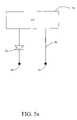
- FIG. 5is a perspective view of an interactor in accordance with the present invention.
- FIG. 5 ais a schematic representation of the internal circuitry of the interactor of FIG. 5 ;
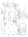
- FIG. 6is a schematic diagram of the circuitry of the detection field illustrated in FIGS. 3 and 4 ;
- FIG. 7is a flow diagram of a computer implemented process running on the microprocessor of FIG. 6 ;
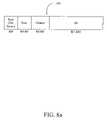
- FIG. 8 ais a data word produced by the process of FIG. 7 ;
- FIG. 8 bis a table illustrating the meanings associated with the state bit of the data word of FIG. 8 a;
- FIG. 9 aillustrates a one-dimensional detection field
- FIG. 9 billustrates both a three-dimensional and a four-dimensional detection field
- FIG. 9 cillustrates an alternative three-dimensional detection field
- FIG. 10illustrates an interactor used to control an audio system
- FIG. 11 aillustrates a first embodiment of the audio control system wherein the user is embodied into the system
- FIG. 11 billustrates a second embodiment of the audio control system wherein the user is not embodied into the system, i.e. is omniscient to the system;
- FIG. 11 cillustrates a layout of a two-dimensional detection field used for the audio control device
- FIG. 12is a block diagram for an audio control system of the present invention.
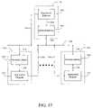
- FIG. 13is a block diagram representing the computer implemented processes running on the computers and server of FIG. 12 ;
- FIG. 14is a flow diagram illustrating the operation of the application program of FIG. 13 ;
- FIG. 15is a flow diagram illustrating the operation of the network library of FIG. 13 ;
- FIG. 16is a flow diagram illustrating the server software operation of FIG. 13 ;
- FIG. 17is an illustration of interactors on a detection field for marking events in temporal flows
- FIG. 18is a flow diagram of an event marker system in accordance with the present invention.
- FIG. 19is a flow diagram illustrating the “Control Media Based On Event” step of FIG. 18 ;
- FIG. 20is a flow diagram illustrating the “Process Binding Event” step of FIG. 18 ;
- FIG. 21is a flow diagram of the “Mark Temporal Flow” step of FIG. 18 ;
- FIG. 22is a flow diagram illustrating the “Process Other Event” step of FIG. 18 .
- an interactor system 10includes a detection space 12 , a controller computer 14 , and an optional system 16 .
- a number of interactors 18may be engaged with, moved around in, and removed from the detection space 12 .
- These interactors 18 in conjunction with the detection space 12help define a human/computer interface that is intuitive, flexible, rich in meaning, and is well adapted for use by multiple simultaneous users.
- detection spaceor the like will refer to any n-dimensional space in the physical world.
- the detection spacewill be alternatively referred to as a “detection field,” an “event field,” and the like. Therefore, such terms as “space,” “field,” “domain,” “volume,” should be considered as synonymous as used herein.
- fieldwill be used more frequently with respect to a two dimensional detection space
- spacewill be used more frequently with respect to a three dimensional detection space.
- any real-world detection spacewill have a three-dimensional aspect. However, if only two of those dimensions are used as input to the computer 14 , we will refer to the detection field as a “two dimensional.” Likewise, if only one-dimension is used as an input to computer 14 , we will refer herein to such a field as “one dimensional.” Furthermore, in certain embodiments of the present invention, the detection space may be time-variant, allowing the inclusion of four dimensional detection spaces. Various examples of detection spaces and fields will be discussed in greater detail subsequently.
- Computer 14is preferably a general purpose microcomputer made by any one of a variety of commercial vendors.
- computer 14can be a Macintosh computer system made by Apple Computer, Inc. or a PC/AT compatible DOS computer system made by Compaq, IBM, Packard-Bell, or others.
- Computer 14is coupled to the detection space 12 as indicated at 20 such that it may receive information concerning an interactor 18 placed within the detection space 12 .
- An interfaceis provided between the detection space 12 and the computer 14 which may be either internal to or external of the computer system 14 .
- the design and implementation of interfacesis well known to those skilled in the art, although a preferred implementation of an interface of the present invention will be discussed in greater detail subsequently.
- the system 16may serve as an input to computer 14 , an output from computer 14 , or both.
- the system 16can provide data on a line 22 which is used in conjunction with data on line 20 derived from the interaction of an interactor 18 with the detection space 12 .
- the system 16can be controlled by the interaction of the interactor 18 with the detection space 12 .
- the system 16can be of a standard commercial design (e.g. a videotape player), or can be a custom system designed for a particular use.
- the interactor system 24used to mark events in a temporal flow is illustrated somewhat schematically in FIG. 2 .
- the interactor system 24includes a detection field 26 , a computer 28 , and a video system 30 .
- a videotape or other video sourcecan be displayed on a screen 32 of the video system 30 and events can be “marked” by engaging interactors 34 with the detection field 26 .
- the images on video screen 32may be recorded such as within a recording/playback unit 35 of the video system 30 , or may be purely transitory images, such as those produced by a video camera 36 of the video system 30 . If recorded, the images can be “marked” contemporaneously with recording of the image, or after the fact. In the latter instance, the unit 35 would simply be used in its playback mode to playback an earlier recorded video tape for event marking.
- the detection field 26is, in this embodiment, a two-dimensional detection field in that it can detect positions of interactors 34 in both an “x” and a “y” direction. However, the detection field 26 of FIG. 2 does not detect vertical displacement from the detection field (i.e. in the z-direction) in this present embodiment.
- the detection field 26is provided with four, V-shaped channels 38 which permit the interactors 34 to be engaged with the detection field 26 at a convenient angle. A number (e.g. 12) of interactors 34 can be engaged with each of the channels 38 .
- the detection field 26is coupled to the computer 28 by an interface 40 . More particularly, a first cable 42 couples the detection field 26 to the interface 40 , and a second cable 44 couples the interface 40 to the computer 28 . The construction and operation of both the detection field 26 and interface 40 will be described in greater detail subsequently.
- the video system 30is coupled to computer 28 by a cable 46 .
- the computer 28includes an internal video interface card which engages with a suitable connector at one end of the cable 46 .
- Other embodimentshave other arrangements for connecting the video system to the computer.
- Video systems 30 and video system interface cards(not shown) are commercially available from such sources as Radius Corporation of California.
- the video camera 36can be coupled to the record/playback unit 35 by a cable 48 , or can be directly coupled into the computer 28 through the aforementioned video interface card (not shown).
- Video cameras such as video camera 36are available from a number of manufacturers including Sony Corporation of Japan.
- FIG. 3is a side elevational view of detection field 26 . Shown engaged with three of the four V-shaped channels 38 are interactors 34 . Again, while only one interactor is shown engaged with each of channels 38 , a number of interactors 34 (e.g. 12) can be simultaneously engaged with each of the channels.
- the body 50 of the detection field 26is preferably made from an insulating material such as wood or plastic.
- a plurality of permanent magnets 52are provided in a first wall 54 of each of the V-shaped channels 38 corresponding, one each, with positions where interactors can be engaged with the channels.
- the backs 56 of interactors 34are adapted to engage the walls 54 of the channels, i.e. preferably both the walls 54 of the channels and the backs 56 of the interactors are planar in configuration.
- Each of the interactors 34are also provided with a magnet 58 which is attracted to a magnet 52 when the back 56 of the interactor 34 is engaged with a wall 54 of the V-shaped channel 38 .
- each of the channels 38are provided with a number of contacts 64 and a grounding strip 66 .
- the contacts 64are electrically conducting and are located in walls 54 of the channels.
- the grounding strips 66are also electrically conducting and are connected near to the bottom of the walls 62 of the channels.
- an interactor 34makes electrical contact with one of the contacts 64 and with the grounding strip 66 when properly engaged with the V-shaped channel 38 .
- the magnets 52 and 58in addition to urging the interactor 34 into the channel 38 , also help assure that the interactor 34 is aligned properly in the x direction so that it makes good contact with the intended contact 64 . This desired result is accomplished because the magnets 52 and 58 will create a force that will attempt to align the interactor in the x direction.
- the contact 64 and the grounding strip 66can be made, for example, from copper or any other suitable conductive material.
- FIG. 5a perspective view of an interactor 34 shows the base 60 and back 56 .
- the body 68 of the interactor 34 of FIG. 5is a rectangular prism and is made from a non-conductive material such as wood or plastic.
- Base 60includes a foil member 70 which is adapted to engage the grounding strip 66 of the V-shaped channels 38 .
- Attached to the back 56is a contact 72 which is adapted to engage one of the contacts 64 of the V-shaped channels 38 .
- the foil 70 and contact 72are made from a suitable conductive material, such as copper.
- the interactors 34 and the detection field 26are sized for easy use and for the simultaneous use by several persons.
- the interactors 34can have dimensions of about 0.5 in. ⁇ 1.5 in. ⁇ 2.0 in.
- the detection fieldcan have dimensions of about 1 ft ⁇ 2 ft. ⁇ 3 in. in height. This permits the interactors 34 to be comfortably held in a user's hand, and allows multiple users to simultaneously interact with the detection field 26 .
- the internal circuitry of the interactor 34is shown.
- the circuitryincludes an identification (ID. chip 74 ), and a diode 76 .
- the ID chipis available from Dallas Semiconductor of Texas as part number DS2401, and provides a unique 48-bit identification (ID) when properly queried.
- the diode 76prevents false keying, as is well known to those skilled in the art of keyboard design.
- the ID chip 74is coupled to node 70 by the diode 76 , and is coupled to the contact 72 by a line 78 .
- the internal circuitry 80 of the detection field 26is illustrated. More particularly, the internal circuitry 80 includes the four grounding strips 66 and the contacts 64 described previously. The contacts 64 are coupled together in rows by lines 82 and are coupled to Vcc (e.g. 5 volts) by pull-up resistors 84 . Nodes of the circuitry 80 between the pull-up resistors 84 and the contacts 64 form a 12 bit bus which are input into a buffer register 86 . Likewise, grounding strips 66 are coupled into a four-bit bus and are input into the register 86 . A microprocessor 88 (such as an M68H141 made by Motorola of Austin, Tex.) communicates with the register 86 via a bus 90 .
- Vcce.g. 5 volts
- the register 86 and the microprocessor 88comprise the interface 40 , and the 12 bit bus and the 4 bit bus collectively forms the bus 42 .
- the output bus 44is under the control of microprocessor 88 .
- the interface 40will also include other well-known components, such as RAM for scratch-pad storage, ROM to store the control instructions for the microprocessor 88 , etc.
- a computer implemented process 92that runs on the microprocessor 88 to control the circuitry 80 will be described.
- the instructions for this process 92are stored in the aforementioned ROM of the interface 40 , as will be appreciated by those skilled in the art.
- the process 92begins at 94 and, in a first step 96 , the microprocessor 88 clears the bit maps.
- bit mapit is meant binary digits are mapped to particular locations on the board. These bit maps are preferably stored in the aforementioned RAM memory of the interface 40 .
- bit mapit is meant binary digits are mapped to particular locations on the board. These bit maps are preferably stored in the aforementioned RAM memory of the interface 40 .
- a step 98the rows and columns of the circuitry 80 are read and put into the current bit map.
- a debounce routineis performed.
- a “piece”is an interactor. By “marking” a location, a piece is engaged with the detection field 26 such that it makes electrical contact with the circuitry 80 .
- a step 104the ID of each of the pieces engaged with the detection field 26 is read, and is then compared to a list of the pieces (also stored in RAM memory of the interface 40 ).
- a reportis made that a new piece has been put down (i.e. engaged with the detection field 26 ) and an old piece has been picked up from the same position. This information is added to a queue stored in RAM.
- a step 108if the same piece is in the same position on the detection field, it is reported that the piece is still down.
- a step 110if a new piece is detected at a position, it is reported that a piece has been placed on to the detection field 26 .
- the bit mapis scanned in a step 112 for removed pieces and, if a removed piece is detected, the ID is reported.
- a step 116determines if there is a user request. If not, process control is returned to step 98 . If there is a user request, that user request is handled in a step 118 . In the current preferred embodiment, this involves processing the user request to handle the commands “get board state”, “get next event”, “get all events”, “erase all events”, and “get board type (version).” After the user request has been processed, process control is again returned to step 98 .
- a digital word 120 of the present inventionincludes a number of bits. More particularly, the current word includes 55 bits. Of the bits, a bit B 0 indicates the state, bits B 1 -B 2 indicate the row, and bits B 3 -B 6 indicates the column of the interactor. Finally, bits B 7 - 54 hold the 48 bit ID of the interactor. This data can be passed to the computer 28 via bus 44 .
- the word 120includes a state which is essentially exit/enter (up/down) for a particular interactor (i.e. when and how long has an interactor been positioned in the detection field). If the current state value is equal to 0, and the last state value is equal to 0, the meaning is that there is no piece (interactor) at that row and column position. If the current state is 1 and the last state is 0, that means that a piece has been put down at that row and column position. If the current state is 1 and the last state is 1, that means that the piece is still down since that last time that the detection field was scanned. Finally, if the current state is 0 and the last state is 1, that means that a piece has been picked up, i.e. an interactor has been removed from the detection field.
- FIGS. 9 a , 9 b , and 9 cillustrate three alternative embodiments for a detection field.
- a detection field 122allows an interactor 124 to be linearly placed in a multiplicity of positions along an x axis. This is an illustration of a one-dimensional detection field. It should be noted that, at the trivial extreme, if the detection field 122 is shortened sufficiently, it can be made just large enough to accept a single interactor 124 . This would comprise a zero-dimensional detection field which would simply detect the presence or absence of an interactor and its ID number, i.e. it can operate as a simple switch.
- a detection space 126is illustrated that can accept interactors 128 in three dimensions, i.e. along x, y, and z axes.
- the x, y, and z positions of an interactor 128can all be used to determine the context or meaning of the interactor.
- the base platform 130can have a different meaning from a first platform 132 , a second platform 134 , a third platform 136 , a fourth platform 138 , and a fifth platform 140 .
- Platform 136could, for example, be dedicated to changing the identity of one of the interactors 128 .
- Objects on platform 138could be “enclosing” interactors on platform 140 .
- the meaning and relationships of the various platformscan therefore be designed based upon desired functionalities specified by a user.
- a fourth dimensioncan be added to the detection space 126 of FIG. 9 b .
- the detection field 126can change with time.
- One way to accomplish thisis to allow the platforms to move over time such that their meanings change.
- platforms 134 , 136 , and 138can be allowed to move up and down, respectively, perhaps under the control of a motor (not shown).
- Thispermits an interactor 128 to have different meanings over a period of time.
- the interactor 128 on platform 134could represent a volume level for a loudspeaker which will diminish over time as the platform moves downwardly in a z direction. Therefore, it should be clear from the foregoing that the detection spaces or fields can be n-dimensional where n is 0, 1, 2, 3, etc.
- a detection space 148 in the form of a spherical globeis provided where a number of interactors have been adhered (such as by magnets) to its surface. With such spherical detection spaces or fields, it may be more convenient to determine the position of the interactors using a spherical coordinate system. It should also be noted that other forms of detection fields can be provided including detection fields of irregular shapes.
- an interactor 152is shown which will be used for a particular implementation of the present invention.
- the interactor 152includes a body 154 that operates functionally in a fashion very similar to that of the interactor 34 illustrated in FIGS. 5 and 5 a .
- the interactor 152can be used with a detection field similar to or identical with detection field 26 as illustrated in FIGS. 3 , 4 , and 6 .
- the detection field 26 used with the interactor 152can also use the same interface 40 to interconnect the field with a computer system 28 .
- interactor 152The difference between interactor 152 and the previously described interactor 34 is therefore design related and not computational in nature in that they support different metaphors.
- a doll's head 156 or other talismanis provided with a peg 158 which can engage a hole 160 in the body 154 .
- a small piece of white board 162is removably attached to the body 154 by a pair of hook-and-pile (e.g. Velcro®) members 164 a and 164 b .
- the hook-and-pile member 164 ais attached to a surface of body 154 while member 164 b is attached to the back of the white board 162 .
- the white board 162can be removably attached to the body 154 of the interactor 152 .
- a name, label, or other indiciacan be provided on the white board 162 with a marker 166 as illustrated by the name “Fred.” Therefore, the interactor 152 can be used to represent a person named Fred both by means of the head configuration 156 and the name on the white board 162 . It is a useful feature of the present invention in that interactors can be given distinct visual, aural or other sensory identities which aid in the metaphor of the human-computer interface.
- a detection field 166has a number of interactors 168 that can be positioned at various locations.
- one of the interactors 168 arepresents the user herself.
- the other interactors 168 in this examplerepresent other people.
- the piecescan be moved around such that their relative x, y positions change with respect to each other. It is therefore possible with the interactors of the present invention to create a “virtual room” wherein the utterances made by various persons represented by the interactors appear to be spatially located as indicated by the interactors. Therefore, the interactors and detection fields of the present invention can be used as a controller for forming groups in a “virtual room” and for varying the relative location of the various members of the group.
- FIG. 11 ba slightly altered detection field 166 ′ is used for substantially the same purpose as previously described.
- an interactor representing the user herselfis within the detection field 166
- the userdoes not have an interactor representing herself on the detection field 166 ′.
- the useris said to be “embodied” in that she is on the detection field and can move on the detection field relative to other interactors.
- the position of the useris fixed at some point, either off or on the detection field 166 ′.
- the usermight be positioned at a point 170 just off of the detection field 166 ′.
- the other people represented by interactors 168can be adjusted relative to the user to obtain much of the effect obtainable by the embodiment illustrated in FIG. 11 a.
- FIG. 11 ca potential “layout” of a detection field 166 is illustrated. If an interactor is placed near the back of the field, the volume associated with the person represented by that interactor is at its softest. Placing the interactor near the front of the field will make the associated person the loudest. Special positions on the left and right edges and down the center of the detection field can perform special functions, such as “pan”, “get info”, or “assign.”
- an interactor system 172 in accordance with the present inventionincludes an audio server 174 and a number of workstations 176 .
- the interactor system 172can perform the functionality described with respects to FIGS. 11 a and 11 b.
- the audio server 174includes a data server 178 , a MIDI timepiece 180 , a number of MIDI devices 182 , and an audio concentrator 184 .
- the data server 178receives data from a network bus 186 and is connected to the MIDI timepiece 180 by a bus 188 .
- the MIDI timepiece 180is connected to a rack of MIDI devices 182 by a bus 190 , and the output of the MIDI devices 182 are coupled to the concentrator 184 by a bus 192 .
- the concentrator 184has, as inputs, a number of audio lines 194 .
- Each workstation 176includes a computer 196 , interfaces 198 , and detection fields 200 as described previously.
- the detection fields 200can have one or more interactors 202 placed upon their surfaces as previously illustrated and described with reference to FIGS. 11 a and 11 b .
- the workstationfurther includes a pair of stereo loudspeakers 204 and a pair of stereo microphones 206 .
- the loudspeakers 204are coupled directly into a control box 208 which include loudspeaker amplifiers.
- the microphonesare coupled to a pre-amplifier 210 which, in turn, are coupled to the control box 208 .
- the control box 208also includes microphone amplifiers.
- the audio lines 194carry the microphone signals to the concentrator 184 , and the loudspeaker signals from the concentrator 184 to the various speakers 204 .
- the software operating the interactor system 172is conceptually illustrated in block diagram form in FIG. 13 .
- the databus 186carries the data necessary to interconnect the various components of the system 172 and can, for example, be implemented on an Apple LocalTalk or Ethernet network protocol. It should be understood, however, that other network protocols such as Novell Netware or custom network software can also be used to provide the networking functions of the network bus 186 .
- each of the workstations 176operate an application program and a network library, and a data server 178 operates data server software and the network library.
- the application program 212runs on the computer 196 of each of the workstations 176 that are part of the interactor system 172 .
- Network libraries 214likewise each run on a computer system 196 .
- the network librarycommunicates with the network bus 186 via a conceptual link 216 and with the application program via a conceptual link 218 .
- the application program 212communicates with the network bus 186 via a conceptual link 220 .
- the links 216 , 218 , and 220are considered conceptual in that they are not physical links to the bus but, rather, logical links through operating system software, network software, internal buses, network cards, etc.
- the software running on the data server 178includes the network library 222 and the data server software 224 .
- the network libraryhas a conceptual link 226 to the network bus and a conceptual link 228 to the data server software 224 .
- the data server softwarehas a conceptual link 230 to the network bus 186 .
- the conceptual links 220 and 230 from the network bus 186 to the application programs 212 and to data server software 224 , respectivelyare AppleEvents created by an Apple networking system.
- the conceptual links 216 and 226 between the network library and the network bus 186are preferably standard AppleTalk or Ethernet data packages.
- FIG. 14illustrates the application program 212 running on the workstations 176 .
- the process 212begins at 232 and, in a step 234 , the process is initialized with the board type, and the current board space.
- a step 236the state of all persons on the system is communicated based upon the board state and board type.
- the processenters an event queue 238 to await the next event. If the next event is a “pick-up” event, a step 240 determines whether the interactor is in a control space.
- a control spaceis a dedicated portion of a detection field used to control the process. If it is an assignment control space (where meanings are assigned to interactors) control is returned to the step 238 . If the control space is a people control space, the audio is cut off in a step 242 and process control is again returned to step 238 .
- step 240determines that the interactor is not in a control space, it is determined in step 246 if the board (i.e. the detection field) is self-embodied. If yes, it is determined in a step 248 if the interactor representing the user (“self”) has been removed from the board. If not, the system provides an audio feedback and a new state to the server in a step 250 . If the interactor representing the user has been removed from a self-embodied board, a step 252 provides audio feedback and turns off the sound to all users.
- the boardi.e. the detection field
- a step 254determines whether it was put down into a control space. If yes, people information is provided in a step 256 . If it was put into an assignment space, a step 258 inputs the assignment to the interactor. After either step 256 or 258 are completed, process control is returned to step 238 .
- a step 260it is determined whether there is a self-embodied board. If yes, a step 268 determines whether an interactor representing the user has been placed on the detection field. If not, or if step 260 determines that is not a self-embodied board, a step 264 provides audio feedback and resets the data concerning the person represented by the interactor.
- step 268determines an interactor representing the user has been placed on the detection field, audio feedback is provided, and a reset of all of the people represented by the interactors on the board is initiated. After steps 264 or 266 is completed, process control is returned to step 238 .
- the process 214begins at 268 and, in a step 270 , it is determined whether a function call has been received. If not, the process 214 goes into an idle loop awaiting a function call. If a function call “receive event” has been received, a step 272 provides a requesting program with the information regarding the event. If a functional call corresponding to “send event” is received, an AppleEvent is created from the function call to communicate with other programs in a step 274 . Process control is returned to the function call event loop 270 after the completion of either steps 272 or 274 .
- a process 224begins at 276 and, in a step 278 , it is determined whether an AppleEvent has been received. Again, this process 224 is Macintosh® specific, and like or equivalent processes can be used in other types of computer systems. If an AppleEvent has not been received, the AppleEvent loop 278 repeats until that AppleEvent is received. If the AppleEvent is a “value change” AppleEvent, a step 280 determines whether there is a privacy violation. If yes, a step 282 notifies an error handler to handle the privacy violation. Process control is then returned to step 278 .
- step 280If there is not privacy violation detected by step 280 , there is an update of dynamic information database in a step 284 .
- step 286MIDI data is calculated and sent.
- a step 288users with a vested interest in the function are notified, and process control is returned to step 278 .
- a step 290determines whether there is a privacy violation. If yes, a step 292 notifies the network library with the error function and process control is returned to step 278 . If there is not a privacy violation as determined by step 290 , information is retrieved from the database in a step 294 . Finally, in a step 296 , the network library is called to reply and process control is returned to step 278 .
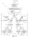
- an interactor systemsuch as interactor system 24 is controlled to “mark” or “log” events in a videotape.
- a detection field 298includes three zones 300 a , 300 b , 300 c and a number of interactors 302 .
- Each of the interactorshas a semantic meaning due to its identity, due to their position in the various zones 300 a , 300 b , and 300 c of the detection field 298 , and due to their amount or “type” of time they have been present in the detection field (up/down or, as sometimes referred to herein, exit/enter).
- the various objects 302can be used mark and control the temporal flow of a recorded medium as described previously with regards to FIG. 2 .
- temporal flowwill refer to the flow of events, either in real time or in some other time related context. Therefore, either events can be marked in a temporal flow, or events that have been previously recorded or that are being concurrently recorded can be marked in the temporal flow.
- the “marking”may only be literally temporal (such as in real time), temporal with regard to a specific origin (such as seconds since the start of the tape), or temporal only in the sense that the measure could be translated into a temporal stream (such as feet of tape or frame number). While the present example relates to a recorded video medium, the marking and control of the temporal flow of another medium, such as an audio medium, may also be carried out.
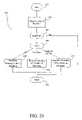
- a computer implemented process 304 operating on a computer 28 of FIG. 2 for marking and controlling a temporal flowbegins at 306 and, in a step 308 , it is determined whether a non-board event has been received. If so, this “other” type of event is processed in a step 310 and process control is returned to step 308 .
- a step 312it is determined whether a board event has been received. If not, process control is returned to step 308 . If a board event has been received, the board is polled in a step 314 and it is determined in a step 316 whether a null board event has been received.
- a null board eventmay be that no interactors have been perceived in the detection field, or that no changes have been detected in the state of the interactors in the detection field. If so, process control returns to 308 . However, if a board event has been received (i.e. it is not a null board event), the board event is parsed in a step 318 . Next, in a step 320 , it is determined the event type based upon any combination (e.g., any one, any two, or all three) of the interactor's ID, location, and whether it is up or down (i.e. the time period of the interactor in the detection field). Next, in a step 332 , the parsed event is processed by type.
- a step 324controls the media based upon the event. If it is a binding event, a step 326 processes the binding event. If it is a marking event, a step 324 marks the temporal flow. In this instance, the temporal flow is marked by receiving frame information from the video player and storing that frame information along with the event type in a database on the computer 28 . If the event type is unrecognized, or after steps 324 , 326 , or 328 have been processed, process control returns to step 308 .
- Step 324 of FIG. 18is illustrated in greater detail in FIG. 19 .
- process 324begins at 320 and, in a step 332 , the meaning of the interactor in the detection field is determined from its ID, its location, and whether it is up or down. The meaning may be determined based upon any combination of the presence of the interactor (up/down), the ID of the interactor, and the location of the interactor.
- this meaningis converted into control commands (e.g. stop, fast-forward, speed etc.) for the media system.
- the process 324is completed at 336 .
- Step 326 of FIG. 18is illustrated in greater detail in FIG. 20 .
- Process 326begins at 338 and, in a step 340 , the current meaning of the interactor is displayed. The system then determines whether the user wants to redefine the current meaning of the interactor in a step 342 . If not, the process 326 is completed as indicated at 352 . If the user does wish to redefine the meaning of a particular interactor, it is determined in a step 344 what type of redefinition is desired. If the meaning of the location is “re-bind the ID”, then a step 346 redefines the binding of the ID to the meaning. If the meaning of the object is “re-define the location”, the system redefines the binding of the location to the meaning in a step 348 .
- a step 350is redefines the binding of the proximity to the meaning.
- proximityis a measure of distance between the interactor and the detection field, or the position of an interactor in a detection space.
- the step 238 of FIG. 18is illustrated in greater detail in FIG. 21 .
- the process 328begins at 352 and, in a step 354 , the current temporal value of the media is retrieved.
- a markis stored with a temporal value and meaning based upon the ID, location, and how the interactor has been placed “up or down” in the detection field.
- the process 328is then completed at 358 .
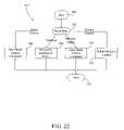
- the step 310 of FIG. 18is illustrated in greater detail in FIG. 22 .
- the process 310begins at 360 and, in a step 362 , an event type is determined. If the event type is board control, a step 364 issues board control commands. If the event type is “database,” a step 366 manipulates the database of marks. If the event type is “navigate media,” a media control command is issued by step 368 . If the event type is “device control,” a device to control is selected in a step 370 . After the completion of steps 364 , 366 , 368 , or 370 , the process 310 is completed as indicated at 372 .
Landscapes
- Engineering & Computer Science (AREA)
- General Engineering & Computer Science (AREA)
- Theoretical Computer Science (AREA)
- Human Computer Interaction (AREA)
- Physics & Mathematics (AREA)
- General Physics & Mathematics (AREA)
- Multimedia (AREA)
- Signal Processing (AREA)
- User Interface Of Digital Computer (AREA)
- Machine Translation (AREA)
- Processing Or Creating Images (AREA)
Abstract
Description
Claims (20)
Priority Applications (2)
| Application Number | Priority Date | Filing Date | Title |
|---|---|---|---|
| US11/061,789US7545359B1 (en) | 1995-08-03 | 2005-02-18 | Computerized interactor systems and methods for providing same |
| US12/390,623US8154511B2 (en) | 1995-08-03 | 2009-02-23 | Computerized interactor systems and methods for providing same |
Applications Claiming Priority (5)
| Application Number | Priority Date | Filing Date | Title |
|---|---|---|---|
| US187595P | 1995-08-03 | 1995-08-03 | |
| US69283096A | 1996-07-29 | 1996-07-29 | |
| US08/801,085US6262711B1 (en) | 1995-08-03 | 1997-02-14 | Computerized interactor systems and method for providing same |
| US09/823,628US6940486B2 (en) | 1995-08-03 | 2001-03-30 | Computerized interactor systems and methods for providing same |
| US11/061,789US7545359B1 (en) | 1995-08-03 | 2005-02-18 | Computerized interactor systems and methods for providing same |
Related Parent Applications (1)
| Application Number | Title | Priority Date | Filing Date |
|---|---|---|---|
| US09/823,628ContinuationUS6940486B2 (en) | 1995-08-03 | 2001-03-30 | Computerized interactor systems and methods for providing same |
Related Child Applications (1)
| Application Number | Title | Priority Date | Filing Date |
|---|---|---|---|
| US12/390,623ContinuationUS8154511B2 (en) | 1995-08-03 | 2009-02-23 | Computerized interactor systems and methods for providing same |
Publications (1)
| Publication Number | Publication Date |
|---|---|
| US7545359B1true US7545359B1 (en) | 2009-06-09 |
Family
ID=26669597
Family Applications (3)
| Application Number | Title | Priority Date | Filing Date |
|---|---|---|---|
| US08/801,085Expired - LifetimeUS6262711B1 (en) | 1995-08-03 | 1997-02-14 | Computerized interactor systems and method for providing same |
| US11/061,789Expired - Fee RelatedUS7545359B1 (en) | 1995-08-03 | 2005-02-18 | Computerized interactor systems and methods for providing same |
| US12/390,623Expired - Fee RelatedUS8154511B2 (en) | 1995-08-03 | 2009-02-23 | Computerized interactor systems and methods for providing same |
Family Applications Before (1)
| Application Number | Title | Priority Date | Filing Date |
|---|---|---|---|
| US08/801,085Expired - LifetimeUS6262711B1 (en) | 1995-08-03 | 1997-02-14 | Computerized interactor systems and method for providing same |
Family Applications After (1)
| Application Number | Title | Priority Date | Filing Date |
|---|---|---|---|
| US12/390,623Expired - Fee RelatedUS8154511B2 (en) | 1995-08-03 | 2009-02-23 | Computerized interactor systems and methods for providing same |
Country Status (7)
| Country | Link |
|---|---|
| US (3) | US6262711B1 (en) |
| EP (1) | EP0842490B1 (en) |
| JP (1) | JP2001517331A (en) |
| KR (1) | KR100404918B1 (en) |
| AU (1) | AU6646096A (en) |
| DE (1) | DE69637146T2 (en) |
| WO (1) | WO1997006479A2 (en) |
Cited By (4)
| Publication number | Priority date | Publication date | Assignee | Title |
|---|---|---|---|---|
| US20090174654A1 (en)* | 1995-08-03 | 2009-07-09 | Cohen Jonathan R | Computerized interactor systems and methods for providing same |
| US20100005480A1 (en)* | 2008-07-07 | 2010-01-07 | International Business Machines Corporation | Method for virtual world event notification |
| US7953112B2 (en) | 1997-10-09 | 2011-05-31 | Interval Licensing Llc | Variable bandwidth communication systems and methods |
| US8509137B2 (en) | 1997-10-09 | 2013-08-13 | Interval Licensing Llc | Method and apparatus for sending presence messages |
Families Citing this family (26)
| Publication number | Priority date | Publication date | Assignee | Title |
|---|---|---|---|---|
| US6940486B2 (en)* | 1995-08-03 | 2005-09-06 | Vulcan Patents Llc | Computerized interactor systems and methods for providing same |
| WO2001040921A1 (en)* | 1999-12-01 | 2001-06-07 | Lego A/S | Remote data access through manipulation of physical objects |
| US6720956B1 (en)* | 2000-06-30 | 2004-04-13 | Intel Corporation | Apparatus and method for obtaining geographical information using a touch-sensitive globe device |
| US20020075231A1 (en)* | 2000-12-18 | 2002-06-20 | Philips Eelectronics North America | Adaptable remote control with exchangeable controls |
| US20020107679A1 (en)* | 2001-02-05 | 2002-08-08 | Koninklijke Philips Electronics N. V. | Virtual model generation via physical components |
| US20040168206A1 (en)* | 2001-05-14 | 2004-08-26 | Stienstra Marcelle Andrea | Device for interacting with real-time streams of content |
| US8556712B2 (en) | 2001-05-17 | 2013-10-15 | Koninklijke Philips N.V. | System for presenting interactive content |
| US7916124B1 (en) | 2001-06-20 | 2011-03-29 | Leapfrog Enterprises, Inc. | Interactive apparatus using print media |
| GB0204686D0 (en) | 2002-02-28 | 2002-04-17 | Koninkl Philips Electronics Nv | Interactive system using tags |
| US20040229195A1 (en)* | 2003-03-18 | 2004-11-18 | Leapfrog Enterprises, Inc. | Scanning apparatus |
| JP2004348647A (en)* | 2003-05-26 | 2004-12-09 | Hitachi Ltd | Human communication system |
| US20050142263A1 (en)* | 2003-12-30 | 2005-06-30 | Lauren Keilbach | Fish food flakes |
| US20060066591A1 (en)* | 2004-03-17 | 2006-03-30 | James Marggraff | Method and system for implementing a user interface for a device through recognized text and bounded areas |
| US20060078866A1 (en)* | 2004-03-17 | 2006-04-13 | James Marggraff | System and method for identifying termination of data entry |
| US20060033725A1 (en)* | 2004-06-03 | 2006-02-16 | Leapfrog Enterprises, Inc. | User created interactive interface |
| US7831933B2 (en) | 2004-03-17 | 2010-11-09 | Leapfrog Enterprises, Inc. | Method and system for implementing a user interface for a device employing written graphical elements |
| US7453447B2 (en)* | 2004-03-17 | 2008-11-18 | Leapfrog Enterprises, Inc. | Interactive apparatus with recording and playback capability usable with encoded writing medium |
| US7853193B2 (en) | 2004-03-17 | 2010-12-14 | Leapfrog Enterprises, Inc. | Method and device for audibly instructing a user to interact with a function |
| JP4546151B2 (en)* | 2004-05-26 | 2010-09-15 | 株式会社日立製作所 | Voice communication system |
| JP2006025281A (en)* | 2004-07-09 | 2006-01-26 | Hitachi Ltd | Information source selection system and method |
| WO2006129250A1 (en)* | 2005-06-01 | 2006-12-07 | Koninklijke Philips Electronics N.V. | Atmosphere device with user interface for light and fragrance control |
| US7922099B1 (en) | 2005-07-29 | 2011-04-12 | Leapfrog Enterprises, Inc. | System and method for associating content with an image bearing surface |
| US7720552B1 (en) | 2006-06-05 | 2010-05-18 | Rockwell Automation Technologies, Inc. | Virtual knob lever arm as analog control element |
| US8261967B1 (en) | 2006-07-19 | 2012-09-11 | Leapfrog Enterprises, Inc. | Techniques for interactively coupling electronic content with printed media |
| KR100802503B1 (en)* | 2007-04-06 | 2008-02-12 | 주식회사 나루기술 | Dimensional Expandable RFID ID Tag |
| FR3000817B1 (en)* | 2013-01-04 | 2016-04-01 | Epawn | CONTROLLING A MOBILE DEVICE MOVING HOME STATION |
Citations (111)
| Publication number | Priority date | Publication date | Assignee | Title |
|---|---|---|---|---|
| US3673327A (en) | 1970-11-02 | 1972-06-27 | Atomic Energy Commission | Touch actuable data input panel assembly |
| US3891829A (en) | 1973-08-29 | 1975-06-24 | Monarch Marking Systems Inc | Coded records, method of making same and method and an apparatus for reading coded records |
| US3894756A (en) | 1971-10-18 | 1975-07-15 | Optronics Int | Identification card having a reference beam coded hologram |
| US4114033A (en) | 1976-02-18 | 1978-09-12 | Nippondenso Co., Ltd. | Bar code information card |
| US4172969A (en) | 1975-12-03 | 1979-10-30 | Boris Haskell | Real time absentee telephone and radiant wave signaling system |
| US4237344A (en) | 1979-04-20 | 1980-12-02 | Hospital Communication Systems, Inc. | Rapid response health care communications system |
| SU844011A1 (en) | 1979-07-10 | 1981-07-07 | Винницкий Завод Радиотехнической Аппаратуры | Game |
| DE3008190A1 (en) | 1980-03-04 | 1981-09-10 | Institut für Rundfunktechnik GmbH, 8000 München | Cutting and assembling video and/or audio recording carrier - using off=line marker programming kit with keyboard and display |
| US4302011A (en) | 1976-08-24 | 1981-11-24 | Peptek, Incorporated | Video game apparatus and method |
| US4341385A (en) | 1980-01-24 | 1982-07-27 | Doyle Holly Thomis | Electronic board game apparatus |
| US4536887A (en) | 1982-10-18 | 1985-08-20 | Nippon Telegraph & Telephone Public Corporation | Microphone-array apparatus and method for extracting desired signal |
| GB2103943B (en) | 1981-07-21 | 1985-09-04 | Scisys W Limited | Electronic game board |
| US4597495A (en) | 1985-04-25 | 1986-07-01 | Knosby Austin T | Livestock identification system |
| FR2607400A1 (en) | 1986-11-27 | 1988-06-03 | Chacun Patrick | Improvement to parlour games |
| US4780883A (en) | 1986-06-26 | 1988-10-25 | Racal Data Communications Inc. | Data modem with adaptive synchronized speed change |
| US4843568A (en) | 1986-04-11 | 1989-06-27 | Krueger Myron W | Real time perception of and response to the actions of an unencumbered participant/user |
| US4866765A (en) | 1987-09-30 | 1989-09-12 | Yang Tai Cheng | Toy type children telephone set |
| US4873398A (en) | 1988-06-30 | 1989-10-10 | Hewlett-Packard Company | Flat panel display with integrated digitizing tablet |
| DE3813779A1 (en) | 1988-04-23 | 1989-11-02 | Hegener & Glaser Ag | Figure identification for a game |
| US4882726A (en) | 1987-11-23 | 1989-11-21 | Motorola Canada Limited | Full duplex modem system for differing data bit rates |
| US4887204A (en) | 1987-02-13 | 1989-12-12 | International Business Machines Corporation | System and method for accessing remote files in a distributed networking environment |
| US4893305A (en) | 1988-03-31 | 1990-01-09 | Racal Data Communications Inc. | Inband dynamic port allocation |
| GB2226468A (en) | 1988-12-22 | 1990-06-27 | Rank Cintel Ltd | Image processing system |
| US4940963A (en) | 1989-03-10 | 1990-07-10 | Motorola Inc. | Paging system with improved acknowledge-back capabilities |
| US4975694A (en) | 1989-03-14 | 1990-12-04 | Motorola, Inc. | Paging receiver with variable color indicators |
| US4998010A (en) | 1988-04-08 | 1991-03-05 | United Parcel Service Of America, Inc. | Polygonal information encoding article, process and system |
| US5013047A (en) | 1986-03-12 | 1991-05-07 | Dr. Schwab Gesellschaft fur Technologieberatung mbH | Apparatus for determining the identity and position of game objects |
| US5047614A (en) | 1989-01-23 | 1991-09-10 | Bianco James S | Method and apparatus for computer-aided shopping |
| US5082286A (en) | 1989-09-07 | 1992-01-21 | Saitek Limited | Sensory games |
| US5086394A (en) | 1989-05-12 | 1992-02-04 | Shmuel Shapira | Introduction system for locating compatible persons |
| US5088928A (en) | 1988-11-15 | 1992-02-18 | Chan James K | Educational/board game apparatus |
| US5188368A (en) | 1989-10-25 | 1993-02-23 | Saitek Limited | Electronic game apparatus |
| US5202828A (en) | 1991-05-15 | 1993-04-13 | Apple Computer, Inc. | User interface system having programmable user interface elements |
| US5231649A (en) | 1991-08-08 | 1993-07-27 | Ascend Communications, Inc. | Method and apparatus for dynamic bandwidth allocation in a digital communication session |
| US5257307A (en) | 1990-02-07 | 1993-10-26 | Sharp Kabushiki Kaisha | Radio pager system which transmits secret coded messages from a caller to a pager terminal apparatus |
| US5267323A (en) | 1989-12-29 | 1993-11-30 | Pioneer Electronic Corporation | Voice-operated remote control system |
| EP0576187A1 (en) | 1992-06-16 | 1993-12-29 | Elbit Ltd. | Tracker employing a rotating electromagnetic field |
| US5298731A (en) | 1992-12-23 | 1994-03-29 | International Business Machines Corporation | Method for printing and reading for orthogonal bar code patterns |
| US5303388A (en) | 1990-05-09 | 1994-04-12 | Apple Computer, Inc. | Method to display and rotate a three-dimensional icon with multiple faces |
| GB2237514B (en) | 1989-10-07 | 1994-05-04 | David Taylor | Computer board game |
| US5330380A (en) | 1993-03-15 | 1994-07-19 | Link Group International | Audible message/information delivery system |
| EP0606790A2 (en) | 1992-12-08 | 1994-07-20 | Steven Lebensfeld | Subject specific,word/phrase selectable, message delivering doll or action figure |
| US5335011A (en) | 1993-01-12 | 1994-08-02 | Bell Communications Research, Inc. | Sound localization system for teleconferencing using self-steering microphone arrays |
| US5337358A (en) | 1992-11-20 | 1994-08-09 | Pitney Bowes Inc. | Apparatus for recording a transaction including authenticating an identification card |
| US5359422A (en)* | 1988-06-29 | 1994-10-25 | Canon Kabushiki Kaisha | Display device having a plurality of display modes |
| US5360446A (en) | 1992-12-18 | 1994-11-01 | Zimmer, Inc. | Interactive prosthesis design system for implantable prosthesis |
| US5396265A (en) | 1990-09-17 | 1995-03-07 | Massachusetts Institute Of Technology | Three-dimensional tactile computer input device |
| US5401947A (en) | 1994-03-15 | 1995-03-28 | Poland; Terrell A. | Information display and product identification system |
| JPH0793567B2 (en) | 1987-05-08 | 1995-10-09 | 日本電信電話株式会社 | Power supply circuit for constant current source control of current switching type logic circuit |
| US5459458A (en) | 1993-07-06 | 1995-10-17 | Motorola, Inc. | Virtual pager for general purpose data terminal |
| JPH07108786B2 (en) | 1990-02-19 | 1995-11-22 | カール−ツァイス−スティフツング | Lead-zinc-borosilicate glass |
| US5479408A (en) | 1994-02-22 | 1995-12-26 | Will; Craig A. | Wireless personal paging, communications, and locating system |
| US5481610A (en) | 1994-02-28 | 1996-01-02 | Ericsson Inc. | Digital radio transceiver with encrypted key storage |
| US5483261A (en) | 1992-02-14 | 1996-01-09 | Itu Research, Inc. | Graphical input controller and method with rear screen image detection |
| US5487181A (en) | 1992-10-28 | 1996-01-23 | Ericsson Ge Mobile Communications Inc. | Low power architecture for portable and mobile two-way radios |
| US5511148A (en) | 1993-04-30 | 1996-04-23 | Xerox Corporation | Interactive copying system |
| US5525798A (en) | 1994-12-01 | 1996-06-11 | Pitney Bowes Inc. | Bar code scanner for reading a lower layer luminescent invisible ink that is printed below a upper layer luminescent invisible ink |
| US5537336A (en) | 1994-03-30 | 1996-07-16 | On-Site Analysis, Inc. | On-site oil analyzer |
| US5545883A (en) | 1993-07-13 | 1996-08-13 | Tamura Electric Works, Ltd. | Magnetic card and card reader apparatus utilizing a pseudo bar code and an address information code |
| US5550561A (en) | 1995-01-11 | 1996-08-27 | Ziarno; Witold A. | Display cursor controlling device for reading card information from an information bearing credit or debit card |
| US5561446A (en) | 1994-01-28 | 1996-10-01 | Montlick; Terry F. | Method and apparatus for wireless remote information retrieval and pen-based data entry |
| US5572643A (en) | 1995-10-19 | 1996-11-05 | Judson; David H. | Web browser with dynamic display of information objects during linking |
| US5586216A (en) | 1992-09-25 | 1996-12-17 | Apple Computer, Inc. | Recording method and apparatus and audio data user interface |
| US5590396A (en) | 1994-04-20 | 1996-12-31 | Ericsson Inc. | Method and apparatus for a deep-sleep mode in a digital cellular communication system |
| WO1997001137A1 (en) | 1995-06-20 | 1997-01-09 | Solar Communications, Inc. | System for using article of commerce to access remote computer |
| US5600115A (en) | 1996-01-16 | 1997-02-04 | Balzano; Alfiero | Flexible cable with security system for code markings |
| US5604516A (en) | 1994-06-30 | 1997-02-18 | Symbol Technologies, Inc. | Graphical user interface control for providing both automatic and manual data input |
| US5640193A (en) | 1994-08-15 | 1997-06-17 | Lucent Technologies Inc. | Multimedia service access by reading marks on an object |
| US5644627A (en) | 1995-03-29 | 1997-07-01 | Motorola, Inc. | Method and apparatus for processing a voice message intended for a selective call transceiver |
| US5651049A (en) | 1994-08-30 | 1997-07-22 | Harris Corporation | RF connected message recording device and method for a telephone system |
| JPH09204389A (en) | 1996-01-26 | 1997-08-05 | Sony Corp | Information processor, its method and printed object |
| US5664015A (en) | 1995-06-15 | 1997-09-02 | Jing Mei Industrial Holdings, Inc. | Shower speaker telephone |
| WO1997032262A1 (en) | 1996-03-01 | 1997-09-04 | Cobblestone Software, Inc. | Variable formatting of digital data into a pattern |
| US5666215A (en) | 1994-02-25 | 1997-09-09 | Eastman Kodak Company | System and method for remotely selecting photographic images |
| US5670987A (en) | 1993-09-21 | 1997-09-23 | Kabushiki Kaisha Toshiba | Virtual manipulating apparatus and method |
| US5674003A (en) | 1995-04-28 | 1997-10-07 | Andersen; David B. | Mechanisms for accessing unique features of telephony networks from a protocol-Independent data transport interface |
| US5684885A (en) | 1995-09-27 | 1997-11-04 | Xerox Corporation | Binary glyph codes based on color relationships |
| US5689641A (en) | 1993-10-01 | 1997-11-18 | Vicor, Inc. | Multimedia collaboration system arrangement for routing compressed AV signal through a participant site without decompressing the AV signal |
| US5693693A (en) | 1994-12-01 | 1997-12-02 | Pitney Bowes, Inc. | Bar code printing and scanning using wax based invisible fluorescent inks |
| WO1998003923A1 (en) | 1996-07-21 | 1998-01-29 | Ernestine, Llc | World wide web bar code access system |
| US5729251A (en) | 1995-02-09 | 1998-03-17 | Fuji Xerox Co., Ltd. | Information input/output system |
| US5733131A (en) | 1994-07-29 | 1998-03-31 | Seiko Communications Holding N.V. | Education and entertainment device with dynamic configuration and operation |
| US5734724A (en) | 1995-03-01 | 1998-03-31 | Nippon Telegraph And Telephone Corporation | Audio communication control unit |
| US5739814A (en)* | 1992-09-28 | 1998-04-14 | Sega Enterprises | Information storage system and book device for providing information in response to the user specification |
| US5765151A (en) | 1995-08-17 | 1998-06-09 | Sun Microsystems, Inc. | System and method for file system fix-on-panic for a computer operating system |
| JPH10171758A (en) | 1996-12-06 | 1998-06-26 | Neolex:Kk | Www file reading system using bar code |
| US5790138A (en) | 1996-01-16 | 1998-08-04 | Monolithic System Technology, Inc. | Method and structure for improving display data bandwidth in a unified memory architecture system |
| US5802488A (en) | 1995-03-01 | 1998-09-01 | Seiko Epson Corporation | Interactive speech recognition with varying responses for time of day and environmental conditions |
| US5804803A (en) | 1996-04-02 | 1998-09-08 | International Business Machines Corporation | Mechanism for retrieving information using data encoded on an object |
| US5815142A (en) | 1994-07-25 | 1998-09-29 | International Business Machines Corporation | Apparatus and method for marking text on a display screen in a personal communications device |
| US5826253A (en) | 1995-07-26 | 1998-10-20 | Borland International, Inc. | Database system with methodology for notifying clients of any additions, deletions, or modifications occurring at the database server which affect validity of a range of data records cached in local memory buffers of clients |
| US5832119A (en) | 1993-11-18 | 1998-11-03 | Digimarc Corporation | Methods for controlling systems using control signals embedded in empirical data |
| US5839054A (en) | 1996-01-02 | 1998-11-17 | Brother International Corporation | Automatic registration paging system |
| US5841978A (en) | 1993-11-18 | 1998-11-24 | Digimarc Corporation | Network linking method using steganographically embedded data objects |
| US5848413A (en) | 1995-01-13 | 1998-12-08 | Ricoh Company, Ltd. | Method and apparatus for accessing and publishing electronic documents |
| US5862321A (en) | 1994-06-27 | 1999-01-19 | Xerox Corporation | System and method for accessing and distributing electronic documents |
| US5862429A (en) | 1996-07-10 | 1999-01-19 | Kabushiki Kaishi Toshiba | Image forming apparatus method for manufacturing the same and method for maintaining the same |
| US5869819A (en) | 1994-08-17 | 1999-02-09 | Metrologic Instuments Inc. | Internet-based system and method for tracking objects bearing URL-encoded bar code symbols |
| US5886337A (en) | 1990-09-17 | 1999-03-23 | Metrologic Instruments, Inc. | Method and apparatus for automatically reading bar code symbols |
| US5894506A (en) | 1996-09-05 | 1999-04-13 | Skytel Communications, Inc. | Method and apparatus for generating and communicating messages between subscribers to an electronic messaging network |
| US5903729A (en) | 1996-09-23 | 1999-05-11 | Motorola, Inc. | Method, system, and article of manufacture for navigating to a resource in an electronic network |
| US5959543A (en) | 1996-08-22 | 1999-09-28 | Lucent Technologies Inc. | Two-way wireless messaging system with flexible messaging |
| US5970122A (en) | 1996-07-24 | 1999-10-19 | Lucent Technologies Inc. | Two-way wireless messaging system having user agent |
| US6262711B1 (en)* | 1995-08-03 | 2001-07-17 | Interval Research Corporation | Computerized interactor systems and method for providing same |
| US20010008398A1 (en)* | 2000-01-14 | 2001-07-19 | Nobuhiro Komata | Recording medium, a method and a computer for executing a fighting game |
| US6282206B1 (en) | 1997-10-09 | 2001-08-28 | Interval Research Corporation | Variable bandwidth communication systems and methods |
| US6938074B2 (en) | 1998-07-31 | 2005-08-30 | Glenayre Electronics, Inc. | World Wide Web access for voice mail and page |
| US6940486B2 (en)* | 1995-08-03 | 2005-09-06 | Vulcan Patents Llc | Computerized interactor systems and methods for providing same |
| US6956497B1 (en) | 1997-10-09 | 2005-10-18 | Vulcan Patents Llc | Method and apparatus for sending presence messages |
| US7177954B1 (en) | 1997-10-07 | 2007-02-13 | Vulcan Patents Llc | Interface system using hotspots |
| JP4010743B2 (en) | 2000-05-31 | 2007-11-21 | 日鐵住金建材株式会社 | Connection structure of perforated sound absorbing louver for makeup |
Family Cites Families (24)
| Publication number | Priority date | Publication date | Assignee | Title |
|---|---|---|---|---|
| JPS57150275A (en)* | 1981-03-11 | 1982-09-17 | Fuji Photo Film Co Ltd | Adaptive quantizer |
| US4740788A (en)* | 1986-10-06 | 1988-04-26 | Konneker Lloyd K | Method of providing location dependent visitor dispatching service |
| JPS6399656A (en)* | 1986-10-15 | 1988-04-30 | Toshiba Corp | Telephone terminal equipment |
| JP2714708B2 (en)* | 1990-04-27 | 1998-02-16 | 日本電信電話株式会社 | Conference call terminal |
| US5392284A (en)* | 1990-09-20 | 1995-02-21 | Canon Kabushiki Kaisha | Multi-media communication device |
| GB9105851D0 (en) | 1991-03-20 | 1991-05-08 | Security Systems Consortium Th | Securing financial transactions |
| US6215515B1 (en)* | 1992-02-19 | 2001-04-10 | Netergy Networks, Inc. | Videocommunicating device with an on-screen telephone keypad user-interface method and arrangement |
| US5375068A (en)* | 1992-06-03 | 1994-12-20 | Digital Equipment Corporation | Video teleconferencing for networked workstations |
| US5389965A (en)* | 1993-04-01 | 1995-02-14 | At&T Corp. | Video telephone station having variable image clarity |
| US5544302A (en)* | 1993-06-03 | 1996-08-06 | Taligent, Inc. | Object-oriented framework for creating and using container objects with built-in properties |
| JPH0793567A (en) | 1993-09-21 | 1995-04-07 | Fuji Xerox Co Ltd | Image processor |
| JPH07108786A (en) | 1993-10-15 | 1995-04-25 | Hitachi Maxell Ltd | Printed matter having latent image and audiovisual device using the same |
| JPH07162830A (en)* | 1993-12-10 | 1995-06-23 | Ricoh Co Ltd | Control method of video conference communication device |
| US5347306A (en)* | 1993-12-17 | 1994-09-13 | Mitsubishi Electric Research Laboratories, Inc. | Animated electronic meeting place |
| US6396816B1 (en)* | 1994-12-20 | 2002-05-28 | Intel Corporation | Method and apparatus for multiple applications on a single ISDN line |
| US5657096A (en)* | 1995-05-03 | 1997-08-12 | Lukacs; Michael Edward | Real time video conferencing system and method with multilayer keying of multiple video images |
| US5814968A (en)* | 1995-06-26 | 1998-09-29 | Long Range Systems, Inc. | Battery charger and rechargeable electronic paging device assembly |
| US6219045B1 (en)* | 1995-11-13 | 2001-04-17 | Worlds, Inc. | Scalable virtual world chat client-server system |
| US6448978B1 (en)* | 1996-09-26 | 2002-09-10 | Intel Corporation | Mechanism for increasing awareness and sense of proximity among multiple users in a network system |
| US6683993B1 (en)* | 1996-11-08 | 2004-01-27 | Hughes Electronics Corporation | Encoding and decoding with super compression a via a priori generic objects |
| US5884029A (en)* | 1996-11-14 | 1999-03-16 | International Business Machines Corporation | User interaction with intelligent virtual objects, avatars, which interact with other avatars controlled by different users |
| US6380967B1 (en)* | 1996-12-07 | 2002-04-30 | Frank Sacca | System to capture, store, and retrieve composite video for transmission over telephone lines |
| US6057833A (en)* | 1997-04-07 | 2000-05-02 | Shoreline Studios | Method and apparatus for providing real time enhancements and animations over a video image |
| US5812430A (en)* | 1997-06-02 | 1998-09-22 | Microsoft Corporation | Componentized digital signal processing |
- 1996
- 1996-08-01WOPCT/US1996/012657patent/WO1997006479A2/enactiveIP Right Grant
- 1996-08-01KRKR10-1998-0700818Apatent/KR100404918B1/ennot_activeExpired - Fee Related
- 1996-08-01JPJP50856497Apatent/JP2001517331A/enactivePending
- 1996-08-01AUAU66460/96Apatent/AU6646096A/ennot_activeAbandoned
- 1996-08-01DEDE69637146Tpatent/DE69637146T2/ennot_activeExpired - Lifetime
- 1996-08-01EPEP96926240Apatent/EP0842490B1/ennot_activeExpired - Lifetime
- 1997
- 1997-02-14USUS08/801,085patent/US6262711B1/ennot_activeExpired - Lifetime
- 2005
- 2005-02-18USUS11/061,789patent/US7545359B1/ennot_activeExpired - Fee Related
- 2009
- 2009-02-23USUS12/390,623patent/US8154511B2/ennot_activeExpired - Fee Related
Patent Citations (117)
| Publication number | Priority date | Publication date | Assignee | Title |
|---|---|---|---|---|
| US3673327A (en) | 1970-11-02 | 1972-06-27 | Atomic Energy Commission | Touch actuable data input panel assembly |
| US3894756A (en) | 1971-10-18 | 1975-07-15 | Optronics Int | Identification card having a reference beam coded hologram |
| US3891829A (en) | 1973-08-29 | 1975-06-24 | Monarch Marking Systems Inc | Coded records, method of making same and method and an apparatus for reading coded records |
| US4172969A (en) | 1975-12-03 | 1979-10-30 | Boris Haskell | Real time absentee telephone and radiant wave signaling system |
| US4114033A (en) | 1976-02-18 | 1978-09-12 | Nippondenso Co., Ltd. | Bar code information card |
| US4302011A (en) | 1976-08-24 | 1981-11-24 | Peptek, Incorporated | Video game apparatus and method |
| US4237344A (en) | 1979-04-20 | 1980-12-02 | Hospital Communication Systems, Inc. | Rapid response health care communications system |
| SU844011A1 (en) | 1979-07-10 | 1981-07-07 | Винницкий Завод Радиотехнической Аппаратуры | Game |
| US4341385A (en) | 1980-01-24 | 1982-07-27 | Doyle Holly Thomis | Electronic board game apparatus |
| DE3008190A1 (en) | 1980-03-04 | 1981-09-10 | Institut für Rundfunktechnik GmbH, 8000 München | Cutting and assembling video and/or audio recording carrier - using off=line marker programming kit with keyboard and display |
| GB2103943B (en) | 1981-07-21 | 1985-09-04 | Scisys W Limited | Electronic game board |
| US4536887A (en) | 1982-10-18 | 1985-08-20 | Nippon Telegraph & Telephone Public Corporation | Microphone-array apparatus and method for extracting desired signal |
| US4597495A (en) | 1985-04-25 | 1986-07-01 | Knosby Austin T | Livestock identification system |
| US5013047A (en) | 1986-03-12 | 1991-05-07 | Dr. Schwab Gesellschaft fur Technologieberatung mbH | Apparatus for determining the identity and position of game objects |
| US4843568A (en) | 1986-04-11 | 1989-06-27 | Krueger Myron W | Real time perception of and response to the actions of an unencumbered participant/user |
| US4780883A (en) | 1986-06-26 | 1988-10-25 | Racal Data Communications Inc. | Data modem with adaptive synchronized speed change |
| FR2607400A1 (en) | 1986-11-27 | 1988-06-03 | Chacun Patrick | Improvement to parlour games |
| US4887204A (en) | 1987-02-13 | 1989-12-12 | International Business Machines Corporation | System and method for accessing remote files in a distributed networking environment |
| JPH0793567B2 (en) | 1987-05-08 | 1995-10-09 | 日本電信電話株式会社 | Power supply circuit for constant current source control of current switching type logic circuit |
| US4866765A (en) | 1987-09-30 | 1989-09-12 | Yang Tai Cheng | Toy type children telephone set |
| US4882726A (en) | 1987-11-23 | 1989-11-21 | Motorola Canada Limited | Full duplex modem system for differing data bit rates |
| US4893305A (en) | 1988-03-31 | 1990-01-09 | Racal Data Communications Inc. | Inband dynamic port allocation |
| US4998010A (en) | 1988-04-08 | 1991-03-05 | United Parcel Service Of America, Inc. | Polygonal information encoding article, process and system |
| DE3813779A1 (en) | 1988-04-23 | 1989-11-02 | Hegener & Glaser Ag | Figure identification for a game |
| US5359422A (en)* | 1988-06-29 | 1994-10-25 | Canon Kabushiki Kaisha | Display device having a plurality of display modes |
| US4873398A (en) | 1988-06-30 | 1989-10-10 | Hewlett-Packard Company | Flat panel display with integrated digitizing tablet |
| US5088928A (en) | 1988-11-15 | 1992-02-18 | Chan James K | Educational/board game apparatus |
| GB2226468A (en) | 1988-12-22 | 1990-06-27 | Rank Cintel Ltd | Image processing system |
| US5047614A (en) | 1989-01-23 | 1991-09-10 | Bianco James S | Method and apparatus for computer-aided shopping |
| US4940963A (en) | 1989-03-10 | 1990-07-10 | Motorola Inc. | Paging system with improved acknowledge-back capabilities |
| US4975694A (en) | 1989-03-14 | 1990-12-04 | Motorola, Inc. | Paging receiver with variable color indicators |
| US5086394A (en) | 1989-05-12 | 1992-02-04 | Shmuel Shapira | Introduction system for locating compatible persons |
| US5082286A (en) | 1989-09-07 | 1992-01-21 | Saitek Limited | Sensory games |
| GB2237514B (en) | 1989-10-07 | 1994-05-04 | David Taylor | Computer board game |
| US5188368A (en) | 1989-10-25 | 1993-02-23 | Saitek Limited | Electronic game apparatus |
| US5267323A (en) | 1989-12-29 | 1993-11-30 | Pioneer Electronic Corporation | Voice-operated remote control system |
| US5257307A (en) | 1990-02-07 | 1993-10-26 | Sharp Kabushiki Kaisha | Radio pager system which transmits secret coded messages from a caller to a pager terminal apparatus |
| JPH07108786B2 (en) | 1990-02-19 | 1995-11-22 | カール−ツァイス−スティフツング | Lead-zinc-borosilicate glass |
| US5303388A (en) | 1990-05-09 | 1994-04-12 | Apple Computer, Inc. | Method to display and rotate a three-dimensional icon with multiple faces |
| US5452414A (en) | 1990-05-09 | 1995-09-19 | Apple Computer, Inc. | Method of rotating a three-dimensional icon to its original face |
| US5396265A (en) | 1990-09-17 | 1995-03-07 | Massachusetts Institute Of Technology | Three-dimensional tactile computer input device |
| US5886337A (en) | 1990-09-17 | 1999-03-23 | Metrologic Instruments, Inc. | Method and apparatus for automatically reading bar code symbols |
| US5202828A (en) | 1991-05-15 | 1993-04-13 | Apple Computer, Inc. | User interface system having programmable user interface elements |
| US5231649A (en) | 1991-08-08 | 1993-07-27 | Ascend Communications, Inc. | Method and apparatus for dynamic bandwidth allocation in a digital communication session |
| US5483261A (en) | 1992-02-14 | 1996-01-09 | Itu Research, Inc. | Graphical input controller and method with rear screen image detection |
| US5646524A (en) | 1992-06-16 | 1997-07-08 | Elbit Ltd. | Three dimensional tracking system employing a rotating field |
| EP0576187A1 (en) | 1992-06-16 | 1993-12-29 | Elbit Ltd. | Tracker employing a rotating electromagnetic field |
| US5586216A (en) | 1992-09-25 | 1996-12-17 | Apple Computer, Inc. | Recording method and apparatus and audio data user interface |
| US5739814A (en)* | 1992-09-28 | 1998-04-14 | Sega Enterprises | Information storage system and book device for providing information in response to the user specification |
| US5487181A (en) | 1992-10-28 | 1996-01-23 | Ericsson Ge Mobile Communications Inc. | Low power architecture for portable and mobile two-way radios |
| US5337358A (en) | 1992-11-20 | 1994-08-09 | Pitney Bowes Inc. | Apparatus for recording a transaction including authenticating an identification card |
| EP0606790A2 (en) | 1992-12-08 | 1994-07-20 | Steven Lebensfeld | Subject specific,word/phrase selectable, message delivering doll or action figure |
| US5607336A (en) | 1992-12-08 | 1997-03-04 | Steven Lebensfeld | Subject specific, word/phrase selectable message delivering doll or action figure |
| US5360446A (en) | 1992-12-18 | 1994-11-01 | Zimmer, Inc. | Interactive prosthesis design system for implantable prosthesis |
| US5298731A (en) | 1992-12-23 | 1994-03-29 | International Business Machines Corporation | Method for printing and reading for orthogonal bar code patterns |
| US5335011A (en) | 1993-01-12 | 1994-08-02 | Bell Communications Research, Inc. | Sound localization system for teleconferencing using self-steering microphone arrays |
| US5330380A (en) | 1993-03-15 | 1994-07-19 | Link Group International | Audible message/information delivery system |
| US5511148A (en) | 1993-04-30 | 1996-04-23 | Xerox Corporation | Interactive copying system |
| US5459458A (en) | 1993-07-06 | 1995-10-17 | Motorola, Inc. | Virtual pager for general purpose data terminal |
| US5545883A (en) | 1993-07-13 | 1996-08-13 | Tamura Electric Works, Ltd. | Magnetic card and card reader apparatus utilizing a pseudo bar code and an address information code |
| US5670987A (en) | 1993-09-21 | 1997-09-23 | Kabushiki Kaisha Toshiba | Virtual manipulating apparatus and method |
| US5689641A (en) | 1993-10-01 | 1997-11-18 | Vicor, Inc. | Multimedia collaboration system arrangement for routing compressed AV signal through a participant site without decompressing the AV signal |
| US5832119C1 (en) | 1993-11-18 | 2002-03-05 | Digimarc Corp | Methods for controlling systems using control signals embedded in empirical data |
| US5841978A (en) | 1993-11-18 | 1998-11-24 | Digimarc Corporation | Network linking method using steganographically embedded data objects |
| US5832119A (en) | 1993-11-18 | 1998-11-03 | Digimarc Corporation | Methods for controlling systems using control signals embedded in empirical data |
| US5561446A (en) | 1994-01-28 | 1996-10-01 | Montlick; Terry F. | Method and apparatus for wireless remote information retrieval and pen-based data entry |
| US5479408A (en) | 1994-02-22 | 1995-12-26 | Will; Craig A. | Wireless personal paging, communications, and locating system |
| US5666215A (en) | 1994-02-25 | 1997-09-09 | Eastman Kodak Company | System and method for remotely selecting photographic images |
| US5481610A (en) | 1994-02-28 | 1996-01-02 | Ericsson Inc. | Digital radio transceiver with encrypted key storage |
| US5401947A (en) | 1994-03-15 | 1995-03-28 | Poland; Terrell A. | Information display and product identification system |
| US5537336A (en) | 1994-03-30 | 1996-07-16 | On-Site Analysis, Inc. | On-site oil analyzer |
| US5590396A (en) | 1994-04-20 | 1996-12-31 | Ericsson Inc. | Method and apparatus for a deep-sleep mode in a digital cellular communication system |
| US5862321A (en) | 1994-06-27 | 1999-01-19 | Xerox Corporation | System and method for accessing and distributing electronic documents |
| US5604516A (en) | 1994-06-30 | 1997-02-18 | Symbol Technologies, Inc. | Graphical user interface control for providing both automatic and manual data input |
| US5815142A (en) | 1994-07-25 | 1998-09-29 | International Business Machines Corporation | Apparatus and method for marking text on a display screen in a personal communications device |
| US5733131A (en) | 1994-07-29 | 1998-03-31 | Seiko Communications Holding N.V. | Education and entertainment device with dynamic configuration and operation |
| US5640193A (en) | 1994-08-15 | 1997-06-17 | Lucent Technologies Inc. | Multimedia service access by reading marks on an object |
| US5869819A (en) | 1994-08-17 | 1999-02-09 | Metrologic Instuments Inc. | Internet-based system and method for tracking objects bearing URL-encoded bar code symbols |
| US5651049A (en) | 1994-08-30 | 1997-07-22 | Harris Corporation | RF connected message recording device and method for a telephone system |
| US5525798A (en) | 1994-12-01 | 1996-06-11 | Pitney Bowes Inc. | Bar code scanner for reading a lower layer luminescent invisible ink that is printed below a upper layer luminescent invisible ink |
| US5693693A (en) | 1994-12-01 | 1997-12-02 | Pitney Bowes, Inc. | Bar code printing and scanning using wax based invisible fluorescent inks |
| US5550561A (en) | 1995-01-11 | 1996-08-27 | Ziarno; Witold A. | Display cursor controlling device for reading card information from an information bearing credit or debit card |
| US5848413A (en) | 1995-01-13 | 1998-12-08 | Ricoh Company, Ltd. | Method and apparatus for accessing and publishing electronic documents |
| US5729251A (en) | 1995-02-09 | 1998-03-17 | Fuji Xerox Co., Ltd. | Information input/output system |
| US5802488A (en) | 1995-03-01 | 1998-09-01 | Seiko Epson Corporation | Interactive speech recognition with varying responses for time of day and environmental conditions |
| US5734724A (en) | 1995-03-01 | 1998-03-31 | Nippon Telegraph And Telephone Corporation | Audio communication control unit |
| US5644627A (en) | 1995-03-29 | 1997-07-01 | Motorola, Inc. | Method and apparatus for processing a voice message intended for a selective call transceiver |
| US5674003A (en) | 1995-04-28 | 1997-10-07 | Andersen; David B. | Mechanisms for accessing unique features of telephony networks from a protocol-Independent data transport interface |
| US5664015A (en) | 1995-06-15 | 1997-09-02 | Jing Mei Industrial Holdings, Inc. | Shower speaker telephone |
| WO1997001137A1 (en) | 1995-06-20 | 1997-01-09 | Solar Communications, Inc. | System for using article of commerce to access remote computer |
| US6199048B1 (en) | 1995-06-20 | 2001-03-06 | Neomedia Technologies, Inc. | System and method for automatic access of a remote computer over a network |
| US5826253A (en) | 1995-07-26 | 1998-10-20 | Borland International, Inc. | Database system with methodology for notifying clients of any additions, deletions, or modifications occurring at the database server which affect validity of a range of data records cached in local memory buffers of clients |
| US6940486B2 (en)* | 1995-08-03 | 2005-09-06 | Vulcan Patents Llc | Computerized interactor systems and methods for providing same |
| US6262711B1 (en)* | 1995-08-03 | 2001-07-17 | Interval Research Corporation | Computerized interactor systems and method for providing same |
| US5765151A (en) | 1995-08-17 | 1998-06-09 | Sun Microsystems, Inc. | System and method for file system fix-on-panic for a computer operating system |
| US5684885A (en) | 1995-09-27 | 1997-11-04 | Xerox Corporation | Binary glyph codes based on color relationships |
| US5572643A (en) | 1995-10-19 | 1996-11-05 | Judson; David H. | Web browser with dynamic display of information objects during linking |
| US5839054A (en) | 1996-01-02 | 1998-11-17 | Brother International Corporation | Automatic registration paging system |
| US5790138A (en) | 1996-01-16 | 1998-08-04 | Monolithic System Technology, Inc. | Method and structure for improving display data bandwidth in a unified memory architecture system |
| US5600115A (en) | 1996-01-16 | 1997-02-04 | Balzano; Alfiero | Flexible cable with security system for code markings |
| JPH09204389A (en) | 1996-01-26 | 1997-08-05 | Sony Corp | Information processor, its method and printed object |
| US6098882A (en) | 1996-03-01 | 2000-08-08 | Cobblestone Software, Inc. | Variable formatting of digital data into a pattern |
| WO1997032262A1 (en) | 1996-03-01 | 1997-09-04 | Cobblestone Software, Inc. | Variable formatting of digital data into a pattern |
| US5804803A (en) | 1996-04-02 | 1998-09-08 | International Business Machines Corporation | Mechanism for retrieving information using data encoded on an object |
| US5862429A (en) | 1996-07-10 | 1999-01-19 | Kabushiki Kaishi Toshiba | Image forming apparatus method for manufacturing the same and method for maintaining the same |
| WO1998003923A1 (en) | 1996-07-21 | 1998-01-29 | Ernestine, Llc | World wide web bar code access system |
| US5970122A (en) | 1996-07-24 | 1999-10-19 | Lucent Technologies Inc. | Two-way wireless messaging system having user agent |
| US5959543A (en) | 1996-08-22 | 1999-09-28 | Lucent Technologies Inc. | Two-way wireless messaging system with flexible messaging |
| US5894506A (en) | 1996-09-05 | 1999-04-13 | Skytel Communications, Inc. | Method and apparatus for generating and communicating messages between subscribers to an electronic messaging network |
| US5903729A (en) | 1996-09-23 | 1999-05-11 | Motorola, Inc. | Method, system, and article of manufacture for navigating to a resource in an electronic network |
| JPH10171758A (en) | 1996-12-06 | 1998-06-26 | Neolex:Kk | Www file reading system using bar code |
| US7177954B1 (en) | 1997-10-07 | 2007-02-13 | Vulcan Patents Llc | Interface system using hotspots |
| US6282206B1 (en) | 1997-10-09 | 2001-08-28 | Interval Research Corporation | Variable bandwidth communication systems and methods |
| US6956497B1 (en) | 1997-10-09 | 2005-10-18 | Vulcan Patents Llc | Method and apparatus for sending presence messages |
| US6938074B2 (en) | 1998-07-31 | 2005-08-30 | Glenayre Electronics, Inc. | World Wide Web access for voice mail and page |
| US20010008398A1 (en)* | 2000-01-14 | 2001-07-19 | Nobuhiro Komata | Recording medium, a method and a computer for executing a fighting game |
| JP4010743B2 (en) | 2000-05-31 | 2007-11-21 | 日鐵住金建材株式会社 | Connection structure of perforated sound absorbing louver for makeup |
Non-Patent Citations (25)
| Title |
|---|
| Azuma, Ronald, "Tracking Requirements for Augmented Reality", vol. 36, No. 7, Communications of the ACM, Jul. 1993. |
| Bar Code Hotel, Nov. 1, 1998. |
| Baudel, Thomas et al, "Charade: Remote Control of Objects using Free-Hand Gestures", vol. 36, No. 7, Communications of the ACM, Jul. 1993. |
| Durrell Bishop Letter, Nov. 18, 1996, "Portable Self-Checkout Retain System"; IBM Tech. Disclosure Bulletin, vol. 35 No. 1A, Jun. 1992. |
| Elrod, Scott, et al, "Responsive Office Environments", vol. 36, No. 7, Communications of the ACM, Jul. 1993. |
| Feiner, Steven, "Knowledge-Based Augmented Reality", vol. 36, No. 7, Communications of the ACM, Jul. 1993. |
| Fitzmaurice, George W., "Bricks: Laying the Foundations for Graspable User Interfaces", Human Factors in Computering Systems, CHI'95 Conf. Proceedings, Denver, May 7-11, 1995, p. 442-449. |
| Fitzmaurice, George W., "Situated Information Spaces and Spatially Aware Palmtop Computers", vol. 36, No. 7, Communications of the ACM, Jul. 1993. |
| Gold, Rich, "This is not a Pipe", vol. 36, No. 7, Communications of the ACM, Jul. 1993. |
| Gorbet, Matthew et al, "Triangles: Tangible Interface for Manipulation and Exploration of Digital Information Topography", Nov. 1, 1998, Triangles-CHI98. |
| Gorbet, Matthew G. et al, "Triangles: Tangible Interface for Manipulation and Exploration of Digital Information Topography", Apr. 18-23, 1998, CHI98. |
| Ishii, Hiroshi and Ullmer, Brygg, "Tangible Bits: Towards Seamless Interfaces Between People, Bits and Atoms":, Mar. 22-27, 1997 CHI. |
| Knufer, "Technical Description of Dnufer's 'Station'," Mar. 1996, 11 pages. |
| Krueger, Myron W., "Environmental Technology: Making the Real World Virtual", vol. 36, No. 7, Communications of the ACM, Jul. 1993. |
| Mackay, Wendy et al, "Augmenting Reality: Adding Computational Dimensions to Paper", vol. 36, No. 7, Communications of the ACM, Jul. 1993. |
| Netscape Quick Tour; "Accessing & Navigating the Internet's World Wide Web", 1995. |
| Poyner, Rick, "The Hand that Rocks the Cradle", May-Jun. 1995, I.D. |
| Resnick, Mitchel, "Behavior Construction Kits", vol. 36, No. 7, Communications of the ACM, Jul. 1993. |
| Spreitzer, Mike et al, "Scalable, Secure, Mobile Computing with Location Information", vol. 36, No. 7, Communications of the ACM, Jul. 1993. |
| Tanigawa, H., et al, "Personal Multimedia-Multipoint Teleconference System", Networking in the Nineties, Bal Harbour, vol. 3, Apr. 7, 1991, IEEE, p. 1127-1134. |
| Technical Description of Knuer's "Station", Mar. 1996. |
| U.S. Appl. No. 11/178,255, filed Jul. 8, 2005, Hindus et al. |
| Weiser, Mark, "Some Computer Science Issues in Ubiquitous Computing", vol. 36, No. 7, Communications of the ACM, Jul. 1993. |
| Wellner, Pierre et al, "Computer-Augmented Environments: Back to the Real World Introduction", vol. 36, No. 7, Communications of the ACM, Jul. 1993. |
| Wellner, Pierre, "Interacting with Paper on the Digital Desk", vol. 36, No. 7, Communications of the ACM, Jul. 1993. |
Cited By (7)
| Publication number | Priority date | Publication date | Assignee | Title |
|---|---|---|---|---|
| US20090174654A1 (en)* | 1995-08-03 | 2009-07-09 | Cohen Jonathan R | Computerized interactor systems and methods for providing same |
| US8154511B2 (en)* | 1995-08-03 | 2012-04-10 | Vintell Applications Ny, Llc | Computerized interactor systems and methods for providing same |
| US7953112B2 (en) | 1997-10-09 | 2011-05-31 | Interval Licensing Llc | Variable bandwidth communication systems and methods |
| US20110228039A1 (en)* | 1997-10-09 | 2011-09-22 | Debby Hindus | Variable bandwidth communication systems and methods |
| US8416806B2 (en) | 1997-10-09 | 2013-04-09 | Interval Licensing Llc | Variable bandwidth communication systems and methods |
| US8509137B2 (en) | 1997-10-09 | 2013-08-13 | Interval Licensing Llc | Method and apparatus for sending presence messages |
| US20100005480A1 (en)* | 2008-07-07 | 2010-01-07 | International Business Machines Corporation | Method for virtual world event notification |
Also Published As
| Publication number | Publication date |
|---|---|
| DE69637146T2 (en) | 2008-02-28 |
| WO1997006479A2 (en) | 1997-02-20 |
| AU6646096A (en) | 1997-03-05 |
| US6262711B1 (en) | 2001-07-17 |
| EP0842490A2 (en) | 1998-05-20 |
| US20090174654A1 (en) | 2009-07-09 |
| JP2001517331A (en) | 2001-10-02 |
| US8154511B2 (en) | 2012-04-10 |
| DE69637146D1 (en) | 2007-08-09 |
| KR100404918B1 (en) | 2004-04-29 |
| EP0842490B1 (en) | 2007-06-27 |
| WO1997006479A3 (en) | 1997-05-09 |
| KR19990036150A (en) | 1999-05-25 |
Similar Documents
| Publication | Publication Date | Title |
|---|---|---|
| US8154511B2 (en) | Computerized interactor systems and methods for providing same | |
| Brumitt et al. | Easyliving: Technologies for intelligent environments | |
| USRE45884E1 (en) | Chat interface with haptic feedback functionality | |
| US7188139B1 (en) | Portable information processing terminal, information input/output system and information input/output method | |
| US6940486B2 (en) | Computerized interactor systems and methods for providing same | |
| US20070086773A1 (en) | Method for creating and operating a user interface | |
| JPH05502130A (en) | computer control system | |
| US6344836B1 (en) | Multimedia information system | |
| CN1310820A (en) | System for supporting activities | |
| CN104040469A (en) | Content selection in a pen-based computing system | |
| CN102592633B (en) | voice mail system | |
| EP0543566A2 (en) | Touch screen | |
| US20050264470A1 (en) | Variable size multi-pane display | |
| JP2006005589A (en) | Remote conference system, base server, history data storage method and program | |
| US20040186594A1 (en) | Information processing system, information processing apparatus and method, recording medium and program | |
| CN108806353A (en) | Spatialization sound reading system and method | |
| CN114520950B (en) | Audio output method, device, electronic equipment and readable storage medium | |
| CN209216320U (en) | Spatial audio reading system | |
| TWM643754U (en) | Touch read system | |
| CN115730089A (en) | Content interaction method and device, computer equipment and storage medium | |
| WO2021261081A1 (en) | Information processing device, information processing method, and recording medium | |
| TWI835574B (en) | Point reading system and operation method of the point reading system | |
| CN115272630B (en) | Data processing method and device, virtual reality glasses and storage medium | |
| CN219459163U (en) | Multimedia conference terminal | |
| US8819534B2 (en) | Information processing system and information processing method |
Legal Events
| Date | Code | Title | Description |
|---|---|---|---|
| AS | Assignment | Owner name:VULCAN PATENTS LLC, WASHINGTON Free format text:ASSIGNMENT OF ASSIGNORS INTEREST;ASSIGNOR:INTERVAL RESEARCH CORPORATION;REEL/FRAME:016207/0501 Effective date:20041229 | |
| STCF | Information on status: patent grant | Free format text:PATENTED CASE | |
| CC | Certificate of correction | ||
| AS | Assignment | Owner name:INTERVAL LICENSING LLC,WASHINGTON Free format text:MERGER;ASSIGNOR:VULCAN PATENTS LLC;REEL/FRAME:024160/0182 Effective date:20091223 Owner name:INTERVAL LICENSING LLC, WASHINGTON Free format text:MERGER;ASSIGNOR:VULCAN PATENTS LLC;REEL/FRAME:024160/0182 Effective date:20091223 | |
| AS | Assignment | Owner name:INTERVAL RESEARCH CORPORATION,CALIFORNIA Free format text:ASSIGNMENT OF ASSIGNORS INTEREST;ASSIGNORS:COHEN, JONATHAN R.;HINDUS, DEBBY;JOHNSON, BONNIE M.;AND OTHERS;SIGNING DATES FROM 19970721 TO 19970919;REEL/FRAME:024244/0633 Owner name:INTERVAL RESEARCH CORPORATION, CALIFORNIA Free format text:ASSIGNMENT OF ASSIGNORS INTEREST;ASSIGNORS:COHEN, JONATHAN R.;HINDUS, DEBBY;JOHNSON, BONNIE M.;AND OTHERS;SIGNING DATES FROM 19970721 TO 19970919;REEL/FRAME:024244/0633 | |
| AS | Assignment | Owner name:VINTELL APPLICATIONS NY, LLC, DELAWARE Free format text:ASSIGNMENT OF ASSIGNORS INTEREST;ASSIGNOR:INTERVAL LICENSING, LLC;REEL/FRAME:024927/0865 Effective date:20100416 | |
| FPAY | Fee payment | Year of fee payment:4 | |
| AS | Assignment | Owner name:CALLAHAN CELLULAR L.L.C., DELAWARE Free format text:MERGER;ASSIGNOR:VINTELL APPLICATIONS NY, LLC;REEL/FRAME:037540/0811 Effective date:20150826 | |
| FPAY | Fee payment | Year of fee payment:8 | |
| SULP | Surcharge for late payment | Year of fee payment:7 | |
| AS | Assignment | Owner name:HANGER SOLUTIONS, LLC, GEORGIA Free format text:ASSIGNMENT OF ASSIGNORS INTEREST;ASSIGNOR:INTELLECTUAL VENTURES ASSETS 158 LLC;REEL/FRAME:051486/0425 Effective date:20191206 | |
| AS | Assignment | Owner name:INTELLECTUAL VENTURES ASSETS 158 LLC, DELAWARE Free format text:ASSIGNMENT OF ASSIGNORS INTEREST;ASSIGNOR:CALLAHAN CELLULAR L.L.C.;REEL/FRAME:051727/0155 Effective date:20191126 | |
| LAPS | Lapse for failure to pay maintenance fees | Free format text:PATENT EXPIRED FOR FAILURE TO PAY MAINTENANCE FEES (ORIGINAL EVENT CODE: EXP.); ENTITY STATUS OF PATENT OWNER: LARGE ENTITY | |
| FEPP | Fee payment procedure | Free format text:MAINTENANCE FEE REMINDER MAILED (ORIGINAL EVENT CODE: REM.); ENTITY STATUS OF PATENT OWNER: LARGE ENTITY | |
| STCH | Information on status: patent discontinuation | Free format text:PATENT EXPIRED DUE TO NONPAYMENT OF MAINTENANCE FEES UNDER 37 CFR 1.362 | |
| FP | Lapsed due to failure to pay maintenance fee | Effective date:20210609 |