US7545337B2 - Antenna arrangement for inductive power transmission and use of the antenna arrangement - Google Patents
Antenna arrangement for inductive power transmission and use of the antenna arrangementDownload PDFInfo
- Publication number
- US7545337B2 US7545337B2US11/559,171US55917106AUS7545337B2US 7545337 B2US7545337 B2US 7545337B2US 55917106 AUS55917106 AUS 55917106AUS 7545337 B2US7545337 B2US 7545337B2
- Authority
- US
- United States
- Prior art keywords
- antenna
- magnet core
- core
- magnet
- antenna according
- Prior art date
- Legal status (The legal status is an assumption and is not a legal conclusion. Google has not performed a legal analysis and makes no representation as to the accuracy of the status listed.)
- Expired - Fee Related
Links
- 230000005540biological transmissionEffects0.000titleclaimsabstractdescription26
- 230000001939inductive effectEffects0.000titleclaimsabstractdescription23
- 239000002131composite materialSubstances0.000claimsabstractdescription14
- 238000004804windingMethods0.000claimsdescription39
- 239000002245particleSubstances0.000claimsdescription24
- 239000004033plasticSubstances0.000claimsdescription19
- 229920003023plasticPolymers0.000claimsdescription19
- 238000000034methodMethods0.000claimsdescription16
- 230000035699permeabilityEffects0.000claimsdescription14
- 230000005855radiationEffects0.000claimsdescription11
- 230000006698inductionEffects0.000claimsdescription10
- 238000005266castingMethods0.000claimsdescription5
- 238000005516engineering processMethods0.000claimsdescription5
- 239000002707nanocrystalline materialSubstances0.000claimsdescription3
- 239000011347resinSubstances0.000claimsdescription3
- 229920005989resinPolymers0.000claimsdescription3
- 239000002344surface layerSubstances0.000claimsdescription3
- 229920001169thermoplasticPolymers0.000claimsdescription3
- 239000004416thermosoftening plasticSubstances0.000claimsdescription3
- 230000004907fluxEffects0.000claims1
- 239000000463materialSubstances0.000abstractdescription5
- 239000002991molded plasticSubstances0.000abstract1
- 229910045601alloyInorganic materials0.000description9
- 239000000956alloySubstances0.000description9
- 238000013461designMethods0.000description6
- 230000008878couplingEffects0.000description5
- 238000010168coupling processMethods0.000description5
- 238000005859coupling reactionMethods0.000description5
- 229910001035Soft ferriteInorganic materials0.000description2
- 230000001419dependent effectEffects0.000description2
- 230000000694effectsEffects0.000description2
- 238000002347injectionMethods0.000description2
- 239000007924injectionSubstances0.000description2
- 239000006247magnetic powderSubstances0.000description2
- 230000005415magnetizationEffects0.000description2
- 239000000843powderSubstances0.000description2
- 229910000859α-FeInorganic materials0.000description2
- XEEYBQQBJWHFJM-UHFFFAOYSA-NIronChemical compound[Fe]XEEYBQQBJWHFJM-UHFFFAOYSA-N0.000description1
- 229910001030Iron–nickel alloyInorganic materials0.000description1
- 239000004952PolyamideSubstances0.000description1
- 239000003990capacitorSubstances0.000description1
- 238000005056compactionMethods0.000description1
- 230000006835compressionEffects0.000description1
- 238000007906compressionMethods0.000description1
- 239000003822epoxy resinSubstances0.000description1
- 230000002349favourable effectEffects0.000description1
- 238000010438heat treatmentMethods0.000description1
- 230000036039immunityEffects0.000description1
- 239000010410layerSubstances0.000description1
- 238000004519manufacturing processMethods0.000description1
- 238000010295mobile communicationMethods0.000description1
- 238000012544monitoring processMethods0.000description1
- 238000011017operating methodMethods0.000description1
- -1polyacetatePolymers0.000description1
- 229920000058polyacrylatePolymers0.000description1
- 229920002647polyamidePolymers0.000description1
- 229920000647polyepoxidePolymers0.000description1
- 229920001721polyimidePolymers0.000description1
- 239000009719polyimide resinSubstances0.000description1
- 229920001296polysiloxanePolymers0.000description1
- 238000003825pressingMethods0.000description1
- 238000012216screeningMethods0.000description1
- 238000007493shaping processMethods0.000description1
- 238000010301surface-oxidation reactionMethods0.000description1
Images

Classifications
- H—ELECTRICITY
- H01—ELECTRIC ELEMENTS
- H01Q—ANTENNAS, i.e. RADIO AERIALS
- H01Q7/00—Loop antennas with a substantially uniform current distribution around the loop and having a directional radiation pattern in a plane perpendicular to the plane of the loop
- H01Q7/06—Loop antennas with a substantially uniform current distribution around the loop and having a directional radiation pattern in a plane perpendicular to the plane of the loop with core of ferromagnetic material
Definitions
- the inventionrefers to an antenna arrangement with an open magnet core and a coil.
- the inventionhas been made in the field of magnetic field antennae used for inductive power transmission. Principally, it is possible to transmit power and information via electric or magnetic dipoles. In this process, electromagnetic waves or mostly electric or magnetic fields are generated depending upon the control circuit. It would be advantageous if no electromagnetic waves are radiated and if only magnetic fields are generated; this would avoid the influence on the organic web around the antenna. Another advantage would be that relatively high energies will be transmitted to a magnetic antenna without a galvanic coupling because of the radiation of magnetic fields and/or inductive coupling. The effect of such a coupling is restricted to a very small area less than approx. Im. In spite of this, there are several application possibilities for such a transmission.
- soft magnetic powder composite materialscan be used as pressed magnet cores.
- thesecan be made up of iron powder.
- magnet cores of such typean effective permeability ranging from 10 to 30 can be achieved.
- Corresponding saturation inductionscan range from 1.0 to 1.4 T.
- powder composite materials made from soft magnetic crystalline iron-aluminum-silicone alloys and iron-nickel alloysare known; application frequencies of more than 100 kHz can be achieved with these.
- magnet coresare known, which are formed with the injection casting method from plastic (which can be injection cast) and a nano-crystalline alloy.
- nano-crystalline alloysare also described in, for example, EP 0271657 A2 and EP 0455113 A2.
- Such alloysare manufactured in the form of thin alloy strips, for example, with the quick-setting technology. These alloys are initially amorphous and are hence, subjected to a heat treatment so that a nano-crystalline structure can be obtained.
- Such alloyscan be ground to alloy powders with particle size less than 2 mm.
- these so-called flakeshave a thickness ranging from 0.01 to 0.04 mm and width and length ranging from 0.04 to 1 mm per particle.
- these flakescan be processed to form composite materials, whereby saturation magnetizations of more than 0.5 Tesla and permeability ranging from 10 to 200 can be obtained.
- a method of forming such magnet coresis described in WO 0191141 A1.
- antennaemade up of soft magnetic powder composite materials, e.g. amorphous alloys, for transponders. Such antennae are used for exchanging information. They ensure a fail-safe exchange of information over an area of several meters as well as less interference with metallic objects in the vicinity of the antennae.
- This inventionis based on providing an antenna arrangement for the use of inductive power transmission.
- This inventionaims at an effective power transmission in the near field area and a reliable functioning irrespective of the exact positioning of the antenna arrangement against the receiver, to which the inductive power transmission must take place. For this, certain magnetic properties, a sufficient flow with appropriate radiation in particular, are necessary for the antenna arrangement.
- outputs ranging from approx. 1 W to 100 Wmust be transmitted from a transmitter to the receiver over a distance of approx. 0.5 to 50 cm.
- Such transmissionscan be used, for example, in devices that have to be occasionally or constantly supplied power in a wireless manner.
- a frequency range of 10 kHz to 150 kHzis particularly suitable due to the availability of this frequency band and the dimensional marginal conditions.
- a magnetic flow of at least 20 ⁇ Wbmust be realized in the magnet core.
- a temperature-dependent permeability between 30 and 200is essential for an optimum flow. When the permeability is high, the directionality of the flow in the core is so good that a very little flow is given out from the core laterally and the field intensity along the core, i.e. in the receiving area, is extremely inhomogeneous.
- the object of this inventioncannot be satisfactorily resolved with the known magnetic arrangements, magnet cores and materials.
- an antenna arrangementcomprising a magnet core and a winding for use in the inductive power transmission, wherein the magnet core contains a soft magnetic component made of finely divided particles and a plastic component as the composite material and wherein the magnet core has an effective initial permeability ranging from 20 to 200 as well as a saturation induction higher than 0.6 T.
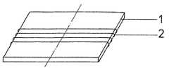
- FIG. 1A plate-shaped rectangular design of a magnet core with a winding
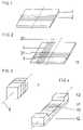
- FIG. 2A corresponding magnet core with two windings
- FIG. 3A bar-shaped magnet core with two windings
- FIG. 4A bar-shaped magnet core with an in-built winding and pole shoes
- FIG. 5A magnet core with recess
- FIG. 6An application of the antenna arrangement with two magnet cores.
- the soft magnetic componentmay comprise an amorphous or a nano-crystalline material.
- the soft magnetic componentmay comprise particles which are individually insulated with a surface layer.
- the particle sizecan be less than 2 mm.
- the particle thicknesscan be less than 0.5 mm.
- the surface of the particlescan be oxidized or plastic coated.
- the plastic componentmay comprise thermoplastic or duroplastic which can be processed with a casting resin technology.
- the antenna formed by the magnet core and windingmay have a quality more than 50 in the frequency range from 20 kHz to 150 kHz.
- the magnet corecan be loaded with a magnetic flow of at least 20 ⁇ Wb.
- the antennamay comprise several windings on the same magnet core, wherein the longitudinal axes of the windings are arranged at an angle greater than 0° to one another.
- the antennamay comprise several magnet cores that carry windings, wherein the radiation properties of the individual magnet cores are shaped and/or aligned differently.
- at least one of the magnet coresmay have a recess for accommodating electronic components.
- Yet another embodimentis directed to a method of using an antenna for inductive power transmission, wherein the antenna comprises a magnet core and a winding for use in the inductive power transmission, wherein the magnet core contains a soft magnetic component made of finely divided particles and a plastic component as the composite material and wherein the magnet core has an effective initial permeability ranging from 20 to 200 as well as a saturation induction higher than 0.6 T.
- the methodmay be used for inductive power transmission between a stationary device and a mobile device fitted with an inductive receiver. In an embodiment, the method may be used for charging the power stores in the mobile devices. In an embodiment, the method may be used for inductive power transmission from a mobile device to a stationary device.
- Yet another embodimentis directed to a method for operating an antenna comprising a plurality of magnet cores each carrying at least one winding, wherein the radiation properties of the individual magnet cores are shaped and/or aligned differently, wherein each magnet core contains a soft magnetic component made of finely divided particles and a plastic component as the composite material and wherein each magnet core has an effective initial permeability ranging from 20 to 200 as well as a saturation induction higher than 0.6 T, wherein the method may comprise the step of controlling different windings in a simultaneously phased manner or in an alternating manner.
- Yet another embodimentis directed to a method for operating an antenna comprising a magnet core having a plurality of winding for use in the inductive power transmission, wherein longitudinal axes of the windings are arranged at an angle greater than 0° to one another, and wherein the magnet core contains a soft magnetic component made of finely divided particles and a plastic component as the composite material and wherein the magnet core has an effective initial permeability ranging from 20 to 200 as well as a saturation induction higher than 0.6 T, wherein the method comprises the step of controlling different windings in a simultaneously phased manner or in an alternating manner.
- the magnet corecontains a soft magnetic component made from finely distributed particles and a plastic component as the composite material; the magnet core has an initial permeability between 20 and 200 and a saturation induction of >0.6 T.
- the soft magnetic componentis made up of the flakes of a nano-crystalline material as mentioned above.
- This componenthas a saturation magnetization of approx. 1 to 1.6 T and permeability>30,000.
- the magnetic circuitis broken because of the microscopic gaps between the flakes and a lower effective permeability of 30 to 100 is achieved at a high quality and constancy of temperature.
- a high flow densityis achieved, higher than 0.6 T, typically also higher than 0.9 T.
- a favorable property of the soft magnetic component of the magnet coreis that the particles are electrically insulated with a surface layer. This can be, for example, a plastic layer or the result of surface oxidation.
- the particle sizecan be less than 2 mm, whereby the particle thickness can be less than 0.5 mm. Because of this form of the particles, there are very little magnetic losses and thus, a very high quality of antennae is achieved.
- Thermoplastics or duroplasticssuch as polyamide, polyacrylate, polyacetate, polyimide or epoxy resin processed with the casting resin technology can be used as the plastic component, depending upon the required mechanical and thermal properties.
- the antenna arrangementhas a bar or a plate with a winding as the magnet core. Definite core cross-sections are necessary so that the arrangement can be used for an effective power transmission. If an average flow of at least 20 ⁇ Wb is attained in the core, an induction of 400 mT is achieved for a cross-section of 0.5 cm 2 . This corresponds to approximately half of the cross-section required for the use of a soft ferrite.
- the coil lengthshould be greater than the diameter of the winding so that the magnet core can be effectively used for increasing the flow.
- An important property of the material used as per this inventionis the mechanical immunity to impacts and vibrations and flexibility in shaping during the production and/or subsequent flexibility. Because of its magnetic properties, the material used as per this invention has a small size and can thus, be used in several areas of application due to cost, space and design reasons.
- windingsare arranged on the same magnet core, whereby the longitudinal axes of the windings are at an angle of >0°, e.g. 90° to one another.
- the windingscan be controlled simultaneously, in a phased manner or in an alternating manner, so that inductive power transmission to the receiver can take place in different positions.
- This inventionis based on different operating methods of the antenna arrangement with intermittent functioning of the different windings and/or the aforementioned dephased simultaneous control of the different windings.
- the antenna arrangement as per this inventioncan be space-saving, it might also be logical to provide for a recess within a magnet core, in which electronic components, e.g. the control circuit of the antenna arrangement, can be accommodated.
- the flow within the magnet corewill hardly be influenced by such recesses, provided they are not too large.
- the antenna arrangementcan be pre-fabricated with the control circuit and easily incorporated as an integral unit in the device.
- FIG. 1shows a two-dimensional magnet core 1 with a winding 2 , whereby the dimensions of the magnet core can be, e.g. 20 ⁇ 10 ⁇ 0.2 cm.
- the area of the coreis as big as the target place (to be covered) of the receiver.
- FIG. 2shows a combination of two perpendicular windings 3 , 4 on a magnet core 5 , which is almost designed as a quadratic plate. Both the windings can be controlled alternately or in a simultaneously dephased manner.
- the entire arrangementcan be flexible, as shown in FIG. 1 or 2 .
- this componentis more immune to fracture than e.g. an arrangement with ferrite core or a core made from any other material that is usually used.
- the arrangement with a bar-shaped magnet core as shown in FIG. 3is particularly suitable for the transmission of power to a mobile receiver, whereby the direction of movement as well as the antenna of the receiver is parallel to the longitudinal axis of the winding 7 .
- FIG. 6shows two different magnet cores 8 , 9 ; each has a separate winding and their longitudinal axes are perpendicular so as to allow different flow densities and radiation properties. This is an alternative to the design shown in FIG. 2 , which has several windings on a single magnet core.
- FIG. 4shows an arrangement, in which the winding 10 is integrated in a magnetic body 11 , as if it is passing through the magnet core itself 11 and the lower part of the magnet core 11 shown in FIG. 4 forms a yoke, which shorts the magnetic flow on the lower side.
- This along with the pole shoes 12 , 13gives a screening effect in one direction (downward) as well as a good radiation in the upward direction.
- the casting method described in WO 0191141 A1is particularly suitable for making such an arrangement, whereby the winding can also be cast while preparing the magnet core.
- FIG. 5shows a recess 15 in the magnet core 14 , where components of an electronic circuit, e.g. for controlling the winding 16 , can be accommodated.
- FIG. 6shows an example of application of the antenna arrangement with a mobile communication terminal unit as per this invention—such as a mobile phone or a cordless phone 17 , which has a receiver for inductive coupling with the antenna arrangement 18 (not described in detail).
- the antenna arrangement 18has a housing 19 , which accommodates both the magnet cores 8 , 9 ; each of these magnet cores has a winding and enable inductive power transmission to the receiver in the terminal unit 17 .
- a capacitor or accumulatoris also integrated in the terminal unit 17 for storing the transmitted power.
- the described antenna arrangementis specially meant for power transmission, the same arrangement can also be used for transmitting back information and/or a signal, which is possibly either transmitted in an inductive manner (whereby a changeover must take place between transmission and reception) or by evaluating the power drawn by the receiver.
- the inventioncan also be used for power transmission from a mobile device to a stationary device, e.g. in the track system for transmitting signals and/or power from a device fixed on a vehicle to a stationary sensor in a control room/signal cabin for monitoring the traffic.
Landscapes
- Soft Magnetic Materials (AREA)
- Details Of Aerials (AREA)
- Near-Field Transmission Systems (AREA)
Abstract
Description
This application is a continuation of co-pending International Application No. PCT/EP2005/005271 filed May 13, 2005, which designates the United States, and claims priority to Germanapplication number DE 10 2004 023 815.4 filed May 13, 2004.
The invention refers to an antenna arrangement with an open magnet core and a coil.
The invention has been made in the field of magnetic field antennae used for inductive power transmission. Principally, it is possible to transmit power and information via electric or magnetic dipoles. In this process, electromagnetic waves or mostly electric or magnetic fields are generated depending upon the control circuit. It would be advantageous if no electromagnetic waves are radiated and if only magnetic fields are generated; this would avoid the influence on the organic web around the antenna. Another advantage would be that relatively high energies will be transmitted to a magnetic antenna without a galvanic coupling because of the radiation of magnetic fields and/or inductive coupling. The effect of such a coupling is restricted to a very small area less than approx. Im. In spite of this, there are several application possibilities for such a transmission.
Apart from the commonly used soft ferrites, most of the known soft magnetic powder composite materials can be used as pressed magnet cores. For example, these can be made up of iron powder. With magnet cores of such type, an effective permeability ranging from 10 to 30 can be achieved. Corresponding saturation inductions can range from 1.0 to 1.4 T. Apart from this, powder composite materials made from soft magnetic crystalline iron-aluminum-silicone alloys and iron-nickel alloys are known; application frequencies of more than 100 kHz can be achieved with these.
A disadvantage of such composite materials and ferrites is that the pressing technologies only allow simple geometric forms and that the resultant magnet cores are relatively brittle and likely to break. Also, the corresponding magnetic properties are very much dependent upon the temperature, which makes the use of resonant circuits more difficult.
According to DE 19846781 A1, magnet cores are known, which are formed with the injection casting method from plastic (which can be injection cast) and a nano-crystalline alloy.
Corresponding nano-crystalline alloys are also described in, for example, EP 0271657 A2 and EP 0455113 A2. Such alloys are manufactured in the form of thin alloy strips, for example, with the quick-setting technology. These alloys are initially amorphous and are hence, subjected to a heat treatment so that a nano-crystalline structure can be obtained. Such alloys can be ground to alloy powders with particle size less than 2 mm. Usually, these so-called flakes have a thickness ranging from 0.01 to 0.04 mm and width and length ranging from 0.04 to 1 mm per particle. With the help of plastics, these flakes can be processed to form composite materials, whereby saturation magnetizations of more than 0.5 Tesla and permeability ranging from 10 to 200 can be obtained. A method of forming such magnet cores is described in WO 0191141 A1.
In EP 0762535 A1, there are antennae made up of soft magnetic powder composite materials, e.g. amorphous alloys, for transponders. Such antennae are used for exchanging information. They ensure a fail-safe exchange of information over an area of several meters as well as less interference with metallic objects in the vicinity of the antennae.
This invention is based on providing an antenna arrangement for the use of inductive power transmission.
This invention aims at an effective power transmission in the near field area and a reliable functioning irrespective of the exact positioning of the antenna arrangement against the receiver, to which the inductive power transmission must take place. For this, certain magnetic properties, a sufficient flow with appropriate radiation in particular, are necessary for the antenna arrangement.
With the help of a type compliant antenna arrangement, outputs ranging from approx. 1 W to 100 W must be transmitted from a transmitter to the receiver over a distance of approx. 0.5 to 50 cm. Such transmissions can be used, for example, in devices that have to be occasionally or constantly supplied power in a wireless manner. Because of the exclusive inductive coupling, a frequency range of 10 kHz to 150 kHz is particularly suitable due to the availability of this frequency band and the dimensional marginal conditions. Also, a magnetic flow of at least 20 μWb must be realized in the magnet core.
Since such antennae, as they are used in this antenna arrangement, mostly represent the inductive part of a resonant circuit, a high antenna quality of at least 50, preferably also 100 in the area of the operating frequency, is desirable for optimizing the power radiation. Besides, a temperature-dependent permeability between 30 and 200 is essential for an optimum flow. When the permeability is high, the directionality of the flow in the core is so good that a very little flow is given out from the core laterally and the field intensity along the core, i.e. in the receiving area, is extremely inhomogeneous.
The object of this invention cannot be satisfactorily resolved with the known magnetic arrangements, magnet cores and materials.
This object can be achieved by an antenna arrangement comprising a magnet core and a winding for use in the inductive power transmission, wherein the magnet core contains a soft magnetic component made of finely divided particles and a plastic component as the composite material and wherein the magnet core has an effective initial permeability ranging from 20 to 200 as well as a saturation induction higher than 0.6 T.
The invention is explained in detail below with the help of design examples shown in the figures in the drawing:
In an embodiment, the soft magnetic component may comprise an amorphous or a nano-crystalline material. In an embodiment, the soft magnetic component may comprise particles which are individually insulated with a surface layer. In an embodiment, the particle size can be less than 2 mm. In an embodiment, the particle thickness can be less than 0.5 mm. In an embodiment, the surface of the particles can be oxidized or plastic coated. In an embodiment, the plastic component may comprise thermoplastic or duroplastic which can be processed with a casting resin technology. In an embodiment, the antenna formed by the magnet core and winding may have a quality more than 50 in the frequency range from 20 kHz to 150 kHz. In an embodiment, the magnet core can be loaded with a magnetic flow of at least 20 μWb. In an embodiment, the antenna may comprise several windings on the same magnet core, wherein the longitudinal axes of the windings are arranged at an angle greater than 0° to one another. In an embodiment, the antenna may comprise several magnet cores that carry windings, wherein the radiation properties of the individual magnet cores are shaped and/or aligned differently. In an embodiment, at least one of the magnet cores may have a recess for accommodating electronic components.
Yet another embodiment is directed to a method of using an antenna for inductive power transmission, wherein the antenna comprises a magnet core and a winding for use in the inductive power transmission, wherein the magnet core contains a soft magnetic component made of finely divided particles and a plastic component as the composite material and wherein the magnet core has an effective initial permeability ranging from 20 to 200 as well as a saturation induction higher than 0.6 T.
In an embodiment, the method may be used for inductive power transmission between a stationary device and a mobile device fitted with an inductive receiver. In an embodiment, the method may be used for charging the power stores in the mobile devices. In an embodiment, the method may be used for inductive power transmission from a mobile device to a stationary device.
Yet another embodiment is directed to a method for operating an antenna comprising a plurality of magnet cores each carrying at least one winding, wherein the radiation properties of the individual magnet cores are shaped and/or aligned differently, wherein each magnet core contains a soft magnetic component made of finely divided particles and a plastic component as the composite material and wherein each magnet core has an effective initial permeability ranging from 20 to 200 as well as a saturation induction higher than 0.6 T, wherein the method may comprise the step of controlling different windings in a simultaneously phased manner or in an alternating manner.
Yet another embodiment is directed to a method for operating an antenna comprising a magnet core having a plurality of winding for use in the inductive power transmission, wherein longitudinal axes of the windings are arranged at an angle greater than 0° to one another, and wherein the magnet core contains a soft magnetic component made of finely divided particles and a plastic component as the composite material and wherein the magnet core has an effective initial permeability ranging from 20 to 200 as well as a saturation induction higher than 0.6 T, wherein the method comprises the step of controlling different windings in a simultaneously phased manner or in an alternating manner.
According to the invention, the magnet core contains a soft magnetic component made from finely distributed particles and a plastic component as the composite material; the magnet core has an initial permeability between 20 and 200 and a saturation induction of >0.6 T.
An advantage is that, the soft magnetic component is made up of the flakes of a nano-crystalline material as mentioned above. This component has a saturation magnetization of approx. 1 to 1.6 T and permeability>30,000. By mixing a plastic component, the magnetic circuit is broken because of the microscopic gaps between the flakes and a lower effective permeability of 30 to 100 is achieved at a high quality and constancy of temperature. However, a high flow density is achieved, higher than 0.6 T, typically also higher than 0.9 T. A favorable property of the soft magnetic component of the magnet core is that the particles are electrically insulated with a surface layer. This can be, for example, a plastic layer or the result of surface oxidation. The particle size can be less than 2 mm, whereby the particle thickness can be less than 0.5 mm. Because of this form of the particles, there are very little magnetic losses and thus, a very high quality of antennae is achieved. The mechanical properties—fracture toughness, flexibility and temperature dependability—can be adapted according to the type and proportion of plastic used.
Thermoplastics or duroplastics such as polyamide, polyacrylate, polyacetate, polyimide or epoxy resin processed with the casting resin technology can be used as the plastic component, depending upon the required mechanical and thermal properties.
In the simplest design, the antenna arrangement has a bar or a plate with a winding as the magnet core. Definite core cross-sections are necessary so that the arrangement can be used for an effective power transmission. If an average flow of at least 20 μWb is attained in the core, an induction of 400 mT is achieved for a cross-section of 0.5 cm2. This corresponds to approximately half of the cross-section required for the use of a soft ferrite.
In this case, the coil length should be greater than the diameter of the winding so that the magnet core can be effectively used for increasing the flow. An important property of the material used as per this invention is the mechanical immunity to impacts and vibrations and flexibility in shaping during the production and/or subsequent flexibility. Because of its magnetic properties, the material used as per this invention has a small size and can thus, be used in several areas of application due to cost, space and design reasons.
For achieving the desired radiation properties and/or flow of the antenna arrangement, it can be advantageous if several windings are arranged on the same magnet core, whereby the longitudinal axes of the windings are at an angle of >0°, e.g. 90° to one another. The windings can be controlled simultaneously, in a phased manner or in an alternating manner, so that inductive power transmission to the receiver can take place in different positions. Thus, power transmission becomes more reliable and immune as regards the relative positioning of the transmitter and receiver. This invention is based on different operating methods of the antenna arrangement with intermittent functioning of the different windings and/or the aforementioned dephased simultaneous control of the different windings.
To achieve a high acceptance as regards the positioning of the transmitters and receivers, it is possible to have several windings on different magnet cores of the given type, whereby the radiation property of the individual magnet cores is shaped or adjusted differently. Also, this helps in increasing the optimum positioning range of a receiver, to which the power is transmitted.
Since the antenna arrangement as per this invention can be space-saving, it might also be logical to provide for a recess within a magnet core, in which electronic components, e.g. the control circuit of the antenna arrangement, can be accommodated. The flow within the magnet core will hardly be influenced by such recesses, provided they are not too large. Besides, the antenna arrangement can be pre-fabricated with the control circuit and easily incorporated as an integral unit in the device.
If the correct plastic component is selected, the entire arrangement can be flexible, as shown inFIG. 1 or2. In any case, this component is more immune to fracture than e.g. an arrangement with ferrite core or a core made from any other material that is usually used.
The arrangement with a bar-shaped magnet core as shown inFIG. 3 is particularly suitable for the transmission of power to a mobile receiver, whereby the direction of movement as well as the antenna of the receiver is parallel to the longitudinal axis of the winding7.
The casting method described in WO 0191141 A1 is particularly suitable for making such an arrangement, whereby the winding can also be cast while preparing the magnet core.
Although the described antenna arrangement is specially meant for power transmission, the same arrangement can also be used for transmitting back information and/or a signal, which is possibly either transmitted in an inductive manner (whereby a changeover must take place between transmission and reception) or by evaluating the power drawn by the receiver.
The invention can also be used for power transmission from a mobile device to a stationary device, e.g. in the track system for transmitting signals and/or power from a device fixed on a vehicle to a stationary sensor in a control room/signal cabin for monitoring the traffic.
Claims (19)
1. An antenna arrangement comprising an elongated magnet core and a cylindrical coil wound around the core, with a longitudinal axis of the coil parallel a length axis of the core, wherein the antenna is configured to transmit power inductively to one or more receivers positioned in a distance of about 0.5 cm to about 50 cm in any direction around the antenna arrangement, wherein the magnet core contains a soft magnetic component made of finely divided particles and a plastic component as the composite material and wherein the magnet core has an effective initial permeability ranging between 30 and 100 as well as a saturation induction higher than 0.6 T.
2. The antenna according toclaim 1 , wherein the soft magnetic component comprises an amorphous or a nano-crystalline material.
3. The antenna according toclaim 1 , wherein the soft magnetic component comprises particles which are individually insulated with a surface layer.
4. The antenna according toclaim 3 , wherein the surface of the particles is oxidized or plastic coated.
5. The antenna according toclaim 3 , wherein the particle size is less than 2 mm.
6. The antenna according toclaim 3 , wherein the particle thickness is less than 0.5 mm.
7. The antenna according toclaim 1 , wherein the particle size is less than 2 mm.
8. The antenna according toclaim 1 , wherein the particle thickness is less than 0.5 mm.
9. The antenna according toclaim 1 , wherein the plastic component comprises thermoplastic or duroplastic which can be processed with a casting resin technology.
10. The antenna according toclaim 1 , wherein the antenna formed by the magnet core and winding has a quality parameter Q more than 50 in the frequency range from 20 kHz to 150 kHz.
11. The antenna according toclaim 1 , wherein the magnet core can be loaded with a magnetic flux of at least 20 μWb.
12. An antenna system comprising a plurality of antennas according toclaim 1 , wherein the magnet cores of the several antennas each carry a winding, wherein the radiation properties of the individual magnet cores are shaped and/or aligned differently.
13. The antenna according toclaim 12 , wherein at least one of the magnet cores has a recess for accommodating electronic components.
14. The antenna according toclaim 1 , wherein at least one of the magnet cores has a recess for accommodating electronic components.
15. An antenna arrangement comprising a magnet core and a cylindrical coil comprising several windings wound around the core, wherein the antenna is configured to transmit power inductively to one or more receivers positioned in a distance of about 0.5 cm to about 50 cm in any direction around the antenna arrangement, wherein the magnet core contains a soft magnetic component made of finely divided particles and a plastic component as the composite material and wherein the magnet core has an effective initial permeability ranging between 30 and 100 as well as a saturation induction higher than 0.6 T wherein the longitudinal axes of the windings are arranged at an angle greater than 0° to one another.
16. A method of using an antenna for inductive power transmission, comprising the steps of: providing an elongated magnet core with a soft magnetic component made of finely divided particles and a plastic component as the composite material, wherein the magnet core has an effective initial permeability ranging between 30 and 100 as well as a saturation induction higher than 0.6 T;
winding a cylindrical coil around said magnet core with a longitudinal axis of the coil parallel a length axis of the core; and
transmitting power inductively by means of said antenna to a receiver over a distance of about 0.5 cm to about 50 cm.
17. The method according toclaim 16 for inductive power transmission between a stationary device and a mobile device fitted with an inductive receiver.
18. The method according toclaim 17 for charging the power stores in the mobile devices.
19. The method according toclaim 16 for inductive power transmission from a mobile device to a stationary device.
Applications Claiming Priority (4)
| Application Number | Priority Date | Filing Date | Title |
|---|---|---|---|
| DE102004023815.4 | 2004-05-13 | ||
| DE102004023815ADE102004023815A1 (en) | 2004-05-13 | 2004-05-13 | Antenna arrangement and use of the antenna arrangement |
| DE102004023815 | 2004-05-13 | ||
| PCT/EP2005/005271WO2005112192A1 (en) | 2004-05-13 | 2005-05-13 | Antenna arrangement for inductive energy transmission and use of the antenna arrangement |
Related Parent Applications (1)
| Application Number | Title | Priority Date | Filing Date |
|---|---|---|---|
| PCT/EP2005/005271ContinuationWO2005112192A1 (en) | 2004-05-13 | 2005-05-13 | Antenna arrangement for inductive energy transmission and use of the antenna arrangement |
Publications (2)
| Publication Number | Publication Date |
|---|---|
| US20070126650A1 US20070126650A1 (en) | 2007-06-07 |
| US7545337B2true US7545337B2 (en) | 2009-06-09 |
Family
ID=34967320
Family Applications (1)
| Application Number | Title | Priority Date | Filing Date |
|---|---|---|---|
| US11/559,171Expired - Fee RelatedUS7545337B2 (en) | 2004-05-13 | 2006-11-13 | Antenna arrangement for inductive power transmission and use of the antenna arrangement |
Country Status (5)
| Country | Link |
|---|---|
| US (1) | US7545337B2 (en) |
| EP (1) | EP1745527B1 (en) |
| JP (1) | JP2007537637A (en) |
| DE (1) | DE102004023815A1 (en) |
| WO (1) | WO2005112192A1 (en) |
Cited By (79)
| Publication number | Priority date | Publication date | Assignee | Title |
|---|---|---|---|---|
| US20070115192A1 (en)* | 2005-11-18 | 2007-05-24 | Omron Automotive Electronics, Inc. | Key fob having LF single dimension tranceive antenna and two-dimension receive antenna |
| US20090009418A1 (en)* | 2007-07-03 | 2009-01-08 | Masin Joseph V | Miniature transponders |
| US20100133920A1 (en)* | 2005-07-12 | 2010-06-03 | Joannopoulos John D | Wireless energy transfer across a distance to a moving device |
| US20100259110A1 (en)* | 2008-09-27 | 2010-10-14 | Kurs Andre B | Resonator optimizations for wireless energy transfer |
| US20110095618A1 (en)* | 2008-09-27 | 2011-04-28 | Schatz David A | Wireless energy transfer using repeater resonators |
| US20120091949A1 (en)* | 2008-09-27 | 2012-04-19 | Campanella Andrew J | Wireless energy transfer for energizing power tools |
| US8669676B2 (en) | 2008-09-27 | 2014-03-11 | Witricity Corporation | Wireless energy transfer across variable distances using field shaping with magnetic materials to improve the coupling factor |
| US8692412B2 (en) | 2008-09-27 | 2014-04-08 | Witricity Corporation | Temperature compensation in a wireless transfer system |
| US8723366B2 (en) | 2008-09-27 | 2014-05-13 | Witricity Corporation | Wireless energy transfer resonator enclosures |
| US8772973B2 (en) | 2008-09-27 | 2014-07-08 | Witricity Corporation | Integrated resonator-shield structures |
| US8836172B2 (en) | 2008-10-01 | 2014-09-16 | Massachusetts Institute Of Technology | Efficient near-field wireless energy transfer using adiabatic system variations |
| US8847548B2 (en) | 2008-09-27 | 2014-09-30 | Witricity Corporation | Wireless energy transfer for implantable devices |
| US8875086B2 (en) | 2011-11-04 | 2014-10-28 | Witricity Corporation | Wireless energy transfer modeling tool |
| US8901778B2 (en) | 2008-09-27 | 2014-12-02 | Witricity Corporation | Wireless energy transfer with variable size resonators for implanted medical devices |
| US8901779B2 (en) | 2008-09-27 | 2014-12-02 | Witricity Corporation | Wireless energy transfer with resonator arrays for medical applications |
| US8907531B2 (en) | 2008-09-27 | 2014-12-09 | Witricity Corporation | Wireless energy transfer with variable size resonators for medical applications |
| US8912687B2 (en) | 2008-09-27 | 2014-12-16 | Witricity Corporation | Secure wireless energy transfer for vehicle applications |
| US8922066B2 (en) | 2008-09-27 | 2014-12-30 | Witricity Corporation | Wireless energy transfer with multi resonator arrays for vehicle applications |
| US8928276B2 (en) | 2008-09-27 | 2015-01-06 | Witricity Corporation | Integrated repeaters for cell phone applications |
| US8933594B2 (en) | 2008-09-27 | 2015-01-13 | Witricity Corporation | Wireless energy transfer for vehicles |
| US8937408B2 (en) | 2008-09-27 | 2015-01-20 | Witricity Corporation | Wireless energy transfer for medical applications |
| US8947186B2 (en) | 2008-09-27 | 2015-02-03 | Witricity Corporation | Wireless energy transfer resonator thermal management |
| US8946938B2 (en) | 2008-09-27 | 2015-02-03 | Witricity Corporation | Safety systems for wireless energy transfer in vehicle applications |
| US8957549B2 (en) | 2008-09-27 | 2015-02-17 | Witricity Corporation | Tunable wireless energy transfer for in-vehicle applications |
| US8963488B2 (en) | 2008-09-27 | 2015-02-24 | Witricity Corporation | Position insensitive wireless charging |
| US9035499B2 (en) | 2008-09-27 | 2015-05-19 | Witricity Corporation | Wireless energy transfer for photovoltaic panels |
| US9065423B2 (en) | 2008-09-27 | 2015-06-23 | Witricity Corporation | Wireless energy distribution system |
| US9093853B2 (en) | 2008-09-27 | 2015-07-28 | Witricity Corporation | Flexible resonator attachment |
| US9095729B2 (en) | 2007-06-01 | 2015-08-04 | Witricity Corporation | Wireless power harvesting and transmission with heterogeneous signals |
| US9105959B2 (en) | 2008-09-27 | 2015-08-11 | Witricity Corporation | Resonator enclosure |
| US9106203B2 (en) | 2008-09-27 | 2015-08-11 | Witricity Corporation | Secure wireless energy transfer in medical applications |
| US9160203B2 (en) | 2008-09-27 | 2015-10-13 | Witricity Corporation | Wireless powered television |
| US9184595B2 (en) | 2008-09-27 | 2015-11-10 | Witricity Corporation | Wireless energy transfer in lossy environments |
| US9246336B2 (en) | 2008-09-27 | 2016-01-26 | Witricity Corporation | Resonator optimizations for wireless energy transfer |
| US9287607B2 (en) | 2012-07-31 | 2016-03-15 | Witricity Corporation | Resonator fine tuning |
| US9306635B2 (en) | 2012-01-26 | 2016-04-05 | Witricity Corporation | Wireless energy transfer with reduced fields |
| US9318922B2 (en) | 2008-09-27 | 2016-04-19 | Witricity Corporation | Mechanically removable wireless power vehicle seat assembly |
| US9318257B2 (en) | 2011-10-18 | 2016-04-19 | Witricity Corporation | Wireless energy transfer for packaging |
| US9343922B2 (en) | 2012-06-27 | 2016-05-17 | Witricity Corporation | Wireless energy transfer for rechargeable batteries |
| US9369182B2 (en) | 2008-09-27 | 2016-06-14 | Witricity Corporation | Wireless energy transfer using variable size resonators and system monitoring |
| US9384885B2 (en) | 2011-08-04 | 2016-07-05 | Witricity Corporation | Tunable wireless power architectures |
| US9396867B2 (en) | 2008-09-27 | 2016-07-19 | Witricity Corporation | Integrated resonator-shield structures |
| US9404954B2 (en) | 2012-10-19 | 2016-08-02 | Witricity Corporation | Foreign object detection in wireless energy transfer systems |
| US9421388B2 (en) | 2007-06-01 | 2016-08-23 | Witricity Corporation | Power generation for implantable devices |
| US9442172B2 (en) | 2011-09-09 | 2016-09-13 | Witricity Corporation | Foreign object detection in wireless energy transfer systems |
| US9444520B2 (en) | 2008-09-27 | 2016-09-13 | Witricity Corporation | Wireless energy transfer converters |
| US9444265B2 (en) | 2005-07-12 | 2016-09-13 | Massachusetts Institute Of Technology | Wireless energy transfer |
| US9449757B2 (en) | 2012-11-16 | 2016-09-20 | Witricity Corporation | Systems and methods for wireless power system with improved performance and/or ease of use |
| US9515494B2 (en) | 2008-09-27 | 2016-12-06 | Witricity Corporation | Wireless power system including impedance matching network |
| US9544683B2 (en) | 2008-09-27 | 2017-01-10 | Witricity Corporation | Wirelessly powered audio devices |
| US9595378B2 (en) | 2012-09-19 | 2017-03-14 | Witricity Corporation | Resonator enclosure |
| US9602168B2 (en) | 2010-08-31 | 2017-03-21 | Witricity Corporation | Communication in wireless energy transfer systems |
| US9601270B2 (en) | 2008-09-27 | 2017-03-21 | Witricity Corporation | Low AC resistance conductor designs |
| US9601266B2 (en) | 2008-09-27 | 2017-03-21 | Witricity Corporation | Multiple connected resonators with a single electronic circuit |
| US9744858B2 (en) | 2008-09-27 | 2017-08-29 | Witricity Corporation | System for wireless energy distribution in a vehicle |
| US9754718B2 (en) | 2008-09-27 | 2017-09-05 | Witricity Corporation | Resonator arrays for wireless energy transfer |
| US9780573B2 (en) | 2014-02-03 | 2017-10-03 | Witricity Corporation | Wirelessly charged battery system |
| US9837860B2 (en) | 2014-05-05 | 2017-12-05 | Witricity Corporation | Wireless power transmission systems for elevators |
| US9842688B2 (en) | 2014-07-08 | 2017-12-12 | Witricity Corporation | Resonator balancing in wireless power transfer systems |
| US9843217B2 (en) | 2015-01-05 | 2017-12-12 | Witricity Corporation | Wireless energy transfer for wearables |
| US9842687B2 (en) | 2014-04-17 | 2017-12-12 | Witricity Corporation | Wireless power transfer systems with shaped magnetic components |
| US9857821B2 (en) | 2013-08-14 | 2018-01-02 | Witricity Corporation | Wireless power transfer frequency adjustment |
| US9892849B2 (en) | 2014-04-17 | 2018-02-13 | Witricity Corporation | Wireless power transfer systems with shield openings |
| US9929721B2 (en) | 2015-10-14 | 2018-03-27 | Witricity Corporation | Phase and amplitude detection in wireless energy transfer systems |
| US9948145B2 (en) | 2011-07-08 | 2018-04-17 | Witricity Corporation | Wireless power transfer for a seat-vest-helmet system |
| US9954375B2 (en) | 2014-06-20 | 2018-04-24 | Witricity Corporation | Wireless power transfer systems for surfaces |
| US9952266B2 (en) | 2014-02-14 | 2018-04-24 | Witricity Corporation | Object detection for wireless energy transfer systems |
| US10018744B2 (en) | 2014-05-07 | 2018-07-10 | Witricity Corporation | Foreign object detection in wireless energy transfer systems |
| US10063110B2 (en) | 2015-10-19 | 2018-08-28 | Witricity Corporation | Foreign object detection in wireless energy transfer systems |
| US10063104B2 (en) | 2016-02-08 | 2018-08-28 | Witricity Corporation | PWM capacitor control |
| US10075019B2 (en) | 2015-11-20 | 2018-09-11 | Witricity Corporation | Voltage source isolation in wireless power transfer systems |
| US10141788B2 (en) | 2015-10-22 | 2018-11-27 | Witricity Corporation | Dynamic tuning in wireless energy transfer systems |
| US10218224B2 (en) | 2008-09-27 | 2019-02-26 | Witricity Corporation | Tunable wireless energy transfer systems |
| US10236942B2 (en) | 2016-02-11 | 2019-03-19 | Samsung Electronics Co., Ltd. | Electronic device having loop antenna |
| US10248899B2 (en) | 2015-10-06 | 2019-04-02 | Witricity Corporation | RFID tag and transponder detection in wireless energy transfer systems |
| US10263473B2 (en) | 2016-02-02 | 2019-04-16 | Witricity Corporation | Controlling wireless power transfer systems |
| US10424976B2 (en) | 2011-09-12 | 2019-09-24 | Witricity Corporation | Reconfigurable control architectures and algorithms for electric vehicle wireless energy transfer systems |
| US10574091B2 (en) | 2014-07-08 | 2020-02-25 | Witricity Corporation | Enclosures for high power wireless power transfer systems |
| US11031818B2 (en) | 2017-06-29 | 2021-06-08 | Witricity Corporation | Protection and control of wireless power systems |
Families Citing this family (22)
| Publication number | Priority date | Publication date | Assignee | Title |
|---|---|---|---|---|
| DE102004023815A1 (en) | 2004-05-13 | 2005-12-08 | Vacuumschmelze Gmbh & Co. Kg | Antenna arrangement and use of the antenna arrangement |
| US8447234B2 (en) | 2006-01-18 | 2013-05-21 | Qualcomm Incorporated | Method and system for powering an electronic device via a wireless link |
| US9130602B2 (en) | 2006-01-18 | 2015-09-08 | Qualcomm Incorporated | Method and apparatus for delivering energy to an electrical or electronic device via a wireless link |
| GB2440571A (en)* | 2006-08-01 | 2008-02-06 | Splashpower Ltd | Drive for an inductive coupling with a changing magnetic field direction |
| US9774086B2 (en) | 2007-03-02 | 2017-09-26 | Qualcomm Incorporated | Wireless power apparatus and methods |
| US8378523B2 (en) | 2007-03-02 | 2013-02-19 | Qualcomm Incorporated | Transmitters and receivers for wireless energy transfer |
| US8482157B2 (en) | 2007-03-02 | 2013-07-09 | Qualcomm Incorporated | Increasing the Q factor of a resonator |
| US9124120B2 (en) | 2007-06-11 | 2015-09-01 | Qualcomm Incorporated | Wireless power system and proximity effects |
| WO2009036405A1 (en) | 2007-09-13 | 2009-03-19 | Nigelpower, Llc | Maximizing power yield from wireless power magnetic resonators |
| JP5362733B2 (en) | 2007-10-11 | 2013-12-11 | クゥアルコム・インコーポレイテッド | Wireless power transfer using a magneto-mechanical system |
| US8629576B2 (en) | 2008-03-28 | 2014-01-14 | Qualcomm Incorporated | Tuning and gain control in electro-magnetic power systems |
| EP3179640A1 (en)* | 2008-09-27 | 2017-06-14 | WiTricity Corporation | Wireless energy transfer systems |
| US9008574B2 (en)* | 2009-09-14 | 2015-04-14 | Qualcomm Incorporated | Focused antenna, multi-purpose antenna, and methods related thereto |
| JP5639606B2 (en)* | 2012-02-27 | 2014-12-10 | 三智商事株式会社 | Wireless IC tag |
| US8929810B2 (en) | 2012-04-23 | 2015-01-06 | Qualcomm Incorporated | Methods and apparatus for improving NFC connection through device positioning |
| DE102013104059B8 (en)* | 2013-04-22 | 2024-09-19 | Infineon Technologies Ag | Antenna arrangement and communication device |
| US9601267B2 (en) | 2013-07-03 | 2017-03-21 | Qualcomm Incorporated | Wireless power transmitter with a plurality of magnetic oscillators |
| DE102013113244A1 (en)* | 2013-11-29 | 2015-06-03 | Paul Vahle Gmbh & Co. Kg | Coil for an inductive energy transfer system |
| US10074888B2 (en)* | 2015-04-03 | 2018-09-11 | NXT-ID, Inc. | Accordion antenna structure |
| DE102015111038B4 (en)* | 2015-07-08 | 2021-05-06 | Infineon Technologies Ag | A vertical ferrite antenna with prefabricated connection components |
| US20180123227A1 (en)* | 2016-10-31 | 2018-05-03 | Hoi Luen Electrical Manufacturer Company Limited | Power Transmitting Antenna and Method of Production |
| DE112019003280A5 (en) | 2018-06-29 | 2021-03-18 | Brusa Elektronik Ag | Devices for contactless inductive charging of an electrical energy store |
Citations (14)
| Publication number | Priority date | Publication date | Assignee | Title |
|---|---|---|---|---|
| US3949388A (en)* | 1972-11-13 | 1976-04-06 | Monitron Industries, Inc. | Physiological sensor and transmitter |
| EP0271657A2 (en) | 1986-12-15 | 1988-06-22 | Hitachi Metals, Ltd. | Fe-base soft magnetic alloy and method of producing same |
| EP0455113A2 (en) | 1990-04-24 | 1991-11-06 | Alps Electric Co., Ltd. | Fe based soft magnetic alloy, magnetic material containing same, and magnetic apparatus using the magnetic materials |
| EP0762535A1 (en) | 1995-08-22 | 1997-03-12 | Mitsubishi Materials Corporation | Antenna for transponder and transponder |
| DE19718423A1 (en) | 1997-04-30 | 1998-11-05 | Siemens Ag | Portable signal receiver |
| DE19846781A1 (en) | 1998-10-10 | 2000-04-13 | Ald Vacuum Techn Ag | Method and apparatus for manufacturing precision castings by centrifugal casting |
| WO2001091141A1 (en) | 2000-05-19 | 2001-11-29 | Vacuumschmelze Gmbh & Co. Kg | Inductive component and method for the production thereof |
| WO2002101793A2 (en) | 2001-06-12 | 2002-12-19 | Applied Materials, Inc. | Systems and methods for calibrating integrated inspection tools |
| WO2002101763A1 (en) | 2001-06-08 | 2002-12-19 | Vacuumschmelze Gmbh | Inductive component and method for producing the same |
| US6630831B2 (en)* | 2000-09-02 | 2003-10-07 | Em-Tech Sensors Llc | Measurements of electrical properties through non magneticially permeable metals using directed magnetic beams and magnetic lenses |
| US20030210106A1 (en) | 2002-05-13 | 2003-11-13 | Splashpower Limited, A Company Incorporated In The Uk | Contact-less power transfer |
| US6825751B1 (en)* | 1998-12-31 | 2004-11-30 | Casio Computer Co., Ltd. | Data communication apparatus, wristwatch type electronic device, and authentication system |
| EP1496568A1 (en) | 2003-07-05 | 2005-01-12 | Kaschke KG GmbH & Co. | Transponder coil for wireless vehicle key entry systems |
| WO2005112192A1 (en) | 2004-05-13 | 2005-11-24 | Vacuumschmelze Gmbh & Co. Kg | Antenna arrangement for inductive energy transmission and use of the antenna arrangement |
Family Cites Families (1)
| Publication number | Priority date | Publication date | Assignee | Title |
|---|---|---|---|---|
| US6827557B2 (en)* | 2001-01-05 | 2004-12-07 | Humanelecs Co., Ltd. | Amorphous alloy powder core and nano-crystal alloy powder core having good high frequency properties and methods of manufacturing the same |
- 2004
- 2004-05-13DEDE102004023815Apatent/DE102004023815A1/ennot_activeCeased
- 2005
- 2005-05-13WOPCT/EP2005/005271patent/WO2005112192A1/enactiveApplication Filing
- 2005-05-13EPEP05741826.1Apatent/EP1745527B1/ennot_activeExpired - Lifetime
- 2005-05-13JPJP2007512117Apatent/JP2007537637A/enactivePending
- 2006
- 2006-11-13USUS11/559,171patent/US7545337B2/ennot_activeExpired - Fee Related
Patent Citations (24)
| Publication number | Priority date | Publication date | Assignee | Title |
|---|---|---|---|---|
| US3949388A (en)* | 1972-11-13 | 1976-04-06 | Monitron Industries, Inc. | Physiological sensor and transmitter |
| US5160379A (en) | 1986-12-15 | 1992-11-03 | Hitachi Metals, Ltd. | Fe-base soft magnetic alloy and method of producing same |
| US4881989A (en) | 1986-12-15 | 1989-11-21 | Hitachi Metals, Ltd. | Fe-base soft magnetic alloy and method of producing same |
| EP0271657A2 (en) | 1986-12-15 | 1988-06-22 | Hitachi Metals, Ltd. | Fe-base soft magnetic alloy and method of producing same |
| EP0455113A2 (en) | 1990-04-24 | 1991-11-06 | Alps Electric Co., Ltd. | Fe based soft magnetic alloy, magnetic material containing same, and magnetic apparatus using the magnetic materials |
| DE69600910T2 (en) | 1995-08-22 | 1999-07-29 | Mitsubishi Materials Corp., Tokio/Tokyo | Antenna for a transponder and a transponder |
| US6930646B2 (en) | 1995-08-22 | 2005-08-16 | Mitsubishi Materials Corporation | Transponder and antenna |
| EP0762535A1 (en) | 1995-08-22 | 1997-03-12 | Mitsubishi Materials Corporation | Antenna for transponder and transponder |
| DE19718423A1 (en) | 1997-04-30 | 1998-11-05 | Siemens Ag | Portable signal receiver |
| DE19846781A1 (en) | 1998-10-10 | 2000-04-13 | Ald Vacuum Techn Ag | Method and apparatus for manufacturing precision castings by centrifugal casting |
| US6443212B1 (en) | 1998-10-10 | 2002-09-03 | Ald Vacuum Technologies Ag | Method and apparatus for the production of precision castings by centrifugal casting |
| US6825751B1 (en)* | 1998-12-31 | 2004-11-30 | Casio Computer Co., Ltd. | Data communication apparatus, wristwatch type electronic device, and authentication system |
| WO2001091141A1 (en) | 2000-05-19 | 2001-11-29 | Vacuumschmelze Gmbh & Co. Kg | Inductive component and method for the production thereof |
| US7265651B2 (en) | 2000-05-19 | 2007-09-04 | Vacuumschmelze Gmbh & Co. Kg | Inductive component and method for the production thereof |
| US20030156000A1 (en) | 2000-05-19 | 2003-08-21 | Markus Brunner | Inductive component and method for the production thereof |
| US6630831B2 (en)* | 2000-09-02 | 2003-10-07 | Em-Tech Sensors Llc | Measurements of electrical properties through non magneticially permeable metals using directed magnetic beams and magnetic lenses |
| WO2002101763A1 (en) | 2001-06-08 | 2002-12-19 | Vacuumschmelze Gmbh | Inductive component and method for producing the same |
| US20040183643A1 (en) | 2001-06-08 | 2004-09-23 | Markus Brunner | Inductive component and method for producing the same |
| WO2002101793A2 (en) | 2001-06-12 | 2002-12-19 | Applied Materials, Inc. | Systems and methods for calibrating integrated inspection tools |
| US6906495B2 (en) | 2002-05-13 | 2005-06-14 | Splashpower Limited | Contact-less power transfer |
| US20030210106A1 (en) | 2002-05-13 | 2003-11-13 | Splashpower Limited, A Company Incorporated In The Uk | Contact-less power transfer |
| EP1496568A1 (en) | 2003-07-05 | 2005-01-12 | Kaschke KG GmbH & Co. | Transponder coil for wireless vehicle key entry systems |
| WO2005112192A1 (en) | 2004-05-13 | 2005-11-24 | Vacuumschmelze Gmbh & Co. Kg | Antenna arrangement for inductive energy transmission and use of the antenna arrangement |
| US20070126650A1 (en) | 2004-05-13 | 2007-06-07 | Wulf Guenther | Antenna Arrangement For Inductive Power Transmission And Use Of The Antenna Arrangement |
Non-Patent Citations (3)
| Title |
|---|
| International Search Report and Written Opinion for International Application No. PCT/EP2005/005271 (10 pages), May 13, 2005. |
| International Search Report; PCT/EP2005/005271; pp. 10. |
| Notification of Transmittal of Copies of Translation of the International Preliminary Report on Patentability of International Application No. PCT/EP2005/005271 (9 pages), Dec. 14, 2006. |
Cited By (160)
| Publication number | Priority date | Publication date | Assignee | Title |
|---|---|---|---|---|
| US9509147B2 (en) | 2005-07-12 | 2016-11-29 | Massachusetts Institute Of Technology | Wireless energy transfer |
| US9450421B2 (en) | 2005-07-12 | 2016-09-20 | Massachusetts Institute Of Technology | Wireless non-radiative energy transfer |
| US20100133920A1 (en)* | 2005-07-12 | 2010-06-03 | Joannopoulos John D | Wireless energy transfer across a distance to a moving device |
| US11685271B2 (en) | 2005-07-12 | 2023-06-27 | Massachusetts Institute Of Technology | Wireless non-radiative energy transfer |
| US9444265B2 (en) | 2005-07-12 | 2016-09-13 | Massachusetts Institute Of Technology | Wireless energy transfer |
| US11685270B2 (en) | 2005-07-12 | 2023-06-27 | Mit | Wireless energy transfer |
| US10666091B2 (en) | 2005-07-12 | 2020-05-26 | Massachusetts Institute Of Technology | Wireless non-radiative energy transfer |
| US9450422B2 (en) | 2005-07-12 | 2016-09-20 | Massachusetts Institute Of Technology | Wireless energy transfer |
| US9065286B2 (en) | 2005-07-12 | 2015-06-23 | Massachusetts Institute Of Technology | Wireless non-radiative energy transfer |
| US10141790B2 (en) | 2005-07-12 | 2018-11-27 | Massachusetts Institute Of Technology | Wireless non-radiative energy transfer |
| US10097044B2 (en) | 2005-07-12 | 2018-10-09 | Massachusetts Institute Of Technology | Wireless energy transfer |
| US8760008B2 (en) | 2005-07-12 | 2014-06-24 | Massachusetts Institute Of Technology | Wireless energy transfer over variable distances between resonators of substantially similar resonant frequencies |
| US8760007B2 (en) | 2005-07-12 | 2014-06-24 | Massachusetts Institute Of Technology | Wireless energy transfer with high-Q to more than one device |
| US8766485B2 (en) | 2005-07-12 | 2014-07-01 | Massachusetts Institute Of Technology | Wireless energy transfer over distances to a moving device |
| US8772971B2 (en) | 2005-07-12 | 2014-07-08 | Massachusetts Institute Of Technology | Wireless energy transfer across variable distances with high-Q capacitively-loaded conducting-wire loops |
| US9831722B2 (en) | 2005-07-12 | 2017-11-28 | Massachusetts Institute Of Technology | Wireless non-radiative energy transfer |
| US8772972B2 (en) | 2005-07-12 | 2014-07-08 | Massachusetts Institute Of Technology | Wireless energy transfer across a distance to a moving device |
| US8791599B2 (en) | 2005-07-12 | 2014-07-29 | Massachusetts Institute Of Technology | Wireless energy transfer to a moving device between high-Q resonators |
| US20070115192A1 (en)* | 2005-11-18 | 2007-05-24 | Omron Automotive Electronics, Inc. | Key fob having LF single dimension tranceive antenna and two-dimension receive antenna |
| US9843230B2 (en) | 2007-06-01 | 2017-12-12 | Witricity Corporation | Wireless power harvesting and transmission with heterogeneous signals |
| US10348136B2 (en) | 2007-06-01 | 2019-07-09 | Witricity Corporation | Wireless power harvesting and transmission with heterogeneous signals |
| US9943697B2 (en) | 2007-06-01 | 2018-04-17 | Witricity Corporation | Power generation for implantable devices |
| US10420951B2 (en) | 2007-06-01 | 2019-09-24 | Witricity Corporation | Power generation for implantable devices |
| US9421388B2 (en) | 2007-06-01 | 2016-08-23 | Witricity Corporation | Power generation for implantable devices |
| US9318898B2 (en) | 2007-06-01 | 2016-04-19 | Witricity Corporation | Wireless power harvesting and transmission with heterogeneous signals |
| US9101777B2 (en) | 2007-06-01 | 2015-08-11 | Witricity Corporation | Wireless power harvesting and transmission with heterogeneous signals |
| US9095729B2 (en) | 2007-06-01 | 2015-08-04 | Witricity Corporation | Wireless power harvesting and transmission with heterogeneous signals |
| US20090009418A1 (en)* | 2007-07-03 | 2009-01-08 | Masin Joseph V | Miniature transponders |
| US7825869B2 (en)* | 2007-07-03 | 2010-11-02 | Masin Joseph V | Miniature transponders |
| US9748039B2 (en) | 2008-09-27 | 2017-08-29 | Witricity Corporation | Wireless energy transfer resonator thermal management |
| US8669676B2 (en) | 2008-09-27 | 2014-03-11 | Witricity Corporation | Wireless energy transfer across variable distances using field shaping with magnetic materials to improve the coupling factor |
| US8957549B2 (en) | 2008-09-27 | 2015-02-17 | Witricity Corporation | Tunable wireless energy transfer for in-vehicle applications |
| US8963488B2 (en) | 2008-09-27 | 2015-02-24 | Witricity Corporation | Position insensitive wireless charging |
| US9035499B2 (en) | 2008-09-27 | 2015-05-19 | Witricity Corporation | Wireless energy transfer for photovoltaic panels |
| US9065423B2 (en) | 2008-09-27 | 2015-06-23 | Witricity Corporation | Wireless energy distribution system |
| US8947186B2 (en) | 2008-09-27 | 2015-02-03 | Witricity Corporation | Wireless energy transfer resonator thermal management |
| US9093853B2 (en) | 2008-09-27 | 2015-07-28 | Witricity Corporation | Flexible resonator attachment |
| US8937408B2 (en) | 2008-09-27 | 2015-01-20 | Witricity Corporation | Wireless energy transfer for medical applications |
| US9105959B2 (en) | 2008-09-27 | 2015-08-11 | Witricity Corporation | Resonator enclosure |
| US8933594B2 (en) | 2008-09-27 | 2015-01-13 | Witricity Corporation | Wireless energy transfer for vehicles |
| US9106203B2 (en) | 2008-09-27 | 2015-08-11 | Witricity Corporation | Secure wireless energy transfer in medical applications |
| US9160203B2 (en) | 2008-09-27 | 2015-10-13 | Witricity Corporation | Wireless powered television |
| US9184595B2 (en) | 2008-09-27 | 2015-11-10 | Witricity Corporation | Wireless energy transfer in lossy environments |
| US9246336B2 (en) | 2008-09-27 | 2016-01-26 | Witricity Corporation | Resonator optimizations for wireless energy transfer |
| US12263743B2 (en) | 2008-09-27 | 2025-04-01 | Witricity Corporation | Wireless power system modules |
| US11958370B2 (en) | 2008-09-27 | 2024-04-16 | Witricity Corporation | Wireless power system modules |
| US9318922B2 (en) | 2008-09-27 | 2016-04-19 | Witricity Corporation | Mechanically removable wireless power vehicle seat assembly |
| US8928276B2 (en) | 2008-09-27 | 2015-01-06 | Witricity Corporation | Integrated repeaters for cell phone applications |
| US20100259110A1 (en)* | 2008-09-27 | 2010-10-14 | Kurs Andre B | Resonator optimizations for wireless energy transfer |
| US20110095618A1 (en)* | 2008-09-27 | 2011-04-28 | Schatz David A | Wireless energy transfer using repeater resonators |
| US9369182B2 (en) | 2008-09-27 | 2016-06-14 | Witricity Corporation | Wireless energy transfer using variable size resonators and system monitoring |
| US11479132B2 (en) | 2008-09-27 | 2022-10-25 | Witricity Corporation | Wireless power transmission system enabling bidirectional energy flow |
| US9396867B2 (en) | 2008-09-27 | 2016-07-19 | Witricity Corporation | Integrated resonator-shield structures |
| US11114896B2 (en) | 2008-09-27 | 2021-09-07 | Witricity Corporation | Wireless power system modules |
| US8922066B2 (en) | 2008-09-27 | 2014-12-30 | Witricity Corporation | Wireless energy transfer with multi resonator arrays for vehicle applications |
| US11114897B2 (en) | 2008-09-27 | 2021-09-07 | Witricity Corporation | Wireless power transmission system enabling bidirectional energy flow |
| US9444520B2 (en) | 2008-09-27 | 2016-09-13 | Witricity Corporation | Wireless energy transfer converters |
| US8912687B2 (en) | 2008-09-27 | 2014-12-16 | Witricity Corporation | Secure wireless energy transfer for vehicle applications |
| US10673282B2 (en) | 2008-09-27 | 2020-06-02 | Witricity Corporation | Tunable wireless energy transfer systems |
| US8907531B2 (en) | 2008-09-27 | 2014-12-09 | Witricity Corporation | Wireless energy transfer with variable size resonators for medical applications |
| US8901779B2 (en) | 2008-09-27 | 2014-12-02 | Witricity Corporation | Wireless energy transfer with resonator arrays for medical applications |
| US20120091949A1 (en)* | 2008-09-27 | 2012-04-19 | Campanella Andrew J | Wireless energy transfer for energizing power tools |
| US9496719B2 (en) | 2008-09-27 | 2016-11-15 | Witricity Corporation | Wireless energy transfer for implantable devices |
| US8901778B2 (en) | 2008-09-27 | 2014-12-02 | Witricity Corporation | Wireless energy transfer with variable size resonators for implanted medical devices |
| US9515495B2 (en) | 2008-09-27 | 2016-12-06 | Witricity Corporation | Wireless energy transfer in lossy environments |
| US9515494B2 (en) | 2008-09-27 | 2016-12-06 | Witricity Corporation | Wireless power system including impedance matching network |
| US9544683B2 (en) | 2008-09-27 | 2017-01-10 | Witricity Corporation | Wirelessly powered audio devices |
| US9577436B2 (en) | 2008-09-27 | 2017-02-21 | Witricity Corporation | Wireless energy transfer for implantable devices |
| US9584189B2 (en) | 2008-09-27 | 2017-02-28 | Witricity Corporation | Wireless energy transfer using variable size resonators and system monitoring |
| US9596005B2 (en) | 2008-09-27 | 2017-03-14 | Witricity Corporation | Wireless energy transfer using variable size resonators and systems monitoring |
| US10559980B2 (en) | 2008-09-27 | 2020-02-11 | Witricity Corporation | Signaling in wireless power systems |
| US10536034B2 (en) | 2008-09-27 | 2020-01-14 | Witricity Corporation | Wireless energy transfer resonator thermal management |
| US9601270B2 (en) | 2008-09-27 | 2017-03-21 | Witricity Corporation | Low AC resistance conductor designs |
| US9601266B2 (en) | 2008-09-27 | 2017-03-21 | Witricity Corporation | Multiple connected resonators with a single electronic circuit |
| US9601261B2 (en) | 2008-09-27 | 2017-03-21 | Witricity Corporation | Wireless energy transfer using repeater resonators |
| US9662161B2 (en) | 2008-09-27 | 2017-05-30 | Witricity Corporation | Wireless energy transfer for medical applications |
| US9698607B2 (en) | 2008-09-27 | 2017-07-04 | Witricity Corporation | Secure wireless energy transfer |
| US9711991B2 (en) | 2008-09-27 | 2017-07-18 | Witricity Corporation | Wireless energy transfer converters |
| US9742204B2 (en) | 2008-09-27 | 2017-08-22 | Witricity Corporation | Wireless energy transfer in lossy environments |
| US9744858B2 (en) | 2008-09-27 | 2017-08-29 | Witricity Corporation | System for wireless energy distribution in a vehicle |
| US10446317B2 (en) | 2008-09-27 | 2019-10-15 | Witricity Corporation | Object and motion detection in wireless power transfer systems |
| US9754718B2 (en) | 2008-09-27 | 2017-09-05 | Witricity Corporation | Resonator arrays for wireless energy transfer |
| US8946938B2 (en) | 2008-09-27 | 2015-02-03 | Witricity Corporation | Safety systems for wireless energy transfer in vehicle applications |
| US9780605B2 (en) | 2008-09-27 | 2017-10-03 | Witricity Corporation | Wireless power system with associated impedance matching network |
| US10410789B2 (en) | 2008-09-27 | 2019-09-10 | Witricity Corporation | Integrated resonator-shield structures |
| US9806541B2 (en) | 2008-09-27 | 2017-10-31 | Witricity Corporation | Flexible resonator attachment |
| US8692412B2 (en) | 2008-09-27 | 2014-04-08 | Witricity Corporation | Temperature compensation in a wireless transfer system |
| US8847548B2 (en) | 2008-09-27 | 2014-09-30 | Witricity Corporation | Wireless energy transfer for implantable devices |
| US10340745B2 (en) | 2008-09-27 | 2019-07-02 | Witricity Corporation | Wireless power sources and devices |
| US10300800B2 (en) | 2008-09-27 | 2019-05-28 | Witricity Corporation | Shielding in vehicle wireless power systems |
| US9843228B2 (en) | 2008-09-27 | 2017-12-12 | Witricity Corporation | Impedance matching in wireless power systems |
| US10264352B2 (en) | 2008-09-27 | 2019-04-16 | Witricity Corporation | Wirelessly powered audio devices |
| US10230243B2 (en) | 2008-09-27 | 2019-03-12 | Witricity Corporation | Flexible resonator attachment |
| US10218224B2 (en) | 2008-09-27 | 2019-02-26 | Witricity Corporation | Tunable wireless energy transfer systems |
| US8723366B2 (en) | 2008-09-27 | 2014-05-13 | Witricity Corporation | Wireless energy transfer resonator enclosures |
| US8729737B2 (en) | 2008-09-27 | 2014-05-20 | Witricity Corporation | Wireless energy transfer using repeater resonators |
| US10097011B2 (en) | 2008-09-27 | 2018-10-09 | Witricity Corporation | Wireless energy transfer for photovoltaic panels |
| US10084348B2 (en) | 2008-09-27 | 2018-09-25 | Witricity Corporation | Wireless energy transfer for implantable devices |
| US8772973B2 (en) | 2008-09-27 | 2014-07-08 | Witricity Corporation | Integrated resonator-shield structures |
| US8836172B2 (en) | 2008-10-01 | 2014-09-16 | Massachusetts Institute Of Technology | Efficient near-field wireless energy transfer using adiabatic system variations |
| US9831682B2 (en) | 2008-10-01 | 2017-11-28 | Massachusetts Institute Of Technology | Efficient near-field wireless energy transfer using adiabatic system variations |
| US9602168B2 (en) | 2010-08-31 | 2017-03-21 | Witricity Corporation | Communication in wireless energy transfer systems |
| US9948145B2 (en) | 2011-07-08 | 2018-04-17 | Witricity Corporation | Wireless power transfer for a seat-vest-helmet system |
| US9787141B2 (en) | 2011-08-04 | 2017-10-10 | Witricity Corporation | Tunable wireless power architectures |
| US10734842B2 (en) | 2011-08-04 | 2020-08-04 | Witricity Corporation | Tunable wireless power architectures |
| US11621585B2 (en) | 2011-08-04 | 2023-04-04 | Witricity Corporation | Tunable wireless power architectures |
| US9384885B2 (en) | 2011-08-04 | 2016-07-05 | Witricity Corporation | Tunable wireless power architectures |
| US10778047B2 (en) | 2011-09-09 | 2020-09-15 | Witricity Corporation | Foreign object detection in wireless energy transfer systems |
| US9442172B2 (en) | 2011-09-09 | 2016-09-13 | Witricity Corporation | Foreign object detection in wireless energy transfer systems |
| US10027184B2 (en) | 2011-09-09 | 2018-07-17 | Witricity Corporation | Foreign object detection in wireless energy transfer systems |
| US11097618B2 (en) | 2011-09-12 | 2021-08-24 | Witricity Corporation | Reconfigurable control architectures and algorithms for electric vehicle wireless energy transfer systems |
| US10424976B2 (en) | 2011-09-12 | 2019-09-24 | Witricity Corporation | Reconfigurable control architectures and algorithms for electric vehicle wireless energy transfer systems |
| US9318257B2 (en) | 2011-10-18 | 2016-04-19 | Witricity Corporation | Wireless energy transfer for packaging |
| US8875086B2 (en) | 2011-11-04 | 2014-10-28 | Witricity Corporation | Wireless energy transfer modeling tool |
| US9306635B2 (en) | 2012-01-26 | 2016-04-05 | Witricity Corporation | Wireless energy transfer with reduced fields |
| US9343922B2 (en) | 2012-06-27 | 2016-05-17 | Witricity Corporation | Wireless energy transfer for rechargeable batteries |
| US10158251B2 (en) | 2012-06-27 | 2018-12-18 | Witricity Corporation | Wireless energy transfer for rechargeable batteries |
| US9287607B2 (en) | 2012-07-31 | 2016-03-15 | Witricity Corporation | Resonator fine tuning |
| US9595378B2 (en) | 2012-09-19 | 2017-03-14 | Witricity Corporation | Resonator enclosure |
| US10686337B2 (en) | 2012-10-19 | 2020-06-16 | Witricity Corporation | Foreign object detection in wireless energy transfer systems |
| US9465064B2 (en) | 2012-10-19 | 2016-10-11 | Witricity Corporation | Foreign object detection in wireless energy transfer systems |
| US10211681B2 (en) | 2012-10-19 | 2019-02-19 | Witricity Corporation | Foreign object detection in wireless energy transfer systems |
| US9404954B2 (en) | 2012-10-19 | 2016-08-02 | Witricity Corporation | Foreign object detection in wireless energy transfer systems |
| US10186372B2 (en) | 2012-11-16 | 2019-01-22 | Witricity Corporation | Systems and methods for wireless power system with improved performance and/or ease of use |
| US9842684B2 (en) | 2012-11-16 | 2017-12-12 | Witricity Corporation | Systems and methods for wireless power system with improved performance and/or ease of use |
| US9449757B2 (en) | 2012-11-16 | 2016-09-20 | Witricity Corporation | Systems and methods for wireless power system with improved performance and/or ease of use |
| US11112814B2 (en) | 2013-08-14 | 2021-09-07 | Witricity Corporation | Impedance adjustment in wireless power transmission systems and methods |
| US9857821B2 (en) | 2013-08-14 | 2018-01-02 | Witricity Corporation | Wireless power transfer frequency adjustment |
| US11720133B2 (en) | 2013-08-14 | 2023-08-08 | Witricity Corporation | Impedance adjustment in wireless power transmission systems and methods |
| US9780573B2 (en) | 2014-02-03 | 2017-10-03 | Witricity Corporation | Wirelessly charged battery system |
| US9952266B2 (en) | 2014-02-14 | 2018-04-24 | Witricity Corporation | Object detection for wireless energy transfer systems |
| US10186373B2 (en) | 2014-04-17 | 2019-01-22 | Witricity Corporation | Wireless power transfer systems with shield openings |
| US9842687B2 (en) | 2014-04-17 | 2017-12-12 | Witricity Corporation | Wireless power transfer systems with shaped magnetic components |
| US9892849B2 (en) | 2014-04-17 | 2018-02-13 | Witricity Corporation | Wireless power transfer systems with shield openings |
| US9837860B2 (en) | 2014-05-05 | 2017-12-05 | Witricity Corporation | Wireless power transmission systems for elevators |
| US10018744B2 (en) | 2014-05-07 | 2018-07-10 | Witricity Corporation | Foreign object detection in wireless energy transfer systems |
| US10371848B2 (en) | 2014-05-07 | 2019-08-06 | Witricity Corporation | Foreign object detection in wireless energy transfer systems |
| US10923921B2 (en) | 2014-06-20 | 2021-02-16 | Witricity Corporation | Wireless power transfer systems for surfaces |
| US11637458B2 (en) | 2014-06-20 | 2023-04-25 | Witricity Corporation | Wireless power transfer systems for surfaces |
| US9954375B2 (en) | 2014-06-20 | 2018-04-24 | Witricity Corporation | Wireless power transfer systems for surfaces |
| US10574091B2 (en) | 2014-07-08 | 2020-02-25 | Witricity Corporation | Enclosures for high power wireless power transfer systems |
| US9842688B2 (en) | 2014-07-08 | 2017-12-12 | Witricity Corporation | Resonator balancing in wireless power transfer systems |
| US9843217B2 (en) | 2015-01-05 | 2017-12-12 | Witricity Corporation | Wireless energy transfer for wearables |
| US10248899B2 (en) | 2015-10-06 | 2019-04-02 | Witricity Corporation | RFID tag and transponder detection in wireless energy transfer systems |
| US9929721B2 (en) | 2015-10-14 | 2018-03-27 | Witricity Corporation | Phase and amplitude detection in wireless energy transfer systems |
| US10063110B2 (en) | 2015-10-19 | 2018-08-28 | Witricity Corporation | Foreign object detection in wireless energy transfer systems |
| US10651689B2 (en) | 2015-10-22 | 2020-05-12 | Witricity Corporation | Dynamic tuning in wireless energy transfer systems |
| US10651688B2 (en) | 2015-10-22 | 2020-05-12 | Witricity Corporation | Dynamic tuning in wireless energy transfer systems |
| US10141788B2 (en) | 2015-10-22 | 2018-11-27 | Witricity Corporation | Dynamic tuning in wireless energy transfer systems |
| US10075019B2 (en) | 2015-11-20 | 2018-09-11 | Witricity Corporation | Voltage source isolation in wireless power transfer systems |
| US10637292B2 (en) | 2016-02-02 | 2020-04-28 | Witricity Corporation | Controlling wireless power transfer systems |
| US10263473B2 (en) | 2016-02-02 | 2019-04-16 | Witricity Corporation | Controlling wireless power transfer systems |
| US10063104B2 (en) | 2016-02-08 | 2018-08-28 | Witricity Corporation | PWM capacitor control |
| US10913368B2 (en) | 2016-02-08 | 2021-02-09 | Witricity Corporation | PWM capacitor control |
| US11807115B2 (en) | 2016-02-08 | 2023-11-07 | Witricity Corporation | PWM capacitor control |
| US10236942B2 (en) | 2016-02-11 | 2019-03-19 | Samsung Electronics Co., Ltd. | Electronic device having loop antenna |
| US11637452B2 (en) | 2017-06-29 | 2023-04-25 | Witricity Corporation | Protection and control of wireless power systems |
| US11588351B2 (en) | 2017-06-29 | 2023-02-21 | Witricity Corporation | Protection and control of wireless power systems |
| US11043848B2 (en) | 2017-06-29 | 2021-06-22 | Witricity Corporation | Protection and control of wireless power systems |
| US11031818B2 (en) | 2017-06-29 | 2021-06-08 | Witricity Corporation | Protection and control of wireless power systems |
Also Published As
| Publication number | Publication date |
|---|---|
| JP2007537637A (en) | 2007-12-20 |
| WO2005112192A1 (en) | 2005-11-24 |
| DE102004023815A1 (en) | 2005-12-08 |
| EP1745527B1 (en) | 2013-04-17 |
| EP1745527A1 (en) | 2007-01-24 |
| WO2005112192A9 (en) | 2006-02-09 |
| US20070126650A1 (en) | 2007-06-07 |
Similar Documents
| Publication | Publication Date | Title |
|---|---|---|
| US7545337B2 (en) | Antenna arrangement for inductive power transmission and use of the antenna arrangement | |
| KR101827721B1 (en) | Antenna module for car | |
| KR101707883B1 (en) | Hybrid Type Magnetic Field Shield Sheet and Antenna Module Using the Same | |
| US7511679B2 (en) | Antenna, and radio timepiece using the same, keyless entry system, and RFID system | |
| US20130033408A1 (en) | Three-axis antenna and core assembly used therein | |
| US9369185B2 (en) | Method and apparatus for inductive coupling utilizing an amorphous metal barrier | |
| EP3471198B1 (en) | Antenna for a hearing assistance device | |
| EP3471201B1 (en) | Antenna for a hearing assistance device | |
| KR102085646B1 (en) | wireless power transmission device | |
| EP2752943A1 (en) | Soft magnetic layer, receiving antenna, and wireless power receiving apparatus comprising the same | |
| CN105493347B (en) | Electronic equipment | |
| KR20150068400A (en) | Composite coil module and portable apparatus | |
| KR20110134430A (en) | Compound RF tag and the tool which installed the compound RF tag | |
| KR102067549B1 (en) | Electronic device and coil module | |
| CA2645771A1 (en) | Inductive device including permanent magnet and associated methods | |
| KR101394508B1 (en) | Soft magnetism sheet, wireless power receiving apparatus and wireless charging method of the same | |
| EP2911243B1 (en) | Electronic device and antenna device | |
| US20150325365A1 (en) | Soft magnetic alloy, wireless power transmitting apparatus and wireless power receiving apparatus comprising the same | |
| US20230369894A1 (en) | Wireless charging device and transportation means comprising same | |
| KR20220136692A (en) | Heat dissipation antenna for wireless power transmission, heat dissipation antenna module for wireless power transmission module and electronic device comprising the same | |
| KR101453465B1 (en) | Soft magnetism sheet, wireless power receiving apparatus and wireless charging method of the same | |
| EP3698431B1 (en) | Antenna for a hearing assistance device | |
| EP3471199B1 (en) | Antenna for a hearing assistance device | |
| JP2018019502A (en) | Power transmission / reception antenna system | |
| KR101941530B1 (en) | Antenna unit that have hybrid type antenna pattern connection structure |
Legal Events
| Date | Code | Title | Description |
|---|---|---|---|
| AS | Assignment | Owner name:VACUUMSCMELZE GMBH & CO. KG, GERMANY Free format text:ASSIGNMENT OF ASSIGNORS INTEREST;ASSIGNOR:GUENTHER, WULF;REEL/FRAME:019405/0830 Effective date:20070126 | |
| FPAY | Fee payment | Year of fee payment:4 | |
| REMI | Maintenance fee reminder mailed | ||
| LAPS | Lapse for failure to pay maintenance fees | ||
| STCH | Information on status: patent discontinuation | Free format text:PATENT EXPIRED DUE TO NONPAYMENT OF MAINTENANCE FEES UNDER 37 CFR 1.362 | |
| FP | Lapsed due to failure to pay maintenance fee | Effective date:20170609 |