US7544056B2 - Valve-gated injection molding nozzle having an annular flow - Google Patents
Valve-gated injection molding nozzle having an annular flowDownload PDFInfo
- Publication number
- US7544056B2 US7544056B2US11/609,152US60915206AUS7544056B2US 7544056 B2US7544056 B2US 7544056B2US 60915206 AUS60915206 AUS 60915206AUS 7544056 B2US7544056 B2US 7544056B2
- Authority
- US
- United States
- Prior art keywords
- nozzle
- melt channel
- liner
- melt
- downstream portion
- Prior art date
- Legal status (The legal status is an assumption and is not a legal conclusion. Google has not performed a legal analysis and makes no representation as to the accuracy of the status listed.)
- Active, expires
Links
Images


Classifications
- B—PERFORMING OPERATIONS; TRANSPORTING
- B29—WORKING OF PLASTICS; WORKING OF SUBSTANCES IN A PLASTIC STATE IN GENERAL
- B29C—SHAPING OR JOINING OF PLASTICS; SHAPING OF MATERIAL IN A PLASTIC STATE, NOT OTHERWISE PROVIDED FOR; AFTER-TREATMENT OF THE SHAPED PRODUCTS, e.g. REPAIRING
- B29C45/00—Injection moulding, i.e. forcing the required volume of moulding material through a nozzle into a closed mould; Apparatus therefor
- B29C45/17—Component parts, details or accessories; Auxiliary operations
- B29C45/26—Moulds
- B29C45/27—Sprue channels ; Runner channels or runner nozzles
- B29C45/28—Closure devices therefor
- B29C45/2806—Closure devices therefor consisting of needle valve systems
- B—PERFORMING OPERATIONS; TRANSPORTING
- B29—WORKING OF PLASTICS; WORKING OF SUBSTANCES IN A PLASTIC STATE IN GENERAL
- B29C—SHAPING OR JOINING OF PLASTICS; SHAPING OF MATERIAL IN A PLASTIC STATE, NOT OTHERWISE PROVIDED FOR; AFTER-TREATMENT OF THE SHAPED PRODUCTS, e.g. REPAIRING
- B29C45/00—Injection moulding, i.e. forcing the required volume of moulding material through a nozzle into a closed mould; Apparatus therefor
- B29C45/17—Component parts, details or accessories; Auxiliary operations
- B29C45/26—Moulds
- B29C45/27—Sprue channels ; Runner channels or runner nozzles
- B29C45/278—Nozzle tips
- B—PERFORMING OPERATIONS; TRANSPORTING
- B29—WORKING OF PLASTICS; WORKING OF SUBSTANCES IN A PLASTIC STATE IN GENERAL
- B29C—SHAPING OR JOINING OF PLASTICS; SHAPING OF MATERIAL IN A PLASTIC STATE, NOT OTHERWISE PROVIDED FOR; AFTER-TREATMENT OF THE SHAPED PRODUCTS, e.g. REPAIRING
- B29C45/00—Injection moulding, i.e. forcing the required volume of moulding material through a nozzle into a closed mould; Apparatus therefor
- B29C45/17—Component parts, details or accessories; Auxiliary operations
- B29C45/26—Moulds
- B29C45/27—Sprue channels ; Runner channels or runner nozzles
- B29C45/30—Flow control means disposed within the sprue channel, e.g. "torpedo" construction
- B29C2045/308—Mixing or stirring devices
Definitions
- the present inventionis related to a nozzle for an injection molding apparatus.
- Injection molding systemsgenerally include an injection molding unit, an injection manifold and one or more hot runner nozzles for receiving melt from the manifold and transferring/distributing the melt to one or more mold cavities.
- Hot runner systemsoffer the choice between thermal gating and valve gating.
- Valve gatingis used in applications where the esthetic appearance of finished molded part is important, because it provides a better gate vestige on the part than thermal gating.
- One problem with valve pin gatingis premature wear of the pin and the nozzle as a result of misalignment of the valve pin; this in turn may cause leakage and poor cosmetic part quality.
- valve-gated hot runner nozzlesare not suitable for molding parts that require improved strength or higher esthetic merits. This is because the valve pin behaves as an obstruction in the flow of the melt through the nozzle and towards the mold cavity. The valve pin splits the melt flow and this creates undesirable flow lines that are visible or weakens the finished molded part.
- a first color molten materialmust be flushed from the system so that a second color molten material may be run through the injection molding machine to produce parts of different color.
- Residue material from the first/subsequent color of the molten materialconventionally causes numerous shots of injection molded products to be defective because they have an undesirable blend of two colors of molten material. It is common for a substantial number of products to be defective in this way requiring multiple injection cycles to clear the runner system before useable products are formed.
- unidirectional molecular orientation and weld/flow linescan be a potential cause for weakness in the structural integrity, dimensional accuracy, or cause unwanted birefringence of molded products.
- a system and methodthat substantially reduces residue of molten material in an injection molding machine, while also providing a method that improves valve pin alignment in the nozzle and gate area. Additionally or alternatively what is needed is a system and method for eliminating or substantially reducing unidirectional molecular orientation and/or weld/flow lines in a molded product caused by the valve gating device, such as a valve pin.
- An embodiment according to the present inventionincludes a valve-gated nozzle for an injection molding apparatus.
- the nozzlehas a nozzle body with a nozzle melt channel and a nozzle liner having a first melt channel in fluid communication with the nozzle melt channel.
- the nozzle linerincludes two or more second melt channels in fluid communication with the first melt channel, such that each second melt channel has a second melt channel axis that is at an angle with respect to a longitudinal axis of the first melt channel.
- the nozzle lineralso includes a downstream portion that extends from proximate the outlets of the second melt channels to a downstream end of the nozzle liner.
- a retaining devicesecures the nozzle liner with respect to the nozzle body and includes a downstream portion with an inner surface, such that an annular melt channel is formed between the outer surface of the nozzle liner downstream portion and the inner surface of the retaining device downstream portion.
- at least one of the outer surface of the nozzle liner downstream portion and the inner surface of the retaining device downstream portionincludes a groove.
- the nozzlehas a valve pin that slidingly extends within the nozzle melt channel and the first melt channel of the nozzle liner to selectively open a mold gate, wherein the downstream portion of the nozzle liner has a valve pin alignment bore for aligning the valve pin with the mold gate.
- FIG. 1illustrates a sectional view of an injection molding system in which the present invention may be utilized.
- FIG. 2illustrates a side sectional view of a portion A of FIG. 1 according to an embodiment of the present invention.
- FIG. 2Aillustrates a side sectional view of a portion A of FIG. 1 according to another embodiment of the present invention.
- FIG. 3illustrates a side sectional view of a valve-gated nozzle arrangement according to another embodiment of the present invention.
- FIG. 4is an enlarged view of a portion of the nozzle in FIG. 3 .
- FIG. 5illustrates a cross-sectional view of the nozzle liner and retainer of the nozzle of FIG. 3 taken along line D-D.
- FIG. 6is a schematic sectional view of a portion of a nozzle liner and retaining device according to another embodiment of the present invention.
- FIG. 7illustrates a sectional view of a valve-gated nozzle arrangement according to another embodiment of the present invention.
- FIG. 8illustrates a side view of a nozzle liner 740 of FIG. 7 .
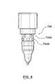
- FIG. 9illustrates a sectional view of a valve-gated nozzle arrangement according to another embodiment of the present invention.
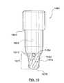
- FIG. 10illustrates a side view of a nozzle liner 1040 according to another embodiment of the present invention.
- FIG. 11illustrates a side view in partial section of a tip retainer 1142 according to another embodiment of the present invention.
- FIG. 12illustrates a side sectional view of a portion A of FIG. 1 according to another embodiment of the present invention that includes the nozzle liner of FIG. 10 .
- Embodiments according to the present inventionprovide a valve-gated nozzle in an injection molding machine that allows for an improved flow of a molten material into a mold cavity, which can substantially reduce or eliminate flow lines in an injected molded product.
- thisis accomplished through use of a valve-gated nozzle having a nozzle body with a nozzle melt channel in fluid communication with a nozzle liner, and which can also be in fluid communication with a manifold melt channel.
- the nozzle linerincludes a first melt channel in fluid communication with the nozzle melt channel and one or more release melt channels between the first melt channel and an annular melt channel.
- the annular melt channelis formed between a retaining device and the nozzle liner.
- the annular melt channelincludes a decompression chamber in fluid communication with respective ones of the release melt channels and a compression chamber between the decompression chamber and a mold cavity.
- a pressure differenceresults between the respective release melt channels and the decompression chamber and between the decompression chamber and the compression chamber that acts to blend the molten material in the nozzle liner area more quickly and efficiently than current systems, such that it enters a mold cavity without flow lines, i.e., weld lines.
- the material used for the nozzle lineris a high thermally conductive material.
- the nozzle linerhas corrosion and abrasion resistance, e.g. wear resistance.
- a plurality of exit holes or bores, i.e., release or second tip melt channels,are located at a point where an outer surface of the nozzle liner separates from an inner surface of the retaining device. The exit holes or bores are oriented from the first tip melt channel outwardly towards the retaining device. The flow rate required from the hot runner system to fill the mold cavity is used to determine the diameter and the number of the exit holes.
- an outer or exterior surface of the nozzle lineris designed in conjunction with an inner or interior surface of the retaining device to have the annular melt channel therebetween, with some embodiments including decompression and compression chambers.
- the nozzle liner exit holes or boresopen to the decompression chamber, which creates a circular flow of the molten material around the nozzle liner in order to mix/blend the molten material. Then, under the growing pressure of the molten material in the decompression chamber, the molten material flows through the compression chamber, which acts as a pressure regulator and shear generator. This leads to an annular flow, which flushes out and further blends the molten material to eliminate flow lines and/or ease color change.
- the compression of the molten materialoccurs up to a seal area at a downstream portion of the retaining device and a mold gate area.
- a reduction of the annular surface of the nozzle linerincreases the flow speed and shear rate of the melt, which can result in an increase of the relative temperature of the molten material and hot runner components, e.g., the retaining device and the nozzle liner. This facilitates the re-melting and flushing out of any solidified melt material in contact with the mold left behind from the previous shot, which reduces the number of shots required to achieve complete color change.
- the nozzle linermay act as a guide for the valve pin in order to avoid any deflection due to pin closing and/or pressure against movement of the valve pin.
- FIG. 1illustrates an injection molding apparatus 100 in which the present invention may be utilized.
- Apparatus 100includes a manifold 102 , a plurality of nozzles 104 , and a mold plate 106 .
- Manifold 102has a plurality of manifold melt channels 108 extending therethrough from an inlet 110 to a plurality of outlets 112 .
- Manifold 102includes a heater 114 for heating melt in the manifold melt channels 108 .
- a nozzle melt channel 116passes through a head portion 118 and a body portion 120 of nozzle 114 , extending from an inlet 122 in head portion 118 to an outlet 124 in body portion 120 .
- Head portion 118abuts against a downstream surface of manifold 102 so that one of manifold melt channel outlets 112 communicates with inlet 122 of nozzle melt channel 116 .
- Nozzle melt channel 116may be generally longitudinally centered in head and body portions 118 and 120 , i.e., melt channel 116 may extend generally along axis CL.
- Each nozzle 104includes a heater 132 that is wrapped around body portion 120 .
- Mold plate 106includes a plurality of mold cavities 126 in which injection molded articles are formed. Each mold cavity 126 receives melt through a gate 128 , which is in communication with outlet 124 from one of nozzles 104 . Mold plate 106 may be cooled by means of a fluid flowing through a plurality of cooling channels 130 , to solidify melt in mold cavities 126 , thereby forming molded articles (not shown).
- one of nozzles 104includes a valve gating element 134 .
- Valve gating element 134includes a valve pin 135 that is movable within nozzle melt channel 116 by means of an actuator 136 .
- the other one of nozzles 104is thermally gated, and thus does not include a valve pin.
- meltpasses from a melt source (not shown), through manifold inlet 110 , through manifold melt channels 108 , through nozzle melt channels 116 , through gate 128 and into mold cavities 126 .
- nozzles 104may be used with configurations of injection molding apparatus other than that shown in FIG. 1 .
- nozzles 104may be used with injection molding apparatuses having a single mold cavity.
- Nozzles 104may also be used with co-injection molding apparatuses that have a plurality of manifolds 102 .
- Nozzles 104may also be used in stack-mold machines.
- FIGS. A 2 and 2 Aillustrate a side sectional view of a portion A of the valve-gated nozzle of FIG. 1 in accordance with embodiments of the present invention and show a valve pin 235 in both its open (right half) and closed (left half) positions.
- Valve-gated nozzle 204includes a torpedo-type nozzle tip or liner 240 .
- Nozzle 204also includes a retaining device 242 .
- nozzle liner 240 and retaining device 242may function as a two-piece nozzle seal. Retaining device 242 positions and secures nozzle liner 240 within a nozzle body 220 .
- retaining device 242is engaged through threads on an outer wall 244 of retaining device 242 with complementary threads on an inner wall 246 of nozzle body 220 .
- a shoulder 248 of retaining device 242abuts a curved portion 250 of nozzle liner 240 to secure it to nozzle body 220 .
- retaining device 242may be engaged with nozzle body 220 by brazing, soldering, press fit, or any other acceptable known method.
- Nozzle liner 240transports or directs the melt from nozzle body melt channel 216 to mold cavity 226 .
- nozzle liner 240may be made from a thermally conductive material to reduce losses in the heat transferred from nozzle heater 132 to the melt within the nozzle liner first and second melt channels 252 , 254 .
- thermally conductive materials for forming nozzle liner 240include: Be—Cu(Beryllium-Copper), Beryllium-free Copper, such as AMPCO 940, TZM (Titanium/Zirconium carbide), Aluminum or Aluminum-based alloys, Nickel-Chromium alloys, such as INCONEL, Molybdenum or suitable Molybdenum alloys, H13, mold steel or steel alloys, such as AERMET 100.
- nozzle liner 240may be made from a wear resistant material.
- a material that is both thermally conductive and wear resistantis tungsten carbide. The construction of a nozzle tip from tungsten carbide is disclosed in U.S. Pat. No. 5,658,604 to Gellert et al., which is incorporated by reference herein in its entirety.
- retaining device 242may be made from a material that is less wear resistant than the material of nozzle liner 240 , because retaining device 242 may not have as much contact with an abrasive melt as a nozzle liner with an internal melt passage. Accordingly, retaining device 242 may be made from a material that is relatively easily machined for readily forming the threaded portion thereon. In another embodiment, such as certain applications with highly abrasive melt, it may be beneficial for retaining device 242 to be of a wear resistant material due to melt contact made with an inner surface of retaining device 242 within an annular melt channel 256 , which is described in more detail below.
- Retaining device 242may be made from a steel-based, a titanium-based, a ceramic-based, or other thermally insulative material to prevent heat transfer away from the melt channels.
- retaining device 242includes a sealing portion 251 that seals the air space around nozzle 204 to prevent melt from leaving the gate area.
- sealing portion 251may function as an insulating insert or insulating portion, and only sealing portion 251 may be made from a thermally insulative material, such as, titanium, a ceramic, a heat resistant polymer, such as, certain polyimides, e.g. VESPEL, and/or polyketones, e.g., polyetheretherketone (PEEK), or the like with the remainder of retaining device 242 being made of a thermally conductive material, as discussed further below.
- a thermally insulative materialsuch as, titanium, a ceramic, a heat resistant polymer, such as, certain polyimides, e.g. VESPEL, and/or polyket
- Retaining device 242is at least in part, positioned between nozzle liner along at least a portion of the length of the first and second melt channels 252 , 254 and nozzle heater 132 . As such, in some embodiments, heat flow from nozzle heater 132 to first and second melt channels 252 , 254 may be improved when retaining device 242 is made from a thermally conductive material.
- retaining device 242may be made from a thermally conductive material, such as, Copper, Be—Cu (Beryllium-Copper), Beryllium-free Copper, such as, AMPCO 940, TZM (Titanium/Zirconium carbide), Aluminum or Aluminum-based alloys, Nickel-Chromium alloys, such as INCONEL, Molybdenum or suitable Molybdenum alloys, H13, steel, mold steel or steel alloys, such as AERMET 100.
- a thermally conductive materialsuch as, Copper, Be—Cu (Beryllium-Copper), Beryllium-free Copper, such as, AMPCO 940, TZM (Titanium/Zirconium carbide), Aluminum or Aluminum-based alloys, Nickel-Chromium alloys, such as INCONEL, Molybdenum or suitable Molybdenum alloys, H13, steel, mold steel or steel alloys, such as AERMET 100.
- FIG. 2Aillustrates a mold contacting piece or insulative insert 253 positioned between retaining device 242 and mold plate 106 that may inhibit melt leakage and heat transfer from the gate area. Mold contacting piece 253 may form a seal between retaining device 242 and mold plate 106 , as well as aid in aligning nozzle 204 with respect to the gate 228 .
- mold contacting piece 253may be made from a material that is comparatively less thermally conductive than the material of nozzle liner 240 and/or retaining device 242 .
- mold contacting piece 253may be made from titanium, H13, stainless steel, mold steel, chrome steel, and certain ceramics and heat resistant polymers, such as, certain polyimides, e.g. VESPEL, and/or polyketones, e.g., polyetheretherketone (PEEK).
- Nozzle liner 240includes a first melt channel 252 having a longitudinal axis CL that is in fluid communication at an upstream end with a nozzle body melt channel 216 .
- First melt channel 252is in fluid communication at a downstream end with at least one second melt channel 254 having an axis 255 .
- longitudinal axis CL of first melt channel 252 and axis 255 of the second melt channel 254are substantially normal with respect to each other.
- substantially normalcan mean they are 90° ⁇ 10°.
- another rangeis possible based on tolerances within desired applications.
- the axis CL of first melt channel 252 and the axis 255 ′ of each of second melt channels 254 ′are at an acute angle with respect to each other.
- a valve pin alignment bore 264 of nozzle liner 240is sized to slidingly receive valve pin 235 , but not the melt from first melt channel 252 .
- Second melt channel 254is in fluid communication with an annular melt channel 256 formed between nozzle liner 240 and retaining device 242 .
- Annular melt channel 256includes a first portion 258 and a second portion 260 .
- Second melt channel 254is a release or exit channel through which the molten material flows from first melt channel 252 of nozzle liner 240 .
- Second melt channel 254can be formed as a bore or hole through a wall of nozzle liner 240 . Depending on an application and/or material make-up of nozzle liner 240 , there can be any number of release melt channels 254 .
- release melt channel 254 of nozzle liner 240is used to transmit the molten material to first portion 258 of annular melt channel 256 , which in this embodiment acts as a decompression chamber.
- a pressure of the molten materialis greater in release melt channel 254 than in decompression chamber 258 .
- the molten materialflows into second portion 260 , which acts as a compression chamber.
- a pressure of the molten material in decompression chamber 258is reduced due to the material expansion allowed within decompression chamber 258 .
- the molten materialflows into second portion or compression chamber 260 of annular melt channel 256 , which due to the restrictive configuration of second portion 260 increases a pressure of the molten material as the molten material is forced therethrough toward a mold gate 228 of a mold cavity 226 .
- the decompression chamber 258circumferentially surrounds the portion of the nozzle liner 240 through which release melt channels 254 extend such that release melt channels 254 radially discharge into the circumferential decompression chamber 258 .
- the circumference/diameter of the nozzle linermay be smaller in the area of decompression chamber 258 than the circumference/diameter of the nozzle liner in the area of compression chamber 260 , such that cross-sectional flow area through the decompression chamber 258 is greater than that of the more restrictive compression chamber 260 .
- This arrangement of annular melt channel 256balances the flow velocity and pressure of the melt exiting nozzle body melt channel 216 resulting in balanced melt flow between mold cavities 226 , which in turn provides consistent part quality between parts produced in different mold cavities.
- nozzle liner 240serves two purposes. As described above, nozzle liner 244 controls the melt flow by distributing the molten material from first melt channel 252 through release melt channels 254 , such that the flow, velocity, and/or pressure is balanced resulting in an even and balanced flow of the molten material. Nozzle liner 240 also functions as an alignment device for valve pin 235 . As such, nozzle liner 240 includes valve pin alignment bore 264 that slidingly aligns valve pin 235 with gate 228 in close proximity thereto to avoid any deflection during pin closing and pressure against movement.
- an inside surface of bore 264can be coated with a coating that aides in the movement (friction) and/or alignment of valve pin 235 .
- the coatingcan be, but is not limited to, a nickel-based material, or the like.
- a coatingcan also be implemented to improve the hardness of the nozzle liner 240 surface in contact with the valve pin 235 .
- a fit between valve pin 235 and nozzle liner bore 264does not allow melt to flow around valve pin 235 .
- a “bubble area”can be seen as a stagnant area between retaining device 242 , tip 240 , and mold gate 228 that fills with material during a first shot. The material remains stagnant and typically does not flush out between shots.
- the stagnant materialcan be used to provide insulation between nozzle liner 240 and mold plate 106 .
- Respective pressure changes in the melt between second melt channel 254 and first and second portions 258 and 260 of annular melt channel 256causes the molten material to flow between first melt channel 252 and mold cavity 226 at a higher sheer rate than in conventional nozzles, thereby mixing and maintaining melt in a molten condition to readily exit via mold gate 228 .
- thisallows a better consistency of molten material due to mixing before mold cavity 226 , thereby reducing or eliminating weld/flow lines within the molded product.
- the afore-mentioned configurationallows the previous color molten material to be flushed out of nozzle 204 substantially within very few product cycles, e.g. in approximately 1 ⁇ 4-1 ⁇ 5 the number of cycles required using a conventional nozzle arrangement complete color change may be achieved.
- FIG. 9illustrates a sectional view of a portion of a valve-gated nozzle 904 in accordance with another embodiment of the present invention.
- Many elements shown in FIG. 9are similar to those shown and described with reference to FIG. 2 , as such only the differences in structure will be discussed below.
- nozzle liner 940is retained within nozzle 904 through the threaded engagement between threads 970 formed on nozzle liner 940 and threads 972 formed on an inner surface of a front end bore of nozzle body 920 .
- Transfer seal 942is also secured within the front end bore of nozzle body 920 through threaded engagement between threads on outer wall 944 of retaining device 942 with complementary threads on inner wall 946 of nozzle body 920 .
- transfer seal 942does not retain nozzle liner 940 within nozzle body 920 , it still functions similarly to retaining device 242 by providing a sealing portion 951 as well as defining an outer surface of annular melt channel 956 .
- nozzle liner and/or retaining device 940 , 942may be coupled to nozzle body 920 via brazing or another coupling method known to one of ordinary skill in the art.
- FIGS. 3-5illustrate a valve-gated nozzle 304 for use in the injection molding apparatus of FIG. 1 according to another embodiment of the present invention.
- FIG. 4is an enlarged view of a portion of nozzle 304 in FIG. 3 .
- valve-gated nozzle 304includes a nozzle liner 340 and retaining device 342 , which may function as a two-piece nozzle seal.
- Retaining device 342positions and secures nozzle liner 340 within nozzle body 320 through threaded engagement between threads on an outer wall 344 of retaining device 342 with complementary threads on an inner wall 346 of nozzle body 320 , such that a shoulder 348 of retaining device 342 abuts a curved portion 350 of nozzle liner 340 .
- Retaining device 342includes a sealing portion 351 that provides a seal against mold plate 306 proximate mold gate 328 to prevent melt leakage.
- Nozzle liner 340includes a first melt channel 352 having a longitudinal axis CL that is in fluid communication at an upstream end with a nozzle body melt channel 316 .
- first melt channel 352is in fluid communication at a downstream end with four second melt channels 354 , two of which share a longitudinal axis 355 that is substantially normal with respect to axis CL of first melt channel 352 .
- the remaining second melt channels 354may have longitudinal axes 355 that are substantially normal to or at an acute angle with respect to axis CL.
- one or more second melt channelsmay have an axis 355 that is normal to or at an acute angle with CL.
- a number of release melt channelsis application specific, as are the parameters (sizes) of the release melt channels and the decompression chamber and compression chamber of the annular melt channel.
- Nozzle liner 340also includes a valve pin alignment bore 364 sized to slidingly receive a valve pin 335 , but not the melt, from first melt channel 352 .
- Second melt channels 354are in fluid communication with an annular melt channel 356 formed between nozzle liner 340 and retaining device 342 .
- Annular melt channel 356includes a first portion 358 and a second portion 360 that operate in the manner described above with reference to the embodiment of FIG. 2 .
- nozzle liner 340 and retaining device 342also provide the melt balancing/mixing benefit described above.
- Nozzle liner 340distributes the molten material from first melt channel 352 through release melt channels 354 , such that the flow, velocity, and/or pressure is balanced.
- nozzle liner 340also functions as an alignment device for valve pin 335 .
- nozzle liner 340includes valve pin alignment bore 364 that slidingly aligns valve pin 335 with gate 328 in close proximity thereto to avoid any deflection during pin closing and pressure against movement.
- Valve pin 335is shown in an open position in FIG. 4 .
- an inside surface of bore 364may be coated with a coating that aides in the movement and/or alignment of valve pin 335 , such as a coating of a nickel-based material, or the like.
- melt channel 316 of valve-gated nozzle 304receives a melt from manifold melt channel 308 of manifold 302 via manifold outlet 312 that abut nozzle head portion 318 .
- the meltflows through nozzle liner first and second melt channels 352 , 354 into and through annular melt channel 356 , as described above, to be delivered via nozzle outlet 324 through mold gate 328 into mold cavity 326 .
- FIG. 7illustrates a sectional view of a portion of a valve-gated nozzle 704 according to another embodiment of the present invention.
- FIG. 8illustrates a side view of a nozzle liner 740 of FIG. 7 .
- Nozzle liner 740has a plurality of release melt channels 754 A on a first level and a second plurality of release melt channels 754 B on a second level downstream from a first level.
- release melt channels 754 Aare offset with respect to release melt channels 754 B, which may be done, for example, to provide an intercrossing melt flow that may result in a substantial reduction of weld/split lines as compared to only a single release melt channel or a single level release melt channel embodiment.
- a number of release melt channels 754 A on the first levelcan be equal to or different than a number of release channels 754 B on the second level.
- FIG. 7includes all elements described above for FIGS. 2 and 4 , with the alternative nozzle liner 740 , as described above for FIG. 7 .
- release melt channels 754 A and 754 Bexit from first melt channel 752 into first portion 758 of annular melt channel 756 .
- FIG. 6is a schematic sectional view of a portion of a nozzle liner 640 and retaining device 642 according to an embodiment of the present invention.
- Nozzle liner 640includes a first melt channel 652 that feeds a melt stream into a plurality of second melt channels 654 , which in turn transfer the melt stream into an annular melt channel 656 that is defined between a nozzle liner 640 and a retaining device 642 .
- Annular melt channel 656includes a first inner diameter D 1 formed in a first portion 658 of annular melt channel 656 and a second inner diameter D 2 formed in a second portion 660 of annular melt channel 656 , wherein D 1 is smaller than D 2 .
- an outer diameter D 3 of annular melt channel 656is constant along the length of annular melt channel 656 , such that within annular melt channel 656 an annular area of first portion 658 is greater than an annular area of second portion 660 .
- Nozzle liner 640also includes a valve pin alignment bore 664 for aligning a valve pin (not shown) with a mold gate (not shown) in close proximity thereto, to avoid any deflection during pin closing.
- the retaining devicehas a substantially constant inner diameter.
- the annular melt channelincludes a first portion and a second portion.
- the first portion of the annular channelhas a first inner diameter and is in fluid communication with the nozzle liner second melt channel.
- the second portion of the annular melt channelhas a second inner diameter and is in fluid communication with the first portion of the annular melt channel and with a mold cavity.
- the second inner diameteris larger than the first inner diameter.
- FIG. 10illustrates a side view of a nozzle liner 1040 according to another embodiment of the present invention and FIG. 12 illustrates a side sectional view of a portion A of FIG. 1 that includes nozzle liner 1040 of FIG. 10 .
- Nozzle liner 1040includes a centrally located first melt channel 1052 for directing a melt stream to a plurality of second or release melt channels 1054 .
- a longitudinal axis of first melt channel 1052 and a longitudinal axis of second or release melt channel(s) 1054may be at an acute angle with respect to each other or substantially normal, i.e., 90° ⁇ 10°, with respect to each other.
- Nozzle liner 1040also includes a valve pin alignment bore 1064 for aligning a valve pin 1235 with a mold gate 1228 , as discussed above with reference to the previous embodiments.
- Nozzle liner 1040includes a curved portion 1050 that allows nozzle liner 1040 to be secured by a shoulder 1248 of a retaining device 1242 within a nozzle body 1220 .
- retaining device 1242is threadably engaged with nozzle body 1220 .
- An outer surface of a downstream portion 1077 of nozzle liner 1040provides an inner surface for an annular melt channel 1256 according to another embodiment of the present invention.
- the outer surface of annular melt channel 1256is provided by a tapered inner surface 1257 of a downstream portion 1279 of retaining device 1242 .
- Nozzle liner downstream portion 1077extends from proximate a recessed outlet 1073 of release channels 1054 to a downstream end 1078 of nozzle liner 1040 and includes one or more groove(s) 1075 in the outer surface thereof.
- An upstream end of groove 1075is adjacent to outlet 1073 of release melt channel 1054 to receive the melt stream therefrom, such that the melt stream is directed along groove 1075 within downstream portion 1077 of nozzle liner 1040 .
- grooves 1075partially curve or spiral around downstream portion 1077 of nozzle liner 1040 .
- groove or grooves 1075may run parallel to or at an acute angle with a longitudinal axis of nozzle liner 1040 within downstream portion 1077 .
- two or more grooves 1075may cross or extend in opposite directions from each other within downstream portion 1077 . Accordingly, groove(s) 1075 aid in guiding, swirling and/or mixing the melt stream emanating from release channel(s) 1054 within annular melt channel 1256 to provide a better consistency to the melt stream before it enters the mold cavity, thereby reducing or eliminating weld/flow lines within the molded product.
- release melt channel 1054 of nozzle liner 1040is used to transmit the molten material to a first portion 1258 of annular melt channel 1256 that acts as a decompression chamber due its enlarged annular area.
- a pressure of the molten materialis greater in release melt channel 1054 than in decompression chamber 1258 , as a pressure of the molten material in decompression chamber 1258 is reduced due to the material expansion allowed within the enlarged annular area.
- the molten materialflows directed by grooves 1075 into a second portion 1260 that acts as a compression chamber due to the restrictive configuration of second portion 1260 that increases a pressure of the molten material as it is forced there through and toward mold gate 1228 .
- FIG. 11illustrates a side view in partial section of a retaining device 1042 according to another embodiment of the present invention.
- An upper end or shoulder 1148 of retaining device 1142is for engaging a curved portion of a nozzle liner, such as curved portion 250 , 1050 of nozzle liners 240 , 1040 of the embodiments shown in FIGS. 2 and 10 , respectively, which in conjunction with threaded portion 1180 secures the nozzle liner to a nozzle body.
- Retaining device 1142includes a sealing portion 1151 for sealing against a mold plate proximate a mold gate during operation of the injection molding system.
- An inner surface of a downstream portion 1179 of retaining device 1142provides an outer surface for an annular melt channel according to another embodiment of the present invention.
- the inner surface of the annular melt channelis provided by an outer surface of a downstream portion of a retaining device, such as retaining device 242 , 1042 of FIGS. 2 and 10 , respectively, as discussed above with reference to the previous embodiments.
- Retaining device downstream portion 1179extends from proximate an outlet of a release channel (not shown) to an end 1182 of retaining device 1142 and includes one or more grooves 1176 in the inner surface thereof.
- An upstream end of groove 1176is for positioning proximate an outlet of a release melt channel to receive the melt stream therefrom, such that the melt stream is directed along groove 1176 within downstream portion 1179 of retaining device 1142 .
- groove(s) 1176aids in guiding, swirling and/or mixing the melt stream emanating from the release channel(s) of the nozzle liner within the annular melt channel to provide a better consistency to the melt stream before it enters a mold cavity, thereby reducing or eliminating weld/flow lines within the molded product.
- grooves 1176partially curve or spiral within downstream portion 1179 of retaining device 1142 .
- groove or grooves 1176may run parallel to or at an acute angle with a longitudinal axis of retaining device 1142 within downstream portion 1179 .
- two or more grooves 1176may cross or extend in opposite directions from each other within downstream portion 1179 .
Landscapes
- Engineering & Computer Science (AREA)
- Manufacturing & Machinery (AREA)
- Mechanical Engineering (AREA)
- Moulds For Moulding Plastics Or The Like (AREA)
Abstract
Description
Claims (32)
Priority Applications (3)
| Application Number | Priority Date | Filing Date | Title |
|---|---|---|---|
| US11/609,152US7544056B2 (en) | 2004-06-02 | 2006-12-11 | Valve-gated injection molding nozzle having an annular flow |
| DE102007059545.1ADE102007059545B4 (en) | 2006-12-11 | 2007-12-11 | Valve-controlled injection molding nozzle with a ring flow |
| CA002613909ACA2613909A1 (en) | 2006-12-11 | 2007-12-11 | Valve-gated injection molding nozzle having an annular flow |
Applications Claiming Priority (3)
| Application Number | Priority Date | Filing Date | Title |
|---|---|---|---|
| US57584204P | 2004-06-02 | 2004-06-02 | |
| US11/142,915US7364425B2 (en) | 2004-06-02 | 2005-06-02 | Valve-gated injection molding nozzle having an annular flow |
| US11/609,152US7544056B2 (en) | 2004-06-02 | 2006-12-11 | Valve-gated injection molding nozzle having an annular flow |
Related Parent Applications (1)
| Application Number | Title | Priority Date | Filing Date |
|---|---|---|---|
| US11/142,915Continuation-In-PartUS7364425B2 (en) | 2004-06-02 | 2005-06-02 | Valve-gated injection molding nozzle having an annular flow |
Publications (2)
| Publication Number | Publication Date |
|---|---|
| US20070082083A1 US20070082083A1 (en) | 2007-04-12 |
| US7544056B2true US7544056B2 (en) | 2009-06-09 |
Family
ID=39510025
Family Applications (1)
| Application Number | Title | Priority Date | Filing Date |
|---|---|---|---|
| US11/609,152Active2025-12-26US7544056B2 (en) | 2004-06-02 | 2006-12-11 | Valve-gated injection molding nozzle having an annular flow |
Country Status (3)
| Country | Link |
|---|---|
| US (1) | US7544056B2 (en) |
| CA (1) | CA2613909A1 (en) |
| DE (1) | DE102007059545B4 (en) |
Cited By (3)
| Publication number | Priority date | Publication date | Assignee | Title |
|---|---|---|---|---|
| US20120177775A1 (en)* | 2011-01-11 | 2012-07-12 | Kojima Press Industry Co., Ltd. | Torpedoes |
| US20140295014A1 (en)* | 2011-11-08 | 2014-10-02 | Husky Injection Molding Systems Ltd. | Mold-tool system having stem-guidance assembly for guiding movement of valve-stem assembly |
| US11358313B2 (en) | 2017-02-21 | 2022-06-14 | Husky Injection Molding Systems Ltd. | Co-injection hot runner nozzle |
Families Citing this family (9)
| Publication number | Priority date | Publication date | Assignee | Title |
|---|---|---|---|---|
| DE602005017444D1 (en)* | 2004-06-02 | 2009-12-17 | Mold Masters 2007 Ltd | Closure nozzle device for injection molding with an annular flow |
| US7344372B2 (en)* | 2004-06-02 | 2008-03-18 | Mold-Masters (2007) Limited | Injection molding nozzle having an annular flow tip |
| WO2006113737A2 (en)* | 2005-04-19 | 2006-10-26 | Hypertherm, Inc. | Plasma arc torch providing angular shield flow injection |
| US20140097275A1 (en)* | 2012-10-10 | 2014-04-10 | Caterpillar Inc. | Fuel injector with nozzle passages having electroless nickel coating |
| KR101936986B1 (en)* | 2015-01-28 | 2019-03-28 | 인글라스 에스피에이 | System and method for injection moulding of plastic materials |
| WO2016149258A1 (en) | 2015-03-16 | 2016-09-22 | Synventive Molding Solutions, Inc. | Nozzle configuration for purging flow channel |
| DE102017113885A1 (en)* | 2017-06-22 | 2018-12-27 | Günther Heisskanaltechnik Gmbh | Distributor device for an injection molding nozzle, injection molding nozzle with distributor device and injection molding tool with injection molding nozzle and distributor device |
| IT202000004351A1 (en)* | 2020-03-02 | 2021-09-02 | Sipa Progettazione Automaz | COMPONENT FOR NOZZLE FOR INJECTION SYSTEM TO PRODUCE PLASTIC CONTAINERS |
| WO2022075917A1 (en)* | 2020-10-07 | 2022-04-14 | Meiban International Pte Ltd | Anti-drool cold deck for high consistency silicone rubber |
Citations (49)
| Publication number | Priority date | Publication date | Assignee | Title |
|---|---|---|---|---|
| US3915358A (en) | 1974-03-01 | 1975-10-28 | Karl Hehl | Lever actuated pressure responsive injection nozzle |
| US4212625A (en) | 1978-03-14 | 1980-07-15 | Shutt George V | High speed injector for molding machines |
| US4303382A (en) | 1980-05-21 | 1981-12-01 | Gellert Jobst U | Melt spinning nozzle tip |
| US4501550A (en) | 1981-12-02 | 1985-02-26 | Shigeru Tsutsumi | Cap means for preventing resin from remaining in a mold of a runnerless injection molding apparatus |
| US4711602A (en) | 1986-07-17 | 1987-12-08 | Precision Rubber Products Corporation | Turbulent flow gate for the injection molding of tubular parts, including parisons suitable for blow molding |
| US4712990A (en) | 1983-04-13 | 1987-12-15 | American Can Company | Apparatus for injection molding and injection blow molding multi-layer articles |
| US4781572A (en) | 1987-10-09 | 1988-11-01 | Sonoco Products Company | Self-regulating gate valve assembly for injection molding apparatus |
| US4787836A (en) | 1987-06-30 | 1988-11-29 | Fairchild Industries, Inc. | Injection molding nozzle |
| US4965028A (en) | 1987-09-04 | 1990-10-23 | Galic/Maus Ventures | Method of injection molding thermoplastic through multiple gates |
| JPH04320820A (en) | 1991-04-19 | 1992-11-11 | Victor Co Of Japan Ltd | Mold device for injection molding |
| US5208052A (en) | 1991-11-18 | 1993-05-04 | Husky Injection Molding Systems Ltd. | Hot runner nozzle assembly |
| EP0546554A1 (en) | 1991-12-11 | 1993-06-16 | Jobst Ulrich Gellert | Injection molding sealing collar with a central hot tip shaft |
| US5324191A (en) | 1992-09-30 | 1994-06-28 | Husky Injection Molding Systems Ltd. | Sealed edge gate |
| US5513976A (en) | 1994-04-13 | 1996-05-07 | Caco Pacific Corporation | Nozzle for heating and passing a fluid into a mold |
| US5545028A (en) | 1994-08-16 | 1996-08-13 | Kona Corporation | Bushing tip for injection molding apparatus |
| DE19608676C1 (en) | 1996-03-06 | 1997-01-30 | Hasco Normalien Hasenclever Co | Closure nozzle for a tool mold for processing plastic masses, in particular for a plastic injection mold |
| DE19533231A1 (en) | 1995-09-08 | 1997-03-13 | Wolff Hans Martin | Hot runner nozzle for plastics injection mould |
| US5840231A (en) | 1997-08-14 | 1998-11-24 | Husky Injection Molding Systems Ltd. | Valve gate assembly |
| DE19730380A1 (en) | 1997-07-16 | 1999-01-21 | Hasco Normalien Hasenclever Co | Melt guiding method in a polymer injection nozzle |
| US5871786A (en) | 1997-04-04 | 1999-02-16 | Kona Corporation | Tip heated hot runner nozzle |
| US5879727A (en) | 1997-01-21 | 1999-03-09 | Husky Injection Molding Systems, Ltd. | Insulated modular injection nozzle system |
| US5948450A (en) | 1996-09-27 | 1999-09-07 | Dynisco Hotrunners, Inc. | Valve actuated injection molding apparatus |
| US6022210A (en) | 1995-01-31 | 2000-02-08 | Gunther Heisskanaltechnik Gmbh | Hot runner nozzle |
| JP2000167883A (en) | 1998-12-07 | 2000-06-20 | Mitsubishi Materials Corp | Valve gate type mold apparatus |
| US6089468A (en) | 1999-11-08 | 2000-07-18 | Husky Injection Molding Systems Ltd. | Nozzle tip with weld line eliminator |
| US6245278B1 (en) | 1999-06-03 | 2001-06-12 | Husky Injection Molding Systems Ltd. | Injection nozzle and method |
| US6273706B1 (en) | 1998-06-03 | 2001-08-14 | Gunther Heisskanaltechnik Gmbh | Valve nozzle having a pressure-relief means |
| DE10008722A1 (en) | 2000-02-24 | 2001-08-30 | Ewikon Heiskanalsysteme Gmbh & | Hot duct connector, e.g. for injection molding tool, includes a spring-loaded cylindrical junction piece to provide a sliding joint |
| US6302680B1 (en) | 1999-02-16 | 2001-10-16 | Mold-Masters Limited | Injection molding apparatus with removable nozzle seal |
| US6305923B1 (en) | 1998-06-12 | 2001-10-23 | Husky Injection Molding Systems Ltd. | Molding system using film heaters and/or sensors |
| US20020081348A1 (en) | 2000-12-08 | 2002-06-27 | Abdeslam Bouti | Flow deflector in an injection molding system |
| US6478567B1 (en) | 1997-02-19 | 2002-11-12 | Dollins Tool, Inc. | Nozzle assembly for injection molding |
| EP1295693A1 (en) | 2001-09-21 | 2003-03-26 | Synventive Molding Solutions B.V. | Injection moulding device with detachable nozzle tip |
| WO2003028974A1 (en) | 2001-10-03 | 2003-04-10 | Mold-Masters Limited | Tip assembly having at least three components for hot runner nozzle |
| US6609902B1 (en) | 2002-11-12 | 2003-08-26 | Husky Injection Molding Systems Ltd. | Injection molding nozzle |
| US20030209833A1 (en)* | 2000-02-29 | 2003-11-13 | Bemis Peter F. | Co-injection apparatus for injection molding |
| US6679697B2 (en) | 2000-12-08 | 2004-01-20 | Husky Injection Molding Systems Ltd. | Flow detector apparatus |
| US20040022891A1 (en) | 2002-08-02 | 2004-02-05 | Robert Sicilia | Removable heater for a hot runner nozzle |
| US20040091562A1 (en) | 2002-11-07 | 2004-05-13 | Husky Injection Molding Systems, Ltd | Apparatus for retaining a heater and thermocouple on an injection molding nozzle |
| US6769901B2 (en) | 2000-04-12 | 2004-08-03 | Mold-Masters Limited | Injection nozzle system for an injection molding machine |
| US20040234646A1 (en) | 2003-05-16 | 2004-11-25 | Salvatore Benenati | Tip jacket for plastic injection molding nozzles |
| US6832909B2 (en) | 2001-12-21 | 2004-12-21 | Incos S.P.A. | Injection nozzle for plastic injection moulding equipment |
| US20050140061A1 (en) | 2003-12-31 | 2005-06-30 | Puniello Paul A. | Co-injection nozzle, method of its use, and resulting golf ball |
| US20050175732A1 (en) | 2004-02-05 | 2005-08-11 | Fisa Corporation | Valve nozzle |
| WO2005090051A1 (en) | 2004-03-24 | 2005-09-29 | S.I.P.A. Società Industrializzazione Progettazione E Automazione S.P.A. | Injection device |
| DE102004032336B3 (en) | 2004-07-02 | 2005-11-10 | Sfr Formenbau Gmbh | Injection nozzle for feeding plastic into molding tool has torpedo extending into annular melt channel to the tip and conductive metal insert inside chamber within the nozzle shaft and tip |
| US20050271766A1 (en) | 2004-06-02 | 2005-12-08 | Mold-Masters Limited. | Injection molding nozzle having an annular flow tip |
| US20060018993A1 (en) | 2004-06-02 | 2006-01-26 | Mold-Masters Limited | Valve-gated injection moding nozzle having an annular flow |
| WO2006123237A2 (en) | 2005-05-05 | 2006-11-23 | Inglass S.P.A. | Injector-nozzle tip for equipment for injection moulding of plastic materials |
Family Cites Families (1)
| Publication number | Priority date | Publication date | Assignee | Title |
|---|---|---|---|---|
| CA2165514C (en) | 1995-12-18 | 2007-10-02 | Jobst Ulrich Gellert | Injection molding carbide torpedo |
- 2006
- 2006-12-11USUS11/609,152patent/US7544056B2/enactiveActive
- 2007
- 2007-12-11CACA002613909Apatent/CA2613909A1/ennot_activeAbandoned
- 2007-12-11DEDE102007059545.1Apatent/DE102007059545B4/enactiveActive
Patent Citations (54)
| Publication number | Priority date | Publication date | Assignee | Title |
|---|---|---|---|---|
| US3915358A (en) | 1974-03-01 | 1975-10-28 | Karl Hehl | Lever actuated pressure responsive injection nozzle |
| US4212625A (en) | 1978-03-14 | 1980-07-15 | Shutt George V | High speed injector for molding machines |
| US4303382A (en) | 1980-05-21 | 1981-12-01 | Gellert Jobst U | Melt spinning nozzle tip |
| US4501550A (en) | 1981-12-02 | 1985-02-26 | Shigeru Tsutsumi | Cap means for preventing resin from remaining in a mold of a runnerless injection molding apparatus |
| US4712990A (en) | 1983-04-13 | 1987-12-15 | American Can Company | Apparatus for injection molding and injection blow molding multi-layer articles |
| US4711602A (en) | 1986-07-17 | 1987-12-08 | Precision Rubber Products Corporation | Turbulent flow gate for the injection molding of tubular parts, including parisons suitable for blow molding |
| US4787836A (en) | 1987-06-30 | 1988-11-29 | Fairchild Industries, Inc. | Injection molding nozzle |
| US4965028A (en) | 1987-09-04 | 1990-10-23 | Galic/Maus Ventures | Method of injection molding thermoplastic through multiple gates |
| US4781572A (en) | 1987-10-09 | 1988-11-01 | Sonoco Products Company | Self-regulating gate valve assembly for injection molding apparatus |
| JPH04320820A (en) | 1991-04-19 | 1992-11-11 | Victor Co Of Japan Ltd | Mold device for injection molding |
| US5208052A (en) | 1991-11-18 | 1993-05-04 | Husky Injection Molding Systems Ltd. | Hot runner nozzle assembly |
| EP0546554A1 (en) | 1991-12-11 | 1993-06-16 | Jobst Ulrich Gellert | Injection molding sealing collar with a central hot tip shaft |
| US5324191A (en) | 1992-09-30 | 1994-06-28 | Husky Injection Molding Systems Ltd. | Sealed edge gate |
| US5513976A (en) | 1994-04-13 | 1996-05-07 | Caco Pacific Corporation | Nozzle for heating and passing a fluid into a mold |
| US5716651A (en) | 1994-04-13 | 1998-02-10 | Caco Pacific Corporation | Fluid injecting apparatus |
| US5545028A (en) | 1994-08-16 | 1996-08-13 | Kona Corporation | Bushing tip for injection molding apparatus |
| US6022210A (en) | 1995-01-31 | 2000-02-08 | Gunther Heisskanaltechnik Gmbh | Hot runner nozzle |
| DE19533231A1 (en) | 1995-09-08 | 1997-03-13 | Wolff Hans Martin | Hot runner nozzle for plastics injection mould |
| DE19608676C1 (en) | 1996-03-06 | 1997-01-30 | Hasco Normalien Hasenclever Co | Closure nozzle for a tool mold for processing plastic masses, in particular for a plastic injection mold |
| US5948450A (en) | 1996-09-27 | 1999-09-07 | Dynisco Hotrunners, Inc. | Valve actuated injection molding apparatus |
| US5879727A (en) | 1997-01-21 | 1999-03-09 | Husky Injection Molding Systems, Ltd. | Insulated modular injection nozzle system |
| US6478567B1 (en) | 1997-02-19 | 2002-11-12 | Dollins Tool, Inc. | Nozzle assembly for injection molding |
| US5871786A (en) | 1997-04-04 | 1999-02-16 | Kona Corporation | Tip heated hot runner nozzle |
| DE19730380A1 (en) | 1997-07-16 | 1999-01-21 | Hasco Normalien Hasenclever Co | Melt guiding method in a polymer injection nozzle |
| US5840231A (en) | 1997-08-14 | 1998-11-24 | Husky Injection Molding Systems Ltd. | Valve gate assembly |
| US6273706B1 (en) | 1998-06-03 | 2001-08-14 | Gunther Heisskanaltechnik Gmbh | Valve nozzle having a pressure-relief means |
| US6305923B1 (en) | 1998-06-12 | 2001-10-23 | Husky Injection Molding Systems Ltd. | Molding system using film heaters and/or sensors |
| JP2000167883A (en) | 1998-12-07 | 2000-06-20 | Mitsubishi Materials Corp | Valve gate type mold apparatus |
| US6302680B1 (en) | 1999-02-16 | 2001-10-16 | Mold-Masters Limited | Injection molding apparatus with removable nozzle seal |
| US6245278B1 (en) | 1999-06-03 | 2001-06-12 | Husky Injection Molding Systems Ltd. | Injection nozzle and method |
| US6349886B1 (en) | 1999-11-08 | 2002-02-26 | Husky Injection Molding Systems Ltd. | Injector nozzle and method |
| US6089468A (en) | 1999-11-08 | 2000-07-18 | Husky Injection Molding Systems Ltd. | Nozzle tip with weld line eliminator |
| DE10008722A1 (en) | 2000-02-24 | 2001-08-30 | Ewikon Heiskanalsysteme Gmbh & | Hot duct connector, e.g. for injection molding tool, includes a spring-loaded cylindrical junction piece to provide a sliding joint |
| US20030209833A1 (en)* | 2000-02-29 | 2003-11-13 | Bemis Peter F. | Co-injection apparatus for injection molding |
| US6769901B2 (en) | 2000-04-12 | 2004-08-03 | Mold-Masters Limited | Injection nozzle system for an injection molding machine |
| US6679697B2 (en) | 2000-12-08 | 2004-01-20 | Husky Injection Molding Systems Ltd. | Flow detector apparatus |
| US20020081348A1 (en) | 2000-12-08 | 2002-06-27 | Abdeslam Bouti | Flow deflector in an injection molding system |
| US6524093B2 (en) | 2000-12-08 | 2003-02-25 | Husky Injection Molding Systems, Ltd. | Flow deflector in an injection molding system |
| EP1295693A1 (en) | 2001-09-21 | 2003-03-26 | Synventive Molding Solutions B.V. | Injection moulding device with detachable nozzle tip |
| WO2003028974A1 (en) | 2001-10-03 | 2003-04-10 | Mold-Masters Limited | Tip assembly having at least three components for hot runner nozzle |
| US6832909B2 (en) | 2001-12-21 | 2004-12-21 | Incos S.P.A. | Injection nozzle for plastic injection moulding equipment |
| US20040022891A1 (en) | 2002-08-02 | 2004-02-05 | Robert Sicilia | Removable heater for a hot runner nozzle |
| US20040091562A1 (en) | 2002-11-07 | 2004-05-13 | Husky Injection Molding Systems, Ltd | Apparatus for retaining a heater and thermocouple on an injection molding nozzle |
| US6609902B1 (en) | 2002-11-12 | 2003-08-26 | Husky Injection Molding Systems Ltd. | Injection molding nozzle |
| US20040234646A1 (en) | 2003-05-16 | 2004-11-25 | Salvatore Benenati | Tip jacket for plastic injection molding nozzles |
| US20050140061A1 (en) | 2003-12-31 | 2005-06-30 | Puniello Paul A. | Co-injection nozzle, method of its use, and resulting golf ball |
| US20050175732A1 (en) | 2004-02-05 | 2005-08-11 | Fisa Corporation | Valve nozzle |
| WO2005090051A1 (en) | 2004-03-24 | 2005-09-29 | S.I.P.A. Società Industrializzazione Progettazione E Automazione S.P.A. | Injection device |
| US20050271766A1 (en) | 2004-06-02 | 2005-12-08 | Mold-Masters Limited. | Injection molding nozzle having an annular flow tip |
| US20060018993A1 (en) | 2004-06-02 | 2006-01-26 | Mold-Masters Limited | Valve-gated injection moding nozzle having an annular flow |
| US7344372B2 (en)* | 2004-06-02 | 2008-03-18 | Mold-Masters (2007) Limited | Injection molding nozzle having an annular flow tip |
| US7364425B2 (en)* | 2004-06-02 | 2008-04-29 | Mold-Masters (2007) Limited | Valve-gated injection molding nozzle having an annular flow |
| DE102004032336B3 (en) | 2004-07-02 | 2005-11-10 | Sfr Formenbau Gmbh | Injection nozzle for feeding plastic into molding tool has torpedo extending into annular melt channel to the tip and conductive metal insert inside chamber within the nozzle shaft and tip |
| WO2006123237A2 (en) | 2005-05-05 | 2006-11-23 | Inglass S.P.A. | Injector-nozzle tip for equipment for injection moulding of plastic materials |
Non-Patent Citations (5)
| Title |
|---|
| "Ewikon Brochure", (Oct. 2000). |
| "HASCO Z1081/Magnetic Needle Valve Brochure", (Nov. 2005). |
| HASCO, "Duese versuche Fur Z3310/25", NVD Bypass Drawings. |
| HASCO, "Duese versuche Fur Z3310/25". |
| Wright, Corin, "Improving color change in hot runner molds", Plastics Machinery & Auxiliaries (Apr. 2003), p. 16-17. |
Cited By (4)
| Publication number | Priority date | Publication date | Assignee | Title |
|---|---|---|---|---|
| US20120177775A1 (en)* | 2011-01-11 | 2012-07-12 | Kojima Press Industry Co., Ltd. | Torpedoes |
| US20140295014A1 (en)* | 2011-11-08 | 2014-10-02 | Husky Injection Molding Systems Ltd. | Mold-tool system having stem-guidance assembly for guiding movement of valve-stem assembly |
| US11358313B2 (en) | 2017-02-21 | 2022-06-14 | Husky Injection Molding Systems Ltd. | Co-injection hot runner nozzle |
| US12194666B2 (en) | 2017-02-21 | 2025-01-14 | Husky Injection Molding Systems Ltd. | Co-injection hot runner nozzle |
Also Published As
| Publication number | Publication date |
|---|---|
| US20070082083A1 (en) | 2007-04-12 |
| DE102007059545A1 (en) | 2008-07-17 |
| DE102007059545B4 (en) | 2016-03-24 |
| CA2613909A1 (en) | 2008-06-11 |
Similar Documents
| Publication | Publication Date | Title |
|---|---|---|
| US7544056B2 (en) | Valve-gated injection molding nozzle having an annular flow | |
| US7364425B2 (en) | Valve-gated injection molding nozzle having an annular flow | |
| US7611349B2 (en) | Injection molding nozzle having an annular flow tip | |
| US8753102B2 (en) | Coinjection hot runner injection molding system | |
| US7025586B2 (en) | Valve pin guidance and alignment system for an injection molding apparatus | |
| US4705473A (en) | Dual feed bushing for multi-cavity injection molding | |
| US7018197B2 (en) | Gap seal between nozzle components | |
| US20040191355A1 (en) | Gap seal between a nozzle and a mold component in an injection molding apparatus | |
| CA2643346C (en) | Injection molding apparatus with melt mixer in manifold | |
| US7396226B2 (en) | Nozzle sealing assembly | |
| CA2482254A1 (en) | Modular injection nozzle having a thermal barrier | |
| US7445444B2 (en) | Insert for an injection molding apparatus | |
| US11065791B2 (en) | Hot runner nozzle tip and hot runner nozzle tip components | |
| CN108688079A (en) | Inserts in injection-moulding nozzle and the injection-moulding nozzle with this inserts | |
| US9073246B2 (en) | Coinjection hot runner injection molding system | |
| CN108883560B (en) | Injection mould | |
| CA2523963A1 (en) | Edge gated injection molding apparatus | |
| CA2367741C (en) | Apparatus and method for multi-layer injection molding | |
| CA2405879C (en) | Gap seal between nozzle components |
Legal Events
| Date | Code | Title | Description |
|---|---|---|---|
| AS | Assignment | Owner name:MOLD-MASTERS LIMITED, CANADA Free format text:ASSIGNMENT OF ASSIGNORS INTEREST;ASSIGNOR:FAIRY, FABRICE;REEL/FRAME:018613/0370 Effective date:20061208 | |
| AS | Assignment | Owner name:4437667 CANADA INC., CANADA Free format text:GENERAL ASSIGNMENT OF PATENTS;ASSIGNOR:MOLD MASTERS LIMITED;REEL/FRAME:019955/0213 Effective date:20071011 Owner name:4437667 CANADA INC.,CANADA Free format text:GENERAL ASSIGNMENT OF PATENTS;ASSIGNOR:MOLD MASTERS LIMITED;REEL/FRAME:019955/0213 Effective date:20071011 | |
| AS | Assignment | Owner name:MOLD-MASTERS (2007) LIMITED, CANADA Free format text:CHANGE OF NAME;ASSIGNOR:4437667 CANADA INC.;REEL/FRAME:020150/0985 Effective date:20071026 Owner name:MOLD-MASTERS (2007) LIMITED,CANADA Free format text:CHANGE OF NAME;ASSIGNOR:4437667 CANADA INC.;REEL/FRAME:020150/0985 Effective date:20071026 | |
| AS | Assignment | Owner name:SOCIETE GENERALE, NEW YORK Free format text:SECURITY AGREEMENT;ASSIGNOR:4437667 CANADA INC.;REEL/FRAME:020174/0241 Effective date:20071011 Owner name:SOCIETE GENERALE,NEW YORK Free format text:SECURITY AGREEMENT;ASSIGNOR:4437667 CANADA INC.;REEL/FRAME:020174/0241 Effective date:20071011 | |
| STCF | Information on status: patent grant | Free format text:PATENTED CASE | |
| FPAY | Fee payment | Year of fee payment:4 | |
| AS | Assignment | Owner name:MOLD-MASTERS LUXEMBOURG ACQUISITIONS S.A.R.L., A L Free format text:RELEASE BY SECURED PARTY;ASSIGNOR:SOCIETE GENERALE, A CORPORATION OF FRANCE;REEL/FRAME:030192/0331 Effective date:20130328 Owner name:MOLD-MASTERS LUXEMBOURG HOLDINGS S.A.R.L., A LIMIT Free format text:RELEASE BY SECURED PARTY;ASSIGNOR:SOCIETE GENERALE, A CORPORATION OF FRANCE;REEL/FRAME:030192/0331 Effective date:20130328 Owner name:4437667 CANADA INC. A/K/A MOLD-MASTERS (2007) LIMI Free format text:RELEASE BY SECURED PARTY;ASSIGNOR:SOCIETE GENERALE, A CORPORATION OF FRANCE;REEL/FRAME:030192/0331 Effective date:20130328 | |
| AS | Assignment | Owner name:BANK OF AMERICA, N.A., AS COLLATERAL AGENT, WISCON Free format text:SUPPLEMENTAL SECURITY AGREEMENT;ASSIGNOR:MOLD-MASTERS (2007) LIMITED;REEL/FRAME:034013/0738 Effective date:20141017 | |
| FPAY | Fee payment | Year of fee payment:8 | |
| MAFP | Maintenance fee payment | Free format text:PAYMENT OF MAINTENANCE FEE, 12TH YEAR, LARGE ENTITY (ORIGINAL EVENT CODE: M1553); ENTITY STATUS OF PATENT OWNER: LARGE ENTITY Year of fee payment:12 |