US7543672B2 - Straddle-type wheeled vehicle and frame thereof - Google Patents
Straddle-type wheeled vehicle and frame thereofDownload PDFInfo
- Publication number
- US7543672B2 US7543672B2US11/381,036US38103606AUS7543672B2US 7543672 B2US7543672 B2US 7543672B2US 38103606 AUS38103606 AUS 38103606AUS 7543672 B2US7543672 B2US 7543672B2
- Authority
- US
- United States
- Prior art keywords
- frame member
- vehicle
- cross member
- rearward
- upper frame
- Prior art date
- Legal status (The legal status is an assumption and is not a legal conclusion. Google has not performed a legal analysis and makes no representation as to the accuracy of the status listed.)
- Active, expires
Links
Images


Classifications
- B—PERFORMING OPERATIONS; TRANSPORTING
- B62—LAND VEHICLES FOR TRAVELLING OTHERWISE THAN ON RAILS
- B62K—CYCLES; CYCLE FRAMES; CYCLE STEERING DEVICES; RIDER-OPERATED TERMINAL CONTROLS SPECIALLY ADAPTED FOR CYCLES; CYCLE AXLE SUSPENSIONS; CYCLE SIDE-CARS, FORECARS, OR THE LIKE
- B62K5/00—Cycles with handlebars, equipped with three or more main road wheels
- B62K5/02—Tricycles
- B62K5/027—Motorcycles with three wheels
- B—PERFORMING OPERATIONS; TRANSPORTING
- B62—LAND VEHICLES FOR TRAVELLING OTHERWISE THAN ON RAILS
- B62K—CYCLES; CYCLE FRAMES; CYCLE STEERING DEVICES; RIDER-OPERATED TERMINAL CONTROLS SPECIALLY ADAPTED FOR CYCLES; CYCLE AXLE SUSPENSIONS; CYCLE SIDE-CARS, FORECARS, OR THE LIKE
- B62K5/00—Cycles with handlebars, equipped with three or more main road wheels
- B62K5/02—Tricycles
- B62K5/05—Tricycles characterised by a single rear wheel
- Y—GENERAL TAGGING OF NEW TECHNOLOGICAL DEVELOPMENTS; GENERAL TAGGING OF CROSS-SECTIONAL TECHNOLOGIES SPANNING OVER SEVERAL SECTIONS OF THE IPC; TECHNICAL SUBJECTS COVERED BY FORMER USPC CROSS-REFERENCE ART COLLECTIONS [XRACs] AND DIGESTS
- Y10—TECHNICAL SUBJECTS COVERED BY FORMER USPC
- Y10S—TECHNICAL SUBJECTS COVERED BY FORMER USPC CROSS-REFERENCE ART COLLECTIONS [XRACs] AND DIGESTS
- Y10S180/00—Motor vehicles
- Y10S180/908—Motor vehicles with short wheelbase
Definitions
- the present inventionrelates to a straddle-type wheeled vehicle frame and to the arrangement of the vehicle components on the frame.
- straddle-type vehicleshave been produced commercially for road use.
- One possible configuration of such a vehicleconsists in having two wheels at the front of the vehicle and one at the rear of the vehicle.
- the vehiclehas to be provided with a frame to mount the wheels and the various components of the vehicle, such as the engine, air box and fuel tank.
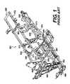
- FIG. 1illustrates such a frame 850 .
- the frame 850includes a spaced pair of upper tubular members 852 , 854 and a spaced pair of lower tubular members 856 , 858 .
- the upper and lower members 852 - 858are interconnected by respective spaced pairs of cross members 860 , 862 and 864 , 865 .
- Respective pairs of the upper and lower members 852 , 854 and 856 , 858are connected by laterally extending cross members 866 (connecting the upper members 852 , 854 ) and cross members 868 (connecting the lower members 856 , 858 ).
- a plate 870is connected between the lower members 856 , 858 to thereby add additional rigidity between the lower members 856 , 858 .
- these frameshave been either complex or have used a large amount of material, or both. It is possible to construct the frame with high strength metal alloys to increase strength properties of the frame without relatively increasing the weight. However, these metal alloys are costly and some require additional processing steps (such as post-weld heat treatment) in the manufacture of the frame.
- the frames described thereinwere designed for four-wheeled ATVs which typically use a McPherson suspension for the front wheels.
- This type of suspensioncan easily be accommodated by the described frames.
- straddle-type three-wheeled vehiclesare intrinsically less stable than four-wheeled vehicles (but it should be noted that the lower stability of a three-wheeled vehicle versus a four-wheeled vehicle should not be understood to mean that a three-wheeled vehicle is unstable to the point that it is dangerous to a user).
- the front wheels of a three-wheeled vehicleshould use a type of suspension that helps controlling the roll or sway of the vehicle more than a McPherson suspension.
- three-wheeled vehicles having two front wheels and one rear wheeldo not have as much room to accommodate components in the rear portion thereof as four-wheeled vehicles, such as ATVs, due to their reduced width at the back. Therefore, the vehicle components, such as the engine, air box, and fuel tank, cannot be arranged in the same manner. Thus, there is also a need for an arrangement of the vehicle components which is suitable for the space limitations of a straddle-type three-wheeled vehicle having two front wheels while maintaining accessibility to the components which require it.
- One aspect of the inventionprovides a frame suitable for use with a straddle-type three-wheeled vehicle having two front wheels.
- Another aspect of the inventionprovides a straddle-type three-wheeled vehicle for road use having a frame which is suitable for this type of application.
- the inventionprovides a straddle-type three-wheeled vehicle for road use having double A-arm front suspensions for the front wheels and a frame adapted to receive this type of suspension.
- Yet another aspect of the inventionprovides a three-wheeled vehicle having an arrangement of the vehicle components, such as the engine, air box, and fuel tank, on a frame of the vehicle.
- the inventionprovides a wheeled vehicle having a frame.
- the framehas an upper frame member, a lower frame member, a forward cross member interconnecting a forward portion of the upper frame member with a forward portion of the lower frame member, and a rearward cross member interconnecting a rearward portion of the upper frame member with a rearward portion of the lower frame member.
- the upper frame member, lower frame member, forward cross member, and rearward cross memberdefine a closed perimeter with a space therein.
- a strutextends from one of the upper frame member, the lower frame member, the forward cross member, and the rearward cross member, to another one of the upper frame member, the lower frame member, the forward cross member, and the rearward cross member.
- the upper frame member, lower frame member, forward cross member, rearward cross member, and strutare disposed along a longitudinal centerline of the vehicle.
- the vehiclealso has a straddle seat mounted on the upper frame member, a front left wheel, and a front right wheel.
- Each of the front wheelsis mounted to the frame via a front suspension.
- a single rear wheelis disposed along the longitudinal centerline of the vehicle.
- a swing armmounts the single rear wheel to the frame.
- a rear suspensionis operatively disposed between the swing arm and the frame.
- a steering columnis operatively connected to the front wheels to steer the front wheels.
- the steering columnextends inside the space rearwardly of the forward cross member.
- Handlebarsare connected to an upper end of the steering column above the upper frame member.
- An engineis disposed in the space and is operatively connected to the rear wheel to power the rear wheel.
- the strutextends diagonally from the forward cross member to the lower frame member.
- the terms “extends diagonally”refer to the orientation of a straight line which connects a first end of an element with the other end of the element. They do not require that the whole element which “extends diagonally” lie on such a line, although it is contemplated that it may do so.
- each of the front suspensionsis connected to the frame at a plurality of positions, one of the plurality of positions being on the strut.
- each of the front suspensionscomprises an upper A-arm and a lower A-arm.
- Each A-armhas a front arm and a rear arm. The rear arm of each upper A-arm is connected to the strut.
- the steering columnpasses through the upper frame member forwardly of the straddle seat.
- the steering columnpasses through the strut.
- the inventionprovides a frame for a wheeled vehicle.
- the framehas an upper frame member, a lower frame member, a forward cross member interconnecting a forward portion of the upper frame member with a forward portion of the lower frame member, and a rearward cross member interconnecting a rearward portion of the upper frame member with a rearward portion of the lower frame member.
- the upper frame member, lower frame member, forward cross member, and rearward cross memberdefine a closed perimeter with a space therein.
- a strutextends from one of the upper frame member, the lower frame member, the forward cross member, and the rearward cross member, to another one of the upper frame member, the lower frame member, the forward cross member, and the rearward cross member.
- a plurality of suspension attachment pointsare disposed on the frame.
- the upper frame member, lower frame member, forward cross member, rearward cross member, and strutare disposed along a common plane.
- the strutextends diagonally from the forward cross member to the lower frame member.
- the rearward cross memberextends rearwardly and upwardly from the lower frame member.
- the lower frame member and the rearward cross memberare integrally formed.
- the terms “integrally formed”mean that one element is formed as a unit with another element.
- the inventionprovides a wheeled vehicle having a frame.
- the framehas an upper frame member, a lower frame member, a forward cross member interconnecting a forward portion of the upper frame member with a forward portion of the lower frame member, and a rearward cross member interconnecting a rearward portion of the upper frame member with a rearward portion of the lower frame member.
- the upper frame member, lower frame member, forward cross member, and rearward cross memberare disposed along a longitudinal centerline of the vehicle and define a closed perimeter with a space therein.
- the vehiclealso has a straddle seat mounted on the upper frame member, a front left wheel, and a front right wheel. Each of the front wheels is mounted to the frame via a front suspension.
- a single rear wheelis disposed along the longitudinal centerline of the vehicle.
- a swing armmounts the single rear wheel to the frame.
- a rear suspensionis operatively disposed between the swing arm and the frame.
- a steering columnis operatively connected to the front wheels to steer the front wheels.
- the steering columnextends inside the space rearwardly of the forward cross member.
- Handlebarsare connected to an upper end of the steering column above the upper frame member.
- An engineis mounted in the space to the frame and is operatively connected to the rear wheel to power the rear wheel.
- An air boxis disposed in the space and has at least a portion thereof disposed above at least a portion of the engine and below the upper frame member.
- a fuel tankmounted in the space to below the upper frame member and rearwardly of the air box.
- a strutextends diagonally from the forward cross member to the lower frame member and a portion of the engine is mounted to the strut.
- the engineis a V-type engine.
- the enginehas a crankshaft disposed horizontally and perpendicularly to the longitudinal centerline of the vehicle, a front cylinder defining a front cylinder axis, and a rear cylinder defining a rear cylinder axis.
- the air boxis disposed longitudinally forwardly of the rear cylinder axis.
- the fuel tankhas a fuel tank filler cap disposed below the straddle seat.
- the straddle seatis mounted on the upper frame member such that the straddle seat is capable of being moved to a position providing access to the fuel tank filler cap.
- Embodiments of the present inventioneach have at least one of the above-mentioned aspects, but do not necessarily have all of them.
- FIG. 1is a perspective view of a prior art frame typically used in an ATV
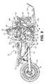
- FIG. 2is a perspective view, taken from a rear, left side, of a vehicle in accordance with the present invention
- FIG. 3is a top view of the vehicle of FIG. 2 ;
- FIG. 4is front view of the vehicle of FIG. 2 ;
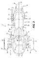
- FIG. 5is a back view of the vehicle of FIG. 2 ;
- FIG. 6is a left side elevation view of the vehicle of FIG. 2 ;
- FIG. 7is a right side elevation view of the vehicle of FIG. 2 ;
- FIG. 8is a left side elevation view of the internal components of the vehicle of FIG. 2 with some of the components removed for clarity;
- FIG. 9is a right side elevation view of the internal components of the vehicle of FIG. 2 with some of the components removed for clarity;
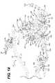
- FIG. 10is a top view of the internal components of the vehicle of FIG. 2 with some of the components removed for clarity;
- FIG. 11is a perspective view, taken from a rear, left side, of the internal components of the vehicle of FIG. 2 with some of the components removed for clarity;
- FIG. 12is a perspective view, taken from a rear, right side, of the internal components of the vehicle of FIG. 2 with some of the components removed for clarity;
- FIG. 13is a close-up perspective view, taken from a rear, left side, of the front portion of the frame and the front suspension of the vehicle of FIG. 2 ;
- FIG. 14is a close-up perspective view, taken from a rear, left side, of the front portion of the frame and the front suspension of the vehicle of FIG. 2 ;
- FIG. 15is a left side elevation view of an alternative embodiment of a frame in accordance with the present invention.
- FIG. 16is a left side elevation view of another alternative embodiment of a frame in accordance with the present invention.
- the vehicle 10has a straddle seat 12 located at least partially rearwardly of a center of the vehicle 10 and disposed along the longitudinal centerline 18 ( FIG. 2 ) thereof.
- the straddle seat 12has a first portion 20 for accommodating a driver, and a second portion 22 for accommodating a passenger behind the driver.
- the second portion 22is higher than the first portion 20 to permit the passenger to see in front of the vehicle 10 over the driver.
- a pair of handles 24are provided on either side of the second portion 22 for the passenger to hold onto.
- the straddle seat 12could be disposed at a different longitudinal location depending on the particular ergonomics of the vehicle 10 . It is also contemplated that the straddle seat 12 could only have the first portion 20 for the driver.
- a steering assemblyis disposed forwardly of the straddle seat 12 to allow a driver to steer the two front wheels 14 .
- the steering assemblyhas handlebars 26 connected to a steering column 28 ( FIG. 8 ).
- the steering column 28is connected to the two front wheels 14 via tie rods 27 , such that turning the handlebars 26 turns the steering column 28 which, through the tie rods 27 , turns the wheels 14 .
- the steering assemblycan optionally be provided with a power steering unit 29 ( FIG. 8 ) which facilitates steering of the vehicle 10 .
- the handlebars 26are provided with handles 30 for the driver to hold.
- the right handle 30can twist and acts as the throttle controller for the engine 32 ( FIG. 8 ).
- the throttlecould also be controlled by a separate lever disposed near one of the handles 30 .
- a brake actuatorin the form of a hand brake lever 34 , is provided near the right handle 30 for braking the vehicle 10 , as will be explained in greater detail below.
- the hand brake lever 34is provided generally forwardly of the right handle 30 so as to be actuated by multiple fingers of a user, however, it is contemplated that the hand brake lever 34 could be provided generally forwardly of the left handle 30 .
- a pair of driver foot pegs 36are provided on either sides of the vehicle 10 below the first portion 20 of the straddle seat 12 for a driver to rest his feet thereon.
- a pair of passenger foot pegs 38are provided on either side of the vehicle 10 below the second portion 22 of the straddle seat 12 for a passenger to rest his feet thereon.
- Another brake actuator, in the form of a foot brake lever 40is provided on a right side of the vehicle 10 below the first portion 20 of the straddle seat 12 for braking the vehicle 10 , as will be explained in greater detail below. As best seen in FIG.
- the foot brake lever 40is preferably provided near the right driver foot peg 36 such that the driver can actuate the foot brake lever 40 while a portion of his foot remains on the right driver foot peg 36 .
- the foot brake lever 40also preferably pivots about an axis which is coaxial with the right driver foot peg 36 in order to facilitate the actuation of the foot brake lever 40 by the driver.
- Each of the two front wheels 14is mounted to the frame 42 ( FIG. 8 ) of the vehicle 10 via a front suspension 44 as will be described in greater detail below.
- Each of the two front wheels 14has a tire 46 thereon which is suitable for road use.
- the tires 46are preferably inflated to a pressure between 138 kPa and 345 kPa.
- a fairing 48is disposed over each tire 46 to protect the driver from dirt and water which can be lifted by the tire 46 while it is rolling.
- Each of the two front wheels 14is also provided with a brake 50 .
- the brake 50is preferably a disc brake mounted onto a wheel hub of each wheel 14 , however other types of brakes are contemplated.
- the brakes 50each have a rotor 52 mounted onto the wheel hub and a stationary caliper 54 straddling the rotor 52 .
- the brake pads(not shown) are mounted to the caliper 54 so as to be disposed between the rotor 52 and the caliper 54 on either sides of the rotor 52 .
- By applying hydraulic pressure to a piston (not shown) inside the caliper 54the brake pads squeeze the rotor 52 which, through friction, brakes the wheel 14 .
- the rear wheel 16is mounted to the frame 42 via a swing arm 56 .
- the swing arm 56preferably has two arms pivotally mounted at a front thereof to the frame 42 and between which the rear wheel 16 is rotatably mounted at the rear of the two arms.
- a shock absorber unit 58is disposed between the swing arm 56 and the frame 42 , as will be discussed in greater detail below.
- the rear wheel 16has a tire 60 thereon which is suitable for road use.
- the tire 60is wider than the tires 46 . It is contemplated that the tire 60 could have a smaller width or the same width as the tires 46 . It is also contemplated that the rear wheel 16 could have two or more tires disposed next to each other thereon and still be considered a single rear wheel in the context of the present invention.
- the tire 60is preferably inflated to a pressure between 138 kPa and 345 kPa.
- a fairing 62is disposed over the tire 60 to protect the driver from dirt and water which can be lifted by the tire 60 while it is rolling.
- the rear wheel 16is provided with a brake 64 .
- the brake 64is preferably a disc brake mounted to a right side of wheel 16 .
- the brake 64has a rotor 66 , caliper 68 , brake pads (not shown), and a piston (not shown) similar to those used with brakes 50 .
- the brake 64brakes the rear wheel 16 in the same way as the brakes 50 brake the front wheels 14 .
- a wheel sprocket 70is mounted to a left side of the rear wheel 16 .
- a belt 72is disposed about the wheel sprocket 70 and a driving sprocket 71 to transmit power from the engine 32 to the rear wheel 16 .
- the driving sprocket 71receives power from the engine 32 via a transmission 73 .
- the transmission 73is operatively connected to the crankshaft 74 (schematically illustrated in FIG. 8 ) of the engine 32 . It is contemplated that a continuously variable transmission (CVT) could be provided between the crankshaft 74 and the driving sprocket 71 .
- CVTcontinuously variable transmission
- an exhaust pipe 76 extending on the right side of the vehicle 10 towards the rear thereofis attached to an exhaust port (not shown) of the engine 32 to improve engine performance and to reduce the noise level of the engine 32 .
- a vehicle body 78is attached to the frame 42 in order to protect the components mounted to the frame 42 and to make the vehicle 10 aesthetically pleasing. Components necessary to make vehicle 10 suitable for road use, such as lights 80 and a rear view mirror 82 , are mounted to the vehicle body 78 .
- the frame 42has an upper frame member 100 and a lower frame member 102 which are interconnected with each other, thus forming a closed perimeter with a space therein.
- a forward cross member 104interconnects a forward portion of the upper frame member 100 with a forward portion of the lower frame member 102 .
- a rearward cross member 106interconnects a rearward portion of the upper frame member 100 with a rearward portion of the lower frame member 102 .
- the upper frame member 100 , lower frame member 102 , forward cross member 104 , and rearward cross member 106are preferably made of metallic tubular beams having similarly sized rectangular cross-sections.
- the members 100 , 102 , 104 , 106could have different cross-sectional dimensions, could be made of non-metallic material (composite materials for example), and could also have a different configuration (I-beams or C-channels for example).
- the upper frame member 100is preferably bent in two locations such that a forward portion thereof is located higher than a rearward portion thereof.
- the forward portion of the frame 42provides sufficient vertical space to accommodate some of the vehicle components.
- the straddle seat 12which is mounted on the rearward portion of the upper frame member 100 , is maintained at a height from the ground which permits a driver of the vehicle 10 to rest his feet on the ground while sitting on the straddle seat 12 when the vehicle 10 is stopped.
- the upper frame member 100could have a different geometry.
- the upper frame member 100could be straight.
- the lower frame member 102 and the rearward cross member 106are preferably integrally formed as a single beam that is bent in one location. It is also contemplated that these members 102 , 106 could be welded to each other.
- the rearward cross member 106extends rearwardly and upwardly from the lower frame member 102 and is welded to the upper frame member 100 . The upper and lower ends of the forward cross member are welded to the upper frame member 100 and the lower frame member 102 respectively.
- the members 100 , 102 , 104 , 106may be joined by other means. For example, they may be joined by using brackets and fasteners. It is also contemplated that the members 100 , 102 , 104 , 106 could be made of a single beam which could be bent to obtain a closed perimeter.
- the frame 42also has a strut 108 which extends diagonally from the forward cross member 104 to the lower frame member 102 , to which it is preferably welded.
- a reinforcing member 109(as best seen in FIG. 13 ) is provided at the connection between the strut 108 and the lower frame member 102 to reinforce the connection.
- the strut 108also provides additional attachment points for some of the vehicle components, as will be discussed in greater detail below.
- the strut 108is preferably a C-channel, but could have different configurations.
- Two openings 110 , 112are provided on an upper surface of the strut 108 . These openings 110 , 112 reduce the weight of the strut 108 .
- the opening 110also allows the steering column 28 to pass therethrough.
- FIGS. 15 and 16illustrate alternative embodiments of the frame 42 .
- a L-shaped strut 208extends from the forward cross member 104 to the upper frame member 100 to reinforce the frame 42 .
- a straight strut 308extends diagonally from the upper frame member 100 to the lower frame member 102 to reinforce the frame 42 .
- the struts 208 and 308also provide additional attachment points for some of the vehicle components, as will be described below.
- Other shapes and locations of a strut for reinforcing the frame 42are also contemplated.
- the upper frame member 100 , lower frame member 102 , forward cross member 104 , rearward cross member 106 , and the strut 108are disposed on the longitudinal centerline 18 of the vehicle. Therefore, all of the members 100 , 102 , 104 , 106 of the frame 42 lie in a in a common vertical plane.
- a forward frame extension 114is connected to the front portion of the lower frame member 102 .
- the forward frame extension 114supports the front of the vehicle body 78 and a front storage bin (not shown).
- a tubular member 116is disposed on each side of the frame 42 to provide attachment points for the vehicle body 78 .
- Each tubular member 116is attached at a front end thereof to a connecting member 118 , which is itself connected to the forward cross member 104 .
- the back end of each tubular member 116is connected to an end portion of a fuel tank mounting bracket 120 , which is itself connected to the lower frame member 102 and the rearward cross member 106 via bracket 122 .
- each of the two front wheels 14is mounted to the frame 42 of the vehicle 10 via a front suspension 44 .
- Each of the front suspensions 44is a double A-arm suspension, also known as a double wishbone suspension.
- Each of the front suspensions 44has an upper A-arm 124 , a lower A-arm 126 , and a shock absorber unit 128 .
- the shock absorber unit 128preferably consists of a hydraulic shock absorber with a coil spring disposed around the shock absorber.
- One end of the upper A-arm 124 and of the lower A-arm 126is connected to a corresponding upper and lower end of a wheel spindle 130 of the wheel 14 .
- each A-arm 124 , 126is connected to suspension attachment points on the frame 42 as described below.
- the shock absorber unit 128is connected at one end to the lower A-arm 126 and to the forward cross member 104 via the connecting member 118 .
- Each A-arm 124 , 126has a front arm and a rear arm. As best seen in FIGS. 13 and 14 , both arms of the lower A-arms 126 are connected to the lower frame member 102 .
- the front arms of the upper A-arms 124are connected to the forward frame cross member 104 .
- the rear arms of the upper A-arms 124are connected to the strut 108 . In the embodiments shown in FIGS.
- the rear arms of the upper A-armsare connected to the struts 208 ( FIG. 15) and 308 ( FIG. 16 ), as the case may be.
- This type of front suspension 44provides a good control on the roll or sway of the vehicle 10 .
- Each wheel 14has a pivot axis defined by a generally vertical line passing through the ends of the upper and lower A-arms 124 , 126 to which the wheel spindle 130 is connected.
- the pivot axis of each wheel 14is preferably located rearwardly of the front of the lower frame member 102 .
- the rear wheel 16is mounted to the frame 42 via a swing arm 56 . More specifically, the swing arm 56 is pivotally mounted to a bushing 132 ( FIG. 14 ) in bracket 122 .
- the length of the swing arm 56is preferably selected such that at least a portion of the rear wheel 16 is disposed below the rear portion of the upper frame member 100 .
- the shock absorber unit 58is preferably mounted to the swing arm 56 at one end and to the rearward cross member 106 at the other, so as to be disposed along the longitudinal centerline 18 of the vehicle 10 .
- the shock absorber unit 58preferably consists of a hydraulic shock absorber with a coil spring disposed around the shock absorber.
- the engine 32 and many of its componentsare disposed inside the space formed by the closed perimeter of the frame 42 .
- the engine 32is mounted at the front thereof to the strut 108 via strut brackets 134 ( FIGS. 13 , 14 ).
- the engine 32is also mounted at the rear thereof to two bushings 136 ( FIGS. 13 , 14 ) on bracket 122 (which, as previously mentioned, is mounted on the rearward cross member 106 ) via engine mount bracket 138 .
- An elastomeric material, such as rubber,is preferably disposed between the engine 32 and its attachment points 134 , 136 so as to reduce the transmission of vibrations from the engine 32 to the frame 42 .
- the crankshaft 74 of the engine 32is disposed horizontally and perpendicularly to the longitudinal center line 18 of the vehicle 10 .
- the engine 32is preferably mounted to the frame 42 so that it does not sit on the lower frame member 102 also to reduce the transmission of vibrations from the engine 32 to the frame 42 .
- the engine 32is a V-type engine having a front cylinder 140 and a rear cylinder 142 .
- the engine 32is also know as a V-twin engine.
- the front cylinder 140defines a front cylinder axis 144 passing through a center thereof.
- the rear cylinder 142defines a rear cylinder axis 146 passing through a center thereof.
- the steering column 28passes through the upper frame member 100 forwardly of the straddle seat 12 and extends inside the space formed by the closed perimeter of the frame 42 . It is contemplated that the steering column 28 could pass to one side of the upper frame member 100 instead of passing through it.
- the steering column 28is disposed rearwardly of the forward cross member 104 and in front of the engine 32 . As best seen in FIGS. 13 and 14 , the steering column 28 has a bent portion 148 so as to not interfere with the front cylinder 140 .
- the steering column 28passes through the strut 108 .
- the lower end of the steering column 28is connected to the power steering unit 29 below the strut 108 .
- the power steering unit 29is connected to the forward cross member 104 .
- the lower end of the steering column 28could be pivotally connected directly to the forward cross member 104 in cases where a power steering unit 29 is not being used.
- An air box 150is provided in fluid communication with an inlet port (not shown) of each cylinder 140 , 142 to enhance engine performance, prevent water and dirt from entering the engine 32 , and reduce the noise coming out of the inlet ports.
- the air box 150has an inlet in the form of two tubes 152 having an open end pointing towards a front of the vehicle 10 .
- a portion of the air box 150is disposed above the engine 32 forwardly of the rear cylinder axis 146 .
- a portion of the air box 150is disposed between the two cylinder axes 144 , 146 .
- the air box 150is mounted to and supported by the throttle body (not shown) which is disposed between the cylinders 140 , 142 .
- the air box 150is preferably attached to the throttle body with one or more threaded fasteners.
- a rubber support(not shown) is disposed between the engine 32 and the air box 150 to provide additional support to the air box 150 .
- the airflows in the tubes 152 , enters the air box 150 , passes inside the throttle body which is used to regulate the flow of air, and enters the cylinders 140 , 142 to be combusted therein.
- the fuel tank 154 of the vehicle 10is mounted inside the space formed by the closed perimeter of the frame 42 rearwardly of the engine 32 and the air box 150 .
- the fuel tank 154is attached to the upper frame member 100 and to the fuel tank mounting bracket 120 .
- the fuel tankis positioned below the upper frame member 100 , below the straddle seat 12 , such that the fuel tank filler cap 156 can be accessed under the straddle seat 12 to permit refilling of the fuel tank 154 .
- the straddle seat 12is preferably hinged to the vehicle 10 so as to pivot to a position providing access to the fuel tank filler cap 156 .
- the straddle seat 12could be removable.
- a side bracket 158is provided on each side of the lower frame member 102 to mount additional components of the vehicle 10 .
- an oil cooler 160 and an oil tank 162are mounted to the left side bracket 158 .
- an engine radiator 164having a fan 166 mounted thereon, is mounted to the right side bracket 158 . Locating the radiator 164 and the oil cooler 160 on either side of the frame 42 places them in the airflow created by the vehicle 10 when it is moving, thus enhancing the cooling provided by these components.
- a plate 168is preferably provided on each lower A-arm 126 to direct additional air towards the radiator 164 and the oil cooler 160 .
- An electronic brake control unit 170is mounted to the lower frame member 102 .
- the engine coolant reservoir 172( FIG. 12 ) is mounted to the forward cross member 104 via the right connecting member 118 .
- An electronic control unit (ECU), battery, sensors, (all not shown) and other components necessary to the operation of the vehicle 10are also mounted to the frame 42 .
Landscapes
- Engineering & Computer Science (AREA)
- Mechanical Engineering (AREA)
- Automatic Cycles, And Cycles In General (AREA)
- Body Structure For Vehicles (AREA)
Abstract
Description
Claims (25)
Priority Applications (2)
| Application Number | Priority Date | Filing Date | Title |
|---|---|---|---|
| US11/381,036US7543672B2 (en) | 2006-05-01 | 2006-05-01 | Straddle-type wheeled vehicle and frame thereof |
| US12/464,485US7806215B2 (en) | 2006-05-01 | 2009-05-12 | Straddle-type wheeled vehicle and frame thereof |
Applications Claiming Priority (1)
| Application Number | Priority Date | Filing Date | Title |
|---|---|---|---|
| US11/381,036US7543672B2 (en) | 2006-05-01 | 2006-05-01 | Straddle-type wheeled vehicle and frame thereof |
Related Child Applications (1)
| Application Number | Title | Priority Date | Filing Date |
|---|---|---|---|
| US12/464,485DivisionUS7806215B2 (en) | 2006-05-01 | 2009-05-12 | Straddle-type wheeled vehicle and frame thereof |
Publications (2)
| Publication Number | Publication Date |
|---|---|
| US20070251745A1 US20070251745A1 (en) | 2007-11-01 |
| US7543672B2true US7543672B2 (en) | 2009-06-09 |
Family
ID=38647278
Family Applications (2)
| Application Number | Title | Priority Date | Filing Date |
|---|---|---|---|
| US11/381,036Active2027-10-05US7543672B2 (en) | 2006-05-01 | 2006-05-01 | Straddle-type wheeled vehicle and frame thereof |
| US12/464,485ActiveUS7806215B2 (en) | 2006-05-01 | 2009-05-12 | Straddle-type wheeled vehicle and frame thereof |
Family Applications After (1)
| Application Number | Title | Priority Date | Filing Date |
|---|---|---|---|
| US12/464,485ActiveUS7806215B2 (en) | 2006-05-01 | 2009-05-12 | Straddle-type wheeled vehicle and frame thereof |
Country Status (1)
| Country | Link |
|---|---|
| US (2) | US7543672B2 (en) |
Cited By (26)
| Publication number | Priority date | Publication date | Assignee | Title |
|---|---|---|---|---|
| US20100044134A1 (en)* | 2008-08-22 | 2010-02-25 | James Kevin Feutz | Snowmobile conversion kit |
| US20100078254A1 (en)* | 2008-09-29 | 2010-04-01 | Bernard Frank Rolfe | Body for pneumatic vehicle |
| US20100078253A1 (en)* | 2008-09-29 | 2010-04-01 | Bernard Frank Rolfe | Pneumatic powertrain for an automotive vehicle |
| US20100078245A1 (en)* | 2008-09-29 | 2010-04-01 | Bernard Frank Rolfe | Chassis for pneumatic vehicle |
| US20100230192A1 (en)* | 2009-03-12 | 2010-09-16 | Riley Robert Q | Hybrid vehicle |
| USD678124S1 (en) | 2011-10-31 | 2013-03-19 | Tanom Motors, LLC | Reverse trike |
| USD682158S1 (en) | 2011-10-31 | 2013-05-14 | Tanom Motors, LLC | Reverse trike |
| US8517423B1 (en)* | 2012-03-20 | 2013-08-27 | Club Car, Llc | Modular frame structure for off road vehicle |
| USD689794S1 (en) | 2011-03-21 | 2013-09-17 | Polaris Industries Inc. | Three wheeled vehicle |
| US8540045B2 (en) | 2011-10-31 | 2013-09-24 | Tanom Motors, LLC | Systems and apparatus for a three-wheeled vehicle |
| US8544587B2 (en) | 2011-03-21 | 2013-10-01 | Polaris Industries Inc. | Three wheeled vehicle |
| WO2015036984A1 (en)* | 2013-09-13 | 2015-03-19 | Bombardier Recreational Products Inc. | Storage bin and radiator assembly for a vehicle |
| US9188198B2 (en) | 2013-10-28 | 2015-11-17 | Tanom Motors, LLC | Drive train and systems for a three-wheeled vehicle |
| US9604683B2 (en) | 2015-06-28 | 2017-03-28 | Gregory W Kunsch | Rear engine, front wheel drive three wheeled vehicle |
| US9636995B2 (en) | 2013-09-13 | 2017-05-02 | Bombardier Recreational Products Inc. | Radiator assembly for a vehicle |
| US9802646B1 (en) | 2013-11-08 | 2017-10-31 | Hydro-Gear Limited Partnership | Vehicle with steering mechanism |
| US10787205B2 (en) | 2016-01-22 | 2020-09-29 | Bombardier Recreational Products Inc. | Fender for a wheeled vehicle |
| US10843758B2 (en) | 2016-01-29 | 2020-11-24 | Bombardier Recreational Products Inc. | Vehicle having a suspension assembly including a swing arm |
| US10906602B2 (en) | 2016-01-29 | 2021-02-02 | Bombardier Recreational Products Inc. | Family of three-wheeled straddle-seat vehicles |
| US11034409B2 (en) | 2017-07-31 | 2021-06-15 | Bombardier Recreational Products Inc. | Suspension assembly for a vehicle |
| US11130539B2 (en) | 2017-05-12 | 2021-09-28 | Bombardier Recreational Products Inc. | Vehicle with upper and lower frame portions |
| USD1032429S1 (en) | 2021-12-06 | 2024-06-25 | Polaris Industries Inc. | Vehicle bonnet |
| US12187381B2 (en) | 2022-02-15 | 2025-01-07 | Arctic Cat Inc. | Snowmobile frame |
| USD1063697S1 (en) | 2023-03-07 | 2025-02-25 | Arctic Cat Inc. | Rear kick-up for a snow vehicle |
| USD1082637S1 (en) | 2023-03-07 | 2025-07-08 | Arctic Cat Inc. | Running board for a snow vehicle |
| US12434783B2 (en) | 2022-02-16 | 2025-10-07 | Arctic Cat Inc. | Fuel tank and seat assembly for a vehicle |
Families Citing this family (17)
| Publication number | Priority date | Publication date | Assignee | Title |
|---|---|---|---|---|
| US7543673B2 (en)* | 2006-07-14 | 2009-06-09 | Bombardier Recreational Products Inc. | Wheeled vehicle with water deflectors |
| WO2008115461A2 (en)* | 2007-03-16 | 2008-09-25 | Polaris Industries Inc. | Vehicle |
| US20090205894A1 (en)* | 2008-02-19 | 2009-08-20 | Eaton Harry E | Leaning vehicle |
| US7926607B2 (en)* | 2008-03-05 | 2011-04-19 | Paul Seiter | Three-wheel vehicle |
| US8408348B2 (en)* | 2008-08-29 | 2013-04-02 | Suzuki Motor Corporation | Snowmobile and engine for snowmobile |
| JP2011143857A (en)* | 2010-01-15 | 2011-07-28 | Honda Motor Co Ltd | Vehicle |
| US20110272906A1 (en)* | 2010-05-05 | 2011-11-10 | Hall David R | Swingarm Suspension |
| US9050869B1 (en) | 2010-06-29 | 2015-06-09 | Derrick Pelzer | Torque reversing suspension system |
| CA2840176A1 (en)* | 2011-06-28 | 2013-01-03 | Bombardier Recreational Products Inc. | Vehicle foot board and pedal assembly |
| WO2013165359A1 (en)* | 2012-04-30 | 2013-11-07 | Bombardier Recreational Products Inc. | Air ventilation systems for vehicles |
| US9387902B2 (en)* | 2014-01-16 | 2016-07-12 | Scorpion Trikes, Inc. | Assembly for increasing motorcycle wheel count |
| JP5952516B1 (en)* | 2014-09-29 | 2016-07-13 | ヤマハ発動機株式会社 | vehicle |
| US9738220B2 (en)* | 2015-08-28 | 2017-08-22 | Faraday & Future, Inc. | Steering wheel having integrated horn actuator and the method of operating the same |
| JP6122921B2 (en) | 2015-08-31 | 2017-04-26 | 本田技研工業株式会社 | Saddle riding type vehicle |
| US10618404B2 (en) | 2016-01-29 | 2020-04-14 | Bombardier Recreational Products Inc. | Vehicle having dual air intake systems |
| RU169393U1 (en)* | 2016-05-11 | 2017-03-16 | Федеральное государственное бюджетное образовательное учреждение высшего образования "Тихоокеанский государственный университет" | Powertrain of a three-wheeled all-terrain vehicle |
| JP7122227B2 (en) | 2018-11-02 | 2022-08-19 | カワサキモータース株式会社 | straddle-type vehicle |
Citations (20)
| Publication number | Priority date | Publication date | Assignee | Title |
|---|---|---|---|---|
| US3521904A (en) | 1968-03-20 | 1970-07-28 | Lawrence E Sheffer | Vehicle structure |
| US3698502A (en) | 1968-02-22 | 1972-10-17 | Pierre C Patin | Stabilized three-wheel vehicle |
| US4623167A (en)* | 1983-09-13 | 1986-11-18 | Honda Giken Kogyo Kabushiki Kaisha | Vehicle frame construction for buggies with riding saddles |
| US4735275A (en)* | 1985-10-07 | 1988-04-05 | Honda Giken Kogyo Kabushiki Kaisha | Body frame for vehicles |
| US4770262A (en) | 1984-08-31 | 1988-09-13 | Honda Giken Kogyo Kabushiki Kaisha | Four-wheel motor vehicle with riding saddle seat |
| US4924961A (en) | 1987-07-10 | 1990-05-15 | Bcs S.P.A. | Vehicle for gardening and agricultural work |
| US5480001A (en) | 1993-10-19 | 1996-01-02 | Honda Giken Kogyo Kabushiki Kaisha | Frame structure for a motorcycle |
| US5845728A (en) | 1995-09-29 | 1998-12-08 | Honda Giken Kogyo Kabushiki Kaisha | Body frame for motorcycle |
| US5845918A (en) | 1996-10-29 | 1998-12-08 | Grinde; James E. | All terrain vehicle with semi-independent rear suspension |
| US5975624A (en) | 1996-04-03 | 1999-11-02 | Polaris Industries Inc. | All terrain vehicle frame |
| US6142498A (en) | 1998-12-11 | 2000-11-07 | Chrome Specialties, Inc. | Motorcycle frame |
| US6170841B1 (en) | 1997-11-26 | 2001-01-09 | Kawasaki Jukogyo Kabushiki Kaisha | Steering system for straddle type four-wheeled all-terrain vehicle |
| US6305700B1 (en) | 1997-12-17 | 2001-10-23 | Daimlerchrysler Ag | Independent suspension with a steering knuckle supported by a coupling rod |
| EP0826584B1 (en) | 1996-08-30 | 2003-04-23 | Honda Giken Kogyo Kabushiki Kaisha | Body frame structure of motorcycle |
| US6572129B1 (en)* | 2000-07-24 | 2003-06-03 | Gregory Bean | Dual power recumbent tricycle |
| WO2003070548A1 (en) | 2002-02-22 | 2003-08-28 | Bombardier Recreational Products Inc. | Components for a three-wheeled vehicle to permit leaning of the driver |
| US20040050605A1 (en)* | 2002-02-22 | 2004-03-18 | Berthold Fecteau | Three-wheel vehicle and concentric intermediate sprocket assembly therefor |
| US6799781B2 (en)* | 2000-03-13 | 2004-10-05 | Bombardier Recreational Products Inc. | Frames for all-terrain vehicles |
| US20060006623A1 (en) | 2004-07-09 | 2006-01-12 | Bombardier Recreational Products Inc. | Front drive geometry for an all-terrain vehicle |
| US7021664B2 (en) | 2002-10-18 | 2006-04-04 | Bombardier Recreational Products Inc. | Fuel tank for an all-terrain vehicle |
Family Cites Families (4)
| Publication number | Priority date | Publication date | Assignee | Title |
|---|---|---|---|---|
| JP3517217B2 (en)* | 2001-01-31 | 2004-04-12 | 川崎重工業株式会社 | Breather system for riding type four-wheel rough terrain vehicle |
| EP1476679A1 (en)* | 2002-02-22 | 2004-11-17 | Bombardier Recreational Products Inc. | Three-wheeled vehicle with a continuously variable transmission |
| US20040035623A1 (en)* | 2002-02-22 | 2004-02-26 | Berthold Fecteau | Frame configuration for a three-wheel vehicle |
| US20040140140A1 (en)* | 2003-01-17 | 2004-07-22 | Etienne Guay | Three-wheeled vehicle having an oil cooler assembly |
- 2006
- 2006-05-01USUS11/381,036patent/US7543672B2/enactiveActive
- 2009
- 2009-05-12USUS12/464,485patent/US7806215B2/enactiveActive
Patent Citations (21)
| Publication number | Priority date | Publication date | Assignee | Title |
|---|---|---|---|---|
| US3698502A (en) | 1968-02-22 | 1972-10-17 | Pierre C Patin | Stabilized three-wheel vehicle |
| US3521904A (en) | 1968-03-20 | 1970-07-28 | Lawrence E Sheffer | Vehicle structure |
| US4623167A (en)* | 1983-09-13 | 1986-11-18 | Honda Giken Kogyo Kabushiki Kaisha | Vehicle frame construction for buggies with riding saddles |
| US4770262A (en) | 1984-08-31 | 1988-09-13 | Honda Giken Kogyo Kabushiki Kaisha | Four-wheel motor vehicle with riding saddle seat |
| US4735275A (en)* | 1985-10-07 | 1988-04-05 | Honda Giken Kogyo Kabushiki Kaisha | Body frame for vehicles |
| US4924961A (en) | 1987-07-10 | 1990-05-15 | Bcs S.P.A. | Vehicle for gardening and agricultural work |
| US5480001A (en) | 1993-10-19 | 1996-01-02 | Honda Giken Kogyo Kabushiki Kaisha | Frame structure for a motorcycle |
| US5845728A (en) | 1995-09-29 | 1998-12-08 | Honda Giken Kogyo Kabushiki Kaisha | Body frame for motorcycle |
| US5975624A (en) | 1996-04-03 | 1999-11-02 | Polaris Industries Inc. | All terrain vehicle frame |
| EP0826584B1 (en) | 1996-08-30 | 2003-04-23 | Honda Giken Kogyo Kabushiki Kaisha | Body frame structure of motorcycle |
| US5845918A (en) | 1996-10-29 | 1998-12-08 | Grinde; James E. | All terrain vehicle with semi-independent rear suspension |
| US6170841B1 (en) | 1997-11-26 | 2001-01-09 | Kawasaki Jukogyo Kabushiki Kaisha | Steering system for straddle type four-wheeled all-terrain vehicle |
| US6305700B1 (en) | 1997-12-17 | 2001-10-23 | Daimlerchrysler Ag | Independent suspension with a steering knuckle supported by a coupling rod |
| US6142498A (en) | 1998-12-11 | 2000-11-07 | Chrome Specialties, Inc. | Motorcycle frame |
| US6799781B2 (en)* | 2000-03-13 | 2004-10-05 | Bombardier Recreational Products Inc. | Frames for all-terrain vehicles |
| US6572129B1 (en)* | 2000-07-24 | 2003-06-03 | Gregory Bean | Dual power recumbent tricycle |
| WO2003070548A1 (en) | 2002-02-22 | 2003-08-28 | Bombardier Recreational Products Inc. | Components for a three-wheeled vehicle to permit leaning of the driver |
| US20040050605A1 (en)* | 2002-02-22 | 2004-03-18 | Berthold Fecteau | Three-wheel vehicle and concentric intermediate sprocket assembly therefor |
| US6948581B2 (en) | 2002-02-22 | 2005-09-27 | Bombardier Recreational Products Inc | Three-wheel vehicle and concentric intermediate sprocket assembly therefor |
| US7021664B2 (en) | 2002-10-18 | 2006-04-04 | Bombardier Recreational Products Inc. | Fuel tank for an all-terrain vehicle |
| US20060006623A1 (en) | 2004-07-09 | 2006-01-12 | Bombardier Recreational Products Inc. | Front drive geometry for an all-terrain vehicle |
Non-Patent Citations (3)
| Title |
|---|
| International Search Report, PCT/US2006/016352; Mailed Jan. 31, 2007; Feber, Laurent. |
| Reinmech Sales Brochure Located, May 25, 2000. |
| Suzuki LT-F160 Parts Catalog, May 1997. |
Cited By (43)
| Publication number | Priority date | Publication date | Assignee | Title |
|---|---|---|---|---|
| US20100044134A1 (en)* | 2008-08-22 | 2010-02-25 | James Kevin Feutz | Snowmobile conversion kit |
| US7891455B2 (en)* | 2008-08-22 | 2011-02-22 | James Kevin Feutz | Snowmobile conversion kit |
| US20100078254A1 (en)* | 2008-09-29 | 2010-04-01 | Bernard Frank Rolfe | Body for pneumatic vehicle |
| US20100078253A1 (en)* | 2008-09-29 | 2010-04-01 | Bernard Frank Rolfe | Pneumatic powertrain for an automotive vehicle |
| US20100078245A1 (en)* | 2008-09-29 | 2010-04-01 | Bernard Frank Rolfe | Chassis for pneumatic vehicle |
| US9227507B2 (en) | 2008-09-29 | 2016-01-05 | Deakin University | Pneumatic powertrain for an automotive vehicle |
| US8313121B2 (en)* | 2008-09-29 | 2012-11-20 | Deakin University | Chassis for pneumatic vehicle |
| US8317257B2 (en) | 2008-09-29 | 2012-11-27 | Deakin University | Body for pneumatic vehicle |
| US8342283B2 (en) | 2008-09-29 | 2013-01-01 | Deakin University | Pneumatic powertrain for an automotive vehicle |
| US20100230192A1 (en)* | 2009-03-12 | 2010-09-16 | Riley Robert Q | Hybrid vehicle |
| US11572118B2 (en) | 2011-03-21 | 2023-02-07 | Polaris Industries Inc. | Three-wheeled vehicle |
| US10300971B2 (en) | 2011-03-21 | 2019-05-28 | Polaris Industries Inc. | Three-wheeled vehicle |
| USD689794S1 (en) | 2011-03-21 | 2013-09-17 | Polaris Industries Inc. | Three wheeled vehicle |
| US8695746B2 (en) | 2011-03-21 | 2014-04-15 | Polaris Industries Inc. | Three wheeled vehicle |
| US8544587B2 (en) | 2011-03-21 | 2013-10-01 | Polaris Industries Inc. | Three wheeled vehicle |
| US9004214B2 (en) | 2011-03-21 | 2015-04-14 | Polaris Industries Inc. | Three wheeled vehicle |
| USD682158S1 (en) | 2011-10-31 | 2013-05-14 | Tanom Motors, LLC | Reverse trike |
| USD761692S1 (en) | 2011-10-31 | 2016-07-19 | Tanom Motors, LLC | Storage compartment for a vehicle |
| US8887853B2 (en) | 2011-10-31 | 2014-11-18 | Tanom Motors, LLC | Systems and apparatus for a three-wheeled vehicle |
| USD678124S1 (en) | 2011-10-31 | 2013-03-19 | Tanom Motors, LLC | Reverse trike |
| USD710274S1 (en) | 2011-10-31 | 2014-08-05 | Tanom Motors, LLC | Windshield configuration for reverse trike |
| US9650099B2 (en) | 2011-10-31 | 2017-05-16 | Tanom Motors, LLC | Systems and apparatus for a three-wheeled vehicle |
| US8540045B2 (en) | 2011-10-31 | 2013-09-24 | Tanom Motors, LLC | Systems and apparatus for a three-wheeled vehicle |
| US8517423B1 (en)* | 2012-03-20 | 2013-08-27 | Club Car, Llc | Modular frame structure for off road vehicle |
| US8690189B2 (en)* | 2012-03-20 | 2014-04-08 | Club Car, Llc | Modular frame structure for off road vehicle |
| US9636995B2 (en) | 2013-09-13 | 2017-05-02 | Bombardier Recreational Products Inc. | Radiator assembly for a vehicle |
| US9694872B2 (en) | 2013-09-13 | 2017-07-04 | Bombardier Recreational Products Inc. | Storage bin and radiator assembly for a vehicle |
| WO2015036984A1 (en)* | 2013-09-13 | 2015-03-19 | Bombardier Recreational Products Inc. | Storage bin and radiator assembly for a vehicle |
| US9188198B2 (en) | 2013-10-28 | 2015-11-17 | Tanom Motors, LLC | Drive train and systems for a three-wheeled vehicle |
| US9802646B1 (en) | 2013-11-08 | 2017-10-31 | Hydro-Gear Limited Partnership | Vehicle with steering mechanism |
| US9604683B2 (en) | 2015-06-28 | 2017-03-28 | Gregory W Kunsch | Rear engine, front wheel drive three wheeled vehicle |
| US10787205B2 (en) | 2016-01-22 | 2020-09-29 | Bombardier Recreational Products Inc. | Fender for a wheeled vehicle |
| US10906602B2 (en) | 2016-01-29 | 2021-02-02 | Bombardier Recreational Products Inc. | Family of three-wheeled straddle-seat vehicles |
| US10875595B2 (en) | 2016-01-29 | 2020-12-29 | Bombardier Recreational Products Inc. | Three-wheeled straddle-seat vehicle |
| US10843758B2 (en) | 2016-01-29 | 2020-11-24 | Bombardier Recreational Products Inc. | Vehicle having a suspension assembly including a swing arm |
| US11130539B2 (en) | 2017-05-12 | 2021-09-28 | Bombardier Recreational Products Inc. | Vehicle with upper and lower frame portions |
| US11034409B2 (en) | 2017-07-31 | 2021-06-15 | Bombardier Recreational Products Inc. | Suspension assembly for a vehicle |
| USD1032429S1 (en) | 2021-12-06 | 2024-06-25 | Polaris Industries Inc. | Vehicle bonnet |
| US12187381B2 (en) | 2022-02-15 | 2025-01-07 | Arctic Cat Inc. | Snowmobile frame |
| US12208854B2 (en) | 2022-02-15 | 2025-01-28 | Arctic Cat Inc. | Snowmobile frame |
| US12434783B2 (en) | 2022-02-16 | 2025-10-07 | Arctic Cat Inc. | Fuel tank and seat assembly for a vehicle |
| USD1063697S1 (en) | 2023-03-07 | 2025-02-25 | Arctic Cat Inc. | Rear kick-up for a snow vehicle |
| USD1082637S1 (en) | 2023-03-07 | 2025-07-08 | Arctic Cat Inc. | Running board for a snow vehicle |
Also Published As
| Publication number | Publication date |
|---|---|
| US7806215B2 (en) | 2010-10-05 |
| US20090218153A1 (en) | 2009-09-03 |
| US20070251745A1 (en) | 2007-11-01 |
Similar Documents
| Publication | Publication Date | Title |
|---|---|---|
| US7543672B2 (en) | Straddle-type wheeled vehicle and frame thereof | |
| US20250187693A1 (en) | Two-wheeled vehicle | |
| US10843758B2 (en) | Vehicle having a suspension assembly including a swing arm | |
| EP2196384B1 (en) | Straddle-type wheeled vehicle and frame thereof | |
| US10442264B2 (en) | Vehicle suspension assembly | |
| US20040035623A1 (en) | Frame configuration for a three-wheel vehicle | |
| US7954835B2 (en) | Front wheel suspension structure for saddle-type vehicle, and vehicle incorporating same | |
| US20080277184A1 (en) | Frame for an all-terrain vehicle | |
| CN110997360B (en) | Suspension Components for Vehicles | |
| CN102056788A (en) | Power steering for an all terrain vehicle | |
| JP4865914B2 (en) | vehicle | |
| CN102039968B (en) | Bestriding wheel-type tricycle and frame thereof | |
| US6581716B1 (en) | All terrain vehicle with rear-facing rear arm bracket | |
| US20180215220A1 (en) | Knuckle for a vehicle suspension assembly | |
| JP2010516545A5 (en) | ||
| CN108698664A (en) | Three-wheel straddle seat vehicle | |
| US11130539B2 (en) | Vehicle with upper and lower frame portions | |
| CN115349049B (en) | Support structure for evaporative emission control device | |
| CA2587764A1 (en) | Frame for an all-terrain vehicle |
Legal Events
| Date | Code | Title | Description |
|---|---|---|---|
| AS | Assignment | Owner name:BOMBARDIER RECREATIONAL PRODUCTS INC, CANADA Free format text:ASSIGNMENT OF ASSIGNORS INTEREST;ASSIGNORS:CODERE, BRUCE;MASTINE, BRIAN;REEL/FRAME:019013/0992 Effective date:20060503 | |
| FEPP | Fee payment procedure | Free format text:PAYOR NUMBER ASSIGNED (ORIGINAL EVENT CODE: ASPN); ENTITY STATUS OF PATENT OWNER: LARGE ENTITY | |
| STCF | Information on status: patent grant | Free format text:PATENTED CASE | |
| CC | Certificate of correction | ||
| FPAY | Fee payment | Year of fee payment:4 | |
| AS | Assignment | Owner name:BANK OF MONTREAL, CANADA Free format text:SECURITY AGREEMENT;ASSIGNOR:BOMBARDIER RECREATIONAL PRODUCTS INC.;REEL/FRAME:031159/0540 Effective date:20130822 | |
| AS | Assignment | Owner name:BANK OF MONTREAL, CANADA Free format text:SECURITY AGREEMENT;ASSIGNOR:BOMBARDIER RECREATIONAL PRODUCTS INC.;REEL/FRAME:031156/0144 Effective date:20130822 | |
| FPAY | Fee payment | Year of fee payment:8 | |
| AS | Assignment | Owner name:BANK OF MONTREAL, AS ADMINISTRATIVE AGENT, CANADA Free format text:SECURITY AGREEMENT (REVOLVER);ASSIGNOR:BOMBARDIER RECREATIONAL PRODUCTS INC.;REEL/FRAME:047221/0038 Effective date:20180929 | |
| AS | Assignment | Owner name:BANK OF MONTREAL, AS ADMINISTRATIVE AGENT, CANADA Free format text:SECURITY AGREEMENT (TERM LOAN);ASSIGNOR:BOMBARDIER RECREATIONAL PRODUCTS INC.;REEL/FRAME:047237/0098 Effective date:20180929 | |
| MAFP | Maintenance fee payment | Free format text:PAYMENT OF MAINTENANCE FEE, 12TH YEAR, LARGE ENTITY (ORIGINAL EVENT CODE: M1553); ENTITY STATUS OF PATENT OWNER: LARGE ENTITY Year of fee payment:12 |