US7542815B1 - Extraction of left/center/right information from two-channel stereo sources - Google Patents
Extraction of left/center/right information from two-channel stereo sourcesDownload PDFInfo
- Publication number
- US7542815B1 US7542815B1US10/932,214US93221404AUS7542815B1US 7542815 B1US7542815 B1US 7542815B1US 93221404 AUS93221404 AUS 93221404AUS 7542815 B1US7542815 B1US 7542815B1
- Authority
- US
- United States
- Prior art keywords
- vector
- derived
- input
- center
- vectors
- Prior art date
- Legal status (The legal status is an assumption and is not a legal conclusion. Google has not performed a legal analysis and makes no representation as to the accuracy of the status listed.)
- Active, expires
Links
- 238000000605extractionMethods0.000titledescription3
- 239000013598vectorSubstances0.000claimsabstractdescription394
- 238000000034methodMethods0.000claimsabstractdescription31
- 238000012545processingMethods0.000claimsabstractdescription26
- 230000005236sound signalEffects0.000claimsabstractdescription7
- 230000015654memoryEffects0.000claimsdescription11
- 230000008569processEffects0.000claimsdescription6
- 238000003672processing methodMethods0.000claims1
- 238000000354decomposition reactionMethods0.000description12
- 230000006870functionEffects0.000description5
- 230000002596correlated effectEffects0.000description4
- 238000001914filtrationMethods0.000description4
- 239000000463materialSubstances0.000description4
- 230000005540biological transmissionEffects0.000description3
- 230000000694effectsEffects0.000description3
- 230000008901benefitEffects0.000description2
- 230000000875corresponding effectEffects0.000description2
- 238000010586diagramMethods0.000description2
- 239000011159matrix materialSubstances0.000description2
- 238000012986modificationMethods0.000description2
- 230000004048modificationEffects0.000description2
- 230000035807sensationEffects0.000description2
- 230000003247decreasing effectEffects0.000description1
- 230000001419dependent effectEffects0.000description1
- 230000003287optical effectEffects0.000description1
- 238000012805post-processingMethods0.000description1
- 238000007781pre-processingMethods0.000description1
- 230000009467reductionEffects0.000description1
- 238000005070samplingMethods0.000description1
- 238000010561standard procedureMethods0.000description1
- 238000012360testing methodMethods0.000description1
- 230000001052transient effectEffects0.000description1
Images


Classifications
- H—ELECTRICITY
- H04—ELECTRIC COMMUNICATION TECHNIQUE
- H04S—STEREOPHONIC SYSTEMS
- H04S5/00—Pseudo-stereo systems, e.g. in which additional channel signals are derived from monophonic signals by means of phase shifting, time delay or reverberation
- H04S5/005—Pseudo-stereo systems, e.g. in which additional channel signals are derived from monophonic signals by means of phase shifting, time delay or reverberation of the pseudo five- or more-channel type, e.g. virtual surround
Definitions
- the present inventionrelates generally to the extraction of direction-of-arrival information from two-channel stereo audio signals. However, it may also be employed in connection with all manner of multichannel or multitrack audio sources, provided that at least some channels associated with such sources can be considered pairwise for analysis.
- the inventionrelates to determination of direction-of-arrival by comparing the two input channels in the frequency domain, and resolving the signal information, in a vector sense, into “left”, “center”, and “right” source directions. More specifically, the invention is based upon the assumption that the two input channels constitute a complimentary pair, in which signal components that appear only in the left channel are intended to arrive from left of the listening position, components that appear only in the right channel are intended to arrive from right of the listening position, components that appear equally in the left and right channels are intended to arrive from directly in front-center, and components that appear unequally in the left and right channels are intended to arrive from directions proportionately between center and left or right, as appropriate.
- stereophonic sound reproductionwas, from the beginning, the re-creation of a realistic two-dimensional sound field that preserved, or at least approximated, direction-of-arrival information for presentation to the listener.
- Early systemswere not limited to two audio channels, in fact many of the earliest systems used in theaters incorporated a multitude of separate channels dispersed all around the listening location. For many reasons, particularly related to phonograph records and, later, radio transmission, most of the channels were dropped and the de facto standard for stereo signals became two channels [1].
- Two-channel stereohas enjoyed a long and venerable career, and can in many circumstances provide a highly satisfying listening experience.
- Early attempts at incorporating more than two channels into the home listening environmentdid not improve the listening experience enough to justify their added cost and complexity over standard two-channel stereo, and they were eventually abandoned [2].
- More recently, however, the increasing popularity of multichannel audio systems such as home theater and DVD-Audiohas finally shown the shortcomings of the two-channel configuration and caused consumers to demand more realistic soundfield presentations.
- the present inventionis based upon the realization that the information that can be extracted from a comparison between two signals can be put to better use than has been demonstrated in prior art.
- Two signalseither have a lot in common (positively correlated) or they do not have a lot in common (uncorrelated or negatively correlated). Their amplitudes are either similar or different.
- these attributesare studied for full-bandwidth, or nearly so, signals, and special encoding is needed during the recording process to provide steering “cues” to the playback system.
- the present inventionanalyzes the attributes in the frequency domain, and does not require any special encoding. The result is an improved system and method that can extract highly detailed, frequency-specific direction-of-arrival information from standard, non-encoded stereo signals.
- a digital signal processing device in accordance with the present inventionis capable of accepting two channels of stereo audio input data; applying an invertible transform (such as a Discrete Fourier Transform) to the data from each of the channels so that each may be represented as a set of two-dimensional vectors in the frequency domain; comparing the two channel-vectors on a frequency-by-frequency basis; mathematically resolving the two channel-vectors at each frequency into three new vectors, one representing the signal content unique to one of the input channels, another representing the signal content unique to the other of the input channels, and the last representing the signal content common to both input channels; applying the inverse transform (such as the Inverse Discrete Fourier Transform) to each of the three resolved vector sets so that they represent time-domain data for the derived-left, derived-right, and derived-center channels.
- an invertible transformsuch as a Discrete Fourier Transform
- This vector decompositionis performed in a manner that preserves information content, such that the vector sum of the two input vectors is exactly equivalent to the vector sum of the three derived output vectors, the left-input vector is exactly equivalent to the vector sum of the derived-left output vector and half the derived-center output vector, and the right-input vector is exactly equivalent to the vector sum of the derived-right output vector and half the derived-center output vector.
- a digital signal processing device built in accordance with the present inventionis optionally capable of further decomposing the aforementioned output vector sets into four output vector sets, the first representing the signal content unique to the left-input channel, the second representing the signal content unique to the right-input channel, the third representing the content common to, and having the same phase angle, in both input channels, and the fourth representing the content common to both input channels but having phase angles that are orthogonal to that of the third output channel; applying the inverse transform (such as the Inverse Discrete Fourier Transform) to each of the four resolved vector sets so that they represent time-domain data for the excess-left, excess-right, common-inphase, and common-quadrature channels, respectively.
- the inverse transformsuch as the Inverse Discrete Fourier Transform
- This vector decompositionis performed in a manner that preserves information content, such that the sum of the two input vectors is exactly equivalent to the sum of the two derived “excess” output vectors and twice the sum of the two derived “common” output vectors, the left-input vector is exactly equivalent to the sum of the excess-left output vectors and the common-inphase output vector and the common-quadrature vector, and the right-input vector is exactly equivalent to the sum of the excess-right output vector and the common-inphase output vector and the negative of the common-quadrature vector. Furthermore, this device is capable of performing these operations upon continuous streams of audio data by application of standard signal processing practices for transform-based filtering, with due regard for circular vs. linear convolution considerations, data tapering windows, overlap-and-add techniques, time-variant filtering, etc.
- the inventionmay take form in various components and arrangements of components, and in various steps and arrangements of steps.
- the drawingsare only for purposes of illustrating preferred embodiments and are not to be construed as limiting the invention.
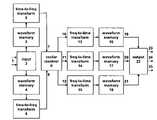
- FIG. 1is a block diagram of a digital signal processing system constructed in accordance with the present invention.
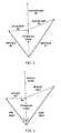
- FIG. 2is a generic graphical representation of the decomposition of the left-input and right-input vectors into the derived-center, derived-left, and derived-right vectors.
- FIG. 3is a graphical representation of the decomposition of the left-input and right-input vectors into the derived-center, derived-left, and derived-right vectors for the specific case in which the phase angle of the derived-center vector is constrained to be halfway between the phase angles of the left-input and right-input vectors.
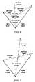
- FIG. 4is a graphical representation of the decomposition of the left-input and right-input vectors into the derived-center, derived-left, and derived-right vectors for the specific case in which the phase angle of the derived-center vector is constrained to be equal to the phase angle of the vector sum of the left-input and right-input vectors.
- FIG. 5is a graphical representation of the decomposition of the left-input and right-input vectors into the derived-center, derived-left, and derived-right vectors for the specific case in which the derived-center vector is equal to a constant “K” times the vector sum of the left-input and right-input vectors, the derived-left vector is equal to the constant “1-K” times the left-input vector, and the derived-right vector is equal to the constant “1-K” times the right-input vector.
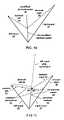
- FIG. 6is a graphical representation of the decomposition of the left-input and right-input vectors into the derived-center, derived-left, and derived-right vectors for the specific case in which the angle between the derived-center vector and the derived-left vector, and the angle between the derived-center vector and the derived-right vector, are both constrained to be 60°.
- FIG. 7is a graphical representation of the decomposition of the left-input and right-input vectors into the derived-center, derived-left, and derived-right vectors for the specific case in which the derived-left vector is constrained to be the negative of the derived-right vector.
- FIG. 8is a graphical representation of the decomposition of the left-input and right-input vectors into the derived-center, derived-left, and derived-right vectors for the specific case in which the shorter of the two input vectors is projected onto the longer.
- FIG. 9is a graphical representation of the decomposition of the left-input and right-input vectors into the derived-center, derived-left, and derived-right vectors for the specific case in which the relative content of the derived-center vector is artificially increased by moving a portion of the left-input channel content to the right-input channel, and vice-versa.
- FIG. 10is a graphical representation of the decomposition of the left-input and right-input vectors into the derived-center, derived-left, and derived-right vectors for the specific case in which the relative content of the derived-center vector is artificially decreased by scaling the derived-center vector by a factor between zero and one prior to extracting the derived-left and derived-right vectors.
- FIG. 11is a graphical representation of the decomposition of the left-input and right-input vectors into the common-inphase, common-quadrature, excess-left, and excess-right vectors for the specific case in which the phase angle of the common-inphase vector is constrained to be equal to the phase angle of the vector sum of the left-input and right-input vectors.
- FIG. 1a simplified block diagram of an implementation on a computer-based information handling system, such as a personal computer, that carries out the present invention is shown in FIG. 1 .
- All of the elements of the personal computer apparatus to be described in the followingare conventional and well known in the art and are described to illustrate the invention, and it is understood that other arrangements for computation in hardware, software, firmware, or any combination thereof may also be utilized in the present invention.
- a general-purpose central processing unitmay be utilized to perform the digital signal processing functions.
- the processingmay be performed employing one or more dedicated processors.
- a special purpose digital signal processormay be employed to perform computationally intensive processing of the digital signal, and with a general purpose central processing unit being used for any further processing and/or storing the processed signal representations in an electronic memory or other digital storage medium.
- the processing functionalitymay be implemented in whole or in part employing a dedicated computing device, hardware logic or finite state machine, which may be realized, for example, in an application-specific integrated circuit (ASIC), programmable logic device (PLD), field programmable gate array (FPGA), or the like.
- ASICapplication-specific integrated circuit
- PLDprogrammable logic device
- FPGAfield programmable gate array
- processoris also intended to encompass a processing function, module, or subroutine, whether implemented in program or software logic or hardware logic, and reference to multiple processors also encompasses such multiple processing functions, modules, or subroutines sharing or implemented in common hardware.
- a digital two-channel stereo time-domain audio signal 1is received at input 2 to the apparatus.
- This signalmay have been transmitted by suitable means directly from a Compact Disc, or it may have been stored as digital data on some other mass storage device such as a computer hard drive or digital magnetic tape, or it may have passed through some prior digital signal processing apparatus, or it may have been obtained directly from the output of analog-to-digital converters.
- the digital dataare passed to waveform memory 3 and 4 where the data are assigned and written sequentially to a number of memory positions corresponding to the number of points in transform computations 5 and 6 .
- pre- and/or post-processing of the datamay be necessary, that some overlap between data points included in a given transform and data points included in the previous transform(s) is desirable, that application of data-tapering windows to the time-domain data, both before and after the direction-of-arrival extraction is performed, is desirable to avoid edge-effects, that zeropadding of the input time-domain data may be necessary in order to avoid circular-convolution effects, and that this all represents standard signal processing practice for transform-domain filtering [4].
- the sampling rateis 44100 Hz
- integer input dataare converted to floating-point
- transformsare of length 32768 with an overlap of 8192 data points from one transform to the next
- a raised-cosine input data tapering window of overall width 16384centered on the splice between the “old” data and the “new” data, is used with 8192 extra zeropadded points on each end
- the computationsare performed in the computer's central processing unit (CPU) and/or floating-point unit (FPU).
- CPUcentral processing unit
- FPUfloating-point unit
- Transform computations 5 and 6convert the blocks of data from the time domain to the frequency domain or, more generally, from the data domain to the transform domain.
- the transformsmay be any of a variety of invertible transforms that can convert data from a one-dimensional data-domain representation to a two-dimensional transform-domain representation, typically but not necessarily the Discrete Fourier Transform that was implemented in the preferred embodiment.
- Other transforms that may be usedinclude, but are not limited to, the Discrete Wavelet Transform, and invertible transforms of the general mathematical form:
- the type of transform, length of the transform, and amount of overlap between subsequent data setsare chosen according to standard signal processing practice as compromises between frequency resolution, ability to respond quickly to changes in signal characteristics, time-domain transient performance, and computational load.
- each transform bin 7 and 8contains a two-dimensional value, interpreted in the conventional signal processing manner as a complex number, representing the signal content for the channel under consideration at the frequency corresponding to the bin.
- Each of these complex valuescan be expressed in the conventional signal processing manner as a vector quantity, in rectangular coordinates as real part and imaginary part, or equivalently in polar coordinates as magnitude and phase.
- the bin data 7 and 8are passed to the vector resolver 9 that performs vector arithmetic upon them.
- the left-input vector 26 and the right-input vector 27are decomposed into three new vectors 28 , 29 , and 30 , nominally designated “derived-center,” “derived-left,” and “derived-right,” respectively.
- the processstarts with the creation of the derived-center vector 28 , which is conceptually a vector representing the signal content that the left and right channels have “in common”.
- Methods for the computation of the derived-center vector 28include, but are not limited to, those shown in FIGS. 3 through 8 . Among these, the methods of FIGS. 3 , 4 , and 5 are the most generally applicable and require the fewest constraints. Because a unique definition for what two vectors have “in common” does not exist, persons skilled in the art will recognize that other mathematically viable schemes could be conceived.
- the phase angleis defined to be the average of the phase angles of the left-input channel and the right-input channel
- the derived-center magnitudeis obtained by doubling (to account for the contribution from each of the two input channels) the perpendicular projection of the shorter of the two input-channel vectors onto the unit vector in the direction of the derived-center vector.
- the derived-left vector 29is computed as “left-input minus 1 ⁇ 2-derived-center” and the derived-right vector 30 is computed as “right-input minus 1 ⁇ 2-derived-center”, using vector arithmetic.
- the derived-left vectoris conceptually the signal content that is unique to the left input channel
- the derived-right vectoris conceptually the signal content that is unique to the right input channel.
- informationis preserved because the vector sum of derived-center 28 , derived-left 29 , and derived-right 30 is exactly equal to the vector sum of left-input 26 and right-input 27 .
- the vector sum of 1 ⁇ 2-derived-center 31 and derived-left 29is exactly equal to left-input 26
- the vector sum of 1 ⁇ 2-derived-center 31 and derived-right 30is exactly equal to right-input 27 .
- the inverse transformsconvert the blocks into the data domain, where they are stored in waveform memories 16 , 17 , and 18 , and then, following standard signal processing practice, post-processed if necessary, aligned, windowed and combined with similar data from previous and subsequent blocks of time in a fashion appropriate for their original overlap, windowing, and zeropadding, to yield contiguous time-domain data streams 19 , 20 , and 21 in each of the three output ( 22 ) channels 23 , 24 , and 25 , respectively.
- a 50% cosine-taper Tukey output data tapering window [5], with rectangle portion of width 16384 and cosine portion of width 16384,is applied to the outputs from the inverse transform computations.
- An overlap-and-add techniqueis utilized for reconstructing the time-domain data because this invention is, in its essence, a form of signal-dependent time-variant linear filtering, and overlap-and-add is superior to overlap-and-save when time-variant filters are used.
- the time dataare converted from floating-point back to integer by appropriate means.
- the resulting data streams 19 , 20 , and 21may be auditioned, stored as digital data, or passed through further signal processing, as desired.
- This techniquemay be varied in order to achieve some desired effects.
- the derived-center channelmay lack content.
- some amount of material from the left-input channelmay be moved into the right-input channel, and vice-versa, forming “modified-left-input” 32 and “modified-right-input” 33 , as shown in FIG. 9 ; an example case identical to FIG. 3 except that 1 ⁇ 4 of left-input is added to right-input, and 1 ⁇ 4 of right-input is added to left-input.
- modified-left-input 32 and modified-right-input 33are utilized by the vector resolver 9 , in place of left-input 26 and right-input 27 , and the process otherwise proceeds as described above.
- the magnitude of derived-center vector 28may be multiplied by a scale-factor between zero and one, yielding “modified-derived-center” 34 , as indicated in FIG. 10 ; an example case identical to FIG. 3 except that the scale-factor is set to 1 ⁇ 2.
- the derived-left vector 29is then computed as “left-input minus 1 ⁇ 2-modified-derived-center” and the derived-right vector 30 is computed as “right-input minus 1 ⁇ 2-modified-derived-center”.
- FIG. 11shows a variant in which the each of the derived-left 29 /derived-right 30 vectors from FIG. 4 is decomposed into two component vectors, at least one of which is orthogonal to the derived-center 28 vector.
- These definitionsresult in four output vectors: common-inphase 35 (equivalent to 1 ⁇ 2-derived-center 28 ), common-quadrature 36 (where the positive direction of the common-quadrature 36 vector has been arbitrarily defined such that it lies on the same side of derived-center 28 as left-input 26 ), excess-left 37 , and excess-right 38 . This contrasts with the standard method of FIGS.
- derived-center 28which only results in three output vectors: derived-center 28 , derived-left 29 , and derived-right 30 .
- the four vectors of FIG. 11are derived in a manner similar to the previous three-vector cases; common-quadrature 36 is equal to derived-left 29 , or the negative of derived-right 30 , whichever is shorter, excess-left 37 is computed as “left-input minus common-inphase minus common-quadrature” (and may, in some cases, be equal to zero), and excess-right 38 is computed as “right-input minus common-inphase plus common-quadrature” (and may, in some cases, be equal to zero).
- each transform bininformation content can be preserved because the vector sum of twice common-inphase 35 , ⁇ common-quadrature 36 , excess-left 37 , and excess-right 38 is exactly equal to the vector sum of left-input 26 and right-input 27 . Furthermore, the vector sum of common-inphase 35 , common-quadrature 36 , and excess-left 37 is exactly equal to left-input 26 , and the vector sum of common-inphase 35 , the negative of common-quadrature 36 , and excess-right 38 is exactly equal to right-input 27 .
- the variant shown in FIG. 11requires four inverse-transform operations to return to the time-domain instead of three, but allows access to both the common-inphase and common-quadrature time-domain data.
- the standard derived-center 28 , derived-left 29 , and derived-right 30 signalscan be obtained from common-inphase 35 , common-quadrature 36 , excess-left 37 , and excess-right 38 as follows: derived-center 28 equals twice common-inphase 35 , derived-left 29 equals excess-left 37 plus common-quadrature 36 , and derived-right 30 equals excess-right 38 minus common-quadrature 36 .
- the set of instructionsmay be stored in another computer readable memory, for example in a hard disk drive or in a removable memory such as an optical disk for utilization in a DVD-ROM or CD-ROM drive, a magnetic medium for utilization in a magnetic media drive, a magneto-optical disk for utilization in a magneto-optical drive, a floptical disk for utilization in a floptical drive, or a memory card for utilization in a card slot.
- the set of instructionscan be stored in the memory of another computer and transmitted over a local area network or a wide area network, such as the Internet, when desired by the user.
- the instructionsmay be transmitted over a network in the form of an applet that is interpreted after transmission to the computer system rather than prior to transmission.
- an appletthat is interpreted after transmission to the computer system rather than prior to transmission.
- the physical storage of the sets of instructions or appletsphysically changes the medium upon which it is stored electrically, magnetically, chemically, physically, optically, or holographically, so that the medium carries computer readable information.
Landscapes
- Physics & Mathematics (AREA)
- Engineering & Computer Science (AREA)
- Acoustics & Sound (AREA)
- Signal Processing (AREA)
- Stereophonic System (AREA)
- Compression, Expansion, Code Conversion, And Decoders (AREA)
Abstract
Description
(where A, B may be real, imaginary, complex, or zero), or equivalent thereto, including the Discrete Fourier Transform, Discrete Cosine Transform, Discrete Sine Transform, Discrete Hartley Transform, and Chirp-Z Transform; and various implementations thereof, including, but not limited to, direct computation using the defining equations, linear-algebra/matrix operations, convolution using FIR or IIR filter structures, polyphase filterbanks, subband filters, and especially the so-called “fast” algorithms such as the Fast Fourier Transform.
- [1] “Surround Sound Past, Present, and Future”, Joseph Hull, Dolby Laboratories Inc., pp. 1-2.
- [2] Hull, op cit., pp. 2-3.
- [3] “Progress in 5-2-5 Matrix Systems”, David Griesinger, Lexicon, pp. 2-3.
- [4] “Digital Signal Processing”, Alan V. Oppenheim and Ronald W. Schafer, Prentice-Hall, Inc., section 3.8.
- [5] “On the use of Windows for Harmonic Analysis with the Discrete Fourier Transform”, Frederic J. Harris, PROCEEDINGS OF THE IEEE, VOL. 66, NO. 1, JANUARY 1978.
Claims (30)
Priority Applications (3)
| Application Number | Priority Date | Filing Date | Title |
|---|---|---|---|
| US10/932,214US7542815B1 (en) | 2003-09-04 | 2004-09-01 | Extraction of left/center/right information from two-channel stereo sources |
| US12/437,253US8086334B2 (en) | 2003-09-04 | 2009-05-07 | Extraction of a multiple channel time-domain output signal from a multichannel signal |
| US13/300,992US8600533B2 (en) | 2003-09-04 | 2011-11-21 | Extraction of a multiple channel time-domain output signal from a multichannel signal |
Applications Claiming Priority (2)
| Application Number | Priority Date | Filing Date | Title |
|---|---|---|---|
| US50010403P | 2003-09-04 | 2003-09-04 | |
| US10/932,214US7542815B1 (en) | 2003-09-04 | 2004-09-01 | Extraction of left/center/right information from two-channel stereo sources |
Related Child Applications (1)
| Application Number | Title | Priority Date | Filing Date |
|---|---|---|---|
| US12/437,253DivisionUS8086334B2 (en) | 2003-09-04 | 2009-05-07 | Extraction of a multiple channel time-domain output signal from a multichannel signal |
Publications (1)
| Publication Number | Publication Date |
|---|---|
| US7542815B1true US7542815B1 (en) | 2009-06-02 |
Family
ID=40672487
Family Applications (3)
| Application Number | Title | Priority Date | Filing Date |
|---|---|---|---|
| US10/932,214Active2027-04-18US7542815B1 (en) | 2003-09-04 | 2004-09-01 | Extraction of left/center/right information from two-channel stereo sources |
| US12/437,253Expired - Fee RelatedUS8086334B2 (en) | 2003-09-04 | 2009-05-07 | Extraction of a multiple channel time-domain output signal from a multichannel signal |
| US13/300,992Expired - LifetimeUS8600533B2 (en) | 2003-09-04 | 2011-11-21 | Extraction of a multiple channel time-domain output signal from a multichannel signal |
Family Applications After (2)
| Application Number | Title | Priority Date | Filing Date |
|---|---|---|---|
| US12/437,253Expired - Fee RelatedUS8086334B2 (en) | 2003-09-04 | 2009-05-07 | Extraction of a multiple channel time-domain output signal from a multichannel signal |
| US13/300,992Expired - LifetimeUS8600533B2 (en) | 2003-09-04 | 2011-11-21 | Extraction of a multiple channel time-domain output signal from a multichannel signal |
Country Status (1)
| Country | Link |
|---|---|
| US (3) | US7542815B1 (en) |
Cited By (23)
| Publication number | Priority date | Publication date | Assignee | Title |
|---|---|---|---|---|
| US20080273707A1 (en)* | 2005-10-28 | 2008-11-06 | Sony United Kingdom Limited | Audio Processing |
| US20080285779A1 (en)* | 2007-05-15 | 2008-11-20 | Funai Electric Co., Ltd. | Television Set |
| US20090252339A1 (en)* | 2005-09-22 | 2009-10-08 | Pioneer Corporation | Signal processing device, signal processing method, signal processing program, and computer readable recording medium |
| US20110116638A1 (en)* | 2009-11-16 | 2011-05-19 | Samsung Electronics Co., Ltd. | Apparatus of generating multi-channel sound signal |
| US20110216907A1 (en)* | 2010-03-03 | 2011-09-08 | William Berardi | Multi-element directional acoustic arrays |
| WO2011107951A1 (en)* | 2010-03-02 | 2011-09-09 | Nokia Corporation | Method and apparatus for upmixing a two-channel audio signal |
| CN102193045A (en)* | 2010-03-19 | 2011-09-21 | 江苏核电有限公司 | Method for checking consistency of analog quantity signal channels |
| US20120010737A1 (en)* | 2009-03-16 | 2012-01-12 | Pioneer Corporation | Audio adjusting device |
| CN102439585A (en)* | 2009-05-11 | 2012-05-02 | 雅基达布鲁公司 | Extraction of common and unique components from pairs of arbitrary signals |
| US20120140930A1 (en)* | 2010-09-30 | 2012-06-07 | Infeneon Technologies Ag | Method for Driving Loudspeakers |
| US8265310B2 (en) | 2010-03-03 | 2012-09-11 | Bose Corporation | Multi-element directional acoustic arrays |
| US8295526B2 (en) | 2008-02-21 | 2012-10-23 | Bose Corporation | Low frequency enclosure for video display devices |
| US8351630B2 (en) | 2008-05-02 | 2013-01-08 | Bose Corporation | Passive directional acoustical radiating |
| US8351629B2 (en) | 2008-02-21 | 2013-01-08 | Robert Preston Parker | Waveguide electroacoustical transducing |
| US8553894B2 (en) | 2010-08-12 | 2013-10-08 | Bose Corporation | Active and passive directional acoustic radiating |
| US20130304244A1 (en)* | 2011-01-20 | 2013-11-14 | Nokia Corporation | Audio alignment apparatus |
| US9451355B1 (en) | 2015-03-31 | 2016-09-20 | Bose Corporation | Directional acoustic device |
| US9820073B1 (en) | 2017-05-10 | 2017-11-14 | Tls Corp. | Extracting a common signal from multiple audio signals |
| US9934772B1 (en) | 2017-07-25 | 2018-04-03 | Louis Yoelin | Self-produced music |
| US10057701B2 (en) | 2015-03-31 | 2018-08-21 | Bose Corporation | Method of manufacturing a loudspeaker |
| US10306391B1 (en)* | 2017-12-18 | 2019-05-28 | Apple Inc. | Stereophonic to monophonic down-mixing |
| US10311848B2 (en) | 2017-07-25 | 2019-06-04 | Louis Yoelin | Self-produced music server and system |
| US10957297B2 (en) | 2017-07-25 | 2021-03-23 | Louis Yoelin | Self-produced music apparatus and method |
Families Citing this family (2)
| Publication number | Priority date | Publication date | Assignee | Title |
|---|---|---|---|---|
| US10863297B2 (en) | 2016-06-01 | 2020-12-08 | Dolby International Ab | Method converting multichannel audio content into object-based audio content and a method for processing audio content having a spatial position |
| WO2021252795A2 (en) | 2020-06-11 | 2021-12-16 | Dolby Laboratories Licensing Corporation | Perceptual optimization of magnitude and phase for time-frequency and softmask source separation systems |
Citations (52)
| Publication number | Priority date | Publication date | Assignee | Title |
|---|---|---|---|---|
| US4024344A (en) | 1974-11-16 | 1977-05-17 | Dolby Laboratories, Inc. | Center channel derivation for stereophonic cinema sound |
| US4074083A (en) | 1974-08-29 | 1978-02-14 | Dolby Laboratories, Inc. | Stereophonic sound system particularly useful in a cinema auditorium |
| US4152542A (en) | 1971-10-06 | 1979-05-01 | Cooper Duane P | Multichannel matrix logic and encoding systems |
| US4293821A (en) | 1979-06-15 | 1981-10-06 | Eprad Incorporated | Audio channel separating apparatus |
| US4594730A (en)* | 1984-04-18 | 1986-06-10 | Rosen Terry K | Apparatus and method for enhancing the perceived sound image of a sound signal by source localization |
| US4685136A (en) | 1984-12-24 | 1987-08-04 | Don Latshaw | Triphonic sound system |
| US4799260A (en) | 1985-03-07 | 1989-01-17 | Dolby Laboratories Licensing Corporation | Variable matrix decoder |
| US4862502A (en) | 1988-01-06 | 1989-08-29 | Lexicon, Inc. | Sound reproduction |
| US4941177A (en) | 1985-03-07 | 1990-07-10 | Dolby Laboratories Licensing Corporation | Variable matrix decoder |
| US5046098A (en) | 1985-03-07 | 1991-09-03 | Dolby Laboratories Licensing Corporation | Variable matrix decoder with three output channels |
| US5136650A (en) | 1991-01-09 | 1992-08-04 | Lexicon, Inc. | Sound reproduction |
| US5216718A (en)* | 1990-04-26 | 1993-06-01 | Sanyo Electric Co., Ltd. | Method and apparatus for processing audio signals |
| US5257313A (en)* | 1990-07-09 | 1993-10-26 | Sony Corporation | Surround audio apparatus |
| US5274740A (en) | 1991-01-08 | 1993-12-28 | Dolby Laboratories Licensing Corporation | Decoder for variable number of channel presentation of multidimensional sound fields |
| US5291557A (en)* | 1992-10-13 | 1994-03-01 | Dolby Laboratories Licensing Corporation | Adaptive rematrixing of matrixed audio signals |
| US5333201A (en)* | 1992-11-12 | 1994-07-26 | Rocktron Corporation | Multi dimensional sound circuit |
| US5588063A (en)* | 1992-10-30 | 1996-12-24 | International Business Machines Corporation | Personal multimedia speaker system |
| US5594800A (en) | 1991-02-15 | 1997-01-14 | Trifield Productions Limited | Sound reproduction system having a matrix converter |
| US5742690A (en)* | 1994-05-18 | 1998-04-21 | International Business Machine Corp. | Personal multimedia speaker system |
| US5796844A (en) | 1996-07-19 | 1998-08-18 | Lexicon | Multichannel active matrix sound reproduction with maximum lateral separation |
| US5818941A (en)* | 1995-11-22 | 1998-10-06 | Sony Corporation | Configurable cinema sound system |
| US5870480A (en) | 1996-07-19 | 1999-02-09 | Lexicon | Multichannel active matrix encoder and decoder with maximum lateral separation |
| US5912976A (en) | 1996-11-07 | 1999-06-15 | Srs Labs, Inc. | Multi-channel audio enhancement system for use in recording and playback and methods for providing same |
| US5987141A (en) | 1992-08-28 | 1999-11-16 | Thomson Consumer Electronics, Inc. | Stereo expander |
| US5995631A (en)* | 1996-07-23 | 1999-11-30 | Kabushiki Kaisha Kawai Gakki Seisakusho | Sound image localization apparatus, stereophonic sound image enhancement apparatus, and sound image control system |
| US6038323A (en)* | 1997-11-17 | 2000-03-14 | Harman Motive Inc. | Stereophonic image enhancement system for use in automobiles |
| US6169812B1 (en)* | 1998-10-14 | 2001-01-02 | Francis Allen Miller | Point source speaker system |
| US6292570B1 (en) | 1998-02-13 | 2001-09-18 | U.S. Philips Corporation | Surround sound |
| US20010047256A1 (en)* | 1993-12-07 | 2001-11-29 | Katsuaki Tsurushima | Multi-format recording medium |
| US20020006206A1 (en)* | 1994-03-08 | 2002-01-17 | Sonics Associates, Inc. | Center channel enhancement of virtual sound images |
| US20020103635A1 (en)* | 2001-01-26 | 2002-08-01 | Mesarovic Vladimir Z. | Efficient PCM buffer |
| US20020122562A1 (en)* | 1997-04-16 | 2002-09-05 | Robert Brennan | Filterbank structure and method for filtering and separating an information signal into different bands, particularly for audio signals in hearing aids |
| US6496584B2 (en) | 2000-07-19 | 2002-12-17 | Koninklijke Philips Electronics N.V. | Multi-channel stereo converter for deriving a stereo surround and/or audio center signal |
| US6507659B1 (en)* | 1999-01-25 | 2003-01-14 | Cascade Audio, Inc. | Microphone apparatus for producing signals for surround reproduction |
| US20030026441A1 (en)* | 2001-05-04 | 2003-02-06 | Christof Faller | Perceptual synthesis of auditory scenes |
| US20030083024A1 (en)* | 2001-10-30 | 2003-05-01 | Lawrence Richenstein | Multiple channel wireless communication system |
| US20030147543A1 (en)* | 2002-02-04 | 2003-08-07 | Yamaha Corporation | Audio amplifier unit |
| US20030185411A1 (en)* | 2002-04-02 | 2003-10-02 | University Of Washington | Single channel sound separation |
| US6631193B1 (en)* | 1999-01-07 | 2003-10-07 | Kentech | Audio system enhancement using psycho acoustic matrix |
| US6639939B1 (en)* | 1997-05-20 | 2003-10-28 | Axonn L.L.C. | Direct sequence spread spectrum method computer-based product apparatus and system tolerant to frequency reference offset |
| US6665409B1 (en)* | 1999-04-12 | 2003-12-16 | Cirrus Logic, Inc. | Methods for surround sound simulation and circuits and systems using the same |
| US6691073B1 (en)* | 1998-06-18 | 2004-02-10 | Clarity Technologies Inc. | Adaptive state space signal separation, discrimination and recovery |
| US20040037440A1 (en)* | 2001-07-11 | 2004-02-26 | Croft Iii James J. | Dynamic power sharing in a multi-channel sound system |
| US6725108B1 (en)* | 1999-01-28 | 2004-04-20 | International Business Machines Corporation | System and method for interpretation and visualization of acoustic spectra, particularly to discover the pitch and timbre of musical sounds |
| US20040114939A1 (en)* | 2002-12-11 | 2004-06-17 | Taylor Michael George | Coherent optical detection and signal processing method and system |
| US20040142748A1 (en)* | 2003-01-16 | 2004-07-22 | Loose Timothy C. | Gaming system with surround sound |
| US20040157555A1 (en)* | 2001-10-30 | 2004-08-12 | Lawrence Richenstein | Multiple channel wireless communication system |
| US20050276420A1 (en)* | 2001-02-07 | 2005-12-15 | Dolby Laboratories Licensing Corporation | Audio channel spatial translation |
| US20060098827A1 (en)* | 2002-06-05 | 2006-05-11 | Thomas Paddock | Acoustical virtual reality engine and advanced techniques for enhancing delivered sound |
| US7113609B1 (en)* | 1999-06-04 | 2006-09-26 | Zoran Corporation | Virtual multichannel speaker system |
| US7254239B2 (en)* | 2001-02-09 | 2007-08-07 | Thx Ltd. | Sound system and method of sound reproduction |
| US7257231B1 (en)* | 2002-06-04 | 2007-08-14 | Creative Technology Ltd. | Stream segregation for stereo signals |
Family Cites Families (21)
| Publication number | Priority date | Publication date | Assignee | Title |
|---|---|---|---|---|
| US114939A (en)* | 1871-05-16 | Improvement in pipe-cutters | ||
| US157555A (en)* | 1874-12-08 | Improvement in fare-boxes | ||
| US98827A (en)* | 1870-01-11 | Improvement in hinges | ||
| US122562A (en)* | 1872-01-09 | Improvement in clapboarding | ||
| US83024A (en)* | 1868-10-13 | Improvement in liquid-samplers | ||
| US147543A (en)* | 1874-02-17 | Improvement in piston-packings | ||
| US185411A (en)* | 1876-12-19 | Improvement in weft-thread-knitting machines | ||
| US26441A (en)* | 1859-12-13 | Island | ||
| US37440A (en)* | 1863-01-20 | Improvement in grain-separators | ||
| US142748A (en)* | 1873-09-09 | Improvement in bee-hives | ||
| US276420A (en)* | 1883-04-24 | Variable coupling-joint for shafting | ||
| US6206A (en)* | 1849-03-20 | Self-adjusting railroad-switch | ||
| US47256A (en)* | 1865-04-11 | Improved apparatus for carbureting air | ||
| US3835255A (en)* | 1971-09-30 | 1974-09-10 | Columbia Broadcasting Syst Inc | Matrix decoders for quadraphonic sound system |
| US5610986A (en)* | 1994-03-07 | 1997-03-11 | Miles; Michael T. | Linear-matrix audio-imaging system and image analyzer |
| US6711266B1 (en)* | 1997-02-07 | 2004-03-23 | Bose Corporation | Surround sound channel encoding and decoding |
| GB2374772B (en)* | 2001-01-29 | 2004-12-29 | Hewlett Packard Co | Audio user interface |
| DE10129240A1 (en)* | 2001-06-18 | 2003-01-02 | Fraunhofer Ges Forschung | Method and device for processing discrete-time audio samples |
| AU2003222397A1 (en) | 2003-04-30 | 2004-11-23 | Nokia Corporation | Support of a multichannel audio extension |
| US9088855B2 (en) | 2006-05-17 | 2015-07-21 | Creative Technology Ltd | Vector-space methods for primary-ambient decomposition of stereo audio signals |
| US8379868B2 (en) | 2006-05-17 | 2013-02-19 | Creative Technology Ltd | Spatial audio coding based on universal spatial cues |
- 2004
- 2004-09-01USUS10/932,214patent/US7542815B1/enactiveActive
- 2009
- 2009-05-07USUS12/437,253patent/US8086334B2/ennot_activeExpired - Fee Related
- 2011
- 2011-11-21USUS13/300,992patent/US8600533B2/ennot_activeExpired - Lifetime
Patent Citations (55)
| Publication number | Priority date | Publication date | Assignee | Title |
|---|---|---|---|---|
| US4152542A (en) | 1971-10-06 | 1979-05-01 | Cooper Duane P | Multichannel matrix logic and encoding systems |
| US4074083A (en) | 1974-08-29 | 1978-02-14 | Dolby Laboratories, Inc. | Stereophonic sound system particularly useful in a cinema auditorium |
| US4024344A (en) | 1974-11-16 | 1977-05-17 | Dolby Laboratories, Inc. | Center channel derivation for stereophonic cinema sound |
| US4293821A (en) | 1979-06-15 | 1981-10-06 | Eprad Incorporated | Audio channel separating apparatus |
| US4594730A (en)* | 1984-04-18 | 1986-06-10 | Rosen Terry K | Apparatus and method for enhancing the perceived sound image of a sound signal by source localization |
| US4685136A (en) | 1984-12-24 | 1987-08-04 | Don Latshaw | Triphonic sound system |
| US4941177A (en) | 1985-03-07 | 1990-07-10 | Dolby Laboratories Licensing Corporation | Variable matrix decoder |
| US5046098A (en) | 1985-03-07 | 1991-09-03 | Dolby Laboratories Licensing Corporation | Variable matrix decoder with three output channels |
| US4799260A (en) | 1985-03-07 | 1989-01-17 | Dolby Laboratories Licensing Corporation | Variable matrix decoder |
| US4862502A (en) | 1988-01-06 | 1989-08-29 | Lexicon, Inc. | Sound reproduction |
| US5216718A (en)* | 1990-04-26 | 1993-06-01 | Sanyo Electric Co., Ltd. | Method and apparatus for processing audio signals |
| US5257313A (en)* | 1990-07-09 | 1993-10-26 | Sony Corporation | Surround audio apparatus |
| US5274740A (en) | 1991-01-08 | 1993-12-28 | Dolby Laboratories Licensing Corporation | Decoder for variable number of channel presentation of multidimensional sound fields |
| US5400433A (en) | 1991-01-08 | 1995-03-21 | Dolby Laboratories Licensing Corporation | Decoder for variable-number of channel presentation of multidimensional sound fields |
| US5136650A (en) | 1991-01-09 | 1992-08-04 | Lexicon, Inc. | Sound reproduction |
| US5594800A (en) | 1991-02-15 | 1997-01-14 | Trifield Productions Limited | Sound reproduction system having a matrix converter |
| US5987141A (en) | 1992-08-28 | 1999-11-16 | Thomson Consumer Electronics, Inc. | Stereo expander |
| US5291557A (en)* | 1992-10-13 | 1994-03-01 | Dolby Laboratories Licensing Corporation | Adaptive rematrixing of matrixed audio signals |
| US5588063A (en)* | 1992-10-30 | 1996-12-24 | International Business Machines Corporation | Personal multimedia speaker system |
| US5333201A (en)* | 1992-11-12 | 1994-07-26 | Rocktron Corporation | Multi dimensional sound circuit |
| US20010047256A1 (en)* | 1993-12-07 | 2001-11-29 | Katsuaki Tsurushima | Multi-format recording medium |
| US6853732B2 (en)* | 1994-03-08 | 2005-02-08 | Sonics Associates, Inc. | Center channel enhancement of virtual sound images |
| US20020006206A1 (en)* | 1994-03-08 | 2002-01-17 | Sonics Associates, Inc. | Center channel enhancement of virtual sound images |
| US5742690A (en)* | 1994-05-18 | 1998-04-21 | International Business Machine Corp. | Personal multimedia speaker system |
| US5956411A (en)* | 1994-05-18 | 1999-09-21 | International Business Machines Corporation | Personal multimedia speaker system |
| US5818941A (en)* | 1995-11-22 | 1998-10-06 | Sony Corporation | Configurable cinema sound system |
| US5796844A (en) | 1996-07-19 | 1998-08-18 | Lexicon | Multichannel active matrix sound reproduction with maximum lateral separation |
| US5870480A (en) | 1996-07-19 | 1999-02-09 | Lexicon | Multichannel active matrix encoder and decoder with maximum lateral separation |
| US5995631A (en)* | 1996-07-23 | 1999-11-30 | Kabushiki Kaisha Kawai Gakki Seisakusho | Sound image localization apparatus, stereophonic sound image enhancement apparatus, and sound image control system |
| US5912976A (en) | 1996-11-07 | 1999-06-15 | Srs Labs, Inc. | Multi-channel audio enhancement system for use in recording and playback and methods for providing same |
| US20020122562A1 (en)* | 1997-04-16 | 2002-09-05 | Robert Brennan | Filterbank structure and method for filtering and separating an information signal into different bands, particularly for audio signals in hearing aids |
| US6639939B1 (en)* | 1997-05-20 | 2003-10-28 | Axonn L.L.C. | Direct sequence spread spectrum method computer-based product apparatus and system tolerant to frequency reference offset |
| US6038323A (en)* | 1997-11-17 | 2000-03-14 | Harman Motive Inc. | Stereophonic image enhancement system for use in automobiles |
| US6292570B1 (en) | 1998-02-13 | 2001-09-18 | U.S. Philips Corporation | Surround sound |
| US6691073B1 (en)* | 1998-06-18 | 2004-02-10 | Clarity Technologies Inc. | Adaptive state space signal separation, discrimination and recovery |
| US6169812B1 (en)* | 1998-10-14 | 2001-01-02 | Francis Allen Miller | Point source speaker system |
| US6631193B1 (en)* | 1999-01-07 | 2003-10-07 | Kentech | Audio system enhancement using psycho acoustic matrix |
| US6507659B1 (en)* | 1999-01-25 | 2003-01-14 | Cascade Audio, Inc. | Microphone apparatus for producing signals for surround reproduction |
| US6725108B1 (en)* | 1999-01-28 | 2004-04-20 | International Business Machines Corporation | System and method for interpretation and visualization of acoustic spectra, particularly to discover the pitch and timbre of musical sounds |
| US6665409B1 (en)* | 1999-04-12 | 2003-12-16 | Cirrus Logic, Inc. | Methods for surround sound simulation and circuits and systems using the same |
| US7113609B1 (en)* | 1999-06-04 | 2006-09-26 | Zoran Corporation | Virtual multichannel speaker system |
| US6496584B2 (en) | 2000-07-19 | 2002-12-17 | Koninklijke Philips Electronics N.V. | Multi-channel stereo converter for deriving a stereo surround and/or audio center signal |
| US20020103635A1 (en)* | 2001-01-26 | 2002-08-01 | Mesarovic Vladimir Z. | Efficient PCM buffer |
| US20050276420A1 (en)* | 2001-02-07 | 2005-12-15 | Dolby Laboratories Licensing Corporation | Audio channel spatial translation |
| US7254239B2 (en)* | 2001-02-09 | 2007-08-07 | Thx Ltd. | Sound system and method of sound reproduction |
| US20030026441A1 (en)* | 2001-05-04 | 2003-02-06 | Christof Faller | Perceptual synthesis of auditory scenes |
| US20040037440A1 (en)* | 2001-07-11 | 2004-02-26 | Croft Iii James J. | Dynamic power sharing in a multi-channel sound system |
| US20040157555A1 (en)* | 2001-10-30 | 2004-08-12 | Lawrence Richenstein | Multiple channel wireless communication system |
| US20030083024A1 (en)* | 2001-10-30 | 2003-05-01 | Lawrence Richenstein | Multiple channel wireless communication system |
| US20030147543A1 (en)* | 2002-02-04 | 2003-08-07 | Yamaha Corporation | Audio amplifier unit |
| US20030185411A1 (en)* | 2002-04-02 | 2003-10-02 | University Of Washington | Single channel sound separation |
| US7257231B1 (en)* | 2002-06-04 | 2007-08-14 | Creative Technology Ltd. | Stream segregation for stereo signals |
| US20060098827A1 (en)* | 2002-06-05 | 2006-05-11 | Thomas Paddock | Acoustical virtual reality engine and advanced techniques for enhancing delivered sound |
| US20040114939A1 (en)* | 2002-12-11 | 2004-06-17 | Taylor Michael George | Coherent optical detection and signal processing method and system |
| US20040142748A1 (en)* | 2003-01-16 | 2004-07-22 | Loose Timothy C. | Gaming system with surround sound |
Non-Patent Citations (9)
| Title |
|---|
| Avendano et al., "A Frequency-Domain Approach to Multichannel Upmix," J. Audio Eng. Soc., vol. 52, No. 7/8, pp. 740-749 (Jul./Aug. 2004). |
| Feiten, "Pseudo-Stereo and Surround-Sound by Matched FIR-Filters," Audio Engineering Society Preprint No. 4222, pp. 1-11 (1996). |
| Griesinger, "Progress in 5-2-5 Matrix Systems," pp. 1-41 (date unknown). |
| Hull, "Surround Sound Past, Present, and Future: A History of Multichannel Audio from Mag Stripe to Dolby Digital," pp. 1-6 (1999). |
| Irwan et al., "Two-to-Five Channel Sound Processing," J. Audio Eng. Soc., vol. 50, No. 11, pp. 914-926 (Nov. 2002). |
| Scheiber, "Analyzing Phase-Amplitude Matrices," J. Audio Eng. Soc., vol. 19, No. 10, pp. 835-839 (Nov. 1971). |
| Tappan, "An Improvement in Simulated Three-Channel Stereo," IRE Transactions on Audio, pp. 72-79 (May-Jun. 1961). |
| Ten Kate et al., "A New Surround-Stereo-Surround Coding Technique," J. Audio Eng. Soc., vol. 40, No. 5, pp. 376-383 (May 1992). |
| Willcocks, "Surround Sound in the Eighties-Advances in Decoder Technology," Audio Engineering Society Preprint No. 2017, pp. 1-34 (1983). |
Cited By (32)
| Publication number | Priority date | Publication date | Assignee | Title |
|---|---|---|---|---|
| US20090252339A1 (en)* | 2005-09-22 | 2009-10-08 | Pioneer Corporation | Signal processing device, signal processing method, signal processing program, and computer readable recording medium |
| US20080273707A1 (en)* | 2005-10-28 | 2008-11-06 | Sony United Kingdom Limited | Audio Processing |
| US20080285779A1 (en)* | 2007-05-15 | 2008-11-20 | Funai Electric Co., Ltd. | Television Set |
| US8233647B2 (en)* | 2007-05-15 | 2012-07-31 | Funai Electric Co., Ltd. | Television set |
| US8295526B2 (en) | 2008-02-21 | 2012-10-23 | Bose Corporation | Low frequency enclosure for video display devices |
| US8351629B2 (en) | 2008-02-21 | 2013-01-08 | Robert Preston Parker | Waveguide electroacoustical transducing |
| US8351630B2 (en) | 2008-05-02 | 2013-01-08 | Bose Corporation | Passive directional acoustical radiating |
| US20120010737A1 (en)* | 2009-03-16 | 2012-01-12 | Pioneer Corporation | Audio adjusting device |
| CN102439585A (en)* | 2009-05-11 | 2012-05-02 | 雅基达布鲁公司 | Extraction of common and unique components from pairs of arbitrary signals |
| EP2430566A4 (en)* | 2009-05-11 | 2014-04-02 | Akita Blue Inc | Extraction of common and unique components from pairs of arbitrary signals |
| CN102439585B (en)* | 2009-05-11 | 2015-04-22 | 雅基达布鲁公司 | Extract common and unique components from arbitrary signal pairs |
| US9154895B2 (en) | 2009-11-16 | 2015-10-06 | Samsung Electronics Co., Ltd. | Apparatus of generating multi-channel sound signal |
| US20110116638A1 (en)* | 2009-11-16 | 2011-05-19 | Samsung Electronics Co., Ltd. | Apparatus of generating multi-channel sound signal |
| US9313598B2 (en)* | 2010-03-02 | 2016-04-12 | Nokia Technologies Oy | Method and apparatus for stereo to five channel upmix |
| US20120308015A1 (en)* | 2010-03-02 | 2012-12-06 | Nokia Corporation | Method and apparatus for stereo to five channel upmix |
| EP2543199A4 (en)* | 2010-03-02 | 2014-03-12 | Nokia Corp | METHOD AND APPARATUS FOR MIXING LIFT OF TWO-CHANNEL AUDIO SIGNAL |
| WO2011107951A1 (en)* | 2010-03-02 | 2011-09-09 | Nokia Corporation | Method and apparatus for upmixing a two-channel audio signal |
| US20110216907A1 (en)* | 2010-03-03 | 2011-09-08 | William Berardi | Multi-element directional acoustic arrays |
| US8265310B2 (en) | 2010-03-03 | 2012-09-11 | Bose Corporation | Multi-element directional acoustic arrays |
| US8139774B2 (en) | 2010-03-03 | 2012-03-20 | Bose Corporation | Multi-element directional acoustic arrays |
| CN102193045A (en)* | 2010-03-19 | 2011-09-21 | 江苏核电有限公司 | Method for checking consistency of analog quantity signal channels |
| US8553894B2 (en) | 2010-08-12 | 2013-10-08 | Bose Corporation | Active and passive directional acoustic radiating |
| US20120140930A1 (en)* | 2010-09-30 | 2012-06-07 | Infeneon Technologies Ag | Method for Driving Loudspeakers |
| US8917875B2 (en)* | 2010-09-30 | 2014-12-23 | Infineon Technologies Ag | Method for driving loudspeakers |
| US20130304244A1 (en)* | 2011-01-20 | 2013-11-14 | Nokia Corporation | Audio alignment apparatus |
| US9451355B1 (en) | 2015-03-31 | 2016-09-20 | Bose Corporation | Directional acoustic device |
| US10057701B2 (en) | 2015-03-31 | 2018-08-21 | Bose Corporation | Method of manufacturing a loudspeaker |
| US9820073B1 (en) | 2017-05-10 | 2017-11-14 | Tls Corp. | Extracting a common signal from multiple audio signals |
| US9934772B1 (en) | 2017-07-25 | 2018-04-03 | Louis Yoelin | Self-produced music |
| US10311848B2 (en) | 2017-07-25 | 2019-06-04 | Louis Yoelin | Self-produced music server and system |
| US10957297B2 (en) | 2017-07-25 | 2021-03-23 | Louis Yoelin | Self-produced music apparatus and method |
| US10306391B1 (en)* | 2017-12-18 | 2019-05-28 | Apple Inc. | Stereophonic to monophonic down-mixing |
Also Published As
| Publication number | Publication date |
|---|---|
| US20120070006A1 (en) | 2012-03-22 |
| US8600533B2 (en) | 2013-12-03 |
| US20090287328A1 (en) | 2009-11-19 |
| US8086334B2 (en) | 2011-12-27 |
Similar Documents
| Publication | Publication Date | Title |
|---|---|---|
| US8600533B2 (en) | Extraction of a multiple channel time-domain output signal from a multichannel signal | |
| EP1706865B1 (en) | Apparatus and method for constructing a multi-channel output signal or for generating a downmix signal | |
| US9088855B2 (en) | Vector-space methods for primary-ambient decomposition of stereo audio signals | |
| US11641560B2 (en) | Binaural dialogue enhancement | |
| KR102380192B1 (en) | Binaural rendering method and apparatus for decoding multi channel audio | |
| EP3357259B1 (en) | Method and apparatus for generating 3d audio content from two-channel stereo content | |
| WO2009046225A2 (en) | Correlation-based method for ambience extraction from two-channel audio signals | |
| CN1985303A (en) | Apparatus and method for generating a multi-channel output signal | |
| US20050276430A1 (en) | Fast headphone virtualization | |
| US9913036B2 (en) | Apparatus and method and computer program for generating a stereo output signal for providing additional output channels | |
| EP3488623B1 (en) | Audio object clustering based on renderer-aware perceptual difference | |
| EP4483588A1 (en) | Upmixing systems and methods for extending stereo signals to multi-channel formats | |
| US20120059498A1 (en) | Extraction of common and unique components from pairs of arbitrary signals | |
| JPWO2010119572A1 (en) | Surround signal generating apparatus, surround signal generating method, and surround signal generating program | |
| US20250061901A1 (en) | Multi channel audio processing for upmixing/remixing/downmixing applications | |
| He | Time-Shifting-Based Primary Ambient Extraction | |
| JPH06153299A (en) | Level display device |
Legal Events
| Date | Code | Title | Description |
|---|---|---|---|
| AS | Assignment | Owner name:XIFI CORP., NEW HAMPSHIRE Free format text:ASSIGNMENT OF ASSIGNORS INTEREST;ASSIGNOR:BERCHIN, GREGORY J.;REEL/FRAME:015765/0392 Effective date:20040826 | |
| AS | Assignment | Owner name:BERCHIN, GREGORY J., VERMONT Free format text:ASSIGNMENT OF ASSIGNORS INTEREST;ASSIGNOR:XIFI CORPORATION;REEL/FRAME:020610/0212 Effective date:20080227 | |
| AS | Assignment | Owner name:AKITA BLUE, INC., NEW HAMPSHIRE Free format text:ASSIGNMENT OF ASSIGNORS INTEREST;ASSIGNOR:BERCHIN, GEORGE;REEL/FRAME:021466/0758 Effective date:20080828 | |
| AS | Assignment | Owner name:AKITA BLUE, INC., NEW HAMPSHIRE Free format text:CORRECTIVE ASSIGNMENT TO CORRECT THE FIRST NAME OF INVENTOR PREVIOUSLY RECORDED ON REEL 021466 FRAME 0758;ASSIGNOR:BERCHIN, GREGORY;REEL/FRAME:021548/0576 Effective date:20080828 | |
| STCF | Information on status: patent grant | Free format text:PATENTED CASE | |
| FEPP | Fee payment procedure | Free format text:PAYOR NUMBER ASSIGNED (ORIGINAL EVENT CODE: ASPN); ENTITY STATUS OF PATENT OWNER: SMALL ENTITY | |
| FPAY | Fee payment | Year of fee payment:4 | |
| FPAY | Fee payment | Year of fee payment:8 | |
| MAFP | Maintenance fee payment | Free format text:PAYMENT OF MAINTENANCE FEE, 12TH YR, SMALL ENTITY (ORIGINAL EVENT CODE: M2553); ENTITY STATUS OF PATENT OWNER: SMALL ENTITY Year of fee payment:12 |