US7542806B1 - Envelope-based amplitude mapping for cochlear implant stimulus - Google Patents
Envelope-based amplitude mapping for cochlear implant stimulusDownload PDFInfo
- Publication number
- US7542806B1 US7542806B1US11/346,067US34606706AUS7542806B1US 7542806 B1US7542806 B1US 7542806B1US 34606706 AUS34606706 AUS 34606706AUS 7542806 B1US7542806 B1US 7542806B1
- Authority
- US
- United States
- Prior art keywords
- signal
- envelope
- mapping
- computing
- decimated
- Prior art date
- Legal status (The legal status is an assumption and is not a legal conclusion. Google has not performed a legal analysis and makes no representation as to the accuracy of the status listed.)
- Expired - Fee Related, expires
Links
- 238000013507mappingMethods0.000titleclaimsabstractdescription43
- 239000007943implantSubstances0.000title1
- 230000000638stimulationEffects0.000claimsabstractdescription23
- 238000001914filtrationMethods0.000claims2
- 230000013707sensory perception of soundEffects0.000abstractdescription12
- 210000003477cochleaAnatomy0.000abstractdescription10
- 230000006835compressionEffects0.000abstractdescription3
- 238000007906compressionMethods0.000abstractdescription3
- 230000000694effectsEffects0.000abstractdescription2
- 230000004075alterationEffects0.000abstract1
- 238000012545processingMethods0.000description18
- 230000006870functionEffects0.000description12
- 238000000034methodMethods0.000description11
- 230000008569processEffects0.000description10
- 210000000860cochlear nerveAnatomy0.000description7
- 230000008901benefitEffects0.000description6
- 210000002768hair cellAnatomy0.000description6
- 206010011878DeafnessDiseases0.000description5
- 230000004044responseEffects0.000description5
- 208000000781Conductive Hearing LossDiseases0.000description3
- 206010010280Conductive deafnessDiseases0.000description3
- 208000023563conductive hearing loss diseaseDiseases0.000description3
- 208000016354hearing loss diseaseDiseases0.000description3
- 210000002569neuronAnatomy0.000description3
- 230000009466transformationEffects0.000description3
- 206010011891Deafness neurosensoryDiseases0.000description2
- 208000009966Sensorineural Hearing LossDiseases0.000description2
- 210000004556brainAnatomy0.000description2
- 210000004027cellAnatomy0.000description2
- 230000006378damageEffects0.000description2
- 231100000888hearing lossToxicity0.000description2
- 230000010370hearing lossEffects0.000description2
- 238000005259measurementMethods0.000description2
- 208000023573sensorineural hearing loss diseaseDiseases0.000description2
- 230000004936stimulating effectEffects0.000description2
- 210000003484anatomyAnatomy0.000description1
- 238000013459approachMethods0.000description1
- 210000003030auditory receptor cellAnatomy0.000description1
- 239000003990capacitorSubstances0.000description1
- 231100000895deafnessToxicity0.000description1
- 230000007423decreaseEffects0.000description1
- 230000002950deficientEffects0.000description1
- 230000001419dependent effectEffects0.000description1
- 238000013461designMethods0.000description1
- 238000001514detection methodMethods0.000description1
- 238000011161developmentMethods0.000description1
- 238000010586diagramMethods0.000description1
- 238000004146energy storageMethods0.000description1
- 239000000835fiberSubstances0.000description1
- 210000003128headAnatomy0.000description1
- 238000002513implantationMethods0.000description1
- 230000006872improvementEffects0.000description1
- 230000007774longtermEffects0.000description1
- 230000007246mechanismEffects0.000description1
- 238000012986modificationMethods0.000description1
- 230000004048modificationEffects0.000description1
- 230000037361pathwayEffects0.000description1
- 230000008447perceptionEffects0.000description1
- 230000009467reductionEffects0.000description1
- 230000000717retained effectEffects0.000description1
- 231100000879sensorineural hearing lossToxicity0.000description1
- 238000004088simulationMethods0.000description1
- 238000001228spectrumMethods0.000description1
- 238000001356surgical procedureMethods0.000description1
- 238000012360testing methodMethods0.000description1
- 230000000451tissue damageEffects0.000description1
- 231100000827tissue damageToxicity0.000description1
- 230000002463transducing effectEffects0.000description1
Images


Classifications
- A—HUMAN NECESSITIES
- A61—MEDICAL OR VETERINARY SCIENCE; HYGIENE
- A61N—ELECTROTHERAPY; MAGNETOTHERAPY; RADIATION THERAPY; ULTRASOUND THERAPY
- A61N1/00—Electrotherapy; Circuits therefor
- A61N1/18—Applying electric currents by contact electrodes
- A61N1/32—Applying electric currents by contact electrodes alternating or intermittent currents
- A61N1/36—Applying electric currents by contact electrodes alternating or intermittent currents for stimulation
- A61N1/36036—Applying electric currents by contact electrodes alternating or intermittent currents for stimulation of the outer, middle or inner ear
- A61N1/36038—Cochlear stimulation
Definitions
- the present inventionrelates to cochlear prosthesis used to electrically stimulate the auditory nerve, and more particularly to a process for mapping a signal level into a stimulation current level.
- Hearing losswhich may be due to many different causes, is generally of two types: conductive and sensorineural.
- conductive hearing lossoccurs where the normal mechanical pathways for sound to reach the hair cells in the cochlea are impeded, for example, by damage to the ossicles.
- Conductive hearing lossmay often be helped by use of conventional hearing aids, which amplify sound so that acoustic information does reach the cochlea and the hair cells.
- Some types of conductive hearing lossare also amenable to alleviation by surgical procedures.
- cochlear stimulation systemsor cochlear prosthesis—have been developed which seek to bypass the hair cells in the cochlear (the hair cells are located in the vicinity of the radially outer wall of the cochlea) by presenting electrical stimulation to the auditory nerve fibers directly, leading to the perception of sound in the brain and an at least partial restoration of hearing function.
- the common denominators in most of these cochlear prosthesis systemshave been the implantation, into the cochlea, of electrodes, and a suitable external source of an electrical signal for the electrodes.
- a cochlear prosthesisoperates by direct electrical stimulation of the auditory nerve cells, bypassing the defective cochlear hair cells that normally transduce acoustic energy into electrical activity in such nerve cells.
- the electronic circuitry and the electrode array of the cochlear prosthesisperform the function of separating the acoustic signal into a number of parallel channels of information, each representing the intensity of a narrow band of frequencies within the acoustic spectrum.
- the electrode arraywould convey each channel of information selectively to the subset of auditory nerve cells that normally transmitted information about that frequency band to the brain.
- Those nerve cellsare arranged in an orderly tonotopic sequence, from high frequencies at the basal end of the cochlear spiral to progressively lower frequencies towards the apex, and ideally the entire length of the cochlea would be stimulated to provide a full frequency range of hearing. In practice, this ideal is not achieved, because of the anatomy of the cochlea which decreases in diameter from the base to the apex, and exhibits variations between patients. Because of these difficulties, known electrodes can only be promoted to the second turn of the cochlea at best.
- the signal provided to the electrode arrayis generated by a signal processing component of the Implantable Cochlear Stimulation (ICS) system.
- ICSImplantable Cochlear Stimulation
- the acoustic signalis first processed by a family of parallel bandpass filters.
- the output of each bandpass filteris independently amplitude mapped into a simulation level using a mapping consistent with normal perception.
- the mappingis a compressive mapping that is based on the log of the magnitude of each independent sample of the outputs of the band pass filters.
- the logis taken of the magnitude of each sample, then multiplied by a first scalar and added to a second scalar, and the sign of each sample is then applied to the compressed value.
- the log functioncan result in a DC component in the resulting signal, distorts sinusoidal inputs, and is computationally intensive.
- the DC componentarises from the asymmetry of the input waveform.
- the signalis processed before the amplitude mapping to remove DC bias, and as a result the total area under the waveform, at the output of the bandpass filters, sums to zero.
- the compressive nature of the log functionreduces narrow high peaks much more than wide low peaks, and thereby creates a DC bias.
- a wideband speech signalis very asymmetric by nature, so the likelihood of generating such a DC bias is high.
- the presence of the DC biasposes a potential for tissue damage after long term use, and may cause the charge in a capacitor typically, used for energy storage in the implantable stimulation circuit, to grow large resulting in undesirable nonlinear behavior.
- the shape of a waveform processed by the amplitude mappingmay be distorted by the compression. For example, samples from the peak of a sinusoidal waveform are compressed more than samples between the peaks, and as a result the sinusoid becomes more like a square wave with rounded corners than like a sinusoid.
- sine wavesare used as the stimulating signals for each electrode. The frequency of each sine wave is selected as the center frequency of the band pass filter that processes the signal for the corresponding electrode in normal system operation.
- the perceived loudnessmay not be the same as with the original sinusoid.
- the peak stimulation currents of the original sinusoid and the compressed sinusoidare the same, the amplitude mapping brings up the “shoulders” on the compressed sinusoid, making it more like a square wave with rounded corners.
- charge per phaseraises, which results in the perceived loudness increasing. This increase in perceived loudness may be significant for patients with a narrow dynamic hearing range.
- BTEBehind-The-Ear
- a BTE ICS systemis described in U.S. Pat. No. 5,824,022 issued Oct. 20, 1998 for ‘Cochlear stimulation system employing behind-the-ear speech processor with remote control.’
- Behind-the-ear speech processorsoffer several advantages, but their small size limits the size of the battery they may carry (which in turn limits the capacity of the battery.) The small battery size results in a requirement for very low power consumption. Processing, such as that required by known amplitude mapping methods, work against the need to reduce power dissipation.
- the '022 patentis herein incorporated by reference.
- An improvement to the current compressive processingis needed to both improve performance, and to reduce the power consumption required for signal processing.
- the present inventionaddresses the above and other needs by replacing the known sample by sample amplitude mapping process in Implantable Cochlear Stimulation (ICS) systems with an envelope based amplitude mapping process.
- the envelope based amplitude mapping processesoperate in parallel on the filtered signals output from parallel bandpass filters.
- the filtered signalis first processed by an envelope detector.
- the result of envelope detectionis decimated, and the resulting decimated envelope is transformed using a compressive function, which compressive function is the product of a log mapping of the decimated envelope and a reciprocal of the decimated envelope.
- the transformed signalis then used to scale the original filtered signal to obtain the stimulation current level for the implanted cochlear electrode array.
- an envelope detectorIn accordance with one aspect of the invention, there is provided an envelope detector.
- the envelope detectoris a full wave rectifier followed by a lowpass filter.
- the lowpass filter cutoff frequencyis chosen so as to block the high frequency fluctuations of individual samples of the audio component of the rectified signal, but pass the local averaged value of the signal.
- the preferred cutoff frequencyis around 100 Hz, which cutoff determines the lowpass filter design.
- the log functionis computationally intensive, and places a heavy load on the speech processor. Such high processing loads result in increased power consumption.
- the decimation factoris 1:16. Such power savings are very important to both Behind-The-Ear ICS systems, and to fully implantable ICS systems.
- This approachadvantageously retains the shape of the waveform because the scaling is based on a measure of the smoothed signal level in the locality of the sample to be scaled, instead of being a function of a single sample, as in known speech processors.
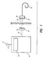
- FIG. 1shows the major elements of a known Implantable Cochlear Stimulation (ICS) system
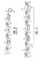
- FIG. 2depicts a functional flow for a prior-art amplitude mapping
- FIG. 3depicts a functional flow for envelope based amplitude mapping.
- FIG. 4depicts a flow chart for a CIS amplitude mapping application of the invention.
- FIG. 5depicts one embodiment of a flow chart for a CIS amplitude mapping application.
- FIG. 1A functional diagram of a typical Implantable Cochlear Stimulation (ICS) system is shown in FIG. 1 .
- the ICSincludes a speech processor 10 that could be a wearable speech processor, or a Behind-The-Ear (BTE) speech processor.
- a microphone 12may be connected to the speech processor 10 by a first wire 14 , or may be attached to the speech processor 10 as in the case of a BTE speech processor.
- the microphone 12converts acoustic energy into an electrical signal for subsequent processing.
- the speech processor 10contains a signal processor 16 that processes the electrical signal from the microphone 12 .
- the output signal of the signal processor 16is carried by a second wire 18 to a headpiece 20 carried on the patient's head.
- a first coil 22transmits the control signal 23 from the headpiece 20 to the implantable electronics 24 , which implantable electronics 24 includes a second coil 26 for receiving the control signal.
- the implantable electronics 24processes the control signal 23 to generate stimulation current for the electrode array 28 , which electrode array 28 is implanted in the patient's cochlea.
- the architecture of an ICS systemmay vary.
- the ICSmay include a wearable speech processor that is worn on the users belt and is connected to a microphone and headpiece by wiring, or a Behind-The-Ear (BTE) speech processor resembling a typical hearing aid, that is worn behind the patient's ear and retained by an earhook.
- BTEBehind-The-Ear
- Another exampleis a fully implantable ICS in which a speech processor 10 is integrated into the implantable electronics 26 .
- a microphoneor more generally a transducer
- a signal processorto provide a stimulation level. All of these variations benefit from the present invention as described below.
- the human earadjusts sound intensity with a logarithmic like scaling. Thus, if a sound is 10 times stronger, it may only be perceived to be twice as loud. ICS systems must perform a similar scaling, or mapping, if the patient is to perceive sounds with a natural intensity. Additionally, such logarithmic scaling has the advantage of providing intelligible hearing for low level sounds, without overwhelming the patient when loud sounds are encountered.
- FIG. 2A functional flow for a single channel of prior-art amplitude mapping is shown in FIG. 2 .
- the microphone 12provides an electrical signals to a bandpass filters 32 .
- the bandpass filter 32process the electrical signal 30 to generate a filtered signal 34 .
- the filtered signal 34is then processed by a mapper 36 which outputs the mapped signal 38 .
- the mapper 36maps the electrical signal 30 level measured by the microphone 12 into an electrical stimulation level to be provided to the electrode array 28 .
- the mapper 36is a log mapper, reflecting normal human hearing. Those skilled in the are will recognize that other mapping may produce similar results and those other mappings are withing the scope of the present invention.
- the mapped signal 38is processed by output processing 40 which outputs the stimulation signal 42 which is provided to the electrode array 28 .
- the log mapper 36operates on every signal processed by the amplitude mapping.
- FIG. 3A first embodiment of the present invention, depicted by one channel of an envelope based amplitude mapping applied to Simultaneous Analog Stimulation (SAS), is shown in FIG. 3 .
- SASSimultaneous Analog Stimulation
- the processing up to and including the bandpass filter 32is unchanged from known systems.
- the sample rate for the filtered signal 34is between 10 KHz and 25 KHz and is preferably 13 KHz or 17 KHz.
- Identical filtered signals 34 produced by the bandpass filter 32are carried on two paths.
- the top paths in FIG. 3represents the heart of the envelope based amplitude mapping.
- An envelope detector 44computes an envelop signal 46 from the filtered signal 34 .
- the envelope detector 44is a full wave rectifier followed by a lowpass filter with a cutoff of 100 Hz.
- the particular envelope detector 44 that is best for a specific ICS systemdepends on the details of processing that precedes the envelope detector 44 .
- Various other implementations of envelope detectorswill be apparent to those skilled in the art, and these variations are intended to fall within the scope of the present invention.
- the decimator 48creates a decimated signal 50 by reducing the sample rate by only passing every M th value of the envelope signal 46 .
- the sample rate of the decimated signal 50may be between 50 Hz and 1000 Hz and is 800 Hz in a preferred embodiment.
- the decimated sample rate in other embodiments of the inventionmay vary based on other parameters of ICS the present invention is exercised in, and on the preferences of the patient. While the envelope detector and decimator are shown as separate processing steps, in a preferred implementation, the lowpass filter and decimator are combined into a single Finite Impulse Response (FIR) filter.
- FIRFinite Impulse Response
- a log mapper 52computes a mapped signal 54 from the decimated signal 50 by taking a compressive transformation of the decimated signal 50 .
- the division by xis required due to the multiplying step described below.
- C1 and C2are based on psycho-acoustical phenomena and are patient dependent. Specifically, during a fitting process, measurements are made for each patient, and C1 and C2 are determined for the individual patient based on those measurements.
- the mapped signal 54may be viewed as a scaling factor related to the average level of the filtered signal 34 in the locality of the sample the scaling is applied to.
- a multiplier 56multiplies the mapped signal 54 times the original filtered signal 34 , to generate an envelope based amplitude mapping output signal 58 .
- the mapped signal 54 sample rate(hereafter the second sample rate) is lower than the filtered signal 34 sample rate (hereafter the first sample rate.) If the first sample rate is not substantially higher than the second sample rate, for example, the first sample rate is less than sixteen times the second sample rate, the mapped signal 54 may be used directly by the multiplier 56 . If the first sample rate is substantially higher than the second sample rate, for example, the first sample rate is more than sixteen times the second sample rate, the mapped signal 54 may be linearly interpolated to the first sample rate.
- the envelope based amplitude mapping described above for SAS amplitude mappingmay also be applied to Continuous Interleaved Sampler (CIS) amplitude mapping.
- a flow chart for a CIS amplitude mapping incorporating the present inventionis shown in FIG. 4 .
- the microphone 12 and bandpass filter 32are the same as in FIGS. 2 and 3 .
- the filtered signal 34is processed by a second envelope detector 60 to produce a second envelope signal 62
- the envelope signal 62is processed by a second decimator 64 , to generate a second decimated signal 66 .
- a preferred envelope detector 60comprises a full wave rectifier and a low pass filter.
- the lowpass filterhas a cut off frequency of about 800 Hz to 2000 Hz, preferably 800 Hz. While the envelope detector and decimator are shown as separate processing steps, in a preferred implementation, the lowpass filter and decimator are combined into a single Finite Impulse Response (FIR) filter.
- FIRFinite Impulse Response
- the decimated signal 66is processed by a third envelope detector 68 to obtain a third envelope signal 70
- the envelope signal 70is processed by a third decimator 72 to obtain a third decimated signal 74
- a preferred envelope detector 68comprises a full wave rectifier and a low pass filter.
- the lowpass filterhas a cut off frequency of about 40 Hz to 100 Hz, preferably 40 Hz. While the envelope detector and decimator are shown as separate processing steps, in a preferred implementation, the lowpass filter and decimator are combined into a single Finite Impulse Response (FIR) filter.
- FIRFinite Impulse Response
- the decimated signal 74is processed by the log mapper 52 to generate a second mapped signal 78 .
- the mapped signal 78 and the decimated signal 66are provided to the multiplier 80 , resulting in the second output signal 82 , which output signal 82 is provided to a pulse generator.
- One output signal 82is provided for each pulse in CIS processing.
- the decimated signal 66is at a higher data rate than the mapped signal 78 .
- the mapped signal 78is interpolated to the data rate of the decimated signal 66 in the multiplier 80 .
- a third embodiment comprising a second application of the present invention to CIS amplitude mappingis shown in FIG. 5 .
- the microphone 12 and bandpass filter 32are the same as in FIGS. 2 , 3 , and 4 .
- the filtered signal 34is processed by two parallel paths in the second CIS embodiment.
- a fourth envelope detector 84to produce a fourth envelope signal 86 , and the envelope signal 86 is processed by a fourth decimator 88 , to generate a fourth decimated signal 90 .
- a preferred envelope detector 84comprises a half wave rectifier and a low pass filter.
- the lowpass filterhas a cut off frequency of about 800 Hz to 2000 Hz, preferably 800 Hz. While the envelope detector and decimator are shown as separate processing steps, in a preferred implementation, the lowpass filter and decimator are combined into a single Finite Impulse Response (FIR) filter.
- FIRFinite Impulse Response
- the filtered signal 34is processed by a fifth envelope detector 92 to obtain a fifth envelope signal 94
- the envelope signal 94is processed by a fifth decimator 96 to obtain a fifth decimated signal 98 .
- a preferred envelope detector 92comprises a full wave rectifier and a low pass filter.
- the lowpass filterhas a cut off frequency of about 40 Hz to 100 Hz, preferably 40 Hz. While the envelope detector and decimator are shown as separate processing steps, in a preferred implementation, the lowpass filter and decimator are combined into a single Finite Impulse Response (FIR) filter.
- FIRFinite Impulse Response
- the decimated signal 98is processed by the log mapper 52 to generate a third mapped signal 102 .
- the mapped signal 102 and the decimated signal 90are provided to the multiplier 80 , resulting in a third output signal 104 , which output signal 104 is provided to a pulse generator.
- One output signal 104is provided for each pulse in CIS processing.
- the decimated signal 90is at a higher data rate than the mapped signal 102 .
- the mapped signal 102is interpolated to the data rate of the decimated signal 90 in the multiplier 80 .
- the log mapping functionis used to compress the stimulation current in a manner similar to the natural compression of the human ear.
- compressive mapping functionsproduce similar results, and fall within the scope of the present invention.
- the embodiment described aboveincludes a family of parallel band pass filters, but the use of a Fast Fourier Transformation (FFT) would produce similar results and is within the scope of the invention.
- FFTFast Fourier Transformation
Landscapes
- Health & Medical Sciences (AREA)
- Otolaryngology (AREA)
- Engineering & Computer Science (AREA)
- Biomedical Technology (AREA)
- Nuclear Medicine, Radiotherapy & Molecular Imaging (AREA)
- Radiology & Medical Imaging (AREA)
- Life Sciences & Earth Sciences (AREA)
- Animal Behavior & Ethology (AREA)
- General Health & Medical Sciences (AREA)
- Public Health (AREA)
- Veterinary Medicine (AREA)
- Prostheses (AREA)
Abstract
Description
Claims (4)
Priority Applications (2)
| Application Number | Priority Date | Filing Date | Title |
|---|---|---|---|
| US11/346,067US7542806B1 (en) | 2000-06-01 | 2006-02-02 | Envelope-based amplitude mapping for cochlear implant stimulus |
| US12/430,894US7937155B1 (en) | 2000-06-01 | 2009-04-28 | Envelope-based amplitude mapping for cochlear implant stimulus |
Applications Claiming Priority (4)
| Application Number | Priority Date | Filing Date | Title |
|---|---|---|---|
| US20862700P | 2000-06-01 | 2000-06-01 | |
| US09/866,096US6728578B1 (en) | 2000-06-01 | 2001-05-25 | Envelope-based amplitude mapping for cochlear implant stimulus |
| US10/684,863US6996438B1 (en) | 2000-06-01 | 2003-10-14 | Envelope-based amplitude mapping for cochlear implant stimulus |
| US11/346,067US7542806B1 (en) | 2000-06-01 | 2006-02-02 | Envelope-based amplitude mapping for cochlear implant stimulus |
Related Parent Applications (1)
| Application Number | Title | Priority Date | Filing Date |
|---|---|---|---|
| US10/684,863ContinuationUS6996438B1 (en) | 2000-06-01 | 2003-10-14 | Envelope-based amplitude mapping for cochlear implant stimulus |
Related Child Applications (1)
| Application Number | Title | Priority Date | Filing Date |
|---|---|---|---|
| US12/430,894DivisionUS7937155B1 (en) | 2000-06-01 | 2009-04-28 | Envelope-based amplitude mapping for cochlear implant stimulus |
Publications (1)
| Publication Number | Publication Date |
|---|---|
| US7542806B1true US7542806B1 (en) | 2009-06-02 |
Family
ID=32109760
Family Applications (4)
| Application Number | Title | Priority Date | Filing Date |
|---|---|---|---|
| US09/866,096Expired - LifetimeUS6728578B1 (en) | 2000-06-01 | 2001-05-25 | Envelope-based amplitude mapping for cochlear implant stimulus |
| US10/684,863Expired - Fee RelatedUS6996438B1 (en) | 2000-06-01 | 2003-10-14 | Envelope-based amplitude mapping for cochlear implant stimulus |
| US11/346,067Expired - Fee RelatedUS7542806B1 (en) | 2000-06-01 | 2006-02-02 | Envelope-based amplitude mapping for cochlear implant stimulus |
| US12/430,894Expired - Fee RelatedUS7937155B1 (en) | 2000-06-01 | 2009-04-28 | Envelope-based amplitude mapping for cochlear implant stimulus |
Family Applications Before (2)
| Application Number | Title | Priority Date | Filing Date |
|---|---|---|---|
| US09/866,096Expired - LifetimeUS6728578B1 (en) | 2000-06-01 | 2001-05-25 | Envelope-based amplitude mapping for cochlear implant stimulus |
| US10/684,863Expired - Fee RelatedUS6996438B1 (en) | 2000-06-01 | 2003-10-14 | Envelope-based amplitude mapping for cochlear implant stimulus |
Family Applications After (1)
| Application Number | Title | Priority Date | Filing Date |
|---|---|---|---|
| US12/430,894Expired - Fee RelatedUS7937155B1 (en) | 2000-06-01 | 2009-04-28 | Envelope-based amplitude mapping for cochlear implant stimulus |
Country Status (1)
| Country | Link |
|---|---|
| US (4) | US6728578B1 (en) |
Cited By (3)
| Publication number | Priority date | Publication date | Assignee | Title |
|---|---|---|---|---|
| US20090018614A1 (en)* | 2007-07-13 | 2009-01-15 | Med-El Elektromedizinische Geraete Gmbh | Electrical Nerve Stimulation with Broad Band Low Frequency Filter |
| US20090254150A1 (en)* | 2008-04-08 | 2009-10-08 | Med-El Elektromedizinische Geraete Gmbh | Electrical Stimulation of the Acoustic Nerve with Coherent Fine Structure |
| US8489194B2 (en) | 2011-02-14 | 2013-07-16 | Med-El Elektromedizinische Geraete Gmbh | Enhancing fine time structure transmission for hearing implant system |
Families Citing this family (40)
| Publication number | Priority date | Publication date | Assignee | Title |
|---|---|---|---|---|
| US6728578B1 (en)* | 2000-06-01 | 2004-04-27 | Advanced Bionics Corporation | Envelope-based amplitude mapping for cochlear implant stimulus |
| AUPQ952700A0 (en)* | 2000-08-21 | 2000-09-14 | University Of Melbourne, The | Sound-processing strategy for cochlear implants |
| US7130694B1 (en) | 2001-12-26 | 2006-10-31 | Advanced Bionics Corporation | Pulse skipping strategy |
| US20060100672A1 (en)* | 2004-11-05 | 2006-05-11 | Litvak Leonid M | Method and system of matching information from cochlear implants in two ears |
| US7522961B2 (en) | 2004-11-17 | 2009-04-21 | Advanced Bionics, Llc | Inner hair cell stimulation model for the use by an intra-cochlear implant |
| US7242985B1 (en)* | 2004-12-03 | 2007-07-10 | Advanced Bionics Corporation | Outer hair cell stimulation model for the use by an intra—cochlear implant |
| US7599500B1 (en) | 2004-12-09 | 2009-10-06 | Advanced Bionics, Llc | Processing signals representative of sound based on the identity of an input element |
| US7450994B1 (en)* | 2004-12-16 | 2008-11-11 | Advanced Bionics, Llc | Estimating flap thickness for cochlear implants |
| DE102005049507B4 (en)* | 2005-09-19 | 2007-10-25 | Fraunhofer-Gesellschaft zur Förderung der angewandten Forschung e.V. | Device for generating a combination signal and corresponding method and computer program for carrying out the method |
| US7779153B2 (en)* | 2005-10-27 | 2010-08-17 | Cochlear Limited | Automated collection of operational data from distributed medical devices |
| US8027733B1 (en) | 2005-10-28 | 2011-09-27 | Advanced Bionics, Llc | Optimizing pitch allocation in a cochlear stimulation system |
| US20100331913A1 (en)* | 2005-10-28 | 2010-12-30 | Mann Alfred E | Hybrid multi-function electrode array |
| JP2007128335A (en)* | 2005-11-04 | 2007-05-24 | Nec Corp | Replication arbitration device, method and program |
| US8265765B2 (en)* | 2005-12-08 | 2012-09-11 | Cochlear Limited | Multimodal auditory fitting |
| US7729775B1 (en) | 2006-03-21 | 2010-06-01 | Advanced Bionics, Llc | Spectral contrast enhancement in a cochlear implant speech processor |
| US8818517B2 (en)* | 2006-05-05 | 2014-08-26 | Advanced Bionics Ag | Information processing and storage in a cochlear stimulation system |
| US7925355B2 (en)* | 2006-07-17 | 2011-04-12 | Advanced Bionics, Llc | Systems and methods for determining a threshold current level required to evoke a stapedial muscle reflex |
| US8103354B2 (en)* | 2006-07-17 | 2012-01-24 | Advanced Bionics, Llc | Systems and methods for determining a threshold current level required to evoke a stapedial muscle reflex |
| US7995771B1 (en) | 2006-09-25 | 2011-08-09 | Advanced Bionics, Llc | Beamforming microphone system |
| US7864968B2 (en)* | 2006-09-25 | 2011-01-04 | Advanced Bionics, Llc | Auditory front end customization |
| US20090287277A1 (en)* | 2008-05-19 | 2009-11-19 | Otologics, Llc | Implantable neurostimulation electrode interface |
| US20100069997A1 (en)* | 2008-09-16 | 2010-03-18 | Otologics, Llc | Neurostimulation apparatus |
| US9044588B2 (en)* | 2009-04-16 | 2015-06-02 | Cochlear Limited | Reference electrode apparatus and method for neurostimulation implants |
| US20100318167A1 (en)* | 2009-04-17 | 2010-12-16 | Otologics, Llc | Neurostimulation electrode array and method of manufacture |
| US8771166B2 (en) | 2009-05-29 | 2014-07-08 | Cochlear Limited | Implantable auditory stimulation system and method with offset implanted microphones |
| US9656076B2 (en) | 2011-04-07 | 2017-05-23 | Nuvectra Corporation | Arbitrary waveform generator and neural stimulation application with scalable waveform feature and charge balancing |
| US8996117B2 (en)* | 2011-04-07 | 2015-03-31 | Greatbatch, Ltd. | Arbitrary waveform generator and neural stimulation application with scalable waveform feature |
| CN102579159B (en)* | 2012-02-23 | 2014-07-09 | 浙江诺尔康神经电子科技股份有限公司 | Electrical cochlea speech processor and processing method with signal compression in wide dynamic range |
| US9776001B2 (en) | 2015-06-11 | 2017-10-03 | Med-El Elektromedizinische Geraete Gmbh | Interaural coherence based cochlear stimulation using adapted envelope processing |
| US9770590B2 (en) | 2015-06-11 | 2017-09-26 | Med-El Elektromedizinische Geraete Gmbh | Switching hearing implant coding strategies |
| US9808624B2 (en) | 2015-06-11 | 2017-11-07 | Med-El Elektromedizinische Geraete Gmbh | Interaural coherence based cochlear stimulation using adapted fine structure processing |
| CN106558298A (en)* | 2015-09-29 | 2017-04-05 | 广州酷狗计算机科技有限公司 | A kind of audio analogy method and apparatus and system |
| US11071869B2 (en) | 2016-02-24 | 2021-07-27 | Cochlear Limited | Implantable device having removable portion |
| WO2018106572A1 (en)* | 2016-12-05 | 2018-06-14 | Med-El Elektromedizinische Geraete Gmbh | Interaural coherence based cochlear stimulation using adapted envelope processing |
| WO2020053726A1 (en)* | 2018-09-13 | 2020-03-19 | Cochlear Limited | Bilaterally-coordinated channel selection |
| US20240212672A1 (en)* | 2021-04-26 | 2024-06-27 | The Trustees Of Dartmouth College | Low power analog circuitry for artificial neural networks |
| US11660040B2 (en) | 2021-06-03 | 2023-05-30 | Moshe OFER | Methods and systems for displaying eye images to subjects and for interacting with virtual objects |
| JP2024525203A (en)* | 2021-06-28 | 2024-07-10 | オフェル,モシェ | Method and system for auditory nerve signal transformation - Patents.com |
| US11641555B2 (en)* | 2021-06-28 | 2023-05-02 | Moshe OFER | Methods and systems for auditory nerve signal conversion |
| US12223105B2 (en) | 2021-07-29 | 2025-02-11 | Moshe OFER | Methods and systems for controlling and interacting with objects based on non-sensory information rendering |
Citations (17)
| Publication number | Priority date | Publication date | Assignee | Title |
|---|---|---|---|---|
| US4284856A (en)* | 1979-09-24 | 1981-08-18 | Hochmair Ingeborg | Multi-frequency system and method for enhancing auditory stimulation and the like |
| US4536844A (en) | 1983-04-26 | 1985-08-20 | Fairchild Camera And Instrument Corporation | Method and apparatus for simulating aural response information |
| US4611598A (en)* | 1984-05-30 | 1986-09-16 | Hortmann Gmbh | Multi-frequency transmission system for implanted hearing aids |
| US5069210A (en)* | 1989-04-17 | 1991-12-03 | Jeutter Dean C | Cochlear implant employing frequency-division multiplexing and frequency modulation |
| US5271397A (en)* | 1989-09-08 | 1993-12-21 | Cochlear Pty. Ltd. | Multi-peak speech processor |
| US5323467A (en)* | 1992-01-21 | 1994-06-21 | U.S. Philips Corporation | Method and apparatus for sound enhancement with envelopes of multiband-passed signals feeding comb filters |
| US5749912A (en)* | 1994-10-24 | 1998-05-12 | House Ear Institute | Low-cost, four-channel cochlear implant |
| US5776172A (en) | 1989-09-22 | 1998-07-07 | Alfred E. Mann Foundation For Scientific Research | Multichannel implantable cochlear stimulator |
| US5824022A (en)* | 1996-03-07 | 1998-10-20 | Advanced Bionics Corporation | Cochlear stimulation system employing behind-the-ear speech processor with remote control |
| US5848171A (en)* | 1994-07-08 | 1998-12-08 | Sonix Technologies, Inc. | Hearing aid device incorporating signal processing techniques |
| US5983139A (en)* | 1997-05-01 | 1999-11-09 | Med-El Elektromedizinische Gerate Ges.M.B.H. | Cochlear implant system |
| WO2000018184A2 (en) | 1998-09-22 | 2000-03-30 | Goldstein Julius L | Hearing aids based on models of cochlear compression |
| US6064913A (en) | 1997-04-16 | 2000-05-16 | The University Of Melbourne | Multiple pulse stimulation |
| US6157861A (en)* | 1996-06-20 | 2000-12-05 | Advanced Bionics Corporation | Self-adjusting cochlear implant system and method for fitting same |
| WO2001019304A1 (en) | 1999-09-16 | 2001-03-22 | Advanced Bionics N.V. | Cochlear implant |
| US6219580B1 (en) | 1995-04-26 | 2001-04-17 | Advanced Bionics Corporation | Multichannel cochlear prosthesis with flexible control of stimulus waveforms |
| US6728578B1 (en)* | 2000-06-01 | 2004-04-27 | Advanced Bionics Corporation | Envelope-based amplitude mapping for cochlear implant stimulus |
- 2001
- 2001-05-25USUS09/866,096patent/US6728578B1/ennot_activeExpired - Lifetime
- 2003
- 2003-10-14USUS10/684,863patent/US6996438B1/ennot_activeExpired - Fee Related
- 2006
- 2006-02-02USUS11/346,067patent/US7542806B1/ennot_activeExpired - Fee Related
- 2009
- 2009-04-28USUS12/430,894patent/US7937155B1/ennot_activeExpired - Fee Related
Patent Citations (18)
| Publication number | Priority date | Publication date | Assignee | Title |
|---|---|---|---|---|
| US4284856A (en)* | 1979-09-24 | 1981-08-18 | Hochmair Ingeborg | Multi-frequency system and method for enhancing auditory stimulation and the like |
| US4536844A (en) | 1983-04-26 | 1985-08-20 | Fairchild Camera And Instrument Corporation | Method and apparatus for simulating aural response information |
| US4611598A (en)* | 1984-05-30 | 1986-09-16 | Hortmann Gmbh | Multi-frequency transmission system for implanted hearing aids |
| US5069210A (en)* | 1989-04-17 | 1991-12-03 | Jeutter Dean C | Cochlear implant employing frequency-division multiplexing and frequency modulation |
| US5271397A (en)* | 1989-09-08 | 1993-12-21 | Cochlear Pty. Ltd. | Multi-peak speech processor |
| US5776172A (en) | 1989-09-22 | 1998-07-07 | Alfred E. Mann Foundation For Scientific Research | Multichannel implantable cochlear stimulator |
| US5323467A (en)* | 1992-01-21 | 1994-06-21 | U.S. Philips Corporation | Method and apparatus for sound enhancement with envelopes of multiband-passed signals feeding comb filters |
| US5848171A (en)* | 1994-07-08 | 1998-12-08 | Sonix Technologies, Inc. | Hearing aid device incorporating signal processing techniques |
| US5749912A (en)* | 1994-10-24 | 1998-05-12 | House Ear Institute | Low-cost, four-channel cochlear implant |
| US6219580B1 (en) | 1995-04-26 | 2001-04-17 | Advanced Bionics Corporation | Multichannel cochlear prosthesis with flexible control of stimulus waveforms |
| US5824022A (en)* | 1996-03-07 | 1998-10-20 | Advanced Bionics Corporation | Cochlear stimulation system employing behind-the-ear speech processor with remote control |
| US6157861A (en)* | 1996-06-20 | 2000-12-05 | Advanced Bionics Corporation | Self-adjusting cochlear implant system and method for fitting same |
| US6064913A (en) | 1997-04-16 | 2000-05-16 | The University Of Melbourne | Multiple pulse stimulation |
| US5983139A (en)* | 1997-05-01 | 1999-11-09 | Med-El Elektromedizinische Gerate Ges.M.B.H. | Cochlear implant system |
| WO2000018184A2 (en) | 1998-09-22 | 2000-03-30 | Goldstein Julius L | Hearing aids based on models of cochlear compression |
| WO2001019304A1 (en) | 1999-09-16 | 2001-03-22 | Advanced Bionics N.V. | Cochlear implant |
| US6728578B1 (en)* | 2000-06-01 | 2004-04-27 | Advanced Bionics Corporation | Envelope-based amplitude mapping for cochlear implant stimulus |
| US6996438B1 (en)* | 2000-06-01 | 2006-02-07 | Advanced Bionics Corporation | Envelope-based amplitude mapping for cochlear implant stimulus |
Cited By (5)
| Publication number | Priority date | Publication date | Assignee | Title |
|---|---|---|---|---|
| US20090018614A1 (en)* | 2007-07-13 | 2009-01-15 | Med-El Elektromedizinische Geraete Gmbh | Electrical Nerve Stimulation with Broad Band Low Frequency Filter |
| US8639359B2 (en) | 2007-07-13 | 2014-01-28 | Med-El Elektromedizinische Geraete Gmbh | Electrical nerve stimulation with broad band low frequency filter |
| US8880194B2 (en) | 2007-07-13 | 2014-11-04 | Med-El Elektromedizinische Geraete Gmbh | Electrical nerve stimulation with broad band low frequency filter |
| US20090254150A1 (en)* | 2008-04-08 | 2009-10-08 | Med-El Elektromedizinische Geraete Gmbh | Electrical Stimulation of the Acoustic Nerve with Coherent Fine Structure |
| US8489194B2 (en) | 2011-02-14 | 2013-07-16 | Med-El Elektromedizinische Geraete Gmbh | Enhancing fine time structure transmission for hearing implant system |
Also Published As
| Publication number | Publication date |
|---|---|
| US6728578B1 (en) | 2004-04-27 |
| US7937155B1 (en) | 2011-05-03 |
| US6996438B1 (en) | 2006-02-07 |
Similar Documents
| Publication | Publication Date | Title |
|---|---|---|
| US7542806B1 (en) | Envelope-based amplitude mapping for cochlear implant stimulus | |
| US7697992B2 (en) | Systems for selecting one or more stimulation channels | |
| US8121698B2 (en) | Outer hair cell stimulation model for the use by an intra-cochlear implant | |
| EP2476267B1 (en) | Reducing an effect of ambient noise within an auditory prosthesis system | |
| US4532930A (en) | Cochlear implant system for an auditory prosthesis | |
| US8135152B2 (en) | Method and apparatus for envelope detection and enhancement of pitch cue of audio signals | |
| CN101743036B (en) | Electrical Nerve Stimulation with Broadband Low Frequency Filter | |
| JP5260614B2 (en) | Power efficient electrical stimulation | |
| US8527058B2 (en) | Methods and systems of automatically detecting an impedance of one or more electrodes in a cochlear implant system | |
| US7647118B1 (en) | Distributed compression amplitude mapping for a neural stimulation system | |
| EP2482923B1 (en) | Systems for representing different spectral components of an audio signal presented to a cochlear implant patient | |
| EP2943249B1 (en) | System for neural hearing stimulation | |
| US8706247B2 (en) | Remote audio processor module for auditory prosthesis systems | |
| McDermott et al. | A portable programmable digital sound processor for cochlear implant research | |
| US10357655B2 (en) | Frequency-dependent focusing systems and methods for use in a cochlear implant system | |
| US9446236B2 (en) | Systems and methods for optimizing a compliance voltage of an auditory prosthesis | |
| US20070239227A1 (en) | Frequency modulated stimulation strategy for cochlear implant system | |
| US9403005B2 (en) | Systems and methods for optimizing a compliance voltage of an auditory prosthesis | |
| Pandey et al. | A speech processor providing fricative and low-frequency periodicity information for single channel cochlear prosthesis | |
| Lin et al. | Development and application of programmable auditory stimulator |
Legal Events
| Date | Code | Title | Description |
|---|---|---|---|
| AS | Assignment | Owner name:BOSTON SCIENTIFIC NEUROMODULATION CORPORATION, CAL Free format text:CHANGE OF NAME;ASSIGNOR:ADVANCED BIONICS CORPORATION;REEL/FRAME:020296/0477 Effective date:20071116 Owner name:BOSTON SCIENTIFIC NEUROMODULATION CORPORATION, CALIFORNIA Free format text:CHANGE OF NAME;ASSIGNOR:ADVANCED BIONICS CORPORATION;REEL/FRAME:020296/0477 Effective date:20071116 Owner name:BOSTON SCIENTIFIC NEUROMODULATION CORPORATION,CALI Free format text:CHANGE OF NAME;ASSIGNOR:ADVANCED BIONICS CORPORATION;REEL/FRAME:020296/0477 Effective date:20071116 | |
| AS | Assignment | Owner name:ADVANCED BIONICS, LLC,CALIFORNIA Free format text:ASSIGNMENT OF ASSIGNORS INTEREST;ASSIGNOR:BOSTON SCIENTIFIC NEUROMODULATION CORPORATION;REEL/FRAME:020340/0713 Effective date:20080107 Owner name:ADVANCED BIONICS, LLC, CALIFORNIA Free format text:ASSIGNMENT OF ASSIGNORS INTEREST;ASSIGNOR:BOSTON SCIENTIFIC NEUROMODULATION CORPORATION;REEL/FRAME:020340/0713 Effective date:20080107 | |
| FPAY | Fee payment | Year of fee payment:4 | |
| REMI | Maintenance fee reminder mailed | ||
| LAPS | Lapse for failure to pay maintenance fees | ||
| STCH | Information on status: patent discontinuation | Free format text:PATENT EXPIRED DUE TO NONPAYMENT OF MAINTENANCE FEES UNDER 37 CFR 1.362 | |
| FP | Lapsed due to failure to pay maintenance fee | Effective date:20170602 | |
| AS | Assignment | Owner name:ADVANCED BIONICS AG, SWITZERLAND Free format text:ASSIGNMENT OF ASSIGNORS INTEREST;ASSIGNOR:ADVANCED BIONICS, LLC;REEL/FRAME:050806/0005 Effective date:20111130 |