US7542452B2 - Systems and methods for implementing an enhanced multi-channel direct link protocol between stations in a wireless LAN environment - Google Patents
Systems and methods for implementing an enhanced multi-channel direct link protocol between stations in a wireless LAN environmentDownload PDFInfo
- Publication number
- US7542452B2 US7542452B2US10/821,420US82142004AUS7542452B2US 7542452 B2US7542452 B2US 7542452B2US 82142004 AUS82142004 AUS 82142004AUS 7542452 B2US7542452 B2US 7542452B2
- Authority
- US
- United States
- Prior art keywords
- wireless station
- infrastructure
- direct link
- frequency channel
- service set
- Prior art date
- Legal status (The legal status is an assumption and is not a legal conclusion. Google has not performed a legal analysis and makes no representation as to the accuracy of the status listed.)
- Expired - Fee Related, expires
Links
- 238000000034methodMethods0.000titleclaimsabstractdescription100
- 238000004891communicationMethods0.000claimsdescription21
- 230000005540biological transmissionEffects0.000abstractdescription11
- 238000010586diagramMethods0.000description16
- 230000004044responseEffects0.000description7
- 238000005516engineering processMethods0.000description6
- 230000000977initiatory effectEffects0.000description4
- 230000003993interactionEffects0.000description3
- 230000006855networkingEffects0.000description3
- 238000012546transferMethods0.000description3
- 238000013459approachMethods0.000description2
- 230000015572biosynthetic processEffects0.000description2
- 238000013461designMethods0.000description2
- 230000003287optical effectEffects0.000description2
- 239000002245particleSubstances0.000description2
- 101100172132Mus musculus Eif3a geneProteins0.000description1
- 230000001174ascending effectEffects0.000description1
- VYLDEYYOISNGST-UHFFFAOYSA-Nbissulfosuccinimidyl suberateChemical compoundO=C1C(S(=O)(=O)O)CC(=O)N1OC(=O)CCCCCCC(=O)ON1C(=O)C(S(O)(=O)=O)CC1=OVYLDEYYOISNGST-UHFFFAOYSA-N0.000description1
- 239000000872bufferSubstances0.000description1
- 230000001413cellular effectEffects0.000description1
- 238000006243chemical reactionMethods0.000description1
- 230000004069differentiationEffects0.000description1
- 238000005401electroluminescenceMethods0.000description1
- 230000006870functionEffects0.000description1
- 230000002452interceptive effectEffects0.000description1
- 239000004973liquid crystal related substanceSubstances0.000description1
- 230000005055memory storageEffects0.000description1
- 238000012986modificationMethods0.000description1
- 230000004048modificationEffects0.000description1
- 238000012545processingMethods0.000description1
- 230000011664signalingEffects0.000description1
Images


Classifications
- H—ELECTRICITY
- H04—ELECTRIC COMMUNICATION TECHNIQUE
- H04W—WIRELESS COMMUNICATION NETWORKS
- H04W76/00—Connection management
- H04W76/10—Connection setup
- H04W76/14—Direct-mode setup
- H—ELECTRICITY
- H04—ELECTRIC COMMUNICATION TECHNIQUE
- H04W—WIRELESS COMMUNICATION NETWORKS
- H04W84/00—Network topologies
- H04W84/02—Hierarchically pre-organised networks, e.g. paging networks, cellular networks, WLAN [Wireless Local Area Network] or WLL [Wireless Local Loop]
- H04W84/10—Small scale networks; Flat hierarchical networks
- H04W84/12—WLAN [Wireless Local Area Networks]
- H—ELECTRICITY
- H04—ELECTRIC COMMUNICATION TECHNIQUE
- H04W—WIRELESS COMMUNICATION NETWORKS
- H04W88/00—Devices specially adapted for wireless communication networks, e.g. terminals, base stations or access point devices
- H04W88/08—Access point devices
- H—ELECTRICITY
- H04—ELECTRIC COMMUNICATION TECHNIQUE
- H04W—WIRELESS COMMUNICATION NETWORKS
- H04W92/00—Interfaces specially adapted for wireless communication networks
- H04W92/16—Interfaces between hierarchically similar devices
- H04W92/18—Interfaces between hierarchically similar devices between terminal devices
Definitions
- the present inventionrelates generally to wireless networking. More specifically, the present invention relates to systems and methods for implementing an enhanced multi-channel direct link protocol between wireless stations in a wireless LAN environment.
- Computer and communication technologiescontinue to advance at a rapid pace. Indeed, computer and communication technologies are involved in many aspects of a person's day. For example, many devices being used today have a small computer inside of the device. These small computers come in varying sizes and degrees of sophistication. Computers commonly used include everything from hand-held computing devices to large multi-processor computer systems.
- Computersare used in almost all aspects of business, industry and academic endeavors. More and more homes are using computers as well. The pervasiveness of computers has been accelerated by the increased use of computer networks, including the Internet. Most companies have one or more computer networks and also make extensive use of the Internet. The productivity of employees often requires human and computer interaction. Improvements in computers and software have been a force for bringing about great increases in business and industrial productivity.
- a computer networkmay be organized as a stack of layers. The purpose of each layer is to offer certain services to the higher layers.
- layer N on one computing devicecommunicates with layer N on another computing device.
- the rules and conventions used in this communicationare collectively known as the layer N protocol.
- each layerpasses data and control information to the layer immediately below it, until the lowest layer is reached.
- the lowest layergenerally includes the physical medium through which the data is actually transferred.
- OSIOpen Systems Interconnection
- the OSI modelincludes seven layers. In ascending order, these layers include the physical layer, the data link layer, the network layer, the transport layer, the session layer, the presentation layer, and the application layer.
- the protocols used to determine who goes next on a multiaccess channelbelong to a sublayer of the data link layer called the Medium Access Control (MAC) sublayer.
- the MAC sublayeris important in many local area networks (LANs), many of which use a multiaccess channel as the basis for communication.
- a wireless LANis a system in which every device (often called a wireless station) has a radio modem and an antenna with which it can communicate with other devices and/or systems.
- Wireless LANsare becoming increasingly common in homes, office buildings, public places such as airports and coffee shops, and other places.
- IEEE 802.11There is a standard for wireless LANs, called IEEE 802.11, which many systems implement and which is becoming very widespread. Benefits may be realized by improved systems and methods that facilitate wireless networking of electronic devices in a more efficient and cost-effective manner.
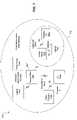
- FIG. 1is a block diagram illustrating an exemplary system in which some embodiments may be practiced
- FIG. 2is a flow diagram illustrating an embodiment of a method which may be performed by the first wireless station and the second wireless station in the infrastructure basic service set network shown in FIG. 1 ;
- FIG. 3is a flow diagram illustrating an exemplary method used by the AP and the wireless stations for determining the direct link frequency channel;
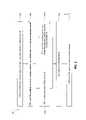
- FIG. 4is a flow diagram illustrating an embodiment of a method that may be performed by the wireless stations while they are involved in a direct link in accordance with the enhanced direct link protocol;
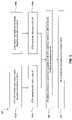
- FIG. 5is a flow diagram illustrating another embodiment of a method that may be performed by the wireless stations while initiating a direct link in accordance with the enhanced direct link protocol;
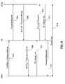
- FIG. 6is a signal flow diagram illustrating the interaction between the components in the infrastructure basic service set network in accordance with an embodiment of the enhanced direct link protocol
- FIG. 7is a block diagram illustrating another exemplary system in which some embodiments may be practiced.
- FIG. 8is a block diagram illustrating the major hardware components typically utilized in a wireless station.
- a computer-readable medium for storing program data that comprises executable instructions for implementing a method in a first wireless stationis disclosed.
- the first wireless stationis part of an infrastructure basic service set network.
- the infrastructure basic service set networkalso comprises an access point and a second wireless station.
- the wireless stations of the infrastructure basic service set networkcommunicate on an infrastructure frequency channel.
- the methodcomprises determining that at least one condition is satisfied for establishing a direct link with the second wireless station for transmission of data from the first wireless station to the second wireless station.
- the methodalso comprises establishing the direct link with the second wireless station on a direct link frequency channel that is different than the infrastructure frequency channel.
- the methodalso comprises transmitting the data to the second wireless station via the direct link.
- the methodfurther comprises terminating the direct link and rejoining the infrastructure basic service set network.
- the methodfurther comprises periodically tuning to the infrastructure frequency channel to receive every nth beacon from the access point. If a beacon is received that comprises a notification about downlink data for the first wireless station that is buffered at the access point, the method may also comprise determining whether a condition is satisfied for terminating the direct link. If the condition is satisfied, the method may also comprise terminating the direct link and rejoining the infrastructure basic service set network. If the condition is not satisfied, the method may also comprise tuning to the infrastructure frequency channel at scheduled time intervals to receive the downlink data from the access point.
- the methodmay comprise periodically tuning to the infrastructure frequency channel to receive every nth beacon. If the first wireless station does not see any buffered downlink data advertised in the beacons, the value of n may be increased.
- the methodmay also comprise obtaining unused frequency channels information about unused frequency channels near the first wireless station.
- the unused frequency channels informationmay be sent to the access point.
- the chosen direct link frequency channelmay be received from the access point.
- determining that the at least one condition is satisfied for establishing the direct linkcomprises determining that the number of consecutive frames that have been generated at the first wireless station and that have a same destination address exceeds a threshold value, and determining that the destination address is in the same infrastructure basic service set network.
- a computer-readable medium for storing program data that comprises executable instructions for implementing a method in a second wireless stationis also disclosed.
- the second wireless stationis part of an infrastructure basic service set network.
- the infrastructure basic service set networkalso comprises a first wireless station and an access point.
- the wireless stations of the infrastructure basic service set networkcommunicate on an infrastructure frequency channel.
- the methodcomprises determining that at least one condition is satisfied for establishing a direct link with the first wireless station for transmission of data from the first wireless station to the second wireless station.
- the methodalso comprises establishing the direct link with the first wireless station on a direct link frequency channel that is different than the infrastructure frequency channel.
- the methodalso comprises receiving the data from the first wireless station via the direct link.
- determining that the at least one condition is satisfied for establishing the direct linkcomprises determining that the number of consecutive frames that have been received at the second wireless station and that have a same source address exceeds a threshold value, and also determining that the source address is in the infrastructure basic service set network.
- a computer-readable medium for storing program data that comprises executable instructions for implementing a method in an access pointis also disclosed.
- the access pointis part of an infrastructure basic service set network.
- the infrastructure basic service set networkalso comprises a first wireless station and a second wireless station.
- the wireless stations of the infrastructure basic service set networkcommunicate on an infrastructure frequency channel.
- the methodcomprises receiving first unused frequency channels information about first unused frequency channels near the first wireless station.
- the methodalso comprises receiving second unused frequency channels information about second unused frequency channels near the second wireless station.
- the methodalso comprises using the first unused frequency channels information and the second unused frequency channels information to select a selected frequency channel that is available to both the first wireless station and the second wireless station and that is different than the infrastructure frequency channel and any other direct link channels in the basic service set.
- the methodalso comprises transmitting the selected frequency channel to the first wireless station.
- a method in a first wireless station that is part of an infrastructure basic service set networkis also disclosed.
- the infrastructure basic service set networkalso comprises an access point and a second wireless station.
- the wireless stations of the infrastructure basic service set networkcommunicate on an infrastructure frequency channel.
- the methodcomprises determining that at least one condition is satisfied for establishing a direct link with the second wireless station for transmission of data from the first wireless station to the second wireless station.
- the methodalso comprises establishing the direct link with the second wireless station on a direct link frequency channel that is different than the infrastructure frequency channel.
- the methodalso comprises transmitting the data to the second wireless station via the direct link.
- a method in a second wireless station that is part of an infrastructure basic service set networkis also disclosed.
- the infrastructure basic service set networkalso comprises a first wireless station and an access point.
- the wireless stations of the infrastructure basic service set networkcommunicate on an infrastructure frequency channel.
- the methodcomprises determining that at least one condition is satisfied for establishing a direct link with the first wireless station for transmission of data from the first wireless station to the second wireless station.
- the methodalso comprises establishing the direct link with the first wireless station on a direct link frequency channel that is different than the infrastructure frequency channel and any other direct link channels already existing in the basic service set.
- the methodalso comprises receiving the data from the first wireless station via the direct link.
- a method in an access point that is part of an infrastructure basic service set networkis also disclosed.
- the infrastructure basic service set networkalso comprises a first wireless station and a second wireless station.
- the wireless stations of the infrastructure basic service set networkcommunicate on an infrastructure frequency channel.
- the methodcomprises receiving first unused frequency channels information about first unused frequency channels near the first wireless station.
- the methodalso comprises receiving second unused frequency channels information about second unused frequency channels near the second wireless station.
- the methodalso comprises using the first unused frequency channels information and the second unused frequency channels information to select a selected frequency channel that is available to both the first wireless station and the second wireless station and that is different than the infrastructure frequency channel.
- the methodalso comprises transmitting the selected frequency channel to the first wireless station.
- a first wireless stationthat is configured to be part of an infrastructure basic service set network.
- the infrastructure basic service set networkalso comprises an access point and a second wireless station.
- the wireless stations of the infrastructure basic service set networkcommunicate on an infrastructure frequency channel.
- the first wireless stationcomprises a processor and memory in electronic communication with the processor. Instructions are stored in the memory.
- the instructionsare executable to implement a method that comprises determining that at least one condition is satisfied for establishing a direct link with the second wireless station for transmission of data from the first wireless station to the second wireless station.
- the methodalso comprises establishing the direct link with the second wireless station on a direct link frequency channel that is different than the infrastructure frequency channel.
- the methodalso comprises transmitting the data to the second wireless station via the direct link.
- a first wireless station that is configured to be part of an infrastructure basic service set networkis also disclosed.
- the infrastructure basic service set networkalso comprises a first wireless station and an access point.
- the wireless stations of the infrastructure basic service set networkcommunicate on an infrastructure frequency channel.
- the second wireless stationcomprises a processor and memory in electronic communication with the processor. Instructions are stored in the memory.
- the instructionsare executable to implement a method that comprises determining that at least one condition is satisfied for establishing a direct link with the first wireless station for transmission of data from the first wireless station to the second wireless station.
- the methodalso comprises establishing the direct link with the first wireless station on a direct link frequency channel that is different than the infrastructure frequency channel.
- the methodalso comprises receiving the data from the first wireless station via the direct link.
- An access point that is configured to be part of an infrastructure basic service set networkis also disclosed.
- the infrastructure basic service set networkalso comprises a first wireless station and a second wireless station.
- the wireless stations of the infrastructure basic service set networkcommunicate on an infrastructure frequency channel.
- the access pointcomprises a processor and memory in electronic communication with the processor. Instructions are stored in the memory. The instructions are executable to implement a method that comprises receiving first unused frequency channels information about first unused frequency channels near the first wireless station.
- the methodalso comprises receiving second unused frequency channels information about second unused frequency channels near the second wireless station.
- the methodalso comprises using the first unused frequency channels information and the second unused frequency channels information to select a selected frequency channel that is available to both the first wireless station and the second wireless station and that is different than the infrastructure frequency channel and any other direct link channels already existing in the basic service set.
- the methodalso comprises transmitting the selected frequency channel to the first wireless station.
- a software module or componentmay include any type of computer instruction or computer executable code located within a memory device and/or transmitted as electronic signals over a system bus or network.
- a software modulemay, for instance, comprise one or more physical or logical blocks of computer instructions, which may be organized as a routine, program, object, component, data structure, etc., that performs one or more tasks or implements particular abstract data types.
- a particular software modulemay comprise disparate instructions stored in different locations of a memory device, which together implement the described functionality of the module.
- a modulemay comprise a single instruction, or many instructions, and may be distributed over several different code segments, among different programs, and across several memory devices.
- Some embodimentsmay be practiced in a distributed computing environment where tasks are performed by a remote processing device linked through a communications network.
- software modulesmay be located in local and/or remote memory storage devices.
- FIG. 1is a block diagram illustrating an exemplary system 100 in which some embodiments may be practiced.
- the system 100includes an infrastructure basic service set (BSS) network 102 .
- the infrastructure BSS network 102includes a plurality of wireless stations (STA) 104 .
- STAwireless stations
- a STA 104is any electronic device that is capable of wireless communication.
- a STA 104may either be mobile or stationary. Examples of some STAs 104 that may be used with embodiments disclosed herein include personal computers (PCs), laptops, personal digital assistants (PDAs), cellular phones, digital video cameras, wireless televisions (TVs), and so forth.
- PCspersonal computers
- PDAspersonal digital assistants
- TVswireless televisions
- the infrastructure BSS network 102also includes an access point (AP) 106 .
- the AP 106is a wireless station that provides access to a distribution system (DS) (not shown).
- the DSis the architectural component used to interconnect the infrastructure BSS network 102 to other networks (e.g., the Internet, other infrastructure BSS networks, etc.).
- the STAs 104 in the infrastructure BSS network 102are in wireless communication with the AP 106 .
- the STAs 104 and the AP 106communicate with one another on a particular frequency channel, which will be referred to herein as the infrastructure frequency channel. Additional characteristics of the infrastructure BSS network 102 , the STAs 104 and the AP 106 are discussed in greater detail in “IEEE Wireless LAN Edition,” September 2003, which is hereby incorporated by reference in its entirety.
- one STA 104 within the infrastructure BSS network 102has data 108 to transmit to another STA 104 within the same infrastructure BSS network 102 .
- a typical exampleis a home network in which multiple electronic devices (TVs, PCs, cameras, etc.) are trying to communicate with each other wirelessly.
- the STA 104 that has the data 108 to transmitwill sometimes be referred to herein as the first STA 104 a or the source STA 104 a
- the STA 104 that receives the data 108will sometimes be referred to herein as the second STA 104 b or the destination STA 104 b .
- Access to the infrastructure frequency channelis handled by the Medium Access Control (MAC) sublayer on each of the STAs 104 within the network 102 .
- MACMedium Access Control
- the MACis implemented such that the first STA 104 a sends the data 108 to the AP 106 , and the AP 106 forwards the data 108 to the second STA 104 b .
- Thisis the approach taken in the IEEE 802.11 standard. While this approach is good for stations trying to communicate with the external network, it's not a very good solution for BSSs having many devices trying to communicate with each other within the BSS itself.
- the 802.11 MACis CSMA based and hence with the increase in the number of wireless clients, the signaling and the contention overhead may increase so that the aggregate throughput may not satisfy the need of multiple high bandwidth delay sensitive wireless links.
- the 802.11 MACmay not be able to handle the load and hence may lead to poor signal quality.
- the recently introduced IEEE 802.11e MACcan provide good service differentiation and hence can provide quality of service (QoS) for the different kinds of services in a typical wireless networking scenario.
- QoSquality of service
- Direct Link Protocolhas been proposed in the IEEE 802.11e draft to address the issue of efficient communication between wireless stations 104 in the same BSS network 102 .
- the DLPallows any two STAs 104 to exchange capability information through the AP 106 and establish a direct link (DL) between them in order to transfer data 108 directly.
- the DLPis defined in such a way that the AP 106 (or the centralized controller) is engaged during any direct link conversion, so that any other STAs 104 in the infrastructure BSS network 102 are not able to talk to the AP 106 or to instantiate DLs to other STAs 104 in the infrastructure BSS network 102 through the AP 106 .
- the DLPis designed in such a way that, though the STAs 104 are communicating directly, they are still a part of the infrastructure network controlled by the AP 106 . Please refer to the 802.11e D6.0 document for additional information.
- Embodiments disclosed hereinrelate to various embodiments of an enhanced multi-channel DLP 110 which may be implemented on the STAs 104 and the AP 106 within the infrastructure BSS network 102 .
- the enhanced DLP 110may be implemented as part of the MAC sublayer.
- STAs 104 within the same infrastructure BSS network 102may be configured to trigger the formation of multiple small temporary adhoc groups using different frequency channels. This may increase the throughput in many situations, as will be described in greater detail below.
- FIG. 2is a flow diagram illustrating an embodiment of a method 200 which may be performed by the first STA 104 a and the second STA 104 b in the infrastructure BSS network 102 shown in FIG. 1 .
- the method 200is performed when the first STA 104 a has a substantial amount of data 108 for transmission to the second STA 104 b .
- a digital video camera and a PCmay perform the method 200 when the digital video camera has video data for streaming to the PC.
- the first STA 104 a and the second STA 104 bdetermine 202 that certain conditions have been satisfied for establishing a DL. Some exemplary conditions will be described below.
- the DLis then established 204 on a frequency channel that is different than the infrastructure frequency channel. This frequency channel will be referred to herein as the DL frequency channel.
- the STAs 104After the DL is formed the STAs 104 temporarily disconnect from the infrastructure BSS network 102 and start communicating on the DL frequency channel.
- the first STA 104 atransmits 206 a the data 108 to the second STA 104 b via the DL. Accordingly, a type of temporary adhoc network is formed which does not interfere with the other similar DLs and the infrastructure BSS network 102 itself. Thus, the other STAs 104 in the infrastructure BSS network 102 can continue accessing the AP 106 .
- the AP 106When the first STA 104 a and the second STA 104 b are involved in the DL, the AP 106 records them as being in a virtual sleep mode. If the AP 106 receives downlink data which is destined for either the first STA 104 a or the second STA 104 b , the AP 106 buffers the downlink data and broadcasts a notification about the buffered downlink data in the beacon. Therefore, in some embodiments, the first STA 104 a and the second STA 104 b periodically tune 206 b to the infrastructure frequency channel to receive beacons from the AP 106 .
- the DLis terminated 208 .
- thisinvolves the first STA 104 a and the second STA 104 b exchanging standard DL teardown request and response frames (as described in the Direct Link Protocol Specification referenced above).
- the first STA 104 a and the second STA 104 bthen rejoin 210 the infrastructure BSS network 102 . This may involve the first and second STAs 104 a , 104 b tuning to the infrastructure frequency channel and informing the AP 106 about the termination of the DL.
- the AP 106treats them like any other infrastructure client and polls them when needed.
- Either of the STAs 104 involved in a DLmay terminate the DL before transmission of the data 108 is finished.
- the higher layers of one (or both) of the STAs 104 in a DLmay sense high frame loss or jitter. If this occurs, the DL may be terminated and the STAs may rejoin the infrastructure BSS network 102 .
- a DLhas been described as involving only two STAs 104 . However, more than two STAs 104 may be involved in a DL. As indicated previously, the STAs 104 involved in a DL may be referred to as a temporary adhoc group.
- the new STA 104can join the adhoc group by gathering information about the adhoc group from the AP 106 and by tuning into the frequency of the adhoc network (i.e., the DL frequency). The new STA 104 may follow the same DL initiation protocol as the other STAs 104 in the adhoc group.
- Multiple temporary adhoc groups, each on a different frequency channelcan exist in the same infrastructure BSS network 102 .
- TXOPsEDCA transmission opportunities
- IBSSindependent basic service set
- the step of determining 202 that certain conditions have been satisfied for establishing a DLmay be performed at least partially by the service access point (SAP) of the media access control (MAC) layers of the first STA 104 a and the second STA 104 b .
- SAPservice access point
- MACmedia access control
- the higher layers of the first STA 104 a and the second STA 104 bmay also assist in performing this step.
- the MAC SAP of the source STA 104 amaintains a counter that counts the number of consecutive MAC service data units (MSDUs) generated at the STA 104 having the same destination address. If this counter exceeds a predetermined threshold value and if the destination address is in the same infrastructure BSS network 102 , the MAC SAP of the STA 104 realizes a potential possibility of a DL and sends a DL request to the destination address.
- MSDUsMAC service data units
- the MAC SAP of the destination STA 104 balso maintains a counter that counts the number of consecutive MSDUs received at the STA 104 having the same source address.
- the destination STA 104 breceives a DL request from the source STA 104 a , the request is accepted if this counter exceeds a threshold value.
- the destination STA 104 bdetermines that it also has data traffic from STAs 104 other than the source STA 104 a requesting for a DL connection, it typically rejects the DL connection.
- the STAs 104can also exchange their respective transmit power information in the DL requests and responses. In this way, both the STAs 104 can establish a DL with the minimum amount of transmit power required to reach each other and the AP 106 during the time in which they listen for the beacons on the infrastructure frequency channel.
- the higher layers within an STA 104may initiate formation of a DL when they determine that a particular application running on the STA 104 demands a larger share of the channel than the one presently affordable by the infrastructure BSS network 102 . This may be decided based on the amount of jitter and frame loss that the application is facing.
- the AP 106may take an active role in determining the frequency channel for a DL between two (or more) STAs 104 .
- FIG. 3is a flow diagram illustrating an exemplary method 300 for determining the DL frequency channel.
- the first STA 104 aobtains 302 a information about unused frequency channels in its vicinity and sends 304 a that information to the AP 106 .
- the second STA 104 bobtains 302 a information about unused frequency channels in its vicinity and sends 304 b that information to the AP 106 .
- the AP 106uses the information that it receives from the first STA 104 a and the second STA 104 b to select 306 a frequency channel for the DL that is available to both the first STA 104 a and the second STA 104 b .
- the DL frequency channelis different than the infrastructure frequency channel and is also different than the frequency channels used in any other DLs in the infrastructure BSS network 102 .
- the AP 106then transmits 308 the selected frequency channel to the first STA 104 a.
- the step of obtaining 302 information about unused frequency channelsmay be performed, at least in part, by the network interface card (NIC) of an STA 104 .
- the NIC of an STA 104may be configured to periodically scan certain frequency channels to determine the available frequency channels in its vicinity.
- the NIC of an STA 104may be configured to scan some or all of the standard channels in the unlicensed frequency bands, such as the 5 GHz and/or 2.4 GHz bands.
- the information about the unused frequency channelsmay be stored in a variety of different forms, such as a bitmap field.
- FIG. 4is a flow diagram illustrating an embodiment of a method 400 that may be performed by an STA 104 while it is involved in a DL in accordance with the enhanced DLP 110 .
- an STA 104While an STA 104 is involved in a DL, it periodically tunes to the infrastructure frequency channel to receive beacons from the AP 106 .
- the STA 104tunes 402 to the infrastructure frequency channel to receive every nth beacon.
- the STA 104determines 404 whether the beacon includes a notification about downlink data that is buffered at the AP 106 . If there is buffered data, the STA 104 determines 406 whether a condition is satisfied for terminating the DL. In the illustrated embodiment, the STA 104 sets a counter to count the number of beacons from the AP 106 in which it finds a notification about buffered downlink data at the AP 106 . If this counter crosses a threshold, the condition for terminating the DL is satisfied.
- the DLis terminated 408 and the STA 104 rejoins the infrastructure BSS network 102 .
- the STA 104may then receive the downlink data via the infrastructure BSS network 102 .
- the DLis not terminated, and the STA 104 tunes 410 to the infrastructure frequency channel at scheduled time intervals to receive the buffered downlink data from the AP 106 . In typical embodiments, this may involve sending a request to the AP 106 to poll it during a contention free period (CFP) in order to send the buffered downlink data.
- CCPcontention free period
- the STA 104determines 412 whether a condition is satisfied for increasing the waiting period, i.e., the period of time that the STA 104 waits before tuning to the infrastructure frequency channel to receive another beacon. As indicated previously, the STAs 104 need not listen to all the beacons transmitted by the AP 106 but may choose to listen to every nth beacon, the value of n being decided by the STAs 104 based on certain heuristics which can be considered a design issue.
- the STAs 104do not see any buffered downlink data advertised in the beacons every time they are switching to the infrastructure channel, they increase the value of n (so that they switch to the infrastructure channel less often) and continue to do so until they come to know of any downlink data buffered at the AP 106 .
- the STA 104increases 414 the value of n and tunes back into the DL frequency channel. Otherwise, the STA 104 does not increase 416 the value of n.
- FIG. 5is a flow diagram illustrating an embodiment of a method 500 that may be performed by a source STA 104 a and a destination STA 104 b in accordance with the enhanced DLP 110 .
- the MAC SAP of the source STA 104 asets 502 a counter (n) for consecutive frames generated at the source STA 104 a that have the same destination MAC address.
- the MAC SAP of the destination STA 104 bsets 504 a counter (m) for the number of consecutive frames received at the destination STA 104 b that have the same source MAC address.
- the source STA 104 adetermines 506 that the counter (n) exceeds a threshold and that the destination address is in the same BSS network 102
- the destination STA 104 bdetermines 508 that the counter (m) exceeds a threshold and that the source address is in the same BSS network 102
- the source STA 104 a and the destination STA 104 bcheck 510 for a free channel in the vicinity.
- the source STA 104 a and the destination STA 104 bnegotiate with the AP 106 for a common channel which is free for the source STA 104 a , the destination STA 104 b and the AP 106 .
- the source STA 104 a and the destination STA 104 bexchange 514 a DL initiation handshake through the AP 106 .
- the source STA 104 a and the destination STA 104 bthen tune 516 onto the DL frequency channel and establish the DL. If a free channel is not found 512 , the source STA 104 a and the destination STA 104 b do not establish 518 a DL, and the source STA 104 a uses the infrastructure network to transmit the data 108 to the destination STA 104 b.
- step 506the source STA 104 a determines 506 that the counter (n) does not exceed a threshold or that the destination address is not in the same BSS network 102 , then the source STA 104 a does not initiate 520 a DL request with the destination STA 104 b . Instead, the source STA 104 a uses the infrastructure frequency channel to transmit the data 108 to the destination STA 104 b . If in step 508 the destination STA 104 b determines 508 that the counter (m) does not exceed a threshold or that the source address is not in the same BSS network 102 , then the destination STA 104 b rejects 522 the DL if requested by the source STA 104 a.
- FIG. 6is a signal flow diagram illustrating the interaction between the components in the infrastructure BSS network 102 in accordance with an embodiment of the enhanced DLP 110 .
- the first STA 104 adetermines that certain conditions have been satisfied for establishing a DL with the second STA 104 b
- the first STA 104 asends a message 602 to the AP 106 .
- the message 602includes a DL request, which includes all the capability information in a standard DL request (as described in the Direct Link Protocol Specification referenced above).
- the message 602also includes information about the unused frequency channels in its vicinity. This information can be conveyed in the form of a channel bitmap.
- the AP 106forwards the DL request to the second STA 104 b . More specifically, the AP 106 sends a message 604 to the second STA 104 b .
- the message 604includes the DL request.
- the second STA 104 bdetermines whether certain conditions have been satisfied for establishing a DL with the first STA 104 a . If the second STA 104 b determines that the conditions for establishing a DL have been satisfied, the second STA 104 b sends a message 606 to the AP 106 .
- the message 606includes a DL response.
- the DL responseincludes all the fields in a standard DL response (as described in the Direct Link Protocol Specification referenced above).
- the message 606also includes information about the unused frequency channels in the vicinity of the second STA 104 b .
- the second STA 104 bIf the second STA 104 b is not able to support the DL due to some reason, it sends a DL response with the result code set to “Refused” and the first STA 104 a will try to perform its data transfer through the infrastructure BSS network 102 .
- the AP 106uses the frequency information it has received from the first STA 104 a and the second STA 104 b to select a frequency channel that is available to both the first STA 104 a and the second STA 104 b and that is different than the infrastructure frequency channel.
- the AP 106also checks its database of the channels already in use and excludes the channels that are being used for the other present DL connections in the infrastructure BSS network 102 .
- the AP 106then sends a message 608 to the first STA 104 a .
- the message 608includes the DL response and the selected frequency channel.
- the first STA 104 athen sends a DL Initiate_request frame 610 to the AP 106 on the infrastructure channel.
- This frame 610contains information about the selected channel for the direct link.
- the AP 106forwards this frame 610 to the second STA 104 b . If the second STA 104 b chooses to accept the direct link, it responds to the DL Initiate_request 610 with a DL Initiate_response frame 612 and then tunes on to the specified direct link frequency channel.
- the AP 106forwards the DL Initiate_response frame 612 to the first STA 104 a . If the DL initiation is a success, then the first STA 104 a tunes on to the DL frequency channel and starts directly transmitting data to the second STA 104 b .
- the second STA 104 bwhich is already tuned on to the mutually agreed direct link channel, will be ready to receive the data from the first STA 104 a on the direct link frequency channel. From then on a DL 614 is established between the first STA 104 a and the second STA 104 b without interfering with the infrastructure network.
- FIG. 7is a block diagram illustrating another exemplary system 700 in which some embodiments may be practiced.
- the system 700includes an infrastructure BSS network 702 that is implemented within a person's home.
- the network 702includes a variety of wireless stations 704 , including first and second laptops 704 a , 704 b , a PDA phone 704 c , a PC 704 d, a digital video camera 704 e , a media server 704 f , and a wireless TV 704 g .
- the infrastructure BSS network 702also includes an AP 706 .
- the first laptop 704 a and the PDA phone 704 care tuned to channel 1 (the infrastructure frequency channel).
- the PC 704 d and the digital video camera 704 eare involved in a DL on channel 2 .
- the AP 706has recorded the PC 704 d and the digital video camera 704 e as being in virtual sleep mode.
- the media server 704 f , wireless TV 704 g , and the second laptop 704 bhave formed a temporary IBSS on channel 3 .
- the media server 704 fis involved in a DL with the second laptop 704 b and the wireless TV 704 g.
- real time applications requiring minimal setup time and low bandwidth (e.g., voice) and other non-real time applicationscan stay connected through the infrastructure BSS network 702 .
- High bandwidth applications like HDTV transmissionwhich may not need the necessity to switch between the intranet and the Internet quite often (e.g., a long high definition video transfer between a TV and a PC) can form DLs and thereby achieve high throughputs.
- FIG. 8is a block diagram illustrating the major hardware components typically utilized in a STA 804 .
- the illustrated componentsmay be located within the same physical structure or in separate housings or structures.
- the STA 804includes a processor 801 and memory 803 .
- the processor 801controls the operation of the STA 804 and may be embodied as a microprocessor, a microcontroller, a digital signal processor (DSP) or other device known in the art.
- the processor 801typically performs logical and arithmetic operations based on program instructions stored within the memory 803 .
- the term “memory” 803is broadly defined as any electronic component capable of storing electronic information, and may be embodied as read only memory (ROM), random access memory (RAM), magnetic disk storage media, optical storage media, flash memory devices in RAM, on-board memory included with the processor 801 , EPROM memory, EEPROM memory, registers, etc.
- the memory 803typically stores program instructions and other types of data. The program instructions may be executed by the processor 801 to implement some or all of the methods disclosed herein.
- the STA 804typically also includes one or more communication interfaces 805 for communicating with other electronic devices. At least one communication interface 805 is based on wireless communication technology. Other communication interfaces 805 may be included which are based on wired communication technology. Examples of different types of communication interfaces 805 include a serial port, a parallel port, a Universal Serial Bus (USB), an Ethernet adapter, an IEEE 1394 bus interface, a small computer system interface (SCSI) bus interface, an infrared (IR) communication port, a Bluetooth wireless communication adapter, and so forth.
- USBUniversal Serial Bus
- Ethernet adapteran IEEE 1394 bus interface
- SCSIsmall computer system interface
- IRinfrared
- Bluetooth wireless communication adapterand so forth.
- the STA 804typically also includes one or more input devices 807 and one or more output devices 809 .
- input devices 807include a keyboard, mouse, microphone, remote control device, button, joystick, trackball, touchpad, lightpen, etc.
- output devices 809include a speaker, printer, etc.
- One specific type of output device which is typically included in a computer systemis a display device 811 .
- Display devices 811 used with embodiments disclosed hereinmay utilize any suitable image projection technology, such as a cathode ray tube (CRT), liquid crystal display (LCD), light-emitting diode (LED), gas plasma, electroluminescence, or the like.
- a display controller 813may also be provided, for converting data stored in the memory 803 into text, graphics, and/or moving images (as appropriate) shown on the display device 811 .
- FIG. 8illustrates only one possible configuration of a STA 804 .
- Those skilled in the artwill recognize that various other architectures and components may be utilized.
- various standard componentsare not illustrated in order to avoid obscuring aspects of the invention.
- DSPdigital signal processor
- ASICapplication specific integrated circuit
- FPGAfield programmable gate array signal
- a general purpose processormay be a microprocessor, but in the alternative, the processor may be any conventional processor, controller, microcontroller, or state machine.
- a processormay also be implemented as a combination of computing devices, e.g., a combination of a DSP and a microprocessor, a plurality of microprocessors, one or more microprocessors in conjunction with a DSP core, or any other such configuration.
- a software modulemay reside in RAM memory, flash memory, ROM memory, EPROM memory, EEPROM memory, registers, hard disk, a removable disk, a CD-ROM, or any other form of storage medium known in the art.
- An exemplary storage mediumis coupled to the processor such that the processor can read information from, and write information to, the storage medium.
- the storage mediummay be integral to the processor.
- the processor and the storage mediummay reside in an ASIC.
- the methods disclosed hereincomprise one or more steps or actions for achieving the described method.
- the method steps and/or actionsmay be interchanged with one another without departing from the scope of the present invention.
- the order and/or use of specific steps and/or actionsmay be modified without departing from the scope of the present invention.
Landscapes
- Engineering & Computer Science (AREA)
- Computer Networks & Wireless Communication (AREA)
- Signal Processing (AREA)
- Mobile Radio Communication Systems (AREA)
Abstract
Description
Claims (27)
Priority Applications (1)
| Application Number | Priority Date | Filing Date | Title |
|---|---|---|---|
| US10/821,420US7542452B2 (en) | 2004-04-09 | 2004-04-09 | Systems and methods for implementing an enhanced multi-channel direct link protocol between stations in a wireless LAN environment |
Applications Claiming Priority (1)
| Application Number | Priority Date | Filing Date | Title |
|---|---|---|---|
| US10/821,420US7542452B2 (en) | 2004-04-09 | 2004-04-09 | Systems and methods for implementing an enhanced multi-channel direct link protocol between stations in a wireless LAN environment |
Publications (2)
| Publication Number | Publication Date |
|---|---|
| US20050226183A1 US20050226183A1 (en) | 2005-10-13 |
| US7542452B2true US7542452B2 (en) | 2009-06-02 |
Family
ID=35060438
Family Applications (1)
| Application Number | Title | Priority Date | Filing Date |
|---|---|---|---|
| US10/821,420Expired - Fee RelatedUS7542452B2 (en) | 2004-04-09 | 2004-04-09 | Systems and methods for implementing an enhanced multi-channel direct link protocol between stations in a wireless LAN environment |
Country Status (1)
| Country | Link |
|---|---|
| US (1) | US7542452B2 (en) |
Cited By (75)
| Publication number | Priority date | Publication date | Assignee | Title |
|---|---|---|---|---|
| US20070120956A1 (en)* | 2005-11-28 | 2007-05-31 | Kazunari Watanabe | Communication path setting method and communication apparatus |
| US20070140197A1 (en)* | 2005-12-20 | 2007-06-21 | Tetsuya Sawada | Communication method, control station, and communication apparatus |
| WO2010146399A3 (en)* | 2009-06-18 | 2011-03-24 | Simbiotec Limited | Communications network |
| US8532492B2 (en) | 2009-02-03 | 2013-09-10 | Corning Cable Systems Llc | Optical fiber-based distributed antenna systems, components, and related methods for calibration thereof |
| US8548330B2 (en) | 2009-07-31 | 2013-10-01 | Corning Cable Systems Llc | Sectorization in distributed antenna systems, and related components and methods |
| US8639121B2 (en) | 2009-11-13 | 2014-01-28 | Corning Cable Systems Llc | Radio-over-fiber (RoF) system for protocol-independent wired and/or wireless communication |
| US8644844B2 (en) | 2007-12-20 | 2014-02-04 | Corning Mobileaccess Ltd. | Extending outdoor location based services and applications into enclosed areas |
| US8718478B2 (en) | 2007-10-12 | 2014-05-06 | Corning Cable Systems Llc | Hybrid wireless/wired RoF transponder and hybrid RoF communication system using same |
| US8831428B2 (en) | 2010-02-15 | 2014-09-09 | Corning Optical Communications LLC | Dynamic cell bonding (DCB) for radio-over-fiber (RoF)-based networks and communication systems and related methods |
| US8867919B2 (en) | 2007-07-24 | 2014-10-21 | Corning Cable Systems Llc | Multi-port accumulator for radio-over-fiber (RoF) wireless picocellular systems |
| US8873585B2 (en) | 2006-12-19 | 2014-10-28 | Corning Optical Communications Wireless Ltd | Distributed antenna system for MIMO technologies |
| US8897215B2 (en) | 2009-02-08 | 2014-11-25 | Corning Optical Communications Wireless Ltd | Communication system using cables carrying ethernet signals |
| US8983301B2 (en) | 2010-03-31 | 2015-03-17 | Corning Optical Communications LLC | Localization services in optical fiber-based distributed communications components and systems, and related methods |
| US20150117326A1 (en)* | 2013-10-28 | 2015-04-30 | Qualcomm Incorporated | Methods for detecting rejoining nodes in an ibss |
| US9037143B2 (en) | 2010-08-16 | 2015-05-19 | Corning Optical Communications LLC | Remote antenna clusters and related systems, components, and methods supporting digital data signal propagation between remote antenna units |
| US9042732B2 (en) | 2010-05-02 | 2015-05-26 | Corning Optical Communications LLC | Providing digital data services in optical fiber-based distributed radio frequency (RF) communication systems, and related components and methods |
| US9158864B2 (en) | 2012-12-21 | 2015-10-13 | Corning Optical Communications Wireless Ltd | Systems, methods, and devices for documenting a location of installed equipment |
| US9178635B2 (en) | 2014-01-03 | 2015-11-03 | Corning Optical Communications Wireless Ltd | Separation of communication signal sub-bands in distributed antenna systems (DASs) to reduce interference |
| US9185674B2 (en) | 2010-08-09 | 2015-11-10 | Corning Cable Systems Llc | Apparatuses, systems, and methods for determining location of a mobile device(s) in a distributed antenna system(s) |
| US9184843B2 (en) | 2011-04-29 | 2015-11-10 | Corning Optical Communications LLC | Determining propagation delay of communications in distributed antenna systems, and related components, systems, and methods |
| US9184960B1 (en) | 2014-09-25 | 2015-11-10 | Corning Optical Communications Wireless Ltd | Frequency shifting a communications signal(s) in a multi-frequency distributed antenna system (DAS) to avoid or reduce frequency interference |
| US9240835B2 (en) | 2011-04-29 | 2016-01-19 | Corning Optical Communications LLC | Systems, methods, and devices for increasing radio frequency (RF) power in distributed antenna systems |
| US9247543B2 (en) | 2013-07-23 | 2016-01-26 | Corning Optical Communications Wireless Ltd | Monitoring non-supported wireless spectrum within coverage areas of distributed antenna systems (DASs) |
| US9258052B2 (en) | 2012-03-30 | 2016-02-09 | Corning Optical Communications LLC | Reducing location-dependent interference in distributed antenna systems operating in multiple-input, multiple-output (MIMO) configuration, and related components, systems, and methods |
| US9312938B2 (en) | 2007-02-19 | 2016-04-12 | Corning Optical Communications Wireless Ltd | Method and system for improving uplink performance |
| US9325429B2 (en) | 2011-02-21 | 2016-04-26 | Corning Optical Communications LLC | Providing digital data services as electrical signals and radio-frequency (RF) communications over optical fiber in distributed communications systems, and related components and methods |
| US9338823B2 (en) | 2012-03-23 | 2016-05-10 | Corning Optical Communications Wireless Ltd | Radio-frequency integrated circuit (RFIC) chip(s) for providing distributed antenna system functionalities, and related components, systems, and methods |
| US9357551B2 (en) | 2014-05-30 | 2016-05-31 | Corning Optical Communications Wireless Ltd | Systems and methods for simultaneous sampling of serial digital data streams from multiple analog-to-digital converters (ADCS), including in distributed antenna systems |
| US9385810B2 (en) | 2013-09-30 | 2016-07-05 | Corning Optical Communications Wireless Ltd | Connection mapping in distributed communication systems |
| US9419712B2 (en) | 2010-10-13 | 2016-08-16 | Ccs Technology, Inc. | Power management for remote antenna units in distributed antenna systems |
| US9420542B2 (en) | 2014-09-25 | 2016-08-16 | Corning Optical Communications Wireless Ltd | System-wide uplink band gain control in a distributed antenna system (DAS), based on per band gain control of remote uplink paths in remote units |
| US9455784B2 (en) | 2012-10-31 | 2016-09-27 | Corning Optical Communications Wireless Ltd | Deployable wireless infrastructures and methods of deploying wireless infrastructures |
| US9497706B2 (en) | 2013-02-20 | 2016-11-15 | Corning Optical Communications Wireless Ltd | Power management in distributed antenna systems (DASs), and related components, systems, and methods |
| US9509133B2 (en) | 2014-06-27 | 2016-11-29 | Corning Optical Communications Wireless Ltd | Protection of distributed antenna systems |
| US9525472B2 (en) | 2014-07-30 | 2016-12-20 | Corning Incorporated | Reducing location-dependent destructive interference in distributed antenna systems (DASS) operating in multiple-input, multiple-output (MIMO) configuration, and related components, systems, and methods |
| US9525488B2 (en) | 2010-05-02 | 2016-12-20 | Corning Optical Communications LLC | Digital data services and/or power distribution in optical fiber-based distributed communications systems providing digital data and radio frequency (RF) communications services, and related components and methods |
| US9531452B2 (en) | 2012-11-29 | 2016-12-27 | Corning Optical Communications LLC | Hybrid intra-cell / inter-cell remote unit antenna bonding in multiple-input, multiple-output (MIMO) distributed antenna systems (DASs) |
| US9549301B2 (en) | 2007-12-17 | 2017-01-17 | Corning Optical Communications Wireless Ltd | Method and system for real time control of an active antenna over a distributed antenna system |
| US9590733B2 (en) | 2009-07-24 | 2017-03-07 | Corning Optical Communications LLC | Location tracking using fiber optic array cables and related systems and methods |
| US9602210B2 (en) | 2014-09-24 | 2017-03-21 | Corning Optical Communications Wireless Ltd | Flexible head-end chassis supporting automatic identification and interconnection of radio interface modules and optical interface modules in an optical fiber-based distributed antenna system (DAS) |
| US9621293B2 (en) | 2012-08-07 | 2017-04-11 | Corning Optical Communications Wireless Ltd | Distribution of time-division multiplexed (TDM) management services in a distributed antenna system, and related components, systems, and methods |
| US9647758B2 (en) | 2012-11-30 | 2017-05-09 | Corning Optical Communications Wireless Ltd | Cabling connectivity monitoring and verification |
| US9648580B1 (en) | 2016-03-23 | 2017-05-09 | Corning Optical Communications Wireless Ltd | Identifying remote units in a wireless distribution system (WDS) based on assigned unique temporal delay patterns |
| US9653861B2 (en) | 2014-09-17 | 2017-05-16 | Corning Optical Communications Wireless Ltd | Interconnection of hardware components |
| US9661781B2 (en) | 2013-07-31 | 2017-05-23 | Corning Optical Communications Wireless Ltd | Remote units for distributed communication systems and related installation methods and apparatuses |
| US9673904B2 (en) | 2009-02-03 | 2017-06-06 | Corning Optical Communications LLC | Optical fiber-based distributed antenna systems, components, and related methods for calibration thereof |
| US9681313B2 (en) | 2015-04-15 | 2017-06-13 | Corning Optical Communications Wireless Ltd | Optimizing remote antenna unit performance using an alternative data channel |
| US9685782B2 (en) | 2010-11-24 | 2017-06-20 | Corning Optical Communications LLC | Power distribution module(s) capable of hot connection and/or disconnection for distributed antenna systems, and related power units, components, and methods |
| US9684060B2 (en) | 2012-05-29 | 2017-06-20 | CorningOptical Communications LLC | Ultrasound-based localization of client devices with inertial navigation supplement in distributed communication systems and related devices and methods |
| US9699723B2 (en) | 2010-10-13 | 2017-07-04 | Ccs Technology, Inc. | Local power management for remote antenna units in distributed antenna systems |
| US9715157B2 (en) | 2013-06-12 | 2017-07-25 | Corning Optical Communications Wireless Ltd | Voltage controlled optical directional coupler |
| US9729251B2 (en) | 2012-07-31 | 2017-08-08 | Corning Optical Communications LLC | Cooling system control in distributed antenna systems |
| US9729267B2 (en) | 2014-12-11 | 2017-08-08 | Corning Optical Communications Wireless Ltd | Multiplexing two separate optical links with the same wavelength using asymmetric combining and splitting |
| US9730228B2 (en) | 2014-08-29 | 2017-08-08 | Corning Optical Communications Wireless Ltd | Individualized gain control of remote uplink band paths in a remote unit in a distributed antenna system (DAS), based on combined uplink power level in the remote unit |
| US9775123B2 (en) | 2014-03-28 | 2017-09-26 | Corning Optical Communications Wireless Ltd. | Individualized gain control of uplink paths in remote units in a distributed antenna system (DAS) based on individual remote unit contribution to combined uplink power |
| US9781553B2 (en) | 2012-04-24 | 2017-10-03 | Corning Optical Communications LLC | Location based services in a distributed communication system, and related components and methods |
| US9785175B2 (en) | 2015-03-27 | 2017-10-10 | Corning Optical Communications Wireless, Ltd. | Combining power from electrically isolated power paths for powering remote units in a distributed antenna system(s) (DASs) |
| US9800340B2 (en) | 2013-10-28 | 2017-10-24 | Corning Optical Communications Wireless Ltd | Unified optical fiber-based distributed antenna systems (DASs) for supporting small cell communications deployment from multiple small cell service providers, and related devices and methods |
| US9807700B2 (en) | 2015-02-19 | 2017-10-31 | Corning Optical Communications Wireless Ltd | Offsetting unwanted downlink interference signals in an uplink path in a distributed antenna system (DAS) |
| US9813229B2 (en) | 2007-10-22 | 2017-11-07 | Corning Optical Communications Wireless Ltd | Communication system using low bandwidth wires |
| US9948349B2 (en) | 2015-07-17 | 2018-04-17 | Corning Optical Communications Wireless Ltd | IOT automation and data collection system |
| US9974074B2 (en) | 2013-06-12 | 2018-05-15 | Corning Optical Communications Wireless Ltd | Time-division duplexing (TDD) in distributed communications systems, including distributed antenna systems (DASs) |
| US10096909B2 (en) | 2014-11-03 | 2018-10-09 | Corning Optical Communications Wireless Ltd. | Multi-band monopole planar antennas configured to facilitate improved radio frequency (RF) isolation in multiple-input multiple-output (MIMO) antenna arrangement |
| US10110308B2 (en) | 2014-12-18 | 2018-10-23 | Corning Optical Communications Wireless Ltd | Digital interface modules (DIMs) for flexibly distributing digital and/or analog communications signals in wide-area analog distributed antenna systems (DASs) |
| US10128951B2 (en) | 2009-02-03 | 2018-11-13 | Corning Optical Communications LLC | Optical fiber-based distributed antenna systems, components, and related methods for monitoring and configuring thereof |
| US10135533B2 (en) | 2014-11-13 | 2018-11-20 | Corning Optical Communications Wireless Ltd | Analog distributed antenna systems (DASS) supporting distribution of digital communications signals interfaced from a digital signal source and analog radio frequency (RF) communications signals |
| US10136200B2 (en) | 2012-04-25 | 2018-11-20 | Corning Optical Communications LLC | Distributed antenna system architectures |
| US10187151B2 (en) | 2014-12-18 | 2019-01-22 | Corning Optical Communications Wireless Ltd | Digital-analog interface modules (DAIMs) for flexibly distributing digital and/or analog communications signals in wide-area analog distributed antenna systems (DASs) |
| US10236924B2 (en) | 2016-03-31 | 2019-03-19 | Corning Optical Communications Wireless Ltd | Reducing out-of-channel noise in a wireless distribution system (WDS) |
| US10257056B2 (en) | 2012-11-28 | 2019-04-09 | Corning Optical Communications LLC | Power management for distributed communication systems, and related components, systems, and methods |
| US10455497B2 (en) | 2013-11-26 | 2019-10-22 | Corning Optical Communications LLC | Selective activation of communications services on power-up of a remote unit(s) in a wireless communication system (WCS) based on power consumption |
| US10560214B2 (en) | 2015-09-28 | 2020-02-11 | Corning Optical Communications LLC | Downlink and uplink communication path switching in a time-division duplex (TDD) distributed antenna system (DAS) |
| US10659163B2 (en) | 2014-09-25 | 2020-05-19 | Corning Optical Communications LLC | Supporting analog remote antenna units (RAUs) in digital distributed antenna systems (DASs) using analog RAU digital adaptors |
| US10992484B2 (en) | 2013-08-28 | 2021-04-27 | Corning Optical Communications LLC | Power management for distributed communication systems, and related components, systems, and methods |
| US11296504B2 (en) | 2010-11-24 | 2022-04-05 | Corning Optical Communications LLC | Power distribution module(s) capable of hot connection and/or disconnection for wireless communication systems, and related power units, components, and methods |
Families Citing this family (27)
| Publication number | Priority date | Publication date | Assignee | Title |
|---|---|---|---|---|
| US20070280180A1 (en)* | 2004-06-08 | 2007-12-06 | Koninklijke Philips Electronics, N.V. | Wireless Communication System, Wireless Communication Device for Use as a Station in a Wireless Communication System, a Method of Communication Within a Wireless Communication System |
| US7941094B2 (en)* | 2004-06-08 | 2011-05-10 | Intel Corporation | Apparatus and method of wireless communication at a plurality of performance levels |
| JP4410070B2 (en)* | 2004-09-17 | 2010-02-03 | 富士通株式会社 | Wireless network system and communication method, communication apparatus, wireless terminal, communication control program, and terminal control program |
| JP2006093895A (en)* | 2004-09-21 | 2006-04-06 | Matsushita Electric Ind Co Ltd | Base station and mobile communication method |
| US10296064B2 (en) | 2004-10-15 | 2019-05-21 | Nokia Technologies Oy | Reduction of power consumption in wireless communication terminals |
| JP4700982B2 (en)* | 2005-03-02 | 2011-06-15 | キヤノン株式会社 | Communication apparatus and communication method |
| EP1705855B1 (en) | 2005-03-22 | 2011-12-14 | Swisscom AG | Method and System for establishing a Peer-to-peer communications channel |
| US7545773B2 (en)* | 2005-06-29 | 2009-06-09 | Intel Corporation | Multiple media access control apparatus and methods |
| US8077683B2 (en)* | 2005-11-03 | 2011-12-13 | Interdigital Technology Corporation | Method and system for performing peer-to-peer communication between stations within a basic service set |
| CN100438611C (en)* | 2006-04-27 | 2008-11-26 | 中国电子科技集团公司第十四研究所 | City Subway Passenger Information System Based on DVB Digital TV Technology Based on IP Network |
| US20090310578A1 (en)* | 2006-07-19 | 2009-12-17 | Stmicroelectronics S.R.L. | Method and system for enabling multi-channel direct link connection in a communication network, related network and computer program product |
| US8432920B2 (en)* | 2006-09-19 | 2013-04-30 | Marvell World Trade Ltd. | Direct link setup mechanisms for wireless LANs |
| US9198212B2 (en) | 2006-09-19 | 2015-11-24 | Marvell World Trade Ltd. | Direct link setup mechanisms for wireless LANs |
| US9167423B2 (en)* | 2006-09-29 | 2015-10-20 | Rosemount Inc. | Wireless handheld configuration device for a securable wireless self-organizing mesh network |
| JP5067866B2 (en)* | 2008-01-08 | 2012-11-07 | キヤノン株式会社 | Communication apparatus and control method |
| US8767692B2 (en) | 2009-04-15 | 2014-07-01 | Itec Tokyo Corporation | Communication method in an IEEE 802.11 wireless LAN environment |
| KR101006115B1 (en)* | 2009-04-15 | 2011-01-07 | 아이테크 홋카이도 코포레이션 | Direct link setting method in IEEE 802.11 wireless LAN environment |
| KR101006118B1 (en)* | 2009-09-21 | 2011-01-07 | 아이테크 홋카이도 코포레이션 | Multicast communication method and terminal thereof in IEEE 802.11 wireless LAN environment |
| CN102548021B (en)* | 2010-12-28 | 2016-08-17 | 联想(北京)有限公司 | Method for exchanging information between electronic devices and electronic device |
| US9253718B2 (en) | 2012-11-04 | 2016-02-02 | Kt Corporation | Establishing wireless connection based on network status |
| KR101723214B1 (en) | 2011-11-30 | 2017-04-06 | 주식회사 케이티 | Access Point having multi channel and multi transmission power, cell formation method |
| US9635606B2 (en) | 2012-11-04 | 2017-04-25 | Kt Corporation | Access point selection and management |
| US9369258B2 (en) | 2013-05-03 | 2016-06-14 | Qualcomm Incorporated | Systems and methods for peer-to-peer and AP traffic multiplexing |
| WO2015102228A1 (en)* | 2014-01-02 | 2015-07-09 | 엘지전자 주식회사 | Method and apparatus for transmitting uplink frame in wireless lan |
| WO2017035798A1 (en)* | 2015-09-01 | 2017-03-09 | 华为技术有限公司 | Method and device for determining spatial reuse |
| KR102487534B1 (en)* | 2016-02-24 | 2023-01-11 | 삼성전자주식회사 | Display apparatus and method for setting a operating channel |
| US11304133B2 (en)* | 2019-07-12 | 2022-04-12 | Apple Inc. | Power savings for multi-link wireless local area network infrastructure |
Citations (15)
| Publication number | Priority date | Publication date | Assignee | Title |
|---|---|---|---|---|
| US5960344A (en) | 1993-12-20 | 1999-09-28 | Norand Corporation | Local area network having multiple channel wireless access |
| WO2001071981A2 (en) | 2000-03-23 | 2001-09-27 | Sharewave, Inc. | Multimedia extensions for wireless local area networks |
| US20020141375A1 (en) | 2001-03-30 | 2002-10-03 | Philips Electronics North America Corporation | Increasing link capacity via concurrent transmissions in centralized wireless LANs |
| US20020168993A1 (en)* | 2001-05-10 | 2002-11-14 | Koninklijke Philips Electronics N.V. | Updating path loss estimation for power control and link adaptation in IEEE 802.11h WLAN |
| US20030100308A1 (en) | 2001-11-27 | 2003-05-29 | Intel Corporation | Device and method for intelligent wireless communication selection |
| US6580704B1 (en)* | 1999-08-26 | 2003-06-17 | Nokia Corporation | Direct mode communication method between two mobile terminals in access point controlled wireless LAN systems |
| JP2003244161A (en) | 2002-02-18 | 2003-08-29 | Ntt Comware Corp | Wireless LAN system connection device, wireless LAN connection method, wireless LAN system program, and recording medium for wireless LAN system |
| US20040090924A1 (en)* | 2001-09-17 | 2004-05-13 | Giaimo Edward C. | Method and apparatus for wireless routhing on a plurality of different wireless channels |
| US6791962B2 (en)* | 2002-06-12 | 2004-09-14 | Globespan Virata, Inc. | Direct link protocol in wireless local area networks |
| US20050036469A1 (en)* | 2002-06-12 | 2005-02-17 | Globespan Virata Incorporated | Event-based multichannel direct link |
| US20050094588A1 (en)* | 2002-06-12 | 2005-05-05 | Globespan Virata Incorporated | Direct link relay in a wireless network |
| US20050135295A1 (en)* | 2003-10-15 | 2005-06-23 | Walton Jay R. | High speed media access control and direct link protocol |
| US20060223524A1 (en)* | 2005-03-29 | 2006-10-05 | Intel Corporation | Device, system and method of establishing a wireless communication link |
| US7146186B1 (en)* | 2000-12-22 | 2006-12-05 | Cisco Technology, Inc. | System and method for re-routing communications based on wireless communication link quality |
| US7450550B2 (en)* | 2003-06-24 | 2008-11-11 | Samsung Electronics Co., Ltd. | Apparatus and method for enhancing transfer rate using a direct link protocol (DLP) and multiple channels in a wireless local area network (LAN) using a distributed coordination function (DCF) |
- 2004
- 2004-04-09USUS10/821,420patent/US7542452B2/ennot_activeExpired - Fee Related
Patent Citations (16)
| Publication number | Priority date | Publication date | Assignee | Title |
|---|---|---|---|---|
| US5960344A (en) | 1993-12-20 | 1999-09-28 | Norand Corporation | Local area network having multiple channel wireless access |
| US6580704B1 (en)* | 1999-08-26 | 2003-06-17 | Nokia Corporation | Direct mode communication method between two mobile terminals in access point controlled wireless LAN systems |
| WO2001071981A2 (en) | 2000-03-23 | 2001-09-27 | Sharewave, Inc. | Multimedia extensions for wireless local area networks |
| US7146186B1 (en)* | 2000-12-22 | 2006-12-05 | Cisco Technology, Inc. | System and method for re-routing communications based on wireless communication link quality |
| US20020141375A1 (en) | 2001-03-30 | 2002-10-03 | Philips Electronics North America Corporation | Increasing link capacity via concurrent transmissions in centralized wireless LANs |
| US20020168993A1 (en)* | 2001-05-10 | 2002-11-14 | Koninklijke Philips Electronics N.V. | Updating path loss estimation for power control and link adaptation in IEEE 802.11h WLAN |
| US20040090924A1 (en)* | 2001-09-17 | 2004-05-13 | Giaimo Edward C. | Method and apparatus for wireless routhing on a plurality of different wireless channels |
| US20030100308A1 (en) | 2001-11-27 | 2003-05-29 | Intel Corporation | Device and method for intelligent wireless communication selection |
| JP2003244161A (en) | 2002-02-18 | 2003-08-29 | Ntt Comware Corp | Wireless LAN system connection device, wireless LAN connection method, wireless LAN system program, and recording medium for wireless LAN system |
| US6791962B2 (en)* | 2002-06-12 | 2004-09-14 | Globespan Virata, Inc. | Direct link protocol in wireless local area networks |
| US20050094588A1 (en)* | 2002-06-12 | 2005-05-05 | Globespan Virata Incorporated | Direct link relay in a wireless network |
| US20050036469A1 (en)* | 2002-06-12 | 2005-02-17 | Globespan Virata Incorporated | Event-based multichannel direct link |
| US7251235B2 (en)* | 2002-06-12 | 2007-07-31 | Conexant, Inc. | Event-based multichannel direct link |
| US7450550B2 (en)* | 2003-06-24 | 2008-11-11 | Samsung Electronics Co., Ltd. | Apparatus and method for enhancing transfer rate using a direct link protocol (DLP) and multiple channels in a wireless local area network (LAN) using a distributed coordination function (DCF) |
| US20050135295A1 (en)* | 2003-10-15 | 2005-06-23 | Walton Jay R. | High speed media access control and direct link protocol |
| US20060223524A1 (en)* | 2005-03-29 | 2006-10-05 | Intel Corporation | Device, system and method of establishing a wireless communication link |
Non-Patent Citations (4)
| Title |
|---|
| 802.11e-D6.0 Draft of 802.11e: Medium Access Control (MAC) Enhancements for Quality of Service (QoS), Nov. 2003. |
| Digital Home Working Group (DHWG) Usage Cases, Sep. 16, 2003. |
| ISO/IEC 8802-11 Information Technology-Telecommunications and Information Exchange Between Systems-Local and Metropolitan Area Networks-Specific Requirements-Part 11; Wireless LAN Medium Access Control (MAC) and Physical Layer (PHY) Specifications, 1999. |
| Srini Kandala, "Direct Link Protocol", IEEE 802.11-02/438, Oct. 2000. |
Cited By (144)
| Publication number | Priority date | Publication date | Assignee | Title |
|---|---|---|---|---|
| US20070120956A1 (en)* | 2005-11-28 | 2007-05-31 | Kazunari Watanabe | Communication path setting method and communication apparatus |
| US20070140197A1 (en)* | 2005-12-20 | 2007-06-21 | Tetsuya Sawada | Communication method, control station, and communication apparatus |
| US8149800B2 (en)* | 2005-12-20 | 2012-04-03 | Canon Kabushiki Kaisha | Communication method, control station, and communication apparatus |
| US8873585B2 (en) | 2006-12-19 | 2014-10-28 | Corning Optical Communications Wireless Ltd | Distributed antenna system for MIMO technologies |
| US9130613B2 (en) | 2006-12-19 | 2015-09-08 | Corning Optical Communications Wireless Ltd | Distributed antenna system for MIMO technologies |
| US9312938B2 (en) | 2007-02-19 | 2016-04-12 | Corning Optical Communications Wireless Ltd | Method and system for improving uplink performance |
| US8867919B2 (en) | 2007-07-24 | 2014-10-21 | Corning Cable Systems Llc | Multi-port accumulator for radio-over-fiber (RoF) wireless picocellular systems |
| US8718478B2 (en) | 2007-10-12 | 2014-05-06 | Corning Cable Systems Llc | Hybrid wireless/wired RoF transponder and hybrid RoF communication system using same |
| US9813229B2 (en) | 2007-10-22 | 2017-11-07 | Corning Optical Communications Wireless Ltd | Communication system using low bandwidth wires |
| US9549301B2 (en) | 2007-12-17 | 2017-01-17 | Corning Optical Communications Wireless Ltd | Method and system for real time control of an active antenna over a distributed antenna system |
| US8644844B2 (en) | 2007-12-20 | 2014-02-04 | Corning Mobileaccess Ltd. | Extending outdoor location based services and applications into enclosed areas |
| US10128951B2 (en) | 2009-02-03 | 2018-11-13 | Corning Optical Communications LLC | Optical fiber-based distributed antenna systems, components, and related methods for monitoring and configuring thereof |
| US10153841B2 (en) | 2009-02-03 | 2018-12-11 | Corning Optical Communications LLC | Optical fiber-based distributed antenna systems, components, and related methods for calibration thereof |
| US9673904B2 (en) | 2009-02-03 | 2017-06-06 | Corning Optical Communications LLC | Optical fiber-based distributed antenna systems, components, and related methods for calibration thereof |
| US9900097B2 (en) | 2009-02-03 | 2018-02-20 | Corning Optical Communications LLC | Optical fiber-based distributed antenna systems, components, and related methods for calibration thereof |
| US8532492B2 (en) | 2009-02-03 | 2013-09-10 | Corning Cable Systems Llc | Optical fiber-based distributed antenna systems, components, and related methods for calibration thereof |
| US9112611B2 (en) | 2009-02-03 | 2015-08-18 | Corning Optical Communications LLC | Optical fiber-based distributed antenna systems, components, and related methods for calibration thereof |
| US8897215B2 (en) | 2009-02-08 | 2014-11-25 | Corning Optical Communications Wireless Ltd | Communication system using cables carrying ethernet signals |
| WO2010146399A3 (en)* | 2009-06-18 | 2011-03-24 | Simbiotec Limited | Communications network |
| US10070258B2 (en) | 2009-07-24 | 2018-09-04 | Corning Optical Communications LLC | Location tracking using fiber optic array cables and related systems and methods |
| US9590733B2 (en) | 2009-07-24 | 2017-03-07 | Corning Optical Communications LLC | Location tracking using fiber optic array cables and related systems and methods |
| US8548330B2 (en) | 2009-07-31 | 2013-10-01 | Corning Cable Systems Llc | Sectorization in distributed antenna systems, and related components and methods |
| US9485022B2 (en) | 2009-11-13 | 2016-11-01 | Corning Optical Communications LLC | Radio-over-fiber (ROF) system for protocol-independent wired and/or wireless communication |
| US9729238B2 (en) | 2009-11-13 | 2017-08-08 | Corning Optical Communications LLC | Radio-over-fiber (ROF) system for protocol-independent wired and/or wireless communication |
| US8639121B2 (en) | 2009-11-13 | 2014-01-28 | Corning Cable Systems Llc | Radio-over-fiber (RoF) system for protocol-independent wired and/or wireless communication |
| US9219879B2 (en) | 2009-11-13 | 2015-12-22 | Corning Optical Communications LLC | Radio-over-fiber (ROF) system for protocol-independent wired and/or wireless communication |
| US8831428B2 (en) | 2010-02-15 | 2014-09-09 | Corning Optical Communications LLC | Dynamic cell bonding (DCB) for radio-over-fiber (RoF)-based networks and communication systems and related methods |
| US9319138B2 (en) | 2010-02-15 | 2016-04-19 | Corning Optical Communications LLC | Dynamic cell bonding (DCB) for radio-over-fiber (RoF)-based networks and communication systems and related methods |
| US8983301B2 (en) | 2010-03-31 | 2015-03-17 | Corning Optical Communications LLC | Localization services in optical fiber-based distributed communications components and systems, and related methods |
| US9967032B2 (en) | 2010-03-31 | 2018-05-08 | Corning Optical Communications LLC | Localization services in optical fiber-based distributed communications components and systems, and related methods |
| US9270374B2 (en) | 2010-05-02 | 2016-02-23 | Corning Optical Communications LLC | Providing digital data services in optical fiber-based distributed radio frequency (RF) communications systems, and related components and methods |
| US9525488B2 (en) | 2010-05-02 | 2016-12-20 | Corning Optical Communications LLC | Digital data services and/or power distribution in optical fiber-based distributed communications systems providing digital data and radio frequency (RF) communications services, and related components and methods |
| US9853732B2 (en) | 2010-05-02 | 2017-12-26 | Corning Optical Communications LLC | Digital data services and/or power distribution in optical fiber-based distributed communications systems providing digital data and radio frequency (RF) communications services, and related components and methods |
| US9042732B2 (en) | 2010-05-02 | 2015-05-26 | Corning Optical Communications LLC | Providing digital data services in optical fiber-based distributed radio frequency (RF) communication systems, and related components and methods |
| US10959047B2 (en) | 2010-08-09 | 2021-03-23 | Corning Optical Communications LLC | Apparatuses, systems, and methods for determining location of a mobile device(s) in a distributed antenna system(s) |
| US12160789B2 (en) | 2010-08-09 | 2024-12-03 | Corning Optical Communications LLC | Apparatuses, systems, and methods for determining location of a mobile device(s) in a distributed antenna system(s) |
| US11653175B2 (en) | 2010-08-09 | 2023-05-16 | Corning Optical Communications LLC | Apparatuses, systems, and methods for determining location of a mobile device(s) in a distributed antenna system(s) |
| US10448205B2 (en) | 2010-08-09 | 2019-10-15 | Corning Optical Communications LLC | Apparatuses, systems, and methods for determining location of a mobile device(s) in a distributed antenna system(s) |
| US9913094B2 (en) | 2010-08-09 | 2018-03-06 | Corning Optical Communications LLC | Apparatuses, systems, and methods for determining location of a mobile device(s) in a distributed antenna system(s) |
| US9185674B2 (en) | 2010-08-09 | 2015-11-10 | Corning Cable Systems Llc | Apparatuses, systems, and methods for determining location of a mobile device(s) in a distributed antenna system(s) |
| US10014944B2 (en) | 2010-08-16 | 2018-07-03 | Corning Optical Communications LLC | Remote antenna clusters and related systems, components, and methods supporting digital data signal propagation between remote antenna units |
| US9037143B2 (en) | 2010-08-16 | 2015-05-19 | Corning Optical Communications LLC | Remote antenna clusters and related systems, components, and methods supporting digital data signal propagation between remote antenna units |
| US11671914B2 (en) | 2010-10-13 | 2023-06-06 | Corning Optical Communications LLC | Power management for remote antenna units in distributed antenna systems |
| US10104610B2 (en) | 2010-10-13 | 2018-10-16 | Corning Optical Communications LLC | Local power management for remote antenna units in distributed antenna systems |
| US9699723B2 (en) | 2010-10-13 | 2017-07-04 | Ccs Technology, Inc. | Local power management for remote antenna units in distributed antenna systems |
| US9419712B2 (en) | 2010-10-13 | 2016-08-16 | Ccs Technology, Inc. | Power management for remote antenna units in distributed antenna systems |
| US10420025B2 (en) | 2010-10-13 | 2019-09-17 | Corning Optical Communications LLC | Local power management for remote antenna units in distributed antenna systems |
| US11224014B2 (en) | 2010-10-13 | 2022-01-11 | Corning Optical Communications LLC | Power management for remote antenna units in distributed antenna systems |
| US11178609B2 (en) | 2010-10-13 | 2021-11-16 | Corning Optical Communications LLC | Power management for remote antenna units in distributed antenna systems |
| US10425891B2 (en) | 2010-10-13 | 2019-09-24 | Corning Optical Communications LLC | Power management for remote antenna units in distributed antenna systems |
| US10045288B2 (en) | 2010-10-13 | 2018-08-07 | Corning Optical Communications LLC | Power management for remote antenna units in distributed antenna systems |
| US11212745B2 (en) | 2010-10-13 | 2021-12-28 | Corning Optical Communications LLC | Power management for remote antenna units in distributed antenna systems |
| US8913892B2 (en) | 2010-10-28 | 2014-12-16 | Coring Optical Communications LLC | Sectorization in distributed antenna systems, and related components and methods |
| US11296504B2 (en) | 2010-11-24 | 2022-04-05 | Corning Optical Communications LLC | Power distribution module(s) capable of hot connection and/or disconnection for wireless communication systems, and related power units, components, and methods |
| US11715949B2 (en) | 2010-11-24 | 2023-08-01 | Corning Optical Communications LLC | Power distribution module(s) capable of hot connection and/or disconnection for wireless communication systems, and related power units, components, and methods |
| US10454270B2 (en) | 2010-11-24 | 2019-10-22 | Corning Optical Communicatons LLC | Power distribution module(s) capable of hot connection and/or disconnection for wireless communication systems, and related power units, components, and methods |
| US9685782B2 (en) | 2010-11-24 | 2017-06-20 | Corning Optical Communications LLC | Power distribution module(s) capable of hot connection and/or disconnection for distributed antenna systems, and related power units, components, and methods |
| US11114852B2 (en) | 2010-11-24 | 2021-09-07 | Corning Optical Communications LLC | Power distribution module(s) capable of hot connection and/or disconnection for wireless communication systems, and related power units, components, and methods |
| US9325429B2 (en) | 2011-02-21 | 2016-04-26 | Corning Optical Communications LLC | Providing digital data services as electrical signals and radio-frequency (RF) communications over optical fiber in distributed communications systems, and related components and methods |
| US10205538B2 (en) | 2011-02-21 | 2019-02-12 | Corning Optical Communications LLC | Providing digital data services as electrical signals and radio-frequency (RF) communications over optical fiber in distributed communications systems, and related components and methods |
| US9813164B2 (en) | 2011-02-21 | 2017-11-07 | Corning Optical Communications LLC | Providing digital data services as electrical signals and radio-frequency (RF) communications over optical fiber in distributed communications systems, and related components and methods |
| US9807722B2 (en) | 2011-04-29 | 2017-10-31 | Corning Optical Communications LLC | Determining propagation delay of communications in distributed antenna systems, and related components, systems, and methods |
| US9806797B2 (en) | 2011-04-29 | 2017-10-31 | Corning Optical Communications LLC | Systems, methods, and devices for increasing radio frequency (RF) power in distributed antenna systems |
| US9369222B2 (en) | 2011-04-29 | 2016-06-14 | Corning Optical Communications LLC | Determining propagation delay of communications in distributed antenna systems, and related components, systems, and methods |
| US9240835B2 (en) | 2011-04-29 | 2016-01-19 | Corning Optical Communications LLC | Systems, methods, and devices for increasing radio frequency (RF) power in distributed antenna systems |
| US9184843B2 (en) | 2011-04-29 | 2015-11-10 | Corning Optical Communications LLC | Determining propagation delay of communications in distributed antenna systems, and related components, systems, and methods |
| US10148347B2 (en) | 2011-04-29 | 2018-12-04 | Corning Optical Communications LLC | Systems, methods, and devices for increasing radio frequency (RF) power in distributed antenna systems |
| US10141959B2 (en) | 2012-03-23 | 2018-11-27 | Corning Optical Communications Wireless Ltd | Radio-frequency integrated circuit (RFIC) chip(s) for providing distributed antenna system functionalities, and related components, systems, and methods |
| US9948329B2 (en) | 2012-03-23 | 2018-04-17 | Corning Optical Communications Wireless, LTD | Radio-frequency integrated circuit (RFIC) chip(s) for providing distributed antenna system functionalities, and related components, systems, and methods |
| US9338823B2 (en) | 2012-03-23 | 2016-05-10 | Corning Optical Communications Wireless Ltd | Radio-frequency integrated circuit (RFIC) chip(s) for providing distributed antenna system functionalities, and related components, systems, and methods |
| US9813127B2 (en) | 2012-03-30 | 2017-11-07 | Corning Optical Communications LLC | Reducing location-dependent interference in distributed antenna systems operating in multiple-input, multiple-output (MIMO) configuration, and related components, systems, and methods |
| US9258052B2 (en) | 2012-03-30 | 2016-02-09 | Corning Optical Communications LLC | Reducing location-dependent interference in distributed antenna systems operating in multiple-input, multiple-output (MIMO) configuration, and related components, systems, and methods |
| US9781553B2 (en) | 2012-04-24 | 2017-10-03 | Corning Optical Communications LLC | Location based services in a distributed communication system, and related components and methods |
| US10136200B2 (en) | 2012-04-25 | 2018-11-20 | Corning Optical Communications LLC | Distributed antenna system architectures |
| US10349156B2 (en) | 2012-04-25 | 2019-07-09 | Corning Optical Communications LLC | Distributed antenna system architectures |
| US9684060B2 (en) | 2012-05-29 | 2017-06-20 | CorningOptical Communications LLC | Ultrasound-based localization of client devices with inertial navigation supplement in distributed communication systems and related devices and methods |
| US9729251B2 (en) | 2012-07-31 | 2017-08-08 | Corning Optical Communications LLC | Cooling system control in distributed antenna systems |
| US9621293B2 (en) | 2012-08-07 | 2017-04-11 | Corning Optical Communications Wireless Ltd | Distribution of time-division multiplexed (TDM) management services in a distributed antenna system, and related components, systems, and methods |
| US9973968B2 (en) | 2012-08-07 | 2018-05-15 | Corning Optical Communications Wireless Ltd | Distribution of time-division multiplexed (TDM) management services in a distributed antenna system, and related components, systems, and methods |
| US9455784B2 (en) | 2012-10-31 | 2016-09-27 | Corning Optical Communications Wireless Ltd | Deployable wireless infrastructures and methods of deploying wireless infrastructures |
| US10530670B2 (en) | 2012-11-28 | 2020-01-07 | Corning Optical Communications LLC | Power management for distributed communication systems, and related components, systems, and methods |
| US10999166B2 (en) | 2012-11-28 | 2021-05-04 | Corning Optical Communications LLC | Power management for distributed communication systems, and related components, systems, and methods |
| US10257056B2 (en) | 2012-11-28 | 2019-04-09 | Corning Optical Communications LLC | Power management for distributed communication systems, and related components, systems, and methods |
| US11665069B2 (en) | 2012-11-28 | 2023-05-30 | Corning Optical Communications LLC | Power management for distributed communication systems, and related components, systems, and methods |
| US9531452B2 (en) | 2012-11-29 | 2016-12-27 | Corning Optical Communications LLC | Hybrid intra-cell / inter-cell remote unit antenna bonding in multiple-input, multiple-output (MIMO) distributed antenna systems (DASs) |
| US9647758B2 (en) | 2012-11-30 | 2017-05-09 | Corning Optical Communications Wireless Ltd | Cabling connectivity monitoring and verification |
| US10361782B2 (en) | 2012-11-30 | 2019-07-23 | Corning Optical Communications LLC | Cabling connectivity monitoring and verification |
| US9414192B2 (en) | 2012-12-21 | 2016-08-09 | Corning Optical Communications Wireless Ltd | Systems, methods, and devices for documenting a location of installed equipment |
| US9158864B2 (en) | 2012-12-21 | 2015-10-13 | Corning Optical Communications Wireless Ltd | Systems, methods, and devices for documenting a location of installed equipment |
| US9497706B2 (en) | 2013-02-20 | 2016-11-15 | Corning Optical Communications Wireless Ltd | Power management in distributed antenna systems (DASs), and related components, systems, and methods |
| US9715157B2 (en) | 2013-06-12 | 2017-07-25 | Corning Optical Communications Wireless Ltd | Voltage controlled optical directional coupler |
| US11792776B2 (en) | 2013-06-12 | 2023-10-17 | Corning Optical Communications LLC | Time-division duplexing (TDD) in distributed communications systems, including distributed antenna systems (DASs) |
| US9974074B2 (en) | 2013-06-12 | 2018-05-15 | Corning Optical Communications Wireless Ltd | Time-division duplexing (TDD) in distributed communications systems, including distributed antenna systems (DASs) |
| US11291001B2 (en) | 2013-06-12 | 2022-03-29 | Corning Optical Communications LLC | Time-division duplexing (TDD) in distributed communications systems, including distributed antenna systems (DASs) |
| US9967754B2 (en) | 2013-07-23 | 2018-05-08 | Corning Optical Communications Wireless Ltd | Monitoring non-supported wireless spectrum within coverage areas of distributed antenna systems (DASs) |
| US9247543B2 (en) | 2013-07-23 | 2016-01-26 | Corning Optical Communications Wireless Ltd | Monitoring non-supported wireless spectrum within coverage areas of distributed antenna systems (DASs) |
| US9526020B2 (en) | 2013-07-23 | 2016-12-20 | Corning Optical Communications Wireless Ltd | Monitoring non-supported wireless spectrum within coverage areas of distributed antenna systems (DASs) |
| US10292056B2 (en) | 2013-07-23 | 2019-05-14 | Corning Optical Communications LLC | Monitoring non-supported wireless spectrum within coverage areas of distributed antenna systems (DASs) |
| US9661781B2 (en) | 2013-07-31 | 2017-05-23 | Corning Optical Communications Wireless Ltd | Remote units for distributed communication systems and related installation methods and apparatuses |
| US11516030B2 (en) | 2013-08-28 | 2022-11-29 | Corning Optical Communications LLC | Power management for distributed communication systems, and related components, systems, and methods |
| US10992484B2 (en) | 2013-08-28 | 2021-04-27 | Corning Optical Communications LLC | Power management for distributed communication systems, and related components, systems, and methods |
| US9385810B2 (en) | 2013-09-30 | 2016-07-05 | Corning Optical Communications Wireless Ltd | Connection mapping in distributed communication systems |
| US10200124B2 (en) | 2013-10-28 | 2019-02-05 | Corning Optical Communications Wireless Ltd | Unified optical fiber-based distributed antenna systems (DASs) for supporting small cell communications deployment from multiple small cell service providers, and related devices and methods |
| US20150117326A1 (en)* | 2013-10-28 | 2015-04-30 | Qualcomm Incorporated | Methods for detecting rejoining nodes in an ibss |
| US9307567B2 (en)* | 2013-10-28 | 2016-04-05 | Qualcomm Incorporated | Methods for detecting rejoining nodes in an IBSS |
| US9800340B2 (en) | 2013-10-28 | 2017-10-24 | Corning Optical Communications Wireless Ltd | Unified optical fiber-based distributed antenna systems (DASs) for supporting small cell communications deployment from multiple small cell service providers, and related devices and methods |
| US10455497B2 (en) | 2013-11-26 | 2019-10-22 | Corning Optical Communications LLC | Selective activation of communications services on power-up of a remote unit(s) in a wireless communication system (WCS) based on power consumption |
| US9178635B2 (en) | 2014-01-03 | 2015-11-03 | Corning Optical Communications Wireless Ltd | Separation of communication signal sub-bands in distributed antenna systems (DASs) to reduce interference |
| US9775123B2 (en) | 2014-03-28 | 2017-09-26 | Corning Optical Communications Wireless Ltd. | Individualized gain control of uplink paths in remote units in a distributed antenna system (DAS) based on individual remote unit contribution to combined uplink power |
| US9357551B2 (en) | 2014-05-30 | 2016-05-31 | Corning Optical Communications Wireless Ltd | Systems and methods for simultaneous sampling of serial digital data streams from multiple analog-to-digital converters (ADCS), including in distributed antenna systems |
| US9807772B2 (en) | 2014-05-30 | 2017-10-31 | Corning Optical Communications Wireless Ltd. | Systems and methods for simultaneous sampling of serial digital data streams from multiple analog-to-digital converters (ADCs), including in distributed antenna systems |
| US9509133B2 (en) | 2014-06-27 | 2016-11-29 | Corning Optical Communications Wireless Ltd | Protection of distributed antenna systems |
| US9525472B2 (en) | 2014-07-30 | 2016-12-20 | Corning Incorporated | Reducing location-dependent destructive interference in distributed antenna systems (DASS) operating in multiple-input, multiple-output (MIMO) configuration, and related components, systems, and methods |
| US9929786B2 (en) | 2014-07-30 | 2018-03-27 | Corning Incorporated | Reducing location-dependent destructive interference in distributed antenna systems (DASS) operating in multiple-input, multiple-output (MIMO) configuration, and related components, systems, and methods |
| US10256879B2 (en) | 2014-07-30 | 2019-04-09 | Corning Incorporated | Reducing location-dependent destructive interference in distributed antenna systems (DASS) operating in multiple-input, multiple-output (MIMO) configuration, and related components, systems, and methods |
| US9730228B2 (en) | 2014-08-29 | 2017-08-08 | Corning Optical Communications Wireless Ltd | Individualized gain control of remote uplink band paths in a remote unit in a distributed antenna system (DAS), based on combined uplink power level in the remote unit |
| US10397929B2 (en) | 2014-08-29 | 2019-08-27 | Corning Optical Communications LLC | Individualized gain control of remote uplink band paths in a remote unit in a distributed antenna system (DAS), based on combined uplink power level in the remote unit |
| US9653861B2 (en) | 2014-09-17 | 2017-05-16 | Corning Optical Communications Wireless Ltd | Interconnection of hardware components |
| US9602210B2 (en) | 2014-09-24 | 2017-03-21 | Corning Optical Communications Wireless Ltd | Flexible head-end chassis supporting automatic identification and interconnection of radio interface modules and optical interface modules in an optical fiber-based distributed antenna system (DAS) |
| US9929810B2 (en) | 2014-09-24 | 2018-03-27 | Corning Optical Communications Wireless Ltd | Flexible head-end chassis supporting automatic identification and interconnection of radio interface modules and optical interface modules in an optical fiber-based distributed antenna system (DAS) |
| US9420542B2 (en) | 2014-09-25 | 2016-08-16 | Corning Optical Communications Wireless Ltd | System-wide uplink band gain control in a distributed antenna system (DAS), based on per band gain control of remote uplink paths in remote units |
| US9515855B2 (en) | 2014-09-25 | 2016-12-06 | Corning Optical Communications Wireless Ltd | Frequency shifting a communications signal(s) in a multi-frequency distributed antenna system (DAS) to avoid or reduce frequency interference |
| US9788279B2 (en) | 2014-09-25 | 2017-10-10 | Corning Optical Communications Wireless Ltd | System-wide uplink band gain control in a distributed antenna system (DAS), based on per-band gain control of remote uplink paths in remote units |
| US9253003B1 (en) | 2014-09-25 | 2016-02-02 | Corning Optical Communications Wireless Ltd | Frequency shifting a communications signal(S) in a multi-frequency distributed antenna system (DAS) to avoid or reduce frequency interference |
| US10659163B2 (en) | 2014-09-25 | 2020-05-19 | Corning Optical Communications LLC | Supporting analog remote antenna units (RAUs) in digital distributed antenna systems (DASs) using analog RAU digital adaptors |
| US9184960B1 (en) | 2014-09-25 | 2015-11-10 | Corning Optical Communications Wireless Ltd | Frequency shifting a communications signal(s) in a multi-frequency distributed antenna system (DAS) to avoid or reduce frequency interference |
| US10096909B2 (en) | 2014-11-03 | 2018-10-09 | Corning Optical Communications Wireless Ltd. | Multi-band monopole planar antennas configured to facilitate improved radio frequency (RF) isolation in multiple-input multiple-output (MIMO) antenna arrangement |
| US10135533B2 (en) | 2014-11-13 | 2018-11-20 | Corning Optical Communications Wireless Ltd | Analog distributed antenna systems (DASS) supporting distribution of digital communications signals interfaced from a digital signal source and analog radio frequency (RF) communications signals |
| US10523326B2 (en) | 2014-11-13 | 2019-12-31 | Corning Optical Communications LLC | Analog distributed antenna systems (DASS) supporting distribution of digital communications signals interfaced from a digital signal source and analog radio frequency (RF) communications signals |
| US9729267B2 (en) | 2014-12-11 | 2017-08-08 | Corning Optical Communications Wireless Ltd | Multiplexing two separate optical links with the same wavelength using asymmetric combining and splitting |
| US10135561B2 (en) | 2014-12-11 | 2018-11-20 | Corning Optical Communications Wireless Ltd | Multiplexing two separate optical links with the same wavelength using asymmetric combining and splitting |
| US10361783B2 (en) | 2014-12-18 | 2019-07-23 | Corning Optical Communications LLC | Digital interface modules (DIMs) for flexibly distributing digital and/or analog communications signals in wide-area analog distributed antenna systems (DASs) |
| US10187151B2 (en) | 2014-12-18 | 2019-01-22 | Corning Optical Communications Wireless Ltd | Digital-analog interface modules (DAIMs) for flexibly distributing digital and/or analog communications signals in wide-area analog distributed antenna systems (DASs) |
| US10523327B2 (en) | 2014-12-18 | 2019-12-31 | Corning Optical Communications LLC | Digital-analog interface modules (DAIMs) for flexibly distributing digital and/or analog communications signals in wide-area analog distributed antenna systems (DASs) |
| US10110308B2 (en) | 2014-12-18 | 2018-10-23 | Corning Optical Communications Wireless Ltd | Digital interface modules (DIMs) for flexibly distributing digital and/or analog communications signals in wide-area analog distributed antenna systems (DASs) |
| US10292114B2 (en) | 2015-02-19 | 2019-05-14 | Corning Optical Communications LLC | Offsetting unwanted downlink interference signals in an uplink path in a distributed antenna system (DAS) |
| US9807700B2 (en) | 2015-02-19 | 2017-10-31 | Corning Optical Communications Wireless Ltd | Offsetting unwanted downlink interference signals in an uplink path in a distributed antenna system (DAS) |
| US9785175B2 (en) | 2015-03-27 | 2017-10-10 | Corning Optical Communications Wireless, Ltd. | Combining power from electrically isolated power paths for powering remote units in a distributed antenna system(s) (DASs) |
| US9681313B2 (en) | 2015-04-15 | 2017-06-13 | Corning Optical Communications Wireless Ltd | Optimizing remote antenna unit performance using an alternative data channel |
| US10009094B2 (en) | 2015-04-15 | 2018-06-26 | Corning Optical Communications Wireless Ltd | Optimizing remote antenna unit performance using an alternative data channel |
| US9948349B2 (en) | 2015-07-17 | 2018-04-17 | Corning Optical Communications Wireless Ltd | IOT automation and data collection system |
| US10560214B2 (en) | 2015-09-28 | 2020-02-11 | Corning Optical Communications LLC | Downlink and uplink communication path switching in a time-division duplex (TDD) distributed antenna system (DAS) |
| US9648580B1 (en) | 2016-03-23 | 2017-05-09 | Corning Optical Communications Wireless Ltd | Identifying remote units in a wireless distribution system (WDS) based on assigned unique temporal delay patterns |
| US10236924B2 (en) | 2016-03-31 | 2019-03-19 | Corning Optical Communications Wireless Ltd | Reducing out-of-channel noise in a wireless distribution system (WDS) |
Also Published As
| Publication number | Publication date |
|---|---|
| US20050226183A1 (en) | 2005-10-13 |
Similar Documents
| Publication | Publication Date | Title |
|---|---|---|
| US7542452B2 (en) | Systems and methods for implementing an enhanced multi-channel direct link protocol between stations in a wireless LAN environment | |
| US20230021113A1 (en) | Restricted twt operation for peer-to-peer communication | |
| US11405935B2 (en) | Optimized Bluetooth scheduling for accessory devices | |
| US6990116B1 (en) | Method and system for improving throughput over wireless local area networks with mode switching | |
| US8116809B2 (en) | Method and apparatus of multiple entity wireless communication adapter | |
| US8259632B2 (en) | Peer power save mode in tunneled direct link setup (TDLS) wireless network | |
| KR102109871B1 (en) | Systems and methods for establishing a wi-fi display (wfd) session | |
| EP2218236B1 (en) | Procedure for a power save mode in a direct link setup wireless network | |
| WO2013077692A1 (en) | Grouping-based data transceiving method in wireless lan system and apparatus for supporting same | |
| US20070291681A1 (en) | Method and apparatus for providing information about each group address that has data waiting for delivery in node, point or terminal in a WLAN | |
| EP2161952A2 (en) | Method, system and apparatus for receiving multicast packets | |
| CN116548017A (en) | Communication device and communication method for prioritizing traffic | |
| WO2022240061A1 (en) | Fairness for restricted twt operation | |
| WO2013077685A1 (en) | Grouping-based data transceiving method in wireless lan system and apparatus for supporting same | |
| JP2023534934A (en) | Data transmission method and equipment | |
| CN118749214A (en) | Mechanism for extending restricted TWT service hours | |
| CN117204109A (en) | Communication method and device | |
| US12382386B2 (en) | Restricted TWT enhanced information advertisement procedure for next generation WLAN | |
| CN119744567A (en) | Apparatus and method for target wake-up time in multi-link operation | |
| US20230284215A1 (en) | Method and apparatus for traffic identifier-based uplink triggering operation | |
| US12445953B2 (en) | Restricted TWT enhanced information advertisement procedure for next generation WLAN | |
| US20250016680A1 (en) | Tdls operation with broadcast twt | |
| WO2024232697A1 (en) | Aligned twt operation in wireless networks | |
| WO2025034087A1 (en) | Individual twt operation for peer-to-peer networks | |
| US20240314869A1 (en) | Joint transmission operation in wi-fi-networks |
Legal Events
| Date | Code | Title | Description |
|---|---|---|---|
| AS | Assignment | Owner name:SHARP LABORATORIES OF AMERICA, INC., WASHINGTON Free format text:ASSIGNMENT OF ASSIGNORS INTEREST;ASSIGNOR:PENUMETSA, SITARAMA;REEL/FRAME:015214/0618 Effective date:20040330 | |
| STCF | Information on status: patent grant | Free format text:PATENTED CASE | |
| AS | Assignment | Owner name:SHARP KABUSHIKI KAISHA, JAPAN Free format text:ASSIGNMENT OF ASSIGNORS INTEREST;ASSIGNOR:SHARP LABORATORIES OF AMERICA INC.;REEL/FRAME:022939/0256 Effective date:20090710 | |
| FPAY | Fee payment | Year of fee payment:4 | |
| FEPP | Fee payment procedure | Free format text:PAYER NUMBER DE-ASSIGNED (ORIGINAL EVENT CODE: RMPN); ENTITY STATUS OF PATENT OWNER: LARGE ENTITY Free format text:PAYOR NUMBER ASSIGNED (ORIGINAL EVENT CODE: ASPN); ENTITY STATUS OF PATENT OWNER: LARGE ENTITY | |
| FPAY | Fee payment | Year of fee payment:8 | |
| FEPP | Fee payment procedure | Free format text:MAINTENANCE FEE REMINDER MAILED (ORIGINAL EVENT CODE: REM.); ENTITY STATUS OF PATENT OWNER: LARGE ENTITY | |
| LAPS | Lapse for failure to pay maintenance fees | Free format text:PATENT EXPIRED FOR FAILURE TO PAY MAINTENANCE FEES (ORIGINAL EVENT CODE: EXP.); ENTITY STATUS OF PATENT OWNER: LARGE ENTITY | |
| STCH | Information on status: patent discontinuation | Free format text:PATENT EXPIRED DUE TO NONPAYMENT OF MAINTENANCE FEES UNDER 37 CFR 1.362 | |
| FP | Lapsed due to failure to pay maintenance fee | Effective date:20210602 |