US7542268B2 - Modular electronic systems and methods using flexible power distribution unit interface - Google Patents
Modular electronic systems and methods using flexible power distribution unit interfaceDownload PDFInfo
- Publication number
- US7542268B2 US7542268B2US11/378,054US37805406AUS7542268B2US 7542268 B2US7542268 B2US 7542268B2US 37805406 AUS37805406 AUS 37805406AUS 7542268 B2US7542268 B2US 7542268B2
- Authority
- US
- United States
- Prior art keywords
- power distribution
- power
- equipment
- rack
- connectors
- Prior art date
- Legal status (The legal status is an assumption and is not a legal conclusion. Google has not performed a legal analysis and makes no representation as to the accuracy of the status listed.)
- Active, expires
Links
Images


Classifications
- H—ELECTRICITY
- H05—ELECTRIC TECHNIQUES NOT OTHERWISE PROVIDED FOR
- H05K—PRINTED CIRCUITS; CASINGS OR CONSTRUCTIONAL DETAILS OF ELECTRIC APPARATUS; MANUFACTURE OF ASSEMBLAGES OF ELECTRICAL COMPONENTS
- H05K7/00—Constructional details common to different types of electric apparatus
- H05K7/14—Mounting supporting structure in casing or on frame or rack
- H05K7/1485—Servers; Data center rooms, e.g. 19-inch computer racks
- H05K7/1488—Cabinets therefor, e.g. chassis or racks or mechanical interfaces between blades and support structures
- H05K7/1492—Cabinets therefor, e.g. chassis or racks or mechanical interfaces between blades and support structures having electrical distribution arrangements, e.g. power supply or data communications
- H—ELECTRICITY
- H02—GENERATION; CONVERSION OR DISTRIBUTION OF ELECTRIC POWER
- H02J—CIRCUIT ARRANGEMENTS OR SYSTEMS FOR SUPPLYING OR DISTRIBUTING ELECTRIC POWER; SYSTEMS FOR STORING ELECTRIC ENERGY
- H02J9/00—Circuit arrangements for emergency or stand-by power supply, e.g. for emergency lighting
- H02J9/04—Circuit arrangements for emergency or stand-by power supply, e.g. for emergency lighting in which the distribution system is disconnected from the normal source and connected to a standby source
- H02J9/06—Circuit arrangements for emergency or stand-by power supply, e.g. for emergency lighting in which the distribution system is disconnected from the normal source and connected to a standby source with automatic change-over, e.g. UPS systems
Definitions
- the present inventionrelates to power distribution apparatus and methods and, more particularly, to power distribution for modular electronic systems.
- Internet server farms and other large-scale data processing installationsoften include a large number of computers, peripherals and communications devices that host web sites, process transactions, manage financial and personal information, and other data processing and communications tasks.
- These installationsare often constructed in a modular fashion, e.g., an installation may include a battery of standardized equipment racks (e.g., 19-inch racks) in which multiple computers and data communications devices, e.g., routers, hubs and the like, may be housed.
- Similar modular architecturesmay be used in telecommunications systems.
- UPSsuninterruptible power supplies
- U.S. Pat. No. 6,967,283 to Rasmussen et al.describes systems and methods for installing computer equipment and power distribution equipment in facilities.
- Each of a plurality of equipment rackshas a power input to receive power for equipment contained therein.
- a power distribution rackprovides power to the equipment racks and includes a power distribution panel and a plurality of output power cables.
- a first end of an output cableis coupled to the power distribution panel and a second end of the output cable has a mating connector that pluggably mates with the power input of an equipment rack.
- a modular electronic equipment systemincludes a plurality of equipment racks.
- Each equipment rackincludes an equipment rack frame configured to receive and support electronic equipment, a power input cable having a first end fixedly attached to the equipment rack frame and configured to be electrically coupled to electronic equipment supported by the equipment rack frame to provide power thereto and a first connector attached to a second end of the power input cable.
- the systemfurther includes a power distribution rack.
- the power distribution rackincludes a power distribution rack frame and a plurality of second connectors supported by the power distribution rack frame and configured to pluggably mate with the first connectors of the power. input cables.
- the power distribution rackfurther includes a plurality of circuit interruption devices supported by the power distribution rack frame, electrically coupled to the second connectors and configured to control provision of power to the second connectors.
- the circuit interruption devicesmay include a plurality of circuit breakers accessible from a first face of the power distribution rack frame, and the plurality of second connectors may be accessible from a back or other face of the power distribution rack frame.
- the systemmay further include an uninterruptible power supply (UPS) rack including a UPS electrically coupled to the circuit interruption devices.
- UPSuninterruptible power supply
- the power distribution rackmay further include a bypass switch supported by the power distribution rack frame and electrically coupled to the circuit interruption devices and the UPS.
- the power distribution rackmay also include a transformer supported by the power distribution rack frame and electrically coupled to the bypass switch.
- each of the equipment racksincludes a power distribution network supported by the equipment rack frame, electrically coupled to the first end of the power input cable and configured to distribute power to electronic equipment supported by the equipment rack frame.
- the power distribution networkmay include a plurality of equipment power connectors configured to pluggably mate with power connectors of the electronic equipment, and the power input cable may be electrically coupled to the plurality of equipment power connectors.
- the second connectors of the power distribution rackmay be visibly grouped according to at least one index, such as phase, power source, or the like.
- a plurality of equipment racksis provided, each including a equipment rack frame configured to receive and support electronic equipment, a power input cable having a first end fixedly attached to the equipment rack frame and configured to be electrically coupled to electronic equipment supported by the equipment rack frame to provide power thereto and a first connector attached to a second end of the power input cable.
- a power distribution rackis also provided, the power distribution rack including a power distribution rack frame and a plurality of second connectors fixedly attached to the power distribution rack frame. The second connectors are mated with the first connectors of the power input cables.
- FIG. 1illustrates a modular electronic system according to some embodiments of the present invention.
- FIGS. 2 and 3illustrates connections between an equipment rack and a power distribution rack according to some embodiments of the present invention.
- FIGS. 4 and 5illustrate a power distribution assembly for use in a power distribution rack according to further embodiments of the present invention.
- FIG. 6illustrates an exemplary grouping of connectors for a power distribution rack according to some embodiments of the present invention.
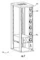
- FIG. 7illustrates a modular UPS rack according to additional embodiments of the present invention.
- FIG. 8illustrates a power interconnect assembly according to some embodiments of the present invention.
- FIG. 9illustrates a modular electronic system according to some embodiments of the present invention.
- FIG. 10is a flowchart illustrating exemplary operations for providing a power distribution in an electronic system according to further embodiments of the present invention.
- FIG. 1illustrates a modular electronic system 100 according to some embodiments of the present invention.
- the systemincludes a plurality of equipment racks 140 and a power distribution rack 110 that is configured to distribute power to the equipment racks 140 .
- the system 100also includes a UPS rack 120 and a battery rack 130 , which are configured to interoperate with the power distribution rack 110 .
- the UPS rack 120may include one or more UPSs 122 , and is configured to receive utility power from the power distribution rack 110 over a power input cable 111 and to provide power back to the power distribution rack 110 over a power output cable 113 .
- the UPS rack 120may provide conditioned and/or backup power, e.g., from batteries 132 in the battery rack 130 via a battery cable 121 , to the power distribution unit 110 for distribution to the equipment racks 140 .
- FIG. 1illustrates a battery rack 130 and batteries 132 separate from the UPSs 122
- the UPSs 122may include integrated batteries, which may or may not be supported by additional external batteries.
- the equipment racks 140are configured to house or otherwise support electronic equipment 142 , such as server computers, routers, disk drives, tape drives or other computing or communications hardware.
- Each of the equipment racks 140includes one or more power input cables 141 , each having a first end fixedly attached to the equipment rack 140 , e.g., using a cable clamp, strain relief or other fixed mounting structure.
- Each power input cable 141has a connector 143 is attached at a second end. It will be understood that each equipment rack 140 may have more than one power input cable 141 .
- multiple power input cables 141may be provided to meet particular load requirements and/or to provide connection to redundant power sources, as described in greater detail below.
- the power input cables 141may have respective lengths that correspond to respective distances between the respective equipment racks 140 and the power distribution rack 110 , as also discussed in greater detail below.
- Each connector 143is configured to be pluggably connected to a mating connector 117 of the power distribution rack 110 to provide power to the equipment racks 140 .
- the number of equipment racks 140 and power distribution racks 110 , UPS racks 120 and/or battery racks 130 and the relative arrangement thereofmay be determined, and cable lengths for the equipment racks 140 may be specified and fabricated as part of the construction of the equipment racks 140 at the factory.
- Prefabricated equipment racks 140 and prefabricated power distribution, UPS and/or battery racks 110 , 120 , 130may be provided to the installation site, where the equipment racks 140 may be populated with equipment and integrated with the power distribution rack 110 by pluggably mating the connectors 117 , 143 .
- the power distribution rack 110 , UPS rack 120 and/or battery rack 130may also be constructed in a modular fashion, such that they may be constructed component-by-component at the factory and/or field.
- these power equipment racksmay use a standard form factor (e.g., 19-inch) rack that may be populated with power modules and modular interconnect assemblies as shown, for example, in a copending U.S. patent application Ser. No. 11/378,140, entitled “Modular UPS Systems and Methods Using Modular Interconnect Assemblies,” filed concurrently herewith and incorporated herein by reference in its entirety.
- An installationmay be expanded by addition of new equipment racks 140 and/or power racks, which may be prefabricated at the factory based on knowledge of the existing layout.
- Circuit layoute.g., distribution of loads among phases and/or branch circuits, may also be easily modified by changing connections among the connectors 117 , 143 at the power distribution rack 110 .
- Such flexibilitymay be valuable, for example, when a UPS module or other piece of equipment needs to be removed for maintenance and/or if the nature of the load changes (e.g., changes caused by network reconfiguration and/or expansion).
- the connectors 117 , 143may have any of a number of different configurations and/or form factors, including blade/receptacle arrangements or other structures that provide pluggable electrical coupling.
- the power distribution rack 110may also include a plurality of circuit interruption devices, here shown as circuit breakers 112 , which are coupled to the connectors 117 .
- the breakers 112are coupled to a bypass switch 114 , which is also coupled to a transformer 116 , here shown as receiving power from a utility source 115 .
- the bypass switch 114is operative to bypass one or more UPSs 122 in the UPS rack 120 such that the breakers 112 may be tied directly to the transformer 116 .
- components, such as the breakers 112 , bypass switch 114 or transformer 116shown as included in the power distribution rack 110 in FIG. 1 , may be provided in a different rack or enclosure, and coupled to the power distribution rack 110 via cabling.
- the bypass switch 114 and/or transformer 116may be included in the UPS rack 120 or in another rack.
- FIG. 2provides a rear prospective view of a power distribution rack 210 and an equipment rack 240 according to further embodiments of the present invention.
- FIG. 3provides a side view of the power distribution rack 210 .
- the power distribution rack 210includes a frame 215 , for example, a housing, structural support members and/or other frame components.
- the frame 215supports a breaker panel 212 , which is accessible at a front face 213 of the power distribution rack 210 .
- the frame 215also supports a plurality of outlets 218 accessible at a back face 217 of the power distribution rack 210 .
- the equipment rack 240includes a frame 245 that supports electronic equipment 242 , for example, computers, routers, hubs, disk drives, and/or other computing or communications equipment.
- An outlet assembly 244 mounted in and/or on the frame 245includes outlets 247 that are configured to pluggably mate with power input cables from the electronic equipment 242 , thus providing a power distribution network for the equipment rack 240 .
- a first end of a power input cable 241 of the equipment rack 240is fixedly attached to the power outlet assembly 244 .
- a connector 243is attached at a second end of the power input cable 241 .
- the connector 243is configured to pluggably mate with one of the outlets 218 of the power distribution rack 210 .
- the equipment rack 240may have more than one power input cable 241 .
- the equipment rack 240may include multiple outlet assemblies like the assembly 244 , with respective power input cables fixedly attached thereto.
- FIGS. 2 and 3illustrate placement of breakers 212 and outlets 218 and on respective front and back faces 213 , 217 of a power distribution rack
- either of the outlets 218 or breakers 212may be provided on a side face of a power distribution rack, e.g., breakers could be accessible on the side for a power distribution rack placed at the end of a row of racks.
- FIGS. 4 and 5illustrate another exemplary configuration of circuit breakers 420 and output connectors 430 for a power distribution rack according to further embodiments of the present invention.
- the circuit breakers 420 and outletsmay be mounted on respective front and back faces of a power distribution assembly 410 (e.g., a breaker panel) that is configured to be mounted in a power distribution rack frame.
- a power cable 440may extend from the power distribution assembly 410 for connection to a power source, e.g., to a bypass switch and/or UPS as illustrated in FIG. 1 .
- a connectionmay be made, for example, via a modular power interconnect assembly as described with reference to FIGS. 7 and 8 below.
- connectors of a power distribution racksuch as the connectors of the power distribution racks 110 , 210 shown in FIGS. 1 and 2
- outlet connectors 610may be grouped by phase (A,B,C).
- phaseA,B,C
- Such an approachmay make balancing and rebalancing of loads more convenient, as multiple power connections may be provided at a single location and their phase and/or branch circuit identity clearly identified to personnel.
- FIG. 7illustrates an exemplary configuration for a UPS rack 710 that may be used in a modular electronic system, such as the system 100 of FIG. 1 , according to further embodiments of the present invention.
- the UPS rack 710includes a frame 712 that is configured to support one or more UPS modules 716 .
- the UPS modules 716are electrically coupled to a modular power interconnect assembly 714 , which is shown in greater detail in FIG. 8 .
- the power interconnect assembly 714may be configured to provide AC and/or DC power connections for the UPS modules 716 , which, as shown in FIG. 8 , may be connected to the power interconnect assembly 714 via connectors 810 .
- the connectors 810may be, for example, “fingerproof” connectors, such as the Power Pak® line of connectors produced by Anderson Power Products.
- DC and/or AC power connections for the power interconnect assembly 714may be provided, for example, via an end 820 of the power interconnect assembly 714 .
- the power distribution rack 110 illustrated in FIG. 1may incorporate a modular interconnect assembly along the lines of the power interconnect assembly 714 to connect the breaker panel 112 , bypass switch 114 and transformer 116 , and similar structures may be used, for example, for battery banks and other UPS system components.
- Modular power interconnect assemblies and power module rack configurations using such assembliesthat may be used in accordance with some embodiments of the present invention are generally described in the aforementioned U.S. patent application Ser. No. 11/378,140, entitled “Modular UPS Systems and Methods Using Modular Interconnect Assemblies.”
- FIG. 9illustrates a modular electronic system 900 according to further embodiments of the present invention in which equipment racks 140 are served from multiple power sources.
- the system 900includes many of the components illustrated in FIG. 1 , with like elements indicated by like reference numbers.
- the system 900further differs in that it provides power to the equipment racks 140 from multiple power distribution racks 110 , supported by multiple UPS racks 120 .
- Such a configurationmay be used, for example, in applications in which the load equipment 142 is configured to receive power from redundant power sources.
- some server rack implementationsmay include multiple DC power supplies that have DC outputs that are paralleled for redundant DC power provision to server modules in the server rack.
- respective UPS-backed AC power sourcessuch as the respective power distribution racks 140 shown in FIG. 9 , may be coupled to respective ones of the multiple DC power supplies in the server rack.
- FIG. 10is a flowchart illustrating exemplary operations for providing power distribution in an electronic system, such as a data processing or telecommunications system, according to some embodiments of the present invention.
- a layout of power distribution and equipment racksis determined (block 1010 ).
- Power distribution rack requirementse.g., number and size of conductors, breaker requirements, and the like, are determined, along with the power input cable requirements for the equipment racks that are to be connected to the power distribution racks (block 1020 ). For example, in this step, the number and length of power input cables of each of the equipment racks may be determined based on the layout of the system.
- equipment racks with the appropriate power input cables and power distribution racks with the appropriate capabilitiesmay be procured (blocks 1030 , 1040 ).
- the procured racksare then arranged at the installation site (block 1050 ).
- the connectors of the equipment rack cablesare then mated to appropriate connectors of the power distribution racks (block 1060 ).
- the matingmay be based on loading or other considerations.
- the systemmay be operated, e.g., the equipment racks may be energized (block 1070 ).
Landscapes
- Engineering & Computer Science (AREA)
- Computer Hardware Design (AREA)
- General Engineering & Computer Science (AREA)
- Microelectronics & Electronic Packaging (AREA)
- Details Of Connecting Devices For Male And Female Coupling (AREA)
- Power Sources (AREA)
Abstract
Description
Claims (17)
Priority Applications (3)
| Application Number | Priority Date | Filing Date | Title |
|---|---|---|---|
| US11/378,054US7542268B2 (en) | 2006-03-17 | 2006-03-17 | Modular electronic systems and methods using flexible power distribution unit interface |
| CN2007101006611ACN101071327B (en) | 2006-03-17 | 2007-03-16 | Modular electronic systems and methods using flexible power distribution unit interface |
| EP07005481AEP1835793A3 (en) | 2006-03-17 | 2007-03-16 | Modular electronic systems and methods using flexible power distribution unit interface |
Applications Claiming Priority (1)
| Application Number | Priority Date | Filing Date | Title |
|---|---|---|---|
| US11/378,054US7542268B2 (en) | 2006-03-17 | 2006-03-17 | Modular electronic systems and methods using flexible power distribution unit interface |
Publications (2)
| Publication Number | Publication Date |
|---|---|
| US20070217128A1 US20070217128A1 (en) | 2007-09-20 |
| US7542268B2true US7542268B2 (en) | 2009-06-02 |
Family
ID=38222486
Family Applications (1)
| Application Number | Title | Priority Date | Filing Date |
|---|---|---|---|
| US11/378,054Active2026-05-24US7542268B2 (en) | 2006-03-17 | 2006-03-17 | Modular electronic systems and methods using flexible power distribution unit interface |
Country Status (3)
| Country | Link |
|---|---|
| US (1) | US7542268B2 (en) |
| EP (1) | EP1835793A3 (en) |
| CN (1) | CN101071327B (en) |
Cited By (22)
| Publication number | Priority date | Publication date | Assignee | Title |
|---|---|---|---|---|
| US20080309160A1 (en)* | 2007-06-14 | 2008-12-18 | Hewlett-Packard Development Company, L. P. | Modular blade enclosure power subsystem disign |
| US20110261506A1 (en)* | 2010-04-21 | 2011-10-27 | Schneider Electric Sachsenwerk Gmbh | Electrical switchgear, in particular switchgear for medium voltage |
| US20110261507A1 (en)* | 2010-04-21 | 2011-10-27 | Weighell Christopher A | Electrical Distribution Panel |
| WO2011156127A3 (en)* | 2010-06-09 | 2012-04-19 | Microsoft Corporation | Rack-based uninterruptible power supply |
| US20120098342A1 (en)* | 2010-10-22 | 2012-04-26 | Eaton Corporation | High density uninterruptible power supplies and related systems and power distribution units |
| US20120120559A1 (en)* | 2010-11-09 | 2012-05-17 | Server Technology, Inc. | Equipment-rack power distribution system with cooling |
| US8487473B2 (en) | 2010-06-24 | 2013-07-16 | Microsoft Corporation | Hierarchical power smoothing |
| US20130314848A1 (en)* | 2012-05-28 | 2013-11-28 | Hon Hai Precision Industry Co., Ltd. | Power distribution unit and server cabinet with the power distribution unit |
| US8611104B1 (en) | 2009-10-15 | 2013-12-17 | Power-One, Inc. | Modular power supply interconnection system with pluggable interface |
| US20140125128A1 (en)* | 2012-11-07 | 2014-05-08 | Electronics And Telecommunications Research Institute | Power redundancy apparatus for rack-mounted server |
| US8750393B1 (en) | 2012-12-21 | 2014-06-10 | International Business Machines Corporation | Determining the configuration of a power distribution system |
| US8782443B2 (en) | 2010-05-25 | 2014-07-15 | Microsoft Corporation | Resource-based adaptive server loading |
| US8941976B1 (en)* | 2011-01-25 | 2015-01-27 | Western Digital Technologies, Inc. | Configurable powerline Ethernet adapter and power supply |
| US8952566B2 (en) | 2010-10-26 | 2015-02-10 | Microsoft Technology Licensing, Llc | Chassis slots accepting battery modules and other module types |
| US9374926B1 (en)* | 2015-01-16 | 2016-06-21 | General Electric Company | Systems and methods for power conversion and distribution |
| US20160262283A1 (en)* | 2010-12-23 | 2016-09-08 | Amazon Technologies, Inc. | System with movable computing devices |
| US9491895B2 (en) | 2013-03-03 | 2016-11-08 | General Electric Company | Power distribution rack bus bar assembly and method of assembling the same |
| US20170111451A1 (en)* | 2015-10-15 | 2017-04-20 | LiThul LLC | Methods and Apparatus For Remotely Monitoring Access To Rack Mounted Server Cabinets |
| US9772663B2 (en) | 2015-10-15 | 2017-09-26 | LiThul LLC | System and method for distributing power to rack mounted servers |
| US10499531B2 (en)* | 2018-04-18 | 2019-12-03 | Schneider Electric It Corporation | Rack level network switch |
| US10721834B2 (en) | 2016-03-04 | 2020-07-21 | Ge Aviation Systems Limited | Method and apparatus for modular power distribution |
| US20240023268A1 (en)* | 2022-07-15 | 2024-01-18 | Schneider Electric It Corporation | Optimized micro data center |
Families Citing this family (21)
| Publication number | Priority date | Publication date | Assignee | Title |
|---|---|---|---|---|
| US7561411B2 (en) | 2006-03-17 | 2009-07-14 | Eaton Corporation | Uninterruptible power distribution systems and methods using distributed power distribution units |
| US11076517B2 (en)* | 2007-06-14 | 2021-07-27 | Switch, Ltd. | Tri-redundant data center power supply system |
| KR100921682B1 (en) | 2007-09-21 | 2009-10-15 | 한국전자통신연구원 | Rack power supply device for high efficiency data center operation, power supply system and power supply method using the same |
| US8154856B2 (en)* | 2009-12-16 | 2012-04-10 | Lineage Power Corporation | Cabinet for a power distribution system |
| US8587950B2 (en) | 2011-05-31 | 2013-11-19 | Server Technology, Inc. | Method and apparatus for multiple input power distribution to adjacent outputs |
| TW201335739A (en)* | 2012-02-29 | 2013-09-01 | Quanta Comp Inc | Server system |
| JP6202591B2 (en)* | 2012-10-18 | 2017-09-27 | 株式会社日立システムズ | Power distribution equipment |
| US9733682B2 (en)* | 2013-12-19 | 2017-08-15 | VCE IP Holding Company LLC | Scalable computing rack power distribution unit |
| US9846467B2 (en)* | 2014-02-14 | 2017-12-19 | Amazon Technologies, Inc. | Power routing assembly for data center |
| US9929778B2 (en)* | 2014-04-07 | 2018-03-27 | Google Llc | Systems for enabling chassis-coupled modular mobile electronic devices |
| EP3140895B1 (en)* | 2014-05-06 | 2019-07-10 | Vertiv Corporation | Apparatus for distributing power |
| FR3024935B1 (en)* | 2014-08-14 | 2018-03-02 | Zodiac Aero Electric | CONNECTION SYSTEM FOR PROTECTING CARDS OF A DISTRIBUTION SYSTEM AND RACK INCORPORATING SAID SYSTEM |
| US9748799B2 (en) | 2015-02-12 | 2017-08-29 | Eaton Corporation | Adaptable external battery modules and related systems |
| US9466954B1 (en)* | 2015-05-29 | 2016-10-11 | Hewlett Packard Enterprise Development Lp | Rack mountable power distribution units |
| US10476298B1 (en) | 2015-09-02 | 2019-11-12 | Amazon Technologies, Inc. | Elevated automatic transfer switch cabinet |
| GB201517676D0 (en)* | 2015-10-07 | 2015-11-18 | Eaton Ind France Sas | Power distribution module for a rack for electronic equipment |
| US9727100B1 (en)* | 2015-11-04 | 2017-08-08 | VCE IP Holding Company LLC | Power distribution unit/power outlet unit for a distributed computing system |
| US10130000B2 (en) | 2016-10-11 | 2018-11-13 | Abb Schweiz Ag | Power connector for electronic equipment supported by a rack assembly |
| US10985601B2 (en)* | 2018-01-10 | 2021-04-20 | Eaton Intelligent Power Limited | Methods, systems and devices for extending run-times of uninterruptible power supplies (UPSs) |
| EP3843240B1 (en)* | 2019-12-23 | 2023-04-19 | Zumtobel Lighting GmbH | Central unit for supplying emergency lighting means on a dc bus |
| US12068635B2 (en)* | 2022-05-13 | 2024-08-20 | Schneider Electric It Corporation | Modular power system |
Citations (24)
| Publication number | Priority date | Publication date | Assignee | Title |
|---|---|---|---|---|
| US3054024A (en)* | 1959-03-11 | 1962-09-11 | Polytron Ind Inc | Compatible module structure |
| US5675194A (en)* | 1996-06-07 | 1997-10-07 | Walker Systems, Inc. | Modular power distribution system |
| US6201319B1 (en)* | 1998-07-14 | 2001-03-13 | American Power Conversion | Uninterruptible power supply |
| US6301095B1 (en)* | 1999-12-23 | 2001-10-09 | 3Com Corporation | System and method of distributing power to a plurality of electronic modules housed within an electronics cabinet |
| USRE37592E1 (en)* | 1994-03-18 | 2002-03-19 | Tor Andrew Alden | Identification icon indicia for plug-in units of a power distribution system |
| US6442017B1 (en)* | 2000-08-09 | 2002-08-27 | Server Technology, Inc. | Battery-power distribution panel for network equipment |
| US20020187682A1 (en)* | 2001-06-06 | 2002-12-12 | Lincoln Clifford F. | Electrical load balancing power module |
| US20030223196A1 (en)* | 2002-05-31 | 2003-12-04 | Racksaver, Inc. | Rack mountable computer component fan cooling arrangement and method |
| US20040000815A1 (en) | 2002-06-28 | 2004-01-01 | Pereira Robert A. | Modular power distribution system for use in computer equipment racks |
| US20040130868A1 (en)* | 2003-01-08 | 2004-07-08 | Schwartz William H. | Cooling system including redundant fan controllers |
| US20040231875A1 (en) | 2001-03-20 | 2004-11-25 | Neil Rasmussen | Adjustable scalable rack power system and method |
| US6844716B1 (en)* | 2002-11-13 | 2005-01-18 | Hydrohoist International, Inc. | Breakaway utility pedestal with programmable internal metering for marine and recreational vehicles |
| US6867966B2 (en)* | 2002-05-31 | 2005-03-15 | Verari Systems, Inc. | Method and apparatus for rack mounting computer components |
| US6882530B2 (en)* | 2003-03-31 | 2005-04-19 | Sun Microsystems, Inc. | Integrated component rack and AC power distribution |
| US20050094357A1 (en) | 2003-10-30 | 2005-05-05 | Ewing Carrel W. | Electrical circuit apparatus with fuse access section |
| US20050162019A1 (en)* | 2004-01-23 | 2005-07-28 | Masciarelli Francis J. | Methods and apparatus for providing uninterruptible power |
| US20050185363A1 (en)* | 2002-01-02 | 2005-08-25 | American Power Conversion Corporation | Toolless mounting system and method for an adjustable scalable rack power system |
| US6967283B2 (en) | 2001-03-20 | 2005-11-22 | American Power Conversion Corporation | Adjustable scalable rack power system and method |
| US20060005985A1 (en)* | 2002-09-26 | 2006-01-12 | L Henaff Jean-Jacques | Electronics housings and associated connectors for cable/wiring distribution system |
| US7046514B2 (en)* | 2003-03-19 | 2006-05-16 | American Power Conversion Corporation | Data center cooling |
| US7145772B2 (en)* | 2003-03-19 | 2006-12-05 | American Power Conversion Corporation | Data center cooling system |
| US7196900B2 (en)* | 2004-05-21 | 2007-03-27 | Server Technology, Inc. | Adaptable rack mountable power distribution apparatus |
| US20070165377A1 (en)* | 2006-01-19 | 2007-07-19 | American Power Conversion Corporation | Cooling system and method |
| US7252524B1 (en)* | 2006-03-17 | 2007-08-07 | Eaton Power Quality Corporation | Power interconnect assemblies and methods for configuring the same |
Family Cites Families (1)
| Publication number | Priority date | Publication date | Assignee | Title |
|---|---|---|---|---|
| US6976112B2 (en)* | 2002-11-27 | 2005-12-13 | International Business Machines Corporation | Apparatus, method and program product for automatically distributing power to modules inserted in live chassis |
- 2006
- 2006-03-17USUS11/378,054patent/US7542268B2/enactiveActive
- 2007
- 2007-03-16CNCN2007101006611Apatent/CN101071327B/ennot_activeExpired - Fee Related
- 2007-03-16EPEP07005481Apatent/EP1835793A3/ennot_activeWithdrawn
Patent Citations (29)
| Publication number | Priority date | Publication date | Assignee | Title |
|---|---|---|---|---|
| US3054024A (en)* | 1959-03-11 | 1962-09-11 | Polytron Ind Inc | Compatible module structure |
| USRE37592E1 (en)* | 1994-03-18 | 2002-03-19 | Tor Andrew Alden | Identification icon indicia for plug-in units of a power distribution system |
| US5675194A (en)* | 1996-06-07 | 1997-10-07 | Walker Systems, Inc. | Modular power distribution system |
| US6201319B1 (en)* | 1998-07-14 | 2001-03-13 | American Power Conversion | Uninterruptible power supply |
| US6301095B1 (en)* | 1999-12-23 | 2001-10-09 | 3Com Corporation | System and method of distributing power to a plurality of electronic modules housed within an electronics cabinet |
| US6442017B1 (en)* | 2000-08-09 | 2002-08-27 | Server Technology, Inc. | Battery-power distribution panel for network equipment |
| US6967283B2 (en) | 2001-03-20 | 2005-11-22 | American Power Conversion Corporation | Adjustable scalable rack power system and method |
| US20040231875A1 (en) | 2001-03-20 | 2004-11-25 | Neil Rasmussen | Adjustable scalable rack power system and method |
| US20020187682A1 (en)* | 2001-06-06 | 2002-12-12 | Lincoln Clifford F. | Electrical load balancing power module |
| US20050185363A1 (en)* | 2002-01-02 | 2005-08-25 | American Power Conversion Corporation | Toolless mounting system and method for an adjustable scalable rack power system |
| US20030223196A1 (en)* | 2002-05-31 | 2003-12-04 | Racksaver, Inc. | Rack mountable computer component fan cooling arrangement and method |
| US20050083651A1 (en)* | 2002-05-31 | 2005-04-21 | Smith John V. | Method and apparatus for rack mounting computer components |
| US20050024825A1 (en)* | 2002-05-31 | 2005-02-03 | Smith John V. | Rack mountable computer component fan cooling arrangement and method |
| US6867966B2 (en)* | 2002-05-31 | 2005-03-15 | Verari Systems, Inc. | Method and apparatus for rack mounting computer components |
| US20050068716A1 (en)* | 2002-06-28 | 2005-03-31 | Pereira Robert A. | Modular power distribution system for use in computer equipment racks |
| US20040000815A1 (en) | 2002-06-28 | 2004-01-01 | Pereira Robert A. | Modular power distribution system for use in computer equipment racks |
| US20060005985A1 (en)* | 2002-09-26 | 2006-01-12 | L Henaff Jean-Jacques | Electronics housings and associated connectors for cable/wiring distribution system |
| US6844716B1 (en)* | 2002-11-13 | 2005-01-18 | Hydrohoist International, Inc. | Breakaway utility pedestal with programmable internal metering for marine and recreational vehicles |
| US20040130868A1 (en)* | 2003-01-08 | 2004-07-08 | Schwartz William H. | Cooling system including redundant fan controllers |
| US7145772B2 (en)* | 2003-03-19 | 2006-12-05 | American Power Conversion Corporation | Data center cooling system |
| US7046514B2 (en)* | 2003-03-19 | 2006-05-16 | American Power Conversion Corporation | Data center cooling |
| US6882530B2 (en)* | 2003-03-31 | 2005-04-19 | Sun Microsystems, Inc. | Integrated component rack and AC power distribution |
| US20050094357A1 (en) | 2003-10-30 | 2005-05-05 | Ewing Carrel W. | Electrical circuit apparatus with fuse access section |
| US7116550B2 (en)* | 2003-10-30 | 2006-10-03 | Server Technology, Inc. | Electrical circuit apparatus with fuse access section |
| US20050162019A1 (en)* | 2004-01-23 | 2005-07-28 | Masciarelli Francis J. | Methods and apparatus for providing uninterruptible power |
| US7196900B2 (en)* | 2004-05-21 | 2007-03-27 | Server Technology, Inc. | Adaptable rack mountable power distribution apparatus |
| US20070159775A1 (en)* | 2004-05-21 | 2007-07-12 | Server Technology, Inc. | Adaptable rack mountable power distribution apparatus |
| US20070165377A1 (en)* | 2006-01-19 | 2007-07-19 | American Power Conversion Corporation | Cooling system and method |
| US7252524B1 (en)* | 2006-03-17 | 2007-08-07 | Eaton Power Quality Corporation | Power interconnect assemblies and methods for configuring the same |
Non-Patent Citations (1)
| Title |
|---|
| Extended European Search Report and Written Opinion (8 pages) corresponding to European Application No. 07005481.2; Dated: Mar. 2, 2009. |
Cited By (32)
| Publication number | Priority date | Publication date | Assignee | Title |
|---|---|---|---|---|
| US20080309160A1 (en)* | 2007-06-14 | 2008-12-18 | Hewlett-Packard Development Company, L. P. | Modular blade enclosure power subsystem disign |
| US8611104B1 (en) | 2009-10-15 | 2013-12-17 | Power-One, Inc. | Modular power supply interconnection system with pluggable interface |
| US20140063693A1 (en)* | 2010-04-21 | 2014-03-06 | Christopher A. Weighell | Electrical Distribution Panel |
| US9118170B2 (en)* | 2010-04-21 | 2015-08-25 | Schneider Electric Sachsenwerk Gmbh | Electrical switchgear, in particular switchgear for medium voltage |
| US8982539B2 (en)* | 2010-04-21 | 2015-03-17 | Christopher Weighell | Electrical distribution panel |
| US8570714B2 (en)* | 2010-04-21 | 2013-10-29 | Christopher A. Weighell | Electrical distribution panel |
| US20110261507A1 (en)* | 2010-04-21 | 2011-10-27 | Weighell Christopher A | Electrical Distribution Panel |
| US20110261506A1 (en)* | 2010-04-21 | 2011-10-27 | Schneider Electric Sachsenwerk Gmbh | Electrical switchgear, in particular switchgear for medium voltage |
| US8782443B2 (en) | 2010-05-25 | 2014-07-15 | Microsoft Corporation | Resource-based adaptive server loading |
| US8384244B2 (en) | 2010-06-09 | 2013-02-26 | Microsoft Corporation | Rack-based uninterruptible power supply |
| WO2011156127A3 (en)* | 2010-06-09 | 2012-04-19 | Microsoft Corporation | Rack-based uninterruptible power supply |
| US8487473B2 (en) | 2010-06-24 | 2013-07-16 | Microsoft Corporation | Hierarchical power smoothing |
| US8587929B2 (en)* | 2010-10-22 | 2013-11-19 | Eaton Corporation | High density uninterruptible power supplies and related systems and power distribution units |
| US20120098342A1 (en)* | 2010-10-22 | 2012-04-26 | Eaton Corporation | High density uninterruptible power supplies and related systems and power distribution units |
| US8952566B2 (en) | 2010-10-26 | 2015-02-10 | Microsoft Technology Licensing, Llc | Chassis slots accepting battery modules and other module types |
| US9219353B2 (en)* | 2010-11-09 | 2015-12-22 | Server Technology, Inc. | Equipment-rack power distribution system with cooling |
| US20120120559A1 (en)* | 2010-11-09 | 2012-05-17 | Server Technology, Inc. | Equipment-rack power distribution system with cooling |
| US20160262283A1 (en)* | 2010-12-23 | 2016-09-08 | Amazon Technologies, Inc. | System with movable computing devices |
| US10237998B2 (en)* | 2010-12-23 | 2019-03-19 | Amazon Technologies, Inc. | System with movable computing devices |
| US8941976B1 (en)* | 2011-01-25 | 2015-01-27 | Western Digital Technologies, Inc. | Configurable powerline Ethernet adapter and power supply |
| US20130314848A1 (en)* | 2012-05-28 | 2013-11-28 | Hon Hai Precision Industry Co., Ltd. | Power distribution unit and server cabinet with the power distribution unit |
| US8797751B2 (en)* | 2012-05-28 | 2014-08-05 | Hong Fu Jin Precision Industry (Shenzhen) Co., Ltd. | Power distribution unit and server cabinet with the power distribution unit |
| US20140125128A1 (en)* | 2012-11-07 | 2014-05-08 | Electronics And Telecommunications Research Institute | Power redundancy apparatus for rack-mounted server |
| US8750393B1 (en) | 2012-12-21 | 2014-06-10 | International Business Machines Corporation | Determining the configuration of a power distribution system |
| US8792569B2 (en) | 2012-12-21 | 2014-07-29 | International Business Machines Corporation | Power distribution system utilizing digital communications to determine the configuration thereof |
| US9491895B2 (en) | 2013-03-03 | 2016-11-08 | General Electric Company | Power distribution rack bus bar assembly and method of assembling the same |
| US9374926B1 (en)* | 2015-01-16 | 2016-06-21 | General Electric Company | Systems and methods for power conversion and distribution |
| US20170111451A1 (en)* | 2015-10-15 | 2017-04-20 | LiThul LLC | Methods and Apparatus For Remotely Monitoring Access To Rack Mounted Server Cabinets |
| US9772663B2 (en) | 2015-10-15 | 2017-09-26 | LiThul LLC | System and method for distributing power to rack mounted servers |
| US10721834B2 (en) | 2016-03-04 | 2020-07-21 | Ge Aviation Systems Limited | Method and apparatus for modular power distribution |
| US10499531B2 (en)* | 2018-04-18 | 2019-12-03 | Schneider Electric It Corporation | Rack level network switch |
| US20240023268A1 (en)* | 2022-07-15 | 2024-01-18 | Schneider Electric It Corporation | Optimized micro data center |
Also Published As
| Publication number | Publication date |
|---|---|
| EP1835793A2 (en) | 2007-09-19 |
| CN101071327B (en) | 2011-05-11 |
| EP1835793A3 (en) | 2009-04-01 |
| CN101071327A (en) | 2007-11-14 |
| US20070217128A1 (en) | 2007-09-20 |
Similar Documents
| Publication | Publication Date | Title |
|---|---|---|
| US7542268B2 (en) | Modular electronic systems and methods using flexible power distribution unit interface | |
| EP2127510B1 (en) | Uninterruptible power distribution systems and methods using distributed power distribution units | |
| US7760516B2 (en) | Modular UPS systems and methods using modular interconnect assemblies | |
| US7252524B1 (en) | Power interconnect assemblies and methods for configuring the same | |
| US9209622B2 (en) | Rack power distribution unit with detachable cables | |
| CA2440454C (en) | Adjustable scalable rack power system and method | |
| US9081568B1 (en) | Electrical power system with automatic transfer switch failure protection | |
| US11316365B2 (en) | Modular uninterruptible power supply and power distribution system | |
| US20070046103A1 (en) | System for distributing AC power wthin an equipment rack | |
| US20050068716A1 (en) | Modular power distribution system for use in computer equipment racks | |
| US8500465B1 (en) | Adaptive cable connection system | |
| US8836175B1 (en) | Power distribution system for rack-mounted equipment | |
| US10936027B2 (en) | Power distribution system | |
| Wisehart et al. | CABLE AND POWER. |
Legal Events
| Date | Code | Title | Description |
|---|---|---|---|
| AS | Assignment | Owner name:EATON POWER QUALITY CORPORATION, OHIO Free format text:ASSIGNMENT OF ASSIGNORS INTEREST;ASSIGNOR:JOHNSON, JR., ROBERT W;REEL/FRAME:017599/0386 Effective date:20060504 | |
| AS | Assignment | Owner name:EATON CORPORATION, OHIO Free format text:CERTIFICATE;ASSIGNOR:EATON ELECTRICAL INC.;REEL/FRAME:022604/0368 Effective date:20080117 Owner name:EATON ELECTRICAL INC., OHIO Free format text:CHANGE OF NAME;ASSIGNOR:EATON POWER QUALITY CORPORATION;REEL/FRAME:022601/0938 Effective date:20060428 | |
| STCF | Information on status: patent grant | Free format text:PATENTED CASE | |
| FPAY | Fee payment | Year of fee payment:4 | |
| FPAY | Fee payment | Year of fee payment:8 | |
| AS | Assignment | Owner name:EATON INTELLIGENT POWER LIMITED, IRELAND Free format text:ASSIGNMENT OF ASSIGNORS INTEREST;ASSIGNOR:EATON CORPORATION;REEL/FRAME:048855/0626 Effective date:20171231 | |
| MAFP | Maintenance fee payment | Free format text:PAYMENT OF MAINTENANCE FEE, 12TH YEAR, LARGE ENTITY (ORIGINAL EVENT CODE: M1553); ENTITY STATUS OF PATENT OWNER: LARGE ENTITY Year of fee payment:12 |