US7540874B2 - Method and device for use in osteotomy - Google Patents
Method and device for use in osteotomyDownload PDFInfo
- Publication number
- US7540874B2 US7540874B2US10/854,892US85489204AUS7540874B2US 7540874 B2US7540874 B2US 7540874B2US 85489204 AUS85489204 AUS 85489204AUS 7540874 B2US7540874 B2US 7540874B2
- Authority
- US
- United States
- Prior art keywords
- bone
- screw
- fixation device
- portions
- cutting
- Prior art date
- Legal status (The legal status is an assumption and is not a legal conclusion. Google has not performed a legal analysis and makes no representation as to the accuracy of the status listed.)
- Expired - Lifetime, expires
Links
- 238000000034methodMethods0.000titleclaimsabstractdescription22
- 210000000988bone and boneAnatomy0.000claimsabstractdescription135
- 230000035876healingEffects0.000claimsdescription8
- 210000001519tissueAnatomy0.000abstractdescription3
- 210000003205muscleAnatomy0.000abstract1
- 210000003491skinAnatomy0.000abstract1
- 210000002435tendonAnatomy0.000abstract1
- 210000000623ulnaAnatomy0.000description26
- 230000006835compressionEffects0.000description12
- 238000007906compressionMethods0.000description12
- 210000002414legAnatomy0.000description8
- 238000004904shorteningMethods0.000description7
- 210000000845cartilageAnatomy0.000description5
- 230000006378damageEffects0.000description5
- 208000027418Wounds and injuryDiseases0.000description4
- 239000007943implantSubstances0.000description4
- 208000014674injuryDiseases0.000description4
- 210000000707wristAnatomy0.000description4
- 208000010392Bone FracturesDiseases0.000description3
- 208000037265diseases, disorders, signs and symptomsDiseases0.000description3
- 208000035475disorderDiseases0.000description3
- 208000037873arthrodesisDiseases0.000description2
- 210000004872soft tissueAnatomy0.000description2
- 208000024891symptomDiseases0.000description2
- 235000012431wafersNutrition0.000description2
- 208000034657ConvalescenceDiseases0.000description1
- 210000003423ankleAnatomy0.000description1
- 230000002917arthritic effectEffects0.000description1
- 206010003246arthritisDiseases0.000description1
- 230000003111delayed effectEffects0.000description1
- 238000005553drillingMethods0.000description1
- 210000001513elbowAnatomy0.000description1
- 239000000835fiberSubstances0.000description1
- 230000004927fusionEffects0.000description1
- 210000002411hand boneAnatomy0.000description1
- 238000011065in-situ storageMethods0.000description1
- 210000003127kneeAnatomy0.000description1
- 239000002184metalSubstances0.000description1
- 238000002360preparation methodMethods0.000description1
- 230000006641stabilisationEffects0.000description1
- 238000011105stabilizationMethods0.000description1
Images


Classifications
- A—HUMAN NECESSITIES
- A61—MEDICAL OR VETERINARY SCIENCE; HYGIENE
- A61B—DIAGNOSIS; SURGERY; IDENTIFICATION
- A61B17/00—Surgical instruments, devices or methods
- A61B17/56—Surgical instruments or methods for treatment of bones or joints; Devices specially adapted therefor
- A61B17/58—Surgical instruments or methods for treatment of bones or joints; Devices specially adapted therefor for osteosynthesis, e.g. bone plates, screws or setting implements
- A61B17/88—Osteosynthesis instruments; Methods or means for implanting or extracting internal or external fixation devices
- A61B17/8866—Osteosynthesis instruments; Methods or means for implanting or extracting internal or external fixation devices for gripping or pushing bones, e.g. approximators
- A—HUMAN NECESSITIES
- A61—MEDICAL OR VETERINARY SCIENCE; HYGIENE
- A61B—DIAGNOSIS; SURGERY; IDENTIFICATION
- A61B17/00—Surgical instruments, devices or methods
- A61B17/14—Surgical saws
- A61B17/15—Guides therefor
- A—HUMAN NECESSITIES
- A61—MEDICAL OR VETERINARY SCIENCE; HYGIENE
- A61B—DIAGNOSIS; SURGERY; IDENTIFICATION
- A61B17/00—Surgical instruments, devices or methods
- A61B17/56—Surgical instruments or methods for treatment of bones or joints; Devices specially adapted therefor
- A61B17/58—Surgical instruments or methods for treatment of bones or joints; Devices specially adapted therefor for osteosynthesis, e.g. bone plates, screws or setting implements
- A61B17/68—Internal fixation devices, including fasteners and spinal fixators, even if a part thereof projects from the skin
- A61B17/80—Cortical plates, i.e. bone plates; Instruments for holding or positioning cortical plates, or for compressing bones attached to cortical plates
- A61B17/8004—Cortical plates, i.e. bone plates; Instruments for holding or positioning cortical plates, or for compressing bones attached to cortical plates with means for distracting or compressing the bone or bones
- A—HUMAN NECESSITIES
- A61—MEDICAL OR VETERINARY SCIENCE; HYGIENE
- A61B—DIAGNOSIS; SURGERY; IDENTIFICATION
- A61B17/00—Surgical instruments, devices or methods
- A61B17/28—Surgical forceps
- A61B17/2812—Surgical forceps with a single pivotal connection
- A—HUMAN NECESSITIES
- A61—MEDICAL OR VETERINARY SCIENCE; HYGIENE
- A61B—DIAGNOSIS; SURGERY; IDENTIFICATION
- A61B17/00—Surgical instruments, devices or methods
- A61B17/56—Surgical instruments or methods for treatment of bones or joints; Devices specially adapted therefor
- A61B17/58—Surgical instruments or methods for treatment of bones or joints; Devices specially adapted therefor for osteosynthesis, e.g. bone plates, screws or setting implements
- A61B17/68—Internal fixation devices, including fasteners and spinal fixators, even if a part thereof projects from the skin
- A61B17/80—Cortical plates, i.e. bone plates; Instruments for holding or positioning cortical plates, or for compressing bones attached to cortical plates
- A61B17/8004—Cortical plates, i.e. bone plates; Instruments for holding or positioning cortical plates, or for compressing bones attached to cortical plates with means for distracting or compressing the bone or bones
- A61B17/8019—Cortical plates, i.e. bone plates; Instruments for holding or positioning cortical plates, or for compressing bones attached to cortical plates with means for distracting or compressing the bone or bones where the means are a separate tool rather than being part of the plate
Definitions
- the present inventionrelates generally to a method and a device adapted for use in connection with a surgical osteotomy, and more specifically a device for use during a bone-shortening operation for the treatment or correction of deformity related to excessive bone length.
- the present inventionis described in connection with fracture disorders related to the wrist, particularly those that result in misalignment between a first part of a bone named radius, and another part of a bone named ulna, causing interference, for instance in the sigmoid notch of the wrist.
- the inventionis not restricted to this application and can be used when treating bones of the elbow, knee, and ankle. These applications may require a change in the shape of the inventive device related to each specific application, but the same principles are used irrespective of the site of the misalignment. However, the major use of the invention is expected to be for treating deformities and disorders of the distal radial ulnar joint.
- the object of the inventionis to restore an alignment between the radius and the ulna in order to prevent arthritis and to relieve pain as well as to minimize the impaction and pressure between the ulna and the carpus of the wrist.
- Misalignment between the radius and the ulnacan result from injury or idiopathic conditions where the ulna is excessively long in relationship to the radius. Injuries that result in a fracture or dislocation of the radius can end up producing a radius that is too short in relationship to the ulna that allows the prominent distal end of the ulna to impact and apply excessive pressure to the carpus of the wrist, the triangular fibre cartilage that covers the distal end of the ulna.
- Excision of the distal end of the ulnacan relieve the pain resulting from arthritic joints or increased pressure and impaction between the ends of the ulna and the carpus, but it results in an unstable joint, which frequently increases instability of the ulna that produces additional symptoms for which no treatment options can subsequently restore the action of the destroyed joint.
- Partial excision of the end of the ulnastrives to relieve the pressure between the ulna and the carpus while still allowing some portion of the joint to reserve a normal relationship and rotation between the radius and the ulna.
- many patientsexperience significant pain because the normal cartilage and joint contacting between the triangular cartilage and ulna have been removed.
- Removal of the distal ulna and replacement with a prosthetic jointallows for correction of the length of the ulna at the time of joint replacement, and may be satisfactory in older patients, but in younger, active patients the action between the metal surface of the ulna will cause destruction of the normal cartilage of the radius, with which it articulates. The loss of cartilage from the radius can result in recurrence of pain in the patient.
- Arthrodesis of the joint and the creation of a false joint proximalis by removing a segment of bonehave been referred to as the Sauve-Kapandji procedure. Although this can relieve symptoms of pain because the joint is fused, the rate of arthrodesis is unreliable and the false joint below can cause instability, clicking, and pain that is very difficult to treat because the resected bone can cause instability and pain.
- the other methodis to use a cutting guide and then apply a device with a compression screw system to bring the bone ends together.
- the freehand techniquehas a high margin of error and if the bone surfaces are not cut parallel, there is poor coaptation of the bones and a high rate of non-union. Also, the amount of bone removed is very imprecise.
- the technique that uses a cutting guide with the compression screwrequires that the cutting guide be removed before applying the final plate implant. This technique will result in loss of alignment once the cutting guide is removed, as the final implant in the bone being cut cannot be visualized, and if the cutting guide provides any errors because of the way the device is assembled, significant problems may occur.
- the cutting guide from this deviceblocks and prevents the surgeon or physician from viewing the structures around the bone and injury to the bony structures by the saw can occur.
- this deviceuses two separate screws for compression of the osteotomy that cannot be compressed at the same time. As a result, misalignment between the bone surfaces often occurs.
- a method of oblique osteotomy for the bone shorteningis described, which allows for lag screw compression through the plate and can be performed while the plate is already attached to the bone, thus preventing loss of alignment.
- the osteotomycan be directly visualized while the plate is in place in order to make sure that the physician can ensure that the cuts are accurate and that all soft tissues around the bone can be protected.
- a single central screw compressionis all that is needed between the bone ends created to optimise the healing of the osteotomy.
- the object of the inventionis to provide implantable means for bone shortening to restore joint alignment, which overcomes the problems associated with the known art.
- the means according to the inventionhas three functions, (1) bone shortening with an oblique osteotomy, (2) compression screw fixation across the osteotomy, and (3) stabilization with a plate implant that is applied to the bone prior to making the osteotomy.
- the plate implantis applied to the bone with an excavated or recessed portion of the plate centered over the site where the osteotomy is desired.
- the plateis compressed to the bone.
- Pressureis applied to the plate using one or more screws in the distal three holes of the plate.
- Fixation guidesare arranged on the side of the plate and the surgeon selects the width of the bone to be removed based on a cutting guide to be applied in said fixation guides.
- Two, three, or arbitrarily millimetres thick bone waferscan be removed with the guides that will be available.
- the surgeoncan protect the soft tissues with retractors on either side of the bone and directly visualize while the cuts are completed.
- a screwis inserted through one cortex—a 3.5-millimeter screw is inserted through one cortex of the bone to be used as a post for compressing the osteotomy.
- a compression screw deviceis attached to the plate with the aim of bringing the bone ends thus created together for achieving perfect conditions for coaptation of the leg or bone.
- a unique feature of the plateis that it functions both as a drill guide, incorporated in the plate, as well as providing the guide for the osteotomy and device for compressing the bone surfaces.
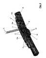
- FIG. 1 ashows in a perspective view on the one hand a part of a bone to be shortened and on the other hand a fixation device to be used for that purpose
- FIG. 1 bshows in an enlarged partial perspective view an upper side of the fixation device exposing a design of apertures therein
- FIG. 1 cshows likewise in an enlarged partial perspective view a bone-side of the fixation device and the design of said apertures as seen from this side,
- FIG. 2shows in a perspective view a part of a bone where the fixation device together with screws and nails has been narrowed to the bone
- FIG. 3like in FIG. 2 , shows a bone part together with the fixation device, where nails have been forced to penetrate cortex of the bone, three screws in FIG. 2 , shown close to one another, have been tightly fastened and a screw, shown single in FIG. 2 , has been fastened as well, while a cutting guide is shown in the vicinity of the fixation piece or device and the bone,
- FIG. 4shows the cutting guide in a position fixed to holes in the fixation device, close or adjacent to the bone, while a saw blade is being used to cut the bone
- FIG. 5shows the excision on a bone segment after the application and use of the saw blade, shown in FIG. 4 , guided by slots in the cutting guide,
- FIG. 6shows how the bone ends, after removal of the cutting guide, are to be brought together, which is allowed by slightly releasing the screw arranged single and letting the nails slide along the slots of the fixation device, as they are arranged during application of a force “F” to bring the bone ends together,
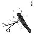
- FIGS. 7 a and 7 bshow the use of a pair of pointed pliers and how, by applying the force “F”, the bone ends can be brought together, according to a first alternative
- FIGS. 7 c and 7 dlikewise show the use of a said pair of pliers, however arranged differently, for applying said force “F”, according to a second alternative,
- FIGS. 7 e and 7 flikewise show, however in accordance with a third alternative, a preferred use of said pair of pliers for applying said force “F”,
- FIG. 8shows, after bringing the bone ends together and fixing them with an oblique screw joint, that said singly arranged screw is re-tightened and another screw, beyond the same, is screwed into the same bone end,
- FIG. 9shows a situation after a removal of the nails
- FIG. 10finally shows how, if preferred, an extra screw may be inserted through the slot where previously said single screw was slideably arranged.
- FIGS. 1 through 10the preferred embodiment of a device, according to the invention, is here shown used in a treatment sequence ( FIGS. 1 through 10 ) using a method according to the invention.
- the steps of said sequencewill in the following be described with reference to all parts involved.
- FIG. 1 aa section of a bone B is shown, which due to for instance a misalignment problem (as discussed above), is prone to be shortened.
- a fixation device 1is arranged, here arranged parallel to, above and adjacent to said bone section or portion B.
- FIGS. 1 b and 1 cshow a specific part having cavities 13 a and 13 b .
- the countersink made in the cavity 13 abeing provided with a slight slant to provide for a relatively easily handled screw joint, which is important for practical reasons after having performed a saw cut (see below).
- FIG. 2shows that the fixation device 1 has been brought into close contact with a surface of the bone portion B.
- four screws 2 , 2 ′are used, on the one hand in a set of three screws 2 , and on the other hand in a set of one separated screw 2 ′ and two nails 3 , each nail 3 shown in the vicinity of its related cavity 5 .
- Cavities or holes 4are arranged and adapted for the first set of three nails 2 and a cavity or a slot 13 a is adapted for said separated nail 2 ′. Between these sets 2 ; 3 , 2 ′ are said cavities 5 and adjacent said slot 13 a is a further hole or slot 13 b.
- the two nails 3are as shown aimed to be arranged in said cavities 5 , which probably best can be described as elongated slots in said fixation device 1 , the purpose of which will be described more in detail below.
- the cavity 13 a for the separated screw 2 ′is, as previously mentioned, designed in an elongated fashion.
- each of the three screws 2 , and the separated screw 2 ′ shown in FIG. 2have been finally tightened and fixed as well as each of the nails 3 have been driven into a position in which they are tightly fixed to cortex of the bone B.
- said fixation device 1includes two holes 6 , which are arranged transversely to each axis of the holes or cavities 4 , 5 and 13 a of said device.
- the holes 6are aimed for a temporary coaction with an arrangement formed as a cutting guide 7 , which, here shown at a distance from the fixation device 1 , is provided with guiding slots 8 for a saw blade.
- FIG. 4shows the fixation device 1 and the cutting guide 7 in coaction together with a saw blade 9 , for excising an excessive part of the bone section or portion B shown.
- FIG. 5shows the excision operation completed with an excised bone portion 10 as a separated part and with the saw blade 9 in its final position.
- FIG. 6in turn shows how, after excision of the excessive bone portion 10 , both bone end surfaces 11 and 11 ′ thus created are pushed together by applying a force F, however this may be done only after a temporarily release of the screw 2 ′ (illustrated by an arrow) in its elongated and slantedly designed hole 13 a.
- the bone end surfaces 11 and 11 ′are to be fixed in relation to each other and this is done by using an additional screw 12 , which is obliquely arranged in relation to a main direction of the bone, however transversely arranged to each of the bone end surfaces 11 and 11 ′ thus created.
- FIGS. 7 a through 7 fthree different alternatives are illustrated in order to exemplify how to bring the bone ends 11 and 11 ′ together.
- one leg 20 in the pair of pliers Pis attached to one of the holes 6 for the cutting guide 7 discussed above.
- More precisely one legis arranged in the one of the holes 6 situated most close to a cavity or a hole 12 a for the screw 12 to be obliquely arranged relative to said axis of the bone B.
- the leg 21 ais applied behind the two nails 3 to enable the bone end surfaces 11 and 11 ′ to be forced together, while according to FIGS. 7 c and 7 d said leg 21 b is hooked around the screw 2 ′, arranged in the cavity 13 a after the same has been suitably loosened as shown.
- said leg 21 c of the pair of pliersis hooked around an additional nail 22 , fixed to the side of the bone cortex for this purpose only.
- the pliers and associated legsare used in a manner so as to press the bone ends 11 and 11 ′ together. After so doing, the pressure of the pliers is upheld while the separated screw 2 ′ in the cavity 13 a is tightened.
- the specific design of the elongated cavity 13 athen makes the achieved position for the slided bone ends 11 and 11 ′ automatically to lock itself in that position.
- FIG. 8shows the finally united bone end surfaces 11 and 11 ′, between which the osteotomy has been performed, and how the bone end surfaces 11 and 11 ′ just have been secured together by making use of said screw 12 as well as of retightening the screw 2 ′ in the hole or cavity 13 a.
- FIG. 9shows the bone portion B and the device 1 in their final relative positions except for the alternative shown in FIG. 10 , where a further screw 2 ′′′ is arranged in an opposite end of the elongated slot or hole 13 a.
- the fixation device 1includes a recess 16 , which is supposed to be placed facing the part of the bone to be excised during the osteotomy operation.
- the purpose of the recess 16is on the one hand to provide a space in connection to the healing zone, not to cause interference where not needed between natural tissue such as the bone and the fixation device, and on the other hand to make sure that later on, when looking at the healing zone with the aid of X-ray methods, provide for best possible visibility of the healing-zone.
- the bone on which the osteotomy is to be performedlies relatively open and free to the surgeon.
- the device 1is applied to the surface of the bone portion B just above the area where the excision is to be made. Holes in a dimension suitable for the screws 2 to be used are drilled, using the holes 4 as a template, whereupon said device 1 is fixed to the bone surface by said set of three screws 2 .
- the device 1In using the device 1 as a template for drilling purposes it may prove useful to apply a clamp (not shown) around the bone B and the device 1 , in order to initially be able to properly fix the device 1 in relation to the bone B.
- a clamp(not shown) around the bone B and the device 1 , in order to initially be able to properly fix the device 1 in relation to the bone B.
- the holes 6are arranged mainly for one purpose only, namely for the attachment of the cutting guide 7 .
- FIGS. 3 and 4show how this attachment is preferred and how the saw blade 9 is applied.
- FIG. 4At reference numeral 17 in FIG. 4 is shown a number of alternative slots 8 adapted to indicate where to place a first cut, and at reference numeral 18 is also shown a slot where to always make the last cut in order to excise a suitable bone portion 10 .
- the excessive bone part 10is removed and as is shown in FIG. 6 , after slightly releasing the screw 2 ′ in the cavity 13 a , the bone end surfaces 11 and 11 ′ thus created are forced together by applying said force F as is shown in FIGS. 6 and 7 a through 7 f .
- the thus temporarily loosened bone portionaccording to FIGS. 7 a through 7 f , is forced into contact with its counterpart with fully coinciding bone end surfaces 11 and 11 ′.
- the movement of the temporarily slightly released bone portionis controlled rotationally by the nails 3 , which are not to be removed until the device 1 later on is finally fixed in situ, and in relation to the device 1 via the screw 2 ′ in the hole 13 a.
- a hole of a dimension suitable for fixing the screw 12 thereinis drilled with the cavity or hole 12 a as a template.
- the screw 12is thereafter fitted to keep the bone ends 11 and 11 ′ together.
- the screw 2 ′ in the cavity 13 ais retightened and another screw 2 ′′ is in a fashion as described above fitted to a drilled hole, using the cavity 13 b as a template.
- a screw 2 ′′is fitted to a hole drilled through the cavity 13 b at the distal end of the device 1 .
- an extra screw 2 ′′′may be attached to the elongated cavity 13 a in order to achieve an enhanced compression of the osteotomy.
Landscapes
- Health & Medical Sciences (AREA)
- Surgery (AREA)
- Orthopedic Medicine & Surgery (AREA)
- Life Sciences & Earth Sciences (AREA)
- Heart & Thoracic Surgery (AREA)
- Veterinary Medicine (AREA)
- Engineering & Computer Science (AREA)
- Biomedical Technology (AREA)
- Nuclear Medicine, Radiotherapy & Molecular Imaging (AREA)
- Medical Informatics (AREA)
- Molecular Biology (AREA)
- Animal Behavior & Ethology (AREA)
- General Health & Medical Sciences (AREA)
- Public Health (AREA)
- Oral & Maxillofacial Surgery (AREA)
- Dentistry (AREA)
- Neurology (AREA)
- Surgical Instruments (AREA)
Abstract
Description
- (1) Complete excision of the distal end of the ulna,
- (2) Partial excision of the distal end of the ulna,
- (3) Excision of the ulna and replacement with a prosthetic joint,
- (4) Fusion between the radius and the ulna with excision of a segment proximal to the fused joint to create a false joint, and
- (5) Shortening of the ulna.
Claims (6)
Priority Applications (1)
| Application Number | Priority Date | Filing Date | Title |
|---|---|---|---|
| US10/854,892US7540874B2 (en) | 2004-05-27 | 2004-05-27 | Method and device for use in osteotomy |
Applications Claiming Priority (1)
| Application Number | Priority Date | Filing Date | Title |
|---|---|---|---|
| US10/854,892US7540874B2 (en) | 2004-05-27 | 2004-05-27 | Method and device for use in osteotomy |
Publications (2)
| Publication Number | Publication Date |
|---|---|
| US20050277941A1 US20050277941A1 (en) | 2005-12-15 |
| US7540874B2true US7540874B2 (en) | 2009-06-02 |
Family
ID=35461478
Family Applications (1)
| Application Number | Title | Priority Date | Filing Date |
|---|---|---|---|
| US10/854,892Expired - LifetimeUS7540874B2 (en) | 2004-05-27 | 2004-05-27 | Method and device for use in osteotomy |
Country Status (1)
| Country | Link |
|---|---|
| US (1) | US7540874B2 (en) |
Cited By (50)
| Publication number | Priority date | Publication date | Assignee | Title |
|---|---|---|---|---|
| US20050177173A1 (en)* | 1998-10-02 | 2005-08-11 | Max Aebi | Spinal disc space distractor |
| US20120123484A1 (en)* | 2010-03-04 | 2012-05-17 | Eva Lietz | Ulna Osteotomy System |
| WO2014043370A1 (en)* | 2012-09-12 | 2014-03-20 | Nextremity Solutions, Inc. | Bone shortening device and method |
| US20140214090A1 (en)* | 2010-04-27 | 2014-07-31 | DePuy Synthes Products, LLC | Bone fixation systems and methods of use |
| US9597130B2 (en) | 2010-04-27 | 2017-03-21 | DePuy Synthes Products, Inc. | Bone fixation system including K-wire compression |
| RU2614882C1 (en)* | 2016-01-21 | 2017-03-30 | Государственное бюджетное образовательное учреждение высшего профессионального образования "Дагестанская государственная медицинская академия" Министерства здравоохранения РФ | Method for autoplasty of false joints of tubular bones |
| US20180193151A1 (en)* | 2015-07-02 | 2018-07-12 | First Ray, LLC | Orthopedic fasterners, instruments and methods |
| US10292713B2 (en) | 2015-01-28 | 2019-05-21 | First Ray, LLC | Freeform tri-planar osteotomy guide and method |
| US10376268B2 (en) | 2015-02-19 | 2019-08-13 | First Ray, LLC | Indexed tri-planar osteotomy guide and method |
| US10441329B2 (en) | 2013-10-28 | 2019-10-15 | Jace Medical, Llc | Orthopedic fixation device, system and method |
| US10512470B1 (en) | 2016-08-26 | 2019-12-24 | Treace Medical Concepts, Inc. | Osteotomy procedure for correcting bone misalignment |
| US10524808B1 (en) | 2016-11-11 | 2020-01-07 | Treace Medical Concepts, Inc. | Devices and techniques for performing an osteotomy procedure on a first metatarsal to correct a bone misalignment |
| US10555757B2 (en) | 2014-07-15 | 2020-02-11 | Treace Medical Concepts, Inc. | Bone positioning and cutting system and method |
| US10561426B1 (en) | 2015-01-07 | 2020-02-18 | Treace Medical Concepts, Inc. | Bone cutting guide systems and methods |
| US10575862B2 (en) | 2015-09-18 | 2020-03-03 | Treace Medical Concepts, Inc. | Joint spacer systems and methods |
| US10849663B2 (en) | 2015-07-14 | 2020-12-01 | Treace Medical Concepts, Inc. | Bone cutting guide systems and methods |
| US10849670B2 (en) | 2015-08-14 | 2020-12-01 | Treace Medical Concepts, Inc. | Bone positioning and preparing guide systems and methods |
| US10849631B2 (en) | 2015-02-18 | 2020-12-01 | Treace Medical Concepts, Inc. | Pivotable bone cutting guide useful for bone realignment and compression techniques |
| US10874446B2 (en) | 2015-07-14 | 2020-12-29 | Treace Medical Concepts, Inc. | Bone positioning guide |
| US10898211B2 (en) | 2015-01-14 | 2021-01-26 | Crossroads Extremity Systems, Llc | Opening and closing wedge osteotomy guide and method |
| US11026698B2 (en) | 2019-10-29 | 2021-06-08 | Skeletal Dynamics, Inc. | Osteotomy system and method of use |
| US20210322072A1 (en)* | 2013-03-15 | 2021-10-21 | Barry M. Fell | Bone repair system, kit and method |
| US11266449B2 (en)* | 2017-12-19 | 2022-03-08 | Orthopediatrics Corp | Osteotomy device and methods |
| US11278337B2 (en) | 2015-08-14 | 2022-03-22 | Treace Medical Concepts, Inc. | Tarsal-metatarsal joint procedure utilizing fulcrum |
| US11304735B2 (en) | 2020-02-19 | 2022-04-19 | Crossroads Extremity Systems, Llc | Systems and methods for Lapidus repair of bunions |
| US11413081B2 (en) | 2015-08-14 | 2022-08-16 | Treace Medical Concepts, Inc. | Tarsal-metatarsal joint procedure utilizing fulcrum |
| US11457931B1 (en) | 2021-03-31 | 2022-10-04 | Avanti Orthopaedics Llc | Bone shortening osteotomy apparatus |
| US11583323B2 (en) | 2018-07-12 | 2023-02-21 | Treace Medical Concepts, Inc. | Multi-diameter bone pin for installing and aligning bone fixation plate while minimizing bone damage |
| US11596443B2 (en) | 2018-07-11 | 2023-03-07 | Treace Medical Concepts, Inc. | Compressor-distractor for angularly realigning bone portions |
| US11607250B2 (en) | 2019-02-13 | 2023-03-21 | Treace Medical Concepts, Inc. | Tarsal-metatarsal joint procedure utilizing compressor-distractor and instrument providing sliding surface |
| US11622797B2 (en) | 2020-01-31 | 2023-04-11 | Treace Medical Concepts, Inc. | Metatarsophalangeal joint preparation and metatarsal realignment for fusion |
| US11627954B2 (en) | 2019-08-07 | 2023-04-18 | Treace Medical Concepts, Inc. | Bi-planar instrument for bone cutting and joint realignment procedure |
| USD1011524S1 (en) | 2022-02-23 | 2024-01-16 | Treace Medical Concepts, Inc. | Compressor-distractor for the foot |
| US11890039B1 (en) | 2019-09-13 | 2024-02-06 | Treace Medical Concepts, Inc. | Multi-diameter K-wire for orthopedic applications |
| US11889998B1 (en) | 2019-09-12 | 2024-02-06 | Treace Medical Concepts, Inc. | Surgical pin positioning lock |
| US11931106B2 (en) | 2019-09-13 | 2024-03-19 | Treace Medical Concepts, Inc. | Patient-specific surgical methods and instrumentation |
| US11986251B2 (en) | 2019-09-13 | 2024-05-21 | Treace Medical Concepts, Inc. | Patient-specific osteotomy instrumentation |
| US12004789B2 (en) | 2020-05-19 | 2024-06-11 | Treace Medical Concepts, Inc. | Devices and techniques for treating metatarsus adductus |
| USD1051382S1 (en) | 2022-02-23 | 2024-11-12 | Treace Medical Concepts, Inc. | Lesser metatarsal cut guide |
| US12161371B2 (en) | 2021-01-18 | 2024-12-10 | Treace Medical Concepts, Inc. | Contoured bone plate with locking screw for bone compression, particularly across a tarsometatarsal joint |
| US12185996B2 (en) | 2014-08-20 | 2025-01-07 | Biomet Microfixation, Llc | Implant positioning devices and methods |
| USD1057155S1 (en) | 2022-02-23 | 2025-01-07 | Treace Medical Concepts, Inc. | Lesser metatarsal cut guide with parallel cut faces |
| US12193683B2 (en) | 2021-05-20 | 2025-01-14 | Treace Medical Concepts, Inc. | Cut guide with integrated joint realignment features |
| USD1068077S1 (en) | 2023-02-08 | 2025-03-25 | Treace Medical Concepts, Inc. | Orthopedic rasp for preparing an intercuneiform joint |
| USD1068078S1 (en) | 2023-02-08 | 2025-03-25 | Treace Medical Concepts, Inc. | Handle for an orthopedic instrument |
| USD1075012S1 (en) | 2022-02-23 | 2025-05-13 | Treace Medical Concepts, Inc. | Metatarsal lateral release instrument |
| US12310603B2 (en) | 2021-02-18 | 2025-05-27 | Treace Medical Concepts, Inc. | System and technique for metatarsal realignment with reduced incision length |
| USD1079011S1 (en) | 2022-02-23 | 2025-06-10 | Treace Medical Concepts, Inc. | Metatarsal cut guide with parallel cut faces |
| US12403012B2 (en) | 2019-07-26 | 2025-09-02 | Crossroads Extremity Systems, Llc | Bone repositioning guide system and procedure |
| US12440250B2 (en) | 2024-02-05 | 2025-10-14 | Treace Medical Concepts, Inc. | Multi-diameter K-wire for orthopedic applications |
Families Citing this family (13)
| Publication number | Priority date | Publication date | Assignee | Title |
|---|---|---|---|---|
| US8652142B2 (en)* | 2006-04-28 | 2014-02-18 | Acumed Llc | Osteotomy systems |
| US20070276383A1 (en)* | 2006-05-11 | 2007-11-29 | Rayhack L.L.C. | Osteotomy system |
| US8282644B2 (en)* | 2007-01-17 | 2012-10-09 | Edwards Scott G | System and method for bone shortening |
| US20090254126A1 (en)* | 2008-04-04 | 2009-10-08 | Skeletal Dynamics Llc | Compression/distraction osteotomy system, plate, method, drill guide and saw guide |
| US8167891B2 (en)* | 2008-07-21 | 2012-05-01 | Osteomed Llc | System and method for fracture reduction |
| FR2936700B1 (en) | 2008-10-02 | 2012-04-13 | Memometal Technologies | ORTHOPEDIC IMPLANT IN THE FORM OF A PLATE TO BE FIXED BETWEEN TWO BONE PARTS |
| EP2179701B1 (en)* | 2008-10-23 | 2011-05-18 | Stryker Leibinger GmbH & Co. KG | Bone plate for use in a surgical procedure |
| AT506937B1 (en)* | 2008-11-27 | 2010-01-15 | I T S Gmbh | DEVICE FOR CONSTRUCTING A LONG BONE |
| US9011507B2 (en) | 2009-10-28 | 2015-04-21 | Orthopro Llc | Compression plate kit and methods for repairing bone discontinuities |
| US8162996B2 (en) | 2009-10-28 | 2012-04-24 | Orthopro Llc | Methods for repairing bone discontinuities |
| BE1021823B1 (en)* | 2014-02-26 | 2016-01-20 | Biomet Manufacturing, Llc | UTILITY FOR OSTEOTOMY |
| IT201700006369A1 (en)* | 2017-01-20 | 2018-07-20 | Orthofix Srl | Internal plate fixation device |
| WO2018223063A1 (en)* | 2017-06-01 | 2018-12-06 | Shawn Burke | Method and system for the reduction and fixation of bone segments |
Citations (38)
| Publication number | Priority date | Publication date | Assignee | Title |
|---|---|---|---|---|
| US1789060A (en)* | 1928-09-29 | 1931-01-13 | King Scheerer Corp | Bone-fracture clamp |
| US3244170A (en)* | 1962-11-23 | 1966-04-05 | Robert T Mcelvenny | Compression type bone splint |
| US3386437A (en)* | 1966-01-14 | 1968-06-04 | Richard Mfg Company | Compression device for use with a bone fracture plate |
| US3400711A (en)* | 1965-01-16 | 1968-09-10 | Fur Feinmechanik Vormals Jette | Surgical bone plating appliance |
| US4119092A (en)* | 1976-04-21 | 1978-10-10 | Gil Jose Luis | Methods of reduction of bone fractures |
| US4187841A (en)* | 1978-07-07 | 1980-02-12 | Knutson Richard A | Bone compression or distraction device |
| US4570625A (en)* | 1981-08-06 | 1986-02-18 | National Research Development Corporation | Apparatus for external fixation of bone fractures |
| US4929247A (en) | 1988-10-06 | 1990-05-29 | Rayhack John M | Bone compression and distraction device |
| US5042983A (en) | 1989-10-30 | 1991-08-27 | Rayhack John M | Precision bone cutting guide |
| US5129903A (en)* | 1988-06-18 | 1992-07-14 | Luhr Hans Georg | Bone plate |
| US5167665A (en)* | 1991-12-31 | 1992-12-01 | Mckinney William W | Method of attaching objects to bone |
| US5176685A (en)* | 1989-10-30 | 1993-01-05 | Rayhack John M | Precision bone cutting guide |
| US5234434A (en)* | 1992-08-17 | 1993-08-10 | Marlowe Goble E | Mutliple guide sleeve drill guide |
| US5275599A (en)* | 1986-08-11 | 1994-01-04 | Zbikowski Juan L | Biocompression external fixator for osteosynthesis |
| US5352228A (en)* | 1993-05-10 | 1994-10-04 | Kummer Frederick J | Apparatus and method to provide compression for a locked intramedullary nail |
| FR2705881A1 (en) | 1993-06-01 | 1994-12-09 | Hardy Jean Marie | Support rail for filling in loss of bone substance |
| US5662649A (en)* | 1995-02-15 | 1997-09-02 | Huebner; Randall J. | External fixator for repairing fractures of distal radius and wrist |
| US5749873A (en)* | 1993-11-26 | 1998-05-12 | Fairley; Jeffrey D. | Apparatus for the mobile fixation of bones |
| US5902304A (en)* | 1995-12-01 | 1999-05-11 | Walker; David A. | Telescopic bone plate for use in bone lengthening by distraction osteogenesis |
| US5951557A (en)* | 1997-12-30 | 1999-09-14 | Luter; Dennis W. | Bone plate |
| US5964763A (en)* | 1997-02-14 | 1999-10-12 | Incavo; Stephen J. | Incrementally adjustable tibial osteotomy fixation device and method |
| US5973223A (en)* | 1994-02-21 | 1999-10-26 | Collux Ab | Implant for fixing femoral fractures |
| US5976138A (en)* | 1997-02-28 | 1999-11-02 | Baumgart; Rainer | Distraction system for long bones |
| US6007535A (en) | 1996-01-03 | 1999-12-28 | John M. Rayhack | Multi-plane bone distraction system |
| US6027504A (en)* | 1996-12-06 | 2000-02-22 | Mcguire; David A. | Device and method for producing osteotomies |
| US6066142A (en)* | 1998-10-22 | 2000-05-23 | Depuy Orthopaedics, Inc. | Variable position bone drilling alignment guide |
| US6183475B1 (en)* | 1998-12-18 | 2001-02-06 | Sulzer Orthopedics Inc. | Distal femoral osteotomy system and method |
| RU2183435C2 (en) | 2000-07-26 | 2002-06-20 | Научно-исследовательский центр Татарстана "Восстановительная травматология и ортопедия" | Device for making reposition and osteosynthesis of forearm bones |
| US20020143335A1 (en)* | 2001-03-30 | 2002-10-03 | Von Hoffmann Gerard | Distal bone anchors for bone fixation with secondary compression |
| US6678562B1 (en)* | 2000-01-12 | 2004-01-13 | Amei Technologies Inc. | Combined tissue/bone growth stimulator and external fixation device |
| US20050090900A1 (en)* | 2003-10-22 | 2005-04-28 | Nordquist William D. | Implantable brace for a fracture and methods |
| US20060200134A1 (en)* | 2002-02-01 | 2006-09-07 | James Freid | Spinal plate system for stabilizing a portion of a spine |
| US7182766B1 (en)* | 2003-08-08 | 2007-02-27 | Stuart Mogul | Adjustable osteotomy guide |
| US7189237B2 (en)* | 2002-11-19 | 2007-03-13 | Acumed Llc | Deformable bone plates |
| US20070270850A1 (en)* | 2006-04-28 | 2007-11-22 | Geissler William B | Osteotomy systems |
| US7326212B2 (en)* | 2002-11-19 | 2008-02-05 | Acumed Llc | Bone plates with reference marks |
| US7425213B2 (en)* | 2002-12-10 | 2008-09-16 | Depuy Products, Inc. | Method of endosteal nailing |
| US20080275451A1 (en)* | 2007-05-04 | 2008-11-06 | Mcallister Craig M | Distal femoral cutting guide |
- 2004
- 2004-05-27USUS10/854,892patent/US7540874B2/ennot_activeExpired - Lifetime
Patent Citations (38)
| Publication number | Priority date | Publication date | Assignee | Title |
|---|---|---|---|---|
| US1789060A (en)* | 1928-09-29 | 1931-01-13 | King Scheerer Corp | Bone-fracture clamp |
| US3244170A (en)* | 1962-11-23 | 1966-04-05 | Robert T Mcelvenny | Compression type bone splint |
| US3400711A (en)* | 1965-01-16 | 1968-09-10 | Fur Feinmechanik Vormals Jette | Surgical bone plating appliance |
| US3386437A (en)* | 1966-01-14 | 1968-06-04 | Richard Mfg Company | Compression device for use with a bone fracture plate |
| US4119092A (en)* | 1976-04-21 | 1978-10-10 | Gil Jose Luis | Methods of reduction of bone fractures |
| US4187841A (en)* | 1978-07-07 | 1980-02-12 | Knutson Richard A | Bone compression or distraction device |
| US4570625A (en)* | 1981-08-06 | 1986-02-18 | National Research Development Corporation | Apparatus for external fixation of bone fractures |
| US5275599A (en)* | 1986-08-11 | 1994-01-04 | Zbikowski Juan L | Biocompression external fixator for osteosynthesis |
| US5129903A (en)* | 1988-06-18 | 1992-07-14 | Luhr Hans Georg | Bone plate |
| US4929247A (en) | 1988-10-06 | 1990-05-29 | Rayhack John M | Bone compression and distraction device |
| US5042983A (en) | 1989-10-30 | 1991-08-27 | Rayhack John M | Precision bone cutting guide |
| US5176685A (en)* | 1989-10-30 | 1993-01-05 | Rayhack John M | Precision bone cutting guide |
| US5167665A (en)* | 1991-12-31 | 1992-12-01 | Mckinney William W | Method of attaching objects to bone |
| US5234434A (en)* | 1992-08-17 | 1993-08-10 | Marlowe Goble E | Mutliple guide sleeve drill guide |
| US5352228A (en)* | 1993-05-10 | 1994-10-04 | Kummer Frederick J | Apparatus and method to provide compression for a locked intramedullary nail |
| FR2705881A1 (en) | 1993-06-01 | 1994-12-09 | Hardy Jean Marie | Support rail for filling in loss of bone substance |
| US5749873A (en)* | 1993-11-26 | 1998-05-12 | Fairley; Jeffrey D. | Apparatus for the mobile fixation of bones |
| US5973223A (en)* | 1994-02-21 | 1999-10-26 | Collux Ab | Implant for fixing femoral fractures |
| US5662649A (en)* | 1995-02-15 | 1997-09-02 | Huebner; Randall J. | External fixator for repairing fractures of distal radius and wrist |
| US5902304A (en)* | 1995-12-01 | 1999-05-11 | Walker; David A. | Telescopic bone plate for use in bone lengthening by distraction osteogenesis |
| US6007535A (en) | 1996-01-03 | 1999-12-28 | John M. Rayhack | Multi-plane bone distraction system |
| US6027504A (en)* | 1996-12-06 | 2000-02-22 | Mcguire; David A. | Device and method for producing osteotomies |
| US5964763A (en)* | 1997-02-14 | 1999-10-12 | Incavo; Stephen J. | Incrementally adjustable tibial osteotomy fixation device and method |
| US5976138A (en)* | 1997-02-28 | 1999-11-02 | Baumgart; Rainer | Distraction system for long bones |
| US5951557A (en)* | 1997-12-30 | 1999-09-14 | Luter; Dennis W. | Bone plate |
| US6066142A (en)* | 1998-10-22 | 2000-05-23 | Depuy Orthopaedics, Inc. | Variable position bone drilling alignment guide |
| US6183475B1 (en)* | 1998-12-18 | 2001-02-06 | Sulzer Orthopedics Inc. | Distal femoral osteotomy system and method |
| US6678562B1 (en)* | 2000-01-12 | 2004-01-13 | Amei Technologies Inc. | Combined tissue/bone growth stimulator and external fixation device |
| RU2183435C2 (en) | 2000-07-26 | 2002-06-20 | Научно-исследовательский центр Татарстана "Восстановительная травматология и ортопедия" | Device for making reposition and osteosynthesis of forearm bones |
| US20020143335A1 (en)* | 2001-03-30 | 2002-10-03 | Von Hoffmann Gerard | Distal bone anchors for bone fixation with secondary compression |
| US20060200134A1 (en)* | 2002-02-01 | 2006-09-07 | James Freid | Spinal plate system for stabilizing a portion of a spine |
| US7189237B2 (en)* | 2002-11-19 | 2007-03-13 | Acumed Llc | Deformable bone plates |
| US7326212B2 (en)* | 2002-11-19 | 2008-02-05 | Acumed Llc | Bone plates with reference marks |
| US7425213B2 (en)* | 2002-12-10 | 2008-09-16 | Depuy Products, Inc. | Method of endosteal nailing |
| US7182766B1 (en)* | 2003-08-08 | 2007-02-27 | Stuart Mogul | Adjustable osteotomy guide |
| US20050090900A1 (en)* | 2003-10-22 | 2005-04-28 | Nordquist William D. | Implantable brace for a fracture and methods |
| US20070270850A1 (en)* | 2006-04-28 | 2007-11-22 | Geissler William B | Osteotomy systems |
| US20080275451A1 (en)* | 2007-05-04 | 2008-11-06 | Mcallister Craig M | Distal femoral cutting guide |
Non-Patent Citations (1)
| Title |
|---|
| Rayhack J.M., Gasser S.I., Latta L.L., Ouellette E.A., Milne E.L., "Precision oblique osteotomy for shortening of the ulna", J Hand Surg [Am]. Sep. 1993;18(5):908 (from Medline). |
Cited By (103)
| Publication number | Priority date | Publication date | Assignee | Title |
|---|---|---|---|---|
| US20050177173A1 (en)* | 1998-10-02 | 2005-08-11 | Max Aebi | Spinal disc space distractor |
| US20120123484A1 (en)* | 2010-03-04 | 2012-05-17 | Eva Lietz | Ulna Osteotomy System |
| US9023052B2 (en)* | 2010-03-04 | 2015-05-05 | DePuy Synthes Products, Inc. | Ulna osteotomy system |
| US20140214090A1 (en)* | 2010-04-27 | 2014-07-31 | DePuy Synthes Products, LLC | Bone fixation systems and methods of use |
| US9113969B2 (en)* | 2010-04-27 | 2015-08-25 | DePuy Synthes Products, Inc. | Bone fixation systems and methods of use |
| US9597130B2 (en) | 2010-04-27 | 2017-03-21 | DePuy Synthes Products, Inc. | Bone fixation system including K-wire compression |
| US10631902B2 (en) | 2012-09-12 | 2020-04-28 | Nextremity Solutions, Inc. | Bone shortening device and method |
| WO2014043370A1 (en)* | 2012-09-12 | 2014-03-20 | Nextremity Solutions, Inc. | Bone shortening device and method |
| US20210322072A1 (en)* | 2013-03-15 | 2021-10-21 | Barry M. Fell | Bone repair system, kit and method |
| US11737799B2 (en)* | 2013-03-15 | 2023-08-29 | The Penn State Research Foundation | Bone repair system, kit and method |
| US11344345B2 (en) | 2013-10-28 | 2022-05-31 | Jace Medical, Llc | Orthopaedic fixation device, system and method |
| US10441329B2 (en) | 2013-10-28 | 2019-10-15 | Jace Medical, Llc | Orthopedic fixation device, system and method |
| US11759242B2 (en) | 2013-10-28 | 2023-09-19 | Jace Medical, Llc | Orthopaedic fixation device, system and method |
| US12178482B2 (en) | 2013-10-28 | 2024-12-31 | Biomet Microfixation, Llc | Orthopaedic fixation devices, systems and methods |
| US11147590B2 (en) | 2014-07-15 | 2021-10-19 | Treace Medical Concepts, Inc. | Bone positioning and cutting system and method |
| US10555757B2 (en) | 2014-07-15 | 2020-02-11 | Treace Medical Concepts, Inc. | Bone positioning and cutting system and method |
| US11523845B2 (en) | 2014-07-15 | 2022-12-13 | Treace Medical Concepts, Inc. | Bone positioning and cutting system and method |
| US11771467B2 (en) | 2014-07-15 | 2023-10-03 | Treace Medical Concepts, Inc. | Bone positioning and cutting system and method |
| US10945764B2 (en) | 2014-07-15 | 2021-03-16 | Treace Medical Concepts, Inc. | Bone positioning and cutting system and method |
| US11497528B2 (en) | 2014-07-15 | 2022-11-15 | Treace Medical Concepts, Inc. | Bone positioning and cutting system and method |
| US12349941B2 (en) | 2014-07-15 | 2025-07-08 | Treace Medical Concepts, Inc. | Bone positioning and cutting system and method |
| US11937849B2 (en) | 2014-07-15 | 2024-03-26 | Treace Medical Concepts, Inc. | Bone positioning and cutting system and method |
| US12185996B2 (en) | 2014-08-20 | 2025-01-07 | Biomet Microfixation, Llc | Implant positioning devices and methods |
| US10603046B2 (en) | 2015-01-07 | 2020-03-31 | Treace Medical Concepts, Inc. | Bone cutting guide systems and methods |
| US10561426B1 (en) | 2015-01-07 | 2020-02-18 | Treace Medical Concepts, Inc. | Bone cutting guide systems and methods |
| US10888335B2 (en) | 2015-01-07 | 2021-01-12 | Treace Medical Concepts, Inc. | Bone cutting guide systems and methods |
| US11786257B2 (en) | 2015-01-07 | 2023-10-17 | Treace Medical Concepts, Inc. | Bone cutting guide systems and methods |
| US12268397B2 (en) | 2015-01-07 | 2025-04-08 | Treace Medical Concepts, Inc. | Bone cutting guide systems and methods |
| US10898211B2 (en) | 2015-01-14 | 2021-01-26 | Crossroads Extremity Systems, Llc | Opening and closing wedge osteotomy guide and method |
| US11160567B2 (en) | 2015-01-14 | 2021-11-02 | Crossroads Extremity Systems, Llc | Opening and closing wedge osteotomy guide and method |
| US11974760B2 (en) | 2015-01-14 | 2024-05-07 | Crossroads Extremity Systems, Llc | Opening and closing wedge osteotomy guide and method |
| US11478254B2 (en) | 2015-01-28 | 2022-10-25 | Crossroads Extremity Systems, Llc | Freeform tri-planar osteotomy guide and method |
| US11259817B2 (en) | 2015-01-28 | 2022-03-01 | Crossroads Extremity Systems, Llc | Freeform tri-planar osteotomy guide and method |
| US10292713B2 (en) | 2015-01-28 | 2019-05-21 | First Ray, LLC | Freeform tri-planar osteotomy guide and method |
| US11510685B2 (en) | 2015-01-28 | 2022-11-29 | Crossroads Extremity Systems, Llc | Freeform tri-planar osteotomy guide and method |
| US11844533B2 (en) | 2015-02-18 | 2023-12-19 | Treace Medical Concepts, Inc. | Pivotable bone cutting guide useful for bone realignment and compression techniques |
| US10849631B2 (en) | 2015-02-18 | 2020-12-01 | Treace Medical Concepts, Inc. | Pivotable bone cutting guide useful for bone realignment and compression techniques |
| US10376268B2 (en) | 2015-02-19 | 2019-08-13 | First Ray, LLC | Indexed tri-planar osteotomy guide and method |
| US11304705B2 (en) | 2015-02-19 | 2022-04-19 | Crossroads Extremity Systems, Llc | Indexed tri-planar osteotomy guide and method |
| US10743995B2 (en)* | 2015-07-02 | 2020-08-18 | First Ray, LLC | Orthopedic fasterners, instruments and methods |
| US20180193151A1 (en)* | 2015-07-02 | 2018-07-12 | First Ray, LLC | Orthopedic fasterners, instruments and methods |
| US11950819B2 (en) | 2015-07-14 | 2024-04-09 | Treace Medical Concepts, Inc. | Bone positioning guide |
| US11185359B2 (en) | 2015-07-14 | 2021-11-30 | Treace Medical Concepts, Inc. | Bone positioning guide |
| US11116558B2 (en) | 2015-07-14 | 2021-09-14 | Treace Medical Concepts, Inc. | Bone positioning guide |
| US10849663B2 (en) | 2015-07-14 | 2020-12-01 | Treace Medical Concepts, Inc. | Bone cutting guide systems and methods |
| US11963703B2 (en) | 2015-07-14 | 2024-04-23 | Treace Medical Concepts, Inc. | Bone cutting guide systems and methods |
| US12102368B2 (en) | 2015-07-14 | 2024-10-01 | Treace Medical Concepts, Inc. | Bone positioning guide |
| US11602386B2 (en) | 2015-07-14 | 2023-03-14 | Treace Medical Concepts, Inc. | Bone positioning guide |
| US10874446B2 (en) | 2015-07-14 | 2020-12-29 | Treace Medical Concepts, Inc. | Bone positioning guide |
| US11602387B2 (en) | 2015-08-14 | 2023-03-14 | Treace Medical Concepts, Inc. | Bone positioning and preparing guide systems and methods |
| US11413081B2 (en) | 2015-08-14 | 2022-08-16 | Treace Medical Concepts, Inc. | Tarsal-metatarsal joint procedure utilizing fulcrum |
| US11039873B2 (en) | 2015-08-14 | 2021-06-22 | Treace Medical Concepts, Inc. | Bone positioning and preparing guide systems and methods |
| US11213333B2 (en) | 2015-08-14 | 2022-01-04 | Treace Medical Concepts, Inc. | Bone positioning and preparing guide systems and methods |
| US12274481B2 (en) | 2015-08-14 | 2025-04-15 | Treace Medical Concepts, Inc. | Bone positioning and preparing guide systems and methods |
| US11278337B2 (en) | 2015-08-14 | 2022-03-22 | Treace Medical Concepts, Inc. | Tarsal-metatarsal joint procedure utilizing fulcrum |
| US11911085B2 (en) | 2015-08-14 | 2024-02-27 | Treace Medical Concepts, Inc. | Bone positioning and preparing guide systems and methods |
| US12268428B2 (en) | 2015-08-14 | 2025-04-08 | Treace Medical Concepts, Inc. | Tarsal-metatarsal joint procedure utilizing fulcrum |
| US10849670B2 (en) | 2015-08-14 | 2020-12-01 | Treace Medical Concepts, Inc. | Bone positioning and preparing guide systems and methods |
| US11690659B2 (en) | 2015-08-14 | 2023-07-04 | Treace Medical Concepts, Inc. | Tarsal-metatarsal joint procedure utilizing fulcrum |
| US11648019B2 (en) | 2015-09-18 | 2023-05-16 | Treace Medical Concepts, Inc. | Joint spacer systems and methods |
| US12349927B2 (en) | 2015-09-18 | 2025-07-08 | Treace Medical Concepts, Inc. | Joint spacer systems and methods |
| US10575862B2 (en) | 2015-09-18 | 2020-03-03 | Treace Medical Concepts, Inc. | Joint spacer systems and methods |
| US11771443B2 (en) | 2015-09-18 | 2023-10-03 | Treace Medical Concepts, Inc. | Joint spacer systems and methods |
| RU2614882C1 (en)* | 2016-01-21 | 2017-03-30 | Государственное бюджетное образовательное учреждение высшего профессионального образования "Дагестанская государственная медицинская академия" Министерства здравоохранения РФ | Method for autoplasty of false joints of tubular bones |
| US11931047B2 (en) | 2016-08-26 | 2024-03-19 | Treace Medical Concepts, Inc. | Osteotomy procedure for correcting bone misalignment |
| US10512470B1 (en) | 2016-08-26 | 2019-12-24 | Treace Medical Concepts, Inc. | Osteotomy procedure for correcting bone misalignment |
| US11076863B1 (en) | 2016-08-26 | 2021-08-03 | Treace Medical Concepts, Inc. | Osteotomy procedure for correcting bone misalignment |
| US10582936B1 (en) | 2016-11-11 | 2020-03-10 | Treace Medical Concepts, Inc. | Devices and techniques for performing an osteotomy procedure on a first metatarsal to correct a bone misalignment |
| US12414779B2 (en) | 2016-11-11 | 2025-09-16 | Treace Medical Concepts, Inc. | Devices and techniques for performing an osteotomy procedure on a first metatarsal to correct a bone misalignment |
| US11364037B2 (en) | 2016-11-11 | 2022-06-21 | Treace Medical Concepts, Inc. | Techniques for performing an osteotomy procedure on bone to correct a bone misalignment |
| US10524808B1 (en) | 2016-11-11 | 2020-01-07 | Treace Medical Concepts, Inc. | Devices and techniques for performing an osteotomy procedure on a first metatarsal to correct a bone misalignment |
| US11266449B2 (en)* | 2017-12-19 | 2022-03-08 | Orthopediatrics Corp | Osteotomy device and methods |
| US11596443B2 (en) | 2018-07-11 | 2023-03-07 | Treace Medical Concepts, Inc. | Compressor-distractor for angularly realigning bone portions |
| US11583323B2 (en) | 2018-07-12 | 2023-02-21 | Treace Medical Concepts, Inc. | Multi-diameter bone pin for installing and aligning bone fixation plate while minimizing bone damage |
| US12279794B2 (en) | 2019-02-13 | 2025-04-22 | Treace Medical Concepts, Inc. | Tarsal-metatarsal joint procedure utilizing compressor-distractor and instrument providing sliding surface |
| US11607250B2 (en) | 2019-02-13 | 2023-03-21 | Treace Medical Concepts, Inc. | Tarsal-metatarsal joint procedure utilizing compressor-distractor and instrument providing sliding surface |
| US12403012B2 (en) | 2019-07-26 | 2025-09-02 | Crossroads Extremity Systems, Llc | Bone repositioning guide system and procedure |
| US11627954B2 (en) | 2019-08-07 | 2023-04-18 | Treace Medical Concepts, Inc. | Bi-planar instrument for bone cutting and joint realignment procedure |
| US12251091B2 (en) | 2019-08-07 | 2025-03-18 | Treace Medical Concepts, Inc. | Bi-planar instrument for bone cutting and joint realignment procedure |
| US11889998B1 (en) | 2019-09-12 | 2024-02-06 | Treace Medical Concepts, Inc. | Surgical pin positioning lock |
| US11986251B2 (en) | 2019-09-13 | 2024-05-21 | Treace Medical Concepts, Inc. | Patient-specific osteotomy instrumentation |
| US11931106B2 (en) | 2019-09-13 | 2024-03-19 | Treace Medical Concepts, Inc. | Patient-specific surgical methods and instrumentation |
| US11890039B1 (en) | 2019-09-13 | 2024-02-06 | Treace Medical Concepts, Inc. | Multi-diameter K-wire for orthopedic applications |
| US11026698B2 (en) | 2019-10-29 | 2021-06-08 | Skeletal Dynamics, Inc. | Osteotomy system and method of use |
| US11701129B2 (en) | 2019-10-29 | 2023-07-18 | Skeletal Dynamics, Inc. | Osteotomy system and method of use |
| US11622797B2 (en) | 2020-01-31 | 2023-04-11 | Treace Medical Concepts, Inc. | Metatarsophalangeal joint preparation and metatarsal realignment for fusion |
| US12364522B2 (en) | 2020-01-31 | 2025-07-22 | Treace Medical Concepts, Inc. | Metatarsophalangeal joint preparation and metatarsal realignment for fusion |
| US11304735B2 (en) | 2020-02-19 | 2022-04-19 | Crossroads Extremity Systems, Llc | Systems and methods for Lapidus repair of bunions |
| US11779359B2 (en) | 2020-02-19 | 2023-10-10 | Crossroads Extremity Systems, Llc | Systems and methods for Lapidus repair of bunions |
| US12004789B2 (en) | 2020-05-19 | 2024-06-11 | Treace Medical Concepts, Inc. | Devices and techniques for treating metatarsus adductus |
| US12396770B2 (en) | 2020-05-19 | 2025-08-26 | Treace Medical Concepts, Inc. | Devices and techniques for treating metatarsus adductus |
| US12161371B2 (en) | 2021-01-18 | 2024-12-10 | Treace Medical Concepts, Inc. | Contoured bone plate with locking screw for bone compression, particularly across a tarsometatarsal joint |
| US12310603B2 (en) | 2021-02-18 | 2025-05-27 | Treace Medical Concepts, Inc. | System and technique for metatarsal realignment with reduced incision length |
| US11457931B1 (en) | 2021-03-31 | 2022-10-04 | Avanti Orthopaedics Llc | Bone shortening osteotomy apparatus |
| US12193683B2 (en) | 2021-05-20 | 2025-01-14 | Treace Medical Concepts, Inc. | Cut guide with integrated joint realignment features |
| USD1057155S1 (en) | 2022-02-23 | 2025-01-07 | Treace Medical Concepts, Inc. | Lesser metatarsal cut guide with parallel cut faces |
| USD1079011S1 (en) | 2022-02-23 | 2025-06-10 | Treace Medical Concepts, Inc. | Metatarsal cut guide with parallel cut faces |
| USD1011524S1 (en) | 2022-02-23 | 2024-01-16 | Treace Medical Concepts, Inc. | Compressor-distractor for the foot |
| USD1051382S1 (en) | 2022-02-23 | 2024-11-12 | Treace Medical Concepts, Inc. | Lesser metatarsal cut guide |
| USD1075012S1 (en) | 2022-02-23 | 2025-05-13 | Treace Medical Concepts, Inc. | Metatarsal lateral release instrument |
| USD1068078S1 (en) | 2023-02-08 | 2025-03-25 | Treace Medical Concepts, Inc. | Handle for an orthopedic instrument |
| USD1068077S1 (en) | 2023-02-08 | 2025-03-25 | Treace Medical Concepts, Inc. | Orthopedic rasp for preparing an intercuneiform joint |
| US12440250B2 (en) | 2024-02-05 | 2025-10-14 | Treace Medical Concepts, Inc. | Multi-diameter K-wire for orthopedic applications |
Also Published As
| Publication number | Publication date |
|---|---|
| US20050277941A1 (en) | 2005-12-15 |
Similar Documents
| Publication | Publication Date | Title |
|---|---|---|
| US7540874B2 (en) | Method and device for use in osteotomy | |
| US12396768B2 (en) | Intramedullary nail alignment guides, fixation guides, devices, systems, and methods of use | |
| JP6636025B2 (en) | Resection guide and plate for proximal bunion and method of use | |
| US9814474B2 (en) | Resection guides, implants and methods | |
| US10709457B2 (en) | High tibial osteotomy guide | |
| US6689139B2 (en) | Long oblique ulna shortening osteotomy jig | |
| US12251091B2 (en) | Bi-planar instrument for bone cutting and joint realignment procedure | |
| EP2670327B1 (en) | Bone defect repair device | |
| EP2938279B1 (en) | Alignment guide system | |
| US20040138669A1 (en) | Long oblique ulna shortening osteotomy jig | |
| US20100168799A1 (en) | Ulnar osteotomy plate including increased compression | |
| JP2011516150A (en) | Intramedullary instrument assembly and related methods | |
| EP3975881B1 (en) | Osteotomy device | |
| US10966735B1 (en) | Surgical device and method for performing arthrodesis |
Legal Events
| Date | Code | Title | Description |
|---|---|---|---|
| AS | Assignment | Owner name:TRIMED INC., CALIFORNIA Free format text:ASSIGNMENT OF ASSIGNORS INTEREST;ASSIGNOR:TRUMBLE, THOMAS E.;REEL/FRAME:015403/0506 Effective date:20040512 | |
| AS | Assignment | Owner name:TRIMED INC., CALIFORNIA Free format text:ASSIGNMENT OF ASSIGNORS INTEREST;ASSIGNOR:TELLMAN, LARS;REEL/FRAME:015403/0508 Effective date:20040512 | |
| FEPP | Fee payment procedure | Free format text:PAYOR NUMBER ASSIGNED (ORIGINAL EVENT CODE: ASPN); ENTITY STATUS OF PATENT OWNER: SMALL ENTITY | |
| STCF | Information on status: patent grant | Free format text:PATENTED CASE | |
| CC | Certificate of correction | ||
| FPAY | Fee payment | Year of fee payment:4 | |
| FPAY | Fee payment | Year of fee payment:8 | |
| MAFP | Maintenance fee payment | Free format text:PAYMENT OF MAINTENANCE FEE, 12TH YR, SMALL ENTITY (ORIGINAL EVENT CODE: M2553); ENTITY STATUS OF PATENT OWNER: SMALL ENTITY Year of fee payment:12 | |
| AS | Assignment | Owner name:TRIMED, INC., CALIFORNIA Free format text:CHANGE OF NAME;ASSIGNOR:TRIMED INC.;REEL/FRAME:068916/0799 Effective date:20240816 |