US7540846B2 - Energy application with inflatable annular lens - Google Patents
Energy application with inflatable annular lensDownload PDFInfo
- Publication number
- US7540846B2 US7540846B2US11/267,123US26712305AUS7540846B2US 7540846 B2US7540846 B2US 7540846B2US 26712305 AUS26712305 AUS 26712305AUS 7540846 B2US7540846 B2US 7540846B2
- Authority
- US
- United States
- Prior art keywords
- lens
- emitter
- balloon
- central axis
- ultrasonic energy
- Prior art date
- Legal status (The legal status is an assumption and is not a legal conclusion. Google has not performed a legal analysis and makes no representation as to the accuracy of the status listed.)
- Expired - Lifetime, expires
Links
Images


Classifications
- A—HUMAN NECESSITIES
- A61—MEDICAL OR VETERINARY SCIENCE; HYGIENE
- A61B—DIAGNOSIS; SURGERY; IDENTIFICATION
- A61B17/00—Surgical instruments, devices or methods
- A61B17/22—Implements for squeezing-off ulcers or the like on inner organs of the body; Implements for scraping-out cavities of body organs, e.g. bones; for invasive removal or destruction of calculus using mechanical vibrations; for removing obstructions in blood vessels, not otherwise provided for
- A61B17/22004—Implements for squeezing-off ulcers or the like on inner organs of the body; Implements for scraping-out cavities of body organs, e.g. bones; for invasive removal or destruction of calculus using mechanical vibrations; for removing obstructions in blood vessels, not otherwise provided for using mechanical vibrations, e.g. ultrasonic shock waves
- A61B17/22012—Implements for squeezing-off ulcers or the like on inner organs of the body; Implements for scraping-out cavities of body organs, e.g. bones; for invasive removal or destruction of calculus using mechanical vibrations; for removing obstructions in blood vessels, not otherwise provided for using mechanical vibrations, e.g. ultrasonic shock waves in direct contact with, or very close to, the obstruction or concrement
- A61B17/2202—Implements for squeezing-off ulcers or the like on inner organs of the body; Implements for scraping-out cavities of body organs, e.g. bones; for invasive removal or destruction of calculus using mechanical vibrations; for removing obstructions in blood vessels, not otherwise provided for using mechanical vibrations, e.g. ultrasonic shock waves in direct contact with, or very close to, the obstruction or concrement the ultrasound transducer being inside patient's body at the distal end of the catheter
- A—HUMAN NECESSITIES
- A61—MEDICAL OR VETERINARY SCIENCE; HYGIENE
- A61B—DIAGNOSIS; SURGERY; IDENTIFICATION
- A61B18/00—Surgical instruments, devices or methods for transferring non-mechanical forms of energy to or from the body
- A61B18/04—Surgical instruments, devices or methods for transferring non-mechanical forms of energy to or from the body by heating
- A61B18/12—Surgical instruments, devices or methods for transferring non-mechanical forms of energy to or from the body by heating by passing a current through the tissue to be heated, e.g. high-frequency current
- A61B18/14—Probes or electrodes therefor
- A61B18/1492—Probes or electrodes therefor having a flexible, catheter-like structure, e.g. for heart ablation
- A—HUMAN NECESSITIES
- A61—MEDICAL OR VETERINARY SCIENCE; HYGIENE
- A61B—DIAGNOSIS; SURGERY; IDENTIFICATION
- A61B17/00—Surgical instruments, devices or methods
- A61B17/22—Implements for squeezing-off ulcers or the like on inner organs of the body; Implements for scraping-out cavities of body organs, e.g. bones; for invasive removal or destruction of calculus using mechanical vibrations; for removing obstructions in blood vessels, not otherwise provided for
- A61B17/225—Implements for squeezing-off ulcers or the like on inner organs of the body; Implements for scraping-out cavities of body organs, e.g. bones; for invasive removal or destruction of calculus using mechanical vibrations; for removing obstructions in blood vessels, not otherwise provided for for extracorporeal shock wave lithotripsy [ESWL], e.g. by using ultrasonic waves
- A61B17/2251—Implements for squeezing-off ulcers or the like on inner organs of the body; Implements for scraping-out cavities of body organs, e.g. bones; for invasive removal or destruction of calculus using mechanical vibrations; for removing obstructions in blood vessels, not otherwise provided for for extracorporeal shock wave lithotripsy [ESWL], e.g. by using ultrasonic waves characterised by coupling elements between the apparatus, e.g. shock wave apparatus or locating means, and the patient, e.g. details of bags, pressure control of bag on patient
- A—HUMAN NECESSITIES
- A61—MEDICAL OR VETERINARY SCIENCE; HYGIENE
- A61B—DIAGNOSIS; SURGERY; IDENTIFICATION
- A61B18/00—Surgical instruments, devices or methods for transferring non-mechanical forms of energy to or from the body
- A61B18/18—Surgical instruments, devices or methods for transferring non-mechanical forms of energy to or from the body by applying electromagnetic radiation, e.g. microwaves
- A61B18/20—Surgical instruments, devices or methods for transferring non-mechanical forms of energy to or from the body by applying electromagnetic radiation, e.g. microwaves using laser
- A61B18/22—Surgical instruments, devices or methods for transferring non-mechanical forms of energy to or from the body by applying electromagnetic radiation, e.g. microwaves using laser the beam being directed along or through a flexible conduit, e.g. an optical fibre; Couplings or hand-pieces therefor
- A61B18/24—Surgical instruments, devices or methods for transferring non-mechanical forms of energy to or from the body by applying electromagnetic radiation, e.g. microwaves using laser the beam being directed along or through a flexible conduit, e.g. an optical fibre; Couplings or hand-pieces therefor with a catheter
- A—HUMAN NECESSITIES
- A61—MEDICAL OR VETERINARY SCIENCE; HYGIENE
- A61B—DIAGNOSIS; SURGERY; IDENTIFICATION
- A61B17/00—Surgical instruments, devices or methods
- A61B17/00234—Surgical instruments, devices or methods for minimally invasive surgery
- A61B2017/00238—Type of minimally invasive operation
- A61B2017/00274—Prostate operation, e.g. prostatectomy, turp, bhp treatment
- A—HUMAN NECESSITIES
- A61—MEDICAL OR VETERINARY SCIENCE; HYGIENE
- A61B—DIAGNOSIS; SURGERY; IDENTIFICATION
- A61B17/00—Surgical instruments, devices or methods
- A61B17/22—Implements for squeezing-off ulcers or the like on inner organs of the body; Implements for scraping-out cavities of body organs, e.g. bones; for invasive removal or destruction of calculus using mechanical vibrations; for removing obstructions in blood vessels, not otherwise provided for
- A61B17/22004—Implements for squeezing-off ulcers or the like on inner organs of the body; Implements for scraping-out cavities of body organs, e.g. bones; for invasive removal or destruction of calculus using mechanical vibrations; for removing obstructions in blood vessels, not otherwise provided for using mechanical vibrations, e.g. ultrasonic shock waves
- A61B17/22012—Implements for squeezing-off ulcers or the like on inner organs of the body; Implements for scraping-out cavities of body organs, e.g. bones; for invasive removal or destruction of calculus using mechanical vibrations; for removing obstructions in blood vessels, not otherwise provided for using mechanical vibrations, e.g. ultrasonic shock waves in direct contact with, or very close to, the obstruction or concrement
- A61B2017/22024—Implements for squeezing-off ulcers or the like on inner organs of the body; Implements for scraping-out cavities of body organs, e.g. bones; for invasive removal or destruction of calculus using mechanical vibrations; for removing obstructions in blood vessels, not otherwise provided for using mechanical vibrations, e.g. ultrasonic shock waves in direct contact with, or very close to, the obstruction or concrement with a part reflecting mechanical vibrations, e.g. for focusing
- A—HUMAN NECESSITIES
- A61—MEDICAL OR VETERINARY SCIENCE; HYGIENE
- A61B—DIAGNOSIS; SURGERY; IDENTIFICATION
- A61B17/00—Surgical instruments, devices or methods
- A61B17/22—Implements for squeezing-off ulcers or the like on inner organs of the body; Implements for scraping-out cavities of body organs, e.g. bones; for invasive removal or destruction of calculus using mechanical vibrations; for removing obstructions in blood vessels, not otherwise provided for
- A61B17/22004—Implements for squeezing-off ulcers or the like on inner organs of the body; Implements for scraping-out cavities of body organs, e.g. bones; for invasive removal or destruction of calculus using mechanical vibrations; for removing obstructions in blood vessels, not otherwise provided for using mechanical vibrations, e.g. ultrasonic shock waves
- A61B2017/22027—Features of transducers
- A—HUMAN NECESSITIES
- A61—MEDICAL OR VETERINARY SCIENCE; HYGIENE
- A61B—DIAGNOSIS; SURGERY; IDENTIFICATION
- A61B17/00—Surgical instruments, devices or methods
- A61B17/22—Implements for squeezing-off ulcers or the like on inner organs of the body; Implements for scraping-out cavities of body organs, e.g. bones; for invasive removal or destruction of calculus using mechanical vibrations; for removing obstructions in blood vessels, not otherwise provided for
- A61B2017/22051—Implements for squeezing-off ulcers or the like on inner organs of the body; Implements for scraping-out cavities of body organs, e.g. bones; for invasive removal or destruction of calculus using mechanical vibrations; for removing obstructions in blood vessels, not otherwise provided for with an inflatable part, e.g. balloon, for positioning, blocking, or immobilisation
- A61B2017/22065—Functions of balloons
- A61B2017/22068—Centering
- A—HUMAN NECESSITIES
- A61—MEDICAL OR VETERINARY SCIENCE; HYGIENE
- A61B—DIAGNOSIS; SURGERY; IDENTIFICATION
- A61B18/00—Surgical instruments, devices or methods for transferring non-mechanical forms of energy to or from the body
- A61B2018/00053—Mechanical features of the instrument of device
- A61B2018/00214—Expandable means emitting energy, e.g. by elements carried thereon
- A—HUMAN NECESSITIES
- A61—MEDICAL OR VETERINARY SCIENCE; HYGIENE
- A61B—DIAGNOSIS; SURGERY; IDENTIFICATION
- A61B18/00—Surgical instruments, devices or methods for transferring non-mechanical forms of energy to or from the body
- A61B2018/00315—Surgical instruments, devices or methods for transferring non-mechanical forms of energy to or from the body for treatment of particular body parts
- A61B2018/00547—Prostate
- A—HUMAN NECESSITIES
- A61—MEDICAL OR VETERINARY SCIENCE; HYGIENE
- A61M—DEVICES FOR INTRODUCING MEDIA INTO, OR ONTO, THE BODY; DEVICES FOR TRANSDUCING BODY MEDIA OR FOR TAKING MEDIA FROM THE BODY; DEVICES FOR PRODUCING OR ENDING SLEEP OR STUPOR
- A61M25/00—Catheters; Hollow probes
- A61M25/10—Balloon catheters
- A61M2025/1043—Balloon catheters with special features or adapted for special applications
- A61M2025/1059—Balloon catheters with special features or adapted for special applications having different inflatable sections mainly depending on the response to the inflation pressure, e.g. due to different material properties
- A—HUMAN NECESSITIES
- A61—MEDICAL OR VETERINARY SCIENCE; HYGIENE
- A61N—ELECTROTHERAPY; MAGNETOTHERAPY; RADIATION THERAPY; ULTRASOUND THERAPY
- A61N7/00—Ultrasound therapy
- A61N7/02—Localised ultrasound hyperthermia
- A61N7/022—Localised ultrasound hyperthermia intracavitary
Definitions
- the present applicationrelates to medical procedures such as hyperthermia, and to apparatus adapted for use these and other procedures.
- tissue surrounding a tubular anatomical structuresuch as a blood vessel or a gastrointestinal, urinary, genital, or respiratory structure.
- energymay be applied to the tissue constituting the wall of the structure, or to tissue surrounding the wall.
- Energymay be applied to heat the tissue to a degree sufficient to cause death of the tissue. Heating to this degree is referred to herein as “ablation.” Typically, heating to about 60-80° C. is sufficient.
- the prostatewhich surrounds the urethra in males, may become enlarged and constrict the urethra. To relieve this condition, the tissue of the prostate gland can be ablated.
- cardiac arrhythmiasinvolve abnormal generation or conduction of the electrical impulses.
- One such arrhythmiais atrial fibrillation or “AF.”
- Certain cardiac arrhythmiascan be treated by deliberately damaging the tissue of the cardiac wall along a path crossing a route of abnormal conduction. This causes formation of a scar extending along the path where disruption occurred. The scar blocks conduction of the electrical impulses.
- the abnormal electrical impulsescan be carried by abnormal structures extending within the wall of a pulmonary vein. Conduction of these abnormal electrical impulses may be blocked by forming a scar in the wall of the pulmonary vein or in the opening or ostium of the pulmonary vein.
- such ablationcan be performed by threading a catheter having a thermal ablation element at its distal tip into the heart so that the tip is lodged within the appropriate pulmonary vein.
- the cathetermay bear a balloon which is inflated within the vein and which holds the catheter in place.
- the ablating elementis then actuated so as to apply heat in a region surrounding the ablating element.
- the ablating elementincludes a radio frequency (“RF”) emitting element which is carried on the surface of the balloon.
- RFradio frequency
- the preferred ultrasonic transducer illustrated in the '096 publicationis a rigid ceramic piezoelectric element disposed on a catheter surrounded by a balloon. When the balloon is inflated, the piezoelectric element remains remote from the wall of the pulmonary vein. The piezoelectric element can be actuated to apply sonic energy through a fluid contained in the balloon, thereby heating the ring of vein wall tissue surrounding the balloon.
- the '096 publicationshows an ultrasonic emitter in the form of a hollow concave disk. The '096 publication suggests that such an emitter can be physically rotated around the axis of a catheter so as to ablate a ring-like zone.
- Ultrasonic heatingsuch as high intensity focused ultrasound (HIFU) is utilized for many therapeutic applications.
- HIFU heatingtypically is conducted using an ultrasonic emitter having an array of transducers.
- the transducersare actuated with a drive signal so as to emit ultrasonic waves.
- the relative phasing of the wavesis controlled by the physical configuration of the array and the phasing of the drive signal. These factors are selected so that the ultrasonic waves tend to reinforce one another constructively at a focal location. Tissue at the focal location is heated to a greater extent than tissue at other locations.
- HIFUmay be applied by transducer arrays such as arrays of polymeric piezoelectric transducers. These arrays can be mounted on a probe such as a catheter which can be introduced into the body as, for example, within the vascular system or into a cavernous internal organ.
- transducer arrayswhich can be deformed so as to vary the placement of the focal location.
- U.S. Pat. No. 5,630,837discloses a probe carrying an ultrasonic transducer array including multiple cylindrical elements spaced apart from one another along a common axis.
- the probecan be inserted into an anatomical structure and actuated to form an annular lesion surrounding the transducer array.
- the ultrasonic energyis focused into an annular focal region by phasing the ultrasonic waves emitted from the individual cylindrical elements.
- Apparatusfor applying energy to tissue within the body of a living subject as, for example, tissues surrounding the wall of a tubular anatomical structure.
- Apparatus according to this aspect of the inventionincludes an ultrasonic emitter having an emitting surface generally in the form of a surface of revolution about a central axis and an inflatable lens surrounding the ultrasonic emitter.
- the lenshas a refractive surface generally in the form of a surface of revolution about the central axis when the lens is inflated.
- at least some of the ultrasonic energy, and preferably most or all of the ultrasonic energy emitted at the emitting surfacewill be directed through the refracted surface of the lens and directed into an annular region surrounding the central axis.
- the annular regionmost preferably has an axial extent less than the axial extent of the emitting surface.
- the power emitted over substantially the entire axial extent of the emitting surfacewill be directed into the annular region and thus focused in the annular region to provide effective thermal treatment. Focusing the energy promotes rapid heating and minimizes collateral damage to the neighboring tissues.
- the apparatusmay include a structure adapted to engage the wall of the tubular anatomical structure and hold the emitter at a predetermined location relative to the anatomical structure, preferably at the center of the anatomical structure so that the focal region is precisely located relative to the wall of the anatomical structure.
- the structure for holding the emittermay include a bearing balloon surrounding the lens and the emitter. Desirably, the bearing balloon, when inflated, has a predetermined shape.
- the inflatable lens and the bearing balloonare provided with separate ports so that different fluids, having substantially the same acoustic impedance but having different acoustic velocities, can be introduced into the lens and the bearing balloon to inflate them.
- the bearing balloon in its inflated conditionis also in the form of a surface of revolution such as a cylinder and the emitter and lens are coaxial with the bearing balloon.
- the bearing balloonmay be arranged to stretch the anatomical structure slightly so as to bring the wall of the anatomical structure to a precise, round shape coaxial with the lens and emitter and thereby position the lens and emitter precisely relative to the wall.
- the lensitself engages and distends the wall of the anatomical structure and thus acts to hold the emitter in precise relationship to the wall of the anatomical structure.
- the lens and emittermay be arranged to place the focal region within the wall or other tissue surrounding the tubular structure, so that the ultrasonic energy comes to a focus in the tissue rather than at the surface of the wall. Placing the focus within the tissue, rather than at the surface of the tissue, minimizes scarring at the surface and also promotes rapid heating.
- the apparatusmay be arranged to direct sonic energy outwardly from the focal region in a collimated generally disc-shaped pattern. As described in detail below, this requires at least two interfaces. The first interface, at the surface of the lens, refracts the ultrasonic waves axially inwardly, toward the plane of an annular focal region, whereas the second interface refracts the inwardly directed to a substantially radially direction.
- a radial, collimated patternprovides relatively high sonic intensity over a substantial depth into the surrounding tissue.
- a radially-extensive patternalso facilitates ablation or other thermal treatment where the anatomical structure is not precisely round or where the lens and the emitter cannot be positioned precisely concentric with the anatomical structure.
- a related aspect of the inventionprovides methods of treating tissue surrounding tubular anatomical structure.
- Methods according to this aspect of the inventioninclude the steps of positioning an elongated emitter having an emitting surface in the form of a surface of revolution about a central axis and a lens having a refracting surface in the form of a surface of revolution concentric with the emitter surface so that the emitter and lens are substantially concentric with the tubular anatomical structure, and actuating the emitter to emit sonic energy so that the sonic energy is directed into a substantially annular region, concentric with the lens and emitter and hence substantially concentric with the anatomical structure.
- the annular regionhas axial extent substantially smaller than the axial extent of the emitter.
- focusing of the sound into an annular region of a relatively small axial extentconcentrates the sonic energy and permits efficient and precise thermal treatment.
- concentration of the sonic energy into a relatively small axial regionfacilitates rapid heating of a ring-like portion of tissue surrounding the anatomical structure. This facilitates ablation or other thermal treatment in such a ring-like region and helps to limit undesired heating of adjacent tissues.
- Methods according to this aspect of the inventioncan be used for ablation of the pulmonary vein or pulmonary vein ostium to treat atrial fibrillation, for treatment of the prostate, and for other conditions.
- FIG. 1is a fragmentary diagrammatic view depicting apparatus according to a further embodiment of the invention in conjunction with a blood vessel.
- FIG. 2is a diagrammatic sectional view taken along line 2 - 2 in FIG. 1 .
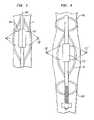
- FIGS. 3 , 4 , 5 and 6are views similar to FIG. 1 , but depicting apparatus according to further embodiments of the invention.
- FIG. 7is an end view of a transducer used in an embodiment of the invention.
- FIG. 8is a sectional view of the transducer of FIG. 7 .
- FIG. 9is a perspective view of a part of the transducer of FIGS. 7 and 8 .
- FIG. 10is a fragmentary view on an enlarged scale of the area indicated in FIG. 8 .
- Apparatus according to one embodiment of the inventionincludes a probe structure 710 incorporating a single multi-lumen catheter 716 .
- a first fitting 705 at the proximal end of the cathetercommunicates with lumen 701 whereas another fitting 707 at the proximal end of the catheter communicates with lumen 703 .
- An emitting element 720 having an emitting surface generally in the form of a surface of revolutionis mounted to catheter 716 adjacent the distal end 709 of the catheter.
- the emitting elementdefines a medial plane 721 perpendicular to central axis 724 midway between the proximal and distal ends of the emitting element.
- a bearing balloon 711surrounds the emitting element.
- the bearing balloonis formed from a flexible material such as a polymer.
- a flexible materialsuch as a polymer.
- such balloonsare inflated to a relatively high preselected inflation pressure, referred to herein as the “design inflation pressure,” such as a few atmospheres to 10 or 12 atmospheres. Inflation pressures of this order render the balloon relatively rigid. Stated another way, the balloon will assume a predictable, preselected shape when inflated to the design inflation pressure, with minimal deviation from this shape despite variations in external pressure applied by the surrounding blood and soft tissue.
- the balloon walldesirably has the minimum thickness required to withstand the design inflation pressure without rupturing, as, for example, about 0.001 inches (1 mil) or less, preferably about 0.5 mils or less.
- the bearing balloonIn its inflated configuration, the bearing balloon has a substantially cylindrical wall section 713 coaxial with the central axis 724 of the emitting element.
- the bearing ballooncommunicates with lumen 703 through a port 705 .
- a lens balloon 717surrounds the emitting element 720 within bearing balloon 711 .
- the lens balloonalso has a preselected shape in a fully inflated condition.
- the preselected shape of the lens balloonis surface of revolution about central axis 724 , concentric with the cylindrical section of bearing balloon 713 and with the cylindrical emitting element 720 .
- the lens balloonis convex. That is, the generatrix forming the surface of revolution defined by the lens balloon has its greatest radius adjacent the medial plane 721 of the emitting element.
- the interior of lens balloon 717is connected to lumen 701 by a port 719 .
- the distal end of the catheteris advanced into the body of a living subject while the balloons are in a deflated condition. This advancement is continued until the emitting element and balloons are disposed within a tubular anatomical structure such as a blood vessel as, for example, a pulmonary vein in a subject suffering from atrial fibrillation.
- a tubular anatomical structuresuch as a blood vessel as, for example, a pulmonary vein in a subject suffering from atrial fibrillation.
- the pulmonary vein Vtypically is not precisely round.
- the veinmay have the cross-sectional shape indicated by dot-dash lines in FIG. 10 .
- Lens balloon 717is inflated by passing a fluid having acoustic velocity less than that of aqueous fluids but having acoustic impedance close to that of an aqueous fluid as, for example, a fluorocarbon, into the balloon through fitting 705 , lumen 701 and port 719 .
- Bearing balloon 711is inflated with an aqueous fluid such as water or saline.
- the cylindrical section 713 of bearing balloon 711has a circumference larger than the normal, undistended circumference of the vein V. Therefore, inflation of bearing balloon 711 distends the vein slightly and places the vein wall V in close, intimate contact with the bearing balloon around the entire cylindrical section 713 .
- the amount of distentionis not critical. The distention desirably is sufficient to assure contact between the bearing balloon's cylindrical surface 713 and the vein wall at all points, but desirably not so great as to damage the vein wall.
- the circumference of the bearing balloon in its inflated conditionis selected to be about 5% to about 10% greater than the normal, undistended circumference of the vein wall.
- the bearing balloonhas a preselected shape with its cylindrical surface disposed at a known, predetermined distance from the central axis 724 , the central axis and hence the emitting element 720 and lens balloon 717 are positioned at precise distances from the vein wall, and are concentric with the vein wall, when the bearing balloon is inflated.
- Emitting element 720is actuated, as by applying signals to a connector 731 at the proximal end of the probe structure so that such signals can be conducted to the emitting element through conductors (not shown) carried in or along the probe structure.
- the emitting elementemits substantially cylindrical ultrasonic waves which propagate substantially radially as indicated by arrows 733 in FIG. 9 .
- the ostiumis composed entirely of myocardial tissue
- the veinis composed entirely of vein tissue except for abnormal strands of myocardial tissue in the case of patients suffering from atrial fibrillation. These abnormal strands act as electrical initiators or triggers to produce ectopic beats, i.e., disorganized beats.
- the transition regionincludes both myocardial and vein tissue.
- the ablationis conducted in the ostium, in the transition region or in the vein, it is normally regarded as desirable to provide complete transmural ablation, i.e., to ablate tissue entirely through the wall so as to be certain that the abnormal strands are ablated or fully isolated from the myocardial tissue of the heart by a barrier of scar tissue.
- any tubular internal organcan be treated in a manner similar to that described above to ablate the tissue surrounding the interior of the organ.
- gastroesophageal reflux diseaseor “GERD”
- abnormal tissues within the esophagus or stomachmay be treated by positioning apparatus as discussed above within the stomach and/or within the esophagus and ablating the abnormal tissue.
- the techniques discussed abovecan be used to treat tissues surrounding other tubular anatomical structures as, for example, structures of the digestive system, respiratory system or urinary system.
- the apparatuscan be employed to treat benign prostatic hyperplasia (“BPH”).
- BPHbenign prostatic hyperplasia
- the prostate gland surrounding the urethra in a male subjectswells and tends to constrict the urethra.
- the apparatusmay be inserted into the urethra and ultrasonic energy may be directed into a ring-like focal region outside of the urethra, within the surrounding prostatic tissue so as to ablate the prostate and relieve the swelling.
- the radial distance from the central axis of the apparatus to the focal regionmay be selected so as to place the focal region either within the prostate itself or within the capsule surrounding the prostate.
- the bearing balloonmay be omitted.
- the lens ballooninstead bears directly on the vein wall V. Because the lens balloon has a predetermined shape and size, it precisely locates the central axis 724 ′ of the emitting element 720 ′ and distends the tissue in substantially the same way as discussed above with respect to the bearing balloon of FIGS. 1 and 2 .
- the lens balloonis filled with a fluid such as a fluorocarbon or other liquid having acoustic velocity lower than that of aqueous fluids but having acoustic impedance close to that of an aqueous fluid.
- the tissue of the vein wallhas acoustic properties similar to those of water and other aqueous fluids.
- the lens balloon 717 ′′, emitting element 720 ′′ and hence the central axis 724 ′′may be held at a location substantially concentric with the vein wall by centering structures such as additional balloons 750 and 751 , umbrella-like structures or other expansible structures disposed adjacent the lens balloon, so that the lens balloon does not bear on the vein wall.
- the refractionoccurs at the interface between the fluid within the lens balloon 717 ′′ and the surrounding blood within the vein.
- the vein wallmay remain in its non-circular state during application of ultrasonic energy and hence the depth of focal region 737 ′′ within the tissue may vary somewhat.
- the space between the lens balloon and the vein wallmay be filled with another fluid as, for example, saline solution.
- Apparatus according to a further embodiment of the inventionincludes an emitting element 820 , lens balloon 817 and an outer balloon 811 generally similar to the corresponding elements discussed above with reference to FIGS. 1 and 2 .
- the preselected shape of lens balloon in its inflated conditionincludes a surface of revolution 801 which is substantially concentric with the emitting element and central axis 824 , but which has a concave shape. That is, the generatrix of surface of revolution 801 has its smallest radius or distance from axis 824 at a location adjacent the medial plane 821 of emitting element 820 , and surface 801 curves radially outwardly in axial directions away from this medial plane.
- the outer balloon 811 in its inflated conditionhas a similar concave surface of revolution 813 .
- the assemblyis positioned within a tubular anatomical structure such as a vein.
- the outer balloon 811is filled with a fluid having acoustic velocity less than the acoustic velocity of aqueous fluids, whereas the lens balloon is filled with an aqueous fluid or another fluid having acoustic velocity greater than that of the fluid in the outer balloon.
- the emitting elementis actuated to emit substantially cylindrical ultrasonic waves which propagate generally radially outwardly as indicated by arrows 833 .
- the acoustic wavesare refracted axially inwardly towards an annular focus 837 on the medial plane 821 at the interface between the lens balloon and the bearing balloon due to the difference in acoustic velocities between the fluids contained in these balloons.
- the fluid in outer balloon 811has an acoustic velocity lower than the acoustic velocity of the surrounding blood or other fluid in the anatomical structure
- the acoustic wavesare refracted again at the interface between the outer balloon and the surrounding tissues. This refraction directs the waves substantially radially, so that the waves propagate generally parallel to one another and generally radially as indicated by arrows 839 in a generally disc-shaped pattern.
- the acoustic waveseffectively irradiate a deep, annular region.
- the depth of penetration of the acoustic wavesis limited only by attenuation of the waves as they are absorbed by the tissue.
- the acoustic wavesare not focused to a point or line, but nonetheless are effectively concentrated within a relatively narrow axial region. This arrangement can provide effective heating even if the central axis of the apparatus is not precisely coaxial with the vein.
- regions of the outer balloon remote from the medial plane 821contact the vein wall.
- the entire assemblymay be held adjacent the center of the vein by auxiliary positioning structures as discussed above with reference to FIG. 4 .
- the lens balloon 817 ′is convex, and filled with an aqueous fluid.
- the outer balloon 811 ′is also convex but is filled with a fluid having acoustic velocity higher than that of water.
- the apparatusacts to direct the applied energy into an annular region.
- the reflector structuremay direct the energy into a region of a different shape.
- Thermal treatments other than ablationcan be performed.
- hyperthermiacan be applied to potentiate the action of a drug or other agent in a particular region of the body.
- the focal depthcan be varied by varying the inflation pressures within the various balloons.
- more readily distensible materialssuch as elastomeric materials may be used to form the refractive regions of the balloons.
- the focal length of an inflatable lenscan be adjusted while maintaining the shape of the lens constant by varying the composition of the fluid in the lens or the fluid in a surrounding balloon.
- the liquidswhich are used to inflate the balloons in the embodiments discussed above, can also serve as temperature control media.
- the source of liquid used to inflate a balloonmay include a pump for circulating the liquid into the interior space of the balloon through one lumen and withdrawing the liquid through the other lumen while maintaining the liquid in the balloon under the desired pressure.
- the liquid sourcecan be arranged to provide the liquid at a desired temperature. In this way, the thermal boundary condition at the wall of the anatomical structure is well controlled.
- the controlled temperaturemay be below normal body temperature to keep the interface cool and minimize or prevent ablation of epithelial cells lining the anatomical structure. Conversely, a higher boundary temperature will promote ablation at or near the surface of the wall.
- the fluid in the bearing balloonmay be maintained just below the temperature which will cause tissue damage independently of the ultrasonic energy as, for example, up to about 41° C. Similar arrangements can be employed in the other embodiments.
- Liquid circulationalso serves to cool the ultrasonic element.
- the liquid in the lens ballooncan be circulated and temperature-controlled.
- FIGS. 7-10A preferred ultrasonic transducer or emitter usable in the present invention is depicted in FIGS. 7-10 .
- This transduceris further described in U.S. patent application Ser. No. 09/904,620, entitled “Ultrasonic Transducers,” filed Jul. 13, 2001, now U.S. Pat. No. 6,763,722, the disclosure of which is hereby incorporated by reference herein.
- the emitterincludes an active piezoelectric element 1702 in the form of a thin cylindrical tube having an exterior or front surface 1704 and an interior or rear surface 1706 .
- An electrode 1708forms the front surface 1704 of the piezoelectric element, and a similar electrode 1707 forms the rear surface.
- the thickness of the electrodeis greatly exaggerated in FIGS. 20 and 22 for clarity of illustration.
- the electrodepreferably is formed by a thin metallic coating, such as a plated or sputtered coating of metal on the order of a few thousand Angstroms thick overlying the actual piezoelectric material.
- An internal structure 1710includes an inner support tube 1712 and an outer support tube 1714 .
- Support tubes 1712 and 1714desirably are formed from a metallic, electrically conductive material.
- inner support tube 1712has an outwardly projecting shoulder 1720 at one end.
- a similar shoulder 1722is provided at the opposite end.
- Outer support tube 1714has a cylindrical internal bore. Shoulders or rings 1720 and 1722 fit closely within the cylindrical bore of the outer support tube.
- Gap 1726is filled with a gas, such as normal room air, at the time the tubes are sealed to one another. This gas remains permanently within gap 1726 .
- Outer support tube 1714has a pair of outwardly projecting shoulders 1730 and 1732 at the ends of the outer support tube.
- Each shoulderhas arcuate surfaces 1734 connected by flats 1736 , so that each shoulder is generally in the form of a square with rounded corners.
- the arcuate surfaces 1734are concentric with the main portion of the support tube 1714 .
- the flats 1736are tangent to the cylindrical surface of the main portion of the support tube. As best seen in FIG.
- the tubular piezoelectric electric element 1702is supported on the arcuate surfaces 1734 of shoulders 1732 and 1730 , so that the inner surface 1706 of the piezoelectric element is concentric with the outer surface of support tube 1714 , but is spaced apart from the support tube so as to define a space in the form of a tubular passageway 1740 between the outer support tube and the inner or rear surface 1706 of the piezoelectric element.
- Passageway 1740is open to the exterior of the transducer through small gaps 1742 defined between the inner surface 1706 of the piezoelectric element and the flats 1736 of the shoulders on the outer support tube.
- the space or passageway 1740is filled with a liquid.
- the front surface of the emitter(the front surface 1704 of the active piezoelectric element) is acoustically coupled to the medium which is to receive ultrasonic energy from the emitter.
- the emitter of FIGS. 7-10may be used as the ultrasonic emitter apparatus of depicted in FIG. 1 .
- the liquid within lens balloon 717will be present as the acoustic medium at the front surface of the emitter, and will fill passageway 1740 .
- the source of lens fluidcirculates this liquid so that the liquid moves through passageway 1740 .
- the air or other gas in gap 1726forms a highly-reflective interface 1713 with the metallic material of the outer support tube 1714 .
- the emitteris excited by an electrical potential applied between electrodes 1707 and 1708 .
- This potentialis applied at a predetermined ultrasonic drive frequency as, for example, about 1-15 MHz.
- the potentialmay be applied through electrical conductors (not shown) extending between the proximal end of the probe structure and the emitter, using a conventional ultrasonic-frequency driver (not shown).
- the conductorsmay be provided as one or more miniature coaxial cables, each including an inner conductor and an outer conductor or jacket.
- the jackets of the coaxial cablesmay be soldered or otherwise bonded to the outer support tube, and hence electrically connected to the inner-surface electrode of the piezoelectric element, whereas the inner conductors may be connected to the outer-surface electrode 1708 .
- the reflective interface at surface 1713 ( FIG. 10 ) and the outer surface 1704 of the emitter, and the stack of materials between these surfaces,constitute a resonant unit.
- the piezoelectric materialAs the piezoelectric material is excited, it repeatedly grows and shrinks in the forward-to-rearward direction of the stack, i.e., in the direction between surfaces 1704 and 1706 .
- the ultrasonic vibrationspropagate through the stack, and are reflected forwardly at the interfaces within the stack and by the interface at surface 1713 , at the inner or rear surface of the stack.
- the dimensions of the various layers in the interior of the stack, between surfaces 1713 and 1704 (including the liquid layer within space 1740 )are selected so that the unit is resonant at the drive frequency, and so that the acoustic vibrations are emitted from the resonant unit principally through the front surface 1704 into the medium coupled to the front surface. That is, more energy passes through the interface 1704 at the outer or front surface of the stack than through interface 1713 .
- the reflective interface 1713is effectively exposed to the ultrasonic vibrations in the stack and, thus, plays a substantial role in directing emissions to the front of the stack.
- the liquid within passageway 1740effectively cools the piezoelectric element and other elements of the stack.
- the transducer element 1702is cooled at both its front surface and its rear surface.
- a conventional air-backed transducertypically has a layer of air directly behind the rear surface of the piezoelectric element and, accordingly, has little or no heat transfer from the rear surface of the piezoelectric element.
- an emitter in accordance with this designcan convert electrical power to acoustic power radiated into the surrounding medium through the front surface with an efficiency equal to the efficiency of an air-backed emitter.
- the emitter according to this designprovides this efficiency in conjunction with better heat transfer and, hence, can operate at substantially higher power levels than the equivalent air-backed transducer of the same size.
- the materials and dimensions of the various layers in the resonant unitdesirably are optimized to assure maximum efficiency at the desired operating frequency.
- Conventional modeling techniquesmay be employed for such optimization.
- One such techniqueis the well-known KLM Model described in Krimholtz et al., “New Equivalent Circuits for Elementary Piezoelectric Transducers,” Electronics Letters, Vol. 6, No. 13, pp. 398-399, Jun. 25, 1970, the disclosure of which is hereby incorporated by reference herein.
- the various layerscan be modeled as one-dimensional elements, with the only dimension corresponding to the dimension in the forward-to-rearward direction of the stack, i.e., the radial dimension in the embodiment of FIGS. 19-22 . More precise optimization can be provided by finite element analysis and/or physical modeling and testing.
- the liquid in space or passageway 1740forms an integral part of the resonant unit.
- the inner support tubeprovides a passage through the emitter for catheters, guidewires or other elements of the apparatus.
- the inner support tube, and any elements disposed within it,are effectively isolated from the ultrasonic vibrations in the resonant unit by reflective interface 1713 , and therefore do not affect performance of the emitter.
- tubular piezoelectric elementmade from a ceramic lead zirconate-titanate composition, known in the art by the designation “PZT-8.”
- the tubular transducerhas an internal diameter of 83 mils (0.083 inches; 2.1 mm) and a wall thickness of 10.5 mils (0.27 mm), so that the outer diameter of the piezoelectric element is 103 mils (2.6 mm).
- the outer diameter of outer support tube 1714is 72 mils (1.8 mm); and the annular passageway 1740 has a radial thickness of 5.5 mils (0.14 mm).
- the outer support tubeis formed from half-hard brass and has a wall thickness of 5 mils (0.13 mm).
- the dimension between shoulders 1720 and 1722is 325 mils (8.25 mm), and the effective length of the transducer is 8 mm.
- This transducerprovides peak efficiency at a driving frequency of 9 MHz. When operated at 9 MHz, the transducer provides over fifty percent (50%) efficiency at electrical power levels between 20 and 100 watts. When cooled by water flowing at a rate of a few ml per minute, the transducer has been operated for periods of several minutes or more at power levels up to 100 watts to provide approximately 51 watts of radiated acoustic power.
- the apparatus discussed abovecan be varied.
- the apparatuscan be used to apply ultrasonic energy in structures other than internal organs of living subjects.
- the transducer used as an emitteralso serves as a receiver in an ultrasonic imaging application.
- the transducercan be actuated intermittently and then used to detect echoes from structures surrounding the apparatus.
- the apparatusmay be arranged to provide a radially-directed radiation pattern such as that discussed with reference to FIG. 5 .
- Such apparatuscan be used, for example, in an intravascular ultrasound procedure or in other medical applications, or in non-medical applications such as in inspection of pipes or tubes.
- the apparatuscan be moved along the length of a structure to scan the radiating ultrasound along the length of the structure.
- the ultrasonic emitter discussed abovecan be replaced by an optical emitter as, for example, a fiber optic having a distal end disposed within the lens balloon and a proximal end connected to an external light source.
- the fiber opticis provided with a lens or conical mirror at its distal end to direct light radially outwardly.
- the fluids in the balloonsare selected to provide different optical indices of refraction, rather than to provide different acoustic velocities.
- the apparatusalso may include structures for placing the balloons and facilitating orderly collapse of the balloons as described in the copending, commonly assigned U.S. patent application Ser. No. 09/905,227, entitled “Thermal Treatment Methods And Apparatus With Focused Energy Application,” filed Jul. 13, 2001, now U.S. Pat. No. 6,635,054, the disclosure of which is hereby incorporated by reference herein. Other features disclosed in such application also can be employed.
Landscapes
- Health & Medical Sciences (AREA)
- Engineering & Computer Science (AREA)
- Surgery (AREA)
- Life Sciences & Earth Sciences (AREA)
- Public Health (AREA)
- Animal Behavior & Ethology (AREA)
- General Health & Medical Sciences (AREA)
- Nuclear Medicine, Radiotherapy & Molecular Imaging (AREA)
- Veterinary Medicine (AREA)
- Biomedical Technology (AREA)
- Heart & Thoracic Surgery (AREA)
- Medical Informatics (AREA)
- Molecular Biology (AREA)
- Otolaryngology (AREA)
- Plasma & Fusion (AREA)
- Physics & Mathematics (AREA)
- Cardiology (AREA)
- Mechanical Engineering (AREA)
- Orthopedic Medicine & Surgery (AREA)
- Vascular Medicine (AREA)
- Thermotherapy And Cooling Therapy Devices (AREA)
- Surgical Instruments (AREA)
- Cleaning By Liquid Or Steam (AREA)
- Ultra Sonic Daignosis Equipment (AREA)
- Transducers For Ultrasonic Waves (AREA)
- Investigating Or Analyzing Materials By The Use Of Ultrasonic Waves (AREA)
Abstract
Description
Claims (12)
Priority Applications (1)
| Application Number | Priority Date | Filing Date | Title |
|---|---|---|---|
| US11/267,123US7540846B2 (en) | 2000-07-13 | 2005-11-04 | Energy application with inflatable annular lens |
Applications Claiming Priority (4)
| Application Number | Priority Date | Filing Date | Title |
|---|---|---|---|
| US21864100P | 2000-07-13 | 2000-07-13 | |
| US09/904,963US20020068885A1 (en) | 2000-07-13 | 2001-07-13 | Energy application with inflatable annular lens |
| PCT/US2001/022221WO2002005720A1 (en) | 2000-07-13 | 2001-07-13 | Energy application with inflatable annular lens |
| US11/267,123US7540846B2 (en) | 2000-07-13 | 2005-11-04 | Energy application with inflatable annular lens |
Related Parent Applications (1)
| Application Number | Title | Priority Date | Filing Date |
|---|---|---|---|
| US09/904,963ContinuationUS20020068885A1 (en) | 2000-07-13 | 2001-07-13 | Energy application with inflatable annular lens |
Publications (2)
| Publication Number | Publication Date |
|---|---|
| US20060058711A1 US20060058711A1 (en) | 2006-03-16 |
| US7540846B2true US7540846B2 (en) | 2009-06-02 |
Family
ID=52471708
Family Applications (2)
| Application Number | Title | Priority Date | Filing Date |
|---|---|---|---|
| US09/904,963AbandonedUS20020068885A1 (en) | 2000-07-13 | 2001-07-13 | Energy application with inflatable annular lens |
| US11/267,123Expired - LifetimeUS7540846B2 (en) | 2000-07-13 | 2005-11-04 | Energy application with inflatable annular lens |
Family Applications Before (1)
| Application Number | Title | Priority Date | Filing Date |
|---|---|---|---|
| US09/904,963AbandonedUS20020068885A1 (en) | 2000-07-13 | 2001-07-13 | Energy application with inflatable annular lens |
Country Status (7)
| Country | Link |
|---|---|
| US (2) | US20020068885A1 (en) |
| EP (5) | EP2430997A3 (en) |
| JP (1) | JP2004503324A (en) |
| CN (1) | CN1239127C (en) |
| AU (2) | AU7346801A (en) |
| CA (1) | CA2415671C (en) |
| WO (1) | WO2002005720A1 (en) |
Cited By (22)
| Publication number | Priority date | Publication date | Assignee | Title |
|---|---|---|---|---|
| WO2011053757A1 (en) | 2009-10-30 | 2011-05-05 | Sound Interventions, Inc. | Method and apparatus for treatment of hypertension through percutaneous ultrasound renal denervation |
| US20130204167A1 (en)* | 2010-10-18 | 2013-08-08 | CardioSonic Ltd. | Ultrasound transceiver and cooling thereof |
| US8845629B2 (en) | 2002-04-08 | 2014-09-30 | Medtronic Ardian Luxembourg S.A.R.L. | Ultrasound apparatuses for thermally-induced renal neuromodulation |
| US8974445B2 (en) | 2009-01-09 | 2015-03-10 | Recor Medical, Inc. | Methods and apparatus for treatment of cardiac valve insufficiency |
| US9028417B2 (en) | 2010-10-18 | 2015-05-12 | CardioSonic Ltd. | Ultrasound emission element |
| US9326786B2 (en) | 2010-10-18 | 2016-05-03 | CardioSonic Ltd. | Ultrasound transducer |
| US9486270B2 (en) | 2002-04-08 | 2016-11-08 | Medtronic Ardian Luxembourg S.A.R.L. | Methods and apparatus for bilateral renal neuromodulation |
| US9700372B2 (en) | 2002-07-01 | 2017-07-11 | Recor Medical, Inc. | Intraluminal methods of ablating nerve tissue |
| WO2017120330A1 (en)* | 2016-01-05 | 2017-07-13 | Cardiofocus, Inc. | Ablation system with automated sweeping ablation energy element |
| EP3366249A1 (en) | 2017-02-28 | 2018-08-29 | Biosense Webster (Israel) Ltd. | Lens in balloon catheter |
| US10230041B2 (en) | 2013-03-14 | 2019-03-12 | Recor Medical, Inc. | Methods of plating or coating ultrasound transducers |
| US10335280B2 (en) | 2000-01-19 | 2019-07-02 | Medtronic, Inc. | Method for ablating target tissue of a patient |
| US10350440B2 (en) | 2013-03-14 | 2019-07-16 | Recor Medical, Inc. | Ultrasound-based neuromodulation system |
| US10357304B2 (en) | 2012-04-18 | 2019-07-23 | CardioSonic Ltd. | Tissue treatment |
| US10589130B2 (en) | 2006-05-25 | 2020-03-17 | Medtronic, Inc. | Methods of using high intensity focused ultrasound to form an ablated tissue area containing a plurality of lesions |
| US10933259B2 (en) | 2013-05-23 | 2021-03-02 | CardioSonic Ltd. | Devices and methods for renal denervation and assessment thereof |
| US10967160B2 (en) | 2010-10-18 | 2021-04-06 | CardioSonic Ltd. | Tissue treatment |
| US11318331B2 (en) | 2017-03-20 | 2022-05-03 | Sonivie Ltd. | Pulmonary hypertension treatment |
| US11357447B2 (en) | 2012-05-31 | 2022-06-14 | Sonivie Ltd. | Method and/or apparatus for measuring renal denervation effectiveness |
| US11389236B2 (en) | 2018-01-15 | 2022-07-19 | Cardiofocus, Inc. | Ablation system with automated ablation energy element |
| WO2022175754A1 (en) | 2021-02-19 | 2022-08-25 | Otsuka Medical Devices Co., Ltd. | Selectively insulated ultrasound transducers |
| WO2023002327A1 (en) | 2021-07-19 | 2023-01-26 | Otsuka Medical Devices Co., Ltd. | Methods and systems for determining body lumen size |
Families Citing this family (111)
| Publication number | Priority date | Publication date | Assignee | Title |
|---|---|---|---|---|
| US6161543A (en) | 1993-02-22 | 2000-12-19 | Epicor, Inc. | Methods of epicardial ablation for creating a lesion around the pulmonary veins |
| US6840936B2 (en) | 1996-10-22 | 2005-01-11 | Epicor Medical, Inc. | Methods and devices for ablation |
| US6719755B2 (en) | 1996-10-22 | 2004-04-13 | Epicor Medical, Inc. | Methods and devices for ablation |
| US6311692B1 (en) | 1996-10-22 | 2001-11-06 | Epicor, Inc. | Apparatus and method for diagnosis and therapy of electrophysiological disease |
| US7052493B2 (en) | 1996-10-22 | 2006-05-30 | Epicor Medical, Inc. | Methods and devices for ablation |
| US6805128B1 (en) | 1996-10-22 | 2004-10-19 | Epicor Medical, Inc. | Apparatus and method for ablating tissue |
| US8709007B2 (en) | 1997-10-15 | 2014-04-29 | St. Jude Medical, Atrial Fibrillation Division, Inc. | Devices and methods for ablating cardiac tissue |
| US8308719B2 (en) | 1998-09-21 | 2012-11-13 | St. Jude Medical, Atrial Fibrillation Division, Inc. | Apparatus and method for ablating tissue |
| EP1207788A4 (en) | 1999-07-19 | 2009-12-09 | St Jude Medical Atrial Fibrill | Apparatus and method for ablating tissue |
| US8974446B2 (en) | 2001-10-11 | 2015-03-10 | St. Jude Medical, Inc. | Ultrasound ablation apparatus with discrete staggered ablation zones |
| US8347891B2 (en)* | 2002-04-08 | 2013-01-08 | Medtronic Ardian Luxembourg S.A.R.L. | Methods and apparatus for performing a non-continuous circumferential treatment of a body lumen |
| WO2004004572A1 (en)* | 2002-07-08 | 2004-01-15 | Prorhythm, Inc. | Cardiac ablation using microbubbles |
| US7837676B2 (en)* | 2003-02-20 | 2010-11-23 | Recor Medical, Inc. | Cardiac ablation devices |
| DE10309605B4 (en)* | 2003-03-05 | 2011-07-07 | Siemens AG, 80333 | Ultrasound device with cooled lens |
| US20040226556A1 (en) | 2003-05-13 | 2004-11-18 | Deem Mark E. | Apparatus for treating asthma using neurotoxin |
| US7066895B2 (en)* | 2003-06-30 | 2006-06-27 | Ethicon, Inc. | Ultrasonic radial focused transducer for pulmonary vein ablation |
| US7753906B2 (en)* | 2004-09-14 | 2010-07-13 | Richard Esposito | Catheter having anchoring and stabilizing devices |
| US20060135953A1 (en)* | 2004-12-22 | 2006-06-22 | Wlodzimierz Kania | Tissue ablation system including guidewire with sensing element |
| US20060155269A1 (en)* | 2005-01-12 | 2006-07-13 | Prorhythm, Inc. | Epicardial ablation using focused ultrasound |
| JP2006223341A (en)* | 2005-02-15 | 2006-08-31 | Univ Nihon | Tissue disruption device |
| US8932208B2 (en) | 2005-05-26 | 2015-01-13 | Maquet Cardiovascular Llc | Apparatus and methods for performing minimally-invasive surgical procedures |
| US20070142884A1 (en)* | 2005-12-16 | 2007-06-21 | Acoustx Corporation | Methods and apparatuses for treating an esophageal disorder such as gastroesophageal reflux disease |
| US20070142699A1 (en)* | 2005-12-16 | 2007-06-21 | Acoustx Corporation | Methods and implantable apparatuses for treating an esophageal disorder such as gastroesophageal reflux disease |
| US10499937B2 (en) | 2006-05-19 | 2019-12-10 | Recor Medical, Inc. | Ablation device with optimized input power profile and method of using the same |
| CN103222894B (en)* | 2006-06-28 | 2015-07-01 | 美敦力Af卢森堡公司 | Methods and systems for thermally-induced renal neuromodulation |
| WO2009089372A2 (en)* | 2008-01-08 | 2009-07-16 | Cornova, Inc. | Systems and methods for analysis and treatment of a body lumen |
| KR101411099B1 (en)* | 2006-10-25 | 2014-06-27 | 수퍼 소닉 이매진 | Method for generating mechanical waves by creating an interfacial acoustic radiation force |
| US10463886B2 (en)* | 2007-02-22 | 2019-11-05 | Ramot At Tel-Aviv University Ltd. | Treating weakened vessel wall such as vulnerable plaque or aneurysms |
| CN101686830B (en)* | 2007-07-11 | 2012-05-30 | 皇家飞利浦电子股份有限公司 | Ultrasound assembly with adjustable fluid lens |
| WO2009045265A1 (en) | 2007-10-05 | 2009-04-09 | Maquet Cardiovascular, Llc | Devices and methods for minimally-invasive surgical procedures |
| US9066742B2 (en) | 2007-11-09 | 2015-06-30 | The Spectranetics Corporation | Intra-vascular device with pressure detection capabilities using pressure sensitive material |
| US8483831B1 (en) | 2008-02-15 | 2013-07-09 | Holaira, Inc. | System and method for bronchial dilation |
| US8979828B2 (en) | 2008-07-21 | 2015-03-17 | The Spectranetics Corporation | Tapered liquid light guide |
| US9421065B2 (en) | 2008-04-02 | 2016-08-23 | The Spectranetics Corporation | Liquid light-guide catheter with optically diverging tip |
| JP2011519699A (en) | 2008-05-09 | 2011-07-14 | インノブアトイブエ プルモナルイ ソルウトイオンス,インコーポレイティッド | Systems, assemblies and methods for treatment of bronchial trees |
| US10363057B2 (en)* | 2008-07-18 | 2019-07-30 | Vytronus, Inc. | System and method for delivering energy to tissue |
| JP2012508593A (en)* | 2008-11-12 | 2012-04-12 | コーニンクレッカ フィリップス エレクトロニクス エヌ ヴィ | Acoustic switch and catheter with acoustic switch |
| US9108037B2 (en)* | 2009-03-09 | 2015-08-18 | St. Jude Medical, Atrial Fibrillation Division, Inc. | Apparatus and method for tissue ablation with near-field cooling |
| US11998266B2 (en) | 2009-10-12 | 2024-06-04 | Otsuka Medical Devices Co., Ltd | Intravascular energy delivery |
| WO2011056684A2 (en) | 2009-10-27 | 2011-05-12 | Innovative Pulmonary Solutions, Inc. | Delivery devices with coolable energy emitting assemblies |
| US20110112400A1 (en)* | 2009-11-06 | 2011-05-12 | Ardian, Inc. | High intensity focused ultrasound catheter apparatuses, systems, and methods for renal neuromodulation |
| WO2011060200A1 (en) | 2009-11-11 | 2011-05-19 | Innovative Pulmonary Solutions, Inc. | Systems, apparatuses, and methods for treating tissue and controlling stenosis |
| US8911439B2 (en) | 2009-11-11 | 2014-12-16 | Holaira, Inc. | Non-invasive and minimally invasive denervation methods and systems for performing the same |
| JP6013186B2 (en) | 2009-11-13 | 2016-10-25 | セント ジュード メディカル インコーポレイテッド | Staggered arrangement of shochu elements |
| US8617150B2 (en) | 2010-05-14 | 2013-12-31 | Liat Tsoref | Reflectance-facilitated ultrasound treatment |
| US8956346B2 (en) | 2010-05-14 | 2015-02-17 | Rainbow Medical, Ltd. | Reflectance-facilitated ultrasound treatment and monitoring |
| US9242122B2 (en) | 2010-05-14 | 2016-01-26 | Liat Tsoref | Reflectance-facilitated ultrasound treatment and monitoring |
| CN103764225B (en)* | 2011-03-04 | 2017-06-09 | 彩虹医疗公司 | By applying the instrument that energy is treated and monitored to tissue |
| EP2696929A1 (en) | 2011-04-11 | 2014-02-19 | The Spectranetics Corporation | Needle and guidewire holder |
| ES2864589T3 (en) | 2011-04-12 | 2021-10-14 | Thermedical Inc | Devices for conformal therapy in fluid-enhanced ablation |
| US8909316B2 (en) | 2011-05-18 | 2014-12-09 | St. Jude Medical, Cardiology Division, Inc. | Apparatus and method of assessing transvascular denervation |
| WO2013047261A1 (en)* | 2011-09-27 | 2013-04-04 | テルモ株式会社 | Abrasion device |
| US9427579B2 (en) | 2011-09-29 | 2016-08-30 | Pacesetter, Inc. | System and method for performing renal denervation verification |
| US9707414B2 (en) | 2012-02-14 | 2017-07-18 | Rainbow Medical Ltd. | Reflectance-facilitated ultrasound treatment and monitoring |
| US20130253387A1 (en)* | 2012-03-08 | 2013-09-26 | Sonitec, LLC | Vibratory energy systems and methods for occluded body cavities |
| US8934988B2 (en) | 2012-03-16 | 2015-01-13 | St. Jude Medical Ab | Ablation stent with meander structure |
| KR101400981B1 (en)* | 2012-03-27 | 2014-05-30 | 주식회사 루트로닉 | Radio-frequency surgical electrode, radio-frequency surgical devices and method for controlling thereof |
| US9113929B2 (en) | 2012-04-19 | 2015-08-25 | St. Jude Medical, Cardiology Division, Inc. | Non-electric field renal denervation electrode |
| WO2013157208A1 (en)* | 2012-04-20 | 2013-10-24 | テルモ株式会社 | Vascular insertion type treatment device |
| WO2013157207A1 (en)* | 2012-04-20 | 2013-10-24 | テルモ株式会社 | Vascular insertion type treatment device |
| US10022176B2 (en) | 2012-08-15 | 2018-07-17 | Thermedical, Inc. | Low profile fluid enhanced ablation therapy devices and methods |
| CN104902836B (en) | 2012-11-05 | 2017-08-08 | 毕达哥拉斯医疗有限公司 | controlled tissue ablation |
| US9770593B2 (en) | 2012-11-05 | 2017-09-26 | Pythagoras Medical Ltd. | Patient selection using a transluminally-applied electric current |
| US9398933B2 (en) | 2012-12-27 | 2016-07-26 | Holaira, Inc. | Methods for improving drug efficacy including a combination of drug administration and nerve modulation |
| US9179997B2 (en) | 2013-03-06 | 2015-11-10 | St. Jude Medical, Cardiology Division, Inc. | Thermochromic polyvinyl alcohol based hydrogel artery |
| US10716914B2 (en) | 2013-03-12 | 2020-07-21 | St. Jude Medical, Cardiology Division, Inc. | Catheter system |
| US10328238B2 (en) | 2013-03-12 | 2019-06-25 | St. Jude Medical, Cardiology Division, Inc. | Catheter system |
| US9775966B2 (en) | 2013-03-12 | 2017-10-03 | St. Jude Medical, Cardiology Division, Inc. | Catheter system |
| US9510902B2 (en) | 2013-03-13 | 2016-12-06 | St. Jude Medical, Cardiology Division, Inc. | Ablation catheters and systems including rotational monitoring means |
| US9131982B2 (en) | 2013-03-14 | 2015-09-15 | St. Jude Medical, Cardiology Division, Inc. | Mediguide-enabled renal denervation system for ensuring wall contact and mapping lesion locations |
| US8876813B2 (en) | 2013-03-14 | 2014-11-04 | St. Jude Medical, Inc. | Methods, systems, and apparatus for neural signal detection |
| US9610396B2 (en) | 2013-03-15 | 2017-04-04 | Thermedical, Inc. | Systems and methods for visualizing fluid enhanced ablation therapy |
| US9561070B2 (en) | 2013-03-15 | 2017-02-07 | St. Jude Medical, Cardiology Division, Inc. | Ablation system, methods, and controllers |
| US9033972B2 (en) | 2013-03-15 | 2015-05-19 | Thermedical, Inc. | Methods and devices for fluid enhanced microwave ablation therapy |
| EP3345564A1 (en) | 2013-03-15 | 2018-07-11 | St. Jude Medical, Cardiology Division, Inc. | Multi-electrode ablation system with a controller for determining a thermal gain of each electrode |
| US9186212B2 (en) | 2013-03-15 | 2015-11-17 | St. Jude Medical, Cardiology Division, Inc. | Feedback systems and methods utilizing two or more sites along denervation catheter |
| US9974477B2 (en) | 2013-03-15 | 2018-05-22 | St. Jude Medical, Cardiology Division, Inc. | Quantification of renal denervation via alterations in renal blood flow pre/post ablation |
| US9179973B2 (en) | 2013-03-15 | 2015-11-10 | St. Jude Medical, Cardiology Division, Inc. | Feedback systems and methods for renal denervation utilizing balloon catheter |
| WO2014176205A1 (en) | 2013-04-25 | 2014-10-30 | St. Jude Medical, Cardiology Division, Inc. | Electrode assembly for catheter system |
| US9872728B2 (en) | 2013-06-28 | 2018-01-23 | St. Jude Medical, Cardiology Division, Inc. | Apparatuses and methods for affixing electrodes to an intravascular balloon |
| US20150011991A1 (en) | 2013-07-03 | 2015-01-08 | St. Jude Medical, Cardiology Division, Inc. | Electrode Assembly For Catheter System |
| WO2015038886A1 (en)* | 2013-09-12 | 2015-03-19 | Holaira, Inc. | Systems, devices, and methods for treating a pulmonary disease with ultrasound energy |
| US10231747B2 (en) | 2013-09-20 | 2019-03-19 | Ethicon Llc | Transducer features for ultrasonic surgical instrument |
| USD914883S1 (en) | 2013-10-23 | 2021-03-30 | St. Jude Medical, Cardiology Division, Inc. | Ablation generator |
| USD774043S1 (en) | 2013-10-23 | 2016-12-13 | St. Jude Medical, Cardiology Division, Inc. | Display screen with graphical user interface for ablation generator |
| USD747491S1 (en) | 2013-10-23 | 2016-01-12 | St. Jude Medical, Cardiology Division, Inc. | Ablation generator |
| US10856936B2 (en) | 2013-10-23 | 2020-12-08 | St. Jude Medical, Cardiology Division, Inc. | Electrode assembly for catheter system including thermoplastic-based struts |
| US10034705B2 (en) | 2013-10-24 | 2018-07-31 | St. Jude Medical, Cardiology Division, Inc. | High strength electrode assembly for catheter system including novel electrode |
| US9913961B2 (en) | 2013-10-24 | 2018-03-13 | St. Jude Medical, Cardiology Division, Inc. | Flexible catheter shaft and method of manufacture |
| WO2015061034A1 (en) | 2013-10-24 | 2015-04-30 | St. Jude Medical, Cardiology Division, Inc. | Flexible catheter shaft and method of manufacture |
| US10420604B2 (en) | 2013-10-28 | 2019-09-24 | St. Jude Medical, Cardiology Division, Inc. | Electrode assembly for catheter system including interlinked struts |
| US9861433B2 (en) | 2013-11-05 | 2018-01-09 | St. Jude Medical, Cardiology Division, Inc. | Helical-shaped ablation catheter and methods of use |
| US9999463B2 (en) | 2014-04-14 | 2018-06-19 | NeuroMedic, Inc. | Monitoring nerve activity |
| US20170027460A1 (en) | 2015-07-29 | 2017-02-02 | NeuroMedic, Inc. | Intraluminal microneurography probe |
| US12350050B2 (en) | 2014-04-14 | 2025-07-08 | Recor Medical, Inc. | Intraluminal microneurography probes and related systems and methods |
| US10398501B2 (en) | 2014-04-24 | 2019-09-03 | St. Jude Medical, Cardiology Division, Inc. | Ablation systems including pulse rate detector and feedback mechanism and methods of use |
| US10478249B2 (en) | 2014-05-07 | 2019-11-19 | Pythagoras Medical Ltd. | Controlled tissue ablation techniques |
| US10925579B2 (en) | 2014-11-05 | 2021-02-23 | Otsuka Medical Devices Co., Ltd. | Systems and methods for real-time tracking of a target tissue using imaging before and during therapy delivery |
| US10383685B2 (en) | 2015-05-07 | 2019-08-20 | Pythagoras Medical Ltd. | Techniques for use with nerve tissue |
| US9974983B2 (en) | 2015-11-12 | 2018-05-22 | SonaCare Medical, LLC | Tissue stabilization for therapeutic ultrasound |
| FR3050117B1 (en)* | 2016-04-15 | 2021-01-15 | Carthera | ULTRASONIC THERMAL ABLATION PROBE |
| WO2017199240A2 (en) | 2016-05-18 | 2017-11-23 | Pythagoras Medical Ltd. | Helical catheter |
| WO2017223264A1 (en) | 2016-06-23 | 2017-12-28 | St. Jude Medical, Cardiology Division, Inc. | Catheter system and electrode assembly for intraprocedural evaluation of renal denervation |
| US9743984B1 (en) | 2016-08-11 | 2017-08-29 | Thermedical, Inc. | Devices and methods for delivering fluid to tissue during ablation therapy |
| US20190009110A1 (en)* | 2017-07-06 | 2019-01-10 | Slender Medical Ltd. | Ultrasound energy applicator |
| US10959784B2 (en) | 2017-10-24 | 2021-03-30 | Biosense Webster (Israel) Ltd. | Determining balloon catheter contact with anatomy using ultrasound |
| US11083871B2 (en) | 2018-05-03 | 2021-08-10 | Thermedical, Inc. | Selectively deployable catheter ablation devices |
| US11918277B2 (en) | 2018-07-16 | 2024-03-05 | Thermedical, Inc. | Inferred maximum temperature monitoring for irrigated ablation therapy |
| CN110170114A (en)* | 2019-06-26 | 2019-08-27 | 深圳市静康医疗科技有限公司 | Balloon ultrasonic wave prostate treatment head in a kind of rectum |
| CN114983521B (en)* | 2022-06-10 | 2025-08-29 | 飞依诺科技股份有限公司 | Shock wave lithotripsy catheter and shock wave lithotripsy catheter system having the same |
| CN117018483B (en)* | 2023-10-08 | 2023-12-22 | 北京小超科技有限公司 | Differential multi-focus ultrasonic cavitation device with enhanced temperature |
Citations (141)
| Publication number | Priority date | Publication date | Assignee | Title |
|---|---|---|---|---|
| US3168659A (en) | 1960-01-11 | 1965-02-02 | Gen Motors Corp | Variable focus transducer |
| US4084582A (en) | 1976-03-11 | 1978-04-18 | New York Institute Of Technology | Ultrasonic imaging system |
| US4185501A (en) | 1978-02-13 | 1980-01-29 | Second Foundation | Ultrasonic sector scanner |
| US4194510A (en) | 1978-06-15 | 1980-03-25 | Second Foundation, Inc. | Ultrasonic focusing system |
| US4387720A (en) | 1980-12-29 | 1983-06-14 | Hewlett-Packard Company | Transducer acoustic lens |
| US4391281A (en) | 1977-01-06 | 1983-07-05 | Sri International | Ultrasonic transducer system and method |
| US4433692A (en) | 1981-05-20 | 1984-02-28 | Olympus Optical Co., Ltd. | Ultrasonic diagnosis device |
| US4672961A (en) | 1986-05-19 | 1987-06-16 | Davies David H | Retrolasing catheter and method |
| US4680499A (en) | 1985-04-10 | 1987-07-14 | Hitachi, Ltd. | Piezoelectric ultrasonic transducer with acoustic matching plate |
| US4685334A (en) | 1986-01-27 | 1987-08-11 | The Babcock & Wilcox Company | Method for ultrasonic detection of hydrogen damage in boiler tubes |
| US4691714A (en) | 1984-10-15 | 1987-09-08 | Adamtek Corporation | Rheological testing apparatus and method |
| US4722347A (en) | 1985-01-15 | 1988-02-02 | Applied Biometrics, Inc. | Apparatus for measuring cardiac output |
| US4800316A (en) | 1985-04-01 | 1989-01-24 | Shanghai Lamp Factory | Backing material for the ultrasonic transducer |
| US4841977A (en) | 1987-05-26 | 1989-06-27 | Inter Therapy, Inc. | Ultra-thin acoustic transducer and balloon catheter using same in imaging array subassembly |
| US4869263A (en) | 1988-02-04 | 1989-09-26 | Cardiometrics, Inc. | Device and method for measuring volumetric blood flow in a vessel |
| WO1990000420A1 (en) | 1988-07-13 | 1990-01-25 | Adrian Charles Rowland | Light delivery system |
| US4914510A (en) | 1988-12-23 | 1990-04-03 | North American Philips Corporation | Method for improving the white field uniformity of a projection color TV using CRTs having interference filters, projection color TV and CRTs resulting from the method |
| US4945912A (en) | 1988-11-25 | 1990-08-07 | Sensor Electronics, Inc. | Catheter with radiofrequency heating applicator |
| US4972826A (en) | 1987-07-23 | 1990-11-27 | Siemens Aktiengesellschaft | Shock wave generator for an extracorporeal lithotripsy apparatus |
| US5104393A (en) | 1989-08-30 | 1992-04-14 | Angelase, Inc. | Catheter |
| US5105116A (en) | 1989-05-31 | 1992-04-14 | Seikosha Co., Ltd. | Piezoelectric transducer and sound-generating device |
| US5117831A (en) | 1990-03-28 | 1992-06-02 | Cardiovascular Imaging Systems, Inc. | Vascular catheter having tandem imaging and dilatation components |
| US5135001A (en) | 1990-12-05 | 1992-08-04 | C. R. Bard, Inc. | Ultrasound sheath for medical diagnostic instruments |
| US5140987A (en) | 1989-03-17 | 1992-08-25 | Wayne State University | Method for transvenous ablation of cardiac electrically conductive tissue by laser photocoagulation |
| US5160336A (en) | 1987-11-18 | 1992-11-03 | Ferton Holding | Device for acting by ultrasonic vibrations on an object |
| US5167233A (en) | 1991-01-07 | 1992-12-01 | Endosonics Corporation | Dilating and imaging apparatus |
| US5209299A (en) | 1992-02-04 | 1993-05-11 | Ayres Robert N | Multiple chamber chemical injection system |
| US5217454A (en) | 1991-08-01 | 1993-06-08 | Angiolaz, Incorporated | Laser delivery catheter |
| US5226421A (en) | 1992-03-06 | 1993-07-13 | Cardiometrics, Inc. | Doppler elongate flexible member having an inflatable balloon mounted thereon |
| US5226430A (en) | 1984-10-24 | 1993-07-13 | The Beth Israel Hospital | Method for angioplasty |
| US5240005A (en) | 1990-11-22 | 1993-08-31 | Dornier Medizintechnik Gmbh | Acoustic focussing device |
| US5242441A (en) | 1992-02-24 | 1993-09-07 | Boaz Avitall | Deflectable catheter with rotatable tip electrode |
| US5242438A (en) | 1991-04-22 | 1993-09-07 | Trimedyne, Inc. | Method and apparatus for treating a body site with laterally directed laser radiation |
| US5281218A (en) | 1992-06-05 | 1994-01-25 | Cardiac Pathways Corporation | Catheter having needle electrode for radiofrequency ablation |
| US5281213A (en) | 1992-04-16 | 1994-01-25 | Implemed, Inc. | Catheter for ice mapping and ablation |
| US5293868A (en) | 1992-06-30 | 1994-03-15 | American Cardiac Ablation Co., Inc. | Cardiac ablation catheter having resistive mapping electrodes |
| US5295484A (en) | 1992-05-19 | 1994-03-22 | Arizona Board Of Regents For And On Behalf Of The University Of Arizona | Apparatus and method for intra-cardiac ablation of arrhythmias |
| US5305731A (en) | 1991-10-31 | 1994-04-26 | Siemens Aktiengesellschaft | Apparatus for generating acoustic wave having a liquid lens with an adjustable focal length |
| US5305755A (en) | 1991-03-12 | 1994-04-26 | Fujitsu Limited | Ultrasonic probe, having transducer array capable of turning around its aperture axis and having a convex lens comprising a viscous resin |
| US5364388A (en) | 1988-04-01 | 1994-11-15 | Koziol Jeffrey E | Beam delivery system for corneal surgery |
| US5385148A (en) | 1993-07-30 | 1995-01-31 | The Regents Of The University Of California | Cardiac imaging and ablation catheter |
| US5415654A (en) | 1993-10-05 | 1995-05-16 | S.L.T. Japan Co., Ltd. | Laser balloon catheter apparatus |
| US5419335A (en) | 1992-09-04 | 1995-05-30 | Siemens Aktiengesellschaft | Acoustic lens |
| US5421338A (en) | 1988-03-21 | 1995-06-06 | Boston Scientific Corporation | Acoustic imaging catheter and the like |
| US5423807A (en) | 1992-04-16 | 1995-06-13 | Implemed, Inc. | Cryogenic mapping and ablation catheter |
| US5423319A (en) | 1994-06-15 | 1995-06-13 | Hewlett-Packard Company | Integrated impedance matching layer to acoustic boundary problems for clinical ultrasonic transducers |
| US5454782A (en) | 1994-08-11 | 1995-10-03 | Perkins; Rodney C. | Translumenal circumferential energy delivery device |
| US5468239A (en) | 1992-04-13 | 1995-11-21 | Sorenson Laboratories, Inc. | Apparatus and methods for using a circumferential light-emitting surgical laser probe |
| US5471988A (en) | 1993-12-24 | 1995-12-05 | Olympus Optical Co., Ltd. | Ultrasonic diagnosis and therapy system in which focusing point of therapeutic ultrasonic wave is locked at predetermined position within observation ultrasonic scanning range |
| US5477736A (en) | 1994-03-14 | 1995-12-26 | General Electric Company | Ultrasonic transducer with lens having electrorheological fluid therein for dynamically focusing and steering ultrasound energy |
| US5488955A (en) | 1992-07-22 | 1996-02-06 | Hewlett Packard Company | Magnetostriction transducer and an intraoperative probe for acoustic imaging |
| US5513639A (en) | 1994-04-12 | 1996-05-07 | Fujitsu Limited | Balloon type ultrasonic diagnostic probe |
| US5575787A (en) | 1993-09-20 | 1996-11-19 | Abela Laser Systems, Inc. | Cardiac ablation catheters and method |
| US5575766A (en) | 1993-11-03 | 1996-11-19 | Daig Corporation | Process for the nonsurgical mapping and treatment of atrial arrhythmia using catheters guided by shaped guiding introducers |
| US5582609A (en) | 1993-10-14 | 1996-12-10 | Ep Technologies, Inc. | Systems and methods for forming large lesions in body tissue using curvilinear electrode elements |
| US5596989A (en) | 1993-12-28 | 1997-01-28 | Olympus Optical Co., Ltd. | Ultrasonic probe |
| US5606974A (en) | 1995-05-02 | 1997-03-04 | Heart Rhythm Technologies, Inc. | Catheter having ultrasonic device |
| US5620479A (en) | 1992-11-13 | 1997-04-15 | The Regents Of The University Of California | Method and apparatus for thermal therapy of tumors |
| US5630837A (en) | 1993-07-01 | 1997-05-20 | Boston Scientific Corporation | Acoustic ablation |
| US5655539A (en) | 1996-02-26 | 1997-08-12 | Abbott Laboratories | Method for conducting an ultrasound procedure using an ultrasound transmissive pad |
| US5676692A (en) | 1996-03-28 | 1997-10-14 | Indianapolis Center For Advanced Research, Inc. | Focussed ultrasound tissue treatment method |
| US5693043A (en) | 1985-03-22 | 1997-12-02 | Massachusetts Institute Of Technology | Catheter for laser angiosurgery |
| US5704361A (en) | 1991-11-08 | 1998-01-06 | Mayo Foundation For Medical Education And Research | Volumetric image ultrasound transducer underfluid catheter system |
| US5707352A (en) | 1989-08-28 | 1998-01-13 | Alliance Pharmaceutical Corp. | Pulmonary delivery of therapeutic agent |
| US5720287A (en) | 1993-07-26 | 1998-02-24 | Technomed Medical Systems | Therapy and imaging probe and therapeutic treatment apparatus utilizing it |
| US5762066A (en) | 1992-02-21 | 1998-06-09 | Ths International, Inc. | Multifaceted ultrasound transducer probe system and methods for its use |
| US5767692A (en) | 1996-02-26 | 1998-06-16 | Circuit Line Spa | Device for converting the test point grid of a machine for electrically testing unassembled printed circuit boards |
| WO1998041178A1 (en) | 1997-03-17 | 1998-09-24 | Summit Technology, Inc. | Methods and systems for correction of hyperopia and/or astigmatism using ablative radiation |
| US5817018A (en) | 1994-12-22 | 1998-10-06 | Aloka Co., Ltd. | Method for measuring speed of sound in tissue and tissue assessment apparatus |
| WO1998049957A1 (en) | 1997-05-09 | 1998-11-12 | The Regents Of The University Of California | Cardiac tissue ablation device and method of use |
| US5840076A (en) | 1996-04-12 | 1998-11-24 | Ep Technologies, Inc. | Tissue heating and ablation systems and methods using electrode structures with distally oriented porous regions |
| US5840031A (en) | 1993-07-01 | 1998-11-24 | Boston Scientific Corporation | Catheters for imaging, sensing electrical potentials and ablating tissue |
| WO1998052465A1 (en) | 1997-05-23 | 1998-11-26 | Transurgical, Inc. | Mri-guided therapeutic unit and methods |
| US5848969A (en)* | 1996-10-28 | 1998-12-15 | Ep Technologies, Inc. | Systems and methods for visualizing interior tissue regions using expandable imaging structures |
| US5860974A (en) | 1993-07-01 | 1999-01-19 | Boston Scientific Corporation | Heart ablation catheter with expandable electrode and method of coupling energy to an electrode on a catheter shaft |
| WO1999002096A1 (en) | 1997-07-08 | 1999-01-21 | The Regents Of The University Of California | Circumferential ablation device assembly and method |
| US5916213A (en) | 1997-02-04 | 1999-06-29 | Medtronic, Inc. | Systems and methods for tissue mapping and ablation |
| US5916170A (en) | 1996-09-24 | 1999-06-29 | The Board Of Trustees Of The Leland Stanford Junior University | Method and apparatus for curvature detection in vessels from phase shifts of a plurality of input electrical signals |
| US5921982A (en) | 1993-07-30 | 1999-07-13 | Lesh; Michael D. | Systems and methods for ablating body tissue |
| US5931811A (en) | 1996-10-28 | 1999-08-03 | C.R. Bard, Inc. | Steerable catheter with fixed curve |
| US5938660A (en) | 1997-06-27 | 1999-08-17 | Daig Corporation | Process and device for the treatment of atrial arrhythmia |
| US5964751A (en) | 1996-08-26 | 1999-10-12 | Illumenex Corporation | Light delivery system with blood flushing capability |
| WO1999044519A3 (en) | 1998-03-02 | 1999-10-28 | Atrionix Inc | Tissue ablation system and method for forming long linear lesion |
| WO1999052423A9 (en) | 1998-04-16 | 1999-12-02 | Bard Inc C R | Pulmonary vein ablation catheter |
| US6002955A (en) | 1996-11-08 | 1999-12-14 | Medtronic, Inc. | Stabilized electrophysiology catheter and method for use |
| US6004269A (en) | 1993-07-01 | 1999-12-21 | Boston Scientific Corporation | Catheters for imaging, sensing electrical potentials, and ablating tissue |
| US6013053A (en) | 1996-05-17 | 2000-01-11 | Qlt Photo Therapeutics Inc. | Balloon catheter for photodynamic therapy |
| US6012457A (en) | 1997-07-08 | 2000-01-11 | The Regents Of The University Of California | Device and method for forming a circumferential conduction block in a pulmonary vein |
| US6022319A (en) | 1991-05-23 | 2000-02-08 | Scimed Life Systems, Inc. | Intravascular device such as introducer sheath or balloon catheter or the like and methods for use thereof |
| US6024740A (en) | 1997-07-08 | 2000-02-15 | The Regents Of The University Of California | Circumferential ablation device assembly |
| US6055859A (en) | 1996-10-01 | 2000-05-02 | Agency Of Industrial Science And Technology | Non-contact micromanipulation method and apparatus |
| US6071279A (en) | 1996-12-19 | 2000-06-06 | Ep Technologies, Inc. | Branched structures for supporting multiple electrode elements |
| WO2000042934A1 (en) | 1999-01-20 | 2000-07-27 | Daig Corporation | Device for the treatment of atrial arrhythmia |
| US6094988A (en) | 1995-02-16 | 2000-08-01 | Precision Acoustics Limited | Electrical coupling for piezoelectric ultrasound detector |
| US6106474A (en) | 1997-11-19 | 2000-08-22 | Scimed Life Systems, Inc. | Aerogel backed ultrasound transducer |
| WO2000051511A1 (en) | 1999-03-02 | 2000-09-08 | Atrionix, Inc. | Positioning system for a pulmonary ostium ablator |
| US6117101A (en) | 1997-07-08 | 2000-09-12 | The Regents Of The University Of California | Circumferential ablation device assembly |
| WO2000027292A9 (en) | 1998-11-06 | 2000-09-28 | Mv Medical Devices Inc | Method and device for left atrial appendage occlusion |
| WO2000016850A9 (en) | 1998-09-21 | 2000-10-26 | Epicardia Inc | Apparatus and method for diagnosis and therapy of electrophysiological disease |
| US6146379A (en) | 1993-10-15 | 2000-11-14 | Ep Technologies, Inc. | Systems and methods for creating curvilinear lesions in body tissue |
| WO2000067656A1 (en) | 1999-05-11 | 2000-11-16 | Atrionix, Inc. | Tissue ablation device assembly and method for electrically isolating a pulmonary vein ostium from an atrial wall |
| WO2000067648A1 (en) | 1999-05-11 | 2000-11-16 | Atrionix, Inc. | Apparatus and method incorporating an ultrasound transducer onto a delivery member |
| WO2000067830A1 (en) | 1999-05-11 | 2000-11-16 | Atrionix, Inc. | Catheter positioning system |
| US6152920A (en) | 1997-10-10 | 2000-11-28 | Ep Technologies, Inc. | Surgical method and apparatus for positioning a diagnostic or therapeutic element within the body |
| US6163716A (en) | 1992-09-25 | 2000-12-19 | Ep Technologies, Inc. | Cardiac mapping and ablation systems |
| US6161543A (en) | 1993-02-22 | 2000-12-19 | Epicor, Inc. | Methods of epicardial ablation for creating a lesion around the pulmonary veins |
| US6164283A (en) | 1997-07-08 | 2000-12-26 | The Regents Of The University Of California | Device and method for forming a circumferential conduction block in a pulmonary vein |
| US6190382B1 (en) | 1998-12-14 | 2001-02-20 | Medwaves, Inc. | Radio-frequency based catheter system for ablation of body tissues |
| US6193713B1 (en) | 1997-12-23 | 2001-02-27 | Sulzer Osypka Gmbh | Method for the operation of a high frequency ablation apparatus and apparatus for the high frequency tissue ablation |
| US6196059B1 (en) | 1997-08-11 | 2001-03-06 | Fraunhofer Gesellschaft Zur Forderung Der Angewandten Forschung E.V. | Piezoelectric resonator, process for the fabrication thereof including its use as a sensor element for the determination of the concentration of a substance contained in a liquid and/or for the determination of the physical properties of the liquid |
| US6197023B1 (en) | 1997-04-01 | 2001-03-06 | Axel Muntermann | Apparatus and process for catheter ablation |
| US6200269B1 (en) | 1998-05-28 | 2001-03-13 | Diasonics, Ultrasound, Inc. | Forward-scanning ultrasound catheter probe |
| US6200315B1 (en) | 1997-12-18 | 2001-03-13 | Medtronic, Inc. | Left atrium ablation catheter |
| US6203531B1 (en) | 1993-11-03 | 2001-03-20 | Daig Corporation | Guiding introducers for use in the treatment of accessory pathways around the mitral valve using a retrograde approach |
| US6203525B1 (en) | 1996-12-19 | 2001-03-20 | Ep Technologies, Inc. | Catheterdistal assembly with pull wires |
| US6206831B1 (en) | 1999-01-06 | 2001-03-27 | Scimed Life Systems, Inc. | Ultrasound-guided ablation catheter and methods of use |
| US6212426B1 (en) | 1995-07-28 | 2001-04-03 | Scimed Life Systems, Inc. | Systems and methods for conducting electrophysiological testing using high-voltage energy pulses to stun tissue |
| US6231561B1 (en) | 1999-09-20 | 2001-05-15 | Appriva Medical, Inc. | Method and apparatus for closing a body lumen |
| US6241754B1 (en) | 1993-10-15 | 2001-06-05 | Ep Technologies, Inc. | Composite structures and methods for ablating tissue to form complex lesion patterns in the treatment of cardiac conditions and the like |
| US6245064B1 (en) | 1997-07-08 | 2001-06-12 | Atrionix, Inc. | Circumferential ablation device assembly |
| WO2000067832A3 (en) | 1999-05-11 | 2001-07-05 | Atrionix Inc | Balloon anchor wire |
| US20010007070A1 (en) | 1999-04-05 | 2001-07-05 | Medtronic, Inc. | Ablation catheter assembly and method for isolating a pulmonary vein |
| US6280402B1 (en) | 1995-03-31 | 2001-08-28 | Kabushiki Kaisha Toshiba | Ultrasound therapeutic apparatus |
| US6283127B1 (en) | 1992-12-03 | 2001-09-04 | Wesley D. Sterman | Devices and methods for intracardiac procedures |
| US6282949B1 (en) | 1997-03-10 | 2001-09-04 | Amersham Pharmacia Biotech Ab | Apparatus for detection of inhomogeneities in a liquid flow |
| US6311692B1 (en) | 1996-10-22 | 2001-11-06 | Epicor, Inc. | Apparatus and method for diagnosis and therapy of electrophysiological disease |
| US6315778B1 (en) | 1999-09-10 | 2001-11-13 | C. R. Bard, Inc. | Apparatus for creating a continuous annular lesion |
| US6330473B1 (en) | 1996-12-19 | 2001-12-11 | Ep Technologies, Inc. | Structures for supporting porous electrode elements |
| US6332880B1 (en) | 1996-12-19 | 2001-12-25 | Ep Technologies, Inc. | Loop structures for supporting multiple electrode elements |
| WO2000056237A9 (en) | 1999-03-19 | 2002-04-18 | Atrionix Inc | Atrial annulus ablation device |
| US20020065512A1 (en) | 2000-07-13 | 2002-05-30 | Todd Fjield | Thermal treatment methods and apparatus with focused energy application |
| US6398792B1 (en) | 1999-06-21 | 2002-06-04 | O'connor Lawrence | Angioplasty catheter with transducer using balloon for focusing of ultrasonic energy and method for use |
| US6461314B1 (en) | 1999-02-02 | 2002-10-08 | Transurgical, Inc. | Intrabody hifu applicator |
| US6492762B1 (en) | 1999-03-22 | 2002-12-10 | Transurgical, Inc. | Ultrasonic transducer, transducer array, and fabrication method |
| US6513385B1 (en) | 2001-05-08 | 2003-02-04 | Halliburton Energy Services, Inc. | Acoustic sensor for pipeline deposition characterization and monitoring |
| US6517536B2 (en) | 2000-04-27 | 2003-02-11 | Atricure, Inc. | Transmural ablation device and method |
| US20030050637A1 (en) | 1997-07-08 | 2003-03-13 | Maguire Mark A. | Tissue ablation device assembly and method for electrically isolating a pulmonary vein ostium from an atrial wall |
| US6543274B1 (en) | 1998-11-04 | 2003-04-08 | Robert Bosch Gmbh | Sensor array and method for determining the density and viscosity of a liquid |
| US6642515B1 (en) | 1999-03-30 | 2003-11-04 | Japan Science And Technology Corporation | Method and apparatus for electrospray mass spectrometric analysis |
| WO2000051683A9 (en) | 1999-03-02 | 2005-07-14 | Atrionix Inc | Atrial ablator having balloon and sensor |
| EP1042990B1 (en) | 1999-04-05 | 2006-10-18 | Medtronic, Inc. | Ablation catheter for isolating a pulmonary vein |
Family Cites Families (10)
| Publication number | Priority date | Publication date | Assignee | Title |
|---|---|---|---|---|
| ATE66157T1 (en)* | 1986-04-29 | 1991-08-15 | Hoechst Roussel Pharma | LAYER STRUCTURE FOR ADMINISTRATION OF CHEMICALS WITH CONTROLLED RELEASE RATE. |
| JPS63186229A (en)* | 1987-01-28 | 1988-08-01 | Fuji Photo Film Co Ltd | Photosensitive material |
| US5344435A (en)* | 1988-07-28 | 1994-09-06 | Bsd Medical Corporation | Urethral inserted applicator prostate hyperthermia |
| US5391197A (en)* | 1992-11-13 | 1995-02-21 | Dornier Medical Systems, Inc. | Ultrasound thermotherapy probe |
| DE69432510T2 (en)* | 1993-12-24 | 2003-12-24 | Olympus Optical Co., Ltd. | Device for ultrasound diagnosis and treatment, wherein the focal point of the therapeutic ultrasound wave is locked in a predetermined position within the ultrasound observation area |
| US5895356A (en)* | 1995-11-15 | 1999-04-20 | American Medical Systems, Inc. | Apparatus and method for transurethral focussed ultrasound therapy |
| JP3117934B2 (en)* | 1997-05-06 | 2000-12-18 | 住友ゴム工業株式会社 | Golf club shaft |
| EP1206771A1 (en)* | 1999-08-16 | 2002-05-22 | Ekos Corporation | Ultrasound assembly for use with a catheter |
| BR0001171A (en)* | 2000-03-23 | 2001-06-12 | Press Hold Ind E Com Ltda | Improvements made to tools used in crimping machines |
| US6763722B2 (en)* | 2001-07-13 | 2004-07-20 | Transurgical, Inc. | Ultrasonic transducers |
- 2001
- 2001-07-13EPEP11189580.1Apatent/EP2430997A3/ennot_activeWithdrawn
- 2001-07-13USUS09/904,963patent/US20020068885A1/ennot_activeAbandoned
- 2001-07-13EPEP11189578.5Apatent/EP2430996A3/ennot_activeWithdrawn
- 2001-07-13EPEP01952746Apatent/EP1299038B1/ennot_activeExpired - Lifetime
- 2001-07-13JPJP2002511660Apatent/JP2004503324A/enactivePending
- 2001-07-13EPEP11189579.3Apatent/EP2455015B1/ennot_activeExpired - Lifetime
- 2001-07-13CACA2415671Apatent/CA2415671C/ennot_activeExpired - Lifetime
- 2001-07-13AUAU7346801Apatent/AU7346801A/enactivePending
- 2001-07-13AUAU2001273468Apatent/AU2001273468B2/ennot_activeCeased
- 2001-07-13WOPCT/US2001/022221patent/WO2002005720A1/enactiveIP Right Grant
- 2001-07-13EPEP11189581.9Apatent/EP2430998A3/ennot_activeWithdrawn
- 2001-07-13CNCN01812752.5Apatent/CN1239127C/ennot_activeExpired - Fee Related
- 2005
- 2005-11-04USUS11/267,123patent/US7540846B2/ennot_activeExpired - Lifetime
Patent Citations (158)
| Publication number | Priority date | Publication date | Assignee | Title |
|---|---|---|---|---|
| US3168659A (en) | 1960-01-11 | 1965-02-02 | Gen Motors Corp | Variable focus transducer |
| US4084582A (en) | 1976-03-11 | 1978-04-18 | New York Institute Of Technology | Ultrasonic imaging system |
| US4391281A (en) | 1977-01-06 | 1983-07-05 | Sri International | Ultrasonic transducer system and method |
| US4185501A (en) | 1978-02-13 | 1980-01-29 | Second Foundation | Ultrasonic sector scanner |
| US4194510A (en) | 1978-06-15 | 1980-03-25 | Second Foundation, Inc. | Ultrasonic focusing system |
| US4387720A (en) | 1980-12-29 | 1983-06-14 | Hewlett-Packard Company | Transducer acoustic lens |
| US4433692A (en) | 1981-05-20 | 1984-02-28 | Olympus Optical Co., Ltd. | Ultrasonic diagnosis device |
| US4691714A (en) | 1984-10-15 | 1987-09-08 | Adamtek Corporation | Rheological testing apparatus and method |
| US5226430A (en) | 1984-10-24 | 1993-07-13 | The Beth Israel Hospital | Method for angioplasty |
| US4722347A (en) | 1985-01-15 | 1988-02-02 | Applied Biometrics, Inc. | Apparatus for measuring cardiac output |
| US5693043A (en) | 1985-03-22 | 1997-12-02 | Massachusetts Institute Of Technology | Catheter for laser angiosurgery |
| US4800316A (en) | 1985-04-01 | 1989-01-24 | Shanghai Lamp Factory | Backing material for the ultrasonic transducer |
| US4680499A (en) | 1985-04-10 | 1987-07-14 | Hitachi, Ltd. | Piezoelectric ultrasonic transducer with acoustic matching plate |
| US4685334A (en) | 1986-01-27 | 1987-08-11 | The Babcock & Wilcox Company | Method for ultrasonic detection of hydrogen damage in boiler tubes |
| US4672961A (en) | 1986-05-19 | 1987-06-16 | Davies David H | Retrolasing catheter and method |
| US4841977A (en) | 1987-05-26 | 1989-06-27 | Inter Therapy, Inc. | Ultra-thin acoustic transducer and balloon catheter using same in imaging array subassembly |
| US4972826A (en) | 1987-07-23 | 1990-11-27 | Siemens Aktiengesellschaft | Shock wave generator for an extracorporeal lithotripsy apparatus |
| US5160336A (en) | 1987-11-18 | 1992-11-03 | Ferton Holding | Device for acting by ultrasonic vibrations on an object |
| US4869263A (en) | 1988-02-04 | 1989-09-26 | Cardiometrics, Inc. | Device and method for measuring volumetric blood flow in a vessel |
| US5421338A (en) | 1988-03-21 | 1995-06-06 | Boston Scientific Corporation | Acoustic imaging catheter and the like |
| US5364388A (en) | 1988-04-01 | 1994-11-15 | Koziol Jeffrey E | Beam delivery system for corneal surgery |
| WO1990000420A1 (en) | 1988-07-13 | 1990-01-25 | Adrian Charles Rowland | Light delivery system |
| US4945912A (en) | 1988-11-25 | 1990-08-07 | Sensor Electronics, Inc. | Catheter with radiofrequency heating applicator |
| US5246438A (en) | 1988-11-25 | 1993-09-21 | Sensor Electronics, Inc. | Method of radiofrequency ablation |
| US4914510A (en) | 1988-12-23 | 1990-04-03 | North American Philips Corporation | Method for improving the white field uniformity of a projection color TV using CRTs having interference filters, projection color TV and CRTs resulting from the method |
| US5140987A (en) | 1989-03-17 | 1992-08-25 | Wayne State University | Method for transvenous ablation of cardiac electrically conductive tissue by laser photocoagulation |
| US5105116A (en) | 1989-05-31 | 1992-04-14 | Seikosha Co., Ltd. | Piezoelectric transducer and sound-generating device |
| US6166092A (en)* | 1989-08-28 | 2000-12-26 | Alliance Pharmaceutical, Corp. | Fluorocarbon compositions for pulmonary therapy |
| US5707352A (en) | 1989-08-28 | 1998-01-13 | Alliance Pharmaceutical Corp. | Pulmonary delivery of therapeutic agent |
| US5104393A (en) | 1989-08-30 | 1992-04-14 | Angelase, Inc. | Catheter |
| US5117831A (en) | 1990-03-28 | 1992-06-02 | Cardiovascular Imaging Systems, Inc. | Vascular catheter having tandem imaging and dilatation components |
| US5240005A (en) | 1990-11-22 | 1993-08-31 | Dornier Medizintechnik Gmbh | Acoustic focussing device |
| US5135001A (en) | 1990-12-05 | 1992-08-04 | C. R. Bard, Inc. | Ultrasound sheath for medical diagnostic instruments |
| US5167233A (en) | 1991-01-07 | 1992-12-01 | Endosonics Corporation | Dilating and imaging apparatus |
| US5305755A (en) | 1991-03-12 | 1994-04-26 | Fujitsu Limited | Ultrasonic probe, having transducer array capable of turning around its aperture axis and having a convex lens comprising a viscous resin |
| US5242438A (en) | 1991-04-22 | 1993-09-07 | Trimedyne, Inc. | Method and apparatus for treating a body site with laterally directed laser radiation |
| US6022319A (en) | 1991-05-23 | 2000-02-08 | Scimed Life Systems, Inc. | Intravascular device such as introducer sheath or balloon catheter or the like and methods for use thereof |
| US5217454A (en) | 1991-08-01 | 1993-06-08 | Angiolaz, Incorporated | Laser delivery catheter |
| US5305731A (en) | 1991-10-31 | 1994-04-26 | Siemens Aktiengesellschaft | Apparatus for generating acoustic wave having a liquid lens with an adjustable focal length |
| US5704361A (en) | 1991-11-08 | 1998-01-06 | Mayo Foundation For Medical Education And Research | Volumetric image ultrasound transducer underfluid catheter system |
| US5209299A (en) | 1992-02-04 | 1993-05-11 | Ayres Robert N | Multiple chamber chemical injection system |
| US5762066A (en) | 1992-02-21 | 1998-06-09 | Ths International, Inc. | Multifaceted ultrasound transducer probe system and methods for its use |
| US5242441A (en) | 1992-02-24 | 1993-09-07 | Boaz Avitall | Deflectable catheter with rotatable tip electrode |
| US5226421A (en) | 1992-03-06 | 1993-07-13 | Cardiometrics, Inc. | Doppler elongate flexible member having an inflatable balloon mounted thereon |
| US5468239A (en) | 1992-04-13 | 1995-11-21 | Sorenson Laboratories, Inc. | Apparatus and methods for using a circumferential light-emitting surgical laser probe |
| US5423807A (en) | 1992-04-16 | 1995-06-13 | Implemed, Inc. | Cryogenic mapping and ablation catheter |
| US5281213A (en) | 1992-04-16 | 1994-01-25 | Implemed, Inc. | Catheter for ice mapping and ablation |
| US5295484A (en) | 1992-05-19 | 1994-03-22 | Arizona Board Of Regents For And On Behalf Of The University Of Arizona | Apparatus and method for intra-cardiac ablation of arrhythmias |
| US5281218A (en) | 1992-06-05 | 1994-01-25 | Cardiac Pathways Corporation | Catheter having needle electrode for radiofrequency ablation |
| US5293868A (en) | 1992-06-30 | 1994-03-15 | American Cardiac Ablation Co., Inc. | Cardiac ablation catheter having resistive mapping electrodes |
| US5488955A (en) | 1992-07-22 | 1996-02-06 | Hewlett Packard Company | Magnetostriction transducer and an intraoperative probe for acoustic imaging |
| US5419335A (en) | 1992-09-04 | 1995-05-30 | Siemens Aktiengesellschaft | Acoustic lens |
| US6163716A (en) | 1992-09-25 | 2000-12-19 | Ep Technologies, Inc. | Cardiac mapping and ablation systems |
| US5620479A (en) | 1992-11-13 | 1997-04-15 | The Regents Of The University Of California | Method and apparatus for thermal therapy of tumors |
| US6283127B1 (en) | 1992-12-03 | 2001-09-04 | Wesley D. Sterman | Devices and methods for intracardiac procedures |
| US6161543A (en) | 1993-02-22 | 2000-12-19 | Epicor, Inc. | Methods of epicardial ablation for creating a lesion around the pulmonary veins |
| US5630837A (en) | 1993-07-01 | 1997-05-20 | Boston Scientific Corporation | Acoustic ablation |
| US6004269A (en) | 1993-07-01 | 1999-12-21 | Boston Scientific Corporation | Catheters for imaging, sensing electrical potentials, and ablating tissue |
| US5840031A (en) | 1993-07-01 | 1998-11-24 | Boston Scientific Corporation | Catheters for imaging, sensing electrical potentials and ablating tissue |
| US5860974A (en) | 1993-07-01 | 1999-01-19 | Boston Scientific Corporation | Heart ablation catheter with expandable electrode and method of coupling energy to an electrode on a catheter shaft |
| US5720287A (en) | 1993-07-26 | 1998-02-24 | Technomed Medical Systems | Therapy and imaging probe and therapeutic treatment apparatus utilizing it |
| US5921982A (en) | 1993-07-30 | 1999-07-13 | Lesh; Michael D. | Systems and methods for ablating body tissue |
| US5385148A (en) | 1993-07-30 | 1995-01-31 | The Regents Of The University Of California | Cardiac imaging and ablation catheter |
| US5575787A (en) | 1993-09-20 | 1996-11-19 | Abela Laser Systems, Inc. | Cardiac ablation catheters and method |
| US5415654A (en) | 1993-10-05 | 1995-05-16 | S.L.T. Japan Co., Ltd. | Laser balloon catheter apparatus |
| US5582609A (en) | 1993-10-14 | 1996-12-10 | Ep Technologies, Inc. | Systems and methods for forming large lesions in body tissue using curvilinear electrode elements |
| US6146379A (en) | 1993-10-15 | 2000-11-14 | Ep Technologies, Inc. | Systems and methods for creating curvilinear lesions in body tissue |
| US6241754B1 (en) | 1993-10-15 | 2001-06-05 | Ep Technologies, Inc. | Composite structures and methods for ablating tissue to form complex lesion patterns in the treatment of cardiac conditions and the like |
| US5575766A (en) | 1993-11-03 | 1996-11-19 | Daig Corporation | Process for the nonsurgical mapping and treatment of atrial arrhythmia using catheters guided by shaped guiding introducers |
| US6203531B1 (en) | 1993-11-03 | 2001-03-20 | Daig Corporation | Guiding introducers for use in the treatment of accessory pathways around the mitral valve using a retrograde approach |
| US5471988A (en) | 1993-12-24 | 1995-12-05 | Olympus Optical Co., Ltd. | Ultrasonic diagnosis and therapy system in which focusing point of therapeutic ultrasonic wave is locked at predetermined position within observation ultrasonic scanning range |
| US5596989A (en) | 1993-12-28 | 1997-01-28 | Olympus Optical Co., Ltd. | Ultrasonic probe |
| US5477736A (en) | 1994-03-14 | 1995-12-26 | General Electric Company | Ultrasonic transducer with lens having electrorheological fluid therein for dynamically focusing and steering ultrasound energy |
| US5513639A (en) | 1994-04-12 | 1996-05-07 | Fujitsu Limited | Balloon type ultrasonic diagnostic probe |
| US5423319A (en) | 1994-06-15 | 1995-06-13 | Hewlett-Packard Company | Integrated impedance matching layer to acoustic boundary problems for clinical ultrasonic transducers |
| US5454782A (en) | 1994-08-11 | 1995-10-03 | Perkins; Rodney C. | Translumenal circumferential energy delivery device |
| US5817018A (en) | 1994-12-22 | 1998-10-06 | Aloka Co., Ltd. | Method for measuring speed of sound in tissue and tissue assessment apparatus |
| US6094988A (en) | 1995-02-16 | 2000-08-01 | Precision Acoustics Limited | Electrical coupling for piezoelectric ultrasound detector |
| US6280402B1 (en) | 1995-03-31 | 2001-08-28 | Kabushiki Kaisha Toshiba | Ultrasound therapeutic apparatus |
| US5606974A (en) | 1995-05-02 | 1997-03-04 | Heart Rhythm Technologies, Inc. | Catheter having ultrasonic device |
| US6212426B1 (en) | 1995-07-28 | 2001-04-03 | Scimed Life Systems, Inc. | Systems and methods for conducting electrophysiological testing using high-voltage energy pulses to stun tissue |
| US5767692A (en) | 1996-02-26 | 1998-06-16 | Circuit Line Spa | Device for converting the test point grid of a machine for electrically testing unassembled printed circuit boards |
| US5655539A (en) | 1996-02-26 | 1997-08-12 | Abbott Laboratories | Method for conducting an ultrasound procedure using an ultrasound transmissive pad |
| US5676692A (en) | 1996-03-28 | 1997-10-14 | Indianapolis Center For Advanced Research, Inc. | Focussed ultrasound tissue treatment method |
| US5840076A (en) | 1996-04-12 | 1998-11-24 | Ep Technologies, Inc. | Tissue heating and ablation systems and methods using electrode structures with distally oriented porous regions |
| US6013053A (en) | 1996-05-17 | 2000-01-11 | Qlt Photo Therapeutics Inc. | Balloon catheter for photodynamic therapy |
| US5964751A (en) | 1996-08-26 | 1999-10-12 | Illumenex Corporation | Light delivery system with blood flushing capability |
| US5916170A (en) | 1996-09-24 | 1999-06-29 | The Board Of Trustees Of The Leland Stanford Junior University | Method and apparatus for curvature detection in vessels from phase shifts of a plurality of input electrical signals |
| US6055859A (en) | 1996-10-01 | 2000-05-02 | Agency Of Industrial Science And Technology | Non-contact micromanipulation method and apparatus |
| US6314962B1 (en) | 1996-10-22 | 2001-11-13 | Epicor, Inc. | Method of ablating tissue around the pulmonary veins |
| US6237605B1 (en) | 1996-10-22 | 2001-05-29 | Epicor, Inc. | Methods of epicardial ablation |
| US6314963B1 (en) | 1996-10-22 | 2001-11-13 | Epicor, Inc. | Method of ablating tissue from an epicardial location |
| US6311692B1 (en) | 1996-10-22 | 2001-11-06 | Epicor, Inc. | Apparatus and method for diagnosis and therapy of electrophysiological disease |
| US5848969A (en)* | 1996-10-28 | 1998-12-15 | Ep Technologies, Inc. | Systems and methods for visualizing interior tissue regions using expandable imaging structures |
| US5931811A (en) | 1996-10-28 | 1999-08-03 | C.R. Bard, Inc. | Steerable catheter with fixed curve |
| US6002955A (en) | 1996-11-08 | 1999-12-14 | Medtronic, Inc. | Stabilized electrophysiology catheter and method for use |
| US6071279A (en) | 1996-12-19 | 2000-06-06 | Ep Technologies, Inc. | Branched structures for supporting multiple electrode elements |
| US6203525B1 (en) | 1996-12-19 | 2001-03-20 | Ep Technologies, Inc. | Catheterdistal assembly with pull wires |
| US6332880B1 (en) | 1996-12-19 | 2001-12-25 | Ep Technologies, Inc. | Loop structures for supporting multiple electrode elements |
| US6330473B1 (en) | 1996-12-19 | 2001-12-11 | Ep Technologies, Inc. | Structures for supporting porous electrode elements |
| US5916213A (en) | 1997-02-04 | 1999-06-29 | Medtronic, Inc. | Systems and methods for tissue mapping and ablation |
| US6068629A (en) | 1997-02-04 | 2000-05-30 | Medtronic, Inc. | System and methods for tissue mapping and ablation |
| US6282949B1 (en) | 1997-03-10 | 2001-09-04 | Amersham Pharmacia Biotech Ab | Apparatus for detection of inhomogeneities in a liquid flow |
| WO1998041178A1 (en) | 1997-03-17 | 1998-09-24 | Summit Technology, Inc. | Methods and systems for correction of hyperopia and/or astigmatism using ablative radiation |
| US6197023B1 (en) | 1997-04-01 | 2001-03-06 | Axel Muntermann | Apparatus and process for catheter ablation |
| US6254599B1 (en) | 1997-05-09 | 2001-07-03 | Atrionix, Inc. | Circumferential ablation device assembly |
| US5971983A (en) | 1997-05-09 | 1999-10-26 | The Regents Of The University Of California | Tissue ablation device and method of use |
| WO1998049957A1 (en) | 1997-05-09 | 1998-11-12 | The Regents Of The University Of California | Cardiac tissue ablation device and method of use |
| WO1998052465A1 (en) | 1997-05-23 | 1998-11-26 | Transurgical, Inc. | Mri-guided therapeutic unit and methods |
| US6235025B1 (en) | 1997-06-27 | 2001-05-22 | Daig Corporation | Process and device for the treatment of atrial arrhythmia |
| US5938660A (en) | 1997-06-27 | 1999-08-17 | Daig Corporation | Process and device for the treatment of atrial arrhythmia |
| US6251109B1 (en) | 1997-06-27 | 2001-06-26 | Daig Corporation | Process and device for the treatment of atrial arrhythmia |
| US20030050637A1 (en) | 1997-07-08 | 2003-03-13 | Maguire Mark A. | Tissue ablation device assembly and method for electrically isolating a pulmonary vein ostium from an atrial wall |
| US6024740A (en) | 1997-07-08 | 2000-02-15 | The Regents Of The University Of California | Circumferential ablation device assembly |
| US6305378B1 (en) | 1997-07-08 | 2001-10-23 | The Regents Of The University Of California | Device and method for forming a circumferential conduction block in a pulmonary vein |
| US6012457A (en) | 1997-07-08 | 2000-01-11 | The Regents Of The University Of California | Device and method for forming a circumferential conduction block in a pulmonary vein |
| US6117101A (en) | 1997-07-08 | 2000-09-12 | The Regents Of The University Of California | Circumferential ablation device assembly |
| US6652515B1 (en) | 1997-07-08 | 2003-11-25 | Atrionix, Inc. | Tissue ablation device assembly and method for electrically isolating a pulmonary vein ostium from an atrial wall |
| US6164283A (en) | 1997-07-08 | 2000-12-26 | The Regents Of The University Of California | Device and method for forming a circumferential conduction block in a pulmonary vein |
| WO1999002096A1 (en) | 1997-07-08 | 1999-01-21 | The Regents Of The University Of California | Circumferential ablation device assembly and method |
| US6383151B1 (en) | 1997-07-08 | 2002-05-07 | Chris J. Diederich | Circumferential ablation device assembly |
| US6500174B1 (en) | 1997-07-08 | 2002-12-31 | Atrionix, Inc. | Circumferential ablation device assembly and methods of use and manufacture providing an ablative circumferential band along an expandable member |
| US6245064B1 (en) | 1997-07-08 | 2001-06-12 | Atrionix, Inc. | Circumferential ablation device assembly |
| US6196059B1 (en) | 1997-08-11 | 2001-03-06 | Fraunhofer Gesellschaft Zur Forderung Der Angewandten Forschung E.V. | Piezoelectric resonator, process for the fabrication thereof including its use as a sensor element for the determination of the concentration of a substance contained in a liquid and/or for the determination of the physical properties of the liquid |
| US6152920A (en) | 1997-10-10 | 2000-11-28 | Ep Technologies, Inc. | Surgical method and apparatus for positioning a diagnostic or therapeutic element within the body |
| US6106474A (en) | 1997-11-19 | 2000-08-22 | Scimed Life Systems, Inc. | Aerogel backed ultrasound transducer |
| US6200315B1 (en) | 1997-12-18 | 2001-03-13 | Medtronic, Inc. | Left atrium ablation catheter |
| US6193713B1 (en) | 1997-12-23 | 2001-02-27 | Sulzer Osypka Gmbh | Method for the operation of a high frequency ablation apparatus and apparatus for the high frequency tissue ablation |
| WO1999044519A3 (en) | 1998-03-02 | 1999-10-28 | Atrionix Inc | Tissue ablation system and method for forming long linear lesion |
| US6064902A (en) | 1998-04-16 | 2000-05-16 | C.R. Bard, Inc. | Pulmonary vein ablation catheter |
| WO1999052423A9 (en) | 1998-04-16 | 1999-12-02 | Bard Inc C R | Pulmonary vein ablation catheter |
| US6200269B1 (en) | 1998-05-28 | 2001-03-13 | Diasonics, Ultrasound, Inc. | Forward-scanning ultrasound catheter probe |
| WO2000016850A9 (en) | 1998-09-21 | 2000-10-26 | Epicardia Inc | Apparatus and method for diagnosis and therapy of electrophysiological disease |
| US6543274B1 (en) | 1998-11-04 | 2003-04-08 | Robert Bosch Gmbh | Sensor array and method for determining the density and viscosity of a liquid |
| US6152144A (en) | 1998-11-06 | 2000-11-28 | Appriva Medical, Inc. | Method and device for left atrial appendage occlusion |
| WO2000027292A9 (en) | 1998-11-06 | 2000-09-28 | Mv Medical Devices Inc | Method and device for left atrial appendage occlusion |
| US6190382B1 (en) | 1998-12-14 | 2001-02-20 | Medwaves, Inc. | Radio-frequency based catheter system for ablation of body tissues |
| US6206831B1 (en) | 1999-01-06 | 2001-03-27 | Scimed Life Systems, Inc. | Ultrasound-guided ablation catheter and methods of use |
| WO2000042934A1 (en) | 1999-01-20 | 2000-07-27 | Daig Corporation | Device for the treatment of atrial arrhythmia |
| US6461314B1 (en) | 1999-02-02 | 2002-10-08 | Transurgical, Inc. | Intrabody hifu applicator |
| WO2000051683A9 (en) | 1999-03-02 | 2005-07-14 | Atrionix Inc | Atrial ablator having balloon and sensor |
| WO2000051511A1 (en) | 1999-03-02 | 2000-09-08 | Atrionix, Inc. | Positioning system for a pulmonary ostium ablator |
| WO2000056237A9 (en) | 1999-03-19 | 2002-04-18 | Atrionix Inc | Atrial annulus ablation device |
| US6492762B1 (en) | 1999-03-22 | 2002-12-10 | Transurgical, Inc. | Ultrasonic transducer, transducer array, and fabrication method |
| US6642515B1 (en) | 1999-03-30 | 2003-11-04 | Japan Science And Technology Corporation | Method and apparatus for electrospray mass spectrometric analysis |
| EP1042990B1 (en) | 1999-04-05 | 2006-10-18 | Medtronic, Inc. | Ablation catheter for isolating a pulmonary vein |
| US20010007070A1 (en) | 1999-04-05 | 2001-07-05 | Medtronic, Inc. | Ablation catheter assembly and method for isolating a pulmonary vein |
| WO2000067656A1 (en) | 1999-05-11 | 2000-11-16 | Atrionix, Inc. | Tissue ablation device assembly and method for electrically isolating a pulmonary vein ostium from an atrial wall |
| WO2000067648A1 (en) | 1999-05-11 | 2000-11-16 | Atrionix, Inc. | Apparatus and method incorporating an ultrasound transducer onto a delivery member |
| WO2000067832A3 (en) | 1999-05-11 | 2001-07-05 | Atrionix Inc | Balloon anchor wire |
| WO2000067830A1 (en) | 1999-05-11 | 2000-11-16 | Atrionix, Inc. | Catheter positioning system |
| US6398792B1 (en) | 1999-06-21 | 2002-06-04 | O'connor Lawrence | Angioplasty catheter with transducer using balloon for focusing of ultrasonic energy and method for use |
| US6315778B1 (en) | 1999-09-10 | 2001-11-13 | C. R. Bard, Inc. | Apparatus for creating a continuous annular lesion |
| US6231561B1 (en) | 1999-09-20 | 2001-05-15 | Appriva Medical, Inc. | Method and apparatus for closing a body lumen |
| US6290674B1 (en) | 1999-09-20 | 2001-09-18 | Appriva Medical, Inc. | Method and apparatus for closing intracardiac septal defects |
| US6517536B2 (en) | 2000-04-27 | 2003-02-11 | Atricure, Inc. | Transmural ablation device and method |
| US20020065512A1 (en) | 2000-07-13 | 2002-05-30 | Todd Fjield | Thermal treatment methods and apparatus with focused energy application |
| US6513385B1 (en) | 2001-05-08 | 2003-02-04 | Halliburton Energy Services, Inc. | Acoustic sensor for pipeline deposition characterization and monitoring |
Non-Patent Citations (23)
Cited By (45)
| Publication number | Priority date | Publication date | Assignee | Title |
|---|---|---|---|---|
| US10335280B2 (en) | 2000-01-19 | 2019-07-02 | Medtronic, Inc. | Method for ablating target tissue of a patient |
| US9486270B2 (en) | 2002-04-08 | 2016-11-08 | Medtronic Ardian Luxembourg S.A.R.L. | Methods and apparatus for bilateral renal neuromodulation |
| US8845629B2 (en) | 2002-04-08 | 2014-09-30 | Medtronic Ardian Luxembourg S.A.R.L. | Ultrasound apparatuses for thermally-induced renal neuromodulation |
| US10293190B2 (en) | 2002-04-08 | 2019-05-21 | Medtronic Ardian Luxembourg S.A.R.L. | Thermally-induced renal neuromodulation and associated systems and methods |
| US9186198B2 (en) | 2002-04-08 | 2015-11-17 | Medtronic Ardian Luxembourg S.A.R.L. | Ultrasound apparatuses for thermally-induced renal neuromodulation and associated systems and methods |
| US10368944B2 (en) | 2002-07-01 | 2019-08-06 | Recor Medical, Inc. | Intraluminal method and apparatus for ablating nerve tissue |
| US9707034B2 (en) | 2002-07-01 | 2017-07-18 | Recor Medical, Inc. | Intraluminal method and apparatus for ablating nerve tissue |
| US9700372B2 (en) | 2002-07-01 | 2017-07-11 | Recor Medical, Inc. | Intraluminal methods of ablating nerve tissue |
| US10589130B2 (en) | 2006-05-25 | 2020-03-17 | Medtronic, Inc. | Methods of using high intensity focused ultrasound to form an ablated tissue area containing a plurality of lesions |
| US8974445B2 (en) | 2009-01-09 | 2015-03-10 | Recor Medical, Inc. | Methods and apparatus for treatment of cardiac valve insufficiency |
| US11185662B2 (en) | 2009-10-30 | 2021-11-30 | Recor Medical, Inc. | Method and apparatus for treatment of hypertension through percutaneous ultrasound renal denervation |
| EP3132828A1 (en) | 2009-10-30 | 2017-02-22 | ReCor Medical, Inc. | Method and apparatus for treatment of hypertension through percutaneous ultrasound renal denervation |
| EP2995350A1 (en) | 2009-10-30 | 2016-03-16 | ReCor Medical, Inc. | Method and apparatus for treatment of hypertension through percutaneous ultrasound renal denervation |
| WO2011053757A1 (en) | 2009-10-30 | 2011-05-05 | Sound Interventions, Inc. | Method and apparatus for treatment of hypertension through percutaneous ultrasound renal denervation |
| US9943666B2 (en) | 2009-10-30 | 2018-04-17 | Recor Medical, Inc. | Method and apparatus for treatment of hypertension through percutaneous ultrasound renal denervation |
| US9981108B2 (en) | 2009-10-30 | 2018-05-29 | Recor Medical, Inc. | Method and apparatus for treatment of hypertension through percutaneous ultrasound renal denervation |
| US10039901B2 (en) | 2009-10-30 | 2018-08-07 | Recor Medical, Inc. | Method and apparatus for treatment of hypertension through percutaneous ultrasound renal denervation |
| US12274833B2 (en) | 2009-10-30 | 2025-04-15 | Recor Medical, Inc. | Method and apparatus for treatment of hypertension through percutaneous ultrasound renal denervation |
| US12364501B2 (en) | 2010-10-18 | 2025-07-22 | Sonivie Ltd. | Ultrasound transducer and uses thereof |
| US11730506B2 (en) | 2010-10-18 | 2023-08-22 | Sonivie Ltd. | Ultrasound transducer and uses thereof |
| US9566456B2 (en)* | 2010-10-18 | 2017-02-14 | CardioSonic Ltd. | Ultrasound transceiver and cooling thereof |
| US9326786B2 (en) | 2010-10-18 | 2016-05-03 | CardioSonic Ltd. | Ultrasound transducer |
| US9028417B2 (en) | 2010-10-18 | 2015-05-12 | CardioSonic Ltd. | Ultrasound emission element |
| US20130204167A1 (en)* | 2010-10-18 | 2013-08-08 | CardioSonic Ltd. | Ultrasound transceiver and cooling thereof |
| US10368893B2 (en) | 2010-10-18 | 2019-08-06 | CardioSonic Ltd. | Ultrasound transducer and uses thereof |
| US10967160B2 (en) | 2010-10-18 | 2021-04-06 | CardioSonic Ltd. | Tissue treatment |
| US10357304B2 (en) | 2012-04-18 | 2019-07-23 | CardioSonic Ltd. | Tissue treatment |
| US11357447B2 (en) | 2012-05-31 | 2022-06-14 | Sonivie Ltd. | Method and/or apparatus for measuring renal denervation effectiveness |
| US12201444B2 (en) | 2012-05-31 | 2025-01-21 | Sonivie Ltd. | Method and/or apparatus for measuring renal denervation effectiveness |
| US10456605B2 (en) | 2013-03-14 | 2019-10-29 | Recor Medical, Inc. | Ultrasound-based neuromodulation system |
| US10350440B2 (en) | 2013-03-14 | 2019-07-16 | Recor Medical, Inc. | Ultrasound-based neuromodulation system |
| US12102845B2 (en) | 2013-03-14 | 2024-10-01 | Recor Medical, Inc. | Ultrasound-based neuromodulation system |
| US10230041B2 (en) | 2013-03-14 | 2019-03-12 | Recor Medical, Inc. | Methods of plating or coating ultrasound transducers |
| US10933259B2 (en) | 2013-05-23 | 2021-03-02 | CardioSonic Ltd. | Devices and methods for renal denervation and assessment thereof |
| US11832878B2 (en) | 2016-01-05 | 2023-12-05 | Cardiofocus, Inc. | Ablation system with automated ablation energy element |
| US11344365B2 (en) | 2016-01-05 | 2022-05-31 | Cardiofocus, Inc. | Ablation system with automated sweeping ablation energy element |
| WO2017120330A1 (en)* | 2016-01-05 | 2017-07-13 | Cardiofocus, Inc. | Ablation system with automated sweeping ablation energy element |
| EP3603556A1 (en) | 2017-02-28 | 2020-02-05 | Biosense Webster (Israel) Ltd. | Lens in balloon catheter |
| EP3366249A1 (en) | 2017-02-28 | 2018-08-29 | Biosense Webster (Israel) Ltd. | Lens in balloon catheter |
| US11318331B2 (en) | 2017-03-20 | 2022-05-03 | Sonivie Ltd. | Pulmonary hypertension treatment |
| US12251582B2 (en) | 2017-03-20 | 2025-03-18 | Sonivie Ltd. | Pulmonary hypertension treatment |
| US11389236B2 (en) | 2018-01-15 | 2022-07-19 | Cardiofocus, Inc. | Ablation system with automated ablation energy element |
| WO2022175754A1 (en) | 2021-02-19 | 2022-08-25 | Otsuka Medical Devices Co., Ltd. | Selectively insulated ultrasound transducers |
| WO2023002332A1 (en) | 2021-07-19 | 2023-01-26 | Otsuka Medical Devices Co., Ltd. | Methods and systems for determining body lumen size |
| WO2023002327A1 (en) | 2021-07-19 | 2023-01-26 | Otsuka Medical Devices Co., Ltd. | Methods and systems for determining body lumen size |
Also Published As
| Publication number | Publication date |
|---|---|
| EP2430997A2 (en) | 2012-03-21 |
| EP2430997A3 (en) | 2014-05-07 |
| AU7346801A (en) | 2002-01-30 |
| EP1299038B1 (en) | 2013-01-09 |
| EP2430998A2 (en) | 2012-03-21 |
| EP2455015A3 (en) | 2014-01-22 |
| JP2004503324A (en) | 2004-02-05 |
| US20060058711A1 (en) | 2006-03-16 |
| CA2415671C (en) | 2011-02-01 |
| EP1299038A1 (en) | 2003-04-09 |
| WO2002005720A1 (en) | 2002-01-24 |
| EP2430998A3 (en) | 2014-01-22 |
| EP2430996A3 (en) | 2014-01-22 |
| EP2430996A2 (en) | 2012-03-21 |
| CN1239127C (en) | 2006-02-01 |
| EP2455015A2 (en) | 2012-05-23 |
| CA2415671A1 (en) | 2002-01-24 |
| US20020068885A1 (en) | 2002-06-06 |
| CN1441651A (en) | 2003-09-10 |
| AU2001273468B2 (en) | 2005-05-26 |
| EP2455015B1 (en) | 2017-09-13 |
| EP1299038A4 (en) | 2005-04-20 |
Similar Documents
| Publication | Publication Date | Title |
|---|---|---|
| US7540846B2 (en) | Energy application with inflatable annular lens | |
| AU2001273468A1 (en) | Energy application with inflatable annular lens | |
| US7083614B2 (en) | Thermal treatment methods and apparatus with focused energy application | |
| EP1596746B1 (en) | Ultrasonic ablation devices | |
| AU2001273471A1 (en) | Thermal treatment methods and apparatus with focused energy application | |
| US10499937B2 (en) | Ablation device with optimized input power profile and method of using the same |
Legal Events
| Date | Code | Title | Description |
|---|---|---|---|
| AS | Assignment | Owner name:BOSTON SCIENTIFIC SCIMED, INC., MINNESOTA Free format text:PROMISSORY NOTE;ASSIGNOR:PRORHYTHM, INC.;REEL/FRAME:021617/0144 Effective date:20080915 | |
| STCF | Information on status: patent grant | Free format text:PATENTED CASE | |
| AS | Assignment | Owner name:RECOR MEDICAL, INC., NEW YORK Free format text:ASSIGNMENT OF ASSIGNORS INTEREST;ASSIGNOR:PRORHYTHM, INC.;REEL/FRAME:023731/0616 Effective date:20091013 | |
| FEPP | Fee payment procedure | Free format text:PAYOR NUMBER ASSIGNED (ORIGINAL EVENT CODE: ASPN); ENTITY STATUS OF PATENT OWNER: LARGE ENTITY | |
| FPAY | Fee payment | Year of fee payment:4 | |
| AS | Assignment | Owner name:SILICON VALLEY BANK, CALIFORNIA Free format text:SECURITY AGREEMENT;ASSIGNOR:RECOR MEDICAL, INC.;REEL/FRAME:033597/0710 Effective date:20140819 | |
| AS | Assignment | Owner name:RECOR MEDICAL, INC., FORMERLY KNOWN AS PRORHYTHM, Free format text:TERMINATION AND RELEASE OF PROMISSORY NOTE;ASSIGNOR:BOSTON SCIENTIFIC SCIMED, INC.;REEL/FRAME:033587/0144 Effective date:20140819 | |
| AS | Assignment | Owner name:RECOR MEDICAL INC., CALIFORNIA Free format text:RELEASE;ASSIGNOR:SILICON VALLEY BANK;REEL/FRAME:035801/0244 Effective date:20140819 | |
| FEPP | Fee payment procedure | Free format text:PAT HOLDER CLAIMS SMALL ENTITY STATUS, ENTITY STATUS SET TO SMALL (ORIGINAL EVENT CODE: LTOS); ENTITY STATUS OF PATENT OWNER: LARGE ENTITY | |
| AS | Assignment | Owner name:OTSUKA HOLDINGS CO., LTD., JAPAN Free format text:SECURITY INTEREST;ASSIGNOR:RECOR MEDICAL, INC.;REEL/FRAME:038579/0950 Effective date:20160512 | |
| FPAY | Fee payment | Year of fee payment:8 | |
| AS | Assignment | Owner name:OTSUKA MEDICAL DEVICES CO., LTD., JAPAN Free format text:ASSIGNMENT AND ASSUMPTION AGREEMENT OF SECURITY INTEREST RECORDED AT REEL/FRAME NO. 038579/0950;ASSIGNOR:OTSUKA HOLDINGS CO., LTD.;REEL/FRAME:045012/0414 Effective date:20180101 | |
| AS | Assignment | Owner name:RECOR MEDICAL, INC., CALIFORNIA Free format text:RELEASE OF SECURITY AGREEMENT COVERING INTERESTS IN PATENTS;ASSIGNOR:OTSUKA MEDICAL DEVICES CO., LTD.;REEL/FRAME:047827/0431 Effective date:20181206 | |
| FEPP | Fee payment procedure | Free format text:ENTITY STATUS SET TO UNDISCOUNTED (ORIGINAL EVENT CODE: BIG.); ENTITY STATUS OF PATENT OWNER: LARGE ENTITY | |
| MAFP | Maintenance fee payment | Free format text:PAYMENT OF MAINTENANCE FEE, 12TH YEAR, LARGE ENTITY (ORIGINAL EVENT CODE: M1553); ENTITY STATUS OF PATENT OWNER: LARGE ENTITY Year of fee payment:12 |