US7540831B2 - Pullup exercise assembly with rotatable handles and pivotable bar - Google Patents
Pullup exercise assembly with rotatable handles and pivotable barDownload PDFInfo
- Publication number
- US7540831B2 US7540831B2US12/042,368US4236808AUS7540831B2US 7540831 B2US7540831 B2US 7540831B2US 4236808 AUS4236808 AUS 4236808AUS 7540831 B2US7540831 B2US 7540831B2
- Authority
- US
- United States
- Prior art keywords
- bar
- assembly
- handle
- hook
- swing arm
- Prior art date
- Legal status (The legal status is an assumption and is not a legal conclusion. Google has not performed a legal analysis and makes no representation as to the accuracy of the status listed.)
- Active
Links
- 230000000712assemblyEffects0.000claimsabstractdescription20
- 238000000429assemblyMethods0.000claimsabstractdescription20
- 230000000284resting effectEffects0.000claims1
- 210000003205muscleAnatomy0.000description9
- 229920001971elastomerPolymers0.000description6
- 235000001674Agaricus brunnescensNutrition0.000description3
- 229910052782aluminiumInorganic materials0.000description3
- XAGFODPZIPBFFR-UHFFFAOYSA-NaluminiumChemical compound[Al]XAGFODPZIPBFFR-UHFFFAOYSA-N0.000description3
- 229910052751metalInorganic materials0.000description3
- 239000002184metalSubstances0.000description3
- 229910000831SteelInorganic materials0.000description2
- 210000003489abdominal muscleAnatomy0.000description2
- 229910045601alloyInorganic materials0.000description2
- 239000000956alloySubstances0.000description2
- 239000007769metal materialSubstances0.000description2
- 239000010959steelSubstances0.000description2
- 239000002023woodSubstances0.000description2
- 229910000669Chrome steelInorganic materials0.000description1
- 230000003187abdominal effectEffects0.000description1
- 239000004676acrylonitrile butadiene styreneSubstances0.000description1
- 150000001875compoundsChemical class0.000description1
- 239000013536elastomeric materialSubstances0.000description1
- 229920001821foam rubberPolymers0.000description1
- 238000003780insertionMethods0.000description1
- 230000037431insertionEffects0.000description1
- 238000012986modificationMethods0.000description1
- 230000004048modificationEffects0.000description1
- 239000004033plasticSubstances0.000description1
- 229920003023plasticPolymers0.000description1
Images


Classifications
- A—HUMAN NECESSITIES
- A63—SPORTS; GAMES; AMUSEMENTS
- A63B—APPARATUS FOR PHYSICAL TRAINING, GYMNASTICS, SWIMMING, CLIMBING, OR FENCING; BALL GAMES; TRAINING EQUIPMENT
- A63B1/00—Horizontal bars
- A—HUMAN NECESSITIES
- A63—SPORTS; GAMES; AMUSEMENTS
- A63B—APPARATUS FOR PHYSICAL TRAINING, GYMNASTICS, SWIMMING, CLIMBING, OR FENCING; BALL GAMES; TRAINING EQUIPMENT
- A63B21/00—Exercising apparatus for developing or strengthening the muscles or joints of the body by working against a counterforce, with or without measuring devices
- A63B21/06—User-manipulated weights
- A63B21/068—User-manipulated weights using user's body weight
- A—HUMAN NECESSITIES
- A63—SPORTS; GAMES; AMUSEMENTS
- A63B—APPARATUS FOR PHYSICAL TRAINING, GYMNASTICS, SWIMMING, CLIMBING, OR FENCING; BALL GAMES; TRAINING EQUIPMENT
- A63B21/00—Exercising apparatus for developing or strengthening the muscles or joints of the body by working against a counterforce, with or without measuring devices
- A63B21/16—Supports for anchoring force-resisters
- A63B21/1618—Supports for anchoring force-resisters on a door or a door frame
- A63B21/1627—Supports for anchoring force-resisters on a door or a door frame for anchoring on or between the vertical posts of a door frame
- A—HUMAN NECESSITIES
- A63—SPORTS; GAMES; AMUSEMENTS
- A63B—APPARATUS FOR PHYSICAL TRAINING, GYMNASTICS, SWIMMING, CLIMBING, OR FENCING; BALL GAMES; TRAINING EQUIPMENT
- A63B21/00—Exercising apparatus for developing or strengthening the muscles or joints of the body by working against a counterforce, with or without measuring devices
- A63B21/40—Interfaces with the user related to strength training; Details thereof
- A63B21/4027—Specific exercise interfaces
- A63B21/4033—Handles, pedals, bars or platforms
- A63B21/4035—Handles, pedals, bars or platforms for operation by hand
- A—HUMAN NECESSITIES
- A63—SPORTS; GAMES; AMUSEMENTS
- A63B—APPARATUS FOR PHYSICAL TRAINING, GYMNASTICS, SWIMMING, CLIMBING, OR FENCING; BALL GAMES; TRAINING EQUIPMENT
- A63B23/00—Exercising apparatus specially adapted for particular parts of the body
- A63B23/035—Exercising apparatus specially adapted for particular parts of the body for limbs, i.e. upper or lower limbs, e.g. simultaneously
- A63B23/12—Exercising apparatus specially adapted for particular parts of the body for limbs, i.e. upper or lower limbs, e.g. simultaneously for upper limbs or related muscles, e.g. chest, upper back or shoulder muscles
- A63B23/1209—Involving a bending of elbow and shoulder joints simultaneously
- A—HUMAN NECESSITIES
- A63—SPORTS; GAMES; AMUSEMENTS
- A63B—APPARATUS FOR PHYSICAL TRAINING, GYMNASTICS, SWIMMING, CLIMBING, OR FENCING; BALL GAMES; TRAINING EQUIPMENT
- A63B23/00—Exercising apparatus specially adapted for particular parts of the body
- A63B2023/003—Exercising apparatus specially adapted for particular parts of the body by torsion of the body part around its longitudinal axis
- A—HUMAN NECESSITIES
- A63—SPORTS; GAMES; AMUSEMENTS
- A63B—APPARATUS FOR PHYSICAL TRAINING, GYMNASTICS, SWIMMING, CLIMBING, OR FENCING; BALL GAMES; TRAINING EQUIPMENT
- A63B21/00—Exercising apparatus for developing or strengthening the muscles or joints of the body by working against a counterforce, with or without measuring devices
- A63B21/40—Interfaces with the user related to strength training; Details thereof
- A63B21/4001—Arrangements for attaching the exercising apparatus to the user's body, e.g. belts, shoes or gloves specially adapted therefor
- A63B21/4017—Arrangements for attaching the exercising apparatus to the user's body, e.g. belts, shoes or gloves specially adapted therefor to the upper limbs
- A—HUMAN NECESSITIES
- A63—SPORTS; GAMES; AMUSEMENTS
- A63B—APPARATUS FOR PHYSICAL TRAINING, GYMNASTICS, SWIMMING, CLIMBING, OR FENCING; BALL GAMES; TRAINING EQUIPMENT
- A63B2208/00—Characteristics or parameters related to the user or player
- A63B2208/02—Characteristics or parameters related to the user or player posture
- A63B2208/0285—Hanging
- A63B2208/029—Hanging upright
- A—HUMAN NECESSITIES
- A63—SPORTS; GAMES; AMUSEMENTS
- A63B—APPARATUS FOR PHYSICAL TRAINING, GYMNASTICS, SWIMMING, CLIMBING, OR FENCING; BALL GAMES; TRAINING EQUIPMENT
- A63B23/00—Exercising apparatus specially adapted for particular parts of the body
- A63B23/035—Exercising apparatus specially adapted for particular parts of the body for limbs, i.e. upper or lower limbs, e.g. simultaneously
- A63B23/03516—For both arms together or both legs together; Aspects related to the co-ordination between right and left side limbs of a user
- A63B23/03533—With separate means driven by each limb, i.e. performing different movements
- A—HUMAN NECESSITIES
- A63—SPORTS; GAMES; AMUSEMENTS
- A63B—APPARATUS FOR PHYSICAL TRAINING, GYMNASTICS, SWIMMING, CLIMBING, OR FENCING; BALL GAMES; TRAINING EQUIPMENT
- A63B23/00—Exercising apparatus specially adapted for particular parts of the body
- A63B23/035—Exercising apparatus specially adapted for particular parts of the body for limbs, i.e. upper or lower limbs, e.g. simultaneously
- A63B23/12—Exercising apparatus specially adapted for particular parts of the body for limbs, i.e. upper or lower limbs, e.g. simultaneously for upper limbs or related muscles, e.g. chest, upper back or shoulder muscles
- A63B23/1209—Involving a bending of elbow and shoulder joints simultaneously
- A63B23/1218—Chinning, pull-up, i.e. concentric movement
- Y—GENERAL TAGGING OF NEW TECHNOLOGICAL DEVELOPMENTS; GENERAL TAGGING OF CROSS-SECTIONAL TECHNOLOGIES SPANNING OVER SEVERAL SECTIONS OF THE IPC; TECHNICAL SUBJECTS COVERED BY FORMER USPC CROSS-REFERENCE ART COLLECTIONS [XRACs] AND DIGESTS
- Y10—TECHNICAL SUBJECTS COVERED BY FORMER USPC
- Y10S—TECHNICAL SUBJECTS COVERED BY FORMER USPC CROSS-REFERENCE ART COLLECTIONS [XRACs] AND DIGESTS
- Y10S482/00—Exercise devices
- Y10S482/904—Removably attached to wheelchair, home furnishing, or home structure
Definitions
- Example embodiments of the present inventiongenerally relate to an exercise assembly with rotatable handle assemblies and a bar assembly that enhances a pullup and/or chin-up exercise, and which can be adapted for different exercises due to a pivoting feature of the bar assembly.
- Pullups and chin-upsare exercises consisting of chinning oneself, as on a horizontal bar attached at each end to a frame of a door or doorpost, or of chinning oneself on other outdoor or fitness equipment. Both are compound exercises designed to work the muscles of the upper body. Basically, the difference lies in the grip.
- One performing a chin-upuses a narrow grip with the palms facing inward, while a pullup is done with typically a wider grip on the bar and with the palms facing outward.
- An example embodimentis directed to an exercise assembly that includes a bar connected between rotatable swing arm assemblies which extend along vertical faces of a frame and are adapted to reposition the bar from a fixed horizontal plane between the vertical faces to another lower horizontal position.
- the exercise assemblyincludes at least one handle assembly removably grasping the central bar and having a handle adapted to rotate 360 degrees during exercise.
- the handle assemblyincludes a J-shaped hook for placement on the bar.
- the J-hookhas a curved portion which grasps the bar to secure the assembly to the bar.
- the handle assemblyincludes a rotation assembly which permits the handle to be rotated 360 degrees around a vertical axis of the J-hook that is perpendicular to the bar during exercise.
- the bar assemblyincludes a central hollow bar and a pair of swing arms assemblies secured to either side of the central bar.
- Each swing arm assemblyincludes an end stub having a first and second end and a side strut having a first and second end. The first end of each end stub is connected to the first end of its corresponding side strut, and the second end of each end stub extends into a corresponding open end of the central bar.
- the second end of each side strutis secured to a vertical side of the frame between which the bar assembly is mounted.
- the side strut second endincludes a slotted aperture receiving a pivot pin therein.
- the interconnected central bar between swing arm assembliesis configured to be selectively rotated from a horizontal plane between the frame to another position away from the frame via the pivot pins.
- the exercise assemblyincludes a horizontally oriented bar having open, hollow ends and secured between a pair of swing arm assemblies.
- Each swing arm assemblyincludes a pivot pin at a lower end thereof that permits the bar to rotate a desired angle from vertical.
- the exercise assemblyincludes a pair of handle assemblies removably connected to the bar, each having a rotatable handle thereof.
- FIG. 1is a perspective view of an exercise assembly in accordance with the example embodiments.
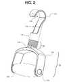
- FIG. 2is a perspective view of the handle assembly in accordance with the example embodiments.
- FIG. 3is an exploded view of the handle assembly of FIG. 2 to illustrate components in greater detail.
- FIG. 4is a front view of the handle assembly of FIG. 2 .
- FIG. 5is a cross-section view of the handle assembly in FIG. 4 taken across a line A-A.
- FIG. 6is a partial exploded view of the bar assembly 200 to illustrate components in greater detail.
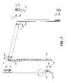
- FIG. 7is a partial exploded view of the bar assembly 200 to illustrate connection thereof between vertical surfaces.
- FIG. 8illustrates a user performing a standard chin-up or pullup on the exercise assembly 1000 .
- FIG. 9illustrates a user performing an Australian pullup on the exercise assembly 1000 .
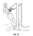
- FIG. 10illustrates a user performing a standing row on the exercise assembly 1000 .
- the example embodimentsin general relate to a pullup exercise assembly that includes rotatable handle assemblies and a pivotable bar assembly which can be oriented and secured into various positions between two vertical surfaces, such as the doorposts or sides of a door frame.
- the example exercise assemblycan combine the pullup and chin-up exercise, and can be used for performing core exercises such as an inverted pushup (known as an “Australian pullup”), standing row exercise and a dip exercise, for example.
- FIG. 1is a perspective view of an exercise assembly in accordance with the example embodiments.
- the pullup exercise assemblyhereafter “exercise assembly 1000 ”, is shown positioned between vertical surfaces 305 of a frame 300 .
- the exercise assembly 1000includes a bar assembly 200 comprising a central bar 205 connected between a pair of side arm assemblies 250 .
- the central bar 205may include a rubber overmold grip, for example.
- One or more handle assemblies 100can be affixed to the central bar 205 via a J-hook 110 that forms part of the handle assembly 100 .
- the handle assembly 100includes a J-hook 110 , a rotation assembly 120 , and a handle 130 .
- the J-hook 110grips the central bar 205 .
- the J-hook 110is connected to the rotation assembly 120 , which in turn is connection to the handle 130 .
- the J-hook 110remains fixed in place as the handle 130 can be rotated around the axis of the J-hook 110 via the rotation assembly 120 .
- Each side arm assembly 250includes a vertical side strut 252 connected to a horizontal end stub 254 .
- the end stub 254can be welded to the side strut 252 .
- the side struts 252extend along the vertical surface 305 between an upper hook mount 215 (which receives the portion of the side-arm assembly where the end stub 254 is attached to the side strut 254 ) and a lower mount 251 which includes a pivot pin 255 that extends through a slotted aperture 253 in the side strut 252 .
- the bar assembly 200can pivot about the pivot pins 255 .
- the bar assembly 200is first lifted out of the upper hook mounts 215 to unlock the pivot pin 255 , such that the pin 255 slides down into the wider part of the slotted aperture 253 .
- the bar assembly 200can then be rotated to a desired angle from vertical to perform a different exercise such as a dip, standing row, inverted pullup, etc.
- the bar assembly 200includes a central hollow metal bar 205 , which can be covered with an overmold grip, as previously described.
- the central bar 205is dimensioned so that its inner diameter is slightly larger than the outer diameter of the end stubs 254 . Accordingly, the end stubs 254 are received within the central bar 205 , and may be secured via retaining rings 210 .
- FIG. 2is a perspective view of the handle assembly in accordance with the example embodiments.
- the handle assembly 100is a standalone component; in other words it is freely removable from the bar 205 and is not fixed to the central bar 205 by a connection means which requires assembly/disassembly, such as a pin, screw or actuation mechanism which locks and unlocks the handle assembly 100 from the central bar 205 .
- the J-hook 110includes an upper curved portion 112 , an elongate intermediate body that is generally semi-circular in shape and which forms a circular shape at a base 116 of the hook 110 .
- the J-hook 110may be made of a metal material such as steel (which may be painted for stylistic purposes), and alloy thereof, aluminum, etc.
- the handle 130is connected to the rotation assembly 120 at a neck 139 .
- the handle 130includes a metal U-bracket 132 having a grip member 138 secured therein by way of threaded fasteners 134 .
- the U-bracket 132may be made of a medium or heavy gauge impact plastic such as acrylonitrile butadiene styrene (ABS), or of a metal material such steel, and alloy thereof, cast aluminum, etc.
- ABSacrylonitrile butadiene styrene
- the fasteners 134may be pins for example.
- FIG. 3is an exploded view of the handle assembly of FIG. 2 to illustrate components in greater detail.
- the rotation assembly 120includes a generally circular or cylindrical bearing 119 which is positioned between a washer 125 and an internally threaded plug 118 .
- the bearing 119permits the handle 130 to be rotated 360 degrees in either direction around a vertical axis of the J-hook 110 that is perpendicular to the bar 205 during exercise.
- the plug 118receives a hex bolt 126 such that the external threads on bolt 126 mate with internal threads within plug 118 to connect the J-hook 110 with handle 130 .
- the plug 118has a hex head shape that is a standard profile for an Allen wrench, and fits into a bore 117 formed in base 116 .
- bolt 126extends through neck 139 , washer 125 and bearing 119 , to be threaded into the plug 118 .
- the rotation assembly 120includes a rubber bellow 128 between the hook 110 and the neck 139 of the handle 130 .
- the rubber below 128attaches to the base 116 of the J-hook 110 .
- the rubber bellow 128mates with the neck 139 of handle 130 at its bottom so that a portion of the neck 139 contacts an interior surface of the bellow 128 .
- the rubber below 128encloses the washer 125 and a portion of the bolt 126 extending there through.
- the handle 130includes a hollow metal shaft 137 overlaid with or sheathed within grip member 138 .
- Shaft 137may be composed of chrome steel or aluminum, for example, and is secured to arms of the U-bracket 132 via insertion of fasteners 134 through holes 133 in the U-bracket 132 .
- the grip member 138may be made of a foam rubber or suitable elastomeric material and has a wider or thicker center portion which tapers down to the end portions of the grip member 148 .
- the bearing 119has an opening for receiving the bolt 126 .
- the bearing 119fits up into a bore 117 formed within the base 116 of the J-hook 110 , contacting an underside surface of plug 118 .
- FIG. 4is a front view of the handle assembly of FIG. 2
- FIG. 5is a cross-section view of the handle assembly in FIG. 4 taken across a line A-A.
- the bearing 119is designed to rotate around the fixed bolt 126 with the hook 110 being fixed on the central bar 205 and the user swiveling or rotating the handle 130 around the rubber bellow 128 such that the neck 139 and bearing 119 rotate together.
- the bearing 119 and handle 130rotate together for desired rotational movement in either direction.
- FIG. 6is a partial exploded view of the bar assembly 200 to illustrate components in greater detail
- FIG. 7is a partial exploded view of the bar assembly 200 to illustrate connection thereof between vertical surfaces.
- the outer ends of each end stub 254are attached to corresponding upper ends of the side struts 252 .
- the portion of the side-arm assembly 250 shown in circle B of FIG. 7is received into the upper hook mount 215 .
- the upper hook mount 215includes a channel 216 to receive the end of end stub 255 and top of side strut 252 at the intersection thereof.
- the channel 216has a sufficient width to accommodate the upper portion of the side-arm assembly 250 , as shown best in FIG. 7 .
- the upper hook mount 215is secured to a vertical surface 305 of a door frame 300 for example by suitable fasteners 217 (such as wood screws) through holes 219 formed in the upper hook mount 215 .
- a lower pivot mount 251is provided to enable the bar assembly 200 to be pivotable, once the top of the assembly 200 is lifted out of the channels 216 of the hook mounts 215 .
- the lower pivot mount 251is secured to the vertical surface 305 by suitable fasteners 258 (such as wood screws) through holes 259 formed in the lower pivot mount 251 .
- the lower pivot mount 251contains the pivot pin 255 .
- the pivot pin 255has a post with a mushroom head 257 that is configured to extend into the larger opening of the slotted aperture 253 .
- the mushroom head 257captures surfaces of the side struts 252 .
- the mushroom head 257 of the pivot pin 255captures surfaces of the side struts 252 along the slotted aperture 253 .
- Exercisingmay begin.
- the bar assembly 200can be removed from the channels 116 of the upper hook mounts 215 and rotated up to 180 degrees to a lower dimension, pivoting around the lower pivot mounts 251 so as to permit one to perform inverted pushup exercises from the ground up, a standing rowing exercise, a dip exercise etc.
- FIG. 8illustrates a user performing a conventional pullup or chin-up exercise on the exercise assembly 1000 . Since the handle assemblies 100 swivel, the user's hands can rotate as the user is moving up and down, engaging additional muscle groups.
- FIG. 9illustrates a user performing an Australian pullup on the exercise assembly 1000 .
- the fitness trainerhas oriented the exercise assembly 1000 such that the side struts 252 and central bar 205 have been rotated downward approximately 180 degrees from vertical. In this orientation, the trainer can perform a reverse pushup (Australian pullup) to work different muscles than can be achieved with a conventional pullup/chin-up bar.
- a reverse pushupAustralian pullup
- FIG. 10illustrates a user performing a standing row on the exercise assembly 1000 .
- the fitness trainerhas oriented the exercise assembly 1000 such that the side struts 252 and central bar 205 have been rotated downward approximately 120 degrees from vertical. In this orientation, the trainer can perform a rowing exercise to work the core abdominal muscles, in addition to working the biceps, deltoids, pectorals and other back muscles.
- FIGS. 8 through 10are merely example orientations of the exercise assembly 1000 to perform exercises other than standard pull-ups or chin-ups. It would be evident to one or skill in the art to re-position the side-arm assemblies 250 and central bar 205 to perform exercises other than shown in FIGS. 8-10 .
- the example exercise assembly 1000includes twisting handles 130 on adjustable swing arms 250 which attach to the central bar 205 to maximize muscle motion.
- the handle assemblies 100incorporate bearings 119 to enable 360 degree rotation. This permits the user's arms to move naturally, reduces strain on joints, and engages additional muscle groups as compared to the standard pullup bar.
- the example exercise assembly 1000thus may combine the standard pullup and chin-up exercises into one, and can facilitate additional workouts to core and abdominal muscle groups.
Landscapes
- Health & Medical Sciences (AREA)
- General Health & Medical Sciences (AREA)
- Physical Education & Sports Medicine (AREA)
- Orthopedic Medicine & Surgery (AREA)
- Life Sciences & Earth Sciences (AREA)
- Biophysics (AREA)
- Rehabilitation Tools (AREA)
Abstract
Description
Claims (12)
Priority Applications (15)
| Application Number | Priority Date | Filing Date | Title |
|---|---|---|---|
| US12/042,368US7540831B2 (en) | 2007-10-28 | 2008-03-05 | Pullup exercise assembly with rotatable handles and pivotable bar |
| CA002625400ACA2625400A1 (en) | 2007-10-26 | 2008-03-12 | Pullup exercise assembly with rotatable handles and pivotable bar |
| MX2008003707AMX2008003707A (en) | 2007-10-28 | 2008-03-14 | Pullup exercise assembly with rotatable handles and pivotable bar. |
| JP2008066667AJP4350151B2 (en) | 2007-10-28 | 2008-03-14 | Lifting assembly with rotatable handle and rotatable bar |
| TW097109336ATW200918116A (en) | 2007-10-28 | 2008-03-17 | Pullup exercise assembly with rotatable handles and pivotable bar |
| EP08250904AEP2052761A1 (en) | 2007-10-28 | 2008-03-17 | Pullup exercise assembly with rotatable handles and pivotable bar |
| KR1020080024540AKR20090042700A (en) | 2007-10-26 | 2008-03-17 | Jaw-dropper assembly with rotatable handles and rotatable bars |
| GB0804919AGB2454036A (en) | 2007-10-28 | 2008-03-17 | Pull-up exercise bar with rotatable handles |
| CNA2008100850848ACN101417168A (en) | 2007-10-26 | 2008-03-17 | Pullup exercise assembly with rotatable handles and pivotable bar |
| AU2008202177AAU2008202177A1 (en) | 2007-10-26 | 2008-05-16 | Pullup Exercise Assembly with Rotatable Handles and Pivotable Bar |
| NZ578530ANZ578530A (en) | 2007-10-28 | 2008-05-26 | Rotatable handle for pullup exercise assembly |
| NZ568567ANZ568567A (en) | 2007-10-28 | 2008-05-26 | Pullup exercise assembly with rotatable handles and pivotable bar |
| NZ578531ANZ578531A (en) | 2007-10-28 | 2008-05-26 | Pullup exercise assembly with rotatable handles and pivotable bar |
| BRPI0804678-6ABRPI0804678A2 (en) | 2007-10-28 | 2008-10-28 | lifting exercise set with swivel handles and swivel bar |
| JP2009109775AJP2009213896A (en) | 2007-10-28 | 2009-04-28 | Pullup exercise assembly with rotatable handles and pivotable bar |
Applications Claiming Priority (2)
| Application Number | Priority Date | Filing Date | Title |
|---|---|---|---|
| US98311107P | 2007-10-28 | 2007-10-28 | |
| US12/042,368US7540831B2 (en) | 2007-10-28 | 2008-03-05 | Pullup exercise assembly with rotatable handles and pivotable bar |
Related Child Applications (1)
| Application Number | Title | Priority Date | Filing Date |
|---|---|---|---|
| US12/425,760DivisionUS7566292B1 (en) | 2009-04-17 | 2009-04-17 | Handle assembly for use with an exercise bar |
Publications (2)
| Publication Number | Publication Date |
|---|---|
| US20090111661A1 US20090111661A1 (en) | 2009-04-30 |
| US7540831B2true US7540831B2 (en) | 2009-06-02 |
Family
ID=39328264
Family Applications (1)
| Application Number | Title | Priority Date | Filing Date |
|---|---|---|---|
| US12/042,368ActiveUS7540831B2 (en) | 2007-10-26 | 2008-03-05 | Pullup exercise assembly with rotatable handles and pivotable bar |
Country Status (12)
| Country | Link |
|---|---|
| US (1) | US7540831B2 (en) |
| EP (1) | EP2052761A1 (en) |
| JP (2) | JP4350151B2 (en) |
| KR (1) | KR20090042700A (en) |
| CN (1) | CN101417168A (en) |
| AU (1) | AU2008202177A1 (en) |
| BR (1) | BRPI0804678A2 (en) |
| CA (1) | CA2625400A1 (en) |
| GB (1) | GB2454036A (en) |
| MX (1) | MX2008003707A (en) |
| NZ (3) | NZ578531A (en) |
| TW (1) | TW200918116A (en) |
Cited By (15)
| Publication number | Priority date | Publication date | Assignee | Title |
|---|---|---|---|---|
| US20100234193A1 (en)* | 2009-03-11 | 2010-09-16 | Friedman Mark B | Exercise assembly |
| USD633961S1 (en) | 2010-02-28 | 2011-03-08 | Perfect Pushup Llc | Portable pull-up exercise device |
| US20110190103A1 (en)* | 2010-02-02 | 2011-08-04 | Fitova, Llc | Multi-function exercise system |
| US20120028770A1 (en)* | 2010-07-31 | 2012-02-02 | Leighton Barchi | Portable exercise device and method |
| US8177694B1 (en) | 2010-11-22 | 2012-05-15 | Walker Gavin M | Chin-up exercise apparatus and method |
| WO2013103603A1 (en)* | 2012-01-04 | 2013-07-11 | Brunswick Corporation | Chin-up assemblies |
| US20140323275A1 (en)* | 2013-04-24 | 2014-10-30 | II James Edward MOSES | Exercise system |
| US9079085B2 (en) | 2013-02-05 | 2015-07-14 | Stamina Products, Inc. | Pull-up bar with hand and finger holds |
| US20180126212A1 (en)* | 2016-11-07 | 2018-05-10 | Juan Ernesto Souffrain | Exercise accessory, system and method |
| US9999802B2 (en) | 2016-07-22 | 2018-06-19 | Donald Kilmon | Body weight exercise assembly configured to accept various discipline attachments |
| US20190060706A1 (en)* | 2017-08-22 | 2019-02-28 | Joseph P. Anastasi | Pull up accessory |
| US11123593B2 (en)* | 2017-02-10 | 2021-09-21 | Juan Ernesto Souffrain | Exercise accessories and system |
| US20210289763A1 (en)* | 2020-03-19 | 2021-09-23 | Joseph Alfaro | Fishing Rod Handling Device |
| US20230249023A1 (en)* | 2020-06-23 | 2023-08-10 | Eui Tak KIM | Muscle strength training apparatus |
| US20240068264A1 (en)* | 2022-08-23 | 2024-02-29 | Bram Owen Olson | Telescopic Equipment Hanging Device For Portable Shelters And Ground Blinds |
Families Citing this family (41)
| Publication number | Priority date | Publication date | Assignee | Title |
|---|---|---|---|---|
| IE86203B1 (en) | 2010-07-16 | 2013-06-19 | Michael Kehoe | An exercise device |
| CN103347570A (en) | 2010-10-08 | 2013-10-09 | 莎琳·N·沙 | Exercise device |
| CN103347571B (en)* | 2010-12-01 | 2015-11-25 | 随处健身有限责任公司 | Exercise bar attachment and method |
| US20120222269A1 (en)* | 2011-03-03 | 2012-09-06 | Anderson Steven L | Portable assist handle for vehicle entry and exit |
| US9017238B2 (en) | 2011-06-23 | 2015-04-28 | Hoist Fitness Systems, Inc. | Assisted chin/dip exercise apparatus with adjustable chin-up/pull-up handles |
| US8864638B2 (en) | 2011-09-15 | 2014-10-21 | Exemplar Design, Llc | Push-pull handles |
| US8714570B2 (en)* | 2011-10-14 | 2014-05-06 | Stable Innovations Ltd | Quick-disconnect handle for lifting and dumping of wheelbarrow cart |
| US9415253B2 (en) | 2012-10-29 | 2016-08-16 | Spx Fitness, Inc. | Exercise machine carriage handle system |
| KR200473089Y1 (en)* | 2012-10-31 | 2014-06-10 | 배승민 | Apparatus for clilbing |
| KR101280218B1 (en)* | 2013-01-30 | 2013-06-28 | 이재형 | Sport outfits for upper body muscular strength reinforcement |
| FR3009501B1 (en)* | 2013-08-09 | 2016-12-09 | David Forissier | AUTOBLOATING REMOVABLE HANDLE FOR MUSCULATION DEVICE AND CORRESPONDING TRACTION DEVICE |
| US9138606B2 (en) | 2013-10-25 | 2015-09-22 | Spx Fitness, Inc. | Exercise machine ergonomic handle system |
| TWI551330B (en)* | 2015-02-04 | 2016-10-01 | Pull up the movement | |
| US20160256720A1 (en)* | 2015-03-06 | 2016-09-08 | Turston Grant | Portable Exercise Apparatus |
| US11395936B1 (en) | 2015-12-16 | 2022-07-26 | Lagree Technologies, Inc. | Exercise machine carriage handle system |
| US9868011B2 (en) | 2016-01-22 | 2018-01-16 | Lagree Technologies, Inc. | Exercise machine resistance adjustment system |
| CN105944282A (en)* | 2016-06-14 | 2016-09-21 | 张高华 | Portable horizontal bar stretching automatic suspension device |
| US10857420B2 (en) | 2017-11-28 | 2020-12-08 | Lagree Technologies, Inc. | End platform for an exercise machine |
| US11001146B2 (en)* | 2019-04-05 | 2021-05-11 | Caterpillar Paving Products Inc. | Machine console system |
| US11446540B2 (en) | 2019-05-08 | 2022-09-20 | Lagree Technologies, Inc. | Exercise machine handle system |
| USD913387S1 (en)* | 2019-10-12 | 2021-03-16 | Linlin Li | Fitness equipment handle |
| CN111084963B (en)* | 2019-12-19 | 2021-04-09 | 江苏福维健康科技有限公司 | Pull-up exercising device for body building |
| US11654330B2 (en)* | 2020-02-21 | 2023-05-23 | Jayflex Fitness | Doorway pullup handle |
| CN111346344A (en)* | 2020-03-02 | 2020-06-30 | 连云港师范高等专科学校 | Comprehensive body-building training frame |
| US12226007B2 (en)* | 2020-05-06 | 2025-02-18 | Paul L. Williamson | Detachable shopping cart handle device |
| JP6841458B1 (en)* | 2020-06-10 | 2021-03-10 | トワロン株式会社 | Handheld hook |
| US11806569B2 (en)* | 2020-08-11 | 2023-11-07 | Jedi Markowski | Fitness system |
| US11701535B2 (en) | 2020-10-28 | 2023-07-18 | Arturo E. Holmes | Stretching apparatus |
| CN112619062A (en)* | 2020-12-23 | 2021-04-09 | 安徽晨风游乐设备集团有限公司 | Body-building apparatus of adjustable tensile training intensity |
| CN113144500B (en)* | 2021-05-07 | 2022-05-17 | 郑州大学体育学院 | A synthesize sports trainer for physical fitness test |
| KR102455185B1 (en) | 2021-06-21 | 2022-10-17 | 김의택 | Physical instrument for strengthening muscle |
| KR102448381B1 (en)* | 2022-04-26 | 2022-09-27 | 윤순용 | Versatile exercise handle with adjustable angle |
| CN114796972B (en)* | 2022-04-29 | 2023-05-12 | 重庆电子工程职业学院 | Portable physical training device |
| US20240189662A1 (en)* | 2022-12-07 | 2024-06-13 | My Flexx Fit, Llc | Supination exercise device and method of use |
| USD1038292S1 (en)* | 2023-01-10 | 2024-08-06 | Vincent Reese Long | Palm leverage handheld body strengthening apparatus handle |
| DE102023112030B3 (en)* | 2023-05-09 | 2024-08-29 | Christian Schlesener | Training device for climbers with a support that can be rotated around the axis of rotation as well as a system and mounting device |
| USD1088150S1 (en)* | 2023-08-09 | 2025-08-12 | Vive Health LLC | Ergonomic shoulder pulley handle |
| WO2025047054A1 (en)* | 2023-09-02 | 2025-03-06 | 有限会社ベルビー | Physical training apparatus and gripping tool for physical training apparatus |
| JP7385330B1 (en)* | 2023-09-02 | 2023-11-22 | 有限会社ベルビー | physical training equipment |
| JP7546335B1 (en) | 2024-05-27 | 2024-09-06 | 有限会社ベルビー | Physical training equipment and gripping devices for physical training equipment |
| CN221815223U (en)* | 2024-02-20 | 2024-10-11 | 永康市乔戈里电子商务有限责任公司 | A hook-shaped fitness handle with adjustable angle |
Citations (32)
| Publication number | Priority date | Publication date | Assignee | Title |
|---|---|---|---|---|
| US1386721A (en)* | 1919-09-10 | 1921-08-09 | Madden John | Spring-manipulating tool |
| US1824941A (en)* | 1929-11-20 | 1931-09-29 | Francis Joseph Winder | Hook |
| US2087757A (en)* | 1936-09-15 | 1937-07-20 | Donald J Foss | Drying rack |
| US2919134A (en)* | 1958-03-10 | 1959-12-29 | Walter Ratner | Mechanical exerciser |
| US2972419A (en)* | 1960-02-25 | 1961-02-21 | Zelen Eli | Clothes valet |
| US3424422A (en)* | 1967-01-16 | 1969-01-28 | George Klangos | Adjustable support |
| US3614097A (en)* | 1969-01-28 | 1971-10-19 | Blickman Inc | Weight lifting exercising apparatus |
| US3645212A (en) | 1970-03-04 | 1972-02-29 | Selim V Dahistrom | Straphangers device |
| US3716232A (en)* | 1970-06-05 | 1973-02-13 | Micron Res And Dev Corp | Exercise apparatus for attachment to an overhead frame |
| JPS5340191Y2 (en) | 1975-04-26 | 1978-09-28 | ||
| EP0116670A1 (en) | 1983-01-11 | 1984-08-29 | Heinz Leutheuser | Aid for chin-ups to relieve the forearm during weight-training back exercise, thereby permitting a more intensive training |
| US4529191A (en)* | 1983-03-07 | 1985-07-16 | Gravity Guidance, Inc. | Doorway mounted horizontal bar |
| US4750697A (en)* | 1985-09-16 | 1988-06-14 | Sergio Tontarelli | Hook for coat-hangers, equipped with a double-jointed supporting base |
| US4844448A (en)* | 1987-09-02 | 1989-07-04 | Niznik Michael D | Stand up exerciser |
| US4858977A (en)* | 1988-01-21 | 1989-08-22 | Mitchell Glen E | Self-attaching linking device |
| US4867444A (en)* | 1988-10-11 | 1989-09-19 | Castillo David D | Grip apparatus for weightlifting bar |
| US4893715A (en)* | 1989-01-09 | 1990-01-16 | Lillian Vernon Corporation | Closet extender |
| US4911572A (en)* | 1988-06-13 | 1990-03-27 | Houston Industries Incorporated | Cable tie back clamp |
| US5107996A (en)* | 1990-06-13 | 1992-04-28 | Greg Whittaker | Apparatus for the suspension storage of article of clothing |
| US5224607A (en)* | 1992-01-23 | 1993-07-06 | Koresko John J | Swivelling boot hanger |
| JPH08257164A (en) | 1995-03-23 | 1996-10-08 | Hideki Maruyama | Physical exercise assistant utensil |
| US5573484A (en)* | 1995-02-27 | 1996-11-12 | M. Michael Carpenter | Weighted auxiliary handle for dumbbell |
| US5588942A (en) | 1995-04-21 | 1996-12-31 | Dillard; Keith A. | Adjustable exercise device |
| JPH0912267A (en) | 1995-06-30 | 1997-01-14 | Kawaden Co Ltd | Stop position controlling method for traveling body |
| US5924667A (en)* | 1997-05-01 | 1999-07-20 | Grahn; Craig | Positioning device |
| US6328679B1 (en)* | 2000-06-19 | 2001-12-11 | Ellen Croft | Wall-mountable exercise device |
| US6416447B1 (en) | 1999-06-21 | 2002-07-09 | Larry Shane Harmon | Adaptable range-of-motion exercise apparatus |
| US20030186793A1 (en) | 2002-03-26 | 2003-10-02 | Philip Chen | Exercise apparatus |
| US20050085352A1 (en) | 2003-08-01 | 2005-04-21 | Baxter Brent A. | 360 degree rotator attachment for exercise equipment |
| US7066866B1 (en)* | 2003-07-10 | 2006-06-27 | Mobley Mitch T | Chin up bar assembly with sliding and swiveling handles |
| US7232105B2 (en)* | 2003-10-27 | 2007-06-19 | Atrium Medical Corporation | Method and apparatus for hanging a medical device |
| US7316324B1 (en)* | 2005-06-08 | 2008-01-08 | Myllykangas Martin W | Compact retractable towel bar |
Family Cites Families (7)
| Publication number | Priority date | Publication date | Assignee | Title |
|---|---|---|---|---|
| AU531843B2 (en)* | 1978-10-18 | 1983-09-08 | Willdon Displays Pty. Ltd. | Folding racks |
| US4696470A (en)* | 1986-01-13 | 1987-09-29 | Fenner Edwin H | Portable platform assembly for dancers and the like |
| US5104169A (en)* | 1991-08-08 | 1992-04-14 | Kopnski Thomas L | Handicap assist apparatus |
| US5540641A (en)* | 1994-10-31 | 1996-07-30 | Williams; Harold P. | Door frame mounted exerciser |
| JP3122020B2 (en)* | 1995-11-06 | 2001-01-09 | アップリカ▲葛▼西株式会社 | Horizontal bar equipment |
| US6247739B1 (en)* | 1998-03-06 | 2001-06-19 | Christopher Johns Lyon | Device for carrying containers |
| US6317924B1 (en)* | 1998-10-28 | 2001-11-20 | Mark Gallagher | Selectively rotatable handle for wheeled luggage |
- 2008
- 2008-03-05USUS12/042,368patent/US7540831B2/enactiveActive
- 2008-03-12CACA002625400Apatent/CA2625400A1/ennot_activeAbandoned
- 2008-03-14JPJP2008066667Apatent/JP4350151B2/ennot_activeExpired - Fee Related
- 2008-03-14MXMX2008003707Apatent/MX2008003707A/ennot_activeApplication Discontinuation
- 2008-03-17CNCNA2008100850848Apatent/CN101417168A/enactivePending
- 2008-03-17TWTW097109336Apatent/TW200918116A/enunknown
- 2008-03-17EPEP08250904Apatent/EP2052761A1/ennot_activeWithdrawn
- 2008-03-17KRKR1020080024540Apatent/KR20090042700A/ennot_activeCeased
- 2008-03-17GBGB0804919Apatent/GB2454036A/ennot_activeWithdrawn
- 2008-05-16AUAU2008202177Apatent/AU2008202177A1/ennot_activeAbandoned
- 2008-05-26NZNZ578531Apatent/NZ578531A/enunknown
- 2008-05-26NZNZ578530Apatent/NZ578530A/enunknown
- 2008-05-26NZNZ568567Apatent/NZ568567A/enunknown
- 2008-10-28BRBRPI0804678-6Apatent/BRPI0804678A2/ennot_activeIP Right Cessation
- 2009
- 2009-04-28JPJP2009109775Apatent/JP2009213896A/enactivePending
Patent Citations (32)
| Publication number | Priority date | Publication date | Assignee | Title |
|---|---|---|---|---|
| US1386721A (en)* | 1919-09-10 | 1921-08-09 | Madden John | Spring-manipulating tool |
| US1824941A (en)* | 1929-11-20 | 1931-09-29 | Francis Joseph Winder | Hook |
| US2087757A (en)* | 1936-09-15 | 1937-07-20 | Donald J Foss | Drying rack |
| US2919134A (en)* | 1958-03-10 | 1959-12-29 | Walter Ratner | Mechanical exerciser |
| US2972419A (en)* | 1960-02-25 | 1961-02-21 | Zelen Eli | Clothes valet |
| US3424422A (en)* | 1967-01-16 | 1969-01-28 | George Klangos | Adjustable support |
| US3614097A (en)* | 1969-01-28 | 1971-10-19 | Blickman Inc | Weight lifting exercising apparatus |
| US3645212A (en) | 1970-03-04 | 1972-02-29 | Selim V Dahistrom | Straphangers device |
| US3716232A (en)* | 1970-06-05 | 1973-02-13 | Micron Res And Dev Corp | Exercise apparatus for attachment to an overhead frame |
| JPS5340191Y2 (en) | 1975-04-26 | 1978-09-28 | ||
| EP0116670A1 (en) | 1983-01-11 | 1984-08-29 | Heinz Leutheuser | Aid for chin-ups to relieve the forearm during weight-training back exercise, thereby permitting a more intensive training |
| US4529191A (en)* | 1983-03-07 | 1985-07-16 | Gravity Guidance, Inc. | Doorway mounted horizontal bar |
| US4750697A (en)* | 1985-09-16 | 1988-06-14 | Sergio Tontarelli | Hook for coat-hangers, equipped with a double-jointed supporting base |
| US4844448A (en)* | 1987-09-02 | 1989-07-04 | Niznik Michael D | Stand up exerciser |
| US4858977A (en)* | 1988-01-21 | 1989-08-22 | Mitchell Glen E | Self-attaching linking device |
| US4911572A (en)* | 1988-06-13 | 1990-03-27 | Houston Industries Incorporated | Cable tie back clamp |
| US4867444A (en)* | 1988-10-11 | 1989-09-19 | Castillo David D | Grip apparatus for weightlifting bar |
| US4893715A (en)* | 1989-01-09 | 1990-01-16 | Lillian Vernon Corporation | Closet extender |
| US5107996A (en)* | 1990-06-13 | 1992-04-28 | Greg Whittaker | Apparatus for the suspension storage of article of clothing |
| US5224607A (en)* | 1992-01-23 | 1993-07-06 | Koresko John J | Swivelling boot hanger |
| US5573484A (en)* | 1995-02-27 | 1996-11-12 | M. Michael Carpenter | Weighted auxiliary handle for dumbbell |
| JPH08257164A (en) | 1995-03-23 | 1996-10-08 | Hideki Maruyama | Physical exercise assistant utensil |
| US5588942A (en) | 1995-04-21 | 1996-12-31 | Dillard; Keith A. | Adjustable exercise device |
| JPH0912267A (en) | 1995-06-30 | 1997-01-14 | Kawaden Co Ltd | Stop position controlling method for traveling body |
| US5924667A (en)* | 1997-05-01 | 1999-07-20 | Grahn; Craig | Positioning device |
| US6416447B1 (en) | 1999-06-21 | 2002-07-09 | Larry Shane Harmon | Adaptable range-of-motion exercise apparatus |
| US6328679B1 (en)* | 2000-06-19 | 2001-12-11 | Ellen Croft | Wall-mountable exercise device |
| US20030186793A1 (en) | 2002-03-26 | 2003-10-02 | Philip Chen | Exercise apparatus |
| US7066866B1 (en)* | 2003-07-10 | 2006-06-27 | Mobley Mitch T | Chin up bar assembly with sliding and swiveling handles |
| US20050085352A1 (en) | 2003-08-01 | 2005-04-21 | Baxter Brent A. | 360 degree rotator attachment for exercise equipment |
| US7232105B2 (en)* | 2003-10-27 | 2007-06-19 | Atrium Medical Corporation | Method and apparatus for hanging a medical device |
| US7316324B1 (en)* | 2005-06-08 | 2008-01-08 | Myllykangas Martin W | Compact retractable towel bar |
Cited By (20)
| Publication number | Priority date | Publication date | Assignee | Title |
|---|---|---|---|---|
| US20100234193A1 (en)* | 2009-03-11 | 2010-09-16 | Friedman Mark B | Exercise assembly |
| US20110190103A1 (en)* | 2010-02-02 | 2011-08-04 | Fitova, Llc | Multi-function exercise system |
| USD633961S1 (en) | 2010-02-28 | 2011-03-08 | Perfect Pushup Llc | Portable pull-up exercise device |
| US20120028770A1 (en)* | 2010-07-31 | 2012-02-02 | Leighton Barchi | Portable exercise device and method |
| US8177694B1 (en) | 2010-11-22 | 2012-05-15 | Walker Gavin M | Chin-up exercise apparatus and method |
| WO2013103603A1 (en)* | 2012-01-04 | 2013-07-11 | Brunswick Corporation | Chin-up assemblies |
| US8979717B2 (en) | 2012-01-04 | 2015-03-17 | Brunswick Corporation | Chin-up assemblies |
| US9079085B2 (en) | 2013-02-05 | 2015-07-14 | Stamina Products, Inc. | Pull-up bar with hand and finger holds |
| US20140323275A1 (en)* | 2013-04-24 | 2014-10-30 | II James Edward MOSES | Exercise system |
| US9999802B2 (en) | 2016-07-22 | 2018-06-19 | Donald Kilmon | Body weight exercise assembly configured to accept various discipline attachments |
| US20180126212A1 (en)* | 2016-11-07 | 2018-05-10 | Juan Ernesto Souffrain | Exercise accessory, system and method |
| US10695601B2 (en)* | 2016-11-07 | 2020-06-30 | Juan Ernesto Souffrain | Exercise accessory, system and method |
| US11123593B2 (en)* | 2017-02-10 | 2021-09-21 | Juan Ernesto Souffrain | Exercise accessories and system |
| US20190060706A1 (en)* | 2017-08-22 | 2019-02-28 | Joseph P. Anastasi | Pull up accessory |
| US10695609B2 (en)* | 2017-08-22 | 2020-06-30 | Joseph P. Anastasi | Pull up accessory |
| US11219796B2 (en)* | 2017-08-22 | 2022-01-11 | Joseph P. Anastasi | Pull up accessory |
| US20210289763A1 (en)* | 2020-03-19 | 2021-09-23 | Joseph Alfaro | Fishing Rod Handling Device |
| US11766035B2 (en)* | 2020-03-19 | 2023-09-26 | Joseph Alfaro | Fishing rod handling device |
| US20230249023A1 (en)* | 2020-06-23 | 2023-08-10 | Eui Tak KIM | Muscle strength training apparatus |
| US20240068264A1 (en)* | 2022-08-23 | 2024-02-29 | Bram Owen Olson | Telescopic Equipment Hanging Device For Portable Shelters And Ground Blinds |
Also Published As
| Publication number | Publication date |
|---|---|
| CA2625400A1 (en) | 2009-04-26 |
| KR20090042700A (en) | 2009-04-30 |
| MX2008003707A (en) | 2009-05-08 |
| JP2009106721A (en) | 2009-05-21 |
| NZ568567A (en) | 2009-09-25 |
| AU2008202177A1 (en) | 2009-05-14 |
| BRPI0804678A2 (en) | 2009-07-21 |
| TW200918116A (en) | 2009-05-01 |
| NZ578531A (en) | 2009-10-30 |
| CN101417168A (en) | 2009-04-29 |
| JP4350151B2 (en) | 2009-10-21 |
| NZ578530A (en) | 2009-10-30 |
| GB0804919D0 (en) | 2008-04-16 |
| US20090111661A1 (en) | 2009-04-30 |
| GB2454036A (en) | 2009-04-29 |
| EP2052761A1 (en) | 2009-04-29 |
| JP2009213896A (en) | 2009-09-24 |
Similar Documents
| Publication | Publication Date | Title |
|---|---|---|
| US7540831B2 (en) | Pullup exercise assembly with rotatable handles and pivotable bar | |
| US7566292B1 (en) | Handle assembly for use with an exercise bar | |
| US20100234193A1 (en) | Exercise assembly | |
| US6186930B1 (en) | Push-up trainer | |
| US4743018A (en) | Offset rotatable handle members for exercising apparatus | |
| US7935040B2 (en) | Method and apparatus for push up exercises | |
| US5588942A (en) | Adjustable exercise device | |
| US11752385B2 (en) | Exercise equipment clamp and handles | |
| US9302138B2 (en) | Upper extremity training apparatus | |
| US20100273615A1 (en) | Exercise apparatus | |
| US6338702B1 (en) | Exercise support bar | |
| US20170274245A1 (en) | Dip Fitness Device | |
| US7175572B2 (en) | Open hand gripped exercise device | |
| JP2819361B2 (en) | Arm type training device | |
| US11364414B2 (en) | Overhead bar mount exercise training device | |
| US10384091B1 (en) | Hand, wrist and forearm exerciser | |
| US11364415B2 (en) | Overhead bar mount exercise training device | |
| DE202008003744U1 (en) | Pull-up exercise device with rotating handles and swiveling rod | |
| KR200390618Y1 (en) | Push up dumbbell | |
| CN218187702U (en) | Dumbbell subassembly that can dismantle dumbbell piece fast | |
| CA2675186A1 (en) | Rotative handle | |
| HK1127307A (en) | Pullup exercise assembly with rotatable handles and pivotable bar | |
| CN216934573U (en) | Muscle training chair for fitness training | |
| US20230149768A1 (en) | Supporting device for performing exercises | |
| KR20220167079A (en) | Block variable board for rock climbing training |
Legal Events
| Date | Code | Title | Description |
|---|---|---|---|
| AS | Assignment | Owner name:BODYREV, LLC, CALIFORNIA Free format text:ASSIGNMENT OF ASSIGNORS INTEREST;ASSIGNORS:HAUSER, STEPHEN G;FRIEDMAN, MARK B;MILLS, ALDEN MORRIS;REEL/FRAME:020601/0174;SIGNING DATES FROM 20080225 TO 20080304 | |
| AS | Assignment | Owner name:PERFECT PUSHUP, LLC, CALIFORNIA Free format text:CHANGE OF NAME;ASSIGNOR:BODYREV, LLC;REEL/FRAME:021266/0630 Effective date:20080422 | |
| AS | Assignment | Owner name:COMERICA BANK, CALIFORNIA Free format text:SECURITY AGREEMENT;ASSIGNOR:PERFECT PUSHUP LLC;REEL/FRAME:021701/0373 Effective date:20081010 | |
| STCF | Information on status: patent grant | Free format text:PATENTED CASE | |
| CC | Certificate of correction | ||
| AS | Assignment | Owner name:IMPLUS FOOTCARE, LLC, NORTH CAROLINA Free format text:ASSIGNMENT OF ASSIGNORS INTEREST;ASSIGNOR:PERFECT PUSHUP, LLC;REEL/FRAME:027142/0858 Effective date:20111025 | |
| AS | Assignment | Owner name:GENERAL ELECTRIC CAPITAL CORPORATION, ILLINOIS Free format text:SECURITY AGREEMENT;ASSIGNORS:IMPLUS FOOTCARE, LLC;YAKTRAX LLC;REEL/FRAME:027154/0441 Effective date:20111031 | |
| REMI | Maintenance fee reminder mailed | ||
| FPAY | Fee payment | Year of fee payment:4 | |
| SULP | Surcharge for late payment | ||
| AS | Assignment | Owner name:ARES CAPITAL CORPORATION, AS AGENT, NEW YORK Free format text:SECURITY INTEREST;ASSIGNOR:IMPLUS FOOTCARE, LLC;REEL/FRAME:035570/0988 Effective date:20150430 Owner name:IMPLUS FOOTCARE, LLC, NORTH CAROLINA Free format text:RELEASE OF SECURITY INTEREST IN PATENTS RECORDED AT R/F 027154/0441;ASSIGNOR:GENERAL ELECTRIC CAPITAL CORPORATION;REEL/FRAME:035571/0865 Effective date:20150430 | |
| FPAY | Fee payment | Year of fee payment:8 | |
| FEPP | Fee payment procedure | Free format text:ENTITY STATUS SET TO UNDISCOUNTED (ORIGINAL EVENT CODE: BIG.); ENTITY STATUS OF PATENT OWNER: LARGE ENTITY | |
| MAFP | Maintenance fee payment | Free format text:PAYMENT OF MAINTENANCE FEE, 12TH YEAR, LARGE ENTITY (ORIGINAL EVENT CODE: M1553); ENTITY STATUS OF PATENT OWNER: LARGE ENTITY Year of fee payment:12 |