US7539388B2 - Fiber access terminal - Google Patents
Fiber access terminalDownload PDFInfo
- Publication number
- US7539388B2 US7539388B2US12/145,974US14597408AUS7539388B2US 7539388 B2US7539388 B2US 7539388B2US 14597408 AUS14597408 AUS 14597408AUS 7539388 B2US7539388 B2US 7539388B2
- Authority
- US
- United States
- Prior art keywords
- cable management
- management insert
- cable
- fiber
- enclosure
- Prior art date
- Legal status (The legal status is an assumption and is not a legal conclusion. Google has not performed a legal analysis and makes no representation as to the accuracy of the status listed.)
- Expired - Lifetime
Links
Images


Classifications
- G—PHYSICS
- G02—OPTICS
- G02B—OPTICAL ELEMENTS, SYSTEMS OR APPARATUS
- G02B6/00—Light guides; Structural details of arrangements comprising light guides and other optical elements, e.g. couplings
- G02B6/44—Mechanical structures for providing tensile strength and external protection for fibres, e.g. optical transmission cables
- G02B6/4439—Auxiliary devices
- G02B6/444—Systems or boxes with surplus lengths
- G02B6/4441—Boxes
- G02B6/4442—Cap coupling boxes
- G—PHYSICS
- G02—OPTICS
- G02B—OPTICAL ELEMENTS, SYSTEMS OR APPARATUS
- G02B6/00—Light guides; Structural details of arrangements comprising light guides and other optical elements, e.g. couplings
- G02B6/44—Mechanical structures for providing tensile strength and external protection for fibres, e.g. optical transmission cables
- G02B6/4439—Auxiliary devices
- G02B6/444—Systems or boxes with surplus lengths
- G02B6/4441—Boxes
- G02B6/4446—Cable boxes, e.g. splicing boxes with two or more multi fibre cables
- G02B6/44465—Seals
- G—PHYSICS
- G02—OPTICS
- G02B—OPTICAL ELEMENTS, SYSTEMS OR APPARATUS
- G02B6/00—Light guides; Structural details of arrangements comprising light guides and other optical elements, e.g. couplings
- G02B6/44—Mechanical structures for providing tensile strength and external protection for fibres, e.g. optical transmission cables
- G02B6/4439—Auxiliary devices
- G02B6/444—Systems or boxes with surplus lengths
- G02B6/4441—Boxes
- G02B6/44515—Fibre drop terminals with surplus length
- G—PHYSICS
- G02—OPTICS
- G02B—OPTICAL ELEMENTS, SYSTEMS OR APPARATUS
- G02B6/00—Light guides; Structural details of arrangements comprising light guides and other optical elements, e.g. couplings
- G02B6/44—Mechanical structures for providing tensile strength and external protection for fibres, e.g. optical transmission cables
- G02B6/4439—Auxiliary devices
- G02B6/444—Systems or boxes with surplus lengths
- G02B6/44528—Patch-cords; Connector arrangements in the system or in the box
Definitions
- optical fiber distribution cableslaid within buried conduit.
- Such optical fiber distribution cablesmight extend from a larger fiber distribution terminal or pedestal to a smaller fiber access terminal directly adjacent the business or home to which service may be provided. From the fiber access terminal to the home or business, a fiber drop cable may connect to the home or business.
- a fiber distribution terminalmay be configured to receive fibers from a central office and contain a number of splitters. Each of the fibers from the central office may carry a large number of signals and the splitters separate the compound signals into individual circuits. These individual circuits are then transmitted through individual optical fibers. Each of the fibers from the main office may enter one of the splitters in the fiber distribution terminal and the splitter may direct each of these signals into up to thirty-two fibers.
- a typical fiber distribution terminalmay be configured to support from 100 fibers up to 1500 fibers. The smaller fiber access terminals may more typically house up to 8 or 12 fibers.
- the fiber distribution cables between the fiber distribution terminal and the fiber access terminalmay have these eight to twelve fibers bundled together in a single multi-strand cable. Within the fiber access terminal, these multiple strands are broken out of the multistrand cable so that each fiber may be directed to an individual customer.
- Termination and connectorizingis preferable performed in an environmentally stable and protected environment, such as a factory. Contamination of the fiber, the fiber end face or the junctions between fibers can degrade or inhibit communication with the customer.
- the present inventionrelates to a fiber access terminal assembly with a fiber optic distribution cable, and a fiber enclosure at one end of the fiber optic distribution cable.
- the fiber enclosureis configured to be inserted through a hollow conduit with a top end positioned in a direction of insertion into the conduit.
- the fiber enclosureincludes a terminal body and a removable cover which cooperate to define an interior, the top end and a base end.
- the base end of the fiber enclosureincludes a first opening through which the fiber optic distribution cable enters the interior of the fiber enclosure.
- the fiber optic distribution cableincludes a plurality of optical fiber strands. Optical fiber strands from the distribution cable are separated within the interior of the enclosure and terminated with fiber optic connectors.
- the terminal bodyincludes a plurality of fiber optic adapters extending through the terminal body.
- Each of the adaptershas a first end within the interior configured to receive one of the connectors of the optical fiber strands, and a second end outside the interior of the enclosure. The second ends are configured to receive a connector of an optical fiber drop cable extending to an exterior of the fiber enclosure and extend generally in the direction of the fiber optic distribution cable.
- the interiorincludes a cable slack storage arrangement for storing excess cable length of any of the optical fiber strands between the fiber optic distribution cable and the first end of an adapter.
- the cable slack storage arrangementalso provides bend radius protection for the optical fiber strands stored within the cable slack storage arrangement.
- the present inventionfurther relates to a method of assembling a fiber access terminal to the end of a fiber distribution cable.
- the terminalincludes an enclosure defined by a housing and a cover.
- a fiber optic distribution cableis extended through a first opening in the housing into the interior of the housing and secured to a strain relief.
- a plurality of optical fiber strandsare separated from the fiber optic distribution cable within the interior of the enclosure body.
- Each of the optical fiber strandsare terminated with a fiber optic connector within the interior of the enclosure body.
- the optical fiber strands within the interior of the housingare extended about a cable slack storage arrangement within the interior.
- the fiber optic connectorsare connected to one of a plurality of mating fiber optic adapters.
- the fiber optic adaptersextend through the housing from the interior to outside the housing and include a second end outside the housing for connecting with a mating fiber optic connector.
- the second endis configured to receive a fiber optic drop cable extending from generally the same direction as the fiber optic distribution cable.
- the coveris positioned to close off an open side of the housing and the interior to form the fiber enclosure and the fiber enclosure is configured to pass through a buried conduit.
- the present inventionalso relates to a fiber access terminal assembly including a fiber optic distribution cable with a first end and a second end, a fiber enclosure at the second end of the fiber optic distribution cable, and a pedestal mounting arrangement.
- the fiber enclosureincludes a terminal body and a removable cover cooperating to define an interior, the top end and a base end.
- the base end of the fiber enclosureincludes a first opening through which the fiber optic distribution cable enters the interior of the fiber enclosure.
- the fiber optic distribution cableincludes a plurality of optical fiber strands, the plurality of optical fiber strands separated from the fiber optic distribution cable within the interior and terminated with fiber optic connectors.
- the terminal bodyincludes a plurality of fiber optic adapters extending through the terminal body.
- Each of the adaptershas a first end within the interior configured to receive one of the connectors of the optical fiber strands within the interior, and a second end accessible from outside the terminal body configured to receive a connector of an optical fiber drop cable extending to an exterior of the fiber enclosure.
- the interiorincludes a cable slack storage arrangement for storing excess cable length of any of the optical fiber strands between the fiber optic distribution cable and the first end of an adapter, the cable slack storage arrangement providing bend radius protection for the optical fiber strands stored within the cable slack storage arrangement.
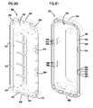
- FIG. 1is a first perspective view of a fiber access terminal according to the present invention.
- FIG. 2is a second perspective view of the fiber access terminal of FIG. 1 .
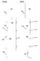
- FIG. 3is a first side view of the fiber access terminal of FIG. 1 .
- FIG. 4is a second side view of the fiber access terminal of FIG. 1 , offset approximately ninety degrees from the side view of FIG. 3 .
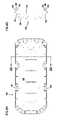
- FIG. 5is a top end view of the fiber access terminal of FIG. 1 .
- FIG. 6is a base end view of the fiber access terminal of FIG. 1 .
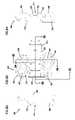
- FIG. 7is a first perspective view of a terminal body of the fiber access terminal of FIG. 1 , from a base end of the terminal body.
- FIG. 8is a second perspective view of the terminal body of FIG. 7 , showing more of the base of the terminal body.
- FIG. 9is a third perspective view of the terminal body of FIG. 7 , from a top opposite the base.
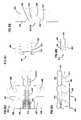
- FIG. 10is a first side view of the terminal body of FIG. 7 .
- FIG. 11is a second side view of the terminal body of FIG. 7 , offset approximately ninety degrees from the side view of FIG. 9 .
- FIG. 12is a top end view of the terminal body of FIG. 7 .
- FIG. 13is a base end view of the terminal body of FIG. 7 .
- FIG. 14is a perspective view of a second embodiment of a fiber access terminal according to the present invention.
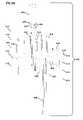
- FIG. 15is an exploded perspective view of the fiber access terminal of FIG. 14 .
- FIG. 16is a first side view of the fiber access terminal of FIG. 14 .
- FIG. 17is a second side view of the fiber access terminal of FIG. 14 , offset approximately ninety degrees from the side view of FIG. 16 .
- FIG. 18is a third side view of the fiber access terminal of FIG. 14 , opposite the side view of FIG. 17 .
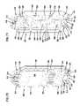
- FIG. 19is a top end view of the fiber access terminal of FIG. 14 .
- FIG. 20is a base end view of the fiber access terminal of FIG. 14 .
- FIG. 21is a first perspective view of a terminal body of the fiber access terminal of FIG. 14 .
- FIG. 22is a second perspective view of the terminal body of FIG. 21 .
- FIG. 23is a first side view of the terminal body of FIG. 21 .
- FIG. 24is a second side view of the terminal body of FIG. 21 , opposite the side view of FIG. 23 .
- FIG. 25is a perspective view of a terminal mount with the fiber access terminal of FIG. 13 mounted.
- FIG. 26is a front view of the terminal mount of FIG. 25 .
- FIG. 27is a front view of a third embodiment of a fiber access terminal according to the present invention, with a fiber distribution cable entering the terminal through a base.
- FIG. 28is a front view of the terminal of FIG. 27 , with the cover open and the fiber distribution cable extending within the interior of the terminal.
- FIG. 29is a perspective view of the terminal of FIG. 28 .
- FIG. 30is a side view of the terminal of FIG. 27 , offset approximately ninety degrees from the side view of FIG. 27 , without the fiber distribution cable.
- FIG. 31is an end view of the base of the terminal of FIG. 30 .
- FIG. 32is an end view of a top of the terminal of FIG. 30 .
- FIG. 33is a perspective view of a back of the terminal of FIG. 30 .
- FIG. 34is a perspective view of the side of the terminal of FIG. 30 .
- FIG. 35is a perspective view of the front of the terminal of FIG. 30 .
- FIG. 36is a second perspective view of the back of the terminal of FIG. 33 .
- FIG. 37is a perspective view of a second side of the terminal of FIG. 30 .
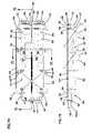
- FIG. 38is a front view of the terminal of FIG. 30 , with the cover open to show the interior of the terminal.
- FIG. 39is a side view of the terminal of FIG. 38 .
- FIG. 40is an end view of the base of the terminal of FIG. 38 .
- FIG. 41is an end view of the top of the terminal of FIG. 38 .
- FIG. 42is a front perspective view of the terminal of FIG. 38 .
- FIG. 43is a second front perspective view of the terminal of FIG. 38 .
- FIG. 44is a side perspective view of the terminal of FIG. 38 .
- FIG. 45is a second side perspective view of the terminal of FIG. 38 .
- FIG. 46is a back perspective view of the terminal of FIG. 38 .
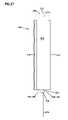
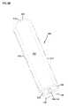
- FIG. 47is a perspective view of a fourth alternative embodiment of a fiber access terminal according to the present invention, including pedestal mounting.
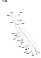
- FIGS. 48 to 51are a series of four side views of the fiber access terminal and pedestal of FIG. 47 , rotated approximately ninety degrees from each other.
- FIG. 52is a top view of the fiber access terminal and pedestal of FIG. 47 .
- FIG. 53is a bottom view of the fiber access terminal and pedestal of FIG. 47 .
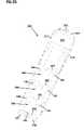
- FIG. 54is an exploded perspective view of the fiber access terminal and pedestal of FIG. 47 .
- FIG. 55is a perspective view of the fiber access terminal of FIG. 47 , removed from the pedestal.
- FIG. 56is a top view of the fiber access terminal of FIG. 55 .
- FIG. 57is a bottom view of the fiber access terminal of FIG. 55 .
- FIGS. 58 to 61are a series of four side views of the fiber access terminal and pedestal of FIG. 55 , rotated approximately ninety degrees from each other.
- FIG. 62is an exploded perspective view of the fiber access terminal of FIG. 55 , with a multi-fiber communications cable entering the bottom of the fiber access terminal and individual optical fibers directed to each of the optical fiber drop connectors.
- FIG. 63is a closer view of the multi-fiber communications cable entering the bottom of the fiber access terminal of FIG. 62 .
- FIGS. 64 to 67are a series of four side views of the fiber access terminal of FIG. 62 with the cover removed.
- FIG. 68is a top view of the fiber access terminal of FIG. 62 with the cover removed.
- FIG. 69is a bottom view of the fiber access terminal of FIG. 62 with the cover removed.
- FIG. 70is a first perspective view of a fiber access terminal housing of a fifth alternative embodiment of a fiber access terminal according to the present invention.
- FIG. 71is a second perspective view of the fiber access terminal housing of FIG. 70 .
- FIG. 72is a view of an exterior back of the fiber access terminal housing of FIG. 70 .
- FIG. 73is a side view of the fiber access terminal housing of FIG. 70 .
- FIG. 74is a view of an interior front of the fiber access terminal housing of FIG. 70 .
- FIG. 75is a cross-sectional view of the fiber access terminal of FIG. 70 , taken along line 75 - 75 of FIG. 74 .
- FIG. 76is a closer view of connector mounting locations of the fiber access terminal housing of FIG. 70 .
- FIG. 77is a base end cross-sectional view of the fiber access terminal housing of FIG. 70 , taken along line 77 - 77 of FIG. 74 .
- FIG. 78is a top end view of the fiber access terminal housing of FIG. 70 , with a partial cross-sectional view taken along line 78 - 78 in FIG. 72 .
- FIG. 79is a base end view of the fiber access terminal housing of FIG. 70 with a partial cross-sectional view taken along line 79 - 79 in FIG. 72 .
- FIG. 80is a first perspective view of a cover for use with the fiber access terminal housing of FIG. 70 .
- FIG. 81is a second perspective view of the cover of FIG. 80 .
- FIG. 82is a view of an interior front of the cover of FIG. 80 .
- FIG. 83is a side view of the cover of FIG. 80 , with a partial cross-sectional view taken along line 83 - 83 in FIG. 82 .
- FIG. 84is a view of an exterior back of the cover of FIG. 80 .
- FIG. 85is a cross-sectional base end view of the cover of FIG. 80 , taken along line 85 - 85 in FIG. 84 .
- FIG. 86is a partially exploded view of the fiber access terminal housing of FIG. 70 , with a portion of the threaded fastener inserts exploded.
- FIG. 87is a closer view of one end of the fiber access terminal of FIG. 86 , showing two of the threaded fastener inserts exploded.
- FIG. 88is a cross-sectional view of one of the threaded fastener inserts positioned within an opening of the fiber access terminal housing of FIG. 86 .
- FIG. 89is a perspective view of the interior front of the fiber access terminal housing of FIG. 70 , with three ruggedized fiber connectors mounted within mounting openings of the housing and a fourth fiber connector exploded from another mounting opening.
- FIG. 90is a first perspective view of a cable clamp halve for use with the fiber access housing of FIG. 70 and the cover of FIG. 80 .
- FIG. 91is a second perspective view of the cable clamp of FIG. 90 .
- FIG. 92is a side view of an outer side of the cable clamp of FIG. 90 .
- FIG. 93is a side view of an inner side of the cable clamp of FIG. 90 .
- FIG. 94is an end cross-sectional view of the cable clamp of FIG. 90 , taken along line 94 - 94 of FIG. 92 .
- FIG. 95is an end partial cross-sectional view of the cable clamp of FIG. 90 , taken along line 95 - 95 of FIG. 92 .
- FIG. 96is a cross-sectional view of the cable clamp of FIG. 90 , taken along line 96 - 96 of FIG. 92 .
- FIG. 97is a closer view of an outer sheath clamping area of the cable clamp of FIG. 93 .
- FIG. 98is a closer view of the outer sheath clamping area of the cable clamp of FIG. 96 .
- FIG. 99is a closer view of a cable routing channel of the cable clamp of FIG. 95 .
- FIG. 100is a perspective view of a cable routing and management insert for use with the fiber access housing of FIG. 70 and the cover of FIG. 80 .
- FIG. 101is a first side of the cable routing and management insert of FIG. 100 .
- FIG. 102is an edge view of the cable routing and management insert of FIG. 100 .
- FIG. 103is a first perspective view of a fiber access terminal housing of a sixth alternative embodiment of a fiber access terminal according to the present invention.
- FIG. 104is a second perspective view of the fiber access terminal housing of FIG. 103 .
- FIG. 105is a view of an exterior back of the fiber access terminal housing of FIG. 103 .
- FIG. 106is a side view of the fiber access terminal housing of FIG. 103 .
- FIG. 107is a view of an interior front of the fiber access terminal housing of FIG. 103 .
- FIG. 108is a cross-sectional view of the fiber access terminal of FIG. 103 , taken along line 108 - 108 of FIG. 107 .
- FIG. 109is a closer perspective view of connector mounting locations of the fiber access terminal housing of FIG. 103 .
- FIG. 110is a base end view of the fiber access terminal housing of FIG. 103 .
- FIG. 111is a top end view of the fiber access terminal housing of FIG. 103 , with a partial cross-sectional view taken along line 111 - 111 in FIG. 105 .
- FIG. 112is a base end view of the fiber access terminal housing of FIG. 103 , with a partial cross-sectional view taken along line 112 - 112 in FIG. 105 .
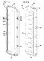
- FIG. 113is a first perspective view of a cover for use with the fiber access terminal housing of FIG. 103 .
- FIG. 114is a second perspective view of the cover of FIG. 113 .
- FIG. 115is a view of an interior front of the cover of FIG. 113 .
- FIG. 116is a side view of the cover of FIG. 113 , with a partial cross-sectional view taken along line 116 - 116 in FIG. 115 .
- FIG. 117is a view of an exterior back of the cover of FIG. 113 .
- FIG. 118is a cross-sectional base end view of the cover of FIG. 113 , taken along line 118 - 118 in FIG. 117 .
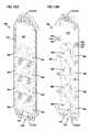
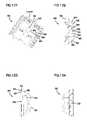
- FIG. 119is a is a perspective view of a cable routing and management insert for use with the fiber access housing of FIG. 103 and the cover of FIG. 113 .
- FIG. 120is a first side of the cable routing and management insert of FIG. 119 .
- FIG. 121is an edge view of the cable routing and management insert of FIG. 119 .
- FIG. 122is a base end view of the cable routing and management insert of FIG. 119 .
- FIG. 123is a perspective view of the cable routing and management insert of FIG. 119 , with a multi-fiber fiber optic cable partially installed and routed about the insert.
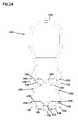
- FIG. 124is a closer view of a top end of the cable routing and management insert of FIG. 123 , with a cable fanout mounted to the insert.
- FIG. 125is a first perspective view of a fiber access terminal housing of a seventh alternative embodiment of a fiber access terminal according to the present invention.
- FIG. 126is a second perspective view of the fiber access terminal housing of FIG. 125 .
- FIG. 127is a view of an exterior back of the fiber access terminal housing of FIG. 125 .
- FIG. 128is a side view of the fiber access terminal housing of FIG. 125 .
- FIG. 129is a view of an interior front of the fiber access terminal housing of FIG. 125 .
- FIG. 130is a cross-sectional view of the fiber access terminal of FIG. 125 , taken along line 130 - 130 of FIG. 129 .
- FIG. 131is a closer perspective view of connector mounting locations of the fiber access terminal housing of FIG. 125 .
- FIG. 132is a base end view of the fiber access terminal housing of FIG. 125 .
- FIG. 133is a top end view of the fiber access terminal housing of FIG. 125 , with a partial cross-sectional view taken along line 133 - 133 in FIG. 127 .
- FIG. 134is a base end view of the fiber access terminal housing of FIG. 125 , with a partial cross-sectional view taken along line 134 - 134 in FIG. 127 .
- FIG. 135is a first perspective view of a cover for use with the fiber access terminal housing of FIG. 125 .
- FIG. 136is a second perspective view of the cover of FIG. 135 .
- FIG. 137is a view of an exterior back of the cover of FIG. 135 .
- FIG. 138is a view of an interior front of the cover of FIG. 135 .
- FIG. 139is a side view of the cover of FIG. 135 .
- FIG. 140is base end view of the cover of FIG. 135 .
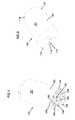
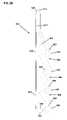
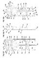
- FIGS. 1 to 4show a fiber access terminal 100 for mounting to a fiber distribution cable.
- Terminal 100includes a cover 102 and a housing 104 .
- Housing 104includes a central distribution cable entry fitting 106 and a plurality of fiber optic connectors 108 extending through housing 104 .
- Cover 102includes a top end 110 with a tab 112 .
- Tab 112is configured to permit a pull-through rope, cable or wire to be attached to terminal 100 for pulling terminal 100 through a conduit.
- An opening 114 in tab 112is provided for attaching the pull through.
- terminal 100is configured to receive a single fiber distribution cable and connect to up to eight fiber drop cables. These cables would extend to housing 104 of terminal 100 , accessible through an open bottom end 116 of cover 102 .
- Cover 102includes a pair of fastener openings 118 positioned adjacent bottom end 116 extending through a cylindrical side wall 120 . Openings 118 receive fasteners to releasably hold cover 102 about base 104 while allowing access into an interior of terminal 100 .
- FIG. 5shows top end 110 of terminal 100 with tab 112 centrally positioned.
- FIG. 6shows housing 104 positioned within cover 102 with distribution cable fitting 106 centrally located and fiber optic cable connectors 108 evenly spaced about housing 104 around fitting 106 .
- housing 104includes a base 122 through which fitting 106 and cable connectors 108 extend.
- Each of the cable connectors 108includes a first or inner end 138 and a second or outer end 136 and extends through a connector opening in base 122 (connector openings are not visible as they are occluded by connectors 108 ). Both ends 136 and 138 are configured to receive and mate with a fiber optic cable connector.
- Fitting 106defines an opening 144 also extending through base 122 of base 104 so that a fiber distribution cable may pass through base 122 into an interior of defined about an inner structure 124 of terminal 100 by cover 102 .
- Inner structure 124includes a top end 126 which is positioned within cover 102 adjacent top end 110 .
- About base 122is a circumferential wall 128 sized to fit within cover 102 and fit closely with an inner wall of cover 102 adjacent bottom end 116 .
- At least one seal, such as o-rings 130are positioned about base 104 to provide a weather-tight seal between cover 102 and base 104 .
- Extending through circumferential wall 128is a pair of openings 134 for receiving fasteners extending through openings 118 of cover 102 . Openings 134 are formed through a pair of fastener bosses 132 , providing additional material for the fasteners to extend within.
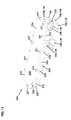
- On a bulkhead 146 of inner structure 124 between base 122 and top 126are plurality of cable routing guides 140 to provide cable slack storage and bend radius protection to fiber optic cables extending into and within terminal 100 .
- An outer wall 142extends about bulkhead 146 to help retain cables within cable guides 140 and prevent pinching or other damages to cables when cover 102 is positioned about base 104 .
- inner structure 124is a two-sided structure with similar arrangements of cable guides 140 and outer wall 142 on either side.
- a plurality of openings 148extend between the opposing sides of inner structure 124 and a plurality of cable tabs 150 of cable guides 140 are positioned adjacent each of the openings 148 . Cables passing about cable guides 140 on one side of inner structure 124 may pass through one of the openings 148 to pass about one of the cable guides 140 of the other side and then be directed to one of the inner ends 138 of connectors 108 .
- Tabs 150are provided to hold cables about cable guides 140 . Tabs 150 and openings 148 are shown positioned adjacent each other but other configurations are also anticipated.
- Inner structuremay also include a distribution cable tie-off or strain relief fixture adjacent fitting 106 so that the fiber distribution cable extending through opening 144 may be securely held within terminal 100 .
- Terminal 100is expected to be pulled through a buried conduit and mounted in a field enclosure adjacent a customer's home or business. Such a field housing may not provide a weather-tight seal or may be subject to damage allowing entry of contaminants.
- Fiber optic connectors 108are anticipated to be environmentally hardened connectors, permitting connection of fiber optic drop cables to connect to customer equipment but providing protection to the connector and connection at fiber access terminal 100 .
- Terminal 100is configured to be mounted vertically within such a field housing with top 110 of cover 102 up. The fiber distribution cable would extend out of housing 104 downward and any customer service drop cables connected to connectors 108 would also extend generally downward alongside the distribution cable. Such a configuration provides increased protection of the connectors 108 and any connections between connectors 108 and the customer service drop cables.
- terminal 200includes a cover 202 and a housing 204 having a top end 226 .
- a plurality of fasteners 231extend through a plurality of openings 234 in cover 202 and are received within fastener bosses 232 of housing 204 to releasably hold cover 202 to housing 204 .
- Extending through a base 222 of housing 204is a fiber distribution cable fitting 106 to permit passage of a fiber distribution cable through housing 204 into an interior 203 of terminal 200 .
- a plurality of fiber optic connectors 108are positioned adjacent cable fitting 106 adjacent base 222 .
- Connectors 108include inner ends 138 and outer ends 136 . As shown, within each connector 108 is a fiber optic adapter 236 . Positioned within each of inner ends 138 in fiber optic adapter 236 is a cable connector 238 .
- the fiber optic distribution cable entering interior 203 through fitting 106may be a multistrand cable and each of the individual optical fibers may be broken out of the distribution cable within interior 203 . These individual optical fibers may be routed within interior 203 about a cable guide 240 positioned adjacent top end 226 and may be terminated by cable connector 238 . Such break-outs and terminations are well known in the telecommunications industry.
- Cable guide 240may include one or more tabs 250 to aid in keeping optical fiber cables within interior 203 in the desired position to slack storage and bend radius protection.
- a wall 242extends around housing 204 and includes an upper edge 229 .
- Upper edge 229is preferably defines a plane so that cover 202 can mate closely with housing 204 .
- a sealsuch as a gasket 230 (not shown in the FIGS.) may be positioned between upper edge 229 and cover 202 to aid in forming a weathertight seal for interior 203 .
- fitting 106includes opening 144 extending through base 222 into interior 203 to permit entry of the fiber distribution cable.
- four of the eight connectors 108are visible and are arranged in a semicircle about fitting 106 . These four connectors 108 are mounted through mounting surfaces 258 positioned about base 222 .
- Outer end 136 of each of the visible connectors 108is angled radially with respect to opening 144 and fitting 106 . This angling of those connectors 108 closest to fitting 106 can be seen in FIGS. 21 to 24 , and aids in access to the outer ends 136 for connecting fiber optic drop cables to provide a service connection between a customer and the fiber distribution cable.
- the other four connectors 108are similarly arranged in a semi-circle and are angled outward, although they are positioned between base 222 and top end 226 .
- a narrowed waist area 260is provided in housing 204 so that these second set of four connectors may be positioned as desired and not increase the overall width of terminal 200 .
- terminal 200is configured to be passed through a buried conduit to extend fiber optic connectivity between a fiber distribution terminal and a fiber access terminal. As many of these conduits are limited in diameter, it is desirable that housing 204 provide an arrangement of connectors 108 that improves access for connecting drop cables while not unduly increasing the overall width of terminal 200 .
- Waist area 260provides mounting surfaces 262 for the set of four connectors 108 offset from base 222 and insets these four connectors 108 to approximately the same width as the four connectors 108 mounted to surfaces 258 .
- FIGS. 25 and 26illustrate the mounting of terminal 200 within a terminal mount 270 extending upward from a mounting base 272 to a top 280 .
- Terminal 200is mounted to an inner bulkhead 271 to which are also mounted a plurality of cable routing guides 274 to provide for bend radius protection and cable slack storage which may be used for a multi-fiber distribution cable 276 or a plurality of customer drop cables 278 .
- fitting 106 and connectors 108are positioned downward to prevent contaminants from falling in.
- terminal mount 270By directing all cables 276 and 278 to terminal 200 from the same direction, that is, from beneath toward base 222 , cable management within terminal mount 270 may be simplified. It is anticipated that terminal mount 270 could be adapted and configured for use with terminal 100 , described above, as well as with the alternative embodiments of fiber access terminals described below.
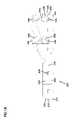
- FIGS. 27 to 29illustrate a third alternative embodiment 300 of a fiber access terminal according to the present invention, with a fiber distribution cable 276 extending through fitting 106 in a base 322 .
- Terminal 300includes a cover 302 and a housing 304 defining an interior 303 when closed about a hinge 316 , as shown in FIG. 27 .
- cover 302has been rotated about hinge 316 to expose interior 303 .
- a catch 317may be included along a side opposite hinge 316 to releasably hold cover 302 to housing 304 about interior 303 .
- Cable 276is a multi-strand cable broken out into individual optical fiber cables 310 which are routed about cable guides 340 and are terminated with cable connectors 238 and connected to inner ends 138 of connectors 108 .
- cable 276may have more optic fibers than connectors 108 of terminal 300 . These additional fibers may or may not pre-terminated and may be broken out and kept available within interior 303 . These additional fibers would then be available to use as a replacement connection should one of the other fiber cables 310 or cable connectors 238 be damaged. If these additional fibers are not pre-terminated with connectors 238 , they can be field spliced to a connector 238 . Splice block 308 is provided within interior 303 to hold and protect such splices if they are needed.
- housing 304includes a plurality of mounting faces 358 , 359 , 362 and 363 , for mounting connectors 108 . Between the mounting faces are narrowed waist areas 360 which serve a similar role to waist area 260 , described above. Connectors 108 are angled out with respect to fitting 106 but are similarly configured to terminal 200 , pointed down to receive cables 278 .
- FIGS. 31 and 32the two connectors 108 nearest base 322 occlude the remaining six connectors 108 , when viewed from base end 322 , while the two connectors 108 closest to top end 326 occlude the remaining connectors 108 when viewed from top end 326 .
- Mounting surfaces 358 , 359 , 362 and 363cooperate with waist areas 360 to ensure that outer ends 136 of connectors 108 may be angled out and accessible along housing 304 while not unduly increasing the size of terminal 300 .
- FIGS. 33 to 37provide additional views of terminal 300 with cover 302 and housing 304 closed about interior 303 .
- FIGS. 38 to 46provide additional views of terminal 300 with cover 302 hinged open about hinge 316 . Referring to FIG.
- cover 302may include a recess 338 about an inner edge and housing 304 includes a upper edge 339 .
- Recess 338 and edge 339cooperate to create a seal between cover 302 and housing 304 when terminal 300 is closed about interior 303 .
- a sealsuch as an o-ring or a gasket may be positioned within recess 338 to improve the seal.
- a pair of cable retainers 380may be provided along an inner wall 382 of housing 304 to releasably hold cables 310 which might be included within distribution cable 276 but not initially connected to one of the connectors 108 .
- cable retainers 380might be used to aid in the routing of cables 310 which are connected with one of the connectors 108 , as desired or required by a particular installation.
- FIG. 47illustrates a fourth alternative embodiment fiber access terminal and pedestal unit 402 , including a fiber access terminal 400 and a pedestal assembly 404 .
- Terminal and pedestal unit 402also includes a stake 406 and a pair of lower access door pairs 408 .
- Stake 406allows unit 402 to be used as a pedestal for mounting fiber access terminal 400 adjacent to the customer locations without the need for a separate pedestal assembly.
- Terminals 100 , 200 and 300shown above, are configured to be mounted within a separate pedestal structure, as shown in FIG. 25 , although they may also be configured similar to unit 402 to provide a common fiber access terminal and pedestal mounting unit.
- Lower access door pairs 408allow terminal 400 to be mounted above ground level for environmental protection, and still protect the fiber distribution and customer drop cables that may be connected to terminal 400 .
- FIGS. 48 to 54show additional views of terminal and pedestal unit 402 .
- Access door pairs 408are held to a pair of internal support channels 410 and 412 by fasteners 414 which include security features to deter unauthorized access to unit 402 and terminal 400 .
- the security featureis a can washer 416 positioned about each threaded fastener 414 which prevents use of standard wrenches or sockets to remove the fasteners.
- Each access door pairmay preferably include a pair of identical doors 418 , although non-identical doors may also be used.
- An upper portion of stake 406extends above the ground when stake 406 is positioned in the field.
- a pair of fasteners 420extend through upper portion 422 to mount internal support channel 412 to stake 406 .
- terminal 400might be preconfigured to terminate a fiber distribution cable, as described above with regard to terminals 100 , 200 and 300 .
- the distribution cablewould be extended from a fiber distribution terminal or pedestal to a position adjacent one or more current or future customer locations. Typically the distribution cable would be trenched and buried but other arrangements may also be used.
- stake 406may be driven into the ground to a depth required to protect against frost heave or environmentally caused movement, accidental movement or deliberate vandalism.
- the lowest mounted access door pair 408would preferably be in contact or have its lower edge recessed beneath ground level.
- a pre-terminated and connectorized customer drop cablewould be extended to a customer premises and trenched to a point adjacent unit 402 .
- One or both of the access door pairsmay be removed to provide access to terminal 400 .
- the drop cablewould be extended to the base of terminal 400 and the connector of the cable mated with one of the connectors in the base of terminal 400 .
- Thiswill optically connect the customer drop cable with one of a plurality of fiber strands of the fiber distribution cable, providing fiber optic connectivity to the customer.
- the access door pairswould then be reinstalled to unit 402 about the fiber distribution cable and any customer drop cables to protect the cables and the connectors in the base of terminal 400 .
- a base 432 of terminal 400on a base 432 of terminal 400 are a plurality of fiber optic cable connectors 424 which terminate fiber optic drop cables 428 , and a distribution cable entry fixture 426 through which a distribution cable 427 extends.
- Connectors 424 and drop cables 428are part of customer drop cables to permit connection of customer premises equipment to optical fiber within distribution cable 427 .
- Connectors 424are shown as Corning OptiTap connectors. It is anticipated that other types and styles of drop cable connectors may be used which provide some degree of environmental sealing.
- FIGS. 55 to 62show terminal 400 including a cover 434 mounted to base 432 and held in place by fasteners 431 extending through openings 452 (see FIG. 62 ) in cover 434 and received within openings 458 in base 432 .
- Alignment pins 430are also included in base 432 and are received within slots 450 in cover 434 .
- a pair of brackets 436extend from base 432 to be attached to an upper end of channels 410 and 412 . The connection of channels 410 and 412 to base 432 ties pedestal assembly 404 to terminal 400 to form unit 402 .
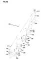
- an inner structure 454including a cable slack storage spool 444 extending from both sides of structure 454 .
- a cable fanout 440is mounted to inner structure 454 adjacent cable entry fixture 426 .
- Distribution cable 427includes a plurality of optical fibers. Once distribution cable 427 has passed through cable entry fixture 426 , a cable clamp 442 is provided to tie off cable 427 and any linear strength members included in cable 427 to inner structure 454 .
- Within distribution cable 427are a plurality of individual optical fiber cables 456 which are separated out from distribution cable 427 within fanout 440 .
- Each spool 444is sized to provide bend radius protection to optical fiber cables 456 extending to each of a plurality of inner connector fittings 438 .
- Connectors 424 of drop cables 428attach to an outer end of inner connector fittings 438 to optical connect to optical fiber cables 456 fanned out from distribution cable 427 .
- a plurality of cable guides 446are positioned about each spool to help retain cables 456 about spools 444 .
- a pass-through opening 448is positioned in inner structure 454 above fanout 440 to permit optical fiber cables 456 to be directed to either spool 444 on either side of inner structure 454 .
- Cable entry fitting 426is a compression fitting configured to fit closely about cable 426 and seal against entry water or other contaminants through base 432 when cover 434 is in place.
- a pair of O-rings 468are positioned about base 432 to engage a lower edge of cover 434 and provide an environmental seal about the junction between base 432 and cover 434 .
- Cable clamp 442mates with a cable clamp fitting on inner structure 454 about distribution cable 427 below fanout 440 .
- Screws 443extend through cable clamp 442 and are received within openings 462 in clamp fitting 460 .
- a fiber optic adapter 439Within each inner connector fitting 438 is a fiber optic adapter 439 . While not shown in FIG. 63 , each of the fiber optic cables 456 would preferably be terminated by a fiber optic connector.
- the fiber optic connectors terminating each of the cables 456would be received within the inner end of adapter 439 and positioned to be optically connected with a customer drop cable 428 of a connector 424 when connector 424 is connected to inner connector fitting 438 .
- Cable entry opening 464 through base 432 for cable 427is sized to receive and be closed off by cable entry fitting 426 .
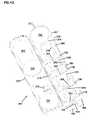
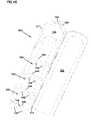
- FIGS. 64 to 69illustrate additional views of terminal 400 with cover 434 removed.
- An open portion of inner structure 454is provided above base 432 opposite the location of fanout 440 to permit passage of cables 456 from spools 444 on either side of inner structure 454 to any of the adapters 439 on terminal 400 .
- terminals 100 , 200 , 300 and 400could be configured with fewer connectors 108 similarly positioned within respect to the respective top ends and bases of the terminals.
- Terminal 300could be configured with fewer mounting surfaces if six or fewer connectors 108 are desired.
- any of the terminalscould be configured with openings or mounting surfaces for the number of connectors shown in the FIGS., above, but without the full number of connectors 108 mounted, so that additional connectors 108 could be added in the field as needed for a particular installation.
- Terminal 100could be configured with connectors 108 angled outward with respect to fitting 106 .
- a splice holdersuch as splice holder 308 may not be included in that terminal. However, it is also anticipated that a splice holder can be included within any of the terminals 100 , 200 or 300 . Tie-off or strain relief 306 of terminal 300 could be included in either of terminals 100 or 200 .
- FIGS. 70 to 102components of a fifth embodiment 500 of a fiber access terminal according to the present invention are shown, including a housing 502 and a mating cover 505 .
- Cover 505 and housing 502may be assembled to form an enclosure of terminal 500 which is similar to terminal 300 , with certain differences as may be described below. It is anticipated that certain features of terminal 300 may be incorporated into terminal 500 and vice versa.
- housing 502 of terminal 500includes a plurality of angled mounting projections 504 each having an opening 506 for receiving a ruggedized optical fiber cable connection 508 .
- connections 508are Corning Cable Systems OptiTap Connector, which includes an adapter for mating two terminated optical fibers.
- Housing 502includes a top 510 and a base 512 , and at top 512 is a pull-through tab 514 with an opening 516 to attaching a pull-through line.
- terminal 500might be pre-mounted to a fiber distribution cable such as cable 276 and pulled through a conduit to a point where desired for connection to a customer drop cable.
- a cable entry opening 528is flanked by a pair of fastener openings 530 for mounting a cable clamp, such as shown in FIGS. 90 to 99 , below.
- Fastener openings 530are in a pair of lower tabs 531 of base end 512 which are positioned generally centered with the desired cable entry path through cable entry opening 528 .
- Housing 502includes an interior side 518 which will form a portion of an interior 503 when joined up with mating cover 505 shown in FIGS. 80 to 85 , below.
- interior side 518About a perimeter of interior side 518 is a recess 520 for receiving a flat gasket 522 (shown in FIG. 89 ).
- flat gasket 522may provide improved resistance to water or other contaminant intrusion that might be caused by exposure to multiple freeze-thaw cycles.
- a plurality of fastener openings 524are positioned about the same perimeter extending through gasket 522 .
- Fastenerssuch as screws may be extended through openings 524 to secure a cover to housing 502 .
- Adjacent each opening 524are a pair of spacers 526 to set the desired maximum compression of gasket 522 and prevent over tightening which may compromise the integrity of the seal. It is anticipated that gasket 522 will extend across cable entry opening 528 and provide a seal against a plug or insert which is positioned about an entering fiber distribution cable, such as cable 276 , above. This plug is shown in FIG. 123 , below.
- mounting projections 504extend at an angle, as shown by the angling of mounting axes 536 with regard to a longitudinal axis 538 of housing 502 .
- Each pair of adjacent mounting locations 504defines a mounting face 533 which is angled toward base end 512 .
- a narrow waisted area 534is defined between the longitudinally separated pair of mounted projections 504 .
- angling of mounting projections 504allows each successive row of projections 504 to be hidden behind the adjacent rows.
- different alternative embodiments of fiber access terminals similar to terminal 500may be configured with more mounting projections without increasing the base area of the terminal.
- a recess 540 within cable entry opening 528includes an outer lip 542 and an inner lip 544 .
- the lipscooperate with a plug or insert 541 (shown in FIG. 123 , below) to provide a environmental seal within opening 528 and cooperate with gasket 522 to complete the seal between cover 505 and housing 502 .
- a generally continuous outer wall 546define an outer limit of gasket recess 520 and a plurality of spaced apart inner wall segments 548 cooperate to define an inner limit of gasket recess 520 .
- cover 505includes an interior side 550 , an exterior side 552 , a top 556 and a base 558 .
- a plurality of fastener openings 554are positioned about a perimeter of cover 505 to correspond with fastener openings 524 of housing 502 .
- Interior side 552cooperates with interior side 518 of housing 502 to form interior 503 when cover 505 is mounted to housing 502 .
- a gasket seal surface 560which corresponds to the location of gasket recess 520 of housing 502 .
- On gasket surface 560are a pair of ridges or gasket seals, an inner ridge 562 and an outer ridge 564 .
- fastener seal 566Joins to form a fastener seal 566 about each fastener opening 554 .
- fastener seal 566Within fastener seal 566 are a pair of recesses 568 which are sized to receive spacers 526 and provide a surface for spacers 526 to bottom out against.
- the engagement of recesses 568 and spacers 526set the appropriate amount of compression of gasket 522 .
- the engagementalso sets the appropriate amount of deformation of gasket 522 by ridges 562 and 564 . This set amount of deformation provides an enhanced seal against intrusion of water or other contaminants between cover 505 and housing 502 .
- a threaded insert 570may be used to reinforce openings 524 of housing 502 to provide enhanced strength and durability. It is anticipated that housing 502 may be constructed of a molded and/or machined polymeric material for reasons of economy and materials properties. Such materials may not be well suited for forming and maintaining sharp edges such as are needed to receive and secure removable fasteners such as screws within openings 524 . Threaded inserts 570 may be made of a metallic or other durable material and inserted within openings 524 to provide a sharper and more durable thread 574 to engage a screw inserted through opening 524 from opening 554 of cover 505 .
- a knurled surface 572may be provided along an exterior of each inserted 570 to aid in retention of inserts 570 within an enlarged or countersunk portion 580 or opening 524 .
- Inserts 570may have a shoulder 576 which engages a mating shoulder 578 at the base of enlarged portion 580 within opening 524 .
- Engaging insert 570 with a screw extending from one of openings 554 of cover 505 and tighteningwill tend to draw insert 570 deeper within enlarged portion 580 until shoulders 576 and 578 engage, preventing deeper insertion of insert 570 .
- the screwcan then be torqued sufficiently bring spacers 526 into engagement with recesses 568 and set the desired degree of compression and deformation of gasket 522 .
- FIG. 89illustrates housing 502 with three ruggedized connections 508 positioned within openings 506 and extending from interior side 518 through to exterior side 532 .
- a fourth connection 508is shown exploded from its position within the remaining opening 506 .
- Connections 508are composed of a plurality of components and permit closing off and sealing of openings 506 from environmental and contaminant intrusion. Among these components are an inner seal 507 and an outer o-ring 509 .
- An outer body assembly 582includes a threaded portion 584 about which is positioned outer seal 509 . Threaded portion 584 is inserted through opening 506 and is engaged by inner seal 507 and a threaded ring 586 .
- Threaded ring 586is used to draw outer body assembly 582 firmly within opening 506 so that outer seal 509 engages exterior side 532 and inner seal engages interior side 518 .
- An adapter 588is included within outer body assembly 582 and is accessible from interior side 518 to be engaged by interior fiber connector 592 .
- interior connector 592is used to terminate an optical fiber cable, such as a fiber 10
- adapter 588positions the optical fiber for optical connection with a fiber held by a connector configured mate with an outer opposite end of adapter 588 and outer body assembly 582 .
- an outer seal cap 590can be positioned in the outer opposite end of outer body assembly 582 to seal adapter 588 from external environmental intrusion.
- Gasket 522is in place in gasket recess 520 and includes openings 594 about each fastener opening 524 to accommodate spacers 526 .
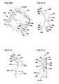
- FIGS. 90 to 99illustrate a cable clamp half 600 for use with terminal 500 .
- lowers tab 531is positioned on either side of cable entry opening 528 .
- a pair of cable clamp halves 600are placed about fiber distribution cable 276 on base end 512 .
- Each cable clamp halfincludes a body 602 and an extension 604 extending from one end of the body. Two pairs of fastener openings 606 and 607 extend through body 602 .
- recesses 608On an end of body 602 opposite extension 604 are recesses 608 which are sized and shaped to receive a corner of tabs 531 adjacent cable entry opening 528 .
- a fastener positioned through one of the openings 607will also extend through opening 530 of tab 531 and then into opening 607 of the second cable clamp half 600 . This will secure cable clamp halves 600 to tabs 531 and thus to housing 502 and to terminal 500 .
- One of each pair of openings 606 and 607includes a hex-shaped recess on an outer surface 620 . When assembled about cable 276 , an inner face 622 of each cable clamp half 600 will rest against the inner face 622 of the other half 600 .
- Extension 604includes a collar 612 and a pair of halves 600 may define a generally continuous collar.
- Collar 612may be used to attached strain relief boots or other similar devices about cable 276 passing through a cable recess 614 formed in inner face 622 .
- Cable recess 614includes a first section 616 which may sized to fit about a fiber distribution cable but not fit too closely and provide a transition for the cable into a second section 618 .
- Within second section 618are a plurality of ribs 624 which extend into opening 614 . Ribs 624 may cooperate to form a pair of first linear channel portions 626 on either side of a main channel portion 628 .
- Portions 626are sized to fit closely about linear strength members which may extend along one or both sides of cable 276 .
- Portion 628is sized to fit closely about a central tube of cable 276 where the fibers are carried. Passage through cable recesses 614 of a pair of cable clamp halves 600 attached to terminal 500 correctly positions cable 276 for entry into opening 528 and into interior 503 .
- the closeness of fit of the shapes of portions 626 and 628 about cable 276may also provide cable securing or tie-off to terminal 500 , although it is anticipated that other cable clamping or tie-off elements may be provided in terminal 500 .
- a cable routing and management insert 700for positioning within interior side 518 of housing 502 , the insert including a top end 702 and a base end 704 .
- a pair of side wall 706 and 708extend from one side of a base frame 710 to define a cable routing side 712 , with an opposite side 714 of frame 710 including structure for receiving distribution cable 276 and directing the fibers 10 within that cable to routing side 712 .
- Cable receiving side 714includes a pair of brackets 716 for holding a cable mounted device, such as fanout or a splitter mounted to the end of cable 276 .
- fibers within cable 276are separated from each other and directed into an upper portion 718 of side 714 where the fibers are directed to adjacent one of side 706 or 708 and routed through fiber pass-throughs 720 from side 714 to side 712 as the fibers extend toward top end 702 .
- fibersare routed through an upper portion 722 of cable routing structures of side 712 and redirected toward base end 704 .
- the fibersmay then be directed within a cable routing and slack storage path 724 of side 712 adjacent top end 702 defined within upper portion 722 between an inner wall 726 and outer containment structures 728 .
- path 724becomes defined between side walls 706 and 708 , and inner walls 730 and 732 , respectively.
- Retention tabs 734 positioned about path 724aid the retention of fibers within path 724 between tabs 734 and frame 710 .
- a central wall 740extends from frame 710 on side 712 , dividing a lower portion 742 into two cavities, 736 and 738 , which correspond to the number of rows of openings 506 in housing 502 .
- Central wall 740may also provided structural rigidity or strength to insert 700 to resist deflection.
- openings 744are within each cavity 736 and 738 , corresponding in position to the location of connections 508 .
- Fibersmay pass from cable path 724 into one of openings 744 so that a connector mounted to the end of such fiber may be connected to connection 508 accessible through the opening 744 .
- Fibersmay pass about a circular path of upper portion 718 of side 714 or about cable path 724 of side 712 multiple times as necessary for the amount of excess length of slack in the fiber between fiber distribution cable 276 and the particular connection 508 .
- Terminal 800is similar in most respects to terminal 500 except that terminal 800 accommodates up to eight connections 508 in eight openings 506 in angled mounting locations 504 .
- housing 504is generally the same as housing 502 .
- Each of the pairs of mounting locations 504define a mounting face 533 angled toward base end 512 with narrow waisted areas 534 between each of the mounting faces 534 and the next adjacent pair of mounting locations 504 .
- mounting openings 506include a pair of opposing flats 804 with one of the flats 804 including a key 806 .
- Flats 804 and key 806correspond to mating features of threaded portion 584 of connection 508 to correctly orient connection 508 within opening 506 and prevent connection 508 from twisting within opening 506 .
- Similar features within opening 506are shown in FIGS. 70 to 79 , above, as well as in FIGS. 125 to 134 , below.
- cover 805for joining with housing 802 to form an enclosure for fiber access terminal 800 is shown.
- Cover 805is similarly configured to cover 505 except for being longer to accommodate the added length of housing 802 as compared to housing 502 .
- the remaining elements of cover 805are essentially the same as cover 505 .
- FIGS. 119 to 122illustrate a cable routing and management insert 750 for use with housing 802 and cover 805 .
- Insert 750is similarly configured to insert 700 , with the modification that it is elongated to fit within the longer housing 802 and to provide four additional openings 744 to permit fibers to extend to and connect with the four additional connections 508 .
- FIG. 119shows cable receiving side 714 is greater detail, which includes a device receiving area between brackets 716 for receiving the splitter, fanout or other device at the end of fiber distribution cable 276 .
- a pair of outer walls 765begin adjacent device receiving area 717 and are positioned toward top end 702 with respect to device receiving area 717 .
- Outer walls 765direct fibers from the device into upper portion 718 of side 714 and into a cable path 766 defined between outer walls 765 and a plurality of outer wall segments 767 and an inner wall 769 .
- Pass-throughs 720provide for fibers to be passed from path 766 on side 714 into path 724 on side 712 .
- cable routing side 712is generally arranged similarly to side 710 of insert 700 , with extension of cable path 724 to rout to and about four additional openings 744 for passing fibers from pat 724 to connections 508 .
- intermediate turnouts 548 along path 524are provided so that different lengths of slack may be stored. Turnouts 548 provide additional cable slack storage and routing options which a single continuous loop about side 712 of insert 750 would not.
- Adjacent base end 704 , additional outer wall segments 729are included to define the outer boundary of path 724 .
- insert 750is shown with fiber distribution cable 276 extending across base end 704 to a fanout 752 positioned between brackets 716 .
- a plurality of fibers 310extend from fanout 752 and are split into two groups 754 of equal or similar numbers of fibers. One of these groups 754 is directed in path 766 clockwise about upper portion 718 and the other is directed in path 766 counter-clockwise. This split arrangement permits one half of the fibers 310 to be directed to connections 508 on one side or channel 736 of insert 750 and one half of the fibers 310 to be directed to connections 508 in the other channel 738 .
- fibers 310may be routed multiple times about path 766 to store and manage excess cable length.
- a plurality of retention tabs 770are positioned about path 766 to aid on the retention of fibers 310 within path 766 .
- FIGS. 125 to 140illustrate an eighth alternative embodiment 900 of a fiber access terminal in accordance with the present invention.
- FIGS. 125 to 134show a housing 902 which is consistent in design and function with housings 502 and 802 , above. The differences between the two housings 502 , 802 and 902 are the length of the housings and the number of mounting locations 504 and mounting openings 506 included in each embodiment. Otherwise, details of the layout of interior side 518 and exterior side 532 are essentially the same between the embodiments. Details regarding the arrangement of features and the mounting of connections 508 within openings 506 are unchanged.
- FIGS. 135 to 140show a mating cover 905 for use with housing 902 to create terminal 900 .
- Cover 905is configured generally the same as covers 505 and 805 , above, with the difference of being longer to mate with the longer housing 902 .
- interior sides 518 and 552face each other and define an interior 903 (not shown) within which cable 276 and fibers 310 are extended and directed to connections 508 mounted in openings 506 . Cable 576 would pass into the interior through cable entry opening 528 in a similar fashion as described above.
- a cable routing and management insert similar to 700 and 750may be configured for use with terminal 900 .
Landscapes
- Physics & Mathematics (AREA)
- General Physics & Mathematics (AREA)
- Optics & Photonics (AREA)
- Light Guides In General And Applications Therefor (AREA)
- Surface Treatment Of Glass Fibres Or Filaments (AREA)
- Glass Compositions (AREA)
- Yarns And Mechanical Finishing Of Yarns Or Ropes (AREA)
- Pens And Brushes (AREA)
Abstract
Description
Claims (35)
Priority Applications (3)
| Application Number | Priority Date | Filing Date | Title |
|---|---|---|---|
| US12/145,974US7539388B2 (en) | 2004-03-08 | 2008-06-25 | Fiber access terminal |
| US12/470,014US7941027B2 (en) | 2004-03-08 | 2009-05-21 | Fiber access terminal |
| US13/104,789US8363999B2 (en) | 2004-03-08 | 2011-05-10 | Fiber access terminal |
Applications Claiming Priority (6)
| Application Number | Priority Date | Filing Date | Title |
|---|---|---|---|
| US55116404P | 2004-03-08 | 2004-03-08 | |
| US60012904P | 2004-08-09 | 2004-08-09 | |
| US11/075,847US7292763B2 (en) | 2004-03-08 | 2005-03-08 | Fiber access terminal |
| US11/708,119US7397997B2 (en) | 2004-03-08 | 2007-02-15 | Fiber access terminal |
| US12/028,465US7400815B2 (en) | 2004-03-08 | 2008-02-08 | Fiber access terminal |
| US12/145,974US7539388B2 (en) | 2004-03-08 | 2008-06-25 | Fiber access terminal |
Related Parent Applications (1)
| Application Number | Title | Priority Date | Filing Date |
|---|---|---|---|
| US12/028,465ContinuationUS7400815B2 (en) | 2004-03-08 | 2008-02-08 | Fiber access terminal |
Related Child Applications (1)
| Application Number | Title | Priority Date | Filing Date |
|---|---|---|---|
| US12/470,014ContinuationUS7941027B2 (en) | 2004-03-08 | 2009-05-21 | Fiber access terminal |
Publications (2)
| Publication Number | Publication Date |
|---|---|
| US20080260345A1 US20080260345A1 (en) | 2008-10-23 |
| US7539388B2true US7539388B2 (en) | 2009-05-26 |
Family
ID=34963121
Family Applications (9)
| Application Number | Title | Priority Date | Filing Date |
|---|---|---|---|
| US11/075,847CeasedUS7292763B2 (en) | 2004-03-08 | 2005-03-08 | Fiber access terminal |
| US11/708,119Expired - LifetimeUS7397997B2 (en) | 2004-03-08 | 2007-02-15 | Fiber access terminal |
| US12/028,465Expired - LifetimeUS7400815B2 (en) | 2004-03-08 | 2008-02-08 | Fiber access terminal |
| US12/151,721Expired - LifetimeUSRE43762E1 (en) | 2004-03-08 | 2008-05-07 | Fiber access terminal |
| US12/130,337Expired - LifetimeUS7539387B2 (en) | 2004-03-08 | 2008-05-30 | Fiber access terminal |
| US12/145,951Expired - LifetimeUS7480437B2 (en) | 2004-03-08 | 2008-06-25 | Fiber access terminal |
| US12/145,974Expired - LifetimeUS7539388B2 (en) | 2004-03-08 | 2008-06-25 | Fiber access terminal |
| US12/470,014Expired - LifetimeUS7941027B2 (en) | 2004-03-08 | 2009-05-21 | Fiber access terminal |
| US13/104,789Expired - Fee RelatedUS8363999B2 (en) | 2004-03-08 | 2011-05-10 | Fiber access terminal |
Family Applications Before (6)
| Application Number | Title | Priority Date | Filing Date |
|---|---|---|---|
| US11/075,847CeasedUS7292763B2 (en) | 2004-03-08 | 2005-03-08 | Fiber access terminal |
| US11/708,119Expired - LifetimeUS7397997B2 (en) | 2004-03-08 | 2007-02-15 | Fiber access terminal |
| US12/028,465Expired - LifetimeUS7400815B2 (en) | 2004-03-08 | 2008-02-08 | Fiber access terminal |
| US12/151,721Expired - LifetimeUSRE43762E1 (en) | 2004-03-08 | 2008-05-07 | Fiber access terminal |
| US12/130,337Expired - LifetimeUS7539387B2 (en) | 2004-03-08 | 2008-05-30 | Fiber access terminal |
| US12/145,951Expired - LifetimeUS7480437B2 (en) | 2004-03-08 | 2008-06-25 | Fiber access terminal |
Family Applications After (2)
| Application Number | Title | Priority Date | Filing Date |
|---|---|---|---|
| US12/470,014Expired - LifetimeUS7941027B2 (en) | 2004-03-08 | 2009-05-21 | Fiber access terminal |
| US13/104,789Expired - Fee RelatedUS8363999B2 (en) | 2004-03-08 | 2011-05-10 | Fiber access terminal |
Country Status (8)
| Country | Link |
|---|---|
| US (9) | US7292763B2 (en) |
| EP (3) | EP1730564B1 (en) |
| AT (1) | ATE448498T1 (en) |
| AU (2) | AU2005220957B2 (en) |
| CA (1) | CA2558996A1 (en) |
| DE (1) | DE602005017594D1 (en) |
| ES (2) | ES2336224T3 (en) |
| WO (1) | WO2005088373A1 (en) |
Cited By (29)
| Publication number | Priority date | Publication date | Assignee | Title |
|---|---|---|---|---|
| US20090123115A1 (en)* | 2007-10-09 | 2009-05-14 | Erik Gronvall | Drop Terminal Releasable Engagement Mechanism |
| US7844158B2 (en) | 2007-10-09 | 2010-11-30 | Adc Telecommunications, Inc. | Mini drop terminal |
| US20110097052A1 (en)* | 2009-10-21 | 2011-04-28 | Solheid James J | Fiber Access Terminal Mounted at a Mid-Span Access Location of a Telecommunications Cable |
| US7941026B2 (en) | 2005-03-31 | 2011-05-10 | Adc Telecommunications, Inc. | Adapter block including connector storage |
| US20110235986A1 (en)* | 2010-03-24 | 2011-09-29 | Adc Telecommunications, Inc. | Optical fiber drawer with connectorized stub cable |
| US8649649B2 (en) | 2010-03-03 | 2014-02-11 | Adc Telecommunications, Inc. | Fiber distribution hub with connectorized stub cables |
| US8837940B2 (en) | 2010-04-14 | 2014-09-16 | Adc Telecommunications, Inc. | Methods and systems for distributing fiber optic telecommunication services to local areas and for supporting distributed antenna systems |
| US9078287B2 (en) | 2010-04-14 | 2015-07-07 | Adc Telecommunications, Inc. | Fiber to the antenna |
| US9106981B2 (en) | 2011-10-03 | 2015-08-11 | Tyco Electronics Uk Ltd | Aggregation enclosure for elevated, outdoor locations |
| US9952396B2 (en) | 2014-09-30 | 2018-04-24 | CommScope Connectivity Belgium BVBA | System and method of fiber distribution |
| US10031307B2 (en) | 2014-04-03 | 2018-07-24 | CommScope Connectivity Belgium BVBA | Splitter module and enclosure for use therein |
| US10042136B2 (en) | 2004-11-03 | 2018-08-07 | Commscope Technologies Llc | Fiber drop terminal |
| US10663684B2 (en) | 2016-03-23 | 2020-05-26 | CommScope Connectivity Belgium BVBA | Module and enclosure for use therein |
| US11215768B2 (en) | 2017-06-28 | 2022-01-04 | Corning Research & Development Corporation | Fiber optic connectors and connectorization employing adhesive admitting adapters |
| US11300746B2 (en) | 2017-06-28 | 2022-04-12 | Corning Research & Development Corporation | Fiber optic port module inserts, assemblies and methods of making the same |
| US11604320B2 (en) | 2020-09-30 | 2023-03-14 | Corning Research & Development Corporation | Connector assemblies for telecommunication enclosures |
| US11650388B2 (en) | 2019-11-14 | 2023-05-16 | Corning Research & Development Corporation | Fiber optic networks having a self-supporting optical terminal and methods of installing the optical terminal |
| US11668890B2 (en) | 2017-06-28 | 2023-06-06 | Corning Research & Development Corporation | Multiports and other devices having optical connection ports with securing features and methods of making the same |
| US11686913B2 (en) | 2020-11-30 | 2023-06-27 | Corning Research & Development Corporation | Fiber optic cable assemblies and connector assemblies having a crimp ring and crimp body and methods of fabricating the same |
| US11703646B2 (en) | 2017-06-28 | 2023-07-18 | Corning Research & Development Corporation | Multiports and optical connectors with rotationally discrete locking and keying features |
| US11733465B2 (en) | 2020-06-09 | 2023-08-22 | Senko Advanced Components. Inc. | Multiport assembly and associated components |
| US11880076B2 (en) | 2020-11-30 | 2024-01-23 | Corning Research & Development Corporation | Fiber optic adapter assemblies including a conversion housing and a release housing |
| US11886010B2 (en) | 2019-10-07 | 2024-01-30 | Corning Research & Development Corporation | Fiber optic terminals and fiber optic networks having variable ratio couplers |
| US11927810B2 (en) | 2020-11-30 | 2024-03-12 | Corning Research & Development Corporation | Fiber optic adapter assemblies including a conversion housing and a release member |
| US11947167B2 (en) | 2021-05-26 | 2024-04-02 | Corning Research & Development Corporation | Fiber optic terminals and tools and methods for adjusting a split ratio of a fiber optic terminal |
| US11994722B2 (en) | 2020-11-30 | 2024-05-28 | Corning Research & Development Corporation | Fiber optic adapter assemblies including an adapter housing and a locking housing |
| US12019279B2 (en) | 2019-05-31 | 2024-06-25 | Corning Research & Development Corporation | Multiports and other devices having optical connection ports with sliding actuators and methods of making the same |
| US12271040B2 (en) | 2017-06-28 | 2025-04-08 | Corning Research & Development Corporation | Fiber optic extender ports, assemblies and methods of making the same |
| US12372727B2 (en) | 2020-10-30 | 2025-07-29 | Corning Research & Development Corporation | Female fiber optic connectors having a rocker latch arm and methods of making the same |
Families Citing this family (529)
| Publication number | Priority date | Publication date | Assignee | Title |
|---|---|---|---|---|
| US6160946A (en) | 1998-07-27 | 2000-12-12 | Adc Telecommunications, Inc. | Outside plant fiber distribution apparatus and method |
| US6962445B2 (en) | 2003-09-08 | 2005-11-08 | Adc Telecommunications, Inc. | Ruggedized fiber optic connection |
| US7120347B2 (en)* | 2004-01-27 | 2006-10-10 | Corning Cable Systems Llc | Multi-port optical connection terminal |
| CA2558996A1 (en) | 2004-03-08 | 2005-09-22 | Adc Telecommunications, Inc. | Fiber access terminal |
| ES2572371T3 (en)* | 2004-11-03 | 2016-05-31 | Adc Telecommunications Inc | Fiber optic drop terminal |
| WO2006135524A2 (en) | 2005-05-18 | 2006-12-21 | Corning Cable Systems Llc | High density optical fiber distribution enclosure |
| US7284994B2 (en)* | 2005-06-21 | 2007-10-23 | Adc Telecommunications, Inc. | Grounding lug for armored cable and method |
| US7492996B2 (en)* | 2005-06-21 | 2009-02-17 | Adc Telecommunications, Inc. | Grounding device for armored cable |
| US7433570B2 (en)* | 2005-11-30 | 2008-10-07 | Tunnel Mill Polymer, Inc. | Slack storage system |
| US7308183B2 (en) | 2006-01-04 | 2007-12-11 | Adc Telecommunications, Inc. | Fiber access terminal including moisture barrier plate |
| US7477824B2 (en)* | 2006-04-05 | 2009-01-13 | Adc Telecommunications, Inc. | Universal bracket for mounting a drop terminal |
| US7760984B2 (en)* | 2006-05-04 | 2010-07-20 | Adc Telecommunications, Inc. | Fiber distribution hub with swing frame and wrap-around doors |
| FR2900740B1 (en) | 2006-05-04 | 2008-12-26 | Nexans Sa | CASING FOR LOADING AND CONNECTING OPTICAL FIBERS |
| US7330628B1 (en)* | 2006-10-23 | 2008-02-12 | Adc Telecommunications, Inc. | Fiber access terminal including moisture barrier plate with punch out |
| US7519258B2 (en) | 2006-12-21 | 2009-04-14 | Corning Cable Systems Llc | Preconnectorized fiber optic local convergence points |
| US7349616B1 (en) | 2007-01-12 | 2008-03-25 | Corning Cable Systems Llc | Fiber optic local convergence points for multiple dwelling units |
| US7400814B1 (en) | 2007-01-13 | 2008-07-15 | Furukawa Electric North America, Inc. | Wall-mountable optical fiber and cable management apparatus |
| US7572065B2 (en) | 2007-01-24 | 2009-08-11 | Adc Telecommunications, Inc. | Hardened fiber optic connector |
| US7614797B2 (en) | 2007-01-24 | 2009-11-10 | Adc Telecommunications, Inc. | Fiber optic connector mechanical interface converter |
| US7591595B2 (en) | 2007-01-24 | 2009-09-22 | Adc Telelcommunications, Inc. | Hardened fiber optic adapter |
| US7499622B2 (en)* | 2007-02-28 | 2009-03-03 | Corning Cable Systems Llc | Fiber optic drop terminals for multiple dwelling units |
| US20080221482A1 (en)* | 2007-03-06 | 2008-09-11 | Labor Saving Devices, Inc. | Steerable tip for flexible rods |
| US7558458B2 (en) | 2007-03-08 | 2009-07-07 | Adc Telecommunications, Inc. | Universal bracket for mounting a drop terminal |
| US7522805B2 (en)* | 2007-03-09 | 2009-04-21 | Adc Telecommunications, Inc. | Wall mount distribution arrangement |
| JP5289718B2 (en)* | 2007-03-12 | 2013-09-11 | 住友電気工業株式会社 | Optical wiring system |
| US7409138B1 (en) | 2007-03-12 | 2008-08-05 | Corning Cable Systems Llc | Fiber optic local convergence points for multiple dwelling units |
| US7738759B2 (en)* | 2007-03-16 | 2010-06-15 | 3M Innovative Properties Company | Optical fiber cable inlet device |
| US7512304B2 (en)* | 2007-03-23 | 2009-03-31 | Adc Telecommunications, Inc. | Drop terminal with anchor block for retaining a stub cable |
| US7664360B2 (en)* | 2007-04-17 | 2010-02-16 | Corning Cable Systems Llc | Fiber optic drop terminal mounting plate |
| US7677814B2 (en) | 2007-05-06 | 2010-03-16 | Adc Telecommunications, Inc. | Mechanical interface converter for making non-ruggedized fiber optic connectors compatible with a ruggedized fiber optic adapter |
| US7722258B2 (en) | 2007-05-06 | 2010-05-25 | Adc Telecommunications, Inc. | Interface converter for SC fiber optic connectors |
| US7715679B2 (en) | 2007-05-07 | 2010-05-11 | Adc Telecommunications, Inc. | Fiber optic enclosure with external cable spool |
| US7686519B2 (en) | 2007-06-18 | 2010-03-30 | Adc Telecommunications, Inc. | Hardened fiber optic housing and cable assembly |
| US7756379B2 (en) | 2007-08-06 | 2010-07-13 | Adc Telecommunications, Inc. | Fiber optic enclosure with internal cable spool |
| US20090046985A1 (en)* | 2007-08-16 | 2009-02-19 | Erik Gronvall | Fiber Optic Enclosure Internal Cable Management |
| US8798427B2 (en) | 2007-09-05 | 2014-08-05 | Corning Cable Systems Llc | Fiber optic terminal assembly |
| US7740409B2 (en) | 2007-09-19 | 2010-06-22 | Corning Cable Systems Llc | Multi-port optical connection terminal |
| US7762726B2 (en) | 2007-12-11 | 2010-07-27 | Adc Telecommunications, Inc. | Hardened fiber optic connection system |
| US20090208177A1 (en)* | 2007-12-12 | 2009-08-20 | Smith Trevor D | Drop terminal with optical splitter |
| US7848608B2 (en)* | 2008-02-05 | 2010-12-07 | Adc Telecommunications, Inc. | Fiber routing system with drop-in device |
| EP2283390B1 (en)* | 2008-04-21 | 2016-11-09 | ADC Telecommunications, INC. | Hardened fiber optic connector with connector body joined to cylindrical cable by unitary housing |
| US8254740B2 (en) | 2008-06-19 | 2012-08-28 | Adc Telecommunications, Inc. | Methods and systems for distributing fiber optic telecommunications services to local area |
| US8285104B2 (en)* | 2008-08-29 | 2012-10-09 | Corning Cable Systems Llc | Clip for securing a fiber optic cable assembly and associated assemblies |
| US8290333B2 (en)* | 2008-08-29 | 2012-10-16 | Corning Cable Systems Llc | Fiber optic cable assemblies with furcation bodies having features for manufacturing and methods of making the same |
| US8301004B2 (en)* | 2008-08-29 | 2012-10-30 | Corning Cable Systems Llc | Fiber optic cable assemblies employing a furcation body having anti-rotation feature |
| US11294136B2 (en) | 2008-08-29 | 2022-04-05 | Corning Optical Communications LLC | High density and bandwidth fiber optic apparatuses and related equipment and methods |
| US8452148B2 (en) | 2008-08-29 | 2013-05-28 | Corning Cable Systems Llc | Independently translatable modules and fiber optic equipment trays in fiber optic equipment |
| CN102209921B (en) | 2008-10-09 | 2015-11-25 | 康宁光缆系统有限公司 | There is the fibre-optic terminus supported from the adapter panel of the input and output optical fiber of optical splitters |
| US8879882B2 (en) | 2008-10-27 | 2014-11-04 | Corning Cable Systems Llc | Variably configurable and modular local convergence point |
| WO2010051334A1 (en)* | 2008-10-31 | 2010-05-06 | Corning Cable Systems Llc | Dual-jacket cable and transition elements and assemblies therefor |
| US7941021B2 (en)* | 2008-12-22 | 2011-05-10 | Corning Cable Systems Llc | Distribution cable assembly having mid-span access location |
| US8081857B2 (en)* | 2008-12-31 | 2011-12-20 | Opterna Am, Inc. | System for an internal rotating storage spool combined with top and bottom cable access in a fiber distribution terminal |
| US8903215B2 (en) | 2008-12-31 | 2014-12-02 | Opterna Technology Limited | Enclosure-less fiber optic terminals |
| US8170391B2 (en)* | 2009-02-11 | 2012-05-01 | Adc Telecommunications, Inc. | Fiber optic strain relief assembly |
| EP2221932B1 (en) | 2009-02-24 | 2011-11-16 | CCS Technology Inc. | Holding device for a cable or an assembly for use with a cable |
| CN106130646B (en) | 2009-03-05 | 2019-04-30 | Adc电信公司 | Methods, systems and apparatus for integrating wireless technologies into fiber optic networks |
| EP2226902A3 (en)* | 2009-03-06 | 2013-03-13 | Phitek Systems Limited | In-flight entertainment system connector |
| US20100239210A1 (en)* | 2009-03-20 | 2010-09-23 | Wakileh George I | Multipurpose Telecommunications Modules |
| EP2237091A1 (en) | 2009-03-31 | 2010-10-06 | Corning Cable Systems LLC | Removably mountable fiber optic terminal |
| US9394608B2 (en) | 2009-04-06 | 2016-07-19 | Asm America, Inc. | Semiconductor processing reactor and components thereof |
| US8412017B2 (en)* | 2009-05-13 | 2013-04-02 | Adc Telecommunications, Inc. | Cable pulling assembly |
| US8699838B2 (en) | 2009-05-14 | 2014-04-15 | Ccs Technology, Inc. | Fiber optic furcation module |
| US9075216B2 (en) | 2009-05-21 | 2015-07-07 | Corning Cable Systems Llc | Fiber optic housings configured to accommodate fiber optic modules/cassettes and fiber optic panels, and related components and methods |
| US8538226B2 (en) | 2009-05-21 | 2013-09-17 | Corning Cable Systems Llc | Fiber optic equipment guides and rails configured with stopping position(s), and related equipment and methods |
| US20100303431A1 (en)* | 2009-05-29 | 2010-12-02 | Cox Terry D | Fiber Optic Harnesses and Assemblies Facilitating Use of a Pre-Connectorized Fiber Optic Cable(s) with a Fiber Optic Terminal |
| USD620898S1 (en) | 2009-06-09 | 2010-08-03 | Adc Telecommunications, Inc. | Fiber optic terminal cover |
| USD620899S1 (en) | 2009-06-09 | 2010-08-03 | Adc Telecommunications, Inc. | Fiber optic terminal cover |
| EP2443497B1 (en) | 2009-06-19 | 2020-03-04 | Corning Cable Systems LLC | High density and bandwidth fiber optic apparatus |
| WO2010148325A1 (en) | 2009-06-19 | 2010-12-23 | Corning Cable Systems Llc | High fiber optic cable packing density apparatus |
| US8712206B2 (en) | 2009-06-19 | 2014-04-29 | Corning Cable Systems Llc | High-density fiber optic modules and module housings and related equipment |
| US7945136B2 (en)* | 2009-06-19 | 2011-05-17 | Corning Cable Systems Llc | Mounting of fiber optic cable assemblies within fiber optic shelf assemblies |
| CA2755337C (en)* | 2009-07-21 | 2015-12-15 | Afl Telecommunications Llc | Modular resealable high conductor count packaging and method |
| US8802201B2 (en) | 2009-08-14 | 2014-08-12 | Asm America, Inc. | Systems and methods for thin-film deposition of metal oxides using excited nitrogen-oxygen species |
| US8467651B2 (en) | 2009-09-30 | 2013-06-18 | Ccs Technology Inc. | Fiber optic terminals configured to dispose a fiber optic connection panel(s) within an optical fiber perimeter and related methods |
| EP2333597B1 (en)* | 2009-11-30 | 2016-09-21 | Corning Optical Communications LLC | Fiber optic module assembly and associated methods |
| US8625950B2 (en) | 2009-12-18 | 2014-01-07 | Corning Cable Systems Llc | Rotary locking apparatus for fiber optic equipment trays and related methods |
| US8992099B2 (en) | 2010-02-04 | 2015-03-31 | Corning Cable Systems Llc | Optical interface cards, assemblies, and related methods, suited for installation and use in antenna system equipment |
| US9547144B2 (en) | 2010-03-16 | 2017-01-17 | Corning Optical Communications LLC | Fiber optic distribution network for multiple dwelling units |
| US8913866B2 (en) | 2010-03-26 | 2014-12-16 | Corning Cable Systems Llc | Movable adapter panel |
| US8792767B2 (en) | 2010-04-16 | 2014-07-29 | Ccs Technology, Inc. | Distribution device |
| CA2796221C (en) | 2010-04-16 | 2018-02-13 | Ccs Technology, Inc. | Sealing and strain relief device for data cables |
| EP2381284B1 (en) | 2010-04-23 | 2014-12-31 | CCS Technology Inc. | Under floor fiber optic distribution device |
| US8879881B2 (en) | 2010-04-30 | 2014-11-04 | Corning Cable Systems Llc | Rotatable routing guide and assembly |
| US9720195B2 (en) | 2010-04-30 | 2017-08-01 | Corning Optical Communications LLC | Apparatuses and related components and methods for attachment and release of fiber optic housings to and from an equipment rack |
| US8660397B2 (en) | 2010-04-30 | 2014-02-25 | Corning Cable Systems Llc | Multi-layer module |
| US9632270B2 (en) | 2010-04-30 | 2017-04-25 | Corning Optical Communications LLC | Fiber optic housings configured for tool-less assembly, and related components and methods |
| US9075217B2 (en) | 2010-04-30 | 2015-07-07 | Corning Cable Systems Llc | Apparatuses and related components and methods for expanding capacity of fiber optic housings |
| US9519118B2 (en) | 2010-04-30 | 2016-12-13 | Corning Optical Communications LLC | Removable fiber management sections for fiber optic housings, and related components and methods |
| US8705926B2 (en) | 2010-04-30 | 2014-04-22 | Corning Optical Communications LLC | Fiber optic housings having a removable top, and related components and methods |
| US8538227B2 (en) | 2010-05-14 | 2013-09-17 | Corning Cable Systems Llc | Furcation management structures |
| AU2010355632B2 (en) | 2010-06-18 | 2014-09-18 | Adc Communications (Shanghai) Co., Ltd. | Fiber optic distribution terminal and method of deploying fiber distribution cable |
| CN110174737A (en) | 2010-06-23 | 2019-08-27 | Adc电信公司 | Telecommunication assembly |
| US8961035B2 (en) | 2010-08-02 | 2015-02-24 | Adc Telecommunications, Inc. | Architecture for a fiber optic network |
| WO2012018787A2 (en) | 2010-08-02 | 2012-02-09 | Adc Telecommunications, Inc. | Cable spool assembly |
| US8718436B2 (en) | 2010-08-30 | 2014-05-06 | Corning Cable Systems Llc | Methods, apparatuses for providing secure fiber optic connections |
| WO2012054454A2 (en) | 2010-10-19 | 2012-04-26 | Corning Cable Systems Llc | Transition box for multiple dwelling unit fiber optic distribution network |
| US8620128B2 (en)* | 2010-10-26 | 2013-12-31 | Adc Telecommunications, Inc. | System and method for anchoring fiber optic cables to provide strain relief |
| US9279951B2 (en) | 2010-10-27 | 2016-03-08 | Corning Cable Systems Llc | Fiber optic module for limited space applications having a partially sealed module sub-assembly |
| WO2012058391A1 (en) | 2010-10-28 | 2012-05-03 | Corning Cable Systems Llc | Impact resistant fiber optic enclosures and related methods |
| US8662760B2 (en) | 2010-10-29 | 2014-03-04 | Corning Cable Systems Llc | Fiber optic connector employing optical fiber guide member |
| US9116324B2 (en) | 2010-10-29 | 2015-08-25 | Corning Cable Systems Llc | Stacked fiber optic modules and fiber optic equipment configured to support stacked fiber optic modules |
| CA2819235C (en) | 2010-11-30 | 2018-01-16 | Corning Cable Systems Llc | Fiber device holder and strain relief device |
| US8873922B2 (en) | 2010-12-20 | 2014-10-28 | Adc Telecommunications, Inc. | Fan-out and parking module |
| WO2012106510A2 (en) | 2011-02-02 | 2012-08-09 | Corning Cable Systems Llc | Dense fiber optic connector assemblies and related connectors and cables suitable for establishing optical connections for optical backplanes in equipment racks |
| US8861919B2 (en)* | 2011-02-16 | 2014-10-14 | Tyco Electronics Corporation | Fiber optic closure |
| US8774585B2 (en) | 2011-04-12 | 2014-07-08 | Adc Telecommunications, Inc. | Strain-relief bracket for fiber optic closure |
| US9008485B2 (en) | 2011-05-09 | 2015-04-14 | Corning Cable Systems Llc | Attachment mechanisms employed to attach a rear housing section to a fiber optic housing, and related assemblies and methods |
| CA2877896C (en) | 2011-06-24 | 2020-07-21 | Adc Telecommunications, Inc. | Fiber termination enclosure with modular plate assemblies |
| AU2012275598A1 (en) | 2011-06-30 | 2014-01-16 | Corning Optical Communications LLC | Fiber optic equipment assemblies employing non-U-width-sized housings and related methods |
| US20130023129A1 (en) | 2011-07-20 | 2013-01-24 | Asm America, Inc. | Pressure transmitter for a semiconductor processing environment |
| US8953924B2 (en) | 2011-09-02 | 2015-02-10 | Corning Cable Systems Llc | Removable strain relief brackets for securing fiber optic cables and/or optical fibers to fiber optic equipment, and related assemblies and methods |
| CN104035167B (en) | 2011-09-28 | 2015-12-30 | 株式会社藤仓 | The manufacture method of the cable of Belt connector and the cable of Belt connector |
| US9170388B2 (en) | 2011-09-30 | 2015-10-27 | Corning Cable Systems Llc | Fiber optic ribbon cable having enhanced ribbon stack coupling and methods thereof |
| US9069151B2 (en) | 2011-10-26 | 2015-06-30 | Corning Cable Systems Llc | Composite cable breakout assembly |
| US9017481B1 (en) | 2011-10-28 | 2015-04-28 | Asm America, Inc. | Process feed management for semiconductor substrate processing |
| US8886005B2 (en) | 2012-02-13 | 2014-11-11 | Opterna Technology Limited | Adapter retaining systems |
| US8913867B2 (en) | 2011-11-21 | 2014-12-16 | Opterna Technology Limited | Fiber optic collector and terminal assemblies |
| US9038832B2 (en) | 2011-11-30 | 2015-05-26 | Corning Cable Systems Llc | Adapter panel support assembly |
| AU340165S (en)* | 2011-12-09 | 2012-01-06 | Hunter Pacific Int Pty Ltd | Electrical connector |
| AU340169S (en) | 2011-12-09 | 2012-01-06 | Hunter Pacific Int Pty Ltd | Ball joint |
| AU340168S (en) | 2011-12-09 | 2012-01-06 | Hunter Pacific Int Pty Ltd | Ceiling fan blade |
| AU340682S (en) | 2011-12-09 | 2012-01-30 | Hunter Pacific Int Pty Ltd | Mounting plate |
| AU340167S (en)* | 2011-12-09 | 2012-01-06 | Hunter Pacific Int Pty Ltd | Electrical connector |
| AU340171S (en) | 2011-12-09 | 2012-01-06 | Hunter Pacific Int Pty Ltd | Ceiling fan hub |
| US9219546B2 (en) | 2011-12-12 | 2015-12-22 | Corning Optical Communications LLC | Extremely high frequency (EHF) distributed antenna systems, and related components and methods |
| US9188760B2 (en) | 2011-12-22 | 2015-11-17 | Adc Telecommunications, Inc. | Mini rapid delivery spool |
| US10110307B2 (en) | 2012-03-02 | 2018-10-23 | Corning Optical Communications LLC | Optical network units (ONUs) for high bandwidth connectivity, and related components and methods |
| US9791653B2 (en)* | 2012-04-03 | 2017-10-17 | CommScope Connectivity Belgium BVBA | Telecommunications enclosure organizer |
| US9020321B2 (en) | 2012-04-10 | 2015-04-28 | Tyco Electronics Corporation | Wall outlet having enclosed service connection |
| US8873926B2 (en) | 2012-04-26 | 2014-10-28 | Corning Cable Systems Llc | Fiber optic enclosures employing clamping assemblies for strain relief of cables, and related assemblies and methods |
| CN102692689B (en)* | 2012-06-15 | 2013-09-25 | 华为技术有限公司 | Optical fiber terminal box |
| US9004778B2 (en) | 2012-06-29 | 2015-04-14 | Corning Cable Systems Llc | Indexable optical fiber connectors and optical fiber connector arrays |
| US9250409B2 (en) | 2012-07-02 | 2016-02-02 | Corning Cable Systems Llc | Fiber-optic-module trays and drawers for fiber-optic equipment |
| US9049500B2 (en) | 2012-08-31 | 2015-06-02 | Corning Cable Systems Llc | Fiber optic terminals, systems, and methods for network service management |
| US9042702B2 (en) | 2012-09-18 | 2015-05-26 | Corning Cable Systems Llc | Platforms and systems for fiber optic cable attachment |
| PL2717081T3 (en)* | 2012-10-02 | 2021-05-31 | Corning Research & Development Corporation | Distribution housing for optical fibers |
| US8909019B2 (en) | 2012-10-11 | 2014-12-09 | Ccs Technology, Inc. | System comprising a plurality of distribution devices and distribution device |
| US10714315B2 (en) | 2012-10-12 | 2020-07-14 | Asm Ip Holdings B.V. | Semiconductor reaction chamber showerhead |
| ES2551077T3 (en) | 2012-10-26 | 2015-11-16 | Ccs Technology, Inc. | Fiber optic management unit and fiber optic distribution device |
| ES1141660Y (en) | 2012-12-19 | 2015-10-14 | Tyco Electronics Raychem Bvba | Distribution device with incrementally added dividers |
| US20160376700A1 (en) | 2013-02-01 | 2016-12-29 | Asm Ip Holding B.V. | System for treatment of deposition reactor |
| US20140219621A1 (en)* | 2013-02-06 | 2014-08-07 | Corning Cable Systems Llc | Fiber optic multiport |
| US20150268434A1 (en)* | 2013-02-06 | 2015-09-24 | Corning Optical Communications LLC | Fiber optic multiport |
| US8985862B2 (en) | 2013-02-28 | 2015-03-24 | Corning Cable Systems Llc | High-density multi-fiber adapter housings |
| WO2014160787A1 (en)* | 2013-03-26 | 2014-10-02 | Tgs Geophysical Company (Uk) Limited | High pressure splice housing |
| US9581777B2 (en) | 2013-03-28 | 2017-02-28 | Corning Optical Communications LLC | Coupling system for fiber optic cable using folded tape |
| US11187862B2 (en) | 2013-03-28 | 2021-11-30 | Corning Optical Communications LLC | Coupling system for fiber optic cable using raised tape |
| US9344776B2 (en) | 2013-05-29 | 2016-05-17 | Go!Foton Holdings, Inc. | Patch panel tray assembly |
| US9790051B2 (en) | 2013-06-18 | 2017-10-17 | Commscope Technologies Llc | Conductor spool and optical fiber / electrical composite cable with conductor spool assembly |
| WO2014206976A1 (en) | 2013-06-27 | 2014-12-31 | Tyco Electronics Raychem Bvba | Fiber optic cable anchoring device for use with fiber optic connectors and methods of using the same |
| US9829668B2 (en) | 2013-08-23 | 2017-11-28 | CommScope Connectivity Belgium BVBA | Pass-through assembly having an anchor member and a cover |
| US11015245B2 (en) | 2014-03-19 | 2021-05-25 | Asm Ip Holding B.V. | Gas-phase reactor and system having exhaust plenum and components thereof |
| EP3132298B1 (en)* | 2014-04-14 | 2021-08-11 | CommScope Connectivity Belgium BVBA | Fiber optic enclosure with cable management drawer |
| US10858737B2 (en) | 2014-07-28 | 2020-12-08 | Asm Ip Holding B.V. | Showerhead assembly and components thereof |
| US9890456B2 (en) | 2014-08-21 | 2018-02-13 | Asm Ip Holding B.V. | Method and system for in situ formation of gas-phase compounds |
| US10976512B2 (en) | 2014-09-23 | 2021-04-13 | Ppc Broadband, Inc. | House box with mounting surface for mounted access |
| US10509187B2 (en) | 2014-09-23 | 2019-12-17 | Ppc Broadband, Inc. | Universal multi-purpose compartmentalized telecommunications box |
| US9882362B2 (en) | 2014-09-23 | 2018-01-30 | Ppc Broadband, Inc. | Enclosure for controling access to different telecommunication components |
| WO2016049242A1 (en) | 2014-09-23 | 2016-03-31 | Ppc Broadband, Inc. | Universal multi-purpose compartmentalized telecommunications box |
| US10941490B2 (en) | 2014-10-07 | 2021-03-09 | Asm Ip Holding B.V. | Multiple temperature range susceptor, assembly, reactor and system including the susceptor, and methods of using the same |
| US10054753B2 (en) | 2014-10-27 | 2018-08-21 | Commscope Technologies Llc | Fiber optic cable with flexible conduit |
| RU170465U1 (en)* | 2014-12-31 | 2017-04-25 | Алексей Валерьевич Щербинин | FIBER DISTRIBUTION TERMINAL |
| AU2016206914B2 (en)* | 2015-01-12 | 2018-04-05 | Afl Telecommunications Llc | Fiber optic terminal enclosure |
| US10317640B2 (en) | 2015-02-24 | 2019-06-11 | Commscope Technologies Llc | Indexing terminal arrangement |
| US10560211B2 (en) | 2015-02-26 | 2020-02-11 | Commscope Technologies Llc | Cable arrangement with wavelength division multiplexer |
| US10276355B2 (en) | 2015-03-12 | 2019-04-30 | Asm Ip Holding B.V. | Multi-zone reactor, system including the reactor, and method of using the same |
| CN111384691B (en) | 2015-03-16 | 2021-08-27 | 康普技术有限责任公司 | Housing for a cable distribution assembly |
| EP3311210B1 (en) | 2015-06-19 | 2022-10-12 | Commscope Technologies LLC | Optical termination enclosure |
| US10458018B2 (en) | 2015-06-26 | 2019-10-29 | Asm Ip Holding B.V. | Structures including metal carbide material, devices including the structures, and methods of forming same |
| AU2015207954C1 (en) | 2015-07-31 | 2022-05-05 | Adc Communications (Australia) Pty Limited | Cable breakout assembly |
| AU2016323386B2 (en) | 2015-09-14 | 2021-04-22 | CommScope Connectivity Belgium BVBA | Terminal enclosure with modular aspects and modules for interfacing with the terminal enclosure |
| US9851523B2 (en) | 2015-09-22 | 2017-12-26 | Go!Foton Holdings, Inc. | Apparatus for cable routing |
| US10211308B2 (en) | 2015-10-21 | 2019-02-19 | Asm Ip Holding B.V. | NbMC layers |
| WO2017083519A1 (en) | 2015-11-11 | 2017-05-18 | Afl Telecommunications Llc | Optical connection terminals for fiber optic communications networks |
| US11139308B2 (en) | 2015-12-29 | 2021-10-05 | Asm Ip Holding B.V. | Atomic layer deposition of III-V compounds to form V-NAND devices |
| WO2017120059A1 (en) | 2016-01-07 | 2017-07-13 | Commscope Technologies Llc | Flexible device for distributing hybrid cable and transitioning from trunk cable to jumper cable |
| AU2017217511A1 (en) | 2016-02-08 | 2018-07-05 | Commscope Technologies Llc | Cable slack storage system for terminal |
| US10529554B2 (en) | 2016-02-19 | 2020-01-07 | Asm Ip Holding B.V. | Method for forming silicon nitride film selectively on sidewalls or flat surfaces of trenches |
| USD876364S1 (en) | 2016-03-16 | 2020-02-25 | Commscope Technologies Llc | Cable breakout enclosure |
| USD825471S1 (en) | 2016-03-16 | 2018-08-14 | Commscope Technologies Llc | Cable breakout enclosure design |
| EP3403125B1 (en) | 2016-03-18 | 2021-07-14 | Commscope Technologies LLC | Fiber-optic cable fanout conduit arrangement and method for organizing optical fibers |
| US10343920B2 (en) | 2016-03-18 | 2019-07-09 | Asm Ip Holding B.V. | Aligned carbon nanotubes |
| US10190213B2 (en) | 2016-04-21 | 2019-01-29 | Asm Ip Holding B.V. | Deposition of metal borides |
| US10865475B2 (en) | 2016-04-21 | 2020-12-15 | Asm Ip Holding B.V. | Deposition of metal borides and silicides |
| US10367080B2 (en) | 2016-05-02 | 2019-07-30 | Asm Ip Holding B.V. | Method of forming a germanium oxynitride film |
| CN112180529B (en)* | 2016-05-23 | 2023-03-10 | 康普连通比利时私人有限公司 | Optical terminal package with reinforced self-supporting tether |
| US11453943B2 (en) | 2016-05-25 | 2022-09-27 | Asm Ip Holding B.V. | Method for forming carbon-containing silicon/metal oxide or nitride film by ALD using silicon precursor and hydrocarbon precursor |
| US10612137B2 (en) | 2016-07-08 | 2020-04-07 | Asm Ip Holdings B.V. | Organic reactants for atomic layer deposition |
| US9859151B1 (en) | 2016-07-08 | 2018-01-02 | Asm Ip Holding B.V. | Selective film deposition method to form air gaps |
| US10714385B2 (en) | 2016-07-19 | 2020-07-14 | Asm Ip Holding B.V. | Selective deposition of tungsten |
| US9887082B1 (en) | 2016-07-28 | 2018-02-06 | Asm Ip Holding B.V. | Method and apparatus for filling a gap |
| US9812320B1 (en) | 2016-07-28 | 2017-11-07 | Asm Ip Holding B.V. | Method and apparatus for filling a gap |
| KR102532607B1 (en) | 2016-07-28 | 2023-05-15 | 에이에스엠 아이피 홀딩 비.브이. | Substrate processing apparatus and method of operating the same |
| US11073670B2 (en) | 2016-08-12 | 2021-07-27 | Corning Optical Communications LLC | Device and method for sealing multiport splitters |
| US10890730B2 (en) | 2016-08-31 | 2021-01-12 | Commscope Technologies Llc | Fiber optic cable clamp and clamp assembly |
| US10606006B2 (en) | 2016-09-20 | 2020-03-31 | Clearfield, Inc. | Optical fiber distribution systems and components |
| US10859781B2 (en) | 2016-09-20 | 2020-12-08 | Clearfield, Inc. | Optical fiber distribution systems and components |
| US10164389B2 (en) | 2016-09-26 | 2018-12-25 | Commscope Technologies Llc | Breakout enclosure for transitioning from trunk cable to jumper cable |
| US10914909B2 (en) | 2016-10-13 | 2021-02-09 | Commscope Technologies Llc | Fiber optic breakout transition assembly incorporating epoxy plug and cable strain relief |
| US10355423B2 (en) | 2016-10-24 | 2019-07-16 | Commscope Technologies Llc | Hybrid connector assembly with integrated overvoltage protection |
| US10643826B2 (en) | 2016-10-26 | 2020-05-05 | Asm Ip Holdings B.V. | Methods for thermally calibrating reaction chambers |
| US11532757B2 (en) | 2016-10-27 | 2022-12-20 | Asm Ip Holding B.V. | Deposition of charge trapping layers |
| US10229833B2 (en) | 2016-11-01 | 2019-03-12 | Asm Ip Holding B.V. | Methods for forming a transition metal nitride film on a substrate by atomic layer deposition and related semiconductor device structures |
| US10714350B2 (en) | 2016-11-01 | 2020-07-14 | ASM IP Holdings, B.V. | Methods for forming a transition metal niobium nitride film on a substrate by atomic layer deposition and related semiconductor device structures |
| KR102546317B1 (en) | 2016-11-15 | 2023-06-21 | 에이에스엠 아이피 홀딩 비.브이. | Gas supply unit and substrate processing apparatus including the same |
| BR102016029000B1 (en)* | 2016-12-09 | 2022-09-13 | Furukawa Industrial S.A. Produtos Elétricos | OPTICAL TERMINATION BOX |
| KR102762543B1 (en) | 2016-12-14 | 2025-02-05 | 에이에스엠 아이피 홀딩 비.브이. | Substrate processing apparatus |
| US11581186B2 (en) | 2016-12-15 | 2023-02-14 | Asm Ip Holding B.V. | Sequential infiltration synthesis apparatus |
| US11447861B2 (en) | 2016-12-15 | 2022-09-20 | Asm Ip Holding B.V. | Sequential infiltration synthesis apparatus and a method of forming a patterned structure |
| KR102700194B1 (en) | 2016-12-19 | 2024-08-28 | 에이에스엠 아이피 홀딩 비.브이. | Substrate processing apparatus |
| US10269558B2 (en) | 2016-12-22 | 2019-04-23 | Asm Ip Holding B.V. | Method of forming a structure on a substrate |
| US10867788B2 (en) | 2016-12-28 | 2020-12-15 | Asm Ip Holding B.V. | Method of forming a structure on a substrate |
| US11390950B2 (en) | 2017-01-10 | 2022-07-19 | Asm Ip Holding B.V. | Reactor system and method to reduce residue buildup during a film deposition process |
| US10790899B2 (en) | 2017-01-12 | 2020-09-29 | Commscope Technologies Llc | Optical tapping in an indexing architecture |
| US10291969B2 (en) | 2017-02-14 | 2019-05-14 | Go!Foton Holdings, Inc. | Rear cable management |
| US10468261B2 (en) | 2017-02-15 | 2019-11-05 | Asm Ip Holding B.V. | Methods for forming a metallic film on a substrate by cyclical deposition and related semiconductor device structures |
| EP3583455A1 (en) | 2017-02-15 | 2019-12-25 | CommScope Connectivity Belgium BVBA | Interchangeable telecommunications enclosure components |
| EP3586178A4 (en) | 2017-02-27 | 2020-12-30 | CommScope, Inc. of North Carolina | Hardened converter and sealing shell for field terminated connector |
| WO2018175370A1 (en) | 2017-03-21 | 2018-09-27 | Commscope Technologies Llc | Modular breakout enclosure for transitioning from trunk cable to jumper cable |
| US10529563B2 (en) | 2017-03-29 | 2020-01-07 | Asm Ip Holdings B.V. | Method for forming doped metal oxide films on a substrate by cyclical deposition and related semiconductor device structures |
| US9977211B1 (en) | 2017-04-21 | 2018-05-22 | Afl Telecommunications Llc | Optical connection terminals for fiber optic communications networks |
| KR102457289B1 (en) | 2017-04-25 | 2022-10-21 | 에이에스엠 아이피 홀딩 비.브이. | Method for depositing a thin film and manufacturing a semiconductor device |
| WO2018197410A1 (en)* | 2017-04-25 | 2018-11-01 | CommScope Connectivity Belgium BVBA | Connection module for cable seal gel block |
| US10770286B2 (en) | 2017-05-08 | 2020-09-08 | Asm Ip Holdings B.V. | Methods for selectively forming a silicon nitride film on a substrate and related semiconductor device structures |
| CN110622051A (en) | 2017-05-08 | 2019-12-27 | 康普技术有限责任公司 | Optical fiber branch transition assembly |
| US10892156B2 (en) | 2017-05-08 | 2021-01-12 | Asm Ip Holding B.V. | Methods for forming a silicon nitride film on a substrate and related semiconductor device structures |
| US10310206B2 (en) | 2017-05-22 | 2019-06-04 | Go!Foton Holdings, Inc. | Apparatus for cable routing |
| WO2018222740A1 (en) | 2017-05-30 | 2018-12-06 | Commscope Technologies Llc | Reconfigurable optical networks |
| US10886123B2 (en) | 2017-06-02 | 2021-01-05 | Asm Ip Holding B.V. | Methods for forming low temperature semiconductor layers and related semiconductor device structures |
| MX2019014655A (en) | 2017-06-12 | 2020-02-07 | Commscope Technologies Llc | DISTRIBUTED BYPASS ARCHITECTURE THAT INCORPORATES HARD CONNECTIVITY. |
| US12040200B2 (en) | 2017-06-20 | 2024-07-16 | Asm Ip Holding B.V. | Semiconductor processing apparatus and methods for calibrating a semiconductor processing apparatus |
| US11306395B2 (en) | 2017-06-28 | 2022-04-19 | Asm Ip Holding B.V. | Methods for depositing a transition metal nitride film on a substrate by atomic layer deposition and related deposition apparatus |
| US11187859B2 (en) | 2017-06-28 | 2021-11-30 | Corning Research & Development Corporation | Fiber optic connectors and methods of making the same |
| US10502915B2 (en) | 2017-06-29 | 2019-12-10 | Commscope Technologies Llc | Device for distributing trunk cable to jumper cable |
| US10685834B2 (en) | 2017-07-05 | 2020-06-16 | Asm Ip Holdings B.V. | Methods for forming a silicon germanium tin layer and related semiconductor device structures |
| KR20190009245A (en) | 2017-07-18 | 2019-01-28 | 에이에스엠 아이피 홀딩 비.브이. | Methods for forming a semiconductor device structure and related semiconductor device structures |
| US11018002B2 (en) | 2017-07-19 | 2021-05-25 | Asm Ip Holding B.V. | Method for selectively depositing a Group IV semiconductor and related semiconductor device structures |
| US11374112B2 (en) | 2017-07-19 | 2022-06-28 | Asm Ip Holding B.V. | Method for depositing a group IV semiconductor and related semiconductor device structures |
| US10541333B2 (en) | 2017-07-19 | 2020-01-21 | Asm Ip Holding B.V. | Method for depositing a group IV semiconductor and related semiconductor device structures |
| BR112020000901A2 (en) | 2017-07-25 | 2020-07-21 | Commscope Technologies Llc | permanent fan-out arrangement |
| US10590535B2 (en) | 2017-07-26 | 2020-03-17 | Asm Ip Holdings B.V. | Chemical treatment, deposition and/or infiltration apparatus and method for using the same |
| TWI815813B (en) | 2017-08-04 | 2023-09-21 | 荷蘭商Asm智慧財產控股公司 | Showerhead assembly for distributing a gas within a reaction chamber |
| US10770336B2 (en) | 2017-08-08 | 2020-09-08 | Asm Ip Holding B.V. | Substrate lift mechanism and reactor including same |
| US10692741B2 (en) | 2017-08-08 | 2020-06-23 | Asm Ip Holdings B.V. | Radiation shield |
| US11769682B2 (en) | 2017-08-09 | 2023-09-26 | Asm Ip Holding B.V. | Storage apparatus for storing cassettes for substrates and processing apparatus equipped therewith |
| US11139191B2 (en) | 2017-08-09 | 2021-10-05 | Asm Ip Holding B.V. | Storage apparatus for storing cassettes for substrates and processing apparatus equipped therewith |
| US11002935B2 (en) | 2017-08-18 | 2021-05-11 | Commscope Technologies Llc | MST expansion closures; and methods |
| EP3673308B1 (en) | 2017-08-23 | 2024-04-03 | Commscope Technologies LLC | Drop terminal |
| USD900036S1 (en)* | 2017-08-24 | 2020-10-27 | Asm Ip Holding B.V. | Heater electrical connector and adapter |
| US11830730B2 (en) | 2017-08-29 | 2023-11-28 | Asm Ip Holding B.V. | Layer forming method and apparatus |
| KR102491945B1 (en) | 2017-08-30 | 2023-01-26 | 에이에스엠 아이피 홀딩 비.브이. | Substrate processing apparatus |
| US11056344B2 (en) | 2017-08-30 | 2021-07-06 | Asm Ip Holding B.V. | Layer forming method |
| US11295980B2 (en) | 2017-08-30 | 2022-04-05 | Asm Ip Holding B.V. | Methods for depositing a molybdenum metal film over a dielectric surface of a substrate by a cyclical deposition process and related semiconductor device structures |
| KR102401446B1 (en) | 2017-08-31 | 2022-05-24 | 에이에스엠 아이피 홀딩 비.브이. | Substrate processing apparatus |
| US10684426B2 (en) | 2017-09-08 | 2020-06-16 | Commscope Technologies Llc | Telecommunication enclosures |
| KR102630301B1 (en) | 2017-09-21 | 2024-01-29 | 에이에스엠 아이피 홀딩 비.브이. | Method of sequential infiltration synthesis treatment of infiltrateable material and structures and devices formed using same |
| US10844484B2 (en) | 2017-09-22 | 2020-11-24 | Asm Ip Holding B.V. | Apparatus for dispensing a vapor phase reactant to a reaction chamber and related methods |
| US10658205B2 (en) | 2017-09-28 | 2020-05-19 | Asm Ip Holdings B.V. | Chemical dispensing apparatus and methods for dispensing a chemical to a reaction chamber |
| US10403504B2 (en) | 2017-10-05 | 2019-09-03 | Asm Ip Holding B.V. | Method for selectively depositing a metallic film on a substrate |
| US11528079B2 (en) | 2017-10-05 | 2022-12-13 | Commscope Technologies Llc | Optical fiber testing device and method |
| US10319588B2 (en) | 2017-10-10 | 2019-06-11 | Asm Ip Holding B.V. | Method for depositing a metal chalcogenide on a substrate by cyclical deposition |
| US10923344B2 (en) | 2017-10-30 | 2021-02-16 | Asm Ip Holding B.V. | Methods for forming a semiconductor structure and related semiconductor structures |
| US10910262B2 (en) | 2017-11-16 | 2021-02-02 | Asm Ip Holding B.V. | Method of selectively depositing a capping layer structure on a semiconductor device structure |
| US11022879B2 (en) | 2017-11-24 | 2021-06-01 | Asm Ip Holding B.V. | Method of forming an enhanced unexposed photoresist layer |
| CN111344522B (en) | 2017-11-27 | 2022-04-12 | 阿斯莫Ip控股公司 | Including clean mini-environment device |
| WO2019103613A1 (en) | 2017-11-27 | 2019-05-31 | Asm Ip Holding B.V. | A storage device for storing wafer cassettes for use with a batch furnace |
| US10872771B2 (en) | 2018-01-16 | 2020-12-22 | Asm Ip Holding B. V. | Method for depositing a material film on a substrate within a reaction chamber by a cyclical deposition process and related device structures |
| KR102695659B1 (en) | 2018-01-19 | 2024-08-14 | 에이에스엠 아이피 홀딩 비.브이. | Method for depositing a gap filling layer by plasma assisted deposition |
| TWI799494B (en) | 2018-01-19 | 2023-04-21 | 荷蘭商Asm 智慧財產控股公司 | Deposition method |
| US11018047B2 (en) | 2018-01-25 | 2021-05-25 | Asm Ip Holding B.V. | Hybrid lift pin |
| USD880437S1 (en) | 2018-02-01 | 2020-04-07 | Asm Ip Holding B.V. | Gas supply plate for semiconductor manufacturing apparatus |
| US11081345B2 (en) | 2018-02-06 | 2021-08-03 | Asm Ip Holding B.V. | Method of post-deposition treatment for silicon oxide film |
| WO2019158960A1 (en) | 2018-02-14 | 2019-08-22 | Asm Ip Holding B.V. | A method for depositing a ruthenium-containing film on a substrate by a cyclical deposition process |
| US10896820B2 (en) | 2018-02-14 | 2021-01-19 | Asm Ip Holding B.V. | Method for depositing a ruthenium-containing film on a substrate by a cyclical deposition process |
| US10731249B2 (en) | 2018-02-15 | 2020-08-04 | Asm Ip Holding B.V. | Method of forming a transition metal containing film on a substrate by a cyclical deposition process, a method for supplying a transition metal halide compound to a reaction chamber, and related vapor deposition apparatus |
| KR102636427B1 (en) | 2018-02-20 | 2024-02-13 | 에이에스엠 아이피 홀딩 비.브이. | Substrate processing method and apparatus |
| US10975470B2 (en) | 2018-02-23 | 2021-04-13 | Asm Ip Holding B.V. | Apparatus for detecting or monitoring for a chemical precursor in a high temperature environment |
| US11009672B2 (en) | 2018-02-28 | 2021-05-18 | Commscope Technologies Llc | Device and method for aerially suspending an optical cable termination box |
| US11473195B2 (en) | 2018-03-01 | 2022-10-18 | Asm Ip Holding B.V. | Semiconductor processing apparatus and a method for processing a substrate |
| US11629406B2 (en) | 2018-03-09 | 2023-04-18 | Asm Ip Holding B.V. | Semiconductor processing apparatus comprising one or more pyrometers for measuring a temperature of a substrate during transfer of the substrate |
| US11114283B2 (en) | 2018-03-16 | 2021-09-07 | Asm Ip Holding B.V. | Reactor, system including the reactor, and methods of manufacturing and using same |
| US11579357B2 (en)* | 2018-03-20 | 2023-02-14 | Commscope Technologies Llc | Fiber optic cable terminal with a pushable stub cable |
| KR102646467B1 (en) | 2018-03-27 | 2024-03-11 | 에이에스엠 아이피 홀딩 비.브이. | Method of forming an electrode on a substrate and a semiconductor device structure including an electrode |
| US11088002B2 (en) | 2018-03-29 | 2021-08-10 | Asm Ip Holding B.V. | Substrate rack and a substrate processing system and method |
| US11230766B2 (en) | 2018-03-29 | 2022-01-25 | Asm Ip Holding B.V. | Substrate processing apparatus and method |
| KR102501472B1 (en) | 2018-03-30 | 2023-02-20 | 에이에스엠 아이피 홀딩 비.브이. | Substrate processing method |
| WO2019195602A1 (en) | 2018-04-06 | 2019-10-10 | Commscope Technologies Llc | Flexible organizer and self-supporting unit |
| KR102600229B1 (en) | 2018-04-09 | 2023-11-10 | 에이에스엠 아이피 홀딩 비.브이. | Substrate supporting device, substrate processing apparatus including the same and substrate processing method |
| TWI811348B (en) | 2018-05-08 | 2023-08-11 | 荷蘭商Asm 智慧財產控股公司 | Methods for depositing an oxide film on a substrate by a cyclical deposition process and related device structures |
| US12025484B2 (en) | 2018-05-08 | 2024-07-02 | Asm Ip Holding B.V. | Thin film forming method |
| US12272527B2 (en) | 2018-05-09 | 2025-04-08 | Asm Ip Holding B.V. | Apparatus for use with hydrogen radicals and method of using same |
| KR20190129718A (en) | 2018-05-11 | 2019-11-20 | 에이에스엠 아이피 홀딩 비.브이. | Methods for forming a doped metal carbide film on a substrate and related semiconductor device structures |
| KR102596988B1 (en) | 2018-05-28 | 2023-10-31 | 에이에스엠 아이피 홀딩 비.브이. | Method of processing a substrate and a device manufactured by the same |
| TWI840362B (en) | 2018-06-04 | 2024-05-01 | 荷蘭商Asm Ip私人控股有限公司 | Wafer handling chamber with moisture reduction |
| US11718913B2 (en) | 2018-06-04 | 2023-08-08 | Asm Ip Holding B.V. | Gas distribution system and reactor system including same |
| US11286562B2 (en) | 2018-06-08 | 2022-03-29 | Asm Ip Holding B.V. | Gas-phase chemical reactor and method of using same |
| US10797133B2 (en) | 2018-06-21 | 2020-10-06 | Asm Ip Holding B.V. | Method for depositing a phosphorus doped silicon arsenide film and related semiconductor device structures |
| KR102568797B1 (en) | 2018-06-21 | 2023-08-21 | 에이에스엠 아이피 홀딩 비.브이. | Substrate processing system |
| KR102854019B1 (en) | 2018-06-27 | 2025-09-02 | 에이에스엠 아이피 홀딩 비.브이. | Periodic deposition method for forming a metal-containing material and films and structures comprising the metal-containing material |
| TWI873894B (en) | 2018-06-27 | 2025-02-21 | 荷蘭商Asm Ip私人控股有限公司 | Cyclic deposition methods for forming metal-containing material and films and structures including the metal-containing material |
| US10612136B2 (en) | 2018-06-29 | 2020-04-07 | ASM IP Holding, B.V. | Temperature-controlled flange and reactor system including same |
| KR102686758B1 (en) | 2018-06-29 | 2024-07-18 | 에이에스엠 아이피 홀딩 비.브이. | Method for depositing a thin film and manufacturing a semiconductor device |
| US10388513B1 (en) | 2018-07-03 | 2019-08-20 | Asm Ip Holding B.V. | Method for depositing silicon-free carbon-containing film as gap-fill layer by pulse plasma-assisted deposition |
| US10755922B2 (en) | 2018-07-03 | 2020-08-25 | Asm Ip Holding B.V. | Method for depositing silicon-free carbon-containing film as gap-fill layer by pulse plasma-assisted deposition |
| MX2021000254A (en) | 2018-07-09 | 2021-03-25 | Commscope Technologies Llc | TELECOMMUNICATIONS TERMINAL. |
| US10767789B2 (en) | 2018-07-16 | 2020-09-08 | Asm Ip Holding B.V. | Diaphragm valves, valve components, and methods for forming valve components |
| US11053591B2 (en) | 2018-08-06 | 2021-07-06 | Asm Ip Holding B.V. | Multi-port gas injection system and reactor system including same |
| US10883175B2 (en) | 2018-08-09 | 2021-01-05 | Asm Ip Holding B.V. | Vertical furnace for processing substrates and a liner for use therein |
| US10829852B2 (en) | 2018-08-16 | 2020-11-10 | Asm Ip Holding B.V. | Gas distribution device for a wafer processing apparatus |
| US11430674B2 (en) | 2018-08-22 | 2022-08-30 | Asm Ip Holding B.V. | Sensor array, apparatus for dispensing a vapor phase reactant to a reaction chamber and related methods |
| WO2020051581A1 (en) | 2018-09-07 | 2020-03-12 | Go!Foton Holdings, Inc. | Optical fiber distribution system |
| KR102707956B1 (en) | 2018-09-11 | 2024-09-19 | 에이에스엠 아이피 홀딩 비.브이. | Method for deposition of a thin film |
| US11024523B2 (en) | 2018-09-11 | 2021-06-01 | Asm Ip Holding B.V. | Substrate processing apparatus and method |
| US11049751B2 (en) | 2018-09-14 | 2021-06-29 | Asm Ip Holding B.V. | Cassette supply system to store and handle cassettes and processing apparatus equipped therewith |
| CN110970344B (en) | 2018-10-01 | 2024-10-25 | Asmip控股有限公司 | Substrate holding apparatus, system comprising the same and method of using the same |
| US11232963B2 (en) | 2018-10-03 | 2022-01-25 | Asm Ip Holding B.V. | Substrate processing apparatus and method |
| KR102592699B1 (en) | 2018-10-08 | 2023-10-23 | 에이에스엠 아이피 홀딩 비.브이. | Substrate support unit and apparatuses for depositing thin film and processing the substrate including the same |
| US10847365B2 (en) | 2018-10-11 | 2020-11-24 | Asm Ip Holding B.V. | Method of forming conformal silicon carbide film by cyclic CVD |
| US10811256B2 (en) | 2018-10-16 | 2020-10-20 | Asm Ip Holding B.V. | Method for etching a carbon-containing feature |
| EP3867982A4 (en) | 2018-10-19 | 2022-07-13 | CommScope Technologies LLC | TELECOMMUNICATIONS TERMINAL WITH BREAK CORD |
| KR102605121B1 (en) | 2018-10-19 | 2023-11-23 | 에이에스엠 아이피 홀딩 비.브이. | Substrate processing apparatus and substrate processing method |
| KR102546322B1 (en) | 2018-10-19 | 2023-06-21 | 에이에스엠 아이피 홀딩 비.브이. | Substrate processing apparatus and substrate processing method |
| USD948463S1 (en) | 2018-10-24 | 2022-04-12 | Asm Ip Holding B.V. | Susceptor for semiconductor substrate supporting apparatus |
| US12378665B2 (en) | 2018-10-26 | 2025-08-05 | Asm Ip Holding B.V. | High temperature coatings for a preclean and etch apparatus and related methods |
| US11087997B2 (en) | 2018-10-31 | 2021-08-10 | Asm Ip Holding B.V. | Substrate processing apparatus for processing substrates |
| KR102748291B1 (en) | 2018-11-02 | 2024-12-31 | 에이에스엠 아이피 홀딩 비.브이. | Substrate support unit and substrate processing apparatus including the same |
| US11572620B2 (en) | 2018-11-06 | 2023-02-07 | Asm Ip Holding B.V. | Methods for selectively depositing an amorphous silicon film on a substrate |
| US11031242B2 (en) | 2018-11-07 | 2021-06-08 | Asm Ip Holding B.V. | Methods for depositing a boron doped silicon germanium film |
| US10847366B2 (en) | 2018-11-16 | 2020-11-24 | Asm Ip Holding B.V. | Methods for depositing a transition metal chalcogenide film on a substrate by a cyclical deposition process |
| US10818758B2 (en) | 2018-11-16 | 2020-10-27 | Asm Ip Holding B.V. | Methods for forming a metal silicate film on a substrate in a reaction chamber and related semiconductor device structures |
| US10641967B1 (en) | 2018-11-16 | 2020-05-05 | Corning Research & Development Corporation | Multiport assemblies including a modular adapter support array |
| US12040199B2 (en) | 2018-11-28 | 2024-07-16 | Asm Ip Holding B.V. | Substrate processing apparatus for processing substrates |
| US10768382B2 (en) | 2018-11-29 | 2020-09-08 | Corning Research & Development Corporation | Multiport assemblies including access apertures and a release tool |
| US11217444B2 (en) | 2018-11-30 | 2022-01-04 | Asm Ip Holding B.V. | Method for forming an ultraviolet radiation responsive metal oxide-containing film |
| KR102636428B1 (en) | 2018-12-04 | 2024-02-13 | 에이에스엠 아이피 홀딩 비.브이. | A method for cleaning a substrate processing apparatus |
| US11158513B2 (en) | 2018-12-13 | 2021-10-26 | Asm Ip Holding B.V. | Methods for forming a rhenium-containing film on a substrate by a cyclical deposition process and related semiconductor device structures |
| TWI874340B (en) | 2018-12-14 | 2025-03-01 | 荷蘭商Asm Ip私人控股有限公司 | Method of forming device structure, structure formed by the method and system for performing the method |
| PT3903136T (en) | 2018-12-28 | 2024-12-05 | Corning Res & Dev Corp | Multiport assemblies including mounting features or dust plugs |
| TWI866480B (en) | 2019-01-17 | 2024-12-11 | 荷蘭商Asm Ip 私人控股有限公司 | Methods of forming a transition metal containing film on a substrate by a cyclical deposition process |
| KR102727227B1 (en) | 2019-01-22 | 2024-11-07 | 에이에스엠 아이피 홀딩 비.브이. | Semiconductor processing device |
| CN111524788B (en) | 2019-02-01 | 2023-11-24 | Asm Ip私人控股有限公司 | Method for forming topologically selective films of silicon oxide |
| TWI845607B (en) | 2019-02-20 | 2024-06-21 | 荷蘭商Asm Ip私人控股有限公司 | Cyclical deposition method and apparatus for filling a recess formed within a substrate surface |
| KR102626263B1 (en) | 2019-02-20 | 2024-01-16 | 에이에스엠 아이피 홀딩 비.브이. | Cyclical deposition method including treatment step and apparatus for same |
| TWI838458B (en) | 2019-02-20 | 2024-04-11 | 荷蘭商Asm Ip私人控股有限公司 | Apparatus and methods for plug fill deposition in 3-d nand applications |
| TWI873122B (en) | 2019-02-20 | 2025-02-21 | 荷蘭商Asm Ip私人控股有限公司 | Method of filling a recess formed within a surface of a substrate, semiconductor structure formed according to the method, and semiconductor processing apparatus |
| TWI842826B (en) | 2019-02-22 | 2024-05-21 | 荷蘭商Asm Ip私人控股有限公司 | Substrate processing apparatus and method for processing substrate |
| MX2021010410A (en)* | 2019-03-01 | 2021-09-14 | Commscope Technologies Llc | TRACKING DEVICE FOR A TELECOMMUNICATIONS PRODUCT. |
| KR102782593B1 (en) | 2019-03-08 | 2025-03-14 | 에이에스엠 아이피 홀딩 비.브이. | Structure Including SiOC Layer and Method of Forming Same |
| KR102858005B1 (en) | 2019-03-08 | 2025-09-09 | 에이에스엠 아이피 홀딩 비.브이. | Method for Selective Deposition of Silicon Nitride Layer and Structure Including Selectively-Deposited Silicon Nitride Layer |
| US11742198B2 (en) | 2019-03-08 | 2023-08-29 | Asm Ip Holding B.V. | Structure including SiOCN layer and method of forming same |
| JP2020167398A (en) | 2019-03-28 | 2020-10-08 | エーエスエム・アイピー・ホールディング・ベー・フェー | Door openers and substrate processing equipment provided with door openers |
| US11899262B2 (en) | 2019-03-29 | 2024-02-13 | Commscope Technologies Llc | Fiber management components for telelcommunications closures |
| KR102809999B1 (en) | 2019-04-01 | 2025-05-19 | 에이에스엠 아이피 홀딩 비.브이. | Method of manufacturing semiconductor device |
| KR20200123380A (en) | 2019-04-19 | 2020-10-29 | 에이에스엠 아이피 홀딩 비.브이. | Layer forming method and apparatus |
| KR20200125453A (en) | 2019-04-24 | 2020-11-04 | 에이에스엠 아이피 홀딩 비.브이. | Gas-phase reactor system and method of using same |
| US11289326B2 (en) | 2019-05-07 | 2022-03-29 | Asm Ip Holding B.V. | Method for reforming amorphous carbon polymer film |
| EP3966615A4 (en)* | 2019-05-07 | 2023-05-03 | Sterlite Technologies Ltd | HIGH DENSITY GLASS FIBER SLEEVE |
| KR20200130121A (en) | 2019-05-07 | 2020-11-18 | 에이에스엠 아이피 홀딩 비.브이. | Chemical source vessel with dip tube |
| KR20200130652A (en) | 2019-05-10 | 2020-11-19 | 에이에스엠 아이피 홀딩 비.브이. | Method of depositing material onto a surface and structure formed according to the method |
| JP7612342B2 (en) | 2019-05-16 | 2025-01-14 | エーエスエム・アイピー・ホールディング・ベー・フェー | Wafer boat handling apparatus, vertical batch furnace and method |
| JP7598201B2 (en) | 2019-05-16 | 2024-12-11 | エーエスエム・アイピー・ホールディング・ベー・フェー | Wafer boat handling apparatus, vertical batch furnace and method |
| USD975665S1 (en) | 2019-05-17 | 2023-01-17 | Asm Ip Holding B.V. | Susceptor shaft |
| USD947913S1 (en) | 2019-05-17 | 2022-04-05 | Asm Ip Holding B.V. | Susceptor shaft |
| MX2021014036A (en) | 2019-05-18 | 2021-12-10 | Commscope Technologies Llc | Telecommunications enclosure. |
| BR112021022985A2 (en) | 2019-05-18 | 2022-01-04 | Commscope Technologies Llc | Telecommunications Cabinet System |
| USD935572S1 (en) | 2019-05-24 | 2021-11-09 | Asm Ip Holding B.V. | Gas channel plate |
| USD922229S1 (en) | 2019-06-05 | 2021-06-15 | Asm Ip Holding B.V. | Device for controlling a temperature of a gas supply unit |
| KR20200141002A (en) | 2019-06-06 | 2020-12-17 | 에이에스엠 아이피 홀딩 비.브이. | Method of using a gas-phase reactor system including analyzing exhausted gas |
| KR20200141931A (en) | 2019-06-10 | 2020-12-21 | 에이에스엠 아이피 홀딩 비.브이. | Method for cleaning quartz epitaxial chambers |
| KR20200143254A (en) | 2019-06-11 | 2020-12-23 | 에이에스엠 아이피 홀딩 비.브이. | Method of forming an electronic structure using an reforming gas, system for performing the method, and structure formed using the method |
| USD944946S1 (en) | 2019-06-14 | 2022-03-01 | Asm Ip Holding B.V. | Shower plate |
| CN112099153B (en)* | 2019-06-17 | 2025-04-01 | 泰科电子(上海)有限公司 | Connector module |
| USD931978S1 (en) | 2019-06-27 | 2021-09-28 | Asm Ip Holding B.V. | Showerhead vacuum transport |
| KR20210005515A (en) | 2019-07-03 | 2021-01-14 | 에이에스엠 아이피 홀딩 비.브이. | Temperature control assembly for substrate processing apparatus and method of using same |
| JP7499079B2 (en) | 2019-07-09 | 2024-06-13 | エーエスエム・アイピー・ホールディング・ベー・フェー | Plasma device using coaxial waveguide and substrate processing method |
| CN112216646A (en) | 2019-07-10 | 2021-01-12 | Asm Ip私人控股有限公司 | Substrate supporting assembly and substrate processing device comprising same |
| KR20210010307A (en) | 2019-07-16 | 2021-01-27 | 에이에스엠 아이피 홀딩 비.브이. | Substrate processing apparatus |
| KR20210010816A (en) | 2019-07-17 | 2021-01-28 | 에이에스엠 아이피 홀딩 비.브이. | Radical assist ignition plasma system and method |
| KR102860110B1 (en) | 2019-07-17 | 2025-09-16 | 에이에스엠 아이피 홀딩 비.브이. | Methods of forming silicon germanium structures |
| US11643724B2 (en) | 2019-07-18 | 2023-05-09 | Asm Ip Holding B.V. | Method of forming structures using a neutral beam |
| TWI839544B (en) | 2019-07-19 | 2024-04-21 | 荷蘭商Asm Ip私人控股有限公司 | Method of forming topology-controlled amorphous carbon polymer film |
| KR20210010817A (en) | 2019-07-19 | 2021-01-28 | 에이에스엠 아이피 홀딩 비.브이. | Method of Forming Topology-Controlled Amorphous Carbon Polymer Film |
| TWI851767B (en) | 2019-07-29 | 2024-08-11 | 荷蘭商Asm Ip私人控股有限公司 | Methods for selective deposition utilizing n-type dopants and/or alternative dopants to achieve high dopant incorporation |
| CN112309900A (en) | 2019-07-30 | 2021-02-02 | Asm Ip私人控股有限公司 | Substrate processing apparatus |
| CN112309899A (en) | 2019-07-30 | 2021-02-02 | Asm Ip私人控股有限公司 | Substrate processing apparatus |
| US12169361B2 (en) | 2019-07-30 | 2024-12-17 | Asm Ip Holding B.V. | Substrate processing apparatus and method |
| US11227782B2 (en) | 2019-07-31 | 2022-01-18 | Asm Ip Holding B.V. | Vertical batch furnace assembly |
| US11587814B2 (en) | 2019-07-31 | 2023-02-21 | Asm Ip Holding B.V. | Vertical batch furnace assembly |
| US11294133B2 (en) | 2019-07-31 | 2022-04-05 | Corning Research & Development Corporation | Fiber optic networks using multiports and cable assemblies with cable-to-connector orientation |
| US11587815B2 (en) | 2019-07-31 | 2023-02-21 | Asm Ip Holding B.V. | Vertical batch furnace assembly |
| CN112323048B (en) | 2019-08-05 | 2024-02-09 | Asm Ip私人控股有限公司 | Liquid level sensor for chemical source container |
| WO2021026486A1 (en) | 2019-08-08 | 2021-02-11 | Commscope Technologies Llc | Optical fiber management assembly |
| CN112342526A (en) | 2019-08-09 | 2021-02-09 | Asm Ip私人控股有限公司 | Heater assembly including cooling device and method of using same |
| USD965044S1 (en) | 2019-08-19 | 2022-09-27 | Asm Ip Holding B.V. | Susceptor shaft |
| USD965524S1 (en) | 2019-08-19 | 2022-10-04 | Asm Ip Holding B.V. | Susceptor support |
| JP2021031769A (en) | 2019-08-21 | 2021-03-01 | エーエスエム アイピー ホールディング ビー.ブイ. | Production apparatus of mixed gas of film deposition raw material and film deposition apparatus |
| USD930782S1 (en) | 2019-08-22 | 2021-09-14 | Asm Ip Holding B.V. | Gas distributor |
| USD940837S1 (en) | 2019-08-22 | 2022-01-11 | Asm Ip Holding B.V. | Electrode |
| USD949319S1 (en) | 2019-08-22 | 2022-04-19 | Asm Ip Holding B.V. | Exhaust duct |
| USD979506S1 (en) | 2019-08-22 | 2023-02-28 | Asm Ip Holding B.V. | Insulator |
| KR20210024423A (en) | 2019-08-22 | 2021-03-05 | 에이에스엠 아이피 홀딩 비.브이. | Method for forming a structure with a hole |
| US11286558B2 (en) | 2019-08-23 | 2022-03-29 | Asm Ip Holding B.V. | Methods for depositing a molybdenum nitride film on a surface of a substrate by a cyclical deposition process and related semiconductor device structures including a molybdenum nitride film |
| KR20210024420A (en) | 2019-08-23 | 2021-03-05 | 에이에스엠 아이피 홀딩 비.브이. | Method for depositing silicon oxide film having improved quality by peald using bis(diethylamino)silane |
| KR102806450B1 (en) | 2019-09-04 | 2025-05-12 | 에이에스엠 아이피 홀딩 비.브이. | Methods for selective deposition using a sacrificial capping layer |
| KR102733104B1 (en) | 2019-09-05 | 2024-11-22 | 에이에스엠 아이피 홀딩 비.브이. | Substrate processing apparatus |
| US11562901B2 (en) | 2019-09-25 | 2023-01-24 | Asm Ip Holding B.V. | Substrate processing method |
| US11487073B2 (en) | 2019-09-30 | 2022-11-01 | Corning Research & Development Corporation | Cable input devices having an integrated locking feature and assemblies using the cable input devices |
| CN112593212B (en) | 2019-10-02 | 2023-12-22 | Asm Ip私人控股有限公司 | Method for forming topologically selective silicon oxide film by cyclic plasma enhanced deposition process |
| TWI846953B (en) | 2019-10-08 | 2024-07-01 | 荷蘭商Asm Ip私人控股有限公司 | Substrate processing device |
| KR20210042810A (en) | 2019-10-08 | 2021-04-20 | 에이에스엠 아이피 홀딩 비.브이. | Reactor system including a gas distribution assembly for use with activated species and method of using same |
| TW202128273A (en) | 2019-10-08 | 2021-08-01 | 荷蘭商Asm Ip私人控股有限公司 | Gas injection system, reactor system, and method of depositing material on surface of substratewithin reaction chamber |
| US12429661B2 (en) | 2019-10-09 | 2025-09-30 | Commscope Technologies Llc | Lanyards for telecommunications equipment including ports and mating connectors |
| TWI846966B (en) | 2019-10-10 | 2024-07-01 | 荷蘭商Asm Ip私人控股有限公司 | Method of forming a photoresist underlayer and structure including same |
| US12009241B2 (en) | 2019-10-14 | 2024-06-11 | Asm Ip Holding B.V. | Vertical batch furnace assembly with detector to detect cassette |
| TWI834919B (en) | 2019-10-16 | 2024-03-11 | 荷蘭商Asm Ip私人控股有限公司 | Method of topology-selective film formation of silicon oxide |
| US11637014B2 (en) | 2019-10-17 | 2023-04-25 | Asm Ip Holding B.V. | Methods for selective deposition of doped semiconductor material |
| KR102845724B1 (en) | 2019-10-21 | 2025-08-13 | 에이에스엠 아이피 홀딩 비.브이. | Apparatus and methods for selectively etching films |
| KR20210050453A (en) | 2019-10-25 | 2021-05-07 | 에이에스엠 아이피 홀딩 비.브이. | Methods for filling a gap feature on a substrate surface and related semiconductor structures |
| US11646205B2 (en) | 2019-10-29 | 2023-05-09 | Asm Ip Holding B.V. | Methods of selectively forming n-type doped material on a surface, systems for selectively forming n-type doped material, and structures formed using same |
| KR20210054983A (en) | 2019-11-05 | 2021-05-14 | 에이에스엠 아이피 홀딩 비.브이. | Structures with doped semiconductor layers and methods and systems for forming same |
| US11501968B2 (en) | 2019-11-15 | 2022-11-15 | Asm Ip Holding B.V. | Method for providing a semiconductor device with silicon filled gaps |
| EP4062218A4 (en) | 2019-11-20 | 2024-07-03 | CommScope Technologies LLC | SYSTEM AND METHOD FOR INSERTING A FIBER OPTIC CONNECTOR HAVING AN INFLATABLE SECTION AND A NON-INFLATABLE SECTION |
| KR102861314B1 (en) | 2019-11-20 | 2025-09-17 | 에이에스엠 아이피 홀딩 비.브이. | Method of depositing carbon-containing material on a surface of a substrate, structure formed using the method, and system for forming the structure |
| CN112951697B (en) | 2019-11-26 | 2025-07-29 | Asmip私人控股有限公司 | Substrate processing apparatus |
| US11450529B2 (en) | 2019-11-26 | 2022-09-20 | Asm Ip Holding B.V. | Methods for selectively forming a target film on a substrate comprising a first dielectric surface and a second metallic surface |
| CN120432376A (en) | 2019-11-29 | 2025-08-05 | Asm Ip私人控股有限公司 | Substrate processing apparatus |
| CN112885692B (en) | 2019-11-29 | 2025-08-15 | Asmip私人控股有限公司 | Substrate processing apparatus |
| JP7527928B2 (en) | 2019-12-02 | 2024-08-05 | エーエスエム・アイピー・ホールディング・ベー・フェー | Substrate processing apparatus and substrate processing method |
| KR20210070898A (en) | 2019-12-04 | 2021-06-15 | 에이에스엠 아이피 홀딩 비.브이. | Substrate processing apparatus |
| KR20210078405A (en) | 2019-12-17 | 2021-06-28 | 에이에스엠 아이피 홀딩 비.브이. | Method of forming vanadium nitride layer and structure including the vanadium nitride layer |
| KR20210080214A (en) | 2019-12-19 | 2021-06-30 | 에이에스엠 아이피 홀딩 비.브이. | Methods for filling a gap feature on a substrate and related semiconductor structures |
| JP7730637B2 (en) | 2020-01-06 | 2025-08-28 | エーエスエム・アイピー・ホールディング・ベー・フェー | Gas delivery assembly, components thereof, and reactor system including same |
| JP7636892B2 (en) | 2020-01-06 | 2025-02-27 | エーエスエム・アイピー・ホールディング・ベー・フェー | Channeled Lift Pins |
| US11993847B2 (en) | 2020-01-08 | 2024-05-28 | Asm Ip Holding B.V. | Injector |
| KR20210093163A (en) | 2020-01-16 | 2021-07-27 | 에이에스엠 아이피 홀딩 비.브이. | Method of forming high aspect ratio features |
| KR102675856B1 (en) | 2020-01-20 | 2024-06-17 | 에이에스엠 아이피 홀딩 비.브이. | Method of forming thin film and method of modifying surface of thin film |
| TWI889744B (en) | 2020-01-29 | 2025-07-11 | 荷蘭商Asm Ip私人控股有限公司 | Contaminant trap system, and baffle plate stack |
| TW202513845A (en) | 2020-02-03 | 2025-04-01 | 荷蘭商Asm Ip私人控股有限公司 | Semiconductor structures and methods for forming the same |
| KR20210100010A (en) | 2020-02-04 | 2021-08-13 | 에이에스엠 아이피 홀딩 비.브이. | Method and apparatus for transmittance measurements of large articles |
| US11776846B2 (en) | 2020-02-07 | 2023-10-03 | Asm Ip Holding B.V. | Methods for depositing gap filling fluids and related systems and devices |
| US11536921B2 (en) | 2020-02-11 | 2022-12-27 | Corning Research & Development Corporation | Fiber optic terminals having one or more loopback assemblies |
| TW202146691A (en) | 2020-02-13 | 2021-12-16 | 荷蘭商Asm Ip私人控股有限公司 | Gas distribution assembly, shower plate assembly, and method of adjusting conductance of gas to reaction chamber |
| KR20210103956A (en) | 2020-02-13 | 2021-08-24 | 에이에스엠 아이피 홀딩 비.브이. | Substrate processing apparatus including light receiving device and calibration method of light receiving device |
| TWI855223B (en) | 2020-02-17 | 2024-09-11 | 荷蘭商Asm Ip私人控股有限公司 | Method for growing phosphorous-doped silicon layer |
| CN113410160A (en) | 2020-02-28 | 2021-09-17 | Asm Ip私人控股有限公司 | System specially used for cleaning parts |
| KR20210113043A (en) | 2020-03-04 | 2021-09-15 | 에이에스엠 아이피 홀딩 비.브이. | Alignment fixture for a reactor system |
| KR20210116240A (en) | 2020-03-11 | 2021-09-27 | 에이에스엠 아이피 홀딩 비.브이. | Substrate handling device with adjustable joints |
| US11876356B2 (en) | 2020-03-11 | 2024-01-16 | Asm Ip Holding B.V. | Lockout tagout assembly and system and method of using same |
| KR102775390B1 (en) | 2020-03-12 | 2025-02-28 | 에이에스엠 아이피 홀딩 비.브이. | Method for Fabricating Layer Structure Having Target Topological Profile |
| US12173404B2 (en) | 2020-03-17 | 2024-12-24 | Asm Ip Holding B.V. | Method of depositing epitaxial material, structure formed using the method, and system for performing the method |
| KR102755229B1 (en) | 2020-04-02 | 2025-01-14 | 에이에스엠 아이피 홀딩 비.브이. | Thin film forming method |
| TWI887376B (en) | 2020-04-03 | 2025-06-21 | 荷蘭商Asm Ip私人控股有限公司 | Method for manufacturing semiconductor device |
| TWI888525B (en) | 2020-04-08 | 2025-07-01 | 荷蘭商Asm Ip私人控股有限公司 | Apparatus and methods for selectively etching silcon oxide films |
| US11821078B2 (en) | 2020-04-15 | 2023-11-21 | Asm Ip Holding B.V. | Method for forming precoat film and method for forming silicon-containing film |
| KR20210128343A (en) | 2020-04-15 | 2021-10-26 | 에이에스엠 아이피 홀딩 비.브이. | Method of forming chromium nitride layer and structure including the chromium nitride layer |
| US11996289B2 (en) | 2020-04-16 | 2024-05-28 | Asm Ip Holding B.V. | Methods of forming structures including silicon germanium and silicon layers, devices formed using the methods, and systems for performing the methods |
| KR20210130646A (en) | 2020-04-21 | 2021-11-01 | 에이에스엠 아이피 홀딩 비.브이. | Method for processing a substrate |
| WO2021217079A1 (en) | 2020-04-24 | 2021-10-28 | Commscope Technologies Llc | Fiber routing systems and methods |
| CN113555279A (en) | 2020-04-24 | 2021-10-26 | Asm Ip私人控股有限公司 | Methods of forming vanadium nitride-containing layers and structures comprising the same |
| KR20210132600A (en) | 2020-04-24 | 2021-11-04 | 에이에스엠 아이피 홀딩 비.브이. | Methods and systems for depositing a layer comprising vanadium, nitrogen, and a further element |
| KR20210132612A (en) | 2020-04-24 | 2021-11-04 | 에이에스엠 아이피 홀딩 비.브이. | Methods and apparatus for stabilizing vanadium compounds |
| TW202208671A (en) | 2020-04-24 | 2022-03-01 | 荷蘭商Asm Ip私人控股有限公司 | Methods of forming structures including vanadium boride and vanadium phosphide layers |
| KR102866804B1 (en) | 2020-04-24 | 2025-09-30 | 에이에스엠 아이피 홀딩 비.브이. | Vertical batch furnace assembly comprising a cooling gas supply |
| KR102783898B1 (en) | 2020-04-29 | 2025-03-18 | 에이에스엠 아이피 홀딩 비.브이. | Solid source precursor vessel |
| US11460657B2 (en) | 2020-04-30 | 2022-10-04 | Commscope Technologies Llc | Fiber management system and method for a telecommunication terminal |
| US11953750B2 (en) | 2020-04-30 | 2024-04-09 | Commscope Technologies Llc | Interlocking fiber optic connector holder |
| KR20210134869A (en) | 2020-05-01 | 2021-11-11 | 에이에스엠 아이피 홀딩 비.브이. | Fast FOUP swapping with a FOUP handler |
| JP7726664B2 (en) | 2020-05-04 | 2025-08-20 | エーエスエム・アイピー・ホールディング・ベー・フェー | Substrate processing system for processing a substrate |
| KR102788543B1 (en) | 2020-05-13 | 2025-03-27 | 에이에스엠 아이피 홀딩 비.브이. | Laser alignment fixture for a reactor system |
| TW202146699A (en) | 2020-05-15 | 2021-12-16 | 荷蘭商Asm Ip私人控股有限公司 | Method of forming a silicon germanium layer, semiconductor structure, semiconductor device, method of forming a deposition layer, and deposition system |
| KR20210143653A (en) | 2020-05-19 | 2021-11-29 | 에이에스엠 아이피 홀딩 비.브이. | Substrate processing apparatus |
| CN111799582B (en)* | 2020-05-19 | 2021-09-14 | 华为技术有限公司 | Binding post and transmission equipment |
| KR102795476B1 (en) | 2020-05-21 | 2025-04-11 | 에이에스엠 아이피 홀딩 비.브이. | Structures including multiple carbon layers and methods of forming and using same |
| KR20210145079A (en) | 2020-05-21 | 2021-12-01 | 에이에스엠 아이피 홀딩 비.브이. | Flange and apparatus for processing substrates |
| TWI873343B (en) | 2020-05-22 | 2025-02-21 | 荷蘭商Asm Ip私人控股有限公司 | Reaction system for forming thin film on substrate |
| KR20210146802A (en) | 2020-05-26 | 2021-12-06 | 에이에스엠 아이피 홀딩 비.브이. | Method for depositing boron and gallium containing silicon germanium layers |
| TWI876048B (en) | 2020-05-29 | 2025-03-11 | 荷蘭商Asm Ip私人控股有限公司 | Substrate processing device |
| TW202212620A (en) | 2020-06-02 | 2022-04-01 | 荷蘭商Asm Ip私人控股有限公司 | Apparatus for processing substrate, method of forming film, and method of controlling apparatus for processing substrate |
| TW202208659A (en) | 2020-06-16 | 2022-03-01 | 荷蘭商Asm Ip私人控股有限公司 | Method for depositing boron containing silicon germanium layers |
| TW202218133A (en) | 2020-06-24 | 2022-05-01 | 荷蘭商Asm Ip私人控股有限公司 | Method for forming a layer provided with silicon |
| TWI873359B (en) | 2020-06-30 | 2025-02-21 | 荷蘭商Asm Ip私人控股有限公司 | Substrate processing method |
| US12431354B2 (en) | 2020-07-01 | 2025-09-30 | Asm Ip Holding B.V. | Silicon nitride and silicon oxide deposition methods using fluorine inhibitor |
| EP3971622A1 (en) | 2020-07-02 | 2022-03-23 | Go!Foton Holdings, Inc. | Intelligent optical switch |
| TW202202649A (en) | 2020-07-08 | 2022-01-16 | 荷蘭商Asm Ip私人控股有限公司 | Substrate processing method |
| KR20220010438A (en) | 2020-07-17 | 2022-01-25 | 에이에스엠 아이피 홀딩 비.브이. | Structures and methods for use in photolithography |
| TWI878570B (en) | 2020-07-20 | 2025-04-01 | 荷蘭商Asm Ip私人控股有限公司 | Method and system for depositing molybdenum layers |
| KR20220011092A (en) | 2020-07-20 | 2022-01-27 | 에이에스엠 아이피 홀딩 비.브이. | Method and system for forming structures including transition metal layers |
| US12322591B2 (en) | 2020-07-27 | 2025-06-03 | Asm Ip Holding B.V. | Thin film deposition process |
| KR20220021863A (en) | 2020-08-14 | 2022-02-22 | 에이에스엠 아이피 홀딩 비.브이. | Method for processing a substrate |
| US12040177B2 (en) | 2020-08-18 | 2024-07-16 | Asm Ip Holding B.V. | Methods for forming a laminate film by cyclical plasma-enhanced deposition processes |
| TW202228863A (en) | 2020-08-25 | 2022-08-01 | 荷蘭商Asm Ip私人控股有限公司 | Method for cleaning a substrate, method for selectively depositing, and reaction system |
| US11725280B2 (en) | 2020-08-26 | 2023-08-15 | Asm Ip Holding B.V. | Method for forming metal silicon oxide and metal silicon oxynitride layers |
| TW202229601A (en) | 2020-08-27 | 2022-08-01 | 荷蘭商Asm Ip私人控股有限公司 | Method of forming patterned structures, method of manipulating mechanical property, device structure, and substrate processing system |
| MX2023002442A (en)* | 2020-08-28 | 2023-03-22 | Commscope Technologies Llc | FIBER MANAGEMENT ASSEMBLY FOR MULTIPOINT TERMINAL. |
| TW202217045A (en) | 2020-09-10 | 2022-05-01 | 荷蘭商Asm Ip私人控股有限公司 | Methods for depositing gap filing fluids and related systems and devices |
| WO2022056274A1 (en) | 2020-09-11 | 2022-03-17 | Commscope Technologies Llc | Terminal enclosure |
| USD990534S1 (en) | 2020-09-11 | 2023-06-27 | Asm Ip Holding B.V. | Weighted lift pin |
| KR20220036866A (en) | 2020-09-16 | 2022-03-23 | 에이에스엠 아이피 홀딩 비.브이. | Silicon oxide deposition method |
| USD1012873S1 (en) | 2020-09-24 | 2024-01-30 | Asm Ip Holding B.V. | Electrode for semiconductor processing apparatus |
| TWI889903B (en) | 2020-09-25 | 2025-07-11 | 荷蘭商Asm Ip私人控股有限公司 | Semiconductor processing method |
| US12009224B2 (en) | 2020-09-29 | 2024-06-11 | Asm Ip Holding B.V. | Apparatus and method for etching metal nitrides |
| KR20220045900A (en) | 2020-10-06 | 2022-04-13 | 에이에스엠 아이피 홀딩 비.브이. | Deposition method and an apparatus for depositing a silicon-containing material |
| CN114293174A (en) | 2020-10-07 | 2022-04-08 | Asm Ip私人控股有限公司 | Gas supply unit and substrate processing apparatus including the same |
| TW202229613A (en) | 2020-10-14 | 2022-08-01 | 荷蘭商Asm Ip私人控股有限公司 | Method of depositing material on stepped structure |
| TW202232565A (en) | 2020-10-15 | 2022-08-16 | 荷蘭商Asm Ip私人控股有限公司 | Method of manufacturing semiconductor device, and substrate treatment apparatus using ether-cat |
| TW202217037A (en) | 2020-10-22 | 2022-05-01 | 荷蘭商Asm Ip私人控股有限公司 | Method of depositing vanadium metal, structure, device and a deposition assembly |
| TW202223136A (en) | 2020-10-28 | 2022-06-16 | 荷蘭商Asm Ip私人控股有限公司 | Method for forming layer on substrate, and semiconductor processing system |
| TW202229620A (en) | 2020-11-12 | 2022-08-01 | 特文特大學 | Deposition system, method for controlling reaction condition, method for depositing |
| TW202229795A (en) | 2020-11-23 | 2022-08-01 | 荷蘭商Asm Ip私人控股有限公司 | A substrate processing apparatus with an injector |
| US20220163731A1 (en)* | 2020-11-24 | 2022-05-26 | Corning Research & Development Corporation | Multiports and other devices having connection port inserts and methods of making the same |
| TW202235649A (en) | 2020-11-24 | 2022-09-16 | 荷蘭商Asm Ip私人控股有限公司 | Methods for filling a gap and related systems and devices |
| TW202235675A (en) | 2020-11-30 | 2022-09-16 | 荷蘭商Asm Ip私人控股有限公司 | Injector, and substrate processing apparatus |
| US12255053B2 (en) | 2020-12-10 | 2025-03-18 | Asm Ip Holding B.V. | Methods and systems for depositing a layer |
| TW202233884A (en) | 2020-12-14 | 2022-09-01 | 荷蘭商Asm Ip私人控股有限公司 | Method of forming structures for threshold voltage control |
| US11946137B2 (en) | 2020-12-16 | 2024-04-02 | Asm Ip Holding B.V. | Runout and wobble measurement fixtures |
| TW202232639A (en) | 2020-12-18 | 2022-08-16 | 荷蘭商Asm Ip私人控股有限公司 | Wafer processing apparatus with a rotatable table |
| TW202231903A (en) | 2020-12-22 | 2022-08-16 | 荷蘭商Asm Ip私人控股有限公司 | Transition metal deposition method, transition metal layer, and deposition assembly for depositing transition metal on substrate |
| TW202226899A (en) | 2020-12-22 | 2022-07-01 | 荷蘭商Asm Ip私人控股有限公司 | Plasma treatment device having matching box |
| TW202242184A (en) | 2020-12-22 | 2022-11-01 | 荷蘭商Asm Ip私人控股有限公司 | Precursor capsule, precursor vessel, vapor deposition assembly, and method of loading solid precursor into precursor vessel |
| US20220317405A1 (en) | 2021-03-31 | 2022-10-06 | Sterlite Technologies Limited | Optical fibre enclosure with staggered ports |
| DE102021111848A1 (en)* | 2021-05-06 | 2022-11-10 | Odu Gmbh & Co. Kg | Plug device, connector and connecting cable |
| USD1023959S1 (en) | 2021-05-11 | 2024-04-23 | Asm Ip Holding B.V. | Electrode for substrate processing apparatus |
| USD980813S1 (en) | 2021-05-11 | 2023-03-14 | Asm Ip Holding B.V. | Gas flow control plate for substrate processing apparatus |
| USD980814S1 (en) | 2021-05-11 | 2023-03-14 | Asm Ip Holding B.V. | Gas distributor for substrate processing apparatus |
| USD981973S1 (en) | 2021-05-11 | 2023-03-28 | Asm Ip Holding B.V. | Reactor wall for substrate processing apparatus |
| USD990441S1 (en) | 2021-09-07 | 2023-06-27 | Asm Ip Holding B.V. | Gas flow control plate |
| USD1060598S1 (en) | 2021-12-03 | 2025-02-04 | Asm Ip Holding B.V. | Split showerhead cover |
| US12422636B2 (en) | 2021-12-17 | 2025-09-23 | Commscope Technologies Llc | Fiber routing system with direct PLC chip termination |
| EP4457553A1 (en)* | 2021-12-31 | 2024-11-06 | PPC Broadband, Inc. | Module system for slack cable storage |
Citations (111)
| Publication number | Priority date | Publication date | Assignee | Title |
|---|---|---|---|---|
| US4478486A (en) | 1982-08-12 | 1984-10-23 | Raychem Corporation | Fiber optic splice organizer |
| US4648168A (en) | 1983-12-19 | 1987-03-10 | N.V. Raychem S.A. | Optical fibre breakout |
| US4685764A (en) | 1985-02-01 | 1987-08-11 | Amp Incorporated | Splice organizer for optical cable splices |
| US4717231A (en) | 1983-01-05 | 1988-01-05 | Vincent Dewez | Interconnecting and distributing box for optical fibers |
| US4744622A (en) | 1986-09-12 | 1988-05-17 | Amp Incorporated | Optical fiber splice case |
| US4761052A (en) | 1986-01-31 | 1988-08-02 | N. V. Raychem S.A. | Optical fibre splice case |
| US4805979A (en) | 1987-09-04 | 1989-02-21 | Minnesota Mining And Manufacturing Company | Fiber optic cable splice closure |
| US4908482A (en) | 1987-12-08 | 1990-03-13 | Raychem Corporation | Cable closure |
| US4913522A (en) | 1984-04-11 | 1990-04-03 | Nv Raychem Sa | Electrofit fibre optics butt splice |
| US5029958A (en) | 1989-04-28 | 1991-07-09 | Scientific-Atlanta, Inc. | Optical fiber enclosure for optoelectronic converter |
| US5046811A (en) | 1989-07-17 | 1991-09-10 | Jung Roger E | Junction box for optical communications cords, and gland assembly for cord |
| US5048916A (en) | 1982-09-07 | 1991-09-17 | Amp Incorporated | Fiber optic connection system |
| US5097530A (en) | 1991-04-04 | 1992-03-17 | Raychem Corporation | Optical fiber enclosure including novel retaining ring |
| US5097529A (en) | 1991-03-22 | 1992-03-17 | At&T Bell Laboratories | Space-saving optical fiber cable closure |
| US5122069A (en) | 1989-07-28 | 1992-06-16 | Amp Incorporated | Access flooring module |
| US5133038A (en) | 1980-04-17 | 1992-07-21 | Reliance Comm/Tec. Corporation | Fiber optic splice case |
| EP0511147A1 (en) | 1991-04-22 | 1992-10-28 | Telefonica De Espana, S.A. | Universal access optical fiber junction box |
| US5185845A (en) | 1990-12-13 | 1993-02-09 | At&T Bell Laboratories | Optical fiber closure having enhanced storage capability |
| US5208893A (en) | 1992-05-21 | 1993-05-04 | Raynet Corporation | Optical fiber splice tray and splice holder |
| US5222183A (en) | 1988-11-07 | 1993-06-22 | N.V. Raychem S.A. | Splice case for optical fibre cable |
| US5231687A (en) | 1990-06-04 | 1993-07-27 | Bicc Plc | Termination system for optical fibres |
| US5235665A (en) | 1991-05-06 | 1993-08-10 | Sirti S.P.A. | Branching device for fibre-optic cables |
| US5249253A (en) | 1984-04-11 | 1993-09-28 | Nv Raychem Sa | Electrofit fibre optics butt splice |
| US5267122A (en) | 1992-06-15 | 1993-11-30 | Alcatel Network Systems, Inc. | Optical network unit |
| US5323480A (en) | 1992-11-25 | 1994-06-21 | Raychem Corporation | Fiber optic splice closure |
| US5396575A (en) | 1992-12-18 | 1995-03-07 | Raynet Corporation | Sealed optical fiber closures |
| WO1995007478A1 (en) | 1993-09-10 | 1995-03-16 | British Telecommunications Public Limited Company | Break-out tray |
| US5446823A (en) | 1994-01-26 | 1995-08-29 | Raychem Corporation | Aerial, pedestal, below grade, or buried optical fiber closure |
| US5479553A (en) | 1993-04-19 | 1995-12-26 | Raychem Corporation | Fiber optic splice closure |
| US5479533A (en) | 1992-02-28 | 1995-12-26 | Yamatake-Honeywell Co., Ltd. | Pattern recognition apparatus and method using fuzzy logic |
| US5509099A (en) | 1995-04-26 | 1996-04-16 | Antec Corp. | Optical fiber closure with sealed cable entry ports |
| US5525756A (en) | 1994-02-28 | 1996-06-11 | Raychem Corporation | Rodent-proof aerial splice closure |
| US5535298A (en) | 1995-01-30 | 1996-07-09 | The Whitaker Corporation | Pedestal for fiber optic cable |
| US5546495A (en) | 1993-04-16 | 1996-08-13 | The Whitaker Corporation | Splice tray rack and cabinet for fiber optic cables |
| USD372897S (en) | 1995-04-17 | 1996-08-20 | Raychem Corporation | Fiber optic splice tray |
| US5566269A (en) | 1995-05-30 | 1996-10-15 | The Whitaker Corporation | Strain relieving holder for optical fiber cable |
| US5566268A (en) | 1995-05-30 | 1996-10-15 | The Whitaker Corporation | Strain relieving holder for optical fiber cable |
| US5577151A (en) | 1995-08-15 | 1996-11-19 | The Whitaker Corporation | Optical fiber splice tray and cover |
| US5602954A (en) | 1984-04-11 | 1997-02-11 | Raychem Sv | Electrofit fiber optics butt splice |
| US5613030A (en) | 1995-05-15 | 1997-03-18 | The Whitaker Corporation | High density fiber optic interconnection enclosure |
| US5633973A (en) | 1994-12-08 | 1997-05-27 | Alcatel Cable Interface | Splice box for splicing together opticl-fiber cables |
| US5640482A (en) | 1995-08-31 | 1997-06-17 | The Whitaker Corporation | Fiber optic cable management rack |
| US5659650A (en) | 1995-09-26 | 1997-08-19 | Lucent Technologies Inc. | Hinged faceplate |
| US5661841A (en) | 1993-09-08 | 1997-08-26 | Raychem Limited | Optical fibre organizer having fibre storing means |
| EP0805536A1 (en) | 1996-05-01 | 1997-11-05 | Bowthorpe Plc | Cable enclosure |
| US5689607A (en) | 1994-12-08 | 1997-11-18 | Alcatel Cable Interface | Device for holding at least one optical fiber cable, and a splice box making use of the device |
| US5732180A (en) | 1995-06-09 | 1998-03-24 | Multilink, Inc. | Method and apparatus for sealing fiber optic entryways to a sealed enclosure |
| US5745633A (en) | 1996-12-24 | 1998-04-28 | Siecor Corporation | Fiber optic cable assembly for securing a fiber optic cable within an input port of a splice closure |
| US5754723A (en) | 1993-07-08 | 1998-05-19 | Raychem Gmbh | Multi-filament splice enclosures |
| US5758004A (en) | 1995-03-31 | 1998-05-26 | Minnesota Mining And Manufacturing Company | Closure with cable strain relief |
| EP0844504A2 (en) | 1996-11-21 | 1998-05-27 | RXS Kabelgarnituren Gesellschaft mit beschränkter Haftung | Connection box for optical cables |
| US5764844A (en) | 1994-03-21 | 1998-06-09 | N.V. Raychem S.A. | Splice organizing apparatus |
| US5764843A (en) | 1993-09-08 | 1998-06-09 | N.V. Raychem S.A. | Optical fibre organizer |
| US5777268A (en) | 1995-10-06 | 1998-07-07 | Raychem Corporation | Splice closure for buried telecommunications cables |
| US5781678A (en) | 1995-01-25 | 1998-07-14 | Sumitomo Electric Industries, Ltd. | Optical fiber path joint member and method of blowing optical fiber |
| US5825960A (en) | 1996-04-30 | 1998-10-20 | The Whitaker Corporation | Fiber optic management system |
| US5828807A (en) | 1996-04-30 | 1998-10-27 | Next Level Communications | Optical network unit (ONU) mechanical enclosure |
| US5886300A (en) | 1996-04-30 | 1999-03-23 | The Whitaker Corporation | Plug for a sealing grommet |
| US5892870A (en) | 1995-11-16 | 1999-04-06 | Fiber Connections Inc. | Fibre optic cable connector |
| US5907653A (en) | 1997-05-01 | 1999-05-25 | Lucent Technologies Inc. | Racetrack grommet for optical fiber cable splice closure |
| US5911027A (en) | 1993-09-08 | 1999-06-08 | N.V. Raychem, S.A. | Optical fibre organizer having through port extending between opposite faces thereof |
| US5917648A (en) | 1994-06-22 | 1999-06-29 | Hewlett-Packard Company | Packaged optical amplifier assembly |
| US5933563A (en) | 1997-10-14 | 1999-08-03 | The Whitaker Corporation | Cable enclosure with pass through |
| US5982971A (en) | 1996-10-10 | 1999-11-09 | Tyco Submarine Systems Ltd. | Floating fiber storage assembly |
| USRE36592E (en) | 1994-07-01 | 2000-02-29 | Siecor Corporation | Optical receiver stub fitting |
| US6160946A (en) | 1998-07-27 | 2000-12-12 | Adc Telecommunications, Inc. | Outside plant fiber distribution apparatus and method |
| US6167183A (en) | 1997-05-30 | 2000-12-26 | Hubbell Incorporated | Low profile communications outlet box |
| US6175079B1 (en) | 1999-06-03 | 2001-01-16 | Tyco Electronics Corporation | Fiber optic cable management system |
| US6208796B1 (en) | 1998-07-21 | 2001-03-27 | Adc Telecommunications, Inc. | Fiber optic module |
| US6215939B1 (en) | 1998-07-02 | 2001-04-10 | Preformed Line Products Company | Optical fiber splice case with integral cable clamp, buffer cable storage area and metered air valve |
| US6250816B1 (en) | 1999-02-19 | 2001-06-26 | Tyco Electronics Corporation | Cable connector plate and method for interconnecting ends of fiber optic cable |
| US6259024B1 (en) | 1999-08-09 | 2001-07-10 | Avaya Technology Corp | Integrated base fixture for a telecommunications enclosure |
| US6263142B1 (en) | 1998-10-07 | 2001-07-17 | Tyco Submarine Systems, Ltd. | Method and apparatus for separating optical fibers |
| US6275640B1 (en) | 1999-04-21 | 2001-08-14 | Tyco Electrtonics Corporation | Fiber optic splice closure including end pivoting slack storage holder with adjustable rear wall and associated methods |
| US6275639B1 (en) | 1996-08-22 | 2001-08-14 | Sidney Joseph Bolt | Optical fiber splice closure |
| US6292614B1 (en) | 1999-08-24 | 2001-09-18 | Siecor Operations, Llc | Movable bracket for holding internal components of an optical fiber interconnection closure during servicing and associated method |
| US6300562B1 (en) | 1999-07-29 | 2001-10-09 | Avaya Technology Corp. | Self-sealing telecommunications enclosure |
| WO2002006879A1 (en) | 2000-07-13 | 2002-01-24 | France Telecom | Box for connecting optical fibres to workstations, for buildings |
| US6396989B1 (en) | 1999-02-19 | 2002-05-28 | Tyco Electronics Corporation | Fiber optic cable retainer assembly and clip with a bend-radius control surface |
| US6424782B1 (en) | 2000-08-15 | 2002-07-23 | Tyco Electronics Corporation | Fiber optic splice closure and method of routing optical fiber ribbons |
| US6439779B1 (en) | 2000-04-20 | 2002-08-27 | Fos Gmbh | System for coupling a lightwave conductor cable on coupling elements of a housing |
| US6453106B1 (en) | 2000-06-30 | 2002-09-17 | Ge-Act Communications, Inc. | Method and apparatus for a cable location and protection system |
| US6504987B1 (en) | 1996-11-20 | 2003-01-07 | Tyco Electronics Corporation | Optical fiber organizer |
| US6504986B1 (en) | 1998-01-21 | 2003-01-07 | Tyco Electronics Corporation | Optical fiber assembly |
| US6507691B1 (en) | 1999-03-22 | 2003-01-14 | Tyco Electronics Corporation | Fiber optic splice organizer with splicing tray and associated method |
| US6535682B1 (en) | 1999-03-01 | 2003-03-18 | Adc Telecommunications, Inc. | Optical fiber distribution frame with connector modules |
| US20030077041A1 (en) | 2001-10-19 | 2003-04-24 | Belaidi Hakim F. | High-connector density interface plate |
| US20030103750A1 (en) | 2001-11-30 | 2003-06-05 | Laporte Richard B. | Distribution terminal for network access point |
| US6661961B1 (en) | 2000-11-01 | 2003-12-09 | Tyco Electronics Corporation | Fiber low profile network interface device |
| US20040028368A1 (en) | 2002-05-01 | 2004-02-12 | Tyco Electronics | Fiber management apparatus |
| US20040062508A1 (en) | 2002-09-27 | 2004-04-01 | Blankenship Aaron I. | Fiber optic network interface device |
| US6728451B2 (en) | 1999-09-21 | 2004-04-27 | Tyco Telecommunications (Us) Inc. | Optical fiber holding structure and method of making same |
| US6760531B1 (en) | 1999-03-01 | 2004-07-06 | Adc Telecommunications, Inc. | Optical fiber distribution frame with outside plant enclosure |
| US6763170B2 (en) | 2001-02-02 | 2004-07-13 | Tyco Telecommunications (Us) Inc. | System for storing splices in a joint box |
| FR2853775A1 (en) | 2003-04-11 | 2004-10-15 | Symec Gmbh | Equipment tray for installation in ground tanks, has at least one carrier with through opening to which aperture-like adapter is attached on one side at angle to carrier |
| US20040211774A1 (en) | 2003-04-23 | 2004-10-28 | Lucent Technologies Inc. | Fiber closure sealing apparatus |
| US6880986B2 (en) | 2000-12-08 | 2005-04-19 | Optical Communication Products, Inc. | Optical subassembly enclosure |
| US20050094959A1 (en) | 2003-10-31 | 2005-05-05 | Sibley Keith E. | Fiber optic cable managemetn enclosure and method of use |
| US20050129375A1 (en) | 2003-12-15 | 2005-06-16 | Elkins Robert B.Ii | Pre-connectorized fiber optic distribution cable |
| US20050145522A1 (en) | 2003-12-24 | 2005-07-07 | Bloodworth Stephen G. | Fiber optic drop cable slack storage receptacle |
| US20050163448A1 (en) | 2004-01-27 | 2005-07-28 | Blackwell Chois A.Jr. | Multi-port optical connection terminal |
| US6926449B1 (en) | 2004-02-23 | 2005-08-09 | Corning Cable Systems Llc | Connector port for network interface device |
| US20050175307A1 (en) | 2004-02-06 | 2005-08-11 | Battey Jennifer A. | Optical connection closure having at least one connector port |
| US20060093303A1 (en) | 2004-11-03 | 2006-05-04 | Randy Reagan | Fiber drop terminal |
| US7072559B2 (en) | 2004-07-09 | 2006-07-04 | Tyco Telecommunications (Us) Inc. | Multiple hinged tray cable connecting joint and method of using same |
| US7142764B2 (en) | 2003-03-20 | 2006-11-28 | Tyco Electronics Corporation | Optical fiber interconnect cabinets, termination modules and fiber connectivity management for the same |
| US20060285810A1 (en) | 2003-09-16 | 2006-12-21 | Tyco Electronics Raychem Nv | Protective casing component and an element for forming a protective casing component |
| US20070104448A1 (en) | 2005-10-24 | 2007-05-10 | Tyco Electronics Corporation | Optical fiber clips, random access management systems including clips and methods for using the same |
| US20070189694A1 (en) | 2005-07-25 | 2007-08-16 | Tyco Electronics Corporation | Optical fiber cable termination apparatus |
| US7292763B2 (en) | 2004-03-08 | 2007-11-06 | Adc Telecommunications, Inc. | Fiber access terminal |
| US7340145B2 (en) | 2005-10-24 | 2008-03-04 | Tyco Electronics Corporation | Fiber optic splice storage apparatus and methods for using the same |
Family Cites Families (52)
| Publication number | Priority date | Publication date | Assignee | Title |
|---|---|---|---|---|
| JPS58105114A (en) | 1981-12-17 | 1983-06-22 | Hitachi Cable Ltd | Optical fiber cable line with branch |
| US4453291A (en) | 1982-06-21 | 1984-06-12 | Harvey Hubbell Incorporated | Grip for pulling fiber optic cable |
| JPS60169813A (en) | 1984-02-15 | 1985-09-03 | Sumitomo Electric Ind Ltd | Optical branching terminal |
| JPS61163308A (en) | 1985-01-16 | 1986-07-24 | Olympus Optical Co Ltd | Refractive index distributed single lens |
| US4652072A (en) | 1986-04-28 | 1987-03-24 | Wire Tech Incorporated | Cable-connector assembly |
| US4824196A (en)* | 1987-05-26 | 1989-04-25 | Minnesota Mining And Manufacturing Company | Optical fiber distribution panel |
| US4958903A (en) | 1988-12-09 | 1990-09-25 | At&T Bell Laboratories | Splice closure |
| US4911662A (en)* | 1988-12-20 | 1990-03-27 | Northern Telecom Limited | Distribution frame for telecommunications cable |
| US4995688A (en) | 1989-07-31 | 1991-02-26 | Adc Telecommunications, Inc. | Optical fiber distribution frame |
| US4986762A (en) | 1989-08-15 | 1991-01-22 | Minnesota Mining And Manufacturing Company | Termination module for use in an array of modules |
| US5133039A (en) | 1990-10-29 | 1992-07-21 | At&T Bell Laboratories | Aerial fiber optic cable case |
| US5129030A (en) | 1991-05-30 | 1992-07-07 | At&T Bell Laboratories | Movable lightguide connector panel |
| NZ243203A (en)* | 1991-06-18 | 1995-12-21 | British Telecomm | Termination unit for optical fibre cable stores splices and fibre lengths |
| US5214735A (en) | 1992-04-06 | 1993-05-25 | Adc Telecommunications, Inc. | Fiber optic connector retainer |
| US5212761A (en) | 1992-04-27 | 1993-05-18 | At&T Bell Laboratories | Fiber optic module |
| IT1254342B (en)* | 1992-04-30 | 1995-09-14 | REMOVABLE DEVICE WITH REMOVABLE SEMICONNECTORS, INTEGRATED INTO A PLASTIC CARD, FOR THE TERMINATION OF OPTICAL CABLE TAPES. | |
| US5218664A (en)* | 1992-05-26 | 1993-06-08 | Siecor Corporation | Splice closure with lifting handles |
| GB2272115B (en)* | 1992-11-03 | 1996-09-04 | Bowthorpe Plc | Cable splice closure |
| US5363465A (en) | 1993-02-19 | 1994-11-08 | Adc Telecommunications, Inc. | Fiber optic connector module |
| US5439395A (en)* | 1993-08-30 | 1995-08-08 | At&T Corp. | DSX jack |
| EP0717858A1 (en)* | 1993-09-10 | 1996-06-26 | BRITISH TELECOMMUNICATIONS public limited company | Optical fibre routing mechanism |
| US5367598A (en) | 1993-10-21 | 1994-11-22 | Nec America, Inc. | Interface chassis for fiber optic transport system |
| US5480203A (en) | 1994-01-18 | 1996-01-02 | Hubbell Incorporated | Pulling tool for pulling connectorized cable |
| WO1996010203A1 (en)* | 1994-09-28 | 1996-04-04 | Telephone Cables Limited | A splice tray |
| US5481639A (en)* | 1994-10-28 | 1996-01-02 | At&T Corp. | Compact closure for optical fiber cable |
| US5634822A (en)* | 1994-11-14 | 1997-06-03 | Augat Inc. | Miniature telephone jack and rack system |
| US5530787A (en)* | 1995-02-28 | 1996-06-25 | At&T Corp | Optical fiber guide for preventing sharp bends |
| JPH0915426A (en) | 1995-06-26 | 1997-01-17 | Nippon Chemitec Kk | Light guiding plate and surface type lighting body using the light guiding plate |
| EP0871909B1 (en)* | 1995-09-29 | 2008-05-21 | Minnesota Mining And Manufacturing Company | Fiber optic cable splice closure |
| US5758003A (en) | 1996-03-15 | 1998-05-26 | Adc Telecommunications, Inc. | High density fiber management |
| US5701380A (en) | 1996-06-24 | 1997-12-23 | Telect, Inc. | Fiber optic module for high density supply of patching and splicing |
| US5734776A (en) | 1996-08-28 | 1998-03-31 | Adc Telecommunications, Inc. | Outside plant cross-connect apparatus |
| US5863083A (en)* | 1996-11-20 | 1999-01-26 | Siecor Corporation | Pulling grip for pre-connectorized fiber optic cable |
| US5774618A (en)* | 1996-12-19 | 1998-06-30 | Lucent Technologies Inc. | Compact closure for optical fiber cable |
| US5778122A (en) | 1996-12-24 | 1998-07-07 | Siecor Corporation | Fiber optic cable assembly for interconnecting optical fibers within a receptacle mounted within the wall of an enclosure |
| US5778130A (en) | 1996-12-31 | 1998-07-07 | Siecor Corporation | Optical fiber connector housing |
| US5903698A (en) | 1997-04-11 | 1999-05-11 | Wiltron Company | Fiber optic connection assembly |
| US5894540A (en) | 1997-05-22 | 1999-04-13 | Lucent Technologies Inc. | Optical Fiber take-up assembly |
| US5975769A (en) | 1997-07-08 | 1999-11-02 | Telect, Inc. | Universal fiber optic module system |
| US5879197A (en)* | 1997-11-17 | 1999-03-09 | Adc Telecommunications, Inc. | Jack module |
| US6116961A (en)* | 1998-11-12 | 2000-09-12 | Adc Telecommunications, Inc. | Jack assembly |
| FR2790608A1 (en)* | 1999-03-05 | 2000-09-08 | Rxs Morel Accessoires De Cable | CASSETTE, IN PARTICULAR FOR OPTICAL FIBERS OR CONDUCTIVE WIRES |
| US6396993B1 (en)* | 1999-12-30 | 2002-05-28 | Corning Cable Systems Llc | Optical fiber breakaway apparatus and method |
| US6539160B2 (en)* | 2000-10-27 | 2003-03-25 | Corning Cable Systems Llc | Optical fiber splicing and connecting assembly with coupler cassette |
| MXPA03010718A (en)* | 2001-05-25 | 2005-03-07 | Preformed Line Products Co | Fiber optic cable closure. |
| US6778752B2 (en) | 2002-05-31 | 2004-08-17 | Corning Cable Systems Llc | Below grade closure for local convergence point |
| US6766094B2 (en) | 2002-06-28 | 2004-07-20 | Corning Cable Systems Llc | Aerial closure for local convergence point |
| US6993237B2 (en) | 2003-11-26 | 2006-01-31 | Corning Cable Systems Llc | Pulling grip for installing pre-connectorized fiber optic cable |
| US20050186838A1 (en)* | 2004-02-20 | 2005-08-25 | Debenedictis Damon | Methods and systems for positioning connectors to minimize alien crosstalk |
| US20060261560A1 (en) | 2005-05-02 | 2006-11-23 | Radliff David R | Sealing assemblies and methods for sealing an elongate member |
| DE202006008654U1 (en)* | 2006-05-30 | 2006-08-03 | CCS Technology, Inc., Wilmington | Hood sleeve for structured storage/handling of optical wave guide guided into optical fiber cables, has compensation unit storing forces applied at interlocking body and exerting compression pressure permanently on gel unit |
| US7738759B2 (en)* | 2007-03-16 | 2010-06-15 | 3M Innovative Properties Company | Optical fiber cable inlet device |
- 2005
- 2005-03-08CACA002558996Apatent/CA2558996A1/ennot_activeAbandoned
- 2005-03-08ATAT05728278Tpatent/ATE448498T1/ennot_activeIP Right Cessation
- 2005-03-08EPEP05728278Apatent/EP1730564B1/enactiveActive
- 2005-03-08ESES05728278Tpatent/ES2336224T3/enactiveActive
- 2005-03-08DEDE602005017594Tpatent/DE602005017594D1/ennot_activeExpired - Lifetime
- 2005-03-08AUAU2005220957Apatent/AU2005220957B2/ennot_activeCeased
- 2005-03-08WOPCT/US2005/007695patent/WO2005088373A1/enactiveApplication Filing
- 2005-03-08EPEP09011937Apatent/EP2128673B1/ennot_activeNot-in-force
- 2005-03-08USUS11/075,847patent/US7292763B2/ennot_activeCeased
- 2005-03-08EPEP10177266Apatent/EP2267503B1/ennot_activeNot-in-force
- 2005-03-08ESES10177266Tpatent/ES2384159T3/enactiveActive
- 2007
- 2007-02-15USUS11/708,119patent/US7397997B2/ennot_activeExpired - Lifetime
- 2008
- 2008-02-08USUS12/028,465patent/US7400815B2/ennot_activeExpired - Lifetime
- 2008-05-07USUS12/151,721patent/USRE43762E1/ennot_activeExpired - Lifetime
- 2008-05-30USUS12/130,337patent/US7539387B2/ennot_activeExpired - Lifetime
- 2008-06-25USUS12/145,951patent/US7480437B2/ennot_activeExpired - Lifetime
- 2008-06-25USUS12/145,974patent/US7539388B2/ennot_activeExpired - Lifetime
- 2009
- 2009-05-21USUS12/470,014patent/US7941027B2/ennot_activeExpired - Lifetime
- 2010
- 2010-03-12AUAU2010200951Apatent/AU2010200951B2/ennot_activeCeased
- 2011
- 2011-05-10USUS13/104,789patent/US8363999B2/ennot_activeExpired - Fee Related
Patent Citations (128)
| Publication number | Priority date | Publication date | Assignee | Title |
|---|---|---|---|---|
| US5133038A (en) | 1980-04-17 | 1992-07-21 | Reliance Comm/Tec. Corporation | Fiber optic splice case |
| US4478486A (en) | 1982-08-12 | 1984-10-23 | Raychem Corporation | Fiber optic splice organizer |
| US5048916A (en) | 1982-09-07 | 1991-09-17 | Amp Incorporated | Fiber optic connection system |
| US4717231A (en) | 1983-01-05 | 1988-01-05 | Vincent Dewez | Interconnecting and distributing box for optical fibers |
| US4648168A (en) | 1983-12-19 | 1987-03-10 | N.V. Raychem S.A. | Optical fibre breakout |
| US4913522A (en) | 1984-04-11 | 1990-04-03 | Nv Raychem Sa | Electrofit fibre optics butt splice |
| US5155794A (en) | 1984-04-11 | 1992-10-13 | Raychem Corporation | Electrofit fibre optics butt splice |
| US5602954A (en) | 1984-04-11 | 1997-02-11 | Raychem Sv | Electrofit fiber optics butt splice |
| US5249253A (en) | 1984-04-11 | 1993-09-28 | Nv Raychem Sa | Electrofit fibre optics butt splice |
| US4685764A (en) | 1985-02-01 | 1987-08-11 | Amp Incorporated | Splice organizer for optical cable splices |
| US4761052A (en) | 1986-01-31 | 1988-08-02 | N. V. Raychem S.A. | Optical fibre splice case |
| US4744622A (en) | 1986-09-12 | 1988-05-17 | Amp Incorporated | Optical fiber splice case |
| US4805979A (en) | 1987-09-04 | 1989-02-21 | Minnesota Mining And Manufacturing Company | Fiber optic cable splice closure |
| US4908482A (en) | 1987-12-08 | 1990-03-13 | Raychem Corporation | Cable closure |
| US5222183A (en) | 1988-11-07 | 1993-06-22 | N.V. Raychem S.A. | Splice case for optical fibre cable |
| US5029958A (en) | 1989-04-28 | 1991-07-09 | Scientific-Atlanta, Inc. | Optical fiber enclosure for optoelectronic converter |
| US5046811A (en) | 1989-07-17 | 1991-09-10 | Jung Roger E | Junction box for optical communications cords, and gland assembly for cord |
| US5122069A (en) | 1989-07-28 | 1992-06-16 | Amp Incorporated | Access flooring module |
| US5231687A (en) | 1990-06-04 | 1993-07-27 | Bicc Plc | Termination system for optical fibres |
| US5185845A (en) | 1990-12-13 | 1993-02-09 | At&T Bell Laboratories | Optical fiber closure having enhanced storage capability |
| US5097529A (en) | 1991-03-22 | 1992-03-17 | At&T Bell Laboratories | Space-saving optical fiber cable closure |
| US5097530A (en) | 1991-04-04 | 1992-03-17 | Raychem Corporation | Optical fiber enclosure including novel retaining ring |
| EP0511147A1 (en) | 1991-04-22 | 1992-10-28 | Telefonica De Espana, S.A. | Universal access optical fiber junction box |
| US5235665A (en) | 1991-05-06 | 1993-08-10 | Sirti S.P.A. | Branching device for fibre-optic cables |
| US5479533A (en) | 1992-02-28 | 1995-12-26 | Yamatake-Honeywell Co., Ltd. | Pattern recognition apparatus and method using fuzzy logic |
| US5208893A (en) | 1992-05-21 | 1993-05-04 | Raynet Corporation | Optical fiber splice tray and splice holder |
| US5267122A (en) | 1992-06-15 | 1993-11-30 | Alcatel Network Systems, Inc. | Optical network unit |
| US5323480A (en) | 1992-11-25 | 1994-06-21 | Raychem Corporation | Fiber optic splice closure |
| US5515472A (en) | 1992-11-25 | 1996-05-07 | Raychem Corporation | Fiber optic splice holder |
| US5396575A (en) | 1992-12-18 | 1995-03-07 | Raynet Corporation | Sealed optical fiber closures |
| US5546495A (en) | 1993-04-16 | 1996-08-13 | The Whitaker Corporation | Splice tray rack and cabinet for fiber optic cables |
| US5479553A (en) | 1993-04-19 | 1995-12-26 | Raychem Corporation | Fiber optic splice closure |
| US5692299A (en) | 1993-04-19 | 1997-12-02 | Raychem Corporation | Fiber optic splice closure and associated methods |
| US5754723A (en) | 1993-07-08 | 1998-05-19 | Raychem Gmbh | Multi-filament splice enclosures |
| US5911027A (en) | 1993-09-08 | 1999-06-08 | N.V. Raychem, S.A. | Optical fibre organizer having through port extending between opposite faces thereof |
| US5764843A (en) | 1993-09-08 | 1998-06-09 | N.V. Raychem S.A. | Optical fibre organizer |
| US5661841A (en) | 1993-09-08 | 1997-08-26 | Raychem Limited | Optical fibre organizer having fibre storing means |
| WO1995007478A1 (en) | 1993-09-10 | 1995-03-16 | British Telecommunications Public Limited Company | Break-out tray |
| US5446823A (en) | 1994-01-26 | 1995-08-29 | Raychem Corporation | Aerial, pedestal, below grade, or buried optical fiber closure |
| US5556060A (en) | 1994-01-26 | 1996-09-17 | Raychem Corporation | Aerial pedestal below grade or buried optical fiber |
| US5525756A (en) | 1994-02-28 | 1996-06-11 | Raychem Corporation | Rodent-proof aerial splice closure |
| US5764844A (en) | 1994-03-21 | 1998-06-09 | N.V. Raychem S.A. | Splice organizing apparatus |
| US5917648A (en) | 1994-06-22 | 1999-06-29 | Hewlett-Packard Company | Packaged optical amplifier assembly |
| USRE36592E (en) | 1994-07-01 | 2000-02-29 | Siecor Corporation | Optical receiver stub fitting |
| US5689607A (en) | 1994-12-08 | 1997-11-18 | Alcatel Cable Interface | Device for holding at least one optical fiber cable, and a splice box making use of the device |
| US5633973A (en) | 1994-12-08 | 1997-05-27 | Alcatel Cable Interface | Splice box for splicing together opticl-fiber cables |
| US5781678A (en) | 1995-01-25 | 1998-07-14 | Sumitomo Electric Industries, Ltd. | Optical fiber path joint member and method of blowing optical fiber |
| US5535298A (en) | 1995-01-30 | 1996-07-09 | The Whitaker Corporation | Pedestal for fiber optic cable |
| US5758004A (en) | 1995-03-31 | 1998-05-26 | Minnesota Mining And Manufacturing Company | Closure with cable strain relief |
| USD372897S (en) | 1995-04-17 | 1996-08-20 | Raychem Corporation | Fiber optic splice tray |
| US5509099A (en) | 1995-04-26 | 1996-04-16 | Antec Corp. | Optical fiber closure with sealed cable entry ports |
| US5613030A (en) | 1995-05-15 | 1997-03-18 | The Whitaker Corporation | High density fiber optic interconnection enclosure |
| US5566269A (en) | 1995-05-30 | 1996-10-15 | The Whitaker Corporation | Strain relieving holder for optical fiber cable |
| US5566268A (en) | 1995-05-30 | 1996-10-15 | The Whitaker Corporation | Strain relieving holder for optical fiber cable |
| US5732180A (en) | 1995-06-09 | 1998-03-24 | Multilink, Inc. | Method and apparatus for sealing fiber optic entryways to a sealed enclosure |
| US5577151A (en) | 1995-08-15 | 1996-11-19 | The Whitaker Corporation | Optical fiber splice tray and cover |
| US5640482A (en) | 1995-08-31 | 1997-06-17 | The Whitaker Corporation | Fiber optic cable management rack |
| US5659650A (en) | 1995-09-26 | 1997-08-19 | Lucent Technologies Inc. | Hinged faceplate |
| US5777268A (en) | 1995-10-06 | 1998-07-07 | Raychem Corporation | Splice closure for buried telecommunications cables |
| US5892870A (en) | 1995-11-16 | 1999-04-06 | Fiber Connections Inc. | Fibre optic cable connector |
| US5825960A (en) | 1996-04-30 | 1998-10-20 | The Whitaker Corporation | Fiber optic management system |
| US5828807A (en) | 1996-04-30 | 1998-10-27 | Next Level Communications | Optical network unit (ONU) mechanical enclosure |
| US5886300A (en) | 1996-04-30 | 1999-03-23 | The Whitaker Corporation | Plug for a sealing grommet |
| EP0805536A1 (en) | 1996-05-01 | 1997-11-05 | Bowthorpe Plc | Cable enclosure |
| US6275639B1 (en) | 1996-08-22 | 2001-08-14 | Sidney Joseph Bolt | Optical fiber splice closure |
| US5982971A (en) | 1996-10-10 | 1999-11-09 | Tyco Submarine Systems Ltd. | Floating fiber storage assembly |
| US6504987B1 (en) | 1996-11-20 | 2003-01-07 | Tyco Electronics Corporation | Optical fiber organizer |
| EP0844504A2 (en) | 1996-11-21 | 1998-05-27 | RXS Kabelgarnituren Gesellschaft mit beschränkter Haftung | Connection box for optical cables |
| US5745633A (en) | 1996-12-24 | 1998-04-28 | Siecor Corporation | Fiber optic cable assembly for securing a fiber optic cable within an input port of a splice closure |
| US5907653A (en) | 1997-05-01 | 1999-05-25 | Lucent Technologies Inc. | Racetrack grommet for optical fiber cable splice closure |
| US6167183A (en) | 1997-05-30 | 2000-12-26 | Hubbell Incorporated | Low profile communications outlet box |
| US5933563A (en) | 1997-10-14 | 1999-08-03 | The Whitaker Corporation | Cable enclosure with pass through |
| US6504986B1 (en) | 1998-01-21 | 2003-01-07 | Tyco Electronics Corporation | Optical fiber assembly |
| US6215939B1 (en) | 1998-07-02 | 2001-04-10 | Preformed Line Products Company | Optical fiber splice case with integral cable clamp, buffer cable storage area and metered air valve |
| US6208796B1 (en) | 1998-07-21 | 2001-03-27 | Adc Telecommunications, Inc. | Fiber optic module |
| US6363200B1 (en) | 1998-07-27 | 2002-03-26 | Adc Telecommunications, Inc. | Outside plant fiber distribution apparatus and method |
| US6160946A (en) | 1998-07-27 | 2000-12-12 | Adc Telecommunications, Inc. | Outside plant fiber distribution apparatus and method |
| US6263142B1 (en) | 1998-10-07 | 2001-07-17 | Tyco Submarine Systems, Ltd. | Method and apparatus for separating optical fibers |
| US6396989B1 (en) | 1999-02-19 | 2002-05-28 | Tyco Electronics Corporation | Fiber optic cable retainer assembly and clip with a bend-radius control surface |
| US6250816B1 (en) | 1999-02-19 | 2001-06-26 | Tyco Electronics Corporation | Cable connector plate and method for interconnecting ends of fiber optic cable |
| US6760531B1 (en) | 1999-03-01 | 2004-07-06 | Adc Telecommunications, Inc. | Optical fiber distribution frame with outside plant enclosure |
| US6535682B1 (en) | 1999-03-01 | 2003-03-18 | Adc Telecommunications, Inc. | Optical fiber distribution frame with connector modules |
| US6507691B1 (en) | 1999-03-22 | 2003-01-14 | Tyco Electronics Corporation | Fiber optic splice organizer with splicing tray and associated method |
| US6275640B1 (en) | 1999-04-21 | 2001-08-14 | Tyco Electrtonics Corporation | Fiber optic splice closure including end pivoting slack storage holder with adjustable rear wall and associated methods |
| US6175079B1 (en) | 1999-06-03 | 2001-01-16 | Tyco Electronics Corporation | Fiber optic cable management system |
| US6300562B1 (en) | 1999-07-29 | 2001-10-09 | Avaya Technology Corp. | Self-sealing telecommunications enclosure |
| US6259024B1 (en) | 1999-08-09 | 2001-07-10 | Avaya Technology Corp | Integrated base fixture for a telecommunications enclosure |
| US6292614B1 (en) | 1999-08-24 | 2001-09-18 | Siecor Operations, Llc | Movable bracket for holding internal components of an optical fiber interconnection closure during servicing and associated method |
| US6728451B2 (en) | 1999-09-21 | 2004-04-27 | Tyco Telecommunications (Us) Inc. | Optical fiber holding structure and method of making same |
| US6439779B1 (en) | 2000-04-20 | 2002-08-27 | Fos Gmbh | System for coupling a lightwave conductor cable on coupling elements of a housing |
| US6453106B1 (en) | 2000-06-30 | 2002-09-17 | Ge-Act Communications, Inc. | Method and apparatus for a cable location and protection system |
| WO2002006879A1 (en) | 2000-07-13 | 2002-01-24 | France Telecom | Box for connecting optical fibres to workstations, for buildings |
| US6424782B1 (en) | 2000-08-15 | 2002-07-23 | Tyco Electronics Corporation | Fiber optic splice closure and method of routing optical fiber ribbons |
| US6661961B1 (en) | 2000-11-01 | 2003-12-09 | Tyco Electronics Corporation | Fiber low profile network interface device |
| US6880986B2 (en) | 2000-12-08 | 2005-04-19 | Optical Communication Products, Inc. | Optical subassembly enclosure |
| US6763170B2 (en) | 2001-02-02 | 2004-07-13 | Tyco Telecommunications (Us) Inc. | System for storing splices in a joint box |
| US20030077041A1 (en) | 2001-10-19 | 2003-04-24 | Belaidi Hakim F. | High-connector density interface plate |
| US20030103750A1 (en) | 2001-11-30 | 2003-06-05 | Laporte Richard B. | Distribution terminal for network access point |
| US6621975B2 (en) | 2001-11-30 | 2003-09-16 | Corning Cable Systems Llc | Distribution terminal for network access point |
| US20040028368A1 (en) | 2002-05-01 | 2004-02-12 | Tyco Electronics | Fiber management apparatus |
| US6788846B2 (en) | 2002-05-01 | 2004-09-07 | Tyco Electronics Corporation | Fiber management apparatus |
| US20040062508A1 (en) | 2002-09-27 | 2004-04-01 | Blankenship Aaron I. | Fiber optic network interface device |
| US7142764B2 (en) | 2003-03-20 | 2006-11-28 | Tyco Electronics Corporation | Optical fiber interconnect cabinets, termination modules and fiber connectivity management for the same |
| US7298952B2 (en) | 2003-03-20 | 2007-11-20 | Tyco Electronics Corporation | Optical fiber interconnect cabinets, termination modules and fiber connectivity management for the same |
| FR2853775A1 (en) | 2003-04-11 | 2004-10-15 | Symec Gmbh | Equipment tray for installation in ground tanks, has at least one carrier with through opening to which aperture-like adapter is attached on one side at angle to carrier |
| US20040211774A1 (en) | 2003-04-23 | 2004-10-28 | Lucent Technologies Inc. | Fiber closure sealing apparatus |
| US20060285810A1 (en) | 2003-09-16 | 2006-12-21 | Tyco Electronics Raychem Nv | Protective casing component and an element for forming a protective casing component |
| US20050094959A1 (en) | 2003-10-31 | 2005-05-05 | Sibley Keith E. | Fiber optic cable managemetn enclosure and method of use |
| US20050129375A1 (en) | 2003-12-15 | 2005-06-16 | Elkins Robert B.Ii | Pre-connectorized fiber optic distribution cable |
| US20050175308A1 (en) | 2003-12-15 | 2005-08-11 | Elkins Robert B.Ii | Pre-connectorized fiber optic distribution cable |
| US20050145522A1 (en) | 2003-12-24 | 2005-07-07 | Bloodworth Stephen G. | Fiber optic drop cable slack storage receptacle |
| US20050163448A1 (en) | 2004-01-27 | 2005-07-28 | Blackwell Chois A.Jr. | Multi-port optical connection terminal |
| US7333708B2 (en) | 2004-01-27 | 2008-02-19 | Corning Cable Systems Llc | Multi-port optical connection terminal |
| US7120347B2 (en) | 2004-01-27 | 2006-10-10 | Corning Cable Systems Llc | Multi-port optical connection terminal |
| US20060098932A1 (en) | 2004-02-06 | 2006-05-11 | Battey Jennifer A | Optical connection closure having at least one connector port |
| US7013074B2 (en) | 2004-02-06 | 2006-03-14 | Corning Cable Systems Llc | Optical connection closure having at least one connector port |
| US20050175307A1 (en) | 2004-02-06 | 2005-08-11 | Battey Jennifer A. | Optical connection closure having at least one connector port |
| US6926449B1 (en) | 2004-02-23 | 2005-08-09 | Corning Cable Systems Llc | Connector port for network interface device |
| US20050220421A1 (en) | 2004-02-23 | 2005-10-06 | Keenum John A | Connector port for network interface device |
| US20050185895A1 (en) | 2004-02-23 | 2005-08-25 | Keenum John A. | Connector port for network interface device |
| US7292763B2 (en) | 2004-03-08 | 2007-11-06 | Adc Telecommunications, Inc. | Fiber access terminal |
| US20080131068A1 (en) | 2004-03-08 | 2008-06-05 | Adc Telecommunications, Inc. | Fiber Access Terminal |
| US7397997B2 (en) | 2004-03-08 | 2008-07-08 | Adc Telecommunications, Inc. | Fiber access terminal |
| US7072559B2 (en) | 2004-07-09 | 2006-07-04 | Tyco Telecommunications (Us) Inc. | Multiple hinged tray cable connecting joint and method of using same |
| US20060093303A1 (en) | 2004-11-03 | 2006-05-04 | Randy Reagan | Fiber drop terminal |
| US20070189694A1 (en) | 2005-07-25 | 2007-08-16 | Tyco Electronics Corporation | Optical fiber cable termination apparatus |
| US20070104448A1 (en) | 2005-10-24 | 2007-05-10 | Tyco Electronics Corporation | Optical fiber clips, random access management systems including clips and methods for using the same |
| US7340145B2 (en) | 2005-10-24 | 2008-03-04 | Tyco Electronics Corporation | Fiber optic splice storage apparatus and methods for using the same |
Non-Patent Citations (12)
| Title |
|---|
| ADC Telecommunications; Fiber Cable Management Products Third Edition; 22 pages; Jun. 1998. |
| ADC Telecommunications; Fiber Panel Products Second Edition; 16 pages; Jul. 1996. |
| ADC Telecommunications; FL1000 Wall-Mount Box Installation and Operation Guide; 28 pages; ADCP-90-334 Issue 1, Nov. 2004. |
| ADC Telecommunications; FL2000 Products; 6 pages; Nov. 1996. |
| ADC Telecommunications; FL2000(TM) Wall Mount Box Installation Instructions; 18 pages; ADCP-90-210 Issue 4; Jan. 1998. |
| ADC Telecommunications; FL2000™ Wall Mount Box Installation Instructions; 18 pages; ADCP-90-210 Issue 4; Jan. 1998. |
| ADC Telecommunications; FTD1 36-Fiber Wall Box User Manual; 15 pages; ADCP-90-250 Issue 1, Nov. 1996. |
| ADC Telecommunications; FTUA 4- and 12-Fiber Wall Box User Manual; 14 pages; ADCP-90-249 Issue 2, Mar. 1997. |
| ADC Telecommunications; Six-Fiber In-Building Wall Box Installation Instructions; 8 pages; ADCP-90-167 Issue 3, Nov. 1997. |
| ADC Telecommunications; Value-Added Module System; 8 pages; Jun. 1998. |
| ADC Telecommunications; Wall Mount Box Dec. 24, 1936 Fiber User Manual; 16 pages; ADCP-90-149 Issue 3, Jul. 1997. |
| Complaint relating to Civil Action No. 08-CV-05222-RHK-JJK, filed Sep. 19, 2008. |
Cited By (82)
| Publication number | Priority date | Publication date | Assignee | Title |
|---|---|---|---|---|
| US10890729B2 (en) | 2004-11-03 | 2021-01-12 | Commscope Technologies Llc | Fiber drop terminal and bracket |
| US12204157B2 (en) | 2004-11-03 | 2025-01-21 | Commscope Technologies Llc | Fiber drop terminal |
| US11567278B2 (en) | 2004-11-03 | 2023-01-31 | Commscope Technologies Llc | Fiber drop terminal |
| US10042136B2 (en) | 2004-11-03 | 2018-08-07 | Commscope Technologies Llc | Fiber drop terminal |
| US7941026B2 (en) | 2005-03-31 | 2011-05-10 | Adc Telecommunications, Inc. | Adapter block including connector storage |
| US20090123115A1 (en)* | 2007-10-09 | 2009-05-14 | Erik Gronvall | Drop Terminal Releasable Engagement Mechanism |
| US8213761B2 (en) | 2007-10-09 | 2012-07-03 | Adc Telecommunications | Mini drop terminal |
| US20110067452A1 (en)* | 2007-10-09 | 2011-03-24 | Adc Telecommunications, Inc. | Mini drop terminal |
| US7903923B2 (en) | 2007-10-09 | 2011-03-08 | Adc Telecommunications, Inc. | Drop terminal releasable engagement mechanism |
| US7844158B2 (en) | 2007-10-09 | 2010-11-30 | Adc Telecommunications, Inc. | Mini drop terminal |
| US20110097052A1 (en)* | 2009-10-21 | 2011-04-28 | Solheid James J | Fiber Access Terminal Mounted at a Mid-Span Access Location of a Telecommunications Cable |
| US8649649B2 (en) | 2010-03-03 | 2014-02-11 | Adc Telecommunications, Inc. | Fiber distribution hub with connectorized stub cables |
| US20110235986A1 (en)* | 2010-03-24 | 2011-09-29 | Adc Telecommunications, Inc. | Optical fiber drawer with connectorized stub cable |
| US8837940B2 (en) | 2010-04-14 | 2014-09-16 | Adc Telecommunications, Inc. | Methods and systems for distributing fiber optic telecommunication services to local areas and for supporting distributed antenna systems |
| US10736179B2 (en) | 2010-04-14 | 2020-08-04 | Commscope Technologies Llc | Fiber to the antenna |
| US9078287B2 (en) | 2010-04-14 | 2015-07-07 | Adc Telecommunications, Inc. | Fiber to the antenna |
| US9888524B2 (en) | 2010-04-14 | 2018-02-06 | Commscope Technologies Llc | Fiber to the antenna |
| US11736192B2 (en) | 2010-04-14 | 2023-08-22 | Commscope Technologies Llc | Fiber to the antenna |
| US11259364B2 (en) | 2010-04-14 | 2022-02-22 | Commscope Technologies Llc | Fiber to the antenna |
| US9414137B2 (en) | 2010-04-14 | 2016-08-09 | Commscope Technologies Llc | Methods and systems for distributing fiber optic telecommunication services to local areas and for supporting distributed antenna systems |
| US10292206B2 (en) | 2010-04-14 | 2019-05-14 | Commscope Technologies Llc | Fiber to the antenna |
| US9553669B2 (en) | 2010-04-14 | 2017-01-24 | Commscope Technologies Llc | Fiber to the antenna |
| US10819444B2 (en) | 2010-04-14 | 2020-10-27 | Commscope Technologies Llc | Methods and systems for distributing fiber optic telecommunication services to local areas and for supporting distributed antenna systems |
| US10996415B2 (en) | 2011-10-03 | 2021-05-04 | CommScope Connectivity Belgium BVBA | Sealed terminal with angled output ports |
| US9310578B2 (en) | 2011-10-03 | 2016-04-12 | CommScope Connectivity Belgium BVBA | Enclosure for providing power and data to a remote radio head |
| US10317636B2 (en) | 2011-10-03 | 2019-06-11 | CommScope Connectivity Belgium BVBA | Sealed enclosure with hybrid output ports and overvoltage protection components |
| US9106981B2 (en) | 2011-10-03 | 2015-08-11 | Tyco Electronics Uk Ltd | Aggregation enclosure for elevated, outdoor locations |
| US11592635B2 (en) | 2011-10-03 | 2023-02-28 | CommScope Connectivity Belgium BVBA | Sealed enclosure with output ports |
| US9739969B2 (en) | 2011-10-03 | 2017-08-22 | CommScope Connectivity Belgium BVBA | Aggregation enclosure for elevated, outdoor locations |
| US10459181B2 (en) | 2014-04-03 | 2019-10-29 | CommScope Connectivity Belgium BVBA | Splitter module and enclosure for use therein |
| US10955631B2 (en) | 2014-04-03 | 2021-03-23 | CommScope Connectivity Belgium BVBA | Re-enterable enclosure with splitter mounting region |
| US10031307B2 (en) | 2014-04-03 | 2018-07-24 | CommScope Connectivity Belgium BVBA | Splitter module and enclosure for use therein |
| US10509188B2 (en) | 2014-09-30 | 2019-12-17 | CommScope Connectivity Belgium BVBA | System and method of fiber distribution |
| US9952396B2 (en) | 2014-09-30 | 2018-04-24 | CommScope Connectivity Belgium BVBA | System and method of fiber distribution |
| US10663684B2 (en) | 2016-03-23 | 2020-05-26 | CommScope Connectivity Belgium BVBA | Module and enclosure for use therein |
| US11143832B2 (en) | 2016-03-23 | 2021-10-12 | CommScope Connectivity Belgium BVBA | Module and enclosure for use therein |
| US11536913B2 (en) | 2017-06-28 | 2022-12-27 | Corning Research & Development Corporation | Fiber optic connectors and connectorization employing adhesive admitting adapters |
| US12174432B2 (en) | 2017-06-28 | 2024-12-24 | Corning Research & Development Corporation | Fiber optic connectors and connectorization employing adhesive admitting adapters |
| US11487065B2 (en) | 2017-06-28 | 2022-11-01 | Corning Research & Development Corporation | Multiports and devices having a connector port with a rotating securing feature |
| US11415759B2 (en) | 2017-06-28 | 2022-08-16 | Corning Optical Communications LLC | Multiports having a connection port insert and methods of making the same |
| US11409055B2 (en) | 2017-06-28 | 2022-08-09 | Corning Optical Communications LLC | Multiports having connection ports with associated securing features and methods of making the same |
| US11579377B2 (en) | 2017-06-28 | 2023-02-14 | Corning Research & Development Corporation | Compact fiber optic connectors, cable assemblies and methods of making the same with alignment elements |
| US11300746B2 (en) | 2017-06-28 | 2022-04-12 | Corning Research & Development Corporation | Fiber optic port module inserts, assemblies and methods of making the same |
| US12429655B2 (en) | 2017-06-28 | 2025-09-30 | Corning Optical Communications LLC | Multiports having connection ports with associated securing features and methods of making the same |
| US11624877B2 (en) | 2017-06-28 | 2023-04-11 | Corning Research & Development Corporation | Multiports having connection ports with securing features that actuate flexures and methods of making the same |
| US12379551B2 (en) | 2017-06-28 | 2025-08-05 | Corning Optical Communications LLC | Multiports having connection ports formed in the shell and associated securing features |
| US11656414B2 (en) | 2017-06-28 | 2023-05-23 | Corning Research & Development Corporation | Multiports and other devices having connection ports with securing features and methods of making the same |
| US11668890B2 (en) | 2017-06-28 | 2023-06-06 | Corning Research & Development Corporation | Multiports and other devices having optical connection ports with securing features and methods of making the same |
| US12379552B2 (en) | 2017-06-28 | 2025-08-05 | Corning Research & Development Corporation | Compact fiber optic connectors, cable assemblies and methods of making the same |
| US11703646B2 (en) | 2017-06-28 | 2023-07-18 | Corning Research & Development Corporation | Multiports and optical connectors with rotationally discrete locking and keying features |
| US11287581B2 (en)* | 2017-06-28 | 2022-03-29 | Corning Research & Development Corporation | Compact fiber optic connectors, cable assemblies and methods of making the same |
| US12353025B2 (en) | 2017-06-28 | 2025-07-08 | Corning Optical Communications LLC | Multiports having a connection port insert and methods of making the same |
| US12353024B2 (en) | 2017-06-28 | 2025-07-08 | Corning Research & Development Corporation | Multiports and optical connectors with rotationally discrete locking and keying features |
| US11789214B2 (en) | 2017-06-28 | 2023-10-17 | Corning Research & Development Corporation | Multiports and other devices having keyed connection ports and securing features and methods of making the same |
| US12298568B2 (en) | 2017-06-28 | 2025-05-13 | Corning Research & Development Corporation | Fiber optic connectors and multiport assemblies including retention features |
| US11886017B2 (en) | 2017-06-28 | 2024-01-30 | Corning Research & Development Corporation | Multiports and other devices having connection ports with securing features and methods of making the same |
| US12276846B2 (en) | 2017-06-28 | 2025-04-15 | Corning Research & Development Corporation | Compact fiber optic connectors, cable assemblies and methods of making the same |
| US11906792B2 (en) | 2017-06-28 | 2024-02-20 | Corning Research & Development Corporation | Compact fiber optic connectors having multiple connector footprints, along with cable assemblies and methods of making the same |
| US11914198B2 (en) | 2017-06-28 | 2024-02-27 | Corning Research & Development Corporation | Compact fiber optic connectors having multiple connector footprints, along with cable assemblies and methods of making the same |
| US11914197B2 (en) | 2017-06-28 | 2024-02-27 | Corning Research & Development Corporation | Compact fiber optic connectors having multiple connector footprints, along with cable assemblies and methods of making the same |
| US12271040B2 (en) | 2017-06-28 | 2025-04-08 | Corning Research & Development Corporation | Fiber optic extender ports, assemblies and methods of making the same |
| US11215768B2 (en) | 2017-06-28 | 2022-01-04 | Corning Research & Development Corporation | Fiber optic connectors and connectorization employing adhesive admitting adapters |
| US11940656B2 (en) | 2017-06-28 | 2024-03-26 | Corning Research & Development Corporation | Compact fiber optic connectors, cable assemblies and methods of making the same |
| US11460646B2 (en) | 2017-06-28 | 2022-10-04 | Corning Research & Development Corporation | Fiber optic connectors and multiport assemblies including retention features |
| US11966089B2 (en) | 2017-06-28 | 2024-04-23 | Corning Optical Communications, Llc | Multiports having connection ports formed in the shell and associated securing features |
| US12092878B2 (en) | 2017-06-28 | 2024-09-17 | Corning Research & Development Corporation | Fiber optic connectors having a keying structure and methods of making the same |
| US12013578B2 (en) | 2017-06-28 | 2024-06-18 | Corning Research & Development Corporation | Multifiber fiber optic connectors, cable assemblies and methods of making the same |
| US12019279B2 (en) | 2019-05-31 | 2024-06-25 | Corning Research & Development Corporation | Multiports and other devices having optical connection ports with sliding actuators and methods of making the same |
| US11886010B2 (en) | 2019-10-07 | 2024-01-30 | Corning Research & Development Corporation | Fiber optic terminals and fiber optic networks having variable ratio couplers |
| US11650388B2 (en) | 2019-11-14 | 2023-05-16 | Corning Research & Development Corporation | Fiber optic networks having a self-supporting optical terminal and methods of installing the optical terminal |
| US11774682B2 (en) | 2020-06-09 | 2023-10-03 | Senko Advanced Components, Inc | Multiport assembly and associated components |
| US11934015B2 (en) | 2020-06-09 | 2024-03-19 | Senko Advanced Components, Inc. | Multiport assembly and associated components |
| US11733465B2 (en) | 2020-06-09 | 2023-08-22 | Senko Advanced Components. Inc. | Multiport assembly and associated components |
| US12019285B2 (en) | 2020-09-30 | 2024-06-25 | Corning Research & Development Corporation | Connector assemblies for telecommunication enclosures |
| US11604320B2 (en) | 2020-09-30 | 2023-03-14 | Corning Research & Development Corporation | Connector assemblies for telecommunication enclosures |
| US12372727B2 (en) | 2020-10-30 | 2025-07-29 | Corning Research & Development Corporation | Female fiber optic connectors having a rocker latch arm and methods of making the same |
| US11927810B2 (en) | 2020-11-30 | 2024-03-12 | Corning Research & Development Corporation | Fiber optic adapter assemblies including a conversion housing and a release member |
| US11880076B2 (en) | 2020-11-30 | 2024-01-23 | Corning Research & Development Corporation | Fiber optic adapter assemblies including a conversion housing and a release housing |
| US12345927B2 (en) | 2020-11-30 | 2025-07-01 | Corning Research & Development Corporation | Fiber optic adapter assemblies including a conversion housing and a release housing |
| US11686913B2 (en) | 2020-11-30 | 2023-06-27 | Corning Research & Development Corporation | Fiber optic cable assemblies and connector assemblies having a crimp ring and crimp body and methods of fabricating the same |
| US11994722B2 (en) | 2020-11-30 | 2024-05-28 | Corning Research & Development Corporation | Fiber optic adapter assemblies including an adapter housing and a locking housing |
| US11947167B2 (en) | 2021-05-26 | 2024-04-02 | Corning Research & Development Corporation | Fiber optic terminals and tools and methods for adjusting a split ratio of a fiber optic terminal |
Also Published As
| Publication number | Publication date |
|---|---|
| US7539387B2 (en) | 2009-05-26 |
| US7292763B2 (en) | 2007-11-06 |
| WO2005088373A1 (en) | 2005-09-22 |
| US20080131068A1 (en) | 2008-06-05 |
| US7400815B2 (en) | 2008-07-15 |
| EP1730564A1 (en) | 2006-12-13 |
| CA2558996A1 (en) | 2005-09-22 |
| AU2010200951B2 (en) | 2012-06-28 |
| US7397997B2 (en) | 2008-07-08 |
| US20080260345A1 (en) | 2008-10-23 |
| EP1730564B1 (en) | 2009-11-11 |
| EP2267503B1 (en) | 2012-05-23 |
| EP2128673A2 (en) | 2009-12-02 |
| ES2336224T3 (en) | 2010-04-09 |
| US20090297112A1 (en) | 2009-12-03 |
| US20050213921A1 (en) | 2005-09-29 |
| EP2128673B1 (en) | 2013-01-09 |
| AU2005220957B2 (en) | 2009-12-17 |
| ATE448498T1 (en) | 2009-11-15 |
| US20120008909A1 (en) | 2012-01-12 |
| EP2128673A3 (en) | 2010-01-06 |
| HK1098827A1 (en) | 2007-07-27 |
| US7480437B2 (en) | 2009-01-20 |
| US20080226252A1 (en) | 2008-09-18 |
| AU2005220957A1 (en) | 2005-09-22 |
| US20070140642A1 (en) | 2007-06-21 |
| US7941027B2 (en) | 2011-05-10 |
| US8363999B2 (en) | 2013-01-29 |
| EP2267503A1 (en) | 2010-12-29 |
| ES2384159T3 (en) | 2012-07-02 |
| US20080260344A1 (en) | 2008-10-23 |
| DE602005017594D1 (en) | 2009-12-24 |
| USRE43762E1 (en) | 2012-10-23 |
| AU2010200951A1 (en) | 2010-04-01 |
Similar Documents
| Publication | Publication Date | Title |
|---|---|---|
| US7539388B2 (en) | Fiber access terminal | |
| US10241280B2 (en) | Ruggedized optical fiber connection structures and assemblies | |
| US10101543B2 (en) | Indexing terminals for supporting a bidirectional indexing architecture | |
| US9874713B2 (en) | Indexing terminals having a port arrangement environmentally sealed by a cover | |
| CN101539650B (en) | Fiber access terminal | |
| HK1098827B (en) | Fiber access terminal | |
| US10389095B1 (en) | Network interface devices | |
| MXPA06010178A (en) | Fiber access terminal |
Legal Events
| Date | Code | Title | Description |
|---|---|---|---|
| STCF | Information on status: patent grant | Free format text:PATENTED CASE | |
| AS | Assignment | Owner name:DAVID C. ROBERTS, MINNESOTA Free format text:ASSIGNMENT OF ASSIGNORS INTEREST;ASSIGNOR:ROCK MILLS ENTERPRISES INC.;REEL/FRAME:029035/0541 Effective date:20120924 | |
| FPAY | Fee payment | Year of fee payment:4 | |
| CC | Certificate of correction | ||
| AS | Assignment | Owner name:TYCO ELECTRONICS SERVICES GMBH, SWITZERLAND Free format text:ASSIGNMENT OF ASSIGNORS INTEREST;ASSIGNOR:ADC TELECOMMUNICATIONS, INC.;REEL/FRAME:036060/0174 Effective date:20110930 | |
| AS | Assignment | Owner name:COMMSCOPE EMEA LIMITED, IRELAND Free format text:ASSIGNMENT OF ASSIGNORS INTEREST;ASSIGNOR:TYCO ELECTRONICS SERVICES GMBH;REEL/FRAME:036956/0001 Effective date:20150828 | |
| AS | Assignment | Owner name:COMMSCOPE TECHNOLOGIES LLC, NORTH CAROLINA Free format text:ASSIGNMENT OF ASSIGNORS INTEREST;ASSIGNOR:COMMSCOPE EMEA LIMITED;REEL/FRAME:037012/0001 Effective date:20150828 | |
| AS | Assignment | Owner name:JPMORGAN CHASE BANK, N.A., AS COLLATERAL AGENT, ILLINOIS Free format text:PATENT SECURITY AGREEMENT (TERM);ASSIGNOR:COMMSCOPE TECHNOLOGIES LLC;REEL/FRAME:037513/0709 Effective date:20151220 Owner name:JPMORGAN CHASE BANK, N.A., AS COLLATERAL AGENT, ILLINOIS Free format text:PATENT SECURITY AGREEMENT (ABL);ASSIGNOR:COMMSCOPE TECHNOLOGIES LLC;REEL/FRAME:037514/0196 Effective date:20151220 Owner name:JPMORGAN CHASE BANK, N.A., AS COLLATERAL AGENT, IL Free format text:PATENT SECURITY AGREEMENT (TERM);ASSIGNOR:COMMSCOPE TECHNOLOGIES LLC;REEL/FRAME:037513/0709 Effective date:20151220 Owner name:JPMORGAN CHASE BANK, N.A., AS COLLATERAL AGENT, IL Free format text:PATENT SECURITY AGREEMENT (ABL);ASSIGNOR:COMMSCOPE TECHNOLOGIES LLC;REEL/FRAME:037514/0196 Effective date:20151220 | |
| FPAY | Fee payment | Year of fee payment:8 | |
| AS | Assignment | Owner name:REDWOOD SYSTEMS, INC., NORTH CAROLINA Free format text:RELEASE BY SECURED PARTY;ASSIGNOR:JPMORGAN CHASE BANK, N.A.;REEL/FRAME:048840/0001 Effective date:20190404 Owner name:ANDREW LLC, NORTH CAROLINA Free format text:RELEASE BY SECURED PARTY;ASSIGNOR:JPMORGAN CHASE BANK, N.A.;REEL/FRAME:048840/0001 Effective date:20190404 Owner name:ALLEN TELECOM LLC, ILLINOIS Free format text:RELEASE BY SECURED PARTY;ASSIGNOR:JPMORGAN CHASE BANK, N.A.;REEL/FRAME:048840/0001 Effective date:20190404 Owner name:COMMSCOPE TECHNOLOGIES LLC, NORTH CAROLINA Free format text:RELEASE BY SECURED PARTY;ASSIGNOR:JPMORGAN CHASE BANK, N.A.;REEL/FRAME:048840/0001 Effective date:20190404 Owner name:COMMSCOPE, INC. OF NORTH CAROLINA, NORTH CAROLINA Free format text:RELEASE BY SECURED PARTY;ASSIGNOR:JPMORGAN CHASE BANK, N.A.;REEL/FRAME:048840/0001 Effective date:20190404 Owner name:COMMSCOPE, INC. OF NORTH CAROLINA, NORTH CAROLINA Free format text:RELEASE BY SECURED PARTY;ASSIGNOR:JPMORGAN CHASE BANK, N.A.;REEL/FRAME:049260/0001 Effective date:20190404 Owner name:COMMSCOPE TECHNOLOGIES LLC, NORTH CAROLINA Free format text:RELEASE BY SECURED PARTY;ASSIGNOR:JPMORGAN CHASE BANK, N.A.;REEL/FRAME:049260/0001 Effective date:20190404 Owner name:ANDREW LLC, NORTH CAROLINA Free format text:RELEASE BY SECURED PARTY;ASSIGNOR:JPMORGAN CHASE BANK, N.A.;REEL/FRAME:049260/0001 Effective date:20190404 Owner name:REDWOOD SYSTEMS, INC., NORTH CAROLINA Free format text:RELEASE BY SECURED PARTY;ASSIGNOR:JPMORGAN CHASE BANK, N.A.;REEL/FRAME:049260/0001 Effective date:20190404 Owner name:ALLEN TELECOM LLC, ILLINOIS Free format text:RELEASE BY SECURED PARTY;ASSIGNOR:JPMORGAN CHASE BANK, N.A.;REEL/FRAME:049260/0001 Effective date:20190404 | |
| AS | Assignment | Owner name:JPMORGAN CHASE BANK, N.A., NEW YORK Free format text:TERM LOAN SECURITY AGREEMENT;ASSIGNORS:COMMSCOPE, INC. OF NORTH CAROLINA;COMMSCOPE TECHNOLOGIES LLC;ARRIS ENTERPRISES LLC;AND OTHERS;REEL/FRAME:049905/0504 Effective date:20190404 Owner name:WILMINGTON TRUST, NATIONAL ASSOCIATION, AS COLLATE Free format text:PATENT SECURITY AGREEMENT;ASSIGNOR:COMMSCOPE TECHNOLOGIES LLC;REEL/FRAME:049892/0051 Effective date:20190404 Owner name:JPMORGAN CHASE BANK, N.A., NEW YORK Free format text:ABL SECURITY AGREEMENT;ASSIGNORS:COMMSCOPE, INC. OF NORTH CAROLINA;COMMSCOPE TECHNOLOGIES LLC;ARRIS ENTERPRISES LLC;AND OTHERS;REEL/FRAME:049892/0396 Effective date:20190404 Owner name:WILMINGTON TRUST, NATIONAL ASSOCIATION, AS COLLATERAL AGENT, CONNECTICUT Free format text:PATENT SECURITY AGREEMENT;ASSIGNOR:COMMSCOPE TECHNOLOGIES LLC;REEL/FRAME:049892/0051 Effective date:20190404 | |
| MAFP | Maintenance fee payment | Free format text:PAYMENT OF MAINTENANCE FEE, 12TH YEAR, LARGE ENTITY (ORIGINAL EVENT CODE: M1553); ENTITY STATUS OF PATENT OWNER: LARGE ENTITY Year of fee payment:12 | |
| AS | Assignment | Owner name:WILMINGTON TRUST, DELAWARE Free format text:SECURITY INTEREST;ASSIGNORS:ARRIS SOLUTIONS, INC.;ARRIS ENTERPRISES LLC;COMMSCOPE TECHNOLOGIES LLC;AND OTHERS;REEL/FRAME:060752/0001 Effective date:20211115 | |
| AS | Assignment | Owner name:APOLLO ADMINISTRATIVE AGENCY LLC, NEW YORK Free format text:SECURITY INTEREST;ASSIGNORS:ARRIS ENTERPRISES LLC;COMMSCOPE TECHNOLOGIES LLC;COMMSCOPE INC., OF NORTH CAROLINA;AND OTHERS;REEL/FRAME:069889/0114 Effective date:20241217 | |
| AS | Assignment | Owner name:RUCKUS WIRELESS, LLC (F/K/A RUCKUS WIRELESS, INC.), NORTH CAROLINA Free format text:RELEASE OF SECURITY INTEREST AT REEL/FRAME 049905/0504;ASSIGNOR:JPMORGAN CHASE BANK, N.A., AS COLLATERAL AGENT;REEL/FRAME:071477/0255 Effective date:20241217 Owner name:COMMSCOPE TECHNOLOGIES LLC, NORTH CAROLINA Free format text:RELEASE OF SECURITY INTEREST AT REEL/FRAME 049905/0504;ASSIGNOR:JPMORGAN CHASE BANK, N.A., AS COLLATERAL AGENT;REEL/FRAME:071477/0255 Effective date:20241217 Owner name:COMMSCOPE, INC. OF NORTH CAROLINA, NORTH CAROLINA Free format text:RELEASE OF SECURITY INTEREST AT REEL/FRAME 049905/0504;ASSIGNOR:JPMORGAN CHASE BANK, N.A., AS COLLATERAL AGENT;REEL/FRAME:071477/0255 Effective date:20241217 Owner name:ARRIS SOLUTIONS, INC., NORTH CAROLINA Free format text:RELEASE OF SECURITY INTEREST AT REEL/FRAME 049905/0504;ASSIGNOR:JPMORGAN CHASE BANK, N.A., AS COLLATERAL AGENT;REEL/FRAME:071477/0255 Effective date:20241217 Owner name:ARRIS TECHNOLOGY, INC., NORTH CAROLINA Free format text:RELEASE OF SECURITY INTEREST AT REEL/FRAME 049905/0504;ASSIGNOR:JPMORGAN CHASE BANK, N.A., AS COLLATERAL AGENT;REEL/FRAME:071477/0255 Effective date:20241217 Owner name:ARRIS ENTERPRISES LLC (F/K/A ARRIS ENTERPRISES, INC.), NORTH CAROLINA Free format text:RELEASE OF SECURITY INTEREST AT REEL/FRAME 049905/0504;ASSIGNOR:JPMORGAN CHASE BANK, N.A., AS COLLATERAL AGENT;REEL/FRAME:071477/0255 Effective date:20241217 |