US7538976B2 - Trailing shield design for reducing wide area track erasure (water) in a perpendicular recording system - Google Patents
Trailing shield design for reducing wide area track erasure (water) in a perpendicular recording systemDownload PDFInfo
- Publication number
- US7538976B2 US7538976B2US11/412,017US41201706AUS7538976B2US 7538976 B2US7538976 B2US 7538976B2US 41201706 AUS41201706 AUS 41201706AUS 7538976 B2US7538976 B2US 7538976B2
- Authority
- US
- United States
- Prior art keywords
- magnetic
- shield
- region
- throat height
- abs
- Prior art date
- Legal status (The legal status is an assumption and is not a legal conclusion. Google has not performed a legal analysis and makes no representation as to the accuracy of the status listed.)
- Expired - Fee Related, expires
Links
- XLYOFNOQVPJJNP-UHFFFAOYSA-NwaterSubstancesOXLYOFNOQVPJJNP-UHFFFAOYSA-N0.000title1
- 230000005291magnetic effectEffects0.000claimsabstractdescription124
- 230000004907fluxEffects0.000abstractdescription21
- 239000000696magnetic materialSubstances0.000abstractdescription7
- 230000005415magnetizationEffects0.000description10
- 238000007493shaping processMethods0.000description7
- 229910001030Iron–nickel alloyInorganic materials0.000description6
- 230000005294ferromagnetic effectEffects0.000description6
- 239000000725suspensionSubstances0.000description6
- 238000009413insulationMethods0.000description5
- 229910003321CoFeInorganic materials0.000description4
- 125000006850spacer groupChemical group0.000description4
- 230000007704transitionEffects0.000description4
- PNEYBMLMFCGWSK-UHFFFAOYSA-Naluminium oxideInorganic materials[O-2].[O-2].[O-2].[Al+3].[Al+3]PNEYBMLMFCGWSK-UHFFFAOYSA-N0.000description3
- 230000005290antiferromagnetic effectEffects0.000description3
- 230000008878couplingEffects0.000description3
- 238000010168coupling processMethods0.000description3
- 238000005859coupling reactionMethods0.000description3
- 230000006870functionEffects0.000description3
- 239000000463materialSubstances0.000description3
- 238000000034methodMethods0.000description3
- 229910019041PtMnInorganic materials0.000description2
- 239000002772conduction electronSubstances0.000description2
- 239000012777electrically insulating materialSubstances0.000description2
- 238000004519manufacturing processMethods0.000description2
- 238000000059patterningMethods0.000description2
- 230000008569processEffects0.000description2
- 239000002885antiferromagnetic materialSubstances0.000description1
- 238000000429assemblyMethods0.000description1
- 230000000712assemblyEffects0.000description1
- 238000004590computer programMethods0.000description1
- 239000003989dielectric materialSubstances0.000description1
- 230000000694effectsEffects0.000description1
- 230000003090exacerbative effectEffects0.000description1
- 230000001939inductive effectEffects0.000description1
- 239000012774insulation materialSubstances0.000description1
- 230000007787long-term memoryEffects0.000description1
- 239000002245particleSubstances0.000description1
- 238000007747platingMethods0.000description1
- 230000004044responseEffects0.000description1
- 230000035945sensitivityEffects0.000description1
- 238000000926separation methodMethods0.000description1
Images


Classifications
- G—PHYSICS
- G11—INFORMATION STORAGE
- G11B—INFORMATION STORAGE BASED ON RELATIVE MOVEMENT BETWEEN RECORD CARRIER AND TRANSDUCER
- G11B5/00—Recording by magnetisation or demagnetisation of a record carrier; Reproducing by magnetic means; Record carriers therefor
- G11B5/127—Structure or manufacture of heads, e.g. inductive
- G11B5/31—Structure or manufacture of heads, e.g. inductive using thin films
- G11B5/3109—Details
- G11B5/313—Disposition of layers
- G11B5/3143—Disposition of layers including additional layers for improving the electromagnetic transducing properties of the basic structure, e.g. for flux coupling, guiding or shielding
- G11B5/3146—Disposition of layers including additional layers for improving the electromagnetic transducing properties of the basic structure, e.g. for flux coupling, guiding or shielding magnetic layers
- G—PHYSICS
- G11—INFORMATION STORAGE
- G11B—INFORMATION STORAGE BASED ON RELATIVE MOVEMENT BETWEEN RECORD CARRIER AND TRANSDUCER
- G11B5/00—Recording by magnetisation or demagnetisation of a record carrier; Reproducing by magnetic means; Record carriers therefor
- G11B5/10—Structure or manufacture of housings or shields for heads
- G11B5/105—Mounting of head within housing or assembling of head and housing
- G—PHYSICS
- G11—INFORMATION STORAGE
- G11B—INFORMATION STORAGE BASED ON RELATIVE MOVEMENT BETWEEN RECORD CARRIER AND TRANSDUCER
- G11B5/00—Recording by magnetisation or demagnetisation of a record carrier; Reproducing by magnetic means; Record carriers therefor
- G11B5/10—Structure or manufacture of housings or shields for heads
- G11B5/11—Shielding of head against electric or magnetic fields
- G—PHYSICS
- G11—INFORMATION STORAGE
- G11B—INFORMATION STORAGE BASED ON RELATIVE MOVEMENT BETWEEN RECORD CARRIER AND TRANSDUCER
- G11B5/00—Recording by magnetisation or demagnetisation of a record carrier; Reproducing by magnetic means; Record carriers therefor
- G11B5/127—Structure or manufacture of heads, e.g. inductive
- G11B5/1278—Structure or manufacture of heads, e.g. inductive specially adapted for magnetisations perpendicular to the surface of the record carrier
- G—PHYSICS
- G11—INFORMATION STORAGE
- G11B—INFORMATION STORAGE BASED ON RELATIVE MOVEMENT BETWEEN RECORD CARRIER AND TRANSDUCER
- G11B5/00—Recording by magnetisation or demagnetisation of a record carrier; Reproducing by magnetic means; Record carriers therefor
- G11B5/127—Structure or manufacture of heads, e.g. inductive
- G11B5/31—Structure or manufacture of heads, e.g. inductive using thin films
- G11B5/3109—Details
- G11B5/3116—Shaping of layers, poles or gaps for improving the form of the electrical signal transduced, e.g. for shielding, contour effect, equalizing, side flux fringing, cross talk reduction between heads or between heads and information tracks
Definitions
- the present inventionrelates to perpendicular magnetic recording and more particularly to a novel magnetic trailing shield design having reduced stray field sensitivity.
- the heart of a computer's long term memoryis an assembly that is referred to as a magnetic disk drive.
- the magnetic disk driveincludes a rotating magnetic disk, write and read heads that are suspended by a suspension arm adjacent to a surface of the rotating magnetic disk and an actuator that swings the suspension arm to place the read and write heads over selected circular tracks on the rotating disk.
- the read and write headsare directly located on a slider that has an air bearing surface (ABS).
- ABSair bearing surface
- the suspension armbiases the slider toward the surface of the disk, and when the disk rotates, air adjacent to the disk moves along with the surface of the disk.
- the sliderflies over the surface of the disk on a cushion of this moving air.
- the write and read headsare employed for writing magnetic transitions to and reading magnetic transitions from the rotating disk.
- the read and write headsare connected to processing circuitry that operates according to a computer program to implement the writing and reading functions.
- the write headtraditionally includes a coil layer embedded in first, second and third insulation layers (insulation stack), the insulation stack being sandwiched between first and second pole piece layers.
- a gapis formed between the first and second pole piece layers by a gap layer at an air bearing surface (ABS) of the write head and the pole piece layers are connected at a back gap.
- Current conducted to the coil layerinduces a magnetic flux in the pole pieces which causes a magnetic field to fringe out at a write gap at the ABS for the purpose of writing the aforementioned magnetic transitions in tracks on the moving media, such as in circular tracks on the aforementioned rotating disk.
- a spin valve sensoralso referred to as a giant magnetoresistive (GMR) sensor
- GMRgiant magnetoresistive
- the sensorincludes a nonmagnetic conductive layer, hereinafter referred to as a spacer layer, sandwiched between first and second ferromagnetic layers, hereinafter referred to as a pinned layer and a free layer.
- First and second leadsare connected to the spin valve sensor for conducting a sense current therethrough.
- the magnetization of the pinned layeris pinned perpendicular to the air bearing surface (ABS) and the magnetic moment of the free layer is located parallel to the ABS, but free to rotate in response to external magnetic fields.
- the magnetization of the pinned layeris typically pinned by exchange coupling with an antiferromagnetic layer.
- the thickness of the spacer layeris chosen to be less than the mean free path of conduction electrons through the sensor. With this arrangement, a portion of the conduction electrons is scattered by the interfaces of the spacer layer with each of the pinned and free layers. When the magnetizations of the pinned and free layers are parallel with respect to one another, scattering is minimal and when the magnetizations of the pinned and free layer are antiparallel, scattering is maximized. Changes in scattering alter the resistance of the spin valve sensor in proportion to cos ⁇ , where ⁇ is the angle between the magnetizations of the pinned and free layers. In a read mode the resistance of the spin valve sensor changes proportionally to the magnitudes of the magnetic fields from the rotating disk. When a sense current is conducted through the spin valve sensor, resistance changes cause potential changes that are detected and processed as playback signals.
- a spin valve sensorWhen a spin valve sensor employs a single pinned layer it is referred to as a simple spin valve.
- a spin valveWhen a spin valve employs an antiparallel (AP) pinned layer it is referred to as an AP pinned spin valve.
- An AP spin valveincludes first and second magnetic layers separated by a thin non-magnetic coupling layer such as Ru. The thickness of the spacer layer is chosen so as to antiparallel couple the magnetizations of the ferromagnetic layers of the pinned layer.
- a spin valveis also known as a top or bottom spin valve depending upon whether the pinning layer is at the top (formed after the free layer) or at the bottom (before the free layer).
- the spin valve sensoris located between first and second nonmagnetic electrically insulating read gap layers and the first and second read gap layers are located between ferromagnetic first and second shield layers.
- a single ferromagnetic layerfunctions as the second shield layer of the read head and as the first pole piece layer of the write head.
- the second shield layer and the first pole piece layerare separate layers.
- Magnetization of the pinned layeris usually fixed by exchange coupling one of the ferromagnetic layers (API) with a layer of antiferromagnetic material such as PtMn. While an antiferromagnetic (AFM) material such as PtMn does not in and of itself have a magnetization, when exchange coupled with a magnetic material, it can strongly pin the magnetization of the ferromagnetic layer.
- AFMantiferromagnetic
- a traditional longitudinal recording systemsuch as one that incorporates the write head described above, stores data as magnetic bits oriented longitudinally along a track in the plane of the surface of the magnetic disk. This longitudinal data bit is recorded by a fringing field that forms between the pair of magnetic poles separated by a write gap.
- a perpendicular recording systemrecords data as magnetizations oriented perpendicular to the plane of the magnetic disk.
- the magnetic diskhas a magnetically soft underlayer covered by a thin magnetically hard top layer.
- the perpendicular write headhas a write pole with a very small cross section and a return pole having a much larger cross section.
- a strong, highly concentrated magnetic fieldemits from the write pole in a direction perpendicular to the magnetic disk surface, magnetizing the magnetically hard top layer.
- the resulting magnetic fluxthen travels through the soft underlayer, returning to the return pole where it is sufficiently spread out and weak that it will not erase the signal recorded by the write pole when it passes back through the magnetically hard top layer on its way back to the return pole.
- the high coercivity top layer of the magnetic mediumhas a high switching field. This means that a strong magnetic field is needed to switch the magnetic moment of the medium when writing a magnetic bit of data.
- attemptshave been made to angle or “cant” the write field being emitted from the write pole. Canting the write field at an angle relative to the normal of the medium makes the magnetic moment of the medium easier to switch by reducing the switching field.
- Modelinghas shown that a single pole writer in a perpendicular recording system can exhibit improved transition sharpness (ie.
- a method that has been investigated to cant the magnetic fieldhas been to provide a trailing magnetic shield adjacent to the write head, to magnetically attract the field from the write pole.
- the trailing shieldcan be a floating design, in that the magnetic trailing shield is not directly, magnetically connected with the other structures of the write head. Magnetic field from the write pole results in a flux in the shield that essentially travels through the magnetic medium back to the return pole of the write head.
- the shieldcan be a stitched design, wherein the shield is magnetically connected with the return pole.
- Various dimensions of the shieldare critical for the trailing shield to operate correctly. For instance, effective angling or canting of the effective flux field is optimized when the write pole to trailing shield separation (gap) is about equal to the head to soft underlayer spacing (HUS) and the trailing shield throat height is roughly equal to half the track-width of the write pole.
- the use of perpendicular magnetic recording systemspresents challenges with regard to inadvertent, unwanted writing to the magnetic medium.
- the magnetic medium of a perpendicular recording systemcreates problems with regard to data erasure that are not generally encountered with longitudinal recording systems.
- the magnetic mediumincludes a thin magnetically hard top layer and a low coercivity underlayer. Because of its low coercivity and relatively large size, the soft underlayer is extremely susceptible to being affected by magnetic fields.
- a trailing shield such as that described abovecan pick up stray magnetic fields from the flare region of the write pole coming from a direction behind the trailing shield (in the throat height direction) These magnetic fields, combined with the magnetic fields from the pole tip portion of the write pole can cause magnetic saturation in regions of the trailing shield outside of the track width of the write head. This saturation can cause magnetic fields to be emitted from the trailing shield in areas outside of the track width of the sensor. This can lead to what has been referred to as Wide Angle Track Erasure (WATER).
- WATERWide Angle Track Erasure
- the present inventionprovides a magnetic trailing shield structure for use in a write head for perpendicular magnetic recording.
- the write headincludes a structure having a front edge disposed toward the ABS and a back edge disposed away from the ABS, the distance between the front edge and back edge defining a throat height at any given location on the shield.
- the shield structurehas a centrally located region or portion with a constant throat height (SH 2 ), and has first and second outer regions located at first and second laterally outer ends, the first and second outer regions having a throat height (SH 1 ) that is larger than SH 2 .
- First and second intermediate portionsare each located between one of the outer portions and the central portion. The intermediate portions each have a tapered back edge that defines a variable throat height.
- each of the intermediate portionscan define a throat height that varies linearly with lateral distance from the center of the structure.
- the back edge of each of the intermediate portionscan form an angle of 10 to 20 or about 15 degrees with respect to the ABS, and can vary from a throat height of SH 2 where it meets the central portion to SH 1 where it meets the respective outer portion.
- the throat height TH 1can be 1.5 to 5 times TH 2 and the central portion can have a lateral width (parallel with the ABS) of 0.8-1.0 micrometers.
- the configuration of a shield according to the present inventionadvantageously provides a desired amount of flux choking to prevent too much flux from the outer portions of the shield from reaching the center portion of the shield, where such flux might affect writing.
- the gentle, gradually increasing throat height of the intermediate regionadvantageously prevents flux concentration from causing stray field writing or Wide Angle Track Erasure (WATER).
- FIG. 1is a schematic illustration of a disk drive system in which the invention might be embodied
- FIG. 2is an ABS view of a slider, taken from line 2 - 2 of FIG. 3 , illustrating the location of a magnetic head thereon;
- FIG. 3is a cross sectional view of a magnetic head taken from line 3 - 3 of FIG. 2 , enlarged, and rotated 90 degrees counterclockwise;
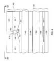
- FIG. 4is an ABS view, taken from line 4 - 4 of FIG. 3 and rotated 180 degrees, of a magnetic head according to an embodiment of the present invention
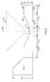
- FIGS. 5-7are top down views of a trailing magnetic shield illustrating a challenge presented by the use of such trailing magnetic shields
- FIG. 8is a top down view of a trailing shield illustrating an embodiment of the present invention.
- FIG. 9is a top down vie of a trailing shield illustrating another embodiment of the invention.
- FIG. 1there is shown a disk drive 100 embodying this invention.
- at least one rotatable magnetic disk 112is supported on a spindle 114 and rotated by a disk drive motor 118 .
- the magnetic recording on each diskis in the form of annular patterns of concentric data tracks (not shown) on the magnetic disk 112 .
- At least one slider 113is positioned near the magnetic disk 112 , each slider 113 supporting one or more magnetic head assemblies 221 . As the magnetic disk rotates, slider 113 moves radially in and out over the disk surface 122 so that the magnetic head assembly 121 may access different tracks of the magnetic disk where desired data are written.
- Each slider 113is attached to an actuator arm 119 by way of a suspension 115 .
- the suspension 115provides a slight spring force which biases slider 113 against the disk surface 122 .
- Each actuator arm 119is attached to an actuator means 127 .
- the actuator means 127 as shown in FIG. 1may be a voice coil motor (VCM).
- the VCMcomprises a coil movable within a fixed magnetic field, the direction and speed of the coil movements being controlled by the motor current signals supplied by controller 129 .
- the rotation of the magnetic disk 112generates an air bearing between the slider 113 and the disk surface 122 which exerts an upward force or lift on the slider.
- the air bearingthus counter-balances the slight spring force of suspension 115 and supports slider 113 off and slightly above the disk surface by a small, substantially constant spacing during normal operation.
- control unit 129The various components of the disk storage system are controlled in operation by control signals generated by control unit 129 , such as access control signals and internal clock signals.
- control unit 129comprises logic control circuits, storage means and a microprocessor.
- the control unit 129generates control signals to control various system operations such as drive motor control signals on line 123 and head position and seek control signals on line 128 .
- the control signals on line 128provide the desired current profiles to optimally move and position slider 113 to the desired data track on disk 112 .
- Write and read signalsare communicated to and from write and read heads 121 by way of recording channel 125 .
- FIG. 2is an ABS view of the slider 113 , and as can be seen the magnetic head including an inductive write head and a read sensor, is located at a trailing edge of the slider.
- the magnetic head including an inductive write head and a read sensoris located at a trailing edge of the slider.
- FIG. 1The above description of a typical magnetic disk storage system, and the accompanying illustration of FIG. 1 are for representation purposes only. It should be apparent that disk storage systems may contain a large number of disks and actuators, and each actuator may support a number of sliders.
- the magnetic head 221for use in a perpendicular magnetic recording system is described.
- the head 221includes a write element 302 and a read sensor 304 .
- the read sensoris preferably a giant magnetoresistive (GMR) sensor and is preferably a current perpendicular to plane (CPP) GMR sensor.
- CPP GMR sensorsare particularly well suited for use in perpendicular recording systems.
- the sensor 304could be another type of sensor such as a current in plane (CIP) GMR sensor or, a tunnel junction sensor (TMR) or some other type of sensor.
- the sensor 304is located between and insulated from first and second magnetic shields 306 , 308 and embedded in a dielectric material 307 .
- the magnetic shieldswhich can be constructed of for example CoFe or NiFe, absorb magnetic fields, such as those from up-track or down-track data signals, ensuring that the read sensor 304 only detects the desired data track located between the shields 306 , 308 .
- a non-magnetic, electrically insulating gap layer 309may be provided between the shield 308 and the write head 302 .
- the write element 302includes a write pole 310 that is magnetically connected with a magnetic shaping layer 312 , and is embedded within an insulation material 311 .
- the write polehas a small cross section at the air bearing surface and is constructed of a material having a high saturation moment, such as NiFe or CoFe.
- the return pole layer 314is constructed of a magnetic material such as CoFe or NiFe and has a cross section parallel to the ABS surface that is significantly larger than that of the write pole 310 as shown in FIG. 4 .
- the return pole 314is magnetically connected with the shaping layer 312 by a back gap portion 316 as shown in FIG. 3 .
- the return pole 314 and back gap 316can be constructed of, for example, NiFe, CoFe or some other magnetic material.
- An electrically conductive write coil 317passes through the write element 302 between the shaping layer 312 , and the return pole 314 .
- the write coil 317is surrounded by an electrically insulating material 320 that electrically insulates the turns of the coil 317 from one another and electrically isolates the coil 317 from the surrounding magnetic structures 310 , 312 , 316 , 314 .
- the resulting magnetic fieldcauses a magnetic flux to flow through the return pole 314 , back gap 316 , shaping layer 312 and write pole 310 .
- This magnetic fluxcauses a write field 321 to be emitted toward an adjacent magnetic medium.
- the shaping layer 312is also surrounded by an insulation layer 321 which separates the shaping layer 312 from the ABS.
- the insulation layers 320 , 321 , 311can all be constructed of the same material, such as alumina (Al 2 0 3 ) or of different electrically insulating materials.
- the write head element 302also includes a trailing shield 322 .
- the write pole 310has a trailing edge 402 and a leading edge 404 .
- the terms trailing and leadingare with respect to the direction of travel along a data track when the write head 302 is in use.
- the write pole 310also preferably has first and second laterally opposing sides 406 , 408 that are configured to define a width at the leading edge 404 that is narrower than the width at the trailing edge 404 , forming a write pole 310 having a trapezoidal shape.
- This trapezoidal shapeis useful in preventing adjacent track writing due to skew of the write head 302 when the head 302 is located at extreme outer or inner positions over the disk. However, this trapezoidal shape of the write head 310 is not necessary to practice the present invention.
- the magnetic trailing shield 322is separated from the write pole 310 , by a trailing gap 412 , which is filled with a non-magnetic material such as Rh or alumina.
- the trailing shield gapis constructed of a thickness to provide a desired amount of write field canting, while not causing too much field to leak to the shield 322 which would result in a loss of write field performance.
- the trailing shield 322can be constructed of a magnetic material such as NiFe.
- FIG. 5a top-down view of a trailing shield illustrates a challenge presented by the use of a trailing shield 502 in a perpendicular magnetic recording system.
- a trailing shieldis shown having an ABS edge 504 and a back edge 506 measured in a throat height direction.
- the trailing shield 502has a narrower throat height 508 at its center and flares to a wider throat height 510 at the outer ends.
- the write pole 310is shown in a dashed line in FIG. 5 and is located beneath the trailing shield 502 in the view shown in FIG. 5 .
- Magnetic flux 512 from the pole tip of the write pole 310travels from the center, where the write pole is located, to the outer ends, where this flux can be absorbed by the shield.
- Other stray magnetic fields 514can be emitted from the flare region 516 of the write pole and even from the underlying shaping layer 312 or coil 317 (not shown in FIG. 5 ).
- stray fieldscan combine with the magnetic flux 312 to cause magnetic saturation which, in turn, causes a magnetic field 518 to be emitted from the ABS edge 504 of the shield 502 .
- a flux concentration pointsuch as the point where the narrow constant flare region 508 meets a flared region 520 can cause a spike 522 in this emitted field.
- This spike 522is, of course, undesirable as it may cause Wide Area Track Erasure (WATER) as discussed earlier.
- WATERWide Area Track Erasure
- a trailing shield 802is shown constructed over a write pole 310 , which is beneath the shield 802 , into the plane of the page in FIG. 8 .
- the shield 802is constructed of a magnetic material, such as, but not limited to NiFe.
- the shield 802is preferably generally symmetrical about a centerline 804 , although certain variations and asymmetry are possible.
- the shield 800has an ABS edge 802 and a back edge 808 opposite the ABS edge 806 .
- the shieldhas a center, shallow, constant throat height section 810 , a flared tapered intermediate region 812 , and a deep constant throat height outer section 814 .
- the term “throat height”refers to the distance from the ABS 806 to the back edge 808 of the shield 800 .
- the term “lateral”will be defined herein to refer to a distance from the centerline 804 (ie. to the right and left as shown in FIG. 8 ).
- the term forwardwill refer to a direction toward or beyond the ABS (ie. toward the bottom of the page in FIG. 8 ).
- the term “back”will refer to the direction away from the ABS (ie. the throat height direction or toward the top of the page as shown in FIG. 8 ).
- the deep constant throat height sections 814are formed at laterally outward positions of the trailing shield 802 , and each of the tapered sections 812 are located at laterally intermediate positions between the outer, constant throat height section 814 and the center, shallow, constant throat height section 810 .
- the deeper constant throat height section 814preferably has a throat height TH 1 that is 1.5 to 5 times the throat height TH 2 of the shallow, constant throat height center section 810 .
- the shallow, constant throat height sectionpreferably extends a distance of 0.4-0.5 um from the centerline.
- the back edge 808 of the tapered portions 812preferably forms an angle of 10 to 20 degrees or about 15 degrees with respect to the ABS 806 .
- the choking provided by the tapered portionprevents excessive flux from entering the TS center portion, such as from stray fields that might be picked up by the larger outer portions 814 .
- the gradual tapering of the throat heightalso avoids saturation as well as preventing excessive charge.
- the outer constant throat height portions 814provide sufficient shield area to absorb desired flux from the center portion 810 , while having a sufficiently limited area so as to prevent the outer portions from excessively picking up stray magnetic fields.
- a shield 900can be configured with an anchor pad 902 .
- the anchor pad 902can extend from an end of the shield 900 . There, may be an anchor pad on one end or on both ends of the shield 900 .
- the anchor pad 902can extend a distance 904 of, for example, 5 um from the end of the outer constant throat height section 814 .
- the anchor pad portion 902may extend significantly further in the throat height direction than the rest of the shield 900 , having a throat height Th 3 that is larger than TH 1 or TH 2 .
- the anchor padprovides the shield with mechanical stiffness and prevents the shield 902 from moving from its desired position.
Landscapes
- Engineering & Computer Science (AREA)
- Manufacturing & Machinery (AREA)
- Physics & Mathematics (AREA)
- Electromagnetism (AREA)
- Magnetic Heads (AREA)
Abstract
Description
Claims (20)
Priority Applications (7)
| Application Number | Priority Date | Filing Date | Title |
|---|---|---|---|
| US11/412,017US7538976B2 (en) | 2006-04-25 | 2006-04-25 | Trailing shield design for reducing wide area track erasure (water) in a perpendicular recording system |
| EP07250690AEP1852856A3 (en) | 2006-04-25 | 2007-02-20 | Trailing shield design for reducing wide area track erasure (water) in a perpendicular recording system |
| TW096108118ATW200809803A (en) | 2006-04-25 | 2007-03-09 | Trailing shield design for reducing wide area track erasure(water) in a perpendicular recording system |
| KR1020070034157AKR20070105241A (en) | 2006-04-25 | 2007-04-06 | Trailing shield design to reduce wide-angle track erase in vertical recording systems |
| SG200702709-7ASG136899A1 (en) | 2006-04-25 | 2007-04-12 | Trailing shield design for reducing wide area track erasure (water) in a perpendicular recording system |
| JP2007112635AJP2007294095A (en) | 2006-04-25 | 2007-04-23 | Magnetic shield and magnetic write head |
| CNA2007101018638ACN101064110A (en) | 2006-04-25 | 2007-04-25 | Trailing shield design for reducing wide area track erasure(water) in a perpendicular recording system |
Applications Claiming Priority (1)
| Application Number | Priority Date | Filing Date | Title |
|---|---|---|---|
| US11/412,017US7538976B2 (en) | 2006-04-25 | 2006-04-25 | Trailing shield design for reducing wide area track erasure (water) in a perpendicular recording system |
Publications (2)
| Publication Number | Publication Date |
|---|---|
| US20070247751A1 US20070247751A1 (en) | 2007-10-25 |
| US7538976B2true US7538976B2 (en) | 2009-05-26 |
Family
ID=38229563
Family Applications (1)
| Application Number | Title | Priority Date | Filing Date |
|---|---|---|---|
| US11/412,017Expired - Fee RelatedUS7538976B2 (en) | 2006-04-25 | 2006-04-25 | Trailing shield design for reducing wide area track erasure (water) in a perpendicular recording system |
Country Status (7)
| Country | Link |
|---|---|
| US (1) | US7538976B2 (en) |
| EP (1) | EP1852856A3 (en) |
| JP (1) | JP2007294095A (en) |
| KR (1) | KR20070105241A (en) |
| CN (1) | CN101064110A (en) |
| SG (1) | SG136899A1 (en) |
| TW (1) | TW200809803A (en) |
Cited By (5)
| Publication number | Priority date | Publication date | Assignee | Title |
|---|---|---|---|---|
| US20110063755A1 (en)* | 2009-09-17 | 2011-03-17 | Headway Technologies, Inc. | PMR write with flux choking area |
| US8385020B2 (en) | 2010-11-24 | 2013-02-26 | Headway Technologies, Inc. | Modified shield design to eliminate the far-field WATE problem |
| US9443541B1 (en) | 2015-03-24 | 2016-09-13 | Western Digital (Fremont), Llc | Magnetic writer having a gradient in saturation magnetization of the shields and return pole |
| US9779765B1 (en) | 2016-08-24 | 2017-10-03 | Western Digital (Fremont), Llc | Perpendicular magnetic recording writer having improved performance and wide area track erasure reliability |
| US20250078864A1 (en)* | 2023-09-06 | 2025-03-06 | Western Digital Technologies, Inc. | DFL TDMR Middle Shield Throat Height Control for Improved Stability |
Families Citing this family (5)
| Publication number | Priority date | Publication date | Assignee | Title |
|---|---|---|---|---|
| US20090262464A1 (en)* | 2008-04-21 | 2009-10-22 | Hardayal Singh Gill | Perpendicular magnetic write head having a wrap around shield constructed of a low permeability material for reduced adjacent track erasure |
| JP2009283067A (en)* | 2008-05-22 | 2009-12-03 | Hitachi Global Storage Technologies Netherlands Bv | Magnetic head for perpendicular recording and magnetic recording apparatus |
| US9232306B2 (en) | 2012-06-10 | 2016-01-05 | Apple Inc. | Systems and methods for reducing stray magnetic flux |
| US11657837B2 (en)* | 2021-05-19 | 2023-05-23 | Western Digital Technologies, Inc. | Magnetic recording head with trailing shield having multiple throat-heights |
| US11682417B1 (en)* | 2022-05-09 | 2023-06-20 | Western Digital Technologies, Inc. | Asymmetric write head shields compatible with dual-free-layer (DFL) readers |
Citations (22)
| Publication number | Priority date | Publication date | Assignee | Title |
|---|---|---|---|---|
| US4317148A (en) | 1980-01-24 | 1982-02-23 | Sperry Corporation | Transducer for perpendicular magnetic recording |
| US4656546A (en) | 1985-01-22 | 1987-04-07 | Digital Equipment Corporation | Vertical magnetic recording arrangement |
| US5075280A (en) | 1988-11-01 | 1991-12-24 | Ampex Corporation | Thin film magnetic head with improved flux concentration for high density recording/playback utilizing superconductors |
| US6469876B1 (en) | 1999-10-12 | 2002-10-22 | Tdk Corporation | Thin-film magnetic head and method of manufacturing same |
| US20040021981A1 (en) | 2000-09-11 | 2004-02-05 | Sumihito Morita | Thin film magnetic head having partial insulating layer formed on bottom pole layer through gap layer and method of manufacturing the same |
| US20050068671A1 (en) | 2003-09-29 | 2005-03-31 | Yimin Hsu | Magnetic transducer for perpendicular magnetic recording with single pole write head with trailing shield |
| US20050068678A1 (en)* | 2003-09-30 | 2005-03-31 | Yimin Hsu | Head for perpendicular magnetic recording with a shield structure connected to the return pole piece |
| US20050083605A1 (en) | 2003-10-17 | 2005-04-21 | Headway Technologies, Inc. | Fully shielded perpendicular recording writer |
| US20050141137A1 (en)* | 2003-12-24 | 2005-06-30 | Hitachi Global Storage Technologies Netherlands, B.V. | Magnetic recording head for perpendicular recording, fabrication process, and magnetic disk storage apparatus mounting the magnetic head |
| US20050180048A1 (en) | 2004-02-13 | 2005-08-18 | Hitachi Global Technologies Netherlands B.V. | Perpendicular magnetic recording head built using an air-bearing surface damascene process |
| US20050190479A1 (en)* | 2004-02-27 | 2005-09-01 | Terris Bruce D. | Thermally-assisted perpendicular magnetic recording system and head |
| US20050219746A1 (en) | 2004-03-31 | 2005-10-06 | Headway Technologies, Inc. | Stitched shielded pole structure for a perpendicular magnetic recording write head |
| US20060000794A1 (en)* | 2004-06-30 | 2006-01-05 | Quang Le | Methods of fabricating magnetic write heads with side and trailing shield structures |
| US20070121248A1 (en)* | 2005-11-30 | 2007-05-31 | Headway Technologies, Inc. | Magnetic head for perpendicular magnetic recording and method of manufacturing same |
| US20070146931A1 (en)* | 2005-12-22 | 2007-06-28 | Hitachi Global Storage Technologies | Method for fabricating a side shield for a flux guide layer for perpendicular magnetic recording |
| US20070211377A1 (en)* | 2006-03-10 | 2007-09-13 | Headway Technologies, Inc. | Magnetic head for perpendicular magnetic recording and method of manufacturing same |
| US20070230045A1 (en)* | 2006-03-28 | 2007-10-04 | Hitachi Global Storage Technologies | Two step corner recess for secondary stray field reduction in a perpendicular magnetic recording head |
| US20070236831A1 (en)* | 2006-04-06 | 2007-10-11 | Hitachi Global Storage Technologies Netherlands B.V. | Shaped trailing shield of a perpendicular recording write element |
| US20070245545A1 (en)* | 2006-04-25 | 2007-10-25 | Hitachi Global Storage Technologies | Method of manufacturing a wrap around shield for a perpendicular write pole using a laminated mask |
| US20070247749A1 (en)* | 2006-04-25 | 2007-10-25 | Bonhote Christian R | Structure and method for reduced corrosion of auxiliary poles during the fabrication of perpendicular write heads |
| US20070258167A1 (en)* | 2006-04-25 | 2007-11-08 | Hitachi Global Storage Technologies | Perpendicular magnetic write head having a magnetic write pole with a concave trailing edge |
| US20080002291A1 (en)* | 2006-04-25 | 2008-01-03 | Hitachi Global Storage Technologies | Plated perpendicular magnetic recording main pole process and enhancements |
- 2006
- 2006-04-25USUS11/412,017patent/US7538976B2/ennot_activeExpired - Fee Related
- 2007
- 2007-02-20EPEP07250690Apatent/EP1852856A3/ennot_activeWithdrawn
- 2007-03-09TWTW096108118Apatent/TW200809803A/enunknown
- 2007-04-06KRKR1020070034157Apatent/KR20070105241A/ennot_activeWithdrawn
- 2007-04-12SGSG200702709-7Apatent/SG136899A1/enunknown
- 2007-04-23JPJP2007112635Apatent/JP2007294095A/enactivePending
- 2007-04-25CNCNA2007101018638Apatent/CN101064110A/enactivePending
Patent Citations (23)
| Publication number | Priority date | Publication date | Assignee | Title |
|---|---|---|---|---|
| US4317148A (en) | 1980-01-24 | 1982-02-23 | Sperry Corporation | Transducer for perpendicular magnetic recording |
| US4656546A (en) | 1985-01-22 | 1987-04-07 | Digital Equipment Corporation | Vertical magnetic recording arrangement |
| US5075280A (en) | 1988-11-01 | 1991-12-24 | Ampex Corporation | Thin film magnetic head with improved flux concentration for high density recording/playback utilizing superconductors |
| US6469876B1 (en) | 1999-10-12 | 2002-10-22 | Tdk Corporation | Thin-film magnetic head and method of manufacturing same |
| US20040021981A1 (en) | 2000-09-11 | 2004-02-05 | Sumihito Morita | Thin film magnetic head having partial insulating layer formed on bottom pole layer through gap layer and method of manufacturing the same |
| US20050068671A1 (en) | 2003-09-29 | 2005-03-31 | Yimin Hsu | Magnetic transducer for perpendicular magnetic recording with single pole write head with trailing shield |
| US20050068678A1 (en)* | 2003-09-30 | 2005-03-31 | Yimin Hsu | Head for perpendicular magnetic recording with a shield structure connected to the return pole piece |
| EP1522991A1 (en) | 2003-09-30 | 2005-04-13 | Hitachi Global Storage Technologies B. V. | Thin film magnetic recording head |
| US20050083605A1 (en) | 2003-10-17 | 2005-04-21 | Headway Technologies, Inc. | Fully shielded perpendicular recording writer |
| US20050141137A1 (en)* | 2003-12-24 | 2005-06-30 | Hitachi Global Storage Technologies Netherlands, B.V. | Magnetic recording head for perpendicular recording, fabrication process, and magnetic disk storage apparatus mounting the magnetic head |
| US20050180048A1 (en) | 2004-02-13 | 2005-08-18 | Hitachi Global Technologies Netherlands B.V. | Perpendicular magnetic recording head built using an air-bearing surface damascene process |
| US20050190479A1 (en)* | 2004-02-27 | 2005-09-01 | Terris Bruce D. | Thermally-assisted perpendicular magnetic recording system and head |
| US20050219746A1 (en) | 2004-03-31 | 2005-10-06 | Headway Technologies, Inc. | Stitched shielded pole structure for a perpendicular magnetic recording write head |
| US20060000794A1 (en)* | 2004-06-30 | 2006-01-05 | Quang Le | Methods of fabricating magnetic write heads with side and trailing shield structures |
| US20070121248A1 (en)* | 2005-11-30 | 2007-05-31 | Headway Technologies, Inc. | Magnetic head for perpendicular magnetic recording and method of manufacturing same |
| US20070146931A1 (en)* | 2005-12-22 | 2007-06-28 | Hitachi Global Storage Technologies | Method for fabricating a side shield for a flux guide layer for perpendicular magnetic recording |
| US20070211377A1 (en)* | 2006-03-10 | 2007-09-13 | Headway Technologies, Inc. | Magnetic head for perpendicular magnetic recording and method of manufacturing same |
| US20070230045A1 (en)* | 2006-03-28 | 2007-10-04 | Hitachi Global Storage Technologies | Two step corner recess for secondary stray field reduction in a perpendicular magnetic recording head |
| US20070236831A1 (en)* | 2006-04-06 | 2007-10-11 | Hitachi Global Storage Technologies Netherlands B.V. | Shaped trailing shield of a perpendicular recording write element |
| US20070245545A1 (en)* | 2006-04-25 | 2007-10-25 | Hitachi Global Storage Technologies | Method of manufacturing a wrap around shield for a perpendicular write pole using a laminated mask |
| US20070247749A1 (en)* | 2006-04-25 | 2007-10-25 | Bonhote Christian R | Structure and method for reduced corrosion of auxiliary poles during the fabrication of perpendicular write heads |
| US20070258167A1 (en)* | 2006-04-25 | 2007-11-08 | Hitachi Global Storage Technologies | Perpendicular magnetic write head having a magnetic write pole with a concave trailing edge |
| US20080002291A1 (en)* | 2006-04-25 | 2008-01-03 | Hitachi Global Storage Technologies | Plated perpendicular magnetic recording main pole process and enhancements |
Non-Patent Citations (1)
| Title |
|---|
| European Search Report from application No. 07250690 mailed on Jun. 5, 2008. |
Cited By (7)
| Publication number | Priority date | Publication date | Assignee | Title |
|---|---|---|---|---|
| US20110063755A1 (en)* | 2009-09-17 | 2011-03-17 | Headway Technologies, Inc. | PMR write with flux choking area |
| US8085498B2 (en) | 2009-09-17 | 2011-12-27 | Headway Technologies, Inc. | PMR write with flux choking area |
| US8385020B2 (en) | 2010-11-24 | 2013-02-26 | Headway Technologies, Inc. | Modified shield design to eliminate the far-field WATE problem |
| US9443541B1 (en) | 2015-03-24 | 2016-09-13 | Western Digital (Fremont), Llc | Magnetic writer having a gradient in saturation magnetization of the shields and return pole |
| US9779765B1 (en) | 2016-08-24 | 2017-10-03 | Western Digital (Fremont), Llc | Perpendicular magnetic recording writer having improved performance and wide area track erasure reliability |
| US20250078864A1 (en)* | 2023-09-06 | 2025-03-06 | Western Digital Technologies, Inc. | DFL TDMR Middle Shield Throat Height Control for Improved Stability |
| US12437780B2 (en)* | 2023-09-06 | 2025-10-07 | Western Digital Technologies, Inc. | DFL TDMR middle shield throat height control for improved stability |
Also Published As
| Publication number | Publication date |
|---|---|
| JP2007294095A (en) | 2007-11-08 |
| US20070247751A1 (en) | 2007-10-25 |
| SG136899A1 (en) | 2007-11-29 |
| CN101064110A (en) | 2007-10-31 |
| KR20070105241A (en) | 2007-10-30 |
| EP1852856A2 (en) | 2007-11-07 |
| TW200809803A (en) | 2008-02-16 |
| EP1852856A3 (en) | 2008-07-09 |
Similar Documents
| Publication | Publication Date | Title |
|---|---|---|
| TWI417876B (en) | Magnetic write head, magnetic head, and magnetic data recording system | |
| US7894159B2 (en) | Perpendicular write head with independent trailing shield designs | |
| US8120874B2 (en) | Perpendicular write head having a modified wrap-around shield to improve overwrite, adjacent track interference and magnetic core width dependence on skew angle | |
| US8111479B2 (en) | Perpendicular magnetic recording head having a notched trailing shield | |
| US7969684B2 (en) | Write head design and method for reducing adjacent track interference at very narrow track widths | |
| US7881019B2 (en) | Two step corner recess for secondary stray field reduction in a perpendicular magnetic recording head | |
| US7538976B2 (en) | Trailing shield design for reducing wide area track erasure (water) in a perpendicular recording system | |
| US20070268625A1 (en) | Method for manufacturing a magnetic write head having a trailing shield with an accurately controlled trailing shield gap thickness | |
| US20090262464A1 (en) | Perpendicular magnetic write head having a wrap around shield constructed of a low permeability material for reduced adjacent track erasure | |
| US7551396B2 (en) | Perpendicular magnetic write head having a studded trailing shield compatible with read/write offset | |
| US7508628B2 (en) | Winged pole and shield structure for reducing stray field in a perpendicular write head | |
| US7280314B2 (en) | Lower saturation field structure for perpendicular AFC pole | |
| US7764469B2 (en) | Notched shield and pole structure with slanted wing for perpendicular recording | |
| US20080112088A1 (en) | Perpendicular magnetic write head having a wrap around trailing shield with a flux return path | |
| US7768741B2 (en) | Magnetic write head design for reducing wide area track erasure | |
| EP1653450B1 (en) | Double notched shield and pole structure for stray field reduction in a magnetic head | |
| US7990652B2 (en) | Perpendicular magnetic write head with stepped write pole for reduced MCW dependency on skew angle | |
| US8068311B2 (en) | Perpendicular magnetic write head having a novel trailing return pole for reduced wide-area-track-erasure |
Legal Events
| Date | Code | Title | Description |
|---|---|---|---|
| AS | Assignment | Owner name:HITACHI GLOBAL STORAGE TECHNOLOGIES NETHERLANDS B. Free format text:ASSIGNMENT OF ASSIGNORS INTEREST;ASSIGNORS:HSIAO, WEN-CHIEN DAVID;HSU, YIMIN;NIKITIN, VLADIMIR;REEL/FRAME:017767/0279;SIGNING DATES FROM 20060404 TO 20060424 | |
| FEPP | Fee payment procedure | Free format text:PAYOR NUMBER ASSIGNED (ORIGINAL EVENT CODE: ASPN); ENTITY STATUS OF PATENT OWNER: LARGE ENTITY | |
| FPAY | Fee payment | Year of fee payment:4 | |
| AS | Assignment | Owner name:HGST, NETHERLANDS B.V., NETHERLANDS Free format text:CHANGE OF NAME;ASSIGNOR:HGST, NETHERLANDS B.V.;REEL/FRAME:029341/0777 Effective date:20120723 Owner name:HGST NETHERLANDS B.V., NETHERLANDS Free format text:CHANGE OF NAME;ASSIGNOR:HITACHI GLOBAL STORAGE TECHNOLOGIES NETHERLANDS B.V.;REEL/FRAME:029341/0777 Effective date:20120723 | |
| AS | Assignment | Owner name:WESTERN DIGITAL TECHNOLOGIES, INC., CALIFORNIA Free format text:ASSIGNMENT OF ASSIGNORS INTEREST;ASSIGNOR:HGST NETHERLANDS B.V.;REEL/FRAME:040821/0550 Effective date:20160831 | |
| REMI | Maintenance fee reminder mailed | ||
| LAPS | Lapse for failure to pay maintenance fees | ||
| STCH | Information on status: patent discontinuation | Free format text:PATENT EXPIRED DUE TO NONPAYMENT OF MAINTENANCE FEES UNDER 37 CFR 1.362 | |
| FP | Lapsed due to failure to pay maintenance fee | Effective date:20170526 |