US7538326B2 - Visible light and IR combined image camera with a laser pointer - Google Patents
Visible light and IR combined image camera with a laser pointerDownload PDFInfo
- Publication number
- US7538326B2 US7538326B2US11/294,752US29475205AUS7538326B2US 7538326 B2US7538326 B2US 7538326B2US 29475205 AUS29475205 AUS 29475205AUS 7538326 B2US7538326 B2US 7538326B2
- Authority
- US
- United States
- Prior art keywords
- camera module
- camera
- image
- infrared
- visible
- Prior art date
- Legal status (The legal status is an assumption and is not a legal conclusion. Google has not performed a legal analysis and makes no representation as to the accuracy of the status listed.)
- Active
Links
- 238000000034methodMethods0.000claimsabstractdescription47
- 230000005355Hall effectEffects0.000claimsdescription13
- 230000007246mechanismEffects0.000claimsdescription10
- 230000003287optical effectEffects0.000description12
- 238000002156mixingMethods0.000description9
- 230000006870functionEffects0.000description7
- 238000003491arrayMethods0.000description6
- 239000003086colorantSubstances0.000description6
- 238000010586diagramMethods0.000description6
- 239000003550markerSubstances0.000description5
- 230000008569processEffects0.000description5
- 238000009529body temperature measurementMethods0.000description4
- 238000012937correctionMethods0.000description4
- 239000000203mixtureSubstances0.000description4
- 230000005855radiationEffects0.000description3
- 238000001931thermographyMethods0.000description3
- 230000000007visual effectEffects0.000description3
- 230000007547defectEffects0.000description2
- 238000009795derivationMethods0.000description2
- 238000012546transferMethods0.000description2
- 238000001429visible spectrumMethods0.000description2
- 230000001413cellular effectEffects0.000description1
- 238000013461designMethods0.000description1
- 238000001514detection methodMethods0.000description1
- 238000003384imaging methodMethods0.000description1
- 238000007689inspectionMethods0.000description1
- 238000012544monitoring processMethods0.000description1
- 238000012545processingMethods0.000description1
- 230000008439repair processEffects0.000description1
- 238000001228spectrumMethods0.000description1
- 238000012360testing methodMethods0.000description1
Images


Classifications
- G—PHYSICS
- G01—MEASURING; TESTING
- G01C—MEASURING DISTANCES, LEVELS OR BEARINGS; SURVEYING; NAVIGATION; GYROSCOPIC INSTRUMENTS; PHOTOGRAMMETRY OR VIDEOGRAMMETRY
- G01C3/00—Measuring distances in line of sight; Optical rangefinders
- G01C3/02—Details
- G01C3/06—Use of electric means to obtain final indication
- G01C3/08—Use of electric radiation detectors
- G—PHYSICS
- G01—MEASURING; TESTING
- G01J—MEASUREMENT OF INTENSITY, VELOCITY, SPECTRAL CONTENT, POLARISATION, PHASE OR PULSE CHARACTERISTICS OF INFRARED, VISIBLE OR ULTRAVIOLET LIGHT; COLORIMETRY; RADIATION PYROMETRY
- G01J5/00—Radiation pyrometry, e.g. infrared or optical thermometry
- G01J5/02—Constructional details
- G01J5/025—Interfacing a pyrometer to an external device or network; User interface
- G—PHYSICS
- G01—MEASURING; TESTING
- G01J—MEASUREMENT OF INTENSITY, VELOCITY, SPECTRAL CONTENT, POLARISATION, PHASE OR PULSE CHARACTERISTICS OF INFRARED, VISIBLE OR ULTRAVIOLET LIGHT; COLORIMETRY; RADIATION PYROMETRY
- G01J5/00—Radiation pyrometry, e.g. infrared or optical thermometry
- G01J5/02—Constructional details
- G01J5/0265—Handheld, portable
- G—PHYSICS
- G01—MEASURING; TESTING
- G01J—MEASUREMENT OF INTENSITY, VELOCITY, SPECTRAL CONTENT, POLARISATION, PHASE OR PULSE CHARACTERISTICS OF INFRARED, VISIBLE OR ULTRAVIOLET LIGHT; COLORIMETRY; RADIATION PYROMETRY
- G01J5/00—Radiation pyrometry, e.g. infrared or optical thermometry
- G01J5/02—Constructional details
- G01J5/0295—Nulling devices or absolute detection
- G—PHYSICS
- G01—MEASURING; TESTING
- G01J—MEASUREMENT OF INTENSITY, VELOCITY, SPECTRAL CONTENT, POLARISATION, PHASE OR PULSE CHARACTERISTICS OF INFRARED, VISIBLE OR ULTRAVIOLET LIGHT; COLORIMETRY; RADIATION PYROMETRY
- G01J5/00—Radiation pyrometry, e.g. infrared or optical thermometry
- G01J5/02—Constructional details
- G01J5/07—Arrangements for adjusting the solid angle of collected radiation, e.g. adjusting or orienting field of view, tracking position or encoding angular position
- G—PHYSICS
- G01—MEASURING; TESTING
- G01J—MEASUREMENT OF INTENSITY, VELOCITY, SPECTRAL CONTENT, POLARISATION, PHASE OR PULSE CHARACTERISTICS OF INFRARED, VISIBLE OR ULTRAVIOLET LIGHT; COLORIMETRY; RADIATION PYROMETRY
- G01J5/00—Radiation pyrometry, e.g. infrared or optical thermometry
- G01J5/02—Constructional details
- G01J5/08—Optical arrangements
- G01J5/0859—Sighting arrangements, e.g. cameras
- G—PHYSICS
- G01—MEASURING; TESTING
- G01J—MEASUREMENT OF INTENSITY, VELOCITY, SPECTRAL CONTENT, POLARISATION, PHASE OR PULSE CHARACTERISTICS OF INFRARED, VISIBLE OR ULTRAVIOLET LIGHT; COLORIMETRY; RADIATION PYROMETRY
- G01J5/00—Radiation pyrometry, e.g. infrared or optical thermometry
- G01J5/02—Constructional details
- G01J5/08—Optical arrangements
- G01J5/0896—Optical arrangements using a light source, e.g. for illuminating a surface
- H—ELECTRICITY
- H04—ELECTRIC COMMUNICATION TECHNIQUE
- H04N—PICTORIAL COMMUNICATION, e.g. TELEVISION
- H04N23/00—Cameras or camera modules comprising electronic image sensors; Control thereof
- H04N23/10—Cameras or camera modules comprising electronic image sensors; Control thereof for generating image signals from different wavelengths
- H04N23/11—Cameras or camera modules comprising electronic image sensors; Control thereof for generating image signals from different wavelengths for generating image signals from visible and infrared light wavelengths
- H—ELECTRICITY
- H04—ELECTRIC COMMUNICATION TECHNIQUE
- H04N—PICTORIAL COMMUNICATION, e.g. TELEVISION
- H04N23/00—Cameras or camera modules comprising electronic image sensors; Control thereof
- H04N23/20—Cameras or camera modules comprising electronic image sensors; Control thereof for generating image signals from infrared radiation only
- H—ELECTRICITY
- H04—ELECTRIC COMMUNICATION TECHNIQUE
- H04N—PICTORIAL COMMUNICATION, e.g. TELEVISION
- H04N23/00—Cameras or camera modules comprising electronic image sensors; Control thereof
- H04N23/45—Cameras or camera modules comprising electronic image sensors; Control thereof for generating image signals from two or more image sensors being of different type or operating in different modes, e.g. with a CMOS sensor for moving images in combination with a charge-coupled device [CCD] for still images
- H—ELECTRICITY
- H04—ELECTRIC COMMUNICATION TECHNIQUE
- H04N—PICTORIAL COMMUNICATION, e.g. TELEVISION
- H04N23/00—Cameras or camera modules comprising electronic image sensors; Control thereof
- H04N23/60—Control of cameras or camera modules
- H04N23/63—Control of cameras or camera modules by using electronic viewfinders
- H04N23/633—Control of cameras or camera modules by using electronic viewfinders for displaying additional information relating to control or operation of the camera
- H04N23/635—Region indicators; Field of view indicators
- H—ELECTRICITY
- H04—ELECTRIC COMMUNICATION TECHNIQUE
- H04N—PICTORIAL COMMUNICATION, e.g. TELEVISION
- H04N23/00—Cameras or camera modules comprising electronic image sensors; Control thereof
- H04N23/60—Control of cameras or camera modules
- H04N23/67—Focus control based on electronic image sensor signals
- H—ELECTRICITY
- H10—SEMICONDUCTOR DEVICES; ELECTRIC SOLID-STATE DEVICES NOT OTHERWISE PROVIDED FOR
- H10F—INORGANIC SEMICONDUCTOR DEVICES SENSITIVE TO INFRARED RADIATION, LIGHT, ELECTROMAGNETIC RADIATION OF SHORTER WAVELENGTH OR CORPUSCULAR RADIATION
- H10F39/00—Integrated devices, or assemblies of multiple devices, comprising at least one element covered by group H10F30/00, e.g. radiation detectors comprising photodiode arrays
- H10F39/80—Constructional details of image sensors
- H10F39/804—Containers or encapsulations
- H—ELECTRICITY
- H10—SEMICONDUCTOR DEVICES; ELECTRIC SOLID-STATE DEVICES NOT OTHERWISE PROVIDED FOR
- H10F—INORGANIC SEMICONDUCTOR DEVICES SENSITIVE TO INFRARED RADIATION, LIGHT, ELECTROMAGNETIC RADIATION OF SHORTER WAVELENGTH OR CORPUSCULAR RADIATION
- H10F39/00—Integrated devices, or assemblies of multiple devices, comprising at least one element covered by group H10F30/00, e.g. radiation detectors comprising photodiode arrays
- H10F39/80—Constructional details of image sensors
- H10F39/806—Optical elements or arrangements associated with the image sensors
- H—ELECTRICITY
- H01—ELECTRIC ELEMENTS
- H01L—SEMICONDUCTOR DEVICES NOT COVERED BY CLASS H10
- H01L2924/00—Indexing scheme for arrangements or methods for connecting or disconnecting semiconductor or solid-state bodies as covered by H01L24/00
- H01L2924/0001—Technical content checked by a classifier
- H01L2924/0002—Not covered by any one of groups H01L24/00, H01L24/00 and H01L2224/00
Definitions
- IR imagean image of a scene using only energy in the far-infrared portion of the electromagnetic spectrum, typically in the 8-14 micron range. Images obtained using these cameras assign colors or gray-levels to the pixels composing the scene based on the intensity of the IR radiation reaching the camera's sensor elements. Because the resulting IR image is based on the target's temperature, and because the colors or levels displayed by the camera do not typically correspond to the visible light colors of the scene, it can be difficult, especially for novice users of such a device, to accurately relate features of interest (e.g. hot spots) in the IR scene with their corresponding locations in the visible-light scene viewed by the operator. In applications where the infrared scene contrast is low, infrared-only images may be especially difficult to interpret.
- features of intereste.g. hot spots
- An infrared sceneis a result of thermal emission and, not all, but most infrared scenes are by their very nature less sharp compared to visible images which are a result of reflected visible light.
- the visible imagewill be sharp and clear due to the different colors and well defined shapes.
- the infrared imagemay appear less sharp due to the transfer of heat from the hot part or parts to adjacent parts.
- some camerasallow the operator to capture a visible-light image (often called a “control image”) of the scene using a separate visible light camera built into the infrared camera.
- the FLIR ThermaCam® P65commercially available from FLIR Systems of Wilsonville, Oreg.is an example of such a camera.
- These camerasprovide no capability to automatically align, or to merge the visible-light and infrared images in the camera. It is left to the operator to manually correlate image features of interest in the infrared image with corresponding image features in the visible-light image.
- some infrared camerasemploy a laser pointer that is either built into, or affixed to the camera.
- the FLIR ThermaCam® E65commercially available from FLIR Systems of Wilsonville, Oregon is an example of such a camera.
- This laser pointerprojects a visible point or area onto the target, to allow the user to visually identify that portion of the target scene that is being displayed by the infrared camera. Because the laser pointer radiation is in the visible spectrum, it is not visible in the infrared image. As a result, the laser pointer is of limited value in infrared cameras. This can be problematic when the location of a hot or cold spot is difficult to identify. For example, large industrial control panels often have many components that are similar in shape and packed tightly together. It is sometimes difficult to determine the exact component that is causing a thermal event, such as a hot spot in the infrared camera image.
- infrared temperature measurement instrumentsmay employ either a single temperature measurement sensor, or a very small number of temperature sensors arrayed in a grid pattern.
- Single point instrumentstypically provide a laser pointing system to identify the target area by illuminating the point or area viewed by the single temperature sensor element, e.g. Mikron M120 commercially available from Mikron Infrared Inc. of Oakland, N.J.
- some systemsemploy an optical system that allows the user to visually identify the point in the target scene that is being measured by the instrument by sighting through an optical path that is aligned with the temperature sensor, e.g. Mikron M90 commercially available from Mikron Infrared Inc. of Oakland, N.J.
- Instruments with more than one sensor elementtypically provide a very crude infrared image made up of a small number of scene pixels, each with a relatively large instantaneous field of view (IFOV), e.g. IRISYS IRI 1011 commercially available from Advanced Test Equipment of San Diego, Calif. It can be very difficult to accurately identify features of interest using such images.
- IFOVinstantaneous field of view
- infrared imagesdo not typically have sharp resolution. For example, because of heat transfer by multiple processes from hot locations to adjoining locations, the images do not always have sharp resolution. This makes focusing the infrared image user subjective. It is desirable to make the focusing of infrared images less subjective.
- Certain embodiments of this inventioncombine a video-rate and/or still infrared camera, with a video-rate and/or still visible-light camera in one instrument so that the scene can be simultaneously viewed and recorded in both visible-light and infrared.
- the two imagesare registered (corrected for parallax error) and sized to match each other, so that the infrared scene and the visible scene overlay each other in the resulting image.
- the operatorcan choose to view the infrared image, the visible light image, or an alpha-blended (fused) combination of the two. Because the two images are matched by the camera, the operator can easily correlate features of interest in the infrared and visible light images simply by noting where the features of interest overlap in the two images. Novices may choose to view only the visible-light image and read temperatures in the visible image using data from the not displayed, but associated infrared image.
- Embodiments of the inventionallow manufacturers to produce high quality infrared cameras at a lower cost by using smaller lower-cost infrared sensors, e.g. sensors containing fewer detector elements, and/or less sensitive sensors or sensor/lens combinations.
- smaller lower-cost infrared sensorse.g. sensors containing fewer detector elements, and/or less sensitive sensors or sensor/lens combinations.
- the userhas the capability to identify the infrared target based on its visible-light image, rather than on its infrared image alone.
- Certain embodiments of the inventionprovide a method of displaying visible light (VL) images and/or infrared (IR) images.
- the methodincludes providing a camera having a VL camera module, an IR camera module, and a display.
- the VL camera module and IR camera moduleshave respective first and second fields of view (FOVs).
- the methodincludes focusing the IR camera module on a target scene to create a focused second FOV.
- the focusing of the IR camera moduleregisters at least a portion of the first FOV corresponding to the focused second FOV with the second FOV.
- the methodalso includes displaying an image of either the registered first FOV, the focused second FOV, or a blended image of the registered first FOV and the focused second FOV.
- Certain embodiments of the inventionprovide a method of displaying visible light (VL) images and/or infrared (IR) images.
- the methodincludes providing a VL camera module, an IR camera module, and a display.
- the VL camera module and IR camera moduleshave respective first and second fields of view (FOVs) and produce images of the respective FOVs.
- the methodincludes displaying at least portions of the images on the display.
- the methodalso includes registering the images from the VL camera module and the IR camera module on the display by displacing the images relative to each other until they are registered via the use of a manual adjustment mechanism.
- Certain embodiments of the inventioninclude a camera that produces visible and infrared images.
- the cameracomprises a visible camera module having a VL sensor and VL optics and an IR camera module having an IR sensor and IR optics.
- the VL camera moduleis displaced from the IR camera module so that the modules see a target scene from different views causing a parallax error.
- the cameraincludes means for correcting the parallax error and a display for concurrently displaying images from the IR camera module and the VL camera module such that the images register without parallax error.
- Certain embodiments of the inventioninclude a computer-readable medium programmed with instructions for performing a method of registering images from multiple camera modules.
- the instructionscan cause a programmable processor to perform several steps. These steps include receiving a first image that includes a target from a visible light (VL) camera module and a second image that includes the target from an infrared (IR) camera module.
- VL camera module and IR camera moduleshave respective first and second fields of view (FOVs).
- the stepsalso include determining the distance from at least one of the camera modules to the target, correcting a parallax error using the determined distance, registering the first and second images corrected for parallax, and displaying the registered images on a display.
- Certain embodiments of the inventionprovide an infrared camera with a laser pointer to help identify locations of points-of-interest, such as hot spots and/or to aid the focusing of the infrared camera.
- Many of these embodimentsalso include a visible light camera that is mounted together with the infrared camera and the laser pointer.
- Many of these embodimentsalso include a display that can selectively display the infrared image from the infrared camera, the visible-light image from the visible-light camera, and/or an alpha-blended version of both images.
- the infrared and visible light camerasmay have separate fields of view that create parallax error. The camera can correct the parallax error and register the images on the display from the separate fields of view.
- the laser pointercan be used to aid in the registration process.
- the infrared camerais calibrated to identify the location of the laser spot in the infrared image using parallax calibration data as a function of the infrared camera focus distance.
- the cameracan generate a computer-generated laser spot reference in the displayed image. This spot may be moved into alignment with the actual laser spot visible in the displayed image in order to focus the infrared camera. This spot may also be used to annotate an image to show the location of the laser when the actual laser spot is not visible in the displayed image.
- Certain embodiments of the inventionprovide a display that shows a visible light image of a target scene and an infrared image or an alpha-blended form of the visible light and infrared image of the target scene that meets certain alarm criteria.
- alarmsinclude absolute hot threshold, absolute cold threshold, relative hot threshold, relative cold threshold, absolute range or isotherms.
- the alarmmay be signified by a flashing of the imagery, by an audible alarm, or by a vibration alarm.
- FIGS. 1 and 2are front and rear perspective views of a camera according to an embodiment of the invention.
- FIG. 3shows a block diagram of a representative camera system according to an embodiment of the invention that can be used to practice embodiments of the invention.
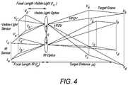
- FIG. 4is a diagram showing the optical path and sensor configuration of the camera.
- FIG. 5shows geometrically, the derivation of the parallax equation.
- FIG. 6shows the (Full-Screen, Full-Sensor infrared)/(Full-Screen, Partial-Sensor Visible-Light) scene display mode.
- FIG. 7shows combined visible-light and infrared images uncorrected for parallax error.
- FIG. 8shows the same images corrected for parallax error.
- FIGS. 9 and 10are cross-sectional views of an infrared camera module with a magnet and Hall-Effect sensor according to an embodiment of the invention.
- FIG. 11shows the (Partial-Screen, Partial-Sensor infrared)/(Full-Screen, Full-Sensor Visible-Light) scene display mode.
- the camerauses all of the visible-light sensor elements to fill the display.
- FIG. 12shows the (Partial-Screen, Full-Sensor infrared)/(Full-Screen, Partial-Sensor Visible-Light) scene display mode.
- the camerauses all of the available infrared sensor elements to provide an infrared image that fills only a central area of the camera display.
- FIG. 13shows the (Partial-Screen, Full-Sensor infrared)/(Full-Screen, Full-Sensor Visible-Light) scene display mode.
- the camerauses all of the infrared and all of the visible-light sensor elements to construct the displayed images.
- FIGS. 14-16show respectively, an infrared only image of an insulated cup, a visible-light only image of the cup and a partial alpha-blended image of the cup.
- FIG. 17shows an example of a “hot threshold” alarm mode display.
- FIG. 18shows a typical infrared image of a low infrared contrast scene.
- FIG. 19shows the same scene with an alpha-blended visible-light image, yielding a much higher apparent contrast.
- FIGS. 20-23show, respectively, a visible-light image with a laser spot, a visible-light image with the laser spot and a computer generated laser marker aligned with the laser spot, an infrared only image with the computer generated laser marker and hot spot not aligned, and an infrared only image with the computer generated laser marker and hot spot aligned.
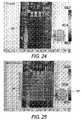
- FIGS. 24-26show, respectively, a visible-light only image with a laser point, an alpha-blended visible-light/infrared image with a laser point and hot spot not aligned, and an alpha-blended visible-light/infrared image with a laser point spot aligned.
- FIGS. 27-28show, respectively, an infrared only image with a computer generated laser pointer and hot spot not aligned and an infrared only image with the computer generated laser pointer and hot spot aligned.
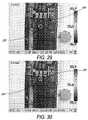
- FIGS. 29-30show, respectively, a visible-light only image with a laser spot and a computer generated laser marker not aligned and a visible-light only image with the laser spot and computer generated laser marker aligned.
- FIGS. 1 and 2are perspective views of the front and the back of a camera 10 according to an embodiment of the invention.
- the housingincludes an infrared camera module and a visible-light camera module.
- the camera 10includes a camera housing 12 , a Visible-Light (VL) lens 13 , an infrared lens 14 , focus ring 16 and a laser pointer 18 as well as various electronics located within the housing as will be described with reference to FIG. 3 .
- an LED torch/flash 17is located on each side of the VL lens 13 to aid in providing enough light in dark environments.
- a display 20is located on the back of the camera so that infrared images, visible light images and/or blended images of Infrared and Visible-Light may be viewed.
- target site temperatureincluding temperature measurement spot size
- distance readingsmay be displayed.
- user controls 22are also located on the back of the camera to control the display mode and activate or deactivate the laser pointer.
- FIG. 3shows a block diagram of a representative camera system according to an embodiment of the invention that can be used to practice embodiments of the invention.
- the Visible-Light camera moduleincludes a CMOS, CCD or other types of visible-light camera, LED torch/flash and a laser pointer. This camera streams RGB image display data (e.g. 30 Hz) to the FPGA for combination with infrared RGB image data and then sends the combined image data to the display.
- RGB image display datae.g. 30 Hz
- the Analog Engineinterfaces with and controls the infrared sensor, and streams raw infrared image data (e.g. 30 Hz) to the DSP.
- the DSPperforms computations to convert the raw infrared image data to scene temperatures, and then to RGB colors corresponding to the scene temperatures and selected color palette.
- the DSPthen streams the resulting infrared RGB image display data to the FPGA where it is combined with the VL RGB image data and then sends the combined image data to the display.
- the Embedded Processor Card Engineincludes a general-purpose microprocessor that provides a graphical user interface (GUI) to the camera operator.
- GUIgraphical user interface
- This GUI interfaceconsists of menus, text, and graphical display elements that are sent to the FPGA, where they are buffered in SRAM and then sent to the display.
- the MSP430interfaces with the user interface including camera buttons, mouse, LCD backlight, and the smart battery. It reads these inputs and provides the information to the embedded processor card engine where it is used to control the GUI and provides other system control functions.
- the FPGAdrives the display(s) (LCD and/or TV, for example) with combined visible-light image data, infrared image data, and GUI data.
- the FPGArequests both the visible-light and infrared image data from the VL and infrared camera modules and alpha-blends them together. It also alpha-blends the resulting display image with the GUI data to create a final blended image that is sent to the LCD display.
- the display associated with the embodiments of the inventionis not limited to an LCD-type display.
- the FPGAoperates under control of the DSP, which is further controlled by the embedded processor card engine.
- the degree of image alpha-blending and the display modei.e. picture-in-a-picture, full screen, color alarm and zoom mode, is controlled by the user through the GUI. These settings are sent from the embedded processor card engine to the DSP which then configures the FPGA properly.
- Embodiments of the inventioncombine an engine of a real-time visible-light camera with an engine of a real-time infrared camera close to each other in the same housing such that the optical axes are roughly parallel to each other.
- the cameraplaces the engine or module of a real-time visible-light camera in the housing of a real-time infrared camera.
- the placementis such that the visible and infrared optical axes are as close as practical and roughly parallel to each other, for example, in the vertical plane of the infrared optical axis.
- the visible light camera modulei.e., VL optics and VL sensor array, are chosen to have a larger field of view (FOV) than the infrared camera module.
- FIG. 4is a diagram showing the optical path and sensor configuration of the camera. As shown in the diagram, there are two distinct optical paths and two separate sensors. One for visible-light, and one for infrared.
- the parallax erroris corrected electronically using software manipulations.
- Thisprovides the capability to electronically correct the displayed images for parallax.
- the visible-light optics and sensorare chosen so that their respective field of views (FOV) are different, i.e. one is larger than the other.
- FOVfield of views
- the VL FOVis greater than the infrared FOV.
- the visible light opticsare such that the visible light camera module remains in focus at all usable distances. Only the infrared lens needs focus adjustment for targets at different distances.
- FIG. 5shows geometrically, the derivation of the parallax equation (eq. 1).
- parallaxcan be reduced by minimizing the distance (q) between the visible-light and infrared optical apertures, and also by choosing short focal length lenses.
- the camera designwill typically physically fix (q).
- the focal lengths of the visible-light and infrared lens (f)can be altered in the field by changing lenses, or using optical systems that include multiple focal lengths or continuous zoom. In the embodiments with fixed focal length lenses, the focal lengths remain constant during operation once the lenses are installed. Hence, during camera operation, parallax is simply a function of distance (d) to the target.
- the focal length (f) of each lensis the same.
- the focal lengths (f) of the infrared lens and the visible lensmay differ from each other.
- parallax error correctionsare based on the infrared focus distance as will be described hereinafter.
- parallax errormay also be corrected by determining the distance from the target image (other than via focus distance) by schemes known to those of ordinary skill in the art.
- the camera according to the embodiments of the inventioncan operate in one of three display modes; 1) full screen visible, infrared and/or blended, 2) picture-in-a-picture such as partial infrared image in a full screen visible image, and 3) infrared color alarms in visible-light images.
- temperatureswill be recorded and can be displayed in the infrared portion of the image. Temperatures can also be displayed on a visible-light only image from the recorded but not displayed infrared image.
- the displayis about 320 by 240 pixels and is represented by the dashed-line box shown in FIG. 6 .
- the infrared sensorhas 160 by 120 pixels and the visible-light sensor has 1280 by 1024 pixels.
- FIG. 6shows a diagram of the mode where the full 160 by 120 infrared image is interpolated to fill the camera display. Based on the display mode chosen, a portion of the 1280 by 1024 visible-light image is windowed to match the infrared window. Since the number of selected visible-light sensor elements does not necessarily match the 320 by 240 pixels of the camera display, the visible-light image is scaled to match the camera display. After parallax error correction, each resulting infrared display pixel will represent the same instantaneous field of view (IFOV) as its corresponding visible-light display pixel.
- IFOVinstantaneous field of view
- the camera operatorcan easily identify points-of-interest in the infrared image with objects in the visible-light image simply by noting where the features of interest overlie each other in the two images.
- the display modeis entitled “Full-Screen, Full-Sensor Infrared and Full-Screen, Partial-Sensor Visible-Light display mode.” Additional display modes are discussed further below.
- FIGS. 9 and 10show a sectional view of camera 10 taken from front to rear through the center of infrared lens 14 .
- a Hall-Effect sensor 30is fixed in the housing 32 with respect to the infrared sensor array 34 to sense the proximity of a magnet 36 attached to the back of the IR lens 14 .
- the distance f′ between the magnet 36 and the Hall-Effect sensor 30changes, resulting in an output from the Hall-Effect sensor that is proportional to focus position.
- the focus of the lenscould be changed by moving the lens or moving the infrared sensor array.
- This focus positionis used to derive an estimate of the distance to the target.
- the infrared lens focus positionprovides an especially convenient estimate of distance because typical infrared lenses have a low F-number, resulting in a shallow depth of field.
- the Hall-Effect sensormay, in one embodiment, be fixed on the infrared sensor array. In addition, the positions of the Hall-Effect sensor and magnet may be reversed from that shown.
- the magnet 36is a ring that encircles an interior surface of the focus ring 16 facing the infrared sensor array 34 .
- the Hall-Effect sensor 30is fixed in the camera housing 32 a small distance from of the infrared sensor array 34 .
- the distance between the Hall-Effect sensor and the magnetrepresents the distance f′ shown in FIGS. 9 and 10 .
- FIG. 9shows the lens positioned for near focus
- FIG. 10shows the lens positioned for far focus in which case the magnet is closer to the Hall-Effect sensor than in FIG. 9 .
- Mechanisms and methods other than those described above for a Hall effect sensormay, of course, be employed to determine the distance to target. Such equivalent mechanisms or methods would be known to those with skill in the art.
- the Hall-Effect sensoris one convenient method.
- Estimating the distance between the target and the camerais a valuable safety feature.
- OSHAhas specific safety distance requirements when inspecting high voltage electrical cabinets.
- spot sizecan be calculated as a function of distance and displayed to the camera operator via the display.
- the lens position sensor value to focus distance correlation for each infrared lensis determined at the factory and stored with other camera calibration data in the camera's non-volatile memory.
- This calibration dataincludes X and Y image offsets calculated for each focus distance.
- the correct X and Y sensor offsets of the partial area from the visible-light sensor to be displayedcan be computed and used to select the appropriate visible-light sensor area for the current infrared focus distance. That is, as the focus distance of the infrared lens is changed, different areas of the visible-light sensor image are extracted and displayed, resulting in registration of the infrared and visible-light images for objects at the focus distance.
- FIG. 7shows combined picture-in-a-picture display of visible-light and infrared images misaligned, i.e. uncorrected for parallax error.
- FIG. 8shows the same images corrected for parallax error.
- the center quarter of the displayshows a blurry (unfocused) and unregistered infrared-only image 40 placed within the surrounding framework of a visible only image 42 .
- the rectangular dark sections 44 in the imageare misaligned (unregistered) showing the parallax error resulting from the unfocused infrared image 44 .
- FIGS. 7 and 8highlight a method by which a user of camera 10 could focus the infrared image 40 by merely rotating focus ring 16 until image 40 is properly registered.
- FIGS. 7 and 8show the center quarter of the display as infrared only, this same method and technique could be used for a blended visible and infrared image, whether the images are shown picture in picture, full display, alarm mode, or other display modes.
- parallax errorbecomes negligible beyond a focus distance of approximately 8 feet for lenses used with typical infrared cameras. Also note that parallax errors can only be corrected down to a limited close focus distance to the camera (typically about 2 feet). This distance is determined by how much “extra” field of view the visible-light sensor provides as compared to the infrared sensor.
- the full visible-light image and the full infrared image with all of the ancillary dataare saved in an image file on the camera memory card. That part of the visible-light image not displayed which lies outside of the camera display dimensions when the image was taken is saved as part of the visible-light image. Later, if an adjustment in the registration between the infrared and visible-light image is needed, either in the camera or on a computer, the full visible-light image is available.
- the cameraallows the operator to adjust the registration of the visible-light and infrared image after an infrared/Visible-light image pair is captured and stored in memory.
- One way to accomplish thisis to use the infrared lens position as an input control. This allows the operator to fine-tune the registration, or to manually register objects in the scene that were not at the infrared focus distance when the images were captured, simply by rotating the focus ring on the lens.
- the visible-light imagewhen it is the only displayed image, is displayed preferably in color, although it need not be.
- the visible-light imageis converted to gray scale before it is blended so that it only adds intensity to the colored infrared image.
- FIG. 11shows the scene display mode entitled “Partial-Screen, Full-Sensor Infrared and Full-Screen, Partial-Sensor Visible-Light display mode.”
- the camerauses all of the available infrared sensor elements to provide an infrared image that fills only a central area of the camera display.
- Standard image processing techniquese.g. scaling and windowing, for example
- the IFOV of the visible-light imageis adjusted to match the IFOV of the infrared image and then a portion of the visible-light image is selected to fill the full display and to match the infrared image in the center of the display.
- the center quarter of the display can be infrared only, visible-light only or a blend of the two.
- the remaining three-quarters of the display (outer framework)is visible-light only.
- the camerauses the same technique in this mode as that described for the full screen mode to correct for parallax.
- FIGS. 12 and 13illustrate this technique.
- FIG. 12shows a picture-in-a-picture “Partial-Screen, Partial-Sensor infrared and Full-Screen, Full-Sensor Visible-Light scene display mode.”
- the camerauses all of the visible-light sensor elements to fill the display. If the number of visible-light sensor elements does not match the number of display pixels, the camera uses standard imaging techniques to create an image that fills the display screen. A portion of the available infrared sensors is chosen to provide the infrared image. The infrared image is windowed and matched so that the resulting infrared display pixels provide the same IFOV as the visible-light image display pixels.
- the camerauses similar techniques to those described for FIG. 6 to correct for parallax. However, in this mode, different areas of the infrared sensor are selected to match the center region of the visible-light image as the infrared focus distance is changed. Note that in this mode, the infrared image is always displayed in a fixed position in the middle of the display.
- FIG. 13shows the “Partial-Screen, Full-Sensor infrared and Full-Screen, Full-Sensor Visible-Light scene display mode.”
- the camerauses all of the infrared and all of the visible-light sensor elements to construct the displayed images.
- the visible-light imageis scaled to completely fill the display.
- the infrared imageis windowed and scaled so that the IFOV of the resulting display pixels match the visible-light image.
- the resulting imageis displayed over the matching area of the visible-light image.
- parallaxis corrected by moving the infrared image scene to align it with the visible-light image scene.
- FIGS. 14-16show respectively, an infrared only image of an insulated cup, a visible light (VL) only image of the cup, and a partial alpha-blending of the infrared and VL images.
- the camerawill enable the operator to adjust the alpha blending of the visible and infrared images from the extremes of infrared-only ( FIG. 14 ) or visible-only ( FIG. 15 ) to any combination of alpha blending between these two extremes ( FIG. 16 ).
- the infrared imageis not visible in FIG. 15
- the underlying infrared image datais used to display the correct object temperature 52 in the visible light image.
- the temperature 52 associated with the cursor's location on the imageis displayed.
- the infrared and visible-light imagescan be displayed in either color or grayscale.
- coloris used to portray temperatures in the infrared image
- the visible image in the overlap areacan be displayed in grayscale only so that it doesn't excessively corrupt the infrared palette colors.
- both the visible and infrared imagesare saved individually so reconstructing images with different alpha blending can be accomplished later either in the camera, or with PC software.
- the camerasupports several different visual alarm modes. These modes are used to call the operator's attention to areas of interest in the visible-light image by displaying an alpha-blended or infrared only image in areas that meet the alarm criteria as set by the user.
- FIG. 17shows an example of the “hot threshold” alarm mode. Only those pixels in the infrared image that exceed a set temperature threshold (hotspots 60 ) are displayed. In the color alarm mode, the visible-light image 62 is switched to gray scale so that the infrared image stands out with no ambiguity.
- the cameracan provide alarm modes, such as those described below. Other alarm modes are also possible.
- the alarm modes identified abovemay also be indicated audibly or via vibration. Such audible or vibrational alarms may be useful in situations where hotspots are small enough to otherwise go unnoticed in the visual display.
- the cameracan generate such an alarm to alert the camera operator when, for instance, the camera detects an out of specification temperature or any of the other alarms modes identified above.
- the cameramay include an alarm module connected to the FPGA that provides audible or vibrational alarms.
- the vibration mechanismcan be similar to that used in cellular phones to alert persons of an incoming call.
- All of the image display techniques described for the cameracan also be implemented in software that runs on a PC host computer and can be applied to images captured by the camera.
- the infrared imagewill not only be sharper with much more detail, it will be surrounded with a visual image showing exactly what and where the infrared targets are. Parallax error will be automatically corrected, yielding a visible-light control image that is correctly registered with the infrared image.
- Infrared camerascan be made with smaller less expensive detector arrays, yet display the apparent detail and contrast of very expensive infrared cameras with large and ultra-sensitive detector arrays.
- FIG. 18shows a typical infrared image of a low infrared contrast scene.
- FIG. 19shows the same scene with an alpha-blended visible-light image, yielding a much higher apparent contrast with target site temperature measurement.
- This cameracan be used in all phases of infrared thermography where current infrared cameras are used today and in the future.
- the cameracan be made inexpensively with a small infrared detector array and yet have very high performance—high image quality with high spatial resolution and accurate temperature.
- the cameracan be made at a lower cost and have images with greater apparent detail than the most expensive infrared cameras. The camera will eliminate the need to take separate visible-light images to be included in thermography reports.
- the laser pointer radiationis in the visible spectrum, it is not visible in the infrared image. As a result, the laser pointer is of limited value in infrared cameras. This is problematic when the location of a hot or cold spot is difficult to identify. For example, large industrial control panels often have many components that are similar in shape and packed tightly together. It is sometimes difficult to determine the exact component that is causing a hot spot in the infrared camera image.
- the laser pointer of the embodiments of the inventioncan be used to identify the exact location of the defect on the wall.
- the thermographercan greatly aid the thermographer in marking the area suspected of needing repair.
- the camera operatorcan outline the wet area by adjusting the camera pointing so that the laser spot seen in the image outlines the suspected wet area in the image and thus also outlines the suspected wet area on the roof with the laser beam so that it can be correctly marked.
- the laser pointer embodiments of the inventionmay aid in identifying the location of the infrared point of interest.
- the laser pointer of the embodiments of the inventionis used to accurately identify the location of infrared points-of-interest and to easily aid the focusing of the infrared optics.
- FIGS. 24-26show an associated sequence of events.
- the laser pointercan be turned on using one of the camera's programmable buttons or by other mechanisms by the camera operator. At a reasonable distance, the laser pointer spot 100 on the target can be seen in the visible-light image ( FIG. 24 ) and in the blended visible-light and infrared image that has been corrected for parallax error ( FIG. 25 ). Once the laser spot is identified in the blended image ( FIG. 25 ), the camera operator can adjust the camera pointing until the laser spot in the blended image matches the spot of interest 102 in the infrared image ( FIG. 26 ). The laser beam then marks the target at the point-of-interest ( FIG. 26 ).
- the camera according to the embodiments of the inventionhas been calibrated in the factory to identify the location of the laser spot in the infrared image using parallax calibration data as a function of infrared camera module focus distance, the camera operator does not need to see displayed the laser spot in the VL image. If the target is at a distance and/or has a low reflection for the laser wavelength, the laser spot may be too weak for the VL camera to show prominently on the camera display but it can still be seen on the target by the human observer.
- FIGS. 27 and 28show an associated sequence of events. In this case, the infrared focus is adjusted as normally done by observing the sharpness of the infrared image.
- a computer-generated laser spot reference mark 200is registered with the infrared image so that a representative mark (e.g., circle) is displayed on the infrared image ( FIG. 27 ).
- the camera operatorthen adjusts the camera pointing until the laser calibration mark 200 lies over the infrared point-of-interest 202 ( FIG. 28 ). Once that happens, the laser beam then strikes the target at the point of interest.
- the camera operatorfirst focuses the infrared image using an infrared display image only, switches to the visible-light display where the laser 210 will be shown in the display as seen in FIG. 20 .
- the operatormarks the laser spot 210 on the display with a marking 212 such as a circle (see FIG. 21 ) and then switches the display back to the infrared only (see FIG. 22 ) where the marking 212 is registered with the infrared image and it is displayed on the infrared image, positioned in the center quarter of the display area.
- the operatorthen adjusts the camera pointing so that the mark 212 on the infrared display matches the thermal spot of interest 214 on the infrared display. (see FIG. 23 ) Once that happens, the laser beam then strikes the target at the point of interest.
- FIGS. 29 and 30show an associated sequence of events.
- the location of the laser spot 220is visible in the VL image ( FIG. 29 ).
- the camera according to the embodiments of the inventionhas been calibrated in the factory to generate a computer-generated laser spot reference mark 222 that indicates the location of the laser spot in a focused infrared image using parallax calibration data as a function of infrared camera module focus distance.
- This reference markmay be displayed in the IR image or the VL image (that overlaps the IR image).
- the reference mark 222is shown in the VL only image.
- the markmoves in the VL image showing the spot where the laser dot would be in the infrared image.
- the focus adjustmentmay stop and the infrared camera module is in focus. This allows the most novice operator to focus the infrared lens and eliminates the subjective nature of focusing.
Landscapes
- Engineering & Computer Science (AREA)
- Physics & Mathematics (AREA)
- General Physics & Mathematics (AREA)
- Spectroscopy & Molecular Physics (AREA)
- Multimedia (AREA)
- Signal Processing (AREA)
- Human Computer Interaction (AREA)
- Electromagnetism (AREA)
- Radar, Positioning & Navigation (AREA)
- Remote Sensing (AREA)
- Studio Devices (AREA)
- Closed-Circuit Television Systems (AREA)
- Radiation Pyrometers (AREA)
Abstract
Description
- Absolute hot threshold—infrared pixels above a defined temperature are alpha-blended with corresponding visible-image pixels.
- Absolute cold threshold—infrared pixels below a defined temperature are alpha-blended with corresponding visible-image pixels.
- Relative hot threshold—A temperature range is defined by the user. The temperature range is relative to the current hottest pixel (or average of a set number of hottest pixels) in the scene or from a previous scene or reference scene. Infrared pixels above the threshold defined by the current hottest pixel(s) in the scene minus a user defined or predetermined temperature range are alpha-blended with their corresponding visible-image pixels. For example, if the temperature range is 5 degrees, and the current hottest pixel(s) in the scene is 100 degrees, for example, all infrared pixels above 95 degrees in the scene will be alpha-blended with corresponding visible-light pixels.
- Relative cold threshold—A temperature range is defined by the user. The temperature range is relative to the current coldest pixel (or average of a set number of coldest pixels) in the scene or from a previous scene or reference scene. Infrared pixels below the threshold defined by the current coldest pixel(s) in the scene plus a user defined or predetermined temperature range are alpha-blended with their corresponding visible-image pixels. For example, if the temperature range is 5 degrees, and the current coldest pixel(s) in the scene is 10 degrees, all infrared pixels below 15 degrees in the scene will be alpha-blended with corresponding visible-light pixels.
- Absolute range (isotherm)—The operator enters a temperature range. Infrared pixels with a temperature within the set range are alpha-blended with their corresponding visible-light pixels. For example, the user enters a range of 80-100 degrees. All infrared pixels with a temperature value within the 80-100 degree range are alpha-blended.
- Alarm flash mode—To further call attention to areas of interest, the camera may provide a mode whereby the alpha-blended areas are “flashed” by alternately displaying the alarmed pixels as visible-light only, and then either alpha-blended or infrared only.
Claims (23)
Priority Applications (8)
| Application Number | Priority Date | Filing Date | Title |
|---|---|---|---|
| US11/294,752US7538326B2 (en) | 2004-12-03 | 2005-12-05 | Visible light and IR combined image camera with a laser pointer |
| US11/458,600US7994480B2 (en) | 2004-12-03 | 2006-07-19 | Visible light and IR combined image camera |
| US11/625,140US7535002B2 (en) | 2004-12-03 | 2007-01-19 | Camera with visible light and infrared image blending |
| US12/176,853US8531562B2 (en) | 2004-12-03 | 2008-07-21 | Visible light and IR combined image camera with a laser pointer |
| US12/543,252US8466422B2 (en) | 2004-12-03 | 2009-08-18 | Visible light and IR combined image camera |
| US13/963,802US9635282B2 (en) | 2004-12-03 | 2013-08-09 | Visible light and IR combined image camera |
| US15/466,895US20170195548A1 (en) | 2004-12-03 | 2017-03-23 | Visible light and ir combined image camera |
| US16/436,010US11032492B2 (en) | 2004-12-03 | 2019-06-10 | Visible light and IR combined image camera |
Applications Claiming Priority (2)
| Application Number | Priority Date | Filing Date | Title |
|---|---|---|---|
| US63307804P | 2004-12-03 | 2004-12-03 | |
| US11/294,752US7538326B2 (en) | 2004-12-03 | 2005-12-05 | Visible light and IR combined image camera with a laser pointer |
Related Child Applications (3)
| Application Number | Title | Priority Date | Filing Date |
|---|---|---|---|
| US11/458,600ContinuationUS7994480B2 (en) | 2004-12-03 | 2006-07-19 | Visible light and IR combined image camera |
| US11/625,140Continuation-In-PartUS7535002B2 (en) | 2004-12-03 | 2007-01-19 | Camera with visible light and infrared image blending |
| US12/176,853Continuation-In-PartUS8531562B2 (en) | 2004-12-03 | 2008-07-21 | Visible light and IR combined image camera with a laser pointer |
Publications (2)
| Publication Number | Publication Date |
|---|---|
| US20060289772A1 US20060289772A1 (en) | 2006-12-28 |
| US7538326B2true US7538326B2 (en) | 2009-05-26 |
Family
ID=36565823
Family Applications (3)
| Application Number | Title | Priority Date | Filing Date |
|---|---|---|---|
| US11/294,752ActiveUS7538326B2 (en) | 2004-12-03 | 2005-12-05 | Visible light and IR combined image camera with a laser pointer |
| US11/458,600Active2029-04-08US7994480B2 (en) | 2004-12-03 | 2006-07-19 | Visible light and IR combined image camera |
| US12/543,252Active2028-08-04US8466422B2 (en) | 2004-12-03 | 2009-08-18 | Visible light and IR combined image camera |
Family Applications After (2)
| Application Number | Title | Priority Date | Filing Date |
|---|---|---|---|
| US11/458,600Active2029-04-08US7994480B2 (en) | 2004-12-03 | 2006-07-19 | Visible light and IR combined image camera |
| US12/543,252Active2028-08-04US8466422B2 (en) | 2004-12-03 | 2009-08-18 | Visible light and IR combined image camera |
Country Status (4)
| Country | Link |
|---|---|
| US (3) | US7538326B2 (en) |
| EP (1) | EP1831657B1 (en) |
| CN (1) | CN101111748B (en) |
| WO (1) | WO2006060746A2 (en) |
Cited By (67)
| Publication number | Priority date | Publication date | Assignee | Title |
|---|---|---|---|---|
| US20070206840A1 (en)* | 2006-03-03 | 2007-09-06 | Honeywell International Inc. | Modular biometrics collection system architecture |
| US20080075334A1 (en)* | 2003-09-05 | 2008-03-27 | Honeywell International Inc. | Combined face and iris recognition system |
| US20080084472A1 (en)* | 2006-10-10 | 2008-04-10 | Itt Manufacturing Enterprises, Inc. | System and method for dynamically correcting parallax in head borne video systems |
| US20080267253A1 (en)* | 2004-04-14 | 2008-10-30 | Baraldi Chemgroup Srl | Method to Optimise Temperature Regulation in Technological Processes |
| US20090052037A1 (en)* | 2007-08-24 | 2009-02-26 | Mats Goran Henry Wernersson | Optical device stabilizer |
| US20090050806A1 (en)* | 2004-12-03 | 2009-02-26 | Fluke Corporation | Visible light and ir combined image camera with a laser pointer |
| US20090092283A1 (en)* | 2007-10-09 | 2009-04-09 | Honeywell International Inc. | Surveillance and monitoring system |
| US20100034529A1 (en)* | 2008-08-07 | 2010-02-11 | Honeywell International Inc. | Predictive autofocusing system |
| US20100046577A1 (en)* | 2008-08-21 | 2010-02-25 | Fluke Corporation | Thermal instrument engine |
| US20100240140A1 (en)* | 2005-07-27 | 2010-09-23 | L-3 Communications Corporation | Energetic material detector |
| US20100239119A1 (en)* | 2006-03-03 | 2010-09-23 | Honeywell International Inc. | System for iris detection tracking and recognition at a distance |
| US20100316263A1 (en)* | 2009-06-15 | 2010-12-16 | Honeywell International Inc. | Iris and ocular recognition system using trace transforms |
| US20100315500A1 (en)* | 2009-06-15 | 2010-12-16 | Honeywell International Inc. | Adaptive iris matching using database indexing |
| US8045764B2 (en) | 2005-01-26 | 2011-10-25 | Honeywell International Inc. | Expedient encoding system |
| US8050463B2 (en) | 2005-01-26 | 2011-11-01 | Honeywell International Inc. | Iris recognition system having image quality metrics |
| US8063889B2 (en) | 2007-04-25 | 2011-11-22 | Honeywell International Inc. | Biometric data collection system |
| US8090157B2 (en) | 2005-01-26 | 2012-01-03 | Honeywell International Inc. | Approaches and apparatus for eye detection in a digital image |
| US8090246B2 (en) | 2008-08-08 | 2012-01-03 | Honeywell International Inc. | Image acquisition system |
| US8098901B2 (en) | 2005-01-26 | 2012-01-17 | Honeywell International Inc. | Standoff iris recognition system |
| US8253619B2 (en) | 2005-02-15 | 2012-08-28 | Techtronic Power Tools Technology Limited | Electromagnetic scanning imager |
| US8280119B2 (en) | 2008-12-05 | 2012-10-02 | Honeywell International Inc. | Iris recognition system using quality metrics |
| US8285005B2 (en) | 2005-01-26 | 2012-10-09 | Honeywell International Inc. | Distance iris recognition |
| US8292496B1 (en) | 2005-07-27 | 2012-10-23 | L-3 Communications Cyterra Corporation | Energetic material detector |
| WO2012177740A2 (en) | 2011-06-20 | 2012-12-27 | Fluke Corporation | Thermal imager that analyzes temperature measurement calculation accuracy |
| US8374438B1 (en)* | 2007-10-04 | 2013-02-12 | Redshift Systems Corporation | Visual template-based thermal inspection system |
| US20130053101A1 (en)* | 2007-08-31 | 2013-02-28 | Richard Tsai | Video Mode Hidden Autofocus |
| US8436907B2 (en) | 2008-05-09 | 2013-05-07 | Honeywell International Inc. | Heterogeneous video capturing system |
| US8442276B2 (en) | 2006-03-03 | 2013-05-14 | Honeywell International Inc. | Invariant radial iris segmentation |
| US8619167B2 (en) | 2010-04-28 | 2013-12-31 | Microsoft Corporation | Scanned beam display and image capture |
| US8742887B2 (en) | 2010-09-03 | 2014-06-03 | Honeywell International Inc. | Biometric visitor check system |
| US8760509B2 (en) | 2010-12-31 | 2014-06-24 | Fluke Corporation | Thermal imager with non-uniformity correction |
| US20140267768A1 (en)* | 2013-03-15 | 2014-09-18 | Mu Optics, Llc | Thermographic Camera Accessory for Personal Electronics |
| US8902302B2 (en) | 2011-09-16 | 2014-12-02 | Emerson Electric Co. | Method and apparatus for surveying with a feature location |
| RU2563557C2 (en)* | 2014-02-24 | 2015-09-20 | Открытое Акционерное Общество "Научно-Производственный Комплекс "Дедал" | Multispectral system and method for electro-optical surveillance of protected area |
| EP2938061A1 (en) | 2014-04-22 | 2015-10-28 | Fluke Corporation | Methods for end-user parallax adjustment |
| US9204062B2 (en) | 2011-08-24 | 2015-12-01 | Fluke Corporation | Thermal imaging camera with range detection |
| USD766757S1 (en)* | 2015-03-19 | 2016-09-20 | Black & Decker Inc. | Laser tool |
| USD767419S1 (en)* | 2015-03-19 | 2016-09-27 | Black & Decker Inc. | Laser tool |
| US9538880B2 (en)* | 2012-05-09 | 2017-01-10 | Convotherm Elektrogeraete Gmbh | Optical quality control system |
| US9723229B2 (en) | 2010-08-27 | 2017-08-01 | Milwaukee Electric Tool Corporation | Thermal detection systems, methods, and devices |
| US20170258331A1 (en)* | 2014-09-08 | 2017-09-14 | Shimadzu Corporation | Imaging device |
| US9883084B2 (en) | 2011-03-15 | 2018-01-30 | Milwaukee Electric Tool Corporation | Thermal imager |
| US9990730B2 (en) | 2014-03-21 | 2018-06-05 | Fluke Corporation | Visible light image with edge marking for enhancing IR imagery |
| WO2018158504A1 (en) | 2017-03-01 | 2018-09-07 | Thermidas Oy | Multimodal medical imaging and analyzing system, method and server |
| US10152811B2 (en) | 2015-08-27 | 2018-12-11 | Fluke Corporation | Edge enhancement for thermal-visible combined images and cameras |
| US20190072656A1 (en)* | 2017-09-07 | 2019-03-07 | Robert Bosch Gmbh | Method for Operating a Laser Distance Measurement Device |
| EP3480752A1 (en) | 2017-11-06 | 2019-05-08 | Fluke Corporation | Inspection workflow using object recognition and other techniques |
| EP3480618A2 (en) | 2017-11-02 | 2019-05-08 | Fluke Corporation | Multi-modal acoustic imaging tool |
| EP3480625A1 (en) | 2017-11-02 | 2019-05-08 | Fluke Corporation | Focus and/or parallax adjustment in acoustic imaging using distance information |
| EP3480567A1 (en) | 2017-11-02 | 2019-05-08 | Fluke Corporation | Portable acoustic imaging tool with scanning and analysis capability |
| US10375325B2 (en) | 2016-06-23 | 2019-08-06 | Fluke Corporation | Thermal anomaly detection |
| US10412280B2 (en) | 2016-02-10 | 2019-09-10 | Microsoft Technology Licensing, Llc | Camera with light valve over sensor array |
| WO2020023633A1 (en) | 2018-07-24 | 2020-01-30 | Fluke Corporation | Systems and methods for tagging and linking acoustic images |
| US10555603B2 (en) | 2016-11-28 | 2020-02-11 | Lumi Legend Corporation | Height adjustable workstation |
| US10794769B2 (en) | 2012-08-02 | 2020-10-06 | Milwaukee Electric Tool Corporation | Thermal detection systems, methods, and devices |
| US10839659B2 (en) | 2018-10-17 | 2020-11-17 | Arlo Technologies, Inc. | System for video monitoring with improved image quality |
| US10965889B2 (en) | 2011-06-20 | 2021-03-30 | Fluke Corporation | Thermal imager that analyzes temperature measurement calculation accuracy |
| US10972649B2 (en) | 2019-02-27 | 2021-04-06 | X Development Llc | Infrared and visible imaging system for device identification and tracking |
| US20220057269A1 (en)* | 2020-08-21 | 2022-02-24 | Analog Devices, Inc. | Multi-sensor using a thermal camera |
| WO2022056327A1 (en) | 2020-09-11 | 2022-03-17 | Fluke Corporation | System and method for acoustic imaging with an accumulated-time view |
| WO2022056330A2 (en) | 2020-09-11 | 2022-03-17 | Fluke Corporation | System and method for generating panoramic acoustic images and virtualizing acoustic imaging devices by segmentation |
| US11481883B2 (en)* | 2020-01-29 | 2022-10-25 | Abb Schweiz Ag | System for monitoring a switchgear |
| US20220377219A1 (en)* | 2021-05-18 | 2022-11-24 | Magna Electronics Inc. | Vehicular driver monitoring system with camera view optimization |
| US11520041B1 (en)* | 2018-09-27 | 2022-12-06 | Apple Inc. | Correcting depth estimations derived from image data using acoustic information |
| EP3115824B1 (en)* | 2015-06-18 | 2023-09-13 | Qioptiq Limited | Parallax correction device and method in blended optical system for use over a range of temperatures |
| US20240420477A1 (en)* | 2009-06-04 | 2024-12-19 | Optics Innovation Llc | Method and apparatus for a wearable computer |
| US12303228B2 (en) | 2009-06-04 | 2025-05-20 | Optics Innovation Llc | Method and apparatus for a compact and high resolution mind-view communicator |
Families Citing this family (256)
| Publication number | Priority date | Publication date | Assignee | Title |
|---|---|---|---|---|
| US20060078037A1 (en)* | 2003-04-16 | 2006-04-13 | Tzong-Sheng Lee | Thermometer with image display |
| DE102005006290A1 (en)* | 2005-02-11 | 2006-08-24 | Bayerische Motoren Werke Ag | Method and device for visualizing the surroundings of a vehicle by fusion of an infrared and a visual image |
| US7732768B1 (en)* | 2006-03-02 | 2010-06-08 | Thermoteknix Systems Ltd. | Image alignment and trend analysis features for an infrared imaging system |
| WO2007101275A1 (en)* | 2006-03-03 | 2007-09-07 | Honeywell International, Inc. | Camera with auto-focus capability |
| CN101496387B (en) | 2006-03-06 | 2012-09-05 | 思科技术公司 | System and method for access authentication in a mobile wireless network |
| JP4333685B2 (en)* | 2006-03-29 | 2009-09-16 | セイコーエプソン株式会社 | Camera, image display method and program thereof |
| JP4885612B2 (en)* | 2006-05-16 | 2012-02-29 | 日置電機株式会社 | thermometer |
| US8289372B2 (en)* | 2006-10-16 | 2012-10-16 | Flir Systems Ab | Method for displaying a thermal image in an IR camera and an IR camera |
| US9191583B2 (en) | 2006-10-16 | 2015-11-17 | Flir Systems Ab | Method for displaying a thermal image in an IR camera, and an IR camera |
| JP4949806B2 (en)* | 2006-11-10 | 2012-06-13 | オンセミコンダクター・トレーディング・リミテッド | Imaging apparatus and image signal processing apparatus |
| US20080170033A1 (en)* | 2007-01-15 | 2008-07-17 | International Business Machines Corporation | Virtual pointer |
| US20080224041A1 (en)* | 2007-03-16 | 2008-09-18 | Cannamela John J | Method and apparatus for subsurface anomaly detection and image projection |
| US7544944B2 (en) | 2007-07-02 | 2009-06-09 | Flir Systems Ab | Camera and method for use with camera |
| US7809258B2 (en)* | 2007-07-06 | 2010-10-05 | Flir Systems Ab | Camera and method for use with camera |
| US7826736B2 (en) | 2007-07-06 | 2010-11-02 | Flir Systems Ab | Camera and method for use with camera |
| US8208759B2 (en)* | 2007-08-29 | 2012-06-26 | Texas Instruments Incorporated | Light valve projection of visible image correlated with non-visible image |
| US7820967B2 (en)* | 2007-09-11 | 2010-10-26 | Electrophysics Corp. | Infrared camera for locating a target using at least one shaped light source |
| US8044991B2 (en)* | 2007-09-28 | 2011-10-25 | The Boeing Company | Local positioning system and method |
| US8102424B2 (en) | 2007-10-17 | 2012-01-24 | Fluke Corporation | Ergonomic configurations for thermal imaging cameras |
| USD585927S1 (en) | 2007-10-25 | 2009-02-03 | Fluke Corporation | Handheld thermal imager |
| US8212210B2 (en)* | 2008-02-04 | 2012-07-03 | Flir Systems Ab | IR camera and method for presenting IR information |
| US8797377B2 (en) | 2008-02-14 | 2014-08-05 | Cisco Technology, Inc. | Method and system for videoconference configuration |
| US7667198B2 (en)* | 2008-04-02 | 2010-02-23 | Flir Systems Ab | IR camera and a method for processing information in images |
| US8335996B2 (en)* | 2008-04-10 | 2012-12-18 | Perceptive Pixel Inc. | Methods of interfacing with multi-input devices and multi-input display systems employing interfacing techniques |
| US8390667B2 (en) | 2008-04-15 | 2013-03-05 | Cisco Technology, Inc. | Pop-up PIP for people not in picture |
| US20090262012A1 (en)* | 2008-04-16 | 2009-10-22 | Paul Carlson | Radiometer and temperature compensation system |
| DK3876510T3 (en) | 2008-05-20 | 2024-11-11 | Adeia Imaging Llc | CAPTURE AND PROCESSING OF IMAGES USING MONOLITHIC CAMERA ARRAY WITH HETEROGENEOUS IMAGES |
| US8866920B2 (en) | 2008-05-20 | 2014-10-21 | Pelican Imaging Corporation | Capturing and processing of images using monolithic camera array with heterogeneous imagers |
| US11792538B2 (en) | 2008-05-20 | 2023-10-17 | Adeia Imaging Llc | Capturing and processing of images including occlusions focused on an image sensor by a lens stack array |
| US7924312B2 (en)* | 2008-08-22 | 2011-04-12 | Fluke Corporation | Infrared and visible-light image registration |
| DE102008046963A1 (en)* | 2008-09-12 | 2010-06-10 | Siemens Aktiengesellschaft | Image recording unit for fusion of image of e.g. building, has signal processing unit receiving data processing signals from optical units, where signals are converted into signals of heat image based on visible image using preset formula |
| US8306279B2 (en)* | 2008-09-15 | 2012-11-06 | Eyelock, Inc. | Operator interface for face and iris recognition devices |
| US8694658B2 (en) | 2008-09-19 | 2014-04-08 | Cisco Technology, Inc. | System and method for enabling communication sessions in a network environment |
| JP5399674B2 (en)* | 2008-09-26 | 2014-01-29 | テルモ株式会社 | Infrared thermography apparatus and image processing method |
| JP2010103740A (en)* | 2008-10-23 | 2010-05-06 | Panasonic Corp | Digital camera |
| US7652251B1 (en) | 2008-11-17 | 2010-01-26 | Fluke Corporation | Registration methods for fusing corresponding infrared and visible light images |
| EP2683156A3 (en)* | 2008-12-12 | 2015-02-11 | Testo AG | Thermal imaging camera |
| US8595689B2 (en)* | 2008-12-24 | 2013-11-26 | Flir Systems Ab | Executable code in digital image files |
| US8167483B2 (en)* | 2009-01-15 | 2012-05-01 | Fluke Corporation | Temperature measurement instruments and methods for identifying a selected target area |
| JP5399738B2 (en)* | 2009-02-25 | 2014-01-29 | テルモ株式会社 | Infrared thermography device |
| JP5399737B2 (en)* | 2009-02-25 | 2014-01-29 | テルモ株式会社 | Infrared thermography device |
| US10757308B2 (en) | 2009-03-02 | 2020-08-25 | Flir Systems, Inc. | Techniques for device attachment with dual band imaging sensor |
| WO2015103448A2 (en)* | 2013-12-31 | 2015-07-09 | Flir Systems, Inc. | Techniques for device attachment with dual band imaging sensor |
| US9451183B2 (en)* | 2009-03-02 | 2016-09-20 | Flir Systems, Inc. | Time spaced infrared image enhancement |
| US8749635B2 (en)* | 2009-06-03 | 2014-06-10 | Flir Systems, Inc. | Infrared camera systems and methods for dual sensor applications |
| US8659637B2 (en) | 2009-03-09 | 2014-02-25 | Cisco Technology, Inc. | System and method for providing three dimensional video conferencing in a network environment |
| US8063367B2 (en)* | 2009-04-23 | 2011-11-22 | Fluke Corporation | Lens position sensor for infrared cameras |
| US8977528B2 (en) | 2009-04-27 | 2015-03-10 | The Boeing Company | Bonded rework simulation tool |
| US9108738B1 (en) | 2009-05-19 | 2015-08-18 | The Boeing Company | Apparatus for refueling aircraft |
| US8659639B2 (en) | 2009-05-29 | 2014-02-25 | Cisco Technology, Inc. | System and method for extending communications between participants in a conferencing environment |
| WO2013144298A1 (en)* | 2012-03-30 | 2013-10-03 | Flir Systems Ab | Facilitating analysis and interpretation of associated visible light and infrared (ir) image information |
| US10091439B2 (en) | 2009-06-03 | 2018-10-02 | Flir Systems, Inc. | Imager with array of multiple infrared imaging modules |
| US9716843B2 (en)* | 2009-06-03 | 2017-07-25 | Flir Systems, Inc. | Measurement device for electrical installations and related methods |
| US10044946B2 (en) | 2009-06-03 | 2018-08-07 | Flir Systems Ab | Facilitating analysis and interpretation of associated visible light and infrared (IR) image information |
| US9843743B2 (en)* | 2009-06-03 | 2017-12-12 | Flir Systems, Inc. | Infant monitoring systems and methods using thermal imaging |
| US8568545B2 (en) | 2009-06-16 | 2013-10-29 | The Boeing Company | Automated material removal in composite structures |
| CN101945224B (en)* | 2009-07-01 | 2015-03-11 | 弗卢克公司 | Thermography methods |
| US9082297B2 (en) | 2009-08-11 | 2015-07-14 | Cisco Technology, Inc. | System and method for verifying parameters in an audiovisual environment |
| US8384783B2 (en)* | 2009-09-29 | 2013-02-26 | Flir Systems Ab | Infrared camera and method for calculating output power value indicative of an amount of energy dissipated in an image view |
| RU2567213C2 (en)* | 2009-10-22 | 2015-11-10 | Конинклейке Филипс Электроникс Н.В. | Alignment of ordered stack of images of sample |
| EP2502115A4 (en) | 2009-11-20 | 2013-11-06 | Pelican Imaging Corp | CAPTURE AND IMAGE PROCESSING USING A MONOLITHIC CAMERAS NETWORK EQUIPPED WITH HETEROGENEOUS IMAGERS |
| US8599264B2 (en)* | 2009-11-20 | 2013-12-03 | Fluke Corporation | Comparison of infrared images |
| US8853631B2 (en) | 2009-11-23 | 2014-10-07 | Flir Systems Ab | Camera with two visual imaging subsystems for determining parallax and for focusing an infrared imaging subsystem |
| US8153971B2 (en)* | 2009-11-23 | 2012-04-10 | Flir Systems Ab | Camera with two visual imaging subsystems for determining parallax and for focusing an IR imaging subsystem |
| US9900524B2 (en)* | 2009-12-24 | 2018-02-20 | Flir Systems, Inc. | Cameras with on-board reporting capabilities |
| US9500555B2 (en)* | 2010-01-19 | 2016-11-22 | Clark Robert Gunness | Method and system for leak detection in roofing and waterproofing membranes |
| US9225916B2 (en)* | 2010-03-18 | 2015-12-29 | Cisco Technology, Inc. | System and method for enhancing video images in a conferencing environment |
| DE102010013377B4 (en)* | 2010-03-30 | 2012-02-02 | Testo Ag | Image processing method and thermal imaging camera |
| US9077915B2 (en)* | 2010-04-07 | 2015-07-07 | Projectiondesign As | Interweaving of IR and visible images |
| US8928793B2 (en) | 2010-05-12 | 2015-01-06 | Pelican Imaging Corporation | Imager array interfaces |
| US9313452B2 (en) | 2010-05-17 | 2016-04-12 | Cisco Technology, Inc. | System and method for providing retracting optics in a video conferencing environment |
| WO2011151803A2 (en)* | 2010-06-03 | 2011-12-08 | Aselsan Elektronik Sanayi Ve Ticaret Anonim Sirketi | An electro-optical detector device |
| US20110316697A1 (en)* | 2010-06-29 | 2011-12-29 | General Electric Company | System and method for monitoring an entity within an area |
| DE102010030928A1 (en) | 2010-07-05 | 2012-01-05 | Robert Bosch Gmbh | Non-contact measurement of a mean surface temperature of a measuring range |
| US8896655B2 (en) | 2010-08-31 | 2014-11-25 | Cisco Technology, Inc. | System and method for providing depth adaptive video conferencing |
| US8599934B2 (en) | 2010-09-08 | 2013-12-03 | Cisco Technology, Inc. | System and method for skip coding during video conferencing in a network environment |
| TWI468655B (en)* | 2010-10-07 | 2015-01-11 | Hon Hai Prec Ind Co Ltd | System and method for monitoring temperature |
| US8599865B2 (en) | 2010-10-26 | 2013-12-03 | Cisco Technology, Inc. | System and method for provisioning flows in a mobile network environment |
| US8699457B2 (en) | 2010-11-03 | 2014-04-15 | Cisco Technology, Inc. | System and method for managing flows in a mobile network environment |
| US9143725B2 (en) | 2010-11-15 | 2015-09-22 | Cisco Technology, Inc. | System and method for providing enhanced graphics in a video environment |
| US9338394B2 (en) | 2010-11-15 | 2016-05-10 | Cisco Technology, Inc. | System and method for providing enhanced audio in a video environment |
| US8730297B2 (en) | 2010-11-15 | 2014-05-20 | Cisco Technology, Inc. | System and method for providing camera functions in a video environment |
| US8902244B2 (en) | 2010-11-15 | 2014-12-02 | Cisco Technology, Inc. | System and method for providing enhanced graphics in a video environment |
| WO2012067282A1 (en)* | 2010-11-17 | 2012-05-24 | (주)이지템 | Mobile device and method for measuring temperature of thermal picture including body temperature |
| US8542264B2 (en) | 2010-11-18 | 2013-09-24 | Cisco Technology, Inc. | System and method for managing optics in a video environment |
| US8723914B2 (en) | 2010-11-19 | 2014-05-13 | Cisco Technology, Inc. | System and method for providing enhanced video processing in a network environment |
| US9111138B2 (en) | 2010-11-30 | 2015-08-18 | Cisco Technology, Inc. | System and method for gesture interface control |
| US8379123B2 (en) | 2010-12-13 | 2013-02-19 | Research In Motion Limited | System and method of capturing low-light images on a mobile device |
| US9952316B2 (en) | 2010-12-13 | 2018-04-24 | Ikegps Group Limited | Mobile measurement devices, instruments and methods |
| US20130335559A1 (en)* | 2010-12-13 | 2013-12-19 | Surveylab Group Limited | Mobile measurement devices, instruments and methods |
| US8878950B2 (en) | 2010-12-14 | 2014-11-04 | Pelican Imaging Corporation | Systems and methods for synthesizing high resolution images using super-resolution processes |
| CN102128686B (en)* | 2010-12-14 | 2012-11-21 | 天津理工大学 | Infrared microscopic thermodetector |
| USD682854S1 (en) | 2010-12-16 | 2013-05-21 | Cisco Technology, Inc. | Display screen for graphical user interface |
| DE102011010469A1 (en)* | 2011-02-05 | 2012-08-09 | Testo Ag | Method for generating composite image from two individual images for infrared camera, involves determining overlapping regions and/or image transformation rules for registering images in overlapping regions by comparing other images |
| EP2679000B1 (en)* | 2011-02-25 | 2016-11-02 | Photonis Netherlands B.V. | Acquiring and displaying images in real-time |
| US8692862B2 (en) | 2011-02-28 | 2014-04-08 | Cisco Technology, Inc. | System and method for selection of video data in a video conference environment |
| US8670019B2 (en) | 2011-04-28 | 2014-03-11 | Cisco Technology, Inc. | System and method for providing enhanced eye gaze in a video conferencing environment |
| US8786631B1 (en) | 2011-04-30 | 2014-07-22 | Cisco Technology, Inc. | System and method for transferring transparency information in a video environment |
| US20120284124A1 (en)* | 2011-05-06 | 2012-11-08 | Harangozo Matej | Building energy performance/improvements |
| EP2708019B1 (en) | 2011-05-11 | 2019-10-16 | FotoNation Limited | Systems and methods for transmitting and receiving array camera image data |
| US8934026B2 (en) | 2011-05-12 | 2015-01-13 | Cisco Technology, Inc. | System and method for video coding in a dynamic environment |
| US20130070060A1 (en) | 2011-09-19 | 2013-03-21 | Pelican Imaging Corporation | Systems and methods for determining depth from multiple views of a scene that include aliasing using hypothesized fusion |
| CN104081414B (en) | 2011-09-28 | 2017-08-01 | Fotonation开曼有限公司 | Systems and methods for encoding and decoding light field image files |
| US8947493B2 (en) | 2011-11-16 | 2015-02-03 | Cisco Technology, Inc. | System and method for alerting a participant in a video conference |
| CN102393561B (en)* | 2011-11-21 | 2015-03-25 | 无锡亮源激光技术有限公司 | Portable laser night vision device |
| US20130155249A1 (en)* | 2011-12-20 | 2013-06-20 | Fluke Corporation | Thermal imaging camera for infrared rephotography |
| US9370668B2 (en) | 2011-12-21 | 2016-06-21 | Best Cure Foundation, Inc. | Apparatus and method to visually view high-dose-radiation apparatus used to verify quality assurance |
| US20130162835A1 (en)* | 2011-12-23 | 2013-06-27 | Fluke Corporation | Thermal imaging camera for infrared rephotography |
| WO2013104328A1 (en)* | 2012-01-12 | 2013-07-18 | 杭州美盛红外光电技术有限公司 | Thermal imagery device and normalized thermal imagery shooting method |
| JP6101287B2 (en)* | 2012-01-12 | 2017-03-22 | 杭州美盛紅外光電技術有限公司 | Thermal imaging apparatus and thermal imaging method |
| JP2013156109A (en)* | 2012-01-30 | 2013-08-15 | Hitachi Ltd | Distance measurement device |
| TWI535996B (en)* | 2012-02-10 | 2016-06-01 | 鴻海精密工業股份有限公司 | 3d vision system for measuring distance |
| CN103256917B (en)* | 2012-02-15 | 2017-12-12 | 赛恩倍吉科技顾问(深圳)有限公司 | It can be applied to the stereo visual system of ranging |
| EP2817955B1 (en) | 2012-02-21 | 2018-04-11 | FotoNation Cayman Limited | Systems and methods for the manipulation of captured light field image data |
| EP2634747A1 (en) | 2012-02-29 | 2013-09-04 | Flir Systems AB | A method and system for projecting a visible representation of infrared radiation |
| EP2635022A1 (en) | 2012-02-29 | 2013-09-04 | Flir Systems AB | A method and system for performing alignment of a projection image to detected infrared (IR) radiation information |
| US20130258473A1 (en)* | 2012-04-03 | 2013-10-03 | Exelis, Inc | Stowable lens cap for optical device |
| JP2015534734A (en) | 2012-06-28 | 2015-12-03 | ペリカン イメージング コーポレイション | System and method for detecting defective camera arrays, optical arrays, and sensors |
| US20140002674A1 (en) | 2012-06-30 | 2014-01-02 | Pelican Imaging Corporation | Systems and Methods for Manufacturing Camera Modules Using Active Alignment of Lens Stack Arrays and Sensors |
| EP2873229A1 (en)* | 2012-07-16 | 2015-05-20 | Flir Systems AB | Correction of image distortion in ir imaging |
| CN104583841B (en)* | 2012-08-14 | 2017-12-05 | 诺基亚技术有限公司 | low light visual aid |
| PL4296963T3 (en) | 2012-08-21 | 2025-04-28 | Adeia Imaging Llc | Method for depth detection in images captured using array cameras |
| WO2014032020A2 (en) | 2012-08-23 | 2014-02-27 | Pelican Imaging Corporation | Feature based high resolution motion estimation from low resolution images captured using an array source |
| US9451745B1 (en)* | 2012-09-21 | 2016-09-27 | The United States Of America, As Represented By The Secretary Of Agriculture | Multi-band photodiode sensor |
| EP4307659A1 (en) | 2012-09-28 | 2024-01-17 | Adeia Imaging LLC | Generating images from light fields utilizing virtual viewpoints |
| US20140098063A1 (en)* | 2012-10-10 | 2014-04-10 | Research In Motion Limited | Electronic device with proximity sensing |
| FI124434B (en)* | 2012-10-31 | 2014-08-29 | Metso Automation Oy | Method and apparatus for web monitoring |
| US9694398B2 (en) | 2012-10-31 | 2017-07-04 | Honeywell International Inc. | Controlling a fume hood airflow using an image of a fume hood opening |
| TWI496474B (en)* | 2012-12-12 | 2015-08-11 | First Int Computer Inc | Application method of monitor images and monitoring system |
| US9304042B2 (en)* | 2013-01-18 | 2016-04-05 | Delphi Technologies, Inc. | Foreign object detection system and method suitable for source resonator of wireless energy transfer system |
| US9462164B2 (en) | 2013-02-21 | 2016-10-04 | Pelican Imaging Corporation | Systems and methods for generating compressed light field representation data using captured light fields, array geometry, and parallax information |
| US9374512B2 (en) | 2013-02-24 | 2016-06-21 | Pelican Imaging Corporation | Thin form factor computational array cameras and modular array cameras |
| US9774789B2 (en) | 2013-03-08 | 2017-09-26 | Fotonation Cayman Limited | Systems and methods for high dynamic range imaging using array cameras |
| US8866912B2 (en) | 2013-03-10 | 2014-10-21 | Pelican Imaging Corporation | System and methods for calibration of an array camera using a single captured image |
| CN104052936B (en)* | 2013-03-13 | 2017-05-10 | 北京理工大学 | Portable terahertz semi-active color camera |
| US9888194B2 (en) | 2013-03-13 | 2018-02-06 | Fotonation Cayman Limited | Array camera architecture implementing quantum film image sensors |
| CN104048761B (en)* | 2013-03-13 | 2017-05-10 | 北京理工大学 | Terahertz semi-active color focal plane camera |
| WO2014165244A1 (en) | 2013-03-13 | 2014-10-09 | Pelican Imaging Corporation | Systems and methods for synthesizing images from image data captured by an array camera using restricted depth of field depth maps in which depth estimation precision varies |
| US9124831B2 (en) | 2013-03-13 | 2015-09-01 | Pelican Imaging Corporation | System and methods for calibration of an array camera |
| US9578259B2 (en) | 2013-03-14 | 2017-02-21 | Fotonation Cayman Limited | Systems and methods for reducing motion blur in images or video in ultra low light with array cameras |
| WO2014153098A1 (en) | 2013-03-14 | 2014-09-25 | Pelican Imaging Corporation | Photmetric normalization in array cameras |
| US9497429B2 (en) | 2013-03-15 | 2016-11-15 | Pelican Imaging Corporation | Extended color processing on pelican array cameras |
| US20140267758A1 (en)* | 2013-03-15 | 2014-09-18 | Pelco, Inc. | Stereo infrared detector |
| US9445003B1 (en) | 2013-03-15 | 2016-09-13 | Pelican Imaging Corporation | Systems and methods for synthesizing high resolution images using image deconvolution based on motion and depth information |
| US9557222B2 (en)* | 2013-03-15 | 2017-01-31 | Robert Bosch Gmbh | Portable device with temperature sensing |
| US10122993B2 (en) | 2013-03-15 | 2018-11-06 | Fotonation Limited | Autofocus system for a conventional camera that uses depth information from an array camera |
| US9438888B2 (en) | 2013-03-15 | 2016-09-06 | Pelican Imaging Corporation | Systems and methods for stereo imaging with camera arrays |
| US20140267757A1 (en)* | 2013-03-15 | 2014-09-18 | Fluke Corporation | Parallax correction in thermal imaging cameras |
| WO2014160819A1 (en)* | 2013-03-27 | 2014-10-02 | Bae Systems Information And Electronic Systems Integration Inc. | Multi field-of-view multi sensor electro-optical fusion-zoom camera |
| US10891003B2 (en) | 2013-05-09 | 2021-01-12 | Omni Consumer Products, Llc | System, method, and apparatus for an interactive container |
| US9360888B2 (en)* | 2013-05-09 | 2016-06-07 | Stephen Howard | System and method for motion detection and interpretation |
| JP6160223B2 (en)* | 2013-05-14 | 2017-07-12 | 株式会社ニコン | Intermediate adapter and measurement system |
| US9843621B2 (en) | 2013-05-17 | 2017-12-12 | Cisco Technology, Inc. | Calendaring activities based on communication processing |
| KR20150021353A (en)* | 2013-08-20 | 2015-03-02 | 삼성테크윈 주식회사 | Image systhesis system and image synthesis method |
| US9591234B2 (en) | 2013-08-20 | 2017-03-07 | At&T Intellectual Property I, L.P. | Facilitating detection, processing and display of combination of visible and near non-visible light |
| US9443335B2 (en)* | 2013-09-18 | 2016-09-13 | Blackberry Limited | Using narrow field of view monochrome camera for producing a zoomed image |
| US9898856B2 (en) | 2013-09-27 | 2018-02-20 | Fotonation Cayman Limited | Systems and methods for depth-assisted perspective distortion correction |
| US10298859B2 (en) | 2013-11-01 | 2019-05-21 | Flir Systems Ab | Enhanced visual representation of infrared data values |
| US9264592B2 (en) | 2013-11-07 | 2016-02-16 | Pelican Imaging Corporation | Array camera modules incorporating independently aligned lens stacks |
| US10119808B2 (en) | 2013-11-18 | 2018-11-06 | Fotonation Limited | Systems and methods for estimating depth from projected texture using camera arrays |
| WO2015081279A1 (en) | 2013-11-26 | 2015-06-04 | Pelican Imaging Corporation | Array camera configurations incorporating multiple constituent array cameras |
| DE102013225283B4 (en)* | 2013-12-09 | 2023-04-27 | Rohde & Schwarz GmbH & Co. Kommanditgesellschaft | Method and device for capturing an all-round view |
| AU2015212609B2 (en)* | 2014-01-28 | 2019-05-09 | Mbda Uk Limited | Improved imaging method and apparatus |
| CN103776548A (en)* | 2014-02-14 | 2014-05-07 | 丹纳赫(上海)工业仪器技术研发有限公司 | Infrared temperature measurement meter and method for measuring temperature of energy area |
| US10089740B2 (en) | 2014-03-07 | 2018-10-02 | Fotonation Limited | System and methods for depth regularization and semiautomatic interactive matting using RGB-D images |
| US9813643B2 (en)* | 2014-06-06 | 2017-11-07 | Flir Systems, Inc. | Thermal recognition systems and methods |
| US9464984B2 (en) | 2014-06-20 | 2016-10-11 | Fluke Corporation | Laser illuminated gas imaging device for determining inoperable gas detection pixels |
| CN104135601A (en)* | 2014-07-18 | 2014-11-05 | 北京计算机技术及应用研究所 | User customizable camera and general camera system thereof |
| PL2982951T3 (en)* | 2014-08-05 | 2019-04-30 | Voegele Ag J | Thermographic module for the stacker |
| US10602082B2 (en) | 2014-09-17 | 2020-03-24 | Fluke Corporation | Triggered operation and/or recording of test and measurement or imaging tools |
| US20160080666A1 (en)* | 2014-09-17 | 2016-03-17 | Fluke Corporation | Test and measurement system with removable imaging tool |
| JP2017531976A (en) | 2014-09-29 | 2017-10-26 | フォトネイション ケイマン リミテッド | System and method for dynamically calibrating an array camera |
| KR102149276B1 (en)* | 2014-10-23 | 2020-08-28 | 한화테크윈 주식회사 | Method of image registration |
| US10271020B2 (en) | 2014-10-24 | 2019-04-23 | Fluke Corporation | Imaging system employing fixed, modular mobile, and portable infrared cameras with ability to receive, communicate, and display data and images with proximity detection |
| US9797756B2 (en)* | 2014-10-24 | 2017-10-24 | Fluke Corporation | Underlying wall structure finder and infrared camera |
| US9959610B2 (en)* | 2014-10-30 | 2018-05-01 | Applied Materials, Inc. | System and method to detect substrate and/or substrate support misalignment using imaging |
| KR102225617B1 (en)* | 2014-11-03 | 2021-03-12 | 한화테크윈 주식회사 | Method of setting algorithm for image registration |
| US10498976B2 (en) | 2014-12-05 | 2019-12-03 | Microsoft Technology Licensing, Llc | Virtual focus feedback |
| DE102014226342B4 (en) | 2014-12-18 | 2020-02-20 | Robert Bosch Gmbh | Thermal camera |
| JP2016118468A (en)* | 2014-12-22 | 2016-06-30 | セイコーエプソン株式会社 | Colorimetry device and printer |
| CN112631438B (en) | 2014-12-30 | 2023-08-04 | 欧姆尼消费品有限责任公司 | System and method for interactive projection |
| JP6732726B2 (en)* | 2015-02-26 | 2020-07-29 | ソニーセミコンダクタソリューションズ株式会社 | Imaging device, imaging method, and program |
| WO2016164904A1 (en) | 2015-04-10 | 2016-10-13 | Ivan Arbouzov | Multi-sensor, modular, subject observation and monitoring system |
| US9942474B2 (en) | 2015-04-17 | 2018-04-10 | Fotonation Cayman Limited | Systems and methods for performing high speed video capture and depth estimation using array cameras |
| KR102483838B1 (en) | 2015-04-19 | 2023-01-02 | 포토내이션 리미티드 | Multi-Baseline Camera Array System Architecture for Depth Augmentation in VR/AR Applications |
| CN106157520B (en)* | 2015-04-21 | 2018-08-14 | 信泰光学(深圳)有限公司 | Initiative Defence System |
| EP3289758A1 (en) | 2015-04-27 | 2018-03-07 | Flir Systems, Inc. | Moisture measurement device with thermal imaging capabilities and related methods |
| WO2016182961A1 (en)* | 2015-05-08 | 2016-11-17 | Flir Systems, Inc. | Isothermal image enhancement systems and methods |
| US10530977B2 (en) | 2015-09-16 | 2020-01-07 | Fluke Corporation | Systems and methods for placing an imaging tool in a test and measurement tool |
| WO2017070629A1 (en) | 2015-10-23 | 2017-04-27 | Fluke Corporation | Imaging tool for vibration and/or misalignment analysis |
| US10554956B2 (en) | 2015-10-29 | 2020-02-04 | Dell Products, Lp | Depth masks for image segmentation for depth-based computational photography |
| US10021371B2 (en) | 2015-11-24 | 2018-07-10 | Dell Products, Lp | Method and apparatus for gross-level user and input detection using similar or dissimilar camera pair |
| US10078888B2 (en)* | 2016-01-15 | 2018-09-18 | Fluke Corporation | Through-focus image combination |
| CN105737989A (en)* | 2016-02-01 | 2016-07-06 | 北京理工大学 | Visible light auxiliary multiband infrared real-time imaging analysis system |
| DE102016211821A1 (en) | 2016-06-30 | 2018-01-04 | Robert Bosch Gmbh | Method for non-contact determination of a temperature and infrared measuring system |
| DE102016211829A1 (en) | 2016-06-30 | 2018-01-04 | Robert Bosch Gmbh | Method for non-contact determination of a temperature and infrared measuring system |
| DE102016211812A1 (en) | 2016-06-30 | 2018-01-04 | Robert Bosch Gmbh | Method for non-contact determination of a temperature and infrared measuring system |
| US20180089972A1 (en)* | 2016-09-26 | 2018-03-29 | Mobotix Ag | System and method for surveilling a scene comprising an allowed region and a restricted region |
| US10187593B2 (en) | 2016-09-27 | 2019-01-22 | Rxsafe Llc | Verification system for a pharmacy packaging system |
| US11595595B2 (en) | 2016-09-27 | 2023-02-28 | Rxsafe Llc | Verification system for a pharmacy packaging system |
| US10701244B2 (en) | 2016-09-30 | 2020-06-30 | Microsoft Technology Licensing, Llc | Recolorization of infrared image streams |
| US10537394B2 (en)* | 2016-12-19 | 2020-01-21 | Ethicon Llc | Hot device indication of video display |
| US10484623B2 (en) | 2016-12-20 | 2019-11-19 | Microsoft Technology Licensing, Llc | Sensor with alternating visible and infrared sensitive pixels |
| CN106791452A (en)* | 2017-03-03 | 2017-05-31 | 马翔 | Thermal imaging night vision device and indicating cursor proofreading method that laser designation point and indicating cursor overlap |
| EP3428884B1 (en)* | 2017-05-12 | 2020-01-08 | HTC Corporation | Tracking system and tracking method thereof |
| US11022546B2 (en) | 2017-05-16 | 2021-06-01 | Fluke Corporation | Optical gas imaging systems and methods |
| US10482618B2 (en) | 2017-08-21 | 2019-11-19 | Fotonation Limited | Systems and methods for hybrid depth regularization |
| CN115937776A (en)* | 2017-09-15 | 2023-04-07 | 杭州海康威视数字技术股份有限公司 | Monitoring method, device, system, electronic equipment and computer readable storage medium |
| JP7144926B2 (en)* | 2017-09-26 | 2022-09-30 | ソニーセミコンダクタソリューションズ株式会社 | IMAGING CONTROL DEVICE, IMAGING DEVICE, AND CONTROL METHOD OF IMAGING CONTROL DEVICE |
| WO2019084791A1 (en)* | 2017-10-31 | 2019-05-09 | 深圳市大疆创新科技有限公司 | Image display method, control method, and related device |
| AU2019248023B2 (en)* | 2018-04-05 | 2023-03-16 | Efficiency Matrix Pty Ltd | Computer implemented structural thermal audit systems and methods |
| CN110361092B (en)* | 2018-04-11 | 2020-12-18 | 杭州海康微影传感科技有限公司 | Image registration method and device and thermal imaging camera |
| US11641441B2 (en) | 2018-05-25 | 2023-05-02 | Fluke Corporation | Optical gas imaging systems and method compatible with uncooled thermal imaging cameras |
| US11070763B2 (en)* | 2018-06-27 | 2021-07-20 | Snap-On Incorporated | Method and system for displaying images captured by a computing device including a visible light camera and a thermal camera |
| CN110765999A (en)* | 2018-07-27 | 2020-02-07 | 杭州海康威视数字技术股份有限公司 | A temperature measurement processing method, device and thermal imaging equipment |
| CN109102736B (en)* | 2018-08-30 | 2021-08-24 | 歌尔光学科技有限公司 | A kind of laser pointer color switching method, device and equipment |
| JP7187221B2 (en) | 2018-09-04 | 2022-12-12 | アズビル株式会社 | Focus adjustment support device and focus adjustment support method |
| CN111164962B (en)* | 2018-09-26 | 2021-11-30 | 深圳市大疆创新科技有限公司 | Image processing method, device, unmanned aerial vehicle, system and storage medium |
| US12174074B2 (en) | 2019-01-22 | 2024-12-24 | Georgia Tech Research Corporation | Microscale in-situ imaging of dynamic temperature and deformation fields |
| WO2020231886A2 (en)* | 2019-05-10 | 2020-11-19 | Jenkinson Glenn M | Multifunctional device for use in augmented/virtual/mixed reality, law enforcement, medical, military, self defense, industrial, and other applications |
| US11709099B2 (en) | 2019-07-01 | 2023-07-25 | Snap-On Incorporated | Method and system for calibrating imaging system |
| US11555743B2 (en)* | 2019-07-01 | 2023-01-17 | Snap-On Incorporated | Method and system for calibrating imaging system |
| EP3786598A1 (en) | 2019-08-30 | 2021-03-03 | ABB Schweiz AG | System for monitoring a switchgear |
| CN112472110B (en)* | 2019-09-12 | 2025-02-21 | 通用电气精准医疗有限责任公司 | X-ray imaging system and method |
| US11270110B2 (en) | 2019-09-17 | 2022-03-08 | Boston Polarimetrics, Inc. | Systems and methods for surface modeling using polarization cues |
| WO2021071992A1 (en) | 2019-10-07 | 2021-04-15 | Boston Polarimetrics, Inc. | Systems and methods for augmentation of sensor systems and imaging systems with polarization |
| CN112824933A (en)* | 2019-11-19 | 2021-05-21 | 北京小米移动软件有限公司 | Distance measuring method, distance measuring device and electronic equipment |
| US11128817B2 (en) | 2019-11-26 | 2021-09-21 | Microsoft Technology Licensing, Llc | Parallax correction using cameras of different modalities |
| DE112020005932T5 (en) | 2019-11-30 | 2023-01-05 | Boston Polarimetrics, Inc. | SYSTEMS AND METHODS FOR SEGMENTATION OF TRANSPARENT OBJECTS USING POLARIZATION CHARACTERISTICS |
| CN110806383A (en)* | 2019-12-05 | 2020-02-18 | 国网河南省电力公司焦作供电公司 | Telescopic rod type multispectral high-voltage live equipment parameter acquisition instrument |
| CN112945388A (en)* | 2020-01-28 | 2021-06-11 | 杭州美盛红外光电技术有限公司 | Thermal image and visible light matching device and display matching method |
| EP4081933A4 (en) | 2020-01-29 | 2024-03-20 | Intrinsic Innovation LLC | Systems and methods for characterizing object pose detection and measurement systems |
| US11797863B2 (en) | 2020-01-30 | 2023-10-24 | Intrinsic Innovation Llc | Systems and methods for synthesizing data for training statistical models on different imaging modalities including polarized images |
| US11953700B2 (en) | 2020-05-27 | 2024-04-09 | Intrinsic Innovation Llc | Multi-aperture polarization optical systems using beam splitters |
| CN113797418A (en)* | 2020-06-12 | 2021-12-17 | 中强光电股份有限公司 | Medical imaging apparatus and medical image display method |
| FR3111700B1 (en)* | 2020-06-22 | 2022-08-19 | Alessandro Manneschi | System and device for non-contact measurement of an individual's body temperature |
| TWI745129B (en)* | 2020-10-20 | 2021-11-01 | 住華科技股份有限公司 | Optical film detection system and optical film detection method using the same |
| EP4239326A4 (en)* | 2020-10-30 | 2024-04-17 | FUJIFILM Corporation | Infrared thermal image analysis device, infrared thermal image analysis method, and program |
| US11190748B1 (en) | 2020-11-20 | 2021-11-30 | Rockwell Collins, Inc. | Dynamic parallax correction for visual sensor fusion |
| JP7681405B2 (en)* | 2021-01-29 | 2025-05-22 | 株式会社小松製作所 | Display system and display method |
| US12069227B2 (en) | 2021-03-10 | 2024-08-20 | Intrinsic Innovation Llc | Multi-modal and multi-spectral stereo camera arrays |
| US12020455B2 (en) | 2021-03-10 | 2024-06-25 | Intrinsic Innovation Llc | Systems and methods for high dynamic range image reconstruction |
| US11954886B2 (en) | 2021-04-15 | 2024-04-09 | Intrinsic Innovation Llc | Systems and methods for six-degree of freedom pose estimation of deformable objects |
| US11290658B1 (en) | 2021-04-15 | 2022-03-29 | Boston Polarimetrics, Inc. | Systems and methods for camera exposure control |
| DE102021203812B4 (en) | 2021-04-16 | 2023-04-13 | Fraunhofer-Gesellschaft zur Förderung der angewandten Forschung eingetragener Verein | Optical measuring device and method for determining a multidimensional surface model |
| US12067746B2 (en) | 2021-05-07 | 2024-08-20 | Intrinsic Innovation Llc | Systems and methods for using computer vision to pick up small objects |
| US12175741B2 (en) | 2021-06-22 | 2024-12-24 | Intrinsic Innovation Llc | Systems and methods for a vision guided end effector |
| US12340538B2 (en) | 2021-06-25 | 2025-06-24 | Intrinsic Innovation Llc | Systems and methods for generating and using visual datasets for training computer vision models |
| US12172310B2 (en) | 2021-06-29 | 2024-12-24 | Intrinsic Innovation Llc | Systems and methods for picking objects using 3-D geometry and segmentation |
| US11689813B2 (en) | 2021-07-01 | 2023-06-27 | Intrinsic Innovation Llc | Systems and methods for high dynamic range imaging using crossed polarizers |
| US12293535B2 (en) | 2021-08-03 | 2025-05-06 | Intrinsic Innovation Llc | Systems and methods for training pose estimators in computer vision |
| US12134494B2 (en) | 2022-01-03 | 2024-11-05 | Rxsafe, Llc | Verification system for a pharmacy packaging system |
| US12289542B2 (en) | 2022-09-15 | 2025-04-29 | Snap-On Incorporated | Systems, devices, and methods for user selectable temperature scale bandwidth for thermography |
| US12313275B2 (en) | 2023-03-28 | 2025-05-27 | Honeywell International Inc. | System and method for personalizing a user interface of a fume hood monitor based on the identify of a detected user |
| US12361812B2 (en)* | 2023-03-28 | 2025-07-15 | Honeywell International Inc. | Methods and systems for remotely interacting with a fume hood using a mobile device |
| DE102024101052A1 (en)* | 2024-01-15 | 2025-07-17 | Krones Aktiengesellschaft | Device and method for treating plastic preforms with temperature detection |
Citations (53)
| Publication number | Priority date | Publication date | Assignee | Title |
|---|---|---|---|---|
| US4448528A (en)* | 1981-12-07 | 1984-05-15 | Mcmanus Acie J | Portable laser vertical collimator and plumb line indicator |
| US4608599A (en) | 1983-07-28 | 1986-08-26 | Matsushita Electric Industrial Co., Ltd. | Infrared image pickup image |
| US4679068A (en) | 1985-07-25 | 1987-07-07 | General Electric Company | Composite visible/thermal-infrared imaging system |
| US4751571A (en) | 1987-07-29 | 1988-06-14 | General Electric Company | Composite visible/thermal-infrared imaging apparatus |
| EP0343634A2 (en) | 1988-05-24 | 1989-11-29 | Fujitsu Limited | Video signal mixing device of infrared/visible integrated imaging apparatus |
| US5005083A (en) | 1988-05-19 | 1991-04-02 | Siemens Aktiengesellschaft | FLIR system with two optical channels for observing a wide and a narrow field of view |
| US5140416A (en) | 1990-09-18 | 1992-08-18 | Texas Instruments Incorporated | System and method for fusing video imagery from multiple sources in real time |
| US5173726A (en) | 1991-06-04 | 1992-12-22 | Eastman Kodak Company | Automatic parallax correction in deploying lens camera |
| US5381205A (en) | 1992-07-24 | 1995-01-10 | Nikon Corporation | Parallax correcting apparatus in a camera |
| US5488674A (en) | 1992-05-15 | 1996-01-30 | David Sarnoff Research Center, Inc. | Method for fusing images and apparatus therefor |
| US5534696A (en) | 1993-12-16 | 1996-07-09 | Celsiustech Electronics Ab | Sight |
| US5781336A (en) | 1995-11-28 | 1998-07-14 | Lockheed Martin Corporation | Method and system for multi-spectral imaging in the visible and infrared spectrums |
| US5808350A (en) | 1997-01-03 | 1998-09-15 | Raytheon Company | Integrated IR, visible and NIR sensor and methods of fabricating same |
| US5832325A (en) | 1995-01-09 | 1998-11-03 | Olympus Optical Co., Ltd. | Stereo camera and printing system for stereoscopic photography |
| JPH10293368A (en) | 1997-04-18 | 1998-11-04 | Minoru Inaba | Stereo camera |
| JPH11112851A (en) | 1997-09-30 | 1999-04-23 | Canon Inc | Binoculars with electronic camera |
| US5910816A (en) | 1995-06-07 | 1999-06-08 | Stryker Corporation | Imaging system with independent processing of visible an infrared light energy |
| US5944653A (en) | 1995-04-14 | 1999-08-31 | Vipera Systems, Inc. | Dual IR and visible channel endodiagnostic apparatus |
| JPH11285025A (en) | 1998-03-31 | 1999-10-15 | Toshiba Corp | 3D camera device |
| US5974272A (en) | 1997-10-29 | 1999-10-26 | Eastman Kodak Company | Parallax corrected image capture system |
| US6009340A (en) | 1998-03-16 | 1999-12-28 | Northrop Grumman Corporation | Multimode, multispectral imaging system |
| US6020994A (en) | 1998-09-23 | 2000-02-01 | Raytheon Company | Integrated multifunctional multispectral sight assembly and method |
| US6031233A (en)* | 1995-08-31 | 2000-02-29 | Infrared Fiber Systems, Inc. | Handheld infrared spectrometer |
| US6222187B1 (en) | 1997-07-03 | 2001-04-24 | Institute Of Microelectronics | Multiwavelength imaging and spectroscopic photoemission microscope system |
| US6232602B1 (en) | 1999-03-05 | 2001-05-15 | Flir Systems, Inc. | Enhanced vision system sensitive to infrared radiation |
| WO2001096824A1 (en)* | 2000-06-16 | 2001-12-20 | Flir Systems Ab | An imaging and different wavelength region monitoring system |
| US6335526B1 (en) | 2000-02-01 | 2002-01-01 | The United States Of America As Represented By The Secretary Of The Army | Infrared sensor system technique |
| US20020030163A1 (en)* | 2000-08-09 | 2002-03-14 | Zhang Evan Y.W. | Image intensifier and LWIR fusion/combination system |
| US6370260B1 (en) | 1999-09-03 | 2002-04-09 | Honeywell International Inc. | Near-IR human detector |
| US6417797B1 (en) | 1998-07-14 | 2002-07-09 | Cirrus Logic, Inc. | System for A multi-purpose portable imaging device and methods for using same |
| US6444983B1 (en) | 1999-10-07 | 2002-09-03 | Infrared Solutions, Inc. | Microbolometer focal plane array with controlled bias |
| US6449005B1 (en) | 1993-11-12 | 2002-09-10 | Reveo, Inc. | Method and apparatus for producing and displaying spectrally-multiplexed images of three-dimensional imagery for use in stereoscopic viewing thereof |
| JP2002281491A (en) | 2001-03-21 | 2002-09-27 | Mitsubishi Heavy Ind Ltd | Plant monitor |
| US6560029B1 (en) | 2001-12-21 | 2003-05-06 | Itt Manufacturing Enterprises, Inc. | Video enhanced night vision goggle |
| US6570156B1 (en)* | 1999-05-19 | 2003-05-27 | Hitachi, Ltd. | Autoadjusting electron microscope |
| US20030133132A1 (en)* | 2002-01-15 | 2003-07-17 | Arnfried Kiermeier | Method and system for verifying correct mounting of a printing plate on an external drum imaging machine |
| EP1339228A1 (en) | 2002-02-20 | 2003-08-27 | Bayerische Motoren Werke Aktiengesellschaft | Method and device for visualization of a detail of a vehicle's environment and calibration unit for calibrating the device |
| GB2389989A (en) | 2001-03-28 | 2003-12-24 | Hewlett Packard Co | Camera with correction for infra-red response |
| US20040001184A1 (en) | 2000-07-03 | 2004-01-01 | Gibbons Michael A | Equipment and techniques for increasing the dynamic range of a projection system |
| JP2004072189A (en) | 2002-08-01 | 2004-03-04 | Ricoh Co Ltd | Digital still camera |
| US20040071367A1 (en)* | 2000-12-05 | 2004-04-15 | Michal Irani | Apparatus and method for alignmemt of spatial or temporal non-overlapping images sequences |
| US6762884B2 (en) | 2002-06-05 | 2004-07-13 | Litton Systems, Inc, | Enhanced night vision goggle assembly |
| US6781127B1 (en) | 2000-06-08 | 2004-08-24 | Equinox Corporation | Common aperture fused reflective/thermal emitted sensor and system |
| US20040169617A1 (en)* | 2003-03-01 | 2004-09-02 | The Boeing Company | Systems and methods for providing enhanced vision imaging with decreased latency |
| US6798578B1 (en) | 2002-06-06 | 2004-09-28 | Litton Systems, Inc. | Integrated display image intensifier assembly |
| US20040225222A1 (en)* | 2003-05-08 | 2004-11-11 | Haishan Zeng | Real-time contemporaneous multimodal imaging and spectroscopy uses thereof |
| US20040264542A1 (en)* | 2002-03-13 | 2004-12-30 | Raytek, Inc. | Radiometer with digital imaging system |
| US6849849B1 (en)* | 1998-12-11 | 2005-02-01 | Flir Systems, Inc. | Portable radiometry and imaging apparatus |
| JP2005173879A (en) | 2003-12-10 | 2005-06-30 | Mitsubishi Electric Corp | Fusion image display device |
| US7034300B2 (en) | 2001-05-07 | 2006-04-25 | Flir Systems Ab | Infrared camera sensitive for infrared radiation |
| US20060208169A1 (en)* | 1992-05-05 | 2006-09-21 | Breed David S | Vehicular restraint system control system and method using multiple optical imagers |
| US7274830B2 (en) | 2002-06-12 | 2007-09-25 | Litton Systems, Inc. | System for multi-sensor image fusion |
| US20070235634A1 (en)* | 2004-07-02 | 2007-10-11 | Ottney Joseph C | Fusion night vision system |
Family Cites Families (4)
| Publication number | Priority date | Publication date | Assignee | Title |
|---|---|---|---|---|
| USH1599H (en) | 1995-07-05 | 1996-10-01 | The United States Of America As Represented By The Secretary Of The Air Force | Synthetic-color night vision |
| WO2002023142A1 (en)* | 2000-09-04 | 2002-03-21 | Noboru Hayakawa | Temperature indicator and temperature monitor system |
| US7148484B2 (en)* | 2003-01-24 | 2006-12-12 | The Regents Of The University Of California | Cellular telephone-based radiation sensor and wide-area detection network |
| US7619626B2 (en)* | 2003-03-01 | 2009-11-17 | The Boeing Company | Mapping images from one or more sources into an image for display |
- 2005
- 2005-12-05WOPCT/US2005/043825patent/WO2006060746A2/enactiveApplication Filing
- 2005-12-05EPEP05852909.0Apatent/EP1831657B1/enactiveActive
- 2005-12-05USUS11/294,752patent/US7538326B2/enactiveActive
- 2005-12-05CNCN200580047235.5Apatent/CN101111748B/enactiveActive
- 2006
- 2006-07-19USUS11/458,600patent/US7994480B2/enactiveActive
- 2009
- 2009-08-18USUS12/543,252patent/US8466422B2/enactiveActive
Patent Citations (57)
| Publication number | Priority date | Publication date | Assignee | Title |
|---|---|---|---|---|
| US4448528A (en)* | 1981-12-07 | 1984-05-15 | Mcmanus Acie J | Portable laser vertical collimator and plumb line indicator |
| US4608599A (en) | 1983-07-28 | 1986-08-26 | Matsushita Electric Industrial Co., Ltd. | Infrared image pickup image |
| US4679068A (en) | 1985-07-25 | 1987-07-07 | General Electric Company | Composite visible/thermal-infrared imaging system |
| US4751571A (en) | 1987-07-29 | 1988-06-14 | General Electric Company | Composite visible/thermal-infrared imaging apparatus |
| US5005083A (en) | 1988-05-19 | 1991-04-02 | Siemens Aktiengesellschaft | FLIR system with two optical channels for observing a wide and a narrow field of view |
| EP0343634A2 (en) | 1988-05-24 | 1989-11-29 | Fujitsu Limited | Video signal mixing device of infrared/visible integrated imaging apparatus |
| US4967276A (en) | 1988-05-24 | 1990-10-30 | Fujitsu Limited | Video signal mixing device for infrared/visible integrated imaging |
| US5140416A (en) | 1990-09-18 | 1992-08-18 | Texas Instruments Incorporated | System and method for fusing video imagery from multiple sources in real time |
| US5173726A (en) | 1991-06-04 | 1992-12-22 | Eastman Kodak Company | Automatic parallax correction in deploying lens camera |
| US20060208169A1 (en)* | 1992-05-05 | 2006-09-21 | Breed David S | Vehicular restraint system control system and method using multiple optical imagers |
| US5488674A (en) | 1992-05-15 | 1996-01-30 | David Sarnoff Research Center, Inc. | Method for fusing images and apparatus therefor |
| US5381205A (en) | 1992-07-24 | 1995-01-10 | Nikon Corporation | Parallax correcting apparatus in a camera |
| US6449005B1 (en) | 1993-11-12 | 2002-09-10 | Reveo, Inc. | Method and apparatus for producing and displaying spectrally-multiplexed images of three-dimensional imagery for use in stereoscopic viewing thereof |
| US5534696A (en) | 1993-12-16 | 1996-07-09 | Celsiustech Electronics Ab | Sight |
| US5832325A (en) | 1995-01-09 | 1998-11-03 | Olympus Optical Co., Ltd. | Stereo camera and printing system for stereoscopic photography |
| US5944653A (en) | 1995-04-14 | 1999-08-31 | Vipera Systems, Inc. | Dual IR and visible channel endodiagnostic apparatus |
| US5910816A (en) | 1995-06-07 | 1999-06-08 | Stryker Corporation | Imaging system with independent processing of visible an infrared light energy |
| US6031233A (en)* | 1995-08-31 | 2000-02-29 | Infrared Fiber Systems, Inc. | Handheld infrared spectrometer |
| US6208459B1 (en) | 1995-11-28 | 2001-03-27 | Lockheed Martin Corporation | Method and system for multi-spectral imaging in the visible and infrared spectrums |
| US5781336A (en) | 1995-11-28 | 1998-07-14 | Lockheed Martin Corporation | Method and system for multi-spectral imaging in the visible and infrared spectrums |
| US5808350A (en) | 1997-01-03 | 1998-09-15 | Raytheon Company | Integrated IR, visible and NIR sensor and methods of fabricating same |
| JPH10293368A (en) | 1997-04-18 | 1998-11-04 | Minoru Inaba | Stereo camera |
| US6222187B1 (en) | 1997-07-03 | 2001-04-24 | Institute Of Microelectronics | Multiwavelength imaging and spectroscopic photoemission microscope system |
| JPH11112851A (en) | 1997-09-30 | 1999-04-23 | Canon Inc | Binoculars with electronic camera |
| US5974272A (en) | 1997-10-29 | 1999-10-26 | Eastman Kodak Company | Parallax corrected image capture system |
| US6009340A (en) | 1998-03-16 | 1999-12-28 | Northrop Grumman Corporation | Multimode, multispectral imaging system |
| JPH11285025A (en) | 1998-03-31 | 1999-10-15 | Toshiba Corp | 3D camera device |
| US6417797B1 (en) | 1998-07-14 | 2002-07-09 | Cirrus Logic, Inc. | System for A multi-purpose portable imaging device and methods for using same |
| US6020994A (en) | 1998-09-23 | 2000-02-01 | Raytheon Company | Integrated multifunctional multispectral sight assembly and method |
| US6849849B1 (en)* | 1998-12-11 | 2005-02-01 | Flir Systems, Inc. | Portable radiometry and imaging apparatus |
| US6232602B1 (en) | 1999-03-05 | 2001-05-15 | Flir Systems, Inc. | Enhanced vision system sensitive to infrared radiation |
| US6806469B2 (en) | 1999-03-05 | 2004-10-19 | Flir Systems, Inc. | Enhanced vision system sensitive to infrared radiation |
| US6373055B1 (en) | 1999-03-05 | 2002-04-16 | Flir Systems, Inc. | Enhanced vision system sensitive to infrared radiation |
| US6570156B1 (en)* | 1999-05-19 | 2003-05-27 | Hitachi, Ltd. | Autoadjusting electron microscope |
| US6370260B1 (en) | 1999-09-03 | 2002-04-09 | Honeywell International Inc. | Near-IR human detector |
| US6444983B1 (en) | 1999-10-07 | 2002-09-03 | Infrared Solutions, Inc. | Microbolometer focal plane array with controlled bias |
| US6335526B1 (en) | 2000-02-01 | 2002-01-01 | The United States Of America As Represented By The Secretary Of The Army | Infrared sensor system technique |
| US6781127B1 (en) | 2000-06-08 | 2004-08-24 | Equinox Corporation | Common aperture fused reflective/thermal emitted sensor and system |
| WO2001096824A1 (en)* | 2000-06-16 | 2001-12-20 | Flir Systems Ab | An imaging and different wavelength region monitoring system |
| US20040001184A1 (en) | 2000-07-03 | 2004-01-01 | Gibbons Michael A | Equipment and techniques for increasing the dynamic range of a projection system |
| US20020030163A1 (en)* | 2000-08-09 | 2002-03-14 | Zhang Evan Y.W. | Image intensifier and LWIR fusion/combination system |
| US20040071367A1 (en)* | 2000-12-05 | 2004-04-15 | Michal Irani | Apparatus and method for alignmemt of spatial or temporal non-overlapping images sequences |
| JP2002281491A (en) | 2001-03-21 | 2002-09-27 | Mitsubishi Heavy Ind Ltd | Plant monitor |
| GB2389989A (en) | 2001-03-28 | 2003-12-24 | Hewlett Packard Co | Camera with correction for infra-red response |
| US7034300B2 (en) | 2001-05-07 | 2006-04-25 | Flir Systems Ab | Infrared camera sensitive for infrared radiation |
| US6560029B1 (en) | 2001-12-21 | 2003-05-06 | Itt Manufacturing Enterprises, Inc. | Video enhanced night vision goggle |
| US20030133132A1 (en)* | 2002-01-15 | 2003-07-17 | Arnfried Kiermeier | Method and system for verifying correct mounting of a printing plate on an external drum imaging machine |
| EP1339228A1 (en) | 2002-02-20 | 2003-08-27 | Bayerische Motoren Werke Aktiengesellschaft | Method and device for visualization of a detail of a vehicle's environment and calibration unit for calibrating the device |
| US20040264542A1 (en)* | 2002-03-13 | 2004-12-30 | Raytek, Inc. | Radiometer with digital imaging system |
| US6762884B2 (en) | 2002-06-05 | 2004-07-13 | Litton Systems, Inc, | Enhanced night vision goggle assembly |
| US6798578B1 (en) | 2002-06-06 | 2004-09-28 | Litton Systems, Inc. | Integrated display image intensifier assembly |
| US7274830B2 (en) | 2002-06-12 | 2007-09-25 | Litton Systems, Inc. | System for multi-sensor image fusion |
| JP2004072189A (en) | 2002-08-01 | 2004-03-04 | Ricoh Co Ltd | Digital still camera |
| US20040169617A1 (en)* | 2003-03-01 | 2004-09-02 | The Boeing Company | Systems and methods for providing enhanced vision imaging with decreased latency |
| US20040225222A1 (en)* | 2003-05-08 | 2004-11-11 | Haishan Zeng | Real-time contemporaneous multimodal imaging and spectroscopy uses thereof |
| JP2005173879A (en) | 2003-12-10 | 2005-06-30 | Mitsubishi Electric Corp | Fusion image display device |
| US20070235634A1 (en)* | 2004-07-02 | 2007-10-11 | Ottney Joseph C | Fusion night vision system |
Non-Patent Citations (7)
| Title |
|---|
| EP Application No. 072501968, European Search Report and Opinion dated Mar. 26, 2007, 4 pages. |
| PCT/US2005/043825, International Preliminary Examination Report and Written Opinion, dated Dec. 15, 2006, 8 pages. |
| PCT/US2005/043825, International Search Report and Written Opinion, dated Dec. 15, 2006, 11 pages. |
| U.S. Appl. No. 11/625,140, filed Jan. 19, 2007, Notice of Allowance, 6 pages. |
| U.S. Appl. No. 11/625,140, Notice of Allowance dated Jan. 3, 2008, 6 pages. |
| U.S. Appl. No. 11/625,140, Office Action dated Jan. 3, 2008, 7 pages. |
| US Statutory Invention Registration No. H1599 (Task et al.), Published Oct. 1, 1996. |
Cited By (115)
| Publication number | Priority date | Publication date | Assignee | Title |
|---|---|---|---|---|
| US8705808B2 (en) | 2003-09-05 | 2014-04-22 | Honeywell International Inc. | Combined face and iris recognition system |
| US20080075334A1 (en)* | 2003-09-05 | 2008-03-27 | Honeywell International Inc. | Combined face and iris recognition system |
| US20080267253A1 (en)* | 2004-04-14 | 2008-10-30 | Baraldi Chemgroup Srl | Method to Optimise Temperature Regulation in Technological Processes |
| US11032492B2 (en)* | 2004-12-03 | 2021-06-08 | Fluke Corporation | Visible light and IR combined image camera |
| US20090050806A1 (en)* | 2004-12-03 | 2009-02-26 | Fluke Corporation | Visible light and ir combined image camera with a laser pointer |
| US8531562B2 (en)* | 2004-12-03 | 2013-09-10 | Fluke Corporation | Visible light and IR combined image camera with a laser pointer |
| US20190364227A1 (en)* | 2004-12-03 | 2019-11-28 | Fluke Corporation | Visible light and ir combined image camera |
| US9635282B2 (en) | 2004-12-03 | 2017-04-25 | Fluke Corporation | Visible light and IR combined image camera |
| US8098901B2 (en) | 2005-01-26 | 2012-01-17 | Honeywell International Inc. | Standoff iris recognition system |
| US8090157B2 (en) | 2005-01-26 | 2012-01-03 | Honeywell International Inc. | Approaches and apparatus for eye detection in a digital image |
| US8285005B2 (en) | 2005-01-26 | 2012-10-09 | Honeywell International Inc. | Distance iris recognition |
| US8488846B2 (en) | 2005-01-26 | 2013-07-16 | Honeywell International Inc. | Expedient encoding system |
| US8050463B2 (en) | 2005-01-26 | 2011-11-01 | Honeywell International Inc. | Iris recognition system having image quality metrics |
| US8045764B2 (en) | 2005-01-26 | 2011-10-25 | Honeywell International Inc. | Expedient encoding system |
| US8253619B2 (en) | 2005-02-15 | 2012-08-28 | Techtronic Power Tools Technology Limited | Electromagnetic scanning imager |
| US20100240140A1 (en)* | 2005-07-27 | 2010-09-23 | L-3 Communications Corporation | Energetic material detector |
| US8292496B1 (en) | 2005-07-27 | 2012-10-23 | L-3 Communications Cyterra Corporation | Energetic material detector |
| US8064647B2 (en) | 2006-03-03 | 2011-11-22 | Honeywell International Inc. | System for iris detection tracking and recognition at a distance |
| US8085993B2 (en) | 2006-03-03 | 2011-12-27 | Honeywell International Inc. | Modular biometrics collection system architecture |
| US8442276B2 (en) | 2006-03-03 | 2013-05-14 | Honeywell International Inc. | Invariant radial iris segmentation |
| US8761458B2 (en) | 2006-03-03 | 2014-06-24 | Honeywell International Inc. | System for iris detection, tracking and recognition at a distance |
| US20070206840A1 (en)* | 2006-03-03 | 2007-09-06 | Honeywell International Inc. | Modular biometrics collection system architecture |
| US20100239119A1 (en)* | 2006-03-03 | 2010-09-23 | Honeywell International Inc. | System for iris detection tracking and recognition at a distance |
| US8130261B2 (en)* | 2006-10-10 | 2012-03-06 | Exelis, Inc. | System and method for dynamically correcting parallax in head borne video systems |
| US20080084472A1 (en)* | 2006-10-10 | 2008-04-10 | Itt Manufacturing Enterprises, Inc. | System and method for dynamically correcting parallax in head borne video systems |
| US8063889B2 (en) | 2007-04-25 | 2011-11-22 | Honeywell International Inc. | Biometric data collection system |
| US20090052037A1 (en)* | 2007-08-24 | 2009-02-26 | Mats Goran Henry Wernersson | Optical device stabilizer |
| US8089694B2 (en)* | 2007-08-24 | 2012-01-03 | Sony Ericsson Mobile Communications Ab | Optical device stabilizer |
| US8581963B2 (en)* | 2007-08-31 | 2013-11-12 | DigitalOptics Corporation MEMS | Video mode hidden autofocus |
| US20130053101A1 (en)* | 2007-08-31 | 2013-02-28 | Richard Tsai | Video Mode Hidden Autofocus |
| US8374438B1 (en)* | 2007-10-04 | 2013-02-12 | Redshift Systems Corporation | Visual template-based thermal inspection system |
| US20090092283A1 (en)* | 2007-10-09 | 2009-04-09 | Honeywell International Inc. | Surveillance and monitoring system |
| US8436907B2 (en) | 2008-05-09 | 2013-05-07 | Honeywell International Inc. | Heterogeneous video capturing system |
| US20100034529A1 (en)* | 2008-08-07 | 2010-02-11 | Honeywell International Inc. | Predictive autofocusing system |
| US8213782B2 (en) | 2008-08-07 | 2012-07-03 | Honeywell International Inc. | Predictive autofocusing system |
| US8090246B2 (en) | 2008-08-08 | 2012-01-03 | Honeywell International Inc. | Image acquisition system |
| US20100046577A1 (en)* | 2008-08-21 | 2010-02-25 | Fluke Corporation | Thermal instrument engine |
| US8235590B2 (en)* | 2008-08-21 | 2012-08-07 | Fluke Corporation | Thermal instrument engine |
| US8280119B2 (en) | 2008-12-05 | 2012-10-02 | Honeywell International Inc. | Iris recognition system using quality metrics |
| US12376747B2 (en) | 2009-06-04 | 2025-08-05 | Optics Innovation Llc | Method and apparatus for a compact and high resolution mind-view communicator |
| US12336782B2 (en) | 2009-06-04 | 2025-06-24 | Optics Innovation Llc | Method and apparatus for a compact and high resolution mind-view communicator |
| US20240420477A1 (en)* | 2009-06-04 | 2024-12-19 | Optics Innovation Llc | Method and apparatus for a wearable computer |
| US12340590B2 (en)* | 2009-06-04 | 2025-06-24 | Optics Innovation Llc | Method and apparatus for a wearable computer |
| US12303228B2 (en) | 2009-06-04 | 2025-05-20 | Optics Innovation Llc | Method and apparatus for a compact and high resolution mind-view communicator |
| US8630464B2 (en) | 2009-06-15 | 2014-01-14 | Honeywell International Inc. | Adaptive iris matching using database indexing |
| US20100316263A1 (en)* | 2009-06-15 | 2010-12-16 | Honeywell International Inc. | Iris and ocular recognition system using trace transforms |
| US20100315500A1 (en)* | 2009-06-15 | 2010-12-16 | Honeywell International Inc. | Adaptive iris matching using database indexing |
| US8472681B2 (en) | 2009-06-15 | 2013-06-25 | Honeywell International Inc. | Iris and ocular recognition system using trace transforms |
| US8619167B2 (en) | 2010-04-28 | 2013-12-31 | Microsoft Corporation | Scanned beam display and image capture |
| US9723229B2 (en) | 2010-08-27 | 2017-08-01 | Milwaukee Electric Tool Corporation | Thermal detection systems, methods, and devices |
| US8742887B2 (en) | 2010-09-03 | 2014-06-03 | Honeywell International Inc. | Biometric visitor check system |
| US8760509B2 (en) | 2010-12-31 | 2014-06-24 | Fluke Corporation | Thermal imager with non-uniformity correction |
| US9883084B2 (en) | 2011-03-15 | 2018-01-30 | Milwaukee Electric Tool Corporation | Thermal imager |
| US10965889B2 (en) | 2011-06-20 | 2021-03-30 | Fluke Corporation | Thermal imager that analyzes temperature measurement calculation accuracy |
| WO2012177740A2 (en) | 2011-06-20 | 2012-12-27 | Fluke Corporation | Thermal imager that analyzes temperature measurement calculation accuracy |
| US9204062B2 (en) | 2011-08-24 | 2015-12-01 | Fluke Corporation | Thermal imaging camera with range detection |
| US8902302B2 (en) | 2011-09-16 | 2014-12-02 | Emerson Electric Co. | Method and apparatus for surveying with a feature location |
| US9538880B2 (en)* | 2012-05-09 | 2017-01-10 | Convotherm Elektrogeraete Gmbh | Optical quality control system |
| US11378460B2 (en) | 2012-08-02 | 2022-07-05 | Milwaukee Electric Tool Corporation | Thermal detection systems, methods, and devices |
| US10794769B2 (en) | 2012-08-02 | 2020-10-06 | Milwaukee Electric Tool Corporation | Thermal detection systems, methods, and devices |
| US20140267768A1 (en)* | 2013-03-15 | 2014-09-18 | Mu Optics, Llc | Thermographic Camera Accessory for Personal Electronics |
| RU2563557C2 (en)* | 2014-02-24 | 2015-09-20 | Открытое Акционерное Общество "Научно-Производственный Комплекс "Дедал" | Multispectral system and method for electro-optical surveillance of protected area |
| US9990730B2 (en) | 2014-03-21 | 2018-06-05 | Fluke Corporation | Visible light image with edge marking for enhancing IR imagery |
| US10366496B2 (en) | 2014-03-21 | 2019-07-30 | Fluke Corporation | Visible light image with edge marking for enhancing IR imagery |
| US10726559B2 (en) | 2014-03-21 | 2020-07-28 | Fluke Corporation | Visible light image with edge marking for enhancing IR imagery |
| EP2938061A1 (en) | 2014-04-22 | 2015-10-28 | Fluke Corporation | Methods for end-user parallax adjustment |
| US20170258331A1 (en)* | 2014-09-08 | 2017-09-14 | Shimadzu Corporation | Imaging device |
| USD766757S1 (en)* | 2015-03-19 | 2016-09-20 | Black & Decker Inc. | Laser tool |
| USD767419S1 (en)* | 2015-03-19 | 2016-09-27 | Black & Decker Inc. | Laser tool |
| EP3115824B1 (en)* | 2015-06-18 | 2023-09-13 | Qioptiq Limited | Parallax correction device and method in blended optical system for use over a range of temperatures |
| US10872448B2 (en) | 2015-08-27 | 2020-12-22 | Fluke Corporation | Edge enhancement for thermal-visible combined images and cameras |
| US10152811B2 (en) | 2015-08-27 | 2018-12-11 | Fluke Corporation | Edge enhancement for thermal-visible combined images and cameras |
| US10412280B2 (en) | 2016-02-10 | 2019-09-10 | Microsoft Technology Licensing, Llc | Camera with light valve over sensor array |
| US10375325B2 (en) | 2016-06-23 | 2019-08-06 | Fluke Corporation | Thermal anomaly detection |
| US10555603B2 (en) | 2016-11-28 | 2020-02-11 | Lumi Legend Corporation | Height adjustable workstation |
| WO2018158504A1 (en) | 2017-03-01 | 2018-09-07 | Thermidas Oy | Multimodal medical imaging and analyzing system, method and server |
| US11226404B2 (en)* | 2017-09-07 | 2022-01-18 | Robert Bosch Gmbh | Method for operating a laser distance measurement device |
| US20190072656A1 (en)* | 2017-09-07 | 2019-03-07 | Robert Bosch Gmbh | Method for Operating a Laser Distance Measurement Device |
| EP3480618A2 (en) | 2017-11-02 | 2019-05-08 | Fluke Corporation | Multi-modal acoustic imaging tool |
| US11099075B2 (en) | 2017-11-02 | 2021-08-24 | Fluke Corporation | Focus and/or parallax adjustment in acoustic imaging using distance information |
| US11209306B2 (en) | 2017-11-02 | 2021-12-28 | Fluke Corporation | Portable acoustic imaging tool with scanning and analysis capability |
| US12379491B2 (en) | 2017-11-02 | 2025-08-05 | Fluke Corporation | Multi-modal acoustic imaging tool |
| EP3480567A1 (en) | 2017-11-02 | 2019-05-08 | Fluke Corporation | Portable acoustic imaging tool with scanning and analysis capability |
| US11913829B2 (en) | 2017-11-02 | 2024-02-27 | Fluke Corporation | Portable acoustic imaging tool with scanning and analysis capability |
| EP3480625A1 (en) | 2017-11-02 | 2019-05-08 | Fluke Corporation | Focus and/or parallax adjustment in acoustic imaging using distance information |
| US12088910B2 (en) | 2017-11-06 | 2024-09-10 | Fluke Corporation | Inspection workflow using object recognition and other techniques |
| EP3480752A1 (en) | 2017-11-06 | 2019-05-08 | Fluke Corporation | Inspection workflow using object recognition and other techniques |
| US11965958B2 (en) | 2018-07-24 | 2024-04-23 | Fluke Corporation | Systems and methods for detachable and attachable acoustic imaging sensors |
| US11960002B2 (en) | 2018-07-24 | 2024-04-16 | Fluke Corporation | Systems and methods for analyzing and displaying acoustic data |
| WO2020023633A1 (en) | 2018-07-24 | 2020-01-30 | Fluke Corporation | Systems and methods for tagging and linking acoustic images |
| WO2020023629A1 (en) | 2018-07-24 | 2020-01-30 | Fluke Corporation | Systems and methods for representing acoustic signatures from a target scene |
| US12372646B2 (en) | 2018-07-24 | 2025-07-29 | Fluke Corporation | Systems and methods for representing acoustic signatures from a target scene |
| US12360241B2 (en) | 2018-07-24 | 2025-07-15 | Fluke Corporation | Systems and methods for projecting and displaying acoustic data |
| WO2020023631A1 (en) | 2018-07-24 | 2020-01-30 | Fluke Corporation | Systems and methods for detachable and attachable acoustic imaging sensors |
| US11762089B2 (en) | 2018-07-24 | 2023-09-19 | Fluke Corporation | Systems and methods for representing acoustic signatures from a target scene |
| WO2020023622A1 (en) | 2018-07-24 | 2020-01-30 | Fluke Corporation | Systems and methods for projecting and displaying acoustic data |
| WO2020023627A1 (en) | 2018-07-24 | 2020-01-30 | Fluke Corporation | Systems and methods for analyzing and displaying acoustic data |
| US11947005B2 (en)* | 2018-09-27 | 2024-04-02 | Apple Inc. | Correcting depth estimations derived from image data using acoustic information |
| US11520041B1 (en)* | 2018-09-27 | 2022-12-06 | Apple Inc. | Correcting depth estimations derived from image data using acoustic information |
| US20230047317A1 (en)* | 2018-09-27 | 2023-02-16 | Apple Inc. | Correcting depth estimations derived from image data using acoustic information |
| US10839659B2 (en) | 2018-10-17 | 2020-11-17 | Arlo Technologies, Inc. | System for video monitoring with improved image quality |
| US11902655B2 (en) | 2019-02-27 | 2024-02-13 | X Development Llc | Infrared and visible imaging system for monitoring equipment |
| US11595561B2 (en) | 2019-02-27 | 2023-02-28 | X Development Llc | Infrared and visible imaging system |
| US10972649B2 (en) | 2019-02-27 | 2021-04-06 | X Development Llc | Infrared and visible imaging system for device identification and tracking |
| US12155930B2 (en) | 2019-02-27 | 2024-11-26 | X Development Llc | Infrared and visible imaging system for monitoring equipment |
| US11481883B2 (en)* | 2020-01-29 | 2022-10-25 | Abb Schweiz Ag | System for monitoring a switchgear |
| US20220057269A1 (en)* | 2020-08-21 | 2022-02-24 | Analog Devices, Inc. | Multi-sensor using a thermal camera |
| US12270900B2 (en) | 2020-09-11 | 2025-04-08 | Fluke Corporation | System and method for acoustic imaging with an accumulated-time view |
| WO2022056327A1 (en) | 2020-09-11 | 2022-03-17 | Fluke Corporation | System and method for acoustic imaging with an accumulated-time view |
| WO2022056330A2 (en) | 2020-09-11 | 2022-03-17 | Fluke Corporation | System and method for generating panoramic acoustic images and virtualizing acoustic imaging devices by segmentation |
| US11953592B2 (en) | 2020-09-11 | 2024-04-09 | Fluke Corporation | System and method for acoustic imaging with an accumulated-time view |
| US11930264B2 (en)* | 2021-05-18 | 2024-03-12 | Magna Electronics Inc. | Vehicular driver monitoring system with camera view optimization |
| US12225278B2 (en)* | 2021-05-18 | 2025-02-11 | Magna Electronics Inc. | Vehicular driver monitoring system with camera view optimization |
| US20240214666A1 (en)* | 2021-05-18 | 2024-06-27 | Magna Electronics Inc. | Vehicular driver monitoring system with camera view optimization |
| US20220377219A1 (en)* | 2021-05-18 | 2022-11-24 | Magna Electronics Inc. | Vehicular driver monitoring system with camera view optimization |
Also Published As
| Publication number | Publication date |
|---|---|
| WO2006060746A3 (en) | 2007-03-01 |
| CN101111748B (en) | 2014-12-17 |
| CN101111748A (en) | 2008-01-23 |
| WO2006060746A2 (en) | 2006-06-08 |
| US20090302219A1 (en) | 2009-12-10 |
| US20060249679A1 (en) | 2006-11-09 |
| US20060289772A1 (en) | 2006-12-28 |
| EP1831657B1 (en) | 2018-12-05 |
| EP1831657A4 (en) | 2012-11-21 |
| US7994480B2 (en) | 2011-08-09 |
| US8466422B2 (en) | 2013-06-18 |
| EP1831657A2 (en) | 2007-09-12 |
Similar Documents
| Publication | Publication Date | Title |
|---|---|---|
| US11032492B2 (en) | Visible light and IR combined image camera | |
| US7538326B2 (en) | Visible light and IR combined image camera with a laser pointer | |
| US7535002B2 (en) | Camera with visible light and infrared image blending | |
| EP1811771B1 (en) | Camera with visible light and infrared image blending | |
| US10965889B2 (en) | Thermal imager that analyzes temperature measurement calculation accuracy | |
| US8167483B2 (en) | Temperature measurement instruments and methods for identifying a selected target area | |
| US8153972B2 (en) | Infrared camera for locating a target using at least one shaped light source | |
| US20230247171A1 (en) | Optical gas imaging systems and method compatible with uncooled thermal imaging cameras | |
| US8235590B2 (en) | Thermal instrument engine | |
| EP2938061B1 (en) | Methods for end-user parallax adjustment | |
| US20120320189A1 (en) | Thermal imager that analyzes temperature measurement calculation accuracy | |
| US7237946B2 (en) | Use of IR camera | |
| US8324564B1 (en) | Quad emissive display | |
| Schmidt | Benefits of IR/visible fusion | |
| Johnson et al. | Commercial fusion camera | |
| Chrzanowski | Laboratory for testing electro-optical surveillance systems | |
| Kaplan | Thermatrace--A New Superposition Technique Provides Composite Thermal/Visual Displays |
Legal Events
| Date | Code | Title | Description |
|---|---|---|---|
| AS | Assignment | Owner name:INFRARED SOLUTIONS, MINNESOTA Free format text:ASSIGNMENT OF ASSIGNORS INTEREST;ASSIGNORS:JOHNSON, KIRK R.;MCMANUS, THOMAS;PRATTEN, JOHN W.;REEL/FRAME:017345/0245 Effective date:20060314 | |
| AS | Assignment | Owner name:INFRARED SOLUTIONS, INC., MINNESOTA Free format text:CORRECTIVE ASSIGNMENT TO CORRECT THE COMPANY NAME FROM INFRARED SOLUTIONS TO INFRARED SOLUTIONS, INC. ON THE RECORDATION COVER SHEET. PREVIOUSLY RECORDED ON REEL 017345 FRAME 0245;ASSIGNORS:JOHNSON, KIRK R.;MCMANUS, THOMAS;PRATTEN, JOHN W.;REEL/FRAME:017389/0658 Effective date:20060314 | |
| AS | Assignment | Owner name:FLUKE CORPORATION, WASHINGTON Free format text:ASSIGNMENT OF ASSIGNORS INTEREST;ASSIGNOR:FLUKE ELECTRONICS CORPORATION;REEL/FRAME:021311/0535 Effective date:20080728 Owner name:FLUKE ELECTRONICS CORPORATION, WASHINGTON Free format text:MERGER;ASSIGNOR:INFRARED SOLUTIONS, INC.;REEL/FRAME:021311/0531 Effective date:20080327 | |
| STCF | Information on status: patent grant | Free format text:PATENTED CASE | |
| FPAY | Fee payment | Year of fee payment:4 | |
| FPAY | Fee payment | Year of fee payment:8 | |
| MAFP | Maintenance fee payment | Free format text:PAYMENT OF MAINTENANCE FEE, 12TH YEAR, LARGE ENTITY (ORIGINAL EVENT CODE: M1553); ENTITY STATUS OF PATENT OWNER: LARGE ENTITY Year of fee payment:12 |