US7537614B2 - Implant comprising a two-piece joint - Google Patents
Implant comprising a two-piece jointDownload PDFInfo
- Publication number
- US7537614B2 US7537614B2US10/528,081US52808105AUS7537614B2US 7537614 B2US7537614 B2US 7537614B2US 52808105 AUS52808105 AUS 52808105AUS 7537614 B2US7537614 B2US 7537614B2
- Authority
- US
- United States
- Prior art keywords
- implant
- end plate
- saddle
- sized
- rotation
- Prior art date
- Legal status (The legal status is an assumption and is not a legal conclusion. Google has not performed a legal analysis and makes no representation as to the accuracy of the status listed.)
- Expired - Lifetime, expires
Links
- 239000007943implantSubstances0.000titleclaimsabstractdescription88
- 210000000988bone and boneAnatomy0.000claimsabstractdescription15
- 238000002513implantationMethods0.000claimsdescription4
- 150000001875compoundsChemical class0.000claims3
- 238000011065in-situ storageMethods0.000claims1
- 238000005452bendingMethods0.000description12
- 230000000295complement effectEffects0.000description7
- 238000006073displacement reactionMethods0.000description7
- 230000033001locomotionEffects0.000description6
- 238000010008shearingMethods0.000description3
- 239000004699Ultra-high molecular weight polyethyleneSubstances0.000description2
- 210000003041ligamentAnatomy0.000description2
- 229910052751metalInorganic materials0.000description2
- 239000002184metalSubstances0.000description2
- 229920000785ultra high molecular weight polyethylenePolymers0.000description2
- 229910000531Co alloyInorganic materials0.000description1
- 229910000599Cr alloyInorganic materials0.000description1
- 239000000919ceramicSubstances0.000description1
- 239000000788chromium alloySubstances0.000description1
- 239000010941cobaltSubstances0.000description1
- GUTLYIVDDKVIGB-UHFFFAOYSA-Ncobalt atomChemical compound[Co]GUTLYIVDDKVIGB-UHFFFAOYSA-N0.000description1
- 229920003020cross-linked polyethylenePolymers0.000description1
- 239000004703cross-linked polyethyleneSubstances0.000description1
- 230000003247decreasing effectEffects0.000description1
- 230000001419dependent effectEffects0.000description1
- 238000011161developmentMethods0.000description1
- 230000018109developmental processEffects0.000description1
- 230000001747exhibiting effectEffects0.000description1
- 238000003780insertionMethods0.000description1
- 230000037431insertionEffects0.000description1
- 239000000463materialSubstances0.000description1
- 210000003205muscleAnatomy0.000description1
- 210000004417patellaAnatomy0.000description1
- 230000035479physiological effects, processes and functionsEffects0.000description1
- 239000004033plasticSubstances0.000description1
- 229920003023plasticPolymers0.000description1
- 238000002271resectionMethods0.000description1
- 230000000284resting effectEffects0.000description1
- 230000035939shockEffects0.000description1
- 230000006641stabilisationEffects0.000description1
- 238000011105stabilizationMethods0.000description1
- 210000000115thoracic cavityAnatomy0.000description1
- 238000012876topographyMethods0.000description1
- 210000000689upper legAnatomy0.000description1
Images


Classifications
- A—HUMAN NECESSITIES
- A61—MEDICAL OR VETERINARY SCIENCE; HYGIENE
- A61F—FILTERS IMPLANTABLE INTO BLOOD VESSELS; PROSTHESES; DEVICES PROVIDING PATENCY TO, OR PREVENTING COLLAPSING OF, TUBULAR STRUCTURES OF THE BODY, e.g. STENTS; ORTHOPAEDIC, NURSING OR CONTRACEPTIVE DEVICES; FOMENTATION; TREATMENT OR PROTECTION OF EYES OR EARS; BANDAGES, DRESSINGS OR ABSORBENT PADS; FIRST-AID KITS
- A61F2/00—Filters implantable into blood vessels; Prostheses, i.e. artificial substitutes or replacements for parts of the body; Appliances for connecting them with the body; Devices providing patency to, or preventing collapsing of, tubular structures of the body, e.g. stents
- A61F2/02—Prostheses implantable into the body
- A61F2/30—Joints
- A61F2/44—Joints for the spine, e.g. vertebrae, spinal discs
- A61F2/442—Intervertebral or spinal discs, e.g. resilient
- A61F2/4425—Intervertebral or spinal discs, e.g. resilient made of articulated components
- A—HUMAN NECESSITIES
- A61—MEDICAL OR VETERINARY SCIENCE; HYGIENE
- A61F—FILTERS IMPLANTABLE INTO BLOOD VESSELS; PROSTHESES; DEVICES PROVIDING PATENCY TO, OR PREVENTING COLLAPSING OF, TUBULAR STRUCTURES OF THE BODY, e.g. STENTS; ORTHOPAEDIC, NURSING OR CONTRACEPTIVE DEVICES; FOMENTATION; TREATMENT OR PROTECTION OF EYES OR EARS; BANDAGES, DRESSINGS OR ABSORBENT PADS; FIRST-AID KITS
- A61F2/00—Filters implantable into blood vessels; Prostheses, i.e. artificial substitutes or replacements for parts of the body; Appliances for connecting them with the body; Devices providing patency to, or preventing collapsing of, tubular structures of the body, e.g. stents
- A61F2/02—Prostheses implantable into the body
- A61F2/30—Joints
- A61F2002/30001—Additional features of subject-matter classified in A61F2/28, A61F2/30 and subgroups thereof
- A61F2002/30108—Shapes
- A61F2002/30199—Three-dimensional shapes
- A61F2002/30301—Three-dimensional shapes saddle-shaped
- A—HUMAN NECESSITIES
- A61—MEDICAL OR VETERINARY SCIENCE; HYGIENE
- A61F—FILTERS IMPLANTABLE INTO BLOOD VESSELS; PROSTHESES; DEVICES PROVIDING PATENCY TO, OR PREVENTING COLLAPSING OF, TUBULAR STRUCTURES OF THE BODY, e.g. STENTS; ORTHOPAEDIC, NURSING OR CONTRACEPTIVE DEVICES; FOMENTATION; TREATMENT OR PROTECTION OF EYES OR EARS; BANDAGES, DRESSINGS OR ABSORBENT PADS; FIRST-AID KITS
- A61F2/00—Filters implantable into blood vessels; Prostheses, i.e. artificial substitutes or replacements for parts of the body; Appliances for connecting them with the body; Devices providing patency to, or preventing collapsing of, tubular structures of the body, e.g. stents
- A61F2/02—Prostheses implantable into the body
- A61F2/30—Joints
- A61F2002/30001—Additional features of subject-matter classified in A61F2/28, A61F2/30 and subgroups thereof
- A61F2002/30316—The prosthesis having different structural features at different locations within the same prosthesis; Connections between prosthetic parts; Special structural features of bone or joint prostheses not otherwise provided for
- A61F2002/30329—Connections or couplings between prosthetic parts, e.g. between modular parts; Connecting elements
- A61F2002/30331—Connections or couplings between prosthetic parts, e.g. between modular parts; Connecting elements made by longitudinally pushing a protrusion into a complementarily-shaped recess, e.g. held by friction fit
- A61F2002/30362—Connections or couplings between prosthetic parts, e.g. between modular parts; Connecting elements made by longitudinally pushing a protrusion into a complementarily-shaped recess, e.g. held by friction fit with possibility of relative movement between the protrusion and the recess
- A61F2002/30364—Rotation about the common longitudinal axis
- A—HUMAN NECESSITIES
- A61—MEDICAL OR VETERINARY SCIENCE; HYGIENE
- A61F—FILTERS IMPLANTABLE INTO BLOOD VESSELS; PROSTHESES; DEVICES PROVIDING PATENCY TO, OR PREVENTING COLLAPSING OF, TUBULAR STRUCTURES OF THE BODY, e.g. STENTS; ORTHOPAEDIC, NURSING OR CONTRACEPTIVE DEVICES; FOMENTATION; TREATMENT OR PROTECTION OF EYES OR EARS; BANDAGES, DRESSINGS OR ABSORBENT PADS; FIRST-AID KITS
- A61F2/00—Filters implantable into blood vessels; Prostheses, i.e. artificial substitutes or replacements for parts of the body; Appliances for connecting them with the body; Devices providing patency to, or preventing collapsing of, tubular structures of the body, e.g. stents
- A61F2/02—Prostheses implantable into the body
- A61F2/30—Joints
- A61F2002/30001—Additional features of subject-matter classified in A61F2/28, A61F2/30 and subgroups thereof
- A61F2002/30316—The prosthesis having different structural features at different locations within the same prosthesis; Connections between prosthetic parts; Special structural features of bone or joint prostheses not otherwise provided for
- A61F2002/30329—Connections or couplings between prosthetic parts, e.g. between modular parts; Connecting elements
- A61F2002/30331—Connections or couplings between prosthetic parts, e.g. between modular parts; Connecting elements made by longitudinally pushing a protrusion into a complementarily-shaped recess, e.g. held by friction fit
- A61F2002/30362—Connections or couplings between prosthetic parts, e.g. between modular parts; Connecting elements made by longitudinally pushing a protrusion into a complementarily-shaped recess, e.g. held by friction fit with possibility of relative movement between the protrusion and the recess
- A61F2002/30369—Limited lateral translation of the protrusion within a larger recess
- A—HUMAN NECESSITIES
- A61—MEDICAL OR VETERINARY SCIENCE; HYGIENE
- A61F—FILTERS IMPLANTABLE INTO BLOOD VESSELS; PROSTHESES; DEVICES PROVIDING PATENCY TO, OR PREVENTING COLLAPSING OF, TUBULAR STRUCTURES OF THE BODY, e.g. STENTS; ORTHOPAEDIC, NURSING OR CONTRACEPTIVE DEVICES; FOMENTATION; TREATMENT OR PROTECTION OF EYES OR EARS; BANDAGES, DRESSINGS OR ABSORBENT PADS; FIRST-AID KITS
- A61F2/00—Filters implantable into blood vessels; Prostheses, i.e. artificial substitutes or replacements for parts of the body; Appliances for connecting them with the body; Devices providing patency to, or preventing collapsing of, tubular structures of the body, e.g. stents
- A61F2/02—Prostheses implantable into the body
- A61F2/30—Joints
- A61F2002/30001—Additional features of subject-matter classified in A61F2/28, A61F2/30 and subgroups thereof
- A61F2002/30316—The prosthesis having different structural features at different locations within the same prosthesis; Connections between prosthetic parts; Special structural features of bone or joint prostheses not otherwise provided for
- A61F2002/30329—Connections or couplings between prosthetic parts, e.g. between modular parts; Connecting elements
- A61F2002/30383—Connections or couplings between prosthetic parts, e.g. between modular parts; Connecting elements made by laterally inserting a protrusion, e.g. a rib into a complementarily-shaped groove
- A—HUMAN NECESSITIES
- A61—MEDICAL OR VETERINARY SCIENCE; HYGIENE
- A61F—FILTERS IMPLANTABLE INTO BLOOD VESSELS; PROSTHESES; DEVICES PROVIDING PATENCY TO, OR PREVENTING COLLAPSING OF, TUBULAR STRUCTURES OF THE BODY, e.g. STENTS; ORTHOPAEDIC, NURSING OR CONTRACEPTIVE DEVICES; FOMENTATION; TREATMENT OR PROTECTION OF EYES OR EARS; BANDAGES, DRESSINGS OR ABSORBENT PADS; FIRST-AID KITS
- A61F2/00—Filters implantable into blood vessels; Prostheses, i.e. artificial substitutes or replacements for parts of the body; Appliances for connecting them with the body; Devices providing patency to, or preventing collapsing of, tubular structures of the body, e.g. stents
- A61F2/02—Prostheses implantable into the body
- A61F2/30—Joints
- A61F2002/30001—Additional features of subject-matter classified in A61F2/28, A61F2/30 and subgroups thereof
- A61F2002/30316—The prosthesis having different structural features at different locations within the same prosthesis; Connections between prosthetic parts; Special structural features of bone or joint prostheses not otherwise provided for
- A61F2002/30535—Special structural features of bone or joint prostheses not otherwise provided for
- A61F2002/30574—Special structural features of bone or joint prostheses not otherwise provided for with an integral complete or partial collar or flange
- A—HUMAN NECESSITIES
- A61—MEDICAL OR VETERINARY SCIENCE; HYGIENE
- A61F—FILTERS IMPLANTABLE INTO BLOOD VESSELS; PROSTHESES; DEVICES PROVIDING PATENCY TO, OR PREVENTING COLLAPSING OF, TUBULAR STRUCTURES OF THE BODY, e.g. STENTS; ORTHOPAEDIC, NURSING OR CONTRACEPTIVE DEVICES; FOMENTATION; TREATMENT OR PROTECTION OF EYES OR EARS; BANDAGES, DRESSINGS OR ABSORBENT PADS; FIRST-AID KITS
- A61F2/00—Filters implantable into blood vessels; Prostheses, i.e. artificial substitutes or replacements for parts of the body; Appliances for connecting them with the body; Devices providing patency to, or preventing collapsing of, tubular structures of the body, e.g. stents
- A61F2/02—Prostheses implantable into the body
- A61F2/30—Joints
- A61F2002/30001—Additional features of subject-matter classified in A61F2/28, A61F2/30 and subgroups thereof
- A61F2002/30621—Features concerning the anatomical functioning or articulation of the prosthetic joint
- A61F2002/30624—Hinged joint, e.g. with transverse axle restricting the movement
- A61F2002/30632—Hinged joint, e.g. with transverse axle restricting the movement with rotation-limiting stops, e.g. projections or recesses
- A—HUMAN NECESSITIES
- A61—MEDICAL OR VETERINARY SCIENCE; HYGIENE
- A61F—FILTERS IMPLANTABLE INTO BLOOD VESSELS; PROSTHESES; DEVICES PROVIDING PATENCY TO, OR PREVENTING COLLAPSING OF, TUBULAR STRUCTURES OF THE BODY, e.g. STENTS; ORTHOPAEDIC, NURSING OR CONTRACEPTIVE DEVICES; FOMENTATION; TREATMENT OR PROTECTION OF EYES OR EARS; BANDAGES, DRESSINGS OR ABSORBENT PADS; FIRST-AID KITS
- A61F2/00—Filters implantable into blood vessels; Prostheses, i.e. artificial substitutes or replacements for parts of the body; Appliances for connecting them with the body; Devices providing patency to, or preventing collapsing of, tubular structures of the body, e.g. stents
- A61F2/02—Prostheses implantable into the body
- A61F2/30—Joints
- A61F2/30767—Special external or bone-contacting surface, e.g. coating for improving bone ingrowth
- A61F2/30771—Special external or bone-contacting surface, e.g. coating for improving bone ingrowth applied in original prostheses, e.g. holes or grooves
- A61F2002/30841—Sharp anchoring protrusions for impaction into the bone, e.g. sharp pins, spikes
- A—HUMAN NECESSITIES
- A61—MEDICAL OR VETERINARY SCIENCE; HYGIENE
- A61F—FILTERS IMPLANTABLE INTO BLOOD VESSELS; PROSTHESES; DEVICES PROVIDING PATENCY TO, OR PREVENTING COLLAPSING OF, TUBULAR STRUCTURES OF THE BODY, e.g. STENTS; ORTHOPAEDIC, NURSING OR CONTRACEPTIVE DEVICES; FOMENTATION; TREATMENT OR PROTECTION OF EYES OR EARS; BANDAGES, DRESSINGS OR ABSORBENT PADS; FIRST-AID KITS
- A61F2/00—Filters implantable into blood vessels; Prostheses, i.e. artificial substitutes or replacements for parts of the body; Appliances for connecting them with the body; Devices providing patency to, or preventing collapsing of, tubular structures of the body, e.g. stents
- A61F2/02—Prostheses implantable into the body
- A61F2/30—Joints
- A61F2/30767—Special external or bone-contacting surface, e.g. coating for improving bone ingrowth
- A61F2/30771—Special external or bone-contacting surface, e.g. coating for improving bone ingrowth applied in original prostheses, e.g. holes or grooves
- A61F2002/30878—Special external or bone-contacting surface, e.g. coating for improving bone ingrowth applied in original prostheses, e.g. holes or grooves with non-sharp protrusions, for instance contacting the bone for anchoring, e.g. keels, pegs, pins, posts, shanks, stems, struts
- A61F2002/30891—Plurality of protrusions
- A—HUMAN NECESSITIES
- A61—MEDICAL OR VETERINARY SCIENCE; HYGIENE
- A61F—FILTERS IMPLANTABLE INTO BLOOD VESSELS; PROSTHESES; DEVICES PROVIDING PATENCY TO, OR PREVENTING COLLAPSING OF, TUBULAR STRUCTURES OF THE BODY, e.g. STENTS; ORTHOPAEDIC, NURSING OR CONTRACEPTIVE DEVICES; FOMENTATION; TREATMENT OR PROTECTION OF EYES OR EARS; BANDAGES, DRESSINGS OR ABSORBENT PADS; FIRST-AID KITS
- A61F2/00—Filters implantable into blood vessels; Prostheses, i.e. artificial substitutes or replacements for parts of the body; Appliances for connecting them with the body; Devices providing patency to, or preventing collapsing of, tubular structures of the body, e.g. stents
- A61F2/02—Prostheses implantable into the body
- A61F2/30—Joints
- A61F2/30767—Special external or bone-contacting surface, e.g. coating for improving bone ingrowth
- A61F2/30771—Special external or bone-contacting surface, e.g. coating for improving bone ingrowth applied in original prostheses, e.g. holes or grooves
- A61F2002/30904—Special external or bone-contacting surface, e.g. coating for improving bone ingrowth applied in original prostheses, e.g. holes or grooves serrated profile, i.e. saw-toothed
- A—HUMAN NECESSITIES
- A61—MEDICAL OR VETERINARY SCIENCE; HYGIENE
- A61F—FILTERS IMPLANTABLE INTO BLOOD VESSELS; PROSTHESES; DEVICES PROVIDING PATENCY TO, OR PREVENTING COLLAPSING OF, TUBULAR STRUCTURES OF THE BODY, e.g. STENTS; ORTHOPAEDIC, NURSING OR CONTRACEPTIVE DEVICES; FOMENTATION; TREATMENT OR PROTECTION OF EYES OR EARS; BANDAGES, DRESSINGS OR ABSORBENT PADS; FIRST-AID KITS
- A61F2220/00—Fixations or connections for prostheses classified in groups A61F2/00 - A61F2/26 or A61F2/82 or A61F9/00 or A61F11/00 or subgroups thereof
- A61F2220/0025—Connections or couplings between prosthetic parts, e.g. between modular parts; Connecting elements
- A61F2220/0033—Connections or couplings between prosthetic parts, e.g. between modular parts; Connecting elements made by longitudinally pushing a protrusion into a complementary-shaped recess, e.g. held by friction fit
- A—HUMAN NECESSITIES
- A61—MEDICAL OR VETERINARY SCIENCE; HYGIENE
- A61F—FILTERS IMPLANTABLE INTO BLOOD VESSELS; PROSTHESES; DEVICES PROVIDING PATENCY TO, OR PREVENTING COLLAPSING OF, TUBULAR STRUCTURES OF THE BODY, e.g. STENTS; ORTHOPAEDIC, NURSING OR CONTRACEPTIVE DEVICES; FOMENTATION; TREATMENT OR PROTECTION OF EYES OR EARS; BANDAGES, DRESSINGS OR ABSORBENT PADS; FIRST-AID KITS
- A61F2230/00—Geometry of prostheses classified in groups A61F2/00 - A61F2/26 or A61F2/82 or A61F9/00 or A61F11/00 or subgroups thereof
- A61F2230/0063—Three-dimensional shapes
- A61F2230/0095—Saddle-shaped
- A—HUMAN NECESSITIES
- A61—MEDICAL OR VETERINARY SCIENCE; HYGIENE
- A61F—FILTERS IMPLANTABLE INTO BLOOD VESSELS; PROSTHESES; DEVICES PROVIDING PATENCY TO, OR PREVENTING COLLAPSING OF, TUBULAR STRUCTURES OF THE BODY, e.g. STENTS; ORTHOPAEDIC, NURSING OR CONTRACEPTIVE DEVICES; FOMENTATION; TREATMENT OR PROTECTION OF EYES OR EARS; BANDAGES, DRESSINGS OR ABSORBENT PADS; FIRST-AID KITS
- A61F2310/00—Prostheses classified in A61F2/28 or A61F2/30 - A61F2/44 being constructed from or coated with a particular material
- A61F2310/00005—The prosthesis being constructed from a particular material
- A61F2310/00011—Metals or alloys
- A61F2310/00029—Cobalt-based alloys, e.g. Co-Cr alloys or Vitallium
- A—HUMAN NECESSITIES
- A61—MEDICAL OR VETERINARY SCIENCE; HYGIENE
- A61F—FILTERS IMPLANTABLE INTO BLOOD VESSELS; PROSTHESES; DEVICES PROVIDING PATENCY TO, OR PREVENTING COLLAPSING OF, TUBULAR STRUCTURES OF THE BODY, e.g. STENTS; ORTHOPAEDIC, NURSING OR CONTRACEPTIVE DEVICES; FOMENTATION; TREATMENT OR PROTECTION OF EYES OR EARS; BANDAGES, DRESSINGS OR ABSORBENT PADS; FIRST-AID KITS
- A61F2310/00—Prostheses classified in A61F2/28 or A61F2/30 - A61F2/44 being constructed from or coated with a particular material
- A61F2310/00005—The prosthesis being constructed from a particular material
- A61F2310/00179—Ceramics or ceramic-like structures
Definitions
- the present inventionrelates to an implant, in particular an intervertebral implant defined in the preamble of claim 1 .
- Implants having a joint of several axes of rotationon the other hand also are used as intervertebral implants or intervertebral disk endoprostheses.
- one or more damaged natural vertebral diskswill be removed and be partly replaced by implants or prostheses inserted into the intervertebral space between the two adjacent vertebras.
- the purposeis to restore conditions that shall be as natural as possible, that is, in particular the original intervertebral disk height and hence the original spacing between the two adjacent vertebras.
- the vertebras' displacementstake place henceforth within their natural range of excursions without being degraded by the implant or prosthesis.
- Such requiremententails achieving displaceabilities within the natural limits on leaning forward or backward, namely bending or stretching the spinal column as well as laterally bending the vertebras.
- a spatial change in position of the adjacent vertebras relative to one anothershall be feasible within the ranges of physiological displacements.
- U.S. Pat. No. 6,368,350discloses an implant replacing a vertebral disk.
- This known implantsubstantially includes two articulating parts with end plates.
- this jointconsisting of a convex articulating part and of a complementary concave articulating part comprises spherical surfaces of articulation, as a result of which the articulating parts may be rotated about different axes of rotation that are situated in one plane, no restriction on an axis of rotation of lateral vertebral bending and on a further axis of rotation for vertebral bending/stretching taking place.
- rotation of the adjoining vertebras about their longitudinal axisis possible in unrestricted manner.
- the articulation surfacesare the surfaces of an ellipsoid, as a result of which the axes of rotation again will not be restricted to an axis of rotation of lateral vertebral bending and to a further axis of rotation of bending/stretching the vertebras.
- the object of the present inventionis palliation of the above state of the art.
- the objectiveis to create an implant having two articulating articulating parts, said implant comprising two axes of rotation configured skewed to each other and spatially a defined distance apart, as a result of which, following resection of the in-between vertebral disk, the displacements of the adjacent vertebras shall be reproduced.
- the present inventionsolves the above problem by means of an implant, preferably an intervertebral implant exhibiting the features of claim 1 .
- the implant of the present inventioncomprises two articulating parts with mutually articulating slide surfaces that, upon rotation of the articulating parts, move relative to each other.
- Each articulating partcomprises a central axis substantially parallel to or coaxial with to the longitudinal axes of two adjoining bones, said longitudinal and central axes coinciding in the rest position when the body is kept correspondingly erect, that is when the articulating parts are not mutually oblique.
- the articulating partseach comprise an axially outermost end that can be connected to a bone. When the implant is designed in the form of an intervertebral implant, said ends can be connected to the adjoining vertebras.
- the slide surfacesintersect the central axes of the articulating parts and will move relative to each other when the articulating parts rotate, the second articulating part being rotatable about two mutually skewed axes of rotation relative to the first articulating part.
- first articulating partis assumed stationary and the second articulating part is assumed displaceable.
- other axes of rotationare displaceable relative to the first articulating part and are stationary relative to the second articulating part.
- the implantin particular the intervertebral implant of the present invention.
- the slide surfaces of the preferred embodiment of the implant of the inventionare saddle-shaped and comprise each a saddle point.
- the saddle-shaped slide surfacesare designed in a manner that two surface points may be found in the vicinity of a surface point P bounded by the articulating part's dimensions so that said surface points shall be situated on different sides of the tangential plane through the surface point P.
- the axes of rotationcross one another at angle preferably between 80 and 100°.
- an intervertebral implantcan be implanted in a manner that one of the axes of rotation runs parallel to or coaxially with axis of the laterally bending vertebras and the other axis of rotation runs parallel to or coaxially with the axis of vertebral bending or stretching.
- the axes of rotationare apart by a minimum distance A between 0.1 and 20 mm, preferably between 2 and 20 mm.
- the distance Ais also determined by the site of application of the implant of the invention at the spinal column and it depends according to segment height in the lumbar spinal column, decreasing in the direction of the thoracic vertebras.
- the slide surfacesare designed in a manner that upon rotation of the second articulating part about each of the axes of rotation, the second saddle point moves along the arc of circle concentric with the axes of rotation.
- the saddle-shaped design of the slide surfacesoffers the advantage of also allowing rotating the articulating parts about the central axis of these parts.
- said two articulating partsmove axially away from one another, and as a result axial rotation is possible only if there is simultaneous change in implant height.
- the articulating partscan rotate axially only to a limited degree. This feature applies similarly in the lumbar spinal column to the physiological case on account of the rotation of the rear elements such as facetted joints, that allow only limited axial rotation.
- the slide surfacespreferably shall be congruent.
- this inventionprecludes vertebral twisting about the spinal column's longitudinal direction unless there be a change in the height of the intervertebral implant. Changing the intervertebral implant height during such a displacement, the ligaments will be tensioned, resulting in opposition to vertebral twisting.
- each of the outermost ends of the articulating partscomprises a connection element that can be connected to the adjoining bone or vertebra.
- said connection elementspreferably are cover plates each having an axially outermost surface transverse to the central axes, said surfaces being fitted with a three-dimensional topography, for instance serrations or fins.
- one of the cover platesmay be integral with the adjoining articulating part.
- one of the cover platescomprises a guide, or groove, perpendicular to the central axis of the adjoining articulating part and insertable into the adjoining articulating part's rear end which is complementary to said guide.
- the articulating partsmay be metal/metal pairs.
- ceramicsalso may be appropriately used, shocks will only slightly load the articulating parts because of the high prestressing forces in the spinal column between the adjoining vertebras.
- one of the articulating partsis made of plastic, as a result of which:
- one of the articulating partsmay be received at the pertinent connection element, respectively the pertinent cover plate, so as to be rotatable about its central axis.
- the outermost end of the articulating partmay rest in a complementary recess coaxial with the central axis and at the pertinent connection element, i.e. the associated cover plate.
- the connecting elementmay be fitted with an elevation coaxial with the central axis and the articulating part may be fitted with a recess. In this manner the invention offers the advantage that twisting motions of the two adjacent vertebras shall not be prevented by the implant.
- one of the articulating parts received at the associated connecting elementi.e. the associated cover plate in a manner to be displaceable parallel to the displacement axis which is parallel to the central axis.
- the outermost articulating part endis terminally fitted with a widening configured coaxially with the central axis
- the associated connection elementi.e. the associated cover plate
- This design of the implant of the present inventionalso allows one-axis shearing motions between the two vertebras adjoining the implant which does not hamper such motions.
- the vertebral shearing motioncan be restricted by controlling the length of said cavity.
- one of the articulating partsis received at the associated connection element, i.e. the associated cover plate, so as to be displaceable in a plane perpendicular to the central axis.
- the outermost end of the articulating partthen comprises a smaller diameter than the recess at the corresponding connection element.
- FIG. 1 ais an elevation of an embodiment mode of the present implant, the second articulating part being rotated about the first axis of rotation,
- FIG. 1 bis a sideview of the embodiment of the implant of the invention shown in FIG. 1 a,
- FIG. 1 cis a view of the embodiment of the implant of the invention shown in FIGS. 1 a and 1 b , the second articulating part having been rotated about the second axis of rotation,
- FIG. 1 dis a sideview of the embodiment of the implant of the invention shown FIG. 1 c,
- FIG. 2is a perspective view of the articulating part of an embodiment of the implant of the invention
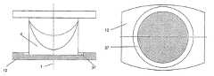
- FIG. 3is a perspective of an embodiment of the implant of the invention in the form of an intervertebral implant
- FIG. 4 ais a ventral view of an embodiment mode of the implant of the invention.
- FIG. 4 bis a lateral view of the embodiment mode of the implant of the invention of FIG. 4 a
- FIG. 5is a view of a further embodiment mode of the implant of the invention having an articulating part mounted on the cover plate and rotatable about the central axis,
- FIG. 6 ais a view of another embodiment mode of the implant of the invention having an articulating part displaceable in a plane vertical to the central axis,
- FIG. 6 bis a section of the embodiment mode of the implant of the invention shown in FIG. 6 a,
- FIG. 7 ais a view of a further embodiment mode of the implant of the invention having an articulating part displaceable perpendicularly to the central axis, and
- FIG. 7 bis a section of the embodiment mode of the implant of the invention shown in FIG. 7 a.
- FIGS. 1 a through 1 dshow an embodiment of the implant of the invention comprising a first and a second articulating joint 4 ; 5 , FIG. 1 b showing the two articulating parts 4 ; 5 in sideview A.
- the first articulating part 4comprises a first central axis 1 and a first slide surface 6 intersecting said first central axis 1 .
- Said first slide surface 6is saddle-shaped and has a first saddle point 8 .
- the second articulating part 5has a second central axis 26 and a second slide surface 7 intersecting this second central axis 26 .
- the second slide surface 7also is saddle-shaped and includes the saddle point 9 .
- the articulating parts 4 ; 5comprise outermost ends 14 ; 15 which may be made to rest against the end surfaces of bones adjoining the articulating parts, in particular adjoining vertebras.
- the projections of the axes of rotation 10 ; 11intersect in a plane orthogonal to the central axis 1 at an angle of 90°.
- the minimal distance Ais vertical to the two axes of rotation 10 ; 11 .
- the second articulating part 5has been rotated about the first axes of rotation 10 ( FIG. 1 b ).
- the second saddle point 9is displaced during the rotation of the second articulating part 5 by the angle ⁇ along an arc of circle of radius R 1 and concentric with the first axis of rotation 10 .
- FIGS. 1 c and 1 dshow the articulating parts 4 ; 5 of the embodiment shown in FIGS. 1 a and 1 b , the second articulating part 5 having been rotated about the second axis of rotation 11 ( FIG. 1 c ) by the angle ⁇ .
- the second saddle point 9is displaced along an arc of circle having a radius R 2 concentric with the second axis of rotation 11 .
- FIG. 2shows the first articulating part 4 having a saddle-shaped slide surface 6 .
- the two axes of rotation 10 ; 11are shown in the rest condition of the implant of the invention at corresponding body erectness, that is the central axis 1 of the first articulating part 4 coincides with the central axis 26 of the second articulating part 5 ( FIG. 1 ).
- the axes of rotation 10 ; 11are perpendicular to the central axis 1 and lie in the planes 22 ; 23 .
- the first axis of rotation 10runs perpendicularly to a first plane 22 which is defined by the central axis 1 and the second axis of rotation 11 .
- the second axis of rotation 11runs perpendicularly to a second plane 23 itself perpendicular to the first plane 22 and defined by the central axis 1 and the first axis of rotation 10 .
- the first saddle point 8 of the first slide surface 6is situated both on the central axis 1 and on two arcs or circle 24 ; 25 of which the center in the rest position of the articulating parts 4 ; 5 is defined by the intersection of the central axis 1 with each of the axes of rotation 10 ; 11 .
- the first slide surface 6on one hand tightly follows the first arc of circle 24 concentric with the first axis of rotation 10 and on the other hand also the second arc of circle 25 concentric with the axis of rotation 11 .
- the radii R 1 of the first arc of circle 24 and R 2 of the second arc of circle 25are equal when the slide surfaces 7 ; 8 are congruent and correspond to half the distance A between the two axes of rotation 10 ; 11 .
- the slide surfaceis designed in a manner to be the complementary shape of a patch of a toroidal surface.
- FIG. 3shows an embodiment of the implant of the invention in the form of an intervertebral implant.
- the two articulating joints 4 ; 5comprise a connection site 2 ; 3 for each cover plate 12 ; 13 having surfaces 16 ; 17 that are axially outermost along the central axes 1 ; 26 and that are configured transversely to the central axes 1 ; 26 , said surfaces 16 ; 17 being movable to rest against the vertebras' end surfaces.
- the cover plates 12 ; 13each comprise two lateral edge surfaces 27 , one anterior edge surface 28 and one posterior edge surface 29 , the lateral edge surfaces 27 being substantially parallel to the first axis of rotation 10 .
- Both the anterior and the posterior edge surfaces 28 ; 29are configured substantially parallel to the second axis of rotation 11 .
- the implantis configured between the (omitted) adjoining vertebras in a manner that rotating the articulating parts 4 ; 5 about the first axis of rotation 10 allows laterally bending the vertebras connected to the implant, whereas rotating the articulating parts 4 ; 5 about the second axis of rotation 11 allows bending, respectively stretching the vertebras connected to the implant.
- the first cover plate 12is rigidly joined to the first articulating part 4 whereas the second cover plate 13 comprises a guide 20 in the form of a channel which runs perpendicularly to the central axis 26 and substantially parallel to the lateral edge surfaces 27 , as a result of which the second articulating part 5 together with its outermost end 15 designed to be complementary to the guide 20 can be inserted into this guide.
- serrations/fins 19are present at the outermost surfaces 16 ; 17 of the cover plates 12 ; 13 to provide the primary implant stabilization at the adjoining vertebras.
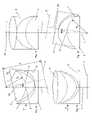
- FIGS. 4 a and 4 bdiffers from the embodiment of the implant of the invention shown in FIG. 3 only in that it is devoid of the serrations/fins 19 and in that the articulating parts 4 ; 5 are rotatable only within limited angles of rotation ⁇ and ⁇ about the axes of rotation 10 ; 11 .
- FIG. 4 ashows the implant ventrally, that is parallel to the axis of rotation 10
- FIG. 4 bshows the implant laterally, that is parallel to the axis of rotation 11 ( FIG. 4 b ).
- the limitation of the angles of rotation ⁇ and ⁇is determined by selecting the sizes H L ; H A ; H P ; R 1 ; R 2 ; h 1 and h 2 at the articulating parts 4 ; 5 , where when the maximum angles of rotation ⁇ or ⁇ are reached, the particular ends 32 ; 33 ; 34 —of the articulating parts 4 ; 5 —pointing toward the other articulating part 4 ; 5 will rest on the inner surfaces 30 ; 31 of the cover plate 12 ; 13 opposite the articulating part 4 ; 5 , and:
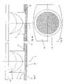
- FIG. 5shows an embodiment of the implant of the invention differing from the embodiments shown in FIGS. 1 through 4 in that the outermost end 14 of the first articulating part 4 is received in a complementary recess 37 in the cover plate 12 coaxial with the central axis as a result of which the first articulating part 4 may be rotated about the central axis 1 to be assembled to the cover plate 12 .
- FIGS. 6 a and 6 bshow an embodiment of the implant of the invention which differs from the embodiment shown in FIG. 5 only in that the recess 37 exhibits a larger diameter toward the central axis 1 than the outermost end 14 of the first articulating part 4 , as a result of which the first articulating part 4 is displaceable relative to the cover plate 12 in a plane that is perpendicular to the central axis 1 .
- FIGS. 7 a and 7 bshow an embodiment of the implant of the invention which differs from the embodiment shown in FIG. 5 only in that the recess 37 is oval parallelly to a displacement axis 40 which is perpendicular to the central axis 1 and comprises a cavity 39 whereas the outermost end 14 of the first articulating part 4 terminally comprises a widening 38 coaxial with the central axis 1 entering said cavity 39 , as result of which the first articulating part 4 on one hand is displaceable parallel to the displacement axis 40 and on the other hand is axially secured in position relative to the central axis 1 by the widening 38 engaging the cavity 39 .
Landscapes
- Health & Medical Sciences (AREA)
- Engineering & Computer Science (AREA)
- Biomedical Technology (AREA)
- Neurology (AREA)
- Orthopedic Medicine & Surgery (AREA)
- Cardiology (AREA)
- Oral & Maxillofacial Surgery (AREA)
- Transplantation (AREA)
- Heart & Thoracic Surgery (AREA)
- Vascular Medicine (AREA)
- Life Sciences & Earth Sciences (AREA)
- Animal Behavior & Ethology (AREA)
- General Health & Medical Sciences (AREA)
- Public Health (AREA)
- Veterinary Medicine (AREA)
- Prostheses (AREA)
- Materials For Medical Uses (AREA)
Abstract
Description
- the position of the center of rotation during bending or stretching and/or when laterally bending the vertebras is better matched to physiology,
- the slide surfaces can be displaced relative to and on each other in the absence of substantial friction, and forces and torques are minimized as much as possible by reproducing the corresponding lever arms, and
- twisting motions about the spinal column's longitudinal axis may be opposed by bracing.
- known performance-tested combinations of joint replacement materials such as highly crosslinked polyethylene (UHMWPE [ultra-high molecular weight polyethylene]) and a cobalt/chromium alloy may be used,
- low friction when the slide surfaces are moved relative to each other can be attained, and
- the rotations of the articulating parts about the central axes can be damped.
- HLis the height between the
first saddle point 8 and the inner ends32 of the first articulating joint4 that point toward the second articulating joint5; - HAis the height between the
second saddle point 9 and theanterior end 34 of the articulatingpart 5 pointing toward the first articulatingpart 4; - HPis the height between the
saddle point 9 and theposterior end 33 of the second articulatingpart 5 pointing toward the first articulatingpart 4; - R1is the radius of the
first slide surface 6 in the first plane22 (FIG. 2 ) perpendicular to the first axis ofrotation 10 and containing thefirst saddle point 8; - R2is the radius of the second slide surface in the second plane23 (
FIG. 2 ) perpendicular to the second axis ofrotation 11 and containing thesecond saddle point 9; - h1is the height between the
first saddle point 8 and theinner surface 31 of thefirst cover plate 12; and - h2is the height between the
second saddle point 9 and theinner surface 30 of thesecond cover plate 13.
- HLis the height between the
Claims (15)
Priority Applications (1)
| Application Number | Priority Date | Filing Date | Title |
|---|---|---|---|
| US12/425,005US8092540B2 (en) | 2002-09-18 | 2009-04-16 | Implant comprising a two-piece joint |
Applications Claiming Priority (1)
| Application Number | Priority Date | Filing Date | Title |
|---|---|---|---|
| PCT/CH2002/000512WO2004026186A1 (en) | 2002-09-18 | 2002-09-18 | Implant comprising a two-piece joint |
Related Child Applications (1)
| Application Number | Title | Priority Date | Filing Date |
|---|---|---|---|
| US12/425,005ContinuationUS8092540B2 (en) | 2002-09-18 | 2009-04-16 | Implant comprising a two-piece joint |
Publications (2)
| Publication Number | Publication Date |
|---|---|
| US20050256577A1 US20050256577A1 (en) | 2005-11-17 |
| US7537614B2true US7537614B2 (en) | 2009-05-26 |
Family
ID=32000096
Family Applications (2)
| Application Number | Title | Priority Date | Filing Date |
|---|---|---|---|
| US10/528,081Expired - LifetimeUS7537614B2 (en) | 2002-09-18 | 2002-09-18 | Implant comprising a two-piece joint |
| US12/425,005Expired - Fee RelatedUS8092540B2 (en) | 2002-09-18 | 2009-04-16 | Implant comprising a two-piece joint |
Family Applications After (1)
| Application Number | Title | Priority Date | Filing Date |
|---|---|---|---|
| US12/425,005Expired - Fee RelatedUS8092540B2 (en) | 2002-09-18 | 2009-04-16 | Implant comprising a two-piece joint |
Country Status (10)
| Country | Link |
|---|---|
| US (2) | US7537614B2 (en) |
| EP (1) | EP1539051B1 (en) |
| JP (1) | JP4210648B2 (en) |
| CN (1) | CN100427045C (en) |
| AT (1) | ATE394083T1 (en) |
| AU (1) | AU2002322984B2 (en) |
| CA (1) | CA2497623C (en) |
| DE (1) | DE50212245D1 (en) |
| ES (1) | ES2306774T3 (en) |
| WO (1) | WO2004026186A1 (en) |
Cited By (10)
| Publication number | Priority date | Publication date | Assignee | Title |
|---|---|---|---|---|
| US20050033435A1 (en)* | 2003-08-04 | 2005-02-10 | Spine Next | Intervertebral disk prosthesis |
| US20050240272A1 (en)* | 2003-03-06 | 2005-10-27 | Spinecore, Inc. | Cervical disc replacement |
| US20090204217A1 (en)* | 2002-09-18 | 2009-08-13 | Daniel Baumgartner | Implant comprising a two-piece joint |
| US20100100186A1 (en)* | 2003-03-06 | 2010-04-22 | Spinecore, Inc. | Instrumentation and methods for use in implanting a cervical disc replacement device |
| US20100256758A1 (en)* | 2009-04-02 | 2010-10-07 | Synvasive Technology, Inc. | Monolithic orthopedic implant with an articular finished surface |
| US20100268337A1 (en)* | 2009-04-02 | 2010-10-21 | Synvasive Technology, Inc. | Monolithic orthopedic implant with an articular finished surface |
| US8277507B2 (en) | 2002-04-12 | 2012-10-02 | Spinecore, Inc. | Spacerless artificial disc replacements |
| US8366772B2 (en) | 2002-04-23 | 2013-02-05 | Spinecore, Inc. | Artificial disc replacements with natural kinematics |
| US8470041B2 (en) | 2002-04-12 | 2013-06-25 | Spinecore, Inc. | Two-component artificial disc replacements |
| US9358122B2 (en) | 2011-01-07 | 2016-06-07 | K2M, Inc. | Interbody spacer |
Families Citing this family (26)
| Publication number | Priority date | Publication date | Assignee | Title |
|---|---|---|---|---|
| US7494507B2 (en) | 2000-01-30 | 2009-02-24 | Diamicron, Inc. | Articulating diamond-surfaced spinal implants |
| US6673113B2 (en) | 2001-10-18 | 2004-01-06 | Spinecore, Inc. | Intervertebral spacer device having arch shaped spring elements |
| US7169182B2 (en) | 2001-07-16 | 2007-01-30 | Spinecore, Inc. | Implanting an artificial intervertebral disc |
| US7771477B2 (en) | 2001-10-01 | 2010-08-10 | Spinecore, Inc. | Intervertebral spacer device utilizing a belleville washer having radially spaced concentric grooves |
| US7713302B2 (en) | 2001-10-01 | 2010-05-11 | Spinecore, Inc. | Intervertebral spacer device utilizing a spirally slotted belleville washer having radially spaced concentric grooves |
| AU2003297195A1 (en)* | 2002-12-17 | 2004-07-22 | Amedica Corporation | Total disc implant |
| EP1610740A4 (en) | 2003-04-04 | 2009-04-08 | Theken Disc Llc | Artificial disc prosthesis |
| DE20310433U1 (en) | 2003-07-08 | 2003-09-04 | Aesculap AG & Co. KG, 78532 Tuttlingen | Surgical device for inserting dual component implant into appropriate space at spine, comprising particularly shaped holding area |
| DE10330698B4 (en) | 2003-07-08 | 2005-05-25 | Aesculap Ag & Co. Kg | Intervertebral implant |
| DE10339170B4 (en)* | 2003-08-22 | 2009-10-15 | Aesculap Ag | Intervertebral implant |
| US20050165487A1 (en) | 2004-01-28 | 2005-07-28 | Muhanna Nabil L. | Artificial intervertebral disc |
| DE202004009542U1 (en) | 2004-06-16 | 2004-08-12 | Aesculap Ag & Co. Kg | Artificial intervertebral disk, comprising core with intensely curved upper and less curved lower surface |
| US20060149372A1 (en)* | 2004-12-17 | 2006-07-06 | Paxson Robert D | Artificial spinal disc |
| US8777959B2 (en) | 2005-05-27 | 2014-07-15 | Spinecore, Inc. | Intervertebral disc and insertion methods therefor |
| US8137404B2 (en) | 2006-03-28 | 2012-03-20 | Depuy Spine, Inc. | Artificial disc replacement using posterior approach |
| US8282641B2 (en) | 2006-03-28 | 2012-10-09 | Depuy Spine, Inc. | Methods and instrumentation for disc replacement |
| US8043379B2 (en) | 2006-04-21 | 2011-10-25 | Depuy Spine, Inc. | Disc prosthesis having remote flexion/extension center of rotation |
| US8715352B2 (en) | 2006-12-14 | 2014-05-06 | Depuy Spine, Inc. | Buckling disc replacement |
| WO2008098228A2 (en) | 2007-02-09 | 2008-08-14 | Diamicron, Inc. | Multi-lobe artificial spine joint |
| AU2009205679B2 (en) | 2008-01-18 | 2013-12-05 | Spinecore, Inc. | Instruments and methods for inserting artificial intervertebral implants |
| US8403988B2 (en) | 2009-09-11 | 2013-03-26 | Depuy Spine, Inc. | Minimally invasive intervertebral staple distraction devices |
| US9615933B2 (en)* | 2009-09-15 | 2017-04-11 | DePuy Synthes Products, Inc. | Expandable ring intervertebral fusion device |
| JP6629833B2 (en)* | 2014-07-19 | 2020-01-15 | ミュールバウアー マンフレート | Disc implant |
| US11452618B2 (en) | 2019-09-23 | 2022-09-27 | Dimicron, Inc | Spinal artificial disc removal tool |
| US11642226B2 (en) | 2020-05-01 | 2023-05-09 | Ensemble Orthopedics, Inc. | Implantable interpositional orthopedic pain management |
| US12290443B2 (en) | 2020-05-01 | 2025-05-06 | Ensemble Orthopedics, Inc. | Implantable interpositional orthopedic pain management |
Citations (30)
| Publication number | Priority date | Publication date | Assignee | Title |
|---|---|---|---|---|
| US5314477A (en)* | 1990-03-07 | 1994-05-24 | J.B.S. Limited Company | Prosthesis for intervertebral discs and instruments for implanting it |
| US5405400A (en)* | 1993-10-05 | 1995-04-11 | Orthomet, Inc. | Joint prosthesis enabling rotary circumduction |
| US5895428A (en)* | 1996-11-01 | 1999-04-20 | Berry; Don | Load bearing spinal joint implant |
| US5989291A (en)* | 1998-02-26 | 1999-11-23 | Third Millennium Engineering, Llc | Intervertebral spacer device |
| US6039763A (en)* | 1998-10-27 | 2000-03-21 | Disc Replacement Technologies, Inc. | Articulating spinal disc prosthesis |
| US6106557A (en)* | 1998-07-23 | 2000-08-22 | Howmedica Gmbh | Reconstruction system for vertebra |
| CA2391330A1 (en) | 1999-07-02 | 2001-01-11 | Spine Solutions Inc. | Intervertebral implant |
| US6290726B1 (en)* | 2000-01-30 | 2001-09-18 | Diamicron, Inc. | Prosthetic hip joint having sintered polycrystalline diamond compact articulation surfaces |
| US6296664B1 (en)* | 1998-06-17 | 2001-10-02 | Surgical Dynamics, Inc. | Artificial intervertebral disc |
| US6368350B1 (en)* | 1999-03-11 | 2002-04-09 | Sulzer Spine-Tech Inc. | Intervertebral disc prosthesis and method |
| US20020111684A1 (en)* | 2001-02-15 | 2002-08-15 | Ralph James D. | Intervertebral spacer device utilizing a belleville washer having radially spaced concentric grooves |
| US20020111686A1 (en)* | 2001-02-15 | 2002-08-15 | Ralph James D. | Intervertebral spacer device utilizing a spirally slotted belleville washer and a rotational mounting |
| US6517580B1 (en)* | 2000-03-03 | 2003-02-11 | Scient'x Societe A Responsabilite Limited | Disk prosthesis for cervical vertebrae |
| US6540785B1 (en)* | 1998-10-22 | 2003-04-01 | Sdgi Holdings, Inc. | Artificial intervertebral joint permitting translational and rotational motion |
| US20030069586A1 (en)* | 2001-07-16 | 2003-04-10 | Errico Joseph P. | Instrumentation and methods for use in implanting an artificial intervertebral disc |
| US20030078666A1 (en)* | 2001-10-18 | 2003-04-24 | Ralph James D. | Intervertebral spacer device having a slotted partial circular domed arch strip spring |
| US6610093B1 (en)* | 2000-07-28 | 2003-08-26 | Perumala Corporation | Method and apparatus for stabilizing adjacent vertebrae |
| US20030191534A1 (en)* | 2000-03-10 | 2003-10-09 | Guy Viart | Intervertebral disc prosthesis |
| US20030199981A1 (en)* | 2002-04-23 | 2003-10-23 | Ferree Bret A. | Artificial disc replacements with natural kinematics |
| US20030204261A1 (en)* | 2002-04-25 | 2003-10-30 | Lukas Eisermann | Articular disc prosthesis and method for implanting the same |
| US20030208273A1 (en)* | 2002-01-09 | 2003-11-06 | Lukas Eisermann | Intervertebral prosthetic joint |
| US20030233146A1 (en)* | 2002-06-18 | 2003-12-18 | Alexander Grinberg | Intervertebral disc |
| US20040010316A1 (en)* | 2002-03-30 | 2004-01-15 | Lytton William | Intervertebral device and method of use |
| US6679915B1 (en)* | 1998-04-23 | 2004-01-20 | Sdgi Holdings, Inc. | Articulating spinal implant |
| US6682561B2 (en)* | 1998-06-18 | 2004-01-27 | Pioneer Laboratories, Inc. | Spinal fixation system |
| US6685742B1 (en)* | 2002-11-12 | 2004-02-03 | Roger P. Jackson | Articulated anterior expandable spinal fusion cage system |
| US20040024462A1 (en)* | 2002-04-12 | 2004-02-05 | Ferree Bret A. | Spacerless artificial disc replacements |
| US20040117022A1 (en)* | 2002-12-13 | 2004-06-17 | Theirry Marnay | Intervertebral implant, insertion tool and method of inserting same |
| US20040153157A1 (en)* | 2001-04-05 | 2004-08-05 | Arnold Keller | System for intervertebral disk prostheses |
| US7160327B2 (en)* | 2001-07-16 | 2007-01-09 | Spinecore, Inc. | Axially compressible artificial intervertebral disc having limited rotation using a captured ball and socket joint with a solid ball and compression locking post |
Family Cites Families (4)
| Publication number | Priority date | Publication date | Assignee | Title |
|---|---|---|---|---|
| US5645605A (en)* | 1995-09-18 | 1997-07-08 | Ascension Orthopedics, Inc. | Implant device to replace the carpometacarpal joint of the human thumb |
| US5702465A (en)* | 1996-05-13 | 1997-12-30 | Sulzer Orthopedics Inc. | Patella prosthesis having rotational and translational freedom |
| US6620196B1 (en)* | 2000-08-30 | 2003-09-16 | Sdgi Holdings, Inc. | Intervertebral disc nucleus implants and methods |
| US7537614B2 (en)* | 2002-09-18 | 2009-05-26 | Synthes Usa, Llc | Implant comprising a two-piece joint |
- 2002
- 2002-09-18USUS10/528,081patent/US7537614B2/ennot_activeExpired - Lifetime
- 2002-09-18JPJP2004536748Apatent/JP4210648B2/ennot_activeExpired - Lifetime
- 2002-09-18EPEP02754125Apatent/EP1539051B1/ennot_activeExpired - Lifetime
- 2002-09-18CNCNB028296060Apatent/CN100427045C/ennot_activeExpired - Fee Related
- 2002-09-18AUAU2002322984Apatent/AU2002322984B2/ennot_activeCeased
- 2002-09-18WOPCT/CH2002/000512patent/WO2004026186A1/enactiveIP Right Grant
- 2002-09-18ATAT02754125Tpatent/ATE394083T1/ennot_activeIP Right Cessation
- 2002-09-18ESES02754125Tpatent/ES2306774T3/ennot_activeExpired - Lifetime
- 2002-09-18CACA2497623Apatent/CA2497623C/ennot_activeExpired - Fee Related
- 2002-09-18DEDE50212245Tpatent/DE50212245D1/ennot_activeExpired - Lifetime
- 2009
- 2009-04-16USUS12/425,005patent/US8092540B2/ennot_activeExpired - Fee Related
Patent Citations (36)
| Publication number | Priority date | Publication date | Assignee | Title |
|---|---|---|---|---|
| US5314477A (en)* | 1990-03-07 | 1994-05-24 | J.B.S. Limited Company | Prosthesis for intervertebral discs and instruments for implanting it |
| US5405400A (en)* | 1993-10-05 | 1995-04-11 | Orthomet, Inc. | Joint prosthesis enabling rotary circumduction |
| US5895428A (en)* | 1996-11-01 | 1999-04-20 | Berry; Don | Load bearing spinal joint implant |
| US5989291A (en)* | 1998-02-26 | 1999-11-23 | Third Millennium Engineering, Llc | Intervertebral spacer device |
| US6679915B1 (en)* | 1998-04-23 | 2004-01-20 | Sdgi Holdings, Inc. | Articulating spinal implant |
| US6296664B1 (en)* | 1998-06-17 | 2001-10-02 | Surgical Dynamics, Inc. | Artificial intervertebral disc |
| US6656224B2 (en)* | 1998-06-17 | 2003-12-02 | Howmedica Osteonics Corp. | Artificial intervertebral disc |
| US20010051829A1 (en)* | 1998-06-17 | 2001-12-13 | Middleton Lance M. | Artificial intervertebral disc |
| US6682561B2 (en)* | 1998-06-18 | 2004-01-27 | Pioneer Laboratories, Inc. | Spinal fixation system |
| US6106557A (en)* | 1998-07-23 | 2000-08-22 | Howmedica Gmbh | Reconstruction system for vertebra |
| US6540785B1 (en)* | 1998-10-22 | 2003-04-01 | Sdgi Holdings, Inc. | Artificial intervertebral joint permitting translational and rotational motion |
| US6039763A (en)* | 1998-10-27 | 2000-03-21 | Disc Replacement Technologies, Inc. | Articulating spinal disc prosthesis |
| US6368350B1 (en)* | 1999-03-11 | 2002-04-09 | Sulzer Spine-Tech Inc. | Intervertebral disc prosthesis and method |
| CA2391330A1 (en) | 1999-07-02 | 2001-01-11 | Spine Solutions Inc. | Intervertebral implant |
| US6936071B1 (en)* | 1999-07-02 | 2005-08-30 | Spine Solutions, Inc. | Intervertebral implant |
| US6290726B1 (en)* | 2000-01-30 | 2001-09-18 | Diamicron, Inc. | Prosthetic hip joint having sintered polycrystalline diamond compact articulation surfaces |
| US6517580B1 (en)* | 2000-03-03 | 2003-02-11 | Scient'x Societe A Responsabilite Limited | Disk prosthesis for cervical vertebrae |
| US20030191534A1 (en)* | 2000-03-10 | 2003-10-09 | Guy Viart | Intervertebral disc prosthesis |
| US6682562B2 (en)* | 2000-03-10 | 2004-01-27 | Eurosurgical Sa | Intervertebral disc prosthesis |
| US6610093B1 (en)* | 2000-07-28 | 2003-08-26 | Perumala Corporation | Method and apparatus for stabilizing adjacent vertebrae |
| US20020111686A1 (en)* | 2001-02-15 | 2002-08-15 | Ralph James D. | Intervertebral spacer device utilizing a spirally slotted belleville washer and a rotational mounting |
| US20020111684A1 (en)* | 2001-02-15 | 2002-08-15 | Ralph James D. | Intervertebral spacer device utilizing a belleville washer having radially spaced concentric grooves |
| US20040153157A1 (en)* | 2001-04-05 | 2004-08-05 | Arnold Keller | System for intervertebral disk prostheses |
| US20030069586A1 (en)* | 2001-07-16 | 2003-04-10 | Errico Joseph P. | Instrumentation and methods for use in implanting an artificial intervertebral disc |
| US7160327B2 (en)* | 2001-07-16 | 2007-01-09 | Spinecore, Inc. | Axially compressible artificial intervertebral disc having limited rotation using a captured ball and socket joint with a solid ball and compression locking post |
| US20030078666A1 (en)* | 2001-10-18 | 2003-04-24 | Ralph James D. | Intervertebral spacer device having a slotted partial circular domed arch strip spring |
| US20030208273A1 (en)* | 2002-01-09 | 2003-11-06 | Lukas Eisermann | Intervertebral prosthetic joint |
| US20040010316A1 (en)* | 2002-03-30 | 2004-01-15 | Lytton William | Intervertebral device and method of use |
| US20040024462A1 (en)* | 2002-04-12 | 2004-02-05 | Ferree Bret A. | Spacerless artificial disc replacements |
| US6706068B2 (en)* | 2002-04-23 | 2004-03-16 | Bret A. Ferree | Artificial disc replacements with natural kinematics |
| US20030199981A1 (en)* | 2002-04-23 | 2003-10-23 | Ferree Bret A. | Artificial disc replacements with natural kinematics |
| US20030204261A1 (en)* | 2002-04-25 | 2003-10-30 | Lukas Eisermann | Articular disc prosthesis and method for implanting the same |
| US20030233146A1 (en)* | 2002-06-18 | 2003-12-18 | Alexander Grinberg | Intervertebral disc |
| US6685742B1 (en)* | 2002-11-12 | 2004-02-03 | Roger P. Jackson | Articulated anterior expandable spinal fusion cage system |
| US20040117022A1 (en)* | 2002-12-13 | 2004-06-17 | Theirry Marnay | Intervertebral implant, insertion tool and method of inserting same |
| US7204852B2 (en)* | 2002-12-13 | 2007-04-17 | Spine Solutions, Inc. | Intervertebral implant, insertion tool and method of inserting same |
Cited By (40)
| Publication number | Priority date | Publication date | Assignee | Title |
|---|---|---|---|---|
| US10786363B2 (en) | 2002-04-12 | 2020-09-29 | Spinecore, Inc. | Spacerless artificial disc replacements |
| US8679182B2 (en) | 2002-04-12 | 2014-03-25 | Spinecore, Inc. | Spacerless artificial disc replacements |
| US8801789B2 (en) | 2002-04-12 | 2014-08-12 | Spinecore, Inc. | Two-component artificial disc replacements |
| US10271956B2 (en) | 2002-04-12 | 2019-04-30 | Spinecore, Inc. | Spacerless artificial disc replacements |
| US8470041B2 (en) | 2002-04-12 | 2013-06-25 | Spinecore, Inc. | Two-component artificial disc replacements |
| US9198773B2 (en) | 2002-04-12 | 2015-12-01 | Spinecore, Inc. | Spacerless artificial disc replacements |
| US8277507B2 (en) | 2002-04-12 | 2012-10-02 | Spinecore, Inc. | Spacerless artificial disc replacements |
| US9572679B2 (en) | 2002-04-23 | 2017-02-21 | Spinecore, Inc. | Artificial disc replacements with natural kinematics |
| US9877841B2 (en) | 2002-04-23 | 2018-01-30 | Spinecore, Inc. | Artificial disc replacements with natural kinematics |
| US8366772B2 (en) | 2002-04-23 | 2013-02-05 | Spinecore, Inc. | Artificial disc replacements with natural kinematics |
| US9168146B2 (en) | 2002-04-23 | 2015-10-27 | Spinecore, Inc. | Artificial disc replacements with natural kinematics |
| US8784492B2 (en) | 2002-04-23 | 2014-07-22 | Spinecore, Inc. | Artificial disc replacements with natural kinematics |
| US10299933B2 (en) | 2002-04-23 | 2019-05-28 | Spinecore, Inc. | Artificial disc replacements with natural kinematics |
| US20090204217A1 (en)* | 2002-09-18 | 2009-08-13 | Daniel Baumgartner | Implant comprising a two-piece joint |
| US8092540B2 (en)* | 2002-09-18 | 2012-01-10 | Synthes Usa, Llc | Implant comprising a two-piece joint |
| US11382762B2 (en) | 2003-03-06 | 2022-07-12 | Howmedica Osteonics Corp. | Instrumentation and methods for use in implanting a cervical disc replacement device |
| US9603716B2 (en) | 2003-03-06 | 2017-03-28 | Spinecore, Inc. | Intervertebral disc replacement |
| US10369005B2 (en) | 2003-03-06 | 2019-08-06 | Spinecore, Inc. | Cervical disc replacement |
| US8435297B2 (en) | 2003-03-06 | 2013-05-07 | Spinecore, Inc. | Intervertebral disc replacement |
| US20100070040A1 (en)* | 2003-03-06 | 2010-03-18 | Spinecore, Inc. | Intervertebral Disc Replacement |
| US10835385B2 (en) | 2003-03-06 | 2020-11-17 | Howmedica Osteonics Corp. | Instrumentation and methods for use in implanting a cervical disc replacement device |
| US20050240272A1 (en)* | 2003-03-06 | 2005-10-27 | Spinecore, Inc. | Cervical disc replacement |
| US8109979B2 (en) | 2003-03-06 | 2012-02-07 | Spinecore, Inc. | Instrumentation and methods for use in implanting a cervical disc replacement device |
| US10159578B2 (en) | 2003-03-06 | 2018-12-25 | Spinecore, Inc. | Instrumentation and methods for use in implanting a cervical disc replacement device |
| US8936640B2 (en) | 2003-03-06 | 2015-01-20 | Spinecore, Inc. | Cervical disc replacement |
| US8961608B2 (en) | 2003-03-06 | 2015-02-24 | Spinecore, Inc. | Intervertebral disc replacement |
| US9028552B2 (en)* | 2003-03-06 | 2015-05-12 | Spinecore, Inc. | Cervical disc replacement |
| US20100076506A1 (en)* | 2003-03-06 | 2010-03-25 | Spinecore, Inc. | Instrumentation and methods for use in implanting a cervical disc replacement device |
| US8231628B2 (en) | 2003-03-06 | 2012-07-31 | Spinecore, Inc. | Instrumentation and methods for use in implanting a cervical disc replacement device |
| US20100100186A1 (en)* | 2003-03-06 | 2010-04-22 | Spinecore, Inc. | Instrumentation and methods for use in implanting a cervical disc replacement device |
| US20100087870A1 (en)* | 2003-03-06 | 2010-04-08 | Spinecore, Inc. | Instrumentation and methods for use in implanting a cervical disc replacement device |
| US20100121454A1 (en)* | 2003-08-04 | 2010-05-13 | Zimmer Spine S.A.S. | Method of implanting intervertebral disk prosthesis |
| US20050033435A1 (en)* | 2003-08-04 | 2005-02-10 | Spine Next | Intervertebral disk prosthesis |
| US7896919B2 (en) | 2003-08-04 | 2011-03-01 | Zimmer Spine S.A.S. | Method of implanting intervertebral disk prosthesis |
| US7611538B2 (en)* | 2003-08-04 | 2009-11-03 | Zimmer Spine S.A.S. | Intervertebral disk prosthesis |
| US8226721B2 (en) | 2003-08-04 | 2012-07-24 | Zimmer Spine S.A.S. | Method of implanting intervertebral disk prosthesis |
| US20100268337A1 (en)* | 2009-04-02 | 2010-10-21 | Synvasive Technology, Inc. | Monolithic orthopedic implant with an articular finished surface |
| US8556972B2 (en) | 2009-04-02 | 2013-10-15 | Sevika Holding AG | Monolithic orthopedic implant with an articular finished surface |
| US20100256758A1 (en)* | 2009-04-02 | 2010-10-07 | Synvasive Technology, Inc. | Monolithic orthopedic implant with an articular finished surface |
| US9358122B2 (en) | 2011-01-07 | 2016-06-07 | K2M, Inc. | Interbody spacer |
Also Published As
| Publication number | Publication date |
|---|---|
| US20050256577A1 (en) | 2005-11-17 |
| AU2002322984A1 (en) | 2004-04-08 |
| ES2306774T3 (en) | 2008-11-16 |
| EP1539051B1 (en) | 2008-05-07 |
| JP4210648B2 (en) | 2009-01-21 |
| US20090204217A1 (en) | 2009-08-13 |
| DE50212245D1 (en) | 2008-06-19 |
| AU2002322984B2 (en) | 2006-06-22 |
| CA2497623A1 (en) | 2004-04-01 |
| US8092540B2 (en) | 2012-01-10 |
| JP2005538783A (en) | 2005-12-22 |
| EP1539051A1 (en) | 2005-06-15 |
| CN1668258A (en) | 2005-09-14 |
| CN100427045C (en) | 2008-10-22 |
| ATE394083T1 (en) | 2008-05-15 |
| CA2497623C (en) | 2011-05-17 |
| WO2004026186A1 (en) | 2004-04-01 |
Similar Documents
| Publication | Publication Date | Title |
|---|---|---|
| US7537614B2 (en) | Implant comprising a two-piece joint | |
| US7637955B2 (en) | Constrained artificial spinal disc | |
| US20050216092A1 (en) | Constrained artificial implant for orthopaedic applications | |
| AU750180B2 (en) | Articulating spinal disc prosthesis | |
| US7887589B2 (en) | Minimally invasive spinal disc stabilizer and insertion tool | |
| US7597713B2 (en) | Intervertebral implant comprising a three-part articulation | |
| US8231676B2 (en) | Motion preserving artificial intervertebral disc device | |
| CA2518068C (en) | Cervical disc replacement | |
| US7708760B2 (en) | Tri-joint implant | |
| US20040030391A1 (en) | Artificial intervertebral disc spacers | |
| JP2008509792A (en) | Intervertebral disc system | |
| KR20070098801A (en) | Intervertebral prosthesis | |
| NZ540268A (en) | Intervertebral implant | |
| JP2006509560A (en) | Intervertebral implant having joint parts mounted on rolling elements | |
| US20120109315A1 (en) | Total disc replacement device | |
| KR20050109459A (en) | Intervertebral implant comprising joint parts that are mounted to form a universal joint | |
| NZ555344A (en) | A modular intervertebral implant that articulates using nesting spherical surfaces that is constructed from a kit of parts to have a selectable centre of rotation position | |
| KR100881436B1 (en) | Implant consisting of two connecting pieces |
Legal Events
| Date | Code | Title | Description |
|---|---|---|---|
| AS | Assignment | Owner name:MATHYS MEDIZINALTECHNIK AG, SWITZERLAND Free format text:ASSIGNMENT OF ASSIGNORS INTEREST;ASSIGNORS:BAUMGARTNER, DANIEL;BURRI, ADRIAN;MATHIEU, CLAUDE;REEL/FRAME:015989/0226 Effective date:20050214 | |
| AS | Assignment | Owner name:SYNTHES GMBH, SWITZERLAND Free format text:ASSIGNMENT OF ASSIGNORS INTEREST;ASSIGNOR:MATHYS MEDIZINALTECHNIK AG;REEL/FRAME:017618/0118 Effective date:20060512 | |
| AS | Assignment | Owner name:SYNTHES (USA), PENNSYLVANIA Free format text:ASSIGNMENT OF ASSIGNORS INTEREST;ASSIGNOR:SYNTHES GMBH;REEL/FRAME:017797/0513 Effective date:20060609 | |
| AS | Assignment | Owner name:HFSC COMPANY, PENNSYLVANIA Free format text:ASSIGNMENT OF ASSIGNORS INTEREST;ASSIGNOR:SYNTHES (USA);REEL/FRAME:017920/0428 Effective date:20060623 | |
| AS | Assignment | Owner name:SYNTHES (USA), PENNSYLVANIA Free format text:ASSIGNMENT OF ASSIGNORS INTEREST;ASSIGNOR:HFSC COMPANY;REEL/FRAME:018249/0799 Effective date:20060914 | |
| FEPP | Fee payment procedure | Free format text:PAYOR NUMBER ASSIGNED (ORIGINAL EVENT CODE: ASPN); ENTITY STATUS OF PATENT OWNER: LARGE ENTITY | |
| STCF | Information on status: patent grant | Free format text:PATENTED CASE | |
| AS | Assignment | Owner name:SYNTHES USA, LLC, PENNSYLVANIA Free format text:CHANGE OF NAME;ASSIGNOR:SYNTHES (U.S.A.);REEL/FRAME:022826/0140 Effective date:20081223 Owner name:SYNTHES USA, LLC,PENNSYLVANIA Free format text:CHANGE OF NAME;ASSIGNOR:SYNTHES (U.S.A.);REEL/FRAME:022826/0140 Effective date:20081223 | |
| FPAY | Fee payment | Year of fee payment:4 | |
| FPAY | Fee payment | Year of fee payment:8 | |
| MAFP | Maintenance fee payment | Free format text:PAYMENT OF MAINTENANCE FEE, 12TH YEAR, LARGE ENTITY (ORIGINAL EVENT CODE: M1553); ENTITY STATUS OF PATENT OWNER: LARGE ENTITY Year of fee payment:12 |