US7537573B2 - Active muscle assistance and resistance device and method - Google Patents
Active muscle assistance and resistance device and methodDownload PDFInfo
- Publication number
- US7537573B2 US7537573B2US11/221,452US22145205AUS7537573B2US 7537573 B2US7537573 B2US 7537573B2US 22145205 AUS22145205 AUS 22145205AUS 7537573 B2US7537573 B2US 7537573B2
- Authority
- US
- United States
- Prior art keywords
- muscle
- user
- actuator
- joint
- stress
- Prior art date
- Legal status (The legal status is an assumption and is not a legal conclusion. Google has not performed a legal analysis and makes no representation as to the accuracy of the status listed.)
- Expired - Fee Related, expires
Links
- 210000003205muscleAnatomy0.000titleclaimsabstractdescription136
- 238000000034methodMethods0.000titleclaimsabstractdescription30
- 230000033001locomotionEffects0.000claimsabstractdescription67
- 238000012545processingMethods0.000claimsdescription7
- 230000003213activating effectEffects0.000claimsdescription4
- 238000005259measurementMethods0.000claimsdescription4
- 230000009194climbingEffects0.000claimsdescription3
- 230000003287optical effectEffects0.000claimsdescription2
- 230000008569processEffects0.000claimsdescription2
- 208000027418Wounds and injuryDiseases0.000abstractdescription3
- 230000006378damageEffects0.000abstractdescription3
- 208000014674injuryDiseases0.000abstractdescription3
- 230000002708enhancing effectEffects0.000abstractdescription2
- 210000003127kneeAnatomy0.000description33
- 210000002414legAnatomy0.000description20
- 230000035882stressEffects0.000description20
- 238000010586diagramMethods0.000description12
- 230000037230mobilityEffects0.000description11
- 210000002683footAnatomy0.000description9
- 238000012549trainingMethods0.000description9
- 230000008878couplingEffects0.000description7
- 238000010168coupling processMethods0.000description7
- 238000005859coupling reactionMethods0.000description7
- 230000006870functionEffects0.000description6
- 210000003141lower extremityAnatomy0.000description6
- 210000002303tibiaAnatomy0.000description6
- 210000001624hipAnatomy0.000description5
- 230000007246mechanismEffects0.000description5
- 230000008859changeEffects0.000description4
- 210000001699lower legAnatomy0.000description4
- 210000004417patellaAnatomy0.000description4
- XEEYBQQBJWHFJM-UHFFFAOYSA-NIronChemical compound[Fe]XEEYBQQBJWHFJM-UHFFFAOYSA-N0.000description3
- 210000003423ankleAnatomy0.000description3
- 230000003416augmentationEffects0.000description3
- 239000003623enhancerSubstances0.000description3
- 230000005484gravityEffects0.000description3
- 230000003183myoelectrical effectEffects0.000description3
- 229920000642polymerPolymers0.000description3
- 230000004044responseEffects0.000description3
- 210000000689upper legAnatomy0.000description3
- 230000004913activationEffects0.000description2
- 230000008901benefitEffects0.000description2
- 230000037396body weightEffects0.000description2
- 239000000872bufferSubstances0.000description2
- 239000003990capacitorSubstances0.000description2
- 239000004020conductorSubstances0.000description2
- 238000001514detection methodMethods0.000description2
- 239000003989dielectric materialSubstances0.000description2
- 230000000694effectsEffects0.000description2
- 230000005686electrostatic fieldEffects0.000description2
- 230000009881electrostatic interactionEffects0.000description2
- 210000003414extremityAnatomy0.000description2
- 230000005021gaitEffects0.000description2
- 239000011810insulating materialSubstances0.000description2
- 210000000629knee jointAnatomy0.000description2
- 239000000463materialSubstances0.000description2
- 210000003314quadriceps muscleAnatomy0.000description2
- 230000009467reductionEffects0.000description2
- 210000000707wristAnatomy0.000description2
- 229920000049Carbon (fiber)Polymers0.000description1
- RYGMFSIKBFXOCR-UHFFFAOYSA-NCopperChemical compound[Cu]RYGMFSIKBFXOCR-UHFFFAOYSA-N0.000description1
- 206010017577Gait disturbanceDiseases0.000description1
- 208000010428Muscle WeaknessDiseases0.000description1
- 206010028372Muscular weaknessDiseases0.000description1
- 241001272996Polyphylla fulloSpecies0.000description1
- XAGFODPZIPBFFR-UHFFFAOYSA-NaluminiumChemical compound[Al]XAGFODPZIPBFFR-UHFFFAOYSA-N0.000description1
- 229910052782aluminiumInorganic materials0.000description1
- 238000013459approachMethods0.000description1
- 238000005452bendingMethods0.000description1
- 230000002146bilateral effectEffects0.000description1
- 244000309466calfSpecies0.000description1
- 239000004917carbon fiberSubstances0.000description1
- 230000015556catabolic processEffects0.000description1
- 238000006243chemical reactionMethods0.000description1
- 238000004891communicationMethods0.000description1
- 230000006835compressionEffects0.000description1
- 238000007906compressionMethods0.000description1
- 230000008602contractionEffects0.000description1
- 229910052802copperInorganic materials0.000description1
- 239000010949copperSubstances0.000description1
- 230000007812deficiencyEffects0.000description1
- 238000013461designMethods0.000description1
- 230000009977dual effectEffects0.000description1
- 210000001513elbowAnatomy0.000description1
- 230000005611electricityEffects0.000description1
- 230000003203everyday effectEffects0.000description1
- 230000005284excitationEffects0.000description1
- 230000006355external stressEffects0.000description1
- 230000036541healthEffects0.000description1
- 230000001771impaired effectEffects0.000description1
- 229910052742ironInorganic materials0.000description1
- 230000003137locomotive effectEffects0.000description1
- 210000004705lumbosacral regionAnatomy0.000description1
- 239000000696magnetic materialSubstances0.000description1
- VNWKTOKETHGBQD-UHFFFAOYSA-NmethaneChemical compoundCVNWKTOKETHGBQD-UHFFFAOYSA-N0.000description1
- 238000012544monitoring processMethods0.000description1
- 230000004220muscle functionEffects0.000description1
- 201000006938muscular dystrophyDiseases0.000description1
- 239000002985plastic filmSubstances0.000description1
- 238000005381potential energyMethods0.000description1
- 230000000750progressive effectEffects0.000description1
- 238000011084recoveryMethods0.000description1
- 230000001172regenerating effectEffects0.000description1
- 230000008929regenerationEffects0.000description1
- 238000011069regeneration methodMethods0.000description1
- 230000000630rising effectEffects0.000description1
- 238000005070samplingMethods0.000description1
- 208000020431spinal cord injuryDiseases0.000description1
- 230000007103staminaEffects0.000description1
- 230000003068static effectEffects0.000description1
- 239000000758substrateSubstances0.000description1
- 239000013589supplementSubstances0.000description1
- 210000000115thoracic cavityAnatomy0.000description1
- 230000007704transitionEffects0.000description1
- 230000001960triggered effectEffects0.000description1
- 238000004804windingMethods0.000description1
Images


Classifications
- A—HUMAN NECESSITIES
- A61—MEDICAL OR VETERINARY SCIENCE; HYGIENE
- A61H—PHYSICAL THERAPY APPARATUS, e.g. DEVICES FOR LOCATING OR STIMULATING REFLEX POINTS IN THE BODY; ARTIFICIAL RESPIRATION; MASSAGE; BATHING DEVICES FOR SPECIAL THERAPEUTIC OR HYGIENIC PURPOSES OR SPECIFIC PARTS OF THE BODY
- A61H1/00—Apparatus for passive exercising; Vibrating apparatus; Chiropractic devices, e.g. body impacting devices, external devices for briefly extending or aligning unbroken bones
- A61H1/02—Stretching or bending or torsioning apparatus for exercising
- A61H1/0237—Stretching or bending or torsioning apparatus for exercising for the lower limbs
- A61H1/024—Knee
- A—HUMAN NECESSITIES
- A61—MEDICAL OR VETERINARY SCIENCE; HYGIENE
- A61H—PHYSICAL THERAPY APPARATUS, e.g. DEVICES FOR LOCATING OR STIMULATING REFLEX POINTS IN THE BODY; ARTIFICIAL RESPIRATION; MASSAGE; BATHING DEVICES FOR SPECIAL THERAPEUTIC OR HYGIENIC PURPOSES OR SPECIFIC PARTS OF THE BODY
- A61H1/00—Apparatus for passive exercising; Vibrating apparatus; Chiropractic devices, e.g. body impacting devices, external devices for briefly extending or aligning unbroken bones
- A61H1/02—Stretching or bending or torsioning apparatus for exercising
- A61H1/0274—Stretching or bending or torsioning apparatus for exercising for the upper limbs
- A—HUMAN NECESSITIES
- A61—MEDICAL OR VETERINARY SCIENCE; HYGIENE
- A61H—PHYSICAL THERAPY APPARATUS, e.g. DEVICES FOR LOCATING OR STIMULATING REFLEX POINTS IN THE BODY; ARTIFICIAL RESPIRATION; MASSAGE; BATHING DEVICES FOR SPECIAL THERAPEUTIC OR HYGIENIC PURPOSES OR SPECIFIC PARTS OF THE BODY
- A61H3/00—Appliances for aiding patients or disabled persons to walk about
- A61H3/008—Appliances for aiding patients or disabled persons to walk about using suspension devices for supporting the body in an upright walking or standing position, e.g. harnesses
- A—HUMAN NECESSITIES
- A61—MEDICAL OR VETERINARY SCIENCE; HYGIENE
- A61H—PHYSICAL THERAPY APPARATUS, e.g. DEVICES FOR LOCATING OR STIMULATING REFLEX POINTS IN THE BODY; ARTIFICIAL RESPIRATION; MASSAGE; BATHING DEVICES FOR SPECIAL THERAPEUTIC OR HYGIENIC PURPOSES OR SPECIFIC PARTS OF THE BODY
- A61H1/00—Apparatus for passive exercising; Vibrating apparatus; Chiropractic devices, e.g. body impacting devices, external devices for briefly extending or aligning unbroken bones
- A61H1/02—Stretching or bending or torsioning apparatus for exercising
- A61H1/0237—Stretching or bending or torsioning apparatus for exercising for the lower limbs
- A61H1/0244—Hip
- A—HUMAN NECESSITIES
- A61—MEDICAL OR VETERINARY SCIENCE; HYGIENE
- A61H—PHYSICAL THERAPY APPARATUS, e.g. DEVICES FOR LOCATING OR STIMULATING REFLEX POINTS IN THE BODY; ARTIFICIAL RESPIRATION; MASSAGE; BATHING DEVICES FOR SPECIAL THERAPEUTIC OR HYGIENIC PURPOSES OR SPECIFIC PARTS OF THE BODY
- A61H1/00—Apparatus for passive exercising; Vibrating apparatus; Chiropractic devices, e.g. body impacting devices, external devices for briefly extending or aligning unbroken bones
- A61H1/02—Stretching or bending or torsioning apparatus for exercising
- A61H1/0237—Stretching or bending or torsioning apparatus for exercising for the lower limbs
- A61H1/0266—Foot
- A—HUMAN NECESSITIES
- A61—MEDICAL OR VETERINARY SCIENCE; HYGIENE
- A61H—PHYSICAL THERAPY APPARATUS, e.g. DEVICES FOR LOCATING OR STIMULATING REFLEX POINTS IN THE BODY; ARTIFICIAL RESPIRATION; MASSAGE; BATHING DEVICES FOR SPECIAL THERAPEUTIC OR HYGIENIC PURPOSES OR SPECIFIC PARTS OF THE BODY
- A61H2201/00—Characteristics of apparatus not provided for in the preceding codes
- A61H2201/01—Constructive details
- A61H2201/0165—Damping, vibration related features
- A—HUMAN NECESSITIES
- A61—MEDICAL OR VETERINARY SCIENCE; HYGIENE
- A61H—PHYSICAL THERAPY APPARATUS, e.g. DEVICES FOR LOCATING OR STIMULATING REFLEX POINTS IN THE BODY; ARTIFICIAL RESPIRATION; MASSAGE; BATHING DEVICES FOR SPECIAL THERAPEUTIC OR HYGIENIC PURPOSES OR SPECIFIC PARTS OF THE BODY
- A61H2201/00—Characteristics of apparatus not provided for in the preceding codes
- A61H2201/12—Driving means
- A61H2201/1207—Driving means with electric or magnetic drive
- A61H2201/1215—Rotary drive
- A—HUMAN NECESSITIES
- A61—MEDICAL OR VETERINARY SCIENCE; HYGIENE
- A61H—PHYSICAL THERAPY APPARATUS, e.g. DEVICES FOR LOCATING OR STIMULATING REFLEX POINTS IN THE BODY; ARTIFICIAL RESPIRATION; MASSAGE; BATHING DEVICES FOR SPECIAL THERAPEUTIC OR HYGIENIC PURPOSES OR SPECIFIC PARTS OF THE BODY
- A61H2201/00—Characteristics of apparatus not provided for in the preceding codes
- A61H2201/12—Driving means
- A61H2201/1207—Driving means with electric or magnetic drive
- A61H2201/123—Linear drive
- A—HUMAN NECESSITIES
- A61—MEDICAL OR VETERINARY SCIENCE; HYGIENE
- A61H—PHYSICAL THERAPY APPARATUS, e.g. DEVICES FOR LOCATING OR STIMULATING REFLEX POINTS IN THE BODY; ARTIFICIAL RESPIRATION; MASSAGE; BATHING DEVICES FOR SPECIAL THERAPEUTIC OR HYGIENIC PURPOSES OR SPECIFIC PARTS OF THE BODY
- A61H2201/00—Characteristics of apparatus not provided for in the preceding codes
- A61H2201/16—Physical interface with patient
- A61H2201/1602—Physical interface with patient kind of interface, e.g. head rest, knee support or lumbar support
- A61H2201/164—Feet or leg, e.g. pedal
- A61H2201/1642—Holding means therefor
- A—HUMAN NECESSITIES
- A61—MEDICAL OR VETERINARY SCIENCE; HYGIENE
- A61H—PHYSICAL THERAPY APPARATUS, e.g. DEVICES FOR LOCATING OR STIMULATING REFLEX POINTS IN THE BODY; ARTIFICIAL RESPIRATION; MASSAGE; BATHING DEVICES FOR SPECIAL THERAPEUTIC OR HYGIENIC PURPOSES OR SPECIFIC PARTS OF THE BODY
- A61H2201/00—Characteristics of apparatus not provided for in the preceding codes
- A61H2201/16—Physical interface with patient
- A61H2201/1602—Physical interface with patient kind of interface, e.g. head rest, knee support or lumbar support
- A61H2201/165—Wearable interfaces
- A—HUMAN NECESSITIES
- A61—MEDICAL OR VETERINARY SCIENCE; HYGIENE
- A61H—PHYSICAL THERAPY APPARATUS, e.g. DEVICES FOR LOCATING OR STIMULATING REFLEX POINTS IN THE BODY; ARTIFICIAL RESPIRATION; MASSAGE; BATHING DEVICES FOR SPECIAL THERAPEUTIC OR HYGIENIC PURPOSES OR SPECIFIC PARTS OF THE BODY
- A61H2201/00—Characteristics of apparatus not provided for in the preceding codes
- A61H2201/16—Physical interface with patient
- A61H2201/1657—Movement of interface, i.e. force application means
- A61H2201/1676—Pivoting
- A—HUMAN NECESSITIES
- A61—MEDICAL OR VETERINARY SCIENCE; HYGIENE
- A61H—PHYSICAL THERAPY APPARATUS, e.g. DEVICES FOR LOCATING OR STIMULATING REFLEX POINTS IN THE BODY; ARTIFICIAL RESPIRATION; MASSAGE; BATHING DEVICES FOR SPECIAL THERAPEUTIC OR HYGIENIC PURPOSES OR SPECIFIC PARTS OF THE BODY
- A61H2201/00—Characteristics of apparatus not provided for in the preceding codes
- A61H2201/50—Control means thereof
- A61H2201/5007—Control means thereof computer controlled
- A—HUMAN NECESSITIES
- A61—MEDICAL OR VETERINARY SCIENCE; HYGIENE
- A61H—PHYSICAL THERAPY APPARATUS, e.g. DEVICES FOR LOCATING OR STIMULATING REFLEX POINTS IN THE BODY; ARTIFICIAL RESPIRATION; MASSAGE; BATHING DEVICES FOR SPECIAL THERAPEUTIC OR HYGIENIC PURPOSES OR SPECIFIC PARTS OF THE BODY
- A61H2201/00—Characteristics of apparatus not provided for in the preceding codes
- A61H2201/50—Control means thereof
- A61H2201/5023—Interfaces to the user
- A61H2201/5035—Several programs selectable
- A—HUMAN NECESSITIES
- A61—MEDICAL OR VETERINARY SCIENCE; HYGIENE
- A61H—PHYSICAL THERAPY APPARATUS, e.g. DEVICES FOR LOCATING OR STIMULATING REFLEX POINTS IN THE BODY; ARTIFICIAL RESPIRATION; MASSAGE; BATHING DEVICES FOR SPECIAL THERAPEUTIC OR HYGIENIC PURPOSES OR SPECIFIC PARTS OF THE BODY
- A61H2201/00—Characteristics of apparatus not provided for in the preceding codes
- A61H2201/50—Control means thereof
- A61H2201/5058—Sensors or detectors
- A61H2201/5061—Force sensors
- A—HUMAN NECESSITIES
- A61—MEDICAL OR VETERINARY SCIENCE; HYGIENE
- A61H—PHYSICAL THERAPY APPARATUS, e.g. DEVICES FOR LOCATING OR STIMULATING REFLEX POINTS IN THE BODY; ARTIFICIAL RESPIRATION; MASSAGE; BATHING DEVICES FOR SPECIAL THERAPEUTIC OR HYGIENIC PURPOSES OR SPECIFIC PARTS OF THE BODY
- A61H2201/00—Characteristics of apparatus not provided for in the preceding codes
- A61H2201/50—Control means thereof
- A61H2201/5058—Sensors or detectors
- A61H2201/5071—Pressure sensors
- A—HUMAN NECESSITIES
- A61—MEDICAL OR VETERINARY SCIENCE; HYGIENE
- A61H—PHYSICAL THERAPY APPARATUS, e.g. DEVICES FOR LOCATING OR STIMULATING REFLEX POINTS IN THE BODY; ARTIFICIAL RESPIRATION; MASSAGE; BATHING DEVICES FOR SPECIAL THERAPEUTIC OR HYGIENIC PURPOSES OR SPECIFIC PARTS OF THE BODY
- A61H2230/00—Measuring physical parameters of the user
- A61H2230/60—Muscle strain, i.e. measured on the user, e.g. Electromyography [EMG]
- Y—GENERAL TAGGING OF NEW TECHNOLOGICAL DEVELOPMENTS; GENERAL TAGGING OF CROSS-SECTIONAL TECHNOLOGIES SPANNING OVER SEVERAL SECTIONS OF THE IPC; TECHNICAL SUBJECTS COVERED BY FORMER USPC CROSS-REFERENCE ART COLLECTIONS [XRACs] AND DIGESTS
- Y10—TECHNICAL SUBJECTS COVERED BY FORMER USPC
- Y10S—TECHNICAL SUBJECTS COVERED BY FORMER USPC CROSS-REFERENCE ART COLLECTIONS [XRACs] AND DIGESTS
- Y10S601/00—Surgery: kinesitherapy
- Y10S601/21—Kinesitherapy with computer control
- Y10S601/23—Kinesitherapy with computer control including biological sensors
Definitions
- Strength training devicessuch as weights and exercise equipment, provide no assistance in mobility. Nor do such devices provide joint support or muscle support or augmentation.
- Passive assistance devicessuch as canes, crutches, walkers and manual wheelchairs, provide assistance with mobility.
- individuals using such devicesmust supply all of the power needed by exerting forces with other muscles to compensate for the one that is weak or injured. Additionally, passive assistance devices provide limited mobility.
- passive support devicessuch as ankle, knee, elbow, cervical spine (neck), thoracic spine (upper back), lumbar spine (lower back), hip or other support braces
- passive joint supporttypically support against gravity
- using such devicesrequires individuals to exert force with a weak muscle for moving the supported joint.
- manual clutch-based bracesrequire the user to activate a brace lock mechanism in order to maintain a joint flexion or extension position. This limits the user to modes of operation in which the position is fixed, or in which the device provides no support or assistance.
- powered assistive devicessuch as foot-ankle-knee-hip orthosis or long-leg braces
- a powered foot-ankle-knee-hip orthosisis used to assist individuals with muscular dystrophy or other progressive loss of muscle function.
- the powered foot-ankle-knee-hip orthosisis also used for locomotive training of individuals with spinal cord injuries.
- this type of powered foot-ankle-knee-hip orthosistypically uses a pneumatic or motorized actuator that is non-portable.
- Another type of device, the electronically controlled long-leg braceprovides no added force to the user and employs an electronically-controlled clutch that locks during the weight bearing walk phase. This limits the mobility of the user when walking in that the user's leg remains locked in extended position (without flexing).
- a mobility assistance devicesuch as the C-Leg®, is a microprocessor-controlled knee-shin prosthetic system with settings to fit the individual's gait pattern and for walking on level and uneven terrain and down stairs. (See, e.g., the Otto Bock Health Care's 3C100 C-Leg® System). Obviously, since this rather costly system is fitted as a lower limb prostheses for amputees it is not useful for others who simply need a muscle support or augmentation device.
- a number of power assist systemshave been proposed for providing weight bearing gait support.
- One example known as the lower limb muscle enhanceris configured as a pneumatically actuated exoskeleton system that attaches to the foot and hip.
- This muscle enhanceruses two pneumatic actuators, one for each leg. It converts the up and down motion of a human's center of gravity into potential energy which is stored as pneumatic pressure.
- the potential (pneumatic) energyis used to supplement the human muscle while standing up or sitting down, walking or climbing stairs.
- Control of the systemis provided with pneumatic sensors implanted into the shoes.
- Each shoeis also fitted with fastener that receives one end of the rod side of a pneumatic actuator, the other end of the rod extending into the cylinder side of the actuator.
- the cylinderis provided with a ball swivel attachment to the hip shell, the hip, leg and foot movements are somewhat limited by the actuator's vertically-aligned compression and extension.
- the pneumatic actuatorhelps support some of the body weight by transmitting the body weight to the floor partially bypassing the legs. All control components, power supply, and sensors are mounted on a backpack. Thus, among other limitations, it is relatively uncomfortable and burdensome.
- the hybrid assistive legincludes an exoskeletal frame, an actuator, a controller and a sensor.
- the exoskeletal frameattaches to the outside of a lower limb and transmits to the lower limb the assist force which is generated by the actuator.
- the actuatorhas a DC-motor, and a large reduction gear ratio, to generate the torque of the joint.
- the sensor systemis used for estimating the assist force and includes a rotary encoder, myoelectric sensors, and force sensors.
- the encodermeasures the joint angle, the force sensors, installed in the shoe sole, measure the foot reaction force, and the myoelectric sensor, attached to the lower limb skin surface, measures the muscle activity.
- the controller, driver circuits, power supply and measuring moduleare packed in a back pack. This system is thus as cumbersome as the former, and both are not really suitable for use by elderly and infirm persons.
- Active mobility devicessuch as motorized wheelchairs, provide their own (battery) power, but have many drawbacks in terms of maneuverability, use on rough terrain or stairs, difficulty of transportation, and negative influence on the self-image of the patient.
- the present inventionhelps fill the gap between passive support devices and motorized wheelchairs by providing an active device.
- the active deviceis an active muscle assistance device.
- the active assistance deviceis configured with an exoskeletal frame that attaches to the outside of the body, e.g., lower limb, and transmits an assist or resist force generated by the actuator.
- the active assistance deviceprovides primarily muscle support although it is capable of additionally providing joint support (hence the name “active muscle assistance device”). As compared to passive support devices, this device does not add extra strain to other muscle groups.
- the active muscle assistance deviceis designed to operate in a number of modes. In one operation mode it is designed to provide additional power to muscles for enhancing mobility.
- the active muscle assistance deviceis attached to a limb or other part of the body through straps or other functional bracing. It thus provides muscle and/or joint support while allowing the individual easy maneuverability as compared to the wheelchair-assisted maneuverability.
- An individualcan be fitted with more than one active muscle support device to assist different muscles and to compensate for weakness in a group of muscles (such as leg and ankle) or bilateral weaknesses (such as weak quadriceps muscles affecting the extension of both knees).
- the active muscle support deviceis driven by an actuator, such as motor, linear actuator, or artificial muscle that is powered by a portable power source such as a battery, all of which fit in a relatively small casing attached to the muscle support device.
- an actuatorsuch as motor, linear actuator, or artificial muscle that is powered by a portable power source such as a battery, all of which fit in a relatively small casing attached to the muscle support device.
- the preferred actuatoris one made primarily of polymers and using high voltage activation to provide power based on electrostatic attraction.
- such actuatoris an electrostatic actuator operative, when energized, to exert force between the stationary and moving portions.
- the energizing of the electrostatic actuatoris controllable for directing the force it exerts so that, when assisting, the force reduces the muscle stress, and, when resisting, the force opposes the joint movement.
- a microcontroller-based control systemdrives control information to the actuator, receives user input from a control panel function, and receives sensor information including joint position and external applied forces. Based on the sensor input and desired operation mode, the control system applies forces to resist the muscle, assist the muscle, or to allow the muscle to move the joint freely.
- the control systemcontrols the manner in which the actuator is energized for directing the force so that, when assisting, the force reduces the muscle stress and, when resisting, the force opposes joint movement.
- a computer system for controlling joint movementincludes: a processing unit (microcontroller, microprocessor, etc.) and a memory, both of which operate with the detection means (sensors), and the actuator (preferably electrostatic).
- the detection meansis operative to detect joint movement and muscle stress.
- the memoryhas program code for causing the processing unit to receive an indication as to which mode of operation is selected and in response thereto obtain from the detector means, based on the selected mode, an indicia of muscle stress or joint movement, or both.
- the processoractivates the actuator or maintains it idle based on the selected mode of operation and indicia.
- the available modes of operationinclude: idle, assist, rehabilitate, resist and monitor mode. For instance, in the assist and rehabilitate modes, the actuator is activated to assist in reducing the muscle stress; and in the resist mode the actuator is activated to resist the joint movement.
- a methodfor controlling joint movement and reducing muscle stress.
- the methodincludes fastening a powered muscle assistance device with an actuator at points above and below a joint; setting a desired mode of operation of the powered muscle assistance device; detecting, at the powered muscle assistance device, an indicia of joint movement or muscle stress with flexion or extension of the joint; and activating the actuator to exert force.
- the actuatoris activated to assist in reducing the muscle stress; and in the resist mode the actuator is activated to resist the joint movement.
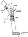
- FIG. 1shows an embodiment of the invention in the form of an active knee brace.
- FIGS. 2 a - fillustrate the respective structure and operation of electrostatic actuators.
- FIG. 3is a diagram showing the mechanical linkage between the actuator and the body attachment brace.
- FIG. 4is a block diagram showing the electronics used to drive and control the active muscle assistance device.
- FIG. 5is flowchart showing the modes of operation of a muscle assistance device.
- FIG. 6is a flowchart of the modes of operation of a knee joint muscle assistance device.
- FIG. 1shows an active muscle support brace according to one embodiment of the invention.
- the deviceis an active knee brace used to offload some of the stress from the quadriceps when extending the leg.
- other devicesare constructed with a suitable shape, but the principles presented here apply by analogy to such devices.
- the deviceis particularly useful in helping someone with muscle weakness in the every day tasks of standing, sitting, walking, climbing stairs and descending stairs.
- the devicecan also be used in other modes to help build muscle strength and to monitor movements for later analysis.
- the support to the muscleis defined by the position of the actuator 12 applying force to the moving parts of the brace. Namely, as the actuator 12 rotates, and with it the moving (rigid) parts of the brace, the position of the actuator 12 defines the relative position of the joint and thereby supporting the corresponding muscle.
- Each deviceprovides assistance and/or resistance to the muscles that extend and flex one joint.
- the devicedoes not directly connect to the muscle, but is attached in such a way that it can exert external forces to the limbs.
- the deviceis built from an underlying structural frame, padding, and straps (not shown) that can be tightened to the desired pressure.
- the frame structure with hinged lower and upper portions ( 14 and 16 ) as shownis preferably made of lightweight aluminum or carbon fiber.
- the frameis attached to the upper and lower leg with straps held by Velcro or clip-type connectors (not shown).
- a soft padding materialcushions the leg.
- the bracemay come in several standard sizes, or a custom brace can be constructed by making a mold of the leg and building a brace to precisely fit a replica of the leg constructed from the mold.
- the attachment of the device to the bodyis most easily understood with respect to a specific joint, the knee in this case.
- the structural frame of the deviceincludes a rigid portion above the knee connected to hinges 18 at the medial and lateral sides.
- the rigid structuregoes around the knee, typically around the posterior side, to connect both hinges together.
- On the upper portion of the brace 16the rigid portion extends up to the mid-thigh, and on the lower portion 14 , it continues down to the mid-calf. In the thigh and calf regions, the frame extends around from medial to lateral sides around approximately half the circumference of the leg. The remaining portion of the circumference is spanned by straps that can be tightened with clips, laces or Velcro closures.
- the rigid portioncan be either on the anterior or posterior side, but because this device must exert more pressure to extend the knee than to flex the knee, the preferred structure is to place more of the rigid structure on the posterior side with the straps on the anterior side.
- the number and width of strapscan vary, but the straps must be sufficient to hold the device in place with the axis of rotation of the hinge in approximately the same axis as that of rotation of the knee.
- the hingeitself may be more complex than a single pivot point to match the rotation of the knee.
- Cushioning materialmay be added to improve comfort.
- a manufacturermay choose to produce several standard sizes, each with enough adjustments to be comfortable for a range of patients, or the manufacturer may use a mold or tracing of the leg to produce individually customized devices.
- a microcontroller-based control systemdrives control information to the actuator, receives user input from a control panel function, and receives sensor information including joint position and external applied forces. For example, pressure information is obtained from the foot-pressure sensor 19 . Based on the sensor input and desired operation mode, the control system applies forces to resist the muscle, assist the muscle, or to allow the muscle to move the joint freely.
- the actuator 12is coupled to the brace to provide the force needed to assist or resist the leg muscle(s). Although it is intended to be relatively small in size, the actuator is preferably located on the lateral side to avoid interference with the other leg.
- the actuatoris coupled to both the upper and lower portions of the structural frame to provide assistance and resistance with leg extension and flexion.
- the actuator 12is structured to function as an electrostatic motor, linear or rotational (examples and implementations of electrostatic actuators can also be found in U.S. Pat. Nos. 6,525,446, 5,708,319, 5,541,465, 5,448,124, 5,239,222, which are incorporated herein by reference for this purpose).
- the ideabeing that the actuator is configured with the stator and rotor each having a plurality of electrodes electrically driven in opposite direction to cause an electrostatic field and, in turn, movement.
- the strength of the electrostatic fielddetermines the amount of torque produced by the actuator.
- the electrostatic motorcan be fabricated as a 2-dimension structure that can be easily stacked for producing higher power. This configuration is light weight relative to a 3-dimension structure of electromagnetic motors and can be constructed from light-weight polymers instead of heavy iron-based magnetic materials.
- DEMEDdual excitation multiphase electrostatic drive
- FIG. 2 aillustrates a basic linear electrostatic actuator with a stator and slider driven by a 3-phase a-c signal (alternating current signal).
- the three signalsare preferably offset by 2 ⁇ /3 and thus constitute the 3-phase a-c signals.
- the electrode strips (conductors 30 - 41 )are arranged sequentially in three groups, and the arranging order of the electrodes in the stator 24 is reversed with respect to the arranging order of the electrodes in the slider 22 .
- the electrodes strips in both the stator and sliderare implanted on an insulating dielectric material that allows the slider to glide over the stator without shorting the strips.
- the connecting order of the three phases in the sliderare reversed from that in the stator. So the induced potential waves in the slider 22 and stator 24 propagate in opposite directions, but their velocity is similar.
- the waves having offset phasesgenerate a Coulomb force between the electrode strips of the stator and slider from static electricity; and the Coulomb force moves the slider relative to the stator (in this configuration) along the arranged direction of the electrode strips.
- the slideris driven by electrostatic interaction between the two waves and its speed, v, is the differential between the speeds of the waves, i.e., twice the traveling wave velocity.
- FIG. 2 bshows the two parts of a rotary type electrostatic actuator: the stator 201 and the rotor 203 which when assembled is supported rotatably over the stator (not shown).
- the electrodes in the stator(D 1 , D 2 , D 3 ) are connected to the 3-phase a-c signal source, each receiving one phase high-voltage a-c signal independently.
- the rotoris kept at 0 volts potential (ground).
- the rotary type electrostatic actuatorcan be turned controllably by application of the a-c signals with the 2 ⁇ /3 phase offset between them.
- FIG. 2 cillustrates a basic theory of operation of both the rotary and linear actuators with a cutaway view of moving electrodes between two pairs of stationary electrodes (conductors above and below).
- the rotor electrodesare grounded (0 V) while the stator electrodes are driven by high ac voltage (+V).
- the voltage limitdepends on the breakdown characteristics of the insulating material 50 a,b and 52 .
- the insulating substrates 50 a,b and 52are formed from dielectric materials.
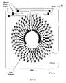
- the configuration of the stator and rotor electrodes in FIGS. 2 d - fare markedly different from the configuration in FIG. 2 b , and they allow higher voltages at smaller geometries.
- each of the three electrode groupsis driven at a different radial distance from the center of rotation and the difference in radial distance is sufficient to keep the three phases apart, thus allowing the narrow gaps between the electrodes of the same phase on the same radial circle.
- the voltagecan reach 1 to 4KV.
- the rotor electrode stripsare attracted to the stationary electrodes above and below, and although the upward and downward forces cancel each other the fringe forces pull (or rotate) the rotor as shown.
- the 3-phase signalsare applied to the connections on the stator. The phases are offset from each other and the voltages can be sequenced to drive the rotor in either direction.
- the Oxford ScaleThere is a standard scale of muscle strength called the Oxford Scale, and that scale goes from no contraction all the way up to full power.
- the actuatoris designed to supply sufficient power to the active support device for moving higher in the Oxford scale, say, from 2 to 3 in the scale, for one who can barely move the knee, to a level of substantial power strength.
- the stator and rotorcan be stacked sequentially to form a light weight, high power, high torque actuator.
- the battery compartmentis part of the actuator or is attached to another part of the structural frame with wires connected to the actuator.
- this configurationis lighter, more compact, and allows better and easier mobility.
- the control panelis part of the actuator or is attached to another part of the structural frame with wires connected to the actuator.
- Buttons of the control panelare preferably of the type that can be operated through clothing to allow the device mode to be changed when the device is hidden under the clothes.
- a device to aid in wrist movementhas elastic bands coupling a small actuator to the hand and wrist.
- Joints with more than one degree of freedommay have a single device to assist/resist the primary movement direction, or may have multiple actuators for different degrees of freedom.
- Other potential candidates for assistanceinclude the ankle, hip, elbow, shoulder and neck.
- the actuatoris of a rotary design type with the center of rotation of the actuator located close to the center of rotation of the knee joint.
- the tibiain flexion, the tibia lies beneath, and in line with, the midpoint of the patella (knee cap).
- the tibiaexternally rotates and the tibia tubercle comes to lie lateral to the midpoint of the patella.
- the tibial tuberclepoints to the inner half of the patella; in the extended knee it is in line with the outer half.
- the knee anatomyis constructed in such a way that a point on the lower leg does not move exactly in a circular arc.
- the coupling from the rotor to the lower bracerequires either an elastic coupling or a mechanical structure to couple the circular movement of the actuator with the near-circular movement of the portion of the brace attached to the lower leg.
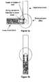
- FIGS. 3 a and 3 bshow a coupling mechanism that compensates for the movement of the center of rotation as the knee is flexed.
- FIG. 3 ashows the knee flexed at 90 degrees
- FIG. 3 bshows the knee fully extended.
- the center of rotation of the actuatoris centered at the upper end of the lower leg (tibia) when extended, but shifts towards the posterior of the tibia when the knee is flexed.
- the sliding mechanismallows the actuator to apply assistance or resistance force at any angle of flexure.
- the coupling mechanismcan be constructed using belts, gears, chains or linkages as is known in the art. These couplings can optionally change the ratio of actuator rotation to joint rotation.
- the linear actuatorhas the stator attached to the femur portion of the brace and the slider is indirectly connected to the tibial part of the brace via a connecting cable stretched over a pulley.
- the center of rotation of the pulleyis close to the center of rotation of the knee.
- FIG. 4is a block diagram showing the electronics and control system.
- the operation of the deviceis controlled by a program running in a microcontroller 402 .
- the microcontrolleris selected based on the scope of its internal functionality.
- the microcontrolleris the Cygnal 8051F310, although those skilled in the art will recognize that many current and future generation microcontrollers could be used.
- some of the internal functions of the 8051F310could be implemented with external components instead of internal to the microcontroller.
- the microcontroller 402is coupled to a control panel 404 to provide user control and information on the desired mode of operation.
- the control panelincludes a set of switches that can be read through the input buffers 418 of the microcontroller.
- the control panelalso may have a display panel or lights to display information such as operational mode and battery state.
- the control panelalso includes means to adjust the strength of assistance and resistance in order to customize the forces to the ability of the user.
- Another embodiment of the control panelis a wired or wireless connection port to a handheld, laptop or desktop computer. The connection port can also be used to communicate diagnostic information and previously stored performance information.
- Outputs of the microcontrollerare directed in part to the actuator 12 through a power driver circuit 410 and in part to the control panel 404 .
- the driver circuitconverts the outputs to high voltage phases to drive an electrostatic actuator.
- the power driver circuitincludes transformers and rectifiers to step up a-c waveforms generated by the microcontroller.
- an actuator as shown in FIGS. 2 d - fallows also pulsed signals rather than sinusoidal wave shaped signals and, accordingly, the power drivers are configured to generate high-voltage multi-phase pulsed signals.
- the power driver circuitis designed to generate high-current multi-phase signals.
- the operation mode of the muscle assistance deviceWhen the operation mode of the muscle assistance device is set to apply a force that opposes the motion of the joint, the energy input from that ‘external’ force must be absorbed by the control circuit. While this energy can be dissipated as heat in a resistive element, it is preferably returned to the battery in the actuator power supply 408 via a regeneration braking circuit 412 .
- This conceptis similar to “regenerative braking” found in some types of electric and hybrid vehicles to extend the operation time before the battery needs to be recharged.
- the microcontroller 402receives analog sensor information and converts it to digital form with the analog-to-digital converters 428 .
- the joint angle sensor 414provides the joint angle through a variable capacitor implemented as part of the electrostatic actuator (see e.g., FIGS. 2 d - f ).
- joint anglecan be supplied by a potentiometer or optical sensor of a type known in the art.
- the muscle stress sensor 416is implemented as a foot-pressure sensor wired to the active brace.
- This sensoris implemented with parallel plates separated by a dielectric that changes total capacitance under pressure.
- the foot sensoris a plastic sheet with conductive plates on both sides so that when pressure is applied on the knee the dielectric between the plates compresses. The change in the dielectric changes the capacitance and that capacitance change can be signaled to the microcomputer indicating to it how much pressure there is on the foot.
- pressure sensorsthat use resistive ink that changes resistance when pressure is applied on it. Other types of pressure sensors, such as strain gauges can be alternatively used to supply the pressure information. These sensors are configured to detect the need or intention to exert a muscle.
- the foot pressure sensor in conjunction with joint angle sensordetects the need to exert the quadriceps to keep the knee from buckling.
- Other types of sensorssuch as strain gauges, could detect the intension by measuring the expansion of the leg circumference near the quadriceps.
- surface mounted electrodes and signal processing electronicsmeasure the myoelectric signals controlling the quadriceps muscle.
- appropriate sensorsare used to detect either the need or intention to flex or extend the joint being assisted. It is noted that there is a certain threshold (minimum amount of pressure), say 5 pounds on the foot, above which movement of the actuator is triggered.
- Power for the muscle assistance devicecomes from one or more battery sources feeding power regulation circuits.
- the power for the logic and electronicsis derived from the primary battery (in the power supply 408 ).
- the batteries-charge stateis fed to the microcontroller for battery charge status display or for activating low battery alarms. Such alarms can be audible, visible, or a vibration mode of the actuator itself. Alternatively, a separate battery can power the electronics portion.
- FIG. 5the operation of the muscle assistance device is illustrated with a block diagram.
- the algorithm in this diagramis implemented by embedded program code executing in the microcontroller.
- the userselects a mode of operation 502 .
- the modesinclude: idle 506 , assist 508 , monitor 510 , rehabilitate 512 , and resist 514 .
- the actuatorIn the idle mode 506 , the actuator is set to neither impede nor assist movement of the joint. This is a key mode because it allows the device to move freely or remain in place when the user does not require assistance or resistance, or if battery has been drained to the point where the device can no longer operate. Idle mode requires the actuator to have the ability to allow free movement either with a clutch or an inherent free movement mode of the actuator, even when primary power is not available.
- the actuatorIn the monitor mode 510 , the actuator is in free movement mode (not driven), but the electronics is activated to record information for later analysis. Measured parameters include a sampling of inputs from the sensors and counts of movement repetitions in each activation mode. This data may be used later by physical therapists or physicians to monitor and alter rehabilitation programs.
- electrostatic actuatorscan be constructed from lightweight polymers and thin, low current conducting layers, substantially reducing their weight.
- the actuatoris programmed to assist movements initiated by the muscle. This mode augments the muscle, supplying extra strength and stamina to the user.
- the deviceIn the resist mode 514 , the device is operating as an exercise device. Any attempted movement is resisted by the actuator. Resistance intensity controls on the control panel determine the amount of added resistance.
- the deviceprovides a combination of assistance and resistance in order to speed recovery or muscle strength while minimizing the chance of injury. Assistance is provided whenever the joint is under severe external stress, and resistance is provided whenever there is movement while the muscle is under little stress.
- This modelevels out the muscle usage by reducing the maximum muscle force and increasing the minimum muscle force while moving. The average can be set to give a net increase in muscle exertion to promote strength training.
- a front panel controlprovides the means for setting the amplitude of the assistance and resistance.
- the indicia of a muscle under stressis provided as the output of the muscle stress sensor reaching a predetermined minimum threshold. That threshold is set by the microcontroller in response to front panel functions.
- the muscleis not under stress or if the resist mode 514 is selected, a further determination is made as to whether the joint is moving 522 .
- the output of the joint position sensortogether with its previous values, indicate whether the joint is currently in motion. If it is, and the mode is either rehabilitate or resist, the actuator is driven to apply force opposing the joint movement 524 .
- the amount of resistanceis set by the microcontroller in response to front panel settings. The resistance may be non-uniform with respect to joint position. The resistance may be customized to provide optimal training for a particular individual or for a class of rehabilitation.
- the actuatoris de-energized to allow free movement of the joint 526 . This is preferably accomplished by using an actuator that has an unpowered clutch mode.
- the actuatoris energized to apply force for assisting the muscle 528 .
- the actuator forcedirected to reduce the muscle stress.
- the amount of assistancemay depend on the amount of muscle stress, the joint angle, and the front panel input from the user. Typically, when there is stress on the muscle and the joint is flexed at a sharp angle, the largest assistance is required. In the case of knee assistance, this situation would be encountered when rising from a chair or other stressful activities.
- measurementsare recorded to a non-volatile memory such as the flash memory of the microcontroller (item 420 in FIG. 4 ). Measurements may include the state of all sensors, count of number of steps, time of each use, user panel settings, and battery condition. This and the step of uploading and analyzing the stored information are not shown in the diagram.
- FIG. 6is a flow diagram specific to an active knee assistance device. This diagram assumes a specific type of muscle stress sensor that measures the weight on the foot. Relative to the diagram of FIG. 5 , this diagram also shows a step ( 620 ) to determine whether the knee is bent or straight (within some variation). If the knee is straight, no bending force is needed 624 and power can be saved by putting the actuator in free-movement mode 630 . To prevent problems such as buckling of the knee, the transitions, i.e., de-energizing the actuator, in both FIGS. 5 and 6 may be dampened to assure that they are smooth and continuous.
- the software running on the microcontrollermay be architected in many different ways.
- a preferred architectureis to structure the embedded program code into subroutines or modules that communicate with each other and receive external interrupts (see item 424 in FIG. 4 ).
- the primary modulesinclude control panel, data acquisition, supervisor, actuator control, and monitor modules. A brief description of these modules is outlined below.
- the control panelresponds to changes in switch settings or remote communications to change the mode of operation.
- Settingsare saved in a nonvolatile memory, such as a bank of flash memory.
- the data acquisition modulereads the sensors and processes data into a format useful to the supervisor. For instance, reading position from a capacitive position sensor requires reading the current voltage, driving a new voltage through a resistance, then determining the RC time constant by reading back the capacitor voltage at a later time.
- the supervisor moduleis a state machine for keeping track of high-level mode of operation, joint angle, and movement direction. States are changed based on user input and sensor position information. The desired torque, direction and speed to the actuator control the functioning of this module.
- the supervisor modulemay also include training, assistance, or rehabilitation profiles customized to the individual.
- the actuator control moduleis operative to control the actuator (low level control) and includes a control loop to read fine position of the actuator and then drive phases to move the actuator in the desired direction with requested speed and torque.
- Torqueis proportional to the square of the driving voltage in an electrostatic actuator.
- the monitor modulemonitors the battery voltage and other parameters such as position, repetition rates, and sensor values. It also logs parameters for later analysis and generates alarms for parameters out of range. This module uses the front panel or vibration of the actuator to warn of low voltage from the battery.
- a number of variations in the above described system and methodinclude, for example, variations in the power sources, microcontroller functionality and the like.
- power sourcessuch as supercapacitors, organic batteries, disposable batteries and different types of rechargeable batteries can be used in place of a regular rechargeable battery.
- microcontroller functionalitycan be split among several processors or a different mix of internal and external functions.
- different types of braces, with or without hinges and support frames,may be used for attachment to the body, and they may be of different lengths.
- various ways of communicating the ‘weight-on-foot’may be used, either through wired or wireless connections to the control circuitry, or by making the brace long enough to reach the foot.
- the present inventionprovides a light weight active muscle assistance device.
- the present inventionhas been described in considerable detail with reference to certain preferred versions thereof, other versions are possible. Therefore, the spirit and scope of the appended claims should not be limited to the description of the preferred versions contained herein.
Landscapes
- Health & Medical Sciences (AREA)
- Epidemiology (AREA)
- Pain & Pain Management (AREA)
- Physical Education & Sports Medicine (AREA)
- Rehabilitation Therapy (AREA)
- Life Sciences & Earth Sciences (AREA)
- Animal Behavior & Ethology (AREA)
- General Health & Medical Sciences (AREA)
- Public Health (AREA)
- Veterinary Medicine (AREA)
- Rehabilitation Tools (AREA)
- Manipulator (AREA)
- Prostheses (AREA)
Abstract
Description
Claims (28)
Priority Applications (5)
| Application Number | Priority Date | Filing Date | Title |
|---|---|---|---|
| US11/221,452US7537573B2 (en) | 2002-11-25 | 2005-09-07 | Active muscle assistance and resistance device and method |
| US12/205,705US20090036804A1 (en) | 2002-11-25 | 2008-09-05 | Power regeneration in active muscle assistance device and method |
| US12/860,735US20100318006A1 (en) | 2002-11-25 | 2010-08-20 | Power regeneration in active muscle assistance device and method |
| US13/290,980US8679040B2 (en) | 2002-11-25 | 2011-11-07 | Intention-based therapy device and method |
| US14/225,186US20140207037A1 (en) | 2002-11-25 | 2014-03-25 | Intention-based therapy device and method |
Applications Claiming Priority (4)
| Application Number | Priority Date | Filing Date | Title |
|---|---|---|---|
| US42928902P | 2002-11-25 | 2002-11-25 | |
| US48588203P | 2003-07-08 | 2003-07-08 | |
| US10/704,483US6966882B2 (en) | 2002-11-25 | 2003-11-06 | Active muscle assistance device and method |
| US11/221,452US7537573B2 (en) | 2002-11-25 | 2005-09-07 | Active muscle assistance and resistance device and method |
Related Parent Applications (1)
| Application Number | Title | Priority Date | Filing Date |
|---|---|---|---|
| US10/704,483DivisionUS6966882B2 (en) | 2002-11-25 | 2003-11-06 | Active muscle assistance device and method |
Related Child Applications (1)
| Application Number | Title | Priority Date | Filing Date |
|---|---|---|---|
| US12/205,705ContinuationUS20090036804A1 (en) | 2002-11-25 | 2008-09-05 | Power regeneration in active muscle assistance device and method |
Publications (2)
| Publication Number | Publication Date |
|---|---|
| US20060004307A1 US20060004307A1 (en) | 2006-01-05 |
| US7537573B2true US7537573B2 (en) | 2009-05-26 |
Family
ID=32397191
Family Applications (6)
| Application Number | Title | Priority Date | Filing Date |
|---|---|---|---|
| US10/704,483Expired - LifetimeUS6966882B2 (en) | 2002-11-25 | 2003-11-06 | Active muscle assistance device and method |
| US11/221,452Expired - Fee RelatedUS7537573B2 (en) | 2002-11-25 | 2005-09-07 | Active muscle assistance and resistance device and method |
| US12/205,705AbandonedUS20090036804A1 (en) | 2002-11-25 | 2008-09-05 | Power regeneration in active muscle assistance device and method |
| US12/860,735AbandonedUS20100318006A1 (en) | 2002-11-25 | 2010-08-20 | Power regeneration in active muscle assistance device and method |
| US13/290,980Expired - LifetimeUS8679040B2 (en) | 2002-11-25 | 2011-11-07 | Intention-based therapy device and method |
| US14/225,186AbandonedUS20140207037A1 (en) | 2002-11-25 | 2014-03-25 | Intention-based therapy device and method |
Family Applications Before (1)
| Application Number | Title | Priority Date | Filing Date |
|---|---|---|---|
| US10/704,483Expired - LifetimeUS6966882B2 (en) | 2002-11-25 | 2003-11-06 | Active muscle assistance device and method |
Family Applications After (4)
| Application Number | Title | Priority Date | Filing Date |
|---|---|---|---|
| US12/205,705AbandonedUS20090036804A1 (en) | 2002-11-25 | 2008-09-05 | Power regeneration in active muscle assistance device and method |
| US12/860,735AbandonedUS20100318006A1 (en) | 2002-11-25 | 2010-08-20 | Power regeneration in active muscle assistance device and method |
| US13/290,980Expired - LifetimeUS8679040B2 (en) | 2002-11-25 | 2011-11-07 | Intention-based therapy device and method |
| US14/225,186AbandonedUS20140207037A1 (en) | 2002-11-25 | 2014-03-25 | Intention-based therapy device and method |
Country Status (4)
| Country | Link |
|---|---|
| US (6) | US6966882B2 (en) |
| EP (2) | EP1583497A4 (en) |
| AU (1) | AU2003287708A1 (en) |
| WO (1) | WO2004047928A2 (en) |
Cited By (55)
| Publication number | Priority date | Publication date | Assignee | Title |
|---|---|---|---|---|
| US20060046907A1 (en)* | 2004-08-11 | 2006-03-02 | Rastegar Jahangir S | Power generation devices and methods |
| US20060211956A1 (en)* | 2003-08-21 | 2006-09-21 | Yoshiyuki Sankai | Wearable action-assist device, and method and program for controlling wearable action-assist device |
| US20070155557A1 (en)* | 2005-12-30 | 2007-07-05 | Horst Robert W | Deflector assembly |
| US20080161937A1 (en)* | 2005-01-26 | 2008-07-03 | Yoshiyuki Sankai | Wearing-Type Motion Assistance Device and Program for Control |
| US20080188907A1 (en)* | 2007-02-02 | 2008-08-07 | Honda Motor Co., Ltd. | Controller for an Assistive Exoskeleton Based on Active Impedance |
| US20080195005A1 (en)* | 2007-02-14 | 2008-08-14 | Horst Robert W | Methods and devices for deep vein thrombosis prevention |
| US20090069865A1 (en)* | 2006-05-01 | 2009-03-12 | Eyal Lasko | Functional electrical stimulation systems |
| US20090204038A1 (en)* | 2008-02-08 | 2009-08-13 | Tibion Corporation | Multi-fit orthotic and mobility assistance apparatus |
| US20090209395A1 (en)* | 1998-04-23 | 2009-08-20 | Maresh Joseph D | Adjustable stride length exercise method and apparatus |
| US20090299483A1 (en)* | 2002-03-19 | 2009-12-03 | The Board Of Trustees Of The University Of Illinois | System and method for prosthetic fitting and balancing in joints |
| US20090306548A1 (en)* | 2008-06-05 | 2009-12-10 | Bhugra Kern S | Therapeutic method and device for rehabilitation |
| US20100036302A1 (en)* | 2008-08-07 | 2010-02-11 | Honda Motor Co., Ltd. | Walking assistance device |
| US20100039052A1 (en)* | 2008-08-14 | 2010-02-18 | Horst Robert W | Actuator system with a multi-motor assembly for extending and flexing a joint |
| US20100038983A1 (en)* | 2008-08-14 | 2010-02-18 | Kern Bhugra | Actuator system with a motor assembly and latch for extending and flexing a joint |
| US20100125229A1 (en)* | 2008-07-11 | 2010-05-20 | University Of Delaware | Controllable Joint Brace |
| US20100168622A1 (en)* | 2005-11-16 | 2010-07-01 | Amit Dar | Sensor device for gait enhancement |
| US20100204620A1 (en)* | 2009-02-09 | 2010-08-12 | Smith Jonathan A | Therapy and mobility assistance system |
| US20100204627A1 (en)* | 2003-10-29 | 2010-08-12 | The Regents Of The University Of California | Lower extremity enhancer |
| US20100286572A1 (en)* | 2007-07-11 | 2010-11-11 | Fraunhofer-Gesellschaft Zur Forderung Der Angewandten Forschung E.V. | Device and method for predicting a loss of control over a muscle |
| US20100318006A1 (en)* | 2002-11-25 | 2010-12-16 | Horst Robert W | Power regeneration in active muscle assistance device and method |
| US20110033835A1 (en)* | 2009-08-10 | 2011-02-10 | Honda Motor Co., Ltd. | Training device |
| US20110144547A1 (en)* | 2009-12-14 | 2011-06-16 | Takahisa Kusuura | Power apparatus, power system, and power control method |
| US20120046578A1 (en)* | 2010-08-19 | 2012-02-23 | University Of Delaware | Powered orthosis systems and methods |
| US20120086788A1 (en)* | 2010-10-12 | 2012-04-12 | Sony Corporation | Image processing apparatus, image processing method and program |
| US8639455B2 (en) | 2009-02-09 | 2014-01-28 | Alterg, Inc. | Foot pad device and method of obtaining weight data |
| RU2556598C1 (en)* | 2014-06-17 | 2015-07-10 | Федеральное государственное бюджетное образовательное учреждение высшего профессионального образования "Саратовский государственный технический университет имени Гагарина Ю.А." (СГТУ имени Гагарина Ю.А.) | Orthopaedic apparatus for relieving lower extremities of humans |
| US9095417B2 (en) | 2011-02-07 | 2015-08-04 | Bioness Neuromodulation Ltd. | Adjustable orthosis for electrical stimulation of a limb |
| US9351900B2 (en) | 2012-09-17 | 2016-05-31 | President And Fellows Of Harvard College | Soft exosuit for assistance with human motion |
| US9351855B2 (en) | 2008-06-16 | 2016-05-31 | Ekso Bionics, Inc. | Powered lower extremity orthotic and method of operation |
| US20160184985A1 (en)* | 2014-12-26 | 2016-06-30 | Samsung Electronics Co., Ltd. | Assisting torque setting method and apparatus |
| US9610208B2 (en) | 2008-05-20 | 2017-04-04 | Ekso Bionics, Inc. | Device and method for decreasing energy consumption of a person by use of a lower extremity exoskeleton |
| US9867985B2 (en) | 2014-03-24 | 2018-01-16 | Bioness Inc. | Systems and apparatus for gait modulation and methods of use |
| US9889058B2 (en) | 2013-03-15 | 2018-02-13 | Alterg, Inc. | Orthotic device drive system and method |
| TWI615129B (en)* | 2016-02-19 | 2018-02-21 | 財團法人資訊工業策進會 | Gait analysis system and method thereof |
| US20180315336A1 (en)* | 2017-04-27 | 2018-11-01 | Cal-Comp Big Data, Inc. | Lip gloss guide device and method thereof |
| US10278883B2 (en) | 2014-02-05 | 2019-05-07 | President And Fellows Of Harvard College | Systems, methods, and devices for assisting walking for developmentally-delayed toddlers |
| US10357381B2 (en) | 2014-12-08 | 2019-07-23 | Rehabilitation Instititute of Chicago | Powered and passive assistive device and related methods |
| US10434030B2 (en) | 2014-09-19 | 2019-10-08 | President And Fellows Of Harvard College | Soft exosuit for assistance with human motion |
| US20200081532A1 (en)* | 2018-09-06 | 2020-03-12 | Microsoft Technology Licensing, Llc | Selective restriction of skeletal joint motion |
| US10617590B2 (en) | 2016-12-26 | 2020-04-14 | Samsung Electronics Co., Ltd. | Motion assistance apparatus |
| US10843332B2 (en) | 2013-05-31 | 2020-11-24 | President And Fellow Of Harvard College | Soft exosuit for assistance with human motion |
| US10860102B2 (en) | 2019-05-08 | 2020-12-08 | Microsoft Technology Licensing, Llc | Guide for supporting flexible articulating structure |
| US10864100B2 (en) | 2014-04-10 | 2020-12-15 | President And Fellows Of Harvard College | Orthopedic device including protruding members |
| US11014804B2 (en) | 2017-03-14 | 2021-05-25 | President And Fellows Of Harvard College | Systems and methods for fabricating 3D soft microstructures |
| US11023047B2 (en) | 2018-05-01 | 2021-06-01 | Microsoft Technology Licensing, Llc | Electrostatic slide clutch with bidirectional drive circuit |
| US11036295B2 (en) | 2016-11-23 | 2021-06-15 | Microsoft Technology Licensing, Llc | Electrostatic slide clutch |
| US11054905B2 (en) | 2019-05-24 | 2021-07-06 | Microsoft Technology Licensing, Llc | Motion-restricting apparatus with common base electrode |
| US11061476B2 (en) | 2019-05-24 | 2021-07-13 | Microsoft Technology Licensing, Llc | Haptic feedback apparatus |
| US11077300B2 (en) | 2016-01-11 | 2021-08-03 | Bioness Inc. | Systems and apparatus for gait modulation and methods of use |
| US11273069B2 (en) | 2016-01-12 | 2022-03-15 | The Trustees Of Columbia University In The City Of New York | Wearable apparatuses, methods, and systems for diagnosis, analysis, therapy and other uses |
| US11324655B2 (en) | 2013-12-09 | 2022-05-10 | Trustees Of Boston University | Assistive flexible suits, flexible suit systems, and methods for making and control thereof to assist human mobility |
| US20220221330A1 (en)* | 2019-05-29 | 2022-07-14 | Nec Corporation | Information processing device, weight estimation device, weight estimation system, information processing method, and storage medium |
| TWI776713B (en)* | 2021-10-19 | 2022-09-01 | 國家中山科學研究院 | Smart muscle strength training system and wearable device |
| US11498203B2 (en) | 2016-07-22 | 2022-11-15 | President And Fellows Of Harvard College | Controls optimization for wearable systems |
| US11590046B2 (en) | 2016-03-13 | 2023-02-28 | President And Fellows Of Harvard College | Flexible members for anchoring to the body |
Families Citing this family (231)
| Publication number | Priority date | Publication date | Assignee | Title |
|---|---|---|---|---|
| US7650204B2 (en)* | 2001-06-29 | 2010-01-19 | Honda Motor Co., Ltd. | Active control of an ankle-foot orthosis |
| US7684896B2 (en)* | 2001-06-29 | 2010-03-23 | Honda Motor Co., Ltd. | System and method of estimating joint loads using an approach of closed form dynamics |
| US7135003B2 (en)* | 2001-06-29 | 2006-11-14 | Honda Giken Kogyo Kabushiki Kaisha | Feedback estimation of joint forces and joint moments |
| US7390309B2 (en)* | 2002-09-23 | 2008-06-24 | Honda Motor Co., Ltd. | Human assist system using gravity compensation control system and method using multiple feasibility parameters |
| US7774177B2 (en) | 2001-06-29 | 2010-08-10 | Honda Motor Co., Ltd. | Exoskeleton controller for a human-exoskeleton system |
| US7623944B2 (en)* | 2001-06-29 | 2009-11-24 | Honda Motor Co., Ltd. | System and method of estimating joint loads in a three-dimensional system |
| US7469166B2 (en)* | 2001-06-29 | 2008-12-23 | Honda Motor Co., Ltd. | System and method of predicting novel motion in a serial chain system |
| US7217247B2 (en)* | 2002-09-23 | 2007-05-15 | Honda Giken Kogyo Kabushiki Kaisha | Gravity compensation method in a human assist system and a human assist system with gravity compensation control |
| JP4133216B2 (en)* | 2001-10-29 | 2008-08-13 | 本田技研工業株式会社 | Human assist device simulation system, method, and computer program |
| US20040064195A1 (en) | 2002-07-15 | 2004-04-01 | Hugh Herr | Variable-mechanical-impedance artificial legs |
| US7736394B2 (en) | 2002-08-22 | 2010-06-15 | Victhom Human Bionics Inc. | Actuated prosthesis for amputees |
| CN100506189C (en) | 2002-08-22 | 2009-07-01 | 维克多姆人体机械公司 | Actuated leg prosthesis for above-knee amputees |
| US7402142B2 (en)* | 2002-09-23 | 2008-07-22 | Honda Giken Kogyo Kabushiki Kaisha | Method and processor for obtaining moments and torques in a biped walking system |
| US7396337B2 (en)* | 2002-11-21 | 2008-07-08 | Massachusetts Institute Of Technology | Powered orthotic device |
| US7182738B2 (en)* | 2003-04-23 | 2007-02-27 | Marctec, Llc | Patient monitoring apparatus and method for orthosis and other devices |
| US7204814B2 (en)* | 2003-05-29 | 2007-04-17 | Muscle Tech Ltd. | Orthodynamic rehabilitator |
| US7239065B2 (en)* | 2003-07-08 | 2007-07-03 | Tibion Corporation | Electrostatic actuator with fault tolerant electrode structure |
| EP1643905A2 (en)* | 2003-07-10 | 2006-04-12 | Neurocom International, Inc | Apparatus and method for characterizing contributions of forces associated with a body part of a subject |
| US8075633B2 (en)* | 2003-09-25 | 2011-12-13 | Massachusetts Institute Of Technology | Active ankle foot orthosis |
| US7815689B2 (en) | 2003-11-18 | 2010-10-19 | Victhom Human Bionics Inc. | Instrumented prosthetic foot |
| US20050107889A1 (en) | 2003-11-18 | 2005-05-19 | Stephane Bedard | Instrumented prosthetic foot |
| US7491194B1 (en)* | 2004-02-03 | 2009-02-17 | David Oliwa | Remote control valve for urine collection bag |
| US20060293617A1 (en)* | 2004-02-05 | 2006-12-28 | Reability Inc. | Methods and apparatuses for rehabilitation and training |
| US8888723B2 (en)* | 2004-02-05 | 2014-11-18 | Motorika Limited | Gait rehabilitation methods and apparatuses |
| JP4695605B2 (en)* | 2004-02-05 | 2011-06-08 | モトリカ リミテッド | Neuromuscular stimulation |
| US8112155B2 (en)* | 2004-02-05 | 2012-02-07 | Motorika Limited | Neuromuscular stimulation |
| WO2005074372A2 (en) | 2004-02-05 | 2005-08-18 | Motorika Inc. | Methods and apparatus for rehabilitation and training |
| US8915871B2 (en)* | 2004-02-05 | 2014-12-23 | Motorika Limited | Methods and apparatuses for rehabilitation exercise and training |
| US8057550B2 (en) | 2004-02-12 | 2011-11-15 | össur hf. | Transfemoral prosthetic systems and methods for operating the same |
| US7637959B2 (en) | 2004-02-12 | 2009-12-29 | össur hf | Systems and methods for adjusting the angle of a prosthetic ankle based on a measured surface angle |
| CA2559890C (en) | 2004-03-10 | 2014-01-07 | Ossur Hf | Control system and method for a prosthetic knee |
| US20050283257A1 (en)* | 2004-03-10 | 2005-12-22 | Bisbee Charles R Iii | Control system and method for a prosthetic knee |
| EP1774300A4 (en)* | 2004-07-07 | 2008-07-02 | Home Guardian Llc | Instrumented mobility assistance device |
| EP1838270B1 (en)* | 2004-08-25 | 2009-07-22 | Motorika Limited | Motor training with brain plasticity |
| US7429253B2 (en)* | 2004-09-21 | 2008-09-30 | Honda Motor Co., Ltd. | Walking assistance system |
| WO2006037101A2 (en)* | 2004-09-27 | 2006-04-06 | Massachusetts Institute Of Technology | Ankle interface |
| WO2006052954A2 (en) | 2004-11-09 | 2006-05-18 | Northeastern University | Electro-rheological fluid brake and actuator devices and orthotic devices using the same |
| JP2008522708A (en)* | 2004-12-07 | 2008-07-03 | タイラートン インターナショナル インコーポレイテッド | Apparatus and methods for training, rehabilitation, and / or support |
| JP4541867B2 (en)* | 2004-12-16 | 2010-09-08 | 本田技研工業株式会社 | External force control method, external force control system, and external force control program |
| CA2863933C (en) | 2004-12-22 | 2018-08-07 | Ossur Hf | Systems and methods for processing limb motion |
| US7901368B2 (en)* | 2005-01-06 | 2011-03-08 | Braingate Co., Llc | Neurally controlled patient ambulation system |
| US8095209B2 (en) | 2005-01-06 | 2012-01-10 | Braingate Co., Llc | Biological interface system with gated control signal |
| EP1845849B1 (en)* | 2005-01-18 | 2019-04-10 | The Regents of The University of California | Lower extremity exoskeleton |
| CA2601778C (en) | 2005-02-02 | 2014-08-12 | Ossur Hf | Prosthetic and orthotic systems usable for rehabilitation |
| EP1843724B1 (en) | 2005-02-02 | 2018-07-25 | Össur hf | Sensing systems and methods for monitoring gait dynamics |
| US8801802B2 (en) | 2005-02-16 | 2014-08-12 | össur hf | System and method for data communication with a mechatronic device |
| US10080672B2 (en) | 2005-03-31 | 2018-09-25 | Bionx Medical Technologies, Inc. | Hybrid terrain-adaptive lower-extremity systems |
| US10307272B2 (en) | 2005-03-31 | 2019-06-04 | Massachusetts Institute Of Technology | Method for using a model-based controller for a robotic leg |
| US20070162152A1 (en) | 2005-03-31 | 2007-07-12 | Massachusetts Institute Of Technology | Artificial joints using agonist-antagonist actuators |
| US8512415B2 (en) | 2005-03-31 | 2013-08-20 | Massachusetts Institute Of Technology | Powered ankle-foot prothesis |
| US11278433B2 (en) | 2005-03-31 | 2022-03-22 | Massachusetts Institute Of Technology | Powered ankle-foot prosthesis |
| US20070043449A1 (en) | 2005-03-31 | 2007-02-22 | Massachusetts Institute Of Technology | Artificial ankle-foot system with spring, variable-damping, and series-elastic actuator components |
| US8500823B2 (en) | 2005-03-31 | 2013-08-06 | Massachusetts Institute Of Technology | Powered artificial knee with agonist-antagonist actuation |
| US20060249315A1 (en) | 2005-03-31 | 2006-11-09 | Massachusetts Institute Of Technology | Artificial human limbs and joints employing actuators, springs, and variable-damper elements |
| US20070123997A1 (en) | 2005-03-31 | 2007-05-31 | Massachusetts Institute Of Technology | Exoskeletons for running and walking |
| US8864846B2 (en) | 2005-03-31 | 2014-10-21 | Massachusetts Institute Of Technology | Model-based neuromechanical controller for a robotic leg |
| PL1874239T3 (en)* | 2005-04-13 | 2014-10-31 | Univ California | Semi-powered lower extremity exoskeleton |
| SE528516C2 (en) | 2005-04-19 | 2006-12-05 | Lisa Gramnaes | Combined active and passive leg prosthesis system and a method for performing a movement cycle with such a system |
| DE102005022005B4 (en)* | 2005-05-09 | 2014-10-30 | Anna Gutmann | Method and device for facilitating the movement control of body parts |
| US8082062B2 (en)* | 2005-06-10 | 2011-12-20 | Honda Motor Co., Ltd. | Regenerative actuation in motion control |
| JP4417300B2 (en)* | 2005-07-13 | 2010-02-17 | 本田技研工業株式会社 | Walking assist device |
| EP1946429B1 (en)* | 2005-08-10 | 2017-06-21 | Bionic Power Inc. | Methods and apparatus for harvesting biomechanical energy |
| JP2007054086A (en)* | 2005-08-22 | 2007-03-08 | Kochi Univ Of Technology | Movement assistive device |
| US7485152B2 (en) | 2005-08-26 | 2009-02-03 | The Ohio Willow Wood Company | Prosthetic leg having electronically controlled prosthetic knee with regenerative braking feature |
| US8852292B2 (en)* | 2005-09-01 | 2014-10-07 | Ossur Hf | System and method for determining terrain transitions |
| JP3950149B2 (en)* | 2005-09-02 | 2007-07-25 | 本田技研工業株式会社 | Exercise assistance device |
| CN101282696B (en)* | 2005-10-11 | 2012-12-05 | 松下电器产业株式会社 | Motion assistance apparatus and method |
| AU2007223733B2 (en)* | 2006-03-09 | 2013-01-10 | The Regents Of The University Of California | Power generating leg |
| JP4712620B2 (en)* | 2006-06-12 | 2011-06-29 | 本田技研工業株式会社 | Control device for walking aids |
| US8849457B2 (en)* | 2006-07-17 | 2014-09-30 | Raytheon Company | Contact displacement actuator system |
| EP2079361B1 (en)* | 2006-09-19 | 2013-01-09 | Myomo, Inc. | Powered orthotic device |
| US8585620B2 (en) | 2006-09-19 | 2013-11-19 | Myomo, Inc. | Powered orthotic device and method of using same |
| US10758394B2 (en) | 2006-09-19 | 2020-09-01 | Myomo, Inc. | Powered orthotic device and method of using same |
| CA2673399C (en) | 2007-01-05 | 2017-08-29 | Victhom Human Bionics, Inc. | Joint actuation mechanism for a prosthetic and/or orthotic device having a compliant transmission |
| CA2676067C (en) | 2007-01-19 | 2017-06-20 | Victhom Human Bionics, Inc. | Reactive layer control system for prosthetic and orthotic devices |
| JP5232177B2 (en)* | 2007-02-28 | 2013-07-10 | レイセオン カンパニー | Opposing fluid control systems for active and passive actuation of actuators |
| US8051764B2 (en)* | 2007-02-28 | 2011-11-08 | Raytheon Company | Fluid control system having selective recruitable actuators |
| JP5283401B2 (en)* | 2007-03-22 | 2013-09-04 | 国立大学法人 筑波大学 | Rehabilitation support device |
| JP5326223B2 (en)* | 2007-05-14 | 2013-10-30 | 沖電気工業株式会社 | Robot for rehabilitation education |
| US7854708B2 (en)* | 2007-05-22 | 2010-12-21 | Kai Yu Tong | Multiple joint linkage device |
| US8540652B2 (en)* | 2007-05-22 | 2013-09-24 | The Hong Kong Polytechnic University | Robotic training system with multi-orientation module |
| JP4789117B2 (en)* | 2007-08-03 | 2011-10-12 | 本田技研工業株式会社 | Walking assist device |
| ITKR20070004A1 (en)* | 2007-12-04 | 2009-06-05 | Istituto S Anna Di Ezio Puglie | SYSTEM AND METHOD FOR REHABILITATION |
| DE102008027639A1 (en)* | 2008-06-06 | 2009-12-24 | Fior & Gentz Gmbh | Orthotic joint e.g. human anatomic knee joint, for use in orthopedic for forming leg brace of patient, has sensor unit including two sensors, and gyroscope for detecting person defined information in moving and/or resting state |
| US9439828B2 (en)* | 2008-07-08 | 2016-09-13 | Avex, L.L.C. | Foot compression system |
| AU2009273927B2 (en)* | 2008-07-23 | 2014-09-18 | Ekso Bionics, Inc. | An exoskeleton and method of reducing the energy consumption of a person in motion coupled to an exoskeleton device |
| US20110213599A1 (en)* | 2008-08-28 | 2011-09-01 | Raytheon Company | Method of Sizing Actuators for a Biomimetic Mechanical Joint |
| US8731716B2 (en) | 2008-08-28 | 2014-05-20 | Raytheon Company | Control logic for biomimetic joint actuators |
| EP2337527A1 (en)* | 2008-08-28 | 2011-06-29 | Raytheon Sarcos, LLC | A biomimetic mechanical joint |
| KR20110074520A (en) | 2008-09-04 | 2011-06-30 | 아이워크, 아이엔씨. | Hybrid Terrain-Adaptive Prosthetic Systems |
| US20110082566A1 (en)* | 2008-09-04 | 2011-04-07 | Herr Hugh M | Implementing a stand-up sequence using a lower-extremity prosthesis or orthosis |
| US20100198124A1 (en)* | 2009-01-30 | 2010-08-05 | Kern Bhugra | System and method for controlling the joint motion of a user based on a measured physiological property |
| IT1393776B1 (en)* | 2009-04-03 | 2012-05-08 | Fond Istituto Italiano Di Tecnologia | ELASTIC ROTARY ACTUATOR, PARTICULARLY FOR ROBOTIC APPLICATIONS, AND METHOD FOR ITS CONTROL |
| US20110112447A1 (en)* | 2009-10-05 | 2011-05-12 | The Board Of Trustees Of The University Of Illinois | Portable active fluid powered ankle-foot orthosis |
| SG183388A1 (en)* | 2010-03-08 | 2012-09-27 | Carrier Corp | Capacity and pressure control in a transport refrigeration system |
| WO2011114457A1 (en)* | 2010-03-17 | 2011-09-22 | トヨタ自動車株式会社 | Leg assistance device |
| CN102892388A (en) | 2010-04-05 | 2013-01-23 | Iwalk股份有限公司 | Controlling torque in a prosthesis or orthosis |
| JP4998623B2 (en)* | 2010-04-16 | 2012-08-15 | トヨタ自動車株式会社 | Rotation limiting device, robot joint and walking aid |
| CA2812127C (en) | 2010-09-17 | 2017-11-28 | Ekso Bionics | Human machine interface for human exoskeleton |
| US9682006B2 (en) | 2010-09-27 | 2017-06-20 | Vanderbilt University | Movement assistance devices |
| WO2012044621A1 (en)* | 2010-09-27 | 2012-04-05 | Vanderbilt University | Movement assistance device |
| CA2812955C (en) | 2010-09-29 | 2018-09-04 | Ossur Hf | Prosthetic and orthotic devices and methods and systems for controlling the same |
| AU2011311954B2 (en)* | 2010-10-06 | 2014-08-07 | Ekso Bionics | Human machine interfaces for lower extremity orthotics |
| KR20120071555A (en)* | 2010-12-23 | 2012-07-03 | 한국전자통신연구원 | Apparatus for rehabilitation robot |
| JP5642534B2 (en) | 2010-12-27 | 2014-12-17 | Cyberdyne株式会社 | Wearable motion assist device, its interface device and program |
| WO2012096956A1 (en) | 2011-01-10 | 2012-07-19 | Iwalk, Inc. | Powered joint orthosis |
| US20120259430A1 (en) | 2011-01-12 | 2012-10-11 | Zhixiu Han | Controlling powered human augmentation devices |
| US9687377B2 (en) | 2011-01-21 | 2017-06-27 | Bionx Medical Technologies, Inc. | Terrain adaptive powered joint orthosis |
| USD667952S1 (en)* | 2011-02-28 | 2012-09-25 | Massimo Amenduni Gresele | Medical instrument |
| WO2012125562A1 (en) | 2011-03-11 | 2012-09-20 | Iwalk, Inc. | Biomimetic joint actuators |
| JP6092183B2 (en)* | 2011-03-21 | 2017-03-08 | エスアールアイ インターナショナルSRI International | Mobile robot manipulator system |
| US9789603B2 (en) | 2011-04-29 | 2017-10-17 | Sarcos Lc | Teleoperated robotic system |
| US9060884B2 (en) | 2011-05-03 | 2015-06-23 | Victhom Human Bionics Inc. | Impedance simulating motion controller for orthotic and prosthetic applications |
| KR101283143B1 (en) | 2011-05-04 | 2013-07-05 | 서강대학교산학협력단 | Knee Joint Assistive Device |
| US10278885B1 (en) | 2011-07-29 | 2019-05-07 | Leonis Medical Corporation | Method and system for control and operation of motorized orthotic exoskeleton joints |
| US9545353B2 (en) | 2011-07-29 | 2017-01-17 | Leonis Medical Corporation | Methods of operating an exoskeleton for gait assistance and rehabilitation |
| US11400010B2 (en) | 2011-07-29 | 2022-08-02 | Leonis Medical Corporation | Method and system for control and operation of motorized orthotic exoskeleton joints |
| US9072941B2 (en)* | 2011-08-11 | 2015-07-07 | The Charles Stark Draper Laboratory, Inc. | Exoskeleton suit for adaptive resistance to movement |
| US8736087B2 (en) | 2011-09-01 | 2014-05-27 | Bionic Power Inc. | Methods and apparatus for control of biomechanical energy harvesting |
| WO2013067407A1 (en) | 2011-11-02 | 2013-05-10 | Iwalk, Inc. | Biomimetic transfemoral prosthesis |
| US9532877B2 (en) | 2011-11-11 | 2017-01-03 | Springactive, Inc. | Robotic device and method of using a parallel mechanism |
| US10543109B2 (en) | 2011-11-11 | 2020-01-28 | Össur Iceland Ehf | Prosthetic device and method with compliant linking member and actuating linking member |
| US9032635B2 (en) | 2011-12-15 | 2015-05-19 | Massachusetts Institute Of Technology | Physiological measurement device or wearable device interface simulator and method of use |
| US9498401B2 (en) | 2011-12-20 | 2016-11-22 | Massachusetts Institute Of Technology | Robotic system for simulating a wearable device and method of use |
| CN102631276B (en)* | 2011-12-31 | 2015-04-15 | 中国科学院深圳先进技术研究院 | Interaction system for rehabilitation training robot |
| US8968227B2 (en)* | 2012-01-23 | 2015-03-03 | Adicep Technologies, Inc. | Knee Brace |
| US9682005B2 (en)* | 2012-02-24 | 2017-06-20 | Massachusetts Institute Of Technology | Elastic element exoskeleton and method of using same |
| US9044346B2 (en) | 2012-03-29 | 2015-06-02 | össur hf | Powered prosthetic hip joint |
| US9221177B2 (en) | 2012-04-18 | 2015-12-29 | Massachusetts Institute Of Technology | Neuromuscular model-based sensing and control paradigm for a robotic leg |
| CN102670342B (en)* | 2012-05-07 | 2013-12-04 | 北京航空航天大学 | Axisymmetric electrorheological fluid damping knee-joint orthosis |
| US9616580B2 (en) | 2012-05-14 | 2017-04-11 | Sarcos Lc | End effector for a robotic arm |
| WO2013188510A2 (en) | 2012-06-12 | 2013-12-19 | Iwalk, Inc. | Prosthetic, orthotic or exoskeleton device |
| JP5848203B2 (en)* | 2012-07-13 | 2016-01-27 | 株式会社デンソー | Body support device |
| US8845566B2 (en) | 2012-08-02 | 2014-09-30 | The Regents Of The University Of Michigan | Active exoskeletal spinal orthosis and method of orthotic treatment |
| WO2014088505A2 (en)* | 2012-12-06 | 2014-06-12 | Centri Ab | Knee joint prosthesis |
| US9433552B2 (en)* | 2013-01-17 | 2016-09-06 | Lg Electronics Inc. | Electric walking assistant device |
| US10524948B2 (en) | 2013-01-22 | 2020-01-07 | Orthocare Medical Equipment, Llc | Micro-adjustable telescoping arms for orthopedic braces |
| US9561118B2 (en) | 2013-02-26 | 2017-02-07 | össur hf | Prosthetic foot with enhanced stability and elastic energy return |
| US8870798B2 (en)* | 2013-03-14 | 2014-10-28 | CyMedica, Inc. | Systems and methods for treating human joints |
| EP2968052B1 (en)* | 2013-03-14 | 2021-08-11 | Ekso Bionics, Inc. | Powered orthotic system for cooperative overground rehabilitation |
| US9072898B2 (en) | 2013-03-14 | 2015-07-07 | CyMedica, Inc. | System and methods for treating or supporting human joints or a portion of the human body |
| WO2014159114A1 (en) | 2013-03-14 | 2014-10-02 | össur hf | Prosthetic ankle: a method of controlling based on adaptation to speed |
| US9675514B2 (en) | 2013-03-15 | 2017-06-13 | Bionik Laboratories, Inc. | Transmission assembly for use in an exoskeleton apparatus |
| US11353084B2 (en)* | 2013-03-15 | 2022-06-07 | Clearmotion Acquisition I Llc | Rotary actuator driven vibration isolation |
| US9855181B2 (en) | 2013-03-15 | 2018-01-02 | Bionik Laboratories, Inc. | Transmission assembly for use in an exoskeleton apparatus |
| US9808390B2 (en) | 2013-03-15 | 2017-11-07 | Bionik Laboratories Inc. | Foot plate assembly for use in an exoskeleton apparatus |
| US9421143B2 (en) | 2013-03-15 | 2016-08-23 | Bionik Laboratories, Inc. | Strap assembly for use in an exoskeleton apparatus |
| KR101667179B1 (en)* | 2013-05-30 | 2016-10-17 | 호메이윤 카제루니 | User-coupled human-machine interface system and a control method of an exoskeleton thereof |
| CA2855148C (en)* | 2013-06-21 | 2020-07-14 | Queen's University At Kingston | Biomechanical electrical power generation apparatus |
| US20150025423A1 (en) | 2013-07-19 | 2015-01-22 | Bionik Laboratories, Inc. | Control system for exoskeleton apparatus |
| CN106029039B (en) | 2013-12-16 | 2018-03-27 | 麻省理工学院 | The optimal design of lower limb exoskeleton or KAFO |
| US10611020B2 (en) | 2013-12-19 | 2020-04-07 | Roam Robotics Inc. | Pneumatic exomuscle system and method |
| WO2015157723A1 (en) | 2014-04-11 | 2015-10-15 | össur hf | Prosthetic foot with removable flexible members |
| US9265685B1 (en)* | 2014-05-01 | 2016-02-23 | University Of South Florida | Compliant bimanual rehabilitation device and method of use thereof |
| US10766133B2 (en) | 2014-05-06 | 2020-09-08 | Sarcos Lc | Legged robotic device utilizing modifiable linkage mechanism |
| US20160213496A1 (en)* | 2015-01-28 | 2016-07-28 | Steering Solutions Ip Holding Corporation | Integrated power generation for human exoskeletons and method of generating power |
| KR101609505B1 (en)* | 2015-02-04 | 2016-04-05 | 현대중공업 주식회사 | Gait rehabilitation control system and the method |
| WO2016160624A1 (en) | 2015-03-27 | 2016-10-06 | Other Lab Llc | Lower-leg exoskeleton system and method |
| KR101677935B1 (en)* | 2015-04-07 | 2016-11-22 | 주식회사 에스지메카트로닉스 | Joint Driving Unit And Joint Structure Of Lower-limb Assistance Robot Having The Same |
| US10390973B2 (en) | 2015-05-11 | 2019-08-27 | The Hong Kong Polytechnic University | Interactive exoskeleton robotic knee system |
| KR20160148074A (en)* | 2015-06-15 | 2016-12-26 | 주식회사 에스지메카트로닉스 | Driving unit of multi-joint robot |
| JP2018519004A (en) | 2015-06-15 | 2018-07-19 | マイオモ インコーポレイテッド | Electric straightening device and method of using the same |
| KR102529617B1 (en) | 2015-07-23 | 2023-05-09 | 삼성전자주식회사 | Method for walking assist, and devices operating the same |
| CN105114444B (en)* | 2015-09-10 | 2018-05-01 | 河南科技大学 | A kind of adjustable articulation mechanism of rotary damping power |
| CN105030484B (en)* | 2015-09-10 | 2018-05-01 | 河南科技大学 | A kind of mechanical arm master-slave operation equipment with damping feedback |
| EP3317789A1 (en)* | 2015-12-14 | 2018-05-09 | Parker-Hannifin Corporation | Control system utilizing a mobile application for a legged mobility exoskeleton device |
| US10195099B2 (en) | 2016-01-11 | 2019-02-05 | Bionic Power Inc. | Method and system for intermittently assisting body motion |
| JP6678334B2 (en)* | 2016-03-09 | 2020-04-08 | パナソニックIpマネジメント株式会社 | Life support system, walking assist robot and life support method |
| WO2018001348A1 (en)* | 2016-06-30 | 2018-01-04 | 上海傅利叶智能科技有限公司 | Upper limb rehabilitation training machine |
| CN105952595A (en)* | 2016-07-06 | 2016-09-21 | 深圳市智携科技有限公司 | Power generation system and human body power generation device |
| CN105997438B (en)* | 2016-07-18 | 2019-02-12 | 浙江大学 | A self-adjusting wearable leg power brace |
| CN107657068A (en)* | 2016-07-25 | 2018-02-02 | 中慧医学成像有限公司 | Brace design method and system |
| FR3054434B1 (en) | 2016-07-28 | 2021-09-10 | Safran Electronics & Defense | EXOSKELETON STRUCTURE FOR USER STRAIN ASSISTANCE |
| CN106239481A (en)* | 2016-08-31 | 2016-12-21 | 南京晨光集团有限责任公司 | A kind of exoskeleton robot micro hydraulic servosystem |
| WO2018065913A1 (en)* | 2016-10-04 | 2018-04-12 | Ecole Polytechnique Federale De Lausanne (Epfl) | Modular and minimally constraining lower limb exoskeleton for enhanced mobility and balance augmentation |
| US10919161B2 (en) | 2016-11-11 | 2021-02-16 | Sarcos Corp. | Clutched joint modules for a robotic system |
| US10821614B2 (en) | 2016-11-11 | 2020-11-03 | Sarcos Corp. | Clutched joint modules having a quasi-passive elastic actuator for a robotic assembly |
| JP6508167B2 (en)* | 2016-11-11 | 2019-05-08 | トヨタ自動車株式会社 | Walking training system |
| US10828767B2 (en) | 2016-11-11 | 2020-11-10 | Sarcos Corp. | Tunable actuator joint modules having energy recovering quasi-passive elastic actuators with internal valve arrangements |
| US10765537B2 (en) | 2016-11-11 | 2020-09-08 | Sarcos Corp. | Tunable actuator joint modules having energy recovering quasi-passive elastic actuators for use within a robotic system |
| ES2969892T3 (en) | 2017-02-03 | 2024-05-23 | Roam Robotics Inc | System and method for user intent recognition |
| KR101896306B1 (en)* | 2017-02-27 | 2018-09-10 | 인하대학교 산학협력단 | Device for guiding human body joint motion |
| US10420663B2 (en) | 2017-05-01 | 2019-09-24 | Verily Life Sciences Llc | Handheld articulated user-assistive device with behavior control modes |
| USD1010028S1 (en) | 2017-06-22 | 2024-01-02 | Boost Treadmills, LLC | Unweighting exercise treadmill |
| IL272623B2 (en) | 2017-08-29 | 2024-12-01 | Roam Robotics Inc | System and method for detecting semi-guided intent |
| US10663016B2 (en) | 2017-10-09 | 2020-05-26 | Microsoft Technology Licensing, Llc | Electrostatic rotary clutch |
| US11241353B2 (en) | 2017-11-09 | 2022-02-08 | The Curators Of The University Of Missouri | Knee flexion device and associated method of use |
| US10843330B2 (en) | 2017-12-07 | 2020-11-24 | Sarcos Corp. | Resistance-based joint constraint for a master robotic system |
| US11331809B2 (en) | 2017-12-18 | 2022-05-17 | Sarcos Corp. | Dynamically controlled robotic stiffening element |
| IT201800003889A1 (en)* | 2018-03-23 | 2018-06-23 | Nimble Robotics S R L | Gait rehabilitation system and weight support device for this system |
| CN108937949B (en)* | 2018-05-23 | 2020-11-20 | 常州市第一人民医院 | An ankle pump exercise counter and its working method |
| WO2020046142A1 (en)* | 2018-08-28 | 2020-03-05 | Opum Technologies Limited | Orthosis or exoskeleton system |
| CN109498375B (en)* | 2018-11-23 | 2020-12-25 | 电子科技大学 | Human motion intention recognition control device and control method |
| CN109568085A (en)* | 2018-12-27 | 2019-04-05 | 广州云瑞信息科技有限公司 | A kind of safety-type manipulator of rehabilitation training of upper limbs robot |
| US10906191B2 (en) | 2018-12-31 | 2021-02-02 | Sarcos Corp. | Hybrid robotic end effector |
| US11351675B2 (en) | 2018-12-31 | 2022-06-07 | Sarcos Corp. | Robotic end-effector having dynamic stiffening elements for conforming object interaction |
| US11241801B2 (en) | 2018-12-31 | 2022-02-08 | Sarcos Corp. | Robotic end effector with dorsally supported actuation mechanism |
| US12329717B2 (en)* | 2019-03-29 | 2025-06-17 | Hill-Rom Services, Inc. | Control system for a patient therapy device |
| US11974964B2 (en) | 2019-03-29 | 2024-05-07 | Hill-Rom Services, Inc. | Patient support apparatus with integrated patient therapy device |
| US12263101B2 (en) | 2019-03-29 | 2025-04-01 | Honda Motor Co., Ltd. | Joint device |
| US11931312B2 (en) | 2019-03-29 | 2024-03-19 | Hill-Rom Services, Inc. | User interface for a patient support apparatus with integrated patient therapy device |
| US10682543B1 (en) | 2019-05-31 | 2020-06-16 | Jamie Alvarez | Systems and methods for passive, active, and resistance range of motion and stretching apparatus |
| CN110840701A (en)* | 2019-11-22 | 2020-02-28 | 浙江迈联医疗科技有限公司 | Flexible control method and system for robot arm strength |
| US20210162263A1 (en)* | 2019-12-03 | 2021-06-03 | Samsung Electronics Co., Ltd. | Method and device for providing resistance to user of wearable device |
| EP4072498B1 (en) | 2019-12-13 | 2025-08-27 | Roam Robotics Inc. | Powered device to benefit a wearer during skiing |
| JP7374014B2 (en)* | 2020-02-20 | 2023-11-06 | Cyberdyne株式会社 | Wearable movement assist device |
| IL295817A (en) | 2020-02-25 | 2022-10-01 | Roam Robotics Inc | Fluidic actuator systems and methods for mobile robots |
| CN113143298B (en)* | 2020-03-31 | 2023-06-02 | 重庆牛迪创新科技有限公司 | Limb skeletal muscle stress state detection device and method and stress state identification equipment |
| US11541265B2 (en) | 2020-05-13 | 2023-01-03 | Samsung Electronics Co., Ltd. | Wearable device and operation method thereof |
| JP7505266B2 (en) | 2020-05-25 | 2024-06-25 | 株式会社ジェイテクト | Assist Device |
| WO2021243064A1 (en)* | 2020-05-27 | 2021-12-02 | Roam Robotics Inc. | Modular exoskeleton systems and methods |
| KR102446105B1 (en)* | 2020-05-27 | 2022-09-23 | 한국교통대학교 산학협력단 | Actuator using bidirectional electrostatic force |
| US11612784B2 (en)* | 2020-11-18 | 2023-03-28 | Theodros Shawl | Multi-modal rehabilitation device and methods |
| US11872433B2 (en) | 2020-12-01 | 2024-01-16 | Boost Treadmills, LLC | Unweighting enclosure, system and method for an exercise device |
| CN112683691B (en)* | 2020-12-02 | 2022-08-05 | 中国计量大学 | A pneumatic artificial muscle static characteristic testing device |
| US11833676B2 (en) | 2020-12-07 | 2023-12-05 | Sarcos Corp. | Combining sensor output data to prevent unsafe operation of an exoskeleton |
| US20220202594A1 (en)* | 2020-12-25 | 2022-06-30 | Nabtesco Corporation | Prosthetic knee joint |
| US11794345B2 (en) | 2020-12-31 | 2023-10-24 | Sarcos Corp. | Unified robotic vehicle systems and methods of control |
| US20230030163A1 (en)* | 2021-07-29 | 2023-02-02 | Hamilton Sundstrand Corporation | Virtual escape, instructor, maintenance and skills training, physical fitness, augmented strength exoskeleton |
| JP2024534808A (en) | 2021-08-17 | 2024-09-26 | ローム ロボティクス インコーポレイテッド | Maritime Applications for Mobile Robots |
| EP4387815A4 (en)* | 2021-08-17 | 2025-05-07 | Roam Robotics Inc. | ACTUATOR FEATURES TO IMPROVE THE FUNCTION OF A MOBILE ROBOT |
| JP7668710B2 (en)* | 2021-09-21 | 2025-04-25 | Cyberdyne株式会社 | Body weight support type walking assistance device and its operation method |
| US11883713B2 (en) | 2021-10-12 | 2024-01-30 | Boost Treadmills, LLC | DAP system control and related devices and methods |
| WO2024032903A1 (en)* | 2022-08-12 | 2024-02-15 | Pierburg Gmbh | Electrostatic actuator |
| US11826907B1 (en) | 2022-08-17 | 2023-11-28 | Sarcos Corp. | Robotic joint system with length adapter |
| US11717956B1 (en) | 2022-08-29 | 2023-08-08 | Sarcos Corp. | Robotic joint system with integrated safety |
| WO2024098070A1 (en) | 2022-11-04 | 2024-05-10 | Sarcos Corp. | Robotic end-effector having dynamic stiffening elements with resilient spacers for conforming object interaction |
| US11924023B1 (en) | 2022-11-17 | 2024-03-05 | Sarcos Corp. | Systems and methods for redundant network communication in a robot |
| US11897132B1 (en) | 2022-11-17 | 2024-02-13 | Sarcos Corp. | Systems and methods for redundant network communication in a robot |
| CN117814968A (en)* | 2024-01-05 | 2024-04-05 | 浙江强脑科技有限公司 | Low-power control method, device and equipment for leg prosthesis and storage medium |
| PL447576A1 (en)* | 2024-01-23 | 2025-07-28 | Politechnika Rzeszowska im. Ignacego Łukasiewicza | Mechatronic device for muscle stimulation, especially the quadriceps femoris muscle |
Citations (23)
| Publication number | Priority date | Publication date | Assignee | Title |
|---|---|---|---|---|
| US3358678A (en) | 1964-07-29 | 1967-12-19 | Kultsar Emery | Moving and support system for the human body |
| US3631542A (en) | 1969-08-11 | 1972-01-04 | Univ Iowa State Res Found | Myoelectric brace |
| US4549555A (en) | 1984-02-17 | 1985-10-29 | Orthothronics Limited Partnership | Knee laxity evaluator and motion module/digitizer arrangement |
| US4691694A (en) | 1984-11-29 | 1987-09-08 | Biodex Corporation | Muscle exercise and rehabilitation apparatus |
| US4697808A (en) | 1985-05-16 | 1987-10-06 | Wright State University | Walking assistance system |
| US5078152A (en) | 1985-06-23 | 1992-01-07 | Loredan Biomedical, Inc. | Method for diagnosis and/or training of proprioceptor feedback capabilities in a muscle and joint system of a human patient |
| US5170777A (en) | 1990-12-28 | 1992-12-15 | The University Of Akron | Arm rehabilitation and testing device |
| US5209223A (en) | 1991-03-20 | 1993-05-11 | Biodex Medical Systems, Inc. | Single chair muscle exercise and rehabilitation apparatus |
| US5239222A (en) | 1989-04-24 | 1993-08-24 | Fujitsu Limited | Electrostatic actuator using films |
| US5282460A (en) | 1992-01-06 | 1994-02-01 | Joyce Ann Boldt | Three axis mechanical joint for a power assist device |
| US5378954A (en) | 1990-04-16 | 1995-01-03 | Fujitsu Limited | Electrostatic actuator |
| US5421798A (en)* | 1993-05-17 | 1995-06-06 | Cedaron Medical, Inc. | Closed chain evaluation and exercise system |
| US5448124A (en) | 1992-08-25 | 1995-09-05 | Kanagawa Academy Of Science And Technology | Electrostatic actuator |
| US5534740A (en) | 1991-05-27 | 1996-07-09 | Fujitsu Limited | Electrostatic actuator and method of controlling the same |
| US5708319A (en) | 1995-03-23 | 1998-01-13 | Kabushiki Kaisha Toyoda Jidoshokki Seisakusho | Multiple axes drive apparatus with electrostatic drive means |
| US5789843A (en) | 1994-03-18 | 1998-08-04 | Kanagawa Academy Of Science And Technology | Electrostatically levitated conveyance apparatus and electrode thereof for electrostatic levitation |
| US5865770A (en) | 1995-12-06 | 1999-02-02 | Schectman; Leonard A. | Device to counteract paralysis |
| US20010029343A1 (en) | 2000-03-28 | 2001-10-11 | Takeshi Seto | Wearable muscular-force supplementing device |
| US6314835B1 (en) | 1999-02-01 | 2001-11-13 | Harmonic Drive Technologies | Piezo-electric drive arrangement for a harmonic drive transmission |
| US6525446B1 (en) | 1999-06-14 | 2003-02-25 | Canon Kabushiki Kaisha | Electrostatic actuator driving method and mechanism, using rigidity retention as a parameter |
| US20030120183A1 (en)* | 2000-09-20 | 2003-06-26 | Simmons John C. | Assistive clothing |
| US20040106881A1 (en) | 2002-11-21 | 2004-06-03 | Mcbean John M. | Powered orthotic device |
| US6805677B2 (en) | 2000-09-20 | 2004-10-19 | John Castle Simmons | Wheel-less walking support and rehabilitation device |
Family Cites Families (149)
| Publication number | Priority date | Publication date | Assignee | Title |
|---|---|---|---|---|
| US1366904A (en)* | 1921-02-01 | X t tightening | ||
| US1286482A (en) | 1917-08-25 | 1918-12-03 | Isidor A Schulherr | Belt-tightener. |
| US1391290A (en) | 1918-10-03 | 1921-09-20 | Welffens Emile John | Transmission mechanism |
| US1513473A (en) | 1923-06-04 | 1924-10-28 | Curtis & Company Mfg Company | Automatic belt tightener |
| US1739053A (en) | 1927-07-08 | 1929-12-10 | Verne E Minich | Worm-drive belt-tightening device |
| US1847720A (en)* | 1928-09-10 | 1932-03-01 | Marcellis Carmen Wood | Spring belt tension adjuster |
| US2169813A (en)* | 1937-03-13 | 1939-08-15 | Exactor Control Company Ltd | Mechanical remote control apparatus |
| DE1254981C2 (en)* | 1960-08-04 | 1973-03-01 | Piv Antrieb Reimers Kg Werner | Control device for the continuously adjustable change gear of a drive unit, especially for motor vehicles |
| US3059490A (en) | 1961-01-11 | 1962-10-23 | Sperry Rand Corp | Control device |
| US3402942A (en) | 1966-06-17 | 1968-09-24 | Shimano Industrial Co | Device for tensioning the driving chain in a bicycle equipped with coaster brake and exposed speed change gear |
| US3398248A (en)* | 1967-07-07 | 1968-08-20 | Eastman Kodak Co | Cam actuator |
| US3641843A (en)* | 1969-09-22 | 1972-02-15 | Joseph Lemmens | Variable-speed transmission |
| US3925131A (en) | 1971-05-14 | 1975-12-09 | Hauni Werke Koerber & Co Kg | Method of uniting webs of cigarette paper or the like |
| US3863512A (en)* | 1973-11-09 | 1975-02-04 | California Progressive Prod | Shift mechanism for derailleur drive |
| US3899383A (en)* | 1974-03-15 | 1975-08-12 | Minnesota Mining & Mfg | Strip applying device |
| US3976057A (en)* | 1974-12-23 | 1976-08-24 | Clarence F. Bates | Joint flexing apparatus |
| US4474176A (en)* | 1982-07-20 | 1984-10-02 | Joint Mobilizer Systems Corporation | Foot articulator |
| US4507104A (en)* | 1983-05-31 | 1985-03-26 | Pitney Bowes Inc. | Eccentric pulley for inelastic timing belt |
| JPS59226748A (en)* | 1983-06-06 | 1984-12-19 | Toyota Motor Corp | Speed ratio control device for continuously variable transmission for vehicles |
| US4588040A (en)* | 1983-12-22 | 1986-05-13 | Albright Jr Harold D | Hybrid power system for driving a motor vehicle |
| FR2558724B1 (en)* | 1984-02-01 | 1987-01-02 | Pecheux Jean Claude | APPARATUS FOR MOBILIZING ARTICULATED HAND SEGMENTS |
| US4538595A (en)* | 1984-02-21 | 1985-09-03 | Hajianpour Muhamad A | Passive exercising device |
| FR2589360B1 (en)* | 1985-10-30 | 1987-12-24 | Chareire Jean Louis | APPARATUS FOR MECHANICAL ASSISTANCE OF LEG PROPULSION |
| US4678354A (en)* | 1985-12-02 | 1987-07-07 | Xerox Corporation | Typewriter cable tensioning mechanism |
| US4934694A (en)* | 1985-12-06 | 1990-06-19 | Mcintosh James L | Computer controlled exercise system |
| US4731044A (en)* | 1985-12-18 | 1988-03-15 | Borg-Warner Automotive, Inc. | Tension sensor and control arrangement for a continuously variable transmission |
| US4754185A (en)* | 1986-10-16 | 1988-06-28 | American Telephone And Telegraph Company, At&T Bell Laboratories | Micro-electrostatic motor |
| US4745930A (en)* | 1986-10-16 | 1988-05-24 | Chattanooga Corporation | Force sensing insole for electro-goniometer |
| US4825852A (en)* | 1986-10-31 | 1989-05-02 | Sutter Biomedical, Inc. | Continuous passive motion device |
| US4983146A (en)* | 1987-03-23 | 1991-01-08 | Colorocs Corporation | Belt tensioning and quick release device for electrophotographic system |
| US4796631A (en)* | 1987-06-11 | 1989-01-10 | Grigoryev Leon M | Electrical muscle stimulator for knee stabilization |
| US4807874A (en)* | 1987-07-24 | 1989-02-28 | Little Lloyd R | Combination plantar flexion/dorsiflexion ankle machine |
| DE3769651D1 (en) | 1987-10-16 | 1991-05-29 | Mannesmann Ag | DEVICE FOR TENSIONING A TENSION ITEM IN A PRINTER, IN PARTICULAR IN A MATRIX PRINTER. |
| US4801138A (en)* | 1987-12-01 | 1989-01-31 | Soma Dynamics Corporation | Wearable apparatus for exercising body joints |
| US4922925A (en)* | 1988-02-29 | 1990-05-08 | Washington University | Computer based upper extremity evaluation system |
| FR2648707A2 (en)* | 1988-07-08 | 1990-12-28 | Pecheux Jean Claude | PASSIVE ARTICULAR MOBILIZING APPARATUS CONTINUES ON THE FOOT |
| US4953543A (en) | 1988-08-09 | 1990-09-04 | Royce Medical Company | Cruciate ligament leg brace |
| US4878663A (en) | 1988-11-08 | 1989-11-07 | Innovative Therapeutic Designs, Inc. | Direct drive rehabilitation and fitness apparatus and method of construction |
| FR2640714B1 (en)* | 1988-12-16 | 1991-02-08 | Caoutchouc Manuf Plastique | TENSION DEVICE BY TRANSMISSION BY FLEXIBLE LINK WITH DOUBLE ROLLER ON ELASTIC TORSION RING |
| FI87133C (en)* | 1989-03-23 | 1992-12-10 | David Fitness & Medical Ltd Oy | FOERFARANDE FOER MAETNING AV MUSKLESSFUNKTIONSFOERMAOGA OCH MAET- OCH REHABILITERINGSFOERFARANDE FOER MAETNING AV MUSKLERS FUNKTIONSFOERMAOGA OCH REHABILITERING AV DESSA |
| US4944713A (en)* | 1989-10-30 | 1990-07-31 | Mark Salerno | Treadmill speed reset system |
| US5052681A (en) | 1989-12-11 | 1991-10-01 | Williams George R | Upper extremity rehabilitation device |
| US5117814A (en)* | 1990-03-16 | 1992-06-02 | Q-Motus, Inc. | Dynamic splint |
| US5313968A (en)* | 1990-04-23 | 1994-05-24 | Washington University | Joint range of motion analyzer using euler angle |
| US5059158A (en)* | 1990-05-08 | 1991-10-22 | E.B.T., Inc. | Electronic transmission control system for a bicycle |
| US5285773A (en)* | 1990-07-30 | 1994-02-15 | Peter M. Bonutti | Orthosis with distraction through range of motion |
| US5213094A (en)* | 1990-07-30 | 1993-05-25 | Bonutti Peter M | Orthosis with joint distraction |
| US5020790A (en)* | 1990-10-23 | 1991-06-04 | Board Of Supervisors Of Louisiana State University And Agricultural And Mechanical College | Powered gait orthosis |
| US5203321A (en)* | 1990-12-11 | 1993-04-20 | Sutter Corporation | Passive anatomic ankle-foot exerciser |
| WO1992012363A1 (en) | 1991-01-08 | 1992-07-23 | Kabushiki Kaisha Sankyo Seiki Seisakusho | Speed reducing drive system |
| US5525642A (en)* | 1991-05-30 | 1996-06-11 | The Dow Chemical Company | Electroresponsive polymer systems |
| US6033330A (en)* | 1991-06-27 | 2000-03-07 | Xerox Corporation | Belt noise/vibration control mechanism |
| US5195617A (en)* | 1991-11-12 | 1993-03-23 | General Motors Corporation | Brake linkage self-adjustment mechanism |
| US5241952A (en) | 1992-03-30 | 1993-09-07 | Ortiz David G | Therapeutic range-of-motion exercise device |
| US5449002A (en)* | 1992-07-01 | 1995-09-12 | Goldman; Robert J. | Capacitive biofeedback sensor with resilient polyurethane dielectric for rehabilitation |
| US5303716A (en)* | 1992-11-12 | 1994-04-19 | Breg, Inc. | Portable device for rehabilitative exercise of the leg |
| US5358468A (en) | 1993-03-26 | 1994-10-25 | Matthew C. Longo | Adjustable resistance knee rehabilitating and strengthening apparatus |
| US5440945A (en)* | 1993-04-19 | 1995-08-15 | Penn; Jay P. | Hardgeared infinitely variable transmission |
| US5520627A (en)* | 1993-06-30 | 1996-05-28 | Empi, Inc. | Range-of-motion ankle splint |
| US5788618A (en)* | 1993-07-09 | 1998-08-04 | Kinetecs, Inc. | Exercise apparatus and technique |
| US5476441A (en)* | 1993-09-30 | 1995-12-19 | Massachusetts Institute Of Technology | Controlled-brake orthosis |
| US5463526A (en) | 1994-01-21 | 1995-10-31 | Lam Research Corporation | Hybrid electrostatic chuck |
| US5833257A (en) | 1994-03-17 | 1998-11-10 | Kohlheb; Robert | Alternating drive for wheeled vehicles |
| US5573088A (en)* | 1994-05-10 | 1996-11-12 | Daniels; John J. | Controllable resistance device and force dampener, and vehicle utilizing the same |
| US5683351A (en) | 1994-09-27 | 1997-11-04 | Jace Systems, Inc. | Continuous passive motion device for a hand |
| US5582579A (en) | 1994-12-01 | 1996-12-10 | Chism; Jeffrey K. | Orthopedic therapy and rehabilitation device |
| US5575764A (en)* | 1994-12-14 | 1996-11-19 | Van Dyne; Leonard A. | Prosthetic joint with dynamic torque compensator |
| US5792562A (en)* | 1995-01-12 | 1998-08-11 | Applied Materials, Inc. | Electrostatic chuck with polymeric impregnation and method of making |
| US5704440A (en)* | 1995-05-31 | 1998-01-06 | New York Institute Of Technology | Energy distribution method for hydrid electric vehicle |
| US5662693A (en)* | 1995-06-05 | 1997-09-02 | The United States Of America As Represented By The Secretary Of The Air Force | Mobility assist for the paralyzed, amputeed and spastic person |
| US5662594A (en) | 1995-06-09 | 1997-09-02 | Rosenblatt; Marc | Dynamic exoskeletal orthosis |
| US5746704A (en)* | 1995-08-04 | 1998-05-05 | Schenck; Robert R. | Therapy apparatus having a passive motion device for flexing a body member |
| US5653680A (en)* | 1995-08-10 | 1997-08-05 | Cruz; Mark K. | Active wrist brace |
| US5674262A (en) | 1996-01-26 | 1997-10-07 | Kinetic Concepts, Inc. | Pneumatic compression and functional electric stimulation device and method using the same |
| JPH09267647A (en)* | 1996-04-02 | 1997-10-14 | Honda Motor Co Ltd | Power transmission mechanism of hybrid vehicle |
| US5843007A (en)* | 1996-04-29 | 1998-12-01 | Mcewen; James Allen | Apparatus and method for periodically applying a pressure waveform to a limb |
| US5746684A (en)* | 1996-12-05 | 1998-05-05 | Jordan; James L. | Foundation stand and method of use |
| JP3913849B2 (en)* | 1997-08-04 | 2007-05-09 | 本田技研工業株式会社 | Metal V belt type continuously variable transmission |
| FI103758B (en)* | 1997-09-12 | 1999-09-30 | Polar Electro Oy | Method and apparatus for measuring blood pressure |
| US6001075A (en) | 1997-12-12 | 1999-12-14 | Ex. P.H. | Dynamic splint |
| US6119539A (en) | 1998-02-06 | 2000-09-19 | Galaxy Shipping Enterprises, Inc. | Infinitely and continuously variable transmission system |
| US6062096A (en)* | 1998-06-02 | 2000-05-16 | Lester; William T. | Continuously variable transmission utilizing oscillating torque and one way drives |
| US6146341A (en)* | 1998-07-15 | 2000-11-14 | M-E-System Inc. | Continuously and externally driven motion training device of joint |
| US6183431B1 (en)* | 1998-08-31 | 2001-02-06 | Richard E. Gach, Jr. | Metatarsal fracture neutralizer |
| US6533742B1 (en)* | 1998-08-31 | 2003-03-18 | Richard E. Gach, Jr. | Metatarsal fracture neutralizer |
| US6872187B1 (en)* | 1998-09-01 | 2005-03-29 | Izex Technologies, Inc. | Orthoses for joint rehabilitation |
| US6149612A (en) | 1998-09-14 | 2000-11-21 | Schnapp; Moacir | Rehabilitative apparatus for treating reflex sympathetic dystrophy |
| US6517503B1 (en)* | 1998-09-18 | 2003-02-11 | Becker Orthopedic Appliance Company | Orthosis knee joint |
| US7410471B1 (en)* | 1998-09-18 | 2008-08-12 | Becker Orthopedic Appliance Company | Orthosis knee joint and sensor |
| US6459926B1 (en)* | 1998-11-20 | 2002-10-01 | Intuitive Surgical, Inc. | Repositioning and reorientation of master/slave relationship in minimally invasive telesurgery |
| US6162189A (en) | 1999-05-26 | 2000-12-19 | Rutgers, The State University Of New Jersey | Ankle rehabilitation system |
| US6290662B1 (en) | 1999-05-28 | 2001-09-18 | John K. Morris | Portable, self-contained apparatus for deep vein thrombosis (DVT) prophylaxis |
| US7416537B1 (en)* | 1999-06-23 | 2008-08-26 | Izex Technologies, Inc. | Rehabilitative orthoses |
| US6666796B1 (en)* | 1999-09-16 | 2003-12-23 | Aerovironment, Inc. | Walking assisting apparatus |
| US6383156B1 (en) | 1999-09-27 | 2002-05-07 | Dj Orthopedics, Llc | Orthopaedic brace having a range of motion hinge with an adjustable-length strut |
| US6217532B1 (en)* | 1999-11-09 | 2001-04-17 | Chattanooga Group, Inc. | Continuous passive motion device having a progressive range of motion |
| US6221032B1 (en)* | 1999-11-09 | 2001-04-24 | Chattanooga Group, Inc. | Continuous passive motion device having a rehabilitation enhancing mode of operation |
| JP4472077B2 (en) | 1999-11-13 | 2010-06-02 | 東京自動機工株式会社 | Continuously variable transmission |
| JP3437520B2 (en) | 2000-03-01 | 2003-08-18 | キヤノン株式会社 | Electrostatic actuator driving mechanism, electrostatic actuator driving method, and electrostatic actuator, rotation stage, and polygon mirror using the same |
| US6500138B1 (en)* | 2000-04-07 | 2002-12-31 | Mayo Foundation For Medical Education And Research | Electromechanical joint control device with wrap spring clutch |
| AU2001263126B2 (en)* | 2000-05-13 | 2007-04-05 | Omegawave Llc | Apparatus and method for non-invasive measurement of current functional state and adaptive response in humans |
| JP2001353675A (en) | 2000-06-14 | 2001-12-25 | Toshiba Corp | manipulator |
| FI110812B (en)* | 2000-06-21 | 2003-03-31 | Prorauta | Planetary gear with variable gear |
| US6836744B1 (en)* | 2000-08-18 | 2004-12-28 | Fareid A. Asphahani | Portable system for analyzing human gait |
| AU2001286760B9 (en)* | 2000-08-25 | 2006-05-18 | Encompass Health Corporation | Powered gait orthosis and method of utilizing same |
| US6537175B1 (en)* | 2000-10-10 | 2003-03-25 | Michael W. Blood | Power system |
| US7171331B2 (en)* | 2001-12-17 | 2007-01-30 | Phatrat Technology, Llc | Shoes employing monitoring devices, and associated methods |
| JP2002191654A (en) | 2000-12-22 | 2002-07-09 | Tama Tlo Kk | Walking prosthesis |
| FI110915B (en)* | 2001-02-19 | 2003-04-30 | Polar Electro Oy | Sensor placed on the skin |
| US20050151420A1 (en)* | 2001-05-07 | 2005-07-14 | Dale Crombez | Hybrid electric vehicle powertrain with regenerative braking |
| US6599255B2 (en)* | 2001-05-31 | 2003-07-29 | Rehabilitation Institute Of Chicago | Portable intelligent stretching device |
| JP4611580B2 (en)* | 2001-06-27 | 2011-01-12 | 本田技研工業株式会社 | Torque application system |
| US20030000325A1 (en)* | 2001-06-28 | 2003-01-02 | Hoehn Richard T. | Multi-speed worm gear reduction assembly |
| US7217247B2 (en)* | 2002-09-23 | 2007-05-15 | Honda Giken Kogyo Kabushiki Kaisha | Gravity compensation method in a human assist system and a human assist system with gravity compensation control |
| US6796926B2 (en)* | 2001-08-22 | 2004-09-28 | The Regents Of The University Of California | Mechanism for manipulating and measuring legs during stepping |
| TWM351155U (en) | 2001-11-14 | 2009-02-21 | Ind Tech Res Inst | Continuous transmission compound power system |
| ES2269820T3 (en)* | 2001-11-27 | 2007-04-01 | Litens Automotive | SYNCHRONOUS DRIVING DEVICE WITH NON-CIRCULAR DRIVING ELEMENTS. |
| AU2003225075A1 (en)* | 2002-04-16 | 2003-11-03 | Sean K. Scorvo | An adjustable orthotic brace |
| JP3893453B2 (en)* | 2002-04-16 | 2007-03-14 | 独立行政法人産業技術総合研究所 | Prosthetic hand |
| IL166237A0 (en)* | 2002-07-11 | 2006-01-15 | Andante Medical Devices Ltd | A force sensor system for use in monitoring weightbearing |
| US7041069B2 (en)* | 2002-07-23 | 2006-05-09 | Health South Corporation | Powered gait orthosis and method of utilizing same |
| FI20025038A0 (en)* | 2002-08-16 | 2002-08-16 | Joni Kettunen | Method for analyzing a physiological signal |
| US6936994B1 (en)* | 2002-09-03 | 2005-08-30 | Gideon Gimlan | Electrostatic energy generators and uses of same |
| US20040049139A1 (en)* | 2002-09-05 | 2004-03-11 | Marin Craciunescu | Therapeutic lower extremity device |
| US7186270B2 (en)* | 2002-10-15 | 2007-03-06 | Jeffrey Elkins 2002 Corporate Trust | Foot-operated controller |
| US6966882B2 (en)* | 2002-11-25 | 2005-11-22 | Tibion Corporation | Active muscle assistance device and method |
| US7124321B2 (en)* | 2003-02-10 | 2006-10-17 | Sun Microsystems, Inc. | Adaptive throttling |
| JP4112430B2 (en)* | 2003-05-21 | 2008-07-02 | 本田技研工業株式会社 | Walking assist device |
| US7239065B2 (en)* | 2003-07-08 | 2007-07-03 | Tibion Corporation | Electrostatic actuator with fault tolerant electrode structure |
| US7101307B2 (en)* | 2003-07-14 | 2006-09-05 | Luke W. Clauson | Methods and devices for altering the transmission ratio of a drive system |
| US7166052B2 (en)* | 2003-08-11 | 2007-01-23 | Fallbrook Technologies Inc. | Continuously variable planetary gear set |
| DE102004038955A1 (en)* | 2003-08-16 | 2005-03-10 | Luk Lamellen & Kupplungsbau | Actuator, especially for shifting gearbox, has bidirectionally driven drive shaft, control device with thread profile complementary to drive shaft profile, control element rotating with control device |
| JP4178186B2 (en)* | 2003-08-21 | 2008-11-12 | 国立大学法人 筑波大学 | Wearable motion assist device, control method for wearable motion assist device, and control program |
| KR101148700B1 (en)* | 2003-10-13 | 2012-05-25 | 배리박스 아이피 (피티와이) 리미티드 | Infinitely variable transmission |
| US7365463B2 (en)* | 2005-01-10 | 2008-04-29 | Tibion Corporation | High-torque motor |
| US20060251179A1 (en)* | 2005-03-28 | 2006-11-09 | Akros Silicon, Inc. | Ethernet bridge |
| PL1874239T3 (en)* | 2005-04-13 | 2014-10-31 | Univ California | Semi-powered lower extremity exoskeleton |
| WO2007079447A2 (en)* | 2005-12-30 | 2007-07-12 | Tibion Corporation | Linear actuator |
| US20070155558A1 (en)* | 2005-12-30 | 2007-07-05 | Horst Robert W | Continuously variable transmission |
| US7648436B2 (en)* | 2005-12-30 | 2010-01-19 | Tibion Corporation | Rotary actuator |
| US7811189B2 (en)* | 2005-12-30 | 2010-10-12 | Tibion Corporation | Deflector assembly |
| US7578799B2 (en)* | 2006-06-30 | 2009-08-25 | Ossur Hf | Intelligent orthosis |
| US8353854B2 (en) | 2007-02-14 | 2013-01-15 | Tibion Corporation | Method and devices for moving a body joint |
| WO2008129096A1 (en)* | 2007-04-23 | 2008-10-30 | Golden Crab, S.L. | Exoskeleton for safety and control while skiing |
| WO2009099671A2 (en) | 2008-02-08 | 2009-08-13 | Tibion Corporation | Multi-fit orthotic and mobility assistance apparatus |
| US20090306548A1 (en) | 2008-06-05 | 2009-12-10 | Bhugra Kern S | Therapeutic method and device for rehabilitation |
| US8274244B2 (en)* | 2008-08-14 | 2012-09-25 | Tibion Corporation | Actuator system and method for extending a joint |
| US8058823B2 (en)* | 2008-08-14 | 2011-11-15 | Tibion Corporation | Actuator system with a multi-motor assembly for extending and flexing a joint |
| US8639455B2 (en) | 2009-02-09 | 2014-01-28 | Alterg, Inc. | Foot pad device and method of obtaining weight data |
- 2003
- 2003-11-06USUS10/704,483patent/US6966882B2/ennot_activeExpired - Lifetime
- 2003-11-07EPEP03781913Apatent/EP1583497A4/ennot_activeWithdrawn
- 2003-11-07EPEP12155249Apatent/EP2455054A1/ennot_activeWithdrawn
- 2003-11-07WOPCT/US2003/036069patent/WO2004047928A2/ennot_activeApplication Discontinuation
- 2003-11-07AUAU2003287708Apatent/AU2003287708A1/ennot_activeAbandoned
- 2005
- 2005-09-07USUS11/221,452patent/US7537573B2/ennot_activeExpired - Fee Related
- 2008
- 2008-09-05USUS12/205,705patent/US20090036804A1/ennot_activeAbandoned
- 2010
- 2010-08-20USUS12/860,735patent/US20100318006A1/ennot_activeAbandoned
- 2011
- 2011-11-07USUS13/290,980patent/US8679040B2/ennot_activeExpired - Lifetime
- 2014
- 2014-03-25USUS14/225,186patent/US20140207037A1/ennot_activeAbandoned
Patent Citations (25)
| Publication number | Priority date | Publication date | Assignee | Title |
|---|---|---|---|---|
| US3358678A (en) | 1964-07-29 | 1967-12-19 | Kultsar Emery | Moving and support system for the human body |
| US3631542A (en) | 1969-08-11 | 1972-01-04 | Univ Iowa State Res Found | Myoelectric brace |
| US4549555A (en) | 1984-02-17 | 1985-10-29 | Orthothronics Limited Partnership | Knee laxity evaluator and motion module/digitizer arrangement |
| US4691694A (en) | 1984-11-29 | 1987-09-08 | Biodex Corporation | Muscle exercise and rehabilitation apparatus |
| US4697808A (en) | 1985-05-16 | 1987-10-06 | Wright State University | Walking assistance system |
| US5078152A (en) | 1985-06-23 | 1992-01-07 | Loredan Biomedical, Inc. | Method for diagnosis and/or training of proprioceptor feedback capabilities in a muscle and joint system of a human patient |
| US5239222A (en) | 1989-04-24 | 1993-08-24 | Fujitsu Limited | Electrostatic actuator using films |
| US5378954A (en) | 1990-04-16 | 1995-01-03 | Fujitsu Limited | Electrostatic actuator |
| US5585683A (en) | 1990-04-16 | 1996-12-17 | Fujitsu Limited | Electrostatic actuators of various configuration with belt-like electrodes to induce an image charge on a resistance member and cause relative motion |
| US5170777A (en) | 1990-12-28 | 1992-12-15 | The University Of Akron | Arm rehabilitation and testing device |
| US5209223A (en) | 1991-03-20 | 1993-05-11 | Biodex Medical Systems, Inc. | Single chair muscle exercise and rehabilitation apparatus |
| US5534740A (en) | 1991-05-27 | 1996-07-09 | Fujitsu Limited | Electrostatic actuator and method of controlling the same |
| US5282460A (en) | 1992-01-06 | 1994-02-01 | Joyce Ann Boldt | Three axis mechanical joint for a power assist device |
| US5448124A (en) | 1992-08-25 | 1995-09-05 | Kanagawa Academy Of Science And Technology | Electrostatic actuator |
| US5541465A (en) | 1992-08-25 | 1996-07-30 | Kanagawa Academy Of Science And Technology | Electrostatic actuator |
| US5421798A (en)* | 1993-05-17 | 1995-06-06 | Cedaron Medical, Inc. | Closed chain evaluation and exercise system |
| US5789843A (en) | 1994-03-18 | 1998-08-04 | Kanagawa Academy Of Science And Technology | Electrostatically levitated conveyance apparatus and electrode thereof for electrostatic levitation |
| US5708319A (en) | 1995-03-23 | 1998-01-13 | Kabushiki Kaisha Toyoda Jidoshokki Seisakusho | Multiple axes drive apparatus with electrostatic drive means |
| US5865770A (en) | 1995-12-06 | 1999-02-02 | Schectman; Leonard A. | Device to counteract paralysis |
| US6314835B1 (en) | 1999-02-01 | 2001-11-13 | Harmonic Drive Technologies | Piezo-electric drive arrangement for a harmonic drive transmission |
| US6525446B1 (en) | 1999-06-14 | 2003-02-25 | Canon Kabushiki Kaisha | Electrostatic actuator driving method and mechanism, using rigidity retention as a parameter |
| US20010029343A1 (en) | 2000-03-28 | 2001-10-11 | Takeshi Seto | Wearable muscular-force supplementing device |
| US20030120183A1 (en)* | 2000-09-20 | 2003-06-26 | Simmons John C. | Assistive clothing |
| US6805677B2 (en) | 2000-09-20 | 2004-10-19 | John Castle Simmons | Wheel-less walking support and rehabilitation device |
| US20040106881A1 (en) | 2002-11-21 | 2004-06-03 | Mcbean John M. | Powered orthotic device |
Non-Patent Citations (13)
| Title |
|---|
| "2C100 C-Leg(R) System", http://www.ottobockus.com/products/op-lower-cleg.asp. pp. 1-2, printed Nov. 22, 2002. |
| "3C100 C-Leg(R) System". http://www.ottobockus.com/products/op-lower-cleg.asp. pp. 1-2, printed Nov. 22, 2002. |
| "Dual Excitation Multiphase Electrostatic Drive (DEMED) [1, 2]," pp. 1-5, [retrieved] Nov. 22, 2005, <http:www.intellect.pe.u-tokyo.ac.jp/research/es-motor.demed-e.html>. |
| "Functional Bracing Solutions". http://www.townsenddesign.com.functional.html, p. 1, printed Nov. 21, 2002. |
| "High Power Electrostatic Motor," http://www.inteleect.pe.u-tokyo.ac.jp/research/es-motor/es-motor-e.html, pp. 1-2, printed Nov. 21, 2002. |
| "Patented Motion Hinge", http://www.townsenddesign.com/air.html. pp. 1-2, printed Nov. 21, 2002. |
| "Patented Motion Hinge," http://www.townsenddesign.com/motion. html, p. 1, printed Nov. 21, 2002. |
| "Pulse Driven Induction Electrostatic Motor," http://www.intellect.pe.u-tokyo.ac.jp/research/es-motor/pim-e.html. pp. 1-5, printed Nov. 21, 2002. |
| "Your new orthosis", http://www.shrinershq.org/patientedu/orthosis.html. pp. 1-3. printed Nov. 22, 2002. |
| ASEL: Robotics, "Powered Orthosis Project," (Jan. 17, 1999), p. 1, [retrieved] Nov. 22, 2005, <http://www.asel.udel.edu/robotics/orthosis/orthosis.html>. |
| International Search Report for PCT/US03/36069, Oct. 25, 2004. |
| Kawamoto, H. and Sankai, Y., ICCHP 2002, LNCS 2398, 196-203, (2002). |
| Misuraca, et al. "Lower Limb Human Muscle Enhancer," International Mechanical Engineering Conference and Exposition, pp. 1-7, Nov. 11-16, 2001. |
Cited By (107)
| Publication number | Priority date | Publication date | Assignee | Title |
|---|---|---|---|---|
| US7824314B2 (en)* | 1998-04-23 | 2010-11-02 | Maresh Joseph D | Adjustable stride length exercise method and apparatus |
| US20100298096A1 (en)* | 1998-04-23 | 2010-11-25 | Maresh Joseph D | Adjustable stride length exercise method and apparatus |
| US8025611B2 (en) | 1998-04-23 | 2011-09-27 | Joseph D Maresh | Adjustable stride length exercise method and apparatus |
| US20090209395A1 (en)* | 1998-04-23 | 2009-08-20 | Maresh Joseph D | Adjustable stride length exercise method and apparatus |
| US8292789B2 (en) | 1998-04-23 | 2012-10-23 | Joseph D Maresh | Adjustable stride length exercise method and apparatus |
| US8197549B2 (en)* | 2002-03-19 | 2012-06-12 | The Board Of Trustees Of The University Of Illinois | System and method for prosthetic fitting and balancing in joints |
| US20090299483A1 (en)* | 2002-03-19 | 2009-12-03 | The Board Of Trustees Of The University Of Illinois | System and method for prosthetic fitting and balancing in joints |
| US8679040B2 (en) | 2002-11-25 | 2014-03-25 | Alterg, Inc. | Intention-based therapy device and method |
| US20100318006A1 (en)* | 2002-11-25 | 2010-12-16 | Horst Robert W | Power regeneration in active muscle assistance device and method |
| US8622938B2 (en)* | 2003-08-21 | 2014-01-07 | University Of Tsukuba | Wearable action-assist device, and method and program for controlling wearable action-assist device |
| US20090319054A1 (en)* | 2003-08-21 | 2009-12-24 | University Of Tsukuba | Wearable action-assist device, and method and program for controlling wearable action-assist device |
| US8888722B2 (en) | 2003-08-21 | 2014-11-18 | University Of Tsukuba | Wearable action-assist device, and method and program for controlling wearable action-assist device |
| US20100280628A1 (en)* | 2003-08-21 | 2010-11-04 | University Of Tsukuba | Wearable action-assist device, and method and program for controlling wearable action-assist device |
| US20060211956A1 (en)* | 2003-08-21 | 2006-09-21 | Yoshiyuki Sankai | Wearable action-assist device, and method and program for controlling wearable action-assist device |
| US7785279B2 (en)* | 2003-08-21 | 2010-08-31 | University Of Tsukuba | Wearable action-assist device, and method and program for controlling wearable action-assist device |
| US20100204627A1 (en)* | 2003-10-29 | 2010-08-12 | The Regents Of The University Of California | Lower extremity enhancer |
| US8070700B2 (en) | 2003-10-29 | 2011-12-06 | The Regents Of The University Of California | Lower extremity enhancer |
| US7645246B2 (en)* | 2004-08-11 | 2010-01-12 | Omnitek Partners Llc | Method for generating power across a joint of the body during a locomotion cycle |
| US20060046907A1 (en)* | 2004-08-11 | 2006-03-02 | Rastegar Jahangir S | Power generation devices and methods |
| US8932241B2 (en) | 2005-01-26 | 2015-01-13 | University Of Tsukuba | Wearable action-assist device and control program |
| US9427373B2 (en) | 2005-01-26 | 2016-08-30 | University Of Tsukuba | Wearable action-assist device and control program |
| US20080161937A1 (en)* | 2005-01-26 | 2008-07-03 | Yoshiyuki Sankai | Wearing-Type Motion Assistance Device and Program for Control |
| US7857774B2 (en)* | 2005-01-26 | 2010-12-28 | University Of Tsukuba | Wearing-type motion assistance device and program for control |
| US20100168622A1 (en)* | 2005-11-16 | 2010-07-01 | Amit Dar | Sensor device for gait enhancement |
| US8382688B2 (en)* | 2005-11-16 | 2013-02-26 | Bioness Neuromodulation Ltd. | Sensor device for gait enhancement |
| US7811189B2 (en) | 2005-12-30 | 2010-10-12 | Tibion Corporation | Deflector assembly |
| US20070155557A1 (en)* | 2005-12-30 | 2007-07-05 | Horst Robert W | Deflector assembly |
| US9415205B2 (en) | 2006-05-01 | 2016-08-16 | Bioness Neuromodulation Ltd. | Functional electrical stimulation systems |
| US10016598B2 (en) | 2006-05-01 | 2018-07-10 | Bioness Neuromodulation Ltd. | Functional electrical stimulation systems |
| US20090069865A1 (en)* | 2006-05-01 | 2009-03-12 | Eyal Lasko | Functional electrical stimulation systems |
| US10543365B2 (en) | 2006-05-01 | 2020-01-28 | Bioness Neuromodulation Ltd. | Functional electrical stimulation systems |
| US11247048B2 (en) | 2006-05-01 | 2022-02-15 | Bioness Neuromodulation Ltd. | Functional electrical stimulation systems |
| US8788049B2 (en) | 2006-05-01 | 2014-07-22 | Bioness Neuromodulation Ltd. | Functional electrical stimulation systems |
| US20080188907A1 (en)* | 2007-02-02 | 2008-08-07 | Honda Motor Co., Ltd. | Controller for an Assistive Exoskeleton Based on Active Impedance |
| US7731670B2 (en)* | 2007-02-02 | 2010-06-08 | Honda Motor Co., Ltd. | Controller for an assistive exoskeleton based on active impedance |
| US8353854B2 (en) | 2007-02-14 | 2013-01-15 | Tibion Corporation | Method and devices for moving a body joint |
| US9474673B2 (en) | 2007-02-14 | 2016-10-25 | Alterg, Inc. | Methods and devices for deep vein thrombosis prevention |
| US20080195005A1 (en)* | 2007-02-14 | 2008-08-14 | Horst Robert W | Methods and devices for deep vein thrombosis prevention |
| US20100286572A1 (en)* | 2007-07-11 | 2010-11-11 | Fraunhofer-Gesellschaft Zur Forderung Der Angewandten Forschung E.V. | Device and method for predicting a loss of control over a muscle |
| US8821414B2 (en)* | 2007-07-11 | 2014-09-02 | Fraunhofer-Gesellschaft Zur Foerderung Der Angewandten Forschung E.V. | Device and method for predicting a loss of control over a muscle |
| US8052629B2 (en) | 2008-02-08 | 2011-11-08 | Tibion Corporation | Multi-fit orthotic and mobility assistance apparatus |
| US20090204038A1 (en)* | 2008-02-08 | 2009-08-13 | Tibion Corporation | Multi-fit orthotic and mobility assistance apparatus |
| US8771210B2 (en) | 2008-02-08 | 2014-07-08 | Alterg, Inc. | Multi-fit orthotic and mobility assistance apparatus |
| US9610208B2 (en) | 2008-05-20 | 2017-04-04 | Ekso Bionics, Inc. | Device and method for decreasing energy consumption of a person by use of a lower extremity exoskeleton |
| US20090306548A1 (en)* | 2008-06-05 | 2009-12-10 | Bhugra Kern S | Therapeutic method and device for rehabilitation |
| US10179078B2 (en) | 2008-06-05 | 2019-01-15 | Alterg, Inc. | Therapeutic method and device for rehabilitation |
| US9351855B2 (en) | 2008-06-16 | 2016-05-31 | Ekso Bionics, Inc. | Powered lower extremity orthotic and method of operation |
| US20100125229A1 (en)* | 2008-07-11 | 2010-05-20 | University Of Delaware | Controllable Joint Brace |
| US20100036302A1 (en)* | 2008-08-07 | 2010-02-11 | Honda Motor Co., Ltd. | Walking assistance device |
| US8313448B2 (en)* | 2008-08-07 | 2012-11-20 | Honda Motor Co., Ltd. | Walking assistance device |
| US20100038983A1 (en)* | 2008-08-14 | 2010-02-18 | Kern Bhugra | Actuator system with a motor assembly and latch for extending and flexing a joint |
| US8058823B2 (en) | 2008-08-14 | 2011-11-15 | Tibion Corporation | Actuator system with a multi-motor assembly for extending and flexing a joint |
| US20100039052A1 (en)* | 2008-08-14 | 2010-02-18 | Horst Robert W | Actuator system with a multi-motor assembly for extending and flexing a joint |
| US8274244B2 (en) | 2008-08-14 | 2012-09-25 | Tibion Corporation | Actuator system and method for extending a joint |
| US9131873B2 (en) | 2009-02-09 | 2015-09-15 | Alterg, Inc. | Foot pad device and method of obtaining weight data |
| US8639455B2 (en) | 2009-02-09 | 2014-01-28 | Alterg, Inc. | Foot pad device and method of obtaining weight data |
| US20100204620A1 (en)* | 2009-02-09 | 2010-08-12 | Smith Jonathan A | Therapy and mobility assistance system |
| US8562691B2 (en)* | 2009-08-10 | 2013-10-22 | Honda Motor Co., Ltd. | Training device |
| US20110033835A1 (en)* | 2009-08-10 | 2011-02-10 | Honda Motor Co., Ltd. | Training device |
| US20110144547A1 (en)* | 2009-12-14 | 2011-06-16 | Takahisa Kusuura | Power apparatus, power system, and power control method |
| US7981061B2 (en)* | 2009-12-14 | 2011-07-19 | Empire Technology Development Llc | Power apparatus, power system, and power control method |
| US8771208B2 (en)* | 2010-08-19 | 2014-07-08 | Sunil K. Agrawal | Powered orthosis systems and methods |
| US20120046578A1 (en)* | 2010-08-19 | 2012-02-23 | University Of Delaware | Powered orthosis systems and methods |
| US9256069B2 (en)* | 2010-10-12 | 2016-02-09 | Sony Corporation | Image processing apparatus image processing method and program using electrodes contacting a face to detect eye gaze direction |
| US20120086788A1 (en)* | 2010-10-12 | 2012-04-12 | Sony Corporation | Image processing apparatus, image processing method and program |
| US9095417B2 (en) | 2011-02-07 | 2015-08-04 | Bioness Neuromodulation Ltd. | Adjustable orthosis for electrical stimulation of a limb |
| US9351900B2 (en) | 2012-09-17 | 2016-05-31 | President And Fellows Of Harvard College | Soft exosuit for assistance with human motion |
| US10427293B2 (en) | 2012-09-17 | 2019-10-01 | Prisident And Fellows Of Harvard College | Soft exosuit for assistance with human motion |
| US11464700B2 (en) | 2012-09-17 | 2022-10-11 | President And Fellows Of Harvard College | Soft exosuit for assistance with human motion |
| US9889058B2 (en) | 2013-03-15 | 2018-02-13 | Alterg, Inc. | Orthotic device drive system and method |
| US11007105B2 (en) | 2013-03-15 | 2021-05-18 | Alterg, Inc. | Orthotic device drive system and method |
| US10843332B2 (en) | 2013-05-31 | 2020-11-24 | President And Fellow Of Harvard College | Soft exosuit for assistance with human motion |
| US11324655B2 (en) | 2013-12-09 | 2022-05-10 | Trustees Of Boston University | Assistive flexible suits, flexible suit systems, and methods for making and control thereof to assist human mobility |
| US10278883B2 (en) | 2014-02-05 | 2019-05-07 | President And Fellows Of Harvard College | Systems, methods, and devices for assisting walking for developmentally-delayed toddlers |
| US10086196B2 (en) | 2014-03-24 | 2018-10-02 | Bioness Inc. | Systems and apparatus for gait modulation and methods of use |
| US11691009B2 (en) | 2014-03-24 | 2023-07-04 | Bioness Inc. | Systems and apparatus for gait modulation and methods of use |
| US12377266B2 (en) | 2014-03-24 | 2025-08-05 | Bioness Medical Inc. | Systems and apparatus for gait modulation and methods of use |
| US10850098B2 (en) | 2014-03-24 | 2020-12-01 | Bioness Inc. | Systems and apparatus for gait modulation and methods of use |
| US9867985B2 (en) | 2014-03-24 | 2018-01-16 | Bioness Inc. | Systems and apparatus for gait modulation and methods of use |
| US10864100B2 (en) | 2014-04-10 | 2020-12-15 | President And Fellows Of Harvard College | Orthopedic device including protruding members |
| RU2556598C1 (en)* | 2014-06-17 | 2015-07-10 | Федеральное государственное бюджетное образовательное учреждение высшего профессионального образования "Саратовский государственный технический университет имени Гагарина Ю.А." (СГТУ имени Гагарина Ю.А.) | Orthopaedic apparatus for relieving lower extremities of humans |
| US10434030B2 (en) | 2014-09-19 | 2019-10-08 | President And Fellows Of Harvard College | Soft exosuit for assistance with human motion |
| US10357381B2 (en) | 2014-12-08 | 2019-07-23 | Rehabilitation Instititute of Chicago | Powered and passive assistive device and related methods |
| US20200070335A1 (en)* | 2014-12-26 | 2020-03-05 | Samsung Electronics Co., Ltd. | Assisting torque setting method and apparatus |
| US11865709B2 (en)* | 2014-12-26 | 2024-01-09 | Samsung Electronics Co., Ltd. | Assisting torque setting method and apparatus |
| US20160184985A1 (en)* | 2014-12-26 | 2016-06-30 | Samsung Electronics Co., Ltd. | Assisting torque setting method and apparatus |
| US10576619B2 (en)* | 2014-12-26 | 2020-03-03 | Samsung Electronics Co., Ltd. | Assisting torque setting method and apparatus |
| US11724106B2 (en) | 2016-01-11 | 2023-08-15 | Bioness Inc. | Systems and apparatus for gait modulation and methods of use |
| US11077300B2 (en) | 2016-01-11 | 2021-08-03 | Bioness Inc. | Systems and apparatus for gait modulation and methods of use |
| US11273069B2 (en) | 2016-01-12 | 2022-03-15 | The Trustees Of Columbia University In The City Of New York | Wearable apparatuses, methods, and systems for diagnosis, analysis, therapy and other uses |
| TWI615129B (en)* | 2016-02-19 | 2018-02-21 | 財團法人資訊工業策進會 | Gait analysis system and method thereof |
| US11590046B2 (en) | 2016-03-13 | 2023-02-28 | President And Fellows Of Harvard College | Flexible members for anchoring to the body |
| US11498203B2 (en) | 2016-07-22 | 2022-11-15 | President And Fellows Of Harvard College | Controls optimization for wearable systems |
| US11036295B2 (en) | 2016-11-23 | 2021-06-15 | Microsoft Technology Licensing, Llc | Electrostatic slide clutch |
| US10617590B2 (en) | 2016-12-26 | 2020-04-14 | Samsung Electronics Co., Ltd. | Motion assistance apparatus |
| US11014804B2 (en) | 2017-03-14 | 2021-05-25 | President And Fellows Of Harvard College | Systems and methods for fabricating 3D soft microstructures |
| US20180315336A1 (en)* | 2017-04-27 | 2018-11-01 | Cal-Comp Big Data, Inc. | Lip gloss guide device and method thereof |
| US10783802B2 (en)* | 2017-04-27 | 2020-09-22 | Cal-Comp Big Data, Inc. | Lip gloss guide device and method thereof |
| US11023047B2 (en) | 2018-05-01 | 2021-06-01 | Microsoft Technology Licensing, Llc | Electrostatic slide clutch with bidirectional drive circuit |
| US10852825B2 (en)* | 2018-09-06 | 2020-12-01 | Microsoft Technology Licensing, Llc | Selective restriction of skeletal joint motion |
| US20200081532A1 (en)* | 2018-09-06 | 2020-03-12 | Microsoft Technology Licensing, Llc | Selective restriction of skeletal joint motion |
| US10860102B2 (en) | 2019-05-08 | 2020-12-08 | Microsoft Technology Licensing, Llc | Guide for supporting flexible articulating structure |
| US11061476B2 (en) | 2019-05-24 | 2021-07-13 | Microsoft Technology Licensing, Llc | Haptic feedback apparatus |
| US11054905B2 (en) | 2019-05-24 | 2021-07-06 | Microsoft Technology Licensing, Llc | Motion-restricting apparatus with common base electrode |
| US20220221330A1 (en)* | 2019-05-29 | 2022-07-14 | Nec Corporation | Information processing device, weight estimation device, weight estimation system, information processing method, and storage medium |
| US12098947B2 (en)* | 2019-05-29 | 2024-09-24 | Nec Corporation | Information processing device, weight estimation device, weight estimation system, information processing method, and storage medium |
| TWI776713B (en)* | 2021-10-19 | 2022-09-01 | 國家中山科學研究院 | Smart muscle strength training system and wearable device |
Also Published As
| Publication number | Publication date |
|---|---|
| US6966882B2 (en) | 2005-11-22 |
| WO2004047928A2 (en) | 2004-06-10 |
| US20100318006A1 (en) | 2010-12-16 |
| US20040102723A1 (en) | 2004-05-27 |
| US20060004307A1 (en) | 2006-01-05 |
| AU2003287708A1 (en) | 2004-06-18 |
| US8679040B2 (en) | 2014-03-25 |
| EP1583497A4 (en) | 2008-10-01 |
| WO2004047928A3 (en) | 2005-02-17 |
| EP2455054A1 (en) | 2012-05-23 |
| US20120053498A1 (en) | 2012-03-01 |
| AU2003287708A8 (en) | 2004-06-18 |
| US20090036804A1 (en) | 2009-02-05 |
| EP1583497A2 (en) | 2005-10-12 |
| US20140207037A1 (en) | 2014-07-24 |
Similar Documents
| Publication | Publication Date | Title |
|---|---|---|
| US7537573B2 (en) | Active muscle assistance and resistance device and method | |
| CN106137489B (en) | Interactive exoskeleton knee joint machine system | |
| Unluhisarcikli et al. | Design and control of a robotic lower extremity exoskeleton for gait rehabilitation | |
| US6666831B1 (en) | Method, apparatus and system for automation of body weight support training (bwst) of biped locomotion over a treadmill using a programmable stepper device (psd) operating like an exoskeleton drive system from a fixed base | |
| Zhu et al. | Design and validation of a torque dense, highly backdrivable powered knee-ankle orthosis | |
| US10179078B2 (en) | Therapeutic method and device for rehabilitation | |
| CN106334265B (en) | The ectoskeleton walk help system driven with functional muscle electric stimulation | |
| Rifaï et al. | Nested saturation based control of an actuated knee joint orthosis | |
| CN109009891A (en) | Wearable electricity drives assistance exoskeleton lower limb mechanism | |
| Xia et al. | Design of a multi-functional soft ankle exoskeleton for foot-drop prevention, propulsion assistance, and inversion/eversion stabilization | |
| JP2015515301A (en) | Electric exoskeleton unit | |
| EP3270862A1 (en) | A modular universal joint with harmonised control method for an assistive exoskeleton | |
| CN105943312B (en) | Hip joint rehabilitation auxiliary device based on sensing and driving integration | |
| Chaichaowarat et al. | Passive knee exoskeleton using brake torque to assist stair ascent | |
| KR20190142709A (en) | Controlling method of lower body assisting robot | |
| Jiang et al. | Recent advances on lower limb exoskeleton rehabilitation robot | |
| WO2023130968A1 (en) | Knee exoskeleton device | |
| de Paiva et al. | Gait devices for stroke rehabilitation: State-of-the-art, challenges, and open issues | |
| de Araujo et al. | Ortholeg project-development of an active orthosis prototype for lower limbs | |
| Nursultan et al. | Experimental Characterization of Almaty Ankle Joint Exoskeleton | |
| CN221736149U (en) | Lightweight wearable exoskeleton | |
| Chen et al. | A Novel Lower Limb Rehabilitation Exoskeleton Combined with Wheelchair | |
| CN118717483A (en) | Lower limb powered exoskeleton device for rehabilitation assistance |
Legal Events
| Date | Code | Title | Description |
|---|---|---|---|
| AS | Assignment | Owner name:TIBION CORPORATION, CALIFORNIA Free format text:ASSIGNMENT OF ASSIGNORS INTEREST;ASSIGNOR:HORST, ROBERT W;REEL/FRAME:018370/0680 Effective date:20031106 | |
| STCF | Information on status: patent grant | Free format text:PATENTED CASE | |
| FPAY | Fee payment | Year of fee payment:4 | |
| AS | Assignment | Owner name:ALTERG, INC., CALIFORNIA Free format text:ASSIGNMENT OF ASSIGNORS INTEREST;ASSIGNOR:TIBION CORPORATION;REEL/FRAME:032023/0620 Effective date:20130416 | |
| FPAY | Fee payment | Year of fee payment:8 | |
| AS | Assignment | Owner name:SILICON VALLEY BANK, CALIFORNIA Free format text:SECURITY INTEREST;ASSIGNOR:ALTERG, INC.;REEL/FRAME:042341/0579 Effective date:20170509 | |
| AS | Assignment | Owner name:FWCU CAPITAL CORP, CANADA Free format text:SECURITY INTEREST;ASSIGNOR:ALTERG, INC.;REEL/FRAME:043939/0816 Effective date:20171024 Owner name:ALTERG, INC., CALIFORNIA Free format text:RELEASE BY SECURED PARTY;ASSIGNOR:SILICON VALLEY BANK;REEL/FRAME:044284/0060 Effective date:20171024 | |
| AS | Assignment | Owner name:SIENA LENDING GROUP LLC, CONNECTICUT Free format text:SECURITY INTEREST;ASSIGNOR:ALTERG, INC.;REEL/FRAME:052241/0980 Effective date:20171024 | |
| FEPP | Fee payment procedure | Free format text:MAINTENANCE FEE REMINDER MAILED (ORIGINAL EVENT CODE: REM.); ENTITY STATUS OF PATENT OWNER: SMALL ENTITY | |
| LAPS | Lapse for failure to pay maintenance fees | Free format text:PATENT EXPIRED FOR FAILURE TO PAY MAINTENANCE FEES (ORIGINAL EVENT CODE: EXP.); ENTITY STATUS OF PATENT OWNER: SMALL ENTITY | |
| STCH | Information on status: patent discontinuation | Free format text:PATENT EXPIRED DUE TO NONPAYMENT OF MAINTENANCE FEES UNDER 37 CFR 1.362 | |
| FP | Lapsed due to failure to pay maintenance fee | Effective date:20210526 | |
| AS | Assignment | Owner name:ALTERG, INC., CALIFORNIA Free format text:RELEASE BY SECURED PARTY;ASSIGNOR:FWCU CAPITAL CORP.;REEL/FRAME:057745/0192 Effective date:20211008 Owner name:ALTERG, INC., CALIFORNIA Free format text:RELEASE BY SECURED PARTY;ASSIGNOR:SIENA LENDING GROUP LLC;REEL/FRAME:057745/0151 Effective date:20211008 |