US7537565B2 - Surgical retractor with rotating blades - Google Patents
Surgical retractor with rotating bladesDownload PDFInfo
- Publication number
- US7537565B2 US7537565B2US11/353,128US35312806AUS7537565B2US 7537565 B2US7537565 B2US 7537565B2US 35312806 AUS35312806 AUS 35312806AUS 7537565 B2US7537565 B2US 7537565B2
- Authority
- US
- United States
- Prior art keywords
- retractor
- arm
- retractor arm
- surgical
- blade
- Prior art date
- Legal status (The legal status is an assumption and is not a legal conclusion. Google has not performed a legal analysis and makes no representation as to the accuracy of the status listed.)
- Active, expires
Links
- 210000003813thumbAnatomy0.000claimsdescription19
- 238000000034methodMethods0.000claimsdescription12
- 230000000916dilatatory effectEffects0.000claims1
- 238000003780insertionMethods0.000description16
- 230000037431insertionEffects0.000description16
- 230000007935neutral effectEffects0.000description10
- 238000010586diagramMethods0.000description6
- 208000014674injuryDiseases0.000description3
- 230000008733traumaEffects0.000description3
- 238000011084recoveryMethods0.000description2
- 210000001519tissueAnatomy0.000description2
- 210000003205muscleAnatomy0.000description1
- 210000004872soft tissueAnatomy0.000description1
- 238000001356surgical procedureMethods0.000description1
Images


Classifications
- A—HUMAN NECESSITIES
- A61—MEDICAL OR VETERINARY SCIENCE; HYGIENE
- A61B—DIAGNOSIS; SURGERY; IDENTIFICATION
- A61B17/00—Surgical instruments, devices or methods
- A61B17/02—Surgical instruments, devices or methods for holding wounds open, e.g. retractors; Tractors
- A61B17/0206—Surgical instruments, devices or methods for holding wounds open, e.g. retractors; Tractors with antagonistic arms as supports for retractor elements
Definitions
- Surgical proceduresoften require the creation of a surgical exposure to allow a surgeon to reach deeper regions of the body.
- the surgical exposureis usually started with an incision of a suitable depth.
- Surgical instruments known as retractorsare then inserted into the incision and used to pull back skin, muscle and other soft tissue to permit access to the desired area.
- a typical retractoris made up of a retractor body attached to one or more retractor blades.
- Retractor bladesare smooth, thin plates with dull edges that are inserted into the incision to pull back the tissue.
- Retractor bladescome in many different sizes depending on the particular application and physical characteristics of the patient.
- Retractor bladesmay be slightly curved or completely flat and may have end prongs of various configurations to make it easier to pull back tissue.
- the retractor bladescan be attached to a wide variety of retractor bodies, such as for hand-held and self-retaining retractors.
- Hand-held retractorsare made up of a simple grip attached to a retractor blade.
- the retractor blademay be fixed or interchangeable.
- the retractor bladeis inserted into the incision and then the grip is used to pull back the blade to create the surgical exposure.
- the gripmay be attached at an angle to the retractor blade to make it easier to pull back on the blade.
- Hand-held retractorsmust be held in place by hand in order to maintain the surgical exposure.
- Self-retaining retractorshave specialized retractor bodies that allow them to maintain a surgical exposure without needing to be held in place by hand.
- Two common self-retaining retractorsare longitudinal retractors and transverse retractors.
- Longitudinal retractorshave a retractor body made up of two seesawing arms with a pair of opposed retractor blades on their respective ends.
- the retractor bodytypically has a ratcheting mechanism to lock apart the two opposed retractor blades and hold them in place. This maintains the surgical exposure without the need for the retractor to be held in place by hand.
- the two armsmay be hinged to facilitate access to the retraction site.
- the retractor bladesmay be either fixed or interchangeable.
- Transverse retractorshave a retractor body made up of a transverse rack with a fixed arm and a sliding arm.
- the fixed arm and sliding armhave opposed retractor blades on their respective ends.
- the sliding armtypically has a turnkey that operates a ratcheting mechanism, which ratchets the sliding arm away from the fixed arm and locks apart the retractor blades.
- the two armsmay be hinged to facilitate access to the retraction site.
- the retractor bladesmay be either fixed or interchangeable.
- the retractors in use todayretract the opening created in the body of the patient in a uniform manner. If the surgeon needs a large opening near the spine, for instance, the opening in the body of the patient must be retracted in a uniform manner. This creates significant trauma for the patient and increases the patient's recovery time.
- What is neededis a surgical retractor that gives a surgeon a suitable area within the body to work on the patient while reducing the required incision size. This reduces trauma to the patient and reduces the patient's recovery time.
- a surgical retractorincludes a retractor body and a retractor arm.
- the retractor armincludes a first portion and a second portion.
- the first portionis attached to the retractor body and the second portion is rotatably attached to the first portion.
- the second portionis configured to retain a retractor blade and to rotate about an axis parallel to a line drawn along a length of the retractor arm.
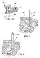
- FIG. 1shows a perspective diagram of a surgical retractor with rotating blades in accordance with an embodiment
- FIGS. 2A and. 2 Bshows perspective and cut away diagrams of a surgical retractor arm in accordance with an embodiment
- FIG. 2Cshows a cut away diagram of a surgical retractor arm in accordance with another embodiment
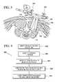
- FIG. 3shows an illustrated view of a dilator in the body of a patient in accordance with an embodiment
- FIG. 4shows an illustrated view of a further dilated area in the body of a patient in accordance with an embodiment
- FIG. 5shows an illustrated view of a surgical retractor with rotating blades used in the body of a patient in accordance with an embodiment
- FIG. 6shows a flow diagram of a method for using a surgical retractor in accordance with an embodiment
- FIG. 7shows a perspective diagram of a surgical retractor with rotating blades in accordance with another embodiment.
- a surgical retractorincludes a retractor body and retractor arms.
- the retractor armincludes a first portion attached to the retractor body and a second portion rotatably attached to the first portion.
- the second portionalso includes a connector for receiving a retractor blade.
- the second portionmay be attached to the first portion by a pivot pin and may rotate trough a range of motion of up to 90 degrees. However, when used in the body of a patient, a range of motion of up to about 45 degrees may be practical.
- the first portionmay includes a thumb screw in engagement with the second portion for forcing the second portion to rotate with respect to the first portion. Additionally, a spring may be located between the first and second portions in order to bias the second portion into a neutral position such that the retractor blades are generally parallel.
- a surgical retractor 100including a retractor body 102 .
- a first retractor armincluding a first portion 104 and a second portion 106 is connected to the retractor body 102 by the first portion 104 .
- the second portion 106is rotatably attached to the first portion 104 and includes at a distal end a connector 108 for receiving a retractor blade 110 .
- the connector 108may be configured in a variety of manners.
- One example of a connector for use with a surgical retractor bladeis described in U.S. application Ser. No. 11/219,847 by Daniel Bass and entitled “Connector for A Surgical Retractor”. This application is hereby incorporated by reference in its entirety.
- the retractor blade 110includes a proximal end 112 near the connector 108 and a distal end 114 which is inserted into the body of a patient.
- the second portion 106 which retains the retractor blade 110may rotate around an axis parallel to a line drawn along a length of the retractor arm. This rotation causes the distal end 114 of the retractor blade 110 to tilt or angle thus exposing a larger area inside the body of a patient without significantly increasing an insertion point. Because the distal end 114 of the retractor blade 110 moves through a larger range of motion than the proximal end 112 , the insertion point may be smaller than the area inside the body of the patient.
- the surgical retractor 100also includes a second retractor arm including a first portion 116 and a second portion 118 connected to the retractor body 102 by the first portion 116 .
- the second portion 118is rotatably attached to the first portion 116 and includes at a distal end a connector 120 for receiving a retractor blade 122 .
- the retractor blade 122includes a proximal end 124 near the connector 120 and a distal end 126 which is inserted into the body of a patient.
- the second portion 118 which retains the retractor blade 122may rotate around an axis parallel to a line drawn along a length of the retractor arm.
- This rotationcauses the distal end 126 of the retractor blade 122 to tilt or angle thus exposing a larger area inside the body of a patient without significantly increasing an insertion point. Because the distal end 126 of the retractor blade 122 moves through a larger range of motion than the proximal end 124 , the insertion point may be smaller than the area inside the body of the patient.
- the second portions 106 and 118 of the retractor armsmay be rotated. This causes the distal ends 114 and 126 to separate and expose a larger area inside the body of the patient than the area of the insertion point.
- the proximal ends 112 and 124 of the retractor blades 110 and 122may lie near the insertion point but may not significantly increase the insertion area as the proximal ends 112 and 124 move through a smaller range of motion than the distal ends 114 and 126 of the retractor blades 110 and 122 .
- FIG. 2Ashows a segment 200 of one of the retractor arms from FIG. 1 .
- the segment 200includes the first portion 104 and the second portion 106 of the retractor arm.
- the first portion 104 of the retractor armincludes a thumb screw 202 .
- the thumb screw 202screws into the first portion 104 and engages the second portion 106 .
- forceis exerted upon the second portion 106 causing rotation around an axis parallel to a line drawn along a length of the retractor arm.
- the thumb screw 202is loosened, the force is removed and the second portion 106 may rotate back to the original position.
- FIG. 2Bshows a cutaway view of the segment 200 along line B shown in FIG. 2A .
- the second portion 106is connected to the first portion 104 by a pivot pin 204 .
- a spring 206biases the second portion 106 into a neutral position.
- the neutral positionis a position wherein the retractor blade 110 is generally perpendicular to the retractor body 102 .
- the neutral positionis the position wherein the retractor blades 110 and 122 are generally parallel to one another.
- FIG. 2Cshows a cutaway view, of another example, of the segment 200 along line B shown in FIG. 2A .
- the second portion 106is connected to the first portion 104 by a pivot pin 204 .
- a spring 206biases the second portion 106 into a neutral position.
- the neutral positionis a position wherein the retractor blade 110 is generally perpendicular to the retractor body 102 .
- the neutral positionis the position wherein the retractor blades 110 and 122 are generally parallel to one another.
- the thumb screw 202in this example, includes a step-down end portion 210 with threads and an associated retaining nut 212 . Additionally, the second portion 106 includes an aperture. The step-down end portion 210 of the thumb screw 202 fits through the aperture while the remaining portion does not. The retaining nut 212 is then screwed onto the step-down end portion 210 thus locking the thumb screw 202 to the second portion 106 . In this arrangement, the thumb screw 202 is able to apply pressure to the second portion 106 forcing the second portion 106 into rotation to and from the neutral position. This example reduces the work required from the spring 206 .
- FIG. 3shows the body of a patient 300 .
- an opening 302is made in the body 300 .
- a dilator 304is then inserted.
- the opening 304is increase in diameter by inserting an additional dilator 306 . Any number of dilators may be inserted to increase the diameter of the opening 302 to a size for receiving the blades 110 and 122 of the retractor 100 .
- the blades 110 and 122 of the retractor 100are inserted into the opening 302 of the body.
- the thumb screws 202are adjusted to tilt the retractor blades 110 and 122 thus separating the distal ends 114 and 126 .
- a distal end 310 of the openingis larger in area than the proximal end 308 of the opening 302 . This allows the surgeon to perform work on the patient while reducing the incision size and the amount of trauma to the patient.
- FIG. 6shows a flow diagram of a method 600 for using the retractor 100 .
- the following description of the method 600is made with reference to the retractor 100 illustrated in FIG. 1 and patient 300 as shown in FIGS. 3-5 , and thus makes reference to the elements cited therein.
- the following description of the method 600is one manner in which the retractor 100 may be used. In this respect, it is to be understood that the following description of the method 600 is but one manner of a variety of different manners in which such a retractor may be used.
- an incisionis made in the body 300 of a patient at step 602 .
- a dilator 304is then inserted into the incision to create an opening 302 at step 604 .
- Additional dilators 306may also be inserted into the opening 302 to increase the size at step 606 .
- the blades 110 and 122 of the surgical retractor 100are inserted over the dilators 306 into the opening 302 and the dilators 304 and 306 are removed at step 608 .
- the thumb screws 202are then adjusted to increase the area near the distal end 310 of the opening 302 at step 610 . In this manner, the distal end 310 of the opening is increased without significantly increase the size of the proximal end 308 of the opening 302 in the body 300 .
- FIG. 7shows a surgical retractor 700 including a retractor body 702 .
- a first retractor arm including a first portion 704 and a second portion 706is connected to the retractor body 702 by the first portion 704 .
- the second portion 706is rotatably attached to the first portion 704 and includes at a distal end a connector 708 for receiving a retractor blade 710 .
- the connector 708may be configured in a variety of manners as described above in reference to FIG. 1 .
- the retractor blade 710includes a proximal end 712 near the connector 708 and a distal end 714 which is inserted into the body of a patient.
- the second portion 706 which retains the retractor blade 710may rotate around an axis parallel to a line drawn along a length of the retractor arm. This rotation causes the distal end 714 of the retractor blade 710 to tilt or angle thus exposing a larger area inside the body of a patient without significantly increasing an insertion point. Because the distal end 714 of the retractor blade 710 moves through a larger range of motion than the proximal end 712 , the insertion point may be smaller than the area inside the body of the patient.
- the surgical retractor 700also includes a second retractor arm including a first portion 716 and a second portion 718 connected to the retractor body 702 by the first portion 716 .
- the second portion 718is rotatably attached to the first portion 716 and includes at a distal end a connector 720 for receiving a retractor blade 722 .
- the retractor blade 722includes a proximal end 724 near the connector 720 and a distal end 726 which is inserted into the body of a patient.
- the second portion 718 which retains the retractor blade 722may rotate around an axis parallel to a line drawn along a length of the retractor arm.
- This rotationcauses the distal end 726 of the retractor blade 722 to tilt or angle thus exposing a larger area inside the body of a patient without significantly increasing an insertion point. Because the distal end 726 of the retractor blade 722 moves through a larger range of motion than the proximal end 724 , the insertion point may be smaller than the area inside the body of the patient.
- the surgical retractor 700also includes a third retractor arm including a first portion 728 and a second portion 730 connected to the retractor body 702 by the first portion 728 .
- the second portion 730is rotatably attached to the first portion 728 and includes at a distal end a connector 732 for receiving a retractor blade 734 .
- the retractor blade 734includes a proximal end 736 near the connector 732 and a distal end 738 which is inserted into the body of a patient.
- the second portion 730 which retains the retractor blade 734may rotate around an axis perpendicular to a line drawn along a length of the retractor arm.
- This rotationcauses the distal end 738 of the retractor blade 734 to tilt or angle thus exposing a larger area inside the body of a patient without significantly increasing an insertion point. Because the distal end 738 of the retractor blade 734 moves through a larger range of motion than the proximal end 736 , the insertion point may be smaller than the area inside the body of the patient.
- the second portions 706 , 718 , and 730 of the retractor armsmay be rotated. This causes the distal ends 714 , 726 , and 738 to separate and expose a larger area inside the body of the patient than the area of the insertion point.
- the proximal ends 712 , 724 , and 736 of the retractor blades 710 , 722 , and 734may lie near the insertion point but may not significantly increase the insertion area as the proximal ends 712 , 724 , and 736 move through a smaller range of motion than the distal ends 714 , 726 , and 738 of the retractor blades 710 , 722 , and 734 .
Landscapes
- Health & Medical Sciences (AREA)
- Life Sciences & Earth Sciences (AREA)
- Surgery (AREA)
- Heart & Thoracic Surgery (AREA)
- Engineering & Computer Science (AREA)
- Biomedical Technology (AREA)
- Nuclear Medicine, Radiotherapy & Molecular Imaging (AREA)
- Medical Informatics (AREA)
- Molecular Biology (AREA)
- Animal Behavior & Ethology (AREA)
- General Health & Medical Sciences (AREA)
- Public Health (AREA)
- Veterinary Medicine (AREA)
- Surgical Instruments (AREA)
Abstract
Description
This application claims the benefit of U.S. Provisional Patent Application No. 60/720,485, filed Sep. 27, 2005, and entitled, “Surgical Retractor With Rotating Blades.”
Surgical procedures often require the creation of a surgical exposure to allow a surgeon to reach deeper regions of the body. The surgical exposure is usually started with an incision of a suitable depth. Surgical instruments known as retractors are then inserted into the incision and used to pull back skin, muscle and other soft tissue to permit access to the desired area.
A typical retractor is made up of a retractor body attached to one or more retractor blades. Retractor blades are smooth, thin plates with dull edges that are inserted into the incision to pull back the tissue. Retractor blades come in many different sizes depending on the particular application and physical characteristics of the patient. Retractor blades may be slightly curved or completely flat and may have end prongs of various configurations to make it easier to pull back tissue. The retractor blades can be attached to a wide variety of retractor bodies, such as for hand-held and self-retaining retractors.
Hand-held retractors are made up of a simple grip attached to a retractor blade. The retractor blade may be fixed or interchangeable. The retractor blade is inserted into the incision and then the grip is used to pull back the blade to create the surgical exposure. The grip may be attached at an angle to the retractor blade to make it easier to pull back on the blade. Hand-held retractors must be held in place by hand in order to maintain the surgical exposure.
Self-retaining retractors have specialized retractor bodies that allow them to maintain a surgical exposure without needing to be held in place by hand. Two common self-retaining retractors are longitudinal retractors and transverse retractors.
Longitudinal retractors have a retractor body made up of two seesawing arms with a pair of opposed retractor blades on their respective ends. The retractor body typically has a ratcheting mechanism to lock apart the two opposed retractor blades and hold them in place. This maintains the surgical exposure without the need for the retractor to be held in place by hand. The two arms may be hinged to facilitate access to the retraction site. The retractor blades may be either fixed or interchangeable.
Transverse retractors have a retractor body made up of a transverse rack with a fixed arm and a sliding arm. The fixed arm and sliding arm have opposed retractor blades on their respective ends. The sliding arm typically has a turnkey that operates a ratcheting mechanism, which ratchets the sliding arm away from the fixed arm and locks apart the retractor blades. The two arms may be hinged to facilitate access to the retraction site. The retractor blades may be either fixed or interchangeable.
The retractors in use today retract the opening created in the body of the patient in a uniform manner. If the surgeon needs a large opening near the spine, for instance, the opening in the body of the patient must be retracted in a uniform manner. This creates significant trauma for the patient and increases the patient's recovery time.
What is needed is a surgical retractor that gives a surgeon a suitable area within the body to work on the patient while reducing the required incision size. This reduces trauma to the patient and reduces the patient's recovery time.
According to an embodiment, a surgical retractor includes a retractor body and a retractor arm. The retractor arm includes a first portion and a second portion. The first portion is attached to the retractor body and the second portion is rotatably attached to the first portion. The second portion is configured to retain a retractor blade and to rotate about an axis parallel to a line drawn along a length of the retractor arm.
Examples of the invention are illustrated, without limitation, in the accompanying figures in which like numeral references refer to like elements and wherein:
For simplicity and illustrative purposes, the principles are shown by way of examples of systems and methods described. In the following description, numerous specific details are set forth in order to provide a thorough understanding of the examples. It will be apparent however, to one of ordinary skill in the art, that the examples may be practiced without limitation to these specific details. In other instances, well known methods and structures are not described in detail so as not to unnecessarily obscure understanding of the examples.
In an example, a surgical retractor includes a retractor body and retractor arms. The retractor arm includes a first portion attached to the retractor body and a second portion rotatably attached to the first portion. The second portion also includes a connector for receiving a retractor blade. The second portion may be attached to the first portion by a pivot pin and may rotate trough a range of motion of up to 90 degrees. However, when used in the body of a patient, a range of motion of up to about 45 degrees may be practical. The first portion may includes a thumb screw in engagement with the second portion for forcing the second portion to rotate with respect to the first portion. Additionally, a spring may be located between the first and second portions in order to bias the second portion into a neutral position such that the retractor blades are generally parallel.
With reference first to FIG1, there is shown asurgical retractor 100 including aretractor body 102. A first retractor arm including afirst portion 104 and asecond portion 106 is connected to theretractor body 102 by thefirst portion 104. Thesecond portion 106 is rotatably attached to thefirst portion 104 and includes at a distal end aconnector 108 for receiving aretractor blade 110. Theconnector 108 may be configured in a variety of manners. One example of a connector for use with a surgical retractor blade is described in U.S. application Ser. No. 11/219,847 by Daniel Bass and entitled “Connector for A Surgical Retractor”. This application is hereby incorporated by reference in its entirety.
Theretractor blade 110 includes aproximal end 112 near theconnector 108 and adistal end 114 which is inserted into the body of a patient. Thesecond portion 106 which retains theretractor blade 110 may rotate around an axis parallel to a line drawn along a length of the retractor arm. This rotation causes thedistal end 114 of theretractor blade 110 to tilt or angle thus exposing a larger area inside the body of a patient without significantly increasing an insertion point. Because thedistal end 114 of theretractor blade 110 moves through a larger range of motion than theproximal end 112, the insertion point may be smaller than the area inside the body of the patient.
Thesurgical retractor 100 also includes a second retractor arm including afirst portion 116 and asecond portion 118 connected to theretractor body 102 by thefirst portion 116. Thesecond portion 118 is rotatably attached to thefirst portion 116 and includes at a distal end aconnector 120 for receiving aretractor blade 122. Theretractor blade 122 includes aproximal end 124 near theconnector 120 and adistal end 126 which is inserted into the body of a patient. Thesecond portion 118 which retains theretractor blade 122 may rotate around an axis parallel to a line drawn along a length of the retractor arm. This rotation causes thedistal end 126 of theretractor blade 122 to tilt or angle thus exposing a larger area inside the body of a patient without significantly increasing an insertion point. Because thedistal end 126 of theretractor blade 122 moves through a larger range of motion than theproximal end 124, the insertion point may be smaller than the area inside the body of the patient.
When theretractor blades second portions retractor blades retractor blades
InFIG. 5 , theblades retractor 100 are inserted into theopening 302 of the body. The thumb screws202 are adjusted to tilt theretractor blades distal end 310 of the opening is larger in area than theproximal end 308 of theopening 302. This allows the surgeon to perform work on the patient while reducing the incision size and the amount of trauma to the patient.
In themethod 600, an incision is made in thebody 300 of a patient atstep 602. Adilator 304 is then inserted into the incision to create anopening 302 atstep 604.Additional dilators 306 may also be inserted into theopening 302 to increase the size atstep 606. Theblades surgical retractor 100 are inserted over thedilators 306 into theopening 302 and thedilators step 608. The thumb screws202 are then adjusted to increase the area near thedistal end 310 of theopening 302 atstep 610. In this manner, thedistal end 310 of the opening is increased without significantly increase the size of theproximal end 308 of theopening 302 in thebody 300.
Theretractor blade 710 includes aproximal end 712 near theconnector 708 and adistal end 714 which is inserted into the body of a patient. Thesecond portion 706 which retains theretractor blade 710 may rotate around an axis parallel to a line drawn along a length of the retractor arm. This rotation causes thedistal end 714 of theretractor blade 710 to tilt or angle thus exposing a larger area inside the body of a patient without significantly increasing an insertion point. Because thedistal end 714 of theretractor blade 710 moves through a larger range of motion than theproximal end 712, the insertion point may be smaller than the area inside the body of the patient.
Thesurgical retractor 700 also includes a second retractor arm including afirst portion 716 and asecond portion 718 connected to theretractor body 702 by thefirst portion 716. Thesecond portion 718 is rotatably attached to thefirst portion 716 and includes at a distal end aconnector 720 for receiving aretractor blade 722. Theretractor blade 722 includes aproximal end 724 near theconnector 720 and adistal end 726 which is inserted into the body of a patient. Thesecond portion 718 which retains theretractor blade 722 may rotate around an axis parallel to a line drawn along a length of the retractor arm. This rotation causes thedistal end 726 of theretractor blade 722 to tilt or angle thus exposing a larger area inside the body of a patient without significantly increasing an insertion point. Because thedistal end 726 of theretractor blade 722 moves through a larger range of motion than theproximal end 724, the insertion point may be smaller than the area inside the body of the patient.
Thesurgical retractor 700 also includes a third retractor arm including afirst portion 728 and asecond portion 730 connected to theretractor body 702 by thefirst portion 728. Thesecond portion 730 is rotatably attached to thefirst portion 728 and includes at a distal end aconnector 732 for receiving aretractor blade 734. Theretractor blade 734 includes aproximal end 736 near theconnector 732 and adistal end 738 which is inserted into the body of a patient. Thesecond portion 730 which retains theretractor blade 734 may rotate around an axis perpendicular to a line drawn along a length of the retractor arm. This rotation causes thedistal end 738 of theretractor blade 734 to tilt or angle thus exposing a larger area inside the body of a patient without significantly increasing an insertion point. Because thedistal end 738 of theretractor blade 734 moves through a larger range of motion than theproximal end 736, the insertion point may be smaller than the area inside the body of the patient.
When theretractor blades second portions retractor blades retractor blades
What has been described and illustrated herein are examples of the systems and methods described herein along with some of their variations. The terms, descriptions and figures used herein are set forth by way of illustration only and are not meant as limitations. Those skilled in the art will recognize that many variations are possible within the spirit and scope of these examples, which are intended to be defined by the following claims and their equivalents in which all terms are meant in their broadest reasonable sense unless otherwise indicated.
Claims (12)
1. A surgical retractor comprising:
a retractor body;
a first retractor arm having a first portion and a second portion, the first portion attached to the retractor body and the second portion rotatably attached to the first portion and configured to retain a first retractor blade, wherein the second portion rotates about an axis parallel to a line drawn along a length of the first retractor arm;
a second retractor arm having a third portion and a fourth portion, the third portion attached to the retractor body and the fourth portion rotatably attached to the third portion and configured to retain a second retractor blade, wherein the fourth portion rotates about an axis parallel to a line drawn along a length of the second retractor arm;
a third retractor arm having a fifth portion and a sixth portion, the fifth portion attached to the retractor body and the sixth portion rotatably attached to the fifth portion and configured to retain a third retractor blade, wherein the sixth portion rotates about an axis perpendicular to a line drawn along a length of the third retractor arm; and
a spring located between the first and second portions, the spring biasing the second portion into a position such that the first retractor blade is substantially normal to a line drawn parallel to the first portion of the first retractor arm.
2. The surgical retractor ofclaim 1 , wherein the second portion may rotate through a range of motion of about 90 degrees.
3. The surgical retractor ofclaim 2 , wherein the second portion may rotate through a range of motion of about 45 degrees.
4. The surgical retractor ofclaim 1 , further comprising:
a pivot pin for connecting the second portion to the first portion.
5. The surgical retractor ofclaim 4 , further comprising:
a thumb screw mounted on the first portion of the first retractor arm and in contact with the second portion of the first retractor arm, such that, adjustment of the thumb screw causes rotation of the second portion of the first retractor arm.
6. The surgical retractor ofclaim 5 , wherein the second portion of the first retractor arm includes an aperture and wherein the thumb screw includes an end portion attached to the second portion through the aperture.
7. A surgical retractor comprising:
a retractor assembly;
a first retractor arm having a first portion and a second portion, the first portion attached to the retractor assembly;
a second retractor arm having a third portion and a fourth portion, the third portion attached to the retractor assembly;
a third retractor arm having a fifth portion and a sixth portion, the fifth portion attached to the retractor assembly;
means for rotatably attaching the sixth portion of the third retractor arm to the fifth portion, wherein the second portion and the sixth portion rotate about non-parallel axes;
means for rotatably attaching the second portion of the first retractor arm to the first portion; and
means for biasing the second portion of the first retractor arm in a first position.
8. The surgical retractor ofclaim 7 , further comprising:
means for rotating the second portion of the first retractor arm to a second position.
9. The surgical retractor ofclaim 8 ,
wherein the second portion of the first retractor arm comprises means for retaining a retractor blade,
wherein, in the first position, the retractor blade is generally normal to a line parallel with the retractor assembly, and
wherein, in the second position, the retractor blade is angled with respect to the line parallel with the retractor assembly.
10. A method of using a surgical retractor comprising:
creating an opening in a body of a patient, the opening having a proximal end near the skin of the patient and a distal end further inside the body of the patient;
providing a surgical retractor including three retractor arms,
a first retractor arm having a first portion and a second portion rotatably attached to the first portion, the second portion retaining a first retractor blade, wherein the second portion rotates about an axis parallel to a line drawn along a length of the first retractor arm,
a second retractor arm having a third portion and a fourth portion rotatably attached to the third portion, the fourth portion retaining a second retractor blade, wherein the fourth portion rotates about an axis parallel to a line drawn along a length of the second retractor arm, and
a third retractor arm having a fifth portion and a sixth portion rotatably attached to the fifth portion, the sixth portion retaining a third retractor blade and rotating about an axis perpendicular to a line drawn along a length of the third retractor arm,
wherein each retractor blade has a proximal end and a distal end;
inserting the first, second, and third retractor blades within the opening;
rotating the second portion of the first retractor arm, the fourth portion of the second retractor arm, and the sixth portion of the third retractor arm so that distal ends of the first, second, and third retractor blades enlarge the distal end of the opening without substantially increasing the proximal end of the opening; and
biasing at least one of the second portion of the first retractor arm, the fourth portion of the second retractor arm, and the sixth portion of the third retractor arm in a first position.
11. The method ofclaim 10 , further comprising:
adjusting a thumb screw to rotate at least one of the first portion of the first retractor arm, the third portion of the second retractor arm, and the fifth portion of the third retractor arm.
12. The method ofclaim 10 , further comprising:
creating an incision in the body of the patient;
inserting a dilator through the incision for creating the opening; and
dilating the opening to a size for receiving the first, second, and third retractor blades.
Priority Applications (1)
| Application Number | Priority Date | Filing Date | Title |
|---|---|---|---|
| US11/353,128US7537565B2 (en) | 2005-09-27 | 2006-02-14 | Surgical retractor with rotating blades |
Applications Claiming Priority (2)
| Application Number | Priority Date | Filing Date | Title |
|---|---|---|---|
| US72048505P | 2005-09-27 | 2005-09-27 | |
| US11/353,128US7537565B2 (en) | 2005-09-27 | 2006-02-14 | Surgical retractor with rotating blades |
Publications (2)
| Publication Number | Publication Date |
|---|---|
| US20070073111A1 US20070073111A1 (en) | 2007-03-29 |
| US7537565B2true US7537565B2 (en) | 2009-05-26 |
Family
ID=37895021
Family Applications (1)
| Application Number | Title | Priority Date | Filing Date |
|---|---|---|---|
| US11/353,128Active2026-07-27US7537565B2 (en) | 2005-09-27 | 2006-02-14 | Surgical retractor with rotating blades |
Country Status (1)
| Country | Link |
|---|---|
| US (1) | US7537565B2 (en) |
Cited By (89)
| Publication number | Priority date | Publication date | Assignee | Title |
|---|---|---|---|---|
| US20080249372A1 (en)* | 2007-03-30 | 2008-10-09 | Joey Camia Reglos | Retractor |
| US20090156902A1 (en)* | 2002-06-26 | 2009-06-18 | Jonathan Dewey | Instruments and methods for minimally invasive tissue retraction and surgery |
| US20100113885A1 (en)* | 2008-10-30 | 2010-05-06 | Warsaw Orthopedic, Inc. | Retractor assemblies for surgery in a patient |
| US20110172494A1 (en)* | 2010-01-12 | 2011-07-14 | Tedan Surgical | Surgical retractor with curved rotating blades |
| US20110224496A1 (en)* | 2010-03-11 | 2011-09-15 | Mark Weiman | Tissue Retractor and Method of Use |
| US20110224497A1 (en)* | 2010-03-11 | 2011-09-15 | Mark Weiman | Tissue Retractor and Methods Of Use |
| US20120041272A1 (en)* | 2010-08-16 | 2012-02-16 | Dietze Jr Donald David | Surgical instrument system and method for providing retraction and vertebral distraction |
| US20120271118A1 (en)* | 2011-04-19 | 2012-10-25 | NSI-US, Inc. | Quick-release handle for retractor blades |
| US8357184B2 (en) | 2009-11-10 | 2013-01-22 | Nuvasive, Inc. | Method and apparatus for performing spinal surgery |
| US20130225935A1 (en)* | 2010-10-08 | 2013-08-29 | K2M, Inc. | Lateral access system and method of use |
| US20130261401A1 (en)* | 2012-03-30 | 2013-10-03 | Depuy Spine, Inc. | Methods and Devices for Tissue Retraction |
| US8636655B1 (en) | 2010-01-19 | 2014-01-28 | Ronald Childs | Tissue retraction system and related methods |
| US20140114139A1 (en)* | 2012-10-24 | 2014-04-24 | Blackstone Medical, Inc. | Retractor device and method |
| US8888694B2 (en)* | 2008-11-21 | 2014-11-18 | N.B.R. New Biotechnology Research | Surgical instrument and method for operations on the spinal column |
| US8900137B1 (en) | 2011-04-26 | 2014-12-02 | Nuvasive, Inc. | Cervical retractor |
| US20140371540A1 (en)* | 2006-09-22 | 2014-12-18 | Alphatec Spine, Inc. | Retractor |
| US8974381B1 (en) | 2011-04-26 | 2015-03-10 | Nuvasive, Inc. | Cervical retractor |
| US9066701B1 (en) | 2012-02-06 | 2015-06-30 | Nuvasive, Inc. | Systems and methods for performing neurophysiologic monitoring during spine surgery |
| US9084591B2 (en) | 2012-10-23 | 2015-07-21 | Neurostructures, Inc. | Retractor |
| US9113853B1 (en) | 2011-08-31 | 2015-08-25 | Nuvasive, Inc. | Systems and methods for performing spine surgery |
| US20150272694A1 (en)* | 2012-06-27 | 2015-10-01 | CamPlex LLC | Surgical visualization system |
| US9179903B2 (en) | 2010-03-11 | 2015-11-10 | Globus Medical, Inc. | Tissue retractor and method of use |
| US9307972B2 (en) | 2011-05-10 | 2016-04-12 | Nuvasive, Inc. | Method and apparatus for performing spinal fusion surgery |
| US9486133B2 (en) | 2010-08-23 | 2016-11-08 | Nuvasive, Inc. | Surgical access system and related methods |
| US9492065B2 (en) | 2012-06-27 | 2016-11-15 | Camplex, Inc. | Surgical retractor with video cameras |
| US9655505B1 (en) | 2012-02-06 | 2017-05-23 | Nuvasive, Inc. | Systems and methods for performing neurophysiologic monitoring during spine surgery |
| US9675389B2 (en) | 2009-12-07 | 2017-06-13 | Samy Abdou | Devices and methods for minimally invasive spinal stabilization and instrumentation |
| US9693761B2 (en) | 2012-10-24 | 2017-07-04 | Blackstone Medical, Inc. | Retractor device and method |
| US9757067B1 (en) | 2012-11-09 | 2017-09-12 | Nuvasive, Inc. | Systems and methods for performing neurophysiologic monitoring during spine surgery |
| US9782159B2 (en) | 2013-03-13 | 2017-10-10 | Camplex, Inc. | Surgical visualization systems |
| US9795370B2 (en) | 2014-08-13 | 2017-10-24 | Nuvasive, Inc. | Minimally disruptive retractor and associated methods for spinal surgery |
| US9795367B1 (en) | 2003-10-17 | 2017-10-24 | Nuvasive, Inc. | Surgical access system and related methods |
| US20180110505A1 (en)* | 2016-10-26 | 2018-04-26 | Thompson Surgical Instruments, Inc. | Adaptor handle for surgical retractor |
| US9955959B2 (en) | 2014-03-05 | 2018-05-01 | Boss Instruments, Ltd | Rotating retractor arm |
| US10028651B2 (en) | 2013-09-20 | 2018-07-24 | Camplex, Inc. | Surgical visualization systems and displays |
| WO2018165163A1 (en) | 2017-03-06 | 2018-09-13 | Tedan Surgical Innovations, Llc | Surgical retractor with a locking retractor blade |
| US20180338752A1 (en)* | 2014-01-24 | 2018-11-29 | David S. Ruppert | Retraction devices and methods of its use and manufacture |
| US10213192B2 (en) | 2015-07-15 | 2019-02-26 | Warsaw Orthopedic, Inc. | Surgical instrument and method of use |
| US10219798B2 (en) | 2015-07-15 | 2019-03-05 | Warsaw Orthopedic, Inc. | Surgical instrument and method of use |
| US20190083081A1 (en)* | 2016-03-09 | 2019-03-21 | Spinal Elements, Inc. | Retractor |
| US10548740B1 (en) | 2016-10-25 | 2020-02-04 | Samy Abdou | Devices and methods for vertebral bone realignment |
| US10568499B2 (en) | 2013-09-20 | 2020-02-25 | Camplex, Inc. | Surgical visualization systems and displays |
| US10575961B1 (en) | 2011-09-23 | 2020-03-03 | Samy Abdou | Spinal fixation devices and methods of use |
| US10695105B2 (en) | 2012-08-28 | 2020-06-30 | Samy Abdou | Spinal fixation devices and methods of use |
| US10702353B2 (en) | 2014-12-05 | 2020-07-07 | Camplex, Inc. | Surgical visualizations systems and displays |
| US10799226B2 (en) | 2015-07-15 | 2020-10-13 | Warsaw Orthopedic, Inc. | Surgical adaptor and method |
| US10857003B1 (en) | 2015-10-14 | 2020-12-08 | Samy Abdou | Devices and methods for vertebral stabilization |
| US10898174B2 (en) | 2013-03-11 | 2021-01-26 | Spinal Elements, Inc. | Method of using a surgical tissue retractor |
| US10918498B2 (en) | 2004-11-24 | 2021-02-16 | Samy Abdou | Devices and methods for inter-vertebral orthopedic device placement |
| US10918455B2 (en) | 2017-05-08 | 2021-02-16 | Camplex, Inc. | Variable light source |
| US10966798B2 (en) | 2015-11-25 | 2021-04-06 | Camplex, Inc. | Surgical visualization systems and displays |
| US10973648B1 (en) | 2016-10-25 | 2021-04-13 | Samy Abdou | Devices and methods for vertebral bone realignment |
| US11006982B2 (en) | 2012-02-22 | 2021-05-18 | Samy Abdou | Spinous process fixation devices and methods of use |
| US11154378B2 (en) | 2015-03-25 | 2021-10-26 | Camplex, Inc. | Surgical visualization systems and displays |
| US11173040B2 (en) | 2012-10-22 | 2021-11-16 | Cogent Spine, LLC | Devices and methods for spinal stabilization and instrumentation |
| US11179146B2 (en) | 2014-09-10 | 2021-11-23 | Spinal Elements, Inc. | Retractor |
| US11179248B2 (en) | 2018-10-02 | 2021-11-23 | Samy Abdou | Devices and methods for spinal implantation |
| US11224415B1 (en) | 2020-07-10 | 2022-01-18 | Warsaw Orthopedic, Inc. | Tissue retractor |
| US11285014B1 (en) | 2020-11-05 | 2022-03-29 | Warsaw Orthopedic, Inc. | Expandable inter-body device, system, and method |
| US11291554B1 (en) | 2021-05-03 | 2022-04-05 | Medtronic, Inc. | Unibody dual expanding interbody implant |
| USD956224S1 (en) | 2020-05-12 | 2022-06-28 | Innovasis, Inc. | Surgical retractor |
| USD956225S1 (en) | 2020-05-12 | 2022-06-28 | Innovasis, Inc. | Surgical retractor |
| USD956223S1 (en) | 2020-05-12 | 2022-06-28 | Innovasis, Inc. | Surgical retractor |
| US11376134B1 (en) | 2020-11-05 | 2022-07-05 | Warsaw Orthopedic, Inc. | Dual expanding spinal implant, system, and method of use |
| US11395743B1 (en) | 2021-05-04 | 2022-07-26 | Warsaw Orthopedic, Inc. | Externally driven expandable interbody and related methods |
| US11432810B2 (en) | 2020-05-12 | 2022-09-06 | Innovasis, Inc. | Systems and methods for surgical retraction |
| US11517443B2 (en) | 2020-11-05 | 2022-12-06 | Warsaw Orthopedic, Inc. | Dual wedge expandable implant, system and method of use |
| US11564724B2 (en) | 2020-11-05 | 2023-01-31 | Warsaw Orthopedic, Inc. | Expandable inter-body device, system and method |
| US11612499B2 (en) | 2021-06-24 | 2023-03-28 | Warsaw Orthopedic, Inc. | Expandable interbody implant |
| US11638653B2 (en) | 2020-11-05 | 2023-05-02 | Warsaw Orthopedic, Inc. | Surgery instruments with a movable handle |
| US11730608B2 (en) | 2021-07-13 | 2023-08-22 | Warsaw Orthopedic, Inc. | Monoblock expandable interbody implant |
| US11793504B2 (en) | 2011-08-19 | 2023-10-24 | Nuvasive, Inc. | Surgical retractor system and methods of use |
| US11806250B2 (en) | 2018-02-22 | 2023-11-07 | Warsaw Orthopedic, Inc. | Expandable spinal implant system and method of using same |
| US11833059B2 (en) | 2020-11-05 | 2023-12-05 | Warsaw Orthopedic, Inc. | Expandable inter-body device, expandable plate system, and associated methods |
| US11850163B2 (en) | 2022-02-01 | 2023-12-26 | Warsaw Orthopedic, Inc. | Interbody implant with adjusting shims |
| US11963881B2 (en) | 2020-11-05 | 2024-04-23 | Warsaw Orthopedic, Inc. | Expandable inter-body device, system, and method |
| US11998184B2 (en) | 2010-03-11 | 2024-06-04 | Globus Medical, Inc | Tissue retractor and methods of use |
| US12096923B2 (en) | 2020-07-10 | 2024-09-24 | Warsaw Orthopedic, Inc. | Tissue retractor, retraction modules, and associated methods |
| US12121453B2 (en) | 2020-11-05 | 2024-10-22 | Warsaw Orthopedic, Inc. | Dual wedge expandable implant with eyelets, system, and method of use |
| US12171439B2 (en) | 2020-11-05 | 2024-12-24 | Warsaw Orthopedic, Inc. | Protected drill |
| US12239544B2 (en) | 2020-11-05 | 2025-03-04 | Warsaw Orthopedic, Inc. | Rhomboid shaped implants |
| US12268614B2 (en) | 2021-06-24 | 2025-04-08 | Warsaw Orthopedic, Inc. | Interbody implant with adjusting shims |
| US12295865B2 (en) | 2021-06-24 | 2025-05-13 | Warsaw Orthopedic, Inc. | Expandable interbody implant and corresponding inserter |
| US12295624B2 (en) | 2022-05-24 | 2025-05-13 | Globus Medical, Inc. | TLIF distraction and retraction |
| US12318308B2 (en) | 2020-11-05 | 2025-06-03 | Warsaw Orthopedic, Inc. | Dual expandable inter-body device |
| US12349889B2 (en) | 2020-07-10 | 2025-07-08 | Warsaw Orthopedic, Inc. | Tissue retractor, retraction modules, and associated methods |
| US12383249B2 (en) | 2020-07-10 | 2025-08-12 | Warsaw Orthopedic, Inc. | Tissue retractor, retraction modules, and associated methods |
| US12414863B2 (en) | 2021-06-24 | 2025-09-16 | Warsaw Orthopedic, Inc. | Expandable interbody implant and corresponding surgical tool |
| US12440349B2 (en) | 2022-02-04 | 2025-10-14 | Warsaw Orthopedic, Inc. | Expandable interbody implant and breakoff screw |
Families Citing this family (33)
| Publication number | Priority date | Publication date | Assignee | Title |
|---|---|---|---|---|
| US8876687B2 (en)* | 2006-03-08 | 2014-11-04 | Zimmer Spine, Inc. | Surgical retractor and retractor assembly |
| US7985221B2 (en)* | 2006-04-20 | 2011-07-26 | Millennium Medical Technologies, Inc. | External fixator |
| US8142355B2 (en)* | 2006-09-25 | 2012-03-27 | Spinal Elements, Inc. | Surgical tissue retractor |
| US7922658B2 (en)* | 2006-11-09 | 2011-04-12 | Ebi, Llc | Surgical retractor device and related methods |
| US7931589B2 (en)* | 2006-11-09 | 2011-04-26 | Ebi, Llc | Surgical retractor device and related methods |
| BRPI0818608A2 (en) | 2007-10-05 | 2015-04-22 | Synthes Gmbh | Sequential directional dilatation system for dilating from a nerve of a patient's anatomy, and method for forming an access opening through a psoas muscle to a patient's spine using a dilatation system |
| US8114016B2 (en)* | 2008-03-04 | 2012-02-14 | GoMedica Technologies Co., Ltd. | Modular surgery retractor system |
| US9060757B2 (en)* | 2008-05-05 | 2015-06-23 | Ranier Limited | Distractor |
| US8211012B2 (en)* | 2008-09-30 | 2012-07-03 | Aesculap Implant Systems, Llc | Tissue retractor system |
| USD626223S1 (en) | 2008-10-22 | 2010-10-26 | Ebi, Llc | Tip portion of a surgical retractor blade |
| DE102009018139A1 (en)* | 2009-04-16 | 2010-10-21 | Aesculap Ag | Surgical retraction device |
| DE202009009503U1 (en)* | 2009-07-11 | 2009-09-10 | Gottfried Storz Medizintechnik Gmbh & Co. Kg | Surgical spreader instrument |
| WO2012040206A1 (en)* | 2010-09-20 | 2012-03-29 | Synthes Usa, Llc | Spinal access retractor |
| EP2750611B1 (en) | 2011-08-31 | 2016-11-23 | Lanx, Inc. | Lateral retractor system |
| EP2747670A4 (en)* | 2011-10-05 | 2015-06-24 | Mark A Dodson | Modular retractor and related method |
| US9808232B2 (en) | 2011-11-01 | 2017-11-07 | DePuy Synthes Products, Inc. | Dilation system |
| US9265490B2 (en) | 2012-04-16 | 2016-02-23 | DePuy Synthes Products, Inc. | Detachable dilator blade |
| US10835228B2 (en)* | 2012-07-17 | 2020-11-17 | Warsaw Orthopedic, Inc. | Surgical retractor and method of use |
| KR101298059B1 (en) | 2013-02-04 | 2013-08-20 | 순천향대학교 산학협력단 | Muscle retractor |
| US10278786B2 (en) | 2014-02-18 | 2019-05-07 | Globus Medical, Inc. | Retracting tissue |
| US10039539B2 (en) | 2014-02-18 | 2018-08-07 | Globus Medical, Inc. | Retracting tissue |
| US10285680B2 (en) | 2014-02-18 | 2019-05-14 | Globus Medical, Inc. | Retracting tissue |
| CN106793940B (en)* | 2015-08-06 | 2019-02-12 | 纽文思公司 | Minimally invasive retractor and associated method for spine surgery |
| CN105769262B (en)* | 2016-01-25 | 2018-02-09 | 许加友 | A kind of gastrointestinal surgery assistive device |
| CN108577909A (en)* | 2018-05-18 | 2018-09-28 | 山西大医院(山西医学科学院) | A kind of operation on vertebra channel system |
| CN110403711B (en)* | 2019-07-29 | 2022-03-29 | 孙彬 | Chest supports fixing device for cardiovascular internal medicine operation |
| US11517298B2 (en)* | 2019-08-14 | 2022-12-06 | Lsi Solutions, Inc. | Surgical rib retractor |
| US11944286B2 (en)* | 2020-01-24 | 2024-04-02 | Lsi Solutions, Inc. | Surgical rib retractor |
| CN111281448B (en)* | 2020-02-07 | 2021-07-13 | 青岛大学附属医院 | An auxiliary instrument for gastrointestinal surgery |
| CN111166402A (en)* | 2020-03-06 | 2020-05-19 | 中国医学科学院北京协和医院 | Endoscope breast augmentation retractor |
| KR102188043B1 (en)* | 2020-05-06 | 2020-12-07 | 유앤아이 주식회사 | A surgical retractor |
| US12185987B2 (en)* | 2020-10-02 | 2025-01-07 | Atlas Spine, Inc. | Bone anchor based retractor/distractor |
| US20220133292A1 (en)* | 2020-11-04 | 2022-05-05 | Spineology Inc. | Surgical retractor |
Citations (18)
| Publication number | Priority date | Publication date | Assignee | Title |
|---|---|---|---|---|
| US497064A (en)* | 1893-05-09 | Speculum | ||
| US1706500A (en)* | 1927-08-01 | 1929-03-26 | Henry J Smith | Surgical retractor |
| US2642862A (en)* | 1952-02-25 | 1953-06-23 | Henry M Jackson | Surgical retractor |
| US4263899A (en) | 1978-05-01 | 1981-04-28 | Burgin Kermit H | Locking adjustable speculum |
| US4852552A (en)* | 1987-09-03 | 1989-08-01 | Pilling Co. | Sternal retractor |
| US5052373A (en)* | 1988-07-29 | 1991-10-01 | Michelson Gary K | Spinal retractor |
| US5512038A (en) | 1993-11-15 | 1996-04-30 | O'neal; Darrell D. | Spinal retractor apparatus having a curved blade |
| US5813978A (en) | 1994-07-19 | 1998-09-29 | Atlantis Surgical, Inc. | Method and apparatus for direct access endoscopic surgery |
| US5846193A (en)* | 1997-05-01 | 1998-12-08 | Wright; John T. M. | Midcab retractor |
| US5902233A (en) | 1996-12-13 | 1999-05-11 | Thompson Surgical Instruments, Inc. | Angling surgical retractor apparatus and method of retracting anatomy |
| US5931777A (en) | 1998-03-11 | 1999-08-03 | Sava; Gerard A. | Tissue retractor and method for use |
| US5944658A (en)* | 1997-09-23 | 1999-08-31 | Koros; Tibor B. | Lumbar spinal fusion retractor and distractor system |
| US6206828B1 (en)* | 1999-06-08 | 2001-03-27 | John T. M. Wright | Sternal retractor with changeable blades and blade latch mechanism |
| US20010041828A1 (en)* | 1997-05-02 | 2001-11-15 | Jens E. Hoekendijk | Surgical retractor |
| US6572540B2 (en) | 2001-05-24 | 2003-06-03 | Minnesota Scientific, Inc. | Cam-wedge locking mechanism |
| US6663562B2 (en) | 2001-09-14 | 2003-12-16 | David Chang | Surgical retractor |
| US20040002629A1 (en)* | 2002-06-26 | 2004-01-01 | Branch Charles L. | Instruments and methods for minimally invasive tissue retraction and surgery |
| US7147599B2 (en)* | 2002-07-03 | 2006-12-12 | Boss Instruments, Ltd., Inc. | Surgical retractor with improved arms |
- 2006
- 2006-02-14USUS11/353,128patent/US7537565B2/enactiveActive
Patent Citations (18)
| Publication number | Priority date | Publication date | Assignee | Title |
|---|---|---|---|---|
| US497064A (en)* | 1893-05-09 | Speculum | ||
| US1706500A (en)* | 1927-08-01 | 1929-03-26 | Henry J Smith | Surgical retractor |
| US2642862A (en)* | 1952-02-25 | 1953-06-23 | Henry M Jackson | Surgical retractor |
| US4263899A (en) | 1978-05-01 | 1981-04-28 | Burgin Kermit H | Locking adjustable speculum |
| US4852552A (en)* | 1987-09-03 | 1989-08-01 | Pilling Co. | Sternal retractor |
| US5052373A (en)* | 1988-07-29 | 1991-10-01 | Michelson Gary K | Spinal retractor |
| US5512038A (en) | 1993-11-15 | 1996-04-30 | O'neal; Darrell D. | Spinal retractor apparatus having a curved blade |
| US5813978A (en) | 1994-07-19 | 1998-09-29 | Atlantis Surgical, Inc. | Method and apparatus for direct access endoscopic surgery |
| US5902233A (en) | 1996-12-13 | 1999-05-11 | Thompson Surgical Instruments, Inc. | Angling surgical retractor apparatus and method of retracting anatomy |
| US5846193A (en)* | 1997-05-01 | 1998-12-08 | Wright; John T. M. | Midcab retractor |
| US20010041828A1 (en)* | 1997-05-02 | 2001-11-15 | Jens E. Hoekendijk | Surgical retractor |
| US5944658A (en)* | 1997-09-23 | 1999-08-31 | Koros; Tibor B. | Lumbar spinal fusion retractor and distractor system |
| US5931777A (en) | 1998-03-11 | 1999-08-03 | Sava; Gerard A. | Tissue retractor and method for use |
| US6206828B1 (en)* | 1999-06-08 | 2001-03-27 | John T. M. Wright | Sternal retractor with changeable blades and blade latch mechanism |
| US6572540B2 (en) | 2001-05-24 | 2003-06-03 | Minnesota Scientific, Inc. | Cam-wedge locking mechanism |
| US6663562B2 (en) | 2001-09-14 | 2003-12-16 | David Chang | Surgical retractor |
| US20040002629A1 (en)* | 2002-06-26 | 2004-01-01 | Branch Charles L. | Instruments and methods for minimally invasive tissue retraction and surgery |
| US7147599B2 (en)* | 2002-07-03 | 2006-12-12 | Boss Instruments, Ltd., Inc. | Surgical retractor with improved arms |
Cited By (186)
| Publication number | Priority date | Publication date | Assignee | Title |
|---|---|---|---|---|
| US20090156902A1 (en)* | 2002-06-26 | 2009-06-18 | Jonathan Dewey | Instruments and methods for minimally invasive tissue retraction and surgery |
| US7976463B2 (en)* | 2002-06-26 | 2011-07-12 | Warsaw Orthopedic, Inc. | Instruments and methods for minimally invasive tissue retraction and surgery |
| US9795367B1 (en) | 2003-10-17 | 2017-10-24 | Nuvasive, Inc. | Surgical access system and related methods |
| US11096799B2 (en) | 2004-11-24 | 2021-08-24 | Samy Abdou | Devices and methods for inter-vertebral orthopedic device placement |
| US10918498B2 (en) | 2004-11-24 | 2021-02-16 | Samy Abdou | Devices and methods for inter-vertebral orthopedic device placement |
| US11992423B2 (en) | 2004-11-24 | 2024-05-28 | Samy Abdou | Devices and methods for inter-vertebral orthopedic device placement |
| US9968347B2 (en)* | 2006-09-22 | 2018-05-15 | Alphatec Spine, Inc. | Retractor |
| US20140371540A1 (en)* | 2006-09-22 | 2014-12-18 | Alphatec Spine, Inc. | Retractor |
| US8206293B2 (en) | 2007-03-30 | 2012-06-26 | Exactech, Inc. | Retractor |
| US20080249372A1 (en)* | 2007-03-30 | 2008-10-09 | Joey Camia Reglos | Retractor |
| US20100113885A1 (en)* | 2008-10-30 | 2010-05-06 | Warsaw Orthopedic, Inc. | Retractor assemblies for surgery in a patient |
| US8226554B2 (en)* | 2008-10-30 | 2012-07-24 | Warsaw Orthopedic, Inc. | Retractor assemblies for surgery in a patient |
| US8888694B2 (en)* | 2008-11-21 | 2014-11-18 | N.B.R. New Biotechnology Research | Surgical instrument and method for operations on the spinal column |
| US12011197B2 (en) | 2009-11-10 | 2024-06-18 | Nuvasive, Inc. | Method and apparatus for performing spinal surgery |
| US12029453B2 (en) | 2009-11-10 | 2024-07-09 | Nuvasive Inc. | Method and apparatus for performing spinal surgery |
| US8535320B2 (en) | 2009-11-10 | 2013-09-17 | Nuvasive, Inc. | Method and apparatus for performing spinal surgery |
| US8357184B2 (en) | 2009-11-10 | 2013-01-22 | Nuvasive, Inc. | Method and apparatus for performing spinal surgery |
| US9554833B2 (en) | 2009-11-10 | 2017-01-31 | Nuvasive, Inc. | Method and apparatus for performing spinal surgery |
| US8435269B2 (en) | 2009-11-10 | 2013-05-07 | Nuvasive, Inc. | Method and apparatus for performing spinal fusion surgery |
| US11911078B2 (en) | 2009-11-10 | 2024-02-27 | Nuvasive, Inc. | Method and apparatus for performing spinal surgery |
| US20190142480A1 (en)* | 2009-11-10 | 2019-05-16 | Nuvasive, Inc. | Method and Apparatus for Performing Spinal Surgery |
| US10172652B2 (en) | 2009-11-10 | 2019-01-08 | Nuvasive, Inc. | Method and apparatus for performing spinal surgery |
| US10980576B2 (en)* | 2009-11-10 | 2021-04-20 | Nuvasive, Inc. | Method and apparatus for performing spinal surgery |
| US9050146B2 (en) | 2009-11-10 | 2015-06-09 | Nuvasive, Inc. | Method and apparatus for performing spinal surgery |
| US10857004B2 (en) | 2009-12-07 | 2020-12-08 | Samy Abdou | Devices and methods for minimally invasive spinal stabilization and instrumentation |
| US11918486B2 (en) | 2009-12-07 | 2024-03-05 | Samy Abdou | Devices and methods for minimally invasive spinal stabilization and instrumentation |
| US10610380B2 (en) | 2009-12-07 | 2020-04-07 | Samy Abdou | Devices and methods for minimally invasive spinal stabilization and instrumentation |
| US9675389B2 (en) | 2009-12-07 | 2017-06-13 | Samy Abdou | Devices and methods for minimally invasive spinal stabilization and instrumentation |
| US10945861B2 (en) | 2009-12-07 | 2021-03-16 | Samy Abdou | Devices and methods for minimally invasive spinal stabilization and instrumentation |
| US10543107B2 (en) | 2009-12-07 | 2020-01-28 | Samy Abdou | Devices and methods for minimally invasive spinal stabilization and instrumentation |
| US8945003B2 (en)* | 2010-01-12 | 2015-02-03 | Tedan Surgical | Surgical retractor with curved rotating blades |
| US20110172494A1 (en)* | 2010-01-12 | 2011-07-14 | Tedan Surgical | Surgical retractor with curved rotating blades |
| US8636655B1 (en) | 2010-01-19 | 2014-01-28 | Ronald Childs | Tissue retraction system and related methods |
| US20110224496A1 (en)* | 2010-03-11 | 2011-09-15 | Mark Weiman | Tissue Retractor and Method of Use |
| US9179903B2 (en) | 2010-03-11 | 2015-11-10 | Globus Medical, Inc. | Tissue retractor and method of use |
| US11998184B2 (en) | 2010-03-11 | 2024-06-04 | Globus Medical, Inc | Tissue retractor and methods of use |
| US11504107B2 (en) | 2010-03-11 | 2022-11-22 | Globus Medical, Inc. | Tissue retractor and method of use |
| US12251090B2 (en) | 2010-03-11 | 2025-03-18 | Globus Medical, Inc. | Tissue retractor and method of use |
| US20110224497A1 (en)* | 2010-03-11 | 2011-09-15 | Mark Weiman | Tissue Retractor and Methods Of Use |
| US8968363B2 (en) | 2010-03-11 | 2015-03-03 | Globus Medical, Inc. | Tissue retractor and methods of use |
| US8353826B2 (en) | 2010-03-11 | 2013-01-15 | Globus Medical, Inc. | Tissue retractor and method of use |
| US8827902B2 (en)* | 2010-08-16 | 2014-09-09 | Donald David DIETZE, Jr. | Surgical instrument system and method for providing retraction and vertebral distraction |
| US20120041272A1 (en)* | 2010-08-16 | 2012-02-16 | Dietze Jr Donald David | Surgical instrument system and method for providing retraction and vertebral distraction |
| US9486133B2 (en) | 2010-08-23 | 2016-11-08 | Nuvasive, Inc. | Surgical access system and related methods |
| US12426866B2 (en) | 2010-08-23 | 2025-09-30 | Nuvasive, Inc. | Surgical access system and related methods |
| US11457907B2 (en) | 2010-08-23 | 2022-10-04 | Nuvasive, Inc. | Surgical access system and related methods |
| US10980525B2 (en) | 2010-08-23 | 2021-04-20 | Nuvasive, Inc. | Surgical access system and related methods |
| US10172515B2 (en) | 2010-08-23 | 2019-01-08 | Nuvasive, Inc. | Surgical access system and related methods |
| US9924859B2 (en) | 2010-08-23 | 2018-03-27 | Nuvasive, Inc. | Surgical access system and related methods |
| DE112011102801B4 (en) | 2010-08-23 | 2024-05-02 | Nuvasive, Inc. | Surgical access system and associated procedures |
| US20130225935A1 (en)* | 2010-10-08 | 2013-08-29 | K2M, Inc. | Lateral access system and method of use |
| US9186132B2 (en)* | 2010-10-08 | 2015-11-17 | K2M, Inc. | Lateral access system and method of use |
| US9277906B2 (en)* | 2011-04-19 | 2016-03-08 | NSI-US, Inc. | Quick-release handle for retractor blades |
| US20120271118A1 (en)* | 2011-04-19 | 2012-10-25 | NSI-US, Inc. | Quick-release handle for retractor blades |
| US8900137B1 (en) | 2011-04-26 | 2014-12-02 | Nuvasive, Inc. | Cervical retractor |
| US8974381B1 (en) | 2011-04-26 | 2015-03-10 | Nuvasive, Inc. | Cervical retractor |
| US11759196B2 (en) | 2011-05-10 | 2023-09-19 | Nuvasive, Inc. | Method and apparatus for performing spinal fusion surgery |
| US11154288B1 (en) | 2011-05-10 | 2021-10-26 | Nuvasive, Inc. | Method and apparatus for performing spinal fusion surgery |
| US9307972B2 (en) | 2011-05-10 | 2016-04-12 | Nuvasive, Inc. | Method and apparatus for performing spinal fusion surgery |
| US12035903B2 (en) | 2011-05-10 | 2024-07-16 | Nuvasive, Inc. | Method and apparatus for performing spinal fusion surgery |
| US10231724B1 (en) | 2011-05-10 | 2019-03-19 | Nuvasive, Inc. | Method and apparatus for performing spinal fusion surgery |
| US12256916B2 (en) | 2011-08-19 | 2025-03-25 | Nuvasive, Inc. | Surgical retractor system and methods of use |
| US11793504B2 (en) | 2011-08-19 | 2023-10-24 | Nuvasive, Inc. | Surgical retractor system and methods of use |
| USD814028S1 (en) | 2011-08-31 | 2018-03-27 | Nuvasive, Inc. | Retractor blade |
| US9113853B1 (en) | 2011-08-31 | 2015-08-25 | Nuvasive, Inc. | Systems and methods for performing spine surgery |
| US20210196256A1 (en)* | 2011-08-31 | 2021-07-01 | Nuvasive, Inc. | Systems and Methods for Performing Spine Surgery |
| US10098625B2 (en) | 2011-08-31 | 2018-10-16 | Nuvasive, Inc. | Systems and methods for performing spine surgery |
| US10980527B2 (en) | 2011-08-31 | 2021-04-20 | Nuvasive, Inc. | Systems and methods for performing spine surgery |
| US9649099B1 (en) | 2011-08-31 | 2017-05-16 | Nuvasive, Inc. | Systems and methods for performing spine surgery |
| US9386971B1 (en) | 2011-08-31 | 2016-07-12 | Nuvasive, Inc. | Systems and methods for performing spine surgery |
| US11969162B2 (en)* | 2011-08-31 | 2024-04-30 | Nuvasive, Inc. | Systems and methods for performing spine surgery |
| USD789530S1 (en) | 2011-08-31 | 2017-06-13 | Nuvasive, Inc. | Retractor blade |
| US12167973B2 (en) | 2011-09-23 | 2024-12-17 | Samy Abdou | Spinal fixation devices and methods of use |
| US10575961B1 (en) | 2011-09-23 | 2020-03-03 | Samy Abdou | Spinal fixation devices and methods of use |
| US11517449B2 (en) | 2011-09-23 | 2022-12-06 | Samy Abdou | Spinal fixation devices and methods of use |
| US11324608B2 (en) | 2011-09-23 | 2022-05-10 | Samy Abdou | Spinal fixation devices and methods of use |
| US9066701B1 (en) | 2012-02-06 | 2015-06-30 | Nuvasive, Inc. | Systems and methods for performing neurophysiologic monitoring during spine surgery |
| US9655505B1 (en) | 2012-02-06 | 2017-05-23 | Nuvasive, Inc. | Systems and methods for performing neurophysiologic monitoring during spine surgery |
| US11839413B2 (en) | 2012-02-22 | 2023-12-12 | Samy Abdou | Spinous process fixation devices and methods of use |
| US11006982B2 (en) | 2012-02-22 | 2021-05-18 | Samy Abdou | Spinous process fixation devices and methods of use |
| US20130261401A1 (en)* | 2012-03-30 | 2013-10-03 | Depuy Spine, Inc. | Methods and Devices for Tissue Retraction |
| US9271711B2 (en)* | 2012-03-30 | 2016-03-01 | DePuy Synthes Products, Inc. | Methods and devices for tissue retraction |
| US9642606B2 (en)* | 2012-06-27 | 2017-05-09 | Camplex, Inc. | Surgical visualization system |
| US10925589B2 (en) | 2012-06-27 | 2021-02-23 | Camplex, Inc. | Interface for viewing video from cameras on a surgical visualization system |
| US10555728B2 (en)* | 2012-06-27 | 2020-02-11 | Camplex, Inc. | Surgical visualization system |
| US20180055502A1 (en)* | 2012-06-27 | 2018-03-01 | Camplex, Inc. | Surgical visualization system |
| US11129521B2 (en) | 2012-06-27 | 2021-09-28 | Camplex, Inc. | Optics for video camera on a surgical visualization system |
| US10231607B2 (en) | 2012-06-27 | 2019-03-19 | Camplex, Inc. | Surgical visualization systems |
| US20150272694A1 (en)* | 2012-06-27 | 2015-10-01 | CamPlex LLC | Surgical visualization system |
| US9723976B2 (en) | 2012-06-27 | 2017-08-08 | Camplex, Inc. | Optics for video camera on a surgical visualization system |
| US10022041B2 (en) | 2012-06-27 | 2018-07-17 | Camplex, Inc. | Hydraulic system for surgical applications |
| US9681796B2 (en) | 2012-06-27 | 2017-06-20 | Camplex, Inc. | Interface for viewing video from cameras on a surgical visualization system |
| US9936863B2 (en) | 2012-06-27 | 2018-04-10 | Camplex, Inc. | Optical assembly providing a surgical microscope view for a surgical visualization system |
| US11166706B2 (en) | 2012-06-27 | 2021-11-09 | Camplex, Inc. | Surgical visualization systems |
| US9629523B2 (en) | 2012-06-27 | 2017-04-25 | Camplex, Inc. | Binocular viewing assembly for a surgical visualization system |
| US11889976B2 (en) | 2012-06-27 | 2024-02-06 | Camplex, Inc. | Surgical visualization systems |
| US10925472B2 (en) | 2012-06-27 | 2021-02-23 | Camplex, Inc. | Binocular viewing assembly for a surgical visualization system |
| US11389146B2 (en)* | 2012-06-27 | 2022-07-19 | Camplex, Inc. | Surgical visualization system |
| US9615728B2 (en) | 2012-06-27 | 2017-04-11 | Camplex, Inc. | Surgical visualization system with camera tracking |
| US9492065B2 (en) | 2012-06-27 | 2016-11-15 | Camplex, Inc. | Surgical retractor with video cameras |
| US11559336B2 (en) | 2012-08-28 | 2023-01-24 | Samy Abdou | Spinal fixation devices and methods of use |
| US10695105B2 (en) | 2012-08-28 | 2020-06-30 | Samy Abdou | Spinal fixation devices and methods of use |
| US11173040B2 (en) | 2012-10-22 | 2021-11-16 | Cogent Spine, LLC | Devices and methods for spinal stabilization and instrumentation |
| US11918483B2 (en) | 2012-10-22 | 2024-03-05 | Cogent Spine Llc | Devices and methods for spinal stabilization and instrumentation |
| US9084591B2 (en) | 2012-10-23 | 2015-07-21 | Neurostructures, Inc. | Retractor |
| US9693761B2 (en) | 2012-10-24 | 2017-07-04 | Blackstone Medical, Inc. | Retractor device and method |
| US9855027B2 (en)* | 2012-10-24 | 2018-01-02 | Blackstone Medical, Inc. | Retractor device and method |
| US20140114139A1 (en)* | 2012-10-24 | 2014-04-24 | Blackstone Medical, Inc. | Retractor device and method |
| US9757067B1 (en) | 2012-11-09 | 2017-09-12 | Nuvasive, Inc. | Systems and methods for performing neurophysiologic monitoring during spine surgery |
| US10898174B2 (en) | 2013-03-11 | 2021-01-26 | Spinal Elements, Inc. | Method of using a surgical tissue retractor |
| US11801042B2 (en) | 2013-03-11 | 2023-10-31 | Spinal Elements, Inc. | Method of using a surgical tissue retractor |
| US9782159B2 (en) | 2013-03-13 | 2017-10-10 | Camplex, Inc. | Surgical visualization systems |
| US10932766B2 (en) | 2013-05-21 | 2021-03-02 | Camplex, Inc. | Surgical visualization systems |
| US10568499B2 (en) | 2013-09-20 | 2020-02-25 | Camplex, Inc. | Surgical visualization systems and displays |
| US10028651B2 (en) | 2013-09-20 | 2018-07-24 | Camplex, Inc. | Surgical visualization systems and displays |
| US10881286B2 (en) | 2013-09-20 | 2021-01-05 | Camplex, Inc. | Medical apparatus for use with a surgical tubular retractor |
| US11147443B2 (en) | 2013-09-20 | 2021-10-19 | Camplex, Inc. | Surgical visualization systems and displays |
| US20180338752A1 (en)* | 2014-01-24 | 2018-11-29 | David S. Ruppert | Retraction devices and methods of its use and manufacture |
| US10660630B2 (en)* | 2014-01-24 | 2020-05-26 | David S. Ruppert | Retraction devices and methods of its use and manufacture |
| US9955959B2 (en) | 2014-03-05 | 2018-05-01 | Boss Instruments, Ltd | Rotating retractor arm |
| US9962147B2 (en) | 2014-08-13 | 2018-05-08 | Nuvasive, Inc. | Minimally disruptive retractor and associated methods for spinal surgery |
| US12108947B2 (en) | 2014-08-13 | 2024-10-08 | Nuvasive, Inc. | Minimally disruptive retractor and associated methods for spinal surgery |
| US10660628B2 (en) | 2014-08-13 | 2020-05-26 | Nuvasive, Inc. | Minimally disruptive retractor and associated methods for spinal surgery |
| US9795370B2 (en) | 2014-08-13 | 2017-10-24 | Nuvasive, Inc. | Minimally disruptive retractor and associated methods for spinal surgery |
| US11399816B2 (en) | 2014-08-13 | 2022-08-02 | Nuvasive, Inc. | Minimally disruptive retractor and associated methods for spinal surgery |
| US12232713B2 (en) | 2014-09-10 | 2025-02-25 | Spinal Elements, Inc. | Retractor |
| US11179146B2 (en) | 2014-09-10 | 2021-11-23 | Spinal Elements, Inc. | Retractor |
| US10702353B2 (en) | 2014-12-05 | 2020-07-07 | Camplex, Inc. | Surgical visualizations systems and displays |
| US11154378B2 (en) | 2015-03-25 | 2021-10-26 | Camplex, Inc. | Surgical visualization systems and displays |
| US10213192B2 (en) | 2015-07-15 | 2019-02-26 | Warsaw Orthopedic, Inc. | Surgical instrument and method of use |
| US10799226B2 (en) | 2015-07-15 | 2020-10-13 | Warsaw Orthopedic, Inc. | Surgical adaptor and method |
| US11622757B2 (en) | 2015-07-15 | 2023-04-11 | Warsaw Orthopedics Inc. | Surgical adaptor and method |
| US10219798B2 (en) | 2015-07-15 | 2019-03-05 | Warsaw Orthopedic, Inc. | Surgical instrument and method of use |
| US10857003B1 (en) | 2015-10-14 | 2020-12-08 | Samy Abdou | Devices and methods for vertebral stabilization |
| US11246718B2 (en) | 2015-10-14 | 2022-02-15 | Samy Abdou | Devices and methods for vertebral stabilization |
| US10966798B2 (en) | 2015-11-25 | 2021-04-06 | Camplex, Inc. | Surgical visualization systems and displays |
| US20190083081A1 (en)* | 2016-03-09 | 2019-03-21 | Spinal Elements, Inc. | Retractor |
| US12226087B2 (en) | 2016-03-09 | 2025-02-18 | Spinal Elements, Inc. | Retractor |
| US10973505B2 (en)* | 2016-03-09 | 2021-04-13 | Spinal Elements, Inc. | Retractor |
| US12226088B2 (en) | 2016-03-09 | 2025-02-18 | Spinal Elements, Inc. | Retractor |
| US10548740B1 (en) | 2016-10-25 | 2020-02-04 | Samy Abdou | Devices and methods for vertebral bone realignment |
| US11752008B1 (en) | 2016-10-25 | 2023-09-12 | Samy Abdou | Devices and methods for vertebral bone realignment |
| US10744000B1 (en) | 2016-10-25 | 2020-08-18 | Samy Abdou | Devices and methods for vertebral bone realignment |
| US10973648B1 (en) | 2016-10-25 | 2021-04-13 | Samy Abdou | Devices and methods for vertebral bone realignment |
| US11259935B1 (en) | 2016-10-25 | 2022-03-01 | Samy Abdou | Devices and methods for vertebral bone realignment |
| US11058548B1 (en) | 2016-10-25 | 2021-07-13 | Samy Abdou | Devices and methods for vertebral bone realignment |
| US10786328B2 (en)* | 2016-10-26 | 2020-09-29 | Thompson Surgical Instruments, Inc. | Adaptor handle for surgical retractor |
| US20180110505A1 (en)* | 2016-10-26 | 2018-04-26 | Thompson Surgical Instruments, Inc. | Adaptor handle for surgical retractor |
| WO2018165163A1 (en) | 2017-03-06 | 2018-09-13 | Tedan Surgical Innovations, Llc | Surgical retractor with a locking retractor blade |
| US10918455B2 (en) | 2017-05-08 | 2021-02-16 | Camplex, Inc. | Variable light source |
| US11806250B2 (en) | 2018-02-22 | 2023-11-07 | Warsaw Orthopedic, Inc. | Expandable spinal implant system and method of using same |
| US12036132B2 (en) | 2018-02-22 | 2024-07-16 | Warsaw Orthopedic, Inc. | Expandable spinal implant system and method of using same |
| US11179248B2 (en) | 2018-10-02 | 2021-11-23 | Samy Abdou | Devices and methods for spinal implantation |
| US11432810B2 (en) | 2020-05-12 | 2022-09-06 | Innovasis, Inc. | Systems and methods for surgical retraction |
| USD956224S1 (en) | 2020-05-12 | 2022-06-28 | Innovasis, Inc. | Surgical retractor |
| USD956225S1 (en) | 2020-05-12 | 2022-06-28 | Innovasis, Inc. | Surgical retractor |
| USD956223S1 (en) | 2020-05-12 | 2022-06-28 | Innovasis, Inc. | Surgical retractor |
| US12096923B2 (en) | 2020-07-10 | 2024-09-24 | Warsaw Orthopedic, Inc. | Tissue retractor, retraction modules, and associated methods |
| US11224415B1 (en) | 2020-07-10 | 2022-01-18 | Warsaw Orthopedic, Inc. | Tissue retractor |
| US12383249B2 (en) | 2020-07-10 | 2025-08-12 | Warsaw Orthopedic, Inc. | Tissue retractor, retraction modules, and associated methods |
| US12349889B2 (en) | 2020-07-10 | 2025-07-08 | Warsaw Orthopedic, Inc. | Tissue retractor, retraction modules, and associated methods |
| US11564724B2 (en) | 2020-11-05 | 2023-01-31 | Warsaw Orthopedic, Inc. | Expandable inter-body device, system and method |
| US11833059B2 (en) | 2020-11-05 | 2023-12-05 | Warsaw Orthopedic, Inc. | Expandable inter-body device, expandable plate system, and associated methods |
| US11517443B2 (en) | 2020-11-05 | 2022-12-06 | Warsaw Orthopedic, Inc. | Dual wedge expandable implant, system and method of use |
| US12053392B2 (en) | 2020-11-05 | 2024-08-06 | Warsaw Orthopedic, Inc. | Expandable inter-body device, expandable plate system, and associated methods |
| US11969196B2 (en) | 2020-11-05 | 2024-04-30 | Warsaw Orthopedic, Inc. | Expandable inter-body device, system, and method |
| US12364529B2 (en) | 2020-11-05 | 2025-07-22 | Warsaw Orthopedic, Inc. | Expandable inter-body device, system, and method |
| US12121453B2 (en) | 2020-11-05 | 2024-10-22 | Warsaw Orthopedic, Inc. | Dual wedge expandable implant with eyelets, system, and method of use |
| US11376134B1 (en) | 2020-11-05 | 2022-07-05 | Warsaw Orthopedic, Inc. | Dual expanding spinal implant, system, and method of use |
| US12171439B2 (en) | 2020-11-05 | 2024-12-24 | Warsaw Orthopedic, Inc. | Protected drill |
| US11617658B2 (en) | 2020-11-05 | 2023-04-04 | Warsaw Orthopedic, Inc. | Expandable inter-body device, system and method |
| US11638653B2 (en) | 2020-11-05 | 2023-05-02 | Warsaw Orthopedic, Inc. | Surgery instruments with a movable handle |
| US11963881B2 (en) | 2020-11-05 | 2024-04-23 | Warsaw Orthopedic, Inc. | Expandable inter-body device, system, and method |
| US12239544B2 (en) | 2020-11-05 | 2025-03-04 | Warsaw Orthopedic, Inc. | Rhomboid shaped implants |
| US12318308B2 (en) | 2020-11-05 | 2025-06-03 | Warsaw Orthopedic, Inc. | Dual expandable inter-body device |
| US11285014B1 (en) | 2020-11-05 | 2022-03-29 | Warsaw Orthopedic, Inc. | Expandable inter-body device, system, and method |
| US11291554B1 (en) | 2021-05-03 | 2022-04-05 | Medtronic, Inc. | Unibody dual expanding interbody implant |
| US11395743B1 (en) | 2021-05-04 | 2022-07-26 | Warsaw Orthopedic, Inc. | Externally driven expandable interbody and related methods |
| US12268614B2 (en) | 2021-06-24 | 2025-04-08 | Warsaw Orthopedic, Inc. | Interbody implant with adjusting shims |
| US12295865B2 (en) | 2021-06-24 | 2025-05-13 | Warsaw Orthopedic, Inc. | Expandable interbody implant and corresponding inserter |
| US12414863B2 (en) | 2021-06-24 | 2025-09-16 | Warsaw Orthopedic, Inc. | Expandable interbody implant and corresponding surgical tool |
| US11612499B2 (en) | 2021-06-24 | 2023-03-28 | Warsaw Orthopedic, Inc. | Expandable interbody implant |
| US11730608B2 (en) | 2021-07-13 | 2023-08-22 | Warsaw Orthopedic, Inc. | Monoblock expandable interbody implant |
| US11850163B2 (en) | 2022-02-01 | 2023-12-26 | Warsaw Orthopedic, Inc. | Interbody implant with adjusting shims |
| US12440349B2 (en) | 2022-02-04 | 2025-10-14 | Warsaw Orthopedic, Inc. | Expandable interbody implant and breakoff screw |
| US12295624B2 (en) | 2022-05-24 | 2025-05-13 | Globus Medical, Inc. | TLIF distraction and retraction |
Also Published As
| Publication number | Publication date |
|---|---|
| US20070073111A1 (en) | 2007-03-29 |
Similar Documents
| Publication | Publication Date | Title |
|---|---|---|
| US7537565B2 (en) | Surgical retractor with rotating blades | |
| US9636097B2 (en) | Surgical retractor with a locking retractor blade | |
| US8550995B2 (en) | Surgical access devices and methods of minimally invasive surgery | |
| US8206293B2 (en) | Retractor | |
| EP3592247B1 (en) | Surgical retractor with a locking retractor blade | |
| US8517935B2 (en) | Surgical retractors and methods of minimally invasive surgery | |
| US5993385A (en) | Self-aligning side-loading surgical retractor | |
| US7594888B2 (en) | Expandable ports and methods for minimally invasive surgery | |
| US7195592B2 (en) | Surgical retractor apparatus for use with a surgical port | |
| US7141015B2 (en) | Expandable and pivotally adjustable surgical retractor | |
| US20070156025A1 (en) | Surgical retractors and methods of minimally invasive surgery | |
| US7344495B2 (en) | Surgical retractor apparatus for use with a surgical port | |
| US20060206009A1 (en) | Movable table mounted split access port with removable handle for minimally invasive surgical procedures | |
| US5195506A (en) | Surgical retractor for puncture operation | |
| US7909843B2 (en) | Elongateable surgical port and dilator | |
| US20070208228A1 (en) | Surgical retractors and methods of minimally invasive surgery | |
| US8460185B2 (en) | Articulated surgical retractor | |
| US20150250466A1 (en) | Retractor device | |
| US20140275799A1 (en) | Flexible Arm and Method of Using | |
| US20060224044A1 (en) | Surgical retractors and methods of use | |
| US20200253619A1 (en) | Drill tap dilator | |
| US11534153B2 (en) | Retractor system | |
| CN213249355U (en) | Multifidus muscle retractor | |
| CN215018103U (en) | Muscle expander for minimally invasive surgery |
Legal Events
| Date | Code | Title | Description |
|---|---|---|---|
| STCF | Information on status: patent grant | Free format text:PATENTED CASE | |
| FPAY | Fee payment | Year of fee payment:4 | |
| FPAY | Fee payment | Year of fee payment:8 | |
| AS | Assignment | Owner name:TEDAN SURGICAL INNOVATIONS, LLC, TEXAS Free format text:ASSIGNMENT OF ASSIGNORS INTEREST;ASSIGNOR:BASS, DANIEL;REEL/FRAME:040783/0123 Effective date:20161221 | |
| MAFP | Maintenance fee payment | Free format text:PAYMENT OF MAINTENANCE FEE, 12TH YR, SMALL ENTITY (ORIGINAL EVENT CODE: M2553); ENTITY STATUS OF PATENT OWNER: SMALL ENTITY Year of fee payment:12 |