US7537552B2 - Exercise device with centrally mounted resistance rod and automatic weight selector apparatus - Google Patents
Exercise device with centrally mounted resistance rod and automatic weight selector apparatusDownload PDFInfo
- Publication number
- US7537552B2 US7537552B2US10/647,729US64772903AUS7537552B2US 7537552 B2US7537552 B2US 7537552B2US 64772903 AUS64772903 AUS 64772903AUS 7537552 B2US7537552 B2US 7537552B2
- Authority
- US
- United States
- Prior art keywords
- exercise
- resistance
- exercise machine
- elongate rod
- resilient elongate
- Prior art date
- Legal status (The legal status is an assumption and is not a legal conclusion. Google has not performed a legal analysis and makes no representation as to the accuracy of the status listed.)
- Expired - Fee Related, expires
Links
Images


Classifications
- A—HUMAN NECESSITIES
- A63—SPORTS; GAMES; AMUSEMENTS
- A63B—APPARATUS FOR PHYSICAL TRAINING, GYMNASTICS, SWIMMING, CLIMBING, OR FENCING; BALL GAMES; TRAINING EQUIPMENT
- A63B23/00—Exercising apparatus specially adapted for particular parts of the body
- A63B23/035—Exercising apparatus specially adapted for particular parts of the body for limbs, i.e. upper or lower limbs, e.g. simultaneously
- A63B23/12—Exercising apparatus specially adapted for particular parts of the body for limbs, i.e. upper or lower limbs, e.g. simultaneously for upper limbs or related muscles, e.g. chest, upper back or shoulder muscles
- A—HUMAN NECESSITIES
- A63—SPORTS; GAMES; AMUSEMENTS
- A63B—APPARATUS FOR PHYSICAL TRAINING, GYMNASTICS, SWIMMING, CLIMBING, OR FENCING; BALL GAMES; TRAINING EQUIPMENT
- A63B21/00—Exercising apparatus for developing or strengthening the muscles or joints of the body by working against a counterforce, with or without measuring devices
- A63B21/00058—Mechanical means for varying the resistance
- A63B21/00069—Setting or adjusting the resistance level; Compensating for a preload prior to use, e.g. changing length of resistance or adjusting a valve
- A63B21/00072—Setting or adjusting the resistance level; Compensating for a preload prior to use, e.g. changing length of resistance or adjusting a valve by changing the length of a lever
- A—HUMAN NECESSITIES
- A63—SPORTS; GAMES; AMUSEMENTS
- A63B—APPARATUS FOR PHYSICAL TRAINING, GYMNASTICS, SWIMMING, CLIMBING, OR FENCING; BALL GAMES; TRAINING EQUIPMENT
- A63B21/00—Exercising apparatus for developing or strengthening the muscles or joints of the body by working against a counterforce, with or without measuring devices
- A63B21/02—Exercising apparatus for developing or strengthening the muscles or joints of the body by working against a counterforce, with or without measuring devices using resilient force-resisters
- A63B21/026—Bars; Tubes; Leaf springs
- A—HUMAN NECESSITIES
- A63—SPORTS; GAMES; AMUSEMENTS
- A63B—APPARATUS FOR PHYSICAL TRAINING, GYMNASTICS, SWIMMING, CLIMBING, OR FENCING; BALL GAMES; TRAINING EQUIPMENT
- A63B21/00—Exercising apparatus for developing or strengthening the muscles or joints of the body by working against a counterforce, with or without measuring devices
- A63B21/06—User-manipulated weights
- A63B21/078—Devices for bench press exercises, e.g. supports, guiding means
- A—HUMAN NECESSITIES
- A63—SPORTS; GAMES; AMUSEMENTS
- A63B—APPARATUS FOR PHYSICAL TRAINING, GYMNASTICS, SWIMMING, CLIMBING, OR FENCING; BALL GAMES; TRAINING EQUIPMENT
- A63B21/00—Exercising apparatus for developing or strengthening the muscles or joints of the body by working against a counterforce, with or without measuring devices
- A63B21/15—Arrangements for force transmissions
- A63B21/151—Using flexible elements for reciprocating movements, e.g. ropes or chains
- A63B21/154—Using flexible elements for reciprocating movements, e.g. ropes or chains using special pulley-assemblies
- A—HUMAN NECESSITIES
- A63—SPORTS; GAMES; AMUSEMENTS
- A63B—APPARATUS FOR PHYSICAL TRAINING, GYMNASTICS, SWIMMING, CLIMBING, OR FENCING; BALL GAMES; TRAINING EQUIPMENT
- A63B21/00—Exercising apparatus for developing or strengthening the muscles or joints of the body by working against a counterforce, with or without measuring devices
- A63B21/40—Interfaces with the user related to strength training; Details thereof
- A63B21/4027—Specific exercise interfaces
- A63B21/4033—Handles, pedals, bars or platforms
- A—HUMAN NECESSITIES
- A63—SPORTS; GAMES; AMUSEMENTS
- A63B—APPARATUS FOR PHYSICAL TRAINING, GYMNASTICS, SWIMMING, CLIMBING, OR FENCING; BALL GAMES; TRAINING EQUIPMENT
- A63B21/00—Exercising apparatus for developing or strengthening the muscles or joints of the body by working against a counterforce, with or without measuring devices
- A63B21/40—Interfaces with the user related to strength training; Details thereof
- A63B21/4041—Interfaces with the user related to strength training; Details thereof characterised by the movements of the interface
- A63B21/4043—Free movement, i.e. the only restriction coming from the resistance
- A—HUMAN NECESSITIES
- A63—SPORTS; GAMES; AMUSEMENTS
- A63B—APPARATUS FOR PHYSICAL TRAINING, GYMNASTICS, SWIMMING, CLIMBING, OR FENCING; BALL GAMES; TRAINING EQUIPMENT
- A63B23/00—Exercising apparatus specially adapted for particular parts of the body
- A63B23/035—Exercising apparatus specially adapted for particular parts of the body for limbs, i.e. upper or lower limbs, e.g. simultaneously
- A63B23/03516—For both arms together or both legs together; Aspects related to the co-ordination between right and left side limbs of a user
- A63B23/03525—Supports for both feet or both hands performing simultaneously the same movement, e.g. single pedal or single handle
- A—HUMAN NECESSITIES
- A63—SPORTS; GAMES; AMUSEMENTS
- A63B—APPARATUS FOR PHYSICAL TRAINING, GYMNASTICS, SWIMMING, CLIMBING, OR FENCING; BALL GAMES; TRAINING EQUIPMENT
- A63B23/00—Exercising apparatus specially adapted for particular parts of the body
- A63B23/035—Exercising apparatus specially adapted for particular parts of the body for limbs, i.e. upper or lower limbs, e.g. simultaneously
- A63B23/04—Exercising apparatus specially adapted for particular parts of the body for limbs, i.e. upper or lower limbs, e.g. simultaneously for lower limbs
- A63B23/0405—Exercising apparatus specially adapted for particular parts of the body for limbs, i.e. upper or lower limbs, e.g. simultaneously for lower limbs involving a bending of the knee and hip joints simultaneously
- A—HUMAN NECESSITIES
- A63—SPORTS; GAMES; AMUSEMENTS
- A63B—APPARATUS FOR PHYSICAL TRAINING, GYMNASTICS, SWIMMING, CLIMBING, OR FENCING; BALL GAMES; TRAINING EQUIPMENT
- A63B23/00—Exercising apparatus specially adapted for particular parts of the body
- A63B23/035—Exercising apparatus specially adapted for particular parts of the body for limbs, i.e. upper or lower limbs, e.g. simultaneously
- A63B23/04—Exercising apparatus specially adapted for particular parts of the body for limbs, i.e. upper or lower limbs, e.g. simultaneously for lower limbs
- A63B23/0494—Exercising apparatus specially adapted for particular parts of the body for limbs, i.e. upper or lower limbs, e.g. simultaneously for lower limbs primarily by articulating the knee joints
- A—HUMAN NECESSITIES
- A63—SPORTS; GAMES; AMUSEMENTS
- A63B—APPARATUS FOR PHYSICAL TRAINING, GYMNASTICS, SWIMMING, CLIMBING, OR FENCING; BALL GAMES; TRAINING EQUIPMENT
- A63B23/00—Exercising apparatus specially adapted for particular parts of the body
- A63B23/035—Exercising apparatus specially adapted for particular parts of the body for limbs, i.e. upper or lower limbs, e.g. simultaneously
- A63B23/12—Exercising apparatus specially adapted for particular parts of the body for limbs, i.e. upper or lower limbs, e.g. simultaneously for upper limbs or related muscles, e.g. chest, upper back or shoulder muscles
- A63B23/1209—Involving a bending of elbow and shoulder joints simultaneously
- A—HUMAN NECESSITIES
- A63—SPORTS; GAMES; AMUSEMENTS
- A63B—APPARATUS FOR PHYSICAL TRAINING, GYMNASTICS, SWIMMING, CLIMBING, OR FENCING; BALL GAMES; TRAINING EQUIPMENT
- A63B24/00—Electric or electronic controls for exercising apparatus of preceding groups; Controlling or monitoring of exercises, sportive games, training or athletic performances
- A63B24/0075—Means for generating exercise programs or schemes, e.g. computerized virtual trainer, e.g. using expert databases
- A63B2024/0078—Exercise efforts programmed as a function of time
- A—HUMAN NECESSITIES
- A63—SPORTS; GAMES; AMUSEMENTS
- A63B—APPARATUS FOR PHYSICAL TRAINING, GYMNASTICS, SWIMMING, CLIMBING, OR FENCING; BALL GAMES; TRAINING EQUIPMENT
- A63B71/00—Games or sports accessories not covered in groups A63B1/00 - A63B69/00
- A63B71/02—Games or sports accessories not covered in groups A63B1/00 - A63B69/00 for large-room or outdoor sporting games
- A63B71/023—Supports, e.g. poles
- A63B2071/025—Supports, e.g. poles on rollers or wheels
- A—HUMAN NECESSITIES
- A63—SPORTS; GAMES; AMUSEMENTS
- A63B—APPARATUS FOR PHYSICAL TRAINING, GYMNASTICS, SWIMMING, CLIMBING, OR FENCING; BALL GAMES; TRAINING EQUIPMENT
- A63B21/00—Exercising apparatus for developing or strengthening the muscles or joints of the body by working against a counterforce, with or without measuring devices
- A63B21/02—Exercising apparatus for developing or strengthening the muscles or joints of the body by working against a counterforce, with or without measuring devices using resilient force-resisters
- A63B21/055—Exercising apparatus for developing or strengthening the muscles or joints of the body by working against a counterforce, with or without measuring devices using resilient force-resisters extension element type
- A63B21/0552—Elastic ropes or bands
- A—HUMAN NECESSITIES
- A63—SPORTS; GAMES; AMUSEMENTS
- A63B—APPARATUS FOR PHYSICAL TRAINING, GYMNASTICS, SWIMMING, CLIMBING, OR FENCING; BALL GAMES; TRAINING EQUIPMENT
- A63B21/00—Exercising apparatus for developing or strengthening the muscles or joints of the body by working against a counterforce, with or without measuring devices
- A63B21/40—Interfaces with the user related to strength training; Details thereof
- A63B21/4027—Specific exercise interfaces
- A63B21/4033—Handles, pedals, bars or platforms
- A63B21/4035—Handles, pedals, bars or platforms for operation by hand
- A—HUMAN NECESSITIES
- A63—SPORTS; GAMES; AMUSEMENTS
- A63B—APPARATUS FOR PHYSICAL TRAINING, GYMNASTICS, SWIMMING, CLIMBING, OR FENCING; BALL GAMES; TRAINING EQUIPMENT
- A63B2210/00—Space saving
- A63B2210/50—Size reducing arrangements for stowing or transport
- A—HUMAN NECESSITIES
- A63—SPORTS; GAMES; AMUSEMENTS
- A63B—APPARATUS FOR PHYSICAL TRAINING, GYMNASTICS, SWIMMING, CLIMBING, OR FENCING; BALL GAMES; TRAINING EQUIPMENT
- A63B2220/00—Measuring of physical parameters relating to sporting activity
- A63B2220/17—Counting, e.g. counting periodical movements, revolutions or cycles, or including further data processing to determine distances or speed
- A—HUMAN NECESSITIES
- A63—SPORTS; GAMES; AMUSEMENTS
- A63B—APPARATUS FOR PHYSICAL TRAINING, GYMNASTICS, SWIMMING, CLIMBING, OR FENCING; BALL GAMES; TRAINING EQUIPMENT
- A63B23/00—Exercising apparatus specially adapted for particular parts of the body
- A63B23/035—Exercising apparatus specially adapted for particular parts of the body for limbs, i.e. upper or lower limbs, e.g. simultaneously
- A63B23/03516—For both arms together or both legs together; Aspects related to the co-ordination between right and left side limbs of a user
- A63B23/03533—With separate means driven by each limb, i.e. performing different movements
- A—HUMAN NECESSITIES
- A63—SPORTS; GAMES; AMUSEMENTS
- A63B—APPARATUS FOR PHYSICAL TRAINING, GYMNASTICS, SWIMMING, CLIMBING, OR FENCING; BALL GAMES; TRAINING EQUIPMENT
- A63B23/00—Exercising apparatus specially adapted for particular parts of the body
- A63B23/035—Exercising apparatus specially adapted for particular parts of the body for limbs, i.e. upper or lower limbs, e.g. simultaneously
- A63B23/0355—A single apparatus used for either upper or lower limbs, i.e. with a set of support elements driven either by the upper or the lower limb or limbs
- A—HUMAN NECESSITIES
- A63—SPORTS; GAMES; AMUSEMENTS
- A63B—APPARATUS FOR PHYSICAL TRAINING, GYMNASTICS, SWIMMING, CLIMBING, OR FENCING; BALL GAMES; TRAINING EQUIPMENT
- A63B24/00—Electric or electronic controls for exercising apparatus of preceding groups; Controlling or monitoring of exercises, sportive games, training or athletic performances
- A63B24/0075—Means for generating exercise programs or schemes, e.g. computerized virtual trainer, e.g. using expert databases
- A—HUMAN NECESSITIES
- A63—SPORTS; GAMES; AMUSEMENTS
- A63B—APPARATUS FOR PHYSICAL TRAINING, GYMNASTICS, SWIMMING, CLIMBING, OR FENCING; BALL GAMES; TRAINING EQUIPMENT
- A63B71/00—Games or sports accessories not covered in groups A63B1/00 - A63B69/00
- A63B71/06—Indicating or scoring devices for games or players, or for other sports activities
- A63B71/0619—Displays, user interfaces and indicating devices, specially adapted for sport equipment, e.g. display mounted on treadmills
- A63B71/0622—Visual, audio or audio-visual systems for entertaining, instructing or motivating the user
Definitions
- the present inventionrelates to exercise devices. More specifically, the present invention relates to an exercise device having a resilient member for providing resistance for use in exercise and having a weight selector apparatus.
- Multi-function exercise machineshave been developed in response to this demand. Multi-function exercise machines are often adapted to be convenient to operate and store, while still providing the range of exercises necessary to provide effective all around fitness.
- One type of conventional multi-function exercise machineutilizes a stack of weights to provide resistance needed by users during exercise. A user repetitively raises some, or all, of the weights in the weight stack. The force of gravity provides the resistance needed to allow the user to exercise. However, due to the mass of the weights, these machines are heavy and can be difficult for a home user to move.
- Exercise machinesthat use flexible members to provide resistance have been developed as an alternative to weight stack machines.
- One such device available in the marketincorporates two sets of flexible rods of varying resistance.
- the bottom end of each set of rodsis attached to the base of the machine with the rods extending vertically upwards therefrom.
- a cableis attached to the top end of each set of rods by means of a large hook that is threaded through loops at the top end of each rod.
- the present inventionrelates to an exercise apparatus with a single resistance rod configured to provide resistance for use in exercise. Additionally the present invention relates to an electronic weight selector mechanism for use with a resistance rod.
- the electronic resistance selector systemutilizes resistance from the elongate rod to allow the user to select an amount of resistance to be utilized during exercise.
- the electronic weight selector mechanismcan include a variable resistance system and an electronic weight selector control.
- the variable resistance systemincludes a cable and pulley system that compounds the force exerted by the user on the cable and pulley system allowing the user a greater extension length compared to the amount the resistance rod is displaced. Additionally, the variable resistance system includes a lever arm having an adjustable effective length. The adjustable effective length of the lever arm allows the user to change the amount of resistance by altering the amount of mechanical advantage provided by the lever arm.
- the electronic weight selector controlallows the user to select an amount of resistance to be utilized during exercise without having to manually adjust components of the system.
- the weight selector controlcan include preprogrammed exercise routines that assist the user in performing exercise by automatically setting amounts of resistance, numbers of sets, and numbers of repetitions for particular exercises, and combinations of exercises to be performed.
- the preprogrammed exercise routinescan be customized by the user. For example, the user can change the amount of weight, the numbers of sets or repetitions, or elect to skip an exercise in the preprogrammed routine.
- FIG. 1is a perspective view that illustrates the exercise machine having a single resilient member according to one aspect of the present invention.
- FIG. 2is a side view of the exercise machine of FIG. 1 according to one aspect of the present invention.
- FIG. 3is a rear view illustrating the resistance assembly of the exercise machine of FIG. 1 according to one aspect of the present invention.
- FIG. 4Ais a perspective view of the resistance assembly of the exercise machine of FIG. 1 in a relaxed position according to one aspect of the present invention.
- FIG. 4Bis a perspective view of the resistance assembly of the exercise machine of FIG. 1 in a flexed position according to one aspect of the present invention.
- FIG. 5shows the variable resistance system of the exercise machine of FIG. 1 according to one aspect of the present invention.
- FIG. 6is a top perspective view of the automatic resistance adjustment mechanism of the exercise machine of FIG. 1 according to one aspect of the present invention.
- FIG. 7Aillustrates the automatic resistance adjustment mechanism of the exercise machine of FIG. 1 in which the lever arm is in a first position.
- FIG. 7Billustrates the automatic weight resistance adjustment mechanism of the exercise machine of FIG. 1 in which the lever arm is in a second position.
- FIG. 7Cillustrates the automatic weight resistance adjustment mechanism of the exercise machine of FIG. 1 in which the lever arm length regulator is in a first position.
- FIG. 7Dillustrates the automatic weight resistance adjustment mechanism of the exercise machine of FIG. 1 in which the lever arm length regulator is in a second position.
- FIG. 8illustrates the automatic weight selector control of the exercise machine of FIG. 1 according to one aspect of the present invention.
- FIG. 9is a perspective view of the exercise machine of FIG. 1 illustrating the squat apparatus according to one aspect of the present invention.
- FIG. 10is a perspective view of the exercise machine of FIG. 1 illustrating the operation of squat apparatus and roller track of upright component support member according to one aspect of the present invention.
- FIG. 11illustrates the bicep/quad exerciser of the exercise machine of FIG. 1 according to one aspect of the present invention.
- the present inventionrelates to an exercise apparatus 1 with a single resilient elongate rod 22 configured to provide resistance for use in exercise. Additionally, the present invention relates to an electronic resistance selector system for use with a resistance or resilient rod.
- the electronic resistance selector systemallows the user to select an amount of resistance to be utilized during exercise and subsequently controls application of the resistance through the full range of motion according to a user selected routine, including automatically setting amounts of resistance, numbers of sets and repetitions of particular exercises, and combinations of exercises to be performed.
- the exercise apparatus 1 of the present inventionprovides a user with controllable resistances, while providing the user with a range of motion that is greater than the amount that the resilient elongate rod 22 is displaced during the exercise.
- FIG. 1illustrates an exercise apparatus 1 according to one aspect of the present invention.
- Exercise apparatus 1provides a mechanism for allowing a user to undertake aerobic and anaerobic exercises in a home or institutional gym setting.
- Exercise apparatus 1provides a mechanism for allowing a user to undertake a variety of types and configurations of exercises without needing an exercising partner to assist in the management of the resistance apparatuses during exercise.
- exercise apparatus 1includes a support frame 10 , a resistance assembly 20 , a variable resistance system 30 , and an electronic weight selector control 40 .
- the exercise apparatus 1also includes a squat apparatus 50 , a bench 60 , a bicep/quadricep exerciser 70 , and a lat tower 80 , that will be discussed in more detail hereinafter.
- a squat apparatus 50a bench 60
- a bicep/quadricep exerciser 70a bicep/quadricep exerciser 70
- a lat tower 80a variety of types and combinations of components can be utilized with exercise apparatus without departing from the scope and spirit of the present invention.
- Support frame 10provides a structure upon which other components of exercise apparatus 1 are positioned. Additionally, support frame 10 provides stability to exercise apparatus 1 to provide a safe exercise environment.
- Resistance assembly 20is positioned adjacent to support frame 10 . In the illustrated embodiment, adjacent means on or next to the support frame 10 .
- Resistance assembly 20includes a resilient elongate rod 22 and a cable a pulley system 340 (see FIG. 5 ).
- the single resilient elongate rod 22provides resistance by flexing while the cable and pulley system 340 allows the user to utilize resistance from the resilient elongate rod 22 to perform exercise.
- the resilient elongate rod 22flexes to provide resistance for use in exercise.
- Variable resistance system 30is coupled to resistance assembly 20 .
- Variable resistance system 30is configured to utilize resistance from resilient elongate rod 22 to provide a variable amount of resistance for use in exercise.
- Electronic weight selector control 40is coupled to support frame 10 and electronically linked to variable resistance system 30 .
- Electronic weight selector control 40allows a user to select an amount of resistance to be used in exercise without having to manually adjust components of the system.
- Variable resistance system 30 and electronic weight selector control 40comprises an electronic resistance selector system according to one aspect of the present invention.
- Exercise apparatus 1also includes squat apparatus 50 , bench 60 , bicep/quadricep exerciser 70 , and lat tower 80 .
- Squat apparatus 50is coupled to an upright component support member of support frame 10 .
- Squat apparatus 50allows a user to utilize resistance from resilient elongate rod 22 to perform squat exercise routines.
- Bench 60is also coupled to support frame 10 .
- Bench 60provides a surface on which a user can sit or lay to perform certain exercise routines including the bench press, seated flies, bench curls, and the like. In the illustrated embodiment, bench 60 is slideable along a portion of support frame 10 .
- Bicep/quadricep exerciser 70is coupled to support frame 10 at a distal portion of support frame 10 .
- Bicep/quadricep exerciser 70allows the user to utilize resistance from the single resilient elongate member to perform a variety of exercises including the bicep curl, quadricep lift, hamstring curl, and a variety of other types and configurations of exercises.
- Lat tower 80is also coupled to support frame 10 .
- Lat tower 80allows a user to perform lat pull down and other exercises.
- an exercise machinedoes not include all of the illustrated components, such as lat tower or bicep/quadriceps exerciser.
- an exercise machine having a single resistance rodis utilized with exercise components not illustrated in FIG. 1 .
- an electronic resistance selector systemis used with a plurality of resistant rods.
- FIG. 2shows a side view of exercise apparatus 1 according to one aspect of the present invention.
- exercise apparatus 1includes a support frame 10 , a bench 60 , and a lat tower 80 .
- Support frame 10is adapted to provide stability to exercise machine 1 while also providing a structure to which additional components of exercise machine 1 can be coupled.
- Support frame 10includes a leg support 12 , a horizontal member 14 , a support base 16 , and an upright component support member 18 .
- Leg support 12is positioned at the distal end of exercise apparatus 1 .
- Leg support 12provides an upright structural support to horizontal support member 14 .
- leg support 12provides a structure for connecting bicep/quadricep exerciser 70 to exercise apparatus 1 .
- leg support 12includes an upright member 120 that connects to and supports horizontal member 14 .
- Base support 122is disposed upon an end of upright member 120 .
- Base support 122provides lateral support to upright member 120 to minimize lateral sliding or tipping of upright member 120 .
- Pulley 126is positioned proximally to base support 122 . Pulley 126 receives a cable (not shown) that extends from bicep/quadriceps exerciser 70 to variable resistance system 30 when a user is utilizing bicep/quadriceps exerciser 70 . Connected to the opposite end of upright member 120 , by way of a connector assembly 124 and upright member 120 , is bicep/quadriceps exerciser 70 . A locking pin 129 can be disposed through upright member 120 and engage pedestal 128 , to maintain the position of pedestal 128 relative to upright member 120 .
- Horizontal support member 14provides a structural support for bench 60 while also providing support for a user exercising thereon.
- Horizontal support member 14is configured to guide bench 60 as a user changes the position of bench 60 .
- Bench 60can be locked in a plurality of positions along the length of horizontal support member 14 utilizing one or more of bores 142 a - 142 n and a locking pin 68 associated with bench 60 .
- Horizontal support member 14is coupled to leg support 12 and pivotally connected to upright component support member 18 utilizing pivot member 144 .
- Horizontal support member 14can be locked in a position relative to pivot member 144 by way of locking pin 146 .
- Folding pivot 144couples horizontal support member 14 to upright component support member 18 .
- Folding pivot 144allows a user to bias horizontal support member 14 and other distal portions of exercise machine 1 into a folded position. By allowing the distal portions of the exercise machine to be positioned in a folded position, folding pivot 144 allows the size and space required to store the exercise apparatus to be substantially reduced providing added convenience and storage capability.
- Folding locking pin 146allows a user to lock the position of the horizontal support member relative to the upright component support member 18 .
- the usercan utilize the folding locking pin to secure exercise apparatus 1 in the desired position.
- Support base 16is coupled to the lower portion of upright component support member 18 .
- Support base 16provides lateral stability to exercise apparatus 1 to provide a stable exercising environment. Additionally, support base 16 provides a deck on which various exercises can be performed by a user such as squat routines, standing lat pull downs, and the like.
- a portion 162 of support base 16can be inclined relative to the surface of support base 16 upon which a user stands through the use of riser 164 .
- Riser 164provide lateral and structural support to base 16 .
- Another portion 160 of support base 16can be generally parallel to the surface.
- support deck 160provides a surface allowing a user to rest his/her feet thereon thereby allowing a user to perform certain exercise routines such as squats, and other standing or sitting exercise routines.
- Inclusion of an inclined portion 162allows a user to position his/her feet at a desired angle during certain exercise routines such as the squat press. Further, this inclined portion 162 minimizes slippage of a user's feet on support base 16 during exercise routines.
- the inclined surfaceis gradually inclined from more planar portions of support deck 160 .
- inclined portion 162rises sharply and at a distinct angle with respect to other portions of support deck 160 .
- inclined portion 162is not included in support base 16 so that support base 16 has the same planar orientation along its length.
- Support base 16further includes one or more rollers 166 .
- Rollers 166are positioned on the portion of support base 16 opposite riser 164 .
- Rollers 166provide a structural support member as well as a mechanism for moving exercise apparatus 1 .
- the ability to move exercise apparatus 1 utilizing rollers 166can be particularly beneficial when exerciser apparatus 1 is in a folded storage position. This allows a user to move exercise apparatus 1 to a closet, room corner, or other desired storage location when exercise apparatus 1 is not in use.
- rollers 166include a first and second roller positioned on opposite lateral sides of support base 16 .
- Upright component support member 18is coupled to support base 16 and horizontal support member 14 .
- Upright component support member 18provides a structure on which other components of the exercise machine can be affixed.
- resistance assembly 20 , variable resistance system 30 , electronic weight selector control 40 , a squat apparatus 50 , and a lat tower 80are positioned on or next to upright component support member 18 .
- a variety of types and configurations of support frame 10can be utilized without departing from the scope and spirit of the present invention.
- a plurality of leg supportsare utilized.
- the other components of exercise apparatus 1are connected to a secondary component instead of to upright component support member 18 .
- distal components of support frame 10include a support structure for a bench that is a separate stand alone component from upright component support member 18 and support base 16 .
- Bench 60is coupled to horizontal support member 14 .
- Bench 60provides a surface on which a user can rest to perform exercise routines.
- Bench 60includes a seat member 62 , a back support 64 , a base 66 , and a locking pin 68 .
- seat member 62includes a padded surface.
- Seat member 62is slidably coupled to horizontal support member 14 utilizing base 66 .
- Back support 64is pivotally coupled to seat member 62 .
- Back support 64provides a mechanism for supporting a user's back in either a sitting or inclined position during exercise routines such as bench press, pectoral fly, and the like.
- Pivotal coupling between seat member 62 and back support 64allows back support to be placed in a variety of positions and at a variety of angles relative to seat member 62 .
- back support 64is removable from seat member 62 permitting a user to conduct certain exercises and/or place exercise apparatus in a folded position.
- Base 66provides a mechanism for coupling bench 60 to horizontal support member 14 .
- Base 66in this exemplary configuration, includes a plurality of roller wheels (not shown) positioned relative to horizontal support member 14 to allow bench 60 to slide relative to horizontal support member 14 .
- Locking pin 68is positioned on one side of base 66 .
- Locking pin 68provides a mechanism for securing a desired bench position.
- Locking pin 68is configured to be positioned in bores 142 a - 142 n to secure bench 60 during exercise or folding of exercise apparatus 1 .
- Lat tower 80is positioned on the upper end of upright component support member 18 .
- Lat tower 80includes a support arm 82 , a horizontal member 84 , a pulley 86 , and a lat bar 88 .
- support arm 82is coupled at an angle to the upper portion of horizontal support member 14 .
- Support arm 82provides displacement from upright component support member 18 to allow a user to conduct a lat pull down exercises with lat bar 88 being positioned at a desired angle relative to the user.
- Horizontal member 84is coupled to support arm 82 .
- Horizontal member 84provides a mechanism for connecting pulleys 86 a and 86 b (not shown) at the desired lateral location to enable exercise with lat bar 88 .
- Pulleys 86 a and 86 bare adapted to route cables to lat bar 88 . Pulleys 86 a, b facilitate smooth and efficient movement of cables and thus lat bar 88 .
- bearing membersare used in place of pulleys 86 a, b .
- support arm 82 and horizontal member 84includes an integral unit.
- horizontal member 84is coupled to an upright component support member having a curved upper portion providing the displacement desired.
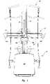
- FIG. 3shows a rear view of exercise apparatus 1 illustrating resistance assembly 20 in greater detail according to one aspect of the present invention.
- resistance assembly 20includes a resilient elongate rod 22 , a guide 24 , pulleys 26 a, b and pulleys 28 a, b .
- Resilient elongate rod 22is configured to provide resistance for use in exercise.
- Resilient elongate rod 22is positioned proximal to upright component support member 18 such that no portion of resilient elongate rod 22 is fixed in relation to support frame 10 or upright support member 18 . This allows resilient elongate rod 22 to move relative to other portions of exercise apparatus 1 in a flexible and desired manner.
- Guide 24is positioned relative to resilient elongate rod so as to ensure that movement of resilient elongate rod occurs in a predictable and orderly fashion.
- Guide 24includes a riser coupler 240 that spaces guide 24 apart from upright support member 18 . The desired displacement can substantially correspond with the width of resilient elongate rod 22 between guide member 24 and upright component support member 18 .
- Pulleys 26 a, bDisposed at the ends of resilient elongate rod 22 are pulleys 26 a, b .
- Pulleys 26 a, bare positioned below and toward the middle portion of resilient elongate rod 22 , although pulley 26 a, b can be disposed in alignment with or above the end of resilient elongate rod 22 .
- Pulleys 26 a, bcooperate with pulleys 28 a, b , which are affixed to upright component support member 18 , or more generally, are fixed relative to rod 22 , by way of a cable 29 .
- the cable 29provides a mechanism for conveying resistance from resilient elongate rod 22 to variable resistance system 30 .
- variable resistance system 30movement of variable resistance system 30 is transferred to movement of rods 22 by way of cable 29 , pulleys 26 a, b and 28 a, b .
- resistance assembly 20can be coupled to other components of exercise machine 1 utilizing a variety of mechanisms and in a variety of manners without departing from the scope and spirit of the present invention.
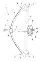
- FIG. 4Ais a perspective view of resistance assembly 20 illustrating resilient elongate rod 22 in a relaxed position.
- a bracket member 226is disposed at a center portion 220 of rod 22 .
- center portion 220is positioned at substantially the same elevation as first end 222 and second end 224 .
- Bracket member 226is positioned at or near center portion 220 of resilient elongate rod 22 .
- Bracket member 226is configured to slidably engage guide 24 .
- bracket membersAs will be appreciated by those skilled in the art, a variety of types and configurations of bracket members, guides, and other mechanisms for ensuring consistent and predictable movement of resilient elongate rod 22 can be utilized without departing from the scope and spirit of the present invention.
- guide 24 and bracket member 226allow for free movement of resilient elongate rod 22 .
- FIG. 4Billustrates resilient elongate rod 22 in a flexed configuration.
- a forceis exerted on cable 29 at a point below pulleys 28 a, b utilizing variable resistance system 30 .
- that forceis conveyed on the upper portion of pulleys 28 a, b .
- Thiscauses shortening of the portion of cable 29 above pulleys 28 a, b .
- Shortening of the cable 29causes pulleys 26 a, b to be pulled toward each other.
- center portion 220 of resilient elongate rod 22moves toward riser coupler 240 and rod 22 begins to flex.
- first end 222 , second end 224 , and center portion 220all move relative to one another and to other components of exercise machine 1 during exercise.
- the single resilient elongate rodis comprised of a plurality of resilient elongate rods that work together cooperatively.
- a plurality of resilient elongate rodsare utilized.
- two separate cablesare coupled to each end of the single resilient elongate rod.
- pulley length adjustment mechanisms 260 a and 260 bare provided. Due to the configuration of variable resistant system 30 , the amount of force required to flex resilient elongate rod 22 without utilizing the variable resistant system 30 can far exceed the capabilities of a normal user. As a result, a user may not be able to properly thread cable 29 around pulleys 26 a, b and pulleys 28 a, b during assembly or adjustment of exercise apparatus 1 under normal circumstances. Pulley length adjustment mechanisms 260 a, b disposed at ends 222 and 224 of rod 22 permit lateral displacement of pulleys 26 a, b allowing a user to loosen and/or tighten cable 29 . Pulley length adjustment mechanisms 260 a, b include adjustment member 262 a, b.
- adjustment mechanisms 260 a, bare slidably disposed at the ends 222 and 224 of rod 22 .
- Adjustment members 262 a, bcomprise threaded members that engage the ends 222 and 224 of rod 22 .
- pulley length adjustment mechanisms 260 a, bcooperatively interact with adjustment members 262 a, b to move closer to center portion 220 .
- tension on cable 29is lessened allowing a user to adjust and/or remove cable 29 from pulleys 26 a, b and pulleys 28 a, b.
- pulley length adjustment mechanisms 260 a, bmove toward first end 222 and second end 224 .
- tension on cable 29increases.
- resilient elongate rod 22is properly positioned for use during exercise.
- Pulley housing 280maintains the position of pulleys 28 a, b relative to one another. By maintaining the position of pulleys 28 a, b relative to one another, uniform and predictable movement of resilient or elongate rod 22 is maintained.
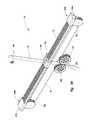
- FIG. 5illustrates a variable resistance system 30 according to one aspect of the present invention.
- Variable resistance system 30is configured to utilize resistance from one or more resilient elongate rods to provide a variable amount of resistance for use in exercise.
- Variable resistance system 30is coupled to upright component support member 18 at a transverse orientation.
- variable resistance system 30includes an automatic resistance adjustment mechanism 300 , a cable and pulley system 340 , a housing 380 , and a repetition sensor 390 .
- Housing 380is coupled to upright component support member 18 ( FIG. 2 ). Housing 380 provides a support structure on which other components of variable resistance system 30 can be mounted. Housing 380 includes a first frame member 382 , a second frame member 384 , a frame base 386 , and a casing 388 (see FIG. 3 ). First frame member 382 and second frame member 384 provide structural support and protection to other components of variable resistance system 30 . First and second frame members 382 and 384 provide sufficient strength to withstand resistance exerted on automatic resistance adjustment mechanism 300 and pulley system 340 .
- Frame base 386is coupled to the bottom of first and second frame members 382 and 384 .
- Frame base 386is also adapted to be coupled to upright component support member 18 and support base 16 .
- a casing 388is adapted to be positioned over first frame member 382 , second frame member 384 , frame base member 386 , and other components of variable resistance system 30 .
- Casing 388provides a decorative covering while also protecting the internal components of variable resistance system 30 from damage. Additionally, casing 388 prevents a user from interfering with operation of cable and pulley system 340 .
- Automatic resistance adjustment mechanism 300is pivotally mounted to housing 380 .
- automatic resistance adjustment mechanism 300is disposed between first frame member 382 and second frame member 384 .
- Automatic resistance adjustment mechanism 300cooperatively interacts with electronic weight selector control 40 to allow a user to select an amount of resistance to be utilized during exercise.
- Automatic resistance adjustment mechanism 300automatically changes the amount of resistance provided by variable resistance system 30 without requiring the user to manually adjust components of exercise apparatus 1 .
- automatic resistance adjustment mechanism 300includes a lever arm 302 , a lever arm length regulator 304 , and a lead screw motor assembly 310 .
- Lever arm 302cooperatively interacts with cable and pulley system 340 to regulate the amount of resistance required to displace resistance assembly cable 29 and by extension resilient elongate rod 22 .
- Lever arm length regulator 304is linked to resistance assembly cable 29 to cause displacement of resilient elongate rod 22 .
- linkedmeans directly coupled or indirectly coupled.
- Lever arm length regulator 304changes the effective length of lever arm 302 to provide a greater or lesser amount of mechanical advantage. By changing the amount of mechanical advantage provided by lever arm 302 , a greater or lesser amount of resistance is required to flex resilient elongate rod 22 .
- Lever arm length regulator 304is moved laterally by means of lead screw motor 314 .
- Lead screw motor assembly 310is coupled to lever arm 302 and lever arm length regular 304 .
- lead screw motor assemblyautomatically changes the position of lever arm length regulator to provide the desired amount of leverage benefit and thereby the desired amount of resistance for use during exercise.
- Lever arm length regulator 304engages a curved surface 326 of lever arm 302 .
- Curved surface 326is configured to maintain a constant tension on resistance assembly cable 29 notwithstanding the lateral position of lever arm length regulator 304 along lever arm 302 .
- a pivot 328provides a pivot point for lever arm 302 . Additionally, pivot 328 provides a point of coupling between lever arm 302 and housing 380 .
- lever arm 302positions the pulleys coupled to lever arm 302 at a desired displacement relative to other pulleys of the cable and pulley system 340 . This allows lever arm 302 to provide a desired effective lever arm length and predetermined mechanical advantage.
- the operation of lever arm 302 and other components of lead screw motor assembly 310will be described in greater detail with reference to FIGS. 7A , 7 B, 7 C, and 7 D.
- Cable and pulley system 340is coupled to several components of variable resistance system 30 including lever arm 302 and housing 380 .
- Cable and pulley system 340provides a compound pulley system to minimize the amount of force required to flex resilient elongate rod 22 .
- cable and pulley system 340includes a cable 342 , pulleys 344 , 346 , 348 , 350 , 352 , 354 , 356 , 358 , 360 , 362 , 364 , 366 , 368 , 370 and rotatable couplers 372 a,b.
- the first and second ends of cable 342are utilized by a user during exercise routines.
- the ends of cable 342can be coupled to exercise apparatus hand grips, or other mechanisms allowing a user to exert a force on the cable 342 .
- the followingis a discussion of an illustrative routing of cable 342 through pulleys 344 , 346 , 348 , 350 , 352 , 354 , 356 , 358 , 360 , 362 , 364 , 366 , 368 , 370 and is not intended to restrict the scope and spirit of the present invention.
- Cable 342is routed through pulleys 344 , 346 , 348 , 350 , 352 , 354 , 356 , 358 , 360 , 362 , 364 , 366 , 368 , 370 to ensure smooth and efficient movement of cable 324 , as well as to provide a compounding effect on the amount of resistance exerted by the user.
- a first end of cable 342extends from pulley 344 . Cable 342 is then routed from pulley 344 through pulley 346 and around pulley 348 . From pulley 348 , cable is routed through pulley 350 , around pulley 352 , to pulley 354 .
- the configuration of cable 342 and its juxtaposition with pulleys 344 , 346 , 348 , 350 , 352 , 354 , 356 , 358 , 360 , 362 , 364 , 366 , 368 , 370compounds the force exherted by the user on the cable and pulley system while also ensuring smooth and efficient operation of the movement of the cable.
- routing cable 342 through pulleys 344 , 346 , 348 , 350 , 352 , 354 , 356 , 358 , 360 , 362 , 364 , 366 , 368 , 370can be utilized without departing from the scope and spirit of the present invention.
- variable resistance system 30operates in connection with electronic weight selector control to move lever arm length regulator 304 to change the effective length of lever arm 302 thus changing the amount of resistance experienced by the user when moving the ends of cable 342 .
- exercise apparatus 1provides an efficient and user friendly mechanism for exercising.
- a set/rep sensor 390is shown.
- Set/rep sensor 390automatically detects the number of sets and repetitions that are performed by a user during an exercise being performed.
- set/rep sensorcomprises a magnetic sensor.
- Set/rep sensorincludes a first wheel 392 a and a second wheel 392 b .
- First and second wheels 392 a, binclude a metal disk with a plurality of voids formed therein. The voids allow a sensor mechanism (not shown) to detect both the movement and the direction of rotation of the metal disk.
- each direction changecorresponds with one half of a repetition.
- a set of an exercise routineincludes a plurality of repetitions.
- the senorincludes a light sensor.
- the sensordetects movement of the lever arm.
- FIG. 6is a top perspective view of lever arm 302 illustrating lead screw motor assembly 310 in greater detail.
- lead screw motor assembly 310includes a lead screw 312 , lead screw motor 314 , and a lead screw sensor 316 .
- Lead screw 312is threadably coupled to lever arm length regulator 304 .
- Lead screw 312is rotated utilizing lead screw motor 314 .
- lever arm length regulatoris cooperatively engaged by the threads of the lead screw 312 and moves in the direction of pivot 328 .
- lever arm length regulator 304is cooperatively engaged by the threads of lead screw 312 and moves in the direction of lead screw motor 314 .
- Lead screw motor 314is coupled to lever arm 302 .
- Lead screw motor 314provides the rotational force necessary to cause rotation of lead screw 312 and thereby lateral movement of lever arm length regulator 304 .
- lead screw motor 314includes a DC motor with an attached gear box.
- DC motorwith an attached gear box.
- a lead screw sensor 316is coupled to lead screw motor 314 .
- Lead screw sensor 316monitors the rotation of lead screw 312 and/or lead screw motor 314 to ascertain the position of lever arm length regulator 304 .
- lead screw sensor 316enables exercise apparatus 1 to automatically regulate the amount of the resistance provided by variable resistance system 30 and resistance assembly 20 .
- lever arm 302includes a first member 320 , a second member 322 , and a coupler 324 .
- First and second members 320 and 322both include a curved surface and an angled portion.
- First and second member 320 and 322are connected at one end by coupler 324 .
- the curved surface portions of first member and second member 320 and 322engage lever arm length regulator 304 .
- Lead screw 312is positioned between first member 320 and second member 322 .
- the lever armincludes a single lever member adapted to accommodate a lead screw and lever arm regulator.
- the actual length of the lever armis adapted to be adjusted instead of utilizing a lever arm length regulator.
- lever arm length regulator 304is coupled to a pulley 306 .
- Pulley 306accommodates resistance assembly cable 29 .
- the portion of resistance assembly cable 29 positioned in pulley 306is displaced with lever arm 302 .
- FIG. 7Aillustrates a variable resistance system 30 with lever arm length regulator 304 in an intermediate position.
- lever arm 302is in a relaxed position causing little or no displacement of cable 29 .
- the current position of lever arm 302is achieved when insufficient resistance is exerted on a cable and pulley system 340 to cause movement of the end of lever arm 302 corresponding with angle portion 330 .
- FIG. 7Bshows a lever arm 302 in a displaced configuration.
- the illustrated configuration of lever arm 302is achieved when sufficient force is exerted on the pulleys coupled to angle portion 330 of lever arm 302 .
- the displacement of the end of lever arm 202 corresponding with angle portion 330results in movement of lever arm length regulator 304 and resistance assembly cable 29 . Movement of resistance assembly cable 29 results in flexing of resilient elongate rod 22 .
- the configuration of lever arm 302results in movement of lever arm about pivot 328 .
- FIG. 7Cillustrates lever arm length regulator 304 at a lateral position adjacent pivot 328 .
- lever arm length regulator 304is at or near its greatest lateral displacement adjacent pivot 328 .
- the illustrated position of lever arm length regulator 304also corresponds with the smallest amount of resistance being experienced by the user. According to one embodiment of the present invention, a weight of less than 10 pounds is provided when lever arm length regulator 304 is in the illustrated position.
- the actual resistance experienced by the useris the result of a variety of factors including the length of the lever arm and the configuration of the cable and pulley system 340 .
- the mechanical advantage provided by lever arm 302is at its greatest.
- displacement of cable 342produces a large amount of movement of the end of lever arm 302 corresponding with angle portion 330 . While a large amount of movement of lever arm 302 is experienced, displacement of lever arm length regulator 304 and resistance assembly cable 29 is minimal.
- the compounding effect provided by the configuration of cable and pulley system 340results in a large amount of displacement of cable 342 of the cable and pulley system but a smaller amount of displacement of the end of lever arm 302 corresponding with angle portion 330 .
- This compound pulley effectallows the user to obtain a large amount of extension of the ends of cable 342 for a small amount of flexing of resilient elongate rod 22 .
- the combination of the compounding effect of cable and pulley system 340 and mechanical advantage of lever arm 302results in large amount of overall mechanical advantage. Thus, a small amount of effort is required to flex resilient elongate rod 22 .
- a resilient resistance membere.g. a biasing spring
- the resilient resistance memberprovides another source of resistance to variable resistance system 30 .
- the small amount of resistance provided by the resilient resistance memberallows a desired amount of minimum resistance to be provided where the effective length of lever arm 302 would provide insufficient resistance.
- the resilient resistance memberprovides a counter acting force to lower to the total resistance provided by the variable resistance system 30 and resistance assembly 20 .
- resilient resistance membercomprises a resilient band.
- FIG. 7Dillustrates a variable resistance system 30 with a lever arm length regulator 304 positioned adjacent the portion of lever arm 302 corresponding with angle portion 330 .
- the illustrated position of lever arm length regulator 304results in a minimal mechanical advantage being provided by lever arm 302 based on the small effective length of lever arm 302 .
- displacement of the end of lever arm 302 corresponding with angle portion 330is effectively the same displacement of lever arm length regulator 304 .
- displacement of the end of lever arm 302 corresponding with angle portion 330results in a large amount of displacement of resistance assembly cable 29 .
- the large amount of displacement of cable 29 and the small amount of mechanical advantage provided by lever arm 302results in a large amount of resistance being required to flex the resilient elongate member.
- the amount of resistance experienced when lever arm length regulator 304 is in the illustrated positionis approximately 440 pounds of resistance. In an alternative embodiment, the amount of the resistance experienced is approximately 340 pounds.
- a variety of types and configurations of variable resistance systems 30can result in a variety of types and amounts of resistance experienced by the user without departing from the scope and spirit of the present invention.
- FIG. 8shows an electronic weight selector control 40 according to one aspect of the present invention.
- Electronic weight selector control 40is coupled to upright component support member 18 .
- Electronic weight selector control 40allows a user to select an amount of resistance to be utilized in exercise.
- electronic weight selector controlincludes a control panel 400 .
- Control panel 400includes exercise indicia 410 , personal trainer selectors 420 , set/rep selectors 450 , and weight selector 460 .
- Exercise indicia 410provides a list of recommended exercise routines that can be utilized by the user in connection with exercise apparatus 1 .
- exercise indicia 410are arranged to allow a use to identify exercise routines adapted to benefit certain muscle groups.
- upper body exercisesinclude an incline press, a pectoral fly, a chest press, a bicep curl, a decline press, a shoulder press, an arm raise, and a tricep extension.
- Abs and back programsinclude a lat pull down, abdominal crunch, obliques, reverse fly, row, and back extension.
- Lower body exercisesinclude a squat, leg extension, hip adduction, glute kick, leg curl, and calf raise.
- the exercise indiciacan include color coded panels to facilitate coordination of exercise routines for certain muscle groups.
- Personal trainer selectors 420allow a user to select preprogrammed exercise routines adapted to provide physiological benefits corresponding with traditional types of personal training programs.
- personal trainer selectors 420include a next exercise button 422 , a personal trainer exercise display 424 , and selector buttons 426 through 446 .
- Next exercise button 422allows a user to begin a new exercise routine or skip an exercise routine altogether.
- Personal trainer exercise display 424indicates the exercise routine to be undertaken as a part of the personal training program.
- a chest press exercise routineis indicated as the exercise routine to be undertaken by the user.
- Selector buttons 426 - 446allow a user to select a preprogrammed exercise routine to be undertaken. Selector button 426 allows a user to select an upper body strength training routine. Selector button 428 allows a user to select an upper body circuit training routine. Selector button 429 allows a user to select an upper body weight loss routine. Selector button 437 allows a user to select an abs and back strength training routine. Selector button 434 allows a user to select an abs and back circuit training routine. Selector buttons 436 allows a user to select an abs and back weight loss routine. Selector button 442 allows a user to select a lower body strength training routine. Selector button 444 corresponds with the lower body circuit training routine. Selector button 446 allows a user to select a lower body weight loss routine.
- the userselects the preprogrammed exercise routine by depressing or otherwise actuating the appropriate selector button.
- the preprogrammed exercise routineautomatically indicates the exercise routine to be undertaken, the number of sets and reps to be conducted, and the amount of resistance in to be utilized.
- the usermay change the number of sets, reps and/or the resistance to be utilized in the routine.
- the exercise apparatus 1automatically detects the number of sets and reps conducted and changes the remaining number of sets and reps to be performed. Once the exercise routine is completed, the next exercise routine to be undertaken is displayed on the personal trainer exercise display 424 .
- Sets/reps selectors 450allow a user to select and/or change the number of sets and reps to be undertaken.
- Set/reps selectors 450include sets selector button 452 , sets numeric display 454 , reps selector button 456 , and reps numeric display 458 .
- Sets selector buttonallows the user to increase or decrease the number of sets to be undertaken in a given exercise routine.
- Sets numeric display 454indicates the number of sets to be undertaken by the user.
- Reps selector button 456allows the user to increase or decrease the number of reps to be undertaken in each set of an exercise routine.
- Reps numeric displayindicates the number of reps to be undertaken before completion of a given set of the exercise routine.
- Weight selector 460allows the user to identify and select a given amount of resistance to be utilized in an exercise routine.
- Weight selector button 460includes a weight selector button 462 , and a weight display 464 .
- Weight selector button 462allows the user to increase or decrease the amount of weight to be utilized in a given exercise routine.
- Weight display 464allows a user to identify the amount of resistance/weight set by the machine and to be utilized in the exercise routine.
- Weight selector display 460allows a user to quickly and efficiently select and/or change the amount of resistance to be utilized in the exercise.
- the increments and speed with which the resistance is changedcan vary based on the speed with which the user depresses the weight selector button 462 .
- the amount of resistancequickly changes.
- the weight changeoccurs more gradually and in smaller increments. This allows a user to quickly and accurately select a highly specific weight increment.
- the weightcan be changed in approximately one pound increments as the user approximates the desired weight to be utilized.
- FIG. 9is a perspective view of exercise apparatus 1 illustrating a squat apparatus 50 .
- Squat apparatus 50is slideably coupled to upright component support member 18 .
- a userconducts a squat routine by raising and lowering squat apparatus 50 .
- Squat apparatus 50includes cushioning member 52 and hand grip assemblies 54 a, b .
- Cushioning membercontacts a user's back during exercise while providing support and cushioning to forces exerted by the user against squat apparatus 50 .
- Hand grip assemblies 54 a, bare grasped by the user during exercise to raise and lower squat apparatus 50 .
- back support 64is disconnected from seat member 62 and removed from horizontal support member 14 . This allows the user to straddle horizontal support member 14 with the user's feet being positioned on support base 16 . The user then raises and lowers squat apparatus 50 by grasping hand grip assemblies 54 a, b while the user's back contacts cushioning member 52 .
- a variety of types and configurations of squat apparatusescan be utilized to conduct a squat routine without departing from the scope and spirit of the present invention.
- the configuration and angle of squat apparatus 50 on upright component support member 18ensures smooth and predictable movement during a squat routine. Additionally, the angle is adapted to minimize impact on the user's joints.
- FIG. 10illustrates an upright component support member 18 and squat apparatus 50 in greater detail.
- upright component support member 18includes a roller track 180 .
- Another roller track 180is positioned on the opposite side of upright component support member 18 .
- Squat apparatus 50includes a support frame 56 and rollers 58 a - d .
- Support frame 56provides a foundation on which cushioning member 52 , hand grip assemblies 54 a, b , and rollers 58 a - d are affixed.
- Rollers 58 a - dare positioned within roller track 180 .
- the configuration of rollers 58 a - d and roller track 180allows smooth and consistent sliding movement of squat apparatus 50 relative to upright component support member 18 .
- roller track 180is formed from an extruded aluminum material integrally coupled to upright component support member 18 .
- roller track 180may be utilized without departing from the scope and spirit of the present invention.
- Bicep/quad exerciser 70utilized in connection with the resilient elongate rod 22 .
- Bicep/quad exerciserincludes a quad portion 74 , a bicep portion 72 , and pivot 76 .
- Quad portion 76allows a user to conduct exercise routines relating to the quadriceps and other leg muscles.
- Biceps portion 72allows the user to conduct exercise routines related to the biceps and other muscles of the user's body.
- Pivot 76provides a point of rotation for allowing movement of bicep/quadricep exerciser 70 during exercise routines.
- bicep portion 72includes a support arm 720 a hand grip bar 722 , a coupler 724 , and cushion members 728 a, b .
- Hand grip bar 722includes the main support structure of bicep portion 72 .
- Hand grip bar 722provides a foundation on which other components of bicep portion 72 are positioned.
- Hand grip bar 722is adapted to be linked to support arm 720 .
- Hand grip baris adapted to be grasped by the user during bicep curls exercise routines and/or other exercise routines to be undertaken by the user.
- Coupler 724couples to support arm 720 to hand grip bar 722 .
- coupler 724includes a rigid member positioned at a transverse angle to support arm 720 .
- Coupler 724includes a hook 726 which is coupled to hand grip bar 722 to secure hand grip bar 722 to support arm 720 .
- Cushion members 728 a, bare coupled near one end of support arm 720 .
- Cushion members 728 a, bare adapted to provide protection and/or a mechanism for allowing a user to exercise utilizing bicep portion 72 .
- hand grip bar 722is integrally coupled to support arm 720 .
- a separate hand grip bar 722is selectably coupled directly to support arm 720 .
- Quad portion 74allows a user to exercise leg and/or other muscles. Quad portion 74 allows a user to exercise the user's quadricep muscles. Quad portion 74 is coupled directly to bicep portion 72 . Quad portion 74 includes a support member 740 , a hook 742 , and cushions 746 a, b . In the illustrated embodiment, support member 740 includes the main support structure for quad portion 74 . Support member 740 is the structure to which other components of quad portion 74 are coupled.
- Hook 742is coupled to the end of support member 740 .
- Hook 742is adapted to be coupled to a cable which is then coupled to one or both of the ends of cable 342 of cable and pulley system 340 .
- hook 742enables a user to utilize resistance from resilient elongate rod 22 to conduct exercises utilizing bicep/quad exercisers.
- Cushions 746 a, bare coupled at or near the end of support member 740 .
- Cushions 746 a, bare adapted to engage a user's foot, shin and/or other portion of the body to allow the user to conduct exercises such as quadriceps exercise routines.
Landscapes
- Health & Medical Sciences (AREA)
- Orthopedic Medicine & Surgery (AREA)
- General Health & Medical Sciences (AREA)
- Physical Education & Sports Medicine (AREA)
- Life Sciences & Earth Sciences (AREA)
- Biophysics (AREA)
- Rehabilitation Tools (AREA)
Abstract
Description
Claims (58)
Priority Applications (6)
| Application Number | Priority Date | Filing Date | Title |
|---|---|---|---|
| US10/647,729US7537552B2 (en) | 2003-08-25 | 2003-08-25 | Exercise device with centrally mounted resistance rod and automatic weight selector apparatus |
| CNB2004800244532ACN100522292C (en) | 2003-08-25 | 2004-02-18 | Exercise device |
| PCT/US2004/004470WO2005025682A1 (en) | 2003-08-25 | 2004-02-18 | Exercise device with centrally mounted resistance rod and automatic weight selector apparatus |
| EP04712270AEP1658117A4 (en) | 2003-08-25 | 2004-02-18 | Exercise device with centrally mounted resistance rod and automatic weight selector apparatus |
| US10/968,250US7429236B2 (en) | 2003-08-25 | 2004-10-19 | Exercise device with single resilient elongate rod and weight selector controller |
| US11/095,819US20050272577A1 (en) | 2003-01-10 | 2005-03-30 | Exercise apparatus with differential arm resistance assembly |
Applications Claiming Priority (1)
| Application Number | Priority Date | Filing Date | Title |
|---|---|---|---|
| US10/647,729US7537552B2 (en) | 2003-08-25 | 2003-08-25 | Exercise device with centrally mounted resistance rod and automatic weight selector apparatus |
Related Child Applications (1)
| Application Number | Title | Priority Date | Filing Date |
|---|---|---|---|
| US10/968,250Continuation-In-PartUS7429236B2 (en) | 2003-01-10 | 2004-10-19 | Exercise device with single resilient elongate rod and weight selector controller |
Publications (2)
| Publication Number | Publication Date |
|---|---|
| US20050049121A1 US20050049121A1 (en) | 2005-03-03 |
| US7537552B2true US7537552B2 (en) | 2009-05-26 |
Family
ID=34216582
Family Applications (1)
| Application Number | Title | Priority Date | Filing Date |
|---|---|---|---|
| US10/647,729Expired - Fee RelatedUS7537552B2 (en) | 2003-01-10 | 2003-08-25 | Exercise device with centrally mounted resistance rod and automatic weight selector apparatus |
Country Status (4)
| Country | Link |
|---|---|
| US (1) | US7537552B2 (en) |
| EP (1) | EP1658117A4 (en) |
| CN (1) | CN100522292C (en) |
| WO (1) | WO2005025682A1 (en) |
Cited By (71)
| Publication number | Priority date | Publication date | Assignee | Title |
|---|---|---|---|---|
| US20070054790A1 (en)* | 2003-02-20 | 2007-03-08 | Alliance Design & Development Group, Inc. | Exercise apparatus resistance unit |
| US7798946B2 (en) | 2002-06-14 | 2010-09-21 | Icon Ip, Inc. | Exercise device with centrally mounted resistance rod |
| US20100323852A1 (en)* | 2009-06-19 | 2010-12-23 | Locsin Dwight D | Yoke training system |
| US20130225377A1 (en)* | 2012-02-23 | 2013-08-29 | Superweigh Enterprise Co., Ltd. | Stretching Exercise Apparatus |
| US8690735B2 (en) | 1999-07-08 | 2014-04-08 | Icon Health & Fitness, Inc. | Systems for interaction with exercise device |
| US8758201B2 (en) | 1999-07-08 | 2014-06-24 | Icon Health & Fitness, Inc. | Portable physical activity sensing system |
| US9028368B2 (en) | 1999-07-08 | 2015-05-12 | Icon Health & Fitness, Inc. | Systems, methods, and devices for simulating real world terrain on an exercise device |
| US20160114205A1 (en)* | 2013-05-28 | 2016-04-28 | Marco Giunchi | Gymnastic machine |
| WO2016064603A1 (en)* | 2014-10-21 | 2016-04-28 | Total Gym Global Corp. | Exercise device and method of using same |
| CN105664423A (en)* | 2014-11-16 | 2016-06-15 | 青岛瑞箭机电工程技术有限公司 | Leg-hung barbell weight apparatus |
| US9833654B1 (en) | 2012-11-23 | 2017-12-05 | Clifford Ernest Gant | Hand-held adjustable exercise apparatus |
| US9895570B2 (en)* | 2010-10-08 | 2018-02-20 | Recovery Science, Llp | Exercise device |
| WO2018132354A1 (en) | 2017-01-11 | 2018-07-19 | Jeffrey Owen Meredith | Exercise weight selection device and method |
| US10188890B2 (en) | 2013-12-26 | 2019-01-29 | Icon Health & Fitness, Inc. | Magnetic resistance mechanism in a cable machine |
| US10212994B2 (en) | 2015-11-02 | 2019-02-26 | Icon Health & Fitness, Inc. | Smart watch band |
| US10220259B2 (en) | 2012-01-05 | 2019-03-05 | Icon Health & Fitness, Inc. | System and method for controlling an exercise device |
| US10226396B2 (en) | 2014-06-20 | 2019-03-12 | Icon Health & Fitness, Inc. | Post workout massage device |
| US10252109B2 (en) | 2016-05-13 | 2019-04-09 | Icon Health & Fitness, Inc. | Weight platform treadmill |
| US10272317B2 (en) | 2016-03-18 | 2019-04-30 | Icon Health & Fitness, Inc. | Lighted pace feature in a treadmill |
| US10279212B2 (en) | 2013-03-14 | 2019-05-07 | Icon Health & Fitness, Inc. | Strength training apparatus with flywheel and related methods |
| US10293211B2 (en) | 2016-03-18 | 2019-05-21 | Icon Health & Fitness, Inc. | Coordinated weight selection |
| US10391361B2 (en) | 2015-02-27 | 2019-08-27 | Icon Health & Fitness, Inc. | Simulating real-world terrain on an exercise device |
| US10426989B2 (en) | 2014-06-09 | 2019-10-01 | Icon Health & Fitness, Inc. | Cable system incorporated into a treadmill |
| US10433612B2 (en) | 2014-03-10 | 2019-10-08 | Icon Health & Fitness, Inc. | Pressure sensor to quantify work |
| US10441840B2 (en) | 2016-03-18 | 2019-10-15 | Icon Health & Fitness, Inc. | Collapsible strength exercise machine |
| US10449416B2 (en) | 2015-08-26 | 2019-10-22 | Icon Health & Fitness, Inc. | Strength exercise mechanisms |
| US10493349B2 (en) | 2016-03-18 | 2019-12-03 | Icon Health & Fitness, Inc. | Display on exercise device |
| US10500473B2 (en) | 2016-10-10 | 2019-12-10 | Icon Health & Fitness, Inc. | Console positioning |
| US10525300B1 (en)* | 2012-06-11 | 2020-01-07 | Donald Jeffrey Boatwright | Multipurpose exercise stand for compound fitness training |
| US10561894B2 (en) | 2016-03-18 | 2020-02-18 | Icon Health & Fitness, Inc. | Treadmill with removable supports |
| US10625137B2 (en) | 2016-03-18 | 2020-04-21 | Icon Health & Fitness, Inc. | Coordinated displays in an exercise device |
| US10661114B2 (en) | 2016-11-01 | 2020-05-26 | Icon Health & Fitness, Inc. | Body weight lift mechanism on treadmill |
| US10671705B2 (en) | 2016-09-28 | 2020-06-02 | Icon Health & Fitness, Inc. | Customizing recipe recommendations |
| US10729965B2 (en) | 2017-12-22 | 2020-08-04 | Icon Health & Fitness, Inc. | Audible belt guide in a treadmill |
| US10786706B2 (en) | 2018-07-13 | 2020-09-29 | Icon Health & Fitness, Inc. | Cycling shoe power sensors |
| US10918905B2 (en) | 2016-10-12 | 2021-02-16 | Icon Health & Fitness, Inc. | Systems and methods for reducing runaway resistance on an exercise device |
| US10940360B2 (en) | 2015-08-26 | 2021-03-09 | Icon Health & Fitness, Inc. | Strength exercise mechanisms |
| US10953305B2 (en) | 2015-08-26 | 2021-03-23 | Icon Health & Fitness, Inc. | Strength exercise mechanisms |
| US11000730B2 (en) | 2018-03-16 | 2021-05-11 | Icon Health & Fitness, Inc. | Elliptical exercise machine |
| US11033777B1 (en) | 2019-02-12 | 2021-06-15 | Icon Health & Fitness, Inc. | Stationary exercise machine |
| US11058913B2 (en) | 2017-12-22 | 2021-07-13 | Icon Health & Fitness, Inc. | Inclinable exercise machine |
| US11058914B2 (en) | 2016-07-01 | 2021-07-13 | Icon Health & Fitness, Inc. | Cooling methods for exercise equipment |
| US11187285B2 (en) | 2017-12-09 | 2021-11-30 | Icon Health & Fitness, Inc. | Systems and methods for selectively rotationally fixing a pedaled drivetrain |
| US11244751B2 (en) | 2012-10-19 | 2022-02-08 | Finish Time Holdings, Llc | Method and device for providing a person with training data of an athlete as the athlete is performing a swimming workout |
| US11298577B2 (en) | 2019-02-11 | 2022-04-12 | Ifit Inc. | Cable and power rack exercise machine |
| US11326673B2 (en) | 2018-06-11 | 2022-05-10 | Ifit Inc. | Increased durability linear actuator |
| US11451108B2 (en) | 2017-08-16 | 2022-09-20 | Ifit Inc. | Systems and methods for axial impact resistance in electric motors |
| US11446534B2 (en)* | 2019-03-26 | 2022-09-20 | Phillip Knox | Portable collapsible full body strength fitness system |
| US11534651B2 (en) | 2019-08-15 | 2022-12-27 | Ifit Inc. | Adjustable dumbbell system |
| US11534654B2 (en) | 2019-01-25 | 2022-12-27 | Ifit Inc. | Systems and methods for an interactive pedaled exercise device |
| US20230124790A1 (en)* | 2021-10-15 | 2023-04-20 | Yangzhou Jiuyi Hardware & Machinery Co., Ltd. | Fitness exercise apparatus |
| US20230131649A1 (en)* | 2021-10-27 | 2023-04-27 | Hong-Jun Yeh | Explosive strength training device |
| US11673036B2 (en) | 2019-11-12 | 2023-06-13 | Ifit Inc. | Exercise storage system |
| US11794070B2 (en) | 2019-05-23 | 2023-10-24 | Ifit Inc. | Systems and methods for cooling an exercise device |
| US11850497B2 (en) | 2019-10-11 | 2023-12-26 | Ifit Inc. | Modular exercise device |
| US11878199B2 (en) | 2021-02-16 | 2024-01-23 | Ifit Inc. | Safety mechanism for an adjustable dumbbell |
| US11925829B1 (en) | 2020-08-20 | 2024-03-12 | Hablamer, Llc | Adjustable exercise bench |
| US20240082631A1 (en)* | 2022-09-12 | 2024-03-14 | Michael Stephenson | Multi-function exercise apparatus with integrated treadmill, exercise platform, pull up and chin up station, push sled and resistance pulleys |
| US11931621B2 (en) | 2020-03-18 | 2024-03-19 | Ifit Inc. | Systems and methods for treadmill drift avoidance |
| US11951377B2 (en) | 2020-03-24 | 2024-04-09 | Ifit Inc. | Leaderboard with irregularity flags in an exercise machine system |
| US20240195195A1 (en)* | 2022-12-08 | 2024-06-13 | Dynamic Accession LLC | Self contained, regenerative, dynamic motion resistance module |
| US12029935B2 (en) | 2021-08-19 | 2024-07-09 | Ifit Inc. | Adjustment mechanism for an adjustable kettlebell |
| US12029961B2 (en) | 2020-03-24 | 2024-07-09 | Ifit Inc. | Flagging irregularities in user performance in an exercise machine system |
| US12176009B2 (en) | 2021-12-30 | 2024-12-24 | Ifit Inc. | Systems and methods for synchronizing workout equipment with video files |
| US12219201B2 (en) | 2021-08-05 | 2025-02-04 | Ifit Inc. | Synchronizing video workout programs across multiple devices |
| US12263371B2 (en) | 2021-04-27 | 2025-04-01 | Ifit Inc. | Devices, systems, and methods for rotating a tread belt in two directions |
| US12280294B2 (en) | 2021-10-15 | 2025-04-22 | Ifit Inc. | Magnetic clutch for a pedaled drivetrain |
| US12350573B2 (en) | 2021-04-27 | 2025-07-08 | Ifit Inc. | Systems and methods for cross-training on exercise devices |
| US12350547B2 (en) | 2022-02-28 | 2025-07-08 | Ifit Inc. | Devices, systems, and methods for moving a movable step through a transition zone |
| US12409375B2 (en) | 2022-03-18 | 2025-09-09 | Ifit Inc. | Systems and methods for haptic simulation in incline exercise devices |
| US12433815B2 (en) | 2020-10-02 | 2025-10-07 | Ifit Inc. | Massage roller with pressure sensors |
Families Citing this family (59)
| Publication number | Priority date | Publication date | Assignee | Title |
|---|---|---|---|---|
| US7083554B1 (en) | 1997-02-27 | 2006-08-01 | Nautilus, Inc. | Exercise machine with infinite position range limiter and automatic belt tensioning system |
| US7628737B2 (en)* | 2004-08-11 | 2009-12-08 | Icon Ip, Inc. | Repetition sensor in exercise equipment |
| US7108641B2 (en) | 2000-05-03 | 2006-09-19 | Nautilus, Inc. | Exercise equipment with multi-positioning handles |
| US7429236B2 (en) | 2003-08-25 | 2008-09-30 | Icon Ip, Inc. | Exercise device with single resilient elongate rod and weight selector controller |
| US20050272577A1 (en)* | 2003-01-10 | 2005-12-08 | Olson Michael L | Exercise apparatus with differential arm resistance assembly |
| US20050037904A1 (en)* | 2003-08-12 | 2005-02-17 | Shih-Chang Chang | Body exercising device |
| US7037246B2 (en)* | 2003-09-12 | 2006-05-02 | Kellion Corporation | Spring pack |
| US7594881B2 (en)* | 2004-05-26 | 2009-09-29 | Tessema Dosho Shifferaw | Compact weight bench |
| US20060035772A1 (en)* | 2004-08-16 | 2006-02-16 | Nautilus, Inc. | Attachment and mounting assembly for an exercise bench |
| US7815552B2 (en)* | 2004-10-12 | 2010-10-19 | Nautilus, Inc. | Exercise device |
| US7892155B2 (en)* | 2005-01-14 | 2011-02-22 | Nautilus, Inc. | Exercise device |
| USD533910S1 (en) | 2005-03-15 | 2006-12-19 | Nautilus, Inc. | Exercise device |
| US20070093369A1 (en)* | 2005-10-21 | 2007-04-26 | Bocchicchio Vincent J | Resistance exercise method and system |
| US7862489B2 (en)* | 2006-07-17 | 2011-01-04 | Studio Moderna Sa | Multipurpose exercise system |
| US20080096735A1 (en)* | 2006-07-24 | 2008-04-24 | Tuffstuff Fitness Equipment Inc. | Mechanism for adjustable arms and seat pad apparatus and method |
| US20090149302A1 (en)* | 2007-12-10 | 2009-06-11 | Michael Thuma | Folding multi-purpose exercise apparatus with exchangeable engines |
| EP2155340B1 (en)* | 2007-12-21 | 2011-07-20 | Cybex International, Inc. | Exercise apparatus and method with selectively variable stabilization |
| CN102133466B (en)* | 2010-11-17 | 2013-03-27 | 青岛英派斯健康科技有限公司 | Method for automatically controlling resistance of spontaneous electrical damping treadmill by utilizing body weight |
| US10016646B2 (en)* | 2012-09-14 | 2018-07-10 | BodyForce, Inc. | Multifunctional exercise machines |
| US9724553B2 (en) | 2013-03-15 | 2017-08-08 | Arqex Outdoor Fitness Systems, Llc | Resistance band assembly and a method of varying a resistive force applied thereby |
| USD753246S1 (en) | 2013-03-15 | 2016-04-05 | Arqex Outdoor Fitness Systems, Llc | Strength training and stretching machine |
| US9555278B2 (en) | 2013-03-15 | 2017-01-31 | Arqfx Outdoor Fitness Systems, Llc | Strength training and stretching system and resistance band assembly for use therewith |
| USD745939S1 (en) | 2013-03-15 | 2015-12-22 | Arqex Outdoor Fitness Systems, Llc | Strength training and stretching machine with adjustable arms |
| US9682267B2 (en) | 2013-03-15 | 2017-06-20 | Arqex Outdoor Fitness Systems, Llc | Insert for use with a resistance band assembly and a method of using the same |
| US9314658B2 (en)* | 2013-03-15 | 2016-04-19 | Arqex Outdoor Fitness Systems, Llc | Strength training and stretching system |
| US9555280B2 (en) | 2013-03-15 | 2017-01-31 | Arqex Outdoor Fitness Systems, Llc | Attachment assembly for an exercise device and an exercise device incorporating the same |
| US9630048B2 (en) | 2013-03-15 | 2017-04-25 | Arqex Outdoor Fitness Systems, Llc | Variable resistance band assembly and method of using the same |
| US10398920B2 (en) | 2014-02-26 | 2019-09-03 | Jeffrey Owen Meredith | Exercise weight selection device and method |
| WO2015130988A1 (en)* | 2014-02-26 | 2015-09-03 | Meredith Jeffrey Owen | Exercise weight selection device and method |
| US10709922B2 (en) | 2014-02-26 | 2020-07-14 | Hoist Fitness Systems, Inc. | Exercise weight selection device and method |
| WO2015138546A1 (en)* | 2014-03-11 | 2015-09-17 | Cybex International, Inc. | Arm extension exercise apparatus |
| CN105080037A (en)* | 2014-04-28 | 2015-11-25 | 青岛瑞箭机电工程技术有限公司 | Arm muscle recovery exerciser |
| US10258828B2 (en) | 2015-01-16 | 2019-04-16 | Icon Health & Fitness, Inc. | Controls for an exercise device |
| USD777850S1 (en) | 2015-01-16 | 2017-01-31 | Arqex Outdoor Fitness Systems, Llc | Variable resistance band |
| CN104815421A (en)* | 2015-04-06 | 2015-08-05 | 李久德 | Electric control exercising machine |
| CN105080045A (en)* | 2015-07-27 | 2015-11-25 | 杨元义 | Combined type physical exercise running machine |
| KR101636657B1 (en)* | 2015-10-15 | 2016-07-05 | 백준영 | Electric apparatus for assistanting training |
| CN105749495A (en)* | 2016-04-05 | 2016-07-13 | 安徽机电职业技术学院 | Smart safe weightlifting bed special for body building and body shaping |
| US10471299B2 (en) | 2016-07-01 | 2019-11-12 | Icon Health & Fitness, Inc. | Systems and methods for cooling internal exercise equipment components |
| US10441844B2 (en) | 2016-07-01 | 2019-10-15 | Icon Health & Fitness, Inc. | Cooling systems and methods for exercise equipment |
| US10376736B2 (en) | 2016-10-12 | 2019-08-13 | Icon Health & Fitness, Inc. | Cooling an exercise device during a dive motor runway condition |
| TWI646997B (en) | 2016-11-01 | 2019-01-11 | 美商愛康運動與健康公司 | Distance sensor for console positioning |
| TWI680782B (en) | 2016-12-05 | 2020-01-01 | 美商愛康運動與健康公司 | Offsetting treadmill deck weight during operation |
| US11040231B2 (en)* | 2017-01-30 | 2021-06-22 | Arena Innovation Corp. | Systems for dynamic resistance training |
| CN108926811A (en)* | 2017-05-23 | 2018-12-04 | 石磊 | Fitness equipment |
| CN111317966B (en)* | 2018-05-23 | 2021-02-12 | 褚健翔 | Fitness bench press frame with protection function and method |
| CN111097140A (en)* | 2019-12-31 | 2020-05-05 | 深圳依讯诺科技有限公司 | A elasticity adjustment mechanism and body-building gravity frame for body-building gravity frame |
| USD933760S1 (en)* | 2020-09-24 | 2021-10-19 | Rocdan Limited | Fitness equipment |
| USD975217S1 (en)* | 2020-11-25 | 2023-01-10 | Ningbo Tiande Xinyi Trading Co., Ltd. | Dumb bell stool |
| CN112807192B (en)* | 2021-01-15 | 2022-07-05 | 广西科技大学 | A horizontal rehabilitation training device |
| JP7158071B1 (en)* | 2021-08-31 | 2022-10-21 | 東庚企業股▲ふん▼有限公司 | training device resistance device |
| CN114082143A (en)* | 2021-10-26 | 2022-02-25 | 浙江警察学院 | Multi-functional sports physical training equipment |
| CN114082137B (en)* | 2021-12-10 | 2023-03-17 | 阳光经销商公司 | Comprehensive training device |
| CN114949728A (en)* | 2022-05-24 | 2022-08-30 | 张凯 | Single-motor-driven differential transmission mechanism of intelligent strength training instrument |
| CA3209816A1 (en)* | 2022-06-15 | 2023-12-15 | Hyun Jung Byun | Bent over row machine |
| KR102511110B1 (en)* | 2022-06-15 | 2023-03-16 | (주)뉴텍웰니스 | Bent over row machine |
| USD1022085S1 (en) | 2023-05-22 | 2024-04-09 | Dane Hoover | Exercise bench |
| WO2025068944A1 (en)* | 2023-09-27 | 2025-04-03 | Australian Fitness Supplies Pty Ltd. | Exercise bench capable of utilizing a resistance device of an exercise apparatus |
| US12420139B2 (en)* | 2023-10-26 | 2025-09-23 | Kerry Reeves | Exercise apparatus for strengthening leg muscles |
Citations (147)
| Publication number | Priority date | Publication date | Assignee | Title |
|---|---|---|---|---|
| US9695A (en) | 1853-05-03 | Richard l | ||
| US192338A (en) | 1877-06-26 | Improvement in exercising-machines | ||
| US325435A (en) | 1885-09-01 | north | ||
| US428912A (en) | 1890-05-27 | Archery-bow | ||
| US484352A (en) | 1892-10-11 | Charles william aytoxst | ||
| US588350A (en) | 1896-12-04 | 1897-08-17 | Frank p | |
| US610716A (en) | 1898-09-13 | District | ||
| US685788A (en) | 1900-12-21 | 1901-11-05 | Bernard Adolphus Mcfadden | Exercising apparatus. |
| US754992A (en) | 1903-03-26 | 1904-03-22 | Charles A Grabner | Exercising apparatus. |
| US807670A (en) | 1904-09-10 | 1905-12-19 | Charles A Grabner | Exercising apparatus. |
| US852193A (en) | 1906-04-04 | 1907-04-30 | Archie B Mcmillan | Electric exercising apparatus. |
| US964745A (en) | 1909-05-19 | 1910-07-19 | Robert Blakoe | Device for developing and strengthening the muscles of the body and arms. |
| US1019861A (en) | 1910-06-24 | 1912-03-12 | Henry W Titus | Exercising apparatus. |
| US1115826A (en) | 1913-11-07 | 1914-11-03 | Frank G Johnson | Strength-testing device. |
| US1123272A (en) | 1913-02-12 | 1915-01-05 | William R Goodman | Exercising device. |
| US1144085A (en) | 1913-10-21 | 1915-06-22 | Arthur Abplanalp | Exercising apparatus for use in a lying position. |
| US1495278A (en) | 1921-06-06 | 1924-05-27 | Henry W Titus | Grip exerciser |
| US1539214A (en) | 1923-07-19 | 1925-05-26 | Willis G Shockey | Exercising device |
| US1576474A (en) | 1924-07-03 | 1926-03-09 | Sheridan A Walker | Exerciser |
| US1585748A (en) | 1925-04-28 | 1926-05-25 | Albert C Wendelken | Exercising apparatus |
| US1698831A (en) | 1926-11-11 | 1929-01-15 | Titus Weimar Harry | Universal exercising device |
| GB325435A (en) | 1929-05-10 | 1930-02-20 | John Malcolm Thomson | Improvements in and relating to exercising apparatus |
| GB374240A (en) | 1931-05-20 | 1932-06-09 | Charles William Preston | Improvements in exercising apparatus |
| GB466901A (en) | 1936-01-03 | 1937-06-08 | Leslie Whittington Landon | Improvements in or relating to exercising apparatus |
| GB496740A (en) | 1936-02-25 | 1938-12-02 | Antoine Garcia | Improvements in physical culture apparatus |
| US2346105A (en) | 1943-02-27 | 1944-04-04 | Textile Machine Works | Control device for ringless yarn carrier attachments |
| US2456017A (en) | 1947-09-08 | 1948-12-14 | Marion A Park | Polio exercising machine |
| US2641250A (en) | 1950-12-27 | 1953-06-09 | Healthomatic Corp | Attachment for exercising machines |
| US2763156A (en) | 1955-06-14 | 1956-09-18 | Sebastian J Garigal | Bow pull indicating machine |
| US2843858A (en) | 1954-03-29 | 1958-07-22 | Bjorklund Berma | Lift strap and exerciser for recumbent persons |
| US2855200A (en) | 1955-12-01 | 1958-10-07 | Blickman Harry | Home exercising apparatus |
| GB841537A (en) | 1956-12-20 | 1960-07-20 | Edward Bolton Ltd | A hand exercising appliance |
| US2968337A (en) | 1959-02-11 | 1961-01-17 | George H Bartlett | Child's adjustable exerciser |
| US3000628A (en) | 1958-04-21 | 1961-09-19 | Loren P Kellogg | Bow stringer |
| US3342485A (en) | 1965-03-18 | 1967-09-19 | Gaul Martin | Exercising bench comprising hinged and adjustable seating portions |
| US3370584A (en) | 1964-11-25 | 1968-02-27 | Girten William | Apparatus for the stimulation of blood circulation in the feet and legs |
| US3465592A (en) | 1965-09-14 | 1969-09-09 | James J Perrine | Isokinetic exercise process and apparatus |
| US3567219A (en) | 1969-05-16 | 1971-03-02 | Timothy G Foster | Universal physical exercising device |
| US3601398A (en) | 1969-04-14 | 1971-08-24 | Louis R Brochman | Ball-hitting practice device |
| US3638941A (en) | 1968-09-10 | 1972-02-01 | Franz Kulkens | Physical exercise apparatus with user-actuated arm which is movable against a variable bias |
| US3640528A (en) | 1969-08-22 | 1972-02-08 | Richard Proctor | Pull-type variable weight exercising device |
| US3658327A (en) | 1971-03-10 | 1972-04-25 | Clifford S Thiede | Pull type exercising device |
| US3664916A (en) | 1969-09-25 | 1972-05-23 | Rhodiaceta | Polyamide-based composite filaments |
| US3690655A (en) | 1968-06-21 | 1972-09-12 | Richard L Chapman | A manually operable cantilevered type exercising device |
| US3708167A (en) | 1970-12-17 | 1973-01-02 | J Potgieter | Exercising apparatus |
| GB1326704A (en) | 1971-02-03 | 1973-08-15 | Czeczerski N | Exercising equipment |
| US3797624A (en) | 1972-01-13 | 1974-03-19 | Mandrel Industries | Conveyer guide |
| US3858874A (en) | 1973-02-22 | 1975-01-07 | Internax Holdings Ltd | Push-pull type of exercising device |
| DE2346105A1 (en) | 1973-09-13 | 1975-03-27 | Ertl Josef | Hand gripped movement exercise apparatus - consisting of two sprung sticks connected by a flexible rod and distance pieces |
| US3884464A (en) | 1973-09-12 | 1975-05-20 | George D Evangelos | Exerciser |
| US3891207A (en) | 1974-01-11 | 1975-06-24 | Merle M Helliwell | Exerciser device |
| US3892404A (en) | 1974-10-30 | 1975-07-01 | Theodore Martucci | Exercise device |
| US3918710A (en) | 1973-03-29 | 1975-11-11 | Frank J Niebojewski | Rowing lever exercise apparatus |
| US3957266A (en) | 1975-04-18 | 1976-05-18 | Max Rice | Exercising post and platform |
| US3958803A (en) | 1974-07-03 | 1976-05-25 | Werner Geisselbrecht | Gymnastic push-pull exercise appliance |
| US3981500A (en) | 1974-10-17 | 1976-09-21 | Ryan Vernon L | Adjustable support apparatus |
| US4026548A (en) | 1975-07-02 | 1977-05-31 | Daniel Lee Birdwell | Spring type exercise device |
| US4063727A (en) | 1976-07-19 | 1977-12-20 | Hall James A | Arm wrestling exercise device |
| US4072309A (en) | 1976-06-21 | 1978-02-07 | Wilson Jerry Lee | Multi-purpose exercise device |
| US4074409A (en)* | 1976-05-04 | 1978-02-21 | Smith Jimmie T | Compound bow string changer |
| US4076237A (en) | 1977-03-21 | 1978-02-28 | Dussia Melvin A | Spring type back traction exerciser |
| US4082267A (en) | 1976-05-12 | 1978-04-04 | Flavell Evan R | Bilateral isokinetic exerciser |
| US4131701A (en) | 1977-05-27 | 1978-12-26 | Exxon Research & Engineering Co. | Composite tubular elements |
| US4157181A (en) | 1976-05-07 | 1979-06-05 | Fansteel Inc. | Graphite fiber tapered shafts |
| US4207879A (en) | 1976-08-04 | 1980-06-17 | Gary J. Safadago | Therapeutic apparatus for use in treatment of muscular and skeletal disorders |
| JPS55148571U (en) | 1979-04-13 | 1980-10-25 | ||
| US4231568A (en) | 1979-01-29 | 1980-11-04 | Riley Robert Q | Exercise machine with spring-cam arrangement for equalizing the force required through the exercise stroke |
| DE2810632C3 (en) | 1978-03-11 | 1981-01-08 | Josef 4790 Paderborn Peitz Sen. | Trimmer |
| US4263897A (en) | 1979-05-04 | 1981-04-28 | Olympus Optical Co., Ltd. | Endoscope |
| US4307880A (en) | 1977-11-15 | 1981-12-29 | Abram Gin Y | Device for yoga exercising |
| US4316610A (en) | 1976-12-30 | 1982-02-23 | Hinds Robert S | Segmented elastic cable exerciser bar |
| US4316609A (en) | 1979-02-15 | 1982-02-23 | Diversified Products Corporation | Bench mounted weight lifting exerciser |
| US4328965A (en) | 1980-06-16 | 1982-05-11 | Hatfield Raymond C | Portable archery muscle developer |
| US4334678A (en) | 1978-04-28 | 1982-06-15 | Doyel John S | Exerciser |
| US4355061A (en) | 1981-08-13 | 1982-10-19 | Shakespeare Company | Composite tubular rod and method for making same |
| US4354675A (en) | 1979-06-12 | 1982-10-19 | Global Gym & Fitness Equipment Limited | Weight lifting device |
| US4384715A (en) | 1980-12-17 | 1983-05-24 | John P. Barrett, Jr. | Knee exerciser |
| US4426077A (en) | 1980-03-25 | 1984-01-17 | Becker Hermann Josef | Muscle developing exercise device |
| US4428577A (en) | 1979-07-25 | 1984-01-31 | Michael Croom | Exerciser |
| DE3231228A1 (en) | 1982-08-21 | 1984-02-23 | Volker 3252 Bad Münder Hundertmark | Device for building up human muscles |
| US4441708A (en) | 1978-06-12 | 1984-04-10 | Brentham Jerry D | Double leg curl exercising device |
| US4465276A (en) | 1981-04-30 | 1984-08-14 | Black & Decker Inc. | Exercise apparatus with relatively rotatable arms |
| US4494662A (en) | 1983-03-04 | 1985-01-22 | Clymer Ronald S | Mounted spring device for resisting flexing |
| US4521013A (en) | 1982-04-08 | 1985-06-04 | Supafit Gymnasium Equipment Pty. Ltd. | Resilient type exercising device |
| US4569519A (en) | 1984-04-12 | 1986-02-11 | Portable Isokinetics, Inc. | Shoulder exercising apparatus |
| US4603855A (en) | 1981-01-02 | 1986-08-05 | Sebelle Leslie W | Variable exercise apparatus |
| US4603856A (en) | 1984-10-02 | 1986-08-05 | Fiore Russell D | Exercising device |
| US4608969A (en) | 1983-03-04 | 1986-09-02 | Hamlin Jerry F | Portable traction apparatus |
| US4620701A (en) | 1984-08-20 | 1986-11-04 | Mojden Daniel R | Adjustable exercise apparatus |
| US4620704A (en)* | 1984-04-27 | 1986-11-04 | Tessema Shifferaw | Universal exercising machine |
| US4647040A (en) | 1982-03-26 | 1987-03-03 | Treco Products Inc. | Leg stretching apparatus |
| US4685670A (en) | 1984-10-01 | 1987-08-11 | Harold Zinkin | Elastic tension exercising apparatus with multiple pass cable and pulley |
| US4721303A (en) | 1985-01-31 | 1988-01-26 | Fitzpatrick Patrick C | Convertible multi-function physical exerciser |
| US4725057A (en) | 1984-04-27 | 1988-02-16 | Tessema Shifferaw | Universal exercising machine |
| US4741530A (en) | 1985-10-31 | 1988-05-03 | Wolf Hans Gerd | Power training arrangement |
| US4743010A (en) | 1986-08-11 | 1988-05-10 | Alexander Geraci | Dynamic powered rowing machine |
| US4750738A (en) | 1987-02-26 | 1988-06-14 | Dang Chi H | Physical exercise apparatus for isokinetic and eccentric training |
| US4756527A (en) | 1987-04-14 | 1988-07-12 | Ledbetter Daniel R | Gripping assembly for use with cable exercising equipment |
| US4772015A (en) | 1987-04-23 | 1988-09-20 | The Toro Company | Shoulder and arm exercise machine |
| US4790596A (en) | 1987-06-26 | 1988-12-13 | Shifferaw Tessema D | Resilient chair |
| US4826158A (en) | 1988-02-01 | 1989-05-02 | Fields Jr Thomas H | Body stretching and exercising device |
| US4844453A (en) | 1988-03-21 | 1989-07-04 | Century Martial Art Supply, Inc. | Stretching machine |
| US4877239A (en) | 1989-01-03 | 1989-10-31 | Gregorio Dela Rosa | Thigh muscle stretching device |
| US4898381A (en) | 1988-11-23 | 1990-02-06 | Gordon Joel D | Multi-exercise system |
| US4907795A (en) | 1986-04-04 | 1990-03-13 | Fike Corporation | Computerized exercise monitoring system and method for monitoring a user's exercise performance |
| US5005832A (en) | 1989-08-18 | 1991-04-09 | Hoeven Martin A V D | Portable abdominal exerciser |
| US5022377A (en)* | 1990-01-08 | 1991-06-11 | Stevens Richard L | Portable bow press |
| US5039088A (en) | 1990-04-26 | 1991-08-13 | Shifferaw Tessema D | Exercise machine |
| US5108090A (en) | 1991-06-10 | 1992-04-28 | Reed Michael S | Back exercising apparatus |
| US5123886A (en)* | 1990-01-24 | 1992-06-23 | Cook Brian R | Exercise machine with adjustable grip positioning mechanism |
| US5141483A (en) | 1991-01-14 | 1992-08-25 | Smith David C | Exercise apparatus for lumbar and truncal regions |
| US5151071A (en)* | 1990-10-05 | 1992-09-29 | Baltimore Therapeutic Equipment Co. | Isoinertial lifting device |
| US5176601A (en) | 1991-11-27 | 1993-01-05 | Reynolds Kelly P | Exercising apparatus |
| US5195937A (en) | 1990-03-28 | 1993-03-23 | Nordictrack, Inc. | Multi-exercise apparatus |
| US5209223A (en) | 1991-03-20 | 1993-05-11 | Biodex Medical Systems, Inc. | Single chair muscle exercise and rehabilitation apparatus |
| US5211617A (en)* | 1991-10-31 | 1993-05-18 | Millen Roy F | Torsion exercising device |
| US5254066A (en)* | 1991-03-13 | 1993-10-19 | Motivator, Inc. | User force application device for an exercise, physical therapy, or rehabilitation apparatus |
| US5316534A (en) | 1992-02-14 | 1994-05-31 | Proform Fitness Products, Inc. | Multipurpose exercise machine |
| US5318495A (en) | 1992-12-14 | 1994-06-07 | Harry Malynowsky | Method for improving circulation by oscillation of a resilient foot rest |
| US5320591A (en) | 1991-05-10 | 1994-06-14 | Harmon Larry S | Versatile exercise apparatus |
| US5330405A (en) | 1993-10-25 | 1994-07-19 | Pacific Fitness Corporation | Exercise machine |
| US5421801A (en) | 1993-06-08 | 1995-06-06 | Davies, Iii; D. Robert | Stretching machine |
| US5472399A (en) | 1995-04-24 | 1995-12-05 | Szekely; Andre | Apparatus for exercising the penis |
| US5480212A (en) | 1993-11-18 | 1996-01-02 | Reliance Medical Products, Inc. | Medical instrument positioner and patient support apparatus |
| US5529560A (en) | 1993-06-08 | 1996-06-25 | David Dise | Stretch therapy apparatus for physical fitness, rehabilitation and medical treatment |
| US5895342A (en)* | 1997-01-13 | 1999-04-20 | Solland; Kurt M. | Portable exercise device |
| US5967950A (en) | 1998-02-26 | 1999-10-19 | Hsu; Hank | Load mechanism of body building device |
| US6003294A (en) | 1998-05-04 | 1999-12-21 | Ag - Right Enterprises | Crop harvesting rod array |
| US6011134A (en) | 1998-01-30 | 2000-01-04 | E. I. Du Pont De Nemours And Company | Method for manufacturing poly(hexamethylene adipamide) from monomethyladipate and hexamethylenediamine |
| US6027429A (en) | 1993-11-03 | 2000-02-22 | Nordictrack, Inc. | Variable resistance exercise device |
| US6082346A (en)* | 1998-11-18 | 2000-07-04 | High Country Archery, Inc. | Compound bow cams and modules |
| US6113522A (en)* | 1993-05-26 | 2000-09-05 | Robert N. Montgomery | Exercise apparatus |
| US6172178B1 (en) | 1997-03-13 | 2001-01-09 | Dsm N.V. | Car parts made from a polyamide composition |
| US6217495B1 (en) | 1994-01-03 | 2001-04-17 | Theodore Yalch | Symmetrical exercise apparatus |
| US6238323B1 (en) | 1999-09-14 | 2001-05-29 | The Simonson Family Limited Partnership Rlllp | Cable crossover exercise apparatus |
| US6238322B1 (en) | 1999-08-18 | 2001-05-29 | Hank Hsu | Exercise machine having a sliding seat selectively coupled to a sliding damping member |
| WO2001085262A1 (en) | 2000-04-24 | 2001-11-15 | Oh Kyoung Chan | Elasticity-controllable trampoline using plate spring |
| US6319179B1 (en) | 1998-12-28 | 2001-11-20 | Robert Sylvester Hinds | Single spine elastic cord exercise assembly |
| US6335100B1 (en) | 1985-05-31 | 2002-01-01 | Sumitomo Rubber Industries, Ltd. | Structural material and process for its production |
| US6342028B1 (en) | 1999-08-14 | 2002-01-29 | De Sane Joseph R | Magnetic counter for exercise equipment |
| US6585626B2 (en)* | 2000-12-18 | 2003-07-01 | Stamina Products, Inc. | Bench exerciser with upwardly diverging bungee cord supports |
| US6595905B2 (en) | 2000-12-18 | 2003-07-22 | Stamina Products, Inc. | Exerciser with multiple bungee cord resistance and enhanced bench movements |
| US6685607B1 (en) | 2003-01-10 | 2004-02-03 | Icon Ip, Inc. | Exercise device with resistance mechanism having a pivoting arm and a resistance member |
| US20050143230A1 (en) | 2003-08-25 | 2005-06-30 | Dalebout William T. | Exercise device with single resilient elongate rod and weight selector controller |
| US20060035768A1 (en) | 2004-08-11 | 2006-02-16 | Kowallis Rodney C | Repetition sensor in exercise equipment |
| US7197029B1 (en) | 2000-09-29 | 2007-03-27 | Nortel Networks Limited | System and method for network phone having adaptive transmission modes |
| US7250022B2 (en) | 2002-06-14 | 2007-07-31 | Dalebout William T | Exercise device with centrally mounted resistance rod |
Family Cites Families (4)
| Publication number | Priority date | Publication date | Assignee | Title |
|---|---|---|---|---|
| US356219A (en)* | 1887-01-18 | Revolving window-curtain exhibitor | ||
| US4328968A (en)* | 1978-09-28 | 1982-05-11 | Chuck Hacker | Protective pad for the thumb hole of a bowling ball |
| DE3541980A1 (en)* | 1985-11-28 | 1987-06-04 | Rk Sportgeraete Vertriebs Gmbh | Physical-training apparatus |
| US4743015A (en)* | 1986-07-28 | 1988-05-10 | The Fitness Agency | Exercise device simulating cross country skiing |
- 2003
- 2003-08-25USUS10/647,729patent/US7537552B2/ennot_activeExpired - Fee Related
- 2004
- 2004-02-18CNCNB2004800244532Apatent/CN100522292C/ennot_activeExpired - Fee Related
- 2004-02-18EPEP04712270Apatent/EP1658117A4/ennot_activeWithdrawn
- 2004-02-18WOPCT/US2004/004470patent/WO2005025682A1/enactiveApplication Filing
Patent Citations (151)
| Publication number | Priority date | Publication date | Assignee | Title |
|---|---|---|---|---|
| US9695A (en) | 1853-05-03 | Richard l | ||
| US192338A (en) | 1877-06-26 | Improvement in exercising-machines | ||
| US325435A (en) | 1885-09-01 | north | ||
| US428912A (en) | 1890-05-27 | Archery-bow | ||
| US484352A (en) | 1892-10-11 | Charles william aytoxst | ||
| US610716A (en) | 1898-09-13 | District | ||
| US588350A (en) | 1896-12-04 | 1897-08-17 | Frank p | |
| US685788A (en) | 1900-12-21 | 1901-11-05 | Bernard Adolphus Mcfadden | Exercising apparatus. |
| US754992A (en) | 1903-03-26 | 1904-03-22 | Charles A Grabner | Exercising apparatus. |
| US807670A (en) | 1904-09-10 | 1905-12-19 | Charles A Grabner | Exercising apparatus. |
| US852193A (en) | 1906-04-04 | 1907-04-30 | Archie B Mcmillan | Electric exercising apparatus. |
| US964745A (en) | 1909-05-19 | 1910-07-19 | Robert Blakoe | Device for developing and strengthening the muscles of the body and arms. |
| US1019861A (en) | 1910-06-24 | 1912-03-12 | Henry W Titus | Exercising apparatus. |
| US1123272A (en) | 1913-02-12 | 1915-01-05 | William R Goodman | Exercising device. |
| US1144085A (en) | 1913-10-21 | 1915-06-22 | Arthur Abplanalp | Exercising apparatus for use in a lying position. |
| US1115826A (en) | 1913-11-07 | 1914-11-03 | Frank G Johnson | Strength-testing device. |
| US1495278A (en) | 1921-06-06 | 1924-05-27 | Henry W Titus | Grip exerciser |
| US1539214A (en) | 1923-07-19 | 1925-05-26 | Willis G Shockey | Exercising device |
| US1576474A (en) | 1924-07-03 | 1926-03-09 | Sheridan A Walker | Exerciser |
| US1585748A (en) | 1925-04-28 | 1926-05-25 | Albert C Wendelken | Exercising apparatus |
| US1698831A (en) | 1926-11-11 | 1929-01-15 | Titus Weimar Harry | Universal exercising device |
| GB325435A (en) | 1929-05-10 | 1930-02-20 | John Malcolm Thomson | Improvements in and relating to exercising apparatus |
| GB374240A (en) | 1931-05-20 | 1932-06-09 | Charles William Preston | Improvements in exercising apparatus |
| GB466901A (en) | 1936-01-03 | 1937-06-08 | Leslie Whittington Landon | Improvements in or relating to exercising apparatus |
| GB496740A (en) | 1936-02-25 | 1938-12-02 | Antoine Garcia | Improvements in physical culture apparatus |
| US2346105A (en) | 1943-02-27 | 1944-04-04 | Textile Machine Works | Control device for ringless yarn carrier attachments |
| US2456017A (en) | 1947-09-08 | 1948-12-14 | Marion A Park | Polio exercising machine |
| US2641250A (en) | 1950-12-27 | 1953-06-09 | Healthomatic Corp | Attachment for exercising machines |
| US2843858A (en) | 1954-03-29 | 1958-07-22 | Bjorklund Berma | Lift strap and exerciser for recumbent persons |
| US2763156A (en) | 1955-06-14 | 1956-09-18 | Sebastian J Garigal | Bow pull indicating machine |
| US2855200A (en) | 1955-12-01 | 1958-10-07 | Blickman Harry | Home exercising apparatus |
| GB841537A (en) | 1956-12-20 | 1960-07-20 | Edward Bolton Ltd | A hand exercising appliance |
| US3000628A (en) | 1958-04-21 | 1961-09-19 | Loren P Kellogg | Bow stringer |
| US2968337A (en) | 1959-02-11 | 1961-01-17 | George H Bartlett | Child's adjustable exerciser |
| US3370584A (en) | 1964-11-25 | 1968-02-27 | Girten William | Apparatus for the stimulation of blood circulation in the feet and legs |
| US3342485A (en) | 1965-03-18 | 1967-09-19 | Gaul Martin | Exercising bench comprising hinged and adjustable seating portions |
| US3465592A (en) | 1965-09-14 | 1969-09-09 | James J Perrine | Isokinetic exercise process and apparatus |
| US3690655A (en) | 1968-06-21 | 1972-09-12 | Richard L Chapman | A manually operable cantilevered type exercising device |
| US3638941A (en) | 1968-09-10 | 1972-02-01 | Franz Kulkens | Physical exercise apparatus with user-actuated arm which is movable against a variable bias |
| US3601398A (en) | 1969-04-14 | 1971-08-24 | Louis R Brochman | Ball-hitting practice device |
| US3567219A (en) | 1969-05-16 | 1971-03-02 | Timothy G Foster | Universal physical exercising device |
| US3640528A (en) | 1969-08-22 | 1972-02-08 | Richard Proctor | Pull-type variable weight exercising device |
| US3664916A (en) | 1969-09-25 | 1972-05-23 | Rhodiaceta | Polyamide-based composite filaments |
| US3708167A (en) | 1970-12-17 | 1973-01-02 | J Potgieter | Exercising apparatus |
| GB1326704A (en) | 1971-02-03 | 1973-08-15 | Czeczerski N | Exercising equipment |
| US3658327A (en) | 1971-03-10 | 1972-04-25 | Clifford S Thiede | Pull type exercising device |
| US3797624A (en) | 1972-01-13 | 1974-03-19 | Mandrel Industries | Conveyer guide |
| US3858874A (en) | 1973-02-22 | 1975-01-07 | Internax Holdings Ltd | Push-pull type of exercising device |
| US3918710A (en) | 1973-03-29 | 1975-11-11 | Frank J Niebojewski | Rowing lever exercise apparatus |
| US3884464A (en) | 1973-09-12 | 1975-05-20 | George D Evangelos | Exerciser |
| DE2346105A1 (en) | 1973-09-13 | 1975-03-27 | Ertl Josef | Hand gripped movement exercise apparatus - consisting of two sprung sticks connected by a flexible rod and distance pieces |
| US3891207A (en) | 1974-01-11 | 1975-06-24 | Merle M Helliwell | Exerciser device |
| US3958803A (en) | 1974-07-03 | 1976-05-25 | Werner Geisselbrecht | Gymnastic push-pull exercise appliance |
| US3981500A (en) | 1974-10-17 | 1976-09-21 | Ryan Vernon L | Adjustable support apparatus |
| US3892404A (en) | 1974-10-30 | 1975-07-01 | Theodore Martucci | Exercise device |
| US3957266A (en) | 1975-04-18 | 1976-05-18 | Max Rice | Exercising post and platform |
| US4026548A (en) | 1975-07-02 | 1977-05-31 | Daniel Lee Birdwell | Spring type exercise device |
| US4074409A (en)* | 1976-05-04 | 1978-02-21 | Smith Jimmie T | Compound bow string changer |
| US4157181A (en) | 1976-05-07 | 1979-06-05 | Fansteel Inc. | Graphite fiber tapered shafts |
| US4082267B1 (en) | 1976-05-12 | 1993-04-27 | R Flavell Evan | |
| US4082267A (en) | 1976-05-12 | 1978-04-04 | Flavell Evan R | Bilateral isokinetic exerciser |
| US4072309A (en) | 1976-06-21 | 1978-02-07 | Wilson Jerry Lee | Multi-purpose exercise device |
| US4072309B1 (en) | 1976-06-21 | 1984-03-06 | ||
| US4063727A (en) | 1976-07-19 | 1977-12-20 | Hall James A | Arm wrestling exercise device |
| US4207879A (en) | 1976-08-04 | 1980-06-17 | Gary J. Safadago | Therapeutic apparatus for use in treatment of muscular and skeletal disorders |
| US4316610A (en) | 1976-12-30 | 1982-02-23 | Hinds Robert S | Segmented elastic cable exerciser bar |
| US4076237A (en) | 1977-03-21 | 1978-02-28 | Dussia Melvin A | Spring type back traction exerciser |
| US4131701A (en) | 1977-05-27 | 1978-12-26 | Exxon Research & Engineering Co. | Composite tubular elements |
| US4307880A (en) | 1977-11-15 | 1981-12-29 | Abram Gin Y | Device for yoga exercising |
| DE2810632C3 (en) | 1978-03-11 | 1981-01-08 | Josef 4790 Paderborn Peitz Sen. | Trimmer |
| US4334678A (en) | 1978-04-28 | 1982-06-15 | Doyel John S | Exerciser |
| US4441708A (en) | 1978-06-12 | 1984-04-10 | Brentham Jerry D | Double leg curl exercising device |
| US4231568A (en) | 1979-01-29 | 1980-11-04 | Riley Robert Q | Exercise machine with spring-cam arrangement for equalizing the force required through the exercise stroke |
| US4316609A (en) | 1979-02-15 | 1982-02-23 | Diversified Products Corporation | Bench mounted weight lifting exerciser |
| JPS55148571U (en) | 1979-04-13 | 1980-10-25 | ||
| US4263897A (en) | 1979-05-04 | 1981-04-28 | Olympus Optical Co., Ltd. | Endoscope |
| US4354675A (en) | 1979-06-12 | 1982-10-19 | Global Gym & Fitness Equipment Limited | Weight lifting device |
| US4428577A (en) | 1979-07-25 | 1984-01-31 | Michael Croom | Exerciser |
| US4426077A (en) | 1980-03-25 | 1984-01-17 | Becker Hermann Josef | Muscle developing exercise device |
| US4328965A (en) | 1980-06-16 | 1982-05-11 | Hatfield Raymond C | Portable archery muscle developer |
| US4384715A (en) | 1980-12-17 | 1983-05-24 | John P. Barrett, Jr. | Knee exerciser |
| US4603855A (en) | 1981-01-02 | 1986-08-05 | Sebelle Leslie W | Variable exercise apparatus |
| US4465276A (en) | 1981-04-30 | 1984-08-14 | Black & Decker Inc. | Exercise apparatus with relatively rotatable arms |
| US4355061A (en) | 1981-08-13 | 1982-10-19 | Shakespeare Company | Composite tubular rod and method for making same |
| US4647040A (en) | 1982-03-26 | 1987-03-03 | Treco Products Inc. | Leg stretching apparatus |
| US4521013A (en) | 1982-04-08 | 1985-06-04 | Supafit Gymnasium Equipment Pty. Ltd. | Resilient type exercising device |
| DE3231228A1 (en) | 1982-08-21 | 1984-02-23 | Volker 3252 Bad Münder Hundertmark | Device for building up human muscles |
| US4494662A (en) | 1983-03-04 | 1985-01-22 | Clymer Ronald S | Mounted spring device for resisting flexing |
| US4608969A (en) | 1983-03-04 | 1986-09-02 | Hamlin Jerry F | Portable traction apparatus |
| US4569519A (en) | 1984-04-12 | 1986-02-11 | Portable Isokinetics, Inc. | Shoulder exercising apparatus |
| US4620704A (en)* | 1984-04-27 | 1986-11-04 | Tessema Shifferaw | Universal exercising machine |
| US4725057A (en) | 1984-04-27 | 1988-02-16 | Tessema Shifferaw | Universal exercising machine |
| US4620701A (en) | 1984-08-20 | 1986-11-04 | Mojden Daniel R | Adjustable exercise apparatus |
| US4685670A (en) | 1984-10-01 | 1987-08-11 | Harold Zinkin | Elastic tension exercising apparatus with multiple pass cable and pulley |
| US4603856A (en) | 1984-10-02 | 1986-08-05 | Fiore Russell D | Exercising device |
| US4721303A (en) | 1985-01-31 | 1988-01-26 | Fitzpatrick Patrick C | Convertible multi-function physical exerciser |
| US6335100B1 (en) | 1985-05-31 | 2002-01-01 | Sumitomo Rubber Industries, Ltd. | Structural material and process for its production |
| US4741530A (en) | 1985-10-31 | 1988-05-03 | Wolf Hans Gerd | Power training arrangement |
| US4907795A (en) | 1986-04-04 | 1990-03-13 | Fike Corporation | Computerized exercise monitoring system and method for monitoring a user's exercise performance |
| US4743010A (en) | 1986-08-11 | 1988-05-10 | Alexander Geraci | Dynamic powered rowing machine |
| US4750738A (en) | 1987-02-26 | 1988-06-14 | Dang Chi H | Physical exercise apparatus for isokinetic and eccentric training |
| US4756527A (en) | 1987-04-14 | 1988-07-12 | Ledbetter Daniel R | Gripping assembly for use with cable exercising equipment |
| US4772015A (en) | 1987-04-23 | 1988-09-20 | The Toro Company | Shoulder and arm exercise machine |
| US4790596A (en) | 1987-06-26 | 1988-12-13 | Shifferaw Tessema D | Resilient chair |
| US4826158A (en) | 1988-02-01 | 1989-05-02 | Fields Jr Thomas H | Body stretching and exercising device |
| US4844453A (en) | 1988-03-21 | 1989-07-04 | Century Martial Art Supply, Inc. | Stretching machine |
| US4898381A (en) | 1988-11-23 | 1990-02-06 | Gordon Joel D | Multi-exercise system |
| US4877239A (en) | 1989-01-03 | 1989-10-31 | Gregorio Dela Rosa | Thigh muscle stretching device |
| US5005832A (en) | 1989-08-18 | 1991-04-09 | Hoeven Martin A V D | Portable abdominal exerciser |
| US5022377A (en)* | 1990-01-08 | 1991-06-11 | Stevens Richard L | Portable bow press |
| US5123886A (en)* | 1990-01-24 | 1992-06-23 | Cook Brian R | Exercise machine with adjustable grip positioning mechanism |
| US5195937A (en) | 1990-03-28 | 1993-03-23 | Nordictrack, Inc. | Multi-exercise apparatus |
| US5039088A (en) | 1990-04-26 | 1991-08-13 | Shifferaw Tessema D | Exercise machine |
| US5151071A (en)* | 1990-10-05 | 1992-09-29 | Baltimore Therapeutic Equipment Co. | Isoinertial lifting device |
| US5141483A (en) | 1991-01-14 | 1992-08-25 | Smith David C | Exercise apparatus for lumbar and truncal regions |
| US5254066A (en)* | 1991-03-13 | 1993-10-19 | Motivator, Inc. | User force application device for an exercise, physical therapy, or rehabilitation apparatus |
| US5209223A (en) | 1991-03-20 | 1993-05-11 | Biodex Medical Systems, Inc. | Single chair muscle exercise and rehabilitation apparatus |
| US5320591A (en) | 1991-05-10 | 1994-06-14 | Harmon Larry S | Versatile exercise apparatus |
| US5108090A (en) | 1991-06-10 | 1992-04-28 | Reed Michael S | Back exercising apparatus |
| US5211617A (en)* | 1991-10-31 | 1993-05-18 | Millen Roy F | Torsion exercising device |
| US5176601A (en) | 1991-11-27 | 1993-01-05 | Reynolds Kelly P | Exercising apparatus |
| US5316534A (en) | 1992-02-14 | 1994-05-31 | Proform Fitness Products, Inc. | Multipurpose exercise machine |
| US5318495A (en) | 1992-12-14 | 1994-06-07 | Harry Malynowsky | Method for improving circulation by oscillation of a resilient foot rest |
| US6113522A (en)* | 1993-05-26 | 2000-09-05 | Robert N. Montgomery | Exercise apparatus |
| US5529560A (en) | 1993-06-08 | 1996-06-25 | David Dise | Stretch therapy apparatus for physical fitness, rehabilitation and medical treatment |
| US5421801A (en) | 1993-06-08 | 1995-06-06 | Davies, Iii; D. Robert | Stretching machine |
| US5626547A (en) | 1993-06-08 | 1997-05-06 | David Dise | Stretch therapy apparatus for physical fitness, rehabilitation and medical treatment |
| US5330405B1 (en) | 1993-10-25 | 1998-11-03 | Pacific Fitness Corp | Exercise machine |
| US5330405A (en) | 1993-10-25 | 1994-07-19 | Pacific Fitness Corporation | Exercise machine |
| US6027429A (en) | 1993-11-03 | 2000-02-22 | Nordictrack, Inc. | Variable resistance exercise device |
| US5480212A (en) | 1993-11-18 | 1996-01-02 | Reliance Medical Products, Inc. | Medical instrument positioner and patient support apparatus |
| US6217495B1 (en) | 1994-01-03 | 2001-04-17 | Theodore Yalch | Symmetrical exercise apparatus |
| US5472399A (en) | 1995-04-24 | 1995-12-05 | Szekely; Andre | Apparatus for exercising the penis |
| US5895342A (en)* | 1997-01-13 | 1999-04-20 | Solland; Kurt M. | Portable exercise device |
| US6172178B1 (en) | 1997-03-13 | 2001-01-09 | Dsm N.V. | Car parts made from a polyamide composition |
| US6011134A (en) | 1998-01-30 | 2000-01-04 | E. I. Du Pont De Nemours And Company | Method for manufacturing poly(hexamethylene adipamide) from monomethyladipate and hexamethylenediamine |
| US5967950A (en) | 1998-02-26 | 1999-10-19 | Hsu; Hank | Load mechanism of body building device |
| US6003294A (en) | 1998-05-04 | 1999-12-21 | Ag - Right Enterprises | Crop harvesting rod array |
| US6082346A (en)* | 1998-11-18 | 2000-07-04 | High Country Archery, Inc. | Compound bow cams and modules |
| US6319179B1 (en) | 1998-12-28 | 2001-11-20 | Robert Sylvester Hinds | Single spine elastic cord exercise assembly |
| US6342028B1 (en) | 1999-08-14 | 2002-01-29 | De Sane Joseph R | Magnetic counter for exercise equipment |
| US6238322B1 (en) | 1999-08-18 | 2001-05-29 | Hank Hsu | Exercise machine having a sliding seat selectively coupled to a sliding damping member |
| US6238323B1 (en) | 1999-09-14 | 2001-05-29 | The Simonson Family Limited Partnership Rlllp | Cable crossover exercise apparatus |
| WO2001085262A1 (en) | 2000-04-24 | 2001-11-15 | Oh Kyoung Chan | Elasticity-controllable trampoline using plate spring |
| US7197029B1 (en) | 2000-09-29 | 2007-03-27 | Nortel Networks Limited | System and method for network phone having adaptive transmission modes |
| US6585626B2 (en)* | 2000-12-18 | 2003-07-01 | Stamina Products, Inc. | Bench exerciser with upwardly diverging bungee cord supports |
| US6595905B2 (en) | 2000-12-18 | 2003-07-22 | Stamina Products, Inc. | Exerciser with multiple bungee cord resistance and enhanced bench movements |
| US7250022B2 (en) | 2002-06-14 | 2007-07-31 | Dalebout William T | Exercise device with centrally mounted resistance rod |
| US6685607B1 (en) | 2003-01-10 | 2004-02-03 | Icon Ip, Inc. | Exercise device with resistance mechanism having a pivoting arm and a resistance member |
| US20050143230A1 (en) | 2003-08-25 | 2005-06-30 | Dalebout William T. | Exercise device with single resilient elongate rod and weight selector controller |
| US20060035768A1 (en) | 2004-08-11 | 2006-02-16 | Kowallis Rodney C | Repetition sensor in exercise equipment |
Non-Patent Citations (44)
| Title |
|---|
| 2002 Project Abstract (including "University of Wyoming Zero Gravity Construction"), printed Aug. 20, 2002, 9 pgs. |
| 3422 Hall-Effect, Direction-Detection Sensor, Copyright 2001, 2003, Allegro MicroSystems, Inc. available online at www.allegomicro.com, p. 1-10. |
| A3425 Ultra-Sensitive Dual-Channel Quadrature Hall-Effect Bipolar Switch, Copyright 2005, Allegro MicroSystems, Inc. available online at www.allegromicro.com, p. 1-21. |
| Advertisement for Breitbart Muscle Building Apparatus, Breitbart Pupils Say it with Muscles!, May 4, 1929 (3 pages). |
| Advertisement for Broom's Advanced International Course, Superman publication, Dec. 1938 (1 page). |
| Advertisement for Canadiana, Big 16, Body-Building publication, Feb. 1962 (1 page). |
| Advertisement for Marcy Gymnasium Equipment Co., Physical Power publication, Apr. 1964 (1 page). |
| Advertisement for Universal Twister in Athletik Sport Journal (Holland), 1972 (1 page). |
| Advertisement for Weider's Giant Multiplex Builder, Muscle Power publication, Jan. 1949 (1 page). |
| Battle for the Best Pecs, printed Aug. 20, 2002, 3 pgs. |
| Bowflex Trainer, Power Rod Resistance, printed Aug 20, 2002, 1 pg. |
| Bowflex(R) Power Pro(R), Assembly Manual, Copyright 2000, 28 pgs. |
| Bowflex(R) Power Pro(R), Owner's Manual & Fitness Guide, Copyright 2001, 80 pgs. |
| Bowflex.com, Get Results with a Blowlfex Home Gym, printed Sep. 17, 2002, Copyright 2002, 2 pgs. |
| Bowflex® Power Pro®, Assembly Manual, Copyright 2000, 28 pgs. |
| Bowflex® Power Pro®, Owner's Manual & Fitness Guide, Copyright 2001, 80 pgs. |
| Breitbart Muscle Builder Apparatus, Breitbard Pupils Say it with Muscles!, May 4, 1929 (3 pages). |
| Broom Hall, Broom's Advanced International Course (1 page). |
| Canadiana, Big 16 (1 page). |
| Inventor disclosure by Tessema Shifferaw relating to Ex-Stick I, available on information and belief at least as early as Sep. 1982 (5 pages). |
| Inventor disclosure by Tessema Shifferaw relating to Ex-Stick II, available on information and belief at an unknown date later than Sep. 1982 (1 page). |
| Lat Pulldown Attachment Assembly Instructions, available, on information and belief, at least as early as Mar. 2002, 10 pgs. |
| LeonardFitness.com, Bandflex Home Gym, printed Aug. 14, 2002, Copyright 1999-2001, 4 pgs. |
| LeonardFitness.com, Bowflex(R) Power Pro, printied Aug. 20, 2002, Copyright 1999-2001, 3 pgs. |
| LeonardFitness.com, Bowflex® Power Pro, printied Aug. 20, 2002, Copyright 1999-2001, 3 pgs. |
| Marcy Gymnasium Equipment Co., Physical Fitness Equipment for the Entire Family (1 page). |
| MegaFitness.com, Band Flex Home Gym, printed Aug. 14, 2002, Copyright 1997-2002, 5 pgs. |
| NickPicks.com, As Seen on TV Bowflex, printed Aug. 20, 2002, 3 pgs. |
| Notice of Allowance and Fee(s) Due dated Mar. 14, 2008, U.S. Appl. No. 10/968,250, 6 pages. |
| Notice of Allowance and Fee(s) Due, dated mailed Jul. 13, 2007, 7 pages, U.S. Appl. No. 10/968,250. |
| Notice of Allowance and Fee(s) Due, dated mailed Nov. 28, 2007, 7 pages, U.S. Appl. No. 10/968,250. |
| Office Action dated Mar. 23, 2007, 9 pages, U.S. Appl. No. 10/968,250. |
| Office Action dated Sep. 18, 2006, 11 pages, U.S. Appl. No. 10/968,250. |
| Owner's Manual for Impex Fitness Products, Powerhouse Home Gym WM 1400, Revised Jun. 30, 2000. |
| Response to Office Action dated Apr. 23, 2007, 25 pages, U.S. Appl. No. 10/968,250, with Terminal Disclaimer dated Apr. 23, 2007. |
| Response to Office Action dated Dec. 14, 2006, 25 pages, U.S. Appl. No. 10/968,250. |
| RetroSearch, nerac.com, printed Jul. 2, 2004 (4 pages). |
| Reviewboard.com, Bowflex Power Pro XTLU, printed Aug. 20, 2002, 2 pgs. |
| Soloflex.com, Soloflex(R), Compound Barbell, printed Sep. 17, 2002, 1 pg. |
| Soloflex.com, Soloflex®, Compound Barbell, printed Sep. 17, 2002, 1 pg. |
| Supplementary European Search Report dated May 9, 2008, from the European Patent Office, 6 pages. |
| Verlag Athletik, Universal Twister (1 page). |
| Website, www.bowflex.com, printed Sep. 17, 2002, 96 pgs. |
| Weider Barbell Co., Giant Multiplex Builder (1 page). |
Cited By (114)
| Publication number | Priority date | Publication date | Assignee | Title |
|---|---|---|---|---|
| US8758201B2 (en) | 1999-07-08 | 2014-06-24 | Icon Health & Fitness, Inc. | Portable physical activity sensing system |
| US9028368B2 (en) | 1999-07-08 | 2015-05-12 | Icon Health & Fitness, Inc. | Systems, methods, and devices for simulating real world terrain on an exercise device |
| US8690735B2 (en) | 1999-07-08 | 2014-04-08 | Icon Health & Fitness, Inc. | Systems for interaction with exercise device |
| US7798946B2 (en) | 2002-06-14 | 2010-09-21 | Icon Ip, Inc. | Exercise device with centrally mounted resistance rod |
| US7762935B2 (en)* | 2003-02-20 | 2010-07-27 | Doble William C | Exercise apparatus resistance unit |
| US20070054790A1 (en)* | 2003-02-20 | 2007-03-08 | Alliance Design & Development Group, Inc. | Exercise apparatus resistance unit |
| US20100323852A1 (en)* | 2009-06-19 | 2010-12-23 | Locsin Dwight D | Yoke training system |
| US11179593B2 (en) | 2010-10-08 | 2021-11-23 | Recovery Science Llc | Exercise device |
| US10441839B2 (en) | 2010-10-08 | 2019-10-15 | Recovery Science, Llc | Exercise device |
| US9895570B2 (en)* | 2010-10-08 | 2018-02-20 | Recovery Science, Llp | Exercise device |
| US10220259B2 (en) | 2012-01-05 | 2019-03-05 | Icon Health & Fitness, Inc. | System and method for controlling an exercise device |
| US20130225377A1 (en)* | 2012-02-23 | 2013-08-29 | Superweigh Enterprise Co., Ltd. | Stretching Exercise Apparatus |
| US10525300B1 (en)* | 2012-06-11 | 2020-01-07 | Donald Jeffrey Boatwright | Multipurpose exercise stand for compound fitness training |
| US11534650B1 (en) | 2012-06-11 | 2022-12-27 | Donald Jeffrey Boatwright | Multipurpose exercise stand for compound fitness training |
| US11244751B2 (en) | 2012-10-19 | 2022-02-08 | Finish Time Holdings, Llc | Method and device for providing a person with training data of an athlete as the athlete is performing a swimming workout |
| US12340891B2 (en) | 2012-10-19 | 2025-06-24 | Finish Time Network LLC | System and method for providing a trainer with live training data of an individual as the individual is performing a training workout |
| US11923066B2 (en) | 2012-10-19 | 2024-03-05 | Finish Time Holdings, Llc | System and method for providing a trainer with live training data of an individual as the individual is performing a training workout |
| US11810656B2 (en) | 2012-10-19 | 2023-11-07 | Finish Time Holdings, Llc | System for providing a coach with live training data of an athlete as the athlete is training |
| US11322240B2 (en) | 2012-10-19 | 2022-05-03 | Finish Time Holdings, Llc | Method and device for providing a person with training data of an athlete as the athlete is performing a running workout |
| US9833654B1 (en) | 2012-11-23 | 2017-12-05 | Clifford Ernest Gant | Hand-held adjustable exercise apparatus |
| US10279212B2 (en) | 2013-03-14 | 2019-05-07 | Icon Health & Fitness, Inc. | Strength training apparatus with flywheel and related methods |
| US10953268B1 (en) | 2013-03-14 | 2021-03-23 | Icon Health & Fitness, Inc. | Strength training apparatus |
| US11338169B2 (en) | 2013-03-14 | 2022-05-24 | IFIT, Inc. | Strength training apparatus |
| US10709925B2 (en) | 2013-03-14 | 2020-07-14 | Icon Health & Fitness, Inc. | Strength training apparatus |
| US11878206B2 (en) | 2013-03-14 | 2024-01-23 | Ifit Inc. | Strength training apparatus |
| US9649524B2 (en)* | 2013-05-28 | 2017-05-16 | Marco Giunchi | Gymnastic machine |
| US20160114205A1 (en)* | 2013-05-28 | 2016-04-28 | Marco Giunchi | Gymnastic machine |
| US10967214B1 (en) | 2013-12-26 | 2021-04-06 | Icon Health & Fitness, Inc. | Cable exercise machine |
| US10758767B2 (en) | 2013-12-26 | 2020-09-01 | Icon Health & Fitness, Inc. | Resistance mechanism in a cable exercise machine |
| US10188890B2 (en) | 2013-12-26 | 2019-01-29 | Icon Health & Fitness, Inc. | Magnetic resistance mechanism in a cable machine |
| US11700905B2 (en) | 2014-03-10 | 2023-07-18 | Ifit Inc. | Pressure sensor to quantify work |
| US10433612B2 (en) | 2014-03-10 | 2019-10-08 | Icon Health & Fitness, Inc. | Pressure sensor to quantify work |
| US10426989B2 (en) | 2014-06-09 | 2019-10-01 | Icon Health & Fitness, Inc. | Cable system incorporated into a treadmill |
| US10226396B2 (en) | 2014-06-20 | 2019-03-12 | Icon Health & Fitness, Inc. | Post workout massage device |
| TWI648078B (en)* | 2014-10-21 | 2019-01-21 | 美商托特健身全球股份有限公司 | Exercise device and method of using same |
| US9656118B2 (en) | 2014-10-21 | 2017-05-23 | Total Gym Global Corp. | Exercise device and method of using same |
| AU2015336331B2 (en)* | 2014-10-21 | 2020-06-18 | Total Gym Global Corp. | Exercise device and method of using same |
| WO2016064603A1 (en)* | 2014-10-21 | 2016-04-28 | Total Gym Global Corp. | Exercise device and method of using same |
| CN105664423A (en)* | 2014-11-16 | 2016-06-15 | 青岛瑞箭机电工程技术有限公司 | Leg-hung barbell weight apparatus |
| US10391361B2 (en) | 2015-02-27 | 2019-08-27 | Icon Health & Fitness, Inc. | Simulating real-world terrain on an exercise device |
| US10953305B2 (en) | 2015-08-26 | 2021-03-23 | Icon Health & Fitness, Inc. | Strength exercise mechanisms |
| US10940360B2 (en) | 2015-08-26 | 2021-03-09 | Icon Health & Fitness, Inc. | Strength exercise mechanisms |
| US10449416B2 (en) | 2015-08-26 | 2019-10-22 | Icon Health & Fitness, Inc. | Strength exercise mechanisms |
| US10212994B2 (en) | 2015-11-02 | 2019-02-26 | Icon Health & Fitness, Inc. | Smart watch band |
| US10272317B2 (en) | 2016-03-18 | 2019-04-30 | Icon Health & Fitness, Inc. | Lighted pace feature in a treadmill |
| US10493349B2 (en) | 2016-03-18 | 2019-12-03 | Icon Health & Fitness, Inc. | Display on exercise device |
| US11565148B2 (en) | 2016-03-18 | 2023-01-31 | Ifit Inc. | Treadmill with a scale mechanism in a motor cover |
| US10625137B2 (en) | 2016-03-18 | 2020-04-21 | Icon Health & Fitness, Inc. | Coordinated displays in an exercise device |
| US10561894B2 (en) | 2016-03-18 | 2020-02-18 | Icon Health & Fitness, Inc. | Treadmill with removable supports |
| US12029944B2 (en) | 2016-03-18 | 2024-07-09 | Ifit Inc. | Stationary exercise machine configured to execute a programmed workout with aerobic portions and lifting portions |
| US12029943B2 (en) | 2016-03-18 | 2024-07-09 | Ifit Inc. | Stationary exercise machine configured to execute a programmed workout with aerobic portions and lifting portions |
| US11013960B2 (en) | 2016-03-18 | 2021-05-25 | Icon Health & Fitness, Inc. | Exercise system including a stationary bicycle and a free weight cradle |
| US12023549B2 (en) | 2016-03-18 | 2024-07-02 | Ifit Inc. | Stationary exercise machine configured to execute a programmed workout with aerobic portions and lifting portions |
| US11794075B2 (en) | 2016-03-18 | 2023-10-24 | Ifit Inc. | Stationary exercise machine configured to execute a programmed workout with aerobic portions and lifting portions |
| US10293211B2 (en) | 2016-03-18 | 2019-05-21 | Icon Health & Fitness, Inc. | Coordinated weight selection |
| US10441840B2 (en) | 2016-03-18 | 2019-10-15 | Icon Health & Fitness, Inc. | Collapsible strength exercise machine |
| US10864407B2 (en) | 2016-03-18 | 2020-12-15 | Icon Health & Fitness, Inc. | Coordinated weight selection |
| US10252109B2 (en) | 2016-05-13 | 2019-04-09 | Icon Health & Fitness, Inc. | Weight platform treadmill |
| US10994173B2 (en) | 2016-05-13 | 2021-05-04 | Icon Health & Fitness, Inc. | Weight platform treadmill |
| US11779812B2 (en) | 2016-05-13 | 2023-10-10 | Ifit Inc. | Treadmill configured to automatically determine user exercise movement |
| US11058914B2 (en) | 2016-07-01 | 2021-07-13 | Icon Health & Fitness, Inc. | Cooling methods for exercise equipment |
| US10671705B2 (en) | 2016-09-28 | 2020-06-02 | Icon Health & Fitness, Inc. | Customizing recipe recommendations |
| US10500473B2 (en) | 2016-10-10 | 2019-12-10 | Icon Health & Fitness, Inc. | Console positioning |
| US10918905B2 (en) | 2016-10-12 | 2021-02-16 | Icon Health & Fitness, Inc. | Systems and methods for reducing runaway resistance on an exercise device |
| US10661114B2 (en) | 2016-11-01 | 2020-05-26 | Icon Health & Fitness, Inc. | Body weight lift mechanism on treadmill |
| WO2018132354A1 (en) | 2017-01-11 | 2018-07-19 | Jeffrey Owen Meredith | Exercise weight selection device and method |
| US11451108B2 (en) | 2017-08-16 | 2022-09-20 | Ifit Inc. | Systems and methods for axial impact resistance in electric motors |
| US11187285B2 (en) | 2017-12-09 | 2021-11-30 | Icon Health & Fitness, Inc. | Systems and methods for selectively rotationally fixing a pedaled drivetrain |
| US12270441B2 (en) | 2017-12-09 | 2025-04-08 | Ifit Inc. | Systems and methods for selectively rotationally fixing a pedaled drivetrain |
| US11708874B2 (en) | 2017-12-09 | 2023-07-25 | Ifit Inc. | Systems and methods for selectively rotationally fixing a pedaled drivetrain |
| US11680611B2 (en) | 2017-12-09 | 2023-06-20 | Ifit Inc. | Systems and methods for selectively rotationally fixing a pedaled drivetrain |
| US10729965B2 (en) | 2017-12-22 | 2020-08-04 | Icon Health & Fitness, Inc. | Audible belt guide in a treadmill |
| US11058913B2 (en) | 2017-12-22 | 2021-07-13 | Icon Health & Fitness, Inc. | Inclinable exercise machine |
| US11000730B2 (en) | 2018-03-16 | 2021-05-11 | Icon Health & Fitness, Inc. | Elliptical exercise machine |
| US11596830B2 (en) | 2018-03-16 | 2023-03-07 | Ifit Inc. | Elliptical exercise machine |
| US11326673B2 (en) | 2018-06-11 | 2022-05-10 | Ifit Inc. | Increased durability linear actuator |
| US10786706B2 (en) | 2018-07-13 | 2020-09-29 | Icon Health & Fitness, Inc. | Cycling shoe power sensors |
| US12005315B2 (en) | 2018-07-13 | 2024-06-11 | Ifit Inc. | Cycling shoe power sensors |
| US11534654B2 (en) | 2019-01-25 | 2022-12-27 | Ifit Inc. | Systems and methods for an interactive pedaled exercise device |
| US11452903B2 (en) | 2019-02-11 | 2022-09-27 | Ifit Inc. | Exercise machine |
| US11642564B2 (en) | 2019-02-11 | 2023-05-09 | Ifit Inc. | Exercise machine |
| US11298577B2 (en) | 2019-02-11 | 2022-04-12 | Ifit Inc. | Cable and power rack exercise machine |
| US11426633B2 (en) | 2019-02-12 | 2022-08-30 | Ifit Inc. | Controlling an exercise machine using a video workout program |
| US11058918B1 (en) | 2019-02-12 | 2021-07-13 | Icon Health & Fitness, Inc. | Producing a workout video to control a stationary exercise machine |
| US11033777B1 (en) | 2019-02-12 | 2021-06-15 | Icon Health & Fitness, Inc. | Stationary exercise machine |
| US11951358B2 (en) | 2019-02-12 | 2024-04-09 | Ifit Inc. | Encoding exercise machine control commands in subtitle streams |
| US11446534B2 (en)* | 2019-03-26 | 2022-09-20 | Phillip Knox | Portable collapsible full body strength fitness system |
| US11794070B2 (en) | 2019-05-23 | 2023-10-24 | Ifit Inc. | Systems and methods for cooling an exercise device |
| US11534651B2 (en) | 2019-08-15 | 2022-12-27 | Ifit Inc. | Adjustable dumbbell system |
| US11850497B2 (en) | 2019-10-11 | 2023-12-26 | Ifit Inc. | Modular exercise device |
| US12296247B2 (en) | 2019-10-11 | 2025-05-13 | Ifit Inc. | Modular exercise device |
| US11673036B2 (en) | 2019-11-12 | 2023-06-13 | Ifit Inc. | Exercise storage system |
| US11931621B2 (en) | 2020-03-18 | 2024-03-19 | Ifit Inc. | Systems and methods for treadmill drift avoidance |
| US11951377B2 (en) | 2020-03-24 | 2024-04-09 | Ifit Inc. | Leaderboard with irregularity flags in an exercise machine system |
| US12029961B2 (en) | 2020-03-24 | 2024-07-09 | Ifit Inc. | Flagging irregularities in user performance in an exercise machine system |
| US11925829B1 (en) | 2020-08-20 | 2024-03-12 | Hablamer, Llc | Adjustable exercise bench |
| US12433815B2 (en) | 2020-10-02 | 2025-10-07 | Ifit Inc. | Massage roller with pressure sensors |
| US11878199B2 (en) | 2021-02-16 | 2024-01-23 | Ifit Inc. | Safety mechanism for an adjustable dumbbell |
| US12239872B2 (en) | 2021-02-16 | 2025-03-04 | Ifit Inc. | Safety mechanism for an adjustable dumbbell |
| US12350573B2 (en) | 2021-04-27 | 2025-07-08 | Ifit Inc. | Systems and methods for cross-training on exercise devices |
| US12263371B2 (en) | 2021-04-27 | 2025-04-01 | Ifit Inc. | Devices, systems, and methods for rotating a tread belt in two directions |
| US12219201B2 (en) | 2021-08-05 | 2025-02-04 | Ifit Inc. | Synchronizing video workout programs across multiple devices |
| US12029935B2 (en) | 2021-08-19 | 2024-07-09 | Ifit Inc. | Adjustment mechanism for an adjustable kettlebell |
| US11712598B2 (en)* | 2021-10-15 | 2023-08-01 | Yangzhou Jiuyi Hardware & Machinery Co., Ltd. | Fitness exercise apparatus |
| US12280294B2 (en) | 2021-10-15 | 2025-04-22 | Ifit Inc. | Magnetic clutch for a pedaled drivetrain |
| US20230124790A1 (en)* | 2021-10-15 | 2023-04-20 | Yangzhou Jiuyi Hardware & Machinery Co., Ltd. | Fitness exercise apparatus |
| US12005287B2 (en)* | 2021-10-27 | 2024-06-11 | Hong-Jun Yeh | Explosive strength training device |
| US20230131649A1 (en)* | 2021-10-27 | 2023-04-27 | Hong-Jun Yeh | Explosive strength training device |
| US12176009B2 (en) | 2021-12-30 | 2024-12-24 | Ifit Inc. | Systems and methods for synchronizing workout equipment with video files |
| US12350547B2 (en) | 2022-02-28 | 2025-07-08 | Ifit Inc. | Devices, systems, and methods for moving a movable step through a transition zone |
| US12409375B2 (en) | 2022-03-18 | 2025-09-09 | Ifit Inc. | Systems and methods for haptic simulation in incline exercise devices |
| US20240082631A1 (en)* | 2022-09-12 | 2024-03-14 | Michael Stephenson | Multi-function exercise apparatus with integrated treadmill, exercise platform, pull up and chin up station, push sled and resistance pulleys |
| US12427368B2 (en)* | 2022-09-12 | 2025-09-30 | Michael Stephenson | Multi-function exercise apparatus with integrated treadmill, exercise platform, pull up and chin up station, push sled and resistance pulleys |
| US20240195195A1 (en)* | 2022-12-08 | 2024-06-13 | Dynamic Accession LLC | Self contained, regenerative, dynamic motion resistance module |
Also Published As
| Publication number | Publication date |
|---|---|
| CN100522292C (en) | 2009-08-05 |
| US20050049121A1 (en) | 2005-03-03 |
| WO2005025682A1 (en) | 2005-03-24 |
| EP1658117A1 (en) | 2006-05-24 |
| EP1658117A4 (en) | 2008-06-11 |
| CN1842358A (en) | 2006-10-04 |
Similar Documents
| Publication | Publication Date | Title |
|---|---|---|
| US7537552B2 (en) | Exercise device with centrally mounted resistance rod and automatic weight selector apparatus | |
| US7429236B2 (en) | Exercise device with single resilient elongate rod and weight selector controller | |
| US5810698A (en) | Exercise method and apparatus | |
| US5964684A (en) | Exercise method and apparatus | |
| US7998042B2 (en) | Exercise system using exercise resistance cables | |
| US5527245A (en) | Aerobic and anaerobic exercise machine | |
| US4854578A (en) | Multi-purpose exercise machine | |
| US5211614A (en) | Exercise machine | |
| US6368254B1 (en) | Hybrid stretching and exercising machine | |
| US7052440B2 (en) | Dual-function treading exerciser | |
| US7494450B2 (en) | Variable unweighting and resistance training and stretching apparatus for use with a cardiovascular or other exercise device | |
| US9526937B2 (en) | Exercise apparatus with a pull cord looped about a central pulley and first and second free pulleys | |
| US7850584B2 (en) | Exercise apparatus with a pull cord looped about a central pulley and first and second free pulleys | |
| US20050107226A1 (en) | Encased resistance cable portable exercise apparatus | |
| US20160332024A1 (en) | Multi-functional exercise machine | |
| US7569005B2 (en) | Standing position exercise device | |
| CA2606676A1 (en) | Abdominal exercise device | |
| US20210361997A1 (en) | Fitness exercise apparatus | |
| US11712598B2 (en) | Fitness exercise apparatus | |
| US11590386B2 (en) | Exercise system and method | |
| WO2015138279A1 (en) | Multi-functional exercise machine | |
| US8435163B2 (en) | Exercise apparatus with a pull cord looped about a central pulley and first and second free pulleys | |
| US7104938B1 (en) | Holistic exercise device | |
| EP3915654A1 (en) | Fitness exercise apparatus | |
| US20250082989A1 (en) | Exercise system and method |
Legal Events
| Date | Code | Title | Description |
|---|---|---|---|
| AS | Assignment | Owner name:ICON IP, INC., UTAH Free format text:ASSIGNMENT OF ASSIGNORS INTEREST;ASSIGNORS:DALEBOUT, WILLIAM T.;OLSON, MICHAEL;REEL/FRAME:014897/0639 Effective date:20040114 | |
| AS | Assignment | Owner name:BANK OF AMERICA, N.A., AS ADMINISTRATIVE AGENT, MASSACHUSETTS Free format text:PATENT COLLATERAL ASSIGNMENT AND SECURITY AGREEMENT;ASSIGNOR:ICON IP, INC.;REEL/FRAME:016735/0410 Effective date:20051031 Owner name:BANK OF AMERICA, N.A., AS ADMINISTRATIVE AGENT,MAS Free format text:PATENT COLLATERAL ASSIGNMENT AND SECURITY AGREEMENT;ASSIGNOR:ICON IP, INC.;REEL/FRAME:016735/0410 Effective date:20051031 Owner name:BANK OF AMERICA, N.A., AS ADMINISTRATIVE AGENT, MA Free format text:PATENT COLLATERAL ASSIGNMENT AND SECURITY AGREEMENT;ASSIGNOR:ICON IP, INC.;REEL/FRAME:016735/0410 Effective date:20051031 | |
| AS | Assignment | Owner name:BACK BAY CAPITAL FUNDING LLC, MASSACHUSETTS Free format text:SECURITY AGREEMENT;ASSIGNOR:ICON IP, INC.;REEL/FRAME:016844/0452 Effective date:20051031 | |
| CC | Certificate of correction | ||
| AS | Assignment | Owner name:ICON IP, INC., A DELAWARE CORPORATION, UTAH Free format text:RELEASE OF SECURITY INTEREST;ASSIGNOR:BLUE RIDGE INVESTMENTS, L.L.C., (SUCCESSON INTEREST TO BACK BAY CAPITAL FUNDING LLC);REEL/FRAME:024906/0311 Effective date:20100820 Owner name:ICON IP, INC., A DELAWARE CORPORATION, UTAH Free format text:RELEASE OF SECURITY INTEREST;ASSIGNOR:BANK OF AMERICA, N.A., AS ADMINISTRATIVE AGENT;REEL/FRAME:025105/0106 Effective date:20100820 | |
| AS | Assignment | Owner name:BANK OF AMERICA, N.A., AS ADMINISTRATIVE AGENT, MA Free format text:SECURITY INTEREST;ASSIGNORS:ICON HEALTH & FITNESS, INC., A DELAWARE CORPORATION;HF HOLDINGS, INC., A DELAWARE CORPORATION;ICON INTERNATIONAL HOLDINGS, INC., A DELAWARE CORPORATION;AND OTHERS;REEL/FRAME:024953/0310 Effective date:20100729 | |
| AS | Assignment | Owner name:WILMINGTON TRUST FSB, AS COLLATERAL AGENT, MINNESO Free format text:SECURITY AGREEMENT;ASSIGNORS:ICON HEALTH & FITNESS, INC., A DELAWARE CORPORATION;ICON INTERNATIONAL HOLDINGS, INC., A DELAWARE CORPORATION;UNIVERSAL TECHNICAL SERVICES, A UTAH CORPORATION;AND OTHERS;REEL/FRAME:025309/0683 Effective date:20101008 | |
| AS | Assignment | Owner name:ICON IP, INC., UTAH Free format text:RELEASE OF SECURITY INTEREST;ASSIGNOR:BANK OF AMERICA, N.A., AS ADMINISTRATIVE AGENT;REEL/FRAME:025304/0570 Effective date:20100820 | |
| REMI | Maintenance fee reminder mailed | ||
| FPAY | Fee payment | Year of fee payment:4 | |
| SULP | Surcharge for late payment | ||
| AS | Assignment | Owner name:ICON HEALTH & FITNESS, INC., UTAH Free format text:ASSIGNMENT OF ASSIGNORS INTEREST;ASSIGNOR:ICON IP, INC.;REEL/FRAME:034650/0013 Effective date:20141216 | |
| AS | Assignment | Owner name:BANK OF AMERICA, N.A., AS ADMINISTRATIVE AGENT, MA Free format text:SECURITY AGREEMENT;ASSIGNORS:ICON HEALTH & FITNESS, INC.;ICON IP, INC.;REEL/FRAME:036104/0833 Effective date:20150710 | |
| AS | Assignment | Owner name:ICON - ALTRA LLC, UTAH Free format text:RELEASE OF SECURITY INTEREST IN PATENTS;ASSIGNOR:BANK OF AMERICA, N.A., ACTING IN ITS CAPACITY AS AGENT FOR THE LENDERS;REEL/FRAME:039584/0575 Effective date:20160803 Owner name:ICON DU CANADA INC., CANADA Free format text:RELEASE OF SECURITY INTEREST IN PATENTS;ASSIGNOR:BANK OF AMERICA, N.A., ACTING IN ITS CAPACITY AS AGENT FOR THE LENDERS;REEL/FRAME:039584/0575 Effective date:20160803 Owner name:UNIVERSAL TECHNICAL SERVICES, UTAH Free format text:RELEASE OF SECURITY INTEREST IN PATENTS;ASSIGNOR:BANK OF AMERICA, N.A., ACTING IN ITS CAPACITY AS AGENT FOR THE LENDERS;REEL/FRAME:039584/0575 Effective date:20160803 Owner name:ICON INTERNATIONAL HOLDINGS, INC., UTAH Free format text:RELEASE OF SECURITY INTEREST IN PATENTS;ASSIGNOR:BANK OF AMERICA, N.A., ACTING IN ITS CAPACITY AS AGENT FOR THE LENDERS;REEL/FRAME:039584/0886 Effective date:20160803 Owner name:FREE MOTION FITNESS, INC., UTAH Free format text:RELEASE OF SECURITY INTEREST IN PATENTS;ASSIGNOR:BANK OF AMERICA, N.A., ACTING IN ITS CAPACITY AS AGENT FOR THE LENDERS;REEL/FRAME:039584/0886 Effective date:20160803 Owner name:ICON HEALTH & FITNESS, INC, UTAH Free format text:RELEASE OF SECURITY INTEREST IN PATENTS;ASSIGNOR:BANK OF AMERICA, N.A., ACTING IN ITS CAPACITY AS AGENT FOR THE LENDERS;REEL/FRAME:039584/0886 Effective date:20160803 Owner name:HF HOLDINGS, INC., UTAH Free format text:RELEASE OF SECURITY INTEREST IN PATENTS;ASSIGNOR:BANK OF AMERICA, N.A., ACTING IN ITS CAPACITY AS AGENT FOR THE LENDERS;REEL/FRAME:039584/0575 Effective date:20160803 Owner name:UNIVERSAL TECHNICAL SERVICES, UTAH Free format text:RELEASE OF SECURITY INTEREST IN PATENTS;ASSIGNOR:BANK OF AMERICA, N.A., ACTING IN ITS CAPACITY AS AGENT FOR THE LENDERS;REEL/FRAME:039584/0886 Effective date:20160803 Owner name:ICON - ALTRA LLC, UTAH Free format text:RELEASE OF SECURITY INTEREST IN PATENTS;ASSIGNOR:BANK OF AMERICA, N.A., ACTING IN ITS CAPACITY AS AGENT FOR THE LENDERS;REEL/FRAME:039584/0886 Effective date:20160803 Owner name:ICON HEALTH & FITNESS, INC, UTAH Free format text:RELEASE OF SECURITY INTEREST IN PATENTS;ASSIGNOR:BANK OF AMERICA, N.A., ACTING IN ITS CAPACITY AS AGENT FOR THE LENDERS;REEL/FRAME:039584/0575 Effective date:20160803 Owner name:ICON DU CANADA INC., CANADA Free format text:RELEASE OF SECURITY INTEREST IN PATENTS;ASSIGNOR:BANK OF AMERICA, N.A., ACTING IN ITS CAPACITY AS AGENT FOR THE LENDERS;REEL/FRAME:039584/0886 Effective date:20160803 Owner name:ICON IP, INC., UTAH Free format text:RELEASE OF SECURITY INTEREST IN PATENTS;ASSIGNOR:BANK OF AMERICA, N.A., ACTING IN ITS CAPACITY AS AGENT FOR THE LENDERS;REEL/FRAME:039584/0886 Effective date:20160803 Owner name:ICON INTERNATIONAL HOLDINGS, INC., UTAH Free format text:RELEASE OF SECURITY INTEREST IN PATENTS;ASSIGNOR:BANK OF AMERICA, N.A., ACTING IN ITS CAPACITY AS AGENT FOR THE LENDERS;REEL/FRAME:039584/0575 Effective date:20160803 Owner name:FREE MOTION FITNESS, INC., UTAH Free format text:RELEASE OF SECURITY INTEREST IN PATENTS;ASSIGNOR:BANK OF AMERICA, N.A., ACTING IN ITS CAPACITY AS AGENT FOR THE LENDERS;REEL/FRAME:039584/0575 Effective date:20160803 Owner name:ICON IP, INC., UTAH Free format text:RELEASE OF SECURITY INTEREST IN PATENTS;ASSIGNOR:BANK OF AMERICA, N.A., ACTING IN ITS CAPACITY AS AGENT FOR THE LENDERS;REEL/FRAME:039584/0575 Effective date:20160803 Owner name:HF HOLDINGS, INC., UTAH Free format text:RELEASE OF SECURITY INTEREST IN PATENTS;ASSIGNOR:BANK OF AMERICA, N.A., ACTING IN ITS CAPACITY AS AGENT FOR THE LENDERS;REEL/FRAME:039584/0886 Effective date:20160803 | |
| AS | Assignment | Owner name:ICON HEALTH & FITNESS, INC., UTAH Free format text:RELEASE OF SECURITY INTEREST IN INTELLECTUAL PROPERTY;ASSIGNOR:WILMINGTON TRUST,NATIONAL ASSOCIATION (AS SUCCESSOR BY MERGER TO WILMINGTON TRUST FSB), AS COLLATERAL AGENT;REEL/FRAME:039610/0346 Effective date:20160803 Owner name:ICON INTERNATIONAL HOLDINGS, INC., UTAH Free format text:RELEASE OF SECURITY INTEREST IN INTELLECTUAL PROPERTY;ASSIGNOR:WILMINGTON TRUST,NATIONAL ASSOCIATION (AS SUCCESSOR BY MERGER TO WILMINGTON TRUST FSB), AS COLLATERAL AGENT;REEL/FRAME:039610/0346 Effective date:20160803 Owner name:ICON IP, INC., UTAH Free format text:RELEASE OF SECURITY INTEREST IN INTELLECTUAL PROPERTY;ASSIGNOR:WILMINGTON TRUST,NATIONAL ASSOCIATION (AS SUCCESSOR BY MERGER TO WILMINGTON TRUST FSB), AS COLLATERAL AGENT;REEL/FRAME:039610/0346 Effective date:20160803 Owner name:UNIVERSAL TECHNICAL SERVICES, UTAH Free format text:RELEASE OF SECURITY INTEREST IN INTELLECTUAL PROPERTY;ASSIGNOR:WILMINGTON TRUST,NATIONAL ASSOCIATION (AS SUCCESSOR BY MERGER TO WILMINGTON TRUST FSB), AS COLLATERAL AGENT;REEL/FRAME:039610/0346 Effective date:20160803 Owner name:FREE MOTION FITNESS, INC., UTAH Free format text:RELEASE OF SECURITY INTEREST IN INTELLECTUAL PROPERTY;ASSIGNOR:WILMINGTON TRUST,NATIONAL ASSOCIATION (AS SUCCESSOR BY MERGER TO WILMINGTON TRUST FSB), AS COLLATERAL AGENT;REEL/FRAME:039610/0346 Effective date:20160803 Owner name:ICON DU CANADA INC., UTAH Free format text:RELEASE OF SECURITY INTEREST IN INTELLECTUAL PROPERTY;ASSIGNOR:WILMINGTON TRUST,NATIONAL ASSOCIATION (AS SUCCESSOR BY MERGER TO WILMINGTON TRUST FSB), AS COLLATERAL AGENT;REEL/FRAME:039610/0346 Effective date:20160803 | |
| AS | Assignment | Owner name:JPMORGAN CHASE BANK, N.A., AS ADMINISTRATIVE AGENT Free format text:PATENT SECURITY AGREEMENT;ASSIGNORS:ICON HEALTH FITNESS, INC.;HF HOLDINGS, INC.;UNIVERSAL TECHNICAL SERVICES;AND OTHERS;REEL/FRAME:039669/0311 Effective date:20160803 Owner name:JPMORGAN CHASE BANK, N.A., AS ADMINISTRATIVE AGENT Free format text:PATENT SECURITY AGREEMENT;ASSIGNORS:ICON HEALTH & FITNESS, INC.;HF HOLDINGS, INC.;UNIVERSAL TECHNICAL SERVICES;AND OTHERS;REEL/FRAME:039669/0311 Effective date:20160803 | |
| REMI | Maintenance fee reminder mailed | ||
| LAPS | Lapse for failure to pay maintenance fees | ||
| STCH | Information on status: patent discontinuation | Free format text:PATENT EXPIRED DUE TO NONPAYMENT OF MAINTENANCE FEES UNDER 37 CFR 1.362 | |
| FP | Lapsed due to failure to pay maintenance fee | Effective date:20170526 | |
| AS | Assignment | Owner name:ICON IP, INC., UTAH Free format text:TERMINATION AND RELEASE OF SECURITY INTEREST IN PATENT RIGHTS;ASSIGNOR:JPMORGAN CHASE BANK, N.A., AS ADMINISTRATIVE AGENT;REEL/FRAME:052671/0737 Effective date:20200427 Owner name:ICON HEALTH & FITNESS, INC., UTAH Free format text:TERMINATION AND RELEASE OF SECURITY INTEREST IN PATENT RIGHTS;ASSIGNOR:JPMORGAN CHASE BANK, N.A., AS ADMINISTRATIVE AGENT;REEL/FRAME:052671/0737 Effective date:20200427 |