US7537551B2 - Bidirectional resistance apparatus for exercise equipment - Google Patents
Bidirectional resistance apparatus for exercise equipmentDownload PDFInfo
- Publication number
- US7537551B2 US7537551B2US11/625,436US62543607AUS7537551B2US 7537551 B2US7537551 B2US 7537551B2US 62543607 AUS62543607 AUS 62543607AUS 7537551 B2US7537551 B2US 7537551B2
- Authority
- US
- United States
- Prior art keywords
- exercise
- pulley
- resistance
- bidirectional
- cable
- Prior art date
- Legal status (The legal status is an assumption and is not a legal conclusion. Google has not performed a legal analysis and makes no representation as to the accuracy of the status listed.)
- Active, expires
Links
Images


Classifications
- A—HUMAN NECESSITIES
- A63—SPORTS; GAMES; AMUSEMENTS
- A63B—APPARATUS FOR PHYSICAL TRAINING, GYMNASTICS, SWIMMING, CLIMBING, OR FENCING; BALL GAMES; TRAINING EQUIPMENT
- A63B23/00—Exercising apparatus specially adapted for particular parts of the body
- A63B23/035—Exercising apparatus specially adapted for particular parts of the body for limbs, i.e. upper or lower limbs, e.g. simultaneously
- A63B23/04—Exercising apparatus specially adapted for particular parts of the body for limbs, i.e. upper or lower limbs, e.g. simultaneously for lower limbs
- A63B23/0482—Exercising apparatus specially adapted for particular parts of the body for limbs, i.e. upper or lower limbs, e.g. simultaneously for lower limbs primarily by articulating the hip joints
- A—HUMAN NECESSITIES
- A63—SPORTS; GAMES; AMUSEMENTS
- A63B—APPARATUS FOR PHYSICAL TRAINING, GYMNASTICS, SWIMMING, CLIMBING, OR FENCING; BALL GAMES; TRAINING EQUIPMENT
- A63B21/00—Exercising apparatus for developing or strengthening the muscles or joints of the body by working against a counterforce, with or without measuring devices
- A63B21/06—User-manipulated weights
- A63B21/062—User-manipulated weights including guide for vertical or non-vertical weights or array of weights to move against gravity forces
- A63B21/0626—User-manipulated weights including guide for vertical or non-vertical weights or array of weights to move against gravity forces with substantially vertical guiding means
- A63B21/0628—User-manipulated weights including guide for vertical or non-vertical weights or array of weights to move against gravity forces with substantially vertical guiding means for vertical array of weights
- A—HUMAN NECESSITIES
- A63—SPORTS; GAMES; AMUSEMENTS
- A63B—APPARATUS FOR PHYSICAL TRAINING, GYMNASTICS, SWIMMING, CLIMBING, OR FENCING; BALL GAMES; TRAINING EQUIPMENT
- A63B2208/00—Characteristics or parameters related to the user or player
- A63B2208/02—Characteristics or parameters related to the user or player posture
- A63B2208/0204—Standing on the feet
- A63B2208/0209—Standing on the feet on a single foot
- A—HUMAN NECESSITIES
- A63—SPORTS; GAMES; AMUSEMENTS
- A63B—APPARATUS FOR PHYSICAL TRAINING, GYMNASTICS, SWIMMING, CLIMBING, OR FENCING; BALL GAMES; TRAINING EQUIPMENT
- A63B23/00—Exercising apparatus specially adapted for particular parts of the body
- A63B23/035—Exercising apparatus specially adapted for particular parts of the body for limbs, i.e. upper or lower limbs, e.g. simultaneously
- A63B23/03508—For a single arm or leg
Definitions
- This disclosurerelates generally to exercise equipment and, more particularly, to bidirectional resistance apparatus for exercise equipment.
- a hip exercise machinemay implement hip flexion, hip extension, hip abduction and/or hip adduction movements for both hips.
- a leg exercise machinemay implement both leg extension and leg curl movements for either leg.
- resistanceis required for two directions of rotation (e.g., clockwise and counterclockwise).
- FIG. 1is an illustration of an example exercise machine having a bidirectional resistance mechanism constructed in accordance with the teachings of the invention.
- FIGS. 2 , 3 , 4 , 5 , 6 and 7illustrate different views of the example bidirectional resistance mechanism of FIG. 1 .
- a disclosed example exercise apparatusincludes a resistance source coupled to a cable between first and second ends of the cable, a rotational resistance mechanism coupled to the first and second ends of the cable, and an exercise arm coupled to the rotational resistance mechanism to rotate in first and second directions, the rotational resistance mechanism to apply a substantially constant resistance to the exercise arm when the exercise arm is rotated in the first and second directions.
- a disclosed example bidirectional resistance apparatus for use with an exercise machineincludes a cable, a first pulley rotatable about an axis, a first end of the cable attached to the first pulley at a first side of the bidirectional resistance apparatus, a second pulley rotatable about the axis, a second end of the cable attached to the second pulley at a second side of the bidirectional resistance apparatus, and an exercise arm rotatable about the axis to rotate the first pulley when the exercise arm is rotated in a first direction and to rotate the second pulley when the exercise arm is rotated in a second direction.
- FIG. 1illustrates an example exercise machine having a bidirectional resistance mechanism 100 that provides bidirectional resistance to a rotatable exercise arm 105 .
- the example exercise machine of FIG. 1enables a person using the exercise machine to perform, for either hip (i.e., bilateral), any number of hip exercises, such as hip flexions, hip extensions, hip abductions and/or hip adductions. While the example bidirectional resistance mechanism 100 is described with reference to the example exercise machine of FIG. 1 , persons of ordinary skill in the art will readily appreciate that the bidirectional resistance mechanism 100 can be implemented for any number and/or type(s) of exercise machines such as, for example, a combination leg extension and leg curl exercise machine.
- an axis of rotation 110 for the example exercise arm 105 and the example bidirectional resistance mechanism 100is substantially horizontal in the example of FIG. 1
- the example bidirectional resistance mechanism 100can be implemented to provide an axis of rotation 110 having other orientations (e.g., vertical, 45 degrees, etc.).
- the example bidirectional resistance mechanism 100 of FIG. 1provides substantially constant resistance to the exercise arm 105 throughout its range of rotational motion 115 . Additionally, the example bidirectional resistance mechanism 100 provides the substantially constant resistance after substantially zero rotation of the rotatable exercise arm 105 in either rotation direction (e.g., clockwise and/or counterclockwise).
- Example views that illustrate an example manner of implementing the bidirectional resistance mechanism 100 of FIG. 1are described below in connection with FIGS. 2 , 3 , 4 , 5 , 6 and 7 .
- the example exercise machine of FIG. 1includes a weight stack 120 .
- a source of resistancei.e., a resistance source
- the example exercise machine of FIG. 1includes a weight stack 120 .
- any other types of resistance sourcescan be used such as, for example, an elastic resistance.
- the example bidirectional resistance mechanism 100 of FIG. 1couples the resistance provided by the weight stack 120 to the exercise arm 105 .
- FIGS. 2-7illustrate example views of the example bidirectional resistance mechanism 100 of FIG. 1 taken from different views and/or perspectives.
- like elements in FIGS. 1-7have been numbered with like reference numerals.
- Such like reference numberingallows for easy cross-referencing amongst the various views illustrated in FIGS. 2-7 and eliminates the need for redundant and/or repetitive explanation of such identical elements.
- Each of the various aspects of the example bidirectional resistance mechanism 100 of FIGS. 1-7will be described with reference to at least one of the example views of FIGS. 2-7 .
- a particular elementmay not be discussed in connection with a particular view. In such cases, the interested reader is referred to the descriptions of the particular element presented in connection with another of the example views.
- various elements of the exercise machine of FIG. 1e.g., mounting members, frame members, housings, etc.
- the example bidirectional resistance mechanism 100includes a selector plate 205 , a first rotatable member 210 , and a second rotatable member 215 that rotate about the axis 110 on a shaft 220 .
- the rotatable members 210 and 215are rotatably coupled to the shaft 220 (i.e., the members 210 and 215 can rotate freely relative to the shaft 220 ).
- the example exercise arm 105attaches to the example shaft 220 to couple the exercise arm 105 to the bidirectional resistance mechanism 100 .
- the rotatable members 210 and 215may be implemented as pulleys as depicted in FIGS.
- FIG. 3illustrates the example bidirectional resistance mechanism 100 from the top of the example exercise machine
- FIG. 4illustrates the example bidirectional resistance mechanism 100 in more detail.
- the example bidirectional resistance mechanism 100To position the exercise arm 105 , the example bidirectional resistance mechanism 100 includes a selector pin 225 and the example selector plate 205 includes a plurality of circumferentially spaced holes 230 .
- the exercise arm 105By inserting the example selector pin 225 through the exercise arm 105 into one of the example holes 225 , the exercise arm 105 can be rotatably positioned (e.g., set to a desired angular position) relative to the bidirectional resistance mechanism 100 (i.e., define at rest position for the exercise arm 105 ). From its at rest position, the exercise arm 105 presents a substantially constant resistance when rotated in either direction.
- the example bidirectional resistance mechanism 100includes a cable 235 , one or more guide pulleys (four of which are illustrated with reference numerals 240 , 241 , 242 and 243 ), a coupling pulley 250 and a coupler 255 .
- a first end 260 of the example cable 235is attached to the first rotatable member or pulley 210 at a first side of the bidirectional resistance mechanism 100 .
- An opposite end 705 ( FIG. 7 ) of the example cable 235is attached to the second rotatable member or pulley 215 at an opposite side of the bidirectional resistance mechanism 100 .
- the cable 235is routed from the bidirectional resistance mechanism 100 to the coupling pulley 250 via the guide pulleys 240 - 243 .
- the example coupling pulley 250 and the example coupler 255collectively transfer force between a resistance source (e.g., the example weight stack 120 ) and the example cable 235 .
- the selector plate 205rotates in the same direction (e.g., counterclockwise).
- the first pulley 210 or the second pulley 215is rotated.
- the selector plate 205is rotated counterclockwise from the at rest position
- the first pulley 210rotates counterclockwise.
- the second pulley 215remains at rest against a stop 530 ( FIG. 5 ) on a frame member 265 .
- the first pulley 210rotates counterclockwise, the cable 235 is wrapped around the first pulley 210 , thereby lifting the weight stack 120 .
- the selector plate 205is rotated clockwise back towards the at rest position, the first pulley 210 is rotated clockwise thereby unwrapping the cable 235 and moving the weight stack 120 back towards its at rest position.
- the selector plate 205is rotated clockwise from the at rest position the second pulley 215 is rotated clockwise causing the cable to be wrapped around the second pulley 215 thereby lifting the weight stack 120 .
- the first pulley 210remains at rest against a second stop 525 ( FIG. 5 ) attached to the frame member 265 .
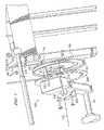
- FIG. 5illustrates an exploded view of the example bidirectional resistance mechanism 100 of FIGS. 1-4 .
- the example shaft 220is implemented as a part of the example selector plate 205 .
- the exercise arm 105 and the example pulleys 210 and 215are mounted to rotate about the shaft 220 .
- the example pulleys 210 and 215are substantially identical and are mounted on the shaft 220 in opposite facing directions as shown in FIG. 5 .
- each of the pulleys 210 and 215has a first protrusion 505 on a first side of the pulley 210 , 215 and a second protrusion 510 on a second side of the pulley 210 , 215 .
- each of the pulleys 210 and 215includes a slot 515 .
- the example slot 515 of a pulley 210 , 215allows the first protrusion 505 of the other pulley 210 , 215 to pass through the pulley 210 , 215 and allows the pulleys 210 and 215 to rotate independently.
- the example protrusions 505are longer than the example protrusions 510 to accommodate the thickness of and/or the space between the example pulleys 210 and 215 .
- the protrusion 505 of the first pulley 210 and the protrusion 510 of the second pulley 215have corresponding stops 525 and 530 that are mounted to the frame member 265 .
- the example stop 525acts against the first protrusion 505 of the first pulley 210 to prevent the first pulley 210 from rotatable clockwise beyond its at rest position
- the example stop 530acts against the second protrusion 510 of the second pulley 215 to prevent the second pulley 215 from rotatable counterclockwise beyond its at rest position.
- FIGS. 6 and 7are views of the example bidirectional resistance mechanism 100 that illustrate how the example selector plate 205 acts to rotate the example pulleys 210 and 215 .
- the example selector plate 205includes stops 605 and 610 .
- the example stop 605acts against the second protrusion 510 of the first pulley 210 causing the first pulley 210 to rotate counterclockwise.
- the example stop 530 mounted to the frame member 265acts against the first protrusion 505 of the second pulley 215 (not shown) to prevent the second pulley 215 from rotating so that the second pulley 215 remains at rest against the stop 530 .
- the selector plate 205is rotated such that the stop 605 is spaced clockwise from the second protrusion 510 of the first pulley 210
- the stop 525 mounted to the frame member 265acts against the first protrusion 505 of the first pulley 210 to prevent the first pulley 210 from rotatable clockwise beyond its at rest position.
- the selector plate 205can similarly engage the example stop 610 against the first protrusion 505 of the second pulley 215 to cause the second pulley 215 to rotate clockwise.
Landscapes
- Health & Medical Sciences (AREA)
- Orthopedic Medicine & Surgery (AREA)
- General Health & Medical Sciences (AREA)
- Physical Education & Sports Medicine (AREA)
- Life Sciences & Earth Sciences (AREA)
- Biophysics (AREA)
- Rehabilitation Tools (AREA)
Abstract
Description
Claims (25)
Priority Applications (1)
| Application Number | Priority Date | Filing Date | Title |
|---|---|---|---|
| US11/625,436US7537551B2 (en) | 2007-01-22 | 2007-01-22 | Bidirectional resistance apparatus for exercise equipment |
Applications Claiming Priority (1)
| Application Number | Priority Date | Filing Date | Title |
|---|---|---|---|
| US11/625,436US7537551B2 (en) | 2007-01-22 | 2007-01-22 | Bidirectional resistance apparatus for exercise equipment |
Publications (2)
| Publication Number | Publication Date |
|---|---|
| US20080176722A1 US20080176722A1 (en) | 2008-07-24 |
| US7537551B2true US7537551B2 (en) | 2009-05-26 |
Family
ID=39641851
Family Applications (1)
| Application Number | Title | Priority Date | Filing Date |
|---|---|---|---|
| US11/625,436Active2027-08-01US7537551B2 (en) | 2007-01-22 | 2007-01-22 | Bidirectional resistance apparatus for exercise equipment |
Country Status (1)
| Country | Link |
|---|---|
| US (1) | US7537551B2 (en) |
Cited By (19)
| Publication number | Priority date | Publication date | Assignee | Title |
|---|---|---|---|---|
| US20080153679A1 (en)* | 2006-12-22 | 2008-06-26 | Stuart Lawrence Shearer | Convertible Gym Training Device And Corresponding Weight-Training Bench |
| US20110098160A1 (en)* | 2008-08-21 | 2011-04-28 | Gil Reyes | Hip flexor |
| KR200463832Y1 (en) | 2010-06-17 | 2012-11-27 | 주식회사 동아스포츠 | Sporting equipment for multi hip-up |
| US9868025B2 (en) | 2015-06-02 | 2018-01-16 | Gymbot, Llc | Contralateral hip and hamstring training device |
| US10173102B2 (en) | 2015-09-08 | 2019-01-08 | Gymbot, Llc | Back machine |
| US10188890B2 (en) | 2013-12-26 | 2019-01-29 | Icon Health & Fitness, Inc. | Magnetic resistance mechanism in a cable machine |
| US10252109B2 (en) | 2016-05-13 | 2019-04-09 | Icon Health & Fitness, Inc. | Weight platform treadmill |
| US10279212B2 (en) | 2013-03-14 | 2019-05-07 | Icon Health & Fitness, Inc. | Strength training apparatus with flywheel and related methods |
| US10293211B2 (en) | 2016-03-18 | 2019-05-21 | Icon Health & Fitness, Inc. | Coordinated weight selection |
| US10426989B2 (en) | 2014-06-09 | 2019-10-01 | Icon Health & Fitness, Inc. | Cable system incorporated into a treadmill |
| US10441840B2 (en) | 2016-03-18 | 2019-10-15 | Icon Health & Fitness, Inc. | Collapsible strength exercise machine |
| US10449416B2 (en) | 2015-08-26 | 2019-10-22 | Icon Health & Fitness, Inc. | Strength exercise mechanisms |
| US10661114B2 (en) | 2016-11-01 | 2020-05-26 | Icon Health & Fitness, Inc. | Body weight lift mechanism on treadmill |
| EP3756735A1 (en) | 2019-06-27 | 2020-12-30 | Life Fitness, LLC | Exercise apparatuses and assemblies facilitating removable attachment of a resistance device to an exercise apparatus |
| US10940360B2 (en) | 2015-08-26 | 2021-03-09 | Icon Health & Fitness, Inc. | Strength exercise mechanisms |
| US20220219036A1 (en)* | 2021-01-13 | 2022-07-14 | Life Fitness, Llc | Bi-directional exercise machines |
| US11648435B2 (en)* | 2019-11-21 | 2023-05-16 | Origins & Insertions Llc | Exercise machine and methods of use for strengthening the lumbopelvic complex |
| US11660499B2 (en)* | 2016-12-05 | 2023-05-30 | Eun Bee Kim | Upper leg and hip exercise method and device to preserve knee and ankle joint while exercising |
| US11660498B2 (en)* | 2016-12-05 | 2023-05-30 | Eun Bee Kim | Upper leg and hip exercise method and device to preserve knee and ankle joint while exercising |
Families Citing this family (14)
| Publication number | Priority date | Publication date | Assignee | Title |
|---|---|---|---|---|
| US7736283B2 (en) | 2006-10-04 | 2010-06-15 | Nautilus, Inc. | Exercise machine having rotatable weight selection index |
| US7775945B2 (en)* | 2004-12-13 | 2010-08-17 | Nautilus, Inc. | Arm assembly for exercise devices |
| US20090118106A1 (en)* | 2007-11-02 | 2009-05-07 | Jayson Leisenring | Exercise machine |
| US20110218083A1 (en)* | 2010-03-02 | 2011-09-08 | David Staff | Upright gluteus isolation weightlifting machine |
| US8845498B2 (en) | 2010-03-31 | 2014-09-30 | Nautilus, Inc. | Lockout mechanism for a weight stack exercise machine |
| US8568279B2 (en) | 2010-03-31 | 2013-10-29 | Nautilus, Inc. | Engagement interface for an exercise machine |
| EP2552554A4 (en) | 2010-03-31 | 2016-09-07 | Nautilus Inc | SELECTABLE WEIGHT STACK |
| US8876665B1 (en)* | 2012-04-30 | 2014-11-04 | Conner Athletic Products | Neck exercise machine for standing use |
| ES2595405T3 (en) | 2012-09-14 | 2016-12-29 | Eccentrica Srl | Apparatus for eccentric stimulation of the hamstrings |
| US9017230B1 (en)* | 2013-03-13 | 2015-04-28 | Desmond Charlton Pitts | Upper body strengthening system |
| US11389694B1 (en) | 2015-03-27 | 2022-07-19 | Aaron Joseph Walker | Rotational and linear resistance force exercise apparatus |
| US10549152B2 (en) | 2015-03-27 | 2020-02-04 | Aaron Joseph Walker | Rotational and linear resistance force exercise apparatus |
| US20160279459A1 (en) | 2015-03-27 | 2016-09-29 | Aaron Joseph Walker | Rotational and linear resistance force exercise apparatus |
| USD1095708S1 (en)* | 2023-12-01 | 2025-09-30 | Yangzhou Jiuyi Hardware & Machinery Co., Ltd. | Exercise machine |
Citations (30)
| Publication number | Priority date | Publication date | Assignee | Title |
|---|---|---|---|---|
| US319686A (en) | 1885-06-09 | faemer | ||
| US3089700A (en)* | 1960-05-24 | 1963-05-14 | Leon G Hotas | Shoulder exercising machines |
| US4456245A (en)* | 1981-12-11 | 1984-06-26 | Nautilus Sports/Medical Industries, Inc. | Rotary torso exercise apparatus |
| US4600189A (en)* | 1984-04-11 | 1986-07-15 | Lifeing, Inc. | Multi-function exercise system |
| US4621807A (en)* | 1984-05-25 | 1986-11-11 | Universal Gym Equipment, Inc. | Leg and hip exercising apparatus |
| US4709919A (en) | 1979-11-13 | 1987-12-01 | Cano Richard A | Exercise machine |
| US4944511A (en) | 1989-01-23 | 1990-07-31 | Paul S. Francis | Adjustable resilient reel exerciser |
| US5058884A (en) | 1990-03-29 | 1991-10-22 | Fuller Sr Barney R | Exercise machine for conditioning football players |
| US5067708A (en) | 1990-06-08 | 1991-11-26 | Lifeing, Inc. | Multi-function exercise system |
| US5102121A (en)* | 1989-02-10 | 1992-04-07 | Lumex, Inc. | Device for limiting the range of motion on weight-lifting machines |
| US5154684A (en) | 1989-06-05 | 1992-10-13 | Delf Eric W | Exercise apparatus for the human body |
| US5190509A (en)* | 1991-09-12 | 1993-03-02 | Davison Jr Fredric O | Upper body isolating exerciser |
| US5242344A (en) | 1990-10-31 | 1993-09-07 | Hundley Kenneth W | Limb movement exercising and training apparatus |
| US5308304A (en) | 1992-07-22 | 1994-05-03 | Pacific Fitness Corporation | Multi-hip exerciser |
| US5380258A (en) | 1992-10-26 | 1995-01-10 | Stairmaster Sports/Medical Products, Inc. | Exercise apparatus |
| US5466204A (en)* | 1994-02-15 | 1995-11-14 | Activeaid, Inc. | Upper body exercise apparatus |
| US5509878A (en) | 1991-01-14 | 1996-04-23 | Denega; Craig | Resist/assist exerciser and its use |
| US5667465A (en)* | 1995-02-07 | 1997-09-16 | Trotter, Inc. | Multidirectional cam |
| US5722921A (en)* | 1997-02-06 | 1998-03-03 | Cybex International, Inc. | Range limiting device for exercise equipment |
| US5810698A (en)* | 1996-04-19 | 1998-09-22 | Nordic Track Inc | Exercise method and apparatus |
| US5885193A (en) | 1997-03-19 | 1999-03-23 | Precor Incorporated | Bi-directional exercise resistance mechanism |
| US6302833B1 (en)* | 2000-01-31 | 2001-10-16 | Northland Industries, Inc. | Multi-function exercise machine |
| US6338701B1 (en) | 1997-11-24 | 2002-01-15 | Randall T. Webber | Cable and puley linkage for exercise machine |
| US20030096681A1 (en) | 2001-11-21 | 2003-05-22 | Icon Ip, Inc. | Exercise machine with dual, cooperating weight stacks |
| US6592498B1 (en) | 1997-03-21 | 2003-07-15 | Patrick John Trainor | Exercise devices |
| US7029426B1 (en) | 2003-02-03 | 2006-04-18 | Fuller Sr Barney R | Exercise machine for conditioning athletes |
| US20060094571A1 (en) | 2004-09-07 | 2006-05-04 | Polidi Richard Z | Mechanical weightlifting machine |
| JP2006122499A (en)* | 2004-10-29 | 2006-05-18 | Senoh Corp | Training machine |
| US20060199708A1 (en) | 2005-03-01 | 2006-09-07 | Technogym S.P.A. | Exercise machine and gripping component thereof |
| US7396319B1 (en)* | 2005-04-08 | 2008-07-08 | Northland Industries, Inc. | Inner and outer thigh exercise machine |
Family Cites Families (1)
| Publication number | Priority date | Publication date | Assignee | Title |
|---|---|---|---|---|
| US6833268B1 (en)* | 1999-06-10 | 2004-12-21 | Abgenix, Inc. | Transgenic animals for producing specific isotypes of human antibodies via non-cognate switch regions |
- 2007
- 2007-01-22USUS11/625,436patent/US7537551B2/enactiveActive
Patent Citations (32)
| Publication number | Priority date | Publication date | Assignee | Title |
|---|---|---|---|---|
| US319686A (en) | 1885-06-09 | faemer | ||
| US3089700A (en)* | 1960-05-24 | 1963-05-14 | Leon G Hotas | Shoulder exercising machines |
| US4709919A (en) | 1979-11-13 | 1987-12-01 | Cano Richard A | Exercise machine |
| US4456245A (en)* | 1981-12-11 | 1984-06-26 | Nautilus Sports/Medical Industries, Inc. | Rotary torso exercise apparatus |
| US4600189A (en)* | 1984-04-11 | 1986-07-15 | Lifeing, Inc. | Multi-function exercise system |
| US4621807A (en)* | 1984-05-25 | 1986-11-11 | Universal Gym Equipment, Inc. | Leg and hip exercising apparatus |
| US4944511A (en) | 1989-01-23 | 1990-07-31 | Paul S. Francis | Adjustable resilient reel exerciser |
| US5102121A (en)* | 1989-02-10 | 1992-04-07 | Lumex, Inc. | Device for limiting the range of motion on weight-lifting machines |
| US5154684A (en) | 1989-06-05 | 1992-10-13 | Delf Eric W | Exercise apparatus for the human body |
| US5058884A (en) | 1990-03-29 | 1991-10-22 | Fuller Sr Barney R | Exercise machine for conditioning football players |
| US5067708A (en) | 1990-06-08 | 1991-11-26 | Lifeing, Inc. | Multi-function exercise system |
| US5242344A (en) | 1990-10-31 | 1993-09-07 | Hundley Kenneth W | Limb movement exercising and training apparatus |
| US5509878A (en) | 1991-01-14 | 1996-04-23 | Denega; Craig | Resist/assist exerciser and its use |
| US5190509A (en)* | 1991-09-12 | 1993-03-02 | Davison Jr Fredric O | Upper body isolating exerciser |
| US5308304A (en) | 1992-07-22 | 1994-05-03 | Pacific Fitness Corporation | Multi-hip exerciser |
| US5354252A (en) | 1992-07-22 | 1994-10-11 | Pacific Fitness Corporation | Multi-hip exerciser |
| US5468202A (en) | 1992-07-22 | 1995-11-21 | Pacific Fitness Corporation | Multi-hip exerciser |
| US5380258A (en) | 1992-10-26 | 1995-01-10 | Stairmaster Sports/Medical Products, Inc. | Exercise apparatus |
| US5466204A (en)* | 1994-02-15 | 1995-11-14 | Activeaid, Inc. | Upper body exercise apparatus |
| US5667465A (en)* | 1995-02-07 | 1997-09-16 | Trotter, Inc. | Multidirectional cam |
| US5810698A (en)* | 1996-04-19 | 1998-09-22 | Nordic Track Inc | Exercise method and apparatus |
| US5722921A (en)* | 1997-02-06 | 1998-03-03 | Cybex International, Inc. | Range limiting device for exercise equipment |
| US5885193A (en) | 1997-03-19 | 1999-03-23 | Precor Incorporated | Bi-directional exercise resistance mechanism |
| US6592498B1 (en) | 1997-03-21 | 2003-07-15 | Patrick John Trainor | Exercise devices |
| US6338701B1 (en) | 1997-11-24 | 2002-01-15 | Randall T. Webber | Cable and puley linkage for exercise machine |
| US6302833B1 (en)* | 2000-01-31 | 2001-10-16 | Northland Industries, Inc. | Multi-function exercise machine |
| US20030096681A1 (en) | 2001-11-21 | 2003-05-22 | Icon Ip, Inc. | Exercise machine with dual, cooperating weight stacks |
| US7029426B1 (en) | 2003-02-03 | 2006-04-18 | Fuller Sr Barney R | Exercise machine for conditioning athletes |
| US20060094571A1 (en) | 2004-09-07 | 2006-05-04 | Polidi Richard Z | Mechanical weightlifting machine |
| JP2006122499A (en)* | 2004-10-29 | 2006-05-18 | Senoh Corp | Training machine |
| US20060199708A1 (en) | 2005-03-01 | 2006-09-07 | Technogym S.P.A. | Exercise machine and gripping component thereof |
| US7396319B1 (en)* | 2005-04-08 | 2008-07-08 | Northland Industries, Inc. | Inner and outer thigh exercise machine |
Cited By (23)
| Publication number | Priority date | Publication date | Assignee | Title |
|---|---|---|---|---|
| US7691038B2 (en)* | 2006-12-22 | 2010-04-06 | Stuart Laurence Shearer | Convertible gym training device and corresponding weight-training bench |
| US20080153679A1 (en)* | 2006-12-22 | 2008-06-26 | Stuart Lawrence Shearer | Convertible Gym Training Device And Corresponding Weight-Training Bench |
| US20110098160A1 (en)* | 2008-08-21 | 2011-04-28 | Gil Reyes | Hip flexor |
| KR200463832Y1 (en) | 2010-06-17 | 2012-11-27 | 주식회사 동아스포츠 | Sporting equipment for multi hip-up |
| US10279212B2 (en) | 2013-03-14 | 2019-05-07 | Icon Health & Fitness, Inc. | Strength training apparatus with flywheel and related methods |
| US10188890B2 (en) | 2013-12-26 | 2019-01-29 | Icon Health & Fitness, Inc. | Magnetic resistance mechanism in a cable machine |
| US10426989B2 (en) | 2014-06-09 | 2019-10-01 | Icon Health & Fitness, Inc. | Cable system incorporated into a treadmill |
| US9868025B2 (en) | 2015-06-02 | 2018-01-16 | Gymbot, Llc | Contralateral hip and hamstring training device |
| US10940360B2 (en) | 2015-08-26 | 2021-03-09 | Icon Health & Fitness, Inc. | Strength exercise mechanisms |
| US10449416B2 (en) | 2015-08-26 | 2019-10-22 | Icon Health & Fitness, Inc. | Strength exercise mechanisms |
| US10173102B2 (en) | 2015-09-08 | 2019-01-08 | Gymbot, Llc | Back machine |
| US10441840B2 (en) | 2016-03-18 | 2019-10-15 | Icon Health & Fitness, Inc. | Collapsible strength exercise machine |
| US10293211B2 (en) | 2016-03-18 | 2019-05-21 | Icon Health & Fitness, Inc. | Coordinated weight selection |
| US10252109B2 (en) | 2016-05-13 | 2019-04-09 | Icon Health & Fitness, Inc. | Weight platform treadmill |
| US10661114B2 (en) | 2016-11-01 | 2020-05-26 | Icon Health & Fitness, Inc. | Body weight lift mechanism on treadmill |
| US11660499B2 (en)* | 2016-12-05 | 2023-05-30 | Eun Bee Kim | Upper leg and hip exercise method and device to preserve knee and ankle joint while exercising |
| US11660498B2 (en)* | 2016-12-05 | 2023-05-30 | Eun Bee Kim | Upper leg and hip exercise method and device to preserve knee and ankle joint while exercising |
| EP3756735A1 (en) | 2019-06-27 | 2020-12-30 | Life Fitness, LLC | Exercise apparatuses and assemblies facilitating removable attachment of a resistance device to an exercise apparatus |
| US11173339B2 (en) | 2019-06-27 | 2021-11-16 | Life Fitness, Llc | Exercise apparatus and assemblies facilitating removable attachment of a resistance device to an exercise apparatus |
| US11648435B2 (en)* | 2019-11-21 | 2023-05-16 | Origins & Insertions Llc | Exercise machine and methods of use for strengthening the lumbopelvic complex |
| US20220219036A1 (en)* | 2021-01-13 | 2022-07-14 | Life Fitness, Llc | Bi-directional exercise machines |
| US11596827B2 (en)* | 2021-01-13 | 2023-03-07 | Life Fitness, Llc | Bi-directional exercise machines |
| US11745048B2 (en) | 2021-01-13 | 2023-09-05 | Life Fitness, Llc | Bi-directional exercise machines |
Also Published As
| Publication number | Publication date |
|---|---|
| US20080176722A1 (en) | 2008-07-24 |
Similar Documents
| Publication | Publication Date | Title |
|---|---|---|
| US7537551B2 (en) | Bidirectional resistance apparatus for exercise equipment | |
| US7396319B1 (en) | Inner and outer thigh exercise machine | |
| TWI320719B (en) | Exercise machine | |
| US6770015B2 (en) | Exercise apparatus with sliding pulley | |
| JP5995878B2 (en) | Improved exercise equipment | |
| US9114275B2 (en) | Exercise assemblies having crank members with limited rotation | |
| US5810698A (en) | Exercise method and apparatus | |
| US7645216B2 (en) | Dual cam exercise device method and apparatus | |
| US8047973B2 (en) | Weightlifting apparatus for pronation and supination exercises | |
| US20140248999A1 (en) | Exercise assemblies having linear motion synchronizing mechanism | |
| WO2006115936A2 (en) | Exercise apparatus | |
| US20080026920A1 (en) | Weightlifting apparatus for pronation and supination exercises | |
| JP2014507239A5 (en) | ||
| WO2000002625A1 (en) | Exercise apparatus | |
| JPH02243170A (en) | Weight lifting training apparatus | |
| US7896777B2 (en) | Multi-dimensional arm and wrist training device capable of changing weight | |
| GB2223686A (en) | Exercise machine | |
| US20240024725A1 (en) | Shoulder strengthening systems | |
| US4725054A (en) | Low inertia counterbalance mechanism | |
| US5769197A (en) | Clutch assembly for an exercise apparatus | |
| US20040005967A1 (en) | Gymnastic apparatus for pectoral muscles | |
| US20200061413A1 (en) | Fitness and Rehabilitation machine for the Rotator Cuff | |
| WO2014195743A1 (en) | Lever with slider | |
| US20220241637A1 (en) | Resistance adjustable exercise device | |
| KR101632273B1 (en) | Exercising Apparatus for the Lower Part |
Legal Events
| Date | Code | Title | Description |
|---|---|---|---|
| AS | Assignment | Owner name:BRUNSWICK CORPORATION, ILLINOIS Free format text:ASSIGNMENT OF ASSIGNORS INTEREST;ASSIGNOR:STEFFEE, CLAY;REEL/FRAME:018836/0157 Effective date:20070121 | |
| STCF | Information on status: patent grant | Free format text:PATENTED CASE | |
| FPAY | Fee payment | Year of fee payment:4 | |
| FEPP | Fee payment procedure | Free format text:PAYOR NUMBER ASSIGNED (ORIGINAL EVENT CODE: ASPN); ENTITY STATUS OF PATENT OWNER: LARGE ENTITY | |
| FPAY | Fee payment | Year of fee payment:8 | |
| AS | Assignment | Owner name:LIFE FITNESS, LLC, ILLINOIS Free format text:ASSIGNMENT OF ASSIGNORS INTEREST;ASSIGNOR:BRUNSWICK CORPORATION;REEL/FRAME:049585/0893 Effective date:20190624 | |
| AS | Assignment | Owner name:PNC BANK, NATIONAL ASSOCIATION, UNITED STATES Free format text:SECURITY AGREEMENT;ASSIGNOR:LIFE FITNESS, LLC;REEL/FRAME:049629/0124 Effective date:20190627 | |
| MAFP | Maintenance fee payment | Free format text:PAYMENT OF MAINTENANCE FEE, 12TH YEAR, LARGE ENTITY (ORIGINAL EVENT CODE: M1553); ENTITY STATUS OF PATENT OWNER: LARGE ENTITY Year of fee payment:12 | |
| AS | Assignment | Owner name:PLC AGENT LLC, AS COLLATERAL AGENT, MASSACHUSETTS Free format text:NOTICE OF GRANT OF SECURITY INTEREST IN PATENTS;ASSIGNOR:LIFE FITNESS, LLC;REEL/FRAME:059861/0208 Effective date:20220415 | |
| AS | Assignment | Owner name:TCW ASSET MANAGEMENT COMPANY LLC, AS COLLATERAL AGENT, MASSACHUSETTS Free format text:SECURITY INTEREST;ASSIGNOR:LIFE FITNESS, LLC;REEL/FRAME:072353/0574 Effective date:20250805 | |
| AS | Assignment | Owner name:LIFE FITNESS, LLC, ILLINOIS Free format text:RELEASE BY SECURED PARTY;ASSIGNOR:PLC AGENT LLC;REEL/FRAME:072363/0759 Effective date:20250805 |