US7537139B2 - Dual chamber piston pressure pack dispenser system - Google Patents
Dual chamber piston pressure pack dispenser systemDownload PDFInfo
- Publication number
- US7537139B2 US7537139B2US11/140,188US14018805AUS7537139B2US 7537139 B2US7537139 B2US 7537139B2US 14018805 AUS14018805 AUS 14018805AUS 7537139 B2US7537139 B2US 7537139B2
- Authority
- US
- United States
- Prior art keywords
- chamber
- dispenser
- region
- flow
- valve member
- Prior art date
- Legal status (The legal status is an assumption and is not a legal conclusion. Google has not performed a legal analysis and makes no representation as to the accuracy of the status listed.)
- Expired - Fee Related, expires
Links
- 230000009977dual effectEffects0.000titleclaimsdescription9
- 230000009969flowable effectEffects0.000claimsabstractdescription32
- 238000002156mixingMethods0.000claimsdescription94
- 239000000463materialSubstances0.000claimsdescription36
- 239000000203mixtureSubstances0.000claimsdescription13
- 239000003380propellantSubstances0.000claimsdescription9
- 238000006073displacement reactionMethods0.000claimsdescription8
- 239000007795chemical reaction productSubstances0.000claimsdescription2
- 239000013070direct materialSubstances0.000claims1
- 239000000047productSubstances0.000description15
- 238000004519manufacturing processMethods0.000description5
- 238000011144upstream manufacturingMethods0.000description5
- 239000000853adhesiveSubstances0.000description4
- 230000001070adhesive effectEffects0.000description4
- 238000006243chemical reactionMethods0.000description4
- 239000002131composite materialSubstances0.000description4
- 239000012530fluidSubstances0.000description4
- 229910052751metalInorganic materials0.000description4
- 239000002184metalSubstances0.000description4
- 239000004033plasticSubstances0.000description4
- 239000000376reactantSubstances0.000description4
- 229910000831SteelInorganic materials0.000description2
- 239000000956alloySubstances0.000description2
- 229910045601alloyInorganic materials0.000description2
- 229910052782aluminiumInorganic materials0.000description2
- XAGFODPZIPBFFR-UHFFFAOYSA-NaluminiumChemical compound[Al]XAGFODPZIPBFFR-UHFFFAOYSA-N0.000description2
- -1for exampleSubstances0.000description2
- 239000007788liquidSubstances0.000description2
- 238000007789sealingMethods0.000description2
- 238000004513sizingMethods0.000description2
- 239000010959steelSubstances0.000description2
- 239000004593EpoxySubstances0.000description1
- 230000003466anti-cipated effectEffects0.000description1
- 239000000356contaminantSubstances0.000description1
- 230000000881depressing effectEffects0.000description1
- 230000000694effectsEffects0.000description1
- 230000001747exhibiting effectEffects0.000description1
- 238000005187foamingMethods0.000description1
- 239000003292glueSubstances0.000description1
- 238000005304joiningMethods0.000description1
- 238000005259measurementMethods0.000description1
- 230000000704physical effectEffects0.000description1
- 238000009877renderingMethods0.000description1
- 238000003860storageMethods0.000description1
- 239000002699waste materialSubstances0.000description1
Images


Classifications
- B—PERFORMING OPERATIONS; TRANSPORTING
- B65—CONVEYING; PACKING; STORING; HANDLING THIN OR FILAMENTARY MATERIAL
- B65D—CONTAINERS FOR STORAGE OR TRANSPORT OF ARTICLES OR MATERIALS, e.g. BAGS, BARRELS, BOTTLES, BOXES, CANS, CARTONS, CRATES, DRUMS, JARS, TANKS, HOPPERS, FORWARDING CONTAINERS; ACCESSORIES, CLOSURES, OR FITTINGS THEREFOR; PACKAGING ELEMENTS; PACKAGES
- B65D81/00—Containers, packaging elements, or packages, for contents presenting particular transport or storage problems, or adapted to be used for non-packaging purposes after removal of contents
- B65D81/32—Containers, packaging elements, or packages, for contents presenting particular transport or storage problems, or adapted to be used for non-packaging purposes after removal of contents for packaging two or more different materials which must be maintained separate prior to use in admixture
- B65D81/325—Containers having parallel or coaxial compartments, provided with a piston or a movable bottom for discharging contents
- B—PERFORMING OPERATIONS; TRANSPORTING
- B05—SPRAYING OR ATOMISING IN GENERAL; APPLYING FLUENT MATERIALS TO SURFACES, IN GENERAL
- B05C—APPARATUS FOR APPLYING FLUENT MATERIALS TO SURFACES, IN GENERAL
- B05C17/00—Hand tools or apparatus using hand held tools, for applying liquids or other fluent materials to, for spreading applied liquids or other fluent materials on, or for partially removing applied liquids or other fluent materials from, surfaces
- B05C17/005—Hand tools or apparatus using hand held tools, for applying liquids or other fluent materials to, for spreading applied liquids or other fluent materials on, or for partially removing applied liquids or other fluent materials from, surfaces for discharging material from a reservoir or container located in or on the hand tool through an outlet orifice by pressure without using surface contacting members like pads or brushes
- B05C17/00553—Hand tools or apparatus using hand held tools, for applying liquids or other fluent materials to, for spreading applied liquids or other fluent materials on, or for partially removing applied liquids or other fluent materials from, surfaces for discharging material from a reservoir or container located in or on the hand tool through an outlet orifice by pressure without using surface contacting members like pads or brushes with means allowing the stock of material to consist of at least two different components
Definitions
- the present inventionrelates to the art of liquid dispensers and, more particularly, to an improved dual chamber dispenser which serves to accurately and simultaneously dispense two or more liquids.
- the present inventionfinds particular utility in connection with the dispensing of fluids and other flowable materials which undergo reaction upon mixing or contact with each other.
- Certain fluid productsare best stored as two separate components to be mixed in selected proportions at the time of use.
- Such productsinclude epoxy type glues, some foaming materials, other adhesive systems and the like.
- certain productshave been sold as consumer products utilizing dual syringes requiring the consumer to hold the syringe and manually depress a dual piston interconnected plunger to dispense two reactants that upon reaction, form the product. The product was generally not mixed and had to be mixed by hand and applied thereafter.
- multi-component reactive systemsoften require administration of the components in unequal proportions. For example, in a two component system, it is often necessary that the components be administered together at a ratio of 1:2 or 3:2 instead of a 1:1 ratio. Although an end user could most likely dispense each respective component in the desired proportion, such obligation further complicates use of a multi-component system, thereby rendering the system less desirable by consumers. Furthermore, manual dispensing of each component in a particular amount, different from the amount of the other component, increases the likelihood of errors in dispensing and thus, results in the administration of incorrect ratios of components.
- multi-component reactive systemscan utilize components that exhibit different flow characteristics, such as viscosity. Attempting to accurately dispense such components, particularly concurrently with one another, is difficult if one component has a relatively low viscosity and thus offers minimal resistance to flow, and another component has a higher viscosity thereby causing that material to exhibit much greater resistance to flow.
- a multi-chamber dispenseris provided by which the foregoing and other problems and disadvantages encountered in connection with the application of two or more fluids, are minimized or overcome.
- the present inventionprovides a dispenser adapted for simultaneously dispensing and mixing at least two flowable components.
- the dispenserincludes at least two containers, each for housing a respective flowable component. Each container defines an interior hollow region and a flow-governing aperture.
- the dispenseralso includes a single valve mixing assembly.
- the assemblyincludes a body defining at least two flow passages, each passage extending between an inlet and a valve receiving region.
- the mixing assemblyalso defines an exit port.
- the mixing assemblyis aligned with, and non-displaceable with respect to, the containers such that a respective inlet is adjacent to an aperture defined in a corresponding container.
- the mixing assemblyfurther includes a valve member disposed in the valve receiving region and positionable between an open state in which flow communication is established between each flow passage and the exit port, and a closed state in which flow communication is blocked between each flow passage and the exit port.
- the present inventionprovides a multi-chamber dispenser comprising a collection of chambers.
- Each chamberhas a first end, a second end opposite from the first end, and a chamber wall extending between the first and second ends. The second end defines an aperture.
- Each chamberdefines an interior hollow region and each chamber includes a piston slidably disposed in the interior hollow region and apportioning the hollow region into a first region proximate the first end, and a second region proximate the second end.
- the dispenseralso comprises a flow body defining a collection of inlet ports. Each inlet port is in flow communication with a corresponding aperture defined in a respective chamber.
- the flow bodyfurther defines an exit port and valve receiving region disposed between and in flow communication with each of the inlet ports and the exit port.
- the dispenseralso comprises a single valve member slidably disposed in the valve receiving region.
- the valve memberincludes an outwardly extending trigger member whereby upon displacement of the trigger member, the valve member is directly displaced between an open position and a closed position.
- the present inventionprovides a dual chamber dispenser comprising a first chamber having a first end, a second end opposite from the first end, and a chamber wall extending between the first and second ends.
- the first chamberdefines an interior hollow region, and the second end defines a flow aperture.
- the dispenseralso comprises a second chamber having a first end, a second end opposite from the first end, and a chamber wall extending between the first and second ends.
- the second chamberdefines an interior hollow region.
- the second enddefines a flow aperture.
- the dispenseralso comprises a first piston slidably disposed in the interior hollow region defined in the first chamber and sealingly contacting the chamber wall of the first chamber.
- the pistondefines a first face and an oppositely directed second face.
- the pistondivides the interior hollow region of the first chamber into a gas region defined between the first end of the first chamber and the first face of the piston, and a flowable material region defined between the second end of the first chamber and the second face of the piston.
- the dispenseralso comprises a second piston slidably disposed in the interior hollow region defined in the second chamber and sealingly contacting the chamber wall of the second chamber.
- the pistondefines a first face and an oppositely directed second face.
- the pistondivides the interior hollow region of the second chamber into a gas region defined between the first end of the second chamber and the first face of the piston, and a flowable material region defined between the second end of the second chamber and the second face of the piston.
- the dispenseralso comprises a mixing body disposed adjacent to the second ends of each of the first and second chambers and non-displaceable with respect to the first and second chambers.
- the mixing bodydefines (i) a valve receiving region, (ii) a first flow passage extending between the flow aperture defined in the first chamber and the valve receiving region, (iii) a second flow passage extending between the flow aperture defined in the second chamber and the valve receiving region, and (iv) an exit port in flow communication with the valve receiving region.
- the dispenserfurther comprises a linearly positionable, non-rotatable valve member slidably disposed within the valve receiving region.
- the valve memberincludes a trigger projection extending outwardly from the first and second chambers.
- the valve memberis selectively positionable between (a) a first open position in which flow communication is established between (i) the first flow passage and the exit port, and (ii) the second flow passage and the exit port, and (b) a closed position in which flow communication is blocked between (i) the first flow passage and the exit port, and (ii) the second flow passage and the exit port.
- the present inventionprovides a dispenser comprising a first chamber having a first end, a second opposite end, and a chamber wall extending therebetween.
- the first chamberdefines an aperture at the first end.
- the dispenseralso comprises a second chamber having a first end, a second opposite end, and a chamber wall extending therebetween.
- the second chamberdefines an aperture at the first end of the second chamber.
- the dispenserfurther comprises a mixing assembly positioned adjacent the first ends of the first and second chambers.
- the mixing assemblydefines (i) a valve receiving region, (ii) a first flow channel extending between the aperture defined at the first end of the first chamber and the valve receiving region, and (iii) a second flow channel extending between the aperture defined at the first end of the second chamber and the valve receiving region.
- the dispenserfurther comprises a single valve member disposed at least partially within the valve receiving region defined in the mixing assembly. The member is positionable between an open position and a closed position. The member defines a distal end which is exposed to both the first flow channel and the second flow channel upon the member being positioned to the open position.
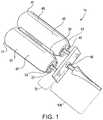
- FIG. 1is a perspective view of a preferred embodiment dispenser according to the present invention.
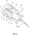
- FIG. 2is a partial sectional perspective view of another preferred embodiment dispenser according to the present invention.
- FIG. 3is a side elevational view of the preferred embodiment dispenser depicted in FIG. 1 .
- FIG. 4is a cross-sectional view of a portion of the preferred embodiment dispenser taken across line 4 - 4 shown in FIG. 3 .
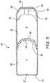
- FIG. 5is a schematic cross-sectional view of a portion of the first chamber taken across line 5 - 5 in FIG. 4 of the preferred embodiment dispenser according to the present invention.
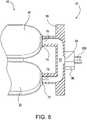
- FIG. 6is a partial sectional schematic view of a portion of the preferred embodiment dispenser according to the present invention.
- FIG. 7is a schematic partial cross section of a preferred embodiment flow nozzle used in the dispenser of the present invention.
- FIG. 8is a schematic view of yet another preferred embodiment dispenser according to the present invention.
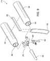
- FIG. 9is an exploded view of the preferred embodiment dispenser illustrated in FIG. 8 .
- FIG. 10is a partial side elevational view of a manifold and trigger assembly of the preferred embodiment dispenser illustrated in FIG. 8 .
- FIG. 11is a partial cross-sectional view of a manifold illustrating a plunger assembly in a closed position in the preferred embodiment dispenser illustrated in FIG. 8 .
- FIG. 12is a partial cross-sectional view of the manifold illustrating the plunger assembly in an open position in the preferred embodiment dispenser shown in FIG. 8 .
- the present inventionprovides a dispenser adapted for accurately dispensing in particular proportions, two or more components and mixing the components prior to their dispensing.
- the dispenseris tailored for dispensing two components of an adhesive system from separate chambers.
- Each chamberis pressurized.
- Each chamberincludes a continuous side wall, two opposite ends with a dispensing valve located in one of the ends.
- a pistonis contained within each chamber separating a pressurized gas volume on one side of the piston and a product volume on the other side of the piston.
- the dispensing valveis opened such as by tilting or depressing the valve stem, the pressurized gas forces the piston outward, thereby dispensing product through the dispensing valve.
- the chambersare preferably rigidly interconnected and can be secured to one another.
- valves closing the ends of the chamberscommunicate with a mixing chamber which in turn communicates with a dispensing nozzle.
- the valvesare preferably interconnected so that opening one valve simultaneously opens the second valve the same amount. In certain versions described herein, a single valve can be used instead of multiple valves.
- the preferred embodiment dispenseralso can be configured to dispense particular components in particular proportions, and dispense components that exhibit physical properties different from one another. For example, such differences might be with regard to viscosity, flow characteristics, or effects exhibited as a result of being at certain temperatures or undergoing particular temperature changes.
- the fluid components of a two component adhesive systemmay differ in viscosity.
- the differences in viscositymay not be linearly related to one another over varying temperature.
- the differences in viscosity and the ratio at which the components are to be combinedare addressed by sizing the orifice through which the individual components are dispensed through the dispensing valve, sizing the relative cross sectional areas of the two chambers, and selecting appropriate pressures and gas mixes for the propellants used in the two chambers.
- the cylindersmay be the same size and the difference in the viscosity may be addressed through adjusting propellant mix.
- one cylindermay have a cross sectional area of 1.5 times the other cylinder
- the valvemay have a similar ratio in cross sectional or orifice area and viscosity differences addressed through propellant mix in the two chambers.
- the components of the adhesiveare mixed in a mixing chamber and, possibly, further mixed in a nozzle having internal mixing vanes.
- FIG. 1illustrates a first preferred embodiment dispenser 10 according to the present invention.
- the dispenser 10comprises a first chamber 20 and a second chamber 40 .
- the first chamber 20defines a first end 21 , a second opposite end 23 , and a chamber wall 25 extending between the two ends.
- the second chamber 40defines a first end 41 , a second opposite end 43 , and a chamber wall 45 extending between the two ends.
- Each of the chambersdefines an interior hollow region.
- the first and second chambersare preferably coupled or otherwise affixed to one another by a coupler 30 which generally extends along the length of each of the first and second chambers 20 , 40 .
- the first chamber 20includes an aperture 22 .
- the second chamber 40includes an aperture 42 .
- the aperture 22is defined in the second end 23 of chamber 20 .
- the aperture 42is defined in the second end 43 of chamber 40 .
- Engaged along the apertured end of the first and second chambersis a mixing assembly 70 .
- the assembly 70is in flow communication with a valve 90 .
- positioned along the distal end of the valve 90is a nozzle 100 .
- the mixing assembly 70 , the valve 90 , and the nozzle 100are described in greater detail herein.
- FIG. 2illustrates an alternate preferred embodiment dispenser 110 according to the present invention.
- the dispenser 110comprises a canister 120 which defines a first chamber 130 and a second chamber 140 within the interior of the canister 120 .
- the first chamber 130defines a first end 131 , a second opposite end 133 , and a chamber wall 135 extending between the two ends.
- the second chamber 140defines a first end 141 , a second opposite end 143 , and a chamber wall 145 extending between the two ends.
- Each of the chambers and canisterincludes an aperture such as first chamber aperture 132 and a second chamber aperture 142 .
- the canister 120can define a generally hollow interior adapted to receive two or more containers which can serve as or otherwise provide chambers.
- the apertured end of the canister 120is adapted to receive the mixing assembly 70 , preferably in association with the valve 90 and the nozzle 100 .
- valve 90located proximate the exit port of a mixing region
- one or more valvescould be utilized upstream of the mixing region, such as for example proximate flow apertures 22 and 42 illustrated in FIG. 1 , or apertures 132 and 142 as depicted in FIG. 2 .
- Utilizing a collection of valves upstream of the mixing regioncan be advantageous in that material flow is controlled with respect to its entry into the mixing region as opposed to its exit from the mixing region.
- each of the chambers used in the preferred embodiment dispensersis cylindrical, the present invention includes the use of other shapes and configurations.
- Each chamberis adapted to contain and maintain an internal pressure greater than atmospheric. Accordingly, the chambers are constructed accordingly and as described in greater detail herein.
- the chamberscan be formed from a wide array of materials however, aluminum, steel, or various alloys thereof are contemplated.
- FIG. 3is a side elevational view of the first preferred embodiment dispenser 10 including the use of an optional handle 32 and an optional trigger member 34 .
- the handle 32generally extends at right angles from the longitudinal axes of the chambers.
- the handlecan be formed from nearly any suitable material, such as for example, metal, plastic, or composites thereof.
- the trigger member 34also preferably extends at right angles to the longitudinal axes of the chambers, and so is generally oriented parallel to the handle 32 .
- the trigger member 34can be engaged with a valve or dispensing component in the mixing assembly 70 as described in greater detail herein.
- the trigger memberis preferably formed from a material similar to that used in forming the handle 32 , e.g.
- the optional handle 32 and trigger member 34are used, they are spaced apart a distance suitable for gripping the handle 32 while contacting the trigger member 34 with one's index finger.
- the present inventionalso includes the use of one of the handle member 32 and the trigger member 34 , without the other.
- FIG. 4is a cross-sectional view taken across lines 4 - 4 in FIG. 3 .
- FIG. 4illustrates the first and second chambers 20 and 40 and the coupler 30 securing the chambers to one another.
- the chamber wall 25defines an interior arcuate surface 26 that forms the interior region of chamber 20 .
- the chamber wall 45defines an interior arcuate surface 46 that forms the interior region of chamber 40 .
- Each of the interior surfaces 26 and 46are preferably finished and adapted to form a seal with a moveable piston slidably positioned within each chamber. And so, upon assembly, the piston sealingly contacts the interior surface of the hollow region in the chamber.
- FIG. 5is a schematic cross-sectional view of a chamber such as the first chamber 20 taken across line 5 - 5 in FIG. 4 .
- a piston 60Disposed within the interior of the chamber is a piston 60 which is slidable therein.
- the pistoncan generally be displaced between one end or region of the chamber 20 and an opposite or distally located region of the chamber 20 .
- an interior first end face 27is defined at the first end 21
- an interior second end face 28 opposite from the first face 27are defined at the ends of the chamber and between which the interior arcuate surface 26 extends.
- the piston 60defines a front face 64 and a rear oppositely directed face 62 .
- the piston 60is slidably disposed between these ends and divides the interior region of the chamber 20 into two portions or regions A and B.
- Portion Ais defined between the first end face 27 , the rear piston face 62 , and the arcuate surface 26 .
- Portion Bis defined between the second end face 28 , the front piston face 64 , and the arcuate surface 26 . It will be understood that as the piston 60 is displaced toward either end 21 or 23 of the chamber, the volume of one portion will increase and the volume of the other portion will decrease accordingly.
- a component to be dispensedresides in portion B and a pressurized gas resides in portion A.
- a receiver body 50is optionally disposed at one end of the chamber 20 and preferably adjacent the aperture 22 .
- the receiver body 50assists in directing flowable component material in portion B toward and through the aperture 22 defined at the end 23 of the chamber.
- the receiver body 50preferably defines a flow conduit 54 that extends through the thickness of the body 50 and provides flow communication between portion B and the aperture 22 .
- the body 50also defines a receiving face surface 52 that exhibits a curvature or other configuration so as to match the curvature or geometry of the front face 64 of the piston 60 .
- FIG. 6is a schematic partial cross-sectional view of the mixing assembly 70 or flow body engaged with the first and second chambers 20 , 40 of the dispenser 10 .
- the mixing assembly 70includes a body 80 which defines a first inlet 72 and a second inlet 74 .
- the bodyalso defines an exit 84 through which material may flow into the valve 90 and eventually to nozzle 100 .
- the body 80defines a first passage 76 generally extending from the first inlet 72 to a mixing region 82 defined proximate the exit 84 .
- the body 80defines a second passage 78 extending from the second inlet 74 to the mixing region 82 .
- FIG. 6is a schematic illustration.
- the mixing region 82is generally larger and defines a greater interior volume than the passages 76 and 78 .
- the interior surfaces defining the passages 76 and 78 , and the mixing region 82are preferably finished and devoid of regions which can trap material flowing from the chambers to the exit 84 .
- the mixing regioncan include one or more internal mixing vanes to promote component mixing within that region.
- FIG. 7is a cross section of the nozzle 100 illustrating a preferred interior configuration.
- nozzle 100includes a nozzle body 106 that defines a first end 108 which engages with an exit port of a mixing assembly, such as 70 , an opposite distal end 110 , and a flow conduit 102 extending between the first end 108 and the distal end 110 .
- a plurality of mixing vanes 104are provided along the flow conduit 102 . The mixing vanes increase turbulence and thus mixing of a flowable material traveling through the conduit 102 .
- FIGS. 8-12illustrate another preferred embodiment dispenser according to the present invention.
- the dispenseruses a single valve assembly for simultaneously dispensing materials from two or more respective containers, simultaneously.
- the use of a single valve assemblyenables a relatively simple and efficient assembly that is economical to manufacture and easy to assemble and use.
- FIGS. 8 and 9illustrate a first preferred embodiment dispenser 210 according to the present invention.
- the dispenser 210comprises a first chamber 220 and a second chamber 240 .
- the first chamber 220defines a first end 221 , a second opposite end 223 , and a chamber wall 225 extending between the two ends.
- the second chamber 240defines a first end 241 , a second opposite end 243 , and a chamber wall 245 extending between the two ends.
- Each of the chambersdefines an interior hollow region.
- the first and second chambersare preferably coupled or otherwise affixed to one another by a coupler 230 which generally extends along the length of each of the first and second chambers 220 , 240 .
- the first chamber 220includes an aperture 222 .
- the second chamber 240includes an aperture 242 .
- the aperture 222is defined in the second end 223 of chamber 220 .
- the aperture 242is defined in the second end 243 of chamber 240 .
- the dispenser 210also includes a handle 232 .
- the handle 232is optional and generally extends at right angles from the longitudinal axes of the chambers.
- the handlecan be formed from nearly any suitable material, such as for example, metal, plastic, or composites thereof.
- Engaged along the apertured end of the first and second chambersis a mixing assembly 270 or flow body.
- the assembly 270is in flow communication with a valve member 290 .
- the valve member 290is engaged with or can be integrally formed with a trigger 292 . And, positioned along the distal end of the valve member 290 is a nozzle 300 .
- the mixing assembly 270 , the valve member 290 , and the nozzle 300are described in greater detail herein.
- valve member 290located proximate the exit port of a mixing region
- one or more valvescould be utilized upstream of the mixing region, such as for example proximate flow apertures 222 and 242 illustrated in FIGS. 8 and 9 .
- Utilizing a collection of valves upstream of the mixing regioncan be advantageous in that material flow can be controlled with respect to its entry into a mixing region as opposed to its exit from the mixing region.
- a significant feature of the dispenser 210is that a single valve, i.e. valve member 290 positionable within the mixing assembly 270 , is used without any valves upstream thereof.
- the dispenser 210is free of valves at the apertures 222 and 242 of the chambers 220 and 240 .
- the use of a single valve in the dispenser 210can lead to relatively low production costs and simplify manufacturing.
- each of the chambers used in the preferred embodiment dispenser 210is cylindrical, the present invention includes the use of other shapes and configurations.
- Each chamberis adapted to contain and maintain an internal pressure greater than atmospheric. Accordingly, the chambers are constructed accordingly and as described in greater detail herein.
- the chamberscan be formed from a wide array of materials however, aluminum, steel, or various alloys thereof are contemplated.
- FIG. 10is a side elevational view of the preferred embodiment dispenser 210 illustrating the use of the trigger member 292 .
- the trigger member 292preferably extends at right angles to the longitudinal axes of the chambers, such as chamber 240 and so is generally oriented parallel to the handle 232 (not shown).
- the trigger member 292is preferably engaged with a valve or dispensing component in the mixing assembly 270 such as valve member 290 as described in greater detail herein.
- the trigger memberis preferably formed from a material similar to that used in forming the handle 232 , e.g. metal, plastic, or composites thereof.
- the valve member 290is displaced or otherwise moved within the mixing assembly 270 by moving the trigger 292 in the directions of the arrows.
- the trigger member 292is engaged with, and preferably directly engaged with, the valve member 290 such that displacement of the trigger member causes concurrent, or substantially so, displacement of the valve member.
- a biasing membersuch as a spring
- a springthat is coupled to the trigger member 292 , can be used to urge the valve member 290 to a normally closed position. This configuration is further described as follows.
- FIGS. 11 and 12are each a schematic partial cross-sectional view of the mixing assembly 270 engaged with the first and second chambers 220 , 240 of the dispenser 210 . These views illustrate positioning the valve member 290 within the mixing assembly 270 .
- the mixing assembly 270includes a body 280 which defines a first inlet 272 and a second inlet 274 .
- the bodyalso defines an exit 284 through which material may flow past the valve member 290 and eventually to nozzle 300 .
- the body 280is positioned relative to the chambers 220 and 240 such that the body defines a first passage 276 generally extending from the first inlet 272 to a mixing region 282 ( FIG. 12 ) defined proximate the exit 284 .
- the body 280defines a second passage 278 extending from the second inlet 274 to the mixing region 282 .
- the body 280also defines a receiving region 285 adapted to sealingly receive the valve member 290 .
- the receiving region 285enables the valve member 290 to move or otherwise be displaced within the region 285 .
- the geometry and configuration of the region 285is preferably matched to the geometry and configuration of the valve member 290 . For example, if the valve member 290 utilizes a circular cross section, then the cross-sectional shape of the opening of the region 285 is also circular.
- the opening of the region 285is sized so as to accommodate displacement of the valve member 290 therein, yet retain a seal therebetween.
- FIG. 11illustrates the valve member 290 in a closed position such that material in either or both of the first and second passages 276 and 278 cannot flow or otherwise travel to the exit 284 .
- FIG. 12illustrates the valve member 290 in an open position such that material in the passages 276 and 278 can flow to the exit 284 , and preferably through the mixing region 282 . It will be appreciated that FIGS. 11 and 12 are schematic illustrations. In practice, the mixing region 282 can be generally larger and define a greater interior volume than the passages 276 and 278 .
- the interior surfaces defining the passages 276 and 278 , and the mixing region 282are preferably finished and devoid of regions which can trap material flowing from the chambers to the exit 284 .
- the mixing regioncan include one or more internal mixing vanes to promote component mixing within that region.
- FIGS. 11 and 12also illustrate a preferred version of the valve member 290 .
- the valve componentdefines two deflection surfaces 291 and 293 at a distal end 295 of the member 290 .
- the deflection surfaces 291 and 293serve to deflect or otherwise guide material in a respective passage 276 to 278 to flow from that passage past the distal end 295 of the valve member 290 , and into the mixing region 285 .
- the deflection surfaces 291 and 293can be in a variety of forms and configurations such as flat surfaces or concave surfaces. It is preferred that the surfaces 291 and 293 each be concave, so as to lessen the extent of energy loss as material flows past the valve member 290 and changes direction in its motion or flow path.
- the various preferred embodiment dispensers described hereincan utilize a number of different features.
- the dispenserscan utilize a mixing assembly or flow body that is generally affixed or secured to one or more of the chambers or containers, or the coupler joining those components.
- the mixing bodyis generally non-displaceable and rigid or fixed with respect to the containers. This is advantageous in that achieving a seal between these components is easier than if the mixing body were positionable or displaceable with respect to the containers.
- valve member and triggerAnother feature of the preferred dispensers relates to the use of an integral valve member and trigger. Although integral is preferred, the present invention includes versions in which the valve member is directly engaged with and coupled to the trigger component. This configuration simplifies assembly and results in less costly manufacturing.
- valve memberbeing slidably disposed in the valve receiving region defined in the mixing body.
- the valve memberis linearly positionable therein, and most preferably non-rotatable once disposed in the valve receiving region. Preventing the valve member from rotating within the receiving region promotes sealing around the member, simplifies assembly and overall manufacture.
- the present invention dispensersinclude the use of multiple valves to govern the discharge or rate of discharge of one or more materials, it is the single valve version that is most preferred.
- the single valve dispensersare more easily manufactured, less expensive, and simpler to operate. Accordingly, widespread commercial appeal is anticipated.
- dispensershave been described in terms of combining, mixing, and dispensing two reactants, each from a separate storage chamber, it will be understood that the present invention includes a dispenser adapted for dispensing three or more reactants or components.
- the present invention dispenserscan be configured to simultaneously dispense components from separate containers and in different, predetermined proportions. Therefore, in addition to dispensing different components at equal proportions, the dispenser can dispense components at different proportions.
- the dispensercan be tailored to dispense components in a wide range of proportions, such as from about 10:1 to about 1:10.
- the particular proportion of each component to be dispensed from its respective container or chambercan be governed by the cross sectional area of the flow passage through which the component flows toward the mixing region.
- a flow governing aperturerepresenting the smallest cross sectional area in the component's flow path is used to govern or control the degree of flow, and particularly, the degree of flow with respect to the other component.
- flow governing aperturesare used to limit or govern the amount or rate of flow of each component.
- the ratio of the cross sectional areas of the apertures defined by the flow governing aperturescorresponds to the desired dispensing ratio of components.
- the ratio of cross sectional area of the flow governing aperture A to the cross sectional area of the flow governing aperture Bis 2:3.
- Each flow governing apertureor rather member defining that aperture, can be positioned anywhere in the flow path of a respective component between the component source and the mixing region. However, it is preferred that the flow governing aperture be disposed at or adjacent to the aperture for the component container or chamber, such as for instance, apertures 22 and 42 in FIG. 1 , or apertures 222 and 242 in FIGS. 8 and 9 .
- the present invention dispenserscan be configured to simultaneously dispense components having different flow characteristics such as viscosity. That is, the present invention dispenser can be tailored to simultaneously dispense a first component having a relatively low viscosity, and thus offering minor resistance to flow, and a second component having a relatively high viscosity, and thus exhibiting a greater resistance to flow.
- each container or chamber housing a componentincludes a movable piston that defines a region for containing a pressurized gas. The higher the pressure of the gas, the greater the force exerted upon the movable piston.
- a flowable component residing on the other side of the pistoncan be displaced at a faster rate from the container by increasing the pressure of the gas residing on the opposite side of the piston.
- components having different viscositiescan be made to dispense at the same rate (assuming the dispensing ratio is 1:1) by using a gas at higher pressure in the chamber containing the higher viscosity component.
- a wide range of pressuresmay be utilized in each chamber.
- the selection of the particular pressure or pressure range for the gas in each containerwill depend upon the viscosity of each component, the difference in the component viscosities, the temperature, and the ratio of the flow governing apertures through which the components are dispensed.
- a specific force or range of forces exerted upon the piston facecan be achieved by utilizing a piston having a face or exposed region with a predetermined cross sectional area.
- the force imparted upon the flowable materialdepends upon the pressure of the gas on the other side of the piston and the cross sectional area of the piston face which is exposed to the gas.
- the present inventionincludes the use of different sized containers or chambers.
Landscapes
- Engineering & Computer Science (AREA)
- Mechanical Engineering (AREA)
- Containers And Packaging Bodies Having A Special Means To Remove Contents (AREA)
- Coating Apparatus (AREA)
Abstract
Description
Claims (30)
Priority Applications (1)
| Application Number | Priority Date | Filing Date | Title |
|---|---|---|---|
| US11/140,188US7537139B2 (en) | 2005-05-27 | 2005-05-27 | Dual chamber piston pressure pack dispenser system |
Applications Claiming Priority (1)
| Application Number | Priority Date | Filing Date | Title |
|---|---|---|---|
| US11/140,188US7537139B2 (en) | 2005-05-27 | 2005-05-27 | Dual chamber piston pressure pack dispenser system |
Publications (2)
| Publication Number | Publication Date |
|---|---|
| US20060266769A1 US20060266769A1 (en) | 2006-11-30 |
| US7537139B2true US7537139B2 (en) | 2009-05-26 |
Family
ID=37462095
Family Applications (1)
| Application Number | Title | Priority Date | Filing Date |
|---|---|---|---|
| US11/140,188Expired - Fee RelatedUS7537139B2 (en) | 2005-05-27 | 2005-05-27 | Dual chamber piston pressure pack dispenser system |
Country Status (1)
| Country | Link |
|---|---|
| US (1) | US7537139B2 (en) |
Cited By (10)
| Publication number | Priority date | Publication date | Assignee | Title |
|---|---|---|---|---|
| US20080129070A1 (en)* | 2006-12-05 | 2008-06-05 | Honda Motor Co., Ltd. | Sealing nozzle and method for producing vehicle body by using the same |
| US20130075427A1 (en)* | 2011-09-28 | 2013-03-28 | Ksaria Corporation | Epoxy dispensing system and dispensing tip used therewith |
| US8596498B2 (en) | 2011-05-02 | 2013-12-03 | Mouse Trap Design, Llc | Mixing and dispensing device |
| US20140117045A1 (en)* | 2012-10-26 | 2014-05-01 | Nordson Corporation | Mixing nozzle assembly having a valve element, fluid dispensing assembly, and related method |
| EP2515785A4 (en)* | 2009-12-22 | 2015-04-08 | 3M Innovative Properties Co | A dispensing device for a dental material and a method of filling the device |
| US9649650B2 (en) | 2013-11-07 | 2017-05-16 | Mouse Trap Design, Llc | Mixing and dispensing device |
| WO2017153199A1 (en) | 2016-03-08 | 2017-09-14 | Gerhard Brugger | Dispenser for dispensing liquid or pasty substances |
| US9949545B2 (en) | 2014-11-26 | 2018-04-24 | L'oreal | Hair coloring appliance |
| US10694832B2 (en) | 2014-12-30 | 2020-06-30 | L'oréal | Hair color system using a smart device |
| US11034508B2 (en)* | 2016-10-24 | 2021-06-15 | Beiersdorf Ag | Multi-component applicator |
Families Citing this family (2)
| Publication number | Priority date | Publication date | Assignee | Title |
|---|---|---|---|---|
| CA2866908C (en) | 2006-12-15 | 2017-09-26 | Jeffrey R. Janssen | Mixing and dispensing curable multi-component materials |
| USD636500S1 (en) | 2008-10-01 | 2011-04-19 | 3M Innovative Properties Company | Dual chamber cartridge |
Citations (62)
| Publication number | Priority date | Publication date | Assignee | Title |
|---|---|---|---|---|
| US2192082A (en) | 1939-02-01 | 1940-02-27 | Paul A Hunicke | Repelling device |
| US3117696A (en) | 1961-07-12 | 1964-01-14 | Cyril J Herman | Gun for two component adhesives |
| US3144966A (en) | 1962-04-16 | 1964-08-18 | Semco Res Inc | Cartridge for mixing and dispensing sealant compound |
| US3166221A (en) | 1961-04-27 | 1965-01-19 | Leo Pharm Prod Ltd | Double-tube dispensing container |
| US3236418A (en) | 1962-11-16 | 1966-02-22 | Oreal | Apparatus for producing constant proportion mixtures of two or more aerosols |
| US3272387A (en) | 1964-10-06 | 1966-09-13 | Pillsbury Co | Selective dispenser |
| US3303970A (en) | 1964-07-14 | 1967-02-14 | Jerome Marrow | Device for simultaneously dispensing from plural sources |
| US3311265A (en) | 1965-06-03 | 1967-03-28 | Chem Dev Corp | Double-barreled dispensing gun |
| US3366290A (en) | 1966-09-08 | 1968-01-30 | Mojonnier Inc | Plastic container with integral handle |
| US3575319A (en) | 1968-07-11 | 1971-04-20 | Upjohn Co | Portable dispenser for polymer foams |
| US3587982A (en) | 1969-01-15 | 1971-06-28 | Ncr Co | Adhesive and sealant dispenser with grinding means |
| US3603487A (en) | 1969-11-17 | 1971-09-07 | Prod Res & Chem Corp | In-line sealant dispenser |
| US3704812A (en) | 1970-06-29 | 1972-12-05 | Ciba Geigy Corp | Multi-component dispenser and valve |
| US3813011A (en) | 1971-05-11 | 1974-05-28 | S Harrison | Aerosol can for dispensing materials in fixed volumetric ratio |
| US4014463A (en) | 1975-11-28 | 1977-03-29 | Kenics Corporation | Plural component dispenser |
| US4040420A (en) | 1976-04-22 | 1977-08-09 | General Dynamics | Packaging and dispensing kit |
| US4159079A (en) | 1977-08-24 | 1979-06-26 | Sealed Air Corporation | Dispenser |
| US4261481A (en) | 1978-08-08 | 1981-04-14 | General Dynamics | Fluid packaging kit for pressurized dispensing |
| US4515296A (en) | 1982-09-23 | 1985-05-07 | Surdilla Silverio B | Variable ratio liquid metering dispenser |
| US4752020A (en) | 1986-05-07 | 1988-06-21 | Franz Grueter | Pressurized dispensing container |
| US4773562A (en) | 1986-09-04 | 1988-09-27 | L'oreal | Dispenser head for mixing separate pasty substances and a storage unit provided with such a dispenser head |
| US4826054A (en) | 1985-10-16 | 1989-05-02 | Rocep Lusol Holdings Limited | Aerosol valve actuator |
| US4880143A (en) | 1988-10-20 | 1989-11-14 | Insta-Foam Products | Dispenser and components for high viscosity foam products |
| US4893729A (en)* | 1988-07-08 | 1990-01-16 | Jerry R. Iggulden | Selectable mixing bottle |
| US4958750A (en) | 1989-11-21 | 1990-09-25 | Two-Part Foam Propellants, Inc. | Disposable foam dispensing apparatus |
| US5005736A (en) | 1987-10-23 | 1991-04-09 | Portas Abelardo A | Apparatus for simultaneously dispensing two components |
| US5009342A (en) | 1989-08-14 | 1991-04-23 | Mark R. Miller | Dual liquid spraying assembly |
| US5040705A (en) | 1988-08-10 | 1991-08-20 | Stoffel Seals Of Canada, Ltd. | Flow control apparatus for container valve |
| US5064098A (en) | 1990-02-23 | 1991-11-12 | Physical Systems, Inc. | Dual component dispenser gun |
| US5092492A (en) | 1990-01-26 | 1992-03-03 | Liquid Control Corporation | Liquid metering, mixing and dispensing gun |
| US5203839A (en) | 1991-06-14 | 1993-04-20 | Skaggs Kenneth R | Apparatus for dispensing adhesive materials |
| US5224629A (en) | 1992-03-19 | 1993-07-06 | Hsich Rong Fuh | Control structure for a pneumatic sealant gun |
| US5244120A (en) | 1992-08-19 | 1993-09-14 | Cp Packaging, Inc. | Dual chamber medicament dispenser |
| US5269441A (en) | 1992-01-31 | 1993-12-14 | Cp Packaging, Inc., Sub. Of Wheaton Industries | Dual chamber medicament dispenser having a pleated common wall |
| US5385270A (en) | 1993-06-29 | 1995-01-31 | Cataneo; Ralph J. | Selectable ratio dispensing apparatus |
| US5386928A (en) | 1993-11-15 | 1995-02-07 | Minnesota Mining And Manufacturing Company | Dual collapsible tube dispensing assembly |
| US5405051A (en) | 1993-09-30 | 1995-04-11 | Miskell; David L. | Two-part aerosol dispenser employing puncturable membranes |
| US5431303A (en) | 1993-09-30 | 1995-07-11 | Miskell; David L. | Two-part aerosol dispenser employing fusible plug |
| US5431307A (en) | 1994-08-26 | 1995-07-11 | Gencorp Inc. | Dispensing plural components |
| US5526957A (en) | 1994-06-23 | 1996-06-18 | Insta-Foam Products, Inc. | Multi-component dispenser with self-pressurization system |
| US5568883A (en) | 1995-04-10 | 1996-10-29 | Innavision Services, Inc. | Apparatus for dispensing two flowable substances in a user selectable ratio |
| US5634571A (en) | 1995-06-07 | 1997-06-03 | Innavision Services, Inc. | Apparatus for dispensing two sprayable substances in a user selectable ratio |
| US5893486A (en) | 1997-05-27 | 1999-04-13 | Liquid Control Corporation | Foam dispensing device |
| US5897539A (en)* | 1995-09-28 | 1999-04-27 | Schering Aktiengesellschaft | Hormone replacement therapy method and hormone dispenser |
| US5901883A (en) | 1995-11-08 | 1999-05-11 | Ing. Erich Pfeiffer Gmbh | Dispenser having nozzle insert with passages for discharge of two media |
| US5944226A (en)* | 1997-06-09 | 1999-08-31 | Liquid Control Corporation | Add-on valve assembly for dual-component cartridge |
| US6012462A (en) | 1999-04-12 | 2000-01-11 | Schmittou; Rodney L | Hand held device for delivering a plurality of hair color formulas to human hair |
| EP1136388A2 (en) | 2000-03-23 | 2001-09-26 | Aerosol-Technik Lindal Gmbh | Dispensing package |
| US6305578B1 (en)* | 1999-02-26 | 2001-10-23 | Wella Aktiengesellshaft | Device for mixing, foaming and dispensing liquids from separate compressed-gas containers |
| US6308863B1 (en) | 1999-09-02 | 2001-10-30 | Owens-Brockway Plastic Products Inc. | Dual chamber package for pressurized products |
| US6340103B1 (en) | 2000-07-18 | 2002-01-22 | Advanced Packaging Corp. | Dispensing mechanism for pressurized container |
| US6343718B1 (en) | 1998-10-15 | 2002-02-05 | Loctite Corporation | Unit dose dispense package |
| US6422427B1 (en) | 1998-03-20 | 2002-07-23 | Liquid Control Corp | Dispensing tool and system for reloading the tool |
| US20020130141A1 (en) | 2001-02-01 | 2002-09-19 | Dispensing Technologies International Corporation (Dtic) | Fluid dispenser particularly adapted for hand-held operation |
| US6474510B2 (en) | 1997-10-07 | 2002-11-05 | Rocep Lusol Holdings Limited | Dispensing apparatus |
| US20030071081A1 (en) | 2001-10-05 | 2003-04-17 | Aerosol-Technik Lindal Gmbh | Valve assembly for pressurized fluid containers |
| US20030075571A1 (en) | 1999-11-17 | 2003-04-24 | The Gillette Company, A Delaware Corporation | Hand-held product dispensers having pressurized delivery |
| US6685064B2 (en) | 1999-12-30 | 2004-02-03 | Rocep Lusol Holdings Limited | Dispensing apparatus |
| US20040065691A1 (en) | 2000-11-03 | 2004-04-08 | Vilmos Weiperth | Packaging unit for the storage and dispensing of liquids, fluid and ductile materials |
| US20040188465A1 (en) | 2003-03-28 | 2004-09-30 | Timmerman Mark S. | Stabilizing cap for dual-compartment adhesive dispensing cartridge |
| US20040195266A1 (en) | 2003-01-30 | 2004-10-07 | Maeda Corporation | Mixing tube and method of manufacturing the mixing tube |
| US20040251275A1 (en) | 2002-12-06 | 2004-12-16 | Stephen Sams | Mixing and dispensing device comprising multiple pressurized containers |
- 2005
- 2005-05-27USUS11/140,188patent/US7537139B2/ennot_activeExpired - Fee Related
Patent Citations (62)
| Publication number | Priority date | Publication date | Assignee | Title |
|---|---|---|---|---|
| US2192082A (en) | 1939-02-01 | 1940-02-27 | Paul A Hunicke | Repelling device |
| US3166221A (en) | 1961-04-27 | 1965-01-19 | Leo Pharm Prod Ltd | Double-tube dispensing container |
| US3117696A (en) | 1961-07-12 | 1964-01-14 | Cyril J Herman | Gun for two component adhesives |
| US3144966A (en) | 1962-04-16 | 1964-08-18 | Semco Res Inc | Cartridge for mixing and dispensing sealant compound |
| US3236418A (en) | 1962-11-16 | 1966-02-22 | Oreal | Apparatus for producing constant proportion mixtures of two or more aerosols |
| US3303970A (en) | 1964-07-14 | 1967-02-14 | Jerome Marrow | Device for simultaneously dispensing from plural sources |
| US3272387A (en) | 1964-10-06 | 1966-09-13 | Pillsbury Co | Selective dispenser |
| US3311265A (en) | 1965-06-03 | 1967-03-28 | Chem Dev Corp | Double-barreled dispensing gun |
| US3366290A (en) | 1966-09-08 | 1968-01-30 | Mojonnier Inc | Plastic container with integral handle |
| US3575319A (en) | 1968-07-11 | 1971-04-20 | Upjohn Co | Portable dispenser for polymer foams |
| US3587982A (en) | 1969-01-15 | 1971-06-28 | Ncr Co | Adhesive and sealant dispenser with grinding means |
| US3603487A (en) | 1969-11-17 | 1971-09-07 | Prod Res & Chem Corp | In-line sealant dispenser |
| US3704812A (en) | 1970-06-29 | 1972-12-05 | Ciba Geigy Corp | Multi-component dispenser and valve |
| US3813011A (en) | 1971-05-11 | 1974-05-28 | S Harrison | Aerosol can for dispensing materials in fixed volumetric ratio |
| US4014463A (en) | 1975-11-28 | 1977-03-29 | Kenics Corporation | Plural component dispenser |
| US4040420A (en) | 1976-04-22 | 1977-08-09 | General Dynamics | Packaging and dispensing kit |
| US4159079A (en) | 1977-08-24 | 1979-06-26 | Sealed Air Corporation | Dispenser |
| US4261481A (en) | 1978-08-08 | 1981-04-14 | General Dynamics | Fluid packaging kit for pressurized dispensing |
| US4515296A (en) | 1982-09-23 | 1985-05-07 | Surdilla Silverio B | Variable ratio liquid metering dispenser |
| US4826054A (en) | 1985-10-16 | 1989-05-02 | Rocep Lusol Holdings Limited | Aerosol valve actuator |
| US4752020A (en) | 1986-05-07 | 1988-06-21 | Franz Grueter | Pressurized dispensing container |
| US4773562A (en) | 1986-09-04 | 1988-09-27 | L'oreal | Dispenser head for mixing separate pasty substances and a storage unit provided with such a dispenser head |
| US5005736A (en) | 1987-10-23 | 1991-04-09 | Portas Abelardo A | Apparatus for simultaneously dispensing two components |
| US4893729A (en)* | 1988-07-08 | 1990-01-16 | Jerry R. Iggulden | Selectable mixing bottle |
| US5040705A (en) | 1988-08-10 | 1991-08-20 | Stoffel Seals Of Canada, Ltd. | Flow control apparatus for container valve |
| US4880143A (en) | 1988-10-20 | 1989-11-14 | Insta-Foam Products | Dispenser and components for high viscosity foam products |
| US5009342A (en) | 1989-08-14 | 1991-04-23 | Mark R. Miller | Dual liquid spraying assembly |
| US4958750A (en) | 1989-11-21 | 1990-09-25 | Two-Part Foam Propellants, Inc. | Disposable foam dispensing apparatus |
| US5092492A (en) | 1990-01-26 | 1992-03-03 | Liquid Control Corporation | Liquid metering, mixing and dispensing gun |
| US5064098A (en) | 1990-02-23 | 1991-11-12 | Physical Systems, Inc. | Dual component dispenser gun |
| US5203839A (en) | 1991-06-14 | 1993-04-20 | Skaggs Kenneth R | Apparatus for dispensing adhesive materials |
| US5269441A (en) | 1992-01-31 | 1993-12-14 | Cp Packaging, Inc., Sub. Of Wheaton Industries | Dual chamber medicament dispenser having a pleated common wall |
| US5224629A (en) | 1992-03-19 | 1993-07-06 | Hsich Rong Fuh | Control structure for a pneumatic sealant gun |
| US5244120A (en) | 1992-08-19 | 1993-09-14 | Cp Packaging, Inc. | Dual chamber medicament dispenser |
| US5385270A (en) | 1993-06-29 | 1995-01-31 | Cataneo; Ralph J. | Selectable ratio dispensing apparatus |
| US5431303A (en) | 1993-09-30 | 1995-07-11 | Miskell; David L. | Two-part aerosol dispenser employing fusible plug |
| US5405051A (en) | 1993-09-30 | 1995-04-11 | Miskell; David L. | Two-part aerosol dispenser employing puncturable membranes |
| US5386928A (en) | 1993-11-15 | 1995-02-07 | Minnesota Mining And Manufacturing Company | Dual collapsible tube dispensing assembly |
| US5526957A (en) | 1994-06-23 | 1996-06-18 | Insta-Foam Products, Inc. | Multi-component dispenser with self-pressurization system |
| US5431307A (en) | 1994-08-26 | 1995-07-11 | Gencorp Inc. | Dispensing plural components |
| US5568883A (en) | 1995-04-10 | 1996-10-29 | Innavision Services, Inc. | Apparatus for dispensing two flowable substances in a user selectable ratio |
| US5634571A (en) | 1995-06-07 | 1997-06-03 | Innavision Services, Inc. | Apparatus for dispensing two sprayable substances in a user selectable ratio |
| US5897539A (en)* | 1995-09-28 | 1999-04-27 | Schering Aktiengesellschaft | Hormone replacement therapy method and hormone dispenser |
| US5901883A (en) | 1995-11-08 | 1999-05-11 | Ing. Erich Pfeiffer Gmbh | Dispenser having nozzle insert with passages for discharge of two media |
| US5893486A (en) | 1997-05-27 | 1999-04-13 | Liquid Control Corporation | Foam dispensing device |
| US5944226A (en)* | 1997-06-09 | 1999-08-31 | Liquid Control Corporation | Add-on valve assembly for dual-component cartridge |
| US6474510B2 (en) | 1997-10-07 | 2002-11-05 | Rocep Lusol Holdings Limited | Dispensing apparatus |
| US6422427B1 (en) | 1998-03-20 | 2002-07-23 | Liquid Control Corp | Dispensing tool and system for reloading the tool |
| US6343718B1 (en) | 1998-10-15 | 2002-02-05 | Loctite Corporation | Unit dose dispense package |
| US6305578B1 (en)* | 1999-02-26 | 2001-10-23 | Wella Aktiengesellshaft | Device for mixing, foaming and dispensing liquids from separate compressed-gas containers |
| US6012462A (en) | 1999-04-12 | 2000-01-11 | Schmittou; Rodney L | Hand held device for delivering a plurality of hair color formulas to human hair |
| US6308863B1 (en) | 1999-09-02 | 2001-10-30 | Owens-Brockway Plastic Products Inc. | Dual chamber package for pressurized products |
| US20030075571A1 (en) | 1999-11-17 | 2003-04-24 | The Gillette Company, A Delaware Corporation | Hand-held product dispensers having pressurized delivery |
| US6685064B2 (en) | 1999-12-30 | 2004-02-03 | Rocep Lusol Holdings Limited | Dispensing apparatus |
| EP1136388A2 (en) | 2000-03-23 | 2001-09-26 | Aerosol-Technik Lindal Gmbh | Dispensing package |
| US6340103B1 (en) | 2000-07-18 | 2002-01-22 | Advanced Packaging Corp. | Dispensing mechanism for pressurized container |
| US20040065691A1 (en) | 2000-11-03 | 2004-04-08 | Vilmos Weiperth | Packaging unit for the storage and dispensing of liquids, fluid and ductile materials |
| US20020130141A1 (en) | 2001-02-01 | 2002-09-19 | Dispensing Technologies International Corporation (Dtic) | Fluid dispenser particularly adapted for hand-held operation |
| US20030071081A1 (en) | 2001-10-05 | 2003-04-17 | Aerosol-Technik Lindal Gmbh | Valve assembly for pressurized fluid containers |
| US20040251275A1 (en) | 2002-12-06 | 2004-12-16 | Stephen Sams | Mixing and dispensing device comprising multiple pressurized containers |
| US20040195266A1 (en) | 2003-01-30 | 2004-10-07 | Maeda Corporation | Mixing tube and method of manufacturing the mixing tube |
| US20040188465A1 (en) | 2003-03-28 | 2004-09-30 | Timmerman Mark S. | Stabilizing cap for dual-compartment adhesive dispensing cartridge |
Non-Patent Citations (4)
| Title |
|---|
| LePage Products, Loctite Power Grab May Make Hammers Obsolete, 2 pages, Aug. 2004, at http://www.lepageproducts.com/detail.asp?PID=292. |
| Lindal Dual Action Power Can, Lindal Goup, at www.lindalgroup.com. |
| Lindal Group, Dispensing Systems, Nov. 2004, at http://www.lindalgroup.com/en.product.php?id=78. |
| Loctite Consumer Retail Products/Product Detail, Power Grab Construction Adhesives, 2 pages, Aug. 2004, at http://www.loctiteproducts.com/products/detail.as?catid=45&subid=113&plid=474. |
Cited By (14)
| Publication number | Priority date | Publication date | Assignee | Title |
|---|---|---|---|---|
| US20080129070A1 (en)* | 2006-12-05 | 2008-06-05 | Honda Motor Co., Ltd. | Sealing nozzle and method for producing vehicle body by using the same |
| US20170265969A1 (en)* | 2009-12-22 | 2017-09-21 | 3M Innovative Properties Company | Dispensing device for a dental material and a method of filling the device |
| EP2515785A4 (en)* | 2009-12-22 | 2015-04-08 | 3M Innovative Properties Co | A dispensing device for a dental material and a method of filling the device |
| US8596498B2 (en) | 2011-05-02 | 2013-12-03 | Mouse Trap Design, Llc | Mixing and dispensing device |
| US9180476B2 (en) | 2011-05-02 | 2015-11-10 | Mouse Trap Design, Llc | Mixing and dispensing device |
| US20130075427A1 (en)* | 2011-09-28 | 2013-03-28 | Ksaria Corporation | Epoxy dispensing system and dispensing tip used therewith |
| US9239428B2 (en)* | 2011-09-28 | 2016-01-19 | Ksaria Corporation | Epoxy dispensing system and dispensing tip used therewith |
| US20140117045A1 (en)* | 2012-10-26 | 2014-05-01 | Nordson Corporation | Mixing nozzle assembly having a valve element, fluid dispensing assembly, and related method |
| US9649650B2 (en) | 2013-11-07 | 2017-05-16 | Mouse Trap Design, Llc | Mixing and dispensing device |
| US9949545B2 (en) | 2014-11-26 | 2018-04-24 | L'oreal | Hair coloring appliance |
| US10694832B2 (en) | 2014-12-30 | 2020-06-30 | L'oréal | Hair color system using a smart device |
| WO2017153199A1 (en) | 2016-03-08 | 2017-09-14 | Gerhard Brugger | Dispenser for dispensing liquid or pasty substances |
| DE102016104190A1 (en) | 2016-03-08 | 2017-09-14 | Gerhard Brugger | Dispenser for the dispensing of liquid or pasty substances |
| US11034508B2 (en)* | 2016-10-24 | 2021-06-15 | Beiersdorf Ag | Multi-component applicator |
Also Published As
| Publication number | Publication date |
|---|---|
| US20060266769A1 (en) | 2006-11-30 |
Similar Documents
| Publication | Publication Date | Title |
|---|---|---|
| US7537139B2 (en) | Dual chamber piston pressure pack dispenser system | |
| AU760146B2 (en) | Device for mixing, foaming and dispensing liquids from separate compressed-gas containers | |
| US6161729A (en) | Dual chamber dispenser | |
| US6375096B1 (en) | Two component spray gun and nozzle attachment | |
| US6299023B1 (en) | Device for dispensing two substances in a user selectable ratio with replaceable cartridges | |
| US8596498B2 (en) | Mixing and dispensing device | |
| US9254954B2 (en) | Metering valve | |
| US8083103B2 (en) | Dispenser with dual pump system | |
| US5901883A (en) | Dispenser having nozzle insert with passages for discharge of two media | |
| AU680357B2 (en) | Metering device for dispensing constant unit doses | |
| US8328120B2 (en) | Actuator for a receptacle having a pressurized content and method for spraying a pressurized content | |
| AU2011292152B2 (en) | High flow aerosol valve | |
| US6923342B2 (en) | Systems for dispensing multi-component products | |
| WO2006037112A3 (en) | Laterally-actuated dispenser with one- way valve for storing and dispensing metered amounts of substances | |
| CA2429685A1 (en) | Foam forming unit | |
| US20020038826A1 (en) | Two-component dispensing gun | |
| EP3515582B1 (en) | Mixer assembly and device for dispensing a dental material | |
| JP6654706B2 (en) | Background of Invention of Single Acting Dispenser with Sliding Sleeve with Plug | |
| CN101873894A (en) | Fluid dispensing nozzle | |
| US9079197B2 (en) | Dual polymer needles for disposable foam dispensing gun | |
| CA2227377A1 (en) | Multi-part dispenser | |
| US6991185B2 (en) | Multi-component foam dispenser with improved flow metering means | |
| US3606963A (en) | Aerosol dispenser for dispensing a multicomponent product | |
| EP0803449A1 (en) | Improvements in or relating to valve for dispensers | |
| US4368832A (en) | Fluid dispensing valve having a deformable diaphragm |
Legal Events
| Date | Code | Title | Description |
|---|---|---|---|
| AS | Assignment | Owner name:HENKEL CONSUMER ADHESIVES, INC., OHIO Free format text:ASSIGNMENT OF ASSIGNORS INTEREST;ASSIGNORS:JACKSON, SCOTT;TERHARDT, MICHAEL;REEL/FRAME:016622/0188;SIGNING DATES FROM 20050408 TO 20050512 | |
| AS | Assignment | Owner name:HENKEL CORPORATION,PENNSYLVANIA Free format text:MERGER;ASSIGNOR:HENKEL CONSUMER ADHESIVES, INC.;REEL/FRAME:018815/0115 Effective date:20061215 Owner name:HENKEL CORPORATION, PENNSYLVANIA Free format text:MERGER;ASSIGNOR:HENKEL CONSUMER ADHESIVES, INC.;REEL/FRAME:018815/0115 Effective date:20061215 | |
| FPAY | Fee payment | Year of fee payment:4 | |
| AS | Assignment | Owner name:HENKEL US IP LLC, CONNECTICUT Free format text:ASSIGNMENT OF ASSIGNORS INTEREST;ASSIGNOR:HENKEL CORPORATION;REEL/FRAME:034184/0396 Effective date:20141106 | |
| AS | Assignment | Owner name:HENKEL IP & HOLDING GMBH, GERMANY Free format text:ASSIGNMENT OF ASSIGNORS INTEREST;ASSIGNOR:HENKEL US IP LLC;REEL/FRAME:035100/0776 Effective date:20150225 | |
| REMI | Maintenance fee reminder mailed | ||
| LAPS | Lapse for failure to pay maintenance fees | ||
| STCH | Information on status: patent discontinuation | Free format text:PATENT EXPIRED DUE TO NONPAYMENT OF MAINTENANCE FEES UNDER 37 CFR 1.362 | |
| FP | Lapsed due to failure to pay maintenance fee | Effective date:20170526 |