US7535991B2 - Portable orthovoltage radiotherapy - Google Patents
Portable orthovoltage radiotherapyDownload PDFInfo
- Publication number
- US7535991B2 US7535991B2US11/879,843US87984307AUS7535991B2US 7535991 B2US7535991 B2US 7535991B2US 87984307 AUS87984307 AUS 87984307AUS 7535991 B2US7535991 B2US 7535991B2
- Authority
- US
- United States
- Prior art keywords
- eye
- ray
- radiation
- emitter
- patient
- Prior art date
- Legal status (The legal status is an assumption and is not a legal conclusion. Google has not performed a legal analysis and makes no representation as to the accuracy of the status listed.)
- Expired - Fee Related, expires
Links
- 238000001959radiotherapyMethods0.000titleabstractdescription121
- 230000005855radiationEffects0.000claimsabstractdescription143
- 238000003384imaging methodMethods0.000claimsabstractdescription42
- 238000011282treatmentMethods0.000claimsdescription184
- 210000003786scleraAnatomy0.000claimsdescription60
- 206010025421MaculeDiseases0.000claimsdescription25
- 210000004087corneaAnatomy0.000claimsdescription19
- 210000003128headAnatomy0.000claimsdescription12
- 210000004872soft tissueAnatomy0.000claimsdescription5
- 239000002775capsuleSubstances0.000claimsdescription4
- 210000001585trabecular meshworkAnatomy0.000claimsdescription4
- 210000000845cartilageAnatomy0.000claimsdescription3
- 210000001061foreheadAnatomy0.000claimsdescription3
- 208000002780macular degenerationDiseases0.000abstractdescription29
- 208000022873Ocular diseaseDiseases0.000abstractdescription9
- 230000002757inflammatory effectEffects0.000abstractdescription5
- 238000011287therapeutic doseMethods0.000abstractdescription5
- 210000001508eyeAnatomy0.000description396
- 210000001525retinaAnatomy0.000description84
- 238000000034methodMethods0.000description67
- 210000000695crystalline lenAnatomy0.000description52
- 238000002560therapeutic procedureMethods0.000description36
- 238000004088simulationMethods0.000description24
- 208000037265diseases, disorders, signs and symptomsDiseases0.000description23
- 230000033001locomotionEffects0.000description21
- 210000001328optic nerveAnatomy0.000description21
- 230000008878couplingEffects0.000description18
- 238000010168coupling processMethods0.000description18
- 238000005859coupling reactionMethods0.000description18
- 201000010099diseaseDiseases0.000description18
- 210000001519tissueAnatomy0.000description14
- 239000003795chemical substances by applicationSubstances0.000description13
- 239000003814drugSubstances0.000description12
- 230000000694effectsEffects0.000description12
- 238000000342Monte Carlo simulationMethods0.000description11
- 206010064930age-related macular degenerationDiseases0.000description11
- 239000000463materialSubstances0.000description10
- 208000010412GlaucomaDiseases0.000description9
- 108010073929Vascular Endothelial Growth Factor AProteins0.000description9
- 102000005789Vascular Endothelial Growth FactorsHuman genes0.000description9
- 108010019530Vascular Endothelial Growth FactorsProteins0.000description9
- 238000013461designMethods0.000description9
- 230000008685targetingEffects0.000description9
- 108091008605VEGF receptorsProteins0.000description8
- 210000003484anatomyAnatomy0.000description8
- 238000001914filtrationMethods0.000description8
- 230000004054inflammatory processEffects0.000description8
- 102000009484Vascular Endothelial Growth Factor ReceptorsHuman genes0.000description7
- 229910052782aluminiumInorganic materials0.000description7
- XAGFODPZIPBFFR-UHFFFAOYSA-NaluminiumChemical compound[Al]XAGFODPZIPBFFR-UHFFFAOYSA-N0.000description7
- 230000008901benefitEffects0.000description7
- 238000002725brachytherapyMethods0.000description7
- 238000005259measurementMethods0.000description7
- 230000037390scarringEffects0.000description7
- 238000001356surgical procedureMethods0.000description7
- 230000000007visual effectEffects0.000description7
- XLYOFNOQVPJJNP-UHFFFAOYSA-NwaterSubstancesOXLYOFNOQVPJJNP-UHFFFAOYSA-N0.000description7
- 206010029113NeovascularisationDiseases0.000description6
- 238000001816coolingMethods0.000description6
- 230000006378damageEffects0.000description6
- 229940079593drugDrugs0.000description6
- 238000002647laser therapyMethods0.000description6
- 238000012014optical coherence tomographyMethods0.000description6
- 238000007493shaping processMethods0.000description6
- WFKWXMTUELFFGS-UHFFFAOYSA-NtungstenChemical compound[W]WFKWXMTUELFFGS-UHFFFAOYSA-N0.000description6
- 229910052721tungstenInorganic materials0.000description6
- 239000010937tungstenSubstances0.000description6
- 206010061218InflammationDiseases0.000description5
- 206010038923RetinopathyDiseases0.000description5
- 208000000208Wet Macular DegenerationDiseases0.000description5
- 208000035475disorderDiseases0.000description5
- 230000004424eye movementEffects0.000description5
- 230000003902lesionEffects0.000description5
- 229910052760oxygenInorganic materials0.000description5
- 239000001301oxygenSubstances0.000description5
- 230000035515penetrationEffects0.000description5
- 238000001228spectrumMethods0.000description5
- 230000001225therapeutic effectEffects0.000description5
- 238000002604ultrasonographyMethods0.000description5
- 206010028980NeoplasmDiseases0.000description4
- QVGXLLKOCUKJST-UHFFFAOYSA-Natomic oxygenChemical compound[O]QVGXLLKOCUKJST-UHFFFAOYSA-N0.000description4
- 238000004891communicationMethods0.000description4
- 238000010438heat treatmentMethods0.000description4
- 210000004379membraneAnatomy0.000description4
- 239000012528membraneSubstances0.000description4
- 229910052751metalInorganic materials0.000description4
- 239000002184metalSubstances0.000description4
- 210000003205muscleAnatomy0.000description4
- 230000003287optical effectEffects0.000description4
- 230000008569processEffects0.000description4
- 238000012545processingMethods0.000description4
- 210000001747pupilAnatomy0.000description4
- 230000002207retinal effectEffects0.000description4
- 201000004569BlindnessDiseases0.000description3
- 208000002177CataractDiseases0.000description3
- 208000003556Dry Eye SyndromesDiseases0.000description3
- 206010013774Dry eyeDiseases0.000description3
- 206010073306Exposure to radiationDiseases0.000description3
- 238000010521absorption reactionMethods0.000description3
- 238000009098adjuvant therapyMethods0.000description3
- 239000005557antagonistSubstances0.000description3
- 210000002159anterior chamberAnatomy0.000description3
- 230000009286beneficial effectEffects0.000description3
- 210000000988bone and boneAnatomy0.000description3
- 210000003161choroidAnatomy0.000description3
- 210000004240ciliary bodyAnatomy0.000description3
- 238000002591computed tomographyMethods0.000description3
- 210000000795conjunctivaAnatomy0.000description3
- 238000001514detection methodMethods0.000description3
- 208000011325dry age related macular degenerationDiseases0.000description3
- 230000005670electromagnetic radiationEffects0.000description3
- 230000036541healthEffects0.000description3
- 229910001385heavy metalInorganic materials0.000description3
- 208000015181infectious diseaseDiseases0.000description3
- 239000000314lubricantSubstances0.000description3
- 238000002595magnetic resonance imagingMethods0.000description3
- 230000007246mechanismEffects0.000description3
- 238000002428photodynamic therapyMethods0.000description3
- 239000002464receptor antagonistSubstances0.000description3
- 229940044551receptor antagonistDrugs0.000description3
- 229940124597therapeutic agentDrugs0.000description3
- 230000004393visual impairmentEffects0.000description3
- CIWBSHSKHKDKBQ-JLAZNSOCSA-NAscorbic acidChemical compoundOC[C@H](O)[C@H]1OC(=O)C(O)=C1OCIWBSHSKHKDKBQ-JLAZNSOCSA-N0.000description2
- 206010012689Diabetic retinopathyDiseases0.000description2
- XEEYBQQBJWHFJM-UHFFFAOYSA-NIronChemical compound[Fe]XEEYBQQBJWHFJM-UHFFFAOYSA-N0.000description2
- ZOKXTWBITQBERF-UHFFFAOYSA-NMolybdenumChemical compound[Mo]ZOKXTWBITQBERF-UHFFFAOYSA-N0.000description2
- PXHVJJICTQNCMI-UHFFFAOYSA-NNickelChemical compound[Ni]PXHVJJICTQNCMI-UHFFFAOYSA-N0.000description2
- 238000009825accumulationMethods0.000description2
- 239000004037angiogenesis inhibitorSubstances0.000description2
- 238000011122anti-angiogenic therapyMethods0.000description2
- 230000000340anti-metaboliteEffects0.000description2
- 229940100197antimetaboliteDrugs0.000description2
- 239000002256antimetaboliteSubstances0.000description2
- 229960000397bevacizumabDrugs0.000description2
- 230000027455bindingEffects0.000description2
- 230000015572biosynthetic processEffects0.000description2
- 210000004556brainAnatomy0.000description2
- 210000000481breastAnatomy0.000description2
- 238000004422calculation algorithmMethods0.000description2
- 210000004027cellAnatomy0.000description2
- 230000001886ciliary effectEffects0.000description2
- 230000001427coherent effectEffects0.000description2
- 238000002648combination therapyMethods0.000description2
- 150000001875compoundsChemical class0.000description2
- 238000011347external beam therapyMethods0.000description2
- 238000007667floatingMethods0.000description2
- 239000012530fluidSubstances0.000description2
- 238000005194fractionationMethods0.000description2
- 239000007943implantSubstances0.000description2
- 230000002458infectious effectEffects0.000description2
- 230000002401inhibitory effectEffects0.000description2
- 208000014674injuryDiseases0.000description2
- 230000003993interactionEffects0.000description2
- 230000004807localizationEffects0.000description2
- 239000003550markerSubstances0.000description2
- 229910052750molybdenumInorganic materials0.000description2
- 239000011733molybdenumSubstances0.000description2
- 230000003472neutralizing effectEffects0.000description2
- 230000001575pathological effectEffects0.000description2
- 230000003537radioprotectorEffects0.000description2
- 208000014733refractive errorDiseases0.000description2
- 238000009877renderingMethods0.000description2
- 230000008439repair processEffects0.000description2
- 239000000523sampleSubstances0.000description2
- 210000003625skullAnatomy0.000description2
- 231100000331toxicToxicity0.000description2
- 230000002588toxic effectEffects0.000description2
- 230000008733traumaEffects0.000description2
- 229940121358tyrosine kinase inhibitorDrugs0.000description2
- 239000005483tyrosine kinase inhibitorSubstances0.000description2
- 230000004304visual acuityEffects0.000description2
- 238000012800visualizationMethods0.000description2
- GVJHHUAWPYXKBD-IEOSBIPESA-Nα-tocopherolChemical compoundOC1=C(C)C(C)=C2O[C@@](CCC[C@H](C)CCC[C@H](C)CCCC(C)C)(C)CCC2=C1CGVJHHUAWPYXKBD-IEOSBIPESA-N0.000description2
- QCHFTSOMWOSFHM-WPRPVWTQSA-N(+)-PilocarpineChemical compoundC1OC(=O)[C@@H](CC)[C@H]1CC1=CN=CN1CQCHFTSOMWOSFHM-WPRPVWTQSA-N0.000description1
- WAVYAFBQOXCGSZ-UHFFFAOYSA-N2-fluoropyrimidineChemical compoundFC1=NC=CC=N1WAVYAFBQOXCGSZ-UHFFFAOYSA-N0.000description1
- GAGWJHPBXLXJQN-UORFTKCHSA-NCapecitabineChemical compoundC1=C(F)C(NC(=O)OCCCCC)=NC(=O)N1[C@H]1[C@H](O)[C@H](O)[C@@H](C)O1GAGWJHPBXLXJQN-UORFTKCHSA-N0.000description1
- GAGWJHPBXLXJQN-UHFFFAOYSA-NCapecitabineNatural productsC1=C(F)C(NC(=O)OCCCCC)=NC(=O)N1C1C(O)C(O)C(C)O1GAGWJHPBXLXJQN-UHFFFAOYSA-N0.000description1
- 206010010741ConjunctivitisDiseases0.000description1
- RYGMFSIKBFXOCR-UHFFFAOYSA-NCopperChemical compound[Cu]RYGMFSIKBFXOCR-UHFFFAOYSA-N0.000description1
- 101710112752CytotoxinProteins0.000description1
- ZZZCUOFIHGPKAK-UHFFFAOYSA-ND-erythro-ascorbic acidNatural productsOCC1OC(=O)C(O)=C1OZZZCUOFIHGPKAK-UHFFFAOYSA-N0.000description1
- 229940123780DNA topoisomerase I inhibitorDrugs0.000description1
- 230000004568DNA-bindingEffects0.000description1
- 206010012688Diabetic retinal oedemaDiseases0.000description1
- 102000001301EGF receptorHuman genes0.000description1
- 108060006698EGF receptorProteins0.000description1
- GHASVSINZRGABV-UHFFFAOYSA-NFluorouracilChemical compoundFC1=CNC(=O)NC1=OGHASVSINZRGABV-UHFFFAOYSA-N0.000description1
- 229910052688GadoliniumInorganic materials0.000description1
- 208000008069Geographic AtrophyDiseases0.000description1
- 206010020843HyperthermiaDiseases0.000description1
- 206010021143HypoxiaDiseases0.000description1
- ZDZOTLJHXYCWBA-VCVYQWHSSA-NN-debenzoyl-N-(tert-butoxycarbonyl)-10-deacetyltaxolChemical compoundO([C@H]1[C@H]2[C@@](C([C@H](O)C3=C(C)[C@@H](OC(=O)[C@H](O)[C@@H](NC(=O)OC(C)(C)C)C=4C=CC=CC=4)C[C@]1(O)C3(C)C)=O)(C)[C@@H](O)C[C@H]1OC[C@]12OC(=O)C)C(=O)C1=CC=CC=C1ZDZOTLJHXYCWBA-VCVYQWHSSA-N0.000description1
- 206010033799ParalysisDiseases0.000description1
- BYPFEZZEUUWMEJ-UHFFFAOYSA-NPentoxifyllineChemical compoundO=C1N(CCCCC(=O)C)C(=O)N(C)C2=C1N(C)C=N2BYPFEZZEUUWMEJ-UHFFFAOYSA-N0.000description1
- 208000018262Peripheral vascular diseaseDiseases0.000description1
- OAICVXFJPJFONN-UHFFFAOYSA-NPhosphorusChemical compound[P]OAICVXFJPJFONN-UHFFFAOYSA-N0.000description1
- 206010036346Posterior capsule opacificationDiseases0.000description1
- 208000035965Postoperative ComplicationsDiseases0.000description1
- QCHFTSOMWOSFHM-UHFFFAOYSA-NSJ000285536Natural productsC1OC(=O)C(CC)C1CC1=CN=CN1CQCHFTSOMWOSFHM-UHFFFAOYSA-N0.000description1
- 208000000453Skin NeoplasmsDiseases0.000description1
- 229940123237TaxaneDrugs0.000description1
- 241000278713TheoraSpecies0.000description1
- 239000000365Topoisomerase I InhibitorSubstances0.000description1
- 108060008682Tumor Necrosis FactorProteins0.000description1
- 102100033177Vascular endothelial growth factor receptor 2Human genes0.000description1
- 229930003268Vitamin CNatural products0.000description1
- 238000002083X-ray spectrumMethods0.000description1
- AREUQFTVCMGENT-UAKXSSHOSA-N[[(2r,3s,4r,5r)-5-(5-fluoro-2,4-dioxopyrimidin-1-yl)-3,4-dihydroxyoxolan-2-yl]methoxy-hydroxyphosphoryl] phosphono hydrogen phosphateChemical compoundO1[C@H](COP(O)(=O)OP(O)(=O)OP(O)(O)=O)[C@@H](O)[C@@H](O)[C@@H]1N1C(=O)NC(=O)C(F)=C1AREUQFTVCMGENT-UAKXSSHOSA-N0.000description1
- 230000004913activationEffects0.000description1
- OENHQHLEOONYIE-UKMVMLAPSA-Nall-trans beta-caroteneNatural productsCC=1CCCC(C)(C)C=1/C=C/C(/C)=C/C=C/C(/C)=C/C=C/C=C(C)C=CC=C(C)C=CC1=C(C)CCCC1(C)COENHQHLEOONYIE-UKMVMLAPSA-N0.000description1
- 229940087168alpha tocopherolDrugs0.000description1
- JKOQGQFVAUAYPM-UHFFFAOYSA-NamifostineChemical compoundNCCCNCCSP(O)(O)=OJKOQGQFVAUAYPM-UHFFFAOYSA-N0.000description1
- 229960001097amifostineDrugs0.000description1
- 238000004458analytical methodMethods0.000description1
- 229940124599anti-inflammatory drugDrugs0.000description1
- 230000003110anti-inflammatory effectEffects0.000description1
- 230000002137anti-vascular effectEffects0.000description1
- 239000002246antineoplastic agentSubstances0.000description1
- 239000003963antioxidant agentSubstances0.000description1
- 235000006708antioxidantsNutrition0.000description1
- 238000013459approachMethods0.000description1
- TUPZEYHYWIEDIH-WAIFQNFQSA-Nbeta-caroteneNatural productsCC(=C/C=C/C=C(C)/C=C/C=C(C)/C=C/C1=C(C)CCCC1(C)C)C=CC=C(/C)C=CC2=CCCCC2(C)CTUPZEYHYWIEDIH-WAIFQNFQSA-N0.000description1
- 235000013734beta-caroteneNutrition0.000description1
- 239000011648beta-caroteneSubstances0.000description1
- 229960002747betacaroteneDrugs0.000description1
- 239000008280bloodSubstances0.000description1
- 210000004369bloodAnatomy0.000description1
- 210000004204blood vesselAnatomy0.000description1
- 230000015624blood vessel developmentEffects0.000description1
- 210000000746body regionAnatomy0.000description1
- 210000001775bruch membraneAnatomy0.000description1
- 238000004364calculation methodMethods0.000description1
- 229960004117capecitabineDrugs0.000description1
- 229960004562carboplatinDrugs0.000description1
- 190000008236carboplatinChemical compound0.000description1
- 150000005829chemical entitiesChemical class0.000description1
- 238000002512chemotherapyMethods0.000description1
- 230000001684chronic effectEffects0.000description1
- DQLATGHUWYMOKM-UHFFFAOYSA-LcisplatinChemical compoundN[Pt](N)(Cl)ClDQLATGHUWYMOKM-UHFFFAOYSA-L0.000description1
- 229960004316cisplatinDrugs0.000description1
- 238000011281clinical therapyMethods0.000description1
- 150000004814combretastatinsChemical class0.000description1
- 238000005094computer simulationMethods0.000description1
- 239000012809cooling fluidSubstances0.000description1
- 229910052802copperInorganic materials0.000description1
- 239000010949copperSubstances0.000description1
- 239000003255cyclooxygenase 2 inhibitorSubstances0.000description1
- 230000001120cytoprotective effectEffects0.000description1
- 231100000433cytotoxicToxicity0.000description1
- 231100000599cytotoxic agentToxicity0.000description1
- 230000001472cytotoxic effectEffects0.000description1
- 239000002619cytotoxinSubstances0.000description1
- 230000003247decreasing effectEffects0.000description1
- 230000001419dependent effectEffects0.000description1
- 230000008021depositionEffects0.000description1
- 206010012601diabetes mellitusDiseases0.000description1
- 201000011190diabetic macular edemaDiseases0.000description1
- 238000003745diagnosisMethods0.000description1
- 229960003668docetaxelDrugs0.000description1
- 235000012489doughnutsNutrition0.000description1
- 230000007783downstream signalingEffects0.000description1
- 229940121647egfr inhibitorDrugs0.000description1
- 238000005516engineering processMethods0.000description1
- 230000002708enhancing effectEffects0.000description1
- 208000024519eye neoplasmDiseases0.000description1
- 230000004438eyesightEffects0.000description1
- 230000001815facial effectEffects0.000description1
- 239000000835fiberSubstances0.000description1
- 229960002949fluorouracilDrugs0.000description1
- 238000009472formulationMethods0.000description1
- 230000006870functionEffects0.000description1
- 238000002599functional magnetic resonance imagingMethods0.000description1
- UIWYJDYFSGRHKR-UHFFFAOYSA-Ngadolinium atomChemical compound[Gd]UIWYJDYFSGRHKR-UHFFFAOYSA-N0.000description1
- 229960005277gemcitabineDrugs0.000description1
- SDUQYLNIPVEERB-QPPQHZFASA-NgemcitabineChemical compoundO=C1N=C(N)C=CN1[C@H]1C(F)(F)[C@H](O)[C@@H](CO)O1SDUQYLNIPVEERB-QPPQHZFASA-N0.000description1
- 210000004392genitaliaAnatomy0.000description1
- PCHJSUWPFVWCPO-UHFFFAOYSA-NgoldChemical compound[Au]PCHJSUWPFVWCPO-UHFFFAOYSA-N0.000description1
- 230000012010growthEffects0.000description1
- 230000002962histologic effectEffects0.000description1
- 210000004276hyalinAnatomy0.000description1
- 230000036031hyperthermiaEffects0.000description1
- 230000001146hypoxic effectEffects0.000description1
- 208000027866inflammatory diseaseDiseases0.000description1
- 239000003112inhibitorSubstances0.000description1
- 230000005764inhibitory processEffects0.000description1
- 238000011835investigationMethods0.000description1
- 230000005865ionizing radiationEffects0.000description1
- 229960004768irinotecanDrugs0.000description1
- UWKQSNNFCGGAFS-XIFFEERXSA-NirinotecanChemical compoundC1=C2C(CC)=C3CN(C(C4=C([C@@](C(=O)OC4)(O)CC)C=4)=O)C=4C3=NC2=CC=C1OC(=O)N(CC1)CCC1N1CCCCC1UWKQSNNFCGGAFS-XIFFEERXSA-N0.000description1
- 229910052742ironInorganic materials0.000description1
- 210000001503jointAnatomy0.000description1
- 239000011133leadSubstances0.000description1
- 210000003644lens cellAnatomy0.000description1
- 239000003446ligandSubstances0.000description1
- 230000000670limiting effectEffects0.000description1
- 230000007257malfunctionEffects0.000description1
- 230000001404mediated effectEffects0.000description1
- 201000001441melanomaDiseases0.000description1
- 238000010197meta-analysisMethods0.000description1
- 150000002739metalsChemical class0.000description1
- 238000000386microscopyMethods0.000description1
- 239000000203mixtureSubstances0.000description1
- 238000012986modificationMethods0.000description1
- 230000004048modificationEffects0.000description1
- 239000003607modifierSubstances0.000description1
- 230000009854mucosal lesionEffects0.000description1
- 210000000282nailAnatomy0.000description1
- 210000003739neckAnatomy0.000description1
- 210000004126nerve fiberAnatomy0.000description1
- 229910052759nickelInorganic materials0.000description1
- 201000008106ocular cancerDiseases0.000description1
- 230000000771oncological effectEffects0.000description1
- 238000011275oncology therapyMethods0.000description1
- 238000012634optical imagingMethods0.000description1
- 238000005457optimizationMethods0.000description1
- 230000036961partial effectEffects0.000description1
- 230000000149penetrating effectEffects0.000description1
- 230000007903penetration abilityEffects0.000description1
- 229960001476pentoxifyllineDrugs0.000description1
- 230000002093peripheral effectEffects0.000description1
- 238000012831peritoneal equilibrium testMethods0.000description1
- 230000000649photocoagulationEffects0.000description1
- 229960001416pilocarpineDrugs0.000description1
- 150000003057platinumChemical class0.000description1
- 238000012636positron electron tomographyMethods0.000description1
- 238000012877positron emission topographyMethods0.000description1
- 201000010041presbyopiaDiseases0.000description1
- 238000002203pretreatmentMethods0.000description1
- 230000002265preventionEffects0.000description1
- 230000035755proliferationEffects0.000description1
- 210000002307prostateAnatomy0.000description1
- 230000004224protectionEffects0.000description1
- 230000001681protective effectEffects0.000description1
- 230000009979protective mechanismEffects0.000description1
- 150000003230pyrimidinesChemical class0.000description1
- 238000002673radiosurgeryMethods0.000description1
- 230000007115recruitmentEffects0.000description1
- 230000000452restraining effectEffects0.000description1
- 238000012552reviewMethods0.000description1
- 230000036573scar formationEffects0.000description1
- 230000019491signal transductionEffects0.000description1
- 238000004513sizingMethods0.000description1
- 206010040882skin lesionDiseases0.000description1
- 231100000444skin lesionToxicity0.000description1
- 150000003384small moleculesChemical class0.000description1
- 230000003595spectral effectEffects0.000description1
- 238000011272standard treatmentMethods0.000description1
- 150000003431steroidsChemical class0.000description1
- 229910052712strontiumInorganic materials0.000description1
- CIOAGBVUUVVLOB-UHFFFAOYSA-Nstrontium atomChemical compound[Sr]CIOAGBVUUVVLOB-UHFFFAOYSA-N0.000description1
- MNQYNQBOVCBZIQ-JQOFMKNESA-AsucralfateChemical compoundO[Al](O)OS(=O)(=O)O[C@@H]1[C@@H](OS(=O)(=O)O[Al](O)O)[C@H](OS(=O)(=O)O[Al](O)O)[C@@H](COS(=O)(=O)O[Al](O)O)O[C@H]1O[C@@]1(COS(=O)(=O)O[Al](O)O)[C@@H](OS(=O)(=O)O[Al](O)O)[C@H](OS(=O)(=O)O[Al](O)O)[C@@H](OS(=O)(=O)O[Al](O)O)O1MNQYNQBOVCBZIQ-JQOFMKNESA-A0.000description1
- 229960004291sucralfateDrugs0.000description1
- 238000009121systemic therapyMethods0.000description1
- -1taxanesChemical compound0.000description1
- 210000002435tendonAnatomy0.000description1
- 238000000015thermotherapyMethods0.000description1
- 150000003573thiolsChemical class0.000description1
- 230000019432tissue deathEffects0.000description1
- 229960000984tocofersolanDrugs0.000description1
- 238000012876topographyMethods0.000description1
- 231100000133toxic exposureToxicity0.000description1
- 231100000419toxicityToxicity0.000description1
- 230000001988toxicityEffects0.000description1
- 238000012546transferMethods0.000description1
- 235000011178triphosphateNutrition0.000description1
- 239000001226triphosphateSubstances0.000description1
- UNXRWKVEANCORM-UHFFFAOYSA-Ntriphosphoric acidChemical compoundOP(O)(=O)OP(O)(=O)OP(O)(O)=OUNXRWKVEANCORM-UHFFFAOYSA-N0.000description1
- 102000003390tumor necrosis factorHuman genes0.000description1
- 238000012285ultrasound imagingMethods0.000description1
- 238000009424underpinningMethods0.000description1
- XGOYIMQSIKSOBS-UHFFFAOYSA-NvadimezanChemical compoundC1=CC=C2C(=O)C3=CC=C(C)C(C)=C3OC2=C1CC(O)=OXGOYIMQSIKSOBS-UHFFFAOYSA-N0.000description1
- 238000010200validation analysisMethods0.000description1
- 230000002792vascularEffects0.000description1
- 210000005166vasculatureAnatomy0.000description1
- 238000012795verificationMethods0.000description1
- 239000011782vitaminSubstances0.000description1
- 229940088594vitaminDrugs0.000description1
- 229930003231vitaminNatural products0.000description1
- 235000013343vitaminNutrition0.000description1
- 235000019154vitamin CNutrition0.000description1
- 239000011718vitamin CSubstances0.000description1
- 210000004127vitreous bodyAnatomy0.000description1
- 230000029663wound healingEffects0.000description1
- 239000002076α-tocopherolSubstances0.000description1
- 235000004835α-tocopherolNutrition0.000description1
- OENHQHLEOONYIE-JLTXGRSLSA-Nβ-CaroteneChemical compoundCC=1CCCC(C)(C)C=1\C=C\C(\C)=C\C=C\C(\C)=C\C=C\C=C(/C)\C=C\C=C(/C)\C=C\C1=C(C)CCCC1(C)COENHQHLEOONYIE-JLTXGRSLSA-N0.000description1
Images


Classifications
- A—HUMAN NECESSITIES
- A61—MEDICAL OR VETERINARY SCIENCE; HYGIENE
- A61N—ELECTROTHERAPY; MAGNETOTHERAPY; RADIATION THERAPY; ULTRASOUND THERAPY
- A61N5/00—Radiation therapy
- A61N5/10—X-ray therapy; Gamma-ray therapy; Particle-irradiation therapy
- A61N5/1048—Monitoring, verifying, controlling systems and methods
- A61N5/1049—Monitoring, verifying, controlling systems and methods for verifying the position of the patient with respect to the radiation beam
- A—HUMAN NECESSITIES
- A61—MEDICAL OR VETERINARY SCIENCE; HYGIENE
- A61F—FILTERS IMPLANTABLE INTO BLOOD VESSELS; PROSTHESES; DEVICES PROVIDING PATENCY TO, OR PREVENTING COLLAPSING OF, TUBULAR STRUCTURES OF THE BODY, e.g. STENTS; ORTHOPAEDIC, NURSING OR CONTRACEPTIVE DEVICES; FOMENTATION; TREATMENT OR PROTECTION OF EYES OR EARS; BANDAGES, DRESSINGS OR ABSORBENT PADS; FIRST-AID KITS
- A61F9/00—Methods or devices for treatment of the eyes; Devices for putting in contact-lenses; Devices to correct squinting; Apparatus to guide the blind; Protective devices for the eyes, carried on the body or in the hand
- A61F9/007—Methods or devices for eye surgery
- A—HUMAN NECESSITIES
- A61—MEDICAL OR VETERINARY SCIENCE; HYGIENE
- A61B—DIAGNOSIS; SURGERY; IDENTIFICATION
- A61B5/00—Measuring for diagnostic purposes; Identification of persons
- A—HUMAN NECESSITIES
- A61—MEDICAL OR VETERINARY SCIENCE; HYGIENE
- A61B—DIAGNOSIS; SURGERY; IDENTIFICATION
- A61B6/00—Apparatus or devices for radiation diagnosis; Apparatus or devices for radiation diagnosis combined with radiation therapy equipment
- A61B6/50—Apparatus or devices for radiation diagnosis; Apparatus or devices for radiation diagnosis combined with radiation therapy equipment specially adapted for specific body parts; specially adapted for specific clinical applications
- A61B6/506—Apparatus or devices for radiation diagnosis; Apparatus or devices for radiation diagnosis combined with radiation therapy equipment specially adapted for specific body parts; specially adapted for specific clinical applications for diagnosis of nerves
- A—HUMAN NECESSITIES
- A61—MEDICAL OR VETERINARY SCIENCE; HYGIENE
- A61F—FILTERS IMPLANTABLE INTO BLOOD VESSELS; PROSTHESES; DEVICES PROVIDING PATENCY TO, OR PREVENTING COLLAPSING OF, TUBULAR STRUCTURES OF THE BODY, e.g. STENTS; ORTHOPAEDIC, NURSING OR CONTRACEPTIVE DEVICES; FOMENTATION; TREATMENT OR PROTECTION OF EYES OR EARS; BANDAGES, DRESSINGS OR ABSORBENT PADS; FIRST-AID KITS
- A61F9/00—Methods or devices for treatment of the eyes; Devices for putting in contact-lenses; Devices to correct squinting; Apparatus to guide the blind; Protective devices for the eyes, carried on the body or in the hand
- A61F9/007—Methods or devices for eye surgery
- A61F9/008—Methods or devices for eye surgery using laser
- A61F9/009—Auxiliary devices making contact with the eyeball and coupling in laser light, e.g. goniolenses
- A—HUMAN NECESSITIES
- A61—MEDICAL OR VETERINARY SCIENCE; HYGIENE
- A61N—ELECTROTHERAPY; MAGNETOTHERAPY; RADIATION THERAPY; ULTRASOUND THERAPY
- A61N5/00—Radiation therapy
- A61N5/10—X-ray therapy; Gamma-ray therapy; Particle-irradiation therapy
- A—HUMAN NECESSITIES
- A61—MEDICAL OR VETERINARY SCIENCE; HYGIENE
- A61N—ELECTROTHERAPY; MAGNETOTHERAPY; RADIATION THERAPY; ULTRASOUND THERAPY
- A61N5/00—Radiation therapy
- A61N5/10—X-ray therapy; Gamma-ray therapy; Particle-irradiation therapy
- A61N5/1001—X-ray therapy; Gamma-ray therapy; Particle-irradiation therapy using radiation sources introduced into or applied onto the body; brachytherapy
- A61N5/1014—Intracavitary radiation therapy
- A61N5/1017—Treatment of the eye, e.g. for "macular degeneration"
- A—HUMAN NECESSITIES
- A61—MEDICAL OR VETERINARY SCIENCE; HYGIENE
- A61B—DIAGNOSIS; SURGERY; IDENTIFICATION
- A61B17/00—Surgical instruments, devices or methods
- A61B17/30—Surgical pincettes, i.e. surgical tweezers without pivotal connections
- A61B2017/306—Surgical pincettes, i.e. surgical tweezers without pivotal connections holding by means of suction
- A—HUMAN NECESSITIES
- A61—MEDICAL OR VETERINARY SCIENCE; HYGIENE
- A61N—ELECTROTHERAPY; MAGNETOTHERAPY; RADIATION THERAPY; ULTRASOUND THERAPY
- A61N5/00—Radiation therapy
- A61N5/10—X-ray therapy; Gamma-ray therapy; Particle-irradiation therapy
- A61N5/1048—Monitoring, verifying, controlling systems and methods
- A61N5/1049—Monitoring, verifying, controlling systems and methods for verifying the position of the patient with respect to the radiation beam
- A61N2005/105—Monitoring, verifying, controlling systems and methods for verifying the position of the patient with respect to the radiation beam using a laser alignment system
- A—HUMAN NECESSITIES
- A61—MEDICAL OR VETERINARY SCIENCE; HYGIENE
- A61N—ELECTROTHERAPY; MAGNETOTHERAPY; RADIATION THERAPY; ULTRASOUND THERAPY
- A61N5/00—Radiation therapy
- A61N5/10—X-ray therapy; Gamma-ray therapy; Particle-irradiation therapy
- A61N5/1048—Monitoring, verifying, controlling systems and methods
- A61N5/1049—Monitoring, verifying, controlling systems and methods for verifying the position of the patient with respect to the radiation beam
- A61N2005/1056—Monitoring, verifying, controlling systems and methods for verifying the position of the patient with respect to the radiation beam by projecting a visible image of the treatment field
- A—HUMAN NECESSITIES
- A61—MEDICAL OR VETERINARY SCIENCE; HYGIENE
- A61N—ELECTROTHERAPY; MAGNETOTHERAPY; RADIATION THERAPY; ULTRASOUND THERAPY
- A61N5/00—Radiation therapy
- A61N5/10—X-ray therapy; Gamma-ray therapy; Particle-irradiation therapy
- A61N2005/1085—X-ray therapy; Gamma-ray therapy; Particle-irradiation therapy characterised by the type of particles applied to the patient
- A61N2005/1091—Kilovoltage or orthovoltage range photons
- A—HUMAN NECESSITIES
- A61—MEDICAL OR VETERINARY SCIENCE; HYGIENE
- A61N—ELECTROTHERAPY; MAGNETOTHERAPY; RADIATION THERAPY; ULTRASOUND THERAPY
- A61N5/00—Radiation therapy
- A61N5/10—X-ray therapy; Gamma-ray therapy; Particle-irradiation therapy
- A61N5/103—Treatment planning systems
Definitions
- This disclosurerelates to the treatment of ocular disorders using targeted photon energy.
- the present disclosurerelates to an apparatus, systems, and methods for image-guided low energy x-ray therapy of ocular structures.
- Macular degenerationis a condition where the light-sensing cells of the macula, a near-center portion of the retina of the human eye, malfunction and slowly cease to work. Macular degeneration is the leading cause of central vision loss in people over the age of fifty years. Clinical and histologic evidence indicates that macular degeneration is in part caused or results in an inflammatory process which ultimately causes destruction of the retina. The inflammatory process can result in direct destruction of the retina or destruction via formation of neovascular membranes which leak fluid and blood into the retina, quickly leading to scarring.
- Treatments for macular degenerationinclude the use of medication injected directly into the eye (Anti-VEGF therapy), laser therapy in combination with a targeting drug (photodynamic therapy); other treatments include brachytherapy (the local application of a material which generates beta-radiation).
- a radiotherapy systemmay be used to treat a wide variety of medical conditions relating to the eye.
- the systemmay be used, alone or in combination with other therapies, to treat macular degeneration, diabetic retinopathy, inflammatory retinopathies, infectious retinopathies, tumors in the eye or around the eye, glaucoma, refractive disorders, cataracts, post-surgical inflammation of any of the structures of the eye, ptyrigium, and dry eye.
- radiotherapy(or externally applied radiation therapy) is used for treatment of macular degeneration, and a standard treatment for macular degeneration is disclosed.
- Radiotherapy for treatment of macular degenerationpresents several complications.
- the eyecontains several critical structures, such as the lens and the optic nerve, that can possibly be damaged by excessive exposure to radiation.
- the application of external beam therapyis limited by devices and methodologies used to apply the therapy. These devices and methodologies are older radiation technologies used to treat conditions such as tumors anywhere in the body and were not developed specifically for ocular radiation therapy.
- logisticsare difficult as far as patient recruitment and administration of treatments because such treatment devices are borrowed from and displace oncologic therapies.
- Retinal radiotherapy trialshave shown stabilized or improved visual acuity without any significant toxicity. Radiation has also been shown to dry up neovascular membranes in patients and stabilize vision.
- retinal radiotherapyoften irradiates the entire retina, which is both unnecessary and possibly harmful.
- Brachytherapy for wet AMDis also a powerful therapy to treat wet AMD (Neovista, Inc., Press Release, March 2007, the entirety of which is incorporated herein by reference).
- a major limitation of this treatmentis that it requires invasive procedures involving partial removal of the vitreous fluid of the posterior chamber of the eye to place the brachytherapy probe. In addition, it cannot be fractionated because of the invasiveness required to deliver it. Furthermore, it would be difficult to apply this therapy to patients who do not yet have vision loss because of the potential complications from the procedure.
- glaucomaOther diseases of the eye include glaucoma.
- surgeryis often the second line of therapy after pharmaceutical therapy.
- Proceduressuch as trabeculoplasty, trabeculotomy, canaloplasty, laser iridotomy, placement of shunts, and other procedures all suffer from a short-lived effect because of scar formation as a result of the surgical trauma.
- Anti-inflammatory drugsappear to offer a palliative and/or preventative solution to the chronic scarring that occurs after these procedures; however, the drugs have to be given several times per day and are associated with their own side effect profile such as seepage into unwanted regions of the eye.
- Radiation (10 Gy)can be beneficial in the prevention of scarring after glaucoma surgery (Kirwan, et.
- Capsular opacificationis a common occurrence after cataract procedures with placement of intra-ocular lenses. This scarring is caused by trauma from the surgery, proliferation of lens cells, and material incompatibility.
- the radiation treatment systemis used concomitantly with laser therapy. That is, rather than using a laser solely for pointing the x-ray device to the ocular target of choice, the laser is used for both pointing and therapy.
- the laserpreferably includes at least one additional energy or wavelength suitable for therapy of an ocular structure.
- the x-rayis preferably applied to the same region as the laser so as to prevent excessive scarring around the laser therapy.
- the electromotive and ocular imaging systemsare utilized but laser therapy is the sole radiation energy source used for treatment.
- the ability of the system to focus radiation by passing the photons through the sclera from different angles to structures deep to the scleracan be utilized to treat diseases of the anterior chamber or posterior chamber with laser radiation while keeping the x-ray generation system off; indeed in some embodiments of the system, the x-ray generator is not included in the system.
- the eye model, tracking, control, and focusing systems for the x-ray therapyare utilized for therapeutic laser therapy.
- a device using a treatment planning systemfor providing targeted radiotherapy to specific regions of the eye.
- the treatment planning systemintegrates physical variables of the eye as well as disease variables from the physician to direct the x-ray system to deliver therapy to the ocular structures.
- the deviceapplies narrow beams of radiation from one or more angles to focus radiation to a targeted region in or on the eye.
- the devicemay focus radiotherapy to structures of the posterior eye, such as the retina.
- the devicemay focus radiotherapy to structures of the anterior region of the eye, such as the sclera.
- the treatment planning systemallows for planning of the direction of the beam entry into the eye at different points along the sclera.
- the unique anatomy of each individualis integrated into the treatment planning system for accurate targeting, and in some examples, automated positioning of the x-rays of the device.
- a treatment systemfor delivering radiation to a patient.
- the systempreferably includes an eye model derived from anatomic data of a patient's eye, an emitter that emits a radiation beam, and a position guide, coupled to the emitter, that positions, based on the eye model, the emitter with respect to a location on or in the eye, such that the radiation beam is delivered to a target on or in the eye.
- the locationcomprises the target.
- the emittercan be configured to deliver the radiation beam with a photon energy between about 10 keV and about 500 keV or to deliver an radiation beam adjustable between about 25 keV and about 100 keV.
- the radiation beamincludes an x-ray beam.
- the systemfurther includes a planning module configured to determine, based on the eye model, at least two of a beam target, a beam intensity, a beam energy, a beam trajectory, a treatment field size, a treatment field shape, a distance from the emitter to the target, an exposure time, and a dose.
- the position guidepositions the emitter, based on information from the planning module, such that the emitter directs a first radiation beam at a first position through a first portion of the eye to a treatment region within the eye.
- the position guidepreferably positions the emitter, based on information from the planning module, such that the emitter directs a second radiation beam at a second position through a second portion of the eye to the treatment region within the eye.
- the planning moduleis adapted to receive input from a user, the input affecting an output of the planning module.
- the systemincludes a sensing module that senses a position of the eye and relays information concerning the position of the eye to the planning module.
- the systemincludes, in some embodiments, a sensing module that senses a position of the eye and relays information concerning the position of the eye to the position guide.
- the sensing modulecan include a portion that physically contacts the eye, which can include a lens positionable on or over the cornea of the eye.
- the sensing modulecan, in some embodiments, optically sense the position of the eye with, for example, a laser.
- the systemalso includes a collimator that collimates the radiation beam to a width of from about 0.5 mm to about 6 mm.
- the collimated beamcan also have a penumbra of less than about ten percent at a distance up to about 50 cm from the collimator.
- the position guidein some embodiments, is configured to position the emitter, in use, at a first distance within 50 cm of the target, such that the emitter delivers the radiation beam to the target from the first distance.
- a collimatoris positioned, in use, to within about 10 cm of the target when the radiation beam is delivered to the target.
- the systemcan further include a detector that detects if the patient's eye moves such that the radiation beam is not directed to the target.
- the emitteris configured to automatically not emit the radiation beam if the patient's eye moves out of a predetermined position or range of positions.
- Some embodimentsinclude a laser emitter that emits a laser beam that passes through a collimator and is directed toward the eye.
- Some embodiments described hereindisclose a system for delivering radiation to an eye that includes an eye model derived from anatomic data of a patient's eye, an emitter that delivers an x-ray beam to the eye with an energy from about 10 keV to about 500 keV, a position guide, coupled to the emitter, that positions, based on the eye model, the emitter with respect to a location in or on the eye, to deliver the x-ray beam to a target in or on the eye, and a planning module that determines at least two parameters of treatment based on the model of the eye.
- the at least two parametersinclude two of a beam target, a beam intensity, a beam energy, a beam trajectory, a treatment field size, a treatment field shape, a distance from the emitter to the target, an exposure time, and a dose.
- the position guidein some embodiments, is configured to direct a first x-ray beam from a first position to a first region of a sclera of the eye to target a region of the eye, and is further configured to direct a second x-ray beam from a second position to a second region of the sclera to target substantially the same region of the eye.
- the region of the eyeis at least one of the macula, the sclera, the trabecular meshwork, and a capsule of the lens of the eye.
- the systemcan further include a collimator that collimates the x-ray beam.
- the collimatoris configured to collimate the x-ray beam to a width of from about 0.5 mm to about 6 mm, and in some embodiments, the system is configured to produce an x-ray beam having a penumbra of less than about five percent within a distance, from the collimator to the target, of about 50 cm.
- the emitterin some embodiments, is configured to deliver an x-ray beam with a photon energy between about 25 keV and about 150 keV.
- the collimatoris positioned, in use, to within about 10 cm of the target when the x-ray beam is delivered to the target.
- a treatment system for delivering radiation to a human beingincluding an eye model derived from anatomic data of a patient's eye; an emitter that delivers an x-ray beam to the eye; and means for positioning the emitter, with respect to a location on or in the eye, to deliver the x-ray beam to a target on or in the eye, the means being coupled to the emitter, and the positioning of the emitter being based on the eye model.
- Some embodimentsprovide a treatment system for delivering radiation to a patient that includes an emitter that generates an radiation beam, and a position guide, coupled to the emitter, operable to positions the emitter with respect to a location on or in the eye, to deliver the radiation beam to a target on or in the eye, wherein the emitter is placed within 50 cm of the target.
- the systemfurther includes a collimator coupled to the emitter, the collimator being placed, in use, to within 10 cm of the target when the emitter emits the radiation beam.
- the systemfurther includes a collimated laser emitter that is coupled to the emitter.
- a method of treating macular degeneration of an eyepreferably includes providing a model of an eye of a patient with anatomic data obtained by an imaging apparatus, producing an x-ray beam with a width of from about 0.5 mm to about 6 mm and having a photon energy between about 40 keV and about 100 keV, and in some embodiments between about 40 keV and about 250 keV, directing the x-ray beam such that the beam passes through the sclera to the retina of the eye, and exposing the retina to from about 1 Gy to about 40 Gy of x-ray radiation.
- the methodprovides that at least one of the x-ray beam width, photon energy, and direction of the x-ray beam is determined based on the model of the eye.
- the methodfurther provides, in some embodiments, that the retina is exposed to from about 15 Gy to about 25 Gy of x-ray radiation.
- treatment with the x-ray radiationcan be fractionated, and a planning system can keep track of the quantity and location of prior treatments.
- the methodincludes reducing neovascularization in the eye by exposing the retina to the radiation.
- the methodmay further include administering to the patient at least one of heating, cooling, vascular endothelial growth factor (VEGF) antagonist, a VEGF-receptor antagonist, an antibody directed to VEGF or a VEGF receptor, microwave energy, laser energy, hyperbaric oxygen, supersaturate oxygen, ultrasound energy, radiofrequency energy, and a therapeutic agent, prior to, or after, exposing the retina to the radiation.
- the methodfurther includes, in some embodiments, directing a first x-ray beam to pass through the sclera to the retina from a first position external to the eye, and directing a second x-ray beam to pass through the sclera to the retina from a second position external to the eye.
- the x-ray beamis directed to pass through a pars plana of the eye.
- the x-ray beamis, in some embodiments, directed to a macula of the eye.
- Some embodiments hereindescribe a method of treating an eye of a patient that includes providing a model of the eye based on anatomic data obtained by an imaging apparatus, producing a first x-ray beam and a second x-ray beam, each beam having a width of from about 0.5 mm to about 6 mm, directing the first x-ray beam such that the first beam passes through a first region of a sclera of the eye to a target of a retina, and directing the second x-ray beam such that the second beam passes through a second region of the sclera to substantially the same target of the retina as the first beam, wherein the first region and second region of the sclera through which the first beam and second beam pass are selected based on the model of the eye.
- a trajectory of the first beamis determined based on the model of the eye, and in some embodiments, the directing of the first x-ray beam and the directing of the second x-ray beam occur sequentially.
- the first x-ray beam and the second x-ray beamhave photon energies of from about 25 keV to about 100 keV. Centers of the first and second x-ray beams, in some embodiments, are projected through a point on the sclera at a distance of from about 0.5 mm to about 6 mm from a limbus of the eye.
- the methodfurther includes administering to the patient at least one of heating, cooling, VEGF antagonist, a VEGF-receptor antagonist, an antibody directed to VEGF or a VEGF receptor, microwave energy, radiofrequency energy, laser energy, and a therapeutic agent, prior to, concurrently with, or subsequent to the directing of the first x-ray beam.
- the x-ray beamin some embodiments, is produced by an x-ray source positioned less than about 50 cm from the retina. In some embodiments, the x-ray beam is emitted from a source having an end that is placed within about 10 cm of the eye. In some embodiments, the retina is exposed to about 15 Gy to about 25 Gy in some embodiments, and, in some embodiments to about 35 Gy, of x-ray radiation during one treatment session.
- Some embodiments described hereinrelate to a method of treating an eye of a patient that includes providing a model of the eye based on anatomic data obtained by an imaging apparatus, producing a first x-ray beam and a second x-ray beam, each beam having a width of from about 0.5 mm to about 6 mm, directing the first x-ray beam such that the first beam passes through a first region of the eye to a target within the eye, and directing the second x-ray beam such that the second beam passes through a second region of the eye to substantially the same target within the eye, wherein the first region and second region of the eye through which the first beam and second beam pass are selected based on the model of the eye.
- the targetincludes the lens capsule of the eye. In some embodiments, the target includes the trabecular meshwork of the eye or a tumor. In some embodiments, the first region comprises the cornea of the eye. In some embodiments, the first x-ray beam and the second x-ray beam have photon energies of from about 25 keV to about 100 keV. In some embodiments, the first and second x-ray beams are collimated by a collimator positioned within 10 cm of the eye, and in some embodiments, the x-ray beams are produced by an x-ray source positioned within 10 cm of the eye. The x-ray source can also be positioned within 50, 40, and/or 10 cm of the eye.
- the first region of the eyeincludes a first region of a sclera and the second region of the eye comprises a second region of the sclera, and an edge-to-edge distance from the first region of the sclera to the second region of the sclera is from about 0.1 mm to about 2 mm.
- the first and second x-ray beamsare directed from a nasal region external to the eye. Some methods further include aligning the center of the patient's eye with the x-ray radiotherapy system.
- Some methodsalso include developing a plan to treat a macular region using the model of the eye, wherein the first and second x-ray beams overlap at the macular region, and the first and second x-ray beams are collimated to from about 0.5 mm to about 6 mm.
- Some embodiments described hereindisclose a method of applying radiation to the retina of a patient's eye, the method including localizing the macula of the patient with an imaging device, linking the macula to a global coordinate system, and applying an external beam of radiation to the macula based on the coordinate system.
- Some embodimentsfurther include contacting a material to the sclera of the eye, the material being linked or trackable to the global coordinate system.
- motion of the external beam radiationis automated based on the coordinate system.
- the methodalso includes detecting eye movements. Some embodiments further include recalculating the relationship between the macula and the coordinate system after a detection of eye movement.
- the methodfurther includes implanting a fiducial marker inside the eye to couple the eye and the retina to the coordinate system.
- the external beam radiationis focused external beam radiation.
- the methodincludes obtaining imaging data of the retina of the patient, coupling the imaging data to a global coordinate system, using a laser to enable alignment and targeting of focused ionizing radiation beams to the retina, and applying automated focused external beam therapy to the retina based on the position of the retina in the global coordinate system.
- Some embodimentsprovide a method of treating a region of an eye of a patient that includes producing an x-ray beam with a width of from about 0.5 mm to about 6 mm and having a photon energy between about 40 keV and about 250 keV, directing the x-ray beam toward the eye region, and exposing the region to a dose of from about 1 Gy to about 40 Gy of x-ray radiation, thereby treating the region of the eye.
- the methodfurther includes providing a model of the eye with anatomic data obtained by an imaging apparatus, wherein at least one of a width of the x-ray beam, a photon energy of the x-ray beam, and a direction of the x-ray beam is determined based on the model of the eye.
- the regionin some embodiments, is exposed to from about 15 Gy to about 25 Gy of x-ray radiation, and in some embodiments, the region includes a retina of the eye.
- the treatingcan include reducing neovascularization in the eye by exposing the retina to the radiation, and/or substantially preventing progression from Dry Age-related Macular Degeneration (AMD) to neovascularization.
- AMDDry Age-related Macular Degeneration
- the methodalso includes administering to the patient at least one of heating, cooling, VEGF antagonist, a VEGF-receptor antagonist, an antibody directed to VEGF or a VEGF receptor, microwave energy, radiofrequency energy, a laser, a photodynamic agent, and a radiodynamic agent, and a therapeutic agent.
- Some embodimentsfurther include directing a first x-ray beam to pass through a sclera to a retina from a first position external to the eye, and directing a second x-ray beam to pass through the sclera to the retina from a second position external to the eye.
- the x-ray beamin some embodiments, is directed through a pars plana of the eye, and in some embodiments, the x-ray beam is directed to a macula of the eye.
- the x-ray beamcan also be directed through a sclera of the eye to the macula of the eye.
- Some embodimentsprovide that the dose is divided between two or more beams, and in some embodiments, the dose is divided between two or more treatment sessions, each of said treatment sessions occurring at least one day apart.
- Some methods described hereinfurther include determining a position of the eye relative to the x-ray beam during the exposing of the region to the x-ray radiation, and shutting off the x-ray beam if the position of the eye exceeds a movement threshold.
- Some methods of treating an eye of a patient described hereininclude providing a model of the eye based on anatomic data obtained by an imaging apparatus, directing a first x-ray beam such that the first beam passes through a first region of the eye to a target within the eye, and directing a second x-ray beam such that the second beam passes through a second region of the eye to substantially the same target within the eye, wherein the first region and second region of the eye through which the first beam and second beam pass are selected based on the model of the eye, and assessing a position of the eye during at least one of the administration of the first x-ray beam to the target, administration of the second x-ray beam to the target, and a period of time between administration of the first x-ray beam to the target and administration of the second x-ray beam to the target.
- Some methodsprovide that the assessing occurs during administration of the first x-ray beam to the target, and some methods further include ceasing or reducing administration of the first x-ray beam when the eye moves beyond a movement threshold. Some methods further include directing the second x-ray beam based on information from the assessing of the position of the eye.
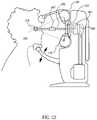
- FIG. 1Aillustrates a side view of embodiments of a system for treating the eye using radiotherapy.
- FIG. 1Bis a schematic format of embodiments of a radiotherapy treatment system.
- FIG. 1Cis a schematic of the eye.
- FIGS. 1D and 1Edepict embodiments of a radiotherapy system which communicates with a lens on the eye.
- FIG. 1Fdepicts an x-ray radiation spectrum.
- FIG. 2Aillustrates a side schematic view of embodiments of a radiotherapy system illustrating some system components of FIGS. 1A-B .
- FIGS. 2 B′- 2 B′′′′illustrate several embodiments of various collimators.
- FIG. 2Cillustrates embodiments of a radiotherapy system targeting a location within an eye for treatment.
- FIG. 2Dillustrates some embodiments of a radiotherapy system targeting a location within an eye for treatment.
- FIG. 2Eillustrates a schematic view of a radiotherapy system and a method of clinical application of the system.
- FIG. 3depicts embodiments of a subsystem of a radiotherapy control module.
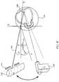
- FIG. 4illustrates a side view of an eye wherein eye location is tracked according to certain methods.
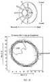
- FIG. 5illustrates a representative geometric model of the eye used for modeling purposes.
- FIG. 6illustrates representative beam angles with respect to an anterior surface and geometric axis of the eye.
- FIGS. 7A-7Fillustrates representative simulations of radiation beams traveling through an eye to reach a retina of the eye and a dose profile for a target tissue.
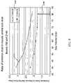
- FIG. 8depicts the results of Monte Carlo simulation performed to analyze the effect of different energies and doses on the structures of an eye.
- FIG. 9depicts the results of Monte Carlo simulation performed to analyze the effect of various treatment regimes on the various structures of the eye.
- FIG. 10depicts experimental results of thin x-ray beams traveling through a human eye to validate a Monte Carlo simulation model.
- FIGS. 11A 1 - 11 Bdepict the results of thin x-ray beams penetrating through an ophthalmic phantom to investigate penumbra and dosage variables.
- the present embodimentsinclude systems and methods for treating a human eye with radiotherapy. Some embodiments described below relate to systems and methods for treating macular degeneration of the eye using radiotherapy. For example, in some embodiments, systems and methods are described for use of radiotherapy on select portions of the retina to impede or reduce neovascularization of the retina. Some embodiments described herein also relate to systems and methods for treatment of glaucoma or control wound healing using radiotherapy. For example, in some embodiments, systems and methods are described for use of radiotherapy on tissue in the anterior chamber following glaucoma surgery, such as trabeculoplasty, trabeculotomy, canaloplasty, and laser iridotomy, to reduce the likelihood of postoperative complications.
- glaucoma surgerysuch as trabeculoplasty, trabeculotomy, canaloplasty, and laser iridotomy
- systems and methodsare described to use radiotherapy to treat drusen, inflammatory deposits in the retina that are thought to lead to vision loss in macular degeneration. Localization of a therapy to the drusen to treat the surrounding inflammation may prevent the progression of dry and/or wet AMD.
- a laser therapeuticis applied to the drusen in combination (adjuvant therapy) with co-localized x-ray radiation to substantially the same spot where the laser touched down on the retina; the laser spot can create a localized heating effect which can facilitate radiation treatment or the laser spot can ablate the region and the radiation can prevent further scarring around the laser spot.
- adjuvant therapiescan include x-ray radiotherapy in combination with one or more pharmaceuticals or other radiotherapy enhancing drugs or chemical entities.
- Radiationcan have both a broad meaning and a narrow meaning in this disclosure. Radiation, as used herein, is intended to have its ordinary meaning and is meant to include, without limitation, at least any photonic-based electromagnetic radiation which covers the range from gamma radiation to radiowaves and includes x-ray, ultraviolet, visible, infrared, microwave, and radiowave energies. Therefore, planned and directed radiotherapy can be applied to an eye with energies in any of these wavelength ranges.
- Radiotherapycan refer to treatment of disease using x-ray radiation; however, in this disclosure, radiotherapy is intended to have its ordinary meaning and is meant to include, without limitation, at least any type of electromagnetic radiation which uses photons to deliver an energy as a clinical therapy to treat a disease.
- X-ray radiationgenerally refers to photons with wavelengths below about 10 nm down to about 0.01 nm.
- Gamma raysrefer to electromagnetic waves with wavelengths below about 0.01 nm.
- Ultraviolet radiationrefers to photons with wavelengths from about 10 nm to about 400 nm.
- Visible radiationrefers to photons with wavelengths from about 400 nm to about 700 nm. Photons with wavelengths above 700 nm are generally in the infrared radiation regions.
- orthovoltageWithin the x-ray regime of electromagnetic radiation, low energy x-rays can be referred to as orthovoltage. While the exact photon energies of orthovoltage varies, for the disclosure herein, orthovoltage refers at least to x-ray photons with energies from about 20 KeV to about 500 MeV.
- the global coordinate systemrefers to a physical world of a machine or room.
- the global coordinate systemis preferably a system relating a machine, such as a computer or other operating device, to the physical world or room that is used by the machine.
- the global coordinate systemcan be used, for example, to move a machine, components of a machine, or other things from a first position to a second position.
- the global coordinate systemcan also be used, for example, to identify the location of a first item with respect to a second item.
- the global coordinate systemis based on a one-dimensional environment.
- the global coordinate systemis based on a two-dimensional environment, and in some embodiments, the global coordinate system is based on three or more dimensional environments.
- Kermarefers to the energy released (or absorbed) per volume of air when the air is hit with an x-ray beam.
- the unit of measure for Kermais Gy.
- Air-kerma rateis the Kerma (in Gy) absorbed in air per unit time.
- tissue kermarate is the radiation absorbed in tissue per unit time. Kerma is generally agnostic to the wavelength of radiation, as it incorporates all wavelengths into its joules reading.
- the beam shapeis generally set by the last collimator opening in the x-ray path; with two collimators in the beam path, the secondary collimator is the last collimator in the beam path and can be called the “shaping collimator.”
- the first collimatormay be called the primary collimator because it is the first decrement in x-ray power and generally is the largest decrement of the collimators; the second collimator can generally set the final shape of the x-ray beam.
- the last collimator openingis a square
- the beam shapeis a square as well.
- the last collimator openingis circular
- the penumbrarefers to the fall-off in dose outside of the area of the last collimator and b earn shape and size set by that collimator, typically measured at some distance from the last collimator.
- Penumbraas used herein, has its ordinary meaning, which is meant to include, without limitation, the percentage of radiation outside the area of the last collimator when the x-ray beam reaches the surface of the eye or the target within the eye, whichever structure is the one being referenced with respect to the penumbra.
- the penumbracan incorporate the divergence of the beam as well as the scatter of the beam as it travels through the air and through the tissue.
- the size of the primary beamis the same size as the last collimator to which the x-ray beam is exposed; that is, the penumbra is ideally zero.
- the penumbracan be optimized, for example, by the shape of the collimator, the material of the collimator, the processing of the collimator material, the position of the anode of the x-ray tube, and the relative sizing of the collimator relative to the x-ray source.
- the penumbra area percentage at the entry point to the eyeis less than about 10%. In some embodiments, the penumbra area percentage at the entry point to the eye is less than about 5%, and in some embodiments, the penumbra area percentage is less than about 1%.
- the penumbracan also refer to the percentage of radiation outside the zone of the shaping collimator at a target region of the macula.
- the penumbra at the maculais less than about 40% and in some embodiments, the penumbra at the macula is less than about 20%, and in some embodiments, the penumbra at the macula is less than about 10% or less than about 5%.
- the penumbracan be incorporated into a treatment plan; for example, predictive knowledge of the penumbra can be utilized to plan the treatment.
- a finely collimated beam(e.g., having a 4 mm diameter) is applied to the sclera.
- the beam at the retinacan be 5 mm (25% penumbra) or 6 mm (50% penumbra) diameter sufficient for coverage of a lesion.
- isodose fall-offrefers to the dose fall-off independent of divergence angle of the beam.
- isodose fall offis the same as penumbra.
- the isodose fall-offis different from the penumbra, referring to the fall-off of dose around the shaping collimator beam without accounting for divergence angle.
- the isodose fall offis measured in Gy/mm, a linear distance from the edge of the collimator shape over a distance.
- Divergence anglestypically follow a 1/R 2 relationship assuming the source is a point source or close to a point source. Divergence angle is highly predictable for photons and can be calculated independently of scatter and the other physics which go into Monte Carlo simulations.
- Photons with shorter wavelengthscorrespond to radiation with higher energies.
- the higher-energy range of x-raysis generally in the MeV range and is generally referred to gamma x-rays, independent of how the radiation was generated.
- X-ray photons with relatively shorter wavelengthsare referred to as orthovoltage x-rays.
- Higher energy radiation with shorter wavelengthscorresponds to deeper penetration into target tissue, which is the reason that most applications using MeV energies require extensive shielding of the patient and surroundings.
- x-rays typically used for diagnostic purposes, or low energy orthovoltage x-ray sourcescan be used for therapy of ocular diseases and/or disorders which are relatively superficial in the patient such as breast, intra-operative radiation application, skin cancers, and other disorders such as peripheral vascular disease, implants, etc.
- X-rays typically used for diagnosiscan be used for therapy by tightly collimating the x-ray beam into a thin beam of x-ray photons and directing the beam to the superficial region to be treated. If the disorder is deeper than several centimeters inside the body, then higher energy sources (e.g., MeV) may be preferred to enhance penetration of energy to the disorders.
- MeVhigher energy sources
- MeV x-ray beamsIt is difficult to collimate MeV x-ray beams to small diameters with small penumbras because their very high speed photons cause secondary interactions with tissue including generation of secondary x-rays and other radiations.
- X-rays with energies lower than 500 KeV and even lower than 200 KeVcan more appropriately be collimated to very small diameters.
- Laser energyis also composed of photons of different energies ranging from short wavelengths, such as ultraviolet radiation, up to long wavelengths, such as infrared radiation. Laser refers more to the delivery mechanism than to the specific wavelength of radiation. Laser light is considered “coherent” in that the photons travel in phase with one another and with little divergence. Laser light is also collimated in that it travels with relatively little divergence as is proceeds in space (penumbra). Light can be collimated without being coherent (in phase) and without being a laser; for example, lenses can be used to collimate non-x-ray light. X-ray light is typically collimated with the use of non-lens collimators, the penumbra defining the degree of successful collimation.
- Laser pointersare typically visualization tools, whereas larger, higher-flux lasers are utilized for therapeutic applications.
- opticscan be used, such as lenses or mirrors, and in some embodiments, there are no intervening optical elements, although collimators may be used.
- the two eye chambersare the anterior and posterior chambers.
- the anterior chamberincludes the lens, the conjunctiva, the cornea, the sclera, the trabecular apparatus, the ciliary bodies, muscles, and processes, the iris, etc.
- the posterior chamberincludes the vitreous humor, the retina, and the optic nerve.
- Opticular diseasesis intended to have its ordinary meaning, and is meant to include at least disease of the anterior eye (e.g., glaucoma, presbyopia, cataracts, dry eye, conjunctivitis) as well as disease of the posterior eye (e.g., retinopathies, age related macular degeneration, diabetic macular degeneration, and choroidal melanoma).
- anterior eyee.g., glaucoma, presbyopia, cataracts, dry eye, conjunctivitis
- retinopathiese.g., age related macular degeneration, diabetic macular degeneration, and choroidal melanoma
- Drusenare hyaline deposits in Bruch's membrane beneath the retina.
- the depositsare caused by, or are at least markers of inflammatory processes. They are present in a large percentage of patients over the age of 70. Although causality is not known, drusen are associated with markers of the location where inflammation is occurring and where neovascularization has a high likelihood of occurring in the future; these are regions of so called “vulnerable retina.” Therefore, applying inflammation reducing radiation to the region may be beneficial to the patient.
- Brachytherapy described aboveappears to have a highly beneficial effect at least when combined with pharmaceutical therapy as an adjuvant therapy.
- Brachytherapydefinitively localizes the radiation dose to the region to be treated and ensures that the dose is delivered at a high rate.
- brachytherapyis difficult to control as far as a treatment plan (e.g., the surgeon can hold the probe in a variety of positions for any given patient) and the brachytherapy source typically cannot be turned off (e.g., strontium has a 29 year half-life).
- the Portable Orthovoltage Radiotherapy Treatment system (PORT) 10 in FIG. 1Acan be configured to deliver anywhere from about 1 Gy to about 40 Gy or from about 10 Gy to about 20 Gy to regions of the eye including the retina, sclera, macula, optic nerve, the capsular bag of the crystalline or artificial lens, ciliary muscles, lens, cornea, canal of schlemm, choroid, conjunctiva, etc.
- the systemcan be configured to deliver from about 15 Gy to about 25 Gy.
- the system 10is capable of delivering x-ray therapy in any fractionation scheme (e.g. 5 Gy per day or 10 Gy per month or 25 Gy per year) as the treatment planning system can recall which regions had been treated based on the unique patient anatomical and disease features. These features and previous treatments are stored in the treatment database for future reference.
- the systemcan also deliver different photon energies depending on the degree of disease or the region of the eye being treated.
- the x-ray generation tubecan deliver from about 20 KeV photons to about 40 KeV photons or to about 60 KeV photons, or to about 100 KeV photons. It may be desirable to use about 20 KeV to about 50 KeV photons for structures in the anterior portion of the eye because these energies will penetrate less whereas it may be desirable to utilize from about 60 KeV to about 100 KeV photons or greater for structures in the posterior region of the eye for greater penetration to the retina.
- the x-ray generation tubecan deliver photons with photon energies from about 10 keV to about 500 keV, from about 25 keV to about 100 keV, from about 25 keV to about 150 keV, and/or from about 40 keV to about 100 keV.
- selection of the photon energycan be based on diagnostic calculations, which can include a model of the eye created from anatomic data taken from the actual eye.
- PORTcan be applied to any superficial body structure within reach of orthovoltage x-rays or to structures accessible during surgical procedures. For example, in regions such as the breast, it may be desirable to use x-rays with energies greater than about 40 keV but less than about 200 keV to reach the structures of interest.
- Other structures of interestinclude, for example, skin lesions, facial lesions, mucosal lesions of the head and neck, nails, muscles, soft tissues, anorectal regions, prostate, genital regions, joints, tendons, muscles, and the urogenital tract.
- PORTcan be applied to specific structures within the eye while sparing others because of its imaging systems, its modeling systems, and its finely-tunable collimators can provide precisely directed x-ray beams that can be targeted on specific structures within the eye with small penumbras (for example, 1-5 mm beams with less than 10% penumbra).
- PORT therapyis also based on individualized, biometric representations of the eye which allows a personalized treatment plan to be created for every patient.
- orthovoltage generatorsor other low energy x-ray generators, allow for the system to be placed in a room without requiring thick protective walls or other special shielding apparatus or special controls which would be prudent with devices generating x-rays with photon energies greater than about 500 keV.
- Orthovoltage generators, or other low energy x-ray generatorsare also more compact than linear accelerators which allow them to be moved and directed with less energy from control motors as well as with less internal and external shielding.
- the lower energy x-ray generatorsalso allow for simpler collimation and beam directing schemes with small penumbras and tight collimation.
- much less energyis used to move the source to different positions, and the entire system is scaled down in size with lower energy x-ray sources.
- the radiotherapy systemis used to treat a wide variety of medical conditions relating to the eye.
- the systemmay be used alone or in combination with other treatments to treat macular degeneration, diabetic retinopathy, inflammatory retinopathies, infectious retinopathies, tumors in the eye or around the eye, glaucoma, refractive disorders, cataracts, post-surgical inflammation of any of the structures of the eye (e.g., trabeculoplasty, trabeculectomy, intraocular lenses, glaucoma drainage tubes, corneal transplants, infections, idiopathic inflammatory disorders, etc.), ptyrigium, dry eye, and other ocular diseases or other medical conditions relating to the eye.
- the radiotherapy treatment systempreferably includes a source, a system to control and move the source, an imaging system, and an interface for a health care professional to input treatment parameters.
- some embodiments of the radiotherapy systeminclude a radiotherapy generation module or subsystem that includes the radiation source and the power supplies to operate the source, an electromotive control module or subsystem which operates to control the power to the source as well as the directionality of the source, a coupling module which links the source and control to the structures of interest (e.g., the eye), and an imaging subsystem; these modules are linked to an interface for a healthcare professional and form the underpinnings of the treatment planning system.
- the terms “module” and “subsystems”can be used interchangeably in this disclosure.
- FIG. 1Aillustrates a side view of embodiments of a system 10 for treating ocular diseases using radiotherapy.
- the radiotherapy treatment system 10comprises a radiotherapy generation module or subsystem 110 , a radiotherapy control module or subsystem 120 , an interface display 130 , a processing module 140 , a power supply 150 , a head restraint 160 , and an imaging module with a camera 400 .
- the radiotherapy devicedelivers x-rays to the eye 210 of a patient 220 .
- the power supply 150preferably resides inside the system 10 or adjacent the system 10 (e.g., on the floor). In some embodiments, however, the power supply 150 can reside in a different location positioned away from the system 10 .
- the power supply 150can be physically coupled to the x-ray generator 110 (in a monoblock configuration) or can be uncoupled from the x-ray generator (e.g., the x-ray source moves independently of the power supply and is connected through high power cables).
- a cooling system for the X-ray tubeis also provided.
- the cooling systemcan be water or oil or air convection and can be attached or located a distance from the radiotherapy system 10 .
- Voltagecan be wall voltage of about 110V or 220V (with assistance of a transformer) which can be used for the devices in the system shown in FIG. 1A .
- Currents to drive x-rays out of the devicemay be on the order of 1 amp or lower down to about 50 mA or even about 5-10 mA.
- What is desired of the power supplyis that a high voltage be generated to drive the electrons from the cathode in the x-ray tube to the anode of the x-ray; electron movement is performed within a vacuum inside the x-ray tube.
- the high voltage(e.g., about 30,000-300,000 volts or higher) may be desired to accelerate the electrons inside the vacuum.
- a second currentis typically used with x-ray power supplies in order to generate the electrons from a filament, the electrons are subsequently accelerated through the voltage potential. Therefore, x-ray power supplies typically have two power supplies in order to generate x-rays. Once generated, the electrons speed toward the anode under the influence of the high voltage potential; the anode is where the x-ray generating material typically rests (e.g., tungsten, molybdenum).
- x-raysare generated.
- An absorbing metale.g., aluminum, lead, or tungsten
- the x-rays, which are pre-planned to escape,are emitted from the source and travel into a collimator (e.g., a primary or secondary collimator) and optionally through a filter (e.g. an aluminum filter).
- the collimatoris intended to direct the x-rays toward the patient 220 .
- collimatorscan be designed and manufactured so as to minimize penumbra formation and scatter and to optimize the shape and/or direction of the x-ray beam.
- the power supplyis preferably connected to the x-ray source by a high power cable that is highly insulated to prevent power leakage.
- the collimatorcan be one or more collimators (e.g., a primary 1030 and a secondary collimator 1040 , and even a third collimator 1052 , as illustrated in FIG. 2A ).
- a secondary (shaping) collimatoris placed close to the eye 1300 (e.g., within 10 cm) of the patient, and the primary collimator 1030 is placed close to the source 1070 . This type of configuration can decrease the penumbra generated by the source 1070 on the ocular structures 1300 .
- collimatorsare specialized apertures.
- the aperturescan be adjustable; for example, the aperture can be adjustable from about 1.0 cm to about 0.5 mm or below 0.5 cm to about 0.01 cm.
- the apertureis adjustable (e.g., automatically or manually by the operator of the machine) between about 0.5 mm and about 7.0 mm.
- the collimatoris constructed from tungsten, lead, aluminum, or another heavy metal.
- the collimatorhas a cylindrical shape for the radiation to pass through; in other embodiments, the collimator has a coned shape for the radiation to pass through.
- the collimator aperturehas a rounded shape.
- the collimatorhas a curvilinear shape for the x-ray to pass through.
- the collimatoris cut using wire-EDM; in other embodiments, the collimator path is cut and polished using a laser.
- the smooth contour of the collimatorallows for minimal scattering as the radiation passes through the collimation apparatus.
- the collimatorhas a region of thinner metal than another region so that the beam is relatively modified but does not have a sharp contour.
- a light pointer 1410(e.g., a laser beam emitted from a source 1450 ) is coupled to a collimator 1405 , or behind the collimator 1405 , so that the light pointer 1410 is coincident with an x-ray beam 1400 ; the light pointer 1410 can indicate the position on a surface of an eye 1300 through which the radiation source enters by tracking angles of incidence 1420 , 1430 of the collimator and x-ray beam.
- the collimator 1405is preferably co-linear with the light source 1450 which can act as a pointer to indicate the point on the eye through which the radiation enters the eye 1300 .
- a laser pointer 1210sits on top of, or is coincident with the x-ray beam through the primary or secondary collimator 1215 .
- the laser pointer 1210can be reflected off a reflector 1220 that aligns the laser pointer 1210 with the collimator opening 1216 such that the laser point 1210 strikes substantially the same position of a surface beyond the collimator opening as does the x-ray 1200 .
- the reflector 1220can be a beam splitter, and the beam splitter can be transparent to x-ray energy 1200 .
- the laser pointer 1210can emit a wavelength that is detectable by the system camera 1460 .
- the pointer 1410can also serve as a visual verification that the x-ray source is powered on and directed in the proper orientation with respect to the ocular structure, or target tissue 1480 , of interest. With a second camera in the system, the angle of incidence of the laser pointer and the x-ray beam can be determined.
- At least one camera 400 , 1460is included in the system to at least track the eye in real time.
- the camera 400 , 1460images the eye with or without the x-ray source tracking device (e.g., laser pointer) described above.
- the cameracan detect the position of the eye and relate the direction of the x-ray and collimator system to the position of the eye.
- An optional display 130 directed to the operator of the radiotherapy system on the system 10can depict the position of the x-ray device in real time in some embodiments.
- the camera 2055detects the position of the eye and digitizing software is used to track the position of the eye.
- the eyeis meant to remain within a preset position 2060 ; when the eye deviates from the position 2060 beyond a movement threshold, a signal 2090 can be sent to the radiation source 2000 .
- the term “movement threshold”is intended to have its ordinary meaning, which includes, without limitation, a degree or measurement that the eye is able to move and still be within the parameters of treatment without shutting the radiation source 2000 off.
- the movement thresholdcan be measured in radians, degrees, millimeters, inches, etc.
- the radiation source 2000is turned off when the eye is out of position 2057 beyond the movement threshold, and the radiation source is turned on when the eye is in position 2054 , or within the movement threshold.
- a connection, or coupling, 162extends from the system and contacts the eye 210 ( FIGS. 1D-1E ).
- the connectioncan be a physical connection which can include an optical or other communication between the system and the eye in addition to a mechanical connection.
- the physical connection 162can serve several functions.
- the connection 162is a mechanical extension which allows the position of the eye to be determined because it is directly applied to the cornea or sclera. It also provides for inhibition of the eye so that the patient is more inclined to be compliant with keeping their eye in one position throughout the treatment.
- the eyecan be moved into a pre-determined position, in the case, for example, when the patient's eye has been paralyzed to perform the procedure.
- the physical contact with the eyecan be used to protect the corneal region using an ophthalmic lubricant underneath the physical contact device.
- the physical connection 162 from the corneaallows for positioning of the eye with respect to the system.
- the physical connection 162 to the eye from the radiotherapy system 10can contact the limbus 910 (also see FIG. 1C 308 ) around the eye or can contact the cornea 920 or the sclera 930 .
- the physical connectioncan contain a suction type device 912 which applies some friction to the eye in order to move the eye or hold the eye in place with some force.
- the connection 162contacts the sclera when suction is applied.
- the physical connection 162can dock onto a scleral lens 940 or a corneal lens which is inserted separately into the eye; piece 160 then docks into the scleral contact lens. Any of the materials of the physical connection can be transparent to x-rays or can absorb some degree of x-ray.
- the physical connection 162can help to stabilize the eye of the patient, preventing eye movement underneath the lens. If a lubricant is inserted inside the lens, the lens can hold a gel or lubricant to protect the eye during the procedure.
- the lenscan also contain through holes which can provide the cornea with oxygen.
- the physical connection 162can be movable with respect to the remainder of the radiotherapy system; the physical connection 162 can be rigid, substantially rigid, or can contain a spring 165 , which allows flexibility in the axial or torsional direction. In some embodiments, the connection 162 is not mechanical at all but is an optical or other non-contact method of communicating between a radiotherapy system and a lens 940 positioned on the eye.
- the physical connection 162can signify the coordinate reference frame for the radiotherapy system and/or can signal the movement of the device with respect to the eye. Connection 162 can therefore assist in maintaining eye location in addition to maintaining eye position by inhibiting movement of the patient.
- Physical connection 162can contain radiotranmitters or features which can be captured on a camera so that the eye can be located in three-dimensional space.
- the physical connection 162 to the eyeis docked into position on the eye by the physician so that it identifies the center of the limbus and the treatment axis through its center.
- the position of the eyecan then be identified and tracked using by the radiotherapy system.
- the radiotherapy systemcan then be directed about the treatment axis and center of the limbus to deliver radiation to the retina.
- X-ray source 110can travel around a central axis 405 or a focal point within the eye 210 , such as, for example, illustrated in FIG. 1D by arrows 112 .
- the x-ray source 110can travel around a floating focal point as defined by the treatment planning system and virtual model of the eye.
- a floating focal pointis one anywhere in the eye as opposed to a fixed focal point such as the macula for example.
- the x-ray sourcecan move with six degrees of freedom around a fixed or moving axis.
- the x-ray sourceremains fixed in one spot to treat an eye structure in the anterior portion of the eye or even the posterior portion of the eye depending on how large an area is to be treated and the dose required.
- the x-ray source 110focuses x-rays on a target by moving to different positions around the eye and delivering x-rays through the sclera at substantially different entry points on the sclera but each x-ray beam reaching a substantially similar target within the eye.
- the x-ray sourceremains in one location, delivering x-ray energy to and through the sclera and to regions within the eye, such as the retina and specifically the macula.
- the x-ray source 110is moved with five degrees of freedom, four degrees of freedom, three degrees of freedom, or two degrees of freedom.
- the x-ray source 110is stationary and the collimator is moved or the eye or the patient is moved to project the beam to different regions of the eye.
- the retinais treated by maintaining the x-ray beam in one position with respect to the sclera.
- the x-ray source 110can be moved automatically by a robotic arm or manually by the operator of the system.
- the ultimate three-dimensional position of the x-ray source 110can be dictated by the treatment plan which communicates between a model of the eye and with the robotic arm to determine the position of the x-ray beam relative to the eye.
- only a small amount of movementis required of the x-ray source to entirely treat a disease of the retina, such as macular degeneration and/or diabetic macular edema.
- six degrees of freedomcan be applied to the x-ray source 110 , but the range of each degree of freedom is preferably limited so that the movement system only travels within a volume of about 1000 cm 3 , 500 cm 3 , 100 cm 3 , or about 50 cm 3 .
- the speed of the robot within these volumescan be defined such that the robot moves 0.5 cm/s, 1 cm/s, 3 cm/s, 5 cm/s. Because each fractional treatment dose is relatively short and applied over a small distance, the robot can sacrifice speed and travel distance for smaller size.
- Pars plana 215is the region of the eye between the pars plicata 218 and a peripheral portion of the retina 280 , the ora serrata.
- the pars plana 215 region of the eyecontains the fewest critical structures enroute from the sclera 260 to the retina 280 . It is typically the region through which surgeons will inject pharmaceuticals in order to inject drugs into the eye or to perform vitrectomies because the smallest risk of damage to ocular structures exists with this approach.
- radiotherapycan be delivered to the posterior region of the eye through the pars plana region 215 to minimize the potential for damage to structures such as the lens, yet reaching regions such as the fovea 240 and with minimal radiation reaching the optic nerve 275 .
- the image-guided orthovoltage therapy described hereinallows such specific treatment.
- the central axis 300 of the eyeis typically defined by the geometric axis 300 , but in some embodiments, it can be defined by the visual axis 305 ; the visual axis of the eye is represented by a line 306 from the center of the fovea 305 through the center of the pupil.
- the geometric axis 300can be defined by a perpendicular straight line 300 from the center of the limbus 308 straight directly back to the retina; this axis can also be referred to as the treatment axis.
- the limbus 308is technically the point where the cornea meets the sclera or visually the point where the pigmented region of the eye meets the white region of the eye.
- the pars plana angle 212can be measured from the geometric central axis 300 and can range from about 10 degrees to about 50 degrees off the central geometric axis 300 .
- the visual axis 306is the straight line from the center of the macula 240 and out the front of the eye through the center of the pupil 217 .
- the pars plana 215 region of the eyecan be related to the central axis 300 of the eye through an angle ⁇ 212 .
- x-rays with a tight collimatione.g., smaller than about 6-8 mm in diameter
- a small penumbrae.g., less than about ten percent at the sclera
- the eyecan be stabilized with the assistance of physical or mechanical restraint or by patient fixation on a point so that the x-rays enter the eye substantially only in the pars plana region 215 .
- the patientis stabilized with respect to the axis of the eye. If the patient or device moves, then the camera detects the movement and turns the device off or closes a shutter over the region the x-rays leave the device or the collimator.
- the x-ray source 110is moved about the eye to one or more positions determined by a treatment planning system, delivering radiation through the pars plana region 215 of the eye to reach the retina. The total dose is divided across different regions of the sclera but penetrates through the pars plana 215 region to reach the desired region of the retina (for example, the macula or the fovea).
- the head restraint 160 portion of the radiotherapy system 10may be used for restraining the head of the patient 220 so as to substantially stabilize the location of the patient's eye 210 relative to the radiotherapy treatment system 10 .
- the physician applying the treatmentcan align the central axis 300 of the patient's eye with the x-ray source.
- the restraint 160can maintain the patient's position during the treatment. If the patient moves away from the restraint 160 or moves their eyes from the restraint, then the x-ray machine can be turned off (gating) manually or automatically and the patient's position readjusted.
- the patient's headis maintained in position with the head restraint 160 while the eye 210 is tracked by the imaging system 400 and/or treatment planning system and the x-ray source 110 is moved so that the x-ray beam enters the eye through the pars plana region 215 ; the x-rays, therefore, penetrate to the target regions of the retina and create minimal damage on their way to the retina.
- the treatment planning system 800( FIGS. 1B and 2E ) provides the physician interface with the system 10 .
- the treatment planis developed based on pre-treatment planning using a combination of biometric modalities including an imaging subsystem that can include, for example, OCT, or optical coherence tomography, CT scans, MRI scans, and/or ultrasound modalities.
- the information from these modalitiesare integrated into a computer-generated virtual model of the eye which includes the patient's individual anatomic parameters (biometry) as well as the individual's specific disease burden.
- the treatment planis output, for example, on the interface display 130 module of the radiotherapy system 10 .
- the physiciancan then use the virtual model in the treatment plan to direct the radiation therapy to the disease using the radiotherapy system 10 .
- eye modelor “model of the eye” refers to any representation of an eye based on data, such as, without limitation, an anteroposterior dimension, a lateral dimension, a translimbal distance, the limbal-limbal distance, the distance from the cornea to the lens, the distance from the cornea to the retina, a viscosity of certain eye structures, a thickness of a sclera, a thickness of a cornea, a thickness of a lens, the position of the optic nerve relative to the treatment axis, the visual axis, the macula, the fovea, a neovascular membrane, and/or an optic nerve dimension.
- an anteroposterior dimensionsuch as, without limitation, an anteroposterior dimension, a lateral dimension, a translimbal distance, the limbal-limbal distance, the distance from the cornea to the lens, the distance from the cornea to the retina, a viscosity of certain eye structures, a thickness of a sclera, a thickness of
- Such datacan be acquired through, for example, imaging techniques, such as ultrasound, scanning laser opthalmoscopy, optical coherence tomography, other optical imaging, imaging with a phosphor, imaging in combination with a laser pointer for scale, and/or T 2 , T 1 , or functional magnetic resonance imaging.
- imaging techniquessuch as ultrasound, scanning laser opthalmoscopy, optical coherence tomography, other optical imaging, imaging with a phosphor, imaging in combination with a laser pointer for scale, and/or T 2 , T 1 , or functional magnetic resonance imaging.
- imaging techniquessuch as ultrasound, scanning laser opthalmoscopy, optical coherence tomography, other optical imaging, imaging with a phosphor, imaging in combination with a laser pointer for scale, and/or T 2 , T 1 , or functional magnetic resonance imaging.
- Such datacan also be acquired through keratometry, refractive measurements, retinal nerve-fiber layer measurements, corneal topography, etc.
- the data used to produce an eye modelmay be processed and/or displayed using
- FIG. 1Bdepicts a schematic overview of the x-ray treatment system 10 .
- the overall treatment planning system 800is depicted by the background oval shape, depicting a global interconnect between the subsystems.
- the treatment planning system 800directs the four subsystems toward treatment of the region indicated by the physician.
- the four subsystemsin general terms include an x-ray subsystem 700 , a coupling subsystem 500 , an electromotive subsystem 600 , and an imaging subsystem 400 . These subsystems or modules interact to provide an integrated treatment to the eye of a patient.
- the subsystemswork together to coordinate the treatment planning system 800 .
- the treatment planning system (TPS) 800also provides the interface between the physical world of the eye, the physical components of the system, and a virtual computer environment which interacts with the physician and treatment team and contains the specific patient and disease information.
- the coupling system 500primarily, and the imaging system 400 , secondarily, help link the physical world and the virtual world.
- the virtual worldcontains a computer-generated virtual model of the patient's eye 505 based on physical and biometric measurements taken by a health practitioner or the imaging system 400 itself.
- the computer model 505 ( FIG. 2D ) in the virtual worldfurther has the ability to simulate the projection 510 of an x-ray beam 520 from a radiation source 524 through an anterior region of the eye 515 to the structure 514 to be treated on or in the eye 514 based on different angles of entry into the eye.
- the modelcan also include important eye structures, such as the optic nerve 512 , to consider during the treatment planning process.
- the virtual worldalso contains the physician interface to control the device 524 and interface the device with respect to the physical world, or that of the actual physically targeted structure.
- the coupling subsystem 500(in the physical world) can include a mechanism to determine the angle of incidence of the x-ray beam with respect to the surface of the eye using one or more laser or angle detectors, as discussed above.
- the coupling system 500contains a camera 518 which can image a spot 516 on or in an eye. Information from the camera is then preferably transferred to the virtual eye model 522 and again to the motion and radiotherapy system 524 .
- the coupling system 500is a physical connection with the eye.
- the coupling system 500is not a physical link but is a communication link between a lens on the eye and a detection system.
- a lenscan be a communication beacon to relay eye position to the system 500 .
- the lenscan contain markers that are imaged by the imaging camera 518 , through which the next stage in the therapy can be determined. In some embodiments, a combination of these techniques is used.
- the position of the eye and the x-ray sourceare known at all times, and the angles of entry of the x-ray can therefore be realized.
- the central axis of the eyecan be determined and the x-ray source offset a known angle from the central axis.
- the central axis, or treatment axisin some embodiments can be assumed to be the axis which is perpendicular to the center of the cornea or limbus and extends directly posterior to the retina, as discussed previously.
- the coupling subsystemcan detect the “glint” or reflection from the cornea. The relationship between the glint and the center of the pupil is constant if the patient or the patient's eye is not moving.
- a detectorcan detect when this occurs, and a signal can be sent from the virtual world to the x-ray device to turn the x-ray device off or to shutter the system off.
- the information obtained from the coupling subsystemis preferably sent to the computer system and to the virtual eye model.
- the imaging subsystem 400captures an image of the eye in real time with a camera 1460 and feeds the data into the software program that creates a virtual model of the eye.
- the predicted path of the x-ray beam through the eyecan be created on the virtual image.
- the electromotive system and/or x-ray systemcan be readjusted; for example, a robot arm can move the x-ray source 110 to a position to send a radiation or x-ray beam to a location on or in the eye based on the model of the eye as created by the TPS and as captured by the imaging system 400 .
- the radiotherapy generation system 100can include an orthovoltage (or low energy) radiotherapy generator as the x-ray subsystem 700 , as discussed in further detail with reference to FIG. 1A , a schematic of the device.
- the radiotherapy generation subsystem 110generates radiotherapy beams that are directed toward the eye 210 of the patient 220 in FIG. 1A .
- the radiotherapy control module 120includes an emitter 200 that emits a directed, narrow radiotherapy beam generated by the radiotherapy generation subsystem 110 .
- the term “emitter”is intended to have its plain and ordinary meaning, and the emitter can include various structures, which can include, without limitation, a collimator.
- the control module 120is configured to collimate the x-ray beams as they are emitted from the radiotherapy generation subsystem 110 .
- the x-ray subsystem 700can direct and/or filter radiotherapy rays emitted by the x-ray tube so that only those x-rays above a specific energy pass through the filter.
- the x-ray subsystem 700can include a collimator through which the pattern or shape of an x-ray beam is determined.
- the filtering of the sourcepreferably determines the amount of low energy inside the x-ray beams as well as the surface-depth dose as described in ensuing figures.
- the radiotherapy control systemcan control one or more of the power output of the x-ray, the spectrum of the x-ray, the size of the beam of the x-ray, and the penumbra of the x-ray beam.
- the electromotive subsystem 600 of the radiotherapy systemmay move the x-ray source and the collimator to direct a narrow radiotherapy beam emitted from the x-ray source to irradiate specific regions of the patient's eye 210 by directing energy onto or into targeted portions of the eye 210 , while at the same time avoiding irradiation of other portions of the eye 210 .
- the system 10may target a structure of the posterior region of the eye, such as the retina, or a structure on the anterior region of the eye, such as the trabecular meshwork, the sclera, the cornea, the ciliary processes, the lens, the lens capsule, or the canal of schlemm.
- the system 10can deliver radiotherapy to any region of the eye, including, but not limited to, the retina, the sclera, the macula, the optic nerve, the ciliary bodies, the lens, the cornea, Schlemm's canal, the choroids, the capsular bag of the lens, and the conjunctiva.
- the x-ray subsystem 700can collimate the x-ray to produce a narrow beam of specified diameter and shape.
- the diameter of the collimator outletmay be increased or decreased to adjust the diameter of the radiotherapy beam emitted by the collimator.
- the x-ray subsystem 700can emit a beam with a diameter of about 0.1 mm to about 6 mm.
- the x-ray subsystem 700can emit a beam with a diameter of less than about 0.1 mm.
- the x-ray subsystem 700can emit a beam with a diameter of between about 0.5 mm and about 5 mm.
- the radiation control modulecan emit an x-ray beam with a circular 1212 or non-circular 1214 shape; in some embodiments, the radiation control module can emit an x-ray beam with a rectangular shape 1214 or a square shape. In some embodiments, the radiation control module can emit an x-ray beam with an arc shape or an elliptical shape or a doughnut configuration 1217 through a circular collimator 1215 with an opaque region 1218 in the center. In some embodiment, the collimator 1215 can include a conical-shaped opening 1232 , such as depicted in FIG. 2 B′′′′, for providing a precisely shaped beam 1200 .
- the radiotherapy system 10allows for selective irradiation of certain regions of the eye without subjecting other areas of the eye to radiation by using a narrow, directed treatment beam, the treatment beam dictated by the specific anatomy of the patient's eye.
- the radiotherapy control module 120can direct radiotherapy beams generated by the radiotherapy generation module 110 to a patient's macula, while substantially avoiding radiation exposure to other portions of the patient's eye, such as the lens, the trabecular apparatus, and the optic nerve.
- the x-ray beamfollows a trajectory 250 that enters the eye through the pars plana region 215 which is a zone of the sclera 260 between the iris 270 and the retina 260 .
- the beamcan be localized onto an eye structure with minimal photon delivery to other structures of the eye, such as the cornea 255 , the ciliary body and fibers 216 and other structures.
- the radiotherapy treatment system 10can include a shutter for controlling the emission of radiotherapy beams.
- the shuttermay comprise a material opaque to the radiation generated by the radiation generation module 110 .
- a shuttermay be used to control the emission of beams from the radiotherapy generation module 110 .
- a shuttermay be used to control the emission of beams from the radiotherapy control module 120 .
- the shuttermay be internal to either of said modules 110 and 120 , while in certain embodiments, the shutter may be external to either of said modules 110 and 120 .
- the system 10is turned off to stop x-ray delivery, and in certain embodiments, the x-ray source 110 is turned off or its intensity turned down to limit or stop x-ray delivery to the target.
- the shutter or aperturechanges shape or size.
- the radiotherapy treatment system 10can deliver radiotherapy beams from one angle.
- the radiotherapy treatment system 10can deliver radiotherapy beams from more than one angle to focus the beams on the treatment target.
- Certain embodiments of the system 10 that can deliver radiotherapy beams from more than one anglecan include a plurality of stationary radiotherapy directing modules.
- the stationary radiotherapy modulescan be positioned in a wide variety of locations to deliver radiotherapy beams to the eye at an appropriate angle.
- certain embodiments of the radiotherapy treatment system 10include five radiation source module-radiation directing module pairs that are connected to the radiotherapy treatment system 10 in such a way that they are spaced equidistantly around a circumference of an imaginary circle.
- the power supplycould be a switching power supply which alternates between the various x-ray generators.
- Certain embodiments of the system 10 that can deliver radiotherapy beams from more than one anglecan include moving the radiotherapy directing module.
- Certain embodiments of the system 10 that can deliver radiotherapy beams from more than one anglecan include moving the radiotherapy source using an electromotive subsystem 700 ( FIG. 1B ), such as a robot.
- orthovoltage x-raysare generated from the x-ray generation module 700 .
- X-ray photons in this orthovoltage regimeare generally low energy photons such that little shielding or other protective mechanisms can be utilized for the system 10 .
- diagnostic x-rays machinesemit photons with orthovoltage energies and require minimal shielding; typically, only a lead screen is used. Importantly, special rooms or “vaults” are not required when energies in the orthovoltage regime are used. Diagnostic x-ray machines are also portable, being transferable to different rooms or places in the clinical environment.
- LINACSlinear accelerators or LINACS which typically deliver x-rays with energies in the MeV range require thickened walls around the device because higher energy x-ray photons have high penetration ability. Concomitant with the higher energy photons, LINACS require much greater power and machinery to generate these high energy photons including high voltage power supplies, heat transfer methodologies, and internal shielding and protection mechanisms. This increased complexity not only leads to higher cost per high energy photon generated but leads to a much heavier device which is correspondingly more difficult to move.
- MeV photonsare not necessary to treat superficial structures within the body and in fact have many disadvantages for superficial structures, such as penetration through the bone into the brain when only superficial radiation is required.
- the x-ray subsystem 700generates x-rays and can include a power supply, a collimator, and an x-ray tube.
- the x-ray subsystem 700includes an orthovoltage x-ray generation system 1070 to produce orthovoltage x-rays with energies between 10 KeV and 500 KeV or even up to 800 KeV.
- This type of x-ray generation schemeis well known in the art and includes a high voltage power supply which accelerates electrons against a tungsten or other heavy metal target, the resulting collision then generating electromagnetic energy with x-ray energies.
- Orthovoltage or low energy x-ray generatorstypically emit x-rays in the range from about 1 KeV to about 500 KeV or even up to about 1 MeV.
- the system described hereinemits x-rays with photon energies in the range from about 25 KeV to about 100 KeV.
- the use of low energy x-ray systemsallow for placement of these x-ray treatment systems in outpatient centers or other centers and will not require the overhead and capital requirements that high energy (MeV or gamma) x-ray systems require.
- opthalmologic disorderssuch as AMD
- placement in the opthalmologist office or close to the opthalmologic officeis important because the opthalmologists can treat many more patients, a very important component when treating a disease that afflicts millions of patients. If the device were limited to operating within vaults inside radiation oncology centers, the number of treatable patients would be much more limited because of access, cost, competition with other diseases, and other logistics.
- the radiation generation modulein some embodiments is composed of components that are arranged to generate x-rays.
- a power supplygenerates current which is adapted to generate and accelerate electrons toward an anode, typically manufactured from a heavy metal such as tungsten, molybdenum, iron, copper, nickel, or lead. When the electrons hit one of these metals, x-rays are generated.
- KVprefers to the maximum wavelength of the x-ray generated.
- the 80 KVp spectra in FIG. 1Fhas a maximum of 80 KeV with a leftward tail of lower energy radiation.
- the 60 KVp spectrumhas a maximum of 60 KeV with a similar leftward tail. All spectra in the figure have been filtered through 3 mm of Aluminum for filtering which shapes the spectral curve as lower wavelengths are filtered to a greater degree than the higher wavelengths.
- a power supply 150 as shown in FIG. 1Apowers the radiation module.
- the power supply 150is rated to deliver the required x-ray with a given current. For example, if 80 KeVp x-rays are being delivered from the source at 10 mA, then the power required is 800 W (80 kilovolts ⁇ 0.01 A).
- Connecting the power supply to the x-ray sourceis a high voltage cable which protects and shields the environment from the high voltage.
- the cableis flexible and in some embodiments has the ability to be mobile with respect to the power supply.
- the power supplyis cooled with an oil or water jacket and/or convective cooling through fins or a fan. The cooling fluid can move through the device and be cooled via reservoir outside the system 10 .
- FIG. 2Adepicts embodiments of the electromotive subsystem 600 of the treatment system illustrated in FIG. 1B .
- the subsystemis an advantageous component of the therapeutic system because it controls the direction and the size of the x-ray beam.
- the electromotive subsystemis directed in the space of the global coordinate system 1150 by the personalized eye model created from the patient's biometric data. The data from the model is transferred through the treatment planning system (TPS) to the electromotive subsystem 600 to direct the x-ray beam to the target on or in the eye.
- TPStreatment planning system
- the systemcan include a collimation system, a shutter system, and an electromechanical actuation system to move the x-ray source and/or collimators.
- a collimation systema shutter system
- an electromechanical actuation systemto move the x-ray source and/or collimators.
- FIG. 2Aorthovoltage x-ray source 1070 is depicted.
- Collimators 1030 , 1040 , and/or 1052are calibrated to produce a small collimated beam 1062 of x-ray photons; in a preferred ophthalmic embodiment, the tightly collimated beam 1062 has an area of from about 1 mm 2 to about 20 mm 2 in a circular or other shape and a diameter of from about 0.5 mm to about 6.0 mm.
- FIGS. 2 B′- 2 B′′′depicts embodiments of collimator designs in which a variety of collimator configurations are depicted.
- FIG. 2 B′′′depicts a collimator configuration in which a doughnut shape of x-rays is generated
- FIG. 2 B′′′′depicts a collimator configured with a nozzle, or conical, shape 1232 to limit the penumbra or create a substantially uniform radiation beam.
- the collimators, operating in conjunction with filters 1010 , 1020preferably cause the x-rays to leave the collimator in a beam 1090 having a substantially parallel configuration.
- the electromotive subsystem 1100interacts with and is under the direction of the global treatment planning system 800 in FIG. 1B .
- the electromotive subsystem 1100receives commands from the treatment planning system 800 which can dictate among other things, the length of time the x-ray machine is turned on, the direction of the x-ray beam with respect to the eye target using data from the eye model or treatment planning system, the collimator size, and the treatment dose.
- the eye target 1300 and the control system 1100can be linked in global coordinate space 1150 which is the basis of the coupling system.
- the treatment planning system 800directs the therapy using global coordinate system 1150 .
- the x-ray control system 1100dictates the direction and position of the x-ray beam with respect to the ocular target and moves the x-ray source into the desired position as a result of commands from the treatment planning system 800 .
- the collimators and/or the x-ray sourcecan be placed on a moving wheel or shaft ( 1100 , 1110 , 1120 ) with one or more manual or automated degrees of freedom allowing the beam to be moved to a multitude of positions about the globe of the eye.
- the x-ray sourceis movable with greater than one degree of freedom such as with a robot or automated positioning system.
- the robotmoves the x-ray source with respect to a global coordinate system such as a Cartesian coordinate system 1150 or a polar coordinate system.
- the origin of the coordinate systemcan be anywhere in physical space which is convenient.
- the x-ray sourceis movable with four, five, or six degrees of freedom.
- a robotis also utilized to move any of the other components of the x-ray control system such as the collimators.
- the collimatorsare controlled with their own electromechanical system.
- the electromotive subsystemcan also contain one or more shutters to turn the beam on and/or off in an instant if desired (for example, if the patient were to move away).
- the x-ray source 1070 and/or collimatorscan move in any axis in space through an electromechanical actuation system ( 1100 , 1110 , 1120 ).
- the treatment planning systemcan and then turning the device off when the eye is moved outside the target area.
- the x-ray coupling subsystem 500integrates with the x-ray generation subsystem 700 under the umbrella of the treatment planning system 800 .
- at least one laser pointer 1060( 1410 in FIG. 2C ) which can serve multiple purposes as described.
- the laser pointers 1060couple with the direction of the collimated x-ray beam 1090 so that the centroid of the laser beam is approximately identical to the centroid of the x-ray beam 1090 so as to have a visible marker as to where the x-ray beam is being delivered. Because x-rays are not visible, the laser pointers serve to identify the direction of the x-ray beam relative to other parts of the radiotherapy system. Where the center of the x-ray beam is pointed, the center of the laser beam is correspondingly pointed as well as shown in FIG. 2C .
- a third major subsystem of the present disclosureis the coupling subsystem or module 500 .
- the coupling module 500coordinates the direction of the x-ray beam position to the position of the eye.
- the laser pointer 1060one or more may be desired
- the laser pointer(s)allow for detection of the angles of incidence of the laser beam 1500 ( FIG. 3 ) with respect to the sclera or other surface they impinge upon.
- the angles of incidence 1510 , 1520can be defined by two orthogonal entrance angles ( ⁇ , ⁇ ) on the sclera or other surface.
- the centroids of the one or more laser pointers 1070coincide with the centroid of the x-ray beam as it impinges on the sclera or other surface.
- the laser pointercan also serve an important purpose in the imaging subsystem which is to provide a visual mark ( FIG. 3 ) 1570 on a surface of an eye 1600 when the eye is imaged by the camera 1550 and digitized or followed in the imaging subsystem.
- a visual markFIG. 3
- computer generated projections 1700 , 1730 of the x-ray (or laser)can be produced on a computer-generated (virtual) retina 1720 .
- the projections 1700 , 1730are the same, and in some embodiments, the projections can be distinct.
- the projection 1700 external to the eyemay have different characteristics (e.g., trajectory, penumbra, etc.) than does the projection 1730 within the eye.
- the computer-generated virtual retina 1720( FIG. 3 ) is described in further detail below and is a component of a virtual ocular model and is obtained via real data from an imaging system such as, for example, an OCT, CT Scan, MRI, A or B-scan ultrasound, a combination of these, or other ophthalmic imaging devices such as a fundoscopy and/or scanning laser opthalmoscopy.
- an imaging systemsuch as, for example, an OCT, CT Scan, MRI, A or B-scan ultrasound, a combination of these, or other ophthalmic imaging devices such as a fundoscopy and/or scanning laser opthalmoscopy.
- x-ray delivery to any structure within the eyecan be depicted on the virtual ocular model 1725 .
- laser beam 1500is shown as the mark 1570 on screen 1590 , which is a depiction of the image seen by the camera 1550 and then in digitized form within the treatment planning system 800 .
- the path 1730 through a “virtual eye” 1725can be determined in a computer system 1710 . If the position is not correct, a signal can be sent back to the electromotive module in order to readjust the targeting point and/or position of the laser/x-ray.
- a second cameracan be used to so as to detect the angles of the laser pointer and x-ray beam. These angles can be used to detect the direction of the x-ray beam and send a signal to the electromotive system for re-positioning.
- This feedback systemcan ensure proper positioning of the electromotive subsystem as well as correct dosing of the x-ray irradiation to the eye.
- an analogue systemis used to detect the position of the eye.
- the target structure, the eyeis assumed to be in a position and the x-ray control system positions the x-ray source around the globe of the eye, then applying the pre-determined amount of radiation to the eye structure.
- a physical connection to the eyeis used for direct coupling between the eye and the radiotherapy system.
- a connection between the eye and the systemcan be mediated by a lens, such as a scleral contact lens 940 .
- a physical link between the lens 940 and the system 10is then provided by structure 175 which directly links to the radiotherapy system 10 .
- the scleral lens 940can be a soft or hard lens.
- the lens 940can further contain one or more connections so that suction can be applied to the sclera so as to stabilize the eye during the therapy.
- the scleral lens 940 and associated attachmentscan be used to localize the eye in space.
- the connection between the contact lens and the radiotherapy device 10is a non-mechanical connection in that the connection is an optical one such as with a laser pointer or one or more cameras to detect the actual position of the eye relative to the radiotherapy system.
- the position of the eye in physical spaceis used to simulate the position of the beams in the virtual eye model and then back to the physical world to place the x-ray system to deliver the desired beam direction, angles, positions, treatment times, etc.
- a fourth advantageous feature of the present disclosureis the imaging subsystem 400 , which can also serves as an eye tracking system ( FIG. 4 ) and offers the ability to couple patient movement or eye movement with the other subsystems above.
- This subsystem 400advantageously ensures that the patient's eye 2010 does not grossly move out of the treatment field 2060 .
- Camera 2055can be the same camera 1550 in FIG. 3 .
- the camera 2055delivers an image to screen 2050 .
- the imaged laser spot 2052is also shown on screen 2050 .
- the video screen 2050can be the same video screen 1710 in FIG. 3 .
- the radiation sourceis either turned off, shuttered off, or otherwise disengaged from the eye 2010 .
- a signal 2090is sent to the x-ray control system ( FIG. 2A ) to turn the shutter off.
- the imaging systemcouples to the other subsystems by enabling projection of the laser pointer/x-ray beam 2052 on the back of the computer generated virtual eye.
- the imaging subsystemis composed of two or more cameras which are used to create a three-dimensional rendering of the eye in space, the three-dimensional rendering then integrated into the overall treatment scheme.
- the treatment planning system 800is, in part, a virtual system and is depicted in FIG. 1A ; it integrates all of the inter-related modules and provides an interface for the health care provider as well.
- the planning system 800is the “brains” of the system 10 and provides the interface between the physician prescribing the therapy and the delivery of the therapy to the patient.
- the treatment planning systemintegrates anatomic, biometric, and in some cases, geometric assumptions about the eye “the virtual eye model” with information about the patient, the disease, and the system.
- the informationis preferably incorporated into a treatment plan, which can then direct the radiation source to apply specific doses of radiation to specific regions of the eye, the doses being input to and output from the treatment planning system 800 .
- treatment with radiationmay be fractionated over a period of days, weeks, or months to allow for repair of tissues other than those that are pathologic or to be otherwise treated.
- the treatment planning system 800can allow the physician to map the treatment and dose region and to tailor the therapy for each patient.
- the treatment planning system 800forms the center of a method of treatment using radiosurgery system 10 .
- the imaging module 400 of the system 10includes an eye registration and imaging system 810 .
- the eye-tracking systemis configured to track patient movement, such as eye movement, for use by the treatment planning system 800 .
- the eye-tracking system 810can calculate a three-dimensional image of the patient's eye via physician inputs, and can include real-time tracking of movement of the patient's eye.
- the eye-tracking systemobtains data that becomes a factor for determining radiotherapy treatment planning for a number of medical conditions relating to the eye, as described above.
- the eye-tracking systemmay create an image of the posterior region of the patient's eye using the data it obtains.
- the datacan be transferred via cable communication or other means, such as wireless means, to the processing module 140 of the radiotherapy treatment system 10 .
- the processing module 140may process data on the patient's eye and present an image of the patient's eye on the interface display 130 .
- the interface display 130may present a real-time image of the patient's eye, including movement of the eye.
- the eye-tracking systemobtains data on the patient's eye while the patient's face is placed approximately upright on and secured by the articulated head restraint 160 such that the patient's eyes face substantially forward, in the direction of the imaging module 400 .
- the eye-tracking systemmay include an alignment system, adjustable using a joystick. The joystick can be tilted horizontally, vertically, or both horizontally and vertically, on a fixed base, in order to adjust the location and/or image displayed on the interface display 130 by the imaging module 400 .
- Another feature of the present disclosureis an integrated plan for treatment.
- the scale of the device as well as a limitation that the device treat a specific anatomylimits the scope of the treatment planning system which also allows for economies of scale.
- the x-ray beamsbe focused so that they apply radiation selectively to target regions of the eye and not to other regions of the eye to which high x-ray doses could be toxic.
- the eyeis the only anatomic region that is treated.
- the retinais the target for the ophthalmic treatment system; one or more beams would be directed to regions of the retina as they pass through the sclera.
- the treatment planning systemincorporates detailed images and recreates the geometry of the eye and subsequently directs the x-ray system to manipulate the x-ray output so that the output beam points in the target direction.
- the x-ray systemis directed and moved automatically.
- the treatment planning system 800may utilize, or be coupled to, imaging systems such as, for example, optical coherence tomography systems (OCT), ultrasound imaging systems, CT scans, MRI, PET, slit lamps microscopy systems, direct visualization, analogue or digital photographs (collectively referred to as Biometry Measurements 820 ).
- imaging systemssuch as, for example, optical coherence tomography systems (OCT), ultrasound imaging systems, CT scans, MRI, PET, slit lamps microscopy systems, direct visualization, analogue or digital photographs (collectively referred to as Biometry Measurements 820 ).
- OCToptical coherence tomography systems
- ultrasound imaging systemsCT scans
- MRImagnetic resonance imaging
- PETmagnetic resonance imaging
- slit lamps microscopy systemsdirect visualization
- analogue or digital photographscollectively referred to as Biometry Measurements 820
- Biometry Measurements 820direct visualization, analogue or digital photographs
- the treatment planning systemincorporates the entire soft tissue and bony structures of the head of a patient.
- the modelincorporates all the anatomic structures so that obstructing anatomic regions can be excluded from the treatment.
- the treatment planincorporates the nose, the forehead, and associated skin and cartilage to dictate the directionality of the radiotherapy beam with respect to the eye.
- these structuresare related to the global coordinate system and aid in tracking and treating regions of the eye.
- the treatment planning systemincorporates physical modeling techniques such as Monte Carlo (MC) simulation into the treatment plan so that the real time x-ray doses can be delivered to the ocular structures.
- MCMonte Carlo
- the inputs to the treatment planning system 800are integrated with Monte Carlo simulation of the planned treatment plan and the effects of the plan, both therapeutic and potentially toxic, can be simulated in real time.
- Biometry measurements 820 and user controls 875such as structure and dose are entered into the treatment planning system 800 .
- Other inputsinclude information from an eye registration and imaging system 810 .
- the output from the treatment planning system 800consists of commands sent to the x-ray source and electromotive subsystem to move and position the source as well as to direct the on and off times (dose control) of the x-ray source 830 .
- the treatment planning system 800After a dose 840 is delivered, the treatment planning system 800 then signals x-ray source movement to deliver an additional dose 840 . This cycle can iterate several times until the treatment is completed.
- the treatment planning systemdetermines the direction of the xray beam relative to the patient specific anatomy and then the xray source is turned on. If two beams are desired to create the dose accumulation to the target, then the treatment planning system determines the size of the beams, their angles relative to the target and the specific patient anatomy, then applies the first beam to the eye in a first angle and a second beam at a second angle relative to the target.
- a similar methodis used for three, four, five, or six beams.
- Monte Carlo (MC) simulationis the gold standard to model x-ray absorption, scatter, and dosing to structures impinged on by the x-ray.
- Monte Carlo methodsare a widely used class of computational algorithms for simulating the behavior of various physical and mathematical systems, and for other computations. They are distinguished from other simulation methods (such as finite element modeling) by being stochastic, that is, non-deterministic in some manner. Monte Carlo simulation forms an integral part of all treatment planning systems and is used to assist in treatment planning where radiation is involved.
- Monte Carlo simulationcan also be used to predict and dictate the feasibility and other elements of the radiotherapy system 10 (e.g., optimization of the collimator and treatment planning schemes); for example, the collimation designs, the energy levels, and the filtering regimes, can be predicted using Monte Carlo simulation.
- the designs predicted by Monte Carlo simulationshould be experimentally verified and fine-tuned but MC simulation can predict the initial specifications.
- MC simulationis integrated into the treatment planning systems and in other embodiments, MC simulation dictates the algorithms used by the treatment planning system 800 .
- MC simulationis often used in the back end of the treatment planning system to create boundaries of treatment. For example, MC simulation can predict the penumbra of an x-ray beam. The penumbra of the x-ray beam is used in the virtual world to direct the x-ray beam and set boundary limits for the x-ray beam with respect to the lens, optic nerve, etc.
- age-related macular degenerationis the disease treated with the x-ray generation system.
- the x-ray system 10is used to treat post-surgical scarring in procedures such as laser photocoagulation and laser trabeculotomy or laser trabeculectomy.
- the x-ray systemis used to treat ocular tumors.
- the x-ray treatment systemallows for selective irradiation of some regions and not others.
- radiationis fractionated over a period of days, months, or weeks to allow for repair of tissues other than those which are pathologic or to be otherwise treated.
- FIG. 5Eye geometry was obtained and a two-dimensional, then three-dimensional model created, as shown in FIG. 5 .
- Soft tissue and hard tissuee.g., bone 2060
- FIG. 6depicts different beam angles ( 2100 , 2110 , 2120 , 2130 , 2140 ) which were modeled in this system to simulate therapy to the macula to treat AMD in this example.
- each beamenters the eye at a different angle from the geometric center 2094 , or treatment axis 2096 , of the eye.
- Each beamcuts a different path through the eye and affects different structures such as the optic nerve 2085 , lens 2075 , sclera 2076 , cornea 2080 , fovea 2092 , etc. differently depending on the path through the eye.
- beam 2120enters the eye directly through the eye's geometric axis.
- a series of x-ray sourceswere modeled using a range of energies from 40 KeVp to 80 KeVp.
- a proposed collimation schemewas used to produce a near parallel beam as was a series of different filters (1-3 mm thickness aluminum). The combination of angle of entry of the beam, photon energy of the beam, and filtration of the beam all factor into the relative amounts of energy deposition to the various structures.
- FIGS. 7A-7Edepict some of the results from the MC simulation showing that the lower energy x-ray beams can indeed penetrate through the sclera 2200 and to the retina 2250 with minimal scatter to other ocular structures such as the lens 2260 .
- the higher density of dotsindicate actual x-ray photons in the MC simulation so that the absence of photons on the lens for example ( FIG. 7A ) in certain beam angles is indicative of lack of photon absorption at the level of the lens.
- These simulationsreveal that beams with widths from about 0.5 mm to about 8.0 mm will avoid critical structures of the anterior portion of the eye at certain angles off of the central axis.
- FIG. 7Fdepicts the results of a simulation of a series of beams which enter the eye through the pars plana region ( FIGS. 7D-E ). This simulation was done to minimize dose to the optic nerve with the beams in 7 D and 7 E which minimize dose to the structures of the front of the eye.
- the beam shown in 7 Ehas the most optimum profile with respect to the optic nerve 2085 and lens 2260 . Simulations with this beam are performed by directing the beam toward the eye through the pars plana direction and from various directions a-g ( FIG. 7F ) which correspond to varying nasal-temporal and caudal-cranial positions. In some embodiments, these beams are between 2 and 5 mm in diameter and have an energy of between 60 KeV and 150 KeV.
- certain angles or directionsare identified as corresponding to certain structures that are desirable to avoid during treatment. Consequently, the angles that correspond to these structures are not used for the trajectory of the x-ray during treatment, thus avoiding the optic nerve.
- the angle bmay correspond with an x-ray trajectory that would pass through the optic nerve. In these embodiments, the angle b may not be used to reduce the likelihood of exposing the optic nerve to the x-ray. Accordingly, the angles can be used to optimize the treatment plan and present as little risk as possible to existing structures that are sensitive to radiation.
- FIG. 7Fdepicts eight trajectory angles.
- the x-ray trajectorycan include less than eight or more than eight trajectory angles.
- optimal beam directionsare provided by those beams (e.g., b, a, g, h, f) which are considered to come from the nasal direction.
- the lower picture in FIG. 7Fshows the dose on the retina of the angled beams in the picture above.
- the predicted isodose fall-off for these beamsis greater than 90% within 0.05-0.1 mm of a 1-2 mm beam which is less than ten percent.
- Region 2290depicts a region of higher dose within the iso-dose profile. This higher dose region 2290 results from the fact that the beam enters the eye at an angle. The increase in the dose is moderate at approximately ten to twenty percent higher than the average for the entire region. Furthermore, because there are multiple beams entering the eye, the areas of increased dose 2290 average out over the region of the retina. Therefore the higher dose region is incorporated into the treatment plan to account for the uneven distribution.
- FIG. 8is a quantitative, graphical representation of the data in FIG. 7 . What is shown is the surface to retina dose for different x-ray tube potentials and for different aluminum filter thicknesses 2385 . This graph is the data for beams 2100 and 2140 in FIG. 6 .
- the ratio of surface to retina doseis shown in FIG. 8 (i.e., the dose of entry at the sclera to the dose at the retina); what can be seen is that the dose to the sclera is not more than 3 times the dose to the retina for most beam energies (tube potentials). For energies greater than about 40 KVp, the ratio of surface dose to retina dose 2375 is less than about 3:1.
- the maximum dose to the sclerawould be 75 Gy.
- the 75 Gyis averaged over an area and becomes much less than the dose of 25 Gy to the macula.
- FIG. 6shows the results of the movement to different points along the sclera with the x-ray beam.
- the ratio of surface to depth doseis closer to 2.2 with 1 mm of filtering.
- tightly collimated x-ray radiation at energy levels greater than 40 keV with greater than 1 mm of filtration delivered through the pars plana region of the eyecan be used to deliver a therapeutic dose of radiation to the retina with a relatively lower dose buildup on the sclera, the lens, or the optic nerve than the therapeutic dose delivered to the retina.
- a therapeutic dose to the retinais 25 Gy or less, the dose to any region of the sclera penetrated by the beam will be less than 25 Gy.
- FIG. 9is a bar graph representation showing scatter doses to ophthalmic regions other than the retina and comparing them to the retina.
- the dose to the lens 2400 (beams 2100 and 2140 ) and optic nerve 2410 (beam 2140 alone), the two most sensitive structures in the eyeare at least an order of magnitude lower than the dose delivered to the macular region 2450 of the retina. Therefore, a 25 Gy dose of radiation can be delivered to a region of the retina through the pars plana region of the eye with at least an order of magnitude less radiation reaching other structures of the eye such as the lens, the sclera, the choroids, etc.
- These simulationsdictate the design specifications for the x-ray generation systems and subsystems.
- the planning systemwhich incorporates the unique anatomy of each patient, can simulate the amount of radiation delivered to each structure dependent on the angle and position of delivery through the sclera. Depending on the angle, beam size, and beam energy, the radiation delivered to the ocular structures will vary and alternative direction can be chosen if the x-ray dose is too high to the structures such as the lens and the optic nerve.
- a human cadaver eye 2500was obtained and the ratio of surface to depth dose of an x-ray source was experimentally determined.
- parameters of an emitted x-ray beam 2510were compared with parameters of the beam 2520 emerging from the eye 2500 .
- the ratio from the experimental set-up in FIG. 10proved to be identical to that when the eye is assumed to be water in the MC simulations.
- the ratio of surface to 2 cm depth for 80 KeV with 2 mm filtrationwas indeed 3:1 as predicted by the MC model. Additional work verified that the dose fall off at each depth was likewise identical.
- the system in FIG. 1will draw about 1 mA to about 40 mA of current through the x-ray source.
- the exact number of mAdepends on how close the x-ray tube is to the eye. If the tube is very close to the eye, then the system will draw less current than if the system is further away from the eye. In some embodiments, it may be that the about 15 Gy to about 25 Gy needs to be delivered to the retina in a period shorter than 10 minutes. In such an embodiment, the tube current may need to be upwards of 25 mA and the x-ray tube closer than 25 cm from the retina.
- the collimatoris less than about 5 cm from the anterior surface of the eye and the photon energy is about 100 KeV with 1, 2, 3, 4, or 5 beams with diameters of between 1 mm and 6 mm entering the eye through the infero-nasal region.
- the nasal regionaffords the greatest distance from the optic nerve and the inferior region is preferred so as to avoid the bones of the nose and the anterior skull. These assumption are for an eye which is positioned to look straight outward from the skull.
- the treatment timemay be less than about 5 minutes within a range of currents between 15 mA and 40 mA.
- Each beam of the 1-4 beamscan be turned on for between 3 seconds and 5 minutes. In some embodiments, 3 beams are used for the treatment. In some embodiments, the collimator is placed within 3 cm from the surface of the eye, and in some embodiments, the collimator is placed within 10 cm of the surface of the eye.
- FIG. 11Adepicts the results of a collimated x-ray beam 2600 which penetrates approximately 2 cm through water (or an eye) 2630 where the collimator is approximately 5.0 cm from the surface of the water.
- FIG. 11A 2there is a small penumbra width 2610 about an original beam width 2620 after penetration through the eye which is less than 10% of the shaping beam shown in FIG. 11A 1 .
- FIG. 11Bdepicts a graphical representation of the penumbra from measurements within a film.
- Delta 2650represents the absorption in the energy between the surface and the depth as recorded by x-ray sensitive film.
- the tails seen in 2640 versus 2630indicate a small degree of penumbra effect as the beam loses energy through the eye.
- the penumbra for a 0.5 mm to 6 mm spot sizecan be as low as 0.01% and as high as ten percent depending on the placement of the collimators with respect to the eye.
- Radiotherapy device 10can be used in combination with other therapeutics for the eye. Radiotherapy can be used to limit the side effects of other treatments or can work synergistically with other therapies. For example, radiotherapy can be applied to laser burns on the retina or to implants or surgery on the anterior region of the eye. Radiotherapy can be combined with one or more pharmaceutical, medical treatments, and/or photodynamic treatments or agents. As used herein, “photodynamic agents” are intended to have their plain and ordinary meaning, which includes, without limitation, agents that react to light and agents that sensitize a tissue to the effects of light.
- radiotherapycan be used in conjunction with anti-VEFG treatment, VEGF receptors, steroids, anti-inflammatory compounds, DNA binding molecules, oxygen radical forming therapies, oxygen carrying molecules, porphyryn molecules/therapies, gadolinium, particulate based formulations, oncologic chemotherapies, heat therapies, ultrasound therapies, and laser therapies.
- radiosensitizers and/or radioprotectorscan be combined with treatment to decrease or increase the effects of radiotherapy, as discussed in Thomas, et al., Radiation Modifiers: Treatment Overview and Future Investigations, Hematol. Oncol. Clin. N. Am. 20 (2006) 119-139; Senan, et al., Design of Clinical Trials of Radiation Combined with Antiangiogenic Therapy, Oncologist 12 (2007) 465-477; the entirety of both these articles are hereby incorporated herein by reference.
- Some embodimentsinclude radiotherapy with the following radiosensitizers and/or treatments: 5-fluorouracil, fluorinated pyrimidine antimetabolite, anti-S phase cytotoxin, 5-fluorouridine triphosphate, 2-deoxyfluorouridine monophosphate (Fd-UMP), and 2-deoxyfluorouridine triphosphate capecitabine, platinum analogues such as cisplatin and carboplatin, fluoropyrimidine, gemcitabine, antimetabolites, taxanes, docetaxel, topoisomerase I inhibitors, Irinotecan, cyclo-oxygenase-2 inhibitors, hypoxic cell radiosensitizers, antiangiogenic therapy, bevacizumab, recombinant monoclonal antibody, ras mediation and epidermal growth factor receptor, tumor necrosis factor vector, adenoviral vector Egr-TNF (Ad5.Egr-TNF), and hyperthermia.
- embodimentsinclude radiotherapy with the following radioprotectors and/or treatments: amifostine, sucralfate, cytoprotective thiol, vitamins and antioxidants, vitamin C, tocopherol-monoglucoside, pentoxifylline, alpha-tocopherol, beta-carotene, and pilocarpine.
- Antiangiogenic Agentsaim to inhibit growth of new blood vessels.
- Bevacizumabis a humanized monoclonal antibody that acts by binding and neutralizing VEGF, which is a ligand with a central role in signaling pathways controlling blood vessel development. Findings suggest that anti-VEGF therapy has a direct antivascular effect in human tissues.
- small molecule tyrosine kinase inhibitorsTKIs
- TKIssmall molecule tyrosine kinase inhibitors
- VDAsVascular damaging agents cause a rapid shutdown of established vasculature, leading to secondary tissue death.
- microtubule-destabilizing agentsincluding combretastatins and ZD6126, and drugs related to 5,6-dimethylxanthenone-4-acetic acid (DMXAA) are two main groups of VDAs.
- Mixed inhibitorsincluding agents such as EGFR inhibitors or neutralizing agents and cytotoxic anticancer agents can also be used.
- Radiodynamic therapyrefers to the combination of collimated x-rays with a concomitantly administered systemic therapy.
- the term “radiodynamic agents”is intended to have its ordinary and plain meaning, which includes, without limitation, agents that respond to radiation, such as x-rays, and agents that sensitize a tissue to the effects of radiation.
- a compoundis administered either systemically or into the vitreous; the region in the eye to be treated is then directly targeted with radiotherapy using the eye model described above.
- the targeted regioncan be precisely localized using the eye model and then radiation can be precisely applied to that region using the PORT system and virtual imaging system based on ocular data.
- Beam sizes of 1 mm or lesscan be used in radiodynamic therapy to treat ocular disorders if the target is drusen for example. In other examples, the beam size is less than about 6 mm.
Landscapes
- Health & Medical Sciences (AREA)
- Engineering & Computer Science (AREA)
- Life Sciences & Earth Sciences (AREA)
- Biomedical Technology (AREA)
- Animal Behavior & Ethology (AREA)
- General Health & Medical Sciences (AREA)
- Public Health (AREA)
- Veterinary Medicine (AREA)
- Nuclear Medicine, Radiotherapy & Molecular Imaging (AREA)
- Pathology (AREA)
- Ophthalmology & Optometry (AREA)
- Radiology & Medical Imaging (AREA)
- Physics & Mathematics (AREA)
- Heart & Thoracic Surgery (AREA)
- Surgery (AREA)
- Optics & Photonics (AREA)
- Medical Informatics (AREA)
- Biophysics (AREA)
- Molecular Biology (AREA)
- Vascular Medicine (AREA)
- Neurology (AREA)
- Dentistry (AREA)
- Oral & Maxillofacial Surgery (AREA)
- High Energy & Nuclear Physics (AREA)
- Radiation-Therapy Devices (AREA)
Abstract
Description
Claims (26)
Priority Applications (23)
| Application Number | Priority Date | Filing Date | Title |
|---|---|---|---|
| US11/879,843US7535991B2 (en) | 2006-10-16 | 2007-07-18 | Portable orthovoltage radiotherapy |
| US12/100,398US7693260B2 (en) | 2007-04-09 | 2008-04-09 | Orthovoltage radiosurgery |
| PCT/US2008/059808WO2008124801A2 (en) | 2007-04-09 | 2008-04-09 | Orthovoltage radiosurgery |
| EP08743125.0AEP2152145B1 (en) | 2007-06-04 | 2008-04-17 | Method and device for ocular alignment and coupling of ocular structures |
| ES13155533.6TES2556615T3 (en) | 2007-06-04 | 2008-04-17 | Device for ocular alignment and coupling of eye structures |
| PCT/US2008/004999WO2008150330A1 (en) | 2007-06-04 | 2008-04-17 | Device and assembly for positioning, stabilizing and treating an eye |
| EP13155533.6AEP2602005B1 (en) | 2007-06-04 | 2008-04-17 | Device for ocular alignment and coupling of ocular structures |
| AU2008260682AAU2008260682B2 (en) | 2007-06-04 | 2008-04-17 | Method and device for ocular alignment and coupling of ocular structures |
| JP2010511155AJP5400040B2 (en) | 2007-06-04 | 2008-04-17 | Apparatus and assembly for eyeball positioning, stabilization, and treatment |
| HK10107837.0AHK1141977B (en) | 2007-06-04 | 2008-04-17 | Method and device for ocular alignment and coupling of ocular structures |
| HK10107836.1AHK1141961B (en) | 2007-06-04 | 2008-04-17 | Device and assembly for positioning, stabilizing and treating an eye |
| EP08743035.1AEP2152142B1 (en) | 2007-06-04 | 2008-04-17 | Device and assembly for positioning, stabilizing and treating an eye |
| PCT/US2008/005101WO2008150331A1 (en) | 2007-06-04 | 2008-04-17 | Method and device for ocular alignment and coupling of ocular structures |
| ES13160734.3TES2600146T3 (en) | 2007-06-04 | 2008-04-17 | Set to position, stabilize and treat an eye |
| EP13160734.3AEP2606864B1 (en) | 2007-06-04 | 2008-04-17 | Assembly for positioning, stabilizing and treating an eye |
| US12/122,640US7953203B2 (en) | 2007-04-09 | 2008-05-16 | Orthovoltage radiosurgery |
| US12/142,718US7912179B2 (en) | 2007-04-09 | 2008-06-19 | Orthovoltage radiosurgery |
| US12/755,378US8457277B2 (en) | 2007-04-09 | 2010-04-06 | Orthovoltage radiosurgery |
| US13/069,236US8442185B2 (en) | 2006-10-16 | 2011-03-22 | Orthovoltage radiosurgery |
| US13/149,724US8184772B2 (en) | 2007-04-09 | 2011-05-31 | Orthovoltage radiosurgery |
| US13/893,293US8855267B2 (en) | 2006-10-16 | 2013-05-13 | Orthovoltage radiosurgery |
| HK13107569.1AHK1180205B (en) | 2007-06-04 | 2013-06-27 | Assembly for positioning, stabilizing and treating an eye |
| JP2013220447AJP5838192B2 (en) | 2007-06-04 | 2013-10-23 | Apparatus and assembly for eyeball positioning, stabilization, and treatment |
Applications Claiming Priority (7)
| Application Number | Priority Date | Filing Date | Title |
|---|---|---|---|
| US82967606P | 2006-10-16 | 2006-10-16 | |
| US86204406P | 2006-10-18 | 2006-10-18 | |
| US86221006P | 2006-10-19 | 2006-10-19 | |
| US86987206P | 2006-12-13 | 2006-12-13 | |
| US92274107P | 2007-04-09 | 2007-04-09 | |
| US93322007P | 2007-06-04 | 2007-06-04 | |
| US11/879,843US7535991B2 (en) | 2006-10-16 | 2007-07-18 | Portable orthovoltage radiotherapy |
Related Parent Applications (1)
| Application Number | Title | Priority Date | Filing Date |
|---|---|---|---|
| US12/100,398ContinuationUS7693260B2 (en) | 2006-10-16 | 2008-04-09 | Orthovoltage radiosurgery |
Related Child Applications (1)
| Application Number | Title | Priority Date | Filing Date |
|---|---|---|---|
| US11/879,901Continuation-In-PartUS7496174B2 (en) | 2006-10-16 | 2007-07-18 | Portable orthovoltage radiotherapy |
Publications (2)
| Publication Number | Publication Date |
|---|---|
| US20080089480A1 US20080089480A1 (en) | 2008-04-17 |
| US7535991B2true US7535991B2 (en) | 2009-05-19 |
Family
ID=39667978
Family Applications (20)
| Application Number | Title | Priority Date | Filing Date |
|---|---|---|---|
| US11/879,843Expired - Fee RelatedUS7535991B2 (en) | 2006-10-16 | 2007-07-18 | Portable orthovoltage radiotherapy |
| US11/879,901ActiveUS7496174B2 (en) | 2006-10-16 | 2007-07-18 | Portable orthovoltage radiotherapy |
| US11/833,939Active2027-08-26US7822175B2 (en) | 2006-10-16 | 2007-08-03 | Portable orthovoltage radiotherapy |
| US11/873,386Active2028-04-02US7680244B2 (en) | 2006-10-16 | 2007-10-16 | Ocular radiosurgery |
| US12/023,884Expired - Fee RelatedUS7693258B2 (en) | 2006-10-16 | 2008-01-31 | Orthovoltage radiotherapy |
| US12/023,905ActiveUS7564946B2 (en) | 2006-10-16 | 2008-01-31 | Orthovoltage radiotherapy |
| US12/023,968Expired - Fee RelatedUS7697663B2 (en) | 2006-10-16 | 2008-01-31 | Orthovoltage radiotherapy |
| US12/023,954ActiveUS7680245B2 (en) | 2006-10-16 | 2008-01-31 | Orthovoltage radiotherapy |
| US12/024,934Expired - Fee RelatedUS7693259B2 (en) | 2006-10-16 | 2008-02-01 | Orthovoltage radiotherapy |
| US12/026,507Expired - Fee RelatedUS7912178B2 (en) | 2006-10-16 | 2008-02-05 | Orthovoltage radiotherapy |
| US12/725,406ActiveUS8073105B2 (en) | 2006-10-16 | 2010-03-16 | Ocular radiosurgery |
| US12/755,371Expired - Fee RelatedUS8094779B2 (en) | 2006-10-16 | 2010-04-06 | Orthovoltage radiotherapy |
| US12/755,373Expired - Fee RelatedUS8320524B2 (en) | 2006-10-16 | 2010-04-06 | Orthovoltage radiotherapy |
| US12/759,398ActiveUS8180021B2 (en) | 2006-10-16 | 2010-04-13 | Orthovoltage radiotherapy |
| US12/912,557ActiveUS8059784B2 (en) | 2006-10-16 | 2010-10-26 | Portable orthovoltage radiotherapy |
| US13/069,318Expired - Fee RelatedUS8189739B2 (en) | 2006-10-16 | 2011-03-22 | Orthovoltage radiotherapy |
| US13/296,094Active2027-09-23US8611497B2 (en) | 2006-10-16 | 2011-11-14 | Portable orthovoltage radiotherapy |
| US13/311,372Expired - Fee RelatedUS8837675B2 (en) | 2006-10-16 | 2011-12-05 | Ocular radiosurgery |
| US13/345,655Expired - Fee RelatedUS8761336B2 (en) | 2006-10-16 | 2012-01-06 | Orthovoltage radiotherapy |
| US14/109,861Expired - Fee RelatedUS8995618B2 (en) | 2006-10-16 | 2013-12-17 | Portable orthovoltage radiotherapy |
Family Applications After (19)
| Application Number | Title | Priority Date | Filing Date |
|---|---|---|---|
| US11/879,901ActiveUS7496174B2 (en) | 2006-10-16 | 2007-07-18 | Portable orthovoltage radiotherapy |
| US11/833,939Active2027-08-26US7822175B2 (en) | 2006-10-16 | 2007-08-03 | Portable orthovoltage radiotherapy |
| US11/873,386Active2028-04-02US7680244B2 (en) | 2006-10-16 | 2007-10-16 | Ocular radiosurgery |
| US12/023,884Expired - Fee RelatedUS7693258B2 (en) | 2006-10-16 | 2008-01-31 | Orthovoltage radiotherapy |
| US12/023,905ActiveUS7564946B2 (en) | 2006-10-16 | 2008-01-31 | Orthovoltage radiotherapy |
| US12/023,968Expired - Fee RelatedUS7697663B2 (en) | 2006-10-16 | 2008-01-31 | Orthovoltage radiotherapy |
| US12/023,954ActiveUS7680245B2 (en) | 2006-10-16 | 2008-01-31 | Orthovoltage radiotherapy |
| US12/024,934Expired - Fee RelatedUS7693259B2 (en) | 2006-10-16 | 2008-02-01 | Orthovoltage radiotherapy |
| US12/026,507Expired - Fee RelatedUS7912178B2 (en) | 2006-10-16 | 2008-02-05 | Orthovoltage radiotherapy |
| US12/725,406ActiveUS8073105B2 (en) | 2006-10-16 | 2010-03-16 | Ocular radiosurgery |
| US12/755,371Expired - Fee RelatedUS8094779B2 (en) | 2006-10-16 | 2010-04-06 | Orthovoltage radiotherapy |
| US12/755,373Expired - Fee RelatedUS8320524B2 (en) | 2006-10-16 | 2010-04-06 | Orthovoltage radiotherapy |
| US12/759,398ActiveUS8180021B2 (en) | 2006-10-16 | 2010-04-13 | Orthovoltage radiotherapy |
| US12/912,557ActiveUS8059784B2 (en) | 2006-10-16 | 2010-10-26 | Portable orthovoltage radiotherapy |
| US13/069,318Expired - Fee RelatedUS8189739B2 (en) | 2006-10-16 | 2011-03-22 | Orthovoltage radiotherapy |
| US13/296,094Active2027-09-23US8611497B2 (en) | 2006-10-16 | 2011-11-14 | Portable orthovoltage radiotherapy |
| US13/311,372Expired - Fee RelatedUS8837675B2 (en) | 2006-10-16 | 2011-12-05 | Ocular radiosurgery |
| US13/345,655Expired - Fee RelatedUS8761336B2 (en) | 2006-10-16 | 2012-01-06 | Orthovoltage radiotherapy |
| US14/109,861Expired - Fee RelatedUS8995618B2 (en) | 2006-10-16 | 2013-12-17 | Portable orthovoltage radiotherapy |
Country Status (13)
| Country | Link |
|---|---|
| US (20) | US7535991B2 (en) |
| EP (5) | EP2995349B1 (en) |
| JP (3) | JP2010506689A (en) |
| KR (2) | KR101461403B1 (en) |
| CN (2) | CN103446676A (en) |
| AU (1) | AU2007349806B2 (en) |
| BR (1) | BRPI0717529A2 (en) |
| CA (2) | CA2925590A1 (en) |
| ES (3) | ES2553187T3 (en) |
| HK (4) | HK1219911A1 (en) |
| IL (1) | IL198179A0 (en) |
| MX (1) | MX2009003961A (en) |
| WO (1) | WO2008118198A2 (en) |
Cited By (10)
| Publication number | Priority date | Publication date | Assignee | Title |
|---|---|---|---|---|
| US20100067658A1 (en)* | 2006-12-13 | 2010-03-18 | Oraya Therapeutics, Inc. | Orthovoltage radiotherapy |
| US20100074409A1 (en)* | 2005-04-25 | 2010-03-25 | The Jackson Laboratory | Method and apparatus for preventing neurodegeneration |
| US8059784B2 (en) | 2006-10-16 | 2011-11-15 | Oraya Therapeutics, Inc. | Portable orthovoltage radiotherapy |
| US8363783B2 (en) | 2007-06-04 | 2013-01-29 | Oraya Therapeutics, Inc. | Method and device for ocular alignment and coupling of ocular structures |
| US8494116B2 (en) | 2007-12-23 | 2013-07-23 | Oraya Therapeutics, Inc. | Methods and devices for orthovoltage ocular radiotherapy and treatment planning |
| US8503609B2 (en) | 2007-12-23 | 2013-08-06 | Oraya Therapeutics, Inc. | Methods and devices for detecting, controlling, and predicting radiation delivery |
| US8506558B2 (en) | 2008-01-11 | 2013-08-13 | Oraya Therapeutics, Inc. | System and method for performing an ocular irradiation procedure |
| US9265458B2 (en) | 2012-12-04 | 2016-02-23 | Sync-Think, Inc. | Application of smooth pursuit cognitive testing paradigms to clinical drug development |
| US9380976B2 (en) | 2013-03-11 | 2016-07-05 | Sync-Think, Inc. | Optical neuroinformatics |
| US9931033B2 (en) | 2015-12-28 | 2018-04-03 | Canon Kabushiki Kaisha | System and method for controlling a fundus imaging apparatus |
Families Citing this family (231)
| Publication number | Priority date | Publication date | Assignee | Title |
|---|---|---|---|---|
| DE10105592A1 (en) | 2001-02-06 | 2002-08-08 | Achim Goepferich | Placeholder for drug release in the frontal sinus |
| US7431710B2 (en) | 2002-04-08 | 2008-10-07 | Glaukos Corporation | Ocular implants with anchors and methods thereof |
| US8317816B2 (en) | 2002-09-30 | 2012-11-27 | Acclarent, Inc. | Balloon catheters and methods for treating paranasal sinuses |
| US8128606B2 (en)* | 2003-07-03 | 2012-03-06 | Hewlett-Packard Development Company, L.P. | Ophthalmic apparatus and method for administering agents to the eye |
| US8932276B1 (en) | 2004-04-21 | 2015-01-13 | Acclarent, Inc. | Shapeable guide catheters and related methods |
| US9399121B2 (en) | 2004-04-21 | 2016-07-26 | Acclarent, Inc. | Systems and methods for transnasal dilation of passageways in the ear, nose or throat |
| US7361168B2 (en) | 2004-04-21 | 2008-04-22 | Acclarent, Inc. | Implantable device and methods for delivering drugs and other substances to treat sinusitis and other disorders |
| US8146400B2 (en) | 2004-04-21 | 2012-04-03 | Acclarent, Inc. | Endoscopic methods and devices for transnasal procedures |
| US20060063973A1 (en) | 2004-04-21 | 2006-03-23 | Acclarent, Inc. | Methods and apparatus for treating disorders of the ear, nose and throat |
| US8864787B2 (en) | 2004-04-21 | 2014-10-21 | Acclarent, Inc. | Ethmoidotomy system and implantable spacer devices having therapeutic substance delivery capability for treatment of paranasal sinusitis |
| US10188413B1 (en) | 2004-04-21 | 2019-01-29 | Acclarent, Inc. | Deflectable guide catheters and related methods |
| US7410480B2 (en) | 2004-04-21 | 2008-08-12 | Acclarent, Inc. | Devices and methods for delivering therapeutic substances for the treatment of sinusitis and other disorders |
| US9351750B2 (en)* | 2004-04-21 | 2016-05-31 | Acclarent, Inc. | Devices and methods for treating maxillary sinus disease |
| US7419497B2 (en) | 2004-04-21 | 2008-09-02 | Acclarent, Inc. | Methods for treating ethmoid disease |
| US9089258B2 (en) | 2004-04-21 | 2015-07-28 | Acclarent, Inc. | Endoscopic methods and devices for transnasal procedures |
| US7654997B2 (en) | 2004-04-21 | 2010-02-02 | Acclarent, Inc. | Devices, systems and methods for diagnosing and treating sinusitus and other disorders of the ears, nose and/or throat |
| US8894614B2 (en) | 2004-04-21 | 2014-11-25 | Acclarent, Inc. | Devices, systems and methods useable for treating frontal sinusitis |
| US8764729B2 (en) | 2004-04-21 | 2014-07-01 | Acclarent, Inc. | Frontal sinus spacer |
| US7462175B2 (en)* | 2004-04-21 | 2008-12-09 | Acclarent, Inc. | Devices, systems and methods for treating disorders of the ear, nose and throat |
| US20070167682A1 (en) | 2004-04-21 | 2007-07-19 | Acclarent, Inc. | Endoscopic methods and devices for transnasal procedures |
| US8702626B1 (en) | 2004-04-21 | 2014-04-22 | Acclarent, Inc. | Guidewires for performing image guided procedures |
| US7559925B2 (en) | 2006-09-15 | 2009-07-14 | Acclarent Inc. | Methods and devices for facilitating visualization in a surgical environment |
| US20190314620A1 (en) | 2004-04-21 | 2019-10-17 | Acclarent, Inc. | Apparatus and methods for dilating and modifying ostia of paranasal sinuses and other intranasal or paranasal structures |
| US20060004323A1 (en) | 2004-04-21 | 2006-01-05 | Exploramed Nc1, Inc. | Apparatus and methods for dilating and modifying ostia of paranasal sinuses and other intranasal or paranasal structures |
| US9554691B2 (en) | 2004-04-21 | 2017-01-31 | Acclarent, Inc. | Endoscopic methods and devices for transnasal procedures |
| US8747389B2 (en) | 2004-04-21 | 2014-06-10 | Acclarent, Inc. | Systems for treating disorders of the ear, nose and throat |
| US9101384B2 (en) | 2004-04-21 | 2015-08-11 | Acclarent, Inc. | Devices, systems and methods for diagnosing and treating sinusitis and other disorders of the ears, Nose and/or throat |
| US7803150B2 (en)* | 2004-04-21 | 2010-09-28 | Acclarent, Inc. | Devices, systems and methods useable for treating sinusitis |
| US20070208252A1 (en) | 2004-04-21 | 2007-09-06 | Acclarent, Inc. | Systems and methods for performing image guided procedures within the ear, nose, throat and paranasal sinuses |
| US8951225B2 (en) | 2005-06-10 | 2015-02-10 | Acclarent, Inc. | Catheters with non-removable guide members useable for treatment of sinusitis |
| US7816975B2 (en)* | 2005-09-20 | 2010-10-19 | Hewlett-Packard Development Company, L.P. | Circuit and method for bias voltage generation |
| US8114113B2 (en) | 2005-09-23 | 2012-02-14 | Acclarent, Inc. | Multi-conduit balloon catheter |
| US9339243B2 (en) | 2006-04-14 | 2016-05-17 | William Beaumont Hospital | Image guided radiotherapy with dual source and dual detector arrays tetrahedron beam computed tomography |
| US8190389B2 (en) | 2006-05-17 | 2012-05-29 | Acclarent, Inc. | Adapter for attaching electromagnetic image guidance components to a medical device |
| US9820688B2 (en) | 2006-09-15 | 2017-11-21 | Acclarent, Inc. | Sinus illumination lightwire device |
| US8439687B1 (en) | 2006-12-29 | 2013-05-14 | Acclarent, Inc. | Apparatus and method for simulated insertion and positioning of guidewares and other interventional devices |
| US12290277B2 (en) | 2007-01-02 | 2025-05-06 | Aquabeam, Llc | Tissue resection with pressure sensing |
| US9232959B2 (en) | 2007-01-02 | 2016-01-12 | Aquabeam, Llc | Multi fluid tissue resection methods and devices |
| US20080218692A1 (en)* | 2007-03-06 | 2008-09-11 | Hopler Mark D | Reflectometry/Interferometry System and Method for Corneal Plane Positioning |
| US8118757B2 (en) | 2007-04-30 | 2012-02-21 | Acclarent, Inc. | Methods and devices for ostium measurement |
| US8485199B2 (en) | 2007-05-08 | 2013-07-16 | Acclarent, Inc. | Methods and devices for protecting nasal turbinate during surgery |
| DE102007028777A1 (en)* | 2007-06-22 | 2008-12-24 | Carl Zeiss Meditec Ag | transport device |
| CA2737938C (en)* | 2007-09-19 | 2016-09-13 | Walter A. Roberts | Direct visualization robotic intra-operative radiation therapy applicator device |
| US20100057060A1 (en)* | 2007-12-07 | 2010-03-04 | Seros Medical, Llc | In Situ UV/Riboflavin Ocular Treatment System |
| JP2009142300A (en)* | 2007-12-11 | 2009-07-02 | Toshiba Corp | X-ray CT apparatus and scan plan creation method |
| US8363189B2 (en)* | 2007-12-18 | 2013-01-29 | Rockwell Collins, Inc. | Alkali silicate glass for displays |
| US10206821B2 (en) | 2007-12-20 | 2019-02-19 | Acclarent, Inc. | Eustachian tube dilation balloon with ventilation path |
| US9873001B2 (en) | 2008-01-07 | 2018-01-23 | Salutaris Medical Devices, Inc. | Methods and devices for minimally-invasive delivery of radiation to the eye |
| US10022558B1 (en) | 2008-01-07 | 2018-07-17 | Salutaris Medical Devices, Inc. | Methods and devices for minimally-invasive delivery of radiation to the eye |
| ES2769535T3 (en) | 2008-03-06 | 2020-06-26 | Aquabeam Llc | Tissue ablation and cauterization with optical energy carried in a fluid stream |
| US8182432B2 (en) | 2008-03-10 | 2012-05-22 | Acclarent, Inc. | Corewire design and construction for medical devices |
| US11839430B2 (en)* | 2008-03-27 | 2023-12-12 | Doheny Eye Institute | Optical coherence tomography-based ophthalmic testing methods, devices and systems |
| BRPI0913380A2 (en) | 2008-06-04 | 2015-11-24 | Neovista Inc | portable radiation release system for advancing a radiation source wire |
| RU2500337C2 (en) | 2008-07-30 | 2013-12-10 | Аккларент, Инк. | Device and methods of identifying orifice of paranasal sinus |
| BRPI0919195A2 (en) | 2008-09-18 | 2019-09-24 | Acclarent Inc | Methods and Apparatus for the Treatment of Ear, Nose, and Throat Disorders |
| PL2288413T3 (en)* | 2008-10-08 | 2012-09-28 | Medtherm Gmbh | Therapeutic device combining radiation therapy and thermotherapy |
| CA2753488C (en)* | 2009-02-25 | 2014-04-29 | Mohamed Rashwan Mahfouz | Customized orthopaedic implants and related methods |
| US20100241155A1 (en) | 2009-03-20 | 2010-09-23 | Acclarent, Inc. | Guide system with suction |
| US7978742B1 (en) | 2010-03-24 | 2011-07-12 | Corning Incorporated | Methods for operating diode lasers |
| US8435290B2 (en) | 2009-03-31 | 2013-05-07 | Acclarent, Inc. | System and method for treatment of non-ventilating middle ear by providing a gas pathway through the nasopharynx |
| US8792614B2 (en) | 2009-03-31 | 2014-07-29 | Matthew R. Witten | System and method for radiation therapy treatment planning using a memetic optimization algorithm |
| US10357663B2 (en) | 2009-04-24 | 2019-07-23 | Koninklijke Philips N.V. | System and method for delivering electromagnetic radiation to the eyeball of a subject |
| US7894573B2 (en)* | 2009-04-24 | 2011-02-22 | Moshe Ein-Gal | Non-recumbent radiotherapy |
| EP2246096B1 (en)* | 2009-04-29 | 2016-11-09 | Brainlab AG | Method and device for determining preferred alignments of a radiation treatment source |
| WO2010135369A1 (en) | 2009-05-18 | 2010-11-25 | Dose Medical Corporation | Drug eluting ocular implant |
| US10206813B2 (en) | 2009-05-18 | 2019-02-19 | Dose Medical Corporation | Implants with controlled drug delivery features and methods of using same |
| WO2012071476A2 (en) | 2010-11-24 | 2012-05-31 | David Haffner | Drug eluting ocular implant |
| CA2782263A1 (en)* | 2009-11-30 | 2011-06-03 | The Board Of Trustees Of The University Of Illinois | Assessment of microvascular circulation |
| US8529492B2 (en) | 2009-12-23 | 2013-09-10 | Trascend Medical, Inc. | Drug delivery devices and methods |
| JP2013516278A (en) | 2010-01-05 | 2013-05-13 | ウィリアム・ボーモント・ホスピタル | Intensity-modulated rotating radiation therapy using continuous treatment table rotation / movement and simultaneous cone beam imaging |
| US20110238434A1 (en) | 2010-03-11 | 2011-09-29 | Stephen Froehlich | MEDICAL e-TEMPLATES |
| EP4480461A3 (en) | 2010-03-19 | 2025-02-12 | Avedro, Inc. | Systems for applying and monitoring eye therapy |
| CN103025282B (en) | 2010-05-10 | 2015-03-11 | 特拉维夫大学拉玛特有限公司 | System for treating glaucoma by directing electromagnetic energy to the limbal area of an eye |
| US11771596B2 (en) | 2010-05-10 | 2023-10-03 | Ramot At Tel-Aviv University Ltd. | System and method for treating an eye |
| CA3030720A1 (en)* | 2010-08-27 | 2012-03-01 | The Board Of Trustees Of The Leland Stanford Junior University | Microscopy imaging device with advanced imaging properties |
| US9532708B2 (en)* | 2010-09-17 | 2017-01-03 | Alcon Lensx, Inc. | Electronically controlled fixation light for ophthalmic imaging systems |
| US9155492B2 (en) | 2010-09-24 | 2015-10-13 | Acclarent, Inc. | Sinus illumination lightwire device |
| WO2012045040A1 (en) | 2010-10-01 | 2012-04-05 | Varian Medical Systems, Inc. | Laser accelerator driven particle brachytherapy devices, systems, and methods |
| US8403920B2 (en)* | 2010-12-01 | 2013-03-26 | Alcon Research, Ltd. | Laser trabeculectomy with energy dissipating injection |
| NL2005903C2 (en)* | 2010-12-22 | 2012-06-25 | Nucletron Bv | A mobile x-ray unit. |
| NL2005906C2 (en)* | 2010-12-22 | 2012-06-25 | Nucletron Bv | A mobile x-ray unit. |
| NL2005904C2 (en)* | 2010-12-22 | 2012-06-25 | Nucletron Bv | A mobile x-ray unit. |
| NL2005900C2 (en)* | 2010-12-22 | 2012-06-25 | Nucletron Bv | A mobile x-ray unit. |
| US20120191079A1 (en) | 2011-01-20 | 2012-07-26 | Hansen Medical, Inc. | System and method for endoluminal and translumenal therapy |
| US9005099B2 (en)* | 2011-02-15 | 2015-04-14 | Seros Medical, Llc | Method and apparatus for the delivery of photochemical (cross-linking) treatment to scleral tissue |
| WO2013095695A1 (en)* | 2011-04-10 | 2013-06-27 | Vanessa Vera | Systems and methods to deliver laser pulses into the eye |
| CL2011000898A1 (en) | 2011-04-20 | 2011-06-24 | Univ La Frontera | Device for generating a converging beam of electrons and x-rays comprising one or more magnetic and / or electric lenses that allow focusing a beam of electrons from a source, impacting the beam on an anodic cap and generating a beam of x-rays converged collimated. |
| JP6122845B2 (en) | 2011-06-02 | 2017-04-26 | アヴェドロ・インコーポレーテッドAvedro,Inc. | System and method for monitoring the delivery of time-based photoactive agents or the presence of photoactive markers |
| US10245178B1 (en) | 2011-06-07 | 2019-04-02 | Glaukos Corporation | Anterior chamber drug-eluting ocular implant |
| ES2666857T3 (en) | 2011-07-18 | 2018-05-08 | Mor-Research Applications Ltd. | A device to adjust intraocular pressure |
| ITVR20110201A1 (en) | 2011-11-02 | 2013-05-03 | Milano Politecnico | DEVICE FOR MONITORING THE POSITION AND REMOVAL OF THE EYE, PARTICULARLY SUITABLE FOR OCULAR RADIOTHERAPY |
| US9504604B2 (en) | 2011-12-16 | 2016-11-29 | Auris Surgical Robotics, Inc. | Lithotripsy eye treatment |
| WO2013105011A2 (en)* | 2012-01-11 | 2013-07-18 | Controlrad Systems, Inc. | X-ray tube |
| US10076240B2 (en)* | 2012-01-17 | 2018-09-18 | Netra Systems, Inc. | Foldable ophthalmic system |
| EP3351196A1 (en) | 2012-02-29 | 2018-07-25 | Procept Biorobotics Corporation | Automated image-guided tissue resection and treatment |
| BR112014023637B1 (en) | 2012-03-26 | 2021-12-21 | New York University | METHODS FOR ASSESSING THE INTEGRITY OF THE CENTRAL NERVOUS SYSTEM AND FOR DETECTION, DIAGNOSIS OR ASSESSMENT OF INCREASED INTRACRANIAL PRESSURE |
| US10383765B2 (en) | 2012-04-24 | 2019-08-20 | Auris Health, Inc. | Apparatus and method for a global coordinate system for use in robotic surgery |
| US9962291B2 (en) | 2012-05-25 | 2018-05-08 | Ojai Retinal Technology, Llc | System and process for neuroprotective therapy for glaucoma |
| TWI580457B (en)* | 2012-06-04 | 2017-05-01 | 紐克雷創營運公司 | An applicator cap,a mobile x-ray unit and a method for manufacturing the same |
| TWI555512B (en)* | 2012-06-07 | 2016-11-01 | 紐克雷創營運公司 | A mobile x-ray unit |
| US8937725B2 (en)* | 2012-06-14 | 2015-01-20 | Nikon Corporation | Measurement assembly including a metrology system and a pointer that directs the metrology system |
| US20150366705A1 (en)* | 2012-07-13 | 2015-12-24 | Lutronic Corporation | Ophthalmic treatment apparatus and method for controlling same |
| KR101374292B1 (en)* | 2012-07-13 | 2014-03-17 | 주식회사 루트로닉 | Apparatus for treating ocular and method for radiating treatment beam thereof |
| US10231867B2 (en) | 2013-01-18 | 2019-03-19 | Auris Health, Inc. | Method, apparatus and system for a water jet |
| ES2799154T3 (en) | 2013-02-26 | 2020-12-15 | Belkin Laser Ltd | Glaucoma treatment system |
| US10080576B2 (en) | 2013-03-08 | 2018-09-25 | Auris Health, Inc. | Method, apparatus, and a system for facilitating bending of an instrument in a surgical or medical robotic environment |
| US9867635B2 (en) | 2013-03-08 | 2018-01-16 | Auris Surgical Robotics, Inc. | Method, apparatus and system for a water jet |
| US10149720B2 (en) | 2013-03-08 | 2018-12-11 | Auris Health, Inc. | Method, apparatus, and a system for facilitating bending of an instrument in a surgical or medical robotic environment |
| US9040945B1 (en) | 2013-03-12 | 2015-05-26 | Precision Accelerators of Louisiana LLC | Method of mechanically controlling the amount of energy to reach a patient undergoing intraoperative electron radiation therapy |
| US9629684B2 (en) | 2013-03-15 | 2017-04-25 | Acclarent, Inc. | Apparatus and method for treatment of ethmoid sinusitis |
| US9433437B2 (en) | 2013-03-15 | 2016-09-06 | Acclarent, Inc. | Apparatus and method for treatment of ethmoid sinusitis |
| WO2014201165A1 (en)* | 2013-06-11 | 2014-12-18 | Auris Surgical Robotics, Inc. | System for robotic assisted cataract surgery |
| JP6110487B2 (en)* | 2013-06-14 | 2017-04-05 | バーフェリヒト ゲゼルシャフト ミット ベシュレンクテル ハフツング | Automatic machine setting for customized refractive surgery |
| JP6676522B2 (en) | 2013-06-17 | 2020-04-08 | ニューヨーク ユニバーシティ | Method of operating a device for tracking eye movements in a subject and method of using the same to locate central nervous system lesions of eye movement data tracked by the device |
| EP2824599A1 (en)* | 2013-07-10 | 2015-01-14 | ISS Integrated Scientific | Device and method for the modelling of a cornea |
| US10426661B2 (en) | 2013-08-13 | 2019-10-01 | Auris Health, Inc. | Method and apparatus for laser assisted cataract surgery |
| WO2015031942A1 (en)* | 2013-09-03 | 2015-03-12 | Seeing Machines Limited | Low power eye tracking system and method |
| EP3060157B1 (en) | 2013-10-24 | 2019-12-11 | Auris Health, Inc. | System for robotic-assisted endolumenal surgery |
| US9737373B2 (en) | 2013-10-24 | 2017-08-22 | Auris Surgical Robotics, Inc. | Instrument device manipulator and surgical drape |
| CN103877677B (en)* | 2014-04-04 | 2017-01-04 | 华侨大学 | A kind of spectral structure method of therapeutic instrument for neonatal jaundice LED light source |
| EP3677229A1 (en) | 2014-05-29 | 2020-07-08 | Glaukos Corporation | Implants with controlled drug delivery features |
| US9788910B2 (en) | 2014-07-01 | 2017-10-17 | Auris Surgical Robotics, Inc. | Instrument-mounted tension sensing mechanism for robotically-driven medical instruments |
| US10792464B2 (en) | 2014-07-01 | 2020-10-06 | Auris Health, Inc. | Tool and method for using surgical endoscope with spiral lumens |
| AU2015301370B2 (en) | 2014-08-04 | 2020-04-30 | New York University | Methods and kits for diagnosing, assessing or quantitating drug use, drug abuse and narcosis, internuclear ophthalmoplegia, attention deficit hyperactivity disorder (ADHD), chronic traumatic encephalopathy, schizophrenia spectrum disorders and alcohol consumption |
| KR102416876B1 (en) | 2014-10-27 | 2022-07-05 | 아베드로 인코퍼레이티드 | Systems and methods for cross-linking treatments of an eye |
| WO2016077747A1 (en) | 2014-11-13 | 2016-05-19 | Avedro, Inc. | Multipass virtually imaged phased array etalon |
| CN104376549B (en)* | 2014-11-20 | 2017-07-18 | 华北电力大学(保定) | The fusion method of intravascular ultrasound and intravascular OCT image |
| USD900316S1 (en)* | 2014-12-03 | 2020-10-27 | Amo Development, Llc | Docking assembly |
| US20160287279A1 (en) | 2015-04-01 | 2016-10-06 | Auris Surgical Robotics, Inc. | Microsurgical tool for robotic applications |
| EP3827792A1 (en) | 2015-04-24 | 2021-06-02 | Avedro, Inc. | Systems and methods for photoactivating a photosensitizer applied to an eye |
| EP4483884A3 (en) | 2015-05-22 | 2025-03-05 | Avedro Inc. | Systems for monitoring cross-linking activity for corneal treatments |
| US10722200B2 (en)* | 2015-06-04 | 2020-07-28 | Siemens Healthcare Gmbh | Apparatus and methods for a projection display device on X-ray imaging devices |
| WO2017015471A1 (en) | 2015-07-21 | 2017-01-26 | Avedro, Inc. | Systems and methods for treaments of an eye with a photosensitizer |
| KR101681193B1 (en) | 2015-08-31 | 2016-11-30 | 주식회사 루트로닉 | Apparatus for treating ocular and method for controlling thereof |
| US11925578B2 (en) | 2015-09-02 | 2024-03-12 | Glaukos Corporation | Drug delivery implants with bi-directional delivery capacity |
| CN108348133B (en) | 2015-09-09 | 2020-11-13 | 奥瑞斯健康公司 | Instrument Manipulators for Surgical Robotic Systems |
| PH12018500541B1 (en)* | 2015-09-11 | 2024-04-12 | Jumio Corp | Method and system for determining a quality metric in biometric authentication |
| US11564833B2 (en) | 2015-09-25 | 2023-01-31 | Glaukos Corporation | Punctal implants with controlled drug delivery features and methods of using same |
| EP3356090B1 (en)* | 2015-09-29 | 2020-12-23 | Koninklijke Philips N.V. | Automatic robotic arm calibration to camera system using a laser |
| US10556129B2 (en)* | 2015-10-02 | 2020-02-11 | Varian Medical Systems, Inc. | Systems and methods for treating a skin condition using radiation |
| US9949749B2 (en) | 2015-10-30 | 2018-04-24 | Auris Surgical Robotics, Inc. | Object capture with a basket |
| US10231793B2 (en) | 2015-10-30 | 2019-03-19 | Auris Health, Inc. | Object removal through a percutaneous suction tube |
| US9955986B2 (en) | 2015-10-30 | 2018-05-01 | Auris Surgical Robotics, Inc. | Basket apparatus |
| US11484363B2 (en) | 2015-12-28 | 2022-11-01 | Elbit Systems Ltd. | System and method for determining the position and orientation of a tool tip relative to eye tissue of interest |
| IL243384A (en)* | 2015-12-28 | 2017-05-29 | Schneider Ron | System and method for determining the position and orientation of a tool tip relative to eye tissue of interest |
| US20170216628A1 (en)* | 2016-02-03 | 2017-08-03 | University Hospital Ostrava | Methods and devices for stereotactic radiosurgery |
| US10219948B2 (en) | 2016-02-24 | 2019-03-05 | Perfect Ip, Llc | Ophthalmic laser treatment system and method |
| CN109937025B (en) | 2016-04-20 | 2022-07-29 | 多斯医学公司 | Delivery device for bioabsorbable ocular drugs |
| USD815285S1 (en) | 2016-05-11 | 2018-04-10 | Salutaris Medical Devices, Inc. | Brachytherapy device |
| USD814637S1 (en) | 2016-05-11 | 2018-04-03 | Salutaris Medical Devices, Inc. | Brachytherapy device |
| USD814638S1 (en) | 2016-05-11 | 2018-04-03 | Salutaris Medical Devices, Inc. | Brachytherapy device |
| CN106109146B (en)* | 2016-06-21 | 2018-11-09 | 深圳市科曼医疗设备有限公司 | Thermotherapeutic apparatus |
| CA3029876A1 (en)* | 2016-07-06 | 2018-01-11 | Amo Wavefront Sciences, Llc | Retinal imaging for reference during laser eye surgery |
| CN106137527B (en)* | 2016-07-15 | 2018-12-25 | 济南市明水眼科医院股份有限公司 | Corneal protection device and tool is taken suitable for the corneal protection device |
| EP3493728A4 (en) | 2016-08-02 | 2020-05-20 | New York University | METHOD AND KITS FOR ASSESSING THE NEUROLOGICAL FUNCTION AND LOCALIZING NEUROLOGICAL LESIONS |
| USD808529S1 (en) | 2016-08-31 | 2018-01-23 | Salutaris Medical Devices, Inc. | Holder for a brachytherapy device |
| USD808528S1 (en) | 2016-08-31 | 2018-01-23 | Salutaris Medical Devices, Inc. | Holder for a brachytherapy device |
| US10863902B2 (en) | 2016-10-03 | 2020-12-15 | Oculogica Inc. | Method for detecting glaucoma |
| US12233017B2 (en) | 2016-10-14 | 2025-02-25 | Olympic Ophthalmics, Inc. | Quiet handheld devices and methods for treatment of disorders |
| EP3311884A1 (en)* | 2016-10-18 | 2018-04-25 | Sumitomo Heavy Industries, Ltd. | Radiation treatment simulation apparatus |
| US10201274B2 (en)* | 2016-10-20 | 2019-02-12 | Oculogica Inc | Eye tracking system with biometric identification |
| EP3332755B1 (en) | 2016-12-08 | 2019-07-03 | Ion Beam Applications | Particle therapy apparatus for eye treatment |
| US11141095B2 (en) | 2017-02-17 | 2021-10-12 | Oculogica Inc. | Method and system for detecting concussion |
| US10880303B2 (en)* | 2017-03-21 | 2020-12-29 | Global E-Dentity, Inc. | Real-time COVID-19 outbreak identification with non-invasive, internal imaging for dual biometric authentication and biometric health monitoring |
| US10135822B2 (en) | 2017-03-21 | 2018-11-20 | YouaretheID, LLC | Biometric authentication of individuals utilizing characteristics of bone and blood vessel structures |
| US11374929B2 (en) | 2017-03-21 | 2022-06-28 | Global E-Dentity, Inc. | Biometric authentication for an augmented reality or a virtual reality device |
| CN108934160B (en) | 2017-03-28 | 2021-08-31 | 奥瑞斯健康公司 | Shaft actuating handle |
| US10285574B2 (en) | 2017-04-07 | 2019-05-14 | Auris Health, Inc. | Superelastic medical instrument |
| EP3606400B1 (en) | 2017-04-07 | 2022-03-09 | Auris Health, Inc. | Patient introducer alignment |
| EP3638097B1 (en)* | 2017-06-13 | 2025-08-06 | The Board of Trustees of the University of Illinois | Non-mydriatic, non-contact system and method for performing widefield fundus photographic imaging of the eye |
| AU2018334150C1 (en) | 2017-09-13 | 2023-05-11 | Oculogica Inc. | Eye tracking system |
| WO2019060756A1 (en)* | 2017-09-21 | 2019-03-28 | Aleyegn Technologies Llc | Angle-opening glaucoma treatment methods and apparatus |
| US11143885B2 (en)* | 2017-09-25 | 2021-10-12 | Verily Life Sciences Llc | Smart contact lens with antenna and sensor |
| WO2019099902A1 (en) | 2017-11-17 | 2019-05-23 | The Research Foundation for State University of New York | A method for treating damaged peripheral nerves using x-ray microbeam irradiation |
| US10426424B2 (en) | 2017-11-21 | 2019-10-01 | General Electric Company | System and method for generating and performing imaging protocol simulations |
| EP4368246A3 (en)* | 2017-12-04 | 2024-05-29 | Ellex Medical PTY Ltd | Photobiomodulation device for treating retinal disease |
| WO2019150218A1 (en)* | 2018-02-05 | 2019-08-08 | Novartis Ag | Refractive treatment of an eye by printing material onto a target |
| WO2019159273A1 (en)* | 2018-02-15 | 2019-08-22 | 株式会社日立製作所 | Radiation therapy device |
| US11147737B2 (en) | 2018-02-26 | 2021-10-19 | Olympic Ophthalmics, Inc. | Handheld device with motorized member for treatment of disorders |
| JP7267309B2 (en) | 2018-06-07 | 2023-05-01 | オーリス ヘルス インコーポレイテッド | Robotic medical system with high-strength instruments |
| JP7391886B2 (en) | 2018-06-28 | 2023-12-05 | オーリス ヘルス インコーポレイテッド | Medical system incorporating pulley sharing |
| IL308110A (en) | 2018-07-02 | 2023-12-01 | Belkin Vision Ltd | Direct selective laser trabeculoplasty |
| WO2020036685A1 (en) | 2018-08-15 | 2020-02-20 | Auris Health, Inc. | Medical instruments for tissue cauterization |
| WO2020036686A1 (en) | 2018-08-17 | 2020-02-20 | Auris Health, Inc. | Bipolar medical instrument |
| CN112770689B (en) | 2018-09-26 | 2024-07-19 | 奥瑞斯健康公司 | Systems and instruments for suction and irrigation |
| US11576738B2 (en) | 2018-10-08 | 2023-02-14 | Auris Health, Inc. | Systems and instruments for tissue sealing |
| JP7448973B2 (en)* | 2018-10-28 | 2024-03-13 | ベルキン ヴィジョン リミテッド | Direct selective laser trabeculoplasty protection |
| EP3749264B1 (en)* | 2018-11-02 | 2023-06-07 | ALeyeGN Technologies LLC | Laser therapy for treatment and prevention of eye diseases |
| CN109480769A (en)* | 2018-12-06 | 2019-03-19 | 南通大学附属医院 | A kind of equipment and its detection method detecting eye fatigue degree |
| WO2020131529A1 (en) | 2018-12-20 | 2020-06-25 | Auris Health, Inc. | Shielding for wristed instruments |
| EP3883492B1 (en) | 2019-01-25 | 2025-05-21 | Auris Health, Inc. | Vessel sealer with heating capabilities |
| CN109820642A (en)* | 2019-03-01 | 2019-05-31 | 郑爱玲 | A kind of ophthalmic device for laser therapy |
| EP3908201B1 (en) | 2019-03-25 | 2024-04-24 | Auris Health, Inc. | Instruments for medical stapling |
| RU2706303C1 (en)* | 2019-03-27 | 2019-11-15 | федеральное государственное бюджетное образовательное учреждение высшего образования "Ростовский государственный медицинский университет" Министерства здравоохранения Российской Федерации (ФГБОУ ВО РостГМУ Минздрава России) | Method for determining indications for an anti-angiogenic therapy of macular edema in post-thrombotic retinopathy |
| WO2020231517A1 (en) | 2019-05-10 | 2020-11-19 | Verily Life Sciences Llc | Natural physio-optical user interface for intraocular microdisplay |
| US12178755B2 (en) | 2019-05-10 | 2024-12-31 | Verily Life Sciences Llc | Intraocular micro-display system with intelligent wireless power delivery |
| RU2732348C1 (en)* | 2019-06-06 | 2020-09-15 | Общество с ограниченной ответственностью Научно-производственная фирма "КВАРЦ" | Device for photodynamic therapy |
| CN114126529A (en) | 2019-06-25 | 2022-03-01 | 奥瑞斯健康公司 | Medical instrument including a wrist with hybrid redirecting surfaces |
| WO2020263629A1 (en) | 2019-06-27 | 2020-12-30 | Auris Health, Inc. | Systems and methods for a medical clip applier |
| WO2020263949A1 (en) | 2019-06-28 | 2020-12-30 | Auris Health, Inc. | Medical instruments including wrists with hybrid redirect surfaces |
| US11103729B2 (en) | 2019-08-13 | 2021-08-31 | Elekta ltd | Automatic gating with an MR linac |
| US11896330B2 (en) | 2019-08-15 | 2024-02-13 | Auris Health, Inc. | Robotic medical system having multiple medical instruments |
| US10959792B1 (en) | 2019-09-26 | 2021-03-30 | Auris Health, Inc. | Systems and methods for collision detection and avoidance |
| WO2021059100A1 (en) | 2019-09-26 | 2021-04-01 | Auris Health, Inc. | Systems and methods for collision avoidance using object models |
| US11737845B2 (en) | 2019-09-30 | 2023-08-29 | Auris Inc. | Medical instrument with a capstan |
| US11737835B2 (en) | 2019-10-29 | 2023-08-29 | Auris Health, Inc. | Braid-reinforced insulation sheath |
| CN114727850A (en) | 2019-11-21 | 2022-07-08 | 奥瑞斯健康公司 | Systems and methods for draping surgical systems |
| GB201917487D0 (en) | 2019-11-29 | 2020-01-15 | Oxular Ltd | Methods for the treatment of retinoblastoma |
| CN114901188A (en) | 2019-12-31 | 2022-08-12 | 奥瑞斯健康公司 | Dynamic pulley system |
| EP4084724A4 (en) | 2019-12-31 | 2023-12-27 | Auris Health, Inc. | ADVANCED BASKET DRIVE MODE |
| US20230014952A1 (en) | 2020-01-06 | 2023-01-19 | Spring Vision Ltd. | Retinal imaging system |
| DE102020102012B4 (en)* | 2020-01-28 | 2022-12-01 | Carl Zeiss Meditec Ag | Arrangement with an OCT device for determining a 3D reconstruction of an object region volume and computer program and computer-implemented method therefor |
| US12370002B2 (en) | 2020-03-30 | 2025-07-29 | Auris Health, Inc. | Workspace optimization for robotic surgery |
| CN115802975A (en) | 2020-06-29 | 2023-03-14 | 奥瑞斯健康公司 | System and method for detecting contact between a connecting rod and an external object |
| CN115734765A (en) | 2020-06-30 | 2023-03-03 | 奥瑞斯健康公司 | Robotic medical system with crash proximity indicator |
| US11357586B2 (en) | 2020-06-30 | 2022-06-14 | Auris Health, Inc. | Systems and methods for saturated robotic movement |
| WO2022018525A1 (en) | 2020-07-19 | 2022-01-27 | Belkin Vision Ltd. | Automated capsulotomy |
| WO2022021030A1 (en)* | 2020-07-27 | 2022-02-03 | 西安大医集团股份有限公司 | Tracking method and device |
| IL300504A (en)* | 2020-08-13 | 2023-04-01 | Meiragtx Uk Ii Ltd | Motorized injection system and methods of use |
| KR102538148B1 (en)* | 2020-11-20 | 2023-05-30 | 연세대학교 산학협력단 | Radiation detector for measurement of quality assurance and scintillator structure thereof |
| KR102545391B1 (en)* | 2021-03-04 | 2023-06-20 | 한국수력원자력 주식회사 | X-ray generating device adjusting system and alignment method thereof |
| KR102355947B1 (en)* | 2021-03-23 | 2022-02-08 | 어썸레이 주식회사 | Treatment apparatus and method for treating, inhibiting and preventing inflammatory disease by using electromagnetic wave |
| US12357844B2 (en) | 2021-07-15 | 2025-07-15 | Skincure Oncology Llc | Intensity modulated pixelated superficial radiation therapy system and method |
| AU2022311870A1 (en)* | 2021-07-15 | 2024-02-01 | Skincure Oncology Llc | Intensity modulated pixelated superficial radiation therapy system and method |
| TW202320887A (en)* | 2021-10-29 | 2023-06-01 | 美商莎魯塔理斯醫療設備股份有限公司 | Radionuclide brachytherapy source systems for ocular radiotherapy of chronic serous chorioretinopathy |
| TWI778849B (en)* | 2021-10-29 | 2022-09-21 | 林芸萱 | Optical device |
| CN113974966B (en)* | 2021-12-09 | 2023-06-09 | 固安翌光科技有限公司 | Phototherapy eye-shade |
| WO2024044775A1 (en)* | 2022-08-26 | 2024-02-29 | Ideaya Biosciences, Inc. | Methods of treating uveal melanoma |
| US20240173170A1 (en)* | 2022-11-28 | 2024-05-30 | Ziemer Ophthalmic Systems Ag | Ophthalmological patient interface and method of manufacturing a ophthalmological patient interface |
| WO2024246782A1 (en)* | 2023-06-01 | 2024-12-05 | Alcon Inc. | Portable robotic occular drug delivery device |
| CN119984099B (en)* | 2025-04-14 | 2025-06-20 | 甬江实验室 | Kappa angle acquisition method, calibration method, compensation method, device, system and medium |
Citations (119)
| Publication number | Priority date | Publication date | Assignee | Title |
|---|---|---|---|---|
| US3073960A (en) | 1958-07-14 | 1963-01-15 | Westinghouse Electric Corp | Teletherapy device |
| US5008907A (en) | 1989-05-31 | 1991-04-16 | The Regents Of The University Of California | Therapy x-ray scanner |
| US5139494A (en) | 1988-11-10 | 1992-08-18 | Premier Laser Systems, Inc. | Multiwavelength medical laser method |
| US5171254A (en) | 1991-11-19 | 1992-12-15 | Sher Neal A | Eye fixation device |
| US5189687A (en) | 1987-12-03 | 1993-02-23 | University Of Florida Research Foundation, Inc. | Apparatus for stereotactic radiosurgery |
| US5207223A (en) | 1990-10-19 | 1993-05-04 | Accuray, Inc. | Apparatus for and method of performing stereotaxic surgery |
| US5216255A (en) | 1992-03-31 | 1993-06-01 | Siemens Medical Laboratories | Beam profile generator for photon radiation |
| US5339347A (en) | 1993-04-27 | 1994-08-16 | The United States Of America As Represented By The United States Department Of Energy | Method for microbeam radiation therapy |
| US5354323A (en) | 1992-10-20 | 1994-10-11 | Premier Laser Systems, Inc. | Optical heating system |
| US5373844A (en) | 1993-06-14 | 1994-12-20 | The Regents Of The University Of California | Inverse treatment planning method and apparatus for stereotactic radiosurgery |
| US5427097A (en) | 1992-12-10 | 1995-06-27 | Accuray, Inc. | Apparatus for and method of carrying out stereotaxic radiosurgery and radiotherapy |
| US5430308A (en) | 1993-10-27 | 1995-07-04 | Accuray, Inc. | 3-dimensional radiation dosimeter |
| US5468238A (en) | 1993-06-11 | 1995-11-21 | Ethicon, Inc. | Endoscopic laser instrument |
| US5556417A (en) | 1994-03-23 | 1996-09-17 | Eyefix, Inc. | Luminescent eye fixation device |
| US5635721A (en) | 1994-09-19 | 1997-06-03 | Hitesys S.P.A. | Apparatus for the liner acceleration of electrons, particularly for intraoperative radiation therapy |
| US5644616A (en) | 1992-01-29 | 1997-07-01 | The Research Foundation Of State University Of New York | Dual radiation targeting system |
| US5651043A (en) | 1994-03-25 | 1997-07-22 | Kabushiki Kaisha Toshiba | Radiotherapy system |
| US5708696A (en) | 1996-09-17 | 1998-01-13 | Dentsply Research & Development Corp. | Positioning device for an X-ray machine |
| US5724400A (en) | 1992-03-19 | 1998-03-03 | Wisconsin Alumni Research Foundation | Radiation therapy system with constrained rotational freedom |
| US5744919A (en) | 1996-12-12 | 1998-04-28 | Mishin; Andrey V. | CW particle accelerator with low particle injection velocity |
| US5771270A (en) | 1997-03-07 | 1998-06-23 | Archer; David W. | Collimator for producing an array of microbeams |
| US5870697A (en) | 1996-03-05 | 1999-02-09 | The Regents Of The University Of California | Calculation of radiation therapy dose using all particle Monte Carlo transport |
| US5901199A (en) | 1996-07-11 | 1999-05-04 | The Board Of Trustees Of The Leland Stanford Junior University | High-speed inter-modality image registration via iterative feature matching |
| US6134294A (en) | 1998-02-13 | 2000-10-17 | University Of Utah Research Foundation | Device and method for precision macular X-irradiation |
| US6135996A (en) | 1998-04-17 | 2000-10-24 | Baxter International, Inc. | Controlled advancement lasing device |
| US6144875A (en) | 1999-03-16 | 2000-11-07 | Accuray Incorporated | Apparatus and method for compensating for respiratory and patient motion during treatment |
| US6245059B1 (en) | 1999-04-07 | 2001-06-12 | Visx, Incorporated | Offset ablation profiles for treatment of irregular astigmation |
| US6260005B1 (en) | 1996-03-05 | 2001-07-10 | The Regents Of The University Of California | Falcon: automated optimization method for arbitrary assessment criteria |
| US6301328B1 (en) | 2000-02-11 | 2001-10-09 | Photoelectron Corporation | Apparatus for local radiation therapy |
| US6359963B1 (en) | 1997-03-18 | 2002-03-19 | Sirius Medicine, Llc | Medical uses of focused and imaged x-rays |
| US20020099363A1 (en) | 2001-01-23 | 2002-07-25 | Woodward Benjamin W. | Radiation treatment system and method of using same |
| US6436113B1 (en) | 2000-09-18 | 2002-08-20 | Thomas A. Burba | Eye positioner |
| US20020115902A1 (en) | 2001-02-22 | 2002-08-22 | Dejuan Eugene | Beta radiotherapy emitting surgical device and methods of use thereof |
| US6494878B1 (en) | 2000-05-12 | 2002-12-17 | Ceramoptec Industries, Inc. | System and method for accurate optical treatment of an eye's fundus |
| US20020198553A1 (en) | 2001-06-22 | 2002-12-26 | Nidek Co., Ltd. | Corneal surgical apparatus |
| US6501981B1 (en) | 1999-03-16 | 2002-12-31 | Accuray, Inc. | Apparatus and method for compensating for respiratory and patient motions during treatment |
| US6512813B1 (en) | 1999-05-03 | 2003-01-28 | Franz Krispel | Rotating stereotactic treatment system |
| WO2003039370A1 (en) | 2001-11-05 | 2003-05-15 | Computerized Medical Systems, Inc. | Apparatus and method for registration, guidance, and targeting of external beam radiation therapy |
| US20030120141A1 (en) | 2001-12-20 | 2003-06-26 | Adler John R. | Anchored fiducial apparatus and method |
| US20030211075A1 (en) | 2001-09-27 | 2003-11-13 | Thorpe Philip E. | Combined compositions for tumor vasculature coagulation and treatment |
| US6690965B1 (en) | 1998-10-23 | 2004-02-10 | Varian Medical Systems, Inc. | Method and system for physiological gating of radiation therapy |
| US6714620B2 (en) | 2000-09-22 | 2004-03-30 | Numerix, Llc | Radiation therapy treatment method |
| US20040071261A1 (en) | 2001-12-03 | 2004-04-15 | University Of Maryland At Baltimore | Novel method for the planning and delivery of radiation therapy |
| US6728335B1 (en) | 2002-01-25 | 2004-04-27 | Carl-Zeiss-Stiftung | Controller for array of miniature radiation sources |
| US6744846B2 (en) | 2002-09-26 | 2004-06-01 | Siemens Aktiengesellschaft | Method and apparatus for automatic exposure control in CT scanning |
| US20040131150A1 (en) | 2003-01-08 | 2004-07-08 | Judie Vivian | Method for non-invasive heart treatment |
| US6778850B1 (en) | 1999-03-16 | 2004-08-17 | Accuray, Inc. | Frameless radiosurgery treatment system and method |
| US6792073B2 (en) | 2000-05-05 | 2004-09-14 | Washington University | Method and apparatus for radiotherapy treatment planning |
| US20040267294A1 (en) | 2003-06-27 | 2004-12-30 | Will Brian R. | Eye fixation apparatus |
| US20050049478A1 (en) | 2003-08-29 | 2005-03-03 | Gopinath Kuduvalli | Image guided radiosurgery method and apparatus using registration of 2D radiographic images with digitally reconstructed radiographs of 3D scan data |
| US6863667B2 (en) | 2001-01-29 | 2005-03-08 | Intralase Corp. | Ocular fixation and stabilization device for ophthalmic surgical applications |
| US6888919B2 (en) | 2001-11-02 | 2005-05-03 | Varian Medical Systems, Inc. | Radiotherapy apparatus equipped with an articulable gantry for positioning an imaging unit |
| US6937696B1 (en) | 1998-10-23 | 2005-08-30 | Varian Medical Systems Technologies, Inc. | Method and system for predictive physiological gating |
| US20050192562A1 (en) | 2004-03-01 | 2005-09-01 | Frieder Loesel | System and method for positioning a patient for laser surgery |
| US20050203499A1 (en) | 2004-03-09 | 2005-09-15 | Ethicon, Inc. | High intensity ablation device |
| US20050228255A1 (en) | 2004-04-06 | 2005-10-13 | Michael Saracen | Patient positioning assembly |
| US20050226482A1 (en) | 2003-09-18 | 2005-10-13 | Accuray, Inc. | Generation of reconstructed images |
| US20050234327A1 (en) | 2004-04-06 | 2005-10-20 | Saracen Michael J | Robotic arm for patient positioning assembly |
| US6965847B2 (en) | 1998-04-21 | 2005-11-15 | Battelle Energy Alliance, Llc | Methods and computer readable medium for improved radiotherapy dosimetry planning |
| US20050270486A1 (en) | 2004-06-02 | 2005-12-08 | Sensomotoric Instruments Gmbh | Method and apparatus for image-based eye tracking for retinal diagnostic or surgery device |
| US20060002601A1 (en) | 2004-06-30 | 2006-01-05 | Accuray, Inc. | DRR generation using a non-linear attenuation model |
| US20060004281A1 (en) | 2004-06-30 | 2006-01-05 | Michael Saracen | Vest-based respiration monitoring system |
| US20060002615A1 (en) | 2004-06-30 | 2006-01-05 | Accuray, Inc. | Image enhancement method and system for fiducial-less tracking of treatment targets |
| US20060002631A1 (en) | 2004-06-30 | 2006-01-05 | Accuray, Inc. | ROI selection in image registration |
| US20060002632A1 (en) | 2004-06-30 | 2006-01-05 | Accuray, Inc. | Motion field generation for non-rigid image registration |
| US20060002630A1 (en) | 2004-06-30 | 2006-01-05 | Accuray, Inc. | Fiducial-less tracking with non-rigid image registration |
| US20060033044A1 (en) | 2004-08-04 | 2006-02-16 | Gentry John R | Treatment planning tool for multi-energy electron beam radiotherapy |
| US20060067469A1 (en) | 2004-09-30 | 2006-03-30 | Dooley John R | Flexible treatment planning |
| US20060074304A1 (en) | 2004-10-02 | 2006-04-06 | Sohail Sayeh | Correlation model selection for internal target movement |
| US20060072821A1 (en) | 2004-10-02 | 2006-04-06 | Accuray, Inc. | Direct volume rendering of 4D deformable volume images |
| US20060074292A1 (en) | 2004-09-30 | 2006-04-06 | Accuray, Inc. | Dynamic tracking of moving targets |
| US7027557B2 (en) | 2004-05-13 | 2006-04-11 | Jorge Llacer | Method for assisted beam selection in radiation therapy planning |
| US20060078087A1 (en) | 2003-08-06 | 2006-04-13 | Michael Forman | Treatment of age-related macular degeneration |
| US20060084952A1 (en) | 2004-09-03 | 2006-04-20 | Pallikaris Ioannis G | Device for the irradiation of the ciliary body of the eye |
| US20060093089A1 (en) | 2004-06-24 | 2006-05-04 | Vertatschitsch Edward J | Systems and methods for treating a lung of a patient using guided radiation therapy or surgery |
| US7046765B2 (en) | 2004-03-31 | 2006-05-16 | Accuray, Inc. | Radiosurgery x-ray system with collision avoidance subsystem |
| US7046762B2 (en) | 1999-11-05 | 2006-05-16 | Georgia Tech Research Corporation | Systems and methods for global optimization of treatment planning for external beam radiation therapy |
| US20060170679A1 (en) | 2005-02-01 | 2006-08-03 | Hongwu Wang | Representing a volume of interest as boolean combinations of multiple simple contour sets |
| US20060176997A1 (en) | 2005-02-10 | 2006-08-10 | Dilmanian F A | Methods for implementing microbeam radiation therapy |
| US20060192921A1 (en) | 2005-02-25 | 2006-08-31 | Frieder Loesel | Device and method for aligning an eye with a surgical laser |
| US20060199991A1 (en) | 1998-08-13 | 2006-09-07 | Lewis Dewi M | Apparatus and methods for radiotherapy |
| US20060203964A1 (en) | 2004-12-23 | 2006-09-14 | Nucletron B.V. | Method and device for calculating the radiation dose distribution for a radiation treatment system for the purpose of radiation therapy of an animal body |
| US20060271025A1 (en) | 2005-04-26 | 2006-11-30 | Jones Jeffrey W | Methods for treating eye conditions |
| US20060274885A1 (en) | 2005-06-02 | 2006-12-07 | Hongwu Wang | Treatment planning software and corresponding user interface |
| US20060274924A1 (en) | 2005-06-02 | 2006-12-07 | West Jay B | Inverse planning using optimization constraints derived from image intensity |
| US20060274925A1 (en) | 2005-06-02 | 2006-12-07 | West Jay B | Generating a volume of interest using a dose isocontour |
| US20060274061A1 (en) | 2005-06-02 | 2006-12-07 | Hongwu Wang | Four-dimensional volume of interest |
| US7154991B2 (en) | 2003-10-17 | 2006-12-26 | Accuray, Inc. | Patient positioning assembly for therapeutic radiation system |
| US20060291710A1 (en) | 2005-06-23 | 2006-12-28 | Bai Wang | DRR generation and enhancement using a dedicated graphics device |
| US20060293583A1 (en) | 2005-06-27 | 2006-12-28 | Saracen Michael J | Method for automatic anatomy-specific treatment planning protocols based on historical integration of previously accepted plans |
| US7158607B2 (en) | 2005-02-10 | 2007-01-02 | Brookhaven Science Associates, Llc | Methods for assisting recovery of damaged brain and spinal cord using arrays of X-ray microplanar beams |
| US20070003123A1 (en) | 2005-06-29 | 2007-01-04 | Dongshan Fu | Precision registration of X-ray images to cone-beam CT scan for image-guided radiation treatment |
| US20070003007A1 (en) | 2005-06-29 | 2007-01-04 | Carrano Aaron W | Imaging geometry |
| US20070015991A1 (en) | 2005-06-29 | 2007-01-18 | Dongshan Fu | Dynamic tracking of soft tissue targets with ultrasound images, without using fiducial markers |
| US7166852B2 (en) | 2004-04-06 | 2007-01-23 | Accuray, Inc. | Treatment target positioning system |
| US7171257B2 (en) | 2003-06-11 | 2007-01-30 | Accuray Incorporated | Apparatus and method for radiosurgery |
| US20070038058A1 (en) | 2005-08-11 | 2007-02-15 | West Jay B | Patient tracking using a virtual image |
| US20070053490A1 (en) | 2005-06-20 | 2007-03-08 | Hongwu Wang | Automatic generation of an envelope of constraint points for inverse planning |
| WO2007027164A1 (en) | 2005-08-31 | 2007-03-08 | Leonid Andriyovych Linnik | Method and device for the macular degeneration treatment |
| US20070071176A1 (en) | 2005-09-23 | 2007-03-29 | William Main | Integrated quality assurance for an image guided radiation treatment delivery system |
| US20070071168A1 (en) | 2005-09-28 | 2007-03-29 | John Allison | Workspace optimization for radiation treatment delivery system |
| US20070078306A1 (en) | 2005-09-30 | 2007-04-05 | Allison John W | Wizard and template for treatment planning |
| US20070083087A1 (en) | 2005-10-12 | 2007-04-12 | Sismed, Llc | Fixator with membrane |
| US20070093795A1 (en) | 2005-10-21 | 2007-04-26 | Markus Melcher | Cornea contact system |
| US20070118010A1 (en) | 2005-02-11 | 2007-05-24 | Hillstead Richard A | Methods and apparatus for intraocular brachytherapy |
| US7225012B1 (en) | 2000-09-18 | 2007-05-29 | The Johns Hopkins University | Methods and systems for image-guided surgical interventions |
| US20070127622A1 (en) | 2005-11-14 | 2007-06-07 | Main William T | Unified quality assurance for a radiation treatment delivery system |
| US20070127845A1 (en) | 2005-11-16 | 2007-06-07 | Dongshan Fu | Multi-phase registration of 2-D X-ray images to 3-D volume studies |
| US20070140413A1 (en) | 2005-12-01 | 2007-06-21 | Saracen Michael J | Respiration phantom for quality assurance |
| US7239684B2 (en) | 2005-02-28 | 2007-07-03 | Mitsubishi Heavy Industries, Ltd. | Radiotherapy apparatus monitoring therapeutic field in real-time during treatment |
| US20070169265A1 (en) | 2006-01-24 | 2007-07-26 | Accuray Incorporated | Method and apparatus for patient loading and unloading |
| US7260426B2 (en) | 2002-11-12 | 2007-08-21 | Accuray Incorporated | Method and apparatus for tracking an internal target region without an implanted fiducial |
| US20070225693A1 (en) | 2006-03-10 | 2007-09-27 | Dirk Muehlhoff | Treatment and diagnostic systems for the eye |
| US20070225691A1 (en) | 2003-06-17 | 2007-09-27 | Silvestrini Thomas A | Method and apparatus for aligning a mask with the visual axis of an eye |
| US7278787B2 (en) | 2003-03-24 | 2007-10-09 | Kaltenbach + Voigt Gmbh | X-ray apparatus with positioning measures |
| US7283610B2 (en) | 2003-05-14 | 2007-10-16 | Washington University In St. Louis | Enhanced micro-radiation therapy and a method of micro-irradiating biological systems |
| US20070249911A1 (en) | 2006-04-21 | 2007-10-25 | Simon David A | Method and apparatus for optimizing a therapy |
| US20080056434A1 (en)* | 2006-09-01 | 2008-03-06 | Sven Oliver Grozinger | Particle beam irradiation system |
| US20080187101A1 (en)* | 2006-10-16 | 2008-08-07 | Oraya Therapeutics, Inc. | Orthovoltage radiotherapy |
Family Cites Families (129)
| Publication number | Priority date | Publication date | Assignee | Title |
|---|---|---|---|---|
| US2849621A (en) | 1955-03-25 | 1958-08-26 | Litton Ind Of California | Methods and apparatus for X-ray therapy |
| DE3069080D1 (en)* | 1979-11-28 | 1984-10-04 | Lasag Ag | Observation device for eye-treatment |
| JPS58133239A (en) | 1982-02-02 | 1983-08-08 | 株式会社堀場製作所 | Apparatus for monitoring x-ray irradiated region |
| US4718418A (en) | 1983-11-17 | 1988-01-12 | Lri L.P. | Apparatus for ophthalmological surgery |
| AU606315B2 (en) | 1985-09-12 | 1991-02-07 | Summit Technology, Inc. | Surface erosion using lasers |
| US4817432A (en) | 1985-09-27 | 1989-04-04 | Design Team Partners | Digital ultrasonic instrument for ophthalmic use |
| US4710193A (en) | 1986-08-18 | 1987-12-01 | David Volk | Accommodating intraocular lens and lens series and method of lens selection |
| US5027818A (en) | 1987-12-03 | 1991-07-02 | University Of Florida | Dosimetric technique for stereotactic radiosurgery same |
| US5065031A (en)* | 1988-07-07 | 1991-11-12 | The Harshaw Chemical Company | Personnel TL dosimetry method and apparatus for determination of risk related quantity |
| US5116115A (en)* | 1990-05-09 | 1992-05-26 | Wyko Corporation | Method and apparatus for measuring corneal topography |
| US5452720A (en) | 1990-09-05 | 1995-09-26 | Photoelectron Corporation | Method for treating brain tumors |
| US5422926A (en) | 1990-09-05 | 1995-06-06 | Photoelectron Corporation | X-ray source with shaped radiation pattern |
| US6405072B1 (en) | 1991-01-28 | 2002-06-11 | Sherwood Services Ag | Apparatus and method for determining a location of an anatomical target with reference to a medical apparatus |
| US5336215A (en) | 1993-01-22 | 1994-08-09 | Intelligent Surgical Lasers | Eye stabilizing mechanism for use in ophthalmic laser surgery |
| CA2168554A1 (en)* | 1993-08-11 | 1995-02-16 | Thomas John Berrigan | Implantable drug delivery means |
| US5411026A (en) | 1993-10-08 | 1995-05-02 | Nomos Corporation | Method and apparatus for lesion position verification |
| US5446548A (en) | 1993-10-08 | 1995-08-29 | Siemens Medical Systems, Inc. | Patient positioning and monitoring system |
| EP0754019A1 (en) | 1994-04-08 | 1997-01-22 | Chiron/Technolas Gmbh Ophthalmologische Systeme | Method and apparatus for providing precise location of points on the eye |
| CN1162249A (en)* | 1994-04-25 | 1997-10-15 | 独立技术公司 | Eye movement perception method and system |
| US5537452A (en)* | 1994-05-10 | 1996-07-16 | Shepherd; Joseph S. | Radiation therapy and radiation surgery treatment system and methods of use of same |
| ATE228338T1 (en) | 1994-10-07 | 2002-12-15 | Univ St Louis | SURGICAL NAVIGATION ARRANGEMENT INCLUDING REFERENCE AND LOCATION SYSTEMS |
| US5563925A (en) | 1995-07-20 | 1996-10-08 | Siemens Medical Systems, Inc. | Apparatus and method for adjusting radiation in a radiation-emitting device |
| DE19530013C1 (en) | 1995-08-16 | 1997-03-06 | Werner Dipl Phys Brenneisen | Correcting position of target e.g. tumour in target region of radiation treatment device |
| US5820553A (en) | 1996-08-16 | 1998-10-13 | Siemens Medical Systems, Inc. | Identification system and method for radiation therapy |
| US5745545A (en) | 1996-08-16 | 1998-04-28 | Siemens Medical Systems, Inc. | Alignment system and method for intra-operative radiation therapy |
| US6120460A (en)* | 1996-09-04 | 2000-09-19 | Abreu; Marcio Marc | Method and apparatus for signal acquisition, processing and transmission for evaluation of bodily functions |
| US6544193B2 (en)* | 1996-09-04 | 2003-04-08 | Marcio Marc Abreu | Noninvasive measurement of chemical substances |
| US5778043A (en) | 1996-09-20 | 1998-07-07 | Cosman; Eric R. | Radiation beam control system |
| US5737384A (en) | 1996-10-04 | 1998-04-07 | Massachusetts Institute Of Technology | X-ray needle providing heating with microwave energy |
| US6789900B2 (en) | 1996-11-22 | 2004-09-14 | Jozef F. Van De Velde | Scanning laser ophthalmoscope optimized for selective retinal microphotocoagulation |
| US6126668A (en) | 1997-04-25 | 2000-10-03 | Innovative Optics, Inc. | Microkeratome |
| US6299307B1 (en) | 1997-10-10 | 2001-10-09 | Visx, Incorporated | Eye tracking device for laser eye surgery using corneal margin detection |
| US6104778A (en) | 1997-10-16 | 2000-08-15 | Varian Systems, Inc. | X-ray treatment method and apparatus |
| US5928221A (en) | 1997-11-17 | 1999-07-27 | Coherent, Inc. | Fluence monitoring method for laser treatment of biological tissue |
| WO1999035966A1 (en) | 1998-01-14 | 1999-07-22 | Leonard Reiffel | System to stabilize an irradiated internal target |
| WO1999040523A1 (en) | 1998-02-09 | 1999-08-12 | University Of Southampton | Treatment planning method and apparatus for radiation therapy |
| JP3053389B1 (en) | 1998-12-03 | 2000-06-19 | 三菱電機株式会社 | Moving object tracking irradiation device |
| JP2003507081A (en)* | 1998-04-27 | 2003-02-25 | ミン ライ | Optical tracking device |
| US6001054A (en) | 1998-05-19 | 1999-12-14 | Regulla; D. F. | Method and apparatus for differential energy application for local dose enhancement of ionizing radiation |
| NZ509667A (en)* | 1998-08-06 | 2003-08-29 | Wisconsin Alumni Res Found | Delivery modification system for radiation therapy |
| US6149643A (en) | 1998-09-04 | 2000-11-21 | Sunrise Technologies International, Inc. | Method and apparatus for exposing a human eye to a controlled pattern of radiation |
| US7239908B1 (en)* | 1998-09-14 | 2007-07-03 | The Board Of Trustees Of The Leland Stanford Junior University | Assessing the condition of a joint and devising treatment |
| US7158610B2 (en) | 2003-09-05 | 2007-01-02 | Varian Medical Systems Technologies, Inc. | Systems and methods for processing x-ray images |
| US6621889B1 (en) | 1998-10-23 | 2003-09-16 | Varian Medical Systems, Inc. | Method and system for predictive physiological gating of radiation therapy |
| US6373571B1 (en)* | 1999-03-11 | 2002-04-16 | Intralase Corp. | Disposable contact lens for use with an ophthalmic laser system |
| JP2000333905A (en) | 1999-05-31 | 2000-12-05 | Nidek Co Ltd | Ophthalmic device |
| US6278764B1 (en) | 1999-07-22 | 2001-08-21 | The Regents Of The Unviersity Of California | High efficiency replicated x-ray optics and fabrication method |
| JP4666857B2 (en) | 1999-08-06 | 2011-04-06 | 株式会社日立メディコ | Mobile X-ray equipment |
| AU6673600A (en) | 1999-08-09 | 2001-03-05 | University Of British Columbia, The | Method and automated system for creating volumetric data sets |
| JP2001079102A (en)* | 1999-09-16 | 2001-03-27 | Hitachi Medical Corp | Radiation treatment plan system |
| WO2001026591A1 (en) | 1999-10-14 | 2001-04-19 | Iridex Corporation | Therapeutic use of long-pulse laser photocoagulation in combination with other treatment modalities |
| EP1254019B1 (en)* | 2000-01-11 | 2004-10-13 | Versacore Industrial Corporation | Method and device for joining sections of a thermoplastic continuous web material |
| US6673442B2 (en)* | 2000-05-25 | 2004-01-06 | E.I. Du Pont De Nemours And Company | Multilobal polymer filaments and articles produced therefrom |
| EP1289440B1 (en)* | 2000-06-01 | 2010-01-20 | The General Hospital Corporation | Selective photocoagulation |
| UA63038C2 (en)* | 2000-07-05 | 2004-01-15 | Muradin Abubekirovych Kumakhov | Method for radiation therapy of cancer, method for detecting localization of cancer, and device for its realization |
| US6504899B2 (en) | 2000-09-25 | 2003-01-07 | The Board Of Trustees Of The Leland Stanford Junior University | Method for selecting beam orientations in intensity modulated radiation therapy |
| DE10051370A1 (en) | 2000-10-17 | 2002-05-02 | Brainlab Ag | Method and appliance for exact positioning of patient for radiation therapy and radio surgery with which only one camera is used to determine and compensate for positional error |
| US6607527B1 (en) | 2000-10-17 | 2003-08-19 | Luis Antonio Ruiz | Method and apparatus for precision laser surgery |
| US6325512B1 (en) | 2000-10-31 | 2001-12-04 | Carl Zeiss, Inc. | Retinal tracking assisted optical coherence tomography |
| JP4524074B2 (en)* | 2001-03-09 | 2010-08-11 | アーナソン, バリー ジー. | Polymeric immunoglobulin fusion proteins targeting low affinity Fcγ receptors |
| US6459762B1 (en) | 2001-03-13 | 2002-10-01 | Ro Inventions I, Llc | Method for producing a range of therapeutic radiation energy levels |
| US7054413B2 (en) | 2001-03-15 | 2006-05-30 | Siemens Medical Solutions Usa, Inc. | Rotatable multi-element beam shaping device |
| US6579282B2 (en) | 2001-04-25 | 2003-06-17 | 20/10 Perfect Vision Optische Geraete Gmbh | Device and method for creating a corneal reference for an eyetracker |
| US6837862B2 (en) | 2001-05-29 | 2005-01-04 | Driver Jr John Allen | Breakaway leg sling |
| US7404825B2 (en)* | 2001-06-11 | 2008-07-29 | Herrick Ii Robert S | Implant capable of forming a differential image in an eye |
| US6584339B2 (en)* | 2001-06-27 | 2003-06-24 | Vanderbilt University | Method and apparatus for collecting and processing physical space data for use while performing image-guided surgery |
| US20030144221A1 (en) | 2001-07-17 | 2003-07-31 | Isis Pharmaceuticals Inc. | Antisense modulation of BCL2-associated X protein expression |
| WO2003018131A1 (en) | 2001-08-24 | 2003-03-06 | Mitsubishi Heavy Industries, Ltd. | Radiological treatment apparatus |
| JP4088058B2 (en) | 2001-10-18 | 2008-05-21 | 株式会社東芝 | X-ray computed tomography system |
| US6535574B1 (en) | 2001-11-01 | 2003-03-18 | Siemens Medical Solutions Usa, Inc. | Patient positioning system employing surface photogrammetry and portal imaging |
| US6810107B2 (en) | 2001-11-02 | 2004-10-26 | Siemens Medical Solutions Usa, Inc. | System and method for measuring beam quality and dosimetry using electronic portal imaging |
| US7221733B1 (en) | 2002-01-02 | 2007-05-22 | Varian Medical Systems Technologies, Inc. | Method and apparatus for irradiating a target |
| US7346144B2 (en) | 2002-03-14 | 2008-03-18 | Siemens Medical Solutions Usa, Inc. | In vivo planning and treatment of cancer therapy |
| US6985557B2 (en)* | 2002-03-20 | 2006-01-10 | Minnesota Medical Physics Llc | X-ray apparatus with field emission current stabilization and method of providing x-ray radiation therapy |
| DE50202312D1 (en) | 2002-04-05 | 2005-03-31 | Sis Ag Surgical Instr Systems | Apparatus and method for determining geometric measurements of an eye |
| US7070327B2 (en) | 2002-05-01 | 2006-07-04 | Siemens Medical Solutions Usa, Inc. | Focused radiation visualization |
| SE522162C2 (en)* | 2002-05-06 | 2004-01-20 | Goergen Nilsson | Dose delivery quantification enabling method for radiotherapy treatment, involves analyzing measurements to obtain information about relation between measurements in phantom and information between phantom and treatment source |
| US7263214B2 (en)* | 2002-05-15 | 2007-08-28 | Ge Medical Systems Global Technology Company Llc | Computer aided diagnosis from multiple energy images |
| US6735277B2 (en) | 2002-05-23 | 2004-05-11 | Koninklijke Philips Electronics N.V. | Inverse planning for intensity-modulated radiotherapy |
| EP1516156B1 (en) | 2002-05-30 | 2019-10-23 | AMO Manufacturing USA, LLC | Tracking torsional eye orientation and position |
| US6865254B2 (en) | 2002-07-02 | 2005-03-08 | Pencilbeam Technologies Ab | Radiation system with inner and outer gantry parts |
| US6728336B2 (en)* | 2002-07-12 | 2004-04-27 | General Hospital Corporation | Arrangements and methods for treating a subject |
| TW200501649A (en)* | 2002-07-31 | 2005-01-01 | Interdigital Tech Corp | Equalizing signal-to-interference ratios of different physical channels supporting a coded composite transport channel |
| US6853704B2 (en) | 2002-09-23 | 2005-02-08 | Siemens Medical Solutions Usa, Inc. | System providing multiple focused radiation beams |
| US7227925B1 (en) | 2002-10-02 | 2007-06-05 | Varian Medical Systems Technologies, Inc. | Gantry mounted stereoscopic imaging system |
| US7070554B2 (en)* | 2003-01-15 | 2006-07-04 | Theragenics Corporation | Brachytherapy devices and methods of using them |
| CA2514807C (en) | 2003-02-03 | 2011-10-04 | Kabushiki Kaisha Topcon | Ophthalmic data measuring apparatus, ophthalmic data measurement program and eye characteristic measuring apparatus |
| US20070025991A1 (en)* | 2003-03-19 | 2007-02-01 | Charalabos Pothoulakis | Use of antagonists of ghrelin or ghrelin receptor to treat intestinal inflammation |
| US7742804B2 (en)* | 2003-03-27 | 2010-06-22 | Ivan Faul | Means of tracking movement of bodies during medical treatment |
| US20070161884A1 (en) | 2003-04-02 | 2007-07-12 | Sicel Technologies, Inc. | Methods, systems, and computer program products for providing dynamic data of positional localization of target implants |
| ES2253139T3 (en)* | 2003-04-11 | 2011-07-06 | BAUSCH & LOMB INCORPORATED | SYSTEM AND METHOD FOR ACQUIRING DATA FROM ONE EYE. |
| DE10336035A1 (en)* | 2003-08-01 | 2005-03-24 | Endress + Hauser Wetzer Gmbh + Co Kg | Method for automatically adapting a bus-capable field device of process automation technology to the bus protocol used on the fieldbus |
| US20050058245A1 (en) | 2003-09-11 | 2005-03-17 | Moshe Ein-Gal | Intensity-modulated radiation therapy with a multilayer multileaf collimator |
| US7831289B2 (en)* | 2003-10-07 | 2010-11-09 | Best Medical International, Inc. | Planning system, method and apparatus for conformal radiation therapy |
| EP1529554B1 (en)* | 2003-11-05 | 2006-08-02 | NeoVista, Inc. | Radioactive radiation source for ophthalmic brachytherapy |
| CA2545202C (en)* | 2003-11-14 | 2014-01-14 | Queen's University At Kingston | Method and apparatus for calibration-free eye tracking |
| EP1720608B1 (en)* | 2004-02-12 | 2010-11-17 | NeoVista, Inc. | Apparatus for intraocular brachytherapy |
| US7853308B2 (en)* | 2004-02-17 | 2010-12-14 | Siemens Medical Solutions Usa, Inc. | System and method for patient positioning for radiotherapy in the presence of respiratory motion |
| JP2005237730A (en)* | 2004-02-27 | 2005-09-08 | Hiroshige Yamada | Desktop type radiation therapy/diagnosis apparatus and method of using the same |
| US7727544B2 (en) | 2004-05-07 | 2010-06-01 | The Regents Of The University Of California | Treatment of myopia |
| US7178666B2 (en) | 2004-05-25 | 2007-02-20 | Joey Huang | Contact lens holder |
| US7453983B2 (en) | 2005-01-20 | 2008-11-18 | Carestream Health, Inc. | Radiation therapy method with target detection |
| US20080192892A1 (en)* | 2005-02-10 | 2008-08-14 | Brookhaven Science Associates | Methods for Implementing Microbeam Radiation Therapy |
| JP5013373B2 (en) | 2005-02-16 | 2012-08-29 | 独立行政法人放射線医学総合研究所 | X-ray shielding device |
| US7957507B2 (en) | 2005-02-28 | 2011-06-07 | Cadman Patrick F | Method and apparatus for modulating a radiation beam |
| EP1874388A4 (en) | 2005-04-13 | 2011-09-07 | Univ Maryland | TECHNIQUES FOR COMPENSATING THE MOVEMENT OF A TREATMENT TARGET IN A PATIENT |
| US20060287662A1 (en)* | 2005-05-26 | 2006-12-21 | Ntk Enterprises, Inc. | Device, system, and method for epithelium protection during cornea reshaping |
| US7613501B2 (en)* | 2005-06-16 | 2009-11-03 | Best Medical International, Inc. | System, tracker, and program product to facilitate and verify proper target alignment for radiation delivery, and related methods |
| US7349522B2 (en) | 2005-06-22 | 2008-03-25 | Board Of Trustees Of The University Of Arkansas | Dynamic radiation therapy simulation system |
| EP1741469A1 (en)* | 2005-07-08 | 2007-01-10 | Engineers & Doctors Wallstén Medical A/S | Method of guiding an irradiation equipment |
| WO2007014104A2 (en)* | 2005-07-22 | 2007-02-01 | Tomotherapy Incorporated | System and method of evaluating dose delivered by a radiation therapy system |
| US20070053491A1 (en) | 2005-09-07 | 2007-03-08 | Eastman Kodak Company | Adaptive radiation therapy method with target detection |
| CA2626536C (en) | 2005-10-17 | 2016-04-26 | Alberta Cancer Board | Real-time dose reconstruction using dynamic simulation and image guided adaptive radiotherapy |
| US7453984B2 (en) | 2006-01-19 | 2008-11-18 | Carestream Health, Inc. | Real-time target confirmation for radiation therapy |
| JP4310319B2 (en) | 2006-03-10 | 2009-08-05 | 三菱重工業株式会社 | Radiotherapy apparatus control apparatus and radiation irradiation method |
| US20080123813A1 (en) | 2006-04-07 | 2008-05-29 | Maurer Calvin R | Automatic selection of multiple collimators |
| US7418079B2 (en) | 2006-05-23 | 2008-08-26 | Carestream Health, Inc. | System for the real-time detection of targets for radiation therapy |
| US7620144B2 (en) | 2006-06-28 | 2009-11-17 | Accuray Incorporated | Parallel stereovision geometry in image-guided radiosurgery |
| US20080002601A1 (en)* | 2006-06-30 | 2008-01-03 | Coronel Pedro E | Method and apparatus for relaying spatially-multiplexed signals |
| US7505559B2 (en)* | 2006-08-25 | 2009-03-17 | Accuray Incorporated | Determining a target-to-surface distance and using it for real time absorbed dose calculation and compensation |
| US7620147B2 (en)* | 2006-12-13 | 2009-11-17 | Oraya Therapeutics, Inc. | Orthovoltage radiotherapy |
| US7894649B2 (en) | 2006-11-02 | 2011-02-22 | Accuray Incorporated | Target tracking using direct target registration |
| US7759783B2 (en)* | 2006-12-07 | 2010-07-20 | Stats Chippac Ltd. | Integrated circuit package system employing thin profile techniques |
| US7469035B2 (en) | 2006-12-11 | 2008-12-23 | The Board Of Trustees Of The Leland Stanford Junior University | Method to track three-dimensional target motion with a dynamical multi-leaf collimator |
| JP5400040B2 (en) | 2007-06-04 | 2014-01-29 | オラヤ セラピューティクス,インコーポレーテッド | Apparatus and assembly for eyeball positioning, stabilization, and treatment |
| US8363783B2 (en) | 2007-06-04 | 2013-01-29 | Oraya Therapeutics, Inc. | Method and device for ocular alignment and coupling of ocular structures |
| US8506558B2 (en) | 2008-01-11 | 2013-08-13 | Oraya Therapeutics, Inc. | System and method for performing an ocular irradiation procedure |
| US7801271B2 (en) | 2007-12-23 | 2010-09-21 | Oraya Therapeutics, Inc. | Methods and devices for orthovoltage ocular radiotherapy and treatment planning |
| EP3272395B1 (en) | 2007-12-23 | 2019-07-17 | Carl Zeiss Meditec, Inc. | Devices for detecting, controlling, and predicting radiation delivery |
- 2007
- 2007-07-18USUS11/879,843patent/US7535991B2/ennot_activeExpired - Fee Related
- 2007-07-18USUS11/879,901patent/US7496174B2/enactiveActive
- 2007-08-03USUS11/833,939patent/US7822175B2/enactiveActive
- 2007-10-16EPEP15186356.0Apatent/EP2995349B1/enactiveActive
- 2007-10-16ESES07873549.5Tpatent/ES2553187T3/enactiveActive
- 2007-10-16EPEP15186355.2Apatent/EP2992931B1/enactiveActive
- 2007-10-16AUAU2007349806Apatent/AU2007349806B2/ennot_activeCeased
- 2007-10-16ESES15186355.2Tpatent/ES2638928T3/enactiveActive
- 2007-10-16JPJP2009533492Apatent/JP2010506689A/enactivePending
- 2007-10-16EPEP15186582.1Apatent/EP2992932B1/enactiveActive
- 2007-10-16CACA2925590Apatent/CA2925590A1/ennot_activeAbandoned
- 2007-10-16EPEP15186581.3Apatent/EP2992863B1/enactiveActive
- 2007-10-16WOPCT/US2007/081569patent/WO2008118198A2/enactiveApplication Filing
- 2007-10-16ESES15186356.0Tpatent/ES2671023T3/enactiveActive
- 2007-10-16MXMX2009003961Apatent/MX2009003961A/enactiveIP Right Grant
- 2007-10-16KRKR1020147016811Apatent/KR101461403B1/ennot_activeExpired - Fee Related
- 2007-10-16KRKR1020097010077Apatent/KR101472342B1/ennot_activeExpired - Fee Related
- 2007-10-16CNCN2013103963374Apatent/CN103446676A/enactivePending
- 2007-10-16EPEP07873549.5Apatent/EP2077901B1/enactiveActive
- 2007-10-16CNCN2007800464803Apatent/CN101588842B/ennot_activeExpired - Fee Related
- 2007-10-16BRBRPI0717529-9A2Apatent/BRPI0717529A2/ennot_activeApplication Discontinuation
- 2007-10-16CACA2666366Apatent/CA2666366C/ennot_activeExpired - Fee Related
- 2007-10-16USUS11/873,386patent/US7680244B2/enactiveActive
- 2008
- 2008-01-31USUS12/023,884patent/US7693258B2/ennot_activeExpired - Fee Related
- 2008-01-31USUS12/023,905patent/US7564946B2/enactiveActive
- 2008-01-31USUS12/023,968patent/US7697663B2/ennot_activeExpired - Fee Related
- 2008-01-31USUS12/023,954patent/US7680245B2/enactiveActive
- 2008-02-01USUS12/024,934patent/US7693259B2/ennot_activeExpired - Fee Related
- 2008-02-05USUS12/026,507patent/US7912178B2/ennot_activeExpired - Fee Related
- 2009
- 2009-04-16ILIL198179Apatent/IL198179A0/enunknown
- 2010
- 2010-03-16USUS12/725,406patent/US8073105B2/enactiveActive
- 2010-04-06USUS12/755,371patent/US8094779B2/ennot_activeExpired - Fee Related
- 2010-04-06USUS12/755,373patent/US8320524B2/ennot_activeExpired - Fee Related
- 2010-04-13USUS12/759,398patent/US8180021B2/enactiveActive
- 2010-10-26USUS12/912,557patent/US8059784B2/enactiveActive
- 2011
- 2011-03-22USUS13/069,318patent/US8189739B2/ennot_activeExpired - Fee Related
- 2011-11-14USUS13/296,094patent/US8611497B2/enactiveActive
- 2011-12-05USUS13/311,372patent/US8837675B2/ennot_activeExpired - Fee Related
- 2012
- 2012-01-06USUS13/345,655patent/US8761336B2/ennot_activeExpired - Fee Related
- 2013
- 2013-12-17USUS14/109,861patent/US8995618B2/ennot_activeExpired - Fee Related
- 2014
- 2014-02-03JPJP2014018375Apatent/JP6210892B2/ennot_activeExpired - Fee Related
- 2016
- 2016-02-22JPJP2016030927Apatent/JP6464335B2/ennot_activeExpired - Fee Related
- 2016-07-08HKHK16108014.7Apatent/HK1219911A1/enunknown
- 2016-07-08HKHK16108013.8Apatent/HK1219863A1/enunknown
- 2016-07-08HKHK16108015.6Apatent/HK1219912A1/enunknown
- 2016-07-08HKHK16108019.2Apatent/HK1219913A1/enunknown
Patent Citations (135)
| Publication number | Priority date | Publication date | Assignee | Title |
|---|---|---|---|---|
| US3073960A (en) | 1958-07-14 | 1963-01-15 | Westinghouse Electric Corp | Teletherapy device |
| US5189687A (en) | 1987-12-03 | 1993-02-23 | University Of Florida Research Foundation, Inc. | Apparatus for stereotactic radiosurgery |
| US5139494A (en) | 1988-11-10 | 1992-08-18 | Premier Laser Systems, Inc. | Multiwavelength medical laser method |
| US5304167A (en) | 1988-11-10 | 1994-04-19 | Premier Laser Systems, Inc. | Multiwavelength medical laser method |
| US5008907A (en) | 1989-05-31 | 1991-04-16 | The Regents Of The University Of California | Therapy x-ray scanner |
| US5207223A (en) | 1990-10-19 | 1993-05-04 | Accuray, Inc. | Apparatus for and method of performing stereotaxic surgery |
| US5171254A (en) | 1991-11-19 | 1992-12-15 | Sher Neal A | Eye fixation device |
| US5644616A (en) | 1992-01-29 | 1997-07-01 | The Research Foundation Of State University Of New York | Dual radiation targeting system |
| US5724400A (en) | 1992-03-19 | 1998-03-03 | Wisconsin Alumni Research Foundation | Radiation therapy system with constrained rotational freedom |
| US5216255A (en) | 1992-03-31 | 1993-06-01 | Siemens Medical Laboratories | Beam profile generator for photon radiation |
| US5354323A (en) | 1992-10-20 | 1994-10-11 | Premier Laser Systems, Inc. | Optical heating system |
| US5427097A (en) | 1992-12-10 | 1995-06-27 | Accuray, Inc. | Apparatus for and method of carrying out stereotaxic radiosurgery and radiotherapy |
| US5339347A (en) | 1993-04-27 | 1994-08-16 | The United States Of America As Represented By The United States Department Of Energy | Method for microbeam radiation therapy |
| US5468238A (en) | 1993-06-11 | 1995-11-21 | Ethicon, Inc. | Endoscopic laser instrument |
| US5373844A (en) | 1993-06-14 | 1994-12-20 | The Regents Of The University Of California | Inverse treatment planning method and apparatus for stereotactic radiosurgery |
| US5430308A (en) | 1993-10-27 | 1995-07-04 | Accuray, Inc. | 3-dimensional radiation dosimeter |
| US5556417A (en) | 1994-03-23 | 1996-09-17 | Eyefix, Inc. | Luminescent eye fixation device |
| US5651043A (en) | 1994-03-25 | 1997-07-22 | Kabushiki Kaisha Toshiba | Radiotherapy system |
| US5635721A (en) | 1994-09-19 | 1997-06-03 | Hitesys S.P.A. | Apparatus for the liner acceleration of electrons, particularly for intraoperative radiation therapy |
| US6260005B1 (en) | 1996-03-05 | 2001-07-10 | The Regents Of The University Of California | Falcon: automated optimization method for arbitrary assessment criteria |
| US5870697A (en) | 1996-03-05 | 1999-02-09 | The Regents Of The University Of California | Calculation of radiation therapy dose using all particle Monte Carlo transport |
| US5901199A (en) | 1996-07-11 | 1999-05-04 | The Board Of Trustees Of The Leland Stanford Junior University | High-speed inter-modality image registration via iterative feature matching |
| US5708696A (en) | 1996-09-17 | 1998-01-13 | Dentsply Research & Development Corp. | Positioning device for an X-ray machine |
| US5744919A (en) | 1996-12-12 | 1998-04-28 | Mishin; Andrey V. | CW particle accelerator with low particle injection velocity |
| US6299054B1 (en) | 1997-02-18 | 2001-10-09 | University Of Utah Research Foundation | Device and method for precision macular irradiator |
| US5771270A (en) | 1997-03-07 | 1998-06-23 | Archer; David W. | Collimator for producing an array of microbeams |
| US6359963B1 (en) | 1997-03-18 | 2002-03-19 | Sirius Medicine, Llc | Medical uses of focused and imaged x-rays |
| US6560312B2 (en) | 1997-03-18 | 2003-05-06 | Sirius Medicine, Llc | Medical uses of focused and imaged X-rays |
| US6134294A (en) | 1998-02-13 | 2000-10-17 | University Of Utah Research Foundation | Device and method for precision macular X-irradiation |
| US6135996A (en) | 1998-04-17 | 2000-10-24 | Baxter International, Inc. | Controlled advancement lasing device |
| US6965847B2 (en) | 1998-04-21 | 2005-11-15 | Battelle Energy Alliance, Llc | Methods and computer readable medium for improved radiotherapy dosimetry planning |
| US20060199991A1 (en) | 1998-08-13 | 2006-09-07 | Lewis Dewi M | Apparatus and methods for radiotherapy |
| US6937696B1 (en) | 1998-10-23 | 2005-08-30 | Varian Medical Systems Technologies, Inc. | Method and system for predictive physiological gating |
| US6690965B1 (en) | 1998-10-23 | 2004-02-10 | Varian Medical Systems, Inc. | Method and system for physiological gating of radiation therapy |
| US20030125622A1 (en) | 1999-03-16 | 2003-07-03 | Achim Schweikard | Apparatus and method for compensating for respiratory and patient motion during treatment |
| US6778850B1 (en) | 1999-03-16 | 2004-08-17 | Accuray, Inc. | Frameless radiosurgery treatment system and method |
| US6144875A (en) | 1999-03-16 | 2000-11-07 | Accuray Incorporated | Apparatus and method for compensating for respiratory and patient motion during treatment |
| US6501981B1 (en) | 1999-03-16 | 2002-12-31 | Accuray, Inc. | Apparatus and method for compensating for respiratory and patient motions during treatment |
| US6245059B1 (en) | 1999-04-07 | 2001-06-12 | Visx, Incorporated | Offset ablation profiles for treatment of irregular astigmation |
| US6512813B1 (en) | 1999-05-03 | 2003-01-28 | Franz Krispel | Rotating stereotactic treatment system |
| US7046762B2 (en) | 1999-11-05 | 2006-05-16 | Georgia Tech Research Corporation | Systems and methods for global optimization of treatment planning for external beam radiation therapy |
| US6301328B1 (en) | 2000-02-11 | 2001-10-09 | Photoelectron Corporation | Apparatus for local radiation therapy |
| US6792073B2 (en) | 2000-05-05 | 2004-09-14 | Washington University | Method and apparatus for radiotherapy treatment planning |
| US6494878B1 (en) | 2000-05-12 | 2002-12-17 | Ceramoptec Industries, Inc. | System and method for accurate optical treatment of an eye's fundus |
| US6942656B2 (en) | 2000-05-12 | 2005-09-13 | Ceramoptec Industries, Inc. | Method for accurate optical treatment of an eye's fundus |
| US7225012B1 (en) | 2000-09-18 | 2007-05-29 | The Johns Hopkins University | Methods and systems for image-guided surgical interventions |
| US6436113B1 (en) | 2000-09-18 | 2002-08-20 | Thomas A. Burba | Eye positioner |
| US6714620B2 (en) | 2000-09-22 | 2004-03-30 | Numerix, Llc | Radiation therapy treatment method |
| US20020099363A1 (en) | 2001-01-23 | 2002-07-25 | Woodward Benjamin W. | Radiation treatment system and method of using same |
| US6863667B2 (en) | 2001-01-29 | 2005-03-08 | Intralase Corp. | Ocular fixation and stabilization device for ophthalmic surgical applications |
| US20020115902A1 (en) | 2001-02-22 | 2002-08-22 | Dejuan Eugene | Beta radiotherapy emitting surgical device and methods of use thereof |
| US20020198553A1 (en) | 2001-06-22 | 2002-12-26 | Nidek Co., Ltd. | Corneal surgical apparatus |
| US20030211075A1 (en) | 2001-09-27 | 2003-11-13 | Thorpe Philip E. | Combined compositions for tumor vasculature coagulation and treatment |
| US6888919B2 (en) | 2001-11-02 | 2005-05-03 | Varian Medical Systems, Inc. | Radiotherapy apparatus equipped with an articulable gantry for positioning an imaging unit |
| US20030112922A1 (en) | 2001-11-05 | 2003-06-19 | Computerized Medical Systems, Inc. | Apparatus and method for registration, guidance and targeting of external beam radiation therapy |
| WO2003039370A1 (en) | 2001-11-05 | 2003-05-15 | Computerized Medical Systems, Inc. | Apparatus and method for registration, guidance, and targeting of external beam radiation therapy |
| US20040071261A1 (en) | 2001-12-03 | 2004-04-15 | University Of Maryland At Baltimore | Novel method for the planning and delivery of radiation therapy |
| US20030120141A1 (en) | 2001-12-20 | 2003-06-26 | Adler John R. | Anchored fiducial apparatus and method |
| US7280865B2 (en) | 2001-12-20 | 2007-10-09 | Accuray Incorporated | Anchored fiducial apparatus and method |
| US6728335B1 (en) | 2002-01-25 | 2004-04-27 | Carl-Zeiss-Stiftung | Controller for array of miniature radiation sources |
| US6744846B2 (en) | 2002-09-26 | 2004-06-01 | Siemens Aktiengesellschaft | Method and apparatus for automatic exposure control in CT scanning |
| US7260426B2 (en) | 2002-11-12 | 2007-08-21 | Accuray Incorporated | Method and apparatus for tracking an internal target region without an implanted fiducial |
| US20040131150A1 (en) | 2003-01-08 | 2004-07-08 | Judie Vivian | Method for non-invasive heart treatment |
| US7278787B2 (en) | 2003-03-24 | 2007-10-09 | Kaltenbach + Voigt Gmbh | X-ray apparatus with positioning measures |
| US7283610B2 (en) | 2003-05-14 | 2007-10-16 | Washington University In St. Louis | Enhanced micro-radiation therapy and a method of micro-irradiating biological systems |
| US7171257B2 (en) | 2003-06-11 | 2007-01-30 | Accuray Incorporated | Apparatus and method for radiosurgery |
| US20070225691A1 (en) | 2003-06-17 | 2007-09-27 | Silvestrini Thomas A | Method and apparatus for aligning a mask with the visual axis of an eye |
| US20040267294A1 (en) | 2003-06-27 | 2004-12-30 | Will Brian R. | Eye fixation apparatus |
| US20060078087A1 (en) | 2003-08-06 | 2006-04-13 | Michael Forman | Treatment of age-related macular degeneration |
| US20050049478A1 (en) | 2003-08-29 | 2005-03-03 | Gopinath Kuduvalli | Image guided radiosurgery method and apparatus using registration of 2D radiographic images with digitally reconstructed radiographs of 3D scan data |
| US7204640B2 (en) | 2003-08-29 | 2007-04-17 | Accuray, Inc. | Apparatus and method for registering 2D radiographic images with images reconstructed from 3D scan data |
| US7187792B2 (en) | 2003-08-29 | 2007-03-06 | Accuray, Inc. | Apparatus and method for determining measure of similarity between images |
| US20050226482A1 (en) | 2003-09-18 | 2005-10-13 | Accuray, Inc. | Generation of reconstructed images |
| US7154991B2 (en) | 2003-10-17 | 2006-12-26 | Accuray, Inc. | Patient positioning assembly for therapeutic radiation system |
| US20050192562A1 (en) | 2004-03-01 | 2005-09-01 | Frieder Loesel | System and method for positioning a patient for laser surgery |
| US20050203499A1 (en) | 2004-03-09 | 2005-09-15 | Ethicon, Inc. | High intensity ablation device |
| US7179254B2 (en) | 2004-03-09 | 2007-02-20 | Ethicon, Inc. | High intensity ablation device |
| US7046765B2 (en) | 2004-03-31 | 2006-05-16 | Accuray, Inc. | Radiosurgery x-ray system with collision avoidance subsystem |
| US7103144B2 (en) | 2004-03-31 | 2006-09-05 | Accuray, Inc. | Radiosurgery X-ray system with collision avoidance subsystem |
| US7103145B2 (en) | 2004-03-31 | 2006-09-05 | Accuray, Inc. | Radiosurgery x-ray system with collision avoidance subsystem |
| US7166852B2 (en) | 2004-04-06 | 2007-01-23 | Accuray, Inc. | Treatment target positioning system |
| US20050228255A1 (en) | 2004-04-06 | 2005-10-13 | Michael Saracen | Patient positioning assembly |
| US20050234327A1 (en) | 2004-04-06 | 2005-10-20 | Saracen Michael J | Robotic arm for patient positioning assembly |
| US7027557B2 (en) | 2004-05-13 | 2006-04-11 | Jorge Llacer | Method for assisted beam selection in radiation therapy planning |
| US20050270486A1 (en) | 2004-06-02 | 2005-12-08 | Sensomotoric Instruments Gmbh | Method and apparatus for image-based eye tracking for retinal diagnostic or surgery device |
| US20060093089A1 (en) | 2004-06-24 | 2006-05-04 | Vertatschitsch Edward J | Systems and methods for treating a lung of a patient using guided radiation therapy or surgery |
| US20060002601A1 (en) | 2004-06-30 | 2006-01-05 | Accuray, Inc. | DRR generation using a non-linear attenuation model |
| US20060002630A1 (en) | 2004-06-30 | 2006-01-05 | Accuray, Inc. | Fiducial-less tracking with non-rigid image registration |
| US7231076B2 (en) | 2004-06-30 | 2007-06-12 | Accuray, Inc. | ROI selection in image registration |
| US20060004281A1 (en) | 2004-06-30 | 2006-01-05 | Michael Saracen | Vest-based respiration monitoring system |
| US20060002615A1 (en) | 2004-06-30 | 2006-01-05 | Accuray, Inc. | Image enhancement method and system for fiducial-less tracking of treatment targets |
| US20060002631A1 (en) | 2004-06-30 | 2006-01-05 | Accuray, Inc. | ROI selection in image registration |
| US20060002632A1 (en) | 2004-06-30 | 2006-01-05 | Accuray, Inc. | Motion field generation for non-rigid image registration |
| US20060033044A1 (en) | 2004-08-04 | 2006-02-16 | Gentry John R | Treatment planning tool for multi-energy electron beam radiotherapy |
| US20060084952A1 (en) | 2004-09-03 | 2006-04-20 | Pallikaris Ioannis G | Device for the irradiation of the ciliary body of the eye |
| US20060067469A1 (en) | 2004-09-30 | 2006-03-30 | Dooley John R | Flexible treatment planning |
| US20060074292A1 (en) | 2004-09-30 | 2006-04-06 | Accuray, Inc. | Dynamic tracking of moving targets |
| US20060074304A1 (en) | 2004-10-02 | 2006-04-06 | Sohail Sayeh | Correlation model selection for internal target movement |
| US20060074299A1 (en) | 2004-10-02 | 2006-04-06 | Sohail Sayeh | Non-linear correlation models for internal target movement |
| US20060072821A1 (en) | 2004-10-02 | 2006-04-06 | Accuray, Inc. | Direct volume rendering of 4D deformable volume images |
| US20060203964A1 (en) | 2004-12-23 | 2006-09-14 | Nucletron B.V. | Method and device for calculating the radiation dose distribution for a radiation treatment system for the purpose of radiation therapy of an animal body |
| US20060170679A1 (en) | 2005-02-01 | 2006-08-03 | Hongwu Wang | Representing a volume of interest as boolean combinations of multiple simple contour sets |
| US7158607B2 (en) | 2005-02-10 | 2007-01-02 | Brookhaven Science Associates, Llc | Methods for assisting recovery of damaged brain and spinal cord using arrays of X-ray microplanar beams |
| US20060176997A1 (en) | 2005-02-10 | 2006-08-10 | Dilmanian F A | Methods for implementing microbeam radiation therapy |
| US7194063B2 (en) | 2005-02-10 | 2007-03-20 | Brookhaven Science Associates, Llc | Methods for implementing microbeam radiation therapy |
| US20070118010A1 (en) | 2005-02-11 | 2007-05-24 | Hillstead Richard A | Methods and apparatus for intraocular brachytherapy |
| US20060192921A1 (en) | 2005-02-25 | 2006-08-31 | Frieder Loesel | Device and method for aligning an eye with a surgical laser |
| US7239684B2 (en) | 2005-02-28 | 2007-07-03 | Mitsubishi Heavy Industries, Ltd. | Radiotherapy apparatus monitoring therapeutic field in real-time during treatment |
| US20060271025A1 (en) | 2005-04-26 | 2006-11-30 | Jones Jeffrey W | Methods for treating eye conditions |
| US20060274924A1 (en) | 2005-06-02 | 2006-12-07 | West Jay B | Inverse planning using optimization constraints derived from image intensity |
| US20060274885A1 (en) | 2005-06-02 | 2006-12-07 | Hongwu Wang | Treatment planning software and corresponding user interface |
| US20060274925A1 (en) | 2005-06-02 | 2006-12-07 | West Jay B | Generating a volume of interest using a dose isocontour |
| US20060274061A1 (en) | 2005-06-02 | 2006-12-07 | Hongwu Wang | Four-dimensional volume of interest |
| US20070053490A1 (en) | 2005-06-20 | 2007-03-08 | Hongwu Wang | Automatic generation of an envelope of constraint points for inverse planning |
| US20060291710A1 (en) | 2005-06-23 | 2006-12-28 | Bai Wang | DRR generation and enhancement using a dedicated graphics device |
| US20060293583A1 (en) | 2005-06-27 | 2006-12-28 | Saracen Michael J | Method for automatic anatomy-specific treatment planning protocols based on historical integration of previously accepted plans |
| US20070003123A1 (en) | 2005-06-29 | 2007-01-04 | Dongshan Fu | Precision registration of X-ray images to cone-beam CT scan for image-guided radiation treatment |
| US20070003007A1 (en) | 2005-06-29 | 2007-01-04 | Carrano Aaron W | Imaging geometry |
| US20070015991A1 (en) | 2005-06-29 | 2007-01-18 | Dongshan Fu | Dynamic tracking of soft tissue targets with ultrasound images, without using fiducial markers |
| US20070038058A1 (en) | 2005-08-11 | 2007-02-15 | West Jay B | Patient tracking using a virtual image |
| WO2007027164A1 (en) | 2005-08-31 | 2007-03-08 | Leonid Andriyovych Linnik | Method and device for the macular degeneration treatment |
| US20070071176A1 (en) | 2005-09-23 | 2007-03-29 | William Main | Integrated quality assurance for an image guided radiation treatment delivery system |
| US20070071168A1 (en) | 2005-09-28 | 2007-03-29 | John Allison | Workspace optimization for radiation treatment delivery system |
| US7266176B2 (en) | 2005-09-28 | 2007-09-04 | Accuray Incorporated | Workspace optimization for radiation treatment delivery system |
| US20070078306A1 (en) | 2005-09-30 | 2007-04-05 | Allison John W | Wizard and template for treatment planning |
| US20070083087A1 (en) | 2005-10-12 | 2007-04-12 | Sismed, Llc | Fixator with membrane |
| US20070093795A1 (en) | 2005-10-21 | 2007-04-26 | Markus Melcher | Cornea contact system |
| US20070127622A1 (en) | 2005-11-14 | 2007-06-07 | Main William T | Unified quality assurance for a radiation treatment delivery system |
| US20070127845A1 (en) | 2005-11-16 | 2007-06-07 | Dongshan Fu | Multi-phase registration of 2-D X-ray images to 3-D volume studies |
| US20070140413A1 (en) | 2005-12-01 | 2007-06-21 | Saracen Michael J | Respiration phantom for quality assurance |
| US20070169265A1 (en) | 2006-01-24 | 2007-07-26 | Accuray Incorporated | Method and apparatus for patient loading and unloading |
| US20070225693A1 (en) | 2006-03-10 | 2007-09-27 | Dirk Muehlhoff | Treatment and diagnostic systems for the eye |
| US20070249911A1 (en) | 2006-04-21 | 2007-10-25 | Simon David A | Method and apparatus for optimizing a therapy |
| US20080056434A1 (en)* | 2006-09-01 | 2008-03-06 | Sven Oliver Grozinger | Particle beam irradiation system |
| US20080187101A1 (en)* | 2006-10-16 | 2008-08-07 | Oraya Therapeutics, Inc. | Orthovoltage radiotherapy |
Non-Patent Citations (20)
| Title |
|---|
| Bailey, Edgar D., CHP, Chief Radiologic Health Branch, Syllabus on Radiography Radiation Protection, Filtration Regulatory Requirements, California Department of Health and Human Services, (2004), pp. 11-12. |
| Bangerter, A. and Jager, L.; Forty Years' Experience with a Special, Non-Tumor Application of Radiotherapy for the Eye, European Journal of Medical Research, vol. 1 (1996), pp. 582-588. |
| Cornsweet, T.N. and Crane, H.D., Accurate Two-Dimensional Eye Tracker Using First and Fourth Purkinje, Journal of the Optical Society of America, 63(8), (1973). pp. 921-928. |
| Das, I. J., et al., Small Fields: Nonequilibrium Radiation Dosimetry, Medical Physics, 35(1) (2008), pp. 206-215. |
| Esquivel, Carlos Jr. et al., Novel low-kVp beamlet system for choroidal melanoma, Radiation Oncology I:36 (2006). |
| Fakiris, Achilles J. et al., Gamma-Knife-Based Stereotactic Radiosurgery for Uveal Melanoma, Stereiotact. Funct. Neurosurg., 85:106-112 (2007). |
| Francescon, P., et al., Total Scatter Factors of Small Beams: A Multidetector and Monte Carlo Study, Medical Physics 35(2) (2008), pp. 504-513. |
| Georgopoulos, Michael et al., Tumour Regression of Uveal Melanoma after Ruthenium-106 Brachytherapy or Stereotactic Radiotherapy with Gamma Knife or Linear Accelerator, Ophthalmologica, 315-319 (2003). |
| Jaywant, S. M., et al., Stereotactic Radiotherapy in the Treatment of Ocular Melanoma: A Noninvasive Eye Fixation Aid and Tracking System, Journal of Applied Clinical Medical Physics, vol. 4, No. 2 (2003), pp. 156-161. |
| Kirwan, James F. et al., Effect of beta radiation on success of glaucoma drainage surgery in South Africa: randomized controlled trial, BMJ doi:10.1136/bmj.38971.395301.7C (Oct. 5, 2006). |
| Kirwan, James F. et al., Effect of β radiation on success of glaucoma drainage surgery in South Africa: randomized controlled trial, BMJ doi:10.1136/bmj.38971.395301.7C (Oct. 5, 2006). |
| Kishi, Kazushi et al., Lead Contact Lens for Crystalline Lens Shielding in Electron Therapy for Eyelid Tumors, Radiation Medicine, vol. 14, No. 2, 107-109 (1996). |
| Marcus, D. M. and The AMDRT Research Group, The Age-Related Macular Degeneration Radiotherapy Trial (AMDRT): One Year Results from a Pilot Study, American Journal of Ophthalmology, vol. 138 (2004), pp. 818-828. |
| Marcus, D. M., et al., External Beam Irradiation of Subfoveal Choroidal Neovascularization Complicating Age-Related Macular Degeneration, Arch Ophthalmology, vol. 119 (2001), pp. 171-180. |
| Sagerman, R. H. and Alberti, W. E., Radiation Techniques for the Treatment of Retinoblastoma and Orbital Tumors, Radiotherapy of Intraocular and Orbital Tumors, 2nd Revised Edition (2003), pp. 233-237. |
| Schilling, H. et al., Long Term Results After Low Dose Ocular Irradiation for Choroidal Haemangiomas, British Journal of Ophthalmology, vol. 81 (1997), pp. 267-273. |
| Schipper, J. and Tan, K.E., Management of Retinoblastoma by Precision Magevoltage Irradiation, Dept. of Radiation Therapy of the Univ. Hospital and the Royal Dutch Eye Hospital, Utrecht, The Netherlands (1983), pp. 534-540. |
| Sean, S. and Smit, E. F., Design of Clinical Trials of Radiation Combined with Antiangiogenic Therapy, The Oncologist, vol. 12, No. 4, (2007), pp. 465-477, www://theoncologist.alphamedpress.org. |
| Toma, N.M.G. et al., External Beam Radiotherapy for Retinoblastoma: II Lens Sparing Technique, British Journal of Ophthalmology, vol. 79 (1995), pp. 112-117. |
| Wanbao, Gao and David E. Raeside, Orthovoltage Radiation Therapy Treatment Planning Using Monte Carlo Simulation: Treatment of Neuroendocrine Carcinoma of the Maxillary Sinus; Phys. Med. Biol., 1997, pp. 2421-2433, vol. 42, United Kingdom. |
Cited By (39)
| Publication number | Priority date | Publication date | Assignee | Title |
|---|---|---|---|---|
| US9789336B2 (en)* | 2005-04-25 | 2017-10-17 | The Jackson Laboratory | Methods for protecting eyes against neurodegeneration caused by glaucoma in age-related hereditary glaucoma using radiation |
| US20100074409A1 (en)* | 2005-04-25 | 2010-03-25 | The Jackson Laboratory | Method and apparatus for preventing neurodegeneration |
| US10350432B2 (en) | 2005-04-25 | 2019-07-16 | The Jackson Laboratory | Method and apparatus for preventing neurodegeneration |
| US8180021B2 (en) | 2006-10-16 | 2012-05-15 | Oraya Therapeutics, Inc. | Orthovoltage radiotherapy |
| US8073105B2 (en) | 2006-10-16 | 2011-12-06 | Oraya Therapeutics, Inc. | Ocular radiosurgery |
| US8094779B2 (en) | 2006-10-16 | 2012-01-10 | Oraya Therapeutics, Inc. | Orthovoltage radiotherapy |
| US8442185B2 (en) | 2006-10-16 | 2013-05-14 | Oraya Therapeutics, Inc. | Orthovoltage radiosurgery |
| US8995618B2 (en) | 2006-10-16 | 2015-03-31 | Oraya Therapeutics, Inc. | Portable orthovoltage radiotherapy |
| US8189739B2 (en) | 2006-10-16 | 2012-05-29 | Oraya Therapeutics, Inc. | Orthovoltage radiotherapy |
| US8837675B2 (en) | 2006-10-16 | 2014-09-16 | Oraya Therapeutics, Inc. | Ocular radiosurgery |
| US8761336B2 (en) | 2006-10-16 | 2014-06-24 | Oraya Therapeutics, Inc. | Orthovoltage radiotherapy |
| US8611497B2 (en) | 2006-10-16 | 2013-12-17 | Oraya Therapeutics, Inc. | Portable orthovoltage radiotherapy |
| US8059784B2 (en) | 2006-10-16 | 2011-11-15 | Oraya Therapeutics, Inc. | Portable orthovoltage radiotherapy |
| US8855267B2 (en) | 2006-10-16 | 2014-10-07 | Oraya Therapeutics, Inc. | Orthovoltage radiosurgery |
| US8320524B2 (en) | 2006-10-16 | 2012-11-27 | Oraya Therapeutics, Inc. | Orthovoltage radiotherapy |
| US9272161B2 (en) | 2006-12-13 | 2016-03-01 | Oraya Therapeutics, Inc. | Orthovoltage radiotherapy |
| US8238517B2 (en) | 2006-12-13 | 2012-08-07 | Oraya Therapeutics, Inc. | Orthovoltage radiotherapy |
| US8229069B2 (en) | 2006-12-13 | 2012-07-24 | Oraya Therapeutics, Inc. | Orthovoltage radiotherapy |
| US20100067658A1 (en)* | 2006-12-13 | 2010-03-18 | Oraya Therapeutics, Inc. | Orthovoltage radiotherapy |
| US8306186B2 (en) | 2006-12-13 | 2012-11-06 | Oraya Therapeutics, Inc. | Orthovoltage radiotherapy |
| US8295437B2 (en) | 2006-12-13 | 2012-10-23 | Oraya Therapeutics, Inc. | Orthovoltage radiotherapy |
| US8787524B2 (en) | 2006-12-13 | 2014-07-22 | Oraya Therapeutics, Inc. | Orthovoltage radiotherapy |
| US8229073B2 (en) | 2006-12-13 | 2012-07-24 | Oraya Therapeutics, Inc. | Orthovoltage radiotherapy |
| US8457277B2 (en)* | 2007-04-09 | 2013-06-04 | Oraya Therapeutics, Inc. | Orthovoltage radiosurgery |
| US8184772B2 (en) | 2007-04-09 | 2012-05-22 | Oraya Therapeutics, Inc. | Orthovoltage radiosurgery |
| US20100239067A1 (en)* | 2007-04-09 | 2010-09-23 | Oraya Therapeutics, Inc. | Orthovoltage radiosurgery |
| US8630388B2 (en) | 2007-06-04 | 2014-01-14 | Oraya Therapeutics, Inc. | Method and device for ocular alignment and coupling of ocular structures |
| US8363783B2 (en) | 2007-06-04 | 2013-01-29 | Oraya Therapeutics, Inc. | Method and device for ocular alignment and coupling of ocular structures |
| US8923479B2 (en) | 2007-06-04 | 2014-12-30 | Oraya Therapeutics, Inc. | Method and device for ocular alignment and coupling of ocular structures |
| US8494116B2 (en) | 2007-12-23 | 2013-07-23 | Oraya Therapeutics, Inc. | Methods and devices for orthovoltage ocular radiotherapy and treatment planning |
| US8848869B2 (en) | 2007-12-23 | 2014-09-30 | Oraya Therapeutics, Inc. | Methods and devices for detecting, controlling, and predicting radiation delivery |
| US9025727B2 (en) | 2007-12-23 | 2015-05-05 | Oraya Therapeutics, Inc. | Methods and devices for orthovoltage ocular radiotherapy and treatment planning |
| US8503609B2 (en) | 2007-12-23 | 2013-08-06 | Oraya Therapeutics, Inc. | Methods and devices for detecting, controlling, and predicting radiation delivery |
| US8920406B2 (en) | 2008-01-11 | 2014-12-30 | Oraya Therapeutics, Inc. | Device and assembly for positioning and stabilizing an eye |
| US8512236B2 (en) | 2008-01-11 | 2013-08-20 | Oraya Therapeutics, Inc. | System and method for positioning and stabilizing an eye |
| US8506558B2 (en) | 2008-01-11 | 2013-08-13 | Oraya Therapeutics, Inc. | System and method for performing an ocular irradiation procedure |
| US9265458B2 (en) | 2012-12-04 | 2016-02-23 | Sync-Think, Inc. | Application of smooth pursuit cognitive testing paradigms to clinical drug development |
| US9380976B2 (en) | 2013-03-11 | 2016-07-05 | Sync-Think, Inc. | Optical neuroinformatics |
| US9931033B2 (en) | 2015-12-28 | 2018-04-03 | Canon Kabushiki Kaisha | System and method for controlling a fundus imaging apparatus |
Also Published As
Similar Documents
| Publication | Publication Date | Title |
|---|---|---|
| US8995618B2 (en) | Portable orthovoltage radiotherapy | |
| AU2016201833B2 (en) | Ocular radiosurgery |
Legal Events
| Date | Code | Title | Description |
|---|---|---|---|
| AS | Assignment | Owner name:ORAYA THERAPEUTICS, INC., CALIFORNIA Free format text:ASSIGNMENT OF ASSIGNORS INTEREST;ASSIGNOR:GERTNER, MICHAEL;REEL/FRAME:019804/0759 Effective date:20070824 | |
| STCF | Information on status: patent grant | Free format text:PATENTED CASE | |
| FPAY | Fee payment | Year of fee payment:4 | |
| FEPP | Fee payment procedure | Free format text:PAT HOLDER NO LONGER CLAIMS SMALL ENTITY STATUS, ENTITY STATUS SET TO UNDISCOUNTED (ORIGINAL EVENT CODE: STOL); ENTITY STATUS OF PATENT OWNER: LARGE ENTITY | |
| AS | Assignment | Owner name:CARL ZEISS MEDITEC, INC., CALIFORNIA Free format text:SECURITY INTEREST;ASSIGNOR:ORAYA THERAPEUTICS, INC.;REEL/FRAME:034934/0915 Effective date:20150206 | |
| FEPP | Fee payment procedure | Free format text:PAYOR NUMBER ASSIGNED (ORIGINAL EVENT CODE: ASPN); ENTITY STATUS OF PATENT OWNER: LARGE ENTITY | |
| FPAY | Fee payment | Year of fee payment:8 | |
| AS | Assignment | Owner name:CARL ZEISS MEDITEC, INC., CALIFORNIA Free format text:ASSIGNMENT OF ASSIGNORS INTEREST;ASSIGNOR:ORAYA THERAPEUTICS, INC.;REEL/FRAME:047256/0355 Effective date:20160315 | |
| FEPP | Fee payment procedure | Free format text:MAINTENANCE FEE REMINDER MAILED (ORIGINAL EVENT CODE: REM.); ENTITY STATUS OF PATENT OWNER: LARGE ENTITY | |
| LAPS | Lapse for failure to pay maintenance fees | Free format text:PATENT EXPIRED FOR FAILURE TO PAY MAINTENANCE FEES (ORIGINAL EVENT CODE: EXP.); ENTITY STATUS OF PATENT OWNER: LARGE ENTITY | |
| STCH | Information on status: patent discontinuation | Free format text:PATENT EXPIRED DUE TO NONPAYMENT OF MAINTENANCE FEES UNDER 37 CFR 1.362 | |
| FP | Lapsed due to failure to pay maintenance fee | Effective date:20210519 |