US7534248B2 - Anastomosing instrument - Google Patents
Anastomosing instrumentDownload PDFInfo
- Publication number
- US7534248B2 US7534248B2US10/859,849US85984904AUS7534248B2US 7534248 B2US7534248 B2US 7534248B2US 85984904 AUS85984904 AUS 85984904AUS 7534248 B2US7534248 B2US 7534248B2
- Authority
- US
- United States
- Prior art keywords
- puncture needle
- locking member
- suture material
- biological tissue
- pushing
- Prior art date
- Legal status (The legal status is an assumption and is not a legal conclusion. Google has not performed a legal analysis and makes no representation as to the accuracy of the status listed.)
- Expired - Lifetime, expires
Links
Images


Classifications
- A—HUMAN NECESSITIES
- A61—MEDICAL OR VETERINARY SCIENCE; HYGIENE
- A61B—DIAGNOSIS; SURGERY; IDENTIFICATION
- A61B17/00—Surgical instruments, devices or methods
- A61B17/04—Surgical instruments, devices or methods for suturing wounds; Holders or packages for needles or suture materials
- A61B17/0487—Suture clamps, clips or locks, e.g. for replacing suture knots; Instruments for applying or removing suture clamps, clips or locks
- A—HUMAN NECESSITIES
- A61—MEDICAL OR VETERINARY SCIENCE; HYGIENE
- A61B—DIAGNOSIS; SURGERY; IDENTIFICATION
- A61B17/00—Surgical instruments, devices or methods
- A61B17/04—Surgical instruments, devices or methods for suturing wounds; Holders or packages for needles or suture materials
- A61B17/0469—Suturing instruments for use in minimally invasive surgery, e.g. endoscopic surgery
- A—HUMAN NECESSITIES
- A61—MEDICAL OR VETERINARY SCIENCE; HYGIENE
- A61B—DIAGNOSIS; SURGERY; IDENTIFICATION
- A61B17/00—Surgical instruments, devices or methods
- A61B17/11—Surgical instruments, devices or methods for performing anastomosis; Buttons for anastomosis
- A—HUMAN NECESSITIES
- A61—MEDICAL OR VETERINARY SCIENCE; HYGIENE
- A61B—DIAGNOSIS; SURGERY; IDENTIFICATION
- A61B17/00—Surgical instruments, devices or methods
- A61B2017/00367—Details of actuation of instruments, e.g. relations between pushing buttons, or the like, and activation of the tool, working tip, or the like
- A—HUMAN NECESSITIES
- A61—MEDICAL OR VETERINARY SCIENCE; HYGIENE
- A61B—DIAGNOSIS; SURGERY; IDENTIFICATION
- A61B17/00—Surgical instruments, devices or methods
- A61B17/04—Surgical instruments, devices or methods for suturing wounds; Holders or packages for needles or suture materials
- A61B17/0401—Suture anchors, buttons or pledgets, i.e. means for attaching sutures to bone, cartilage or soft tissue; Instruments for applying or removing suture anchors
- A61B2017/0404—Buttons
- A—HUMAN NECESSITIES
- A61—MEDICAL OR VETERINARY SCIENCE; HYGIENE
- A61B—DIAGNOSIS; SURGERY; IDENTIFICATION
- A61B17/00—Surgical instruments, devices or methods
- A61B17/04—Surgical instruments, devices or methods for suturing wounds; Holders or packages for needles or suture materials
- A61B17/0401—Suture anchors, buttons or pledgets, i.e. means for attaching sutures to bone, cartilage or soft tissue; Instruments for applying or removing suture anchors
- A61B2017/0417—T-fasteners
- A—HUMAN NECESSITIES
- A61—MEDICAL OR VETERINARY SCIENCE; HYGIENE
- A61B—DIAGNOSIS; SURGERY; IDENTIFICATION
- A61B17/00—Surgical instruments, devices or methods
- A61B17/04—Surgical instruments, devices or methods for suturing wounds; Holders or packages for needles or suture materials
- A61B17/0401—Suture anchors, buttons or pledgets, i.e. means for attaching sutures to bone, cartilage or soft tissue; Instruments for applying or removing suture anchors
- A61B2017/0446—Means for attaching and blocking the suture in the suture anchor
- A61B2017/0454—Means for attaching and blocking the suture in the suture anchor the anchor being crimped or clamped on the suture
- A—HUMAN NECESSITIES
- A61—MEDICAL OR VETERINARY SCIENCE; HYGIENE
- A61B—DIAGNOSIS; SURGERY; IDENTIFICATION
- A61B17/00—Surgical instruments, devices or methods
- A61B17/04—Surgical instruments, devices or methods for suturing wounds; Holders or packages for needles or suture materials
- A61B17/0487—Suture clamps, clips or locks, e.g. for replacing suture knots; Instruments for applying or removing suture clamps, clips or locks
- A61B2017/0488—Instruments for applying suture clamps, clips or locks
- A—HUMAN NECESSITIES
- A61—MEDICAL OR VETERINARY SCIENCE; HYGIENE
- A61B—DIAGNOSIS; SURGERY; IDENTIFICATION
- A61B17/00—Surgical instruments, devices or methods
- A61B17/04—Surgical instruments, devices or methods for suturing wounds; Holders or packages for needles or suture materials
- A61B2017/0496—Surgical instruments, devices or methods for suturing wounds; Holders or packages for needles or suture materials for tensioning sutures
- A—HUMAN NECESSITIES
- A61—MEDICAL OR VETERINARY SCIENCE; HYGIENE
- A61B—DIAGNOSIS; SURGERY; IDENTIFICATION
- A61B17/00—Surgical instruments, devices or methods
- A61B17/04—Surgical instruments, devices or methods for suturing wounds; Holders or packages for needles or suture materials
- A61B17/06—Needles ; Sutures; Needle-suture combinations; Holders or packages for needles or suture materials
- A61B2017/06052—Needle-suture combinations in which a suture is extending inside a hollow tubular needle, e.g. over the entire length of the needle
Definitions
- the present inventionrelates to an anastomosing instrument that is introduced into a body cavity via the channel of an endoscope.
- Procedure instrumentsthat are inserted into a body cavity and are for suturing biological tissue in order to accomplish hemostasis, for example, are conventionally known. These types of procedure instruments have a puncture needle that can pass through biological tissue, and have a design wherein a suture pull-out preventing tip and fixture are housed in order from the end of the puncture needle (See Japanese Utility Model Application, Second Publication No. 59-21775 (page 3, FIGS. 14 and 23)).
- the puncture needleis passed through two biological tissues that are to be anastomosed, and the pull-out preventing tip is pushed out from the puncture needle first.
- the fixtureis subsequently pushed out of the puncture needle once the puncture needle is pulled out from the two biological tissues.
- the suture materialis pulled, anastomosing the two biological tissues, which are then held with the fixture.
- fixturesdevices have been disclosed that house a tapered elastic fastening member inside a member having a tapered cavity, and hold the suture by means of the frictional force between these two members.
- the first aspect of the inventionis an anastomosing instrument in which an anchoring member, that is attached to one end of a suture material and is for anchoring in a biological tissue, and a locking member, through which the other end of the suture material is inserted and that comes into contact with the anastomosed biological tissue to function to prevent pull-out of the suture, are housed inside a puncture needle, wherein, once the puncture needle has passed through the biological tissue, the suture material is passed through the biological tissue as the anchoring member and the locking member are pushed out in accordance with operations from a hand held portion, thereby anastomosing the biological tissues;
- this anastomosing instrumentcharacterized in that the locking member is disposed in the internal cavity of the puncture needle so that the surface of the locking member that is in contact with the biological tissue will be parallel to the axial direction of the puncture needle, and in the provision of a first pushing member that pushes out the locking member from the puncture needle and a second pushing member that is
- the second aspect of the inventionis characterized in that, in the anastomosing instrument of the first aspect, the locking member and the anchoring member are disposed in this order from the end of the puncture needle, lying along the longitudinal direction of the puncture needle.
- the third aspect of the inventionis characterized in that, in the anastomosing instrument of the first aspect, the locking member has two bent pieces that are inclined with respect to its base so as be opposite one another, wherein these bent pieces are designed so that a suture material that was passed between the ends thereof is fastened when a force is applied to close the space between the opposing ends, and the fastening of the suture material is released when a force is applied to widen the space between the opposing ends.
- the fourth aspect of the inventionis characterized in that an anastomosing instrument of the first aspect is designed to have a flow introducing portion provided on the hand-held side for supplying flow to the puncture needle, and for gas to be discharged from the end of the puncture needle.
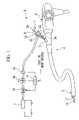
- FIG. 1is a schematic view of an endoscope treatment device that includes the anastomosing instrument according to the present invention.
- FIG. 2is a cross-sectional view showing in the main the structure of the inserted portion of the anastomosing instrument.
- FIG. 3is a cross-sectional view showing in the main the structure of the hand operated portion of the anastomosing instrument.
- FIG. 4is a view showing the locking member, with FIGS. 4A , 4 B and 4 C being perspective, development elevation and cross-sectional views, respectively.
- FIG. 5Ais a view for explaining the anastomosing procedure.
- FIG. 5Bis a view for explaining the positioning of the pushing members.
- FIG. 6Ais a view for explaining the anastomosing procedure.
- FIG. 6Bis a view for explaining the positioning of the pushing members.
- FIG. 7is a view for explaining the anastomosing procedure.
- FIG. 8is a view showing the locking member, with FIGS. 8A and 8B being front and perspective views, respectively.
- FIG. 9is a view showing the locking member, with FIGS. 9A and 9B being front and perspective views, respectively.
- FIG. 10is a perspective view of the locking member.
- FIG. 1is a schematic view of an endoscope treatment device that includes the anastomosing instrument according to the present embodiment.
- FIG. 2is a cross-sectional view showing the inserted portion of the anastomosing instrument.
- FIG. 3is a cross-sectional view showing in the main the hand-operated portion of the anastomosing instrument.
- the present embodiment's anastomosing instrument 1is employed by insertion into the forceps channel 3 of endoscope treatment device 2 .
- Endoscope treatment device 2consists of an endoscope 4 into which anastomosing instrument 1 is inserted, and an air pump 7 which is the flow supplying means for supplying a gas such as air, i.e., the flow, to anastomosing instrument 1 .
- Endoscope 4consists of introduced portion 5 that is introduced into the body cavity and which has a forceps channel 3 , illumination and a camera lens, etc. at one end thereof, and an operating portion 6 for operating introduced portion 5 from outside the body cavity.
- anastomosing instrument 1has a pliable inserted portion 10 that is inserted into a body cavity, and a hand-operated portion 20 which the surgeon operates from outside the body, and is designed so as to permit insertion and passage of pushing members 31 , 32 internally.
- Inserted portion 10has an outer sheath 11 , which is a flexible tube, an inner sheath 12 that is housed inside outer sheath 11 in a manner to permit its advance or withdrawal, and a puncture needle 13 that is attached to the end of inner sheath 12 .
- the end of puncture needle 13is beveled at an acute angle to form a sharp point, thus facilitating penetration into biological tissue.
- Puncture needle 13has a hollow form in which the pointed end thereof has an opening 14 , and an anchoring member 16 and a locking member 17 , which are attached to suture material 15 , are housed internally.
- anchoring member 16consists of a cylindrically-shaped member. One end of suture material 15 for passing through biological tissue is anchored near a center point along the longitudinal direction of anchoring member 16 . During anastomosis, anchoring member 16 comes into contact with the biological tissue in the wide area of its longitudinal direction, and is anchored in the biological tissue, thus preventing suture material 15 from being pulling out from the biological tissue. As a result of this type of shape and function, anchoring member 16 is sometimes referred to as a T-anchor or T-bar.
- Locking member 17functions to prevent suture material 15 from pulling out after anastomosis.
- Locking member 17has two bent pieces 51 , 52 that rise from base 50 at a specific angle and so as to oppose one another. The other end of suture material 15 which is pulled out from anchoring member 16 is pulled through a hole 50 a in base 50 and is passed between bent pieces 51 , 52 .
- this locking member 17has bent pieces 51 , 52 , that are formed by bending the ends in the same direction and along bending lines 53 , 54 that are provided at specific positions on the long side of the plate-shaped part, and a base 50 , which has a contact surface in which the portion having hole 50 a comes into contact with the biological tissue.
- the distance between end 51 a of bent piece 51 and end 52 a of bent piece 52may be set so that when there is no suture material 15 present, ends 51 a and 52 a are in contact with one another, or are separated by a distance that is less than the diameter of suture material 15 .
- FIG. 4Cwhich is a cross-sectional view taken along the line A-A in FIG. 4A
- ends 51 a , 52 awhen the other end of suture material 15 is passed through from base 50 to ends 51 a , 52 a by widening the space between end 51 a and end 52 a , there is a force generated on bent pieces 51 , 52 to bring them closer together. Accordingly, if suture material 15 is pulled in the direction d 1 toward base 50 , ends 51 a , 52 a also move in direction d 1 , causing the distance between ends 51 a , 52 a to narrow. This fastens and locks suture material 15 in place, and prevents its movement.
- locking member 17is moved in a way that closes the space between ends 51 a and 52 a , and functions to lock movement of suture material 15 .
- ends 51 a , 52 afasten on suture material 15 , and the position of locking member 17 with respect to suture material 15 is locked. Therefore, locking member 17 cannot be made to move in the direction d 2 .
- Guide pieces 55 , 56are provided extending from bent pieces 51 , 52 and are for stabilizing and holding suture material 15 in the middle thereof.
- Guide pieces 55 , 56are triangular in shape and are provided with ends 55 a , 56 a that are inclined and extend from the center point of the short sides of the plate-shaped part diagonally to a line that extends from the long sides of the plate-shaped part in FIG. 4B .
- Guide pieces 55 and 56are formed at positions that are symmetrical about a point centered on hole 50 a .
- Inclined ends 55 a , 56a guide suture material 15 so as to stably position it at the center of locking member 17 .
- locking member 17By positioning locking member 17 closer to the end of puncture needle 13 than anchoring member 16 in this embodiment, it is possible to employ a locking member 17 having a larger outer shape than anchoring member 16 . Further, since base 50 of locking member 17 is disposed so as to be parallel to the long direction (axial direction) of puncture needle 13 , the area of base 50 that is in contact with the biological tissue, i.e., the area of contact, can be secured at a maximum limit, even in the limited housing space within puncture needle 13 .
- suture material 15is fixed in place in anchoring member 16 , and, as an end treatment, the other end of suture material 15 is tied into the shape of a ball.
- This end treatmentis carried out after locking member 17 is inserted in a slidable manner, and has the function of preventing falling out of locking member 17 and facilitating gripping by other forceps.
- Other examples of end treatments that can be citedinclude tying the end of suture material 15 into the shape of a ring, or dissolving the end to form it into a clump.
- the pushing member for pushing anchoring member 16 and locking member 17 out from puncture needle 13consists of a first pushing member 31 for pushing out locking member 17 ahead of anchoring member 16 , and a second pushing member 32 for pushing out anchoring member 16 , and is inserted from the hand-operated portion 20 side until it reaches the inner sheath 12 and puncture needle 13 .
- First pushing member 31consists of a pipe having an outer diameter that is smaller than the inner diameter of puncture needle 13 , and houses second pushing member 32 and anchoring member 16 internally in a slidable manner.
- a slit 31 ais provided to the end portion of first pushing member 31 from which suture material 15 , which is attached to anchoring member 16 , is pulled out. Note that it is preferable to provide a clearance sufficient to enable gas flow between first pushing member 31 and the inner wall of puncture needle 13 .
- the hand operated portion 20 shown in FIG. 3consists of a holding member 21 that is connected to outer sheath 11 ; a needle operating portion 22 that is connected to inner sheath 12 and is used for carrying out the operation of advancing and retracting puncture needle 13 ; pushing member handle 23 which is provided to the end of first pushing member 31 and is provided with rings on which the surgeon's fingers rest; and a pushing member knob 24 which is attached to the end of second pushing member 32 .
- Needle operating portion 22is in the form of a cylinder with a base, and a knob 26 in which a groove is formed for the surgeon's fingers to rest is formed to end 22 a which corresponds to this base part. Open end 22 b is connected to inner sheath 12 . Needle operating portion 22 has a gas port 25 on its lateral surface between end 22 a and end 22 b which is the flow introducing portion that is employed when gas is introduced into the space 28 that is formed inside puncture needle operating portion 22 . First pushing member 31 and second pushing member 32 go through puncture needle operating portion 22 so as to pass through from end 22 b to the opening 22 c of end 22 a . The air-tight state between opening 22 c and first pushing member 31 is maintained by packing 27 .
- puncture needle 13can be advanced and retracted inside the body cavity with respect to outer sheath 11 .
- Pushing member handle 23is attached to the outer periphery of first pushing member 31 which is pulled out from puncture needle operating portion 22 .
- Locking member 17can be pushed out from puncture needle 13 by pushing in pushing member handle 23 toward puncture needle operating portion 22 .
- Pushing member knob 24is attached to end 32 b of second pushing member 32 which is pulled out from end 31 b of first pushing member 31 .
- Anchoring member 16can be pushed out from puncture needle 13 by pushing in pushing member knob 24 toward pushing member handle 23 and puncture needle operating portion 22 .
- This gas relaying mechanismfor supplying gas to gas port 25 will now be explained using FIG. 1 .
- This gas relaying mechanismhas an air pump 7 that suctions up air and then discharges it at a specific pressure.
- Electromagnetic valve 8 a for selecting between relay and exhaust, a flow adjusting valve 8 b for adjusting flow of the gas being relayed, and a flow meter 8 c for monitoring the flow quantity of gas actually supplied,are connected in this order by tubing on the discharge side of air pump 7 . Necessary commands are carried out by a CPU (central processing unit) 9 .
- CPU 9carries out switching of electromagnetic valve 8 a and adjustment of the opening of flow adjusting valve 8 b while receiving command signals to start or stop gas relay from a foot or hand switch, and while monitoring flow meter 8 c .
- flow meter 8 c and gas port 25are also connected with tubing.
- FIGS. 5 and 6are figures for explaining the anastomosing procedure and the position of the pushing member at that time.
- FIG. 7is a view for explaining the anastomosing procedure.
- flexible endoscope 2 shown in FIG. 1 and inserted portion 10 of anastomosing instrument 1 shown in FIG. 2are introduced into the body cavity.
- puncture needle operating portion 22 of hand operated portion 20is pulled out from holding member 21 by a specific amount only, so that puncture needle 13 is housed inside outer sheath 11 .
- Pushing member handle 23is pulled out from puncture needle operating portion 22 by a specific amount only, so that first pushing member 31 is drawn back to a position in which it does not apply a pushing force on locking member 17 , and has anchoring member 16 in a housed state therein.
- Pushing member knob 24is pulled out from pushing member handle 23 by just a specific amount, so that second pushing member 32 is retracted back to a position that does not apply a pushing force on anchoring member 16 inside first pushing member 31 .
- the gaspasses through the clearance between first pushing member 31 /inner sheath 12 and puncture needle 13 , and the clearance between locking member 17 and puncture needle 13 , and is discharged from opening 14 at the end of puncture needle 13 .
- locking member 17is in contact with the inner wall of puncture needle 13 in the direction that is orthogonal to the longitudinal direction of puncture needle 13 , so that locking member 17 does not fall out from puncture needle 13 during gas flow, etc.
- puncture needle operating portion 22When puncture needle operating portion 22 is pushed further in, puncture needle 13 penetrates the biological tissue of the organ while discharging gas from the end thereof. Gas is supplied from puncture needle 13 , causing the organ to insufflate. Once it has been determined that a specific quantity of gas has been supplied and the organ has been insufflated to the extent necessary for the procedure, the foot or hand switch (not shown in the figures) is turned OFF and the supply of gas to gas port 25 is halted.
- pushing member handle 23 shown in FIG. 3is pushed toward puncture needle operating portion 22 .
- the end of first pushing member 31applies a pushing force on locking member 17 and locking member 17 is pushed out from opening 14 of puncture needle 13 , as shown in FIG. 5B .
- locking member 17is pushed out on the biological tissue B 1 side which is to be anastomosed.
- puncture needle operating portion 22is pulled back from holding member 21
- puncture needle 13is retracted and is pulled out from biological tissue B 1 .
- suture material 15is passed through biological tissue B 1 , while at the same time locking member 17 is retained in biological tissue B 1 . Since suture material 15 passes through the center of base 50 of locking member 17 , base 50 comes into contact with biological tissue B 1 when suture material 15 is pulled.
- anastomosing instrument 1is moved to a position facing biological tissue B 2 , and needle puncture operating portion 22 is pushed in with respect to holding member 21 .
- puncture needle 13penetrate biological tissue B 2 as shown in FIG. 6A , as gas is being discharged from the end of puncture needle 13 .
- pushing member knob 24see FIG. 3
- second pushing member 32projects out more than the end of first pushing member 31 , as shown in FIG. 6B , and anchoring member 16 which is housed in first pushing member 31 is pushed out from puncture needle 13 .
- puncture needle operating portion 22is pulled back to its original position, so that puncture needle 13 is pulled out from biological tissue B 2 .
- suture material 15is passed through biological tissue B 2 , while at the same time anchoring member 16 is retained in biological tissue B 2 .
- the suture material 15 that extends from locking member 17is gripped by another procedure instrument 70 , which is provided with a forceps 71 housed inside a sheath 72 .
- suture material 15is pulled so as to pull it through locking member 17 .
- this directionis that which widens the space between ends 51 a , 52 a , thus locking member 17 permits movement of suture material 15 .
- anchoring member 16which is tethered to suture material 15 , is pulled, which in turn pulls the biological tissue B 2 that is in contact with anchoring member 16 toward the biological tissue B 1 side.
- biological tissue B 1 and biological tissue B 2are anastomosed as shown in FIG. 7B .
- locking member 17has a wide area of contact with biological tissue B 1 at this time, a reliable anchor effect is realized, and locking member 17 does not cut into biological tissue B 1 .
- this locking member 17moves in such a way that suture material 15 is directed from bent pieces 51 , 52 toward base 50 , it acts to close the space between ends 51 a , 52 a . Accordingly, biological tissue B 1 and biological tissue B 2 do not move in directions away from one another and suture material 15 does not move. Thus, there is no separation of the two anastomosed biological tissues B 1 and B 2 .
- locking member 17may have the shape shown in FIG. 8 .
- the directions of the short legs of a rectangular-shaped membermay be bent in the same way, to form bent pieces 82 , 83 .
- a locking mechanism for fastening and releasing suture material 15 in the same manner as disclosed aboveis realized.
- a base 84which has a thin long shape and the largest area, serves as the contact surface that comes into contact with the biological tissue.
- a hole 92 for passing suture material 15is provided in the center of a narrow long member that is a circular arc in cross-section, and the ends that are orthogonal to the long side are bent in the direction of hole 92 , to form bent pieces 93 , 94 .
- this locking member 91by passing suture material 15 between the ends of bent pieces 93 and 94 , which have been brought close to one another, in a direction extending from the bending position of bent pieces 93 , 94 toward the ends, a locking mechanism equivalent to that disclosed above is realized.
- the surface of this locking member 91 that is opposite hole 92serves as the base, i.e., the contact surface that comes into contact with the biological tissue.
- the locking member 101 shown in FIG. 10has a shape in which a H-shaped cut-out is introduced at the center portion of the narrow long base, and bent pieces 102 , 103 are cut and raised. There is no hole such as described above. However, by passing suture material 15 between the ends of bent pieces 102 and 103 , which have been inclined to be brought close to one another, in a direction extending from the bending position of bent pieces 102 , 103 toward the ends, a locking mechanism equivalent to that disclosed above is realized.
- the portion that excludes bent pieces 102 , 103serves as the base and is the contact surface that comes into contact with the biological tissue.
- the contact surfaceis housed inside puncture needle 13 so as to be parallel to the axial direction thereof. Further, these locking members 81 , 91 and 101 are disposed closer to the end of puncture needle 13 than anchoring member 16 .
- the flow discharged from the end of puncture needle 13may be air or another gas, a liquid such as physiologic saline is also acceptable.
- the surface of the locking member that is in contact with the biological tissueto be parallel to the axial direction of the puncture needle in the anastomosing instrument according to the present invention, the surface area of the locking member that is in contact with the biological tissue can be made larger, and the force for fixing the biological tissue in place can be increased.
- the puncture needlefirst penetrates one of the biological tissues and the locking member is pushed out with the first pushing member. The suture material is then passed through this first biological tissue while the locking member is retained.
- the puncture needlepenetrates the other biological tissue
- the anchoring memberis pushed out with the second pushing member, and the suture material is passed through this other biological tissue while the anchoring member is retained.
- the locking membercan be made larger than the anchoring member and the area that comes into contact with the biological tissue can be increased.
- the biological tissuecan be anastomosed with surety.
- the locking memberin the anastomosing instrument according to the second aspect of the invention, by disposing the locking member to be closer to the end of the puncture needle than the anchoring member in this anastomosing instrument, the locking member can be made larger than the anchoring member, ensuring a large area of contact with the biological tissue. As a result, the biological tissue can be anastomosed with surety.
- the suture materialwhen the suture material is pulled in a direction that closes the space between the ends that are on either side of the suture material, or when the locking member is pushed toward the tissue to be anastomosed, the suture material is fastened between the ends, and relative movement of the locking member is prevented.
- the suture materialwhen the suture material is pulled in a direction that widens the space between the ends, the ends release their fastening on the suture material, and movement of the locking member is permitted. Accordingly, it is possible to fasten the suture material and hold the anastomosed state using a simple structure.
- the anastomosing instrument according to the fourth aspect of the inventionpenetrates biological tissue as flow is being discharged from the end of the puncture needle. As a result, it is possible to insufflate an organ, etc. during instrument penetration.
Landscapes
- Health & Medical Sciences (AREA)
- Life Sciences & Earth Sciences (AREA)
- Surgery (AREA)
- Heart & Thoracic Surgery (AREA)
- Engineering & Computer Science (AREA)
- Biomedical Technology (AREA)
- Nuclear Medicine, Radiotherapy & Molecular Imaging (AREA)
- Medical Informatics (AREA)
- Molecular Biology (AREA)
- Animal Behavior & Ethology (AREA)
- General Health & Medical Sciences (AREA)
- Public Health (AREA)
- Veterinary Medicine (AREA)
- Surgical Instruments (AREA)
Abstract
Description
1. Field of the Invention
The present invention relates to an anastomosing instrument that is introduced into a body cavity via the channel of an endoscope.
This application is based on Japanese Patent Application No. 2003-162009, the contents of which are incorporated herein by reference.
2. Description of the Related Art
Procedure instruments that are inserted into a body cavity and are for suturing biological tissue in order to accomplish hemostasis, for example, are conventionally known. These types of procedure instruments have a puncture needle that can pass through biological tissue, and have a design wherein a suture pull-out preventing tip and fixture are housed in order from the end of the puncture needle (See Japanese Utility Model Application, Second Publication No. 59-21775 (page 3, FIGS. 14 and 23)).
In this kind of procedure instrument, the puncture needle is passed through two biological tissues that are to be anastomosed, and the pull-out preventing tip is pushed out from the puncture needle first. The fixture is subsequently pushed out of the puncture needle once the puncture needle is pulled out from the two biological tissues. Finally, the suture material is pulled, anastomosing the two biological tissues, which are then held with the fixture. As examples of fixtures, devices have been disclosed that house a tapered elastic fastening member inside a member having a tapered cavity, and hold the suture by means of the frictional force between these two members.
The first aspect of the invention is an anastomosing instrument in which an anchoring member, that is attached to one end of a suture material and is for anchoring in a biological tissue, and a locking member, through which the other end of the suture material is inserted and that comes into contact with the anastomosed biological tissue to function to prevent pull-out of the suture, are housed inside a puncture needle, wherein, once the puncture needle has passed through the biological tissue, the suture material is passed through the biological tissue as the anchoring member and the locking member are pushed out in accordance with operations from a hand held portion, thereby anastomosing the biological tissues; this anastomosing instrument characterized in that the locking member is disposed in the internal cavity of the puncture needle so that the surface of the locking member that is in contact with the biological tissue will be parallel to the axial direction of the puncture needle, and in the provision of a first pushing member that pushes out the locking member from the puncture needle and a second pushing member that is housed inside the first pushing member and pushes out the anchoring member from the puncture needle.
The second aspect of the invention is characterized in that, in the anastomosing instrument of the first aspect, the locking member and the anchoring member are disposed in this order from the end of the puncture needle, lying along the longitudinal direction of the puncture needle.
The third aspect of the invention is characterized in that, in the anastomosing instrument of the first aspect, the locking member has two bent pieces that are inclined with respect to its base so as be opposite one another, wherein these bent pieces are designed so that a suture material that was passed between the ends thereof is fastened when a force is applied to close the space between the opposing ends, and the fastening of the suture material is released when a force is applied to widen the space between the opposing ends.
The fourth aspect of the invention is characterized in that an anastomosing instrument of the first aspect is designed to have a flow introducing portion provided on the hand-held side for supplying flow to the puncture needle, and for gas to be discharged from the end of the puncture needle.
Embodiments of the present invention will now be explained in detail with reference to the figures.FIG. 1 is a schematic view of an endoscope treatment device that includes the anastomosing instrument according to the present embodiment.FIG. 2 is a cross-sectional view showing the inserted portion of the anastomosing instrument.FIG. 3 is a cross-sectional view showing in the main the hand-operated portion of the anastomosing instrument.
As shown inFIG. 1 , the present embodiment'sanastomosing instrument 1 is employed by insertion into theforceps channel 3 ofendoscope treatment device 2.Endoscope treatment device 2 consists of anendoscope 4 into which anastomosinginstrument 1 is inserted, and an air pump7 which is the flow supplying means for supplying a gas such as air, i.e., the flow, to anastomosinginstrument 1.Endoscope 4 consists of introducedportion 5 that is introduced into the body cavity and which has aforceps channel 3, illumination and a camera lens, etc. at one end thereof, and an operating portion6 for operating introducedportion 5 from outside the body cavity.
As shown inFIGS. 2 and 3 ,anastomosing instrument 1 has a pliable insertedportion 10 that is inserted into a body cavity, and a hand-operatedportion 20 which the surgeon operates from outside the body, and is designed so as to permit insertion and passage of pushingmembers
Insertedportion 10 has anouter sheath 11, which is a flexible tube, aninner sheath 12 that is housed insideouter sheath 11 in a manner to permit its advance or withdrawal, and apuncture needle 13 that is attached to the end ofinner sheath 12. The end ofpuncture needle 13 is beveled at an acute angle to form a sharp point, thus facilitating penetration into biological tissue.Puncture needle 13 has a hollow form in which the pointed end thereof has anopening 14, and ananchoring member 16 and alocking member 17, which are attached tosuture material 15, are housed internally.
As shown inFIGS. 2 and 4A , anchoringmember 16 consists of a cylindrically-shaped member. One end ofsuture material 15 for passing through biological tissue is anchored near a center point along the longitudinal direction of anchoringmember 16. During anastomosis, anchoringmember 16 comes into contact with the biological tissue in the wide area of its longitudinal direction, and is anchored in the biological tissue, thus preventingsuture material 15 from being pulling out from the biological tissue. As a result of this type of shape and function, anchoringmember 16 is sometimes referred to as a T-anchor or T-bar.
Lockingmember 17 functions to preventsuture material 15 from pulling out after anastomosis.Locking member 17 has twobent pieces base 50 at a specific angle and so as to oppose one another. The other end ofsuture material 15 which is pulled out from anchoringmember 16 is pulled through ahole 50ainbase 50 and is passed betweenbent pieces hole 50afor passing the suture material that is formed in the center of the plate-shaped part of thislocking member 17, and thislocking member 17 hasbent pieces lines base 50, which has a contact surface in which theportion having hole 50acomes into contact with the biological tissue. The distance betweenend 51aofbent piece 51 andend 52aofbent piece 52 may be set so that when there is nosuture material 15 present,ends suture material 15.
As shown inFIG. 4C , which is a cross-sectional view taken along the line A-A inFIG. 4A , when the other end ofsuture material 15 is passed through frombase 50 toends end 51aandend 52a, there is a force generated onbent pieces suture material 15 is pulled in the direction d1 towardbase 50,ends ends locks suture material 15 in place, and prevents its movement. In other words, in the case where there is a force working onsuture material 15 that will pull apart anchoringmember 16 and lockingmember 17,locking member 17 is moved in a way that closes the space betweenends suture material 15. To restate, even if the target of anastomosis that is held between lockingmember 17 and anchoringmember 16pushes locking member 17 in the direction d2 toward the other end ofsuture material 15, ends51a,52afasten onsuture material 15, and the position of lockingmember 17 with respect tosuture material 15 is locked. Therefore, lockingmember 17 cannot be made to move in the direction d2.
On the other hand, whensuture material 15 is pulled in direction d2 which isopposite base 50, ends51aand52aalso move in direction d2 (i.e., a direction which moves them away from each other). As a result, their fastening onsuture material 15 is released. In other words, movement ofsuture material 15 is permitted in the direction which brings anchoringmember 16 and lockingmember 17 closer to one another. To restate, when lockingmember 17 is pushed toward the tissue to be anastomosed, i.e., when lockingmember 17 is moved in direction d1 toward the one end ofsuture material 15, the space betweenend 51aand end52awidens, and the fastening ofends suture material 15 is released. As a result, lockingmember 17 can move in direction d1.
By positioning lockingmember 17 closer to the end ofpuncture needle 13 than anchoringmember 16 in this embodiment, it is possible to employ a lockingmember 17 having a larger outer shape than anchoringmember 16. Further, sincebase 50 of lockingmember 17 is disposed so as to be parallel to the long direction (axial direction) ofpuncture needle 13, the area ofbase 50 that is in contact with the biological tissue, i.e., the area of contact, can be secured at a maximum limit, even in the limited housing space withinpuncture needle 13.
One end ofsuture material 15 is fixed in place in anchoringmember 16, and, as an end treatment, the other end ofsuture material 15 is tied into the shape of a ball. This end treatment is carried out after lockingmember 17 is inserted in a slidable manner, and has the function of preventing falling out of lockingmember 17 and facilitating gripping by other forceps. Other examples of end treatments that can be cited include tying the end ofsuture material 15 into the shape of a ring, or dissolving the end to form it into a clump.
As shown inFIGS. 2 and 3 , the pushing member for pushing anchoringmember 16 and lockingmember 17 out frompuncture needle 13 consists of a first pushingmember 31 for pushing out lockingmember 17 ahead of anchoringmember 16, and a second pushingmember 32 for pushing out anchoringmember 16, and is inserted from the hand-operatedportion 20 side until it reaches theinner sheath 12 and punctureneedle 13. First pushingmember 31 consists of a pipe having an outer diameter that is smaller than the inner diameter ofpuncture needle 13, and houses second pushingmember 32 and anchoringmember 16 internally in a slidable manner. For this reason, aslit 31ais provided to the end portion of first pushingmember 31 from which suturematerial 15, which is attached to anchoringmember 16, is pulled out. Note that it is preferable to provide a clearance sufficient to enable gas flow between first pushingmember 31 and the inner wall ofpuncture needle 13.
The hand operatedportion 20 shown inFIG. 3 consists of a holdingmember 21 that is connected toouter sheath 11; aneedle operating portion 22 that is connected toinner sheath 12 and is used for carrying out the operation of advancing and retractingpuncture needle 13; pushing member handle23 which is provided to the end of first pushingmember 31 and is provided with rings on which the surgeon's fingers rest; and a pushingmember knob 24 which is attached to the end of second pushingmember 32.
Pushing member handle23 is attached to the outer periphery of first pushingmember 31 which is pulled out from punctureneedle operating portion 22. Lockingmember 17 can be pushed out frompuncture needle 13 by pushing in pushing member handle23 toward punctureneedle operating portion 22. Pushingmember knob 24 is attached to end32bof second pushingmember 32 which is pulled out fromend 31bof first pushingmember 31. Anchoringmember 16 can be pushed out frompuncture needle 13 by pushing in pushingmember knob 24 toward pushing member handle23 and punctureneedle operating portion 22.
The gas relaying mechanism for supplying gas togas port 25 will now be explained usingFIG. 1 . This gas relaying mechanism has an air pump7 that suctions up air and then discharges it at a specific pressure.Electromagnetic valve 8afor selecting between relay and exhaust, aflow adjusting valve 8bfor adjusting flow of the gas being relayed, and aflow meter 8cfor monitoring the flow quantity of gas actually supplied, are connected in this order by tubing on the discharge side of air pump7. Necessary commands are carried out by a CPU (central processing unit)9.CPU 9 carries out switching ofelectromagnetic valve 8aand adjustment of the opening offlow adjusting valve 8bwhile receiving command signals to start or stop gas relay from a foot or hand switch, and while monitoringflow meter 8c. Note thatflow meter 8candgas port 25 are also connected with tubing.
Next, the sequence for suturing tissues such as internal organs with thisanastomosing instrument 1 will be explained with suitable reference toFIGS. 1 through 3 andFIGS. 5 ,6, and7. Note thatFIGS. 5 and 6 are figures for explaining the anastomosing procedure and the position of the pushing member at that time.FIG. 7 is a view for explaining the anastomosing procedure.
First,flexible endoscope 2 shown inFIG. 1 and insertedportion 10 of anastomosinginstrument 1 shown inFIG. 2 are introduced into the body cavity. At this time, punctureneedle operating portion 22 of hand operatedportion 20 is pulled out from holdingmember 21 by a specific amount only, so thatpuncture needle 13 is housed insideouter sheath 11. Pushing member handle23 is pulled out from punctureneedle operating portion 22 by a specific amount only, so that first pushingmember 31 is drawn back to a position in which it does not apply a pushing force on lockingmember 17, and has anchoringmember 16 in a housed state therein. Pushingmember knob 24 is pulled out from pushing member handle23 by just a specific amount, so that second pushingmember 32 is retracted back to a position that does not apply a pushing force on anchoringmember 16 inside first pushingmember 31.
From this state, the end ofouter sheath 11 is moved to a position facing the biological tissue that is to be anastomosed, and punctureneedle operating portion 22 is then pushed forward toward holdingmember 21 by a specific amount, thereby exposingpuncture needle 13 fromouter sheath 11. A foot or hand switch, not shown in the figures, is turned ON, and gas discharged by air pump7 shown inFIG. 1 is directed togas port 25. The gas directed togas port 25 is introduced toinner sheath 12 of insertedportion 10 via thespace 28 in the punctureneedle operating portion 22 shown inFIG. 3 . The gas passes through the clearance between first pushingmember 31/inner sheath 12 and punctureneedle 13, and the clearance between lockingmember 17 and punctureneedle 13, and is discharged from opening14 at the end ofpuncture needle 13. Note that lockingmember 17 is in contact with the inner wall ofpuncture needle 13 in the direction that is orthogonal to the longitudinal direction ofpuncture needle 13, so that lockingmember 17 does not fall out frompuncture needle 13 during gas flow, etc.
When punctureneedle operating portion 22 is pushed further in, punctureneedle 13 penetrates the biological tissue of the organ while discharging gas from the end thereof. Gas is supplied frompuncture needle 13, causing the organ to insufflate. Once it has been determined that a specific quantity of gas has been supplied and the organ has been insufflated to the extent necessary for the procedure, the foot or hand switch (not shown in the figures) is turned OFF and the supply of gas togas port 25 is halted.
With the organ in an insufflated state, pushing member handle23 shown inFIG. 3 is pushed toward punctureneedle operating portion 22. As a result, the end of first pushingmember 31 applies a pushing force on lockingmember 17 and lockingmember 17 is pushed out from opening14 ofpuncture needle 13, as shown inFIG. 5B . As shown inFIG. 5A , lockingmember 17 is pushed out on the biological tissue B1 side which is to be anastomosed. Thus, when punctureneedle operating portion 22 is pulled back from holdingmember 21,puncture needle 13 is retracted and is pulled out from biological tissue B1. As a result,suture material 15 is passed through biological tissue B1, while at the sametime locking member 17 is retained in biological tissue B1. Sincesuture material 15 passes through the center ofbase 50 of lockingmember 17,base 50 comes into contact with biological tissue B1 whensuture material 15 is pulled.
Next, in operating steps not shown in the figures,anastomosing instrument 1 is moved to a position facing biological tissue B2, and needlepuncture operating portion 22 is pushed in with respect to holdingmember 21. As a result,puncture needle 13 penetrate biological tissue B2 as shown inFIG. 6A , as gas is being discharged from the end ofpuncture needle 13. When pushing member knob24 (seeFIG. 3 ) is pushed in toward pushing member handle23, second pushingmember 32 projects out more than the end of first pushingmember 31, as shown inFIG. 6B , and anchoringmember 16 which is housed in first pushingmember 31 is pushed out frompuncture needle 13. Thereafter, punctureneedle operating portion 22 is pulled back to its original position, so thatpuncture needle 13 is pulled out from biological tissue B2.
As a result, as shown inFIG. 7A ,suture material 15 is passed through biological tissue B2, while at the sametime anchoring member 16 is retained in biological tissue B2. Thesuture material 15 that extends from lockingmember 17 is gripped by anotherprocedure instrument 70, which is provided with aforceps 71 housed inside asheath 72. With lockingmember 17 being pushed by the end ofsheath 72 so thatbase 50 comes into contact with biological tissue B1,suture material 15 is pulled so as to pull it through lockingmember 17. As disclosed above, this direction is that which widens the space between ends51a,52a, thus lockingmember 17 permits movement ofsuture material 15. Accordingly, anchoringmember 16, which is tethered to suturematerial 15, is pulled, which in turn pulls the biological tissue B2 that is in contact with anchoringmember 16 toward the biological tissue B1 side. As a result, biological tissue B1 and biological tissue B2 are anastomosed as shown inFIG. 7B . Since lockingmember 17 has a wide area of contact with biological tissue B1 at this time, a reliable anchor effect is realized, and lockingmember 17 does not cut into biological tissue B1. Further, as disclosed above, when this lockingmember 17 moves in such a way that suturematerial 15 is directed frombent pieces base 50, it acts to close the space between ends51a,52a. Accordingly, biological tissue B1 and biological tissue B2 do not move in directions away from one another andsuture material 15 does not move. Thus, there is no separation of the two anastomosed biological tissues B1 and B2.
Note that the present invention is not limited to the embodiments described above, but rather has a wide variety of applications.
For example, lockingmember 17 may have the shape shown inFIG. 8 . In the lockingmember 81 shown inFIGS. 8A and 8B , the directions of the short legs of a rectangular-shaped member may be bent in the same way, to formbent pieces suture material 15 between the ends ofbent pieces bent pieces suture material 15 in the same manner as disclosed above is realized. In this case, abase 84, which has a thin long shape and the largest area, serves as the contact surface that comes into contact with the biological tissue.
In the lockingmember 91 shown inFIGS. 9A and 9B , ahole 92 for passingsuture material 15 is provided in the center of a narrow long member that is a circular arc in cross-section, and the ends that are orthogonal to the long side are bent in the direction ofhole 92, to formbent pieces member 91 as well, by passingsuture material 15 between the ends ofbent pieces bent pieces member 91 that isopposite hole 92 serves as the base, i.e., the contact surface that comes into contact with the biological tissue.
The lockingmember 101 shown inFIG. 10 has a shape in which a H-shaped cut-out is introduced at the center portion of the narrow long base, andbent pieces suture material 15 between the ends ofbent pieces bent pieces
In this lockingmember 101, the portion that excludesbent pieces members FIGS. 8 through 10 , the contact surface is housed insidepuncture needle 13 so as to be parallel to the axial direction thereof. Further, these lockingmembers puncture needle 13 than anchoringmember 16.
While the flow discharged from the end ofpuncture needle 13 may be air or another gas, a liquid such as physiologic saline is also acceptable.
As explained above, in the anastomosing instrument according to the first aspect of the invention, by disposing the surface of the locking member that is in contact with the biological tissue to be parallel to the axial direction of the puncture needle in the anastomosing instrument according to the present invention, the surface area of the locking member that is in contact with the biological tissue can be made larger, and the force for fixing the biological tissue in place can be increased. When anastomosing two biological tissues, the puncture needle first penetrates one of the biological tissues and the locking member is pushed out with the first pushing member. The suture material is then passed through this first biological tissue while the locking member is retained. Next, the puncture needle penetrates the other biological tissue, the anchoring member is pushed out with the second pushing member, and the suture material is passed through this other biological tissue while the anchoring member is retained. Accordingly, the locking member can be made larger than the anchoring member and the area that comes into contact with the biological tissue can be increased. As a result, the biological tissue can be anastomosed with surety.
In the anastomosing instrument according to the second aspect of the invention, by disposing the locking member to be closer to the end of the puncture needle than the anchoring member in this anastomosing instrument, the locking member can be made larger than the anchoring member, ensuring a large area of contact with the biological tissue. As a result, the biological tissue can be anastomosed with surety.
In the anastomosing instrument according to the third aspect of the invention, when the suture material is pulled in a direction that closes the space between the ends that are on either side of the suture material, or when the locking member is pushed toward the tissue to be anastomosed, the suture material is fastened between the ends, and relative movement of the locking member is prevented. On the other hand, when the suture material is pulled in a direction that widens the space between the ends, the ends release their fastening on the suture material, and movement of the locking member is permitted. Accordingly, it is possible to fasten the suture material and hold the anastomosed state using a simple structure.
The anastomosing instrument according to the fourth aspect of the invention penetrates biological tissue as flow is being discharged from the end of the puncture needle. As a result, it is possible to insufflate an organ, etc. during instrument penetration.
In the invention according to the fourth aspect, it is possible to insufflate the organ, etc. during needle penetration, so that it is possible to penetrate only the target tissue with surety and carry out the anastomosing procedure.
Claims (3)
1. An anastomosing device comprising:
an anchoring member;
a suture material, said anchoring member being attached to a first end of said suture material and being adapted to anchor in a biological tissue;
a puncture needle;
a locking member, through which a second end of said suture material is inserted and that comes into contact with the anastomosed biological tissue so as to prevent pull-out of the suture material, said anchoring member and said locking member being housed inside said puncture needle, wherein, once said puncture needle has passed through the biological tissues, said suture material is passed through the biological tissues as said anchoring member and said locking member are pushed out in accordance with operations from a hand held portion, thereby anastomosing said biological tissues,
said locking member being disposed in the internal cavity of said puncture needle so that the surface of said locking member that is in contact with said biological tissue becomes parallel to the axial direction of said puncture needle;
a first pushing member that pushes out said locking member from said puncture needle; and
a second pushing member that is housed inside said first pushing member and pushes out said anchoring member from said puncture needle;
wherein said locking member comprises a base and two bent pieces that are inclined with respect to said base so as to be opposite one another, said bent pieces being adapted such that the suture material that is passed between ends thereof is fastened when a force is applied so as to close the space between the opposing said ends, and the fastening of said suture material is released when a force is applied to as to widen the space between the opposing said ends, and
wherein said locking member and said anchoring member are disposed substantially in line within said puncture needle such that said locking member is closer than said anchoring member relative to a piercing end of said puncture needle.
2. The anastomosing device according toclaim 1 , wherein a flow introducing portion on a side of said hand-held portion for supplying flow to the puncture needle is provided, and gas is discharged from a piercing end of said puncture needle.
3. The anastomosing device according toclaim 1 , wherein said base and said two bent pieces are formed in a single piece.
Applications Claiming Priority (2)
| Application Number | Priority Date | Filing Date | Title |
|---|---|---|---|
| JP2003-162009 | 2003-06-06 | ||
| JP2003162009AJP4166632B2 (en) | 2003-06-06 | 2003-06-06 | Suture device |
Publications (2)
| Publication Number | Publication Date |
|---|---|
| US20040249392A1 US20040249392A1 (en) | 2004-12-09 |
| US7534248B2true US7534248B2 (en) | 2009-05-19 |
Family
ID=33157215
Family Applications (1)
| Application Number | Title | Priority Date | Filing Date |
|---|---|---|---|
| US10/859,849Expired - LifetimeUS7534248B2 (en) | 2003-06-06 | 2004-06-03 | Anastomosing instrument |
Country Status (3)
| Country | Link |
|---|---|
| US (1) | US7534248B2 (en) |
| EP (1) | EP1484023B1 (en) |
| JP (1) | JP4166632B2 (en) |
Cited By (36)
| Publication number | Priority date | Publication date | Assignee | Title |
|---|---|---|---|---|
| US20050216042A1 (en)* | 2004-03-23 | 2005-09-29 | Michael Gertner | Percutaneous gastroplasty |
| US20050285604A1 (en)* | 2004-06-29 | 2005-12-29 | Ryoichi Shinohara | Partial discharge detecting sensor and gas insulated electric apparatus provided with a partial discharge detecting sensor |
| US20060100643A1 (en)* | 2004-03-11 | 2006-05-11 | Laufer Michael D | Surgical fastening system |
| US20060142790A1 (en)* | 2004-03-23 | 2006-06-29 | Michael Gertner | Methods and devices to facilitate connections between body lumens |
| US20060195139A1 (en)* | 2004-03-23 | 2006-08-31 | Michael Gertner | Extragastric devices and methods for gastroplasty |
| US20070073319A1 (en)* | 2005-09-28 | 2007-03-29 | Olympus Medical Systems Corp. | Method for suturing perforation and suture instrument |
| US20070233170A1 (en)* | 2004-03-23 | 2007-10-04 | Michael Gertner | Extragastric Balloon |
| US20080262520A1 (en)* | 2006-04-19 | 2008-10-23 | Joshua Makower | Devices and methods for treatment of obesity |
| US20080262515A1 (en)* | 2006-12-28 | 2008-10-23 | Joshua Makower | Devices and methods for treatment of obesity |
| US20090018574A1 (en)* | 2007-06-15 | 2009-01-15 | Zerusa Limited | Closure device |
| US20090036910A1 (en)* | 2006-04-19 | 2009-02-05 | Vibrynt, Inc. | Devices and Methods for Treatment of Obesity |
| US20090281377A1 (en)* | 2006-04-19 | 2009-11-12 | Newell Matthew B | Devices, tools and methods for performing minimally invasive abdominal surgical procedures |
| US20090281498A1 (en)* | 2006-04-19 | 2009-11-12 | Acosta Pablo G | Devices, system and methods for minimally invasive abdominal surgical procedures |
| US20090287227A1 (en)* | 2006-04-19 | 2009-11-19 | Newell Matthew B | Minimally invasive ,methods for implanting obesity treatment devices |
| US20100130989A1 (en)* | 2008-11-26 | 2010-05-27 | Smith & Nephew, Inc. | Tissue Repair Device |
| US20100234682A1 (en)* | 2004-03-23 | 2010-09-16 | Michael Gertner | Closed loop gastric restriction devices and methods |
| US7946976B2 (en) | 2004-03-23 | 2011-05-24 | Michael Gertner | Methods and devices for the surgical creation of satiety and biofeedback pathways |
| US7976554B2 (en) | 2006-04-19 | 2011-07-12 | Vibrynt, Inc. | Devices, tools and methods for performing minimally invasive abdominal surgical procedures |
| US8187297B2 (en) | 2006-04-19 | 2012-05-29 | Vibsynt, Inc. | Devices and methods for treatment of obesity |
| US8382775B1 (en) | 2012-01-08 | 2013-02-26 | Vibrynt, Inc. | Methods, instruments and devices for extragastric reduction of stomach volume |
| US8398668B2 (en) | 2006-04-19 | 2013-03-19 | Vibrynt, Inc. | Devices and methods for treatment of obesity |
| US20130245534A1 (en)* | 2011-01-11 | 2013-09-19 | Amsel Medical Corporation | Injectable valve and other flow control elements |
| US8556925B2 (en) | 2007-10-11 | 2013-10-15 | Vibrynt, Inc. | Devices and methods for treatment of obesity |
| US20150094740A1 (en)* | 2012-04-04 | 2015-04-02 | Paul J. GAGNE | Methods and Systems for Ligating a Blood Vessel |
| US9060751B2 (en) | 2010-12-30 | 2015-06-23 | Vivasure Medical Limited | Surgical closure systems and methods |
| US9265514B2 (en) | 2012-04-17 | 2016-02-23 | Miteas Ltd. | Manipulator for grasping tissue |
| US9314362B2 (en) | 2012-01-08 | 2016-04-19 | Vibrynt, Inc. | Methods, instruments and devices for extragastric reduction of stomach volume |
| US9572558B2 (en) | 2012-02-29 | 2017-02-21 | Vivasure Medical Limited | Devices and methods for delivering implants for percutaneous perforation closure |
| US9833231B2 (en) | 1999-12-02 | 2017-12-05 | Smith & Nephew, Inc. | Apparatus for tissue repair |
| US9850013B2 (en) | 2013-03-15 | 2017-12-26 | Vivasure Medical Limited | Loading devices and methods for percutaneous perforation closure systems |
| US10098628B2 (en) | 2014-07-22 | 2018-10-16 | Cook Medical Technologies Llc | Anchor deployment system, device, and method of treatment |
| US10206668B2 (en) | 2014-12-15 | 2019-02-19 | Vivasure Medical Limited | Implantable sealable member with mesh layer |
| US10433826B2 (en) | 2014-12-15 | 2019-10-08 | Vivasure Medical Limited | Closure apparatus with flexible sealable member and flexible support member |
| US11304691B2 (en) | 2016-11-13 | 2022-04-19 | Anchora Medical Ltd. | Minimally-invasive tissue suturing device |
| US11311280B2 (en) | 2015-12-15 | 2022-04-26 | Vivasure Medical Limited | Arteriotomy closure apparatus with slotted shoe for advantageous pressure distribution |
| US11357486B2 (en) | 2009-12-30 | 2022-06-14 | Vivasure Medical Limited | Closure system and uses thereof |
Families Citing this family (107)
| Publication number | Priority date | Publication date | Assignee | Title |
|---|---|---|---|---|
| US7618426B2 (en) | 2002-12-11 | 2009-11-17 | Usgi Medical, Inc. | Apparatus and methods for forming gastrointestinal tissue approximations |
| US7637905B2 (en) | 2003-01-15 | 2009-12-29 | Usgi Medical, Inc. | Endoluminal tool deployment system |
| US7744613B2 (en) | 1999-06-25 | 2010-06-29 | Usgi Medical, Inc. | Apparatus and methods for forming and securing gastrointestinal tissue folds |
| US7160312B2 (en)* | 1999-06-25 | 2007-01-09 | Usgi Medical, Inc. | Implantable artificial partition and methods of use |
| US7416554B2 (en) | 2002-12-11 | 2008-08-26 | Usgi Medical Inc | Apparatus and methods for forming and securing gastrointestinal tissue folds |
| US7942898B2 (en) | 2002-12-11 | 2011-05-17 | Usgi Medical, Inc. | Delivery systems and methods for gastric reduction |
| US7942884B2 (en) | 2002-12-11 | 2011-05-17 | Usgi Medical, Inc. | Methods for reduction of a gastric lumen |
| US8512118B2 (en)* | 2003-06-19 | 2013-08-20 | Aristocrat Technologies Australia Pty Limited | Cashless reservation system |
| US8216252B2 (en) | 2004-05-07 | 2012-07-10 | Usgi Medical, Inc. | Tissue manipulation and securement system |
| TW200506345A (en)* | 2003-08-14 | 2005-02-16 | Au Optronics Corp | Water quality analysis method using potassium permanganate |
| US7736372B2 (en)* | 2003-11-13 | 2010-06-15 | Usgi Medical, Inc. | Apparatus and methods for endoscopic suturing |
| US7347863B2 (en) | 2004-05-07 | 2008-03-25 | Usgi Medical, Inc. | Apparatus and methods for manipulating and securing tissue |
| US7361180B2 (en) | 2004-05-07 | 2008-04-22 | Usgi Medical, Inc. | Apparatus for manipulating and securing tissue |
| US20050251189A1 (en) | 2004-05-07 | 2005-11-10 | Usgi Medical Inc. | Multi-position tissue manipulation assembly |
| US7520884B2 (en) | 2004-05-07 | 2009-04-21 | Usgi Medical Inc. | Methods for performing gastroplasty |
| US8257394B2 (en) | 2004-05-07 | 2012-09-04 | Usgi Medical, Inc. | Apparatus and methods for positioning and securing anchors |
| US8057511B2 (en) | 2004-05-07 | 2011-11-15 | Usgi Medical, Inc. | Apparatus and methods for positioning and securing anchors |
| US7390329B2 (en) | 2004-05-07 | 2008-06-24 | Usgi Medical, Inc. | Methods for grasping and cinching tissue anchors |
| US8444657B2 (en) | 2004-05-07 | 2013-05-21 | Usgi Medical, Inc. | Apparatus and methods for rapid deployment of tissue anchors |
| US7736374B2 (en) | 2004-05-07 | 2010-06-15 | Usgi Medical, Inc. | Tissue manipulation and securement system |
| US20050251159A1 (en)* | 2004-05-07 | 2005-11-10 | Usgi Medical Inc. | Methods and apparatus for grasping and cinching tissue anchors |
| US7918869B2 (en) | 2004-05-07 | 2011-04-05 | Usgi Medical, Inc. | Methods and apparatus for performing endoluminal gastroplasty |
| US7695493B2 (en) | 2004-06-09 | 2010-04-13 | Usgi Medical, Inc. | System for optimizing anchoring force |
| US8603106B2 (en) | 2005-05-20 | 2013-12-10 | Neotract, Inc. | Integrated handle assembly for anchor delivery system |
| US8628542B2 (en) | 2005-05-20 | 2014-01-14 | Neotract, Inc. | Median lobe destruction apparatus and method |
| US10925587B2 (en) | 2005-05-20 | 2021-02-23 | Neotract, Inc. | Anchor delivery system |
| US10195014B2 (en) | 2005-05-20 | 2019-02-05 | Neotract, Inc. | Devices, systems and methods for treating benign prostatic hyperplasia and other conditions |
| US8425535B2 (en) | 2005-05-20 | 2013-04-23 | Neotract, Inc. | Multi-actuating trigger anchor delivery system |
| US9504461B2 (en) | 2005-05-20 | 2016-11-29 | Neotract, Inc. | Anchor delivery system |
| US7758594B2 (en) | 2005-05-20 | 2010-07-20 | Neotract, Inc. | Devices, systems and methods for treating benign prostatic hyperplasia and other conditions |
| US9549739B2 (en) | 2005-05-20 | 2017-01-24 | Neotract, Inc. | Devices, systems and methods for treating benign prostatic hyperplasia and other conditions |
| US8945152B2 (en) | 2005-05-20 | 2015-02-03 | Neotract, Inc. | Multi-actuating trigger anchor delivery system |
| US8668705B2 (en) | 2005-05-20 | 2014-03-11 | Neotract, Inc. | Latching anchor device |
| US7645286B2 (en) | 2005-05-20 | 2010-01-12 | Neotract, Inc. | Devices, systems and methods for retracting, lifting, compressing, supporting or repositioning tissues or anatomical structures |
| US9585651B2 (en) | 2005-05-26 | 2017-03-07 | Usgi Medical, Inc. | Methods and apparatus for securing and deploying tissue anchors |
| US8298291B2 (en) | 2005-05-26 | 2012-10-30 | Usgi Medical, Inc. | Methods and apparatus for securing and deploying tissue anchors |
| EP2135560B1 (en) | 2005-06-02 | 2011-08-10 | Cordis Corporation | Medical device for deploying a mechanical closure devcie |
| AU2006269384B2 (en)* | 2005-07-07 | 2012-03-29 | Cardinal Health 529, Llc | Patent foramen ovale closure device with steerable delivery system |
| EP1749481A1 (en) | 2005-08-02 | 2007-02-07 | Marco Gandini | Suture device |
| CA2621197A1 (en) | 2005-09-01 | 2007-03-08 | Cordis Corporation | Patent foramen ovale closure method |
| US7815659B2 (en) | 2005-11-15 | 2010-10-19 | Ethicon Endo-Surgery, Inc. | Suture anchor applicator |
| US7785333B2 (en) | 2006-02-21 | 2010-08-31 | Olympus Medical Systems Corp. | Overtube and operative procedure via bodily orifice |
| US20070167676A1 (en)* | 2006-01-13 | 2007-07-19 | Olympus Medical Systems Corp. | Overtube and medical procedure via natural orifice using the same |
| US20070213702A1 (en)* | 2006-03-08 | 2007-09-13 | Olympus Medical Systems Corp. | Medical procedure carried out via a natural opening |
| US20070219411A1 (en)* | 2006-01-13 | 2007-09-20 | Olympus Medical Systems Corp. | Overtube and endoscopic treatment system |
| US20080255422A1 (en)* | 2006-01-13 | 2008-10-16 | Olympus Medical Systems Corp. | Medical device |
| US8721657B2 (en) | 2006-01-13 | 2014-05-13 | Olympus Medical Systems Corp. | Medical instrument |
| US8728121B2 (en)* | 2006-01-13 | 2014-05-20 | Olympus Medical Systems Corp. | Puncture needle and medical procedure using puncture needle that is performed via natural orifice |
| US20070167675A1 (en)* | 2006-01-13 | 2007-07-19 | Olympus Medical Systems Corp. | Overtube and medical procedure via natural orifice using the same |
| US8241279B2 (en) | 2006-02-23 | 2012-08-14 | Olympus Medical Systems Corp. | Overtube and natural opening medical procedures using the same |
| US8726909B2 (en) | 2006-01-27 | 2014-05-20 | Usgi Medical, Inc. | Methods and apparatus for revision of obesity procedures |
| EP2019629B1 (en)* | 2006-04-28 | 2012-02-22 | Covidien AG | Organopexy tool set |
| US8105355B2 (en) | 2006-05-18 | 2012-01-31 | C.R. Bard, Inc. | Suture lock fastening device |
| US8870916B2 (en) | 2006-07-07 | 2014-10-28 | USGI Medical, Inc | Low profile tissue anchors, tissue anchor systems, and methods for their delivery and use |
| JP5073415B2 (en)* | 2006-08-28 | 2012-11-14 | オリンパスメディカルシステムズ株式会社 | Ultrasound endoscope |
| US20080103527A1 (en)* | 2006-10-27 | 2008-05-01 | Martin David T | Flexible endoscopic suture anchor applier |
| US8308766B2 (en) | 2007-02-27 | 2012-11-13 | Olympus Medical Systems Corp. | Endoscopic treatment instrument |
| US7780702B2 (en) | 2007-02-27 | 2010-08-24 | Olympus Medical Systems Corp. | Suture tool |
| US8128657B2 (en) | 2007-02-27 | 2012-03-06 | Olympus Medical Systems Corp. | Suture instrument |
| US10441273B2 (en) | 2007-07-03 | 2019-10-15 | Ceterix Orthopaedics, Inc. | Pre-tied surgical knots for use with suture passers |
| US9314234B2 (en) | 2007-07-03 | 2016-04-19 | Ceterix Orthopaedics, Inc. | Pre-tied surgical knots for use with suture passers |
| US9211119B2 (en) | 2007-07-03 | 2015-12-15 | Ceterix Orthopaedics, Inc. | Suture passers and methods of passing suture |
| US8465505B2 (en) | 2011-05-06 | 2013-06-18 | Ceterix Orthopaedics, Inc. | Suture passer devices and methods |
| US8821518B2 (en) | 2007-11-05 | 2014-09-02 | Ceterix Orthopaedics, Inc. | Suture passing instrument and method |
| US8500809B2 (en) | 2011-01-10 | 2013-08-06 | Ceterix Orthopaedics, Inc. | Implant and method for repair of the anterior cruciate ligament |
| US8702731B2 (en) | 2007-07-03 | 2014-04-22 | Ceterix Orthopaedics, Inc. | Suturing and repairing tissue using in vivo suture loading |
| US9861354B2 (en) | 2011-05-06 | 2018-01-09 | Ceterix Orthopaedics, Inc. | Meniscus repair |
| US8911456B2 (en) | 2007-07-03 | 2014-12-16 | Ceterix Orthopaedics, Inc. | Methods and devices for preventing tissue bridging while suturing |
| US8663253B2 (en) | 2007-07-03 | 2014-03-04 | Ceterix Orthopaedics, Inc. | Methods of meniscus repair |
| US7998150B2 (en)* | 2007-09-28 | 2011-08-16 | Olympus Medical Systems Corp. | Suturing device |
| US8911454B2 (en)* | 2008-07-31 | 2014-12-16 | Olympus Medical Systems Corp. | Suturing device |
| JP5219855B2 (en)* | 2009-01-27 | 2013-06-26 | Hoya株式会社 | Endoscopic suture device |
| JP5719374B2 (en) | 2009-11-09 | 2015-05-20 | セテリックス オーソピーディクス インコーポレイテッド | Device, system, and method for repairing a meniscus |
| US9011454B2 (en) | 2009-11-09 | 2015-04-21 | Ceterix Orthopaedics, Inc. | Suture passer with radiused upper jaw |
| US11744575B2 (en) | 2009-11-09 | 2023-09-05 | Ceterix Orthopaedics, Inc. | Suture passer devices and methods |
| US9848868B2 (en) | 2011-01-10 | 2017-12-26 | Ceterix Orthopaedics, Inc. | Suture methods for forming locking loops stitches |
| US9913638B2 (en) | 2011-01-10 | 2018-03-13 | Ceterix Orthopaedics, Inc. | Transosteal anchoring methods for tissue repair |
| US9161749B2 (en) | 2011-04-14 | 2015-10-20 | Neotract, Inc. | Method and apparatus for treating sexual dysfunction |
| US10524778B2 (en) | 2011-09-28 | 2020-01-07 | Ceterix Orthopaedics | Suture passers adapted for use in constrained regions |
| US9492162B2 (en) | 2013-12-16 | 2016-11-15 | Ceterix Orthopaedics, Inc. | Automatically reloading suture passer devices and methods |
| US9113868B2 (en) | 2011-12-15 | 2015-08-25 | Ethicon Endo-Surgery, Inc. | Devices and methods for endoluminal plication |
| US9173657B2 (en) | 2011-12-15 | 2015-11-03 | Ethicon Endo-Surgery, Inc. | Devices and methods for endoluminal plication |
| US9017347B2 (en) | 2011-12-22 | 2015-04-28 | Edwards Lifesciences Corporation | Suture clip deployment devices |
| US8992547B2 (en) | 2012-03-21 | 2015-03-31 | Ethicon Endo-Surgery, Inc. | Methods and devices for creating tissue plications |
| US10292801B2 (en) | 2012-03-29 | 2019-05-21 | Neotract, Inc. | System for delivering anchors for treating incontinence |
| US10130353B2 (en) | 2012-06-29 | 2018-11-20 | Neotract, Inc. | Flexible system for delivering an anchor |
| US10016193B2 (en) | 2013-11-18 | 2018-07-10 | Edwards Lifesciences Ag | Multiple-firing crimp device and methods for using and manufacturing same |
| US9498202B2 (en) | 2012-07-10 | 2016-11-22 | Edwards Lifesciences Corporation | Suture securement devices |
| WO2015006739A1 (en) | 2013-07-11 | 2015-01-15 | Edwards Lifesciences Corporation | Knotless suture fastener installation system |
| US9247935B2 (en) | 2013-09-23 | 2016-02-02 | Ceterix Orthopaedics, Inc. | Arthroscopic knot pusher and suture cutter |
| CN204951031U (en) | 2014-04-08 | 2016-01-13 | 赛特里克斯整形公司 | Ware device is worn to draw by suture |
| WO2015183749A1 (en) | 2014-05-30 | 2015-12-03 | Edwards Lifesciences Corporation | Systems for securing sutures |
| WO2016011275A2 (en) | 2014-07-16 | 2016-01-21 | Edwards Lifesciences Corporation | Devices and methods for suturing a cardiac implant |
| US10085735B2 (en)* | 2014-10-29 | 2018-10-02 | Smith & Nephew, Inc. | Modular tissue repair kit and devices and method related thereto |
| EP3229703B1 (en) | 2014-12-10 | 2024-08-28 | Edwards Lifesciences AG | Multiple-firing securing device |
| WO2016105511A1 (en) | 2014-12-24 | 2016-06-30 | Edwards Lifesciences Corporation | Suture clip deployment devices |
| US10470759B2 (en) | 2015-03-16 | 2019-11-12 | Edwards Lifesciences Corporation | Suture securement devices |
| US10226245B2 (en) | 2015-07-21 | 2019-03-12 | Ceterix Orthopaedics, Inc. | Automatically reloading suture passer devices that prevent entanglement |
| US10405853B2 (en) | 2015-10-02 | 2019-09-10 | Ceterix Orthpaedics, Inc. | Knot tying accessory |
| US10687802B2 (en) | 2016-03-02 | 2020-06-23 | Edwards Lifesciences Corporation | Systems and method for deploying surgical suture |
| US10939905B2 (en) | 2016-08-26 | 2021-03-09 | Edwards Lifesciences Corporation | Suture clips, deployment devices therefor, and methods of use |
| US10863980B2 (en) | 2016-12-28 | 2020-12-15 | Edwards Lifesciences Corporation | Suture fastener having spaced-apart layers |
| ES2953556T3 (en) | 2017-12-23 | 2023-11-14 | Teleflex Life Sciences Ltd | Expandable Tissue Docking Apparatus |
| WO2019191400A1 (en) | 2018-03-29 | 2019-10-03 | Oerlikon Metco (Us) Inc. | Reduced carbides ferrous alloys |
| US11134937B2 (en) | 2018-07-02 | 2021-10-05 | Edwards Lifesciences Corporation | Suture clip |
| KR20220031004A (en)* | 2019-07-02 | 2022-03-11 | 아스렉스, 인코퍼레이티드 | tissue therapy device |
| CN114286646B (en) | 2020-08-03 | 2024-03-08 | 泰利福生命科学有限公司 | Handle and cassette system for medical intervention |
Citations (23)
| Publication number | Priority date | Publication date | Assignee | Title |
|---|---|---|---|---|
| US3961632A (en)* | 1974-12-13 | 1976-06-08 | Moossun Mohamed H | Stomach intubation and catheter placement system |
| US4235238A (en)* | 1978-05-11 | 1980-11-25 | Olympus Optical Co., Ltd. | Apparatus for suturing coeliac tissues |
| JPS5921775A (en) | 1982-07-26 | 1984-02-03 | 東レ株式会社 | Fiber having groove on surface thereof and production thereof |
| US5021059A (en)* | 1990-05-07 | 1991-06-04 | Kensey Nash Corporation | Plug device with pulley for sealing punctures in tissue and methods of use |
| US5041129A (en)* | 1990-07-02 | 1991-08-20 | Acufex Microsurgical, Inc. | Slotted suture anchor and method of anchoring a suture |
| US5269809A (en)* | 1990-07-02 | 1993-12-14 | American Cyanamid Company | Locking mechanism for use with a slotted suture anchor |
| US5330442A (en)* | 1992-10-09 | 1994-07-19 | United States Surgical Corporation | Suture retaining clip |
| US5405359A (en)* | 1994-04-29 | 1995-04-11 | Pierce; Javi | Toggle wedge |
| US5464426A (en) | 1993-05-14 | 1995-11-07 | Bonutti; Peter M. | Method of closing discontinuity in tissue |
| US5470337A (en)* | 1994-05-17 | 1995-11-28 | Moss; Gerald | Surgical fastener |
| US5665109A (en)* | 1994-12-29 | 1997-09-09 | Yoon; Inbae | Methods and apparatus for suturing tissue |
| US5725556A (en) | 1995-12-15 | 1998-03-10 | M & R Medical, Inc. | Suture locking apparatus |
| JPH10211206A (en) | 1997-01-30 | 1998-08-11 | Nissho Corp | Suture operation device in heart cavity |
| US5810848A (en)* | 1996-08-21 | 1998-09-22 | Hayhurst; John O. | Suturing system |
| US5879371A (en) | 1997-01-09 | 1999-03-09 | Elective Vascular Interventions, Inc. | Ferruled loop surgical fasteners, instruments, and methods for minimally invasive vascular and endoscopic surgery |
| US6068648A (en)* | 1998-01-26 | 2000-05-30 | Orthodyne, Inc. | Tissue anchoring system and method |
| US6071292A (en)* | 1997-06-28 | 2000-06-06 | Transvascular, Inc. | Transluminal methods and devices for closing, forming attachments to, and/or forming anastomotic junctions in, luminal anatomical structures |
| US6074409A (en)* | 1998-06-09 | 2000-06-13 | Dynamic Surgical Inventions Llc | Soft tissue suture anchor |
| JP2000225118A (en) | 1998-12-30 | 2000-08-15 | Depuy Orthopaedics Inc | Suture fixing tool |
| JP2002191608A (en) | 2000-11-03 | 2002-07-09 | Radi Medical Systems Ab | Closure apparatus and wound occlusion apparatus |
| US20030191497A1 (en) | 2002-04-05 | 2003-10-09 | Cook Incorporated | Sliding suture anchor |
| US6635073B2 (en)* | 2000-05-03 | 2003-10-21 | Peter M. Bonutti | Method of securing body tissue |
| US6997189B2 (en)* | 1998-06-05 | 2006-02-14 | Broncus Technologies, Inc. | Method for lung volume reduction |
- 2003
- 2003-06-06JPJP2003162009Apatent/JP4166632B2/ennot_activeExpired - Fee Related
- 2004
- 2004-06-02EPEP04013049Apatent/EP1484023B1/ennot_activeExpired - Lifetime
- 2004-06-03USUS10/859,849patent/US7534248B2/ennot_activeExpired - Lifetime
Patent Citations (30)
| Publication number | Priority date | Publication date | Assignee | Title |
|---|---|---|---|---|
| US3961632A (en)* | 1974-12-13 | 1976-06-08 | Moossun Mohamed H | Stomach intubation and catheter placement system |
| US4235238A (en)* | 1978-05-11 | 1980-11-25 | Olympus Optical Co., Ltd. | Apparatus for suturing coeliac tissues |
| JPS5921775A (en) | 1982-07-26 | 1984-02-03 | 東レ株式会社 | Fiber having groove on surface thereof and production thereof |
| US5021059A (en)* | 1990-05-07 | 1991-06-04 | Kensey Nash Corporation | Plug device with pulley for sealing punctures in tissue and methods of use |
| US5041129A (en)* | 1990-07-02 | 1991-08-20 | Acufex Microsurgical, Inc. | Slotted suture anchor and method of anchoring a suture |
| US5269809A (en)* | 1990-07-02 | 1993-12-14 | American Cyanamid Company | Locking mechanism for use with a slotted suture anchor |
| US5330442A (en)* | 1992-10-09 | 1994-07-19 | United States Surgical Corporation | Suture retaining clip |
| US5464426A (en) | 1993-05-14 | 1995-11-07 | Bonutti; Peter M. | Method of closing discontinuity in tissue |
| US5405359A (en)* | 1994-04-29 | 1995-04-11 | Pierce; Javi | Toggle wedge |
| US5470337A (en)* | 1994-05-17 | 1995-11-28 | Moss; Gerald | Surgical fastener |
| US5665109A (en)* | 1994-12-29 | 1997-09-09 | Yoon; Inbae | Methods and apparatus for suturing tissue |
| US5725556A (en) | 1995-12-15 | 1998-03-10 | M & R Medical, Inc. | Suture locking apparatus |
| JP2000501638A (en) | 1995-12-15 | 2000-02-15 | モーゼ,トーマス,ブイ | Sewing thread fixing device |
| US5810848A (en)* | 1996-08-21 | 1998-09-22 | Hayhurst; John O. | Suturing system |
| US5879371A (en) | 1997-01-09 | 1999-03-09 | Elective Vascular Interventions, Inc. | Ferruled loop surgical fasteners, instruments, and methods for minimally invasive vascular and endoscopic surgery |
| JP2001507972A (en) | 1997-01-09 | 2001-06-19 | コーレスセント サージカル,インコーポレイテッド | Loop surgical fasteners, instruments, and methods for minimally invasive vascular and endoscopic surgery |
| JPH10211206A (en) | 1997-01-30 | 1998-08-11 | Nissho Corp | Suture operation device in heart cavity |
| US6056760A (en) | 1997-01-30 | 2000-05-02 | Nissho Corporation | Device for intracardiac suture |
| US6071292A (en)* | 1997-06-28 | 2000-06-06 | Transvascular, Inc. | Transluminal methods and devices for closing, forming attachments to, and/or forming anastomotic junctions in, luminal anatomical structures |
| US6491707B2 (en)* | 1997-06-28 | 2002-12-10 | Transvascular, Inc. | Transluminal methods and devices for closing, forming attachments to, and/or forming anastomotic junctions in, luminal anatomical structures |
| US6068648A (en)* | 1998-01-26 | 2000-05-30 | Orthodyne, Inc. | Tissue anchoring system and method |
| US6997189B2 (en)* | 1998-06-05 | 2006-02-14 | Broncus Technologies, Inc. | Method for lung volume reduction |
| US6074409A (en)* | 1998-06-09 | 2000-06-13 | Dynamic Surgical Inventions Llc | Soft tissue suture anchor |
| JP2000225118A (en) | 1998-12-30 | 2000-08-15 | Depuy Orthopaedics Inc | Suture fixing tool |
| US6319271B1 (en) | 1998-12-30 | 2001-11-20 | Depuy Orthopaedics, Inc. | Suture locking device |
| US6635073B2 (en)* | 2000-05-03 | 2003-10-21 | Peter M. Bonutti | Method of securing body tissue |
| US7087073B2 (en)* | 2000-05-03 | 2006-08-08 | Marctec, Llc | Method of securing body tissue |
| JP2002191608A (en) | 2000-11-03 | 2002-07-09 | Radi Medical Systems Ab | Closure apparatus and wound occlusion apparatus |
| US20030191497A1 (en) | 2002-04-05 | 2003-10-09 | Cook Incorporated | Sliding suture anchor |
| US6699263B2 (en)* | 2002-04-05 | 2004-03-02 | Cook Incorporated | Sliding suture anchor |
Cited By (76)
| Publication number | Priority date | Publication date | Assignee | Title |
|---|---|---|---|---|
| US9833231B2 (en) | 1999-12-02 | 2017-12-05 | Smith & Nephew, Inc. | Apparatus for tissue repair |
| US20060100643A1 (en)* | 2004-03-11 | 2006-05-11 | Laufer Michael D | Surgical fastening system |
| US20070167982A1 (en)* | 2004-03-23 | 2007-07-19 | Michael Gertner | Methods and devices for percutaneously modifying organs to treat patients |
| US20070179335A1 (en)* | 2004-03-23 | 2007-08-02 | Michael Gertner | Methods and devices for percutaneously modifying organs to treat patients |
| US20060142790A1 (en)* | 2004-03-23 | 2006-06-29 | Michael Gertner | Methods and devices to facilitate connections between body lumens |
| US20060195139A1 (en)* | 2004-03-23 | 2006-08-31 | Michael Gertner | Extragastric devices and methods for gastroplasty |
| US20070027358A1 (en)* | 2004-03-23 | 2007-02-01 | Michael Gertner | Devices and methods to treat a patient |
| US20100234682A1 (en)* | 2004-03-23 | 2010-09-16 | Michael Gertner | Closed loop gastric restriction devices and methods |
| US7670279B2 (en) | 2004-03-23 | 2010-03-02 | Michael Gertner | Percutaneous gastroplasty |
| US20060074473A1 (en)* | 2004-03-23 | 2006-04-06 | Michael Gertner | Methods and devices for combined gastric restriction and electrical stimulation |
| US20070233170A1 (en)* | 2004-03-23 | 2007-10-04 | Michael Gertner | Extragastric Balloon |
| US20050216042A1 (en)* | 2004-03-23 | 2005-09-29 | Michael Gertner | Percutaneous gastroplasty |
| US7946976B2 (en) | 2004-03-23 | 2011-05-24 | Michael Gertner | Methods and devices for the surgical creation of satiety and biofeedback pathways |
| US8070673B2 (en) | 2004-03-23 | 2011-12-06 | Michael Gertner | Devices and methods to treat a patient |
| US7963907B2 (en) | 2004-03-23 | 2011-06-21 | Michael Gertner | Closed loop gastric restriction devices and methods |
| US20050285604A1 (en)* | 2004-06-29 | 2005-12-29 | Ryoichi Shinohara | Partial discharge detecting sensor and gas insulated electric apparatus provided with a partial discharge detecting sensor |
| US8702753B2 (en)* | 2005-09-28 | 2014-04-22 | Olympus Medical Systems Corp. | Method for suturing perforation and suture instrument |
| US20070073319A1 (en)* | 2005-09-28 | 2007-03-29 | Olympus Medical Systems Corp. | Method for suturing perforation and suture instrument |
| US20090287227A1 (en)* | 2006-04-19 | 2009-11-19 | Newell Matthew B | Minimally invasive ,methods for implanting obesity treatment devices |
| US20080262523A1 (en)* | 2006-04-19 | 2008-10-23 | Joshua Makower | Devices and methods for treatment of obesity |
| US8585733B2 (en) | 2006-04-19 | 2013-11-19 | Vibrynt, Inc | Devices, tools and methods for performing minimally invasive abdominal surgical procedures |
| US20090281377A1 (en)* | 2006-04-19 | 2009-11-12 | Newell Matthew B | Devices, tools and methods for performing minimally invasive abdominal surgical procedures |
| US20090036910A1 (en)* | 2006-04-19 | 2009-02-05 | Vibrynt, Inc. | Devices and Methods for Treatment of Obesity |
| US20080262520A1 (en)* | 2006-04-19 | 2008-10-23 | Joshua Makower | Devices and methods for treatment of obesity |
| US20090012555A1 (en)* | 2006-04-19 | 2009-01-08 | Joshua Makower | Devices and methods for treatment of obesity |
| US20090012554A1 (en)* | 2006-04-19 | 2009-01-08 | Joshua Makower | Devices and methods for treatment of obesity |
| US7976554B2 (en) | 2006-04-19 | 2011-07-12 | Vibrynt, Inc. | Devices, tools and methods for performing minimally invasive abdominal surgical procedures |
| US8001974B2 (en) | 2006-04-19 | 2011-08-23 | Vibrynt, Inc. | Devices and methods for treatment of obesity |
| US8070768B2 (en) | 2006-04-19 | 2011-12-06 | Vibrynt, Inc. | Devices and methods for treatment of obesity |
| US20090281498A1 (en)* | 2006-04-19 | 2009-11-12 | Acosta Pablo G | Devices, system and methods for minimally invasive abdominal surgical procedures |
| US8187297B2 (en) | 2006-04-19 | 2012-05-29 | Vibsynt, Inc. | Devices and methods for treatment of obesity |
| US8342183B2 (en) | 2006-04-19 | 2013-01-01 | Vibrynt, Inc. | Devices and methods for treatment of obesity |
| US8353925B2 (en) | 2006-04-19 | 2013-01-15 | Vibrynt, Inc. | Devices and methods for treatment of obesity |
| US8356605B2 (en) | 2006-04-19 | 2013-01-22 | Vibrynt, Inc. | Devices and methods for treatment of obesity |
| US8360069B2 (en) | 2006-04-19 | 2013-01-29 | Vibrynt, Inc. | Devices and methods for treatment of obesity |
| US8460321B2 (en) | 2006-04-19 | 2013-06-11 | Vibrynt, Inc. | Devices, tools and methods for performing minimally invasive abdominal surgical procedures |
| US8398668B2 (en) | 2006-04-19 | 2013-03-19 | Vibrynt, Inc. | Devices and methods for treatment of obesity |
| US20080262515A1 (en)* | 2006-12-28 | 2008-10-23 | Joshua Makower | Devices and methods for treatment of obesity |
| US9610070B2 (en)* | 2007-06-15 | 2017-04-04 | Vivasure Medical Limited | Closure device |
| US20090018574A1 (en)* | 2007-06-15 | 2009-01-15 | Zerusa Limited | Closure device |
| US8556925B2 (en) | 2007-10-11 | 2013-10-15 | Vibrynt, Inc. | Devices and methods for treatment of obesity |
| US8888798B2 (en)* | 2008-11-26 | 2014-11-18 | Smith & Nephew, Inc. | Tissue repair device |
| US9357994B2 (en) | 2008-11-26 | 2016-06-07 | Smith & Nephew Inc. | Tissue repair device |
| US9498203B2 (en) | 2008-11-26 | 2016-11-22 | Smith & Nephew, Inc. | Tissue repair device |
| US9549725B2 (en) | 2008-11-26 | 2017-01-24 | Smith & Nephew, Inc. | Tissue repair device |
| US20100130989A1 (en)* | 2008-11-26 | 2010-05-27 | Smith & Nephew, Inc. | Tissue Repair Device |
| US12274427B2 (en) | 2009-12-30 | 2025-04-15 | Vivasure Medical Limited | Closure system and uses thereof |
| US11357486B2 (en) | 2009-12-30 | 2022-06-14 | Vivasure Medical Limited | Closure system and uses thereof |
| US9060751B2 (en) | 2010-12-30 | 2015-06-23 | Vivasure Medical Limited | Surgical closure systems and methods |
| US20130245534A1 (en)* | 2011-01-11 | 2013-09-19 | Amsel Medical Corporation | Injectable valve and other flow control elements |
| US8382775B1 (en) | 2012-01-08 | 2013-02-26 | Vibrynt, Inc. | Methods, instruments and devices for extragastric reduction of stomach volume |
| US9155528B2 (en) | 2012-01-08 | 2015-10-13 | Vibrynt, Inc. | Methods, instruments and devices for extragastic reduction of stomach volume |
| US9314362B2 (en) | 2012-01-08 | 2016-04-19 | Vibrynt, Inc. | Methods, instruments and devices for extragastric reduction of stomach volume |
| US9572558B2 (en) | 2012-02-29 | 2017-02-21 | Vivasure Medical Limited | Devices and methods for delivering implants for percutaneous perforation closure |
| US9662099B2 (en) | 2012-02-29 | 2017-05-30 | Vivasure Medical Limited | Percutaneous perforation closure systems, devices, and methods |
| US9737286B2 (en) | 2012-02-29 | 2017-08-22 | Vivasure Medical Limited | Implants and methods for percutaneous perforation closure |
| US11957328B2 (en) | 2012-02-29 | 2024-04-16 | Vivasure Medical Limited | Implants and methods for percutaneous perforation closure |
| US10966698B2 (en) | 2012-02-29 | 2021-04-06 | Vivasure Medical Limited | Implants and methods for percutaneous perforation closure |
| US20150094740A1 (en)* | 2012-04-04 | 2015-04-02 | Paul J. GAGNE | Methods and Systems for Ligating a Blood Vessel |
| US9610088B2 (en) | 2012-04-17 | 2017-04-04 | A-Base Korlatolt Felelossegu Tarsasag | Manipulator for grasping tissue |
| US9265514B2 (en) | 2012-04-17 | 2016-02-23 | Miteas Ltd. | Manipulator for grasping tissue |
| US12207831B2 (en) | 2012-04-17 | 2025-01-28 | A-Base Korlatolt Felelossegu Tarsasag | Manipulator for grasping tissue |
| US10441302B2 (en) | 2012-04-17 | 2019-10-15 | A-Base Korlatolt Felelossegu Tarsasag | Manipulator for grasping tissue |
| US11633203B2 (en) | 2012-04-17 | 2023-04-25 | A-Base Korlatolt Felelossegu Tarsasag | Manipulator for grasping tissue |
| US9850013B2 (en) | 2013-03-15 | 2017-12-26 | Vivasure Medical Limited | Loading devices and methods for percutaneous perforation closure systems |
| US10098628B2 (en) | 2014-07-22 | 2018-10-16 | Cook Medical Technologies Llc | Anchor deployment system, device, and method of treatment |
| US11478235B2 (en) | 2014-12-15 | 2022-10-25 | Vivasure Medical Limited | Closure apparatus with flexible sealable member and flexible support member |
| US11141142B2 (en) | 2014-12-15 | 2021-10-12 | Vivasure Medical Limited | Implantable sealable member with mesh layer |
| US10433826B2 (en) | 2014-12-15 | 2019-10-08 | Vivasure Medical Limited | Closure apparatus with flexible sealable member and flexible support member |
| US12082798B2 (en) | 2014-12-15 | 2024-09-10 | Vivasure Medical Limited | Closure apparatus with flexible sealable member and flexible support member |
| US10206668B2 (en) | 2014-12-15 | 2019-02-19 | Vivasure Medical Limited | Implantable sealable member with mesh layer |
| US11311280B2 (en) | 2015-12-15 | 2022-04-26 | Vivasure Medical Limited | Arteriotomy closure apparatus with slotted shoe for advantageous pressure distribution |
| US11992198B2 (en) | 2015-12-15 | 2024-05-28 | Vivasure Medical Limited | Arteriotomy closure apparatus with slotted shoe for advantageous pressure distribution |
| US12364469B2 (en) | 2015-12-15 | 2025-07-22 | Vivasure Medical Limited | Arteriotomy closure apparatus with slotted shoe for advantageous pressure distribution |
| US11304691B2 (en) | 2016-11-13 | 2022-04-19 | Anchora Medical Ltd. | Minimally-invasive tissue suturing device |
| US12011160B2 (en) | 2016-11-13 | 2024-06-18 | Anchora Medical Ltd. | Minimally-invasive tissue suturing device |
Also Published As
| Publication number | Publication date |
|---|---|
| US20040249392A1 (en) | 2004-12-09 |
| JP2004358046A (en) | 2004-12-24 |
| JP4166632B2 (en) | 2008-10-15 |
| EP1484023B1 (en) | 2011-05-11 |
| EP1484023A1 (en) | 2004-12-08 |
Similar Documents
| Publication | Publication Date | Title |
|---|---|---|
| US7534248B2 (en) | Anastomosing instrument | |
| EP1484021B1 (en) | Medical Suturing Instrument | |
| US6921408B2 (en) | Apparatus for sewing tissue and method of use | |
| US9101345B2 (en) | Surgical guide and tissue anchor | |
| EP1463451B1 (en) | Device for endoscopic suturing | |
| US7122039B2 (en) | Tying knots | |
| US5954733A (en) | Suturing instrument with rotatably mounted needle driver and catcher | |
| US5499991A (en) | Endoscopic needle with suture retriever | |
| US9301748B2 (en) | Suture apparatus, system and method | |
| US20070173865A1 (en) | Suture manipulating and cutting implement | |
| JP2003010197A (en) | Trocar | |
| US20090082787A1 (en) | Suturing Device | |
| US20070203395A1 (en) | Cap installable on distal end portion of endoscope | |
| JPH10506559A (en) | Needle pushing device and tissue suturing method | |
| US10660636B2 (en) | Suture apparatus, system and method | |
| KR101942060B1 (en) | Assistant Device for Laparoscopic Surgery | |
| JP4145331B2 (en) | Suture and endoscope | |
| CN113784677A (en) | Trocar integrated suturing device | |
| US20030163143A1 (en) | Apparatus and method for suturing in restricted space | |
| US20060259046A1 (en) | Body tissue incision closing instrument | |
| JPWO2019003049A5 (en) | ||
| US10548580B2 (en) | Instrument to close fascia during laparoscopic surgery | |
| JP4838946B2 (en) | Suture tool | |
| KR102120596B1 (en) | Closure Device built in Trocar | |
| RU6690U1 (en) | URETHRIC SURFACE UNIT |
Legal Events
| Date | Code | Title | Description |
|---|---|---|---|
| AS | Assignment | Owner name:OLYMPUS CORPORATION, JAPAN Free format text:ASSIGNMENT OF ASSIGNORS INTEREST;ASSIGNORS:MIKKAICHI, TAKAYASU;SUZUKI, KEITA;REEL/FRAME:015434/0423 Effective date:20040525 | |
| FEPP | Fee payment procedure | Free format text:PAYOR NUMBER ASSIGNED (ORIGINAL EVENT CODE: ASPN); ENTITY STATUS OF PATENT OWNER: LARGE ENTITY | |
| STCF | Information on status: patent grant | Free format text:PATENTED CASE | |
| FPAY | Fee payment | Year of fee payment:4 | |
| AS | Assignment | Owner name:OLYMPUS CORPORATION, JAPAN Free format text:CHANGE OF ADDRESS;ASSIGNOR:OLYMPUS CORPORATION;REEL/FRAME:039344/0502 Effective date:20160401 | |
| FPAY | Fee payment | Year of fee payment:8 | |
| MAFP | Maintenance fee payment | Free format text:PAYMENT OF MAINTENANCE FEE, 12TH YEAR, LARGE ENTITY (ORIGINAL EVENT CODE: M1553); ENTITY STATUS OF PATENT OWNER: LARGE ENTITY Year of fee payment:12 |