US7534224B2 - Catheter with unitary component - Google Patents
Catheter with unitary componentDownload PDFInfo
- Publication number
- US7534224B2 US7534224B2US10/306,999US30699902AUS7534224B2US 7534224 B2US7534224 B2US 7534224B2US 30699902 AUS30699902 AUS 30699902AUS 7534224 B2US7534224 B2US 7534224B2
- Authority
- US
- United States
- Prior art keywords
- balloon
- catheter
- tip
- shaft
- unitary component
- Prior art date
- Legal status (The legal status is an assumption and is not a legal conclusion. Google has not performed a legal analysis and makes no representation as to the accuracy of the status listed.)
- Expired - Lifetime
Links
- 239000012530fluidSubstances0.000claimsdescription19
- 239000000463materialSubstances0.000claimsdescription6
- 230000007704transitionEffects0.000claimsdescription4
- 230000008878couplingEffects0.000claims1
- 238000010168coupling processMethods0.000claims1
- 238000005859coupling reactionMethods0.000claims1
- 239000013536elastomeric materialSubstances0.000claims1
- 238000000926separation methodMethods0.000claims1
- 210000002784stomachAnatomy0.000description9
- 238000004891communicationMethods0.000description7
- 210000000936intestineAnatomy0.000description6
- 238000000034methodMethods0.000description5
- 210000003484anatomyAnatomy0.000description4
- 230000008901benefitEffects0.000description4
- 238000003780insertionMethods0.000description4
- 230000037431insertionEffects0.000description4
- 238000007598dipping methodMethods0.000description3
- 238000004519manufacturing processMethods0.000description3
- 229920002529medical grade siliconePolymers0.000description3
- 239000000126substanceSubstances0.000description3
- 238000004026adhesive bondingMethods0.000description2
- 238000001746injection mouldingMethods0.000description2
- 239000000203mixtureSubstances0.000description2
- 238000012986modificationMethods0.000description2
- 230000004048modificationEffects0.000description2
- 235000015097nutrientsNutrition0.000description2
- 230000008569processEffects0.000description2
- 239000000243solutionSubstances0.000description2
- 238000001721transfer mouldingMethods0.000description2
- 206010067482No adverse eventDiseases0.000description1
- FAPWRFPIFSIZLT-UHFFFAOYSA-MSodium chlorideChemical compound[Na+].[Cl-]FAPWRFPIFSIZLT-UHFFFAOYSA-M0.000description1
- 230000004075alterationEffects0.000description1
- 230000000151anti-reflux effectEffects0.000description1
- 239000000560biocompatible materialSubstances0.000description1
- 238000011109contaminationMethods0.000description1
- 230000001747exhibiting effectEffects0.000description1
- 230000000968intestinal effectEffects0.000description1
- 230000007794irritationEffects0.000description1
- 235000016709nutritionNutrition0.000description1
- 230000000704physical effectEffects0.000description1
- 229920000515polycarbonatePolymers0.000description1
- 239000004417polycarbonateSubstances0.000description1
- 229920000642polymerPolymers0.000description1
- 238000012545processingMethods0.000description1
- 230000009467reductionEffects0.000description1
- 230000004044responseEffects0.000description1
- 239000011780sodium chlorideSubstances0.000description1
- 239000002904solventSubstances0.000description1
- 230000008961swellingEffects0.000description1
- 239000002699waste materialSubstances0.000description1
Images


Classifications
- A—HUMAN NECESSITIES
- A61—MEDICAL OR VETERINARY SCIENCE; HYGIENE
- A61M—DEVICES FOR INTRODUCING MEDIA INTO, OR ONTO, THE BODY; DEVICES FOR TRANSDUCING BODY MEDIA OR FOR TAKING MEDIA FROM THE BODY; DEVICES FOR PRODUCING OR ENDING SLEEP OR STUPOR
- A61M31/00—Devices for introducing or retaining media, e.g. remedies, in cavities of the body
- A—HUMAN NECESSITIES
- A61—MEDICAL OR VETERINARY SCIENCE; HYGIENE
- A61M—DEVICES FOR INTRODUCING MEDIA INTO, OR ONTO, THE BODY; DEVICES FOR TRANSDUCING BODY MEDIA OR FOR TAKING MEDIA FROM THE BODY; DEVICES FOR PRODUCING OR ENDING SLEEP OR STUPOR
- A61M25/00—Catheters; Hollow probes
- A61M25/10—Balloon catheters
- A—HUMAN NECESSITIES
- A61—MEDICAL OR VETERINARY SCIENCE; HYGIENE
- A61M—DEVICES FOR INTRODUCING MEDIA INTO, OR ONTO, THE BODY; DEVICES FOR TRANSDUCING BODY MEDIA OR FOR TAKING MEDIA FROM THE BODY; DEVICES FOR PRODUCING OR ENDING SLEEP OR STUPOR
- A61M25/00—Catheters; Hollow probes
- A61M25/0067—Catheters; Hollow probes characterised by the distal end, e.g. tips
- A61M25/0068—Static characteristics of the catheter tip, e.g. shape, atraumatic tip, curved tip or tip structure
- A61M25/0069—Tip not integral with tube
Definitions
- Catheterization of a body cavityis frequently performed in medical procedures either to insert substances into or to remove substances from the body. During many of these procedures, it is necessary to keep the catheter in a relatively stable position to perform the desired insertion or removal. With the use of enteral feeding catheters (i.e., catheters which enable the administration of nutritional solutions directly into the stomach or intestines), for example, it is necessary to ensure that the catheter is not accidentally removed from the stomach or intestines. This is true both during the actual administration or removal of fluids, and the time periods in between.
- enteral feeding cathetersi.e., catheters which enable the administration of nutritional solutions directly into the stomach or intestines
- a balloondisposed near the distal (patient) end of the catheter shaft. Inflating the balloon causes the balloon to contact the anatomical structure (i.e., a duct or stomach wall) and thereby prevents the catheter from moving out of the proper position.
- anatomical structurei.e., a duct or stomach wall
- enteral feedinga stoma is formed leading into the stomach or intestine. The catheter is positioned to extend through the stoma so as to form a channel into the stomach or intestines through which enteral feeding solutions may be instilled.
- FIG. 1shows a side view of a prior art balloon catheter 10 having a head 14 disposed at a proximal end 15 .
- the head 14contains valves (not shown) which regulate the flow of fluids through the balloon catheter 10 .
- the head 14also prevents the balloon catheter 10 from completely advancing through the stoma and into the stomach or intestine of the user.
- a balloon 18is disposed along a catheter shaft 26 .
- the catheter 10is shown having an optional stiff tip 30 , which is attached to the catheter shaft 26 at a distal end 17 opposite the head 14 .
- the catheter shaft 26is typically made of a medical grade silicone.
- the stiff tip 30when present, is also frequently formed of a medical grade silicone but is usually configured to be as rigid as or less rigid than the catheter shaft 26 .
- the balloon 18is advantageous because it allows the catheter shaft 26 to be inserted into the stoma (not shown) while the balloon 18 is uninflated. Once the catheter shaft 26 is properly positioned in the stoma, a syringe (not shown) is inserted into a side port 36 of the head 14 and a fluid is injected into the balloon 18 through a lumen (not shown in FIG. 1 ) of the catheter 10 so as to inflate the balloon 18 .
- the catheter 10While the balloon 18 remains inflated, the catheter 10 stays properly positioned in the stoma. The position of the balloon catheter 10 is maintained in such a manner until removal is desired. If the catheter 10 needs to be removed, the balloon 18 may be deflated so that it will not interfere with withdrawal of the catheter shaft 26 and stiff tip 30 .
- the type of balloon 18 shown in FIG. 1is fashioned around the perimeter of the catheter shaft 26 such that when it is deflated it reduces or contracts about the shaft 26 but is still clearly larger than overall diameter of the catheter.
- Attachment of the balloon 18 to the catheter shaft 26is frequently accomplished by gluing the balloon proximal end 20 and the balloon distal end 22 to corresponding positions on the external surface of the catheter shaft 26 so as to form a proximal cuff 32 and a distal cuff 34 , respectively.
- Such cuffs 32 and 34are longitudinal sections of the balloon 18 whose inside diameters correspond to the outside diameter of the shaft 26 at their respective points of attachment to the catheter 10 and have a distance between them which is about the length of the uninflated balloon 18 .
- the cuffs 32 and 34must be of sufficient length to provide a tight and durable seal between the balloon 18 and the catheter shaft 26 .
- the stiff tip 30repeatedly engages the adjacent anatomical structure (such as the stomach wall) and can lead to irritation and/or discomfort for the user.
- anatomical structuresuch as the stomach wall
- one embodiment of the inventionrelates to a unitary component having a tip integrally formed with an expandable sleeve portion.
- the catheterincludes an elongate shaft and a unitary component. More specifically still, the elongate catheter has a distal end, a first lumen adapted for fluid communication, an exterior, and a second lumen adapted for fluid communication with a cavity defined by the exterior of the shaft and the unitary component.
- the unitary componentincludes a tip region integrally formed with an expandable region.
- Yet another embodiment of the present inventionis directed to a balloon catheter having a head with at least two openings; a catheter segment extending from the head, the catheter segment having a first and second lumen disposed in communication with the at least two openings; and a balloon formed by a sleeve at a first end of a unitary component, the first end attached to the exterior of the catheter segment so as to form a first cuff and a second end of the unitary component having a tip portion and being attached to the distal end of the catheter segment.
- FIG. 1is a side view of a prior art balloon catheter in an inflated configuration
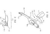
- FIG. 2is a cross-sectional view of an embodiment of a unitary component made in accordance with the present invention having a tip portion and a balloon or elongate sleeve portion;
- FIG. 3is a perspective view of an embodiment of a balloon catheter of the present invention having an uninflated balloon
- FIG. 4is a perspective view of the balloon catheter of FIG. 3 with the balloon inflated
- FIG. 4Ais an enlargement of the encircled area of FIG. 4 ;
- FIG. 5is a cross-sectional view of the balloon catheter of FIG. 3 ;
- FIG. 5Ais an enlargement of the encircled area of FIG. 5 ;
- FIG. 6is a cross-sectional view of the balloon catheter of FIG. 3 , except that FIG. 6 shows an alternative attachment unitary component to the catheter;
- FIG. 6Ais an enlargement of the encircled area of FIG. 6 ;
- FIG. 7is a cross-sectional view of the balloon catheter similar to that of FIG. 6 , except that FIG. 7 shows an alternative attachment of the distal end of the tip of the unitary component;
- FIG. 8is a cross-sectional view of the balloon catheter similar to that of FIG. 6 , except that the proximal end of the unitary component is invertedly attached to the catheter shaft.
- One embodiment of the present inventionrelates to a unitary component having a tip portion integrally formed with an expandable sleeve portion.
- the tip portion of the unitary componentmay be stiff or rigid.
- Another embodiment of the present inventionis directed to a catheter having an elongate shaft and a unitary component having a tip region integrally formed with an expandable region.
- the elongate shaftshould have a distal end, a first lumen adapted for fluid communication, an exterior, and a second lumen adapted for fluid communication with a cavity defined by the exterior of the shaft and the unitary component. It will be appreciated that the size and shape of the cavity defined by or between the exterior of the shaft and the expandable region of the unitary catheter is variable.
- distalrefers to the direction of the patient and the term “proximal” refers to the direction of the clinician.
- Yet another embodiment of the present inventionis directed to a balloon catheter having a head with at least two openings through which fluid may pass; a catheter shaft or segment extending from the head, the catheter shaft having a first and second lumen, each of the lumens being disposed in communication with at least one of the at least two openings; and a balloon formed by a sleeve at a first end of a unitary component, the first end of the unitary component being attached to the exterior of the catheter shaft so as to form a first cuff, and a second end of the unitary component having a tip portion and being attached to the distal end of the catheter shaft.
- the sleevebeing such that it will generally collapse about the catheter shaft when not inflated.
- the term expandable sleeve portionmay also mean or include, but is not limited to, a balloon, a sleeve, an elongate sleeve, an expandable sleeve, an expandable region or portion, an inflatable member, any other suitable means for expansion or the like.
- the term expandable sleeve portionwill hereinafter be referred to as a balloon.
- inflation of the balloonreference is made to inflation of the balloon, however, the present invention is not intended to be limited only to inflation. That is, while inflation is used herein for purposes of ease of reading and understanding the disclosure, the term inflation is also intended to mean or include, but is not limited to, expansion, enlargement, swelling or the like.
- tip portionis contemplated to mean or include, but is not limited to, tips of all shapes and sizes, a tip member, tip, tip region, the portion of the unitary component containing the tip, and the like.
- tip portionwill hereinafter be referred to as a tip.
- a unitary component 117having a tip 119 and a balloon 118 .
- the tip 119 of the component 117may be stiff or rigid, or at least as stiff as and/or more rigid than the balloon 118 and/or the catheter shaft 114 ( FIG. 3 ), when present, as described below.
- the unitary component 117 of FIG. 2is generally used in conjunction with a catheter such as balloon catheter 110 in FIGS. 3-8 .
- the catheter 110includes a proximal head 112 , a shaft 114 and a unitary component 117 .
- the head 112has a proximal opening 120 to a feeding lumen 122 within the shaft 114 , for bolus feeding, or providing other nutrient fluids, formula, or the like to a patient (not depicted).
- an anti-reflux valve 124which is generally included to prevent back-flow of the nutrient formula, is shown disposed between the opening 120 and the feeding lumen 122 .
- Inflation port 126is disposed in head 112 and communicates with the inflation lumen 128 which extends longitudinally through the shaft 114 .
- the inflation lumen 128terminates laterally to the shaft 114 at port 134 into the cavity 135 created by the balloon 118 of the unitary component 117 and the shaft 114 , as discussed in more detail below.
- a one-way valve 130may be disposed between the inflation port 126 and inflation lumen 128 .
- Application of positive fluid pressure, such as with air or saline, within and/or upon the inflation lumen 128 by way of the inflation port 126may cause the balloon 118 of the unitary component 117 to inflate.
- Valve 130helps prevent inadvertent deflation of the balloon 118 .
- the plug 131can be inserted in the opening 120 thereby reducing or precluding contamination when the opening 120 is not in use.
- Feeding lumen 122extends longitudinally through shaft 114 and terminates at the distal end 140 of the shaft 114 .
- balloon catheter 110may be made of any suitable material and may desirably be formed from bio-compatible materials such as medical grade silicone or the like.
- valves 124 and 130may be formed of any suitable material but are desirably made of a suitable polymer such as polycarbonate.
- the catheters and the tips of the prior deviceswere made separately and later assembled.
- Reasons for separate manufacture in the pastinclude, but are not limited to, that it was desirable in one or more instances for the tip 30 ( FIG. 1 ) to be made of a material different from that used to construct the catheter 10 ( FIG. 1 ), or if made of the same material for the tip 30 to exhibit different physical properties (e.g., as a result of different processing conditions or steps) from the catheter 10 .
- the tip 119 ( FIGS. 5-8 ) and shaft 114 of the present inventiondesirably should be able to withstand insertion pressures without binding or buckling.
- the unitary component 117 of the present inventionmay be constructed in any number of suitable manners, including, but not limited to, injection molding, transfer molding or dipping. Further, the unitary component 117 may be attached to the catheter 110 in a variety of manners, including, but not limited to, gluing or attachment during one of the injection molding, transfer molding or dipping processes referred to above. The unitary component 117 could also be attached to the catheter 110 by way of chemical bonding, such as solvent bonding. As shown in FIGS. 5 and 5A , unitary component 117 may be attached to the catheter 110 in such a way as to overlap with the distal end 140 of the catheter 110 . The overlap may be on the exterior ( FIGS. 5 and 5A ) of the catheter shaft 114 or the interior ( FIGS.
- the unitary component 117may, for example, be attached to the end 140 of the catheter shaft 114 in such a way that there is little or no overlap and such that little or no restriction of the feeding lumen 122 occurs at the point of attachment between the distal end 121 of the unitary component 117 and the distal end 140 of the catheter 110 .
- any of the manners of attachment of the unitary component 117 to the catheter shaft 114 discussed abovestill avoid the undesirable restriction of the flow associated with the prior art tips having the balloon attached to the interior of the tip (thereby reducing the size of the passageway through the tip which is available for fluid communication). Accordingly, the use of a unitary component 117 ( FIGS. 2-8 ) may enable the user to use a tip 119 ( FIGS. 5-8 ) having a smaller cross-sectional area and/or a smaller sized catheter shaft 114 as the desired level of fluid flow can be achieved in less time under the same use conditions when compared with prior devices having attachments of the balloon to the interior of the tip. It will be appreciated that there are a number advantages or benefits associated with the ability to use a catheter having a smaller shaft diameter where no adverse effects exist as a result of using the catheter with a smaller shaft diameter.
- the unitary component 117is designed such that at least a portion of the balloon 118 of the unitary component 117 may be inverted about or around all or a part of the tip 119 of the unitary component 117 .
- the composition and/or physical characteristics of the catheter 110 and the tip 119may vary, so too may the composition and/or the physical characteristics of one or more portions or regions of the unitary component 117 . That is, for example, the unitary component 117 , will have a thickness, however, the thickness, as well as the weight, shape, or density of one or more portions of the unitary component may vary. More specifically, for example, the portion of the unitary component 117 including tip 119 may have different properties (e.g., durometer, thickness, elasticity, density, etc.) from the portion of the component 117 including the balloon 118 .
- propertiese.g., durometer, thickness, elasticity, density, etc.
- the properties and/or characteristics of the componentmay vary.
- the tip 119may be tapered and/or the portion of the unitary component 117 having the balloon 118 may be more expandable or elastic in some areas than in others.
- the regions or portions of the unitary component 117are, in some instances herein, referred to separately, they are in fact part of one component, the unitary component 117 .
- the regionsmay generally be referred to as separate regions, there is in fact no hard line as to where one region or portion begins and another ends.
- transition zonewhere a part of a portion or region may exhibit the properties and/or characteristics of two regions, may be found in the unitary component 117 .
- a transition zonemay even be found within a portion of a unitary component 117 . For example, in the portion of a unitary component 117 containing a balloon 118 having different levels of elasticity, there will exist a transition zone between the areas exhibiting different levels of elasticity.
- the unitary component 117has one end 121 ( FIG. 2 ) adjacent the portion of the unitary component 117 having the tip 119 and a second end 123 adjacent the portion of the unitary component 117 having the balloon 118 .
- the end 123 of balloon 118which may be inverted about at least part of the tip 119 can be attached to the catheter shaft 114 ( FIGS. 3 , 3 A, 4 and 4 A) in a variety of suitable manners.
- the end 123may be attached to the exterior of the shaft 114 as shown in FIGS. 3 , 3 A, 4 and 4 A.
- the end 123may be attached so as to form, for example, a cuff 132 ( FIGS. 3 , 3 A, 4 and 4 A), or may be attached in an inverted fashion as shown in FIG. 8 and as discussed in commonly assigned co-pending U.S. patent application Ser. No. 10,307,057, entitled “CATHETER HAVING A BALLOON MEMBER INVERTEDLY ATTACHED THERETO”, filed in the names of Letson et al. on Nov. 30, 2002 , the disclosure of which is herein incorporated by reference in its entirety.
- the size of the catheter 110 as well as the length (inflated and uninflated) of the balloon 118may be varied in accordance with the size and shape of the body cavity (not shown) the catheter 110 is to be used in and the nature of the matter to be moved through the catheter 110 . That is, in some instances, it may be desirable to use catheters 110 having larger and/or wider shafts 114 than in other embodiments. Additionally, as discussed in more detail below the balloon 118 of the catheter 110 may be designed to have a certain size and/or shape in either or both of its inflated or uninflated configurations.
- the length of the balloon 118 as well as the point along the shaft 114 at which the end 123 of the balloon 118 is attachedmay affect the shape of the resulting balloon.
- Another suitable way of controlling the shape of the resulting inflated balloon 118includes annular rings such as those shown at 160 , 160 ′, and 160 ′′ in FIG. 2 .
- Another way of controlling the shape of the inflatable balloonincludes, but is not limited to, rotational dipping, commonly done in the condom industry in order to create a uniform film.
- Still other suitable ways of controlling the shape of the resulting ballooninclude, but are not limited to, those discussed in the U.S. Pat. No. 6,264,631 B1 to Willis et al., which is incorporated by reference in its entirety.
Landscapes
- Health & Medical Sciences (AREA)
- Heart & Thoracic Surgery (AREA)
- Life Sciences & Earth Sciences (AREA)
- General Health & Medical Sciences (AREA)
- Veterinary Medicine (AREA)
- Hematology (AREA)
- Anesthesiology (AREA)
- Animal Behavior & Ethology (AREA)
- Engineering & Computer Science (AREA)
- Public Health (AREA)
- Biomedical Technology (AREA)
- Child & Adolescent Psychology (AREA)
- Biophysics (AREA)
- Pulmonology (AREA)
- Media Introduction/Drainage Providing Device (AREA)
- Materials For Medical Uses (AREA)
- Medical Preparation Storing Or Oral Administration Devices (AREA)
Abstract
Description
Claims (4)
Priority Applications (13)
| Application Number | Priority Date | Filing Date | Title |
|---|---|---|---|
| US10/306,999US7534224B2 (en) | 2002-11-30 | 2002-11-30 | Catheter with unitary component |
| EP03779403AEP1581297B1 (en) | 2002-11-30 | 2003-10-29 | Catheter with unitary component |
| KR1020057009592AKR101116542B1 (en) | 2002-11-30 | 2003-10-29 | Catheter with unitary component |
| BRPI0316808ABRPI0316808B1 (en) | 2002-11-30 | 2003-10-29 | catheter |
| PT03779403TPT1581297E (en) | 2002-11-30 | 2003-10-29 | Catheter with unitary component |
| JP2004557151AJP4599170B2 (en) | 2002-11-30 | 2003-10-29 | Catheter with integral part |
| DK03779403.9TDK1581297T3 (en) | 2002-11-30 | 2003-10-29 | Catheter with device component |
| CA2505010ACA2505010C (en) | 2002-11-30 | 2003-10-29 | Catheter with unitary component |
| ES03779403TES2385558T3 (en) | 2002-11-30 | 2003-10-29 | Catheter with unit component |
| MXPA05005563AMXPA05005563A (en) | 2002-11-30 | 2003-10-29 | Catheter with unitary component. |
| PCT/US2003/034278WO2004050164A1 (en) | 2002-11-30 | 2003-10-29 | Catheter with unitary component |
| AU2003285087AAU2003285087B2 (en) | 2002-11-30 | 2003-10-29 | Catheter with unitary component |
| NO20052946ANO20052946L (en) | 2002-11-30 | 2005-06-16 | Catheter with device component |
Applications Claiming Priority (1)
| Application Number | Priority Date | Filing Date | Title |
|---|---|---|---|
| US10/306,999US7534224B2 (en) | 2002-11-30 | 2002-11-30 | Catheter with unitary component |
Publications (2)
| Publication Number | Publication Date |
|---|---|
| US20040106900A1 US20040106900A1 (en) | 2004-06-03 |
| US7534224B2true US7534224B2 (en) | 2009-05-19 |
Family
ID=32392504
Family Applications (1)
| Application Number | Title | Priority Date | Filing Date |
|---|---|---|---|
| US10/306,999Expired - LifetimeUS7534224B2 (en) | 2002-11-30 | 2002-11-30 | Catheter with unitary component |
Country Status (12)
| Country | Link |
|---|---|
| US (1) | US7534224B2 (en) |
| EP (1) | EP1581297B1 (en) |
| JP (1) | JP4599170B2 (en) |
| AU (1) | AU2003285087B2 (en) |
| BR (1) | BRPI0316808B1 (en) |
| CA (1) | CA2505010C (en) |
| DK (1) | DK1581297T3 (en) |
| ES (1) | ES2385558T3 (en) |
| MX (1) | MXPA05005563A (en) |
| NO (1) | NO20052946L (en) |
| PT (1) | PT1581297E (en) |
| WO (1) | WO2004050164A1 (en) |
Cited By (10)
| Publication number | Priority date | Publication date | Assignee | Title |
|---|---|---|---|---|
| US20070276356A1 (en)* | 2004-06-29 | 2007-11-29 | C. R. Bard, Inc. | Methods And Systems For Providing Fluid Communication With A Gastrostomy Tube |
| US20110028896A1 (en)* | 2005-06-06 | 2011-02-03 | C.R. Bard, Inc. | Feeding device including balloon tip and method of manufacture |
| WO2012012728A1 (en)* | 2010-07-23 | 2012-01-26 | Medela Holding Ag | Enteral feeding assembly |
| US8177742B1 (en) | 2010-12-23 | 2012-05-15 | Kimberly-Clark Wordwide, Inc. | Inflatable retention system for an enteral feeding device |
| USD679804S1 (en) | 2011-09-22 | 2013-04-09 | Vital 5, Llc | Catheter |
| US8551043B2 (en) | 2006-04-21 | 2013-10-08 | C. R. Bard, Inc. | Feeding device and bolster apparatus and method for making the same |
| US8715244B2 (en) | 2009-07-07 | 2014-05-06 | C. R. Bard, Inc. | Extensible internal bolster for a medical device |
| US9265913B2 (en) | 2010-09-22 | 2016-02-23 | Vital 5, Llc | Catheter assembly |
| US9402973B2 (en) | 2007-07-06 | 2016-08-02 | Vital 5, Llc | Constrained fluid delivery device |
| US9446224B2 (en) | 2010-09-22 | 2016-09-20 | Vital 5, L.L.C. | Barrier catheter |
Families Citing this family (21)
| Publication number | Priority date | Publication date | Assignee | Title |
|---|---|---|---|---|
| DE10131152B4 (en)* | 2001-04-30 | 2004-05-27 | Nutricia Healthcare S.A. | Medical balloon button system |
| US20050267415A1 (en)* | 2004-05-14 | 2005-12-01 | C. R. Bard, Inc. | Medical devices and methods of use |
| US20060116637A1 (en)* | 2004-11-30 | 2006-06-01 | Kimberly-Clark Worldwide, Inc. | Tract measuring device having a unitary occluded tip and inflatable sock member and method of making the same |
| US20060116658A1 (en)* | 2004-11-30 | 2006-06-01 | Kimberly-Clark Worldwide, Inc. | Multi-lumen stoma measuring device and method for using same |
| US8434487B2 (en) | 2006-06-22 | 2013-05-07 | Covidien Lp | Endotracheal cuff and technique for using the same |
| US8196584B2 (en) | 2006-06-22 | 2012-06-12 | Nellcor Puritan Bennett Llc | Endotracheal cuff and technique for using the same |
| US8684175B2 (en) | 2006-09-22 | 2014-04-01 | Covidien Lp | Method for shipping and protecting an endotracheal tube with an inflated cuff |
| US8561614B2 (en)* | 2006-09-28 | 2013-10-22 | Covidien Lp | Multi-layer cuffs for medical devices |
| US8807136B2 (en) | 2006-09-29 | 2014-08-19 | Covidien Lp | Self-sizing adjustable endotracheal tube |
| US8307830B2 (en) | 2006-09-29 | 2012-11-13 | Nellcor Puritan Bennett Llc | Endotracheal cuff and technique for using the same |
| US7950393B2 (en) | 2006-09-29 | 2011-05-31 | Nellcor Puritan Bennett Llc | Endotracheal cuff and technique for using the same |
| US20080078405A1 (en) | 2006-09-29 | 2008-04-03 | Crumback Gary L | Self-sizing adjustable endotracheal tube |
| US20080078399A1 (en) | 2006-09-29 | 2008-04-03 | O'neil Michael P | Self-sizing adjustable endotracheal tube |
| US8750978B2 (en) | 2007-12-31 | 2014-06-10 | Covidien Lp | System and sensor for early detection of shock or perfusion failure and technique for using the same |
| DE102008041286A1 (en)* | 2008-04-30 | 2009-11-05 | Carl Zeiss Surgical Gmbh | Balloon catheter and X-ray applicator with a balloon catheter |
| US8590534B2 (en) | 2009-06-22 | 2013-11-26 | Covidien Lp | Cuff for use with medical tubing and method and apparatus for making the same |
| US8636724B2 (en)* | 2009-10-26 | 2014-01-28 | Poiesis Medical, Llc | Balloon encapsulated catheter tip |
| BR112013003610A2 (en)* | 2010-08-17 | 2016-08-16 | St Jude Medical | placement system for placing and implanting a medical implant |
| AU2014393380A1 (en)* | 2014-05-05 | 2016-12-01 | Ambiente Handels-Gmbh | Feeding tube |
| JP2020151139A (en)* | 2019-03-19 | 2020-09-24 | 信越ポリマー株式会社 | Balloon catheter |
| JP7460340B2 (en)* | 2019-09-19 | 2024-04-02 | 信越ポリマー株式会社 | balloon catheter |
Citations (88)
| Publication number | Priority date | Publication date | Assignee | Title |
|---|---|---|---|---|
| US1598283A (en) | 1925-04-27 | 1926-08-31 | Justus R Kinney | Draining device |
| US3050066A (en)* | 1958-12-31 | 1962-08-21 | Wilbur R Koehn | Retention catheters |
| US3544668A (en) | 1968-07-22 | 1970-12-01 | Davol Inc | Method of manufacturing a balloon catheter |
| US3865666A (en) | 1973-05-08 | 1975-02-11 | Int Paper Co | Method of making a catheter |
| US3915171A (en) | 1974-06-06 | 1975-10-28 | Dennis William Shermeta | Gastrostomy tube |
| US3959429A (en) | 1975-02-03 | 1976-05-25 | International Paper Company | Method of making a retention catheter and molding a tip thereon |
| US4157094A (en) | 1977-09-01 | 1979-06-05 | The Kendall Company | Catheter with improved balloon and tip assembly |
| US4210478A (en) | 1973-05-08 | 1980-07-01 | International Paper Company | Method of making a catheter |
| US4213461A (en) | 1977-09-15 | 1980-07-22 | Pevsner Paul H | Miniature balloon catheter |
| US4227293A (en) | 1978-12-11 | 1980-10-14 | The Kendall Company | Method of catheter manufacture |
| US4284459A (en) | 1978-07-03 | 1981-08-18 | The Kendall Company | Method for making a molded catheter |
| US4315513A (en) | 1980-03-10 | 1982-02-16 | Nawash Michael S | Gastrostomy and other percutaneous transport tubes |
| US4393873A (en) | 1980-03-10 | 1983-07-19 | Nawash Michael S | Gastrostomy and other percutaneous transport tubes |
| US4447228A (en) | 1980-05-05 | 1984-05-08 | The Kendall Company | Catheter |
| US4531943A (en) | 1983-08-08 | 1985-07-30 | Angiomedics Corporation | Catheter with soft deformable tip |
| US4634435A (en) | 1985-08-23 | 1987-01-06 | Ingraham Steven A | Naso-gastric tube |
| US4639252A (en) | 1985-04-05 | 1987-01-27 | Research Medical, Inc. | Venous return catheter |
| US4661095A (en) | 1985-02-12 | 1987-04-28 | Becton, Dickinson And Company | Method for bonding polyurethane balloons to multilumen catheters |
| US4666433A (en) | 1984-11-05 | 1987-05-19 | Medical Innovations Corporation | Gastrostomy feeding device |
| US4685901A (en) | 1984-11-05 | 1987-08-11 | Medical Innovations Corporation | Gastro-jejunal feeding device |
| US4737219A (en) | 1985-02-12 | 1988-04-12 | Becton, Dickinson And Company | Method for bonding polyurethane balloons to multilumen catheters |
| WO1988005316A1 (en) | 1987-01-13 | 1988-07-28 | Terumo Kabushiki Kaisha | Balloon catheter and production thereof |
| US4798592A (en) | 1984-11-05 | 1989-01-17 | Medical Innovations Corporation | Gastrostomy feeding device |
| US4850953A (en) | 1987-07-27 | 1989-07-25 | Habley Medical Technology Corporation | Gastrostomy valve |
| US4874373A (en) | 1987-03-03 | 1989-10-17 | Luther Ronald B | Dip formed catheter and assembly |
| GB2218372A (en) | 1988-05-13 | 1989-11-15 | Sumitomo Rubber Ind | Moulding a multilayer spherical article |
| US4886059A (en) | 1988-06-23 | 1989-12-12 | Applied Biometrics, Incorporated | Endotracheal tube with asymmetric balloon |
| US4927412A (en)* | 1988-12-08 | 1990-05-22 | Retroperfusion Systems, Inc. | Coronary sinus catheter |
| US4950239A (en) | 1988-08-09 | 1990-08-21 | Worldwide Medical Plastics Inc. | Angioplasty balloons and balloon catheters |
| US4976710A (en) | 1987-01-28 | 1990-12-11 | Mackin Robert A | Working well balloon method |
| CA2019886A1 (en) | 1989-07-18 | 1991-01-18 | Manouchehr Miraki | Catheter with heat-fused balloon with waist |
| US5009639A (en) | 1987-04-23 | 1991-04-23 | Fresenius, Ag | Gastric/duodenal/jejunal catheter for percutaneous enternal feeding |
| US5074845A (en) | 1989-07-18 | 1991-12-24 | Baxter International Inc. | Catheter with heat-fused balloon with waist |
| US5080650A (en) | 1991-01-28 | 1992-01-14 | Abbott Laboratories | Gastrostomy tube |
| US5087394A (en) | 1989-11-09 | 1992-02-11 | Scimed Life Systems, Inc. | Method for forming an inflatable balloon for use in a catheter |
| US5125897A (en) | 1990-04-27 | 1992-06-30 | Corpak, Inc. | Gastrostomy device with one-way valve and cuff pin |
| US5137671A (en) | 1990-01-10 | 1992-08-11 | Rochester Medical Corporation | Methods of making balloon catheters |
| US5156612A (en) | 1988-10-04 | 1992-10-20 | Cordis Corporation | Balloons for medical devices and fabrication thereof |
| US5160321A (en)* | 1988-11-23 | 1992-11-03 | Harvinder Sahota | Balloon catheters |
| DE9208103U1 (en) | 1992-06-17 | 1993-03-04 | B. Braun Melsungen Ag, 3508 Melsungen | Puncture device |
| US5195969A (en) | 1991-04-26 | 1993-03-23 | Boston Scientific Corporation | Co-extruded medical balloons and catheter using such balloons |
| US5250040A (en) | 1989-12-21 | 1993-10-05 | Medical Innovations Corporation | Ferrule and enteral tube incorporating a ferrule |
| US5267969A (en) | 1992-10-08 | 1993-12-07 | Abbott Laboratories | External retaining device for feeding tube or the like |
| US5295969A (en) | 1992-04-27 | 1994-03-22 | Cathco, Inc. | Vascular access device with air-tight blood containment capability |
| US5308325A (en)* | 1991-01-28 | 1994-05-03 | Corpak, Inc. | Retention balloon for percutaneous catheter |
| US5324260A (en)* | 1992-04-27 | 1994-06-28 | Minnesota Mining And Manufacturing Company | Retrograde coronary sinus catheter |
| US5370899A (en) | 1990-01-10 | 1994-12-06 | Conway; Anthony J. | Catheter having lubricated outer sleeve and method for making same |
| US5370618A (en) | 1992-11-20 | 1994-12-06 | World Medical Manufacturing Corporation | Pulmonary artery polyurethane balloon catheter |
| US5391159A (en) | 1994-02-04 | 1995-02-21 | Hirsch; William H. | Gastrostomy tube with improved internal retaining member |
| US5411477A (en) | 1990-05-11 | 1995-05-02 | Saab; Mark A. | High-strength, thin-walled single piece catheters |
| US5423760A (en)* | 1991-12-06 | 1995-06-13 | Yoon; Inbae | Automatic retractable safety penetrating instrument |
| US5439444A (en) | 1991-01-28 | 1995-08-08 | Corpak, Inc. | Pre-formed member for percutaneous catheter |
| US5458583A (en) | 1993-01-07 | 1995-10-17 | Medical Innovations Corporation | Gastrostomy catheter system |
| US5514153A (en) | 1990-03-02 | 1996-05-07 | General Surgical Innovations, Inc. | Method of dissecting tissue layers |
| US5527280A (en) | 1995-03-29 | 1996-06-18 | The Children's Seashore House | Multi-lumen enteral feeding and medicating device |
| US5593718A (en) | 1990-01-10 | 1997-01-14 | Rochester Medical Corporation | Method of making catheter |
| US5707357A (en) | 1995-02-23 | 1998-01-13 | C V Dynamics, Inc. | Balloon catheter having palpitatable discharge valve and retention collar |
| US5709691A (en)* | 1996-03-11 | 1998-01-20 | Morejon; Orlando | Endotracheal tube cleaning device |
| US5718861A (en) | 1993-12-20 | 1998-02-17 | C. R. Bard, Incorporated | Method of forming intra-aortic balloon catheters |
| US5718712A (en) | 1994-08-10 | 1998-02-17 | Elekta Ab | Dilatation balloon catheter for endoscopy |
| US5762996A (en) | 1996-04-15 | 1998-06-09 | Lucas; Daniel R. | Silicone balloon catheter |
| US5792118A (en) | 1994-03-07 | 1998-08-11 | Kurth; Paul A. | Permanent catheter with an exterior balloon valve and method of using the same |
| US5807520A (en) | 1995-11-08 | 1998-09-15 | Scimed Life Systems, Inc. | Method of balloon formation by cold drawing/necking |
| US5836924A (en)* | 1997-01-02 | 1998-11-17 | Mri Manufacturing And Research, Inc. | Feeding tube apparatus with rotational on/off valve |
| US5860960A (en) | 1996-01-11 | 1999-01-19 | C. R. Bard, Inc. | Bolster for corporeal access tube assembly |
| US5860952A (en) | 1996-01-11 | 1999-01-19 | C. R. Bard, Inc. | Corporeal access tube assembly and method |
| US5879499A (en)* | 1996-06-17 | 1999-03-09 | Heartport, Inc. | Method of manufacture of a multi-lumen catheter |
| US5938585A (en) | 1998-03-20 | 1999-08-17 | Boston Scientific Corporation | Anchoring and positioning device and method for an endoscope |
| EP0943354A1 (en) | 1998-03-17 | 1999-09-22 | Medtronic, Inc. | Balloon attachment at catheter tip |
| US5971954A (en) | 1990-01-10 | 1999-10-26 | Rochester Medical Corporation | Method of making catheter |
| US5997546A (en)* | 1999-01-07 | 1999-12-07 | Ballard Medical Products | Gastric balloon catheter with improved balloon orientation |
| US5997503A (en) | 1998-02-12 | 1999-12-07 | Ballard Medical Products | Catheter with distally distending balloon |
| US6013054A (en) | 1997-04-28 | 2000-01-11 | Advanced Cardiovascular Systems, Inc. | Multifurcated balloon catheter |
| CA2347208A1 (en) | 1998-10-19 | 2000-04-27 | C.R. Bard, Inc. | Retention balloon for a corporeal access tube assembly |
| US6129713A (en)* | 1998-08-11 | 2000-10-10 | Embol-X, Inc. | Slidable cannula and method of use |
| US6248121B1 (en) | 1998-02-18 | 2001-06-19 | Cardio Medical Solutions, Inc. | Blood vessel occlusion device |
| US20010035590A1 (en) | 1998-07-30 | 2001-11-01 | Hiroyuki Nishi | Transfer molding apparatus and method for manufacturing semiconductor devices |
| US6328720B1 (en) | 2000-02-18 | 2001-12-11 | Zevex, Inc. | Low-profile enterostomy device |
| WO2002022198A2 (en) | 2000-09-14 | 2002-03-21 | Tuborg Engineering Nv | Adaptive balloon with improved flexibility |
| WO2002051490A1 (en) | 2000-12-22 | 2002-07-04 | Khalid Al-Saadon | Balloon for a balloon dilation catheter and stent implantation |
| US6447472B1 (en) | 2000-10-19 | 2002-09-10 | Gerald Moss | Method and pump apparatus for combined gastro-intestinal feeding and aspiration |
| WO2002087492A1 (en) | 2001-04-30 | 2002-11-07 | Nutricia Healthcare S.A. | Button-balloon system |
| US20020198440A1 (en) | 2001-06-20 | 2002-12-26 | Todd Snow | Temporary dilating tip for gastro-intestinal tubes |
| US20020198491A1 (en) | 2001-06-26 | 2002-12-26 | John Miller | Large lumen balloon catheter |
| US6506179B1 (en)* | 2001-10-12 | 2003-01-14 | Abbott Laboratories | Tube having a retention member |
| US6524283B1 (en)* | 1994-10-07 | 2003-02-25 | Sherwood Services Ag | Method and apparatus for anchoring laparoscopic instruments |
| US20030225369A1 (en) | 2002-05-31 | 2003-12-04 | Kimberly-Clark Worldwide, Inc. | Low profile transpyloric jejunostomy system |
| US6740273B2 (en) | 2001-01-03 | 2004-05-25 | Keun-Ho Lee | Method for making balloon catheter |
Family Cites Families (4)
| Publication number | Priority date | Publication date | Assignee | Title |
|---|---|---|---|---|
| US91365A (en)* | 1869-06-15 | Improvement in apparatus for destroying worms on cotton-plants | ||
| US198440A (en)* | 1877-12-18 | Improvement in flock-cutting machines | ||
| JPS642661A (en)* | 1987-06-25 | 1989-01-06 | Terumo Corp | Preparation of balloon catheter |
| JPH07313602A (en)* | 1994-05-24 | 1995-12-05 | Nippon Zeon Co Ltd | Sliding catheter |
- 2002
- 2002-11-30USUS10/306,999patent/US7534224B2/ennot_activeExpired - Lifetime
- 2003
- 2003-10-29WOPCT/US2003/034278patent/WO2004050164A1/enactiveApplication Filing
- 2003-10-29EPEP03779403Apatent/EP1581297B1/ennot_activeExpired - Lifetime
- 2003-10-29AUAU2003285087Apatent/AU2003285087B2/ennot_activeCeased
- 2003-10-29BRBRPI0316808Apatent/BRPI0316808B1/ennot_activeIP Right Cessation
- 2003-10-29CACA2505010Apatent/CA2505010C/ennot_activeExpired - Fee Related
- 2003-10-29DKDK03779403.9Tpatent/DK1581297T3/enactive
- 2003-10-29ESES03779403Tpatent/ES2385558T3/ennot_activeExpired - Lifetime
- 2003-10-29MXMXPA05005563Apatent/MXPA05005563A/enactiveIP Right Grant
- 2003-10-29PTPT03779403Tpatent/PT1581297E/enunknown
- 2003-10-29JPJP2004557151Apatent/JP4599170B2/ennot_activeExpired - Lifetime
- 2005
- 2005-06-16NONO20052946Apatent/NO20052946L/enunknown
Patent Citations (107)
| Publication number | Priority date | Publication date | Assignee | Title |
|---|---|---|---|---|
| US1598283A (en) | 1925-04-27 | 1926-08-31 | Justus R Kinney | Draining device |
| US3050066A (en)* | 1958-12-31 | 1962-08-21 | Wilbur R Koehn | Retention catheters |
| US3544668A (en) | 1968-07-22 | 1970-12-01 | Davol Inc | Method of manufacturing a balloon catheter |
| US4210478A (en) | 1973-05-08 | 1980-07-01 | International Paper Company | Method of making a catheter |
| US3865666A (en) | 1973-05-08 | 1975-02-11 | Int Paper Co | Method of making a catheter |
| US3915171A (en) | 1974-06-06 | 1975-10-28 | Dennis William Shermeta | Gastrostomy tube |
| US3959429A (en) | 1975-02-03 | 1976-05-25 | International Paper Company | Method of making a retention catheter and molding a tip thereon |
| US4157094A (en) | 1977-09-01 | 1979-06-05 | The Kendall Company | Catheter with improved balloon and tip assembly |
| US4213461A (en) | 1977-09-15 | 1980-07-22 | Pevsner Paul H | Miniature balloon catheter |
| US4284459A (en) | 1978-07-03 | 1981-08-18 | The Kendall Company | Method for making a molded catheter |
| US4227293A (en) | 1978-12-11 | 1980-10-14 | The Kendall Company | Method of catheter manufacture |
| US4315513A (en) | 1980-03-10 | 1982-02-16 | Nawash Michael S | Gastrostomy and other percutaneous transport tubes |
| US4393873A (en) | 1980-03-10 | 1983-07-19 | Nawash Michael S | Gastrostomy and other percutaneous transport tubes |
| US4447228A (en) | 1980-05-05 | 1984-05-08 | The Kendall Company | Catheter |
| US4531943A (en) | 1983-08-08 | 1985-07-30 | Angiomedics Corporation | Catheter with soft deformable tip |
| US4798592A (en) | 1984-11-05 | 1989-01-17 | Medical Innovations Corporation | Gastrostomy feeding device |
| US4666433A (en) | 1984-11-05 | 1987-05-19 | Medical Innovations Corporation | Gastrostomy feeding device |
| US4685901A (en) | 1984-11-05 | 1987-08-11 | Medical Innovations Corporation | Gastro-jejunal feeding device |
| US4737219A (en) | 1985-02-12 | 1988-04-12 | Becton, Dickinson And Company | Method for bonding polyurethane balloons to multilumen catheters |
| US4661095A (en) | 1985-02-12 | 1987-04-28 | Becton, Dickinson And Company | Method for bonding polyurethane balloons to multilumen catheters |
| US4639252A (en) | 1985-04-05 | 1987-01-27 | Research Medical, Inc. | Venous return catheter |
| US4634435A (en) | 1985-08-23 | 1987-01-06 | Ingraham Steven A | Naso-gastric tube |
| WO1988005316A1 (en) | 1987-01-13 | 1988-07-28 | Terumo Kabushiki Kaisha | Balloon catheter and production thereof |
| EP0347458B1 (en) | 1987-01-13 | 1994-03-30 | Terumo Kabushiki Kaisha | Balloon catheter and production thereof |
| CA1299954C (en) | 1987-01-13 | 1992-05-05 | Yoshio Ishitsu | Balloon catheter and method of manufacturing the same |
| US5042976A (en) | 1987-01-13 | 1991-08-27 | Terumo Kabushiki Kaisha | Balloon catheter and manufacturing method of the same |
| US4976710A (en) | 1987-01-28 | 1990-12-11 | Mackin Robert A | Working well balloon method |
| US4874373A (en) | 1987-03-03 | 1989-10-17 | Luther Ronald B | Dip formed catheter and assembly |
| US5009639A (en) | 1987-04-23 | 1991-04-23 | Fresenius, Ag | Gastric/duodenal/jejunal catheter for percutaneous enternal feeding |
| US4850953A (en) | 1987-07-27 | 1989-07-25 | Habley Medical Technology Corporation | Gastrostomy valve |
| GB2218372A (en) | 1988-05-13 | 1989-11-15 | Sumitomo Rubber Ind | Moulding a multilayer spherical article |
| US5076268A (en) | 1988-06-23 | 1991-12-31 | Applied Biometrics Incorporated | Asymmetric balloon for endotracheal tube |
| US4886059A (en) | 1988-06-23 | 1989-12-12 | Applied Biometrics, Incorporated | Endotracheal tube with asymmetric balloon |
| US4950239A (en) | 1988-08-09 | 1990-08-21 | Worldwide Medical Plastics Inc. | Angioplasty balloons and balloon catheters |
| US5156612A (en) | 1988-10-04 | 1992-10-20 | Cordis Corporation | Balloons for medical devices and fabrication thereof |
| US5160321A (en)* | 1988-11-23 | 1992-11-03 | Harvinder Sahota | Balloon catheters |
| US4927412A (en)* | 1988-12-08 | 1990-05-22 | Retroperfusion Systems, Inc. | Coronary sinus catheter |
| EP0409436B1 (en) | 1989-07-18 | 1994-12-21 | Baxter International Inc. | Catheter with heat-fused balloon with waist |
| US5074845A (en) | 1989-07-18 | 1991-12-24 | Baxter International Inc. | Catheter with heat-fused balloon with waist |
| CA2019886A1 (en) | 1989-07-18 | 1991-01-18 | Manouchehr Miraki | Catheter with heat-fused balloon with waist |
| US5087394A (en) | 1989-11-09 | 1992-02-11 | Scimed Life Systems, Inc. | Method for forming an inflatable balloon for use in a catheter |
| US5250040A (en) | 1989-12-21 | 1993-10-05 | Medical Innovations Corporation | Ferrule and enteral tube incorporating a ferrule |
| US5137671A (en) | 1990-01-10 | 1992-08-11 | Rochester Medical Corporation | Methods of making balloon catheters |
| US5971954A (en) | 1990-01-10 | 1999-10-26 | Rochester Medical Corporation | Method of making catheter |
| US5593718A (en) | 1990-01-10 | 1997-01-14 | Rochester Medical Corporation | Method of making catheter |
| US5370899A (en) | 1990-01-10 | 1994-12-06 | Conway; Anthony J. | Catheter having lubricated outer sleeve and method for making same |
| US5514153A (en) | 1990-03-02 | 1996-05-07 | General Surgical Innovations, Inc. | Method of dissecting tissue layers |
| US5125897A (en) | 1990-04-27 | 1992-06-30 | Corpak, Inc. | Gastrostomy device with one-way valve and cuff pin |
| US5411477A (en) | 1990-05-11 | 1995-05-02 | Saab; Mark A. | High-strength, thin-walled single piece catheters |
| US5439444A (en) | 1991-01-28 | 1995-08-08 | Corpak, Inc. | Pre-formed member for percutaneous catheter |
| US5308325A (en)* | 1991-01-28 | 1994-05-03 | Corpak, Inc. | Retention balloon for percutaneous catheter |
| US5080650A (en) | 1991-01-28 | 1992-01-14 | Abbott Laboratories | Gastrostomy tube |
| US5195969A (en) | 1991-04-26 | 1993-03-23 | Boston Scientific Corporation | Co-extruded medical balloons and catheter using such balloons |
| US6136258A (en) | 1991-04-26 | 2000-10-24 | Boston Scientific Corporation | Method of forming a co-extruded balloon for medical purposes |
| US5423760A (en)* | 1991-12-06 | 1995-06-13 | Yoon; Inbae | Automatic retractable safety penetrating instrument |
| US5324260A (en)* | 1992-04-27 | 1994-06-28 | Minnesota Mining And Manufacturing Company | Retrograde coronary sinus catheter |
| US5295969A (en) | 1992-04-27 | 1994-03-22 | Cathco, Inc. | Vascular access device with air-tight blood containment capability |
| DE9208103U1 (en) | 1992-06-17 | 1993-03-04 | B. Braun Melsungen Ag, 3508 Melsungen | Puncture device |
| US5267969A (en) | 1992-10-08 | 1993-12-07 | Abbott Laboratories | External retaining device for feeding tube or the like |
| US5370618A (en) | 1992-11-20 | 1994-12-06 | World Medical Manufacturing Corporation | Pulmonary artery polyurethane balloon catheter |
| US5522961A (en) | 1992-11-20 | 1996-06-04 | World Medical Corporation | Method of construction of a balloon catheter |
| US5458583A (en) | 1993-01-07 | 1995-10-17 | Medical Innovations Corporation | Gastrostomy catheter system |
| US5865721A (en) | 1993-12-20 | 1999-02-02 | C. R. Bard, Inc. | Intra-aortic balloon catheters |
| US5718861A (en) | 1993-12-20 | 1998-02-17 | C. R. Bard, Incorporated | Method of forming intra-aortic balloon catheters |
| US5391159A (en) | 1994-02-04 | 1995-02-21 | Hirsch; William H. | Gastrostomy tube with improved internal retaining member |
| US5792118A (en) | 1994-03-07 | 1998-08-11 | Kurth; Paul A. | Permanent catheter with an exterior balloon valve and method of using the same |
| US5718712A (en) | 1994-08-10 | 1998-02-17 | Elekta Ab | Dilatation balloon catheter for endoscopy |
| US6524283B1 (en)* | 1994-10-07 | 2003-02-25 | Sherwood Services Ag | Method and apparatus for anchoring laparoscopic instruments |
| US5707357A (en) | 1995-02-23 | 1998-01-13 | C V Dynamics, Inc. | Balloon catheter having palpitatable discharge valve and retention collar |
| US6168748B1 (en) | 1995-03-02 | 2001-01-02 | Scimed Life Systems, Inc. | Method of balloon formation by cold drawing/necking |
| US5527280A (en) | 1995-03-29 | 1996-06-18 | The Children's Seashore House | Multi-lumen enteral feeding and medicating device |
| US5807520A (en) | 1995-11-08 | 1998-09-15 | Scimed Life Systems, Inc. | Method of balloon formation by cold drawing/necking |
| US5860960A (en) | 1996-01-11 | 1999-01-19 | C. R. Bard, Inc. | Bolster for corporeal access tube assembly |
| US5865816A (en) | 1996-01-11 | 1999-02-02 | C. R. Bard, Inc. | Percutaneous endoscopic gastrostomy tube assembly and method |
| US5891113A (en) | 1996-01-11 | 1999-04-06 | C. R. Bard, Inc. | Corporeal access tube assembly |
| US5910128A (en) | 1996-01-11 | 1999-06-08 | C. R. Bard, Inc. | Retention balloon and corporeal access tube assembly |
| US5860952A (en) | 1996-01-11 | 1999-01-19 | C. R. Bard, Inc. | Corporeal access tube assembly and method |
| US6077243A (en) | 1996-01-11 | 2000-06-20 | C.R. Bard, Inc. | Retention balloon for a corporeal access tube assembly |
| US5709691A (en)* | 1996-03-11 | 1998-01-20 | Morejon; Orlando | Endotracheal tube cleaning device |
| US5762996A (en) | 1996-04-15 | 1998-06-09 | Lucas; Daniel R. | Silicone balloon catheter |
| US5879499A (en)* | 1996-06-17 | 1999-03-09 | Heartport, Inc. | Method of manufacture of a multi-lumen catheter |
| US5836924A (en)* | 1997-01-02 | 1998-11-17 | Mri Manufacturing And Research, Inc. | Feeding tube apparatus with rotational on/off valve |
| US6013054A (en) | 1997-04-28 | 2000-01-11 | Advanced Cardiovascular Systems, Inc. | Multifurcated balloon catheter |
| US6287277B1 (en) | 1997-04-28 | 2001-09-11 | Advanced Cardiovascular Systems, Inc. | Balloon formation by vacuum deposition |
| US5997503A (en) | 1998-02-12 | 1999-12-07 | Ballard Medical Products | Catheter with distally distending balloon |
| US6264631B1 (en)* | 1998-02-12 | 2001-07-24 | Ballard Medical Products | Catheter with distally distending balloon |
| US6248121B1 (en) | 1998-02-18 | 2001-06-19 | Cardio Medical Solutions, Inc. | Blood vessel occlusion device |
| EP0943354A1 (en) | 1998-03-17 | 1999-09-22 | Medtronic, Inc. | Balloon attachment at catheter tip |
| US5938585A (en) | 1998-03-20 | 1999-08-17 | Boston Scientific Corporation | Anchoring and positioning device and method for an endoscope |
| US20010035590A1 (en) | 1998-07-30 | 2001-11-01 | Hiroyuki Nishi | Transfer molding apparatus and method for manufacturing semiconductor devices |
| US6129713A (en)* | 1998-08-11 | 2000-10-10 | Embol-X, Inc. | Slidable cannula and method of use |
| WO2000023136A1 (en) | 1998-10-19 | 2000-04-27 | C.R. Bard, Inc. | Retention balloon for a corporeal access tube assembly |
| CA2347208A1 (en) | 1998-10-19 | 2000-04-27 | C.R. Bard, Inc. | Retention balloon for a corporeal access tube assembly |
| US5997546A (en)* | 1999-01-07 | 1999-12-07 | Ballard Medical Products | Gastric balloon catheter with improved balloon orientation |
| WO2000040289A2 (en) | 1999-01-07 | 2000-07-13 | Ballard Medical Products | Gastric balloon catheter with improved balloon orientation |
| US20020091365A1 (en) | 2000-02-18 | 2002-07-11 | Mcnally David J. | Low-profile enterostomy device |
| US6328720B1 (en) | 2000-02-18 | 2001-12-11 | Zevex, Inc. | Low-profile enterostomy device |
| WO2002022198A2 (en) | 2000-09-14 | 2002-03-21 | Tuborg Engineering Nv | Adaptive balloon with improved flexibility |
| US6447472B1 (en) | 2000-10-19 | 2002-09-10 | Gerald Moss | Method and pump apparatus for combined gastro-intestinal feeding and aspiration |
| WO2002051490A1 (en) | 2000-12-22 | 2002-07-04 | Khalid Al-Saadon | Balloon for a balloon dilation catheter and stent implantation |
| US6740273B2 (en) | 2001-01-03 | 2004-05-25 | Keun-Ho Lee | Method for making balloon catheter |
| WO2002087492A1 (en) | 2001-04-30 | 2002-11-07 | Nutricia Healthcare S.A. | Button-balloon system |
| US20020198440A1 (en) | 2001-06-20 | 2002-12-26 | Todd Snow | Temporary dilating tip for gastro-intestinal tubes |
| US20020198491A1 (en) | 2001-06-26 | 2002-12-26 | John Miller | Large lumen balloon catheter |
| US6506179B1 (en)* | 2001-10-12 | 2003-01-14 | Abbott Laboratories | Tube having a retention member |
| WO2003032892A2 (en) | 2001-10-12 | 2003-04-24 | Abbott Laboratories | Tube having a retention member |
| US20030225369A1 (en) | 2002-05-31 | 2003-12-04 | Kimberly-Clark Worldwide, Inc. | Low profile transpyloric jejunostomy system |
Non-Patent Citations (4)
| Title |
|---|
| "PEG Percutaneous Endoscopic Gastrostomy", Brochure, one page, Create Medic Co., Ltd, 2002. |
| "Replacement Catheter", Japanese Brochure, one page, 2003. |
| Patent Abstracts of Japan, Publication No. 03277374 A, Dec. 9, 1991. |
| Patent Abstracts of Japan, Publication No. 2000254221, Sep. 19, 2000. |
Cited By (20)
| Publication number | Priority date | Publication date | Assignee | Title |
|---|---|---|---|---|
| US20070276356A1 (en)* | 2004-06-29 | 2007-11-29 | C. R. Bard, Inc. | Methods And Systems For Providing Fluid Communication With A Gastrostomy Tube |
| US8858533B2 (en) | 2004-06-29 | 2014-10-14 | C. R. Bard, Inc. | Methods and systems for providing fluid communication with a gastrostomy tube |
| US9682224B2 (en) | 2004-06-29 | 2017-06-20 | C. R. Bard, Inc. | Method and systems for providing fluid communication with a gastrostomy tube |
| US20110028896A1 (en)* | 2005-06-06 | 2011-02-03 | C.R. Bard, Inc. | Feeding device including balloon tip and method of manufacture |
| US8206347B2 (en) | 2005-06-06 | 2012-06-26 | C. R. Bard, Inc. | Feeding device including balloon tip and method of manufacture |
| US8551043B2 (en) | 2006-04-21 | 2013-10-08 | C. R. Bard, Inc. | Feeding device and bolster apparatus and method for making the same |
| US9402973B2 (en) | 2007-07-06 | 2016-08-02 | Vital 5, Llc | Constrained fluid delivery device |
| US8715244B2 (en) | 2009-07-07 | 2014-05-06 | C. R. Bard, Inc. | Extensible internal bolster for a medical device |
| US9572751B2 (en) | 2009-07-07 | 2017-02-21 | C. R. Bard, Inc. | Extensible internal bolster for a medical device |
| US10149963B2 (en) | 2010-05-11 | 2018-12-11 | Vital 5, Llc | Catheter assembly |
| CN103124581A (en)* | 2010-07-23 | 2013-05-29 | 梅德拉控股公司 | Enteral feeding assembly |
| US10004889B2 (en) | 2010-07-23 | 2018-06-26 | Medela Holding Ag | Enteral feeding connector and assembly |
| WO2012012728A1 (en)* | 2010-07-23 | 2012-01-26 | Medela Holding Ag | Enteral feeding assembly |
| US9446224B2 (en) | 2010-09-22 | 2016-09-20 | Vital 5, L.L.C. | Barrier catheter |
| US9265913B2 (en) | 2010-09-22 | 2016-02-23 | Vital 5, Llc | Catheter assembly |
| US9155684B2 (en) | 2010-12-23 | 2015-10-13 | Avent, Inc. | Inflatable retention system for an enteral feeding device |
| US9149415B2 (en) | 2010-12-23 | 2015-10-06 | Avent, Inc. | Inflatable retention system for an enteral feeding device |
| US8475406B2 (en) | 2010-12-23 | 2013-07-02 | Kimberly-Clark Worldwide, Inc. | Inflatable retention system for enteral feeding device |
| US8177742B1 (en) | 2010-12-23 | 2012-05-15 | Kimberly-Clark Wordwide, Inc. | Inflatable retention system for an enteral feeding device |
| USD679804S1 (en) | 2011-09-22 | 2013-04-09 | Vital 5, Llc | Catheter |
Also Published As
| Publication number | Publication date |
|---|---|
| MXPA05005563A (en) | 2005-10-18 |
| BR0316808A (en) | 2005-10-18 |
| BRPI0316808B1 (en) | 2015-10-27 |
| WO2004050164A1 (en) | 2004-06-17 |
| JP4599170B2 (en) | 2010-12-15 |
| JP2006507893A (en) | 2006-03-09 |
| PT1581297E (en) | 2012-08-24 |
| EP1581297A1 (en) | 2005-10-05 |
| EP1581297B1 (en) | 2012-07-04 |
| CA2505010C (en) | 2012-04-24 |
| ES2385558T3 (en) | 2012-07-26 |
| US20040106900A1 (en) | 2004-06-03 |
| DK1581297T3 (en) | 2012-09-03 |
| AU2003285087B2 (en) | 2009-04-23 |
| CA2505010A1 (en) | 2004-06-17 |
| AU2003285087A1 (en) | 2004-06-23 |
| NO20052946L (en) | 2005-06-16 |
Similar Documents
| Publication | Publication Date | Title |
|---|---|---|
| US7534224B2 (en) | Catheter with unitary component | |
| US20040106899A1 (en) | Gastric balloon catheter with improved balloon orientation | |
| EP1140272B1 (en) | Gastric balloon catheter with improved balloon orientation | |
| US6916307B2 (en) | Catheter with distally distending balloon | |
| US20040106901A1 (en) | Catheter having a balloon member invertedly attached thereto | |
| JP3683812B2 (en) | Retention balloon for body access tube assembly | |
| US20050038381A1 (en) | Catheter having a balloon member recessedly attached thereto | |
| US7124489B2 (en) | Process for producing a catheter | |
| US20040103987A1 (en) | Process for producing unitary component and a catheter having a unitary component | |
| KR101116542B1 (en) | Catheter with unitary component |
Legal Events
| Date | Code | Title | Description |
|---|---|---|---|
| AS | Assignment | Owner name:KIMBERLY-CLARK WORLDWIDE, INC., WISCONSIN Free format text:ASSIGNMENT OF ASSIGNORS INTEREST;ASSIGNORS:TRIEBES, THOMAS G.;KENOWSKI, MICHAEL A.;MCMICHAEL, DONALD J.;REEL/FRAME:015850/0049;SIGNING DATES FROM 20021203 TO 20021220 | |
| STCF | Information on status: patent grant | Free format text:PATENTED CASE | |
| FPAY | Fee payment | Year of fee payment:4 | |
| AS | Assignment | Owner name:AVENT, INC., GEORGIA Free format text:ASSIGNMENT OF ASSIGNORS INTEREST;ASSIGNOR:KIMBERLY-CLARK WORLDWIDE, INC.;REEL/FRAME:034754/0424 Effective date:20141030 | |
| AS | Assignment | Owner name:MORGAN STANLEY SENIOR FUNDING, INC., NEW YORK Free format text:SECURITY INTEREST;ASSIGNOR:AVENT, INC.;REEL/FRAME:035375/0867 Effective date:20150227 | |
| FPAY | Fee payment | Year of fee payment:8 | |
| AS | Assignment | Owner name:CITIBANK, N.A., NEW YORK Free format text:INTELLECTUAL PROPERTY SECURITY INTEREST ASSIGNMENT AGREEMENT;ASSIGNOR:MORGAN STANLEY SENIOR FUNDING, INC.;REEL/FRAME:048173/0137 Effective date:20181029 | |
| MAFP | Maintenance fee payment | Free format text:PAYMENT OF MAINTENANCE FEE, 12TH YEAR, LARGE ENTITY (ORIGINAL EVENT CODE: M1553); ENTITY STATUS OF PATENT OWNER: LARGE ENTITY Year of fee payment:12 | |
| AS | Assignment | Owner name:JPMORGAN CHASE BANK, N.A., AS ADMINISTRATIVE AGENT, ILLINOIS Free format text:SECURITY INTEREST;ASSIGNOR:AVENT, INC.;REEL/FRAME:060441/0445 Effective date:20220624 | |
| AS | Assignment | Owner name:AVANOS MEDICAL SALES, LLC, GEORGIA Free format text:RELEASE BY SECURED PARTY;ASSIGNOR:CITIBANK, N.A.;REEL/FRAME:060557/0062 Effective date:20220624 Owner name:AVENT, INC., GEORGIA Free format text:RELEASE BY SECURED PARTY;ASSIGNOR:CITIBANK, N.A.;REEL/FRAME:060557/0062 Effective date:20220624 |