US7534050B2 - Field terminatable fiber optic connector assembly - Google Patents
Field terminatable fiber optic connector assemblyDownload PDFInfo
- Publication number
- US7534050B2 US7534050B2US11/735,267US73526707AUS7534050B2US 7534050 B2US7534050 B2US 7534050B2US 73526707 AUS73526707 AUS 73526707AUS 7534050 B2US7534050 B2US 7534050B2
- Authority
- US
- United States
- Prior art keywords
- region
- disposed
- fiber optic
- optic connector
- connector
- Prior art date
- Legal status (The legal status is an assumption and is not a legal conclusion. Google has not performed a legal analysis and makes no representation as to the accuracy of the status listed.)
- Expired - Fee Related
Links
Images


Classifications
- G—PHYSICS
- G02—OPTICS
- G02B—OPTICAL ELEMENTS, SYSTEMS OR APPARATUS
- G02B6/00—Light guides; Structural details of arrangements comprising light guides and other optical elements, e.g. couplings
- G02B6/24—Coupling light guides
- G02B6/36—Mechanical coupling means
- G02B6/38—Mechanical coupling means having fibre to fibre mating means
- G02B6/3807—Dismountable connectors, i.e. comprising plugs
- G02B6/3887—Anchoring optical cables to connector housings, e.g. strain relief features
- G02B6/3888—Protection from over-extension or over-compression
- G—PHYSICS
- G02—OPTICS
- G02B—OPTICAL ELEMENTS, SYSTEMS OR APPARATUS
- G02B6/00—Light guides; Structural details of arrangements comprising light guides and other optical elements, e.g. couplings
- G02B6/24—Coupling light guides
- G02B6/36—Mechanical coupling means
- G02B6/38—Mechanical coupling means having fibre to fibre mating means
- G02B6/3801—Permanent connections, i.e. wherein fibres are kept aligned by mechanical means
- G02B6/3806—Semi-permanent connections, i.e. wherein the mechanical means keeping the fibres aligned allow for removal of the fibres
- G—PHYSICS
- G02—OPTICS
- G02B—OPTICAL ELEMENTS, SYSTEMS OR APPARATUS
- G02B6/00—Light guides; Structural details of arrangements comprising light guides and other optical elements, e.g. couplings
- G02B6/24—Coupling light guides
- G02B6/36—Mechanical coupling means
- G02B6/38—Mechanical coupling means having fibre to fibre mating means
- G02B6/3807—Dismountable connectors, i.e. comprising plugs
- G02B6/381—Dismountable connectors, i.e. comprising plugs of the ferrule type, e.g. fibre ends embedded in ferrules, connecting a pair of fibres
- G02B6/3818—Dismountable connectors, i.e. comprising plugs of the ferrule type, e.g. fibre ends embedded in ferrules, connecting a pair of fibres of a low-reflection-loss type
- G02B6/3821—Dismountable connectors, i.e. comprising plugs of the ferrule type, e.g. fibre ends embedded in ferrules, connecting a pair of fibres of a low-reflection-loss type with axial spring biasing or loading means
- G—PHYSICS
- G02—OPTICS
- G02B—OPTICAL ELEMENTS, SYSTEMS OR APPARATUS
- G02B6/00—Light guides; Structural details of arrangements comprising light guides and other optical elements, e.g. couplings
- G02B6/24—Coupling light guides
- G02B6/36—Mechanical coupling means
- G02B6/38—Mechanical coupling means having fibre to fibre mating means
- G02B6/3807—Dismountable connectors, i.e. comprising plugs
- G02B6/381—Dismountable connectors, i.e. comprising plugs of the ferrule type, e.g. fibre ends embedded in ferrules, connecting a pair of fibres
- G02B6/3825—Dismountable connectors, i.e. comprising plugs of the ferrule type, e.g. fibre ends embedded in ferrules, connecting a pair of fibres with an intermediate part, e.g. adapter, receptacle, linking two plugs
- G—PHYSICS
- G02—OPTICS
- G02B—OPTICAL ELEMENTS, SYSTEMS OR APPARATUS
- G02B6/00—Light guides; Structural details of arrangements comprising light guides and other optical elements, e.g. couplings
- G02B6/24—Coupling light guides
- G02B6/36—Mechanical coupling means
- G02B6/38—Mechanical coupling means having fibre to fibre mating means
- G02B6/3807—Dismountable connectors, i.e. comprising plugs
- G02B6/381—Dismountable connectors, i.e. comprising plugs of the ferrule type, e.g. fibre ends embedded in ferrules, connecting a pair of fibres
- G02B6/3826—Dismountable connectors, i.e. comprising plugs of the ferrule type, e.g. fibre ends embedded in ferrules, connecting a pair of fibres characterised by form or shape
- G—PHYSICS
- G02—OPTICS
- G02B—OPTICAL ELEMENTS, SYSTEMS OR APPARATUS
- G02B6/00—Light guides; Structural details of arrangements comprising light guides and other optical elements, e.g. couplings
- G02B6/24—Coupling light guides
- G02B6/36—Mechanical coupling means
- G02B6/38—Mechanical coupling means having fibre to fibre mating means
- G02B6/3807—Dismountable connectors, i.e. comprising plugs
- G02B6/3869—Mounting ferrules to connector body, i.e. plugs
- G—PHYSICS
- G02—OPTICS
- G02B—OPTICAL ELEMENTS, SYSTEMS OR APPARATUS
- G02B6/00—Light guides; Structural details of arrangements comprising light guides and other optical elements, e.g. couplings
- G02B6/24—Coupling light guides
- G02B6/36—Mechanical coupling means
- G02B6/38—Mechanical coupling means having fibre to fibre mating means
- G02B6/3807—Dismountable connectors, i.e. comprising plugs
- G02B6/3873—Connectors using guide surfaces for aligning ferrule ends, e.g. tubes, sleeves, V-grooves, rods, pins, balls
- G02B6/3874—Connectors using guide surfaces for aligning ferrule ends, e.g. tubes, sleeves, V-grooves, rods, pins, balls using tubes, sleeves to align ferrules
- G—PHYSICS
- G02—OPTICS
- G02B—OPTICAL ELEMENTS, SYSTEMS OR APPARATUS
- G02B6/00—Light guides; Structural details of arrangements comprising light guides and other optical elements, e.g. couplings
- G02B6/24—Coupling light guides
- G02B6/36—Mechanical coupling means
- G02B6/38—Mechanical coupling means having fibre to fibre mating means
- G02B6/3807—Dismountable connectors, i.e. comprising plugs
- G02B6/3873—Connectors using guide surfaces for aligning ferrule ends, e.g. tubes, sleeves, V-grooves, rods, pins, balls
- G02B6/3881—Connectors using guide surfaces for aligning ferrule ends, e.g. tubes, sleeves, V-grooves, rods, pins, balls using grooves to align ferrule ends
- G—PHYSICS
- G02—OPTICS
- G02B—OPTICAL ELEMENTS, SYSTEMS OR APPARATUS
- G02B6/00—Light guides; Structural details of arrangements comprising light guides and other optical elements, e.g. couplings
- G02B6/24—Coupling light guides
- G02B6/36—Mechanical coupling means
- G02B6/38—Mechanical coupling means having fibre to fibre mating means
- G02B6/3807—Dismountable connectors, i.e. comprising plugs
- G02B6/3833—Details of mounting fibres in ferrules; Assembly methods; Manufacture
- G02B6/3846—Details of mounting fibres in ferrules; Assembly methods; Manufacture with fibre stubs
- Y—GENERAL TAGGING OF NEW TECHNOLOGICAL DEVELOPMENTS; GENERAL TAGGING OF CROSS-SECTIONAL TECHNOLOGIES SPANNING OVER SEVERAL SECTIONS OF THE IPC; TECHNICAL SUBJECTS COVERED BY FORMER USPC CROSS-REFERENCE ART COLLECTIONS [XRACs] AND DIGESTS
- Y10—TECHNICAL SUBJECTS COVERED BY FORMER USPC
- Y10T—TECHNICAL SUBJECTS COVERED BY FORMER US CLASSIFICATION
- Y10T29/00—Metal working
- Y10T29/49—Method of mechanical manufacture
- Y10T29/49002—Electrical device making
- Y10T29/49117—Conductor or circuit manufacturing
- Y10T29/49194—Assembling elongated conductors, e.g., splicing, etc.
- Y—GENERAL TAGGING OF NEW TECHNOLOGICAL DEVELOPMENTS; GENERAL TAGGING OF CROSS-SECTIONAL TECHNOLOGIES SPANNING OVER SEVERAL SECTIONS OF THE IPC; TECHNICAL SUBJECTS COVERED BY FORMER USPC CROSS-REFERENCE ART COLLECTIONS [XRACs] AND DIGESTS
- Y10—TECHNICAL SUBJECTS COVERED BY FORMER USPC
- Y10T—TECHNICAL SUBJECTS COVERED BY FORMER US CLASSIFICATION
- Y10T29/00—Metal working
- Y10T29/49—Method of mechanical manufacture
- Y10T29/49826—Assembling or joining
- Y10T29/49895—Associating parts by use of aligning means [e.g., use of a drift pin or a "fixture"]
Definitions
- the present inventionrelates to a fiber optic connector assembly, and more particularly, to a field terminatable fiber optic connector assembly.
- Fiber optic networksas a signal-carrying medium for communications is now extremely widespread and continues to increase.
- Fiber optic networksfrequently include a plurality of fiber optic cables having optical fibers.
- the need for optical fiber terminations for maintenance or expansion purposesis also growing.
- an optical fiber terminationwhich can be used in the field in order to terminate an optical fiber or optical fibers.
- An aspect of the present disclosurerelates to a fiber optic connector assembly comprising a connector and a carrier.
- the connectordefines a longitudinal bore extending through the connector and has a first end region and an oppositely disposed second end region.
- the connectorincludes a ferrule assembly, which includes an optical fiber that extends through the connector, at least partially disposed in the longitudinal bore at the first end region, a tube, which has a first end portion disposed in the longitudinal bore at the second end region and an oppositely disposed second end region, and a spring disposed in the bore between the ferrule assembly and the tube.
- the tubedefines a passage.
- the carrierincludes a connector end engaged with the connector and an oppositely disposed cable end, a termination region disposed between the connector end and the cable end, a fiber support region disposed between the connector end and the termination region for supporting the optical fiber, and a take-up region disposed between the connector end and the fiber support region.
- inventive aspectscan relate to individual features and to combinations of features. It is to be understood that both the forgoing general description and the following detailed description are exemplary and explanatory only and are not restrictive of the broad inventive concepts upon which the embodiments disclosed herein are based.
- FIG. 1is a perspective view of a fiber optic connector assembly made in accordance with the present invention.
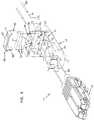
- FIG. 2is an exploded view of the fiber optic connector assembly of FIG. 1 .
- FIG. 3is a cross-sectional view of the fiber optic connector assembly taken on line 3 - 3 of FIG. 1 .
- the fiber optic connector assembly 11for use in field terminating an optical fiber or optical fibers is shown.
- the fiber optic connector assembly 11includes a carrier, generally designated 13 , and at least one connector, generally designated 15 .
- the connector 15 of the subject embodiment of the present inventionwill be described with regard to an LX.5 connector, which has been described in detail in U.S. Pat. Nos. 5,883,995 and 6,142,676 and hereby incorporated by reference, it will be understood by those skilled in the art that the scope of the present invention is not limited to the use of an LX.5-type connector. While the teachings of the present invention could be used with one or more connectors 15 , the subject embodiment of the present invention will be described as having two connectors without intending any limitations on the scope of the present invention.
- the carrier 13includes a connector end 17 and a cable end 19 , which is oppositely disposed from the connector end 17 .
- the connector end 17defines slots 23 for mounting the connectors 15 .
- the scope of the present inventionis not limited to the carrier 13 defining slots 23 for mounting the connectors 15 .
- Disposed between the connector end 17 and the cable end 19 of the carrier 13is a fiber support region 25 .
- the fiber support region 25includes guide ways 27 that narrow as the depth of the guide ways 27 in the fiber support region 25 increase.
- the carrier 13further defines a take-up region 29 , the purpose of which will be described subsequently, that is disposed between the connector end 17 and the fiber support region 25 .
- a termination regionis disposed between the cable end 19 of the carrier 13 and the fiber support region 25 .
- the termination region 31 of the carrier 13defines guide paths 33 that are generally aligned with the guide ways 27 and crimp tube holes 35 defined by the cable end 19 .
- the guide paths 33narrow as the depth of the guide paths 33 in the termination region 31 increase.
- the termination region 31further defines a cavity 37 .
- the cavity 37is adapted to receive a V-groove chip, generally designated 39 .
- the V-groove chip 39 in the fiber optic connector assembly 11serves as the location for the termination of the cleaved optical fibers 41 .
- the V-groove chip 39includes a base 43 and a cover 45 .
- the base 43defines V-grooves 47 that support the cleaved optical fibers 41 .
- Cones 49are disposed on either side of the V-grooves 47 in order to assist in the insertion of the cleaved optical fibers 41 into the V-grooves 47 .
- the base 43is made of a silicon material while the cover 45 is made of a transparent material such as pyrex.
- the cover 45is bonded to the base 43 .
- the termination region 31 in the carrier 13includes an adhesive region 51 disposed between the cavity 37 and the cable end 19 .
- a heat responsive adhesive elementgenerally designated 53
- a saddle assemblygenerally designated 55 .
- the heat responsive adhesive element 53is a glue pellet 53 .
- the glue pellet 53is shown as being generally rectangular in shape, although it will be understood by those skilled in the art that the scope of the present invention is not limited to the glue pellet 53 being rectangular in shape.
- the glue pellet 53includes a first surface 57 and an oppositely disposed second surface 59 . At least one pathway 61 is pre-formed in the glue pellet 53 .
- the at least one pathway 61is a channel 61 that is pre-formed in the second surface 59 of the glue pellet 53 .
- two channels 61are pre-formed in the second surface 59 .
- the channels 61are adapted to receive a portion of the cleaved optical fibers 41 and a portion of buffers 63 , which surround the cleaved optical fibers 41 .
- each of the channels 61is arcuately shaped so as to conform to the outer surface of the buffers 63 .
- the saddle assembly 55includes a saddle, generally designated 65 , and a resistor 67 .
- the glue pellet 53is in thermally conductive contact with the saddle 65 , which is in thermally conductive contact with the resistor 67 .
- the first surface 57 of the glue pellet 53is in contact with a bottom surface 69 of the saddle 65 , thereby establishing the thermally conductive contact between the glue pellet 53 and the saddle 65 .
- the resistor 67is in contact with a top surface 71 of the saddle 65 , thereby establishing the thermally conductive contact between the resistor 67 and the saddle 65 .
- a portion of the outer surface of each buffer 63is disposed in channels 61 of the glue pellet 53 . In the subject embodiment, nearly half of the outer circumference of the outer surface of the buffers 63 is disposed in the channels 61 .
- the carrier 13further includes crimp tubes 73 , which are engaged with the cable end 19 of the carrier 13 .
- the crimp tubes 73are in a press-fit engagement with the crimp tube holes 35 in the cable end 19 of the carrier 13 .
- the crimp tubes 73define passageways 75 through which the cleaved optical fibers 41 are inserted.
- Strength members/layers (e.g., Kevlar) of a fiber optic cablecan be crimped outside the crimp tube 73 for securing the fiber optic cable.
- the connector 15includes a main body 77 having a front end region 79 and an oppositely disposed back end region 81 .
- the main body 77defines a longitudinal bore 83 that extends through the front and back end regions 79 , 81 .
- a ferrule assembly, generally designated 85includes a ferrule 87 , an optical fiber 89 , a portion of which is housed in the ferrule 87 , and a hub 91 having a flange 93 connectedly engaged with the ferrule 87 .
- the ferrule assembly 85is disposed in the longitudinal bore 83 of the connector 15 such that the ferrule 87 is positioned in the front end region 79 of the main body 77 .
- the connector 15further includes a tube, generally designated 95 .
- the tube 95has a first end portion 97 and an oppositely disposed second end portion 99 and defines a passage 101 through the tube 95 .
- the first end portion 97 of the tube 95is connectedly engaged with the longitudinal bore 83 at the back end portion 81 of the main body 77 .
- the connected engagement between the tube 95 and the main body 77is a press-fit engagement.
- an inner diameter D 1 of the passage 101 at the first end portion 97 of the tube 95is smaller than an inner diameter D 2 of the passage 101 at the second end portion 99 .
- the tube 95further includes an annular groove 103 disposed in the outer surface of the tube 95 between the first end portion 97 and the second end portion 99 .
- a spring 105Disposed between the ferrule assembly 85 and the tube 95 is a spring 105 .
- a first end 107 of the spring 105abuts the flange 93 of the hub 91 while an oppositely disposed second end 109 of the spring 105 abuts an end surface 111 of the first end portion 97 of the tube 95 .
- the spring 105biases the ferrule assembly 85 toward the front end region 79 of the main body 77
- the spring 105allows for axial movement of the ferrule assembly 85 within the longitudinal bore 83 .
- the spring 105allows for at least 1 mm of axial movement of the ferrule assembly 85 .
- the connector 15can be connected to the carrier 13 .
- the connector 15is inserted into the slot 23 of the carrier 13 such that the slot 23 is disposed in the annular groove 103 of the tube 95 .
- the annular groove 103is in a press-fit engagement with the slot 23 .
- dust boots 112are inserted over fiber ends 113 of the optical fibers 89 , which extend through the longitudinal bore 83 of the main body 77 and the passage 101 of the tube 95 .
- the dust boots 112are in tight-fit engagement with the second end portion 99 of the tube 95 .
- the fiber ends 113 of the optical fibers 89are then inserted through the cones 49 of the V-groove chip 39 and into the V-grooves 47 . With the fiber ends 113 of the optical fibers 89 inserted into the V-grooves 47 of the V-groove chip 39 , the optical fibers 89 are secured to the guide ways 27 of the fiber support region 25 . In the subject embodiment, the optical fibers 89 are affixed to the guide ways 27 with an epoxy. The affixation of the optical fibers 89 in the guide ways 27 prevents the fiber ends 113 of the optical fibers 89 from moving axially within the V-grooves 47 of the V-groove chip 39 .
- the spring 105allows the ferrule assembly 85 to move axially within the longitudinal bore 83 of the main body 77 toward the carrier 13 .
- the axial movement of the ferrule assembly 85causes the optical fibers 89 to bend between the fiber support region 25 and the ferrule 87 .
- this bendhas a radius that is smaller than the minimum recommended bend radius of the optical fibers 89 , damage to the optical fibers 89 will result.
- the first dimensionis the inner diameter of the passage 101 .
- the second dimensionis a length L of the take-up region 29 . As the length L increases, the radii of the bends of the optical fibers 89 increases. Therefore, there is a directly proportional relationship between the length L and the bend radius of the optical fiber 89 .
- the inner diameter D 2 of the passage 101must be sized appropriately to account for the axial movement of the ferrule assembly 85 and the length L of the take-up region 29 . If the length L of the take-up region 29 is long, the inner diameter D 2 of the passage 101 can be smaller since the bend radius of the optical fibers 89 will be large. On the other hand, if the length L of the take-up region 29 is short, the inner diameter D 2 of the passage 101 must be larger to avoid the bend radius of the optical fibers 89 being below the minimum recommendations.
- the spring 105abuts the end surface 111 of the first end portion 97 of the tube 95 .
- the end surface 111 of the first end portion 97 of the tube 95must have sufficient surface area to support the spring 105 . Therefore, in order to provide a sufficient surface area to support the spring 105 , the inner diameter of the passage 101 should be small. As state above, the inner diameter of the passage 101 could be reduced if the length L of the take-up region 29 was sufficiently long. This would result, however, in the fiber optic connector assembly 11 having a longer overall length, which is not desirable in some applications.
- the subject embodimentresolves this dimensional conflict by having the inner diameter D 1 at the first end portion 97 of the tube 95 smaller than the inner diameter D 2 at the second end portion 99 of the tube 95 .
- the inner diameter D 1is about 950 ⁇ m while the inner diameter D 2 is about 3 mm (or about three times greater than the inner diameter D 1 ).
- the use of the fiber optic connector assembly 11 for a field terminationwill be described.
- the connector 15engaged to the carrier 13 , the optical fiber 89 affixed in the guide way 27 of the fiber support region 25 , and the fiber ends 113 inserted into the V-groove 47 of the V-groove chip 39 , a cleaved end 115 of the cleaved optical fiber 41 is inserted into the passageway 75 of the crimp tube 73 .
- the cleaved end 15 of the cleaved optical fiber 41is inserted through the channel 61 of the glue pellet 53 and into the V-groove 47 of the V-groove chip 39 .
- an index matching gelis disposed between the cleaved end 115 of the cleaved optical fiber 41 and the fiber end 113 of the optical fiber 89 .
- the index matching gelhas an index of refraction that matches the index of refraction of the glass of the optical fiber 89 and the cleaved optical fiber 41 .
- optical radiationis passed through the optical fibers 89 to assess proper alignment of the fiber end 113 and the cleaved end 115 . If optical radiation is detectable at the junction of the fiber end 113 and the cleaved end 115 as viewed through the transparent cover 45 of the V-groove chip 39 , then the alignment/abutment is not correct.
- the cleaved end 115may have to be polished or cleaned and reinserted into the V-groove 47 .
- the cleaved optical fiber 41 and the buffer 63can be secured to the fiber optic connector assembly 11 by the glue pellet 53 .
- an electrical power sourceis connected to the resistor 67 . Electrical current is passed through the resistor 67 which heats up the glue pellet 53 by way of the thermally conducting saddle 65 . As the glue pellet 53 heats up, the glue pellet 53 becomes tacky and adheres to the buffer 63 and the cleaved optical fibers 41 and closes passageways 75 of the crimp tubes 73 . When the current is interrupted, the glue pellet 53 resets to secure the buffers 63 and the cleaved optical fibers 41 in their correct position in alignment with the optical fibers 89 .
- the fiber optic connector assembly 11can be provided as an insert for a housing to protect the fiber optic connector assembly 11 from damage.
- One housing in which the fiber optic connector assembly 11 can be insertedis described in a U.S. Patent Application titled “Hybrid fiber/copper connector system and method”, with an attorney docket number of 02316.2467USI1, filed concurrently herewith, and hereby incorporated by reference.
Landscapes
- Physics & Mathematics (AREA)
- General Physics & Mathematics (AREA)
- Optics & Photonics (AREA)
- Mechanical Coupling Of Light Guides (AREA)
Abstract
Description
Claims (16)
Priority Applications (12)
| Application Number | Priority Date | Filing Date | Title |
|---|---|---|---|
| US11/735,267US7534050B2 (en) | 2007-04-13 | 2007-04-13 | Field terminatable fiber optic connector assembly |
| MX2009011033AMX2009011033A (en) | 2007-04-13 | 2008-04-11 | Field terminatable fiber optic connector assembly. |
| BRPI0810648-7A2ABRPI0810648A2 (en) | 2007-04-13 | 2008-04-11 | "FIELD TERMINABLE OPTICAL FIBER CONNECTOR SET". |
| PCT/US2008/060081WO2008128078A1 (en) | 2007-04-13 | 2008-04-11 | Field terminatable fiber optic connector assembly |
| CN2008800171826ACN101681002B (en) | 2007-04-13 | 2008-04-11 | Field terminatable fiber optic connector assembly |
| EP08745642AEP2137565A1 (en) | 2007-04-13 | 2008-04-11 | Field terminatable fiber optic connector assembly |
| US12/433,081US7766556B2 (en) | 2007-04-13 | 2009-04-30 | Field terminatable fiber optic connector assembly |
| US12/849,633US20110044590A1 (en) | 2007-04-13 | 2010-08-03 | Field terminatable fiber optic connector assembly |
| US13/455,249US8944702B2 (en) | 2007-04-13 | 2012-04-25 | Fiber optic connector with fiber take-up region |
| US14/611,936US9389372B2 (en) | 2007-04-13 | 2015-02-02 | Fiber optic connector with fiber take-up region |
| US15/206,958US10175429B2 (en) | 2007-04-13 | 2016-07-11 | Fiber optic connector with fiber take-up region |
| US16/241,097US20190243076A1 (en) | 2007-04-13 | 2019-01-07 | Fiber optic connector with fiber take-up region |
Applications Claiming Priority (1)
| Application Number | Priority Date | Filing Date | Title |
|---|---|---|---|
| US11/735,267US7534050B2 (en) | 2007-04-13 | 2007-04-13 | Field terminatable fiber optic connector assembly |
Related Child Applications (1)
| Application Number | Title | Priority Date | Filing Date |
|---|---|---|---|
| US12/433,081DivisionUS7766556B2 (en) | 2007-04-13 | 2009-04-30 | Field terminatable fiber optic connector assembly |
Publications (2)
| Publication Number | Publication Date |
|---|---|
| US20080253719A1 US20080253719A1 (en) | 2008-10-16 |
| US7534050B2true US7534050B2 (en) | 2009-05-19 |
Family
ID=39720654
Family Applications (7)
| Application Number | Title | Priority Date | Filing Date |
|---|---|---|---|
| US11/735,267Expired - Fee RelatedUS7534050B2 (en) | 2007-04-13 | 2007-04-13 | Field terminatable fiber optic connector assembly |
| US12/433,081Expired - Fee RelatedUS7766556B2 (en) | 2007-04-13 | 2009-04-30 | Field terminatable fiber optic connector assembly |
| US12/849,633AbandonedUS20110044590A1 (en) | 2007-04-13 | 2010-08-03 | Field terminatable fiber optic connector assembly |
| US13/455,249ActiveUS8944702B2 (en) | 2007-04-13 | 2012-04-25 | Fiber optic connector with fiber take-up region |
| US14/611,936ActiveUS9389372B2 (en) | 2007-04-13 | 2015-02-02 | Fiber optic connector with fiber take-up region |
| US15/206,958ActiveUS10175429B2 (en) | 2007-04-13 | 2016-07-11 | Fiber optic connector with fiber take-up region |
| US16/241,097AbandonedUS20190243076A1 (en) | 2007-04-13 | 2019-01-07 | Fiber optic connector with fiber take-up region |
Family Applications After (6)
| Application Number | Title | Priority Date | Filing Date |
|---|---|---|---|
| US12/433,081Expired - Fee RelatedUS7766556B2 (en) | 2007-04-13 | 2009-04-30 | Field terminatable fiber optic connector assembly |
| US12/849,633AbandonedUS20110044590A1 (en) | 2007-04-13 | 2010-08-03 | Field terminatable fiber optic connector assembly |
| US13/455,249ActiveUS8944702B2 (en) | 2007-04-13 | 2012-04-25 | Fiber optic connector with fiber take-up region |
| US14/611,936ActiveUS9389372B2 (en) | 2007-04-13 | 2015-02-02 | Fiber optic connector with fiber take-up region |
| US15/206,958ActiveUS10175429B2 (en) | 2007-04-13 | 2016-07-11 | Fiber optic connector with fiber take-up region |
| US16/241,097AbandonedUS20190243076A1 (en) | 2007-04-13 | 2019-01-07 | Fiber optic connector with fiber take-up region |
Country Status (6)
| Country | Link |
|---|---|
| US (7) | US7534050B2 (en) |
| EP (1) | EP2137565A1 (en) |
| CN (1) | CN101681002B (en) |
| BR (1) | BRPI0810648A2 (en) |
| MX (1) | MX2009011033A (en) |
| WO (1) | WO2008128078A1 (en) |
Cited By (17)
| Publication number | Priority date | Publication date | Assignee | Title |
|---|---|---|---|---|
| US20090269011A1 (en)* | 2007-11-30 | 2009-10-29 | Jarrod Scadden | Hybrid fiber/copper connector system and method |
| US20100119197A1 (en)* | 2008-07-10 | 2010-05-13 | Jarrod Scadden | Field Terminable Fiber Optic Connector Assembly |
| US20100209052A1 (en)* | 2008-04-11 | 2010-08-19 | Xin Liu | Fiber optic connector assembly and method for venting gas inside a fiber optic connector sub-assembly |
| US20110002586A1 (en)* | 2009-04-06 | 2011-01-06 | Ponharith Nhep | Fiber optic connector and method for assembling |
| US20110019963A1 (en)* | 2009-05-29 | 2011-01-27 | Kenneth Allen Skluzacek | Field Terminable Fiber Optic Connector Assembly |
| US20110091165A1 (en)* | 2009-10-15 | 2011-04-21 | Seldon David Benjamin | Fiber Optic Connectors and Structures for Large Core Optical Fibers and Methods for Making the Same |
| US20110088434A1 (en)* | 2009-10-21 | 2011-04-21 | Adc Gmbh | Apparatus for mechanically splicing optic fibers |
| US20110217010A1 (en)* | 2010-03-02 | 2011-09-08 | Adc Telecommunications, Inc. | Fiber optic cable assembly |
| US20120167387A1 (en)* | 2010-09-14 | 2012-07-05 | Adc Telecommunictions, Inc. | Method of terminating a fiber optic cable |
| US8636425B2 (en) | 2011-03-15 | 2014-01-28 | Adc Telecommunications, Inc. | Fiber optic connector |
| US8702323B2 (en) | 2011-03-15 | 2014-04-22 | Adc Telecommunications, Inc. | Strain relief boot for a fiber optic connector |
| US8944702B2 (en) | 2007-04-13 | 2015-02-03 | Adc Telecommunications, Inc. | Fiber optic connector with fiber take-up region |
| US9176285B2 (en) | 2012-05-03 | 2015-11-03 | Adc Telecommunications, Inc. | Fiber optic connector |
| US9268102B2 (en) | 2012-02-07 | 2016-02-23 | Tyco Electronics Raychem Bvba | Cable termination assembly and method for connectors |
| US20160356965A1 (en)* | 2015-06-05 | 2016-12-08 | Sanwa Denki Kogyo Co., Ltd. | Boot for optical connector ferrule |
| US9891391B2 (en) | 2015-12-04 | 2018-02-13 | Sanwa Denki Kogyo Co. Ltd. | Boot for optical connector ferrule |
| US10444443B2 (en) | 2013-06-27 | 2019-10-15 | CommScope Connectivity Belgium BVBA | Fiber optic cable anchoring device for use with fiber optic connectors and methods of using the same |
Families Citing this family (14)
| Publication number | Priority date | Publication date | Assignee | Title |
|---|---|---|---|---|
| US20100080517A1 (en)* | 2008-09-29 | 2010-04-01 | Cline Timothy S | Fiber optic connector assembly employing fiber movement support and method of assembly |
| US8485735B2 (en)* | 2008-12-19 | 2013-07-16 | US Conec, Ltd | Field install fiber clip and method of use |
| US9002168B2 (en)* | 2012-09-17 | 2015-04-07 | Avago Technologies General Ip (Singapore) Pte. Ltd. | Cleave holder, an assembly, and methods for cleaving ends of optical fibers and securing them to a multi-optical fiber connector module |
| US8917968B2 (en)* | 2012-11-06 | 2014-12-23 | Corning Optical Communications LLC | Furcation plugs having segregated channels to guide epoxy into passageways for optical fiber furcation, and related assemblies and methods |
| WO2014118225A1 (en) | 2013-01-29 | 2014-08-07 | Tyco Electronics Raychem Bvba | Fiber optic connector with fiber end protection |
| US8998504B2 (en)* | 2013-02-21 | 2015-04-07 | Avago Technologies General Ip (Singapore) Pte. Ltd. | User-configurable optical fiber link |
| US9146360B2 (en)* | 2013-09-11 | 2015-09-29 | Verizon Patent And Licensing Inc. | V-groove ferrule mating sleeve |
| TWM474924U (en)* | 2013-09-27 | 2014-03-21 | Fiberon Technologies Inc | Optical connector with space and angle position switching |
| AU2016222612B2 (en) | 2015-02-25 | 2021-08-05 | Ppc Broadband, Inc. | Connectors for micro-duct terminations of fiber optic cable |
| EP3345026B1 (en) | 2015-08-31 | 2020-10-14 | Commscope Technologies LLC | Splice-on fiber optic connector |
| CN106324762B (en)* | 2016-11-14 | 2019-06-25 | 武汉光迅科技股份有限公司 | A kind of yin-yang wave splitting/composing device module |
| US11194101B2 (en)* | 2018-09-11 | 2021-12-07 | Senko Advanced Components, Inc. | LC one piece front loaded ferrule with unitary retainer and ferrule holder |
| WO2020180806A1 (en) | 2019-03-02 | 2020-09-10 | Senko Advanced Components, Inc | Fiber management enclosure for a fiber optic connector assembly and method of use |
| US12158620B2 (en)* | 2020-02-14 | 2024-12-03 | Senko Advanced Components, Inc. | Field terminated fiber optic connector |
Citations (47)
| Publication number | Priority date | Publication date | Assignee | Title |
|---|---|---|---|---|
| JPS59177513A (en) | 1983-03-28 | 1984-10-08 | Sumitomo Electric Ind Ltd | fiber optic connector |
| US4588256A (en) | 1982-09-07 | 1986-05-13 | Minnesota Mining And Manufacturing Company | Optical fiber connector |
| JPS61284710A (en) | 1985-06-11 | 1986-12-15 | Furukawa Electric Co Ltd:The | How to secure a connector to an optical fiber terminal |
| US4669820A (en)* | 1982-06-05 | 1987-06-02 | Amp Incorporated | Optical fiber termination method, terminal splice and connector therefor |
| US4746194A (en) | 1984-07-17 | 1988-05-24 | Peter Rasmussen | Method of mounting an end portion of an optical fibre in an optical fibre connector |
| US4787699A (en) | 1987-09-01 | 1988-11-29 | Hughes Aircraft Company | Fiber optic terminus |
| US4850671A (en) | 1987-03-26 | 1989-07-25 | Siemens Aktiengesellschaft | Connector device for light waveguides |
| US4984865A (en) | 1989-11-17 | 1991-01-15 | Minnesota Mining And Manufacturing Company | Thermoplastic adhesive mounting apparatus and method for an optical fiber connector |
| JPH0440402A (en) | 1990-06-06 | 1992-02-10 | Seiko Instr Inc | Device for hardening adhesive for assembling optical connector |
| EP0479415A2 (en) | 1990-09-06 | 1992-04-08 | The Whitaker Corporation | Fiber optic splicer |
| USRE34005E (en) | 1985-11-20 | 1992-07-21 | Raychem Corporation | Contact for terminating an optical fiber |
| US5151961A (en)* | 1992-02-20 | 1992-09-29 | Northern Telecom Limited | Ferrule alignment assembly for blind mating optical fiber connector |
| US5418876A (en) | 1994-02-18 | 1995-05-23 | Augat Communications Products, Inc. | Fiber optic connector with epoxy preform |
| US5446819A (en) | 1994-07-14 | 1995-08-29 | Itt Industries, Inc. | Termination tool and method for optical fibre cables |
| US5469521A (en) | 1994-05-23 | 1995-11-21 | Itt Corporation | Seal between buffer tube and optical fiber |
| EP0689070A1 (en) | 1994-06-24 | 1995-12-27 | Sumitomo Wiring Systems, Ltd. | Terminal treatment device for a plastic fibre |
| US5611017A (en) | 1995-06-01 | 1997-03-11 | Minnesota Mining And Manufacturing Co. | Fiber optic ribbon cable with pre-installed locations for subsequent connectorization |
| US5631986A (en) | 1994-04-29 | 1997-05-20 | Minnesota Mining And Manufacturing Co. | Optical fiber ferrule |
| WO1997023797A1 (en) | 1995-12-22 | 1997-07-03 | Minnesota Mining And Manufacturing Company | Receptacle for electro-optical device |
| US5647043A (en)* | 1995-10-12 | 1997-07-08 | Lucent Technologies, Inc. | Unipartite jack receptacle |
| EP0810455A1 (en) | 1996-05-30 | 1997-12-03 | Fujikura Ltd. | Optical fiber mechanical splice |
| US5806175A (en)* | 1996-12-20 | 1998-09-15 | Siecor Corporation | Crimp assembly for connecting an optical fiber ribbon cord to a connector |
| US5883995A (en) | 1997-05-20 | 1999-03-16 | Adc Telecommunications, Inc. | Fiber connector and adapter |
| EP0916974A2 (en) | 1997-11-13 | 1999-05-19 | The Whitaker Corporation | Multiple fiber splice element and connector |
| US6054007A (en) | 1997-04-09 | 2000-04-25 | 3M Innovative Properties Company | Method of forming shaped adhesives |
| US6079880A (en)* | 1997-03-20 | 2000-06-27 | Telefonaktiebolaget Lm Ericsson | Connector for at least one optical fibre |
| US6142676A (en) | 1997-05-20 | 2000-11-07 | Adc Telecommunications, Inc. | Fiber connector and adaptor |
| US6179658B1 (en) | 1998-08-06 | 2001-01-30 | Delphi Technologies, Inc. | Sealing arrangement between an electrical connector and an electrical conductor |
| US20010033730A1 (en)* | 2000-02-17 | 2001-10-25 | Vernon Fentress | Adapter retaining method and pull-protector for fiber optic cable |
| US6325670B2 (en) | 2000-03-16 | 2001-12-04 | Yazaki Corporation | Waterproof connector |
| US6341898B1 (en)* | 1999-09-08 | 2002-01-29 | Yazaki Corporation | Receptacle, process for producing the same and optical connector containing the same |
| US20020067894A1 (en) | 2000-08-14 | 2002-06-06 | Thomas Scanzillo | Ferrule having bondable insert |
| US6432511B1 (en) | 1997-06-06 | 2002-08-13 | International Business Machines Corp. | Thermoplastic adhesive preform for heat sink attachment |
| US20020154868A1 (en) | 2001-02-05 | 2002-10-24 | Roland Kraus | Housing having a retention member for an optical fiber |
| US6513989B1 (en)* | 1997-06-24 | 2003-02-04 | Tyco Electronics Logistics Ag | Ferrule container for holding a multiple optical fiber disposed in a ferrule, and a connector for connecting multiple optical fibers |
| US20030063868A1 (en)* | 2000-02-17 | 2003-04-03 | Vernon Fentress | Fiber optic cable termination devices and methods |
| US6782182B2 (en) | 2001-04-23 | 2004-08-24 | Shipley Company, L.L.C. | Optical fiber attached to a substrate |
| US6811321B1 (en)* | 2000-02-11 | 2004-11-02 | Huber & Suhner Ag | Optical connector for simultaneously connecting a plurality of fiber optical cables and adapter for said connector |
| US6811323B2 (en) | 2000-06-12 | 2004-11-02 | Krone Gmbh | Assembly and method for use in terminating an optical fiber or fibers |
| US6819858B2 (en) | 2000-10-26 | 2004-11-16 | Shipley Company, L.L.C. | Fiber array with V-groove chip and mount |
| US6848837B2 (en) | 2002-02-08 | 2005-02-01 | Simon Charles Gilligan | Fibre-optic connector |
| US20050135755A1 (en)* | 2003-12-23 | 2005-06-23 | Sepehr Kiani | Modular fiber optic connector system |
| US6945706B2 (en) | 2002-09-27 | 2005-09-20 | Corning Cable Systems Llc | Ferrule guide member and ferrule with precision optical fiber placement and method for assembling same |
| US20050213899A1 (en)* | 2004-03-25 | 2005-09-29 | Hurley William C | Fiber optic drop cables suitable for outdoor fiber to the subscriber applications |
| US20050276559A1 (en)* | 2004-06-14 | 2005-12-15 | Bianchi Robert J | Drive for system for processing fiber optic connectors |
| US20050281509A1 (en)* | 2004-06-18 | 2005-12-22 | 3M Innovative Properties Company | Optical connector system with EMI shielding |
| US7147384B2 (en) | 2004-03-26 | 2006-12-12 | 3M Innovative Properties Company | Small form factor optical connector with thermoplastic adhesive |
Family Cites Families (48)
| Publication number | Priority date | Publication date | Assignee | Title |
|---|---|---|---|---|
| US3395244A (en) | 1967-03-14 | 1968-07-30 | Koehler Rudolph | Strain relief for electric cords |
| DK143620A (en) | 1974-06-20 | |||
| US4190316A (en) | 1978-02-02 | 1980-02-26 | The Deutsch Company | Lens connector for optical fibers |
| US4225214A (en) | 1978-09-18 | 1980-09-30 | Trw Inc. | Connector construction |
| FR2440008A1 (en) | 1978-10-23 | 1980-05-23 | Souriau & Cie | CONNECTOR FOR OPTICAL FIBERS AND DEVICE FOR MOUNTING FIBERS ON PLUGS DIRECTLY FOR USE ON CONNECTOR |
| US4279467A (en) | 1979-11-05 | 1981-07-21 | International Telephone And Telegraph Corporation | Fiber optic connector |
| US4320938A (en) | 1979-12-26 | 1982-03-23 | Bell Telephone Laboratories, Incorporated | Resilient optical fiber connector |
| US4291941A (en) | 1980-02-04 | 1981-09-29 | The Deutsch Company Electronic Components Division | Optical fiber connector |
| US4373777A (en) | 1980-08-11 | 1983-02-15 | International Telephone And Telegraph Corporation | Connector and cable assembly |
| IT1189525B (en) | 1986-05-19 | 1988-02-04 | Pirelli Cavi Spa | METHOD FOR AXIAL POSITIONING OF AN OPTICAL FIBER IN AN EXPANDED BEAM CONNECTOR AND RELATED CONNECTOR |
| JPH03143140A (en) | 1989-10-30 | 1991-06-18 | Hitachi Ltd | Inter-station data transfer method |
| US5261019A (en) | 1992-01-02 | 1993-11-09 | Adc Telecommunications, Inc. | Fiber optic connector |
| US5321784A (en) | 1993-02-18 | 1994-06-14 | Minnesota Mining And Manufacturing Company | Pull-proof, modular fiber optic connector system |
| US5390272A (en) | 1993-08-31 | 1995-02-14 | Amphenol Corporation | Fiber optic cable connector with strain relief boot |
| EP0784218A4 (en) | 1995-07-12 | 1999-09-08 | Sumitomo Electric Industries | FIBER OPTICAL PLUG AND PLUG |
| JPH09307134A (en)* | 1996-05-13 | 1997-11-28 | Fujitsu Ltd | Light receiving element, its optical module, and optical unit |
| JPH10246839A (en)* | 1997-03-05 | 1998-09-14 | Fujitsu Ltd | Optical semiconductor module |
| US5915056A (en) | 1997-08-06 | 1999-06-22 | Lucent Technologies Inc. | Optical fiber strain relief device |
| JPH11119064A (en)* | 1997-10-17 | 1999-04-30 | Fujitsu Ltd | Optical transmission terminal |
| EP1199584B1 (en)* | 1999-06-01 | 2014-09-17 | Nippon Telegraph And Telephone Corporation | Optical plug connector, method of manufacture and assembly tool |
| US6688782B1 (en)* | 1999-08-23 | 2004-02-10 | Corning Cable Systems Llc | Universal ferrule |
| US6419402B1 (en) | 1999-12-13 | 2002-07-16 | Adc Telecommunications, Inc. | Fiber optic connector and method for assembling |
| JP2001208935A (en)* | 2000-01-24 | 2001-08-03 | Fujitsu Ltd | Optical connector connection structure |
| US7467896B2 (en)* | 2000-05-26 | 2008-12-23 | Corning Cable Systems Llc | Fiber optic drop cables and preconnectorized assemblies |
| US7113679B2 (en)* | 2000-05-26 | 2006-09-26 | Corning Cable Systems, Llc | Fiber optic drop cables and preconnectorized assemblies having toning portions |
| US6456768B1 (en)* | 2000-10-18 | 2002-09-24 | Fitel Usa Corp. | Optical fiber cable tracing system |
| US6543941B1 (en)* | 2000-10-18 | 2003-04-08 | Fitel Usa Corp. | Jack receptacle having optical and electrical ports |
| US6428215B1 (en) | 2000-12-27 | 2002-08-06 | Adc Telecommunications, Inc. | Tunable fiber optic connector and method for assembling |
| US6669377B2 (en)* | 2001-06-11 | 2003-12-30 | Corning Cable Systems Llc | Fiber optic connector and an associated pin retainer |
| JP4158365B2 (en)* | 2001-08-27 | 2008-10-01 | ブラザー工業株式会社 | Network terminal equipment |
| US6916120B2 (en) | 2002-01-30 | 2005-07-12 | Adc Telecommunications, Inc. | Fiber optic connector and method |
| US20040057672A1 (en) | 2002-09-19 | 2004-03-25 | Doss Donald G. | Process for field terminating an optical fiber connector |
| JP2005189332A (en)* | 2003-12-24 | 2005-07-14 | Three M Innovative Properties Co | Optical connector, optical fiber with connector, optical fiber connecting apparatus and method for connecting optical fiber |
| US7331717B2 (en)* | 2004-07-01 | 2008-02-19 | Amphenol Corporation | Flexible optical interconnection system |
| JP4457111B2 (en)* | 2004-08-20 | 2010-04-28 | 住友電気工業株式会社 | Optical connector and optical connector assembling method |
| EP1932037B1 (en)* | 2005-10-05 | 2013-06-19 | Tyco Electronics Raychem BVBA | Optical fibre connection devices |
| DE602007013895D1 (en) | 2006-06-15 | 2011-05-26 | Tyco Electronics Corp | CONNECTOR FOR COVERED FIBER CABLE |
| US7677812B2 (en) | 2006-07-31 | 2010-03-16 | Tyco Electronics Corporation | Strain relief boot for cable connector |
| US7578623B2 (en)* | 2006-08-21 | 2009-08-25 | Intel Corporation | Aligning lens carriers and ferrules with alignment frames |
| US7490994B2 (en) | 2006-11-29 | 2009-02-17 | Adc Telecommunications, Inc. | Hybrid fiber/copper connector system and method |
| US7534050B2 (en) | 2007-04-13 | 2009-05-19 | Adc Telecommunications, Inc. | Field terminatable fiber optic connector assembly |
| JP5071980B2 (en) | 2008-02-15 | 2012-11-14 | 日本電信電話株式会社 | Fiber optic connector |
| WO2009155037A2 (en) | 2008-05-28 | 2009-12-23 | Adc Telecommunications, Inc. | Fiber optic cable |
| JP5281959B2 (en) | 2008-06-12 | 2013-09-04 | 株式会社精工技研 | An optical connector stop ring, an optical fiber cord with an optical connector using the stop ring, and a method of manufacturing an optical fiber cord with an optical connector. |
| US7758256B2 (en) | 2008-09-29 | 2010-07-20 | Tyco Electronics Corporation | Connector for tight-jacketed optical fiber cable |
| ES2854839T3 (en) | 2009-04-06 | 2021-09-23 | Commscope Technologies Llc | Fiber Optic Connector |
| US7942591B2 (en) | 2009-04-07 | 2011-05-17 | Tyco Electronics Corporation | Bend limiting boot |
| US8636425B2 (en) | 2011-03-15 | 2014-01-28 | Adc Telecommunications, Inc. | Fiber optic connector |
- 2007
- 2007-04-13USUS11/735,267patent/US7534050B2/ennot_activeExpired - Fee Related
- 2008
- 2008-04-11WOPCT/US2008/060081patent/WO2008128078A1/enactiveApplication Filing
- 2008-04-11BRBRPI0810648-7A2Apatent/BRPI0810648A2/ennot_activeIP Right Cessation
- 2008-04-11CNCN2008800171826Apatent/CN101681002B/ennot_activeExpired - Fee Related
- 2008-04-11MXMX2009011033Apatent/MX2009011033A/enactiveIP Right Grant
- 2008-04-11EPEP08745642Apatent/EP2137565A1/ennot_activeWithdrawn
- 2009
- 2009-04-30USUS12/433,081patent/US7766556B2/ennot_activeExpired - Fee Related
- 2010
- 2010-08-03USUS12/849,633patent/US20110044590A1/ennot_activeAbandoned
- 2012
- 2012-04-25USUS13/455,249patent/US8944702B2/enactiveActive
- 2015
- 2015-02-02USUS14/611,936patent/US9389372B2/enactiveActive
- 2016
- 2016-07-11USUS15/206,958patent/US10175429B2/enactiveActive
- 2019
- 2019-01-07USUS16/241,097patent/US20190243076A1/ennot_activeAbandoned
Patent Citations (48)
| Publication number | Priority date | Publication date | Assignee | Title |
|---|---|---|---|---|
| US4669820A (en)* | 1982-06-05 | 1987-06-02 | Amp Incorporated | Optical fiber termination method, terminal splice and connector therefor |
| US4588256A (en) | 1982-09-07 | 1986-05-13 | Minnesota Mining And Manufacturing Company | Optical fiber connector |
| JPS59177513A (en) | 1983-03-28 | 1984-10-08 | Sumitomo Electric Ind Ltd | fiber optic connector |
| US4746194A (en) | 1984-07-17 | 1988-05-24 | Peter Rasmussen | Method of mounting an end portion of an optical fibre in an optical fibre connector |
| JPS61284710A (en) | 1985-06-11 | 1986-12-15 | Furukawa Electric Co Ltd:The | How to secure a connector to an optical fiber terminal |
| USRE34005E (en) | 1985-11-20 | 1992-07-21 | Raychem Corporation | Contact for terminating an optical fiber |
| US4850671A (en) | 1987-03-26 | 1989-07-25 | Siemens Aktiengesellschaft | Connector device for light waveguides |
| US4787699A (en) | 1987-09-01 | 1988-11-29 | Hughes Aircraft Company | Fiber optic terminus |
| US4984865A (en) | 1989-11-17 | 1991-01-15 | Minnesota Mining And Manufacturing Company | Thermoplastic adhesive mounting apparatus and method for an optical fiber connector |
| JPH0440402A (en) | 1990-06-06 | 1992-02-10 | Seiko Instr Inc | Device for hardening adhesive for assembling optical connector |
| EP0479415A2 (en) | 1990-09-06 | 1992-04-08 | The Whitaker Corporation | Fiber optic splicer |
| US5151961A (en)* | 1992-02-20 | 1992-09-29 | Northern Telecom Limited | Ferrule alignment assembly for blind mating optical fiber connector |
| US5418876A (en) | 1994-02-18 | 1995-05-23 | Augat Communications Products, Inc. | Fiber optic connector with epoxy preform |
| US5631986A (en) | 1994-04-29 | 1997-05-20 | Minnesota Mining And Manufacturing Co. | Optical fiber ferrule |
| US5469521A (en) | 1994-05-23 | 1995-11-21 | Itt Corporation | Seal between buffer tube and optical fiber |
| EP0689070A1 (en) | 1994-06-24 | 1995-12-27 | Sumitomo Wiring Systems, Ltd. | Terminal treatment device for a plastic fibre |
| US5446819A (en) | 1994-07-14 | 1995-08-29 | Itt Industries, Inc. | Termination tool and method for optical fibre cables |
| US5611017A (en) | 1995-06-01 | 1997-03-11 | Minnesota Mining And Manufacturing Co. | Fiber optic ribbon cable with pre-installed locations for subsequent connectorization |
| US5647043A (en)* | 1995-10-12 | 1997-07-08 | Lucent Technologies, Inc. | Unipartite jack receptacle |
| WO1997023797A1 (en) | 1995-12-22 | 1997-07-03 | Minnesota Mining And Manufacturing Company | Receptacle for electro-optical device |
| EP0810455A1 (en) | 1996-05-30 | 1997-12-03 | Fujikura Ltd. | Optical fiber mechanical splice |
| US5806175A (en)* | 1996-12-20 | 1998-09-15 | Siecor Corporation | Crimp assembly for connecting an optical fiber ribbon cord to a connector |
| US6079880A (en)* | 1997-03-20 | 2000-06-27 | Telefonaktiebolaget Lm Ericsson | Connector for at least one optical fibre |
| US6054007A (en) | 1997-04-09 | 2000-04-25 | 3M Innovative Properties Company | Method of forming shaped adhesives |
| US5883995A (en) | 1997-05-20 | 1999-03-16 | Adc Telecommunications, Inc. | Fiber connector and adapter |
| US6142676A (en) | 1997-05-20 | 2000-11-07 | Adc Telecommunications, Inc. | Fiber connector and adaptor |
| US6432511B1 (en) | 1997-06-06 | 2002-08-13 | International Business Machines Corp. | Thermoplastic adhesive preform for heat sink attachment |
| US6893591B2 (en) | 1997-06-06 | 2005-05-17 | International Business Machines Corporation | Thermoplastic adhesive preform for heat sink attachment |
| US6513989B1 (en)* | 1997-06-24 | 2003-02-04 | Tyco Electronics Logistics Ag | Ferrule container for holding a multiple optical fiber disposed in a ferrule, and a connector for connecting multiple optical fibers |
| EP0916974A2 (en) | 1997-11-13 | 1999-05-19 | The Whitaker Corporation | Multiple fiber splice element and connector |
| US6179658B1 (en) | 1998-08-06 | 2001-01-30 | Delphi Technologies, Inc. | Sealing arrangement between an electrical connector and an electrical conductor |
| US6341898B1 (en)* | 1999-09-08 | 2002-01-29 | Yazaki Corporation | Receptacle, process for producing the same and optical connector containing the same |
| US6811321B1 (en)* | 2000-02-11 | 2004-11-02 | Huber & Suhner Ag | Optical connector for simultaneously connecting a plurality of fiber optical cables and adapter for said connector |
| US20010033730A1 (en)* | 2000-02-17 | 2001-10-25 | Vernon Fentress | Adapter retaining method and pull-protector for fiber optic cable |
| US20030063868A1 (en)* | 2000-02-17 | 2003-04-03 | Vernon Fentress | Fiber optic cable termination devices and methods |
| US6325670B2 (en) | 2000-03-16 | 2001-12-04 | Yazaki Corporation | Waterproof connector |
| US6811323B2 (en) | 2000-06-12 | 2004-11-02 | Krone Gmbh | Assembly and method for use in terminating an optical fiber or fibers |
| US20020067894A1 (en) | 2000-08-14 | 2002-06-06 | Thomas Scanzillo | Ferrule having bondable insert |
| US6819858B2 (en) | 2000-10-26 | 2004-11-16 | Shipley Company, L.L.C. | Fiber array with V-groove chip and mount |
| US20020154868A1 (en) | 2001-02-05 | 2002-10-24 | Roland Kraus | Housing having a retention member for an optical fiber |
| US6782182B2 (en) | 2001-04-23 | 2004-08-24 | Shipley Company, L.L.C. | Optical fiber attached to a substrate |
| US6848837B2 (en) | 2002-02-08 | 2005-02-01 | Simon Charles Gilligan | Fibre-optic connector |
| US6945706B2 (en) | 2002-09-27 | 2005-09-20 | Corning Cable Systems Llc | Ferrule guide member and ferrule with precision optical fiber placement and method for assembling same |
| US20050135755A1 (en)* | 2003-12-23 | 2005-06-23 | Sepehr Kiani | Modular fiber optic connector system |
| US20050213899A1 (en)* | 2004-03-25 | 2005-09-29 | Hurley William C | Fiber optic drop cables suitable for outdoor fiber to the subscriber applications |
| US7147384B2 (en) | 2004-03-26 | 2006-12-12 | 3M Innovative Properties Company | Small form factor optical connector with thermoplastic adhesive |
| US20050276559A1 (en)* | 2004-06-14 | 2005-12-15 | Bianchi Robert J | Drive for system for processing fiber optic connectors |
| US20050281509A1 (en)* | 2004-06-18 | 2005-12-22 | 3M Innovative Properties Company | Optical connector system with EMI shielding |
Non-Patent Citations (1)
| Title |
|---|
| International Search Report and Written Opinion mailed Sep. 19, 2008. |
Cited By (50)
| Publication number | Priority date | Publication date | Assignee | Title |
|---|---|---|---|---|
| US10175429B2 (en) | 2007-04-13 | 2019-01-08 | Commscope Technologies Llc | Fiber optic connector with fiber take-up region |
| US9389372B2 (en) | 2007-04-13 | 2016-07-12 | Commscope Technologies Llc | Fiber optic connector with fiber take-up region |
| US8944702B2 (en) | 2007-04-13 | 2015-02-03 | Adc Telecommunications, Inc. | Fiber optic connector with fiber take-up region |
| US8083416B2 (en) | 2007-11-30 | 2011-12-27 | Adc Telecommunications, Inc. | Hybrid fiber/copper connector system and method |
| US8678666B2 (en) | 2007-11-30 | 2014-03-25 | Adc Telecommunications, Inc. | Hybrid fiber/copper connector system and method |
| US20090269011A1 (en)* | 2007-11-30 | 2009-10-29 | Jarrod Scadden | Hybrid fiber/copper connector system and method |
| US20100209052A1 (en)* | 2008-04-11 | 2010-08-19 | Xin Liu | Fiber optic connector assembly and method for venting gas inside a fiber optic connector sub-assembly |
| US10481329B2 (en) | 2008-07-10 | 2019-11-19 | Commscope Technologies Llc | Field terminable fiber optic connector assembly |
| US9703040B2 (en) | 2008-07-10 | 2017-07-11 | Commscope Technologies Llc | Field terminable fiber optic connector assembly |
| US9146352B2 (en) | 2008-07-10 | 2015-09-29 | Adc Telecommunications, Inc. | Field terminable fiber optic connector assembly |
| US10162113B2 (en) | 2008-07-10 | 2018-12-25 | Commscope Technologies Llc | Field terminable fiber optic connector assembly |
| US8430572B2 (en) | 2008-07-10 | 2013-04-30 | Adc Telecommunications, Inc. | Field terminable fiber optic connector assembly |
| US20100119197A1 (en)* | 2008-07-10 | 2010-05-13 | Jarrod Scadden | Field Terminable Fiber Optic Connector Assembly |
| US8342755B2 (en) | 2009-04-06 | 2013-01-01 | Adc Telecommunications, Inc. | Fiber optic connector and method for assembling |
| US20110002586A1 (en)* | 2009-04-06 | 2011-01-06 | Ponharith Nhep | Fiber optic connector and method for assembling |
| US8573858B2 (en)* | 2009-05-29 | 2013-11-05 | Adc Telecommunications, Inc. | Field terminable fiber optic connector assembly |
| US20140050444A1 (en)* | 2009-05-29 | 2014-02-20 | Adc Telecommunications, Inc. | Field Terminable Fiber Optic Connector Assembly |
| US8926192B2 (en)* | 2009-05-29 | 2015-01-06 | Adc Telecommunications, Inc. | Field terminable fiber optic connector assembly |
| US20110019963A1 (en)* | 2009-05-29 | 2011-01-27 | Kenneth Allen Skluzacek | Field Terminable Fiber Optic Connector Assembly |
| US9158075B2 (en)* | 2009-10-15 | 2015-10-13 | Corning Incorporated | Fiber optic connectors and structures for large core optical fibers and methods for making the same |
| US20110091165A1 (en)* | 2009-10-15 | 2011-04-21 | Seldon David Benjamin | Fiber Optic Connectors and Structures for Large Core Optical Fibers and Methods for Making the Same |
| US8358899B2 (en) | 2009-10-21 | 2013-01-22 | Adc Gmbh | Apparatus for mechanically splicing optic fibers |
| US20110088434A1 (en)* | 2009-10-21 | 2011-04-21 | Adc Gmbh | Apparatus for mechanically splicing optic fibers |
| US20110217010A1 (en)* | 2010-03-02 | 2011-09-08 | Adc Telecommunications, Inc. | Fiber optic cable assembly |
| USRE50314E1 (en) | 2010-03-02 | 2025-02-25 | Commscope Technologies Llc | Fiber optic cable assembly and method |
| US8363994B2 (en) | 2010-03-02 | 2013-01-29 | Adc Telecommunications, Inc. | Fiber optic cable assembly |
| US8544171B2 (en)* | 2010-09-14 | 2013-10-01 | Adc Telecommunications, Inc. | Method of terminating a fiber optic cable |
| US20120167387A1 (en)* | 2010-09-14 | 2012-07-05 | Adc Telecommunictions, Inc. | Method of terminating a fiber optic cable |
| US9151904B2 (en) | 2011-03-15 | 2015-10-06 | Adc Telecommunications, Inc. | Fiber optic connector |
| US10146011B2 (en) | 2011-03-15 | 2018-12-04 | Commscope Technologies Llc | Fiber optic connector |
| US12405430B2 (en) | 2011-03-15 | 2025-09-02 | Commscope Technologies Llc | Fiber optic connector |
| US8636425B2 (en) | 2011-03-15 | 2014-01-28 | Adc Telecommunications, Inc. | Fiber optic connector |
| US9500813B2 (en) | 2011-03-15 | 2016-11-22 | Commscope Technologies Llc | Fiber optic connector |
| US11782224B2 (en) | 2011-03-15 | 2023-10-10 | Commscope Technologies Llc | Fiber optic connector |
| US10859771B2 (en) | 2011-03-15 | 2020-12-08 | Commscope Technologies Llc | Fiber optic connector |
| US9841566B2 (en) | 2011-03-15 | 2017-12-12 | Commscope Technologies Llc | Fiber optic connector |
| US10495822B2 (en) | 2011-03-15 | 2019-12-03 | Commscope Technologies Llc | Fiber optic connector |
| US8702323B2 (en) | 2011-03-15 | 2014-04-22 | Adc Telecommunications, Inc. | Strain relief boot for a fiber optic connector |
| US9268102B2 (en) | 2012-02-07 | 2016-02-23 | Tyco Electronics Raychem Bvba | Cable termination assembly and method for connectors |
| US10036859B2 (en) | 2012-02-07 | 2018-07-31 | CommScope Connectivity Belgium BVBA | Cable termination assembly and method for connectors |
| US9625660B2 (en) | 2012-02-07 | 2017-04-18 | CommScope Connectivity Belgium BVBA | Cable termination assembly and method for connectors |
| US9176285B2 (en) | 2012-05-03 | 2015-11-03 | Adc Telecommunications, Inc. | Fiber optic connector |
| US10371899B2 (en)* | 2012-05-03 | 2019-08-06 | Commscope Technologies Llc | Fiber optic connector |
| US20170336573A1 (en)* | 2012-05-03 | 2017-11-23 | Commscope Technologies Llc | Fiber optic connector |
| US9638869B2 (en) | 2012-05-03 | 2017-05-02 | Commscope Technologies Llc | Fiber optic connector |
| US10444443B2 (en) | 2013-06-27 | 2019-10-15 | CommScope Connectivity Belgium BVBA | Fiber optic cable anchoring device for use with fiber optic connectors and methods of using the same |
| US12117658B2 (en) | 2013-06-27 | 2024-10-15 | CommScope Connectivity Belgium BVBA | Fiber optic cable anchoring device for use with fiber optic connectors and methods of using the same |
| US20160356965A1 (en)* | 2015-06-05 | 2016-12-08 | Sanwa Denki Kogyo Co., Ltd. | Boot for optical connector ferrule |
| US9778423B2 (en)* | 2015-06-05 | 2017-10-03 | Sanwa Denki Kogyo Co., Ltd. | Boot for optical connector ferrule |
| US9891391B2 (en) | 2015-12-04 | 2018-02-13 | Sanwa Denki Kogyo Co. Ltd. | Boot for optical connector ferrule |
Also Published As
| Publication number | Publication date |
|---|---|
| US20170115457A1 (en) | 2017-04-27 |
| WO2008128078A1 (en) | 2008-10-23 |
| MX2009011033A (en) | 2009-11-19 |
| BRPI0810648A2 (en) | 2014-11-04 |
| US10175429B2 (en) | 2019-01-08 |
| US9389372B2 (en) | 2016-07-12 |
| CN101681002A (en) | 2010-03-24 |
| CN101681002B (en) | 2012-02-01 |
| US20150253518A1 (en) | 2015-09-10 |
| US20080253719A1 (en) | 2008-10-16 |
| US7766556B2 (en) | 2010-08-03 |
| US20120328247A1 (en) | 2012-12-27 |
| US20190243076A1 (en) | 2019-08-08 |
| EP2137565A1 (en) | 2009-12-30 |
| US8944702B2 (en) | 2015-02-03 |
| US20110044590A1 (en) | 2011-02-24 |
| US20090238522A1 (en) | 2009-09-24 |
Similar Documents
| Publication | Publication Date | Title |
|---|---|---|
| US7534050B2 (en) | Field terminatable fiber optic connector assembly | |
| US10481329B2 (en) | Field terminable fiber optic connector assembly | |
| US7929819B2 (en) | Field termination kit | |
| GB2397895A (en) | Optical fibre connector with clamp to grip ferrule | |
| CN103959120B (en) | Optical connector assembly | |
| EP3783408B1 (en) | Field installable rugged optical terminus | |
| US7192194B2 (en) | Universal adapter for fiber optic connectors | |
| US20020012504A1 (en) | Angled fiber optic connector | |
| EP3206066B1 (en) | Preconnectorized optical cable assembly |
Legal Events
| Date | Code | Title | Description |
|---|---|---|---|
| AS | Assignment | Owner name:ADC TELECOMMUNICATIONS, INC., MINNESOTA Free format text:ASSIGNMENT OF ASSIGNORS INTEREST;ASSIGNOR:KACHMAR, WAYNE M.;REEL/FRAME:019515/0074 Effective date:20070531 | |
| STCF | Information on status: patent grant | Free format text:PATENTED CASE | |
| FPAY | Fee payment | Year of fee payment:4 | |
| AS | Assignment | Owner name:TYCO ELECTRONICS SERVICES GMBH, SWITZERLAND Free format text:ASSIGNMENT OF ASSIGNORS INTEREST;ASSIGNOR:ADC TELECOMMUNICATIONS, INC.;REEL/FRAME:036060/0174 Effective date:20110930 | |
| AS | Assignment | Owner name:COMMSCOPE EMEA LIMITED, IRELAND Free format text:ASSIGNMENT OF ASSIGNORS INTEREST;ASSIGNOR:TYCO ELECTRONICS SERVICES GMBH;REEL/FRAME:036956/0001 Effective date:20150828 | |
| AS | Assignment | Owner name:COMMSCOPE TECHNOLOGIES LLC, NORTH CAROLINA Free format text:ASSIGNMENT OF ASSIGNORS INTEREST;ASSIGNOR:COMMSCOPE EMEA LIMITED;REEL/FRAME:037012/0001 Effective date:20150828 | |
| AS | Assignment | Owner name:JPMORGAN CHASE BANK, N.A., AS COLLATERAL AGENT, ILLINOIS Free format text:PATENT SECURITY AGREEMENT (TERM);ASSIGNOR:COMMSCOPE TECHNOLOGIES LLC;REEL/FRAME:037513/0709 Effective date:20151220 Owner name:JPMORGAN CHASE BANK, N.A., AS COLLATERAL AGENT, ILLINOIS Free format text:PATENT SECURITY AGREEMENT (ABL);ASSIGNOR:COMMSCOPE TECHNOLOGIES LLC;REEL/FRAME:037514/0196 Effective date:20151220 Owner name:JPMORGAN CHASE BANK, N.A., AS COLLATERAL AGENT, IL Free format text:PATENT SECURITY AGREEMENT (ABL);ASSIGNOR:COMMSCOPE TECHNOLOGIES LLC;REEL/FRAME:037514/0196 Effective date:20151220 Owner name:JPMORGAN CHASE BANK, N.A., AS COLLATERAL AGENT, IL Free format text:PATENT SECURITY AGREEMENT (TERM);ASSIGNOR:COMMSCOPE TECHNOLOGIES LLC;REEL/FRAME:037513/0709 Effective date:20151220 | |
| FPAY | Fee payment | Year of fee payment:8 | |
| AS | Assignment | Owner name:COMMSCOPE, INC. OF NORTH CAROLINA, NORTH CAROLINA Free format text:RELEASE BY SECURED PARTY;ASSIGNOR:JPMORGAN CHASE BANK, N.A.;REEL/FRAME:048840/0001 Effective date:20190404 Owner name:ALLEN TELECOM LLC, ILLINOIS Free format text:RELEASE BY SECURED PARTY;ASSIGNOR:JPMORGAN CHASE BANK, N.A.;REEL/FRAME:048840/0001 Effective date:20190404 Owner name:REDWOOD SYSTEMS, INC., NORTH CAROLINA Free format text:RELEASE BY SECURED PARTY;ASSIGNOR:JPMORGAN CHASE BANK, N.A.;REEL/FRAME:048840/0001 Effective date:20190404 Owner name:ANDREW LLC, NORTH CAROLINA Free format text:RELEASE BY SECURED PARTY;ASSIGNOR:JPMORGAN CHASE BANK, N.A.;REEL/FRAME:048840/0001 Effective date:20190404 Owner name:COMMSCOPE TECHNOLOGIES LLC, NORTH CAROLINA Free format text:RELEASE BY SECURED PARTY;ASSIGNOR:JPMORGAN CHASE BANK, N.A.;REEL/FRAME:048840/0001 Effective date:20190404 Owner name:ALLEN TELECOM LLC, ILLINOIS Free format text:RELEASE BY SECURED PARTY;ASSIGNOR:JPMORGAN CHASE BANK, N.A.;REEL/FRAME:049260/0001 Effective date:20190404 Owner name:REDWOOD SYSTEMS, INC., NORTH CAROLINA Free format text:RELEASE BY SECURED PARTY;ASSIGNOR:JPMORGAN CHASE BANK, N.A.;REEL/FRAME:049260/0001 Effective date:20190404 Owner name:ANDREW LLC, NORTH CAROLINA Free format text:RELEASE BY SECURED PARTY;ASSIGNOR:JPMORGAN CHASE BANK, N.A.;REEL/FRAME:049260/0001 Effective date:20190404 Owner name:COMMSCOPE TECHNOLOGIES LLC, NORTH CAROLINA Free format text:RELEASE BY SECURED PARTY;ASSIGNOR:JPMORGAN CHASE BANK, N.A.;REEL/FRAME:049260/0001 Effective date:20190404 Owner name:COMMSCOPE, INC. OF NORTH CAROLINA, NORTH CAROLINA Free format text:RELEASE BY SECURED PARTY;ASSIGNOR:JPMORGAN CHASE BANK, N.A.;REEL/FRAME:049260/0001 Effective date:20190404 | |
| AS | Assignment | Owner name:WILMINGTON TRUST, NATIONAL ASSOCIATION, AS COLLATE Free format text:PATENT SECURITY AGREEMENT;ASSIGNOR:COMMSCOPE TECHNOLOGIES LLC;REEL/FRAME:049892/0051 Effective date:20190404 Owner name:JPMORGAN CHASE BANK, N.A., NEW YORK Free format text:ABL SECURITY AGREEMENT;ASSIGNORS:COMMSCOPE, INC. OF NORTH CAROLINA;COMMSCOPE TECHNOLOGIES LLC;ARRIS ENTERPRISES LLC;AND OTHERS;REEL/FRAME:049892/0396 Effective date:20190404 Owner name:JPMORGAN CHASE BANK, N.A., NEW YORK Free format text:TERM LOAN SECURITY AGREEMENT;ASSIGNORS:COMMSCOPE, INC. OF NORTH CAROLINA;COMMSCOPE TECHNOLOGIES LLC;ARRIS ENTERPRISES LLC;AND OTHERS;REEL/FRAME:049905/0504 Effective date:20190404 Owner name:WILMINGTON TRUST, NATIONAL ASSOCIATION, AS COLLATERAL AGENT, CONNECTICUT Free format text:PATENT SECURITY AGREEMENT;ASSIGNOR:COMMSCOPE TECHNOLOGIES LLC;REEL/FRAME:049892/0051 Effective date:20190404 | |
| FEPP | Fee payment procedure | Free format text:MAINTENANCE FEE REMINDER MAILED (ORIGINAL EVENT CODE: REM.); ENTITY STATUS OF PATENT OWNER: LARGE ENTITY | |
| LAPS | Lapse for failure to pay maintenance fees | Free format text:PATENT EXPIRED FOR FAILURE TO PAY MAINTENANCE FEES (ORIGINAL EVENT CODE: EXP.); ENTITY STATUS OF PATENT OWNER: LARGE ENTITY | |
| STCH | Information on status: patent discontinuation | Free format text:PATENT EXPIRED DUE TO NONPAYMENT OF MAINTENANCE FEES UNDER 37 CFR 1.362 | |
| FP | Lapsed due to failure to pay maintenance fee | Effective date:20210519 | |
| AS | Assignment | Owner name:RUCKUS WIRELESS, LLC (F/K/A RUCKUS WIRELESS, INC.), NORTH CAROLINA Free format text:RELEASE OF SECURITY INTEREST AT REEL/FRAME 049905/0504;ASSIGNOR:JPMORGAN CHASE BANK, N.A., AS COLLATERAL AGENT;REEL/FRAME:071477/0255 Effective date:20241217 Owner name:COMMSCOPE TECHNOLOGIES LLC, NORTH CAROLINA Free format text:RELEASE OF SECURITY INTEREST AT REEL/FRAME 049905/0504;ASSIGNOR:JPMORGAN CHASE BANK, N.A., AS COLLATERAL AGENT;REEL/FRAME:071477/0255 Effective date:20241217 Owner name:COMMSCOPE, INC. OF NORTH CAROLINA, NORTH CAROLINA Free format text:RELEASE OF SECURITY INTEREST AT REEL/FRAME 049905/0504;ASSIGNOR:JPMORGAN CHASE BANK, N.A., AS COLLATERAL AGENT;REEL/FRAME:071477/0255 Effective date:20241217 Owner name:ARRIS SOLUTIONS, INC., NORTH CAROLINA Free format text:RELEASE OF SECURITY INTEREST AT REEL/FRAME 049905/0504;ASSIGNOR:JPMORGAN CHASE BANK, N.A., AS COLLATERAL AGENT;REEL/FRAME:071477/0255 Effective date:20241217 Owner name:ARRIS TECHNOLOGY, INC., NORTH CAROLINA Free format text:RELEASE OF SECURITY INTEREST AT REEL/FRAME 049905/0504;ASSIGNOR:JPMORGAN CHASE BANK, N.A., AS COLLATERAL AGENT;REEL/FRAME:071477/0255 Effective date:20241217 Owner name:ARRIS ENTERPRISES LLC (F/K/A ARRIS ENTERPRISES, INC.), NORTH CAROLINA Free format text:RELEASE OF SECURITY INTEREST AT REEL/FRAME 049905/0504;ASSIGNOR:JPMORGAN CHASE BANK, N.A., AS COLLATERAL AGENT;REEL/FRAME:071477/0255 Effective date:20241217 |