US7533998B2 - Vehicle accessory module - Google Patents
Vehicle accessory moduleDownload PDFInfo
- Publication number
- US7533998B2 US7533998B2US11/716,834US71683407AUS7533998B2US 7533998 B2US7533998 B2US 7533998B2US 71683407 AUS71683407 AUS 71683407AUS 7533998 B2US7533998 B2US 7533998B2
- Authority
- US
- United States
- Prior art keywords
- accessory module
- windshield
- vehicle
- accessory
- mounting
- Prior art date
- Legal status (The legal status is an assumption and is not a legal conclusion. Google has not performed a legal analysis and makes no representation as to the accuracy of the status listed.)
- Expired - Lifetime
Links
- 238000001514detection methodMethods0.000claimsdescription25
- 230000004044responseEffects0.000claimsdescription5
- 230000003044adaptive effectEffects0.000claimsdescription3
- 230000007613environmental effectEffects0.000claimsdescription3
- 230000004297night visionEffects0.000claimsdescription3
- 239000004606Fillers/ExtendersSubstances0.000description94
- 239000010408filmSubstances0.000description31
- 230000006870functionEffects0.000description31
- 239000000463materialSubstances0.000description23
- 238000004891communicationMethods0.000description20
- 239000000758substrateSubstances0.000description20
- 210000003128headAnatomy0.000description19
- 230000033001locomotionEffects0.000description18
- 238000009434installationMethods0.000description15
- 230000036961partial effectEffects0.000description12
- 239000004033plasticSubstances0.000description12
- 229920003023plasticPolymers0.000description12
- 230000000717retained effectEffects0.000description11
- 230000000712assemblyEffects0.000description10
- 238000000429assemblyMethods0.000description10
- 239000011521glassSubstances0.000description9
- 238000003384imaging methodMethods0.000description9
- 238000000034methodMethods0.000description9
- 230000008569processEffects0.000description8
- 238000007789sealingMethods0.000description7
- 229910052751metalInorganic materials0.000description6
- 239000002184metalSubstances0.000description6
- 230000003287optical effectEffects0.000description6
- 229910052782aluminiumInorganic materials0.000description5
- XAGFODPZIPBFFR-UHFFFAOYSA-NaluminiumChemical compound[Al]XAGFODPZIPBFFR-UHFFFAOYSA-N0.000description5
- 229920006351engineering plasticPolymers0.000description5
- 238000011900installation processMethods0.000description5
- 239000007769metal materialSubstances0.000description5
- 230000002441reversible effectEffects0.000description5
- 239000007787solidSubstances0.000description5
- 239000004677NylonSubstances0.000description4
- 229910001229Pot metalInorganic materials0.000description4
- 238000005299abrasionMethods0.000description4
- 239000000853adhesiveSubstances0.000description4
- 230000001070adhesive effectEffects0.000description4
- 238000005452bendingMethods0.000description4
- 230000005540biological transmissionEffects0.000description4
- 239000011248coating agentSubstances0.000description4
- 238000000576coating methodMethods0.000description4
- 239000004020conductorSubstances0.000description4
- 238000001816coolingMethods0.000description4
- 230000008878couplingEffects0.000description4
- 238000010168coupling processMethods0.000description4
- 238000005859coupling reactionMethods0.000description4
- 239000000428dustSubstances0.000description4
- 238000000465mouldingMethods0.000description4
- 229920001778nylonPolymers0.000description4
- 238000012545processingMethods0.000description4
- XUIMIQQOPSSXEZ-UHFFFAOYSA-NSiliconChemical compound[Si]XUIMIQQOPSSXEZ-UHFFFAOYSA-N0.000description3
- 239000000356contaminantSubstances0.000description3
- 238000013461designMethods0.000description3
- -1dirtSubstances0.000description3
- 230000004438eyesightEffects0.000description3
- 230000004313glareEffects0.000description3
- 238000005286illuminationMethods0.000description3
- 238000007373indentationMethods0.000description3
- 238000004519manufacturing processMethods0.000description3
- 238000012544monitoring processMethods0.000description3
- 230000009467reductionEffects0.000description3
- 230000002829reductive effectEffects0.000description3
- 229910052710siliconInorganic materials0.000description3
- 239000010703siliconSubstances0.000description3
- 239000000779smokeSubstances0.000description3
- 230000004913activationEffects0.000description2
- 239000000919ceramicSubstances0.000description2
- 230000008859changeEffects0.000description2
- 238000010276constructionMethods0.000description2
- 230000006378damageEffects0.000description2
- 239000013536elastomeric materialSubstances0.000description2
- 239000004973liquid crystal related substanceSubstances0.000description2
- 238000012423maintenanceMethods0.000description2
- 239000011159matrix materialSubstances0.000description2
- 230000007246mechanismEffects0.000description2
- 239000002952polymeric resinSubstances0.000description2
- 229920001296polysiloxanePolymers0.000description2
- 238000003825pressingMethods0.000description2
- 230000010076replicationEffects0.000description2
- 239000000126substanceSubstances0.000description2
- 229920003002synthetic resinPolymers0.000description2
- 239000010409thin filmSubstances0.000description2
- 238000009423ventilationMethods0.000description2
- RYGMFSIKBFXOCR-UHFFFAOYSA-NCopperChemical compound[Cu]RYGMFSIKBFXOCR-UHFFFAOYSA-N0.000description1
- BQCADISMDOOEFD-UHFFFAOYSA-NSilverChemical compound[Ag]BQCADISMDOOEFD-UHFFFAOYSA-N0.000description1
- 206010041349SomnolenceDiseases0.000description1
- NIXOWILDQLNWCW-UHFFFAOYSA-Nacrylic acid groupChemical groupC(C=C)(=O)ONIXOWILDQLNWCW-UHFFFAOYSA-N0.000description1
- 238000013459approachMethods0.000description1
- 230000008901benefitEffects0.000description1
- 239000003990capacitorSubstances0.000description1
- 238000005266castingMethods0.000description1
- 230000001413cellular effectEffects0.000description1
- 235000019504cigarettesNutrition0.000description1
- 230000008602contractionEffects0.000description1
- 229910052802copperInorganic materials0.000description1
- 239000010949copperSubstances0.000description1
- 238000005260corrosionMethods0.000description1
- 230000007797corrosionEffects0.000description1
- 239000002537cosmeticSubstances0.000description1
- 238000005520cutting processMethods0.000description1
- 230000007423decreaseEffects0.000description1
- 230000001419dependent effectEffects0.000description1
- 230000008021depositionEffects0.000description1
- 238000010586diagramMethods0.000description1
- 238000004512die castingMethods0.000description1
- 230000009977dual effectEffects0.000description1
- 230000000694effectsEffects0.000description1
- 238000001125extrusionMethods0.000description1
- 239000006260foamSubstances0.000description1
- 230000002209hydrophobic effectEffects0.000description1
- 238000001746injection mouldingMethods0.000description1
- 238000003780insertionMethods0.000description1
- 230000037431insertionEffects0.000description1
- 239000012212insulatorSubstances0.000description1
- 238000010409ironingMethods0.000description1
- 238000010030laminatingMethods0.000description1
- 238000003698laser cuttingMethods0.000description1
- 230000000670limiting effectEffects0.000description1
- 230000014759maintenance of locationEffects0.000description1
- 230000013011matingEffects0.000description1
- 238000012986modificationMethods0.000description1
- 230000004048modificationEffects0.000description1
- 230000007935neutral effectEffects0.000description1
- 230000005693optoelectronicsEffects0.000description1
- 239000003973paintSubstances0.000description1
- 238000010422paintingMethods0.000description1
- 239000004417polycarbonateSubstances0.000description1
- 229920000515polycarbonatePolymers0.000description1
- 229920000642polymerPolymers0.000description1
- 239000002861polymer materialSubstances0.000description1
- 230000035755proliferationEffects0.000description1
- 230000002035prolonged effectEffects0.000description1
- 230000005855radiationEffects0.000description1
- 238000002310reflectometryMethods0.000description1
- 239000012858resilient materialSubstances0.000description1
- 229920005989resinPolymers0.000description1
- 239000011347resinSubstances0.000description1
- 238000012552reviewMethods0.000description1
- 238000005096rolling processMethods0.000description1
- 229920003031santoprenePolymers0.000description1
- 238000006748scratchingMethods0.000description1
- 230000002393scratching effectEffects0.000description1
- 230000035945sensitivityEffects0.000description1
- 229910052709silverInorganic materials0.000description1
- 239000004332silverSubstances0.000description1
- 201000002859sleep apneaDiseases0.000description1
- 239000004984smart glassSubstances0.000description1
- 238000002791soakingMethods0.000description1
- 239000007779soft materialSubstances0.000description1
- 239000000243solutionSubstances0.000description1
- 229920001169thermoplasticPolymers0.000description1
- 229920002725thermoplastic elastomerPolymers0.000description1
- 239000004416thermosoftening plasticSubstances0.000description1
- 238000002834transmittanceMethods0.000description1
- 230000000007visual effectEffects0.000description1
- 235000012431wafersNutrition0.000description1
Images


Classifications
- B—PERFORMING OPERATIONS; TRANSPORTING
- B60—VEHICLES IN GENERAL
- B60R—VEHICLES, VEHICLE FITTINGS, OR VEHICLE PARTS, NOT OTHERWISE PROVIDED FOR
- B60R1/00—Optical viewing arrangements; Real-time viewing arrangements for drivers or passengers using optical image capturing systems, e.g. cameras or video systems specially adapted for use in or on vehicles
- B60R1/10—Front-view mirror arrangements; Periscope arrangements, i.e. optical devices using combinations of mirrors, lenses, prisms or the like ; Other mirror arrangements giving a view from above or under the vehicle
- B—PERFORMING OPERATIONS; TRANSPORTING
- B60—VEHICLES IN GENERAL
- B60R—VEHICLES, VEHICLE FITTINGS, OR VEHICLE PARTS, NOT OTHERWISE PROVIDED FOR
- B60R1/00—Optical viewing arrangements; Real-time viewing arrangements for drivers or passengers using optical image capturing systems, e.g. cameras or video systems specially adapted for use in or on vehicles
- B60R1/02—Rear-view mirror arrangements
- B60R1/04—Rear-view mirror arrangements mounted inside vehicle
- B—PERFORMING OPERATIONS; TRANSPORTING
- B60—VEHICLES IN GENERAL
- B60R—VEHICLES, VEHICLE FITTINGS, OR VEHICLE PARTS, NOT OTHERWISE PROVIDED FOR
- B60R1/00—Optical viewing arrangements; Real-time viewing arrangements for drivers or passengers using optical image capturing systems, e.g. cameras or video systems specially adapted for use in or on vehicles
- B60R1/12—Mirror assemblies combined with other articles, e.g. clocks
- B—PERFORMING OPERATIONS; TRANSPORTING
- B60—VEHICLES IN GENERAL
- B60R—VEHICLES, VEHICLE FITTINGS, OR VEHICLE PARTS, NOT OTHERWISE PROVIDED FOR
- B60R11/00—Arrangements for holding or mounting articles, not otherwise provided for
- B60R11/04—Mounting of cameras operative during drive; Arrangement of controls thereof relative to the vehicle
- H—ELECTRICITY
- H04—ELECTRIC COMMUNICATION TECHNIQUE
- H04N—PICTORIAL COMMUNICATION, e.g. TELEVISION
- H04N23/00—Cameras or camera modules comprising electronic image sensors; Control thereof
- H04N23/60—Control of cameras or camera modules
- H04N23/698—Control of cameras or camera modules for achieving an enlarged field of view, e.g. panoramic image capture
- H—ELECTRICITY
- H04—ELECTRIC COMMUNICATION TECHNIQUE
- H04N—PICTORIAL COMMUNICATION, e.g. TELEVISION
- H04N25/00—Circuitry of solid-state image sensors [SSIS]; Control thereof
- H04N25/70—SSIS architectures; Circuits associated therewith
- H04N25/76—Addressed sensors, e.g. MOS or CMOS sensors
- H—ELECTRICITY
- H04—ELECTRIC COMMUNICATION TECHNIQUE
- H04N—PICTORIAL COMMUNICATION, e.g. TELEVISION
- H04N7/00—Television systems
- H04N7/18—Closed-circuit television [CCTV] systems, i.e. systems in which the video signal is not broadcast
- H—ELECTRICITY
- H04—ELECTRIC COMMUNICATION TECHNIQUE
- H04N—PICTORIAL COMMUNICATION, e.g. TELEVISION
- H04N7/00—Television systems
- H04N7/18—Closed-circuit television [CCTV] systems, i.e. systems in which the video signal is not broadcast
- H04N7/183—Closed-circuit television [CCTV] systems, i.e. systems in which the video signal is not broadcast for receiving images from a single remote source
- B—PERFORMING OPERATIONS; TRANSPORTING
- B60—VEHICLES IN GENERAL
- B60R—VEHICLES, VEHICLE FITTINGS, OR VEHICLE PARTS, NOT OTHERWISE PROVIDED FOR
- B60R1/00—Optical viewing arrangements; Real-time viewing arrangements for drivers or passengers using optical image capturing systems, e.g. cameras or video systems specially adapted for use in or on vehicles
- B60R1/12—Mirror assemblies combined with other articles, e.g. clocks
- B60R1/1207—Mirror assemblies combined with other articles, e.g. clocks with lamps; with turn indicators
- B—PERFORMING OPERATIONS; TRANSPORTING
- B60—VEHICLES IN GENERAL
- B60R—VEHICLES, VEHICLE FITTINGS, OR VEHICLE PARTS, NOT OTHERWISE PROVIDED FOR
- B60R1/00—Optical viewing arrangements; Real-time viewing arrangements for drivers or passengers using optical image capturing systems, e.g. cameras or video systems specially adapted for use in or on vehicles
- B60R1/12—Mirror assemblies combined with other articles, e.g. clocks
- B60R2001/1215—Mirror assemblies combined with other articles, e.g. clocks with information displays
- B—PERFORMING OPERATIONS; TRANSPORTING
- B60—VEHICLES IN GENERAL
- B60R—VEHICLES, VEHICLE FITTINGS, OR VEHICLE PARTS, NOT OTHERWISE PROVIDED FOR
- B60R1/00—Optical viewing arrangements; Real-time viewing arrangements for drivers or passengers using optical image capturing systems, e.g. cameras or video systems specially adapted for use in or on vehicles
- B60R1/12—Mirror assemblies combined with other articles, e.g. clocks
- B60R2001/1223—Mirror assemblies combined with other articles, e.g. clocks with sensors or transducers
- B—PERFORMING OPERATIONS; TRANSPORTING
- B60—VEHICLES IN GENERAL
- B60R—VEHICLES, VEHICLE FITTINGS, OR VEHICLE PARTS, NOT OTHERWISE PROVIDED FOR
- B60R1/00—Optical viewing arrangements; Real-time viewing arrangements for drivers or passengers using optical image capturing systems, e.g. cameras or video systems specially adapted for use in or on vehicles
- B60R1/12—Mirror assemblies combined with other articles, e.g. clocks
- B60R2001/123—Mirror assemblies combined with other articles, e.g. clocks with thermometers
- B—PERFORMING OPERATIONS; TRANSPORTING
- B60—VEHICLES IN GENERAL
- B60R—VEHICLES, VEHICLE FITTINGS, OR VEHICLE PARTS, NOT OTHERWISE PROVIDED FOR
- B60R1/00—Optical viewing arrangements; Real-time viewing arrangements for drivers or passengers using optical image capturing systems, e.g. cameras or video systems specially adapted for use in or on vehicles
- B60R1/12—Mirror assemblies combined with other articles, e.g. clocks
- B60R2001/1246—Mirror assemblies combined with other articles, e.g. clocks with clocks
- B—PERFORMING OPERATIONS; TRANSPORTING
- B60—VEHICLES IN GENERAL
- B60R—VEHICLES, VEHICLE FITTINGS, OR VEHICLE PARTS, NOT OTHERWISE PROVIDED FOR
- B60R1/00—Optical viewing arrangements; Real-time viewing arrangements for drivers or passengers using optical image capturing systems, e.g. cameras or video systems specially adapted for use in or on vehicles
- B60R1/12—Mirror assemblies combined with other articles, e.g. clocks
- B60R2001/1253—Mirror assemblies combined with other articles, e.g. clocks with cameras, video cameras or video screens
- B—PERFORMING OPERATIONS; TRANSPORTING
- B60—VEHICLES IN GENERAL
- B60R—VEHICLES, VEHICLE FITTINGS, OR VEHICLE PARTS, NOT OTHERWISE PROVIDED FOR
- B60R1/00—Optical viewing arrangements; Real-time viewing arrangements for drivers or passengers using optical image capturing systems, e.g. cameras or video systems specially adapted for use in or on vehicles
- B60R1/12—Mirror assemblies combined with other articles, e.g. clocks
- B60R2001/1261—Mirror assemblies combined with other articles, e.g. clocks with antennae
- B—PERFORMING OPERATIONS; TRANSPORTING
- B60—VEHICLES IN GENERAL
- B60R—VEHICLES, VEHICLE FITTINGS, OR VEHICLE PARTS, NOT OTHERWISE PROVIDED FOR
- B60R1/00—Optical viewing arrangements; Real-time viewing arrangements for drivers or passengers using optical image capturing systems, e.g. cameras or video systems specially adapted for use in or on vehicles
- B60R1/12—Mirror assemblies combined with other articles, e.g. clocks
- B60R2001/1276—Mirror assemblies combined with other articles, e.g. clocks with radio receivers, loud-speakers or buzzers
- B—PERFORMING OPERATIONS; TRANSPORTING
- B60—VEHICLES IN GENERAL
- B60R—VEHICLES, VEHICLE FITTINGS, OR VEHICLE PARTS, NOT OTHERWISE PROVIDED FOR
- B60R1/00—Optical viewing arrangements; Real-time viewing arrangements for drivers or passengers using optical image capturing systems, e.g. cameras or video systems specially adapted for use in or on vehicles
- B60R1/12—Mirror assemblies combined with other articles, e.g. clocks
- B60R2001/1284—Mirror assemblies combined with other articles, e.g. clocks with communication systems other than radio-receivers, e.g. keyless entry systems, navigation systems; with anti-collision systems
- B—PERFORMING OPERATIONS; TRANSPORTING
- B60—VEHICLES IN GENERAL
- B60R—VEHICLES, VEHICLE FITTINGS, OR VEHICLE PARTS, NOT OTHERWISE PROVIDED FOR
- B60R2300/00—Details of viewing arrangements using cameras and displays, specially adapted for use in a vehicle
- B60R2300/10—Details of viewing arrangements using cameras and displays, specially adapted for use in a vehicle characterised by the type of camera system used
- B60R2300/106—Details of viewing arrangements using cameras and displays, specially adapted for use in a vehicle characterised by the type of camera system used using night vision cameras
- B—PERFORMING OPERATIONS; TRANSPORTING
- B60—VEHICLES IN GENERAL
- B60R—VEHICLES, VEHICLE FITTINGS, OR VEHICLE PARTS, NOT OTHERWISE PROVIDED FOR
- B60R2300/00—Details of viewing arrangements using cameras and displays, specially adapted for use in a vehicle
- B60R2300/10—Details of viewing arrangements using cameras and displays, specially adapted for use in a vehicle characterised by the type of camera system used
- B60R2300/108—Details of viewing arrangements using cameras and displays, specially adapted for use in a vehicle characterised by the type of camera system used using 'non-standard' camera systems, e.g. camera sensor used for additional purposes i.a. rain sensor, camera sensor split in multiple image areas
- B—PERFORMING OPERATIONS; TRANSPORTING
- B60—VEHICLES IN GENERAL
- B60R—VEHICLES, VEHICLE FITTINGS, OR VEHICLE PARTS, NOT OTHERWISE PROVIDED FOR
- B60R2300/00—Details of viewing arrangements using cameras and displays, specially adapted for use in a vehicle
- B60R2300/80—Details of viewing arrangements using cameras and displays, specially adapted for use in a vehicle characterised by the intended use of the viewing arrangement
- B60R2300/8033—Details of viewing arrangements using cameras and displays, specially adapted for use in a vehicle characterised by the intended use of the viewing arrangement for pedestrian protection
Definitions
- the present inventionrelates generally to accessories useful for a vehicle and, more particularly, to accessories used in windshield electronic modules and interior rearview mirror assemblies.
- Certain accessories of a vehicletypically are mounted tight against an interior surface of a windshield or window. This is required in some cases to maintain a desired distance between a light emitter/light sensor and the interior surface of the windshield, and/or to optically couple the component to the windshield, and/or to substantially seal the component at the windshield to prevent dust, dirt, smoke or other contaminants from affecting the component.
- the camera or sensormay be a contacting type of sensor, where the sensor is in contact with the interior surface of the windshield, or may be spaced from the windshield. It is desired to provide a blacked out area or ceramic frit region in areas where such accessories are mounted at the windshield, in order to enhance the appearance of the vehicle. Therefore, an aperture or port may have to be formed in the frit layer for the camera or image sensor to be aligned with. However, the frit layer then may include the port or aperture even for vehicles where the camera-based accessory is not selected as an option. In order to provide an appropriate frit layer for the camera-based accessory option, the vehicle manufacturer may need to plan or design different frit layers for different options available to the vehicle, which may result in a proliferation of windshields and part numbers for the different optional accessories.
- the present inventionis intended to provide an accessory module which is readily mountable at an interior surface of a windshield of a vehicle.
- the accessory moduleis mounted and preferably loaded to and against the windshield to maintain close and tight coupling of accessories within the module, such as a rain sensor, temperature sensor, image sensor and/or the like.
- the accessory modulemay have a head portion or accessory housing which is attached to or movably attached to a base portion which is mountable at an interior surface of a vehicle windshield.
- an accessory system for a vehiclecomprises a vehicle windshield having a first attachment member affixed thereto, an accessory module assembly comprising a mounting portion and a head portion, and an interior rearview mirror assembly.
- the mounting portionis configured to mount to the first attachment member and extends generally upward when mounted to the first attachment member.
- the mounting portionhas a second attachment member.
- the head portionis at an upper portion of the mounting portion and extends generally horizontally and rearwardly from the upper portion with respect to the vehicle when the mounting portion is mounted to the first attachment member.
- the head portioncomprises electronic circuitry for at least one accessory.
- the interior rearview mirror assemblycomprises a mirror casing and a reflective element, and is mountable to the second attachment member.
- the head portion of the accessory module assemblyextends from the upper portion of the mounting portion generally above the mirror casing.
- the head portionis at least one of viewable and user accessible above the mirror casing when the mirror assembly is mounted to the second attachment member.
- the head portionmay be movably attached to the upper portion of the mounting portion and may be movable relative to the mounting portion.
- the head portionmay be pivotally mounted to the upper portion of the mounting portion and may be pivotable sidewardly relative to the mounting portion about a generally vertical pivot axis to adjust the angle of the accessory housing with respect to the driver of the vehicle, and/or may be pivotable upwardly and downwardly relative to the mounting portion about a generally horizontal pivot axis to adjust the angle of the accessory housing with respect to the driver of the vehicle.
- the head portionmay be articulatably mounted to the upper portion of the mounting portion and may be articulatable relative to the mounting portion about a pivot axis, wherein the pivot axis comprises a generally horizontal pivot axis when the mounting portion is mounted to the first attachment member.
- the head portionmay be articulatable between a mounting orientation or folded orientation, where the head portion is positioned to be generally along the mounting portion, and an in-use orientation or non-folded orientation, where the head portion extends generally horizontally and rearwardly from the upper portion with respect to the vehicle when the mounting portion is mounted to the first attachment member.
- the head portionmay be articulatable to the mounting orientation to facilitate mounting of the accessory module assembly to the first mirror attachment member.
- the head portionmay extend generally horizontally and rearwardly with respect to the vehicle and generally above the mirror casing when the mounting portion is mounted to the first attachment member and when the head portion is in the in-use orientation and when the interior rearview mirror assembly is mounted to the second mounting member.
- the accessory module assemblymay comprise a biasing element which biases the head portion toward the in-use orientation relative to the mounting portion.
- the head portionmay comprise a display element and/or a user input device associated with the accessory.
- the display element and/or user input devicemay be viewable and/or user accessible above the mirror casing when the mirror assembly is mounted to the second attachment member.
- the at least one accessorymay comprise at least two accessories.
- the accessories of the head portionmay at least comprise a compass sensor and a compass display, or a microphone and a user input device (where the accessory module may provide a vehicular telecommunication function and/or a telephonic function), or a user input device and a garage door opener device (where the garage door opener device is operable to actuate a garage door opener for opening a garage door) or the like.
- an accessory system for a vehiclecomprises a vehicle windshield having a first attachment member affixed thereto, an accessory module assembly comprising a mounting portion and a head portion, and an interior rearview mirror assembly.
- the mounting portionis configured to mount to the first attachment member and to extend generally upward when mounted to the first attachment member.
- the mounting portionhas a second attachment member.
- the head portionis pivotally attached to the mounting portion and houses electronic circuitry of at least one accessory.
- the interior rearview mirror assemblycomprises a mirror casing and a reflective element and is mountable to the second attachment member.
- the head portion of the accessory module assemblyextends from the mounting portion generally above the mirror casing, such that the head portion is viewable and/or user accessible above the mirror casing when the mirror assembly is mounted to the second attachment member.
- an accessory system for a vehiclecomprises a vehicle windshield having an attachment member affixed thereto, an accessory module assembly and an interior rearview mirror assembly.
- the accessory module assemblycomprises a mounting portion for mounting the accessory module assembly to the attachment member, and a head portion for housing electronic circuitry associated with at least one accessory.
- the head portionis articulatably mounted to the mounting portion and is articulatable relative to the mounting portion between a folded orientation, wherein the head portion is folded generally along the mounting portion, and a non-folded orientation, wherein the head portion extends generally from the mounting portion.
- the interior rearview mirror assemblycomprises a mirror casing and a reflective element, and is mountable to the mounting portion of the accessory module assembly.
- an accessory module assemblyincludes a loading element/device, which functions generally to move and load the accessory module or a housing of the accessory module toward and against the windshield in a generally perpendicular motion with respect to the interior surface of the windshield.
- the loading deviceloads the accessory module against the windshield to maintain a tight and close interface between the accessory module and the windshield.
- the accessory modulemay comprise a mounting portion which is attachable at a windshield portion of the vehicle and a housing for housing at least one accessory.
- the loading device or loading elementmay be configured to load the housing toward and against the windshield along the mounting portion in a generally perpendicular motion with respect to the interior surface of the windshield.
- the loading deviceincludes a ratcheting device which ratchets the accessory module toward engagement with the windshield.
- the ratcheting devicemay include a plurality of teeth or the like on corresponding portions of a body of the accessory module and an extender, which may mount to and extend from a mirror mounting button on a windshield.
- the corresponding teethprovide ratcheting of the module body toward and against the windshield, while also substantially limiting or precluding movement of the module body away from the windshield.
- the loading devicemay include a pivotable hinge device which pivots the accessory module body toward engagement with the windshield.
- the accessory module of the present inventionmay include one or more accessories and controls and may include a display, indicator and/or user interface buttons or switches or the like.
- the accessory modulemay include an electrical connection to the vehicle power and controls. The electrical connection may be connected during ratcheting or loading of the accessory module toward and against the windshield, such as via a snap connection, press contact or other means of connecting electrical components within the accessory module to the electrical system of the vehicle.
- the accessory modulemay also include an electrical connector for connecting the electrical components or circuitry of the mirror head as the mirror head is mounted to the accessory module.
- the accessory modulemay include a pin connector or the like extending through and from a ball member, such that electrical connection is made as the mirror head is snapped or otherwise secured to the ball member.
- an accessory module for a vehiclecomprises a housing for housing at least one accessory of the vehicle and a pivotable hinge device positionable at a headliner portion of the vehicle.
- the housingis pivotably mounted at the pivotable hinge device, which is configured to pivot the housing toward and into engagement with a windshield of the vehicle.
- the hinge deviceis -configured to substantially lock the housing into engagement with the windshield.
- the accessory modulemay include a mirror attachment member at the housing for attaching an interior rearview mirror assembly when the housing is substantially locked into engagement with the windshield.
- the accessory modulemay also include an electrical connector for connecting to at least one electrical component or circuitry of the interior rearview mirror assembly.
- the electrical connectormay connect the at least one electrical component or circuitry of the interior rearview mirror assembly as the interior rearview mirror assembly is mounted to the mirror attachment member.
- the hinge devicemay be biased to urge the housing toward and against the windshield.
- the hinge devicemay comprise a spring-loaded hinge device, which urges and substantially locks the housing toward and into engagement with the windshield.
- the present inventionprovides an accessory module which is readily installed and/or loaded against the windshield of the vehicle.
- the accessory moduleis mounted to the windshield via connection to a standard attachment member, such as a mounting button, at the windshield, and then urged or loaded against the windshield via generally perpendicular movement of the accessory module toward the vehicle.
- the accessory modulethus provides an attachment element which is familiar and readily acceptable to an assembly plant operator.
- the accessory module of the present inventionmay provide for a deproliferation of part numbers at a vehicle assembly plant, since fewer part numbers for the interior rearview mirror assemblies may be needed. For vehicles with different accessories selected, a different assembly module may be mounted to the mounting attachment or button at the windshield.
- the accessory module or accessory module assembly of the present inventionprovides a head portion which may extend generally rearwardly from a mounting portion mounted to the vehicle and may extend generally above the rearview mirror when the rearview mirror is mounted to the mounting portion, such that the head portion is viewable and/or user accessible generally above the rearview mirror.
- the head portionmay be movably or pivotally or articulatably mounted to the base or mounting portion, which is mountable to a mounting member or button at the windshield.
- the head portionmay pivot or articulate to facilitate installation of the base portion and accessory module assembly to the mounting member, whereby the head portion may unfold or pivot to extend generally rearwardly from the base portion and generally above the mirror assembly.
- the accessory modulethus may enhance the assembly or installation process for the accessory module to the vehicle windshield at the vehicle assembly plant.
- the accessory modulemay include a head portion which is selected to provide the desired accessory, accessories, function or functions and a common mounting portion or base.
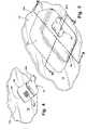
- FIG. 1is a side elevation and partial sectional of an interior rearview mirror assembly and accessory module in accordance with the present invention
- FIG. 2is a perspective view of a mirror mounting button on an interior surface of a window
- FIG. 3is a perspective view of an extension of the present invention as mounted on the button of FIG. 2 ;
- FIG. 4is a perspective view of a mirror mount on the extension of FIG. 3 ;
- FIG. 5is a perspective view of an accessory module body in accordance with the present invention on the extension of FIGS. 3 and 4 ;
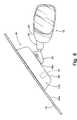
- FIG. 6is a side elevation of the accessory module of FIG. 5 , with an interior rearview mirror mounted to the mirror mount in accordance with the present invention
- FIG. 7is a sectional view taken along the line VII-VII in FIG. 5 , showing the accessory module as the module body is being moved along the extension;
- FIG. 8is a sectional view similar to FIG. 7 , showing the accessory module body mounted to the extension and loaded against the window;
- FIG. 9is a sectional view taken along the line IX-IX in FIG. 5 , showing an image sensor mounted within the accessory module;
- FIG. 10is a lower plan view of an accessory module of the present invention similar to the accessory module of FIGS. 5-9 ;
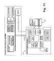
- FIG. 11is a block diagram of examples of accessories and functions of an accessory module in accordance with the present invention.
- FIGS. 12A and 12Bare side elevation and partial sectional views of an alternate embodiment of the accessory module of the present invention.
- FIGS. 12C and 12Dare front elevations of alternate embodiments of the accessory module and mirror assembly of FIGS. 12A and 12B , as looking forwardly with respect to the vehicle;
- FIG. 13is a perspective view of another alternate embodiment of an accessory module in accordance with the present invention.
- FIG. 14is a side elevation and partial sectional view of an alternate embodiment of an accessory module in accordance with the present invention, which is pivotable into engagement with the windshield;
- FIG. 15is a side elevation and partial sectional view of another alternate embodiment of an accessory module in accordance with the present invention, which is pivotable into engagement with the windshield;
- FIG. 16is a lower plan view of the accessory module of FIG. 15 ;
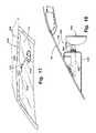
- FIG. 17is a perspective view of another alternate embodiment of an accessory module in accordance with the present invention which extends along a headliner of the vehicle;
- FIG. 18is a side sectional view of another alternate embodiment of an accessory module in accordance with the present invention.
- FIG. 19is a perspective view of a platform for mounting electrical circuit boards or other electrical connections suitable for use with the present invention.
- FIG. 20is a sectional view of another alternate embodiment of an accessory module in accordance with the present invention, with a removable circuit board;
- FIG. 21is a sectional view of another alternate embodiment of an accessory module in accordance with the present invention, with a removable circuit board;
- FIG. 22is a perspective view of another alternate embodiment of an accessory module in accordance with the present invention, with removable or interchangeable side pods;
- FIG. 23Ais a perspective view of another alternate embodiment of an accessory module in accordance with the present invention.
- FIG. 23Bis a sectional view of the accessory module taken along the line B-B in FIG. 23A ;
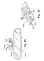
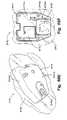
- FIGS. 24A and 24Bare perspective views of another accessory module in accordance with the present invention.
- FIGS. 25A-25Care perspective views of a mirror assembly mounted on the accessory module of FIGS. 24A and 24B ;
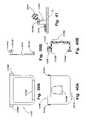
- FIGS. 26A-26Dare views of another accessory module in accordance with the present invention.
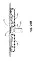
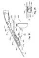
- FIG. 27is a side elevation and partial sectional view of another accessory module in accordance with the present invention.
- FIG. 28is a partial sectional view of an extender and fastener for the accessory module of FIG. 27 ;
- FIG. 29is a forward facing view of the accessory module and interior rearview mirror assembly of FIG. 27 ;
- FIG. 30is a perspective view of a printed circuit board suitable for use with the accessory module of FIGS. 27 and 29 ;
- FIG. 31is a top plan view of a vehicle incorporating the accessory module of FIGS. 27-30 ;
- FIG. 32is a side elevation of the vehicle of FIG. 31 ;
- FIG. 33is a side elevation of another accessory module in accordance with the present invention.
- FIG. 34is a side elevation of yet another accessory module in accordance with the present invention.
- FIG. 35Ais a plan view of a windshield button useful with an accessory module of the present invention.
- FIG. 35Bis a side elevation of the windshield button of FIG. 35A ;
- FIG. 36is a side elevation and partial sectional view of a mount extension of the present invention adapted to mount on the windshield button of FIGS. 35A and 35B ;
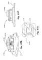
- FIGS. 37A and 37Bare a side view and a top view of another mounting button useful with an accessory module of the present invention.
- FIGS. 38A and 38Bare perspective views of a mount extension and button of an accessory module in accordance with the present invention.
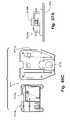
- FIG. 38Cis a side elevation and partial sectional view of the accessory module of FIGS. 38A and 38B ;
- FIG. 38Dis a sectional view taken along the line D-D in FIG. 38C ;
- FIGS. 39A and 39Bare a plan view and a side view of another mounting button useful with an accessory module of the present invention.
- FIGS. 40A and 40Bare a plan view and a side view of a mount extension of the present invention adapted to mount on the windshield button of FIGS. 39A and 39B ;
- FIG. 41is a partial sectional view of the retaining tab of the mount extension of FIGS. 40A and 40B as mounted on the button of FIGS. 39A and 39B ;
- FIG. 42Ais a plan view of another mounting button useful with an accessory module of the present invention.
- FIG. 42Bis a sectional view of a retaining tab or hook of the button taken along the line B-B in FIG. 42A ;
- FIGS. 43A and 43Bare a plan view and a side view of a mount extension of the present invention adapted to mount to the button of FIG. 42A ;
- FIG. 43Cis a sectional view taken along the line C-C in FIG. 43B ;
- FIG. 44is a side and partial sectional view of the retaining tab of the button of FIGS. 42A and 42B and the spring and hook of the mount extension of FIGS. 43A-C , as retained together;
- FIGS. 45A and 45Bare a plan view and a side view of a windshield mounting member with an extension at an end thereof having a mounting button for a mirror;
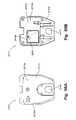
- FIGS. 46A-Care a plan view, a side view and an end view of a mounting button useful with an accessory module of the present invention
- FIGS. 47A and 47Bare an end view and a side view of a mount extension of the present invention adapted to mount to the mounting button of FIGS. 46A-C ;
- FIG. 48is a side elevation and partial sectional view of the retaining tabs or hooks of the mounting button of FIGS. 46A-C and the mount extension of FIGS. 47A and 47B , as retained together;
- FIGS. 49A and 49Bare a plan view and a side view of a mounting button useful with an accessory module of the present invention.
- FIGS. 50A and 50Bare a plan view and a side view of a mount extension of the present invention adapted to mount to the mounting button of FIGS. 49A and 49B ;
- FIG. 51is a plan view of a retainer for securing the mount extension of FIGS. 50A and 50B to the button of FIGS. 49A and 49B ;
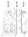
- FIGS. 52A and 52Bare a plan view and a side view of a mounting button arrangement for mounting an accessory module of the present invention to the windshield;
- FIG. 53is a side elevation and sectional view of a mount extension and accessory module of the present invention adapted for mounting to the button arrangement of FIGS. 52A and 52B ;
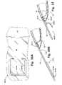
- FIGS. 54A and 54Bare a plan view and a side view of another mounting button arrangement for mounting an accessory module of the present invention to the windshield;
- FIG. 55is a side elevation and sectional view of a mount extension and accessory module of the present invention adapted for mounting to the button arrangement of FIGS. 54A and 54B ;
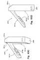
- FIGS. 56A and 56Bare a plan view and a side view of another mounting button arrangement for mounting an accessory module of the present invention to the windshield;
- FIG. 57is a side elevation and sectional view of a mounting tab for securing the accessory module to the button arrangement of FIGS. 56A and 56B ;
- FIGS. 58A-Dare perspective views of another accessory module in accordance with the present invention.
- FIG. 59is a perspective view of another accessory module of the present invention with an electrochromic mirror assembly mounted thereto;
- FIG. 60is a perspective view of another accessory module of the present invention with a prismatic mirror assembly mounted thereto;
- FIGS. 61A-Iare perspective views of other embodiments of an accessory module in accordance with the present invention.
- FIGS. 62A and 62Bare perspective views of an articulatable accessory module of the present invention, with an interior rearview mirror assembly attached thereto;
- FIGS. 63A-Dare perspective views of the articulatable accessory module of FIGS. 62A and 62B , with the interior rearview mirror assembly removed therefrom;
- FIGS. 64A and 64Bare perspective views of a base or mounting portion useful with the articulatable accessory module of FIGS. 62A , 62 B and 63 A-D;
- FIG. 64Cis a perspective view of a support or stiffening member useful with the articulatable accessory module of FIGS. 62A , 62 B and 63 A-D;
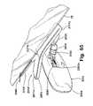
- FIG. 65is a perspective view of another articulatable accessory module in accordance with the present invention.
- FIGS. 66A-Care plan views of an accessory housing for an accessory module in accordance with the present invention.
- FIGS. 67A-Dare perspective, side and plan views of an accessory mounting module of an accessory module in accordance with the present invention.
- FIGS. 68A-Fare plan and perspective views of the accessory module and accessory housing and mounting module of FIGS. 66A-C and 67 A-D.
- an accessory module 10is mountable to and against a windshield 12 and is positioned generally between an interior rearview mirror assembly 14 and the windshield 12 (FIGS. 1 and 5 - 10 ).
- the accessory module 10is mounted toward and against an interior surface 12 a of the windshield in a manner which allows the body 10 a of the accessory module to move generally perpendicularly relative to the interior surface 12 a and to be loaded against or biased toward and to the windshield, as discussed in detail below, and such as disclosed in commonly assigned U.S. provisional applications, Ser. No. 60/381,314, filed May 17, 2002 by Schofield et al. for VEHICLE ACCESSORY MODULE; Ser. No.
- Accessory module 10may include one or more accessories, such as a rain sensor, a forward facing image sensor, a headlamp control, a temperature sensor, an antenna, a microphone, a speaker, a rearward facing image sensor, a security system, a display, indicators, user interface buttons, switches or the like, interior lights, GPS controls, a humidity sensor, a compass sensor, an electrochromic (EC) mirror control, a remote keyless entry control, a toll collection control, and/or any other accessories or controls of the vehicle, such as discussed below.
- accessoriessuch as a rain sensor, a forward facing image sensor, a headlamp control, a temperature sensor, an antenna, a microphone, a speaker, a rearward facing image sensor, a security system, a display, indicators, user interface buttons, switches or the like, interior lights, GPS controls, a humidity sensor, a compass sensor, an electrochromic (EC) mirror control, a remote keyless entry control, a toll collection control, and/or any other accessories or controls
- Accessory module 10is mounted to the vehicle windshield and includes an extender 16 , which is mounted to and extends from a mounting attachment 18 (such as a conventional mirror mounting button) at the windshield 12 .
- a mounting attachment 18such as a conventional mirror mounting button
- FIG. 2mounting button 18 is bonded or otherwise secured to interior surface 12 a of windshield 12 .
- a mounting portion 16 a of the extender 16is slid or otherwise moved into engagement with the button 18 .
- Extender 16includes a second mounting attachment or button 16 b ( FIG. 3 ) at its outer end for receiving a mirror mount 20 thereon ( FIG. 4 ).
- the button-on-button attachmentmay be similar to the attachments disclosed in U.S. Pat. No. 4,930,742, which is hereby incorporated herein by reference.
- the extender 16provides a rigid extension of a mounting button from the interior surface of the windshield for mounting the mirror assembly to the windshield.
- Extender 16provides a structural, load bearing connection between the attachment member 18 and the mount 20 of the support arm 22 ( FIG. 6 ) of the mirror 14 (or the mount of the mirror, as shown in FIG. 1 ) that is attachable to the accessory module.
- extender 16is preferably fabricated of a rigid, load bearing material, such as a metallic material or metal, such as a die cast metallic material, such as die cast zinc or die cast aluminum or the like.
- Extender 16may be a solid member, or may include channels or passageways therealong, which may include a wireway passage, such as for wirings to pass therethrough. The length of extender 16 is sufficient for the housing or body 10 a of the accessory module to slide over, but not so long as to create an excessive moment arm.
- the length of extender 16is selected to be approximately 0.5 inches to 3.5 inches, more preferably, approximately 0.75 inches to 2.5 inches, and, most preferably, approximately one to two inches.
- the extender 16also provides structural support for the body of the accessory module 10 .
- Extender 16is formed and adapted to mount to a particular mounting attachment member 18 at the windshield at one end of extender 16 .
- the opposite end of the extender 16is formed as a replication of the attachment member or button at the windshield of that particular vehicle.
- the extender of the present inventionthus provides a mounting attachment member 16 b for mounting a mirror mount thereto in the same manner as the mirror mount would mount to the attachment member 18 at the windshield.
- the extendermay have some or all of the plastics of the accessory module molded to the extender.
- the extendermay be die cast, such as a die cast metal (preferably die cast zinc or die cast aluminum) or otherwise formed, such as by molding of an engineering plastic, such as a filled nylon engineering plastic or the like, and may be formed as a structural skeleton member, without affecting the scope of the present invention.
- a coversuch as a plastic or polymeric cover, may be snapped or otherwise affixed or attached to the skeleton extender, without affecting the scope of the present invention.
- different extendersmay be used to adapt the accessory module for applications in different vehicles, such as vehicles manufactured by different vehicle manufacturers.
- the extendermay be die cast, such as in a metal die casting tool, which requires significantly less tooling costs than molds or the like, such that in order to adapt the accessory module for an application in another vehicle line or manufacturer (where the mounting attachment member or button may differ from one another), a new extender may be formed such that the mounting portion 16 a of the new extender accepts the button on the new vehicle and the second mounting attachment member 16 b matches or substantially replicates the button of the other vehicle, while the body 10 a of the module 10 remains the same or substantially the same.
- a common accessory module bodymay be sold to different vehicle manufacturers with an appropriate extender combined with the body. This provides substantially reduced costs for different applications, since new injection molding tools are not required to mold a new accessory module body for each application or vehicle line or vehicle manufacturer.
- the extendermay be formed or die cast to have a mounting portion 16 a for one vehicle (such as, for example, a vehicle manufactured by Ford Motor Company), and a mounting attachment member or button 16 b for another vehicle (such as, for example, a vehicle manufactured by General Motors Corporation or Volkswagen or Audi or BMW).
- a vehicle manufactured by Ford Motor Companysuch as, for example, a vehicle manufactured by Ford Motor Company
- a mounting attachment member or button 16 b for another vehiclesuch as, for example, a vehicle manufactured by General Motors Corporation or Volkswagen or Audi or BMW.
- the body 10 a of accessory module 10is slid over and along extender 16 until a portion of the body 10 a of accessory module 10 is engaged with and loaded toward the interior surface 12 a of windshield 12 .
- the mirror mount 20is mounted to the second attachment member 16 b at the end of extender 16 .
- Interior rearview mirror 14is pivotally mounted to a ball member 20 a extending from mirror mount 20 in a known manner. As shown in FIG. 6 , interior rearview mirror 14 may include a pivotable mounting arm 22 which pivotally receives ball member 20 a therein.
- interior rearview mirror 14may otherwise pivotally receive ball member 20 a in a socket (not shown) in the casing 24 of mirror 14 , or may otherwise mount to the end of mirror mount 20 or extender 16 , without affecting the scope of the present invention.
- the mirror and accessory mounting componentsprovide a breakaway type connection or mount, such as the types disclosed in U.S. Pat. Nos. 6,172,613; 6,087,953; 5,820,097; 5,377,949; and/or 5,330,149, which are hereby incorporated herein by reference.
- the body 10 a of accessory module 10includes a structural member 26 and a cover 28 , which together define a cavity 30 within accessory module 10 for mounting or receiving accessories therein.
- Structural member 26includes a plate portion 32 and a mounting portion 34 extending from plate portion 32 .
- the mounting portion 34 of structural member 26provides an opening or passageway 34 a for receiving extender 16 therethrough.
- mounting portion 34includes a plurality of teeth or projections 34 b extending from at least a portion of the mounting portion 34 a, while extender 16 likewise includes a plurality of teeth or projections 16 c extending outwardly therefrom.
- the corresponding teeth 34 b, 16 cengage one another as structural member 26 is pressed along extender 16 and toward windshield 12 to provide a ratcheting of body 10 a toward and against windshield 12 .
- the teethare angled to allow for movement of body 10 a along extender 16 toward the windshield, yet substantially preclude movement of body 10 a away from the windshield, such that accessory module 10 is retained tightly or snugly against the interior surface 12 a of windshield 12 .
- the teeth 34 bare positioned along a flexible tab or portion (not shown) of mounting portion 34 of structural member 26 to allow the tab to be flexed radially outward and away from extender 16 to allow for removal of body 10 a of accessory module 10 from the windshield for service, maintenance or replacement.
- the tab or other ratcheting or loading devicemay be accessible from the outer portion of the module (such as at the second button 16 b ) to allow for easy release of the ratcheting or loading device.
- the tabmay be flexed using a screwdriver or other tool inserted between the tab and extender 16 or via any other means to disengage the tab from the extender.
- structural member 26includes a retaining tab 36 ( FIGS. 7 and 8 ), which loads against the mounting button 18 to secure the joint between the module and the button to minimize vibration of the module.
- the retaining tab 36is biased toward the button, such that as the structural member 26 is loaded against the windshield, the retaining tab 36 loads and is biased against the mounting button 18 .
- the housing or structural membermay substantially encase the extender 16 , such that the housing or structural member closes over the slotted portion of the mounting portion 16 a of extender 16 , which allowed the extender to slide over the mounting button 18 on the windshield 12 . The extender 16 is thus substantially precluded from sliding off from the mounting button 18 .
- the cover 28 and structural member 26 of module 10may snap or otherwise be secured together to define the cavity 30 .
- the cover 28may define the plate along the interior surface of the windshield, such that the cover is attachable to the structural member at each end of a mounting portion of a structural member positioned or mounted around the extender.
- accessory module 10may include a sealing or cushioning member or strip 27 around the plate or cover portion of the module to cushion and/or seal the body 10 a of accessory module 10 at the interior surface 12 a of windshield 12 , in order to limit or substantially preclude vibration or rattle between the module and the windshield.
- the sealing or cushioning membermay comprise a soft material, such as an elastomeric material, such as a thermoplastic rubber material, and may be sufficiently resilient and dimensioned to provide a cushion between the module and the windshield and may take on the form of the windshield to further seal and cushion the accessory module at the windshield and to reduce noise and vibration of the accessory module.
- the cushioning membermay cushion the module against the windshield and may take on the form of the windshield such that the cushioning member functions to adapt the module to different angles or curvatures of the windshield as the module is moved toward and loaded against the windshield.
- accessory module 10may include an accessory 38 , such as a rain sensor (such as the type disclosed in commonly assigned U.S. Pat. Nos. 6,320,176; 6,353,392 and 6,313,454, which are hereby incorporated herein by reference), an image sensor (such as a video camera, such as a CMOS imaging array sensor, a CCD sensor or the like, such as the types disclosed in commonly assigned, U.S. Pat. Nos. 5,550,677; 6,097,023 and 5,796,094, which are hereby incorporated herein by reference), a temperature sensor (such as a contact temperature sensor for measuring the temperature at or of the windshield), an antenna, or any other sensor or device which is desirable to mount in tight or close engagement with the windshield.
- a rain sensorsuch as the type disclosed in commonly assigned U.S. Pat. Nos. 6,320,176; 6,353,392 and 6,313,454, which are hereby incorporated herein by reference
- an image sensorsuch as a video camera, such as a CMOS imaging array
- the accessory or sensor 38protrudes through an opening 32 a in the plate 32 and may include a biasing member or spring 40 which biases the accessory outward from accessory module 10 and toward windshield 12 . Accordingly, as the accessory module is loaded toward and against the windshield, the accessory 38 contacts the interior surface 12 a of the windshield 12 and is pressed against the surface via biasing member 40 , as shown in FIG. 8 . The accessory 38 is thus optically coupled or positively coupled to the windshield and retained in intimate contact with the windshield.
- the accessory 38may further include a sealing member (not shown) around a circumference of the accessory to engage the interior surface of the windshield and substantially seal the accessory to that portion of the interior surface of the windshield to protect that area of the windshield and the accessory from contaminants, such as dirt, dust, smoke, moisture or the like from affecting the performance of the accessory.
- a sealing member(not shown) around a circumference of the accessory to engage the interior surface of the windshield and substantially seal the accessory to that portion of the interior surface of the windshield to protect that area of the windshield and the accessory from contaminants, such as dirt, dust, smoke, moisture or the like from affecting the performance of the accessory.
- the accessory module of the present inventionmay alternately provide an accessory which is stood off from or spaced from the windshield.
- Such an arrangementmay be suitable for an antenna or the like, since the antenna reception may be interfered with by the windshield, which may comprise an electrically conductive windshield or the like.
- the accessory modulethus may provide a stand off antenna location to limit or substantially preclude such interference.
- accessory module 10may also or otherwise include an accessory 42 which is desirable to be oriented in a generally horizontal position or at a desired angle with respect to the windshield or horizontal.
- an accessorymay comprise a forward facing image sensor or camera (preferably a video camera, such as a CMOS imaging array sensor, a CCD sensor or the like, such as the types disclosed in commonly assigned, U.S. Pat. Nos. 5,550,677; 6,097,023 and 5,796,094, which are hereby incorporated herein by reference) or a compass sensor or the like.
- the forward facing image sensormay be useful in an optical rain sensor, such as the types disclosed in U.S. Pat. Nos.
- an adaptive cruise control systema sign recognition system and warning system, a night vision system, a pedestrian detection system, a vehicle classification identification system, a vehicle compatibility detection system, a pre-crash avoidance system, an emergency response image capture system, an environmental detection system (such as for detecting rain, fog, or the like), an ambient light level detection system, a vehicle relative position (such as for detecting the roll, yaw or the like of the vehicle), a compass calibration system (where the image captured from the image sensor is monitored to determine changes in direction of the vehicle to track the direction the vehicle is heading), a GPS system (where the image captured from the image sensor is monitored to determine the location of the vehicle when a signal from the GPS satellite(s) is interrupted), an electronic toll collection system, or any other system, without affecting the scope of the present invention.
- an environmental detection systemsuch as for detecting rain, fog, or the like
- an ambient light level detection systemsuch as for detecting the roll, yaw or the like of the vehicle
- a compass calibration system
- accessory module 10includes a mounting device 44 for such an accessory 42 , which is adjustable to set the accessory 42 to be horizontal or to be at the desired angle regardless of the angle of the windshield to which accessory module 10 is loaded.
- Mounting device 44provides a mounting platform or structure 44 a for securing accessory 42 within cavity 30 of body 10 a of accessory module 10 .
- Mounting device 44may be positioned at and partially through an opening 32 b of plate 32 to provide a passageway from accessory 42 to the windshield 12 .
- the mounting device 44may be adjustable relative to the structural plate or member 32 or to the housing 28 of accessory module 10 to align or orient the accessory 42 at the desired orientation.
- the mounting device 44may include a spherical member or ball joint (not shown) which allows for rotation or pivotal movement of the accessory 42 relative to housing 28 or plate 32 of accessory module 10 into the proper alignment or orientation (such as via rotation or pivotal movement of a portion of the platform 44 a ).
- Mounting device 44may include an outer sealing member 44 b which engages and seals against the interior surface 12 a of windshield 12 to provide a sealed chamber 44 c in which the accessory 42 is positioned.
- the ball jointmay also include a wiping seal along the spherical member to seal the chamber 44 c.
- the sealing memberslimit or substantially preclude dirt, dust, moisture, smoke or other contaminants from contacting or otherwise affecting the operation of accessory 42 of accessory module 10 .
- the accessory module of the present inventionmay include such a passageway along the interfacing surface against the windshield.
- the surface(s) of the accessory module facing the windshieldmay include heat dissipating elements, such as, for example, heat dissipaters, fins or the like.
- forced coolingmay be provided to the accessories or components of the accessory module, such as by a fan or the like (preferably, a low current fan, a solar powered fan or the like) to rapidly cool the accessories or components of the accessory module.
- the forced cooling elementmay be activated when the ignition of the vehicle is activated and then time out or deactivate a period of time following activation.
- the forced cooling elementthus functions to rapidly lower the temperature of the components or accessories, so that they may function optimally, even after prolonged soaking in extreme temperatures, such as while the vehicle has been parked, such as on a sunny day.
- a surface of the accessory module closest to the windshieldmay be treated, such as by a deposition, painting, film, adhesive coating or the like, to provide a reflecting characteristic to the module, so as to reflect infrared radiation or the like which the module may be exposed to at the windshield.
- the air passage and/or treatmentmay thus reduce the effects of sun loading or thermal loading on the accessory module.
- Accessory module 10may further include electrical connections for any electrical components within accessory module 10 or at or within mirror 14 .
- the mounting button 18 and/or second button 16 bmay include -electrical contacts which engage corresponding contacts at the mounting portion 16 a of extender 16 and/or mirror mount 20 , respectively, as the mounting portions are slid onto the buttons, such that electrical signals are provided to accessory module 10 and/or to mirror 14 via the contacts.
- the mounting button 18may be electrically connected to a power source of the vehicle or other electrical system or the like via an electrical connector or wiring harness or via contacting a conductor at the windshield, such as a conductor which is integral with the glass of the windshield or deposited on the interior surface of the windshield and which is connected to the vehicle power source or other electrical system of the vehicle.
- the mirror mount 20may then include an electrical connector or wiring which extends through an opening or passageway (not shown) in ball member 20 a and into the housing 24 of mirror 14 for connection to electrical components or circuitry within housing 24 .
- the electrical connectormay extend from the ball member and be sufficiently rigid to provide a snap connection or the like to a corresponding connector positioned within housing 24 as housing 24 is snapped or otherwise secured to ball member 20 a.
- the electrical connections to accessory module 10may be provided via other means, such as other sliding means, rotating contacts, screw or fasteners (such as tightening of a screw at the button to make an electrical contact or connection), or plug type connectors or contacts (such as an electrical contact of a spring loaded contact on the housing contacting a conductor at the windshield, such as a conductor which is integral with the glass of the windshield or deposited on the interior surface of the windshield), such that the accessory module makes its electrical connections as the body 10 a is ratcheted or loaded against the windshield.
- other meanssuch as other sliding means, rotating contacts, screw or fasteners (such as tightening of a screw at the button to make an electrical contact or connection), or plug type connectors or contacts (such as an electrical contact of a spring loaded contact on the housing contacting a conductor at the windshield, such as a conductor which is integral with the glass of the windshield or deposited on the interior surface of the windshield), such that the accessory module makes its electrical connections as the body 10 a is ratcheted or loaded against the
- the electrical connections to the mirror 14may be provided via other means, such as other sliding means, rotating contacts, screw or fasteners (such as tightening of a screw at the second button to make an electrical contact or connection), or plug type connectors or contacts, such that the mirror makes its electrical connections as it is mounted to the extender.
- the mounting button 18is provided on the windshield by the glass or windshield manufacturer, such that the windshield is shipped to the vehicle assembly plant with the button affixed thereon.
- the mirror manufacturermay then supply the accessory module, which includes the extender 16 and the body 10 a, along with the mount 20 and mirror 14 , as a single package to be mounted to the button 18 on the windshield at the vehicle assembly plant.
- the structural component 26 and housing 28may be only partially installed onto the extender 16 as shipped to the assembly plant, such that the extender may be secured to the button prior to the module body being moved or loaded toward and against the windshield.
- This last stepmay be performed at the vehicle assembly plant after the extender has been secured to the button and after any electrical components or connections have been provided at or near the module.
- the componentssuch as the image sensor, rain sensor and/or the like, may also be loaded against the windshield while the electrical connections to the vehicle electrical and/or control system may be simultaneously made.
- the extendermay be made and supplied as a separate part or component from the accessory module, without affecting the scope of the present invention.
- such an approachmay be less desirable, particularly with respect to the assembly plant operations.
- the accessory modulemay be provided with an electrical connector 70 ( FIG. 1 ), such as a wire and multi-pin connector or the like, extending from the accessory module for connecting to or plugging into a corresponding connector provided at a headliner or overhead console of the vehicle.
- an electrical connector 70FIG. 1
- an overhead console 71 of the vehiclemay extend toward the glass or window area, such that the overhead console may be at or close to or adjacent to the windshield, such as described in U.S. Pat. No. 6,445,287, and in U.S. patent application, Ser. No. 10/232,122, filed Aug. 30, 2002, now U.S. Pat. No.
- 6,975,215which are hereby incorporated herein by reference, and may provide a feed or outlet or socket or connector 72 for connecting the electrical connector 70 of the accessory module thereto.
- a connection arrangementallows the vehicle manufacturer to provide an outlet at the overhead console or headliner of the vehicle to provide electrical connection and/or communication between various accessories or systems or power source of the vehicle and the accessory module and/or interior rearview mirror assembly, whereby the vehicle manufacturer does not have to provide a cable or wiring harness extending down from the overhead console or headliner, as is typically done with conventional mirror assemblies and the like.
- the accessory module manufacturer and/or suppliermay thus provide the electrical connector or plug for extending to and connecting to the connector or outlet at the overhead console or headliner of the vehicle when the accessory module is mounted at the windshield of the vehicle.
- the accessory modulemay provide a high speed connection or different wires or cables as desired or required to power and/or drive the particular accessories and/or the like within the accessory module and/or the mirror assembly.
- such a connector or outlet or plug or socket or the likemay be provided at an overhead console or headliner of a vehicle for connection to an electrical wire or connector of other modules or components, such as a connector from an interior rearview mirror assembly or other type of accessory module or a separate windshield electronic module or the like.
- the connector at the overhead console or headlinermay provide for electrical connection to items or components or accessories of an accessory module, mirror assembly, windshield electronic module or the like which may share circuitry with other items or components or accessories of the vehicle, such as at the overhead console or headliner, and/or may provide for electrical power connection to the accessory module, mirror assembly, windshield electronic module or the like, and/or may provide for electrical communication to or control of items, components or accessories of the accessory module, mirror assembly, windshield electronic module or the like, such as from another accessory or system of the vehicle.
- the accessory modulemay include a rechargeable battery or power source, such as a rechargeable battery pack (such as shown generally at 74 in FIG. 6 ) or the like, which may provide power to the accessory or accessories of accessory module 10 and/or of mirror assembly 14 .
- the accessory modulemay then comprise a stand alone battery operated accessory module and may not require electrical connection to a vehicle power source or the like.
- the rechargeable battery packis attachable to and detachable from the accessory module to ease removal and recharging of the battery pack when the power supply of the battery pack is low.
- the accessory modulemay include contacts or connectors at a battery pack receiving portion of the module which electronically connect to the accessories or circuit board of the accessory module (similar electrical connections may electronically connect the accessory module to one or more accessories of the interior rearview mirror assembly).
- the contacts or connectorsmay contact or connect to corresponding contacts or connectors at the battery pack when the battery pack is attached to the battery pack receiving portion of the module, such that the rechargeable battery pack is electronically connected to the accessories or circuit board of the accessory module when attached to the accessory module.
- the rechargeable battery packmay include a plug or connector which is configured or adapted to plug into a vehicle power jack or outlet, such as a cigarette lighter type of outlet in the vehicle.
- the connector or plugmay be molded into or integrated into the battery pack, such that the battery pack may be removed or unplugged from the accessory module and plugged into the power outlet of the vehicle to recharge the battery or batteries of the rechargeable battery pack.
- the accessory module or battery packmay include a low power indicator which may be activated or illuminated or deactivated when the power level of the battery pack is reduced to a low level whereby the battery pack requires recharging.
- the batter packmay include a full charge indicator to indicate when the battery pack has completed the recharging process while plugged into the vehicle outlet.
- the battery packmay thus be recharged by the vehicle power source or battery, such as while the vehicle is being driven or even when the vehicle is not in operation.
- the recharging processmay result in a minimal draw of power from the vehicle, such that the battery pack may be recharged when the vehicle is not running, but may not significantly drain the battery or power supply of the vehicle.
- the battery packmay be unplugged from the vehicle outlet and plugged into or attached to the accessory module to provide power to the accessory or accessories of the accessory module and/or the mirror assembly.
- solar panels or the likemay be provided as a primary source for recharging of the battery pack, without affecting the scope of the present invention.
- a rechargeable battery pack in accordance with the present inventionmay be equally applicable for removably mounting to a mirror assembly or other module or console of the vehicle, in order to provide power to an accessory or accessories at or within the mirror assembly or other module or console of the vehicle.
- the rechargeable battery pack of the present inventionprovides a rechargeable battery or power source and may be suitable for use with a stand alone accessory module, console or mirror assembly, whereby the accessory module, console or mirror assembly may include various accessories, but may not require electrical connection to the vehicle power source or the like.
- a portion of the accessory modulemay include such a rechargeable battery pack and may be detachable from the rest of the accessory module, whereby the portion of the accessory module may be plugged into a power outlet of the vehicle to recharge the rechargeable battery pack contained or housed therein.
- the accessory module of the present inventionmay also include one or more antennae, which may be mounted as a separate component of the module, or may comprise conductive elements attached to or deposited directly onto the surfaces of the structural member or the cover plate of the accessory module.
- the antennamay be useful for a GPS system, a mobile/remote transaction system, such as a smart card system or an electronic toll collection system or the like, a remote keyless entry system, a communication system and/or any other system which may transmit a signal and/or receive a signal via an antenna.
- Accessory module 10may include any other accessories or components which it would be desirable to have in the general location of the interior rearview mirror. Because the accessory module is positioned at the interior rearview mirror and may be electrically coupled to the mirror, the accessory module may allow for decontenting of the mirror, such that many accessories, which may have been previously positioned at or within the mirror housing, are positioned at or within the accessory module.
- the mirrormay still include lights, electrochromic elements or the like, and may receive the appropriate electrical signals from the connection between the mirror and the mount at the extender.
- other electrical components and/or controls and/or circuitrymay be moved to the accessory module of the present invention.
- the accessory module of the present inventionmay include various accessories or features, such as shown in FIG. 11 .
- the accessory modulemay include one or more displays, such as a text display, an icon display, a display on demand type display, such as a video or touch screen interface display, a biometric imager, such as for fingerprint authentication or the like, an infrared sensor, such as a zonal temperature-sensor, such as suitable for an auto climate control, a forward facing image sensor, such as described above, a rearward facing image sensor (such as for biometric imaging (such as for face recognition, iris recognition or the like), seat height or position detection, drowsiness detection, safety/restraints object detection and position, emergency response image capture system, intrusion detection or the like), an electronic field sensor (such as the type disclosed in commonly assigned U.S.
- a speakerwhich may include a GPS module or system, a wireless communication module or system, an antenna for a GPS or phone or communication system or the like, a human/machine interface (HMI), a display, such as an LED display, dot matrix display, alpha numeric display, video display or the like, a microphone and/or microphone circuits, which may be operable for speech or voice recognition, noise reduction or noise cancellation), a speaker, a rechargeable battery pack, a humidity sensor, a compass sensor and/or compass control, an electrochromic (EC) control, a remote keyless entry sensor, a tire pressure monitoring system (TPMS), an electronic toll collection sensor, an emergency or roadside assistance system, an intelligent headlamp control and memory, user interface controls (such as buttons, switches or the like for controlling various accessories of the vehicle, such as a sunroof, a communication system, lamps, security systems, displays or the like) or any other accessories,
- HMIhuman/machine interface
- a displaysuch as an LED display, dot matrix display
- the accessory module and/or the mirror assemblymay include one or more other accessories, such as one or more electrical or electronic devices or accessories, such as antennas, including global positioning system (GPS) or cellular phone antennas, such as disclosed in U.S. Pat. No. 5,971,552, a communication module, such as disclosed in U.S. Pat. No. 5,798,688, a blind spot detection system, such as disclosed in U.S. Pat. Nos. 5,929,786 and/or 5,786,772, transmitters and/or receivers, such as a garage door opener device for actuating a garage door opening mechanism for opening a garage door or the like, such as disclosed in U.S. Pat. Nos.
- antennasincluding global positioning system (GPS) or cellular phone antennas, such as disclosed in U.S. Pat. No. 5,971,552
- a communication modulesuch as disclosed in U.S. Pat. No. 5,798,688, a blind spot detection system, such as disclosed in U.S. Pat. Nos. 5,929,
- a compasssuch as disclosed in U.S. Pat. Nos. 5,924,212; 4,862,594; 4,937,945; 5,131,154; 5,255,442; and/or 5,632,092, a tire pressure monitoring system (TPMS), such as the types disclosed in U.S. Pat. Nos. 6,294,989; 6,445,287; and/or 6,472,979, and in U.S. patent applications, Ser. No. 10/232,122, filed Aug. 30, 2002, now U.S. Pat. No. 6,975,215; and Ser. No. 10/279,059, filed Oct. 23, 2002, now U.S. Pat. No.
- TPMStire pressure monitoring system
- the accessory or accessoriesmay be positioned at or within the accessory module housing and/or the mirror casing and may be included on or integrated in a printed circuit board positioned within the respective housing or casing, without affecting the scope of the present invention.
- the accessories or components of the accessory modulemay be connected to the vehicle electronic or communication systems and may be connected via various protocols or nodes, such as Bluetooth, SCP, UBP, J1850, CAN J2284, Fire Wire 1394, MOST, LIN and/or the like, depending on the particular application of the accessory module of the present invention.
- the accessory modulemay be electronically integrated with the vehicle electrical and/or control systems.
- the accessory modulemay connect to a sunroof control, a rain sensor control, a mass motion sensor, a roof lighting control, a microphone/cell phone control, a climate control, an electrochromic mirror reflective element or cell control and/or the like.
- the accessory modulemay provide an output to the vehicle system or systems over a communication bus, such as a high beam activation level (which may be dependent on the module interface type, such as duty cycle, active/inactive, percent illumination, etc.), an intelligent headlamp control enabled/fault indicator status, a rain sensor status, a compass status, an ambient light level status (which may be an interior or exterior lighting status), an exterior condition status, an autolamp status, a sunload status and/or the like.
- a high beam activation levelwhich may be dependent on the module interface type, such as duty cycle, active/inactive, percent illumination, etc.
- an intelligent headlamp control enabled/fault indicator statuse.g., a rain sensor status, a compass status, an ambient light level status (which may be an interior or exterior lighting status), an exterior condition status, an autolamp status, a sunload status and/or the like.
- the accessory modulemay also receive various inputs over the communication bus or communication line, such as an intelligent headlamp control enabled/disabled status, a transmission status (such as park, reverse, neutral, drive, low or other gear settings), a headlamp status, a vehicle speed, a steering wheel angle, a turn signal status, and/or the like.
- the accessory modulemay be in electrical communication with the interior rearview mirror assembly, such as for controlling an electrochromic cell of the mirror and/or a microphone of the mirror and/or the like, and may be in communication with a telematics system of the vehicle, such as to provide a signal from a microphone or speaker at the accessory module and/or the interior rearview mirror assembly.
- the accessory modulemay include a vehicle connector for connecting to a wire or cable of the vehicle, which may provide power and electrical communication to the accessory module, such as via a communication bus or the like.
- the accessory modulemay include a rechargeable battery pack, such as described above, and may thus comprise a stand alone accessory module and thus may not require electrical connection to the vehicle wiring and/or controls.
- Accessory module 10may also include user interface controls, such as buttons, switches or the like, displays, indicators, microphones, speakers or the like. Some of these may be provided at or along a display or interface area above the mirror, such as shown at display or interface area 46 in FIGS. 12A-D and 13 .
- accessory module 10may include an extension (such as shown in FIGS. 59-65 ) which extends over or under the mirror 14 to provide easier or enhanced access and viewing of various user interface controls or displays or the like, without affecting the scope of the present invention.
- display or interface portion or area 46may comprise an upwardly extending display or user interface portion and may be extendable and retractable relative to the mounting button area of the accessory module, such that the extension may be moved upward to provide clearance over the mirror (as shown in FIGS. 12A , 12 B and 13 ) or such that the extension may be moved upward toward the headliner of the vehicle, depending on the application of the accessory module of the present invention.
- an accessory module 110 in accordance with the present inventionis loaded toward and against the interior surface 12 a of the windshield 12 via pivotal movement of the accessory module 110 about a pivot axis or joint 111 at the headliner 113 of the vehicle.
- the accessory module 110includes a mirror mount 120 which extends from a lower portion of the module for mounting a mirror assembly 114 thereto.
- Accessory module 110may include any and/or all of the accessories or components discussed above with respect to accessory module 10 and may provide for electrical connection to the electrical components or accessories via electrical connection when the module is pivotably mounted at the headliner and/or when the module is pivoted toward and against the windshield to load the module against the windshield, such as via electrical contacts or plugs or the like, as discussed above.
- the accessory module 110may be loaded toward and against the windshield via a ratcheting of the module as it is pivoted toward engagement with the windshield or via other means for loading and retaining the module at the windshield.
- an accessory module 210may be pivotally mounted at the headliner 213 of the vehicle, such as at a pivot axis or joint 211 , and may include an expandable area 228 a of the housing 228 to provide a continuous module housing 228 while accommodating flexing of the module housing as the module is pivoted toward or away from the windshield.
- some of the interface controls, displays, lights, indicators and/or the likemay be positioned at a control console at and along the headliner of the vehicle, without affecting the scope of the present invention.
- the accessory module of the present inventionmay be an extension of a header portion of the vehicle and/or a header console of the vehicle, such as to provide a viewing area or display visible through the windshield from outside the vehicle, such as described in commonly assigned, U.S. patent application, Ser. No. 09/710,016, filed Nov. 10, 2000 by Schofield et al. for TIRE INFLATION ASSISTANCE MONITORING SYSTEM, now U.S. Pat. No. 6,445,287, which is hereby incorporated herein by reference.
- the module or lobe extending down from the header portion or consolemay be spring mounted or otherwise loaded or biased toward the windshield and may include a cushioning or sealing member to cushion the module against the windshield.
- the header portion or consolemay be installed at the roof or header of the vehicle (such as before the windshield is installed to the vehicle) and may include a lobe or module which may be movable forwardly with respect to the vehicle to move and load the module against the interior surface of the windshield after the windshield is installed in the vehicle.
- the modulemay be spring loaded to move and load the module toward and against the windshield, or may be ratcheted forward or otherwise moved toward the windshield to move and load the module toward and against the windshield of the vehicle.
- the modulemay then be retractable or movable away from the windshield to facilitate access, service, maintenance or replacement of the accessory module.
- an accessory module 310 in accordance with the present inventionmay comprise a housing 328 which extends at least partially across the headliner 313 of the vehicle and provides a mount 320 for mounting a mirror assembly 314 thereto.
- the accessory module 310extends entirely across the headliner between the A-pillars of the vehicle to provide a continuous module along and above the upper edge of the windshield.
- the accessory module 310may include one or more sun visors 315 , which may fold down or be pulled down and unrolled from within the accessory module 310 to provide shielding of the sun from the driver's or passenger's eyes.
- the accessory module 310may include any and/or all of the accessories or components discussed above with respect to accessory module 10 and may provide for electrical connection to the electrical components or accessories via electrical connection when the module is mounted along the headliner (such as via screws, snaps, or other fasteners) and against the windshield (whereby the module is preferably loaded against the windshield), such as via electrical contacts or plugs or the like, similar to those discussed above.
- an accessory module 410may be biased or spring loaded against the interior surface 12 a of the windshield via a biasing member or spring 429 along the mounting arm 422 .
- Spring 429is positioned between a raised portion or stop 422 a along mounting arm 422 of mirror 414 and a cover 428 of accessory module 410 .
- the accessory module 410may include accessories, displays, user interface controls and/or the like, as discussed above with respect to accessory module 10 .
- an accessory module in accordance with the present inventionmay include a plate or platform 50 , which may further include a main board or power bus 52 mounted or affixed thereto.
- the platform 50may then include one or more electronic sub-boards 54 , which may be attached to the platform 50 as desired, depending on the particular application of the accessory module and on the desired features or accessories of the module.
- an accessory module 510may include a removable, plug-in module 552 , which may be installed in or removed from the module depending on the application of the module and the desired functions and features of the module.
- the accessory module 510may include a removable panel 528 a at housing 528 to facilitate access to the plug-in module 552 .
- a plug-in module or card 562may be retained in connection with an electrical connector via a retention clip 564 , as shown in FIG. 21 .
- the mirror mount 520may connect to an exterior surface of housing 528 of accessory module 510 .
- an accessory module 610may include a center module 610 a mounted to or at the windshield in a manner according to the present invention.
- the center module 610 amay provide a connector 668 along one or both sides of the center module for connection of one or more side pod modules 610 b, 610 c.
- the center module 610 a and/or the side pod modules 610 b, 610 cmay include various accessories, displays, controls, indicators and/or the like, such as discussed above with respect to accessory module 10 .
- the electrical connections to the side pod modules 610 b, 610 cmay be made as the side modules are snapped or otherwise attached or mounted to center module 610 a, such as via electrical connectors 668 , 669 .
- an accessory module 710may mount to the windshield 12 and include an opening or passageway 734 a for fitting the accessory module around a mounting button 718 , mount 720 and mounting arm 722 of a mirror 714 .
- the accessory module 710may include a structural mounting portion or member 726 and a cover 728 , which define a cavity 730 for housing various accessories or the like.
- the accessoriesmay include any accessories, controls, indicators, displays and/or the like as discussed above.
- an accessory module 810is mountable to a mounting button (not shown) at a windshield of a vehicle and provides a second mounting button 816 a for mounting a mirror mount 820 and mirror 814 to accessory module 810 .
- the second mounting button 816 ais positioned within a pocket or recessed area, where the pocket allows sufficient clearance for the mirror mount 820 to fit in and slide onto the button 816 a.
- the accessory modulemay extend upward and over the mirror 814 , as can be seen in FIGS. 25B and 25C , to provide access to one or more user interface controls or buttons 811 at an upper end of the accessory module 810 .
- the accessory modulemay provide buttons 811 , such as for actuating a garage door opener device or system of the vehicle or accessory module for actuating a garage door opener mechanism for opening a garage door or the like, such as the types described in U.S. Pat. Nos. 6,396,408; 6,362,771; 5,798,688 and 5,479,155, which are hereby incorporated herein by reference, such as the type available from Johnson Controls, Inc. of Madison, Mich., under the name HOMELINK®.
- the accessory module 810includes a mounting portion 810 a and an upper extension 810 b which extends over the mirror 814 .
- the angle of the upper portion 810 b relative to the lower portion 810 ais selected according to the angle of the windshield of the targeted vehicle, such that the buttons are directed generally parallel to the floor of the vehicle when the accessory module is mounted to the windshield.
- the upper portionmay be pivotable so that the upper portion may be canted toward the driver and secured in such position, or the upper portion may desirably be rigidly canted toward the driver (such as approximately 10-35 degrees, and preferably 15-25 degrees), to provide enhanced visibility and access to the buttons by the driver of the vehicle.
- the upper portion 810 b of the accessory modulemay include an information display, such as a compass display (not shown).
- an information displaysuch as a compass display (not shown).
- all of the compass circuitry, including the vacuum fluorescent display and the compass sensors,may be created on one circuit board, thus allowing economy of parts fabrication.
- the orientation of the compass sensing elementsuch as a magnetoresistive sensor, such as described in U.S. Pat. No. 5,802,727, and U.S. patent application, Ser. No. 09/540,702, filed Mar. 31, 2000 by Schierbeek et al. for VEHICLE COMPASS COMPENSATION, now U.S. Pat. No.
- the compass and/or compass displaymay be of the types disclosed in U.S. provisional application, Ser. No. 60/420,010, filed Oct. 21, 2002 for INTERIOR REARVIEW MIRROR WITH COMPASS, which is hereby incorporated herein by reference.
- the accessory module of the present inventionmay be mounted on the button at the windshield during a first operation at the vehicle assembly plant.
- the module mounting membermay be adapted to be attached to the button (preferably in a detachable way), and may include a mechanical fastener, such as a screw or other fastener, or a snap type connection or the like to secure the mounting member the button.
- the second button on the accessory moduleis a replicate of the button on the windshield, the mirror may mount on the second button during a second operation.
- the accessory modulemay be provided to a vehicle assembly plant with the mirror assembly preattached to the module. The entire assembly may thus be adapted to be readily mounted to the attachment member or button at the windshield in a single operation at the vehicle assembly plant.
- the accessory module of the present inventionpreferably provides visual and mechanical guides or cues to facilitate the mounting operation as the accessory module is mounted to the windshield.
- an accessory module 910is mountable at and/or loadable against an interior surface of a vehicle windshield, such as in a similar manner as discussed above with accessory module 10 .
- Accessory module 910is substantially similar to accessory module 10 discussed above, such that a detailed discussion of the features and characteristics of the accessory module will not be repeated herein.
- the rearview mirror assembly 914which is mounted to the mounting portion 920 at accessory module 910 , may include a microphone 915 .
- Microphone 915may be mounted at an upper portion of the mirror assembly 914 and beneath an upper, curved portion 910 b of the body 910 a of accessory module 910 .
- the microphone 915may be of the type disclosed in commonly assigned, U.S. Pat. Nos. 6,243,003 and 6,278,377, and/or U.S. patent application, Ser. No. 09/466,010, filed Dec. 17, 1999 by DeLine et al. for INTERIOR REARVIEW MIRROR SOUND PROCESSING SYSTEM, now U.S. Pat. No. 6,420,975, and/or U.S. provisional applications, Ser. No. 60/415,233, filed Oct. 1, 2002 by DeBoer et al. for INTERIOR REARVIEW MIRROR ASSEMBLY WITH ACCESSORY, Ser. No. 60/429,360, filed Nov. 26, 2002 by Weller for MICROPHONE SYSTEM FOR VEHICLE, which are all hereby incorporated herein by reference.
- a stand-alone accessory module 1010is mounted to an interior-surface 12 a of a windshield 12 of a vehicle and includes an extender 1016 , which is mounted to and extends from a mounting attachment 1018 (such as a conventional mirror mounting button) at the windshield 12 .
- a mounting portion of the extender 1016may be slid or otherwise moved into engagement with the button 1018 , as discussed above with respect to accessory module 10 .
- accessory module 10may detachably attach (and preferably breakaway if impacted, such as in an accident) to button 1018 (such as using a fastenerless attachment element, such as a top clip attachment, such as described in U.S. Pat. No. 5,576,687, which is hereby incorporated herein by reference) or may be secured thereto using a screw or similar fastener.
- Extender 1016may comprise a die-cast metallic member or a plastic molded member or the like, without affecting the scope of the present invention.
- extender 1016may include a channel or passageway 1017 , such as a cylindrical passageway and/or threaded passageway, extending lengthwise through the extender, such that a threaded fastener or screw 1015 may be threaded through the extender to an opening or indentation in the button to retain or secure the extender to the button.
- the screwmay be countersunk into the extender to provide a generally flat surface at the opposite end from the button end.
- the channelmay include a larger diameter passageway 1017 a (large enough for the head of the fastener to be driven into to countersink the head of the fastener within the extender), which may extend substantially into the extender 1016 to allow the fastener 1015 to be partially threaded onto a threaded portion 1017 b of the passageway, yet still be substantially within the countersunk portion. Because the fastener 1015 is initially positioned at least partially within the extender, a drive tool may be easily aligned with and engaged with the head of the fastener for driving the fastener into its securing position.
- the accessory moduleincluding the extender and screw, may thus be provided to the vehicle assembly plant, whereby the screw or fastener may be easily driven into and/or against the mounting button 1018 by an operator at the vehicle assembly plant. The operator may then slide or otherwise position the extender onto the button and drive the screw or fastener into place to secure the extender to the button and windshield.
- Extender 1016includes a second mounting attachment or button at its outer end for receiving a mirror mount 1020 thereon ( FIG. 27 ).
- the button-on-button attachmentmay be similar to the attachments disclosed in U.S. Pat. No. 4,930,742, which is hereby incorporated herein by reference.
- the extenderprovides a rigid extension of a mounting button from the interior surface of the windshield for mounting (and supporting) an interior rearview mirror assembly 1014 to the windshield 12 .
- the interior rearview mirror assemblymay comprise a prismatic mirror assembly or an electrochromic mirror assembly or the like, without affecting the scope of the present invention, and with the interior rearview mirror assembly preferably forming a detachable and/or breakaway attachment to the outer end of extender 1016 of accessory module 1010 .
- extender 1016provides a structural, load bearing connection between the attachment member 1018 and the mount 1020 of a support arm 1022 of the interior rearview mirror assembly 1014 (or the mount of the mirror, such as shown in FIG. 1 ) that is attachable to accessory module 1010 .
- extender 1016is preferably fabricated of a rigid, load bearing material, such as a metallic material or metal, such as a die cast metallic material, such as die cast zinc or die cast aluminum or the like.
- Extender 1016may comprise a solid member, or may include channels or passageways therealong, which may include a wireway passage, such as for wirings to pass therethrough or a channel-way to accommodate a screw type fastener, such as described above.
- extender 1016is sufficient for the housing or body 1011 of accessory module 1010 to slide over/secure to, but not so long as to create an excessive moment arm or to unduly move the reflective element of the interior rearview mirror assembly that attaches to the accessory module toward and close to the driver of the vehicle. Extender 1016 also provides structural support for the body of the accessory module and for any accessories contained therein or attached thereto.
- extender 1016is formed and adapted to mount to a particular mounting attachment member 1018 at the windshield at one end of extender 1016 .
- the opposite end of the extenderis typically formed as a replication of the attachment member or button at the windshield of that particular vehicle (however, as previously indicated, the opposite end of the extender may be different from the button that the extender is mounted to so as to allow aftermarket installation of an accessory module that has a mirror mounting end for a mirror that anticipates a different button).
- extender 1016may have some or all of the plastics of the accessory module molded to the extender, such as by integral molding.
- the extendermay be die cast, such as a die cast metal (preferably die cast zinc or die cast aluminum) or otherwise formed, such as by molding of an engineering plastic, such as a filled nylon engineering plastic or the like, and may be formed as a structural skeleton member.
- Extender 1016may be a solid construction or a hollow construction, such as a solid or hollow slug, and is preferably of limited length or extension so as to both facilitate ease of attachment to the mirror button by a vehicle assembly line operator (and where a screw or other fastener is used, the driving of the screw by the operator) and to minimize the further extension of the mirror reflector of the mirror assembly toward the driver when the mirror assembly is mounted to the extender.
- the extensionis no more than approximately two inches long, more preferably, no more than approximately 1.25 inches long, and most preferably, no more than approximately 0.75 inches long, to provide a sufficient space between the mirror mount 1020 and the mounting button 1018 for housing or body 1011 .
- a coversuch as a plastic or polymeric cover, may then be snapped or otherwise affixed or attached to the skeleton extender, without affecting the scope of the present invention.
- Housing or body 1011 of accessory module 1010includes a base portion or fixed portion 1011 a and an upper portion or movable portion or head portion 1011 b extending from the base portion, as shown in FIG. 27 .
- Base portion 1011 amay be integrally molded with or onto extender 1016 or may snap or otherwise be secured to extender 1016 , such as in the manners described above.
- body 1011can be formed in a separate molding operation and can snap onto extender 1016 as desired, without affecting the scope of the present invention.
- Body 1011includes a mounting portion 1011 c for mounting head portion 1011 b to base portion 1011 a, and preferably for movably or pivotably mounting head portion 1011 b to base portion 1011 a.
- a head portionmay also or otherwise be mounted at a lower end of the base portion and positioned below the base portion and interior rearview mirror assembly, without affecting the scope of the present invention.
- the mounting portion 1011 c of housing 1011preferably allows for different types of head portions to be mounted to a standard or common base portion.
- the different headsmay be tooled up or manufactured with different accessories associated therewith.
- a head portion with the display optionmay be mounted to the base portion of the accessory module
- a garage door opener optiona head portion with such a garage door opener option may be mounted to the base portion.
- other accessories or optionsmay be incorporated into accessory module 1010 , without affecting the scope of the present invention.
- the base portionthus may be a common part, while the head portion may be selected to match a desired function or option of the vehicle and may be mounted to the base portion.
- all of the electronicssuch as electronic circuitry for a compass system and display, a temperature display, a garage door opener device or system and associated buttons, a user input device or buttons, such as for a telematics system or the like, a microphone and/or any other desired system or systems or accessory or accessories may be positioned at or within the head portion, such that the accessory module may comprise the same base portion irrespective of the selected option or options or function or functions of the head portion.
- the different modules with different featuresmay mount to the mounting portion 1011 c and optionally may be movably or adjustably mounted thereto.
- the mounting portion 1011 cmay include pivot or swivel elements, such as a ring or partial ring of detents or indents or a ball joint or other type of swivel joint connection, which allows head portion 1011 b to pivot or swivel relative to base portion 1011 a, such as side to side and about a generally vertical pivot axis when the accessory module is mounted to the vehicle, so as to direct the head portion 1011 b toward the driver, and/or up and down and about a generally horizontal pivot axis when the accessory module is mounted to the vehicle, so as to adjust a level at which the head portion is positioned.
- pivot or swivel elementssuch as a ring or partial ring of detents or indents or a ball joint or other type of swivel joint connection
- the module mounting portionmay have a preset angle, such that the head portion may snap onto the base portion and be generally fixed (such as at a preset angle) relative to the base portion, without affecting the scope of the present invention.
- the detent ringallows for the head (or tail) portion to pivot or swivel and to click or snap or lock into place at one or more particular angles (such as at approximately six degrees downward and approximately twelve degrees toward the driver).
- the detent ringmay include several detents, such that the head portion may be adjusted to one of several positions or orientations relative to the base portion.
- the head portionmay be adjusted to an appropriate position when installed and then generally fixed or locked relative to the base portion, or may be adjustably mounted such that the head portion may be later adjusted by the driver of the vehicle if desired.
- the swivel or pivot mounting elementsmay be molded into the housing portions of the accessory module, or may be attached thereto, without affecting the scope of the present invention.
- the mounting portion 1011 cmay provide a swivel joint which may include a generally spherical ball shaped member which includes a plurality of dimples or indentations on its surface (such as similar to the surface of a golf ball), such that a corresponding portion of the mounting portion may at least partially receive the ball shaped member and engage an appropriate one or ones of the dimples or indentations to substantially secure or fix the head portion in a desired orientation relative to the base portion of the accessory module.
- a swivel jointwhich may include a generally spherical ball shaped member which includes a plurality of dimples or indentations on its surface (such as similar to the surface of a golf ball), such that a corresponding portion of the mounting portion may at least partially receive the ball shaped member and engage an appropriate one or ones of the dimples or indentations to substantially secure or fix the head portion in a desired orientation relative to the base portion of the accessory module.
- the head portionmay be adjustable via pivotal movement of the head portion relative to a horizontal direction or the x and y axes of the vehicle and/or relative to a vertical direction, such as left and right and/or up and down, to horizontally and/or vertically adjust the orientation of the head portion at various angles relative to the base portion.
- the head portion 1011 b of accessory module 1010may be angled or canted to a desired orientation with respect to the windshield and with respect to a location corresponding to a typical location of the head of the driver of the vehicle.
- the head portion of the accessory moduleis pivotable to be canted or positioned at an angle A with respect to the longitudinal axis 1009 ( FIG. 31 ) of the vehicle which is approximately 8-18 degrees toward the driver of the vehicle, more preferably, approximately 10-15 degrees, and most preferably, approximately 11-13 degrees.
- the head portion 1011 bmay be angled downwardly toward the driver's head at an angle B with respect to a generally horizontal plane 1007 ( FIG. 32 ).
- the head portionmay be angled downwardly toward the driver's head location at an angle greater than approximately 1 degree and less than approximately 15 degrees, and more preferably, greater than approximately 5 degrees and less than approximately 10 degrees downward.
- Accessory module 1010may include various accessories within base portion 1011 a and/or head portion 1011 b.
- base portion 1011 a of accessory module 1010includes a forward facing video image sensor or system 1062 .
- the image sensor or system 1062may include an intelligent rain sensor (such as the type disclosed in commonly assigned U.S. Pat. Nos. 6,320,176; 6,353,392; 6,313,454; 6,341,523; and 6,250,148; and/or in U.S. patent applications, Ser. No. 10/023,162, filed Dec. 17, 2001 by Lynam for RAIN SENSOR MOUNT FOR USE IN A VEHICLE, now U.S. Pat. No. 6,516,664; and Ser. No.
- the image sensormay be implemented with any type of vehicle vision system or the like, such as a vision or imaging system utilizing principles disclosed in U.S. Pat. Nos. 6,396,397 and 6,201,642, and/or U.S. patent applications, Ser. No. 10/010,862, filed Dec. 6, 2001, now U.S. Pat. No. 6,757,109; and Ser. No. 09/199,907, filed Nov. 25, 1998, now U.S. Pat. No. 6,717,610, which are hereby incorporated herein by reference.
- the accessory module of the present inventionmay provide for positive perpendicular coupling of the base portion of the accessory module to the windshield to optically couple such sensors toward and against the windshield if desired.
- Base portion 1011 a of the illustrated embodiment of FIG. 27further may include a short-range radio frequency (RF) transceiver 1064 for communication with other vehicle electronic or communication systems and may communicate to such systems via various protocols or nodes, such as Bluetooth, SCP, UBP, J1850, CAN J2284, Fire Wire 1394, MOST, LIN and/or the like, depending on the particular application of the accessory module of the present invention.
- the accessory modulemay be electronically integrated with the vehicle electrical and/or control systems.
- the accessory modulemay connect to a sunroof control, rain sensor control, mass motion sensor, roof lighting control, microphone/cell phone control, climate control, or the like, without affecting the scope of the present invention.
- head portion 1011 bmay include a microphone or microphone array 1066 for receiving audio or voice signals from within the cabin of the vehicle.
- the microphone or microphone arraymay be part of a communication system, such as disclosed in U.S. Pat. Nos. 6,243,003 and 6,278,377, and in U.S. patent application, Ser. No. 09/466,010, filed Dec. 17, 1999 by DeLine et al. for INTERIOR REARVIEW MIRROR SOUND PROCESSING SYSTEM, now U.S. Pat. No. 6,420,975, which are hereby incorporated herein by reference.
- microphone 1066is mounted or positioned at an underside of head portion 1011 b, which shelters the microphone from direct moisture intrusion, such that the microphone or microphone array is sheltered from direct exposure to debris or rain or the like, such as when the accessory module is mounted in a convertible.
- Head portion 1011 bpreferably includes a single circuit element 1052 ( FIGS. 27 and 30 ), such as a printed circuit board (PCB) mounted at least partially within head portion 1011 b.
- printed circuit board 1052may include a display element 1054 along or partially along an edge of the board and may include one or more user-actuatable controls or buttons 1056 near or adjacent to the display element 1054 .
- the display elementmay be any type of display, such as a vacuum fluorescent (VF) display, a light emitting diode (LED) display, an electroluminescent (EL) display, a liquid crystal (LCD) display, a video screen display or the like, and may be for displaying various information (as discrete characters, icons or the like, or in a multi-pixel manner) to the driver of the vehicle, such as compass heading information, passenger side inflatable restraint (PSIR) information, tire pressure status, and/or the like.
- VFvacuum fluorescent
- LEDlight emitting diode
- ELelectroluminescent
- LCDliquid crystal
- video screen display or the likea video screen display or the like
- various informationas discrete characters, icons or the like, or in a multi-pixel manner
- PSIRpassenger side inflatable restraint
- buttonsmay be for actuating or controlling various accessories or controls or components associated with the vehicle, such as for a compass calibration setting or zone setting, a telematics actuation, a garage door opener device, an electronic toll control (such as disclosed in U.S. patent application, Ser. No. 09/793,002, filed Feb. 26, 2001 by Schofield et al. for VIDEO MIRROR SYSTEMS INCORPORATING AN ACCESSORY MODULE, now U.S. Pat. No. 6,690,268, which is hereby incorporated herein by reference), and/or the like, or may be for switching the display between various functions or modes, without affecting the scope of the present invention.
- various accessories or controls or components associated with the vehiclesuch as for a compass calibration setting or zone setting, a telematics actuation, a garage door opener device, an electronic toll control (such as disclosed in U.S. patent application, Ser. No. 09/793,002, filed Feb. 26, 2001 by Schofield et
- the head portion 1011 bmay include appropriate openings along its face 1011 d, such that the display element 1054 is visible through one opening, while the buttons or controls may partially protrude through other corresponding openings when an appropriate circuit board is installed within the head portion. This allows for the manufacturer of the printed circuit board to easily place the board in the head portion of the accessory module of the present invention.
- the printed circuit board 1052may include other electronic components 1058 , such as integrated circuits, resistors, capacitors, diodes and/or the like.
- the printed circuit board or elementmay also include one or more accessories, such as a compass sensor 1060 for a compass system of the vehicle, such as a compass system of the type disclosed in commonly assigned U.S. Pat. No. 5,255,442, and U.S. patent application, Ser. No. 09/540,702, filed Mar. 31, 2000 by Schierbeek et al. for VEHICLE COMPASS COMPENSATION, now U.S. Pat. No. 6,513,252, which are hereby incorporated herein by reference.
- the compass sensormay be a magneto-resistive sensor, a magneto-capacitive sensor, a magneto-inductive sensor, or a flux-gate sensor or the like, without affecting the scope of the present invention.
- the head portionis not user movable or adjustable by the driver or occupant of the vehicle when installed in the vehicle, so that the alignment of the compass sensor is predictable relative to the x and y axes of the vehicle and generally invariant over the driving use of the vehicle.
- the head portionmay be set relative to the base portion at a generally fixed or preset angle, but preferably is a fixed mount that may not be adjustable by a user, such as a driver or occupant of the vehicle, in such an application.
- the head portionthus may be generally fixedly positioned at the or relative to the base portion when the accessory module is mounted at the vehicle, and thus may be non-adjustable by a driver or occupant of the vehicle during normal use of the vehicle and/or the accessory module.
- the accessory module of the present inventionmay include a network bus, such as a CAN bus or a LIN bus, such as disclosed in U.S. Pat. No. 6,291,905, which is hereby incorporated herein by reference.
- the network busmay be operable to communicate with other systems of the vehicle, such as with accessories or elements of the interior rearview mirror assembly.
- the interior rearview mirror assemblymay include an electrochromic rearview mirror, preferably utilizing a solid polymer matrix electrochromic medium, such as described in U.S. Pat. No. 5,910,854, which is hereby incorporated herein by reference.
- the network bus of the accessory modulemay then be in communication with the reversing system of the vehicle, such that the accessory module knows when the vehicle is shifted into reverse.
- the busmay then be operable to communicate this to the electrochromic rearview mirror assembly to disable the electrochromic dimming of the mirror when the vehicle is in reverse, as is desired and known in the art.
- the accessory module of the present inventionthus may provide for hard wiring between the printed circuit board within the accessory module and the rearview mirror assembly, and may thus eliminate the need for hard wiring the mirror to the reverse system of the vehicle.
- the mirror assemblymay be hard wired to the bus or node of the accessory module, which is only a minimal distance, such as approximately three inches, and substantially less distance than wiring from the mirror to the reverse system.
- the present inventionthus may provide for a node or bus in the head portion of the accessory module and may allow the interior rearview mirror assembly to be manufactured without a CAN bus or other type of network bus or node.
- the interior rearview mirror assemblymay include other accessories in addition to the accessories contained in or mounted to the accessory module.
- the interior rearview mirror assemblymay include lights, and may be a modular rearview mirror assembly, such as described in U.S. Pat. No. 6,124,886, which is hereby incorporated herein by reference, or may have various other accessories, such as disclosed in U.S. Pat. No. 6,222,460, which is hereby incorporated herein by reference.
- the accessory module 1010thus allows for a display and/or user actuated controls to be adjusted or canted to a desirable orientation with respect to the windshield and the driver of the vehicle.
- the interior rearview mirrormay be pivoted or adjusted independent of the accessory module and may be separately detachable from the accessory module.
- the adjustable portion of the accessory modulemay be interchangeable with other portions, depending on the desired or selected options for the particular vehicle in which the accessory module is being installed.
- the selected adjustable head (or tail) portionmay be mounted to a common base portion and adjusted to the desired orientation.
- the accessory module of the present inventionthus allows for various accessories to be mounted within an accessory module which is mountable to the windshield of various vehicles.
- the accessory modulemay include a rechargeable battery pack, such as described above with respect to accessory module 10 .
- the battery packmay be removable or detachable from the accessory module and may plug into a power outlet of the vehicle for recharging, or the portion of the accessory module that houses the battery pack, such as the head portion of the accessory module, may be detachable and may be plugged into a power outlet of the vehicle for recharging.
- an accessory module 1110is mountable to a windshield mounted button 1118 at an interior surface 12 a of a windshield 12 of a vehicle. Similar to accessory module 10 , discussed above, accessory module 1110 includes a mounting extender 1116 , which mounts to button 1118 via a mounting portion 1116 a and includes a second mounting button or mirror attachment member or the like 1116 b for mounting an interior rearview mirror assembly 1114 to accessory module 1110 . As shown in FIGS. 33 and 34 , the mounting buttons 1118 , 1116 b may be staggered, such that the mirror mounting button 1116 b is positioned above the windshield button 1118 .
- extender 1116 and accessory module 1110may then be driven generally straight through the accessory module and extender and into the windshield button 1118 , without interference with the mirror mounting button 11 16 b, to secure accessory module 1110 to windshield button 1118 .
- accessory module 1110may include a lower body portion or stalk or stem portion 1111 a and an upper or head portion or accessory housing 1111 b mounted to an upper end of stalk portion 1111 a.
- Head portion 1111 bmay be adjustably mounted to stalk portion 1111 a at a joint 1111 c (such that a driver of the vehicle may pivot or swivel the head portion to a desired angle toward the driver's head area) or may be generally fixedly secured to stalk portion 1111 a, such as at a desired or preset angle toward the driver area.
- the desired anglemay be preset and selectable at the vehicle manufacturing plant. This allows the lower or stalk portion 1111 a to be a common part for various applications of the accessory module, whereby a desired head or cap portion 1111 b may be mounted to the stalk portion in accordance with the vehicle model or options selected for a particular vehicle.
- head portion 1111 bmay be adapted to receive a flat printed circuit board 1152 therewithin. It is also preferable to have the circuitry on a single or unitary circuit board, rather than two boards with wires connecting them. This avoids bending of the circuitry and may reduce or substantially avoid wires between the circuit board and the associated components. In the illustrated embodiment of FIG.
- circuit board 1152is directly connected to a display 1154 , user actuable buttons 1156 , a microphone 1166 , and a forward facing camera or image sensor 1162 , each of which is positioned at or within or partially within head portion 1111 b of accessory module 1110 in the immediate vicinity of the flat circuit board 1152 .
- a circuit boardmay be positioned in head portion 1111 a and connected to other accessories or additional accessories, such as discussed above and/or below, without affecting the scope of the present invention.
- a different or optional head portion 1111 b′may be provided on stalk portion 1111 a of accessory module 1110 .
- Head portion 1111 b′is adapted to receive a second printed circuit board 1153 therewithin, which is associated with other components or circuitry of accessory module 1110 and/or interior rearview mirror assembly 1114 .
- circuit board 1153may be directly connected to other user actuable buttons 1157 or the like at or within head portion 1111 b′.
- Head portion 1111 b′provides a double decker circuit board arrangement or double decker bus arrangement within the head portion.
- the different head portions 1111 b, 1111 b′may be selected depending on the particular application of the accessory module.
- head portion 1111 bmay be selected and mounted to lower portion 1111 a if the vehicle includes a compass option or the like, while head portion 1111 b′ may be selected and mounted to lower portion 1111 a if additional or other options are associated with the vehicle at which the accessory module is mounted.
- FIGS. 35-57alternate embodiments are shown of a mount extender or extension in accordance with the present invention which is adapted for mounting to a ring shaped mounting button or a mounting button, which is otherwise opened in the center region of the button.
- the ring-shaped buttonsare suitable for applications where a rain sensor or other accessory may be included as part of the mounting extension, such that the accessory may be coupled to or loaded against the windshield as the mounting extension is pressed or mounted onto the button, or where an accessory may be part of the button or may be a separate component positioned within the button and against the windshield.
- a rain sensormay be positioned at the center region of a generally ring-shaped or U-shaped windshield mounted button, such as disclosed in U.S. Pat. Nos.
- a mounting button 1218is generally ring-shaped or open, so as to allow an accessory, such as a rain sensor or the like (not shown), to be positioned at a central region of the mounting button 1218 , and generally loaded or positioned against the windshield (not shown in FIGS. 35A and 35B ).
- Mounting button 1218is bonded or otherwise secured or affixed to the interior surface of the windshield, and includes a plurality or ridges or notches or teeth 1218 a at two or more of the side walls 1218 b of button 1218 .
- each of three side walls 1218 b of button 1218include teeth 1218 a.
- a mounting extension 1216may include a second mirror mounting button 1216 b at an outer end thereof. Similar to mounting extension 16 , discussed above, the mirror mounting button 1216 b may be a conventional shaped mounting button for mounting an interior rearview mirror assembly thereto. At least two of the side walls 1216 c of mounting extension 1216 include a corresponding mounting tab or portion 1216 a extending inwardly from a lower edge of the mounting extension.
- the mounting extension 1216may be secured to mounting button 1218 by aligning the mounting tabs 1216 a with the corresponding notches or teeth 1218 a of mounting button 1218 and pressing mounting extension 1216 generally perpendicularly toward the windshield.
- the teeth 1218 amay include a tapered opening or passageway 1218 c ( FIG. 35B ) to ease alignment of the tabs 1216 a with teeth 1218 a.
- the mounting tabs 1216 aengage the teeth 1218 a of button 1218 as mounting extension 1216 is pressed onto button 1218 .
- the teeth 1218 a of button 1218are tapered, as can be seen in phantom in FIG.
- a spring or biasing member 1238 amay be provided at a cross member or support 1216 d extending across mounting extension 1216 between opposite side walls 1216 c of mounting extension 1216 .
- the biasing member 1238 afunctions to push or bias the rain sensor into engagement with the windshield as the mounting extension is pressed into place on the button.
- the accessory or rain sensormay be a component of the mounting extension 1216 , such that the accessory is pressed into engagement with the windshield as the mounting extension is mounted to the button 1218 .
- An outer housing or casing (not shown) of an accessory modulemay be mounted or secured to the mounting extension, as discussed above.
- a generally U-shaped mounting button 1218 ′is securable to an interior surface 12 a of the windshield.
- Mounting button 1218 ′includes a tapered or ramped portion 1218 a ′, which includes a stop surface 1218 b ′.
- Ramped portion 1218 a ′is positioned along and recessed within each side of button 1218 ′.
- An accessory module 1210may be mounted to button 1218 ′ by sliding the accessory module up and onto the button (the accessory module may include a mount extension of the types discussed herein which slides onto the button), over the ramped portion 1218 a ′ and past the stop surface 1218 b ′.
- the stop surface 1218 b′substantially precludes movement of the accessory module in the opposite direction, so as to retain the module on the button.
- Button 1218 ′has clearance for a rain sensor (not shown) to be positioned within the U-shaped button and not interfere with the sliding and mounting of the accessory module onto the button.
- the accessory module and/or mounting extensionmay be secured to button 1218 ′ via a spring type attachment or the like.
- the accessory modulemay include a spring (not shown) which flexes or deflects as it slides over the ramp 1218 a′ and flexes back after the spring passes the ramped portion 1218 a′ .
- the springthen engages the opposite facing stop surface 1218 b′ and thus provides resistance to movement in the opposite direction, so as to retain the module on the button 1218 ′.
- other mounting meansmay be implemented, such as set screws or the like securing the module to the button from one or both sides, without affecting the scope of the present invention.
- an accessory module 1310includes an accessory 1338 , such as a rain sensor or the like, and is mounted at an interior surface 12 a of the windshield 12 of a vehicle.
- a generally ring-shaped mounting button 1318is secured to the interior surface 12 a of the windshield 12 and includes at least one lip or hook portion 1318 a ( FIGS. 38A and 38C ) at one end of button 1318 and at least one tab or hook portion 1318 b at the other end of button 1318 .
- FIG. 38A and 38CAs can be seen in FIG.
- hook portion 1318 amay be positioned along spaced apart openings or slots 1318 d along the end of button 1318 , while hook portion 1318 b may be at a slot 1318 c extending along the end of button 1318 .
- the central region of button 1318is generally open to receive accessory 1338 therein, such that accessory 1338 may be loaded against the windshield at the center region of button 1318 .
- Accessory module 1310includes a mounting extension 1316 for mounting to button 1318 .
- mount extension 1316includes a plurality of hooks or tabs 1316 a at one end for engaging the hook portion 1318 a of button 1318 , and one or more springs or tabs 1316 c at the other end for engaging hook portion 1318 b of button 1318 , in order to secure mount extension 1316 to button 1318 .
- the springs 1316 cmay be spaced apart to provide clearance for a connector 1338 a of accessory 1338 to pass therethrough to facilitate electrical connection of the accessory to the vehicle wiring.
- mount extension 1316includes a mirror mounting button 1316 b at an outer portion for mounting an interior rearview mirror assembly thereto.
- mount extension 1316may include an accessory mounting or loading member 1316 d, such as a strip of two sided adhesive foam or the like, to secure the accessory 1338 to mount extension 1316 and/or to load the accessory toward and against the windshield 12 .
- Mount extension 1316is mounted to button 1318 via insertion of hooks 1316 a into hook portion 1318 a and then pressing mount extension 1316 toward button 1318 to engage springs 1316 c with hook portion 1318 b.
- the accessory 1338may then be loaded and retained against the windshield by mount extension 1316 .
- Accessory module 1310further includes a cover or housing 1328 which is secured to mount extension 1316 , such as via fasteners 1329 ( FIG. 38D ) or the like.
- another embodiment of the present inventionincludes a mounting button 1318 ′, which may be generally ring-shaped and includes a raised tab or hook portion 1318 a′ along one wall and a pair of openings 1318 c′ defined within a pair of raised loops or rings 1318 d′ at or toward an opposite end of button 1318 ′ from raised tab 1318 a′ ( FIGS. 39A and 39B ).
- a corresponding mounting button 1316 ′may include side walls and a mirror mounting button 1316 b′ ( FIGS. 40A and 40B ).
- a lip or extension or hook 1316 a′may extend outwardly from a lower portion of one end or wall of mount extension 1316 ′, while a pair of tabs or hooks 1316 c′ , such as a stamped member or spring, may extend from each side of mount extension 1316 ′. Lip 1316 a′ may be inserted within raised tab 1318 a′ of button 1318 and then mounting extension 1316 ′ may be pushed generally toward the button 1318 ′ and windshield 12 to secure the mounting extension 1316 ′ to the button 1318 ′. As shown in FIG.
- hooks 1316 c′may flex outwardly as they slide over the raised rings or portions 1318 d′ around the openings 1318 c′, and then flex inward into engagement with the openings 1318 c′ in button 1318 ′ to retain mounting extension 1316 ′ to button 1318 ′.
- the openings and hooksmay be positioned along an upper side or edge of the button 1318 ′ and mount extension 1316 ′, respectively, without affecting the scope of the present invention.
- mounting extension 1316 ′may include one or more accessories 1338 ′, such as a rain sensor or the like.
- the components of accessory 1338 ′may be positioned or clipped or snapped into the appropriate spaces or openings or recesses 1316 d′ in mounting extension 1316 ′.
- a housing or casing (not shown) of the accessory modulemay be provided around and secured to the mounting extension 1316 ′, such as discussed above.
- Mount extension 1316 ′may further provide one or more fastening locations (not shown), such as threaded openings or the like, for receiving a fastener to secure the cover or housing of the accessory module thereon, such as discussed above with respect to accessory module 1310 .
- a ring-shaped mounting button 1418may be secured to a windshield and includes a plurality of generally rigid raised tabs, hooks or extensions 1418 a spaced around a perimeter wall 1418 b of button 1418 (the hooks may be spaced or positioned at two or more of the sides of button 1418 ).
- the tabs 1418 amay have a generally flat locking surface 1418 a′ for engaging and locking at a retaining spring 1419 , as discussed below.
- a mounting extension 1416includes a mirror mounting button 1416 b and side walls 1416 c ( FIGS. 43A-C ).
- Each of the side walls 1416 cmay include a retaining spring 1419 connected thereto, such as at a pair of openings or apertures 1416 c′ at opposite ends of each side wall 1416 c.
- the springsare positioned generally along a lip or tab or hook 1416 a of the respective side walls 1416 c.
- the retaining springs 1419may be curved or wave-shaped to allow for flexing of the spring at the desired regions as the spring engages the respective tab 1418 a on the button 1418 . As can be seen with reference to FIG.
- springs 1419will flex as tabs 1418 a engage the springs and will function to engage the locking surface 1418 a′ of tabs 1418 a when mounting extension 1416 is pressed over the button 1418 and toward the windshield a sufficient amount.
- the tabs 1416 a and 1418 a and the spring 1419function to limit or substantially preclude disconnection of the mounting extension 1416 from the button 1418 after the mounting extension 1416 has been mounted on button 1418 and loaded against the windshield.
- a mounting button 1518 useful with an accessory module of the present inventionmay be generally ring-shaped, as discussed above, and may provide multiple mounting portions or tabs or apertures 1518 a for mounting to a correspondingly formed mounting portion of a mounting extension (not shown).
- Mounting button 1518further includes a mirror mounting button 1517 extending from a portion thereof, such as extending upward from an upper wall 1518 b of mounting button 1518 .
- Mounting button 1518may then receive or mount a mounting extension and associated housing of an accessory module at mounting portions 1518 a, while receiving an interior rearview mirror assembly (not shown) at button 1517 , such that the mirror assembly may be positioned generally above the accessory module.
- a mounting extension 1616mounts to a ring-shaped mounting button 1618 and is retained thereto via a retaining hook or retainer 1619 ( FIG. 48 ).
- mounting button 1618includes side walls 1618 c, which include a plurality of spaced apart, raised tabs or extensions 1618 a extending upwardly or outwardly therefrom.
- Each of the tabs 1618 aincludes a generally flat locking surface 1618 a′.
- mounting extension 1616includes opposite side walls 1616 c with a plurality of spaced apart tabs or extensions 1616 a extending downwardly or outwardly therefrom ( FIGS. 47A and 47B ).
- Each of the tabs 1616 aalso includes a generally flat locking surface 1616 a′. Similar to mounting extension 16 , mounting extension 1616 also includes a mirror mounting button 1616 b for receiving an interior rearview mirror assembly at an outer end of mounting extension 1616 from the windshield of the vehicle.
- Mounting tabs 1618 a and 1616 aare correspondingly spaced and alternating so as to align with the gaps between the other tabs 1616 a and 1618 a, respectively.
- the tabsalign with the respective gaps and the mounting extension is moved toward the windshield until the flat locking surfaces 1618 a′ and 1616 a′ generally oppose one another and define a gap therebetween, as shown in FIG. 48 .
- Retaining hook 1619which may be a separate component or may be part of a housing or casing or cover of the accessory module associated with mounting extension 1616 , may then be slid or snapped or otherwise positioned between the opposed surfaces 1618 a′, 1616 a′ to secure the mounting extension 1616 to the mounting button 1618 .
- retaining hook 1619may be a generally continuous edge or lip of a cover or housing of the accessory module, and may snap or slide between all of the hooks or tabs on both sides of the button and the mounting extension.
- the covermay be a separate part or may be attached to the mounting extension, without affecting the scope of the present invention.
- mounting extension 1616may also include openings or holes 1616 e for receiving posts or the like from the cover or housing of the accessory module to secure the cover to the mounting extension.
- a mounting extension 1716mounts to a ring-shaped mounting button 1718 ( FIGS. 49A and 49B ) and is retained thereto via a retainer or plug 1719 ( FIG. 51 ).
- mounting button 1718includes side walls 1718 c, which include a plurality of raised rings or loops 1718 b extending upwardly or outwardly therefrom. Each of the tabs 1718 b defines an opening 1718 a therethrough.
- mounting extension 1716includes opposite side walls 1716 c with a plurality of openings 1716 a therethrough ( FIG. 50B ). Similar to mounting extension 16 , mounting extension 1716 also includes a mirror mounting button 1716 b for receiving an interior rearview mirror assembly at an outer end of mounting extension 1716 from the windshield of the vehicle ( FIGS. 50A and 50B ).
- Mounting openings 1718 a and 1716 aare correspondingly spaced so as to align with one another as mounting extension 1716 is positioned at mounting button 1718 .
- retainer 1719engages the openings to retain the mounting extension 1716 to mounting button 1718 .
- retainer 1719includes a pair of opposite engaging portions or locking portions 1719 a and a pair of springs or biasing members 1719 b between the locking portions 1719 a.
- Each of the locking portions 1719 aincludes a pair of locking extensions 1719 c for inserting through the openings 1718 a, 1716 a to secure the mounting extension 1716 to the mounting button 1718 .
- Retainer 1719may further include a center extension 1719 d which may be pushed inward to retract the locking extensions 1719 c, in order to allow the locking extensions to be aligned with the openings 1718 a of button 1718 .
- the center extension 1719 dmay be pressed inwardly partially through a center hole or opening 1716 d in side walls 1716 c of mounting extension 1716 , and then released when the openings 1716 a, 1718 a are aligned.
- Retainer 1719may be slidably positioned within mounting extensions 1716 and biased in opposite outwardly directions, such that as mounting extension 1716 is placed at mounting button 1718 , the locking extensions 1719 c will slide outwardly through opening 1718 a when the openings 1716 a, 1718 a are aligned and the center extension 1719 d is released.
- FIGS. 52A , 52 B and 53another ring-shaped mounting button 1818 may be secured to a windshield 12 for mounting a mounting extension 1816 of an accessory module 1810 thereto.
- Mounting button 1818includes a raised lip or hook or projection 1818 a extending from one wall 1818 c of button 1818 .
- a second button or fastening member or portion 1817may be positioned on the windshield 12 and spaced from button 1818 .
- Mounting extension 1816includes a lip or extension 1816 a extending therefrom for engagement with and within the raised lip or hook 1818 a of mounting button 1818 .
- the accessory module 1810further includes a fastener portion 1819 having an opening or passageway 1819 a therethrough, which is spaced from mounting extension 1816 but is fixedly secured or mechanically fastened to mounting extension 1816 .
- fastener portion 1819may be part of a housing or casing (a portion of which is shown at 1828 in FIG. 53 ) of the accessory module 1810 which is mechanically fastened to the mounting extension, or may otherwise be generally rigidly connected to mounting extension 1816 .
- lip 1816 a of mounting extension 1816is inserted into the raised projection 1818 a of mounting button 1818 , such that fastener portion 1819 is generally aligned with second button 1817 at the windshield.
- a fastener(not shown) may then be driven through passageway 1819 a and into second button 1817 , which may have a threaded opening 1817 a or the like.
- a second button or fastening portion 1817 ′may include a hook or lip 1817 a′ extending from the windshield 12 .
- a fastener portion 1819 ′ of an accessory module 1810 ′may then include a correspondingly formed lip or snap 1819 a′ which engages lip 1817 a′ as the accessory module and/or the mounting extension is pressed toward the windshield.
- fastener portion 1819 ′may be connected to or mechanically fastened to mount extension 1816 , such as via a housing or casing 1828 ′ of accessory module 1810 ′.
- the corresponding lip portionsfunction to retain the mounting extension and the accessory module to the mounting button at the windshield.
- mounting button 1818may be mounted to the windshield 12 near a headliner 13 of a vehicle.
- the vehiclemay include a tab or mounting portion 1817 ′′, such as a tab protruding from the sheet metal 15 of the vehicle.
- An accessory module 1810 ′′includes the mounting extension (not shown in FIGS. 56A , 56 B and 57 ) and further includes a snap or tab 1819 ′′ extending therefrom for engagement with the tab 1817 ′′. As discussed above, the snap 1819 ′′ is mechanically fastened to the mounting extension.
- the tab 1819 ′′may be inserted into the headliner 13 and into engagement with tab 1817 ′′ to secure the accessory module 1810 ′′ to the vehicle.
- the accessory modulemay thus hook onto the windshield button and then snap into the headliner of the vehicle.
- the housing or cover 1828 ′′ of the accessory moduleis preferably formed so as to substantially cover tab 1819 ′′ to enhance the appearance of the accessory module 1810 ′′.
- FIGS. 58A-Danother embodiment of an accessory module 1910 in accordance with the present invention is mountable at and loadable against an interior surface of a vehicle windshield, such as in a similar manner as discussed above with accessory module 10 .
- Accessory module 1910is substantially similar to accessory modules 10 and 910 discussed above, such that a detailed discussion of the features and characteristics of the accessory module will not be repeated herein.
- a housing 1928 of accessory module 1910may include a recessed area 1928 a around a mirror mounting member 1916 b of a mount extension, in order to provide clearance for slidable engagement of a mirror mount 1920 onto mounting member or button 1916 b of the mount extension.
- the recessed area 1928 aallows the mirror mount 1920 of an interior rearview mirror assembly 1914 to be positioned within the recessed area, while allowing for slidable mounting of the mirror mount 1920 to the button 1916 b.
- the mirror mount 1920may be secured to button 1916 b via a fastener 1920 a or other fastening or securing means, without affecting the scope of the present invention.
- the upper portion or head portion or accessory housingmay provide a compass display, a temperature display and/or other information displays or the like for viewing by a driver of the vehicle above the rearview mirror assembly.
- the upper portionmay include user inputs, such as buttons for actuating a telematics system, a communication system and/or the like.
- the upper portion of the accessory modulemay further include a microphone at a lower region thereof.
- the accessory modulemay be otherwise substantially similar to the various embodiments of accessory modules discussed above, such that a detailed discussion of the accessory module will not be included herein.
- the accessory modulesmay receive an electrochromic mirror assembly, as shown in FIG. 59 , or a prismatic mirror assembly, as shown in FIG. 60 , without affecting the scope of the present invention.
- the upper portion or head portionmay include all of the electronic components or electronic circuitry necessary to provide the desired function of the upper portion, while the lower portion or base may be a common part to any of the accessory modules, such as those shown in FIGS. 59-61I , irrespective of the accessory or accessories housed in or associated with the respective head portions.
- the head portionsmay provide one or more accessories or functions, and may be swapped or switched to provide other accessories or functions to the respective base portion.
- a head portionmay provide a compass and/or temperature function, such as shown in FIGS. 61A-I , and/or may provide a telematics function (and may include a microphone), such as shown in FIGS.
- a particular head portionwhich may have the desired accessory or combination of accessories and associated controls or buttons, may thus be selected and mounted to a common base portion for mounting the desired accessory module to a vehicle having the corresponding options or features.
- the head portionextends generally rearwardly from the mounting portion with respect to the vehicle and is viewable and/or user accessible generally above the rearview mirror when the accessory module assembly is mounted in the vehicle, but optionally may be at a side or below the mirror.
- the distance between the mounting button on the windshield and the headliner of the vehiclemay not provide sufficient clearance to allow an accessory module of the present invention to align with the attachment member or mounting button during installation of the accessory module onto the button.
- the extender and/or accessory modulemust have enough clearance to slide down onto and into engagement with the button on the windshield.
- an articulatable accessory module of the present inventionmay be provided which includes a jointed portion or joint, hinge or pivot to allow for folding or bending of the accessory module.
- a foldable or articulatable accessory module or accessory module assembly or windshield electronics module or assembly 2010(and/or the articulatable accessory module or windshield electronics module 2010 ′ shown in FIG. 65 ) includes a mounting or base portion or lower extension 2011 a and an articulatable or foldable head portion or accessory housing 2011 b, which is pivotally or foldably mounted to mounting portion 2011 a.
- Accessory module 2010 , 2010 ′is adapted so head portion 2011 b can fold down toward and may be stowed at or near or along mounting portion 2011 a, such that the accessory module 2010 , 2010 ′ may be assembled on the windshield in the folded orientation and then unfolded to an unfolded orientation at the windshield of the vehicle, as discussed below.
- Mounting portion 2011 aincludes a mount (such as mount 2016 a of mounting portion 2011 a′ in FIG. 64A ) which is configured to slide over an attachment member, such as a button (also not shown), positioned at and/or affixed to a windshield of a vehicle, in a similar manner as described above.
- Mounting portion 2011 aalso provides an attachment member, such as button 2016 b ( FIGS.
- Interior rearview mirror assembly 2014may comprise any mirror assembly manufactured with a mount, such as, for example, a wedge type mount or any other mirror mount type, which is adapted for mounting to button 2016 b of mounting portion 2011 a.
- the mirror assembly 2014may comprise one of a family of base prismatic mirror assemblies or base electrochromic mirror assemblies, since additional features typically added as part of a mirror assembly may be part of or housed in the accessory module 2010 , 2010 ′.
- Head portion or accessory housing 2011 bmay comprise an upper and lower cover which are sandwiched around a pivot or pivot axle or rods 2011 d of a mount extension 2011 a′ ( FIGS. 64A and 64B ) which protrudes or extends from base portion 2011 a. Also sandwiched inside the head portion are the electronics and circuitry which provide the desired functions and accessories to accessory module 2010 , 2010 ′. Head portion 2011 b may include one or more accessories and/or electronic circuitry for one or more accessories and/or a printed circuit board (not shown), such as described above.
- Head portion 2011 balso may provide a display element or display 2054 , such as a compass display, a temperature display and/or any other information or status display and/or the like, at an end of head portion 2011 b which extends over and is viewable above the mirror reflective element 2014 b and casing 2014 c, as can be seen in FIGS. 62A and 62B .
- Display 2054may include a display lens, buttons or other user input devices and/or a combination of a display lens and buttons depending on the particular display function and application of accessory module 2010 , 2010 ′.
- the head portion 2011 bmay also provide user interface controls or buttons and/or accessories (not shown), such as described above.
- the two cover pieces of head portion 2011 bmay be molded out of a polymeric resin, such as an ABS, a glass filled Nylon or some other engineering grade plastic or the like which may be suited to the desired application by providing or achieving the desired rigidity, appearance, moldability, cost and/or the like.
- the display lensmay comprise an acrylic material or a polycarbonate material or other suitable light transmitting polymeric material or the like which provides the desired optical properties and resistance to scratches.
- the buttonsmay comprise an engineering grade plastic and/or a resilient/elastomeric plastic, such as silicone or the like, or an elastomeric thermoplastic, such as Santoprene® or the like, depending on the particular application and the desired appearance, wear, backlighting, cost and/or the like.
- Lower extension or base portion 2011 amay comprise an upper and lower cover sandwiched around mount extension 2011 a′ which includes pivot axle 2011 d that protrudes out of the cover pieces to provide the rotational pivot for the head portion 2011 b.
- the mount extension 2011 a′provides the ability of mounting onto a conventional mirror mounting button or attachment member on the windshield, such as a wedge style button or the like on the windshield, while also providing a secondary mirror mounting button or attachment member that a conventional channel mount of a rearview mirror assembly may mate to.
- the mount extension 2011 a′may comprise a die cast piece, such as comprising aluminum or other metallic material or the like, depending on which best meets the desired rigidity and cost criterion of the extension.
- the two cover piecesmay be molded out of a polymeric resin, such as a an ABS, a glass filled Nylon or some other engineering grade plastic or the like which may be suitable for the application of accessory module 2010 , 2010 ′.
- the lower extension or base portion 2011 a of accessory module 2010 , 2010 ′may be assembled by locating the mount extension 2011 a′ onto posts or the like molded in the upper cover of the base portion.
- the upper covermay include snap features along a perimeter of the cover and the lower cover may have mating snap features along a perimeter, such that the upper cover may snap to the lower cover around the mount extension.
- the base portionmay include anti-vibration/anti-rattle elements. For example, either or both covers may have crush ribs molded into them that may allow the covers to hold tightly to the mount extension to substantially preclude a rattle condition and also to take up any tolerance difference from part to part.
- the head portionmay be assembled by snapping the lower cover onto the mount extension.
- the printed circuit boardPCB
- the display lens or buttonsmay be slid into a groove that is molded into the lower cover.
- the upper covermay snap onto or otherwise secure to the lower cover.
- the head portionmay include anti-vibration/anti-rattle elements. For example, either or both covers may have crush ribs molded into them that may allow the covers to hold tightly to the printed circuit board and display lens to substantially preclude a rattle condition and also to take up any tolerance difference from part to part.
- head portion 2011 bWhen assembled together, head portion 2011 b is pivotally mounted to base portion 2011 a, such as at an upper end of base portion 2011 a.
- Pivot axle 2011 d of mount extension 2011 a′has two rod shapes that come out of the top of the mount extension and may be snapped into corresponding cylindrical sockets (not shown) in the lower cover of the head portion as the head portion is attached to the base portion.
- Head portion 2011 bthus may be pivotably attached to pivot axle or rods 2011 d of mount extension 2011 a′ of base portion 2011 a, and may be generally fixedly retained in one or more desired orientations relative to base portion 2011 a, such as via a knob or bump on one of the components (such as the knob or bump 2011 f on mount extension 2011 a′ in FIGS.
- the groove and the divotmay be features that are molded into the lower cover of the head portion, and may be located around a pivot point defined at the cylindrical socket or sockets that are also molded into the lower cover of the head portion for receiving the pivot axle or rods 2011 d.
- the knob or raised bump 2011 f or the likemay be provided next to each of the rods 2011 d of mount extension 2011 a′ such that when the lower cover of the head portion is assembled to the mount extension 2011 a′ , the knobs 2011 f may slide in the corresponding grooves as the head portion is rotated about the pivot axle until the knobs lock in place in the divots to secure the head portion in a desired orientation relative to the base portion.
- head portion 2011 bmay fold down toward mounting portion 2011 a to an installation or mounting or folded position or orientation ( FIGS. 63C and 63D ), such that head portion 2011 b will not interfere with the headliner while mounting portion 2011 a is slid down along and over the mounting button on the vehicle windshield.
- Head portion 2011 bis mounted to mounting portion 2011 a at a pivot joint 2011 c, such as defined by pivot axle or rods 2011 d and the corresponding sockets, and is foldable or articulatable between the installation or mounting or folded orientation or position and an installed or in-use or non-folded orientation or position ( FIGS.
- Pivot joint 2011 cmay comprise a spring-loaded pivot joint or the like, which may have a biasing element or biasing member or spring or the like, and which may be biased toward the installed position to substantially secure or retain the head portion 2011 b in the installed or non-folded position after the accessory module is mounted to the windshield mounting button or the like.
- the pivot joint 2011 cmay provide detents or stops to retain the head portion 2011 b in one of the positions relative to mounting portion 2011 a. As shown in FIGS.
- a mounting portion 2011 a′may provide a pivot axle or bar 20 l 1 d, which may be pivotally received in a corresponding clasp or groove (not shown) of the head portion.
- the base and head portions 2011 a, 2011 b of accessory module 2010 , 2010 ′may comprise plastic material, such as engineering plastics or the like, or may be die cast components, which may be covered with a cosmetic plastic cover and/or may be decorated, such as by being painted or by use of a decorative film appliqué or tape of the like, without affecting the scope of the present invention.
- the articulatable accessory module 2010 , 2010 ′thus may fold or articulate between a mounting or folded orientation or position, which facilitates mounting of the accessory module assembly to the mounting member or button on the windshield by reducing or obviating mechanical interference between the head portion and the roof structure, such as at the joint between the vehicle windshield and the roof area, such as at the headliner area, and an in-use or non-folded orientation or position, where the accessory module is unfolded after mounting to the mounting member or button on the windshield, in order for the accessory to be usable/viewable by the driver or occupant of the vehicle during normal use in the vehicle.
- Such folding/articulationmay include a breakaway capability, whereby should the mirror head be impacted, such as in an accident, the mirror head would move and/or break away to reduce potential injuries.
- the windshield manufacturer at the windshield manufacturing site or facilitymay place or adhere or bond or otherwise secure a mounting member or mounting button on an interior surface of a windshield and toward the upper portion of the windshield in a conventional manner, and may ship the windshield (with the mounting button attached thereto) to a vehicle or automobile assembly plant where the windshield and other components of a vehicle are assembled to a vehicle or automobile as the vehicle moves along the vehicle assembly line.
- the accessory modulemay be supplied or provided to the vehicle assembly plant from an accessory module supply or assembly site or facility with a corresponding mirror assembly already attached or mounted thereto, or the mirror assembly may be supplied from a mirror assembly or supply site or facility and may be mounted or attached to the accessory module at the vehicle assembly plant, without affecting the scope of the present invention.
- an operatormay mount an appropriate accessory module and rearview mirror assembly to the mounting button.
- the articulatable accessory module of the present inventionavoids such interferences by providing an articulatable head portion which folds down for installation of the accessory module onto the mounting button.
- the operatorthus may mount the articulatable accessory module to the mounting button while the accessory module is in its folded orientation (which reduces the space required to install the accessory module and thus avoids interference with the headliner and/or the windshield during the installation process), and then may unfold the accessory module to its non-folded orientation after the accessory module is mounted to the mounting button on the windshield.
- head portion 2011 bmay be articulated or folded down relative to mounting portion 2011 a to the installation position or orientation, where the head portion may be positioned generally along the mounting portion.
- the head portion 2011 bmay be held in this position by an operator installing the accessory module 2010 , 2010 ′ or may be retained in this position by a detent or other locking device or retainer.
- Mounting portion 2011 ais then positioned at the windshield and above the attachment member or mounting button to align the mount of mounting portion 2011 a with the attachment member or mounting button. Because head portion 2011 b is folded down toward or generally along or over mounting portion 2011 a (as shown in FIGS.
- head portion 2011 bis lowered to provide additional clearance between the accessory module 2010 , 2010 ′ and the headliner of the vehicle and/or the windshield itself during the installation process.
- Mounting portion 2011 ais then slid down along and onto or over the attachment member or mounting button and secured thereto in a similar manner as discussed above.
- the folded down positionalso may allow a vehicle harness to be connected to the accessory module without obstruction or the need for secondary covers or the like.
- the head portion 2011 bmay be unfolded or moved to its installed or in-use position, as shown in FIGS. 62A , 62 B, 63 A, 63 B and 65 .
- the head portion 2011 bmay be manually moved to its in-use position by the operator (such as by pushing the head portion to overcome the detents or the like or by releasing a locking device or retainer or the like), or may automatically unfold or move to its in-use position upon release of the head portion by the operator (such as by a spring loaded or biased pivot joint or the like).
- the operatori.e., the worker at the vehicle assembly line
- the spring or biasing membermay urge the head portion toward the windshield to a preferred position or orientation with respect to the particular vehicle at which the accessory module is mounted, so that, for example, the head portion extends generally rearwardly and is generally horizontal and the buttons or display or the like of the head portion are facing generally rearward with respect to the vehicle.
- a stiffening member 2017FIG. 64C may be provided along base or mounting portion 2011 a and/or head portion 2011 b to support and retain or substantially lock the head portion in its installed and in-use position.
- a windshield(with a mounting attachment or button or the like affixed or mounted thereto) may be supplied or provided at the vehicle assembly plant and installed at a vehicle at an assembly line.
- An operatormay install the articulatable accessory module assembly of the present invention by folding the accessory module to its folded orientation and sliding or otherwise moving or positioning or mounting the mounting portion of the accessory module onto the mounting attachment at the windshield.
- the operatoror a retaining device, such as a detent, band or clip or the like) may retain the accessory module in its folded orientation during the mounting process.
- the operatormay then unfold or pivot or urge the accessory module to its non-folded orientation after the accessory module is mounted to the mounting attachment.
- the operatormay install the accessory module to the mounting attachment with the mirror assembly already mounted to the accessory module (where the accessory module and mirror assembly may be provided as an assembled unit or where the operator first mounts the mirror assembly to the mounting attachment of the accessory module before mounting the accessory module (with the mirror assembly mounted thereto) to the mounting attachment at the windshield), or the accessory module may be mounted to the mounting attachment at the windshield separate from the mirror assembly (where the operator or another operator along the assembly line mounts the mirror assembly to the accessory module after the accessory module has been mounted to the mounting attachment at the windshield and preferably after the accessory module is unfolded to its non-folded orientation).
- an operatormay complete an electrical connection between the accessory module and the vehicle wiring, such as by connecting a wire or wire harness of the accessory module to a corresponding wire or socket or the like of the vehicle, or by connecting a wire or wire harness of the vehicle to the accessory module, or by contacting one or more electrical contacts at the vehicle, such as at the windshield, mounting attachment or headliner of the vehicle, with one or more corresponding electrical contacts of the accessory module.
- head portion 2011 bmay be pivotable or articulatable about a pivot axis which comprises a generally horizontal pivot axis when the base portion 2011 a is mounted to the mounting button on the windshield.
- the base portion 2011 aextends generally upward from the mounting button when attached thereto and may extend generally along the windshield.
- the head portion 2011 bextends generally rearwardly with respect to the vehicle and may extend generally horizontally from an upper portion or upper end portion of the base portion when the base portion is mounted to the mounting button on the windshield and the head portion is in the non-folded or in-use orientation or position.
- the head portion 2011 b and/or the display region of the head portionis then viewable and/or user accessible generally above the mirror assembly when the mirror assembly is mounted to the base portion 2011 a.
- head portion 2011 bmay include a camera-based accessory (not shown), such as a rain sensor or the like, at a forward end 2011 e of head portion 2011 b, such that unfolding of head portion 2011 b from mounting portion 2011 a moves the accessory toward the windshield.
- the head portionmay urge the accessory or rain sensor into contact with the interior surface of the windshield and preferably into optical contact with the windshield so that the accessory or rain sensor is optically coupled with the windshield.
- the interior rearview mirror assembly 2014may be mounted and secured to the mirror attachment member or attachment button 2016 b in a similar manner as discussed above.
- head portion 2011 bextends over the reflective element 2014 b and casing 2014 c of the interior rearview mirror assembly 2014 so as to be viewable by the driver of the vehicle.
- the head portion 2011 bmay be configured to provide optimal viewing of the display 2054 by the driver and/or may be adjustable by the driver to adjust the angle of the display with respect to the driver (such as described above with respect to accessory module 1010 ) when the head portion is in the installed position.
- the printed circuit board that is assembled in the head portionmay have a harness or wire 2080 ( FIG. 65 ) that is routed between the covers and out of a hole in the accessory module, such as a hole located on the passenger side parting line of the accessory module (not shown in FIG. 65 ).
- the harnessmay have a connector or plug 2080 a, which may be connected to or plugged into the mirror assembly, such as into a socket or outlet 2082 provided at a rear portion of the casing 2024 of the mirror assembly 2014 , to provide the power and/or controls needed for the mirror assembly and/or accessories or components thereof to function.
- accessory module 2010 ′may include a wire cover 2084 extending upward from head portion 2011 b generally along the windshield 12 and toward the headliner of the vehicle for routing a wire or wire harness 2086 along and through the wire cover between the accessory module and the headliner of the vehicle to provide electrical connection between the accessory module and a vehicle wiring harness in or at the headliner or roof portion of the vehicle.
- the head portion of the accessory module assembly of the present inventionmay be foldably mounted to the mounting or base portion to ease installation of the accessory module to an attachment member or mounting button at a windshield of a vehicle.
- the pivot jointmay be positioned generally above the location of the mounting portion of the extender on the module, such that pivoting, folding, articulating or bending of the module at the pivot joint decreases the effective length or height of the accessory module above the mounting portion, in order to provide additional clearance between the uppermost portion of the accessory module and the headliner of the vehicle during installation of the accessory module.
- the accessory modulemay be provided to the vehicle assembly plant in a folded over orientation to facilitate assembly or installation of the accessory module onto the mounting button.
- the accessory modulemay be unfolded or straightened out to its unfolded orientation.
- the accessory modulemay be spring loaded to ease the unfolding process after the accessory module is mounted to the button.
- the accessory modulemay then be unfolded and may snap or otherwise lock or secure in the unfolded orientation to substantially preclude folding or bending of the accessory module after installation of the accessory module to the mounting button on the windshield of the vehicle.
- the accessory module or accessory module assembly of the present inventionmay also or otherwise extend sidewardly or downwardly to be viewable and/or accessible at one or both sides of the rearview mirror assembly or generally below the rearview mirror assembly.
- a windshield mounted electronic accessory module 2110comprises a mounting module 2110 a mounted or secured to an interior surface of a windshield (shown at 2112 as a portion of the windshield) and an accessory housing 2111 mounted to the mounting module 2110 a.
- Accessory housing 2111includes a casing 2111 a and a cover plate 2111 b (shown removed from casing 2111 a in FIG. 66C ) mounted to casing 2111 a and defining a windshield facing side or surface 2111 c of housing 2111 .
- Housing 2111may also provide user interface buttons or controls 2111 d at an interior surface or portion 2111 e of casing 2111 a for a user to press or adjust to control the accessory or accessories associated with accessory module 2110 or other accessories or the like associated with the vehicle.
- Casing 2111 aincludes an aperture or passageway 2115 therethrough for receiving a mirror mounting extension 2116 and mirror mounting button 2116 b of accessory mounting module 2110 a, discussed below.
- Cover plate 2111 bdefines a cavity 2113 which is recessed within casing 2111 a.
- Accessory module housing 2111includes a camera or image sensor (not shown), which is positioned within housing 2111 and aligned with an aperture or opening 2113 a at cavity 2113 of cover plate 2111 b. As can be seen with reference to FIGS.
- cavity 2113is angled with respect to the windshield facing side or surface 2111 c of cover plate 2111 b, such that the camera is positioned generally horizontally and directed forwardly through the windshield 2112 when accessory module housing 2111 is mounted to mounting module 2110 a, as discussed below.
- Accessory mounting module 2110 ais substantially similar to accessory module 1310 , discussed above, and includes an accessory 2138 , such as a rain sensor or the like, which may be loaded against the interior surface of the windshield, such as by using the principles disclosed in U.S. Pat. Nos. 6,341,523 and 6,250,148, and/or in U.S. patent applications, Ser. No. 10/023,162, filed Dec. 17, 2001 by Lynam for RAIN SENSOR MOUNT FOR USE IN A VEHICLE, now U.S. Pat. No. 6,516,664; and Ser. No. 10/348,514, filed Jan. 21, 2003 by Lynam for RAIN SENSOR MOUNTING SYSTEM, now U.S. Pat. No.
- Accessory mounting module 2110 ais mounted at the interior surface of the windshield, such as via an attachment member or mounting button at the windshield or via a suitable adhesive or bonding material or the like. As discussed above with respect to accessory module 1310 , a central region of accessory mounting module 2110 a is generally open to receive accessory 2138 therein, such that accessory 2138 may be loaded against the windshield at the center region of the module. Accessory mounting module 2110 a includes a mounting extension 2116 which further includes a mirror attachment member or mounting button 2116 b at an end thereof for mounting an interior rearview mirror assembly (not shown) to mounting module 2110 a. Because mounting module 2110 a is substantially similar to accessory module 1310 discussed above, a detailed discussion of the module will not be repeated herein.
- accessory module housing 2111may be mounted to accessory mounting module 2110 a by positioning accessory module housing 2111 at mounting module 2110 a and aligning aperture 2115 of housing 2111 with attachment member 2116 b of mounting module 2110 . Accessory module housing 2111 may then be moved or pressed into place over mounting module 2110 a while attachment member 2116 protrudes through aperture 2115 . As discussed above with respect to accessory module 1310 , accessory module housing 2111 may snap or otherwise secure to mounting module 2110 a to retain accessory module housing 2111 at the windshield. The interior rearview mirror assembly may then mount to mirror attachment member 2116 b.
- the camera of accessory module housing 2111When assembled and mounted at the windshield, the camera of accessory module housing 2111 is positioned adjacent to the cavity 2113 of cover plate 2111 b and oriented in a generally horizontal position for viewing through the aperture 2113 a and capturing an image of a scene occurring exteriorly and generally forwardly of the vehicle.
- the windshield facing surface 2110 b of the mounting module 2110 a and/or the windshield facing surface 2111 c of housing 2111may include a black out surface or material or skirt or curtain type of layer or material, preferably a resilient material, such as an elastomeric material, such as a silicone material or the like, or a blackened or darkened or otherwise colored surface or layer, to provide a black out region at the windshield interface of the mounting module 2110 a and/or housing 2111 .
- the darkened or blackened regionmay provide a port or aperture aligned with the rain sensor of the mounting module 2110 a or camera within the housing 2111 .
- the need for a ceramic frit layer or the like on the windshield at the mounting area of the accessory modulemay be obviated. This also improves the assembly process of the vehicle, since the operator does not have to align the rain sensor and/or camera with an aperture in a frit layer as the operator mounts the accessory mounting module to the windshield.
- the present inventionthus facilitates a reduction or deproliferation of part numbers at a vehicle assembly plant.
- camera based accessoriessuch as rain sensors or headlamp controls or the like, or other accessories which may be included in a windshield mounted electronic accessory module of the present invention
- multiple different interior rearview mirror assemblies and associated part numbersare not required.
- the accessory module or modulesmay have one part number or may have a family part number with a particular number or letter assigned to the particular accessory option or combination (such as, for example, an eight digit part number for the accessory module followed by the letter A for a rain sensor only option, B for a rain sensor option and a headlamp control option, and/or the like).
- the vehicle linemay then only have a restricted or reduced number of different interior rearview mirror assemblies and associated part numbers for use with the accessory modules (such as, for example, a base prismatic mirror assembly, a lighted prismatic mirror assembly, a base electrochromic mirror assembly and a lighted electrochromic mirror assembly and/or the like).
- the accessory modulessuch as, for example, a base prismatic mirror assembly, a lighted prismatic mirror assembly, a base electrochromic mirror assembly and a lighted electrochromic mirror assembly and/or the like.
- the present inventionprovides an accessory module which includes a head portion which extends from a mounting portion generally rearwardly with respect to the vehicle and generally above an interior rearview mirror assembly mounted or attached to the mounting portion of the accessory module.
- the accessory modulemay also or otherwise include a head portion which extends generally rearwardly with respect to the vehicle and generally to one or both sides or generally below the rearview mirror assembly mounted or attached to the mounting portion of the accessory module.
- the head portion of the accessory modulemay be movable or pivotable or articulatable relative to the mounting portion.
- the head portionmay articulate relative to the mounting portion to a folded or mounting orientation to facilitate mounting of the accessory module to the mounting attachment or button at the windshield.
- the accessory module of the present inventionthus enhances the process of installing or mounting or attaching the accessory module to the button at the vehicle windshield.
- An accessory module in accordance with the present inventionmay be movable into engagement with the windshield of a vehicle such that the accessory module may be moved generally perpendicularly toward and loaded against the windshield.
- the present inventionmay include a rotating mirror mount/breakaway mount for mounting the accessory module to a mount extension that includes electrical contacts. When the accessory module is connected mechanically to the mount extension, the electrical contacts may be inserted in such a way that the electrical connections are made at the same time.
- the accessory module mountmay comprise a single or dual pivot mount or a breakaway mount.
- the accessory module mountmay make electrical connection or contact with electrical connectors or pins at the mounting button or the like at the windshield or headliner of the vehicle when the mount is mechanically connected or mounted to the mounting button or mounting extension or the like.
- the accessory modulemay be of the type disclosed in commonly assigned U.S. patent application, Ser. No. 10/054,633, filed Jan. 22, 2002 by Lynam et al. for VEHICULAR LIGHTING SYSTEM, now U.S. Pat. No. 7,195,381; U.S. provisional applications, Ser. No. 60/420,560, filed Oct. 23, 2002 by Schofield et al. for VEHICLE ACCESSORY MODULE; Ser. No. 60/398,346, filed Jul. 24, 2002 by Schofield et al. for VEHICLE ACCESSORY MODULE; Ser. No. 60/381,314, filed May 17, 2002 by Schofield et al. for VEHICLE ACCESSORY MODULE; Ser.
- the accessory module mountmay comprise a bolt on mirror mount/breakaway mount that includes electrical contacts, such that as the bolt on mirror mount is connected to the mount extension, the electrical connections are made. Accordingly, when the accessory module is connected mechanically (and tightened down), the electrical connections are made to provide electrical power and signals to the accessory module.
- the accessory modulemay include a rechargeable battery pack, such that no power connection to the vehicle power source or battery is required. The rechargeable battery pack may be detachable from the accessory module and may be plugged into a vehicle power outlet for recharging, or a portion of the accessory module housing the battery pack may be detachable for recharging of the battery pack.
- the accessory modulemay be mounted at the windshield in a manner which loads or biases the accessory module toward and against the windshield. This provides, for example, an optical coupling of an accessory of the accessory module with the surface of the window, such as for a rain sensor which is coupled to the surface of the window.
- the accessory moduleis mounted to the button on the window in a manner which allows perpendicular placement and loading of the module and/or of a rain sensor or camera device to and against the interior surface of the windshield.
- accessory module attachment or mounting membermay be movable along the mounting member at the surface of the window, wherein the attachment members are formed to draw the meeting face of the electric module into intimate contact with the surface of the window.
- the mirror attachment membersmay comprise a narrowing or widening rail or the like, such that the interference between the attachment members increases to tighten the members together as one is slid or moved along the other.
- the accessory modulemay include an image sensor, such as an imaging array sensor, which is directed forward through the windshield for imaging a forward field of view.
- the accessory moduleincludes a component that is positionable at the windshield to provide a form of a dust or chemical fogging shroud. The component thus keeps the window clean and unfogged in a portion near or at the image sensor of the accessory module.
- the componentwhich may be a sealing member or the like, is preferably loaded against the interior surface of the windshield to define a seal around the image sensor so as to substantially seal the image sensor within a chamber defined by the module and the interior surface of the windshield.
- the componentmay be adjustable to adjust an angle of the image sensor relative to horizontal or relative to the windshield of the vehicle.
- the accessory modulemay include a microphone and a shroud or cover extending at least partially around or over the microphone to protect the microphone from wind noise or blower noise or the like.
- a shroud or covermay extend over the microphone with the microphone being placed partially therein or just above the shroud.
- the shroudthen functions to direct blown air around and/or away from the microphone to prevent or limit the microphone from receiving or detecting the blown air.
- the accessory modulemay also include a forward looking image sensor which is operable as an ambient light sensor, and which may replace an EC forward ambient light sensor of the interior rearview mirror.
- a rearfacing image sensormay replace an EC rearward ambient light sensor.
- the accessory modulemay include a smart headlamp control, such as disclosed in U.S. Pat. Nos. 6,097,023 and 5,796,094, which are hereby incorporated herein by reference.
- the headlamp controlmay be operable to detect and recognize various street and/or traffic signs via an image sensor.
- the image sensor and headlamp controlmay further be operable to recognize the speed limit numbers on a speed limit sign and to warn the driver if the vehicle exceeds the speed limit by a predetermined amount.
- the accessory modulemay have an interface (such as voice, touch screen, etc.) that would set a personal threshold for over-speed warning.
- Such a systemcould be implemented for warning signs (turns, hills, etc.) or the like.
- the image sensor and headlamp controlmay be operable to detect and recognize a railroad crossing sign and further recognize that the railroad crossing sign is activated (such as by distinguishing the flashing lights characteristic of a railroad crossing signal) due to an approaching train.
- the accessory modulecould then warn the driver that the vehicle is approaching a dangerous condition.
- the image sensor and headlamp controlmay be operable to detect other signals, such as a school bus stopping signal or a pedestrian road crossing signal or the like.
- the accessory module of the present inventionmay include, such as on the printed circuit board (such as on a generally flat circuit board of the type discussed above with respect to accessory modules 1010 , 1110 ), a photo sensor, preferably a photo transistor or photo diode, which is responsive to ambient light levels.
- the printed circuit boardmay be operable to dim the display intensity of a display of the accessory module during night time driving conditions or other darkened conditions where excessive brightness or glare of the display may be distracting or annoying to the driver of the vehicle.
- the circuitrycould be connected to the instrument panel wiring and may be operable to dim the instrument panel lights to provide instrument panel dimming during darkened conditions.
- the accessory module of the present inventionmay include electrochromic control circuitry for controlling the reflectivity of an electrochromic mirror.
- the circuitrymay include a rearward viewing glare detector or sensor and a forward viewing and/or sideward viewing ambient light detector or sensor, such as described in U.S. Pat. No. 4,793,690, which is hereby incorporated herein by reference, or may include a single sensor, such as described in U.S. Pat. No. 5,193,029, which is hereby incorporated herein by reference.
- the output of the circuitrymay control an outside electrochromic mirror as well as the interior rearview electrochromic mirror.
- the circuitrymay control an outside electrochromic mirror, while the interior rearview mirror assembly mounted at the accessory module may be a prismatic mirror, without affecting the scope of the present invention.
- automatic dimming circuitry used in the electrochromic mirror assemblymay utilize one or more (typically two) photo sensors to detect glaring and/or ambient lighting.
- a silicon photo sensorsuch as a TSL235R Light-to-Frequency converter (available from Texas Advanced Optoelectronic Solutions Inc. of Plano, Tex.), can be used as such photo sensors.
- Such light-to-frequency converterscomprise the combination of a silicon photodiode and a current-to-frequency converter on a single monolithic CMOS integrated circuit.
- the accessory modulemay include a microphone or a plurality of microphones or a sound acquisition system, such as described in commonly assigned, U.S. Pat. Nos. 6,243,003 and 6,278,377, and/or U.S. patent application, Ser. No. 09/466,010, filed Dec. 17, 1999 by DeLine et al. for INTERIOR REARVIEW MIRROR SOUND PROCESSING SYSTEM, now U.S. Pat. No. 6,420,975, which are hereby incorporated herein by reference, which may detect audible signals from a remote source, such as a railroad crossing signal or train whistle. The system may then be operable to further determine whether the railroad crossing signal is activated, by visually and/or audibly recognizing the condition, and to provide a warning to the driver of the subject vehicle that the vehicle is approaching a railroad track with an oncoming train.
- a remote sourcesuch as a railroad crossing signal or train whistle
- the headlampsare high intensity discharge headlamps, which require that the headlamps be directed generally parallel to the road, in order to prevent the headlamps from being directed toward the eyes of drivers in oncoming traffic.
- the headlamp control of the present inventionmay be operable to detect whether the headlamps are directed more toward the sky or toward the road and then automatically adjust them to make them generally parallel to the road. Additionally, the headlamp control may be operable to control the attitude of the vehicle and/or the pitch of the vehicle in response to a detection of the direction in which the headlamps are directed.
- the present inventionfurther includes an interior rearview mirror assembly which is mounted to an interior surface of the windshield or at the headliner of the vehicle.
- the interior rearview mirror assemblymay comprise a prismatic mirror or an electrochromic mirror, such as an electrochromic mirror assembly and electrochromic element utilizing principles disclosed in commonly assigned U.S. Pat. Nos.
- the electrochromic mirror elementmay comprise a pair of substrates, and with the rear surface of the rear substrate (commonly referred to as the “fourth surface” of the reflective element) having a silver reflective coating (that itself may have a copper coating and paint coating applied thereto for corrosion protection) deposited thereon, most commonly using wet chemical silvering, as known in the mirror making art.
- the mirror elementmay comprise a polymeric reflective film that may be applied to the rear surface of the rear substrate of the electrochromic element after the pair of substrates have been joined to form the electrochromic cell of the electrochromic mirror element.
- Such a reflective filmmay comprise a polymeric reflective film, such as an all polymer-thin-film multilayer, high reflective mirror film, such as a multilayer, non-metallic reflective film which may comprise multiple coextrusion of many plastic layers to form a highly reflective mirror film.
- a reflective filmthus may comprise multilayers of polymer materials to form a highly reflective mirror film, such as a Radiant Light Film, a Radiant Mirror Film or a Radiant Color Film, such as commercially available from 3M of St. Paul, Minn., such as a Radiant Color Film CM590 or CM500.
- the reflective polymeric filmmay be provided in a reel or roll form or strip and may be attached or applied to the rear surface of the rear substrate, such as via laminating or adhering the film to the substrate material using optical adhesive and/or via rolling or ironing the film or sheet (preferably at an elevated temperature and with vacuum assist) onto the substrate surface, to secure the reflective film to the substrate. It is envisioned that the reflective polymeric film may be unwound or unrolled and applied along an extruded substrate material as the substrate material is generally continuously extruded or cast during a generally continuous extrusion or casting process. The substrate material may then be cut, such as via laser cutting, after the reflective polymeric film is applied thereto to form the rear substrate.
- the cutting processmay occur after an anti-abrasion film or the like is applied to the opposite surface of the substrate material, such as an anti-abrasion film applied to the opposite surface via unrolling and applying the film to the extruded substrate material as the substrate material is generally continuously extruded.
- the anti-abrasion coated filmmay thus be laminated to or adhered to or otherwise secured to the front surface of the rear substrate, while the reflective film is applied to the rear surface of the rear substrate.
- a hydrophobic or hydrophilic filmmay also or otherwise be applied to the substrate.
- the reflective polymeric film, the anti-abrasion film and the substrate materialmay all be formed of the same resin to match coefficients of thermal expansion and thus reduce thermal expansion/contraction mismatches between the materials.
- such reflective films or reflective systemsmay be used for prismatic mirrors as well.
- a glass prismmay be formed and the reflective film or reflective polymeric film may be applied to a second or rear surface thereof.
- the interior rearview mirror assemblymay comprise a transflective one way mirror, such as disclosed in commonly assigned U.S. patent application, Ser. No. 10/054,633, filed Jan. 22, 2002 by Lynam et al. for VEHICULAR LIGHTING SYSTEM, now U.S. Pat. No. 7,195,381, which is hereby incorporated herein by reference.
- the mirror reflective element(behind which the video display screen is disposed so that the image displayed is visible by viewing through the mirror reflective element) of the interior mirror assembly comprises a transflective mirror reflector such that the mirror reflective element is significantly transmitting to visible light incident from its rear (i.e.
- a transflective electrochromic reflective mirror elementis used (such as is disclosed in U.S. patent application, Ser. No. 09/793,002, entitled VIDEO MIRROR SYSTEMS INCORPORATING AN ACCESSORY MODULE, filed Feb. 26, 2001, now U.S. Pat. No. 6,690,268 and in U.S. Pat. Nos. 5,668,663 and 5,724,187, the entire disclosures of which are hereby incorporated by reference herein) that comprises an electrochromic medium sandwiched between two substrates.
- the interior rearview mirror assemblymay include a display on demand (DOD) display (such as disclosed in commonly assigned, U.S. patent application, Ser. No. 10/054,633, filed Jan. 22, 2002 by Lynam et al. for VEHICULAR LIGHTING SYSTEM, now U.S. Pat. No. 7,195,381, U.S. patent application, Ser. No. 09/793,002, entitled VIDEO MIRROR SYSTEMS INCORPORATING AN ACCESSORY MODULE, filed Feb. 26, 2001, now U.S. Pat. No. 6,690,268 and in U.S. Pat. Nos.
- DODdisplay on demand
- the blind spot camera view or hazard indicationmay be displayed in the mirror (preferably via a display on demand indicia or display) on the left hand side.
- the mirrormay include a display portion at the right hand side of the mirror which is angled or canted relative to the main reflective surface of the mirror, such that the angled display portion is canted toward the driver of the vehicle to enhance viewing of the angled display portion by the driver, such as the display type disclosed in commonly assigned, U.S. patent application, Ser. No. 09/793,002, entitled VIDEO MIRROR SYSTEMS INCORPORATING AN ACCESSORY MODULE, filed Feb. 26, 2001, now U.S. Pat. No. 6,690,268, which is hereby incorporated by reference herein.
- the displaycan also be accomplished when a single large display is used in interior rearview mirror (such as via a DOD indicia or display) where only a portion of the display is activated to show the image. This can also be accomplished with displays located on the ends of the mirror surface (such as non-DOD displays). In this case the blind spot image would be displayed on the same side as the turn indicated.
- the interior rearview mirror assemblymay include a single large display, which provides a display surface behind the whole mirror surface that allows images, icons, text, etc. to be placed anywhere on the viewable mirror surface.
- any of the vehicular accessories disclosed abovecan include ultra small information displays, such as are disclosed in U.S. provisional application, Ser. No. 60/314,457, entitled VEHICLE INFORMATION DISPLAY, filed Aug. 23, 2001; and in U.S. patent application, Ser. No. 10/225,851, filed Aug. 22, 2002, now U.S. Pat. No. 6,847,487, the entire disclosures of which are hereby incorporated by reference herein.
- ultra-small displaysmay be of a transmissive-type or a reflective type.
- the ultra small liquid crystal displayavailable from Kopin Corporation of Taunton, Mass. is a transmissive type.
- Kopin Corporationutilizes silicon-on-insulator SOI wafers to build transmissive displays.
- Kopin Corporation's productutilizes thin monocrystal silicon thin film transistors Si-TFT of several microns peeled off from the circuit board to filter out light, and employs a field sequential method, which shows images in accordance with sequentially changing red, green, and blue.
- the displayhas a high degree of transmissivity because it does not need color filters. Image quality depends on color purity of the light emitting diode used as the illumination source.
- the micro-displaymay be used as a gauge (replace TFT because do not have to cut TFT glass to fit, just the screen glass).
- the present inventionmay further include an electronic field sensor (EFS) which is operable to: sense motion; detect when motion stops, in order to prevent SID/Sleep Apnea; and/or sense intrusion.
- EFSelectronic field sensor
- the EFSmay be combined with Thermile Pile (FOV or multiple sensors); with image sensor (all types) (FOV or multiple sensors); with a microphone; and/or with Smart Release (FOV or multiple sensors).
- FOV or multiple sensorsThermile Pile
- image sensorall types
- FOV or multiple sensorswith a microphone
- Smart ReleaseFOV or multiple sensors
- the sensor design(size, shape, type, material, # of sensors, sensitivity, etc.) may be adjusted or adapted depending on the particular vehicle or application of the EFS.
- the present inventionfurther provides for a combination of multiple features (i.e. rain, headlamp, etc.) in a single chip/sensor of the accessory module or interior rearview mirror assembly.
Landscapes
- Engineering & Computer Science (AREA)
- Multimedia (AREA)
- Mechanical Engineering (AREA)
- Signal Processing (AREA)
- Fittings On The Vehicle Exterior For Carrying Loads, And Devices For Holding Or Mounting Articles (AREA)
Abstract
Description
Claims (10)
Priority Applications (7)
| Application Number | Priority Date | Filing Date | Title |
|---|---|---|---|
| US11/716,834US7533998B2 (en) | 2002-01-31 | 2007-03-12 | Vehicle accessory module |
| US12/132,373US8179437B2 (en) | 2002-01-31 | 2008-06-03 | Vehicle accessory module |
| US13/470,860US8405726B2 (en) | 2002-01-31 | 2012-05-14 | Vehicle accessory system |
| US13/800,681US8508593B1 (en) | 2002-01-31 | 2013-03-13 | Vehicle accessory system |
| US13/964,137US8749633B2 (en) | 2002-01-31 | 2013-08-12 | Vehicle accessory system |
| US14/299,409US9862323B2 (en) | 2002-01-31 | 2014-06-09 | Vehicle accessory system |
| US15/864,128US10543786B2 (en) | 2002-01-31 | 2018-01-08 | Vehicle camera system |
Applications Claiming Priority (9)
| Application Number | Priority Date | Filing Date | Title |
|---|---|---|---|
| US35096502P | 2002-01-31 | 2002-01-31 | |
| US36400802P | 2002-03-14 | 2002-03-14 | |
| US37472402P | 2002-04-23 | 2002-04-23 | |
| US38131402P | 2002-05-17 | 2002-05-17 | |
| US39834602P | 2002-07-24 | 2002-07-24 | |
| US42056002P | 2002-10-23 | 2002-10-23 | |
| US10/355,454US6824281B2 (en) | 2002-01-31 | 2003-01-31 | Vehicle accessory module |
| US10/958,087US7188963B2 (en) | 2002-01-31 | 2004-10-04 | Vehicle accessory module |
| US11/716,834US7533998B2 (en) | 2002-01-31 | 2007-03-12 | Vehicle accessory module |
Related Parent Applications (1)
| Application Number | Title | Priority Date | Filing Date |
|---|---|---|---|
| US10/958,087ContinuationUS7188963B2 (en) | 2002-01-31 | 2004-10-04 | Vehicle accessory module |
Related Child Applications (1)
| Application Number | Title | Priority Date | Filing Date |
|---|---|---|---|
| US12/132,373DivisionUS8179437B2 (en) | 2002-01-31 | 2008-06-03 | Vehicle accessory module |
Publications (2)
| Publication Number | Publication Date |
|---|---|
| US20070297075A1 US20070297075A1 (en) | 2007-12-27 |
| US7533998B2true US7533998B2 (en) | 2009-05-19 |
Family
ID=27671315
Family Applications (9)
| Application Number | Title | Priority Date | Filing Date |
|---|---|---|---|
| US10/355,454Expired - Fee RelatedUS6824281B2 (en) | 2002-01-31 | 2003-01-31 | Vehicle accessory module |
| US10/958,087Expired - Fee RelatedUS7188963B2 (en) | 2002-01-31 | 2004-10-04 | Vehicle accessory module |
| US11/716,834Expired - LifetimeUS7533998B2 (en) | 2002-01-31 | 2007-03-12 | Vehicle accessory module |
| US12/132,373Active2025-11-12US8179437B2 (en) | 2002-01-31 | 2008-06-03 | Vehicle accessory module |
| US13/470,860Expired - Fee RelatedUS8405726B2 (en) | 2002-01-31 | 2012-05-14 | Vehicle accessory system |
| US13/800,681Expired - Fee RelatedUS8508593B1 (en) | 2002-01-31 | 2013-03-13 | Vehicle accessory system |
| US13/964,137Expired - LifetimeUS8749633B2 (en) | 2002-01-31 | 2013-08-12 | Vehicle accessory system |
| US14/299,409Expired - LifetimeUS9862323B2 (en) | 2002-01-31 | 2014-06-09 | Vehicle accessory system |
| US15/864,128Expired - Fee RelatedUS10543786B2 (en) | 2002-01-31 | 2018-01-08 | Vehicle camera system |
Family Applications Before (2)
| Application Number | Title | Priority Date | Filing Date |
|---|---|---|---|
| US10/355,454Expired - Fee RelatedUS6824281B2 (en) | 2002-01-31 | 2003-01-31 | Vehicle accessory module |
| US10/958,087Expired - Fee RelatedUS7188963B2 (en) | 2002-01-31 | 2004-10-04 | Vehicle accessory module |
Family Applications After (6)
| Application Number | Title | Priority Date | Filing Date |
|---|---|---|---|
| US12/132,373Active2025-11-12US8179437B2 (en) | 2002-01-31 | 2008-06-03 | Vehicle accessory module |
| US13/470,860Expired - Fee RelatedUS8405726B2 (en) | 2002-01-31 | 2012-05-14 | Vehicle accessory system |
| US13/800,681Expired - Fee RelatedUS8508593B1 (en) | 2002-01-31 | 2013-03-13 | Vehicle accessory system |
| US13/964,137Expired - LifetimeUS8749633B2 (en) | 2002-01-31 | 2013-08-12 | Vehicle accessory system |
| US14/299,409Expired - LifetimeUS9862323B2 (en) | 2002-01-31 | 2014-06-09 | Vehicle accessory system |
| US15/864,128Expired - Fee RelatedUS10543786B2 (en) | 2002-01-31 | 2018-01-08 | Vehicle camera system |
Country Status (2)
| Country | Link |
|---|---|
| US (9) | US6824281B2 (en) |
| WO (1) | WO2003065084A1 (en) |
Cited By (86)
| Publication number | Priority date | Publication date | Assignee | Title |
|---|---|---|---|---|
| US7918570B2 (en) | 2002-06-06 | 2011-04-05 | Donnelly Corporation | Vehicular interior rearview information mirror system |
| US7994471B2 (en) | 1998-01-07 | 2011-08-09 | Donnelly Corporation | Interior rearview mirror system with forwardly-viewing camera |
| US8000894B2 (en) | 2000-03-02 | 2011-08-16 | Donnelly Corporation | Vehicular wireless communication system |
| US8019505B2 (en) | 2003-10-14 | 2011-09-13 | Donnelly Corporation | Vehicle information display |
| US20110233248A1 (en)* | 2008-10-04 | 2011-09-29 | Daimler Ag | Carrier Device For Attaching To A Pane Of A Motor Vehicle |
| US20110267270A1 (en)* | 2010-04-28 | 2011-11-03 | Po-Jen Shih | Mouse |
| US8063753B2 (en) | 1997-08-25 | 2011-11-22 | Donnelly Corporation | Interior rearview mirror system |
| US8083386B2 (en) | 2001-01-23 | 2011-12-27 | Donnelly Corporation | Interior rearview mirror assembly with display device |
| US8094002B2 (en) | 1998-01-07 | 2012-01-10 | Donnelly Corporation | Interior rearview mirror system |
| US8100568B2 (en) | 1997-08-25 | 2012-01-24 | Donnelly Corporation | Interior rearview mirror system for a vehicle |
| US8106347B2 (en) | 2002-05-03 | 2012-01-31 | Donnelly Corporation | Vehicle rearview mirror system |
| US8164817B2 (en) | 1994-05-05 | 2012-04-24 | Donnelly Corporation | Method of forming a mirrored bent cut glass shape for vehicular exterior rearview mirror assembly |
| US8162493B2 (en) | 1999-11-24 | 2012-04-24 | Donnelly Corporation | Interior rearview mirror assembly for vehicle |
| US8179586B2 (en) | 2003-10-02 | 2012-05-15 | Donnelly Corporation | Rearview mirror assembly for vehicle |
| US8228588B2 (en) | 2002-09-20 | 2012-07-24 | Donnelly Corporation | Interior rearview mirror information display system for a vehicle |
| US8277059B2 (en) | 2002-09-20 | 2012-10-02 | Donnelly Corporation | Vehicular electrochromic interior rearview mirror assembly |
| US8282226B2 (en) | 2002-06-06 | 2012-10-09 | Donnelly Corporation | Interior rearview mirror system |
| US8288711B2 (en) | 1998-01-07 | 2012-10-16 | Donnelly Corporation | Interior rearview mirror system with forwardly-viewing camera and a control |
| US8335032B2 (en) | 2002-09-20 | 2012-12-18 | Donnelly Corporation | Reflective mirror assembly |
| US8427288B2 (en) | 2000-03-02 | 2013-04-23 | Donnelly Corporation | Rear vision system for a vehicle |
| US8503062B2 (en) | 2005-05-16 | 2013-08-06 | Donnelly Corporation | Rearview mirror element assembly for vehicle |
| US8508383B2 (en) | 2008-03-31 | 2013-08-13 | Magna Mirrors of America, Inc | Interior rearview mirror system |
| US8511841B2 (en) | 1994-05-05 | 2013-08-20 | Donnelly Corporation | Vehicular blind spot indicator mirror |
| US8525703B2 (en) | 1998-04-08 | 2013-09-03 | Donnelly Corporation | Interior rearview mirror system |
| US8610992B2 (en) | 1997-08-25 | 2013-12-17 | Donnelly Corporation | Variable transmission window |
| US8653959B2 (en) | 2001-01-23 | 2014-02-18 | Donnelly Corporation | Video mirror system for a vehicle |
| US8879139B2 (en) | 2012-04-24 | 2014-11-04 | Gentex Corporation | Display mirror assembly |
| US8908039B2 (en) | 2000-03-02 | 2014-12-09 | Donnelly Corporation | Vehicular video mirror system |
| US8964024B2 (en) | 2012-08-02 | 2015-02-24 | Gentex Corporation | System and method for controlling exterior vehicle lights responsive to detection of a semi-truck |
| US8977439B2 (en) | 2012-06-12 | 2015-03-10 | Genetex Corporation | Vehicle imaging system providing multi-stage aiming stability indication |
| US8983135B2 (en) | 2012-06-01 | 2015-03-17 | Gentex Corporation | System and method for controlling vehicle equipment responsive to a multi-stage village detection |
| US20150097013A1 (en)* | 2013-10-04 | 2015-04-09 | Magna Mirrors Of America, Inc. | Accessory system for a vehicle |
| US9019091B2 (en) | 1999-11-24 | 2015-04-28 | Donnelly Corporation | Interior rearview mirror system |
| US20150165876A1 (en)* | 2013-12-18 | 2015-06-18 | Taylor Made Group, Llc | Slide lock attachment system |
| US9171217B2 (en) | 2002-05-03 | 2015-10-27 | Magna Electronics Inc. | Vision system for vehicle |
| US9187029B2 (en) | 2013-10-01 | 2015-11-17 | Gentex Corporation | System and method for controlling exterior vehicle lights on motorways |
| US9191634B2 (en) | 2004-04-15 | 2015-11-17 | Magna Electronics Inc. | Vision system for vehicle |
| CN105270266A (en)* | 2014-07-17 | 2016-01-27 | 现代自动车株式会社 | Integrated inside mirror assembly of vehicle |
| US9266474B2 (en) | 2004-08-18 | 2016-02-23 | Magna Electronics Inc. | Accessory system for vehicle |
| US9317758B2 (en) | 2013-08-19 | 2016-04-19 | Gentex Corporation | Vehicle imaging system and method for distinguishing reflective objects from lights of another vehicle |
| US9380219B2 (en) | 2011-04-20 | 2016-06-28 | Magna Electronics Inc. | Angular filter for vehicle mounted cameras |
| US9434327B2 (en) | 2013-11-15 | 2016-09-06 | Gentex Corporation | Imaging system including dynamic compensation for color attenuation for vehicle windscreens |
| US9436880B2 (en) | 1999-08-12 | 2016-09-06 | Magna Electronics Inc. | Vehicle vision system |
| US9434314B2 (en) | 1998-04-08 | 2016-09-06 | Donnelly Corporation | Electronic accessory system for a vehicle |
| US9440535B2 (en) | 2006-08-11 | 2016-09-13 | Magna Electronics Inc. | Vision system for vehicle |
| US9487159B2 (en) | 2011-08-02 | 2016-11-08 | Magna Electronics Inc. | Vehicle vision system with camera module mounting bracket |
| US9511715B2 (en) | 2014-01-31 | 2016-12-06 | Gentex Corporation | Backlighting assembly for display for reducing cross-hatching |
| US9539956B2 (en) | 1999-08-25 | 2017-01-10 | Magna Electronics Inc. | Accessory system for a vehicle |
| US9575315B2 (en) | 2013-09-24 | 2017-02-21 | Gentex Corporation | Display mirror assembly |
| US9596387B2 (en) | 2011-08-02 | 2017-03-14 | Magna Electronics Inc. | Vehicular camera system |
| USD783480S1 (en) | 2014-12-05 | 2017-04-11 | Gentex Corporation | Rearview device |
| US9619720B2 (en) | 2013-08-19 | 2017-04-11 | Gentex Corporation | Vehicle imaging system and method for distinguishing between vehicle tail lights and flashing red stop lights |
| US9623727B2 (en) | 2014-02-20 | 2017-04-18 | Taylor Made Group, Llc | Accessory mounting system for laminated glass windshield |
| US9694751B2 (en) | 2014-09-19 | 2017-07-04 | Gentex Corporation | Rearview assembly |
| US9694752B2 (en) | 2014-11-07 | 2017-07-04 | Gentex Corporation | Full display mirror actuator |
| US9720278B2 (en) | 2015-01-22 | 2017-08-01 | Gentex Corporation | Low cost optical film stack |
| US9744907B2 (en) | 2014-12-29 | 2017-08-29 | Gentex Corporation | Vehicle vision system having adjustable displayed field of view |
| USD797627S1 (en) | 2015-10-30 | 2017-09-19 | Gentex Corporation | Rearview mirror device |
| USD798207S1 (en) | 2015-10-30 | 2017-09-26 | Gentex Corporation | Rearview mirror assembly |
| USD800618S1 (en) | 2015-11-02 | 2017-10-24 | Gentex Corporation | Toggle paddle for a rear view device |
| US9809171B2 (en) | 2000-03-02 | 2017-11-07 | Magna Electronics Inc. | Vision system for vehicle |
| US9834146B2 (en) | 2014-04-01 | 2017-12-05 | Gentex Corporation | Automatic display mirror assembly |
| US9862323B2 (en) | 2002-01-31 | 2018-01-09 | Magna Electronics Inc. | Vehicle accessory system |
| USD809984S1 (en) | 2016-12-07 | 2018-02-13 | Gentex Corporation | Rearview assembly |
| US9896039B2 (en) | 2014-05-09 | 2018-02-20 | Magna Electronics Inc. | Vehicle vision system with forward viewing camera |
| USD817238S1 (en) | 2016-04-29 | 2018-05-08 | Gentex Corporation | Rearview device |
| US9995854B2 (en) | 2015-04-20 | 2018-06-12 | Gentex Corporation | Rearview assembly with applique |
| US9994156B2 (en) | 2015-10-30 | 2018-06-12 | Gentex Corporation | Rearview device |
| US10025138B2 (en) | 2016-06-06 | 2018-07-17 | Gentex Corporation | Illuminating display with light gathering structure |
| US10033934B2 (en) | 2011-08-02 | 2018-07-24 | Magna Electronics Inc. | Vehicle vision system with exterior viewing camera |
| US10046714B2 (en) | 2004-12-15 | 2018-08-14 | Magna Electronics Inc. | Accessory mounting system for a vehicle |
| US10071689B2 (en) | 2014-11-13 | 2018-09-11 | Gentex Corporation | Rearview mirror system with a display |
| US10112540B2 (en) | 2015-05-18 | 2018-10-30 | Gentex Corporation | Full display rearview device |
| US10112552B2 (en) | 2015-03-11 | 2018-10-30 | Magna Electronics Inc. | Vehicle vision system with camera viewing through windshield |
| US10131279B2 (en) | 2014-12-03 | 2018-11-20 | Gentex Corporation | Display mirror assembly with an RF shield bezel |
| USD845851S1 (en) | 2016-03-31 | 2019-04-16 | Gentex Corporation | Rearview device |
| USD854473S1 (en) | 2016-12-16 | 2019-07-23 | Gentex Corporation | Rearview assembly |
| US10685623B2 (en) | 2015-10-30 | 2020-06-16 | Gentex Corporation | Toggle paddle |
| US10705332B2 (en) | 2014-03-21 | 2020-07-07 | Gentex Corporation | Tri-modal display mirror assembly |
| US10735638B2 (en) | 2017-03-17 | 2020-08-04 | Gentex Corporation | Dual display reverse camera system |
| US11124130B2 (en) | 2018-08-01 | 2021-09-21 | Magna Electronics Inc. | Vehicular forward viewing camera |
| US11178353B2 (en) | 2015-06-22 | 2021-11-16 | Gentex Corporation | System and method for processing streamed video images to correct for flicker of amplitude-modulated lights |
| US11800050B2 (en) | 2016-12-30 | 2023-10-24 | Gentex Corporation | Full display mirror with on-demand spotter view |
| US11816905B2 (en) | 2020-03-19 | 2023-11-14 | Magna Electronics Inc. | Multi-camera vision system integrated into interior rearview mirror |
| US11994272B2 (en) | 2021-08-20 | 2024-05-28 | Gentex Corporation | Lighting assembly and illumination system having a lighting assembly |
| US12208739B2 (en) | 2022-01-13 | 2025-01-28 | Magna Electronics Inc. | Vehicular camera assembly process with enhanced attachment of imager assembly at camera housing |
Families Citing this family (381)
| Publication number | Priority date | Publication date | Assignee | Title |
|---|---|---|---|---|
| US5877897A (en) | 1993-02-26 | 1999-03-02 | Donnelly Corporation | Automatic rearview mirror, vehicle lighting control and vehicle interior monitoring system using a photosensor array |
| US6891563B2 (en) | 1996-05-22 | 2005-05-10 | Donnelly Corporation | Vehicular vision system |
| US7655894B2 (en) | 1996-03-25 | 2010-02-02 | Donnelly Corporation | Vehicular image sensing system |
| US6553308B1 (en) | 1999-04-29 | 2003-04-22 | Donnelly Corporation | Vehicle-based navigation system with smart map filtering, portable unit home-base registration and multiple navigation system preferential use |
| US6889064B2 (en)* | 2000-03-22 | 2005-05-03 | Ronald Baratono | Combined rear view mirror and telephone |
| US6396408B2 (en) | 2000-03-31 | 2002-05-28 | Donnelly Corporation | Digital electrochromic circuit with a vehicle network |
| US7697027B2 (en) | 2001-07-31 | 2010-04-13 | Donnelly Corporation | Vehicular video system |
| US6882287B2 (en)* | 2001-07-31 | 2005-04-19 | Donnelly Corporation | Automotive lane change aid |
| US8301108B2 (en)* | 2002-11-04 | 2012-10-30 | Naboulsi Mouhamad A | Safety control system for vehicles |
| DE10211443B4 (en)* | 2002-03-15 | 2006-03-16 | Daimlerchrysler Ag | Sensor-mirror assembly on a windshield |
| US20050174645A1 (en)* | 2002-04-23 | 2005-08-11 | Magna Donnelly Mirrors North America | Vehicle mirror having polymeric reflective film element and self-dimming element |
| US20060061008A1 (en) | 2004-09-14 | 2006-03-23 | Lee Karner | Mounting assembly for vehicle interior mirror |
| US10144353B2 (en) | 2002-08-21 | 2018-12-04 | Magna Electronics Inc. | Multi-camera vision system for a vehicle |
| US7360932B2 (en)* | 2004-06-01 | 2008-04-22 | Donnelly Corporation | Mirror assembly for vehicle |
| US7253723B2 (en)* | 2003-05-19 | 2007-08-07 | Donnelly Corporation | Mirror assembly |
| US7184190B2 (en) | 2002-09-20 | 2007-02-27 | Donnelly Corporation | Electro-optic reflective element assembly |
| WO2004103772A2 (en)* | 2003-05-19 | 2004-12-02 | Donnelly Corporation | Mirror assembly for vehicle |
| US7932638B2 (en)* | 2002-12-10 | 2011-04-26 | Pure Energy Solutions, Inc. | Reliable contact and safe system and method for providing power to an electronic device |
| US7982436B2 (en)* | 2002-12-10 | 2011-07-19 | Pure Energy Solutions, Inc. | Battery cover with contact-type power receiver for electrically powered device |
| US6971775B2 (en)* | 2002-12-23 | 2005-12-06 | Donnelly Corporation | Light module for interior rearview mirror assembly |
| US7420756B2 (en) | 2003-05-20 | 2008-09-02 | Donnelly Corporation | Mirror reflective element |
| DE10329784B3 (en)* | 2003-07-01 | 2004-12-16 | Siemens Ag | Attachment for charge computer to motor vehicle has mounting arm associated with computer with pivot axis, free end designed for attachment to vehicle windscreen with computer supported on windscreen |
| US7353897B2 (en) | 2003-07-23 | 2008-04-08 | Fernandez Dennis S | Telematic method and apparatus with integrated power source |
| US7249860B2 (en) | 2003-09-05 | 2007-07-31 | Donnelly Corporation | Interior rearview mirror assembly |
| US7049982B2 (en) | 2003-12-31 | 2006-05-23 | Lear Corporation | Vehicle information display and communication system having an antenna array |
| US10664115B2 (en) | 2004-01-09 | 2020-05-26 | Donnelly Corporation | Vehicular vision system with head up display |
| GB0408392D0 (en) | 2004-04-15 | 2004-05-19 | Pilkington Plc | Electrically heated window |
| US7097314B1 (en) | 2004-04-30 | 2006-08-29 | Blue Ridge International Products Company | Two-in-one wide angle automobile mirror |
| DE102004023156A1 (en)* | 2004-05-07 | 2005-12-15 | Siemens Ag | Sensor for determining measured variables which are suitable for controlling an air conditioning system and other devices influencing a room climate |
| US7440592B1 (en)* | 2004-09-02 | 2008-10-21 | Rockwell Collins, Inc. | Secure content microdisplay |
| DE602005016441D1 (en) | 2004-09-15 | 2009-10-15 | Magna Donnelly Engineering Gmb | CLIMATE CONTROL SYSTEM FOR ONE VEHICLE |
| US7881496B2 (en)* | 2004-09-30 | 2011-02-01 | Donnelly Corporation | Vision system for vehicle |
| US20060073796A1 (en)* | 2004-10-01 | 2006-04-06 | Plastal Spa | Apparatus for receiving and issuing data through a display on an interior of a passenger compartment of a motor vehicle |
| US7545397B2 (en)* | 2004-10-25 | 2009-06-09 | Bose Corporation | Enhancing contrast |
| USD529422S1 (en) | 2004-11-05 | 2006-10-03 | Lindgren Allan D | Automobile gauge mount |
| US7720580B2 (en) | 2004-12-23 | 2010-05-18 | Donnelly Corporation | Object detection system for vehicle |
| US7400435B2 (en) | 2005-01-19 | 2008-07-15 | Donnelly Corporation | Mirror assembly with heater element |
| US7564415B2 (en)* | 2005-01-28 | 2009-07-21 | Flextronics Automotive Inc. | Antenna system for remote control automotive application |
| GB0507237D0 (en)* | 2005-04-09 | 2005-05-18 | Petrowell Ltd | Improved packer |
| JP4507970B2 (en) | 2005-04-25 | 2010-07-21 | 横浜ゴム株式会社 | Low noise pneumatic tire |
| JP4175480B2 (en)* | 2005-04-28 | 2008-11-05 | 横浜ゴム株式会社 | Noise reduction device, manufacturing method thereof, and pneumatic tire provided with noise reduction device |
| JP4175478B2 (en)* | 2005-04-28 | 2008-11-05 | 横浜ゴム株式会社 | Pneumatic tire and manufacturing method thereof |
| JP4175479B2 (en)* | 2005-04-28 | 2008-11-05 | 横浜ゴム株式会社 | Noise reduction device, manufacturing method thereof, and pneumatic tire provided with noise reduction device |
| US7527403B2 (en)* | 2005-06-14 | 2009-05-05 | Donnelly Corp. | Mirror assembly for vehicle |
| US11498487B2 (en) | 2005-07-06 | 2022-11-15 | Magna Mirrors Of America, Inc. | Vehicular exterior mirror system with blind spot indicator |
| US11242009B2 (en) | 2005-07-06 | 2022-02-08 | Donnelly Corporation | Vehicular exterior mirror system with blind spot indicator |
| US7488083B2 (en)* | 2005-08-22 | 2009-02-10 | Gentex Corporation | Vehicular rearview components and assemblies |
| JP4776331B2 (en)* | 2005-10-18 | 2011-09-21 | 株式会社村上開明堂 | Inner mirror |
| US7510287B2 (en)* | 2005-10-21 | 2009-03-31 | Donnelly Corporation | Wire cover assembly for vehicle interior mirror |
| US20070183068A1 (en)* | 2006-02-03 | 2007-08-09 | Kozlowski Paul J | Power adjust rear view mirror |
| DE102006007343A1 (en)* | 2006-02-17 | 2007-08-30 | Robert Bosch Gmbh | Image capture device for a driver assistance system |
| JP4816212B2 (en)* | 2006-04-10 | 2011-11-16 | 日産自動車株式会社 | Glass temperature detection device, window fogging detection device, vehicle air conditioner, and window fogging detection method |
| US7722199B2 (en)* | 2006-08-23 | 2010-05-25 | Donnelly Corporation | Vehicle interior rearview mirror assembly with actuator |
| DE102006040657B4 (en)* | 2006-08-30 | 2016-05-12 | Robert Bosch Gmbh | Image capture system for vehicle applications |
| US7700878B2 (en) | 2006-08-31 | 2010-04-20 | Antaya Technologies Corporation | Buss bar strip |
| US7937667B2 (en) | 2006-09-27 | 2011-05-03 | Donnelly Corporation | Multimedia mirror assembly for vehicle |
| US11890991B2 (en) | 2006-10-24 | 2024-02-06 | Magna Mirrors Of America, Inc. | Vehicular exterior rearview mirror assembly with blind spot indicator element |
| US7944371B2 (en) | 2007-11-05 | 2011-05-17 | Magna Mirrors Of America, Inc. | Exterior mirror with indicator |
| US8058977B2 (en) | 2006-10-24 | 2011-11-15 | Donnelly Corporation | Exterior mirror having a display that can be viewed by a host driver or drivers of other vehicles |
| EP2122599B1 (en) | 2007-01-25 | 2019-11-13 | Magna Electronics Inc. | Radar sensing system for vehicle |
| US8333492B2 (en) | 2007-05-03 | 2012-12-18 | Donnelly Corporation | Illumination module for a vehicle |
| GB0708720D0 (en)* | 2007-05-04 | 2007-06-13 | Nxp Bv | Road toll system likning on baord unit with vehicle |
| US7748856B2 (en) | 2007-05-23 | 2010-07-06 | Donnelly Corporation | Exterior mirror element with integral wide angle portion |
| US20100272300A1 (en)* | 2007-07-10 | 2010-10-28 | Continental Teves Ag & Co. Ohg | Device for holding vehicle sensors |
| US7914187B2 (en) | 2007-07-12 | 2011-03-29 | Magna Electronics Inc. | Automatic lighting system with adaptive alignment function |
| US8786704B2 (en) | 2007-08-09 | 2014-07-22 | Donnelly Corporation | Vehicle mirror assembly with wide angle element |
| US8017898B2 (en) | 2007-08-17 | 2011-09-13 | Magna Electronics Inc. | Vehicular imaging system in an automatic headlamp control system |
| DE102007042694A1 (en)* | 2007-09-07 | 2009-03-12 | Magna Electronics Europe Gmbh & Co.Kg | sensor module |
| WO2009036176A1 (en) | 2007-09-11 | 2009-03-19 | Magna Electronics | Imaging system for vehicle |
| US7889086B2 (en)* | 2007-09-28 | 2011-02-15 | Hella Kgaa | Camera arrangement in a motor vehicle |
| US8446470B2 (en) | 2007-10-04 | 2013-05-21 | Magna Electronics, Inc. | Combined RGB and IR imaging sensor |
| JP5017048B2 (en)* | 2007-10-12 | 2012-09-05 | 株式会社村上開明堂 | Inner mirror mounting structure |
| JP5061962B2 (en)* | 2008-03-04 | 2012-10-31 | 住友電気工業株式会社 | Laser processing method and laser processing apparatus |
| EP2119596B1 (en)* | 2008-05-16 | 2012-01-04 | SMR Patents S.à.r.l. | Imaging system for a vehicle and mirror assembly comprising such an imaging system |
| US7813023B2 (en) | 2008-06-09 | 2010-10-12 | Magna Mirrors Of America, Inc. | Electro-optic mirror |
| JP4525801B2 (en)* | 2008-06-20 | 2010-08-18 | 横浜ゴム株式会社 | Tire noise reduction device |
| JP4525800B2 (en)* | 2008-06-20 | 2010-08-18 | 横浜ゴム株式会社 | Tire noise reduction device and pneumatic tire equipped with the same |
| US20100007463A1 (en)* | 2008-07-09 | 2010-01-14 | Magna Mirrors Of America, Inc. | Vehicle handle with control circuitry |
| US8167444B2 (en)* | 2008-08-12 | 2012-05-01 | GM Global Technology Operations LLC | Road curvature estimation for rearview mirror adjustment system |
| US8297763B2 (en)* | 2008-08-12 | 2012-10-30 | GM Global Technology Operations LLC | Road-adaptive side mirror adjustment system |
| US20100085653A1 (en)* | 2008-09-15 | 2010-04-08 | Magna Mirrors Of America, Inc. | Mirror assembly for vehicle |
| US20100088855A1 (en)* | 2008-10-14 | 2010-04-15 | Magna Mirrors Of America, Inc. | Vehicle door handle assembly |
| US8465161B2 (en) | 2008-10-14 | 2013-06-18 | Magna Mirrors Of America, Inc. | Interior rearview mirror assembly with button module |
| US9487144B2 (en) | 2008-10-16 | 2016-11-08 | Magna Mirrors Of America, Inc. | Interior mirror assembly with display |
| EP2179892A1 (en) | 2008-10-24 | 2010-04-28 | Magna Electronics Europe GmbH & Co. KG | Method for automatic calibration of a virtual camera |
| US8570374B2 (en) | 2008-11-13 | 2013-10-29 | Magna Electronics Inc. | Camera for vehicle |
| US8964032B2 (en) | 2009-01-30 | 2015-02-24 | Magna Electronics Inc. | Rear illumination system |
| WO2010091347A1 (en) | 2009-02-06 | 2010-08-12 | Magna Electronics Inc. | Improvements to camera for vehicle |
| WO2010099416A1 (en) | 2009-02-27 | 2010-09-02 | Magna Electronics | Alert system for vehicle |
| US8451332B2 (en) | 2009-03-23 | 2013-05-28 | Magna Mirrors Of America, Inc. | Interior mirror assembly with adjustable mounting assembly |
| US20100238289A1 (en)* | 2009-03-23 | 2010-09-23 | Chih-Hsien Wu | In-car audio/video recording rearview mirror assembly |
| US8816840B1 (en)* | 2009-04-04 | 2014-08-26 | Classic Safety Products, LLC | Self-contained, removable, wireless turn signal system for motor vehicles and trailers |
| US8376595B2 (en) | 2009-05-15 | 2013-02-19 | Magna Electronics, Inc. | Automatic headlamp control |
| US8836601B2 (en) | 2013-02-04 | 2014-09-16 | Ubiquiti Networks, Inc. | Dual receiver/transmitter radio devices with choke |
| US9496620B2 (en) | 2013-02-04 | 2016-11-15 | Ubiquiti Networks, Inc. | Radio system for long-range high-speed wireless communication |
| US9036026B2 (en) | 2009-06-12 | 2015-05-19 | Magna Electronics | Scalable integrated electronic control unit for vehicle |
| CN102481874B (en) | 2009-07-27 | 2015-08-05 | 马格纳电子系统公司 | Parking assistance system |
| US9495876B2 (en) | 2009-07-27 | 2016-11-15 | Magna Electronics Inc. | Vehicular camera with on-board microcontroller |
| ES2538827T3 (en) | 2009-09-01 | 2015-06-24 | Magna Mirrors Of America, Inc. | Imaging and display system for a vehicle |
| US9598016B2 (en) | 2010-10-15 | 2017-03-21 | Magna Mirrors Of America, Inc. | Interior rearview mirror assembly |
| ES2432095T3 (en)* | 2009-10-15 | 2013-11-29 | Kapsch Trafficcom Ag | Vehicle apparatus for a road toll system |
| US8851690B2 (en) | 2009-10-27 | 2014-10-07 | Magna Mirrors Of America, Inc. | Mounting assembly for vehicle interior mirror |
| US9197736B2 (en)* | 2009-12-31 | 2015-11-24 | Digimarc Corporation | Intuitive computing methods and systems |
| US8454178B2 (en)* | 2009-12-16 | 2013-06-04 | Jeffrey D. Carnevali | Mirror adaptor mount |
| US8786401B2 (en) | 2009-12-23 | 2014-07-22 | Magna Mirrors Of America, Inc. | Extendable flush door handle for vehicle |
| WO2011085489A1 (en) | 2010-01-13 | 2011-07-21 | Magna Electronics Inc. | Vehicular camera and method for periodic calibration of vehicular camera |
| US9205780B2 (en) | 2010-02-04 | 2015-12-08 | Magna Mirrors Of America, Inc. | Electro-optic rearview mirror assembly for vehicle |
| US8890955B2 (en) | 2010-02-10 | 2014-11-18 | Magna Mirrors Of America, Inc. | Adaptable wireless vehicle vision system based on wireless communication error |
| US11681422B2 (en)* | 2010-02-16 | 2023-06-20 | John W. Rowles | Methods for a user selectable digital mirror |
| DE102010009246A1 (en)* | 2010-02-25 | 2011-10-06 | Daimler Ag | Holding device for mounting an interior mirror module on a windshield |
| FR2958425B1 (en)* | 2010-03-31 | 2012-06-08 | Valeo Systemes Thermiques | HUMAN-MACHINE INTERFACE WITH SMOOTH SUPERIOR SURFACE |
| US9481304B2 (en) | 2010-05-24 | 2016-11-01 | Magna Mirrors Of America, Inc. | Automotive exterior mirror heater control |
| US9117123B2 (en) | 2010-07-05 | 2015-08-25 | Magna Electronics Inc. | Vehicular rear view camera display system with lifecheck function |
| US8339453B2 (en)* | 2010-07-14 | 2012-12-25 | Trw Automotive U.S. Llc | Apparatus for use in association with a vehicle |
| US9415662B2 (en)* | 2010-08-06 | 2016-08-16 | Trw Automotive U.S. Llc | Method and apparatus for determining temperature and relative humidity for use in a vehicle HVAC system |
| US8914183B2 (en)* | 2010-09-20 | 2014-12-16 | Joshua Forwerck | Enhanced electronic assembly |
| DE102011108398A1 (en)* | 2010-09-25 | 2012-03-29 | Volkswagen Aktiengesellschaft | Vehicle with a roof console |
| US10576896B2 (en) | 2010-10-01 | 2020-03-03 | Magna Mirrors Of America, Inc. | Vehicle exterior mirror system with light module |
| US8764256B2 (en) | 2010-10-01 | 2014-07-01 | Magna Mirrors Of America, Inc. | Vehicle exterior mirror system with light module |
| JP5704886B2 (en)* | 2010-10-25 | 2015-04-22 | 日本電産エレシス株式会社 | In-vehicle camera mounting structure |
| JP4906954B1 (en) | 2010-10-25 | 2012-03-28 | 株式会社ホンダエレシス | In-vehicle structure of camera |
| WO2012068331A1 (en) | 2010-11-19 | 2012-05-24 | Magna Electronics Inc. | Lane keeping system and lane centering system |
| WO2012075250A1 (en) | 2010-12-01 | 2012-06-07 | Magna Electronics Inc. | System and method of establishing a multi-camera image using pixel remapping |
| US9264672B2 (en) | 2010-12-22 | 2016-02-16 | Magna Mirrors Of America, Inc. | Vision display system for vehicle |
| FR2970215B1 (en)* | 2011-01-07 | 2012-12-28 | Peugeot Citroen Automobiles Sa | RAIN AND BRIGHTNESS SENSOR |
| JP2012144218A (en)* | 2011-01-14 | 2012-08-02 | Asahi Glass Co Ltd | Window glass for automobile |
| US9085261B2 (en) | 2011-01-26 | 2015-07-21 | Magna Electronics Inc. | Rear vision system with trailer angle detection |
| US9194943B2 (en) | 2011-04-12 | 2015-11-24 | Magna Electronics Inc. | Step filter for estimating distance in a time-of-flight ranging system |
| WO2012145313A2 (en) | 2011-04-18 | 2012-10-26 | Magna Electronics Inc. | Vehicular camera with variable focus capability |
| US9357208B2 (en) | 2011-04-25 | 2016-05-31 | Magna Electronics Inc. | Method and system for dynamically calibrating vehicular cameras |
| WO2012145819A1 (en) | 2011-04-25 | 2012-11-01 | Magna International Inc. | Image processing method for detecting objects using relative motion |
| US9834153B2 (en) | 2011-04-25 | 2017-12-05 | Magna Electronics Inc. | Method and system for dynamically calibrating vehicular cameras |
| US8988755B2 (en) | 2011-05-13 | 2015-03-24 | Magna Mirrors Of America, Inc. | Mirror reflective element |
| US20120310445A1 (en)* | 2011-06-02 | 2012-12-06 | Ford Global Technologies, Llc | Methods and Apparatus for Wireless Device Application Having Vehicle Interaction |
| US9157616B2 (en)* | 2011-06-27 | 2015-10-13 | Mary Ann Stanzione | Candle holder mount |
| US10793067B2 (en) | 2011-07-26 | 2020-10-06 | Magna Electronics Inc. | Imaging system for vehicle |
| WO2013123161A1 (en)* | 2012-02-17 | 2013-08-22 | Magna Electronics, Inc. | Vehicle vision system with light baffling system |
| US8979353B2 (en)* | 2011-08-11 | 2015-03-17 | Starlights, Inc. | Light fixture having modular accessories and method of forming same |
| US20140218535A1 (en) | 2011-09-21 | 2014-08-07 | Magna Electronics Inc. | Vehicle vision system using image data transmission and power supply via a coaxial cable |
| US9681062B2 (en) | 2011-09-26 | 2017-06-13 | Magna Electronics Inc. | Vehicle camera image quality improvement in poor visibility conditions by contrast amplification |
| US8736940B2 (en) | 2011-09-30 | 2014-05-27 | Magna Mirrors Of America, Inc. | Exterior mirror with integral spotter mirror and method of making same |
| EP2766224B1 (en)* | 2011-10-14 | 2018-12-26 | Continental Automotive Systems, Inc. | Integrated rear camera display |
| US9174574B2 (en) | 2011-10-19 | 2015-11-03 | Magna Electronics Inc. | Vehicle vision system for controlling a vehicle safety feature responsive to an imaging sensor having an exterior rearward field of view and before a collision occurs |
| US9146898B2 (en) | 2011-10-27 | 2015-09-29 | Magna Electronics Inc. | Driver assist system with algorithm switching |
| US9669755B2 (en)* | 2011-11-08 | 2017-06-06 | GM Global Technology Operations LLC | Active vision system with subliminally steered and modulated lighting |
| US8801245B2 (en) | 2011-11-14 | 2014-08-12 | Magna Mirrors Of America, Inc. | Illumination module for vehicle |
| US9491451B2 (en) | 2011-11-15 | 2016-11-08 | Magna Electronics Inc. | Calibration system and method for vehicular surround vision system |
| US10099614B2 (en) | 2011-11-28 | 2018-10-16 | Magna Electronics Inc. | Vision system for vehicle |
| WO2013086249A2 (en) | 2011-12-09 | 2013-06-13 | Magna Electronics, Inc. | Vehicle vision system with customized display |
| US10744947B2 (en)* | 2012-01-24 | 2020-08-18 | SMR Patents S.à.r.l. | Head section for a rear view device |
| DE102012108480B3 (en)* | 2012-09-11 | 2014-02-20 | SMR Patents S.à.r.l. | headboard |
| US10457209B2 (en) | 2012-02-22 | 2019-10-29 | Magna Electronics Inc. | Vehicle vision system with multi-paned view |
| WO2013126715A2 (en) | 2012-02-22 | 2013-08-29 | Magna Electronics, Inc. | Vehicle camera system with image manipulation |
| US8694224B2 (en) | 2012-03-01 | 2014-04-08 | Magna Electronics Inc. | Vehicle yaw rate correction |
| KR20130116406A (en)* | 2012-03-12 | 2013-10-24 | 한국전자통신연구원 | Apparatus and method for led lighting control on visible light communication |
| DE102012005077A1 (en)* | 2012-03-13 | 2013-09-19 | GM Global Technology Operations LLC (n. d. Gesetzen des Staates Delaware) | Device for receiving sensors in a motor vehicle |
| US10609335B2 (en) | 2012-03-23 | 2020-03-31 | Magna Electronics Inc. | Vehicle vision system with accelerated object confirmation |
| US9319637B2 (en) | 2012-03-27 | 2016-04-19 | Magna Electronics Inc. | Vehicle vision system with lens pollution detection |
| US9751465B2 (en) | 2012-04-16 | 2017-09-05 | Magna Electronics Inc. | Vehicle vision system with reduced image color data processing by use of dithering |
| US10089537B2 (en) | 2012-05-18 | 2018-10-02 | Magna Electronics Inc. | Vehicle vision system with front and rear camera integration |
| JP5853860B2 (en)* | 2012-05-21 | 2016-02-09 | トヨタ紡織株式会社 | Clip mounting seat molding method |
| KR101416309B1 (en)* | 2012-06-01 | 2014-07-09 | (주)에이엔피 크리비즈 | manufacturing method of Integral connector camera for vehicle |
| DE102012012501B4 (en)* | 2012-06-21 | 2019-10-24 | Volkswagen Aktiengesellschaft | Camera system for a motor vehicle |
| US9340227B2 (en) | 2012-08-14 | 2016-05-17 | Magna Electronics Inc. | Vehicle lane keep assist system |
| US9365162B2 (en) | 2012-08-20 | 2016-06-14 | Magna Electronics Inc. | Method of obtaining data relating to a driver assistance system of a vehicle |
| DE102013217430A1 (en) | 2012-09-04 | 2014-03-06 | Magna Electronics, Inc. | Driver assistance system for a motor vehicle |
| US9446713B2 (en) | 2012-09-26 | 2016-09-20 | Magna Electronics Inc. | Trailer angle detection system |
| US9558409B2 (en) | 2012-09-26 | 2017-01-31 | Magna Electronics Inc. | Vehicle vision system with trailer angle detection |
| US9244249B2 (en)* | 2012-09-28 | 2016-01-26 | Gentex Corporation | Double ball slide on mount with screw over sensor |
| US9723272B2 (en) | 2012-10-05 | 2017-08-01 | Magna Electronics Inc. | Multi-camera image stitching calibration system |
| US9225942B2 (en)* | 2012-10-11 | 2015-12-29 | GM Global Technology Operations LLC | Imaging surface modeling for camera modeling and virtual view synthesis |
| US9707896B2 (en) | 2012-10-15 | 2017-07-18 | Magna Electronics Inc. | Vehicle camera lens dirt protection via air flow |
| DE102012021571A1 (en)* | 2012-11-02 | 2014-05-08 | Daimler Ag | Holder for fixing a component to a glass pane |
| US9352691B2 (en) | 2012-11-05 | 2016-05-31 | Magna Mirrors Of America, Inc. | Interior rearview mirror assembly |
| US9090234B2 (en) | 2012-11-19 | 2015-07-28 | Magna Electronics Inc. | Braking control system for vehicle |
| US9743002B2 (en) | 2012-11-19 | 2017-08-22 | Magna Electronics Inc. | Vehicle vision system with enhanced display functions |
| US10025994B2 (en) | 2012-12-04 | 2018-07-17 | Magna Electronics Inc. | Vehicle vision system utilizing corner detection |
| US9481301B2 (en) | 2012-12-05 | 2016-11-01 | Magna Electronics Inc. | Vehicle vision system utilizing camera synchronization |
| US9049371B2 (en) | 2013-01-17 | 2015-06-02 | Motorola Solutions, Inc. | Method and apparatus for operating a camera |
| US20150201723A1 (en) | 2013-02-01 | 2015-07-23 | Treefrog Developments, Inc. | Encasements for an electronic device having a biometric scanner |
| US9543635B2 (en) | 2013-02-04 | 2017-01-10 | Ubiquiti Networks, Inc. | Operation of radio devices for long-range high-speed wireless communication |
| US20140218529A1 (en) | 2013-02-04 | 2014-08-07 | Magna Electronics Inc. | Vehicle data recording system |
| US9397820B2 (en) | 2013-02-04 | 2016-07-19 | Ubiquiti Networks, Inc. | Agile duplexing wireless radio devices |
| US9092986B2 (en) | 2013-02-04 | 2015-07-28 | Magna Electronics Inc. | Vehicular vision system |
| US9293817B2 (en) | 2013-02-08 | 2016-03-22 | Ubiquiti Networks, Inc. | Stacked array antennas for high-speed wireless communication |
| US9445057B2 (en) | 2013-02-20 | 2016-09-13 | Magna Electronics Inc. | Vehicle vision system with dirt detection |
| US9216691B2 (en) | 2013-02-25 | 2015-12-22 | Magna Mirrors Of America, Inc. | Exterior mirror with spotter mirror |
| US10179543B2 (en) | 2013-02-27 | 2019-01-15 | Magna Electronics Inc. | Multi-camera dynamic top view vision system |
| WO2014138063A1 (en)* | 2013-03-04 | 2014-09-12 | Johnson Controls Technology Company | Vehicle interior component having an integral and configurable control assembly |
| US9869423B2 (en)* | 2013-03-15 | 2018-01-16 | Otter Products, Llc | Releasable mount apparatus and system with lock switch |
| US10027930B2 (en) | 2013-03-29 | 2018-07-17 | Magna Electronics Inc. | Spectral filtering for vehicular driver assistance systems |
| US9327693B2 (en) | 2013-04-10 | 2016-05-03 | Magna Electronics Inc. | Rear collision avoidance system for vehicle |
| US20140313337A1 (en)* | 2013-04-23 | 2014-10-23 | Magna Electronics Inc. | Vehicle vision system with fastenerless lens attachment |
| US10232797B2 (en) | 2013-04-29 | 2019-03-19 | Magna Electronics Inc. | Rear vision system for vehicle with dual purpose signal lines |
| US9508014B2 (en) | 2013-05-06 | 2016-11-29 | Magna Electronics Inc. | Vehicular multi-camera vision system |
| US9815409B2 (en) | 2013-05-09 | 2017-11-14 | Magna Mirrors Of America, Inc. | Rearview vision system for vehicle |
| US9280202B2 (en) | 2013-05-10 | 2016-03-08 | Magna Electronics Inc. | Vehicle vision system |
| US9205776B2 (en) | 2013-05-21 | 2015-12-08 | Magna Electronics Inc. | Vehicle vision system using kinematic model of vehicle motion |
| US9563951B2 (en) | 2013-05-21 | 2017-02-07 | Magna Electronics Inc. | Vehicle vision system with targetless camera calibration |
| US10567705B2 (en) | 2013-06-10 | 2020-02-18 | Magna Electronics Inc. | Coaxial cable with bidirectional data transmission |
| US9260095B2 (en) | 2013-06-19 | 2016-02-16 | Magna Electronics Inc. | Vehicle vision system with collision mitigation |
| US20140375476A1 (en) | 2013-06-24 | 2014-12-25 | Magna Electronics Inc. | Vehicle alert system |
| US10755110B2 (en) | 2013-06-28 | 2020-08-25 | Magna Electronics Inc. | Trailering assist system for vehicle |
| US20150002262A1 (en)* | 2013-06-28 | 2015-01-01 | Johnson Controls Technology Company | Battery powered rear view mirror display and integrated trainable transceiver unit |
| US9538077B1 (en)* | 2013-07-26 | 2017-01-03 | Ambarella, Inc. | Surround camera to generate a parking video signal and a recorder video signal from a single sensor |
| US10326969B2 (en) | 2013-08-12 | 2019-06-18 | Magna Electronics Inc. | Vehicle vision system with reduction of temporal noise in images |
| PL3648359T3 (en) | 2013-10-11 | 2025-03-31 | Ubiquiti Inc. | Wireless radio system optimization by persistent spectrum analysis |
| DE112014004378B4 (en)* | 2013-11-18 | 2021-08-12 | Robert Bosch Gmbh | Indoor display systems and methods |
| US9499139B2 (en) | 2013-12-05 | 2016-11-22 | Magna Electronics Inc. | Vehicle monitoring system |
| US9988047B2 (en) | 2013-12-12 | 2018-06-05 | Magna Electronics Inc. | Vehicle control system with traffic driving control |
| USD727761S1 (en) | 2013-12-19 | 2015-04-28 | Honda Elesys Co., Ltd. | In-vehicle radar with camera |
| USD723402S1 (en) | 2013-12-19 | 2015-03-03 | Honda Elesys Co., Ltd. | In-vehicle radar with camera |
| USD724978S1 (en) | 2013-12-19 | 2015-03-24 | Honda Elesys Co., Ltd. | In-vehicle radar with camera |
| SE537665C2 (en)* | 2014-01-28 | 2015-09-29 | Scania Cv Ab | Mounting arrangement for mounting a component element on the vehicle windshield |
| US10160382B2 (en) | 2014-02-04 | 2018-12-25 | Magna Electronics Inc. | Trailer backup assist system |
| US10017114B2 (en) | 2014-02-19 | 2018-07-10 | Magna Electronics Inc. | Vehicle vision system with display |
| LT3114884T (en) | 2014-03-07 | 2020-02-10 | Ubiquiti Inc. | IDENTIFICATION AND AUTHENTICATION OF THE CIRCULAR DEVICE |
| WO2015134755A2 (en) | 2014-03-07 | 2015-09-11 | Ubiquiti Networks, Inc. | Devices and methods for networked living and work spaces |
| US9352692B2 (en) | 2014-03-10 | 2016-05-31 | Magna Mirrors Of America, Inc. | Vehicle vision system with camera and mirror mount |
| EP3120642B1 (en) | 2014-03-17 | 2023-06-07 | Ubiquiti Inc. | Array antennas having a plurality of directional beams |
| US10406981B2 (en) | 2014-03-20 | 2019-09-10 | Magna Electronics Inc. | Vehicle vision system with curvature estimation |
| WO2015153717A1 (en) | 2014-04-01 | 2015-10-08 | Ubiquiti Networks, Inc. | Antenna assembly |
| US9587942B2 (en) | 2014-04-01 | 2017-03-07 | Magna Mirrors Of America, Inc. | Vehicle compass system with heated windshield compensation |
| US9623878B2 (en) | 2014-04-02 | 2017-04-18 | Magna Electronics Inc. | Personalized driver assistance system for vehicle |
| CN204350133U (en)* | 2015-01-04 | 2015-05-20 | 汪玉华 | Cam device |
| US10266125B2 (en) | 2014-05-13 | 2019-04-23 | Yuhua Wang | Camera device |
| CN105093210A (en) | 2014-05-14 | 2015-11-25 | 光宝科技股份有限公司 | Ultrasonic detection device and detection method thereof |
| US10967796B2 (en) | 2014-05-15 | 2021-04-06 | Magna Mirrors Of America, Inc. | Interior rearview mirror assembly with low profile mirror |
| US11634078B2 (en) | 2014-05-15 | 2023-04-25 | Magna Mirrors Of America, Inc. | Vehicular rearview mirror control system |
| US10328932B2 (en) | 2014-06-02 | 2019-06-25 | Magna Electronics Inc. | Parking assist system with annotated map generation |
| US9621769B2 (en) | 2014-06-11 | 2017-04-11 | Magna Electronics Inc. | Camera module for vehicle vision system |
| CN106457965A (en)* | 2014-06-11 | 2017-02-22 | Trw汽车美国有限责任公司 | Moderation of a driver assist camera environment by cooling fan |
| WO2015191512A1 (en)* | 2014-06-11 | 2015-12-17 | Trw Automotive Us Llc | Moderation of a driver assist camera environment by headliner air duct |
| DE102014215349B4 (en)* | 2014-07-03 | 2023-11-09 | Volkswagen Aktiengesellschaft | Vehicle with a roof console |
| WO2016018902A1 (en)* | 2014-07-30 | 2016-02-04 | Gentex Corporation | Battery powered trainable remote garage door opener module |
| US9761144B2 (en) | 2014-09-11 | 2017-09-12 | Magna Mirrors Of America, Inc. | Exterior mirror with blind zone indicator |
| DE102014220524A1 (en)* | 2014-10-09 | 2015-10-22 | Conti Temic Microelectronic Gmbh | Device for assisting a driver of a vehicle and vehicle |
| US9405120B2 (en) | 2014-11-19 | 2016-08-02 | Magna Electronics Solutions Gmbh | Head-up display and vehicle using the same |
| US9784839B2 (en) | 2014-11-26 | 2017-10-10 | Magna Electronics Solutions Gmbh | Automotive lighting device and a vehicle having the same |
| USD834633S1 (en)* | 2014-12-16 | 2018-11-27 | Trw Automotive U.S. Llc | Camera housing |
| US9946940B2 (en) | 2014-12-18 | 2018-04-17 | Magna Electronics Inc. | Vehicle vision system with adaptive lane marker detection |
| US10713506B2 (en) | 2014-12-18 | 2020-07-14 | Magna Electronics Inc. | Vehicle vision system with 3D registration for distance estimation |
| US9916660B2 (en) | 2015-01-16 | 2018-03-13 | Magna Electronics Inc. | Vehicle vision system with calibration algorithm |
| US9776569B2 (en) | 2015-01-30 | 2017-10-03 | Magna Mirrors Of America, Inc. | Exterior mirror with heater pad |
| KR101724300B1 (en)* | 2015-02-04 | 2017-04-07 | 엘지전자 주식회사 | Stereo camera |
| JP6172174B2 (en)* | 2015-02-06 | 2017-08-02 | トヨタ自動車株式会社 | Vehicle front information acquisition device |
| US9764744B2 (en) | 2015-02-25 | 2017-09-19 | Magna Electronics Inc. | Vehicle yaw rate estimation system |
| JP6197812B2 (en)* | 2015-03-05 | 2017-09-20 | トヨタ自動車株式会社 | In-vehicle camera mounting structure |
| US10286855B2 (en) | 2015-03-23 | 2019-05-14 | Magna Electronics Inc. | Vehicle vision system with video compression |
| US10023118B2 (en) | 2015-03-23 | 2018-07-17 | Magna Electronics Inc. | Vehicle vision system with thermal sensor |
| JP6393653B2 (en)* | 2015-04-09 | 2018-09-19 | 株式会社東海理化電機製作所 | Vehicle visual recognition device |
| US10946799B2 (en) | 2015-04-21 | 2021-03-16 | Magna Electronics Inc. | Vehicle vision system with overlay calibration |
| US20180134217A1 (en) | 2015-05-06 | 2018-05-17 | Magna Mirrors Of America, Inc. | Vehicle vision system with blind zone display and alert system |
| US10819943B2 (en) | 2015-05-07 | 2020-10-27 | Magna Electronics Inc. | Vehicle vision system with incident recording function |
| US10000156B2 (en) | 2015-06-02 | 2018-06-19 | Magna Mirrors Of America, Inc. | Vehicle mirror mount assembly |
| US10007478B2 (en)* | 2015-06-26 | 2018-06-26 | Ford Global Technologies, Llc | System and methods for voice-controlled seat adjustment |
| FR3038770B1 (en)* | 2015-07-10 | 2021-03-19 | Innov Plus | OPERATOR VIGILANCE MONITORING SYSTEM |
| US10214206B2 (en) | 2015-07-13 | 2019-02-26 | Magna Electronics Inc. | Parking assist system for vehicle |
| US10078789B2 (en) | 2015-07-17 | 2018-09-18 | Magna Electronics Inc. | Vehicle parking assist system with vision-based parking space detection |
| US10080257B2 (en)* | 2015-08-11 | 2018-09-18 | Ford Global Technologies, Llc | Windshield deicer power conservation system |
| US10313597B2 (en) | 2015-08-11 | 2019-06-04 | Magna Electronics Inc. | Vehicle vision system camera with adjustable focus |
| US9942948B2 (en)* | 2015-08-14 | 2018-04-10 | Ford Global Technologies, Llc | Method of controlling a heated portion of a windshield |
| EP3139712A1 (en)* | 2015-09-03 | 2017-03-08 | SMR Patents S.à.r.l. | Electronic circuit board unit, electronic module and rear view device for a vehicle |
| US10137904B2 (en) | 2015-10-14 | 2018-11-27 | Magna Electronics Inc. | Driver assistance system with sensor offset correction |
| US10875403B2 (en) | 2015-10-27 | 2020-12-29 | Magna Electronics Inc. | Vehicle vision system with enhanced night vision |
| US9986136B2 (en) | 2015-10-30 | 2018-05-29 | Magna Electronics Inc. | Vehicle camera with single point imager fixation to lens holder |
| US9881501B2 (en) | 2015-11-02 | 2018-01-30 | Magna Electronics Inc. | Driver assistance system with traffic light alert |
| US11285878B2 (en) | 2015-12-17 | 2022-03-29 | Magna Electronics Inc. | Vehicle vision system with camera line power filter |
| FR3045528B1 (en)* | 2015-12-22 | 2019-07-05 | Renault S.A.S | REARVIEW MOUNT FOR MOTOR VEHICLE. |
| US11277558B2 (en) | 2016-02-01 | 2022-03-15 | Magna Electronics Inc. | Vehicle vision system with master-slave camera configuration |
| US11433809B2 (en) | 2016-02-02 | 2022-09-06 | Magna Electronics Inc. | Vehicle vision system with smart camera video output |
| US10160437B2 (en) | 2016-02-29 | 2018-12-25 | Magna Electronics Inc. | Vehicle control system with reverse assist |
| US20170253237A1 (en) | 2016-03-02 | 2017-09-07 | Magna Electronics Inc. | Vehicle vision system with automatic parking function |
| US10132971B2 (en) | 2016-03-04 | 2018-11-20 | Magna Electronics Inc. | Vehicle camera with multiple spectral filters |
| US10055651B2 (en) | 2016-03-08 | 2018-08-21 | Magna Electronics Inc. | Vehicle vision system with enhanced lane tracking |
| US20170274832A1 (en)* | 2016-03-24 | 2017-09-28 | Nidec Elesys Corporation | Windshield including vehicle-mounted radar |
| US9996083B2 (en)* | 2016-04-28 | 2018-06-12 | Sharp Laboratories Of America, Inc. | System and method for navigation assistance |
| US12140849B2 (en) | 2016-05-02 | 2024-11-12 | Magna Mirrors Of America, Inc. | Multifunctional rearward viewing camera system |
| US10948798B2 (en) | 2016-05-02 | 2021-03-16 | Magna Mirrors Of America, Inc. | Caseless rearview mirror assembly |
| US10647266B2 (en) | 2016-05-17 | 2020-05-12 | Magna Electronics Inc. | Vehicle vision system with forward viewing camera |
| US10147246B2 (en) | 2016-06-09 | 2018-12-04 | Magna Electronics Inc. | Wheel bolt torque monitoring system for vehicle |
| CN109311426B (en)* | 2016-06-17 | 2022-09-09 | 金泰克斯公司 | System and method for universal billing module |
| US10708227B2 (en) | 2016-07-19 | 2020-07-07 | Magna Electronics Inc. | Scalable secure gateway for vehicle |
| EP3279043B1 (en)* | 2016-08-05 | 2018-12-05 | MEAS France | Sensor mounting system |
| USD849817S1 (en)* | 2016-09-14 | 2019-05-28 | Hongfujin Precision Electronics (Chongqing) Co., Ltd. | Driving recorder device |
| JP2018043643A (en)* | 2016-09-14 | 2018-03-22 | 株式会社東海理化電機製作所 | Vehicular visual confirmation device |
| US10582095B2 (en) | 2016-10-14 | 2020-03-03 | MP High Tech Solutions Pty Ltd | Imaging apparatuses and enclosures |
| US11872938B2 (en) | 2017-02-23 | 2024-01-16 | Munchkin, Inc. | Mirror with integrated fan |
| US10112465B2 (en)* | 2017-03-10 | 2018-10-30 | Richard Flocco | Vented tonneau cover for a cargo bed of a pickup truck |
| EP3396939B1 (en) | 2017-04-24 | 2019-08-14 | Axis AB | Camera housing and camera mount arrangement |
| FR3066160B1 (en)* | 2017-05-11 | 2020-11-06 | Saint Gobain | VEHICLE WINDOWS INCLUDING AN ACCESSORY MOUNTING BASE WITH METAL PIECE AND ACCESSORY MOUNTING BASE. |
| US10652437B2 (en) | 2017-05-19 | 2020-05-12 | Magna Electronics Inc. | Vehicle camera with aluminum extruded body |
| US9961306B1 (en)* | 2017-05-22 | 2018-05-01 | Yaron LEV | Smart holder |
| US11765323B2 (en) | 2017-05-26 | 2023-09-19 | Calumino Pty Ltd. | Apparatus and method of location determination in a thermal imaging system |
| US20180345865A1 (en)* | 2017-05-31 | 2018-12-06 | Ford Global Technologies, Llc | Electronic systems center for a motor vehicle |
| DE102017212610B4 (en)* | 2017-07-21 | 2023-10-05 | Ford Global Technologies, Llc | Housing for accommodating and covering electrical or electronic components of a motor vehicle, motor vehicle with such a housing and method for producing such a housing |
| DE102017007379B4 (en) | 2017-08-05 | 2019-05-29 | Audi Ag | holder |
| US10752175B2 (en) | 2017-08-07 | 2020-08-25 | Magna Mirrors Of America, Inc. | Pivot mounting assembly for interior rearview mirror |
| US10532629B2 (en)* | 2017-09-06 | 2020-01-14 | Ford Global Technologies, Llc | Radiant heating system incorporating steering wheel position monitoring device |
| US10913396B2 (en)* | 2017-09-21 | 2021-02-09 | Ford Global Technologies, Llc | Adjustment of vehicle rearview mirror displays |
| US10671868B2 (en) | 2017-10-02 | 2020-06-02 | Magna Electronics Inc. | Vehicular vision system using smart eye glasses |
| US10744944B2 (en) | 2017-10-23 | 2020-08-18 | Magna Mirrors Of America, Inc. | Interior rearview mirror assembly |
| US10855890B2 (en) | 2017-10-23 | 2020-12-01 | Magna Electronics Inc. | Camera for vehicle vision system with enhanced heat removal |
| US10682966B2 (en) | 2017-11-16 | 2020-06-16 | Magna Electronics Inc. | Vehicle light/display control system using camera |
| JP6962161B2 (en) | 2017-12-06 | 2021-11-05 | トヨタ自動車株式会社 | Sensor mounting structure |
| JP6922705B2 (en)* | 2017-12-06 | 2021-08-18 | トヨタ自動車株式会社 | Sensor mounting structure |
| JP6885315B2 (en)* | 2017-12-06 | 2021-06-09 | トヨタ自動車株式会社 | Sensor mounting structure |
| US10974650B2 (en)* | 2017-12-11 | 2021-04-13 | Gentex Corporation | Rearview device mount and attachment method |
| TWM563372U (en)* | 2018-02-01 | 2018-07-11 | 雄鉅實業有限公司 | Electronic device with L-shaped fastening device |
| US10808657B2 (en)* | 2018-02-02 | 2020-10-20 | Ford Global Technologies, Llc | Vehicle component with an accessory mounting feature and a method and tool for forming |
| US20190263330A1 (en)* | 2018-02-26 | 2019-08-29 | Trw Automotive U.S. Llc | Driver assist system |
| JP2019166964A (en)* | 2018-03-23 | 2019-10-03 | ソニーセミコンダクタソリューションズ株式会社 | Imaging system and vehicle window for use therein |
| CN108312967B (en)* | 2018-03-28 | 2021-05-04 | 京东方科技集团股份有限公司 | Vehicle rearview mirror apparatus, system, method and computer readable medium |
| US10640043B2 (en) | 2018-05-08 | 2020-05-05 | Magna Electronics Inc. | Vehicular rain sensing system using forward viewing camera |
| JP7143636B2 (en)* | 2018-06-01 | 2022-09-29 | 株式会社デンソー | Imaging device |
| US10899275B2 (en) | 2018-06-27 | 2021-01-26 | Magna Electronics Inc. | Vehicular camera with PCB focus tuning |
| US10676041B2 (en) | 2018-07-06 | 2020-06-09 | Magna Electronics Inc. | Vehicular camera with pliable connection of PCBS |
| US10957023B2 (en) | 2018-10-05 | 2021-03-23 | Magna Electronics Inc. | Vehicular vision system with reduced windshield blackout opening |
| CN109278663B (en)* | 2018-10-09 | 2021-08-03 | 项奕统 | Camera for autopilot convenient to installation |
| US11683911B2 (en) | 2018-10-26 | 2023-06-20 | Magna Electronics Inc. | Vehicular sensing device with cooling feature |
| US10911647B2 (en) | 2018-11-12 | 2021-02-02 | Magna Electronics Inc. | Vehicular camera with thermal compensating means |
| KR102634397B1 (en)* | 2018-12-05 | 2024-02-06 | 현대자동차주식회사 | Integrated type outside handle switch assembly for tail gate |
| US20200180503A1 (en)* | 2018-12-06 | 2020-06-11 | Flex-N-Gate Advanced Product Development, Llc | Energy-efficient lighting system for autonomous vehicles |
| US11142126B2 (en) | 2019-01-25 | 2021-10-12 | Magna Mirrors Of America, Inc. | Interior rearview mirror assembly |
| US12120408B2 (en) | 2019-01-28 | 2024-10-15 | Magna Electronics Inc. | Vehicular forward camera module with cooling fan and air duct |
| US11290622B2 (en) | 2019-01-28 | 2022-03-29 | Magna Electronics Inc. | Vehicular forward camera module with integrated cooling fan |
| US11082630B2 (en) | 2019-03-13 | 2021-08-03 | Magna Electronics Inc. | Vehicular vision system using adaptive mask at camera |
| GB201904203D0 (en) | 2019-03-26 | 2019-05-08 | Pikington Group Ltd | Laminated glazing and process |
| US11074769B2 (en) | 2019-03-26 | 2021-07-27 | Cambridge Mobile Telematics Inc. | Safety for vehicle users |
| US11205083B2 (en) | 2019-04-02 | 2021-12-21 | Magna Electronics Inc. | Vehicular driver monitoring system |
| FR3094931B1 (en)* | 2019-04-12 | 2021-03-05 | Renault Sas | AIR CIRCULATION CAMERA BRACKET AND SHOOTING DEVICE |
| CN113825673B (en)* | 2019-05-24 | 2024-06-18 | 麦格纳电子有限责任公司 | Controlled separation feature for steering column mounted camera |
| US11199758B2 (en) | 2019-08-05 | 2021-12-14 | Magna Electronics Inc. | Vehicular camera assembly process with dual focusing feature |
| US12371027B2 (en) | 2019-08-23 | 2025-07-29 | Magna Electronics Inc. | Vehicular driving assist system with traffic jam probability determination |
| CN111856830A (en)* | 2019-09-29 | 2020-10-30 | 法国圣戈班玻璃公司 | Glass with sub-section regulation function and glass sub-section regulation system |
| US11040669B2 (en) | 2019-10-09 | 2021-06-22 | Ford Global Technologies, Llc | Mounting structure to attach vehicle accessories |
| US11938795B2 (en) | 2019-10-18 | 2024-03-26 | Magna Electronics Inc. | Vehicular vision system with glare reducing windshield |
| US12184830B2 (en) | 2019-11-01 | 2024-12-31 | Magna Electronics Inc. | Vehicular camera testing system using spring-loaded electrical connectors |
| US12036990B2 (en) | 2019-11-22 | 2024-07-16 | Magna Electronics Inc. | Vehicular control system with controlled vehicle stopping and starting at intersection |
| US10737622B1 (en)* | 2019-12-09 | 2020-08-11 | Ningbo Quanchengruijing Electronics Co., Ltd. | Kind of vehicle-mounted intelligent infant rearview mirror |
| USD965669S1 (en)* | 2020-03-16 | 2022-10-04 | Getac Technology Corporation | Camera support |
| DE102020109790A1 (en) | 2020-04-08 | 2021-10-14 | Bayerische Motoren Werke Aktiengesellschaft | Fastening device for a rearview mirror of a motor vehicle and rearview mirror arrangement |
| DE102021203783B4 (en) | 2020-04-17 | 2022-04-28 | Magna Mirrors Of America, Inc. | INTERNAL REARVIEW MIRROR ARRANGEMENT WITH DRIVER MONITORING SYSTEM |
| WO2021232291A1 (en)* | 2020-05-20 | 2021-11-25 | 深圳市锐明技术股份有限公司 | Lens adjustment mechanism |
| US12174448B2 (en) | 2020-06-08 | 2024-12-24 | Magna Electronics Inc. | Vehicular camera assembly process using welding to secure lens relative to camera image plane |
| US11635672B2 (en) | 2020-06-08 | 2023-04-25 | Magna Electronics Inc. | Vehicular camera assembly process using welding to secure lens relative to camera image plane |
| US11823395B2 (en) | 2020-07-02 | 2023-11-21 | Magna Electronics Inc. | Vehicular vision system with road contour detection feature |
| CN111953943B (en)* | 2020-08-13 | 2022-05-13 | 张云先 | Building engineering safety management device based on BIM |
| US12043309B2 (en) | 2020-08-17 | 2024-07-23 | Magna Electronics Inc. | Vehicular control system with enhanced lane centering |
| JP7437268B2 (en)* | 2020-08-27 | 2024-02-22 | 本田技研工業株式会社 | mobile object |
| EP4245611A4 (en)* | 2020-11-10 | 2024-08-28 | Agc Inc. | RESIN ELEMENT FOR VEHICLE, VEHICLE WINDOW ELEMENT AND VEHICLE |
| US11968639B2 (en) | 2020-11-11 | 2024-04-23 | Magna Electronics Inc. | Vehicular control system with synchronized communication between control units |
| US11800222B2 (en) | 2021-01-11 | 2023-10-24 | Magna Electronics Inc. | Vehicular camera with focus drift mitigation system |
| US11997371B2 (en) | 2021-01-22 | 2024-05-28 | Magna Electronics Inc. | Vehicular cooling system for forward camera module |
| US11851080B2 (en) | 2021-02-03 | 2023-12-26 | Magna Mirrors Of America, Inc. | Vehicular driver monitoring system with posture detection and alert |
| US11972597B2 (en) | 2021-02-09 | 2024-04-30 | Magna Electronics Inc. | Vehicular driver monitoring system with camera view optimization |
| EP4301626A4 (en) | 2021-03-01 | 2024-10-02 | Magna Mirrors Of America, Inc. | INTERIOR REARVIEW MIRROR ASSEMBLY WITH DRIVER MONITORING SYSTEM |
| US11780372B2 (en) | 2021-03-01 | 2023-10-10 | Magna Mirrors Of America, Inc. | Vehicular driver monitoring system with driver monitoring camera and near IR light emitter at interior rearview mirror assembly |
| US12405443B2 (en) | 2021-04-20 | 2025-09-02 | Magna Mirrors Of America, Inc. | Interior rearview mirror assembly with overmolded metal mount and anti-camout tab |
| US12022176B2 (en) | 2021-05-06 | 2024-06-25 | Magna Electronics Inc. | Vehicular exterior camera with lens attached to imager circuit board |
| US12110015B2 (en) | 2021-05-11 | 2024-10-08 | Magna Electronics Inc. | Vehicular driving assistance system with lateral motion control |
| DE102021204941A1 (en) | 2021-05-17 | 2022-11-17 | Brose Fahrzeugteile Se & Co. Kommanditgesellschaft, Bamberg | Electronics module of an exterior mirror |
| US11930264B2 (en) | 2021-05-18 | 2024-03-12 | Magna Electronics Inc. | Vehicular driver monitoring system with camera view optimization |
| US11766968B2 (en) | 2021-05-18 | 2023-09-26 | Magna Mirrors Of America, Inc. | Vehicular interior rearview mirror assembly with video mirror display and VRLC stack |
| US12316940B2 (en) | 2021-05-19 | 2025-05-27 | Magna Electronics Inc. | Vehicular camera assembly process using laser etching for active focusing after lens is secured relative to imager |
| US11912207B2 (en)* | 2021-05-28 | 2024-02-27 | SmartWitness Holdings, Inc. | Vehicle mounted telematic camera |
| US12071150B2 (en) | 2021-06-25 | 2024-08-27 | Magna Electronics Inc. | Vehicular driving assist system using forward viewing camera |
| US12311930B2 (en) | 2021-07-09 | 2025-05-27 | Magna Electronics Inc. | Vehicular driving assistance system with enhanced traffic lane determination |
| DE102021118716B4 (en) | 2021-07-20 | 2025-03-20 | Valeo Schalter Und Sensoren Gmbh | CAMERA DEVICE FOR A VEHICLE AND VEHICLE |
| EP4396037A4 (en) | 2021-09-03 | 2025-02-26 | Magna Electronics Inc. | Vehicular interior cabin monitoring system with light emitter that is selectively operable for dms and oms functions |
| US12145513B2 (en) | 2021-10-11 | 2024-11-19 | Magna Electronics Inc. | Vehicular windshield-mounted forward camera vision system |
| US12358447B2 (en) | 2022-04-20 | 2025-07-15 | Magna Electronics Inc. | Vehicular driving assistance system with adaptable/replaceable controller cards |
| US12391073B2 (en) | 2022-05-10 | 2025-08-19 | Magna Electronics Inc. | Vehicular sensing system with tire profile determination |
| US12333770B2 (en) | 2022-05-13 | 2025-06-17 | Magna Electronics Inc. | Vehicular camera with polarization filter |
| US11833972B1 (en) | 2022-05-13 | 2023-12-05 | Magna Mirrors Holding Gmbh | Vehicle overhead console with cooling fan |
| US12134358B2 (en) | 2022-05-16 | 2024-11-05 | Magna Mirrors Of America, Inc. | Vehicular driver monitoring system |
| US12422691B2 (en) | 2022-05-17 | 2025-09-23 | Magna Electronics Inc. | Vehicular camera assembly with lens barrel welded at imager housing |
| US20230391275A1 (en)* | 2022-06-03 | 2023-12-07 | Tara Soliz | Vehicular Security Camera Assembly |
| US12342106B2 (en) | 2023-01-01 | 2025-06-24 | Magna Mirrors Of America, Inc. | Vehicular driver monitoring system |
| US12123747B2 (en) | 2023-02-06 | 2024-10-22 | Agc Automotive Americas Co. | Mounting system, a window assembly including the same, and a method of forming the window assembly |
| EP4586006A1 (en)* | 2024-01-11 | 2025-07-16 | Aptiv Technologies AG | Casing for a camera assembly and camera assembly |
Citations (47)
| Publication number | Priority date | Publication date | Assignee | Title |
|---|---|---|---|---|
| DE3605704A1 (en) | 1986-02-21 | 1987-08-27 | Siemens Ag | Adaptor for the additional fastening of special devices to the mount of an inside rear view mirror in a vehicle |
| US4781436A (en) | 1986-03-14 | 1988-11-01 | Armbruster Joseph M | Illuminated feather-touch solenoid actuated vehicle day/night mirror |
| US4793690A (en) | 1986-07-18 | 1988-12-27 | Donnelly Corporation | Rearview mirror control circuit |
| GB2210835A (en)* | 1987-10-08 | 1989-06-21 | John Guy Martin | Vehicle forward view mirror |
| US4930742A (en) | 1988-03-25 | 1990-06-05 | Donnelly Corporation | Rearview mirror and accessory mount for vehicles |
| US5193029A (en) | 1991-11-19 | 1993-03-09 | Donnelly Corporation | Single sensor adaptive drive circuit for rearview mirror system |
| US5255442A (en) | 1991-12-20 | 1993-10-26 | Donnelly Corporation | Vehicle compass with electronic sensor |
| US5330149A (en) | 1993-01-28 | 1994-07-19 | Donnelly Corporation | Breakaway accessory mounting for vehicles |
| US5377949A (en) | 1993-02-25 | 1995-01-03 | Donnelly Corporation | Breakaway accessory mounting for vehicles |
| US5455716A (en) | 1990-08-14 | 1995-10-03 | Prince Corporation | Vehicle mirror with electrical accessories |
| US5487522A (en) | 1993-11-30 | 1996-01-30 | Donnelly Corporation | Mirror support bracket |
| US5550677A (en) | 1993-02-26 | 1996-08-27 | Donnelly Corporation | Automatic rearview mirror system using a photosensor array |
| US5576687A (en) | 1991-12-20 | 1996-11-19 | Donnelly Corporation | Vehicle information display |
| US5587236A (en) | 1991-10-09 | 1996-12-24 | Donnelly Corporation | Interior rear view mirror mounting system utilizing one-package structural adhesive |
| US5631638A (en) | 1993-07-09 | 1997-05-20 | Hohe Gmbh & Co.Kg. | Information system in a motor vehicle |
| US5796176A (en) | 1996-07-11 | 1998-08-18 | Donnelly Corporation | Memory mirror system for vehicles |
| US5796094A (en) | 1993-02-26 | 1998-08-18 | Donnelly Corporation | Vehicle headlight control using imaging sensor |
| US5820097A (en) | 1997-01-10 | 1998-10-13 | Donnelly Corporation | Breakaway accessory mounting assembly for vehicles and windshield mounted button therefor |
| JPH11131880A (en) | 1997-10-28 | 1999-05-18 | Matsushita Electric Ind Co Ltd | Receiving machine |
| US5940503A (en) | 1993-02-02 | 1999-08-17 | Palett; Anthony P. | Mirror mounted mobile telephone system |
| US5971552A (en) | 1995-12-08 | 1999-10-26 | Donnelly Corporation | Vehicle global positioning system |
| US6087953A (en) | 1998-02-18 | 2000-07-11 | Donnelly Corporation | Rearview mirror support incorporating vehicle information display |
| US6124886A (en) | 1997-08-25 | 2000-09-26 | Donnelly Corporation | Modular rearview mirror assembly |
| US6158655A (en) | 1998-04-08 | 2000-12-12 | Donnelly Corporation | Vehicle mounted remote transaction interface system |
| US6166625A (en) | 1996-09-26 | 2000-12-26 | Donnelly Corporation | Pyroelectric intrusion detection in motor vehicles |
| US6166698A (en) | 1999-02-16 | 2000-12-26 | Gentex Corporation | Rearview mirror with integrated microwave receiver |
| US6172613B1 (en) | 1998-02-18 | 2001-01-09 | Donnelly Corporation | Rearview mirror assembly incorporating vehicle information display |
| US6243003B1 (en) | 1999-08-25 | 2001-06-05 | Donnelly Corporation | Accessory module for vehicle |
| US6250148B1 (en) | 1998-01-07 | 2001-06-26 | Donnelly Corporation | Rain sensor mount for use in a vehicle |
| US6278377B1 (en) | 1999-08-25 | 2001-08-21 | Donnelly Corporation | Indicator for vehicle accessory |
| US6294989B1 (en) | 1998-12-16 | 2001-09-25 | Donnelly Corporation | Tire inflation assistance monitoring system |
| US6299316B1 (en) | 1996-03-19 | 2001-10-09 | Donnelly Mirrors Limited | Electro-optic rearview mirror system |
| US6313454B1 (en) | 1999-07-02 | 2001-11-06 | Donnelly Corporation | Rain sensor |
| US6318697B1 (en) | 1998-05-14 | 2001-11-20 | Robert Bosch Corporation | AOS sensor mirror mount assembly |
| US6326613B1 (en) | 1998-01-07 | 2001-12-04 | Donnelly Corporation | Vehicle interior mirror assembly adapted for containing a rain sensor |
| US6329925B1 (en) | 1999-11-24 | 2001-12-11 | Donnelly Corporation | Rearview mirror assembly with added feature modular display |
| US6333759B1 (en) | 1999-03-16 | 2001-12-25 | Joseph J. Mazzilli | 360 ° automobile video camera system |
| US20020003571A1 (en) | 2000-03-02 | 2002-01-10 | Kenneth Schofield | Video mirror systems incorporating an accessory module |
| US6353392B1 (en) | 1997-10-30 | 2002-03-05 | Donnelly Corporation | Rain sensor with fog discrimination |
| US6412973B1 (en) | 1994-12-30 | 2002-07-02 | Donnelly Corporation | Interior mirror assembly for a vehicle incorporating a solid-state light source |
| US6420975B1 (en) | 1999-08-25 | 2002-07-16 | Donnelly Corporation | Interior rearview mirror sound processing system |
| US6428172B1 (en) | 1999-11-24 | 2002-08-06 | Donnelly Corporation | Rearview mirror assembly with utility functions |
| US6445287B1 (en) | 2000-02-28 | 2002-09-03 | Donnelly Corporation | Tire inflation assistance monitoring system |
| US20020159270A1 (en) | 2001-01-23 | 2002-10-31 | Lynam Niall R. | Vehicular lighting system |
| US6513252B1 (en) | 1999-04-08 | 2003-02-04 | Donnelly Corporation | Vehicle compass compensation |
| US6617564B2 (en)* | 2001-10-04 | 2003-09-09 | Gentex Corporation | Moisture sensor utilizing stereo imaging with an image sensor |
| US6824281B2 (en) | 2002-01-31 | 2004-11-30 | Donnelly Corporation | Vehicle accessory module |
Family Cites Families (294)
| Publication number | Priority date | Publication date | Assignee | Title |
|---|---|---|---|---|
| US1472509A (en) | 1923-10-30 | A firm | ||
| US2414223A (en) | 1945-04-13 | 1947-01-14 | Virgilis Richard De | Illuminated mirror |
| US3208070A (en) | 1962-08-06 | 1965-09-21 | Libbey Owens Ford Glass Co | Automobile windshield of laminated glass having embedded antenna wires |
| GB1008411A (en) | 1962-12-17 | 1965-10-27 | Wilmot Breeden Ltd | Interior rear view mirrors for road vehicles |
| US3367616A (en) | 1965-10-15 | 1968-02-06 | Standard Mirror Co Inc | Support for rear vision mirror |
| GB1178416A (en) | 1967-04-21 | 1970-01-21 | Ford Motor Co | Vehicle Rear View Mirror Assemblies. |
| GB1197710A (en) | 1969-06-21 | 1970-07-08 | Ford Motor Co | Motor Vehicle Having a Breakaway Interior Rear View Mirror. |
| US3870404A (en) | 1973-05-01 | 1975-03-11 | Donnelley Mirrors Inc | Mirror actuator and support means therefor |
| US4066235A (en)* | 1975-05-02 | 1978-01-03 | Ichikoh Industries Limited | Breakaway mirror mounting |
| US4065750A (en) | 1976-10-18 | 1977-12-27 | General Motors Corporation | Low tire pressure warning circuit for a tractor/trailer combination |
| JPS5819942Y2 (en) | 1978-05-22 | 1983-04-25 | 日産自動車株式会社 | Automotive outside mirror |
| US4286305A (en) | 1979-04-10 | 1981-08-25 | Pilat Eugene R | Electronic security device and method |
| US4254931A (en) | 1979-06-25 | 1981-03-10 | Standard Mirror Company, Inc. | Rear view mirror mount for interior of automobile |
| US4443057A (en) | 1981-06-01 | 1984-04-17 | Gentex Corporation | Automatic rearview mirror for automotive vehicles |
| US4390742A (en) | 1982-02-22 | 1983-06-28 | The Goodyear Tire & Rubber Company | Reduction of cyclopentadiene from isoprene streams |
| US5845000A (en) | 1992-05-05 | 1998-12-01 | Automotive Technologies International, Inc. | Optical identification and monitoring system using pattern recognition for use with vehicles |
| JPS5929539A (en) | 1982-08-07 | 1984-02-16 | Nippon Denso Co Ltd | Detector for automobile |
| US4646673A (en) | 1983-09-09 | 1987-03-03 | John R. Lewis | Device for indicating low tire pressure |
| US4646210A (en) | 1984-06-20 | 1987-02-24 | Donnelly Corporation | Vehicular mirror and light assembly |
| DE3573402D1 (en) | 1984-07-23 | 1989-11-09 | Toyota Motor Co Ltd | A rear view mirror assembly |
| US4645975A (en) | 1984-09-04 | 1987-02-24 | Ford Motor Company | Composite light pickup device |
| DE3515116A1 (en) | 1985-04-26 | 1986-10-30 | Reitter & Schefenacker Kg, 7300 Esslingen | Interior rear-view mirror |
| US4891559A (en) | 1985-06-13 | 1990-01-02 | Nippondenso Soken, Inc. | Apparatus for controlling a headlight of a vehicle |
| DE3525672A1 (en) | 1985-07-05 | 1987-01-15 | Robert Trnetschek | Device for monitoring the air pressure in a pneumatic tyre |
| JPS6243543A (en) | 1985-08-21 | 1987-02-25 | Honda Motor Co Ltd | Water drop detector for window glass |
| JPH0655581B2 (en) | 1985-12-05 | 1994-07-27 | 日本電装株式会社 | Vehicle headlight control device |
| DE3601388A1 (en) | 1986-01-18 | 1987-07-23 | Bosch Gmbh Robert | HEADLIGHT SYSTEM FOR VEHICLES, ESPECIALLY FOR MOTOR VEHICLES |
| US4807096A (en) | 1986-06-26 | 1989-02-21 | Donnelly Corporation | Interior light/carrier module for vehicles |
| US4733336A (en) | 1986-06-26 | 1988-03-22 | Donnelly Corporation | Lighted/information case assembly for rearview mirrors |
| IT1201858B (en) | 1986-12-03 | 1989-02-02 | Delta Elettronica Spa | ANTI-THEFT SYSTEM |
| IE59698B1 (en) | 1987-04-08 | 1994-03-23 | Donnelly Mirrors Ltd | Rearview mirror control circuit |
| JPS63258236A (en) | 1987-04-17 | 1988-10-25 | Ichikoh Ind Ltd | Automotive inside mirror |
| JPS63258237A (en) | 1987-04-17 | 1988-10-25 | Ichikoh Ind Ltd | Automotive inside mirror |
| US4760497A (en) | 1987-05-18 | 1988-07-26 | Roston Stewart A | Bracket mount for automobile radar detector unit |
| US4827098A (en) | 1987-07-06 | 1989-05-02 | Westinghouse Electric Corp. | Flexible laser welding head for sleeve-to-tube welding |
| DE3734393A1 (en) | 1987-10-10 | 1989-04-20 | Bernhard Mittelhaeuser | REAR VIEW MIRROR FOR MOTOR VEHICLES |
| US4995581A (en)* | 1987-12-04 | 1991-02-26 | Kabushiki Kaisha Matsuyama Seisakusho | Inside rearview mirror assembly for motor vehicle |
| WO1989005782A1 (en) | 1987-12-24 | 1989-06-29 | Asahi Glass Company Ltd. | Structure and method for fitting mirror base to glass sheet surface |
| US4948242A (en) | 1988-03-22 | 1990-08-14 | Donnelly Mirrors Limited | Vehicle rearview mirror assembly |
| US4871917A (en) | 1988-04-19 | 1989-10-03 | Donnelly Corporation | Vehicular moisture sensor and mounting apparatus therefor |
| US4859867A (en) | 1988-04-19 | 1989-08-22 | Donnelly Corporation | Windshield moisture sensing control circuit |
| JPH01278848A (en) | 1988-05-02 | 1989-11-09 | Nissan Motor Co Ltd | Vehicle headlight device |
| US4895097A (en) | 1988-10-06 | 1990-01-23 | Lechnir Alfred M | Tire deflation indicator |
| US4936533A (en) | 1988-11-15 | 1990-06-26 | Donnelly Corporation | Mounting assembly for vehicle accessories |
| US5614885A (en) | 1988-12-05 | 1997-03-25 | Prince Corporation | Electrical control system for vehicle options |
| US5475366A (en) | 1988-12-05 | 1995-12-12 | Prince Corporation | Electrical control system for vehicle options |
| US5151816A (en) | 1989-12-29 | 1992-09-29 | Donnelly Corporation | Method for reducing current leakage and enhancing uv stability in electrochemichromic solutions and devices |
| US4863130A (en) | 1989-01-13 | 1989-09-05 | Marks Jr Franklin J | Adjustable device for mounting an electronic imaging camera to a surface by vacuum |
| US4916374A (en) | 1989-02-28 | 1990-04-10 | Donnelly Corporation | Continuously adaptive moisture sensor system for wiper control |
| US4956591A (en) | 1989-02-28 | 1990-09-11 | Donnelly Corporation | Control for a moisture sensor |
| US5058851A (en) | 1989-04-14 | 1991-10-22 | Donnelly Mirrors Limited | Mounting assembly for rearview mirror |
| US4973844A (en) | 1989-07-10 | 1990-11-27 | Donnelly Corporation | Vehicular moisture sensor and mounting apparatus therefor |
| US5140455A (en) | 1989-11-29 | 1992-08-18 | Donnelly Corporation | High performance electrochemichromic solutions and devices thereof |
| US5080309A (en) | 1990-01-25 | 1992-01-14 | Ivins Kevin W | Removably positionable visor apparatus and suction release mechanism |
| US5361190A (en) | 1990-02-20 | 1994-11-01 | K. W. Muth Co. Inc. | Mirror assembly |
| US5303205A (en) | 1990-02-26 | 1994-04-12 | Trend Tec Inc. | Vehicular distance measuring system with integral mirror display |
| JP2920653B2 (en) | 1990-03-15 | 1999-07-19 | アイシン精機株式会社 | In-vehicle imaging device |
| US5111289A (en) | 1990-04-27 | 1992-05-05 | Lucas Gary L | Vehicular mounted surveillance and recording system |
| DE4019066A1 (en) | 1990-06-15 | 1991-12-19 | Bosch Gmbh Robert | DEVICE FOR OPTICALLY DETECTING A COVER |
| US5100095A (en)* | 1991-03-01 | 1992-03-31 | Donnelly Corporation | Breakaway vehicle accessory mount |
| DE4108610A1 (en) | 1991-03-16 | 1992-09-17 | Bosch Gmbh Robert | TRANSMITTER STAGE |
| FR2676202B1 (en) | 1991-05-10 | 1997-01-17 | Dynamad Sa | AUTOMATICALLY CONTROLLED CLEANING DEVICE, PARTICULARLY FOR A WINDSCREEN OF A MOTOR VEHICLE. |
| US5377948A (en) | 1991-05-21 | 1995-01-03 | Gentex Corporation | Breakaway rearview mirror mounting bracket |
| US5469298A (en) | 1991-08-14 | 1995-11-21 | Prince Corporation | Reflective display at infinity |
| US5178448A (en) | 1991-09-13 | 1993-01-12 | Donnelly Corporation | Rearview mirror with lighting assembly |
| US5673994A (en) | 1991-09-13 | 1997-10-07 | Donnelly Corporation | Rearview mirror with lighting assembly |
| US5327288A (en) | 1991-09-13 | 1994-07-05 | Donnelly Corporation | Reduced vibration day/night rearview mirror assembly |
| EP0613428B1 (en) | 1991-11-26 | 1995-06-14 | Siemens Aktiengesellschaft | Bus system |
| US5264997A (en) | 1992-03-04 | 1993-11-23 | Dominion Automotive Industries Corp. | Sealed, inductively powered lamp assembly |
| US5253109A (en) | 1992-04-27 | 1993-10-12 | Donnelly Corporation | Electro-optic device with constant light transmitting area |
| DE4214223A1 (en) | 1992-04-30 | 1993-11-04 | Daimler Benz Ag | Light or rain sensor integrated with self supporting internal rear view mirror holder for vehicle - forms work surface facing inside of windscreen as part of contact surface of mirror holder fixed by adhesive to inner side of screen. |
| GB2267341B (en) | 1992-05-27 | 1996-02-21 | Koito Mfg Co Ltd | Glare sensor for a vehicle |
| AU4639393A (en) | 1992-06-16 | 1994-01-04 | Dill Systems Corp. | Magnetic circuits for communicating data |
| JP2783079B2 (en) | 1992-08-28 | 1998-08-06 | トヨタ自動車株式会社 | Light distribution control device for headlamp |
| JP3353921B2 (en) | 1992-09-30 | 2002-12-09 | オリンパス光学工業株式会社 | Solid-state imaging device |
| US5285060A (en) | 1992-12-15 | 1994-02-08 | Donnelly Corporation | Display for automatic rearview mirror |
| US5371659A (en) | 1993-02-01 | 1994-12-06 | Donnelly Corporation | Remote-actuated exterior vehicle security light |
| US6276821B1 (en) | 1992-12-16 | 2001-08-21 | Donnelly Corporation | Vehicle exterior mirror system with signal light |
| US6176602B1 (en) | 1993-02-01 | 2001-01-23 | Donnelly Corporation | Vehicle exterior mirror system with signal light |
| US5497306A (en) | 1993-02-01 | 1996-03-05 | Donnelly Corporation | Exterior vehicle security light |
| EP0613032B1 (en) | 1993-02-23 | 1999-01-20 | The Whitaker Corporation | Fiber optic coupling devices |
| US5670935A (en) | 1993-02-26 | 1997-09-23 | Donnelly Corporation | Rearview vision system for vehicle including panoramic view |
| US5877897A (en) | 1993-02-26 | 1999-03-02 | Donnelly Corporation | Automatic rearview mirror, vehicle lighting control and vehicle interior monitoring system using a photosensor array |
| US5910854A (en) | 1993-02-26 | 1999-06-08 | Donnelly Corporation | Electrochromic polymeric solid films, manufacturing electrochromic devices using such solid films, and processes for making such solid films and devices |
| US6498620B2 (en) | 1993-02-26 | 2002-12-24 | Donnelly Corporation | Vision system for a vehicle including an image capture device and a display system having a long focal length |
| US6396397B1 (en) | 1993-02-26 | 2002-05-28 | Donnelly Corporation | Vehicle imaging system with stereo imaging |
| USD351370S (en) | 1993-03-18 | 1994-10-11 | Donnelly Mirrors Limited | Rearview mirror |
| US5572354A (en) | 1993-03-19 | 1996-11-05 | Donnelly Mirrors, Ltd. | Rearview mirror support bracket with retaining protrusion, rearview mirror case and reflective element |
| DE9306989U1 (en) | 1993-05-03 | 1993-07-15 | Wagenknecht, Hardo, O-1110 Berlin | Video surveillance equipment for the interior of cars or minibuses, especially taxis |
| DE69432588T2 (en) | 1993-05-07 | 2004-04-01 | Hegyi, Dennis J., Ann Arbor | MULTIFUNCTIONAL LIGHT SENSOR FOR A VEHICLE |
| BR7300601U (en) | 1993-05-07 | 1994-12-06 | Metal Ind E Comercio Ltda | Improved fixing device for internal rear-view mirror |
| DE4329983B4 (en) | 1993-09-04 | 2004-12-02 | Robert Bosch Gmbh | Roof module for a motor vehicle |
| DE4406398A1 (en) | 1994-02-26 | 1995-08-31 | Bosch Gmbh Robert | rain sensor |
| DE4410217C2 (en) | 1994-03-24 | 2003-12-11 | Bosch Gmbh Robert | Attachment and coupling of an opto-electronic sensor to a pane and construction of the sensor |
| US5537003A (en) | 1994-04-08 | 1996-07-16 | Gentex Corporation | Control system for automotive vehicle headlamps and other vehicle equipment |
| US5609652A (en) | 1994-04-13 | 1997-03-11 | Koito Manufacturing Co., Ltd. | Method of manufacturing a synthetic resin part integrally formed with metal members |
| DE9406204U1 (en) | 1994-04-14 | 1994-06-23 | Reitter & Schefenacker GmbH & Co. KG, 73730 Esslingen | Mirror holder for an interior rear view mirror of a motor vehicle |
| DE4415885A1 (en) | 1994-05-05 | 1995-11-09 | Teves Gmbh Alfred | Luminaire with a spatial injection molded circuit carrier, in particular automotive interior light |
| DE4418357A1 (en) | 1994-05-26 | 1995-11-30 | Reitter & Schefenacker Gmbh | Interior rear view mirror for vehicles |
| US5521760A (en) | 1994-07-11 | 1996-05-28 | Donnelly Corporation | Energy absorbing rearview mirror assembly |
| US5632551A (en) | 1994-07-18 | 1997-05-27 | Grote Industries, Inc. | LED vehicle lamp assembly |
| US5566224A (en) | 1994-08-29 | 1996-10-15 | Motorola, Inc. | Radio frequency communication device including a mirrored surface |
| FR2724440A1 (en) | 1994-09-08 | 1996-03-15 | Alliedsignal Europ Services | Electrically controlled pressure return valve for use in motor vehicle hydraulic braking circuit |
| US6019475A (en)* | 1994-09-30 | 2000-02-01 | Donnelly Corporation | Modular rearview mirror assembly including an electronic control module |
| US5659423A (en) | 1994-09-30 | 1997-08-19 | Donnelly Corporation | Modular variable reflectance mirror assembly |
| US5570127A (en) | 1994-10-28 | 1996-10-29 | Schmidt; William P. | Video recording system for passenger vehicle |
| US6226529B1 (en) | 1994-12-08 | 2001-05-01 | Itt Manufacturing Enterprises, Inc. | System for providing a simultaneous data and voice channel within a single channel of a portable cellular telephone to provide position-enhanced cellular services (PECS) |
| US5567896A (en) | 1994-12-23 | 1996-10-22 | Peter Gottschall | String instrument with sound amplification |
| US5602457A (en) | 1995-01-03 | 1997-02-11 | Exide Corporation | Photovoltaic solar cell laminated in vehicle windshield |
| US5666157A (en) | 1995-01-03 | 1997-09-09 | Arc Incorporated | Abnormality detection and surveillance system |
| US5568211A (en)* | 1995-04-10 | 1996-10-22 | Terry D. Scharton | Impact activated triggering mechanism for a camera mounted in a vehicle |
| US5667896A (en) | 1995-04-11 | 1997-09-16 | Donnelly Corporation | Vehicle window assembly for mounting interior vehicle accessories |
| US5689241A (en) | 1995-04-24 | 1997-11-18 | Clarke, Sr.; James Russell | Sleep detection and driver alert apparatus |
| US5669698A (en) | 1995-05-24 | 1997-09-23 | Veldman; Roger L. | Modular rearview mirror assembly and method for making same |
| US6151065A (en) | 1995-06-20 | 2000-11-21 | Steed; Van P. | Concealed integrated vehicular camera safety system |
| US5654686A (en) | 1995-07-26 | 1997-08-05 | Prince Corporation | Electronic vehicle theft detection system employing a magnetic field sensor |
| DE29512399U1 (en) | 1995-08-01 | 1995-11-30 | Hohe GmbH & Co. KG, 97903 Collenberg | Vehicle interior mirror |
| US6006159A (en) | 1995-08-14 | 1999-12-21 | Schmier; Kenneth J. | Public transit vehicle arrival information system |
| US6108084A (en) | 1995-08-17 | 2000-08-22 | Robert Bosch Gmbh | Combined sensor device for measuring both rain-covered area on and visual range through a windshield of a motor vehicle |
| DE19530617B4 (en) | 1995-08-21 | 2009-02-05 | Delphi Delco Electronics Europe Gmbh | Holder for components in the area of the windshield of a motor vehicle |
| DE29513369U1 (en) | 1995-08-21 | 1995-11-02 | Fuba Hans Kolbe & Co., 31162 Bad Salzdetfurth | Recording for components in the area of the front window of a motor vehicle |
| DE19538770B4 (en) | 1995-10-18 | 2010-08-05 | SMR Patents S.à.r.l. | Exterior rearview mirror for vehicles, preferably for motor vehicles |
| US5820245A (en) | 1995-12-11 | 1998-10-13 | Donnelly Corporation | Rearview mirror assembly |
| US6000823A (en) | 1995-12-11 | 1999-12-14 | Donnelly Mirrors Limited | Rearview mirror assembly |
| US5786772A (en) | 1996-03-22 | 1998-07-28 | Donnelly Corporation | Vehicle blind spot detection display system |
| US5803579A (en) | 1996-06-13 | 1998-09-08 | Gentex Corporation | Illuminator assembly incorporating light emitting diodes |
| US6550949B1 (en) | 1996-06-13 | 2003-04-22 | Gentex Corporation | Systems and components for enhancing rear vision from a vehicle |
| US6028537A (en) | 1996-06-14 | 2000-02-22 | Prince Corporation | Vehicle communication and remote control system |
| US5825283A (en) | 1996-07-03 | 1998-10-20 | Camhi; Elie | System for the security and auditing of persons and property |
| US5798575A (en) | 1996-07-11 | 1998-08-25 | Donnelly Corporation | Vehicle mirror digital network and dynamically interactive mirror system |
| FR2751593B1 (en) | 1996-07-24 | 1998-09-04 | Saint Gobain Vitrage | SHEET GLAZING EQUIPPED WITH A DETECTOR |
| USD388107S (en) | 1996-08-06 | 1997-12-23 | Huckins Terry D | Combined camera and mount system for a vehicle |
| US5719551A (en) | 1996-08-22 | 1998-02-17 | Flick; Kenneth E. | Vehicle security system for a vehicle having a data communications bus and related methods |
| WO1998014974A1 (en) | 1996-09-30 | 1998-04-09 | Zimmerman Consulting, L.L.C. | Optical detection of water droplets on vehicle window |
| US5938810A (en) | 1996-10-23 | 1999-08-17 | Donnelly Corporation | Apparatus for tempering and bending glass |
| DE19647200C1 (en) | 1996-11-15 | 1998-01-08 | Kostal Leopold Gmbh & Co Kg | Roof module casing for motor-vehicle e.g. for rain-dependent windscreen wiper control |
| US5837891A (en) | 1996-11-18 | 1998-11-17 | Bridge; David | Tire air pressure measuring device |
| WO1998030415A1 (en) | 1997-01-09 | 1998-07-16 | Donnelly Mirrors Limited | A vehicle rearview mirror and a vehicle control system incorporating such mirror |
| IE970014A1 (en) | 1997-01-09 | 1998-07-15 | Donnelly Mirrors Ltd | A vehicle rearview mirror and a vehicle control system¹incorporating such mirror |
| US5798688A (en) | 1997-02-07 | 1998-08-25 | Donnelly Corporation | Interior vehicle mirror assembly having communication module |
| DE29703084U1 (en) | 1997-02-21 | 1997-04-24 | Philips Patentverwaltung GmbH, 22335 Hamburg | Arrangement for attaching a rearview mirror and a display element |
| WO1998041960A1 (en) | 1997-03-18 | 1998-09-24 | Sentec Corporation | Highway visibility sensor system |
| US6587573B1 (en) | 2000-03-20 | 2003-07-01 | Gentex Corporation | System for controlling exterior vehicle lights |
| US5837994C1 (en) | 1997-04-02 | 2001-10-16 | Gentex Corp | Control system to automatically dim vehicle head lamps |
| US6089721A (en) | 1997-04-02 | 2000-07-18 | Donnelly Corporation | Digital electrochromic mirror system |
| US5923027A (en) | 1997-09-16 | 1999-07-13 | Gentex Corporation | Moisture sensor and windshield fog detector using an image sensor |
| US6056410A (en) | 1997-04-02 | 2000-05-02 | Donnelly Corporation | Digital electrochromic mirror system |
| US6130421A (en) | 1998-06-09 | 2000-10-10 | Gentex Corporation | Imaging system for vehicle headlamp control |
| US6681163B2 (en) | 2001-10-04 | 2004-01-20 | Gentex Corporation | Moisture sensor and windshield fog detector |
| US5990469A (en) | 1997-04-02 | 1999-11-23 | Gentex Corporation | Control circuit for image array sensors |
| US6631316B2 (en)* | 2001-03-05 | 2003-10-07 | Gentex Corporation | Image processing system to control vehicle headlamps or other vehicle equipment |
| US6049171A (en) | 1998-09-18 | 2000-04-11 | Gentex Corporation | Continuously variable headlamp control |
| JP3337197B2 (en) | 1997-04-04 | 2002-10-21 | 富士重工業株式会社 | Outside monitoring device |
| US5920061A (en) | 1997-05-29 | 1999-07-06 | Metanetics Corporation | Portable data collection device including imaging assembly with modular high density dataform reader assembly |
| US6738088B1 (en) | 1997-06-11 | 2004-05-18 | Alexander Uskolovsky | Method and device for simultaneous enhancing safety of driving and security of drivers |
| US5883193A (en) | 1997-07-01 | 1999-03-16 | Minnesota Mining And Manufacturing Company | Adhesive compositions with durability under conditions of high humidity |
| DE19732223B4 (en) | 1997-07-26 | 2004-07-15 | Kiekert Ag | Unit carrier for electrical consumers, in particular door unit carrier for motor vehicle doors |
| IT1294940B1 (en) | 1997-08-01 | 1999-04-23 | Corghi Spa | METHOD AND DEVICE TO ADJUST THE STRUCTURE OF A VEHICLE |
| JP3684522B2 (en) | 1997-08-22 | 2005-08-17 | 靖正 山口 | Electronic camera that captures images through glass |
| JPH1178717A (en) | 1997-09-13 | 1999-03-23 | Honda Motor Co Ltd | Vehicle mounted camera |
| JP3349412B2 (en) | 1997-09-13 | 2002-11-25 | 本田技研工業株式会社 | Vehicle mounted camera |
| DE19742093A1 (en) | 1997-09-24 | 1999-03-25 | Kostal Leopold Gmbh & Co Kg | Photoelectric sensor array |
| DE19749331A1 (en) | 1997-11-07 | 1999-05-20 | Kostal Leopold Gmbh & Co Kg | Method of detecting objects on motor vehicle windscreen |
| US6020704A (en) | 1997-12-02 | 2000-02-01 | Valeo Electrical Systems, Inc. | Windscreen sensing and wiper control system |
| DE19755008B4 (en) | 1997-12-11 | 2007-01-04 | Conti Temic Microelectronic Gmbh | Method for operating a multifunctional interior mirror |
| US5926087A (en) | 1997-12-22 | 1999-07-20 | Prince Corporation | Visor parameter monitor and display |
| US8288711B2 (en) | 1998-01-07 | 2012-10-16 | Donnelly Corporation | Interior rearview mirror system with forwardly-viewing camera and a control |
| US6124647A (en) | 1998-12-16 | 2000-09-26 | Donnelly Corporation | Information display in a rearview mirror |
| DE19803694C1 (en) | 1998-01-30 | 1999-04-22 | Kostal Leopold Gmbh & Co Kg | Method of detecting objects on a transparent plate, e.g. a motor vehicle windscreen |
| US6389340B1 (en) | 1998-02-09 | 2002-05-14 | Gary A. Rayner | Vehicle data recorder |
| US6170955B1 (en) | 1998-02-27 | 2001-01-09 | Iteris, Inc. | Vehicle mounted optical assembly |
| JPH11254925A (en) | 1998-03-13 | 1999-09-21 | Pacific Ind Co Ltd | Tire air pressure alarm device |
| DE29805142U1 (en) | 1998-03-23 | 1998-05-14 | Gentex GmbH, 74172 Neckarsulm | Bracket for an interior rearview mirror of a motor vehicle |
| US6477464B2 (en) | 2000-03-09 | 2002-11-05 | Donnelly Corporation | Complete mirror-based global-positioning system (GPS) navigation solution |
| US6784129B2 (en) | 1998-04-13 | 2004-08-31 | Nippon Sheet Glass Co., Ltd. | Ultraviolet/infrared absorbent low transmittance glass |
| US6087942A (en) | 1998-05-18 | 2000-07-11 | Jb Research, Inc. | Tactile alert and massaging system |
| JPH11321440A (en) | 1998-05-18 | 1999-11-24 | Koito Mfg Co Ltd | Lighting fixture device for vehicle |
| US6137676A (en)* | 1998-05-22 | 2000-10-24 | Compaq Computer Corporation | Collapsible keyboard mechanism with integrated LCD display |
| DE19829189C1 (en) | 1998-06-30 | 2000-01-13 | Bosch Gmbh Robert | Device for measuring wheel axles of motor vehicles |
| US6734904B1 (en) | 1998-07-23 | 2004-05-11 | Iteris, Inc. | Imaging system and method with dynamic brightness control |
| FR2783778B1 (en) | 1998-09-30 | 2001-02-16 | De Villeroche Gerard Jodon | MOTOR VEHICLE ACCESSORY INCLUDING A DRIVER INFORMATION DISPLAY SCREEN |
| US6066933A (en) | 1998-10-02 | 2000-05-23 | Ponziana; Richard L. | Rain sensing system and method having automatically registered and oriented rain sensor |
| US6201642B1 (en) | 1999-07-27 | 2001-03-13 | Donnelly Corporation | Vehicular vision system with a wide angle lens including a diffractive element |
| WO2000043236A1 (en) | 1999-01-25 | 2000-07-27 | Gentex Corporation | Vehicle equipment control with semiconductor light sensors |
| US6207967B1 (en) | 1999-03-04 | 2001-03-27 | Valeo Electrical Systems, Inc. | Off the glass imaging rain sensor |
| US6229434B1 (en) | 1999-03-04 | 2001-05-08 | Gentex Corporation | Vehicle communication system |
| DE19909986C2 (en) | 1999-03-06 | 2002-08-29 | Kostal Leopold Gmbh & Co Kg | Optoelectronic monitoring device for a motor vehicle |
| DE19909987C2 (en) | 1999-03-06 | 2003-04-10 | Kostal Leopold Gmbh & Co Kg | Arrangement for detecting objects located on a windshield of a motor vehicle |
| US6229226B1 (en) | 1999-03-26 | 2001-05-08 | Donnelly Corporation | Vehicular exterior rear view mirror actuator with emission suppression |
| DE29906013U1 (en) | 1999-04-01 | 1999-06-17 | Reitter & Schefenacker GmbH & Co. KG, 73730 Esslingen | Interior rear view mirror for vehicles, in particular for motor vehicles |
| JP2000295604A (en) | 1999-04-06 | 2000-10-20 | Yazaki Corp | Rear and side monitoring device for vehicle |
| US6198087B1 (en) | 1999-05-03 | 2001-03-06 | Iteris, Inc. | CMOS imager with light shield |
| DE29909697U1 (en) | 1999-06-02 | 1999-08-12 | Liang, Shyh-Nan, Febg Yuan, Taichung | Warning system to detect abnormal tire pressure |
| DE19925570C2 (en) | 1999-06-04 | 2001-05-31 | Daimler Chrysler Ag | Communication system for a vehicle |
| DE19925584A1 (en) | 1999-06-04 | 2000-12-21 | Bosch Gmbh Robert | Route visualization method and device |
| US6825620B2 (en) | 1999-06-21 | 2004-11-30 | Access Business Group International Llc | Inductively coupled ballast circuit |
| US6731071B2 (en) | 1999-06-21 | 2004-05-04 | Access Business Group International Llc | Inductively powered lamp assembly |
| US6587968B1 (en) | 1999-07-16 | 2003-07-01 | Hewlett-Packard Company | CAN bus termination circuits and CAN bus auto-termination methods |
| US6831288B1 (en) | 1999-07-17 | 2004-12-14 | Robert Bosch Gmbh | Light-sensitive sensor unit, especially for automatic switching of illumination equipment |
| DE29924837U1 (en) | 1999-07-17 | 2006-01-12 | Robert Bosch Gmbh | Sensor for optically detecting foreign bodies especially raindrops on a window |
| US6218934B1 (en) | 1999-07-21 | 2001-04-17 | Daimlerchrysler Corporation | Mini-trip computer for use in a rearview mirror assembly |
| JP3298851B2 (en) | 1999-08-18 | 2002-07-08 | 松下電器産業株式会社 | Multi-function vehicle camera system and image display method of multi-function vehicle camera |
| JP3877475B2 (en) | 1999-09-22 | 2007-02-07 | 富士重工業株式会社 | In-vehicle camera mounting structure |
| AU7861500A (en) | 1999-10-06 | 2001-05-10 | Sensoria Corporation | Apparatus for internetworked wireless integrated network sensors (wins) |
| US6614579B2 (en) | 1999-10-22 | 2003-09-02 | Gentex Corporation | Proximity switch and vehicle rearview mirror assembly incorporating the same and having a transparent housing |
| US6660360B2 (en) | 2000-01-04 | 2003-12-09 | Cooper Technology Services, Llc | Laminate of a substrate and an extruded high density polyethylene |
| US7480149B2 (en) | 2004-08-18 | 2009-01-20 | Donnelly Corporation | Accessory module for vehicle |
| US7370983B2 (en) | 2000-03-02 | 2008-05-13 | Donnelly Corporation | Interior mirror assembly with display |
| WO2004058540A2 (en) | 2002-12-20 | 2004-07-15 | Donnelly Corporation | Accessory system for vehicle |
| US6889064B2 (en) | 2000-03-22 | 2005-05-03 | Ronald Baratono | Combined rear view mirror and telephone |
| US6396408B2 (en) | 2000-03-31 | 2002-05-28 | Donnelly Corporation | Digital electrochromic circuit with a vehicle network |
| US6980092B2 (en) | 2000-04-06 | 2005-12-27 | Gentex Corporation | Vehicle rearview mirror assembly incorporating a communication system |
| US6392218B1 (en) | 2000-04-07 | 2002-05-21 | Iteris, Inc. | Vehicle rain sensor |
| DE10019386C2 (en) | 2000-04-19 | 2003-04-03 | Bernward Maehner | Method and device for testing tires |
| US6648477B2 (en) | 2000-07-06 | 2003-11-18 | Donnelly Corporation | Rearview mirror assembly with information display |
| US6520667B1 (en) | 2000-09-15 | 2003-02-18 | Donnelly Corporation | Vehicle interior rearview mirror assembly with display |
| US6535242B1 (en) | 2000-10-24 | 2003-03-18 | Gary Steven Strumolo | System and method for acquiring and displaying vehicular information |
| DE10059315A1 (en) | 2000-11-29 | 2002-06-13 | Bosch Gmbh Robert | Arrangement and method for monitoring the surroundings of a vehicle |
| US6806485B2 (en) | 2000-12-28 | 2004-10-19 | Valeo Electrical Systems, Inc. | Ambient light detector for off-the-glass rain sensor |
| US7255451B2 (en) | 2002-09-20 | 2007-08-14 | Donnelly Corporation | Electro-optic mirror cell |
| WO2002078346A1 (en) | 2001-03-05 | 2002-10-03 | Siemens Aktiengesellschaft | Method and device for correcting an image, particularly for occupant protection systems |
| JP2002270313A (en) | 2001-03-09 | 2002-09-20 | Yazaki Corp | Intermediate parts for accessory modules and accessory modules |
| US6496117B2 (en) | 2001-03-30 | 2002-12-17 | Koninklijke Philips Electronics N.V. | System for monitoring a driver's attention to driving |
| US6737963B2 (en) | 2001-03-30 | 2004-05-18 | Koninklijke Philips Electronics N.V. | Driver tailgating and following aid |
| US6614043B2 (en) | 2001-04-16 | 2003-09-02 | Valeo Electrical Systems, Inc. | Imaging rain sensor illumination positioning system |
| US6603137B2 (en) | 2001-04-16 | 2003-08-05 | Valeo Electrical Systems, Inc. | Differential imaging rain sensor |
| DE10119219A1 (en) | 2001-04-20 | 2002-10-24 | Hella Kg Hueck & Co | Electronic device with a housing for attachment to a window of a motor vehicle |
| CA2446922A1 (en) | 2001-05-15 | 2002-11-21 | Sika Corporation Usa | Polyurethane adhesive for windshield applications |
| EP1395852A1 (en) | 2001-06-15 | 2004-03-10 | IBEO Automobile Sensor GmbH | Method for preparing image information |
| US6596978B2 (en) | 2001-06-28 | 2003-07-22 | Valeo Electrical Systems, Inc. | Stereo imaging rain sensor |
| DE10132982B4 (en) | 2001-07-06 | 2006-10-19 | Audi Ag | Device for acquiring optical information |
| TWI246665B (en) | 2001-07-12 | 2006-01-01 | Ding-Jang Tzeng | Method for aiding the driving safety of road vehicle by monocular computer vision |
| JP3565802B2 (en) | 2001-07-13 | 2004-09-15 | 三菱電機株式会社 | Vehicle window sensor |
| JP4667667B2 (en) | 2001-07-23 | 2011-04-13 | 株式会社東海理化電機製作所 | Inner mirror |
| US7027387B2 (en) | 2001-08-31 | 2006-04-11 | Motorola, Inc. | Vehicle active network with data redundancy |
| US6498967B1 (en) | 2001-09-10 | 2002-12-24 | The Goodyear Tire & Rubber Company | Tire initiated vehicle control system |
| DE10146959A1 (en) | 2001-09-24 | 2003-04-30 | Hella Kg Hueck & Co | Night vision device for vehicles |
| US6727807B2 (en)* | 2001-12-14 | 2004-04-27 | Koninklijke Philips Electronics N.V. | Driver's aid using image processing |
| DE10162652A1 (en) | 2001-12-20 | 2003-07-03 | Bosch Gmbh Robert | Stereo camera arrangement in a motor vehicle |
| US6831268B2 (en) | 2002-01-10 | 2004-12-14 | Gentex Corporation | Sensor configuration for substantial spacing from a small aperture |
| AU2003214595A1 (en) | 2002-03-07 | 2003-09-16 | Yechezkal Evan Spero | Enhanced vision for driving |
| DE10211443B4 (en) | 2002-03-15 | 2006-03-16 | Daimlerchrysler Ag | Sensor-mirror assembly on a windshield |
| DE10211444B4 (en) | 2002-03-15 | 2004-11-18 | Daimlerchrysler Ag | Holder for fixing a component to a glass pane |
| US6918674B2 (en) | 2002-05-03 | 2005-07-19 | Donnelly Corporation | Vehicle rearview mirror system |
| AU2003273172A1 (en) | 2002-05-24 | 2003-12-12 | Magna Donnelly Electronics Naas Limited | Modular rearview mirror assembly |
| DE10224692B4 (en) | 2002-06-04 | 2008-06-26 | Leopold Kostal Gmbh & Co. Kg | Optoelectronic sensor device |
| US7329013B2 (en) | 2002-06-06 | 2008-02-12 | Donnelly Corporation | Interior rearview mirror system with compass |
| AU2003237424A1 (en) | 2002-06-06 | 2003-12-22 | Donnelly Corporation | Interior rearview mirror system with compass |
| US20060061008A1 (en) | 2004-09-14 | 2006-03-23 | Lee Karner | Mounting assembly for vehicle interior mirror |
| DE10229336A1 (en) | 2002-06-29 | 2004-01-15 | Robert Bosch Gmbh | Method and device for calibrating image sensor systems |
| DE10237608A1 (en) | 2002-08-16 | 2004-02-26 | Hella Kg Hueck & Co. | Camera arrangement for motor vehicles |
| DE10237554B4 (en) | 2002-08-16 | 2007-04-26 | Hella Kgaa Hueck & Co. | Adjustable camera arrangement for motor vehicles |
| DE10237607B4 (en) | 2002-08-16 | 2007-01-25 | Hella Kgaa Hueck & Co. | Camera arrangement for motor vehicles |
| DE10237481A1 (en) | 2002-08-16 | 2004-04-01 | Hella Kg Hueck & Co. | Camera arrangement for motor vehicles |
| DE10238935A1 (en) | 2002-08-24 | 2004-03-18 | Robert Bosch Gmbh | Method and device for fastening and aligning a sensor |
| WO2004103772A2 (en) | 2003-05-19 | 2004-12-02 | Donnelly Corporation | Mirror assembly for vehicle |
| EP1557071A4 (en) | 2002-10-01 | 2009-09-30 | Donnelly Corp | MICROPHONE SYSTEM FOR A VEHICLE |
| WO2004047421A2 (en) | 2002-11-14 | 2004-06-03 | Donnelly Corporation | Imaging system for vehicle |
| US6930593B2 (en) | 2003-02-24 | 2005-08-16 | Iteris, Inc. | Lane tracking system employing redundant image sensing devices |
| US7016783B2 (en) | 2003-03-28 | 2006-03-21 | Delphi Technologies, Inc. | Collision avoidance with active steering and braking |
| US7446427B2 (en) | 2003-05-20 | 2008-11-04 | Gentex Corporation | Rearview mirror system for accommodating a rain sensor |
| WO2004106856A1 (en) | 2003-05-29 | 2004-12-09 | Olympus Corporation | Device and method of supporting stereo camera, device and method of detecting calibration, and stereo camera system |
| US7249860B2 (en) | 2003-09-05 | 2007-07-31 | Donnelly Corporation | Interior rearview mirror assembly |
| DE10342837A1 (en) | 2003-09-17 | 2005-04-28 | Adc Automotive Dist Control | Environment detection system for camera e.g. in motor vehicle, uses optical prism arrangement having refractive index approximately the same as that of vehicle window glass |
| FR2861348B1 (en) | 2003-10-23 | 2006-12-08 | Valeo Systemes Dessuyage | MOUNTING A REAR VISION CAMERA IN A PROTECTIVE HOUSING COMPRISING A VISION WINDOW |
| DE10359193A1 (en) | 2003-12-17 | 2005-07-28 | Hella Kgaa Hueck & Co. | Camera arrangement and method for adjusting a camera arrangement |
| DE102004024735A1 (en) | 2004-05-19 | 2005-12-15 | Leopold Kostal Gmbh & Co Kg | Camera arrangement for a motor vehicle |
| JP4514525B2 (en) | 2004-06-11 | 2010-07-28 | パナソニック株式会社 | Camera device |
| US7697028B1 (en) | 2004-06-24 | 2010-04-13 | Johnson Douglas M | Vehicle mounted surveillance system |
| DE102004032749B3 (en) | 2004-07-07 | 2006-01-05 | A. Raymond & Cie | Device for attaching a rain sensor to a carrier |
| WO2006063827A1 (en) | 2004-12-15 | 2006-06-22 | Magna Donnelly Electronics Naas Limited | An accessory module system for a vehicle window |
| DE102004062148A1 (en) | 2004-12-23 | 2006-07-13 | Hella Kgaa Hueck & Co. | System for motor vehicle with camera and indicating device has means for superimposing of values of image points on points of image upon which information is indicated |
| DE102005002686B4 (en) | 2005-01-20 | 2023-09-28 | SMR Patents S.à.r.l. | Housing provided behind a window of a vehicle, in particular a motor vehicle |
| DE102005003386B3 (en) | 2005-01-24 | 2006-06-08 | Pilkington Automotive Deutschland Gmbh | Retaining base for fastening of installation component on glass pane has first and second cavities to receive retaining section of installation component inserted perpendicularly and parallel respectively to base section |
| DE102005015973B4 (en) | 2005-04-07 | 2023-09-14 | Kostal Automobil Elektrik Gmbh & Co. Kg | Fastening device for at least one sensor on a vehicle window |
| JP4353127B2 (en) | 2005-04-11 | 2009-10-28 | 株式会社デンソー | Rain sensor |
| DE102005018379A1 (en) | 2005-04-21 | 2006-10-26 | Leopold Kostal Gmbh & Co. Kg | Optoelectronic sensor device, for detecting wetting of transparent motor vehicle panel, has construction element between coupling element and circuit board with holding elements for holding and positioning second circuit board near screen |
| DE102006039065A1 (en) | 2005-08-25 | 2007-03-01 | Leopold Kostal Gmbh & Co. Kg | Fastening device for optical sensor e.g. rain sensor, has pressing device, connected with retaining part, pressing coupling unit at vehicle pane and arranged between coupling unit and sensor holder |
| EP1949666B1 (en) | 2005-11-01 | 2013-07-17 | Magna Mirrors of America, Inc. | Interior rearview mirror with display |
| FR2896219B1 (en) | 2006-01-19 | 2008-02-22 | Valeo Vision Sa | METHOD FOR ADJUSTING THE ORIENTATION OF A CAMERA INSTALLED IN A VEHICLE AND SYSTEM FOR IMPLEMENTING SAID METHOD |
| DE102006005168A1 (en) | 2006-02-06 | 2007-08-09 | Leopold Kostal Gmbh & Co. Kg | camera assembly |
| DE102006010671A1 (en) | 2006-03-08 | 2007-09-13 | Leopold Kostal Gmbh & Co. Kg | Camera arrangement for a motor vehicle |
| DE202006005665U1 (en) | 2006-04-05 | 2007-08-16 | Trw Automotive Electronics & Components Gmbh & Co. Kg | Optical sensor device |
| US7609961B2 (en) | 2006-04-11 | 2009-10-27 | Park Eric S | Vehicle camera |
| FR2901218B1 (en) | 2006-05-22 | 2009-02-13 | Valeo Vision Sa | METHOD FOR DETECTING RAIN ON A SPRINKLER |
| DE102006033642B4 (en) | 2006-07-20 | 2010-06-17 | A. Raymond Et Cie | Device for fixing a rectangular sensor to a support part |
| DE202006017362U1 (en) | 2006-11-13 | 2008-03-20 | Trw Automotive Electronics & Components Gmbh & Co. Kg | rain sensor |
| US7889086B2 (en) | 2007-09-28 | 2011-02-15 | Hella Kgaa | Camera arrangement in a motor vehicle |
| DE102008028977A1 (en) | 2008-06-18 | 2009-12-24 | Leopold Kostal Gmbh & Co. Kg | sensor arrangement |
| DE102008044840A1 (en) | 2008-08-28 | 2010-03-04 | Leopold Kostal Gmbh & Co. Kg | Sensor arrangement for a motor vehicle |
| DE102008044839A1 (en) | 2008-08-28 | 2010-03-04 | Leopold Kostal Gmbh & Co. Kg | Sensor arrangement for a motor vehicle |
| US7837173B2 (en) | 2008-10-10 | 2010-11-23 | Gm Global Technology Operations, Inc. | Rearview mirror bracket |
| JP5494927B2 (en) | 2009-08-03 | 2014-05-21 | 株式会社リコー | Camera unit and sensing device |
| US8339453B2 (en) | 2010-07-14 | 2012-12-25 | Trw Automotive U.S. Llc | Apparatus for use in association with a vehicle |
- 2003
- 2003-01-31WOPCT/US2003/003012patent/WO2003065084A1/ennot_activeApplication Discontinuation
- 2003-01-31USUS10/355,454patent/US6824281B2/ennot_activeExpired - Fee Related
- 2004
- 2004-10-04USUS10/958,087patent/US7188963B2/ennot_activeExpired - Fee Related
- 2007
- 2007-03-12USUS11/716,834patent/US7533998B2/ennot_activeExpired - Lifetime
- 2008
- 2008-06-03USUS12/132,373patent/US8179437B2/enactiveActive
- 2012
- 2012-05-14USUS13/470,860patent/US8405726B2/ennot_activeExpired - Fee Related
- 2013
- 2013-03-13USUS13/800,681patent/US8508593B1/ennot_activeExpired - Fee Related
- 2013-08-12USUS13/964,137patent/US8749633B2/ennot_activeExpired - Lifetime
- 2014
- 2014-06-09USUS14/299,409patent/US9862323B2/ennot_activeExpired - Lifetime
- 2018
- 2018-01-08USUS15/864,128patent/US10543786B2/ennot_activeExpired - Fee Related
Patent Citations (62)
| Publication number | Priority date | Publication date | Assignee | Title |
|---|---|---|---|---|
| DE3605704A1 (en) | 1986-02-21 | 1987-08-27 | Siemens Ag | Adaptor for the additional fastening of special devices to the mount of an inside rear view mirror in a vehicle |
| US4781436A (en) | 1986-03-14 | 1988-11-01 | Armbruster Joseph M | Illuminated feather-touch solenoid actuated vehicle day/night mirror |
| US4793690A (en) | 1986-07-18 | 1988-12-27 | Donnelly Corporation | Rearview mirror control circuit |
| GB2210835A (en)* | 1987-10-08 | 1989-06-21 | John Guy Martin | Vehicle forward view mirror |
| US4930742A (en) | 1988-03-25 | 1990-06-05 | Donnelly Corporation | Rearview mirror and accessory mount for vehicles |
| US5455716A (en) | 1990-08-14 | 1995-10-03 | Prince Corporation | Vehicle mirror with electrical accessories |
| US5587236A (en) | 1991-10-09 | 1996-12-24 | Donnelly Corporation | Interior rear view mirror mounting system utilizing one-package structural adhesive |
| US5193029A (en) | 1991-11-19 | 1993-03-09 | Donnelly Corporation | Single sensor adaptive drive circuit for rearview mirror system |
| US5576687A (en) | 1991-12-20 | 1996-11-19 | Donnelly Corporation | Vehicle information display |
| US5255442A (en) | 1991-12-20 | 1993-10-26 | Donnelly Corporation | Vehicle compass with electronic sensor |
| US5708410A (en) | 1991-12-20 | 1998-01-13 | Donnelly Corporation | Vehicle information display |
| US5330149A (en) | 1993-01-28 | 1994-07-19 | Donnelly Corporation | Breakaway accessory mounting for vehicles |
| US5940503A (en) | 1993-02-02 | 1999-08-17 | Palett; Anthony P. | Mirror mounted mobile telephone system |
| US5377949A (en) | 1993-02-25 | 1995-01-03 | Donnelly Corporation | Breakaway accessory mounting for vehicles |
| US6097023A (en) | 1993-02-26 | 2000-08-01 | Donnelly Corporation | Vehicle headlight control using imaging sensor |
| US5550677A (en) | 1993-02-26 | 1996-08-27 | Donnelly Corporation | Automatic rearview mirror system using a photosensor array |
| US5796094A (en) | 1993-02-26 | 1998-08-18 | Donnelly Corporation | Vehicle headlight control using imaging sensor |
| US6320176B1 (en) | 1993-02-26 | 2001-11-20 | Donnelly Corporation | Vehicle rain sensor using imaging sensor |
| US5631638A (en) | 1993-07-09 | 1997-05-20 | Hohe Gmbh & Co.Kg. | Information system in a motor vehicle |
| US5615857A (en) | 1993-11-30 | 1997-04-01 | Donnelly Corporation | Mirror support bracket |
| US5487522A (en) | 1993-11-30 | 1996-01-30 | Donnelly Corporation | Mirror support bracket |
| US6412973B1 (en) | 1994-12-30 | 2002-07-02 | Donnelly Corporation | Interior mirror assembly for a vehicle incorporating a solid-state light source |
| US5971552A (en) | 1995-12-08 | 1999-10-26 | Donnelly Corporation | Vehicle global positioning system |
| US6299316B1 (en) | 1996-03-19 | 2001-10-09 | Donnelly Mirrors Limited | Electro-optic rearview mirror system |
| US5796176A (en) | 1996-07-11 | 1998-08-18 | Donnelly Corporation | Memory mirror system for vehicles |
| US6166625A (en) | 1996-09-26 | 2000-12-26 | Donnelly Corporation | Pyroelectric intrusion detection in motor vehicles |
| US5820097A (en) | 1997-01-10 | 1998-10-13 | Donnelly Corporation | Breakaway accessory mounting assembly for vehicles and windshield mounted button therefor |
| US6124886A (en) | 1997-08-25 | 2000-09-26 | Donnelly Corporation | Modular rearview mirror assembly |
| JPH11131880A (en) | 1997-10-28 | 1999-05-18 | Matsushita Electric Ind Co Ltd | Receiving machine |
| US6353392B1 (en) | 1997-10-30 | 2002-03-05 | Donnelly Corporation | Rain sensor with fog discrimination |
| US6326613B1 (en) | 1998-01-07 | 2001-12-04 | Donnelly Corporation | Vehicle interior mirror assembly adapted for containing a rain sensor |
| US7041965B2 (en) | 1998-01-07 | 2006-05-09 | Donnelly Corporation | Vehicle interior mirror system including a rain sensor |
| US6250148B1 (en) | 1998-01-07 | 2001-06-26 | Donnelly Corporation | Rain sensor mount for use in a vehicle |
| US6774356B2 (en) | 1998-01-07 | 2004-08-10 | Donnelly Corporation | Vehicle interior mirror system including a housing containing electrical components/accessories |
| US6593565B2 (en) | 1998-01-07 | 2003-07-15 | Donnelly Corporation | Vehicle interior rearview mirror assembly including an accessory-containing housing |
| US6516664B2 (en) | 1998-01-07 | 2003-02-11 | Donnelly Corporation | Rain sensor mount for use in a vehicle |
| US6341523B2 (en) | 1998-01-07 | 2002-01-29 | Donnelly Corporation | Rain sensor mount for use in a vehicle |
| US6087953A (en) | 1998-02-18 | 2000-07-11 | Donnelly Corporation | Rearview mirror support incorporating vehicle information display |
| US6172613B1 (en) | 1998-02-18 | 2001-01-09 | Donnelly Corporation | Rearview mirror assembly incorporating vehicle information display |
| US6222460B1 (en) | 1998-02-18 | 2001-04-24 | Donnelly Corporation | Interior rearview mirror system incorporating a supplemental inflatable restraint system status information display |
| US6366213B2 (en) | 1998-02-18 | 2002-04-02 | Donnelly Corporation | Rearview mirror assembly incorporating electrical accessories |
| US6158655A (en) | 1998-04-08 | 2000-12-12 | Donnelly Corporation | Vehicle mounted remote transaction interface system |
| US6318697B1 (en) | 1998-05-14 | 2001-11-20 | Robert Bosch Corporation | AOS sensor mirror mount assembly |
| US6294989B1 (en) | 1998-12-16 | 2001-09-25 | Donnelly Corporation | Tire inflation assistance monitoring system |
| US6166698A (en) | 1999-02-16 | 2000-12-26 | Gentex Corporation | Rearview mirror with integrated microwave receiver |
| US6333759B1 (en) | 1999-03-16 | 2001-12-25 | Joseph J. Mazzilli | 360 ° automobile video camera system |
| US6513252B1 (en) | 1999-04-08 | 2003-02-04 | Donnelly Corporation | Vehicle compass compensation |
| US6313454B1 (en) | 1999-07-02 | 2001-11-06 | Donnelly Corporation | Rain sensor |
| US6243003B1 (en) | 1999-08-25 | 2001-06-05 | Donnelly Corporation | Accessory module for vehicle |
| US6420975B1 (en) | 1999-08-25 | 2002-07-16 | Donnelly Corporation | Interior rearview mirror sound processing system |
| US6433676B2 (en) | 1999-08-25 | 2002-08-13 | Donnelly Corporation | Mirror-based audio system for a vehicle |
| US6466136B2 (en) | 1999-08-25 | 2002-10-15 | Donnelly Corporation | Mirror-based audio system for a vehicle |
| US6278377B1 (en) | 1999-08-25 | 2001-08-21 | Donnelly Corporation | Indicator for vehicle accessory |
| US6329925B1 (en) | 1999-11-24 | 2001-12-11 | Donnelly Corporation | Rearview mirror assembly with added feature modular display |
| US6428172B1 (en) | 1999-11-24 | 2002-08-06 | Donnelly Corporation | Rearview mirror assembly with utility functions |
| US6445287B1 (en) | 2000-02-28 | 2002-09-03 | Donnelly Corporation | Tire inflation assistance monitoring system |
| US6690268B2 (en) | 2000-03-02 | 2004-02-10 | Donnelly Corporation | Video mirror systems incorporating an accessory module |
| US20020003571A1 (en) | 2000-03-02 | 2002-01-10 | Kenneth Schofield | Video mirror systems incorporating an accessory module |
| US20020159270A1 (en) | 2001-01-23 | 2002-10-31 | Lynam Niall R. | Vehicular lighting system |
| US6617564B2 (en)* | 2001-10-04 | 2003-09-09 | Gentex Corporation | Moisture sensor utilizing stereo imaging with an image sensor |
| US6824281B2 (en) | 2002-01-31 | 2004-11-30 | Donnelly Corporation | Vehicle accessory module |
| US7188963B2 (en) | 2002-01-31 | 2007-03-13 | Donnelly Corporation | Vehicle accessory module |
Cited By (234)
| Publication number | Priority date | Publication date | Assignee | Title |
|---|---|---|---|---|
| US8511841B2 (en) | 1994-05-05 | 2013-08-20 | Donnelly Corporation | Vehicular blind spot indicator mirror |
| US8164817B2 (en) | 1994-05-05 | 2012-04-24 | Donnelly Corporation | Method of forming a mirrored bent cut glass shape for vehicular exterior rearview mirror assembly |
| US8559093B2 (en) | 1995-04-27 | 2013-10-15 | Donnelly Corporation | Electrochromic mirror reflective element for vehicular rearview mirror assembly |
| US8100568B2 (en) | 1997-08-25 | 2012-01-24 | Donnelly Corporation | Interior rearview mirror system for a vehicle |
| US8267559B2 (en) | 1997-08-25 | 2012-09-18 | Donnelly Corporation | Interior rearview mirror assembly for a vehicle |
| US8063753B2 (en) | 1997-08-25 | 2011-11-22 | Donnelly Corporation | Interior rearview mirror system |
| US8779910B2 (en) | 1997-08-25 | 2014-07-15 | Donnelly Corporation | Interior rearview mirror system |
| US8610992B2 (en) | 1997-08-25 | 2013-12-17 | Donnelly Corporation | Variable transmission window |
| US8134117B2 (en) | 1998-01-07 | 2012-03-13 | Donnelly Corporation | Vehicular having a camera, a rain sensor and a single-ball interior electrochromic mirror assembly attached at an attachment element |
| US8288711B2 (en) | 1998-01-07 | 2012-10-16 | Donnelly Corporation | Interior rearview mirror system with forwardly-viewing camera and a control |
| US8094002B2 (en) | 1998-01-07 | 2012-01-10 | Donnelly Corporation | Interior rearview mirror system |
| US8325028B2 (en) | 1998-01-07 | 2012-12-04 | Donnelly Corporation | Interior rearview mirror system |
| US9527445B2 (en) | 1998-01-07 | 2016-12-27 | Magna Electronics Inc. | Accessory mounting system for mounting an accessory at a vehicle such that a camera views through the vehicle windshield |
| US7994471B2 (en) | 1998-01-07 | 2011-08-09 | Donnelly Corporation | Interior rearview mirror system with forwardly-viewing camera |
| US9481306B2 (en) | 1998-04-08 | 2016-11-01 | Donnelly Corporation | Automotive communication system |
| US8525703B2 (en) | 1998-04-08 | 2013-09-03 | Donnelly Corporation | Interior rearview mirror system |
| US9221399B2 (en) | 1998-04-08 | 2015-12-29 | Magna Mirrors Of America, Inc. | Automotive communication system |
| US8884788B2 (en) | 1998-04-08 | 2014-11-11 | Donnelly Corporation | Automotive communication system |
| US9434314B2 (en) | 1998-04-08 | 2016-09-06 | Donnelly Corporation | Electronic accessory system for a vehicle |
| US9436880B2 (en) | 1999-08-12 | 2016-09-06 | Magna Electronics Inc. | Vehicle vision system |
| US9446715B2 (en) | 1999-08-25 | 2016-09-20 | Magna Electronics Inc. | Vision system for a vehicle |
| US9539956B2 (en) | 1999-08-25 | 2017-01-10 | Magna Electronics Inc. | Accessory system for a vehicle |
| US9637053B2 (en) | 1999-11-04 | 2017-05-02 | Magna Electronics Inc. | Accessory mounting system for a vehicle |
| US9193302B2 (en) | 1999-11-04 | 2015-11-24 | Magna Electronics Inc. | Vision system for a vehicle |
| US9233645B2 (en) | 1999-11-04 | 2016-01-12 | Magna Electronics Inc. | Accessory mounting system for a vehicle |
| US8162493B2 (en) | 1999-11-24 | 2012-04-24 | Donnelly Corporation | Interior rearview mirror assembly for vehicle |
| US9019091B2 (en) | 1999-11-24 | 2015-04-28 | Donnelly Corporation | Interior rearview mirror system |
| US9278654B2 (en) | 1999-11-24 | 2016-03-08 | Donnelly Corporation | Interior rearview mirror system for vehicle |
| US9376061B2 (en) | 1999-11-24 | 2016-06-28 | Donnelly Corporation | Accessory system of a vehicle |
| US10144355B2 (en) | 1999-11-24 | 2018-12-04 | Donnelly Corporation | Interior rearview mirror system for vehicle |
| US10053013B2 (en) | 2000-03-02 | 2018-08-21 | Magna Electronics Inc. | Vision system for vehicle |
| US9809171B2 (en) | 2000-03-02 | 2017-11-07 | Magna Electronics Inc. | Vision system for vehicle |
| US8121787B2 (en) | 2000-03-02 | 2012-02-21 | Donnelly Corporation | Vehicular video mirror system |
| US8427288B2 (en) | 2000-03-02 | 2013-04-23 | Donnelly Corporation | Rear vision system for a vehicle |
| US10131280B2 (en) | 2000-03-02 | 2018-11-20 | Donnelly Corporation | Vehicular video mirror system |
| US10427604B2 (en) | 2000-03-02 | 2019-10-01 | Magna Electronics Inc. | Vision system for a vehicle |
| US9843777B2 (en) | 2000-03-02 | 2017-12-12 | Magna Electronics Inc. | Cabin monitoring system for a vehicle |
| US9014966B2 (en) | 2000-03-02 | 2015-04-21 | Magna Electronics Inc. | Driver assist system for vehicle |
| US9315151B2 (en) | 2000-03-02 | 2016-04-19 | Magna Electronics Inc. | Driver assist system for vehicle |
| US10059265B2 (en) | 2000-03-02 | 2018-08-28 | Magna Electronics Inc. | Vision system for a vehicle |
| US10179545B2 (en) | 2000-03-02 | 2019-01-15 | Magna Electronics Inc. | Park-aid system for vehicle |
| US8543330B2 (en) | 2000-03-02 | 2013-09-24 | Donnelly Corporation | Driver assist system for vehicle |
| US10239457B2 (en) | 2000-03-02 | 2019-03-26 | Magna Electronics Inc. | Vehicular vision system |
| US9809168B2 (en) | 2000-03-02 | 2017-11-07 | Magna Electronics Inc. | Driver assist system for vehicle |
| US8271187B2 (en) | 2000-03-02 | 2012-09-18 | Donnelly Corporation | Vehicular video mirror system |
| US8908039B2 (en) | 2000-03-02 | 2014-12-09 | Donnelly Corporation | Vehicular video mirror system |
| US8000894B2 (en) | 2000-03-02 | 2011-08-16 | Donnelly Corporation | Vehicular wireless communication system |
| US9783114B2 (en) | 2000-03-02 | 2017-10-10 | Donnelly Corporation | Vehicular video mirror system |
| US8676491B2 (en) | 2000-03-02 | 2014-03-18 | Magna Electronics Inc. | Driver assist system for vehicle |
| US8083386B2 (en) | 2001-01-23 | 2011-12-27 | Donnelly Corporation | Interior rearview mirror assembly with display device |
| US8654433B2 (en) | 2001-01-23 | 2014-02-18 | Magna Mirrors Of America, Inc. | Rearview mirror assembly for vehicle |
| US8653959B2 (en) | 2001-01-23 | 2014-02-18 | Donnelly Corporation | Video mirror system for a vehicle |
| US10272839B2 (en) | 2001-01-23 | 2019-04-30 | Magna Electronics Inc. | Rear seat occupant monitoring system for vehicle |
| US9352623B2 (en) | 2001-01-23 | 2016-05-31 | Magna Electronics Inc. | Trailer hitching aid system for vehicle |
| US9694749B2 (en) | 2001-01-23 | 2017-07-04 | Magna Electronics Inc. | Trailer hitching aid system for vehicle |
| US9862323B2 (en) | 2002-01-31 | 2018-01-09 | Magna Electronics Inc. | Vehicle accessory system |
| US10543786B2 (en) | 2002-01-31 | 2020-01-28 | Magna Electronics Inc. | Vehicle camera system |
| US8304711B2 (en) | 2002-05-03 | 2012-11-06 | Donnelly Corporation | Vehicle rearview mirror system |
| US10683008B2 (en) | 2002-05-03 | 2020-06-16 | Magna Electronics Inc. | Vehicular driving assist system using forward-viewing camera |
| US8106347B2 (en) | 2002-05-03 | 2012-01-31 | Donnelly Corporation | Vehicle rearview mirror system |
| US9834216B2 (en) | 2002-05-03 | 2017-12-05 | Magna Electronics Inc. | Vehicular control system using cameras and radar sensor |
| US9171217B2 (en) | 2002-05-03 | 2015-10-27 | Magna Electronics Inc. | Vision system for vehicle |
| US11203340B2 (en) | 2002-05-03 | 2021-12-21 | Magna Electronics Inc. | Vehicular vision system using side-viewing camera |
| US9643605B2 (en) | 2002-05-03 | 2017-05-09 | Magna Electronics Inc. | Vision system for vehicle |
| US10351135B2 (en) | 2002-05-03 | 2019-07-16 | Magna Electronics Inc. | Vehicular control system using cameras and radar sensor |
| US9555803B2 (en) | 2002-05-03 | 2017-01-31 | Magna Electronics Inc. | Driver assistance system for vehicle |
| US10118618B2 (en) | 2002-05-03 | 2018-11-06 | Magna Electronics Inc. | Vehicular control system using cameras and radar sensor |
| US7918570B2 (en) | 2002-06-06 | 2011-04-05 | Donnelly Corporation | Vehicular interior rearview information mirror system |
| US8282226B2 (en) | 2002-06-06 | 2012-10-09 | Donnelly Corporation | Interior rearview mirror system |
| US8047667B2 (en) | 2002-06-06 | 2011-11-01 | Donnelly Corporation | Vehicular interior rearview mirror system |
| US8465163B2 (en) | 2002-06-06 | 2013-06-18 | Donnelly Corporation | Interior rearview mirror system |
| US8465162B2 (en) | 2002-06-06 | 2013-06-18 | Donnelly Corporation | Vehicular interior rearview mirror system |
| US8177376B2 (en) | 2002-06-06 | 2012-05-15 | Donnelly Corporation | Vehicular interior rearview mirror system |
| US8608327B2 (en) | 2002-06-06 | 2013-12-17 | Donnelly Corporation | Automatic compass system for vehicle |
| US10538202B2 (en) | 2002-09-20 | 2020-01-21 | Donnelly Corporation | Method of manufacturing variable reflectance mirror reflective element for exterior mirror assembly |
| US9878670B2 (en) | 2002-09-20 | 2018-01-30 | Donnelly Corporation | Variable reflectance mirror reflective element for exterior mirror assembly |
| US9545883B2 (en) | 2002-09-20 | 2017-01-17 | Donnelly Corporation | Exterior rearview mirror assembly |
| US10363875B2 (en) | 2002-09-20 | 2019-07-30 | Donnelly Corportion | Vehicular exterior electrically variable reflectance mirror reflective element assembly |
| US8335032B2 (en) | 2002-09-20 | 2012-12-18 | Donnelly Corporation | Reflective mirror assembly |
| US9341914B2 (en) | 2002-09-20 | 2016-05-17 | Donnelly Corporation | Variable reflectance mirror reflective element for exterior mirror assembly |
| US8506096B2 (en) | 2002-09-20 | 2013-08-13 | Donnelly Corporation | Variable reflectance mirror reflective element for exterior mirror assembly |
| US10661716B2 (en) | 2002-09-20 | 2020-05-26 | Donnelly Corporation | Vehicular exterior electrically variable reflectance mirror reflective element assembly |
| US8228588B2 (en) | 2002-09-20 | 2012-07-24 | Donnelly Corporation | Interior rearview mirror information display system for a vehicle |
| US9073491B2 (en) | 2002-09-20 | 2015-07-07 | Donnelly Corporation | Exterior rearview mirror assembly |
| US8277059B2 (en) | 2002-09-20 | 2012-10-02 | Donnelly Corporation | Vehicular electrochromic interior rearview mirror assembly |
| US10029616B2 (en) | 2002-09-20 | 2018-07-24 | Donnelly Corporation | Rearview mirror assembly for vehicle |
| US8727547B2 (en) | 2002-09-20 | 2014-05-20 | Donnelly Corporation | Variable reflectance mirror reflective element for exterior mirror assembly |
| US8797627B2 (en) | 2002-09-20 | 2014-08-05 | Donnelly Corporation | Exterior rearview mirror assembly |
| US9090211B2 (en) | 2002-09-20 | 2015-07-28 | Donnelly Corporation | Variable reflectance mirror reflective element for exterior mirror assembly |
| US8400704B2 (en) | 2002-09-20 | 2013-03-19 | Donnelly Corporation | Interior rearview mirror system for a vehicle |
| US8705161B2 (en) | 2003-10-02 | 2014-04-22 | Donnelly Corporation | Method of manufacturing a reflective element for a vehicular rearview mirror assembly |
| US8379289B2 (en) | 2003-10-02 | 2013-02-19 | Donnelly Corporation | Rearview mirror assembly for vehicle |
| US8179586B2 (en) | 2003-10-02 | 2012-05-15 | Donnelly Corporation | Rearview mirror assembly for vehicle |
| US8170748B1 (en) | 2003-10-14 | 2012-05-01 | Donnelly Corporation | Vehicle information display system |
| US8095260B1 (en) | 2003-10-14 | 2012-01-10 | Donnelly Corporation | Vehicle information display |
| US8355839B2 (en) | 2003-10-14 | 2013-01-15 | Donnelly Corporation | Vehicle vision system with night vision function |
| US8019505B2 (en) | 2003-10-14 | 2011-09-13 | Donnelly Corporation | Vehicle information display |
| US8577549B2 (en) | 2003-10-14 | 2013-11-05 | Donnelly Corporation | Information display system for a vehicle |
| US10462426B2 (en) | 2004-04-15 | 2019-10-29 | Magna Electronics Inc. | Vehicular control system |
| US9948904B2 (en) | 2004-04-15 | 2018-04-17 | Magna Electronics Inc. | Vision system for vehicle |
| US10187615B1 (en) | 2004-04-15 | 2019-01-22 | Magna Electronics Inc. | Vehicular control system |
| US9609289B2 (en) | 2004-04-15 | 2017-03-28 | Magna Electronics Inc. | Vision system for vehicle |
| US10110860B1 (en) | 2004-04-15 | 2018-10-23 | Magna Electronics Inc. | Vehicular control system |
| US9428192B2 (en) | 2004-04-15 | 2016-08-30 | Magna Electronics Inc. | Vision system for vehicle |
| US11503253B2 (en) | 2004-04-15 | 2022-11-15 | Magna Electronics Inc. | Vehicular control system with traffic lane detection |
| US11847836B2 (en) | 2004-04-15 | 2023-12-19 | Magna Electronics Inc. | Vehicular control system with road curvature determination |
| US10306190B1 (en) | 2004-04-15 | 2019-05-28 | Magna Electronics Inc. | Vehicular control system |
| US9191634B2 (en) | 2004-04-15 | 2015-11-17 | Magna Electronics Inc. | Vision system for vehicle |
| US10735695B2 (en) | 2004-04-15 | 2020-08-04 | Magna Electronics Inc. | Vehicular control system with traffic lane detection |
| US9736435B2 (en) | 2004-04-15 | 2017-08-15 | Magna Electronics Inc. | Vision system for vehicle |
| US10015452B1 (en) | 2004-04-15 | 2018-07-03 | Magna Electronics Inc. | Vehicular control system |
| US9266474B2 (en) | 2004-08-18 | 2016-02-23 | Magna Electronics Inc. | Accessory system for vehicle |
| US10773724B2 (en) | 2004-08-18 | 2020-09-15 | Magna Electronics Inc. | Accessory system for vehicle |
| US8282253B2 (en) | 2004-11-22 | 2012-10-09 | Donnelly Corporation | Mirror reflective element sub-assembly for exterior rearview mirror of a vehicle |
| US10710514B2 (en) | 2004-12-15 | 2020-07-14 | Magna Electronics Inc. | Accessory mounting system for a vehicle |
| US10046714B2 (en) | 2004-12-15 | 2018-08-14 | Magna Electronics Inc. | Accessory mounting system for a vehicle |
| US8503062B2 (en) | 2005-05-16 | 2013-08-06 | Donnelly Corporation | Rearview mirror element assembly for vehicle |
| US9694753B2 (en) | 2005-09-14 | 2017-07-04 | Magna Mirrors Of America, Inc. | Mirror reflective element sub-assembly for exterior rearview mirror of a vehicle |
| US10829053B2 (en) | 2005-09-14 | 2020-11-10 | Magna Mirrors Of America, Inc. | Vehicular exterior rearview mirror assembly with blind spot indicator |
| US8833987B2 (en) | 2005-09-14 | 2014-09-16 | Donnelly Corporation | Mirror reflective element sub-assembly for exterior rearview mirror of a vehicle |
| US11072288B2 (en) | 2005-09-14 | 2021-07-27 | Magna Mirrors Of America, Inc. | Vehicular exterior rearview mirror assembly with blind spot indicator element |
| US9758102B1 (en) | 2005-09-14 | 2017-09-12 | Magna Mirrors Of America, Inc. | Mirror reflective element sub-assembly for exterior rearview mirror of a vehicle |
| US9045091B2 (en) | 2005-09-14 | 2015-06-02 | Donnelly Corporation | Mirror reflective element sub-assembly for exterior rearview mirror of a vehicle |
| US10150417B2 (en) | 2005-09-14 | 2018-12-11 | Magna Mirrors Of America, Inc. | Mirror reflective element sub-assembly for exterior rearview mirror of a vehicle |
| US10308186B2 (en) | 2005-09-14 | 2019-06-04 | Magna Mirrors Of America, Inc. | Vehicular exterior rearview mirror assembly with blind spot indicator |
| US11285879B2 (en) | 2005-09-14 | 2022-03-29 | Magna Mirrors Of America, Inc. | Vehicular exterior rearview mirror assembly with blind spot indicator element |
| US11970113B2 (en) | 2005-11-01 | 2024-04-30 | Magna Electronics Inc. | Vehicular vision system |
| US11124121B2 (en) | 2005-11-01 | 2021-09-21 | Magna Electronics Inc. | Vehicular vision system |
| US11951900B2 (en) | 2006-08-11 | 2024-04-09 | Magna Electronics Inc. | Vehicular forward viewing image capture system |
| US9440535B2 (en) | 2006-08-11 | 2016-09-13 | Magna Electronics Inc. | Vision system for vehicle |
| US11148583B2 (en) | 2006-08-11 | 2021-10-19 | Magna Electronics Inc. | Vehicular forward viewing image capture system |
| US10787116B2 (en) | 2006-08-11 | 2020-09-29 | Magna Electronics Inc. | Adaptive forward lighting system for vehicle comprising a control that adjusts the headlamp beam in response to processing of image data captured by a camera |
| US10071676B2 (en) | 2006-08-11 | 2018-09-11 | Magna Electronics Inc. | Vision system for vehicle |
| US11396257B2 (en) | 2006-08-11 | 2022-07-26 | Magna Electronics Inc. | Vehicular forward viewing image capture system |
| US11623559B2 (en) | 2006-08-11 | 2023-04-11 | Magna Electronics Inc. | Vehicular forward viewing image capture system |
| US10175477B2 (en) | 2008-03-31 | 2019-01-08 | Magna Mirrors Of America, Inc. | Display system for vehicle |
| US8508383B2 (en) | 2008-03-31 | 2013-08-13 | Magna Mirrors of America, Inc | Interior rearview mirror system |
| US20110233248A1 (en)* | 2008-10-04 | 2011-09-29 | Daimler Ag | Carrier Device For Attaching To A Pane Of A Motor Vehicle |
| US20110267270A1 (en)* | 2010-04-28 | 2011-11-03 | Po-Jen Shih | Mouse |
| US10328868B2 (en) | 2011-04-20 | 2019-06-25 | Magna Electronics Inc. | Vehicle vision system with windshield mounted camera |
| US9630570B2 (en) | 2011-04-20 | 2017-04-25 | Magna Electronics Inc. | Vehicle vision system with windshield mounted camera |
| US11427136B2 (en) | 2011-04-20 | 2022-08-30 | Magna Electronics Inc. | Vehicular vision system with windshield mounted camera |
| US11667252B2 (en) | 2011-04-20 | 2023-06-06 | Magna Electronics Inc. | Vehicular vision system with windshield mounted camera |
| US11975660B2 (en) | 2011-04-20 | 2024-05-07 | Magna Electronics Inc. | Vehicular vision system with windshield mounted camera |
| US10065575B2 (en) | 2011-04-20 | 2018-09-04 | Magna Electronics Inc. | Vehicle vision system with windshield mounted camera |
| US11052834B2 (en) | 2011-04-20 | 2021-07-06 | Magna Electronics Inc. | Vehicular vision system with windshield mounted camera |
| US12246657B2 (en) | 2011-04-20 | 2025-03-11 | Magna Electronics Inc. | Vehicular vision system with windshield mounted camera |
| US10576909B2 (en) | 2011-04-20 | 2020-03-03 | Magna Electronics Inc. | Vehicular vision system with windshield mounted camera |
| US10793086B2 (en) | 2011-04-20 | 2020-10-06 | Magna Electronics Inc. | Vehicular vision system with windshield mounted camera |
| US9380219B2 (en) | 2011-04-20 | 2016-06-28 | Magna Electronics Inc. | Angular filter for vehicle mounted cameras |
| US10857953B1 (en) | 2011-04-20 | 2020-12-08 | Magna Electronics Inc. | Vehicular vision system with windshield mounted camera |
| US9878679B2 (en) | 2011-04-20 | 2018-01-30 | Magna Electronics Inc. | Vehicle vision system with windshield mounted camera |
| US10771708B2 (en) | 2011-08-02 | 2020-09-08 | Magna Electronics Inc. | Exterior viewing camera module for vehicle vision system |
| US10462375B2 (en) | 2011-08-02 | 2019-10-29 | Magna Electronics Inc. | Exterior viewing camera module for vehicle vision system |
| US9487159B2 (en) | 2011-08-02 | 2016-11-08 | Magna Electronics Inc. | Vehicle vision system with camera module mounting bracket |
| US12279045B2 (en) | 2011-08-02 | 2025-04-15 | Magna Electronics Inc. | Vehicular camera module |
| US11758274B2 (en) | 2011-08-02 | 2023-09-12 | Magna Electronics Inc. | Vehicular camera module |
| US11718228B2 (en) | 2011-08-02 | 2023-08-08 | Magna Electronics Inc. | Vehicular camera system |
| US9596387B2 (en) | 2011-08-02 | 2017-03-14 | Magna Electronics Inc. | Vehicular camera system |
| US11997392B2 (en) | 2011-08-02 | 2024-05-28 | Magna Electronics Inc. | Vehicular camera module |
| US12109951B2 (en) | 2011-08-02 | 2024-10-08 | Magna Electronics Inc. | Vehicular camera system |
| US10787125B2 (en) | 2011-08-02 | 2020-09-29 | Magna Electronics Inc. | Vehicular camera system |
| US12162412B2 (en) | 2011-08-02 | 2024-12-10 | Magna Electronics Inc. | Vehicular camera system |
| US10277825B2 (en) | 2011-08-02 | 2019-04-30 | Magna Electronics Inc. | Exterior viewing camera module for vehicle vision system |
| US10033934B2 (en) | 2011-08-02 | 2018-07-24 | Magna Electronics Inc. | Vehicle vision system with exterior viewing camera |
| US11212453B2 (en) | 2011-08-02 | 2021-12-28 | Magna Electroncs Inc. | Camera module for vehicular driving assist system |
| US9057875B2 (en) | 2012-04-24 | 2015-06-16 | Gentex Corporation | Display mirror assembly |
| US8879139B2 (en) | 2012-04-24 | 2014-11-04 | Gentex Corporation | Display mirror assembly |
| US9505349B2 (en) | 2012-04-24 | 2016-11-29 | Gentex Corporation | Display mirror assembly |
| US8983135B2 (en) | 2012-06-01 | 2015-03-17 | Gentex Corporation | System and method for controlling vehicle equipment responsive to a multi-stage village detection |
| US8977439B2 (en) | 2012-06-12 | 2015-03-10 | Genetex Corporation | Vehicle imaging system providing multi-stage aiming stability indication |
| US8964024B2 (en) | 2012-08-02 | 2015-02-24 | Gentex Corporation | System and method for controlling exterior vehicle lights responsive to detection of a semi-truck |
| US9619720B2 (en) | 2013-08-19 | 2017-04-11 | Gentex Corporation | Vehicle imaging system and method for distinguishing between vehicle tail lights and flashing red stop lights |
| US9317758B2 (en) | 2013-08-19 | 2016-04-19 | Gentex Corporation | Vehicle imaging system and method for distinguishing reflective objects from lights of another vehicle |
| US10018843B2 (en) | 2013-09-24 | 2018-07-10 | Gentex Corporation | Display mirror assembly |
| US9575315B2 (en) | 2013-09-24 | 2017-02-21 | Gentex Corporation | Display mirror assembly |
| US10739591B2 (en) | 2013-09-24 | 2020-08-11 | Gentex Corporation | Display mirror assembly |
| US9187029B2 (en) | 2013-10-01 | 2015-11-17 | Gentex Corporation | System and method for controlling exterior vehicle lights on motorways |
| US9707903B2 (en) | 2013-10-04 | 2017-07-18 | Magna Mirrors Of America, Inc. | Accessory system for a vehicle |
| US9487161B2 (en)* | 2013-10-04 | 2016-11-08 | Magna Mirrors Of America, Inc. | Accessory system for a vehicle |
| US20150097013A1 (en)* | 2013-10-04 | 2015-04-09 | Magna Mirrors Of America, Inc. | Accessory system for a vehicle |
| US10029623B2 (en) | 2013-10-04 | 2018-07-24 | Magna Mirrors Of America, Inc. | Camera mounting system for a vehicle |
| US9434327B2 (en) | 2013-11-15 | 2016-09-06 | Gentex Corporation | Imaging system including dynamic compensation for color attenuation for vehicle windscreens |
| US9387743B2 (en)* | 2013-12-18 | 2016-07-12 | Taylor Made Group, Llc | Slide lock attachment system |
| US20150165876A1 (en)* | 2013-12-18 | 2015-06-18 | Taylor Made Group, Llc | Slide lock attachment system |
| US9511715B2 (en) | 2014-01-31 | 2016-12-06 | Gentex Corporation | Backlighting assembly for display for reducing cross-hatching |
| US9623727B2 (en) | 2014-02-20 | 2017-04-18 | Taylor Made Group, Llc | Accessory mounting system for laminated glass windshield |
| US10705332B2 (en) | 2014-03-21 | 2020-07-07 | Gentex Corporation | Tri-modal display mirror assembly |
| US9834146B2 (en) | 2014-04-01 | 2017-12-05 | Gentex Corporation | Automatic display mirror assembly |
| US11964617B2 (en) | 2014-05-09 | 2024-04-23 | Magna Electronics Inc. | Vehicular vision system with forward viewing camera module |
| US10946813B2 (en) | 2014-05-09 | 2021-03-16 | Magna Electronics Inc. | Vehicular vision system with forward viewing camera module |
| US10576908B2 (en) | 2014-05-09 | 2020-03-03 | Magna Electronics Inc. | Forward viewing camera module for vehicular vision system |
| US11390223B2 (en) | 2014-05-09 | 2022-07-19 | Magna Electronics Inc. | Vehicular vision system with forward viewing camera module |
| US11697382B2 (en) | 2014-05-09 | 2023-07-11 | Magna Electronics Inc. | Vehicular vision system with forward viewing camera module |
| US9896039B2 (en) | 2014-05-09 | 2018-02-20 | Magna Electronics Inc. | Vehicle vision system with forward viewing camera |
| US10214157B2 (en) | 2014-05-09 | 2019-02-26 | Magna Electronics Inc. | Forward viewing camera module for vehicular vision system |
| CN105270266B (en)* | 2014-07-17 | 2019-04-16 | 现代自动车株式会社 | The integrated room mirror component of vehicle |
| CN105270266A (en)* | 2014-07-17 | 2016-01-27 | 现代自动车株式会社 | Integrated inside mirror assembly of vehicle |
| DE102014119437B4 (en)* | 2014-07-17 | 2020-11-12 | Hyundai Motor Company | Integrated interior mirror arrangement of a vehicle |
| US9694751B2 (en) | 2014-09-19 | 2017-07-04 | Gentex Corporation | Rearview assembly |
| US10343608B2 (en) | 2014-09-19 | 2019-07-09 | Gentex Corporation | Rearview assembly |
| US9694752B2 (en) | 2014-11-07 | 2017-07-04 | Gentex Corporation | Full display mirror actuator |
| US10071689B2 (en) | 2014-11-13 | 2018-09-11 | Gentex Corporation | Rearview mirror system with a display |
| US10131279B2 (en) | 2014-12-03 | 2018-11-20 | Gentex Corporation | Display mirror assembly with an RF shield bezel |
| USD783480S1 (en) | 2014-12-05 | 2017-04-11 | Gentex Corporation | Rearview device |
| US10195995B2 (en) | 2014-12-29 | 2019-02-05 | Gentex Corporation | Vehicle vision system having adjustable displayed field of view |
| US9744907B2 (en) | 2014-12-29 | 2017-08-29 | Gentex Corporation | Vehicle vision system having adjustable displayed field of view |
| US9720278B2 (en) | 2015-01-22 | 2017-08-01 | Gentex Corporation | Low cost optical film stack |
| US10112552B2 (en) | 2015-03-11 | 2018-10-30 | Magna Electronics Inc. | Vehicle vision system with camera viewing through windshield |
| US10823882B2 (en) | 2015-04-20 | 2020-11-03 | Gentex Corporation | Rearview assembly with applique |
| US9995854B2 (en) | 2015-04-20 | 2018-06-12 | Gentex Corporation | Rearview assembly with applique |
| US10807535B2 (en) | 2015-05-18 | 2020-10-20 | Gentex Corporation | Full display rearview device |
| US10112540B2 (en) | 2015-05-18 | 2018-10-30 | Gentex Corporation | Full display rearview device |
| US11178353B2 (en) | 2015-06-22 | 2021-11-16 | Gentex Corporation | System and method for processing streamed video images to correct for flicker of amplitude-modulated lights |
| USD797627S1 (en) | 2015-10-30 | 2017-09-19 | Gentex Corporation | Rearview mirror device |
| USD798207S1 (en) | 2015-10-30 | 2017-09-26 | Gentex Corporation | Rearview mirror assembly |
| US9994156B2 (en) | 2015-10-30 | 2018-06-12 | Gentex Corporation | Rearview device |
| US10685623B2 (en) | 2015-10-30 | 2020-06-16 | Gentex Corporation | Toggle paddle |
| USD800618S1 (en) | 2015-11-02 | 2017-10-24 | Gentex Corporation | Toggle paddle for a rear view device |
| USD845851S1 (en) | 2016-03-31 | 2019-04-16 | Gentex Corporation | Rearview device |
| USD817238S1 (en) | 2016-04-29 | 2018-05-08 | Gentex Corporation | Rearview device |
| US10025138B2 (en) | 2016-06-06 | 2018-07-17 | Gentex Corporation | Illuminating display with light gathering structure |
| USD809984S1 (en) | 2016-12-07 | 2018-02-13 | Gentex Corporation | Rearview assembly |
| USD854473S1 (en) | 2016-12-16 | 2019-07-23 | Gentex Corporation | Rearview assembly |
| USD924761S1 (en) | 2016-12-16 | 2021-07-13 | Gentex Corporation | Rearview assembly |
| US11800050B2 (en) | 2016-12-30 | 2023-10-24 | Gentex Corporation | Full display mirror with on-demand spotter view |
| US10735638B2 (en) | 2017-03-17 | 2020-08-04 | Gentex Corporation | Dual display reverse camera system |
| US11124130B2 (en) | 2018-08-01 | 2021-09-21 | Magna Electronics Inc. | Vehicular forward viewing camera |
| US12083968B2 (en) | 2018-08-01 | 2024-09-10 | Magna Electronics Inc. | Vehicular camera system with forward viewing camera module |
| US11718243B2 (en) | 2018-08-01 | 2023-08-08 | Magna Electronics Inc. | Vehicular camera system with forward viewing camera |
| US11816905B2 (en) | 2020-03-19 | 2023-11-14 | Magna Electronics Inc. | Multi-camera vision system integrated into interior rearview mirror |
| US11994272B2 (en) | 2021-08-20 | 2024-05-28 | Gentex Corporation | Lighting assembly and illumination system having a lighting assembly |
| US12435864B2 (en) | 2021-08-20 | 2025-10-07 | Gentex Corporation | Lighting assembly and illumination system having a lighting assembly |
| US12208739B2 (en) | 2022-01-13 | 2025-01-28 | Magna Electronics Inc. | Vehicular camera assembly process with enhanced attachment of imager assembly at camera housing |
Also Published As
| Publication number | Publication date |
|---|---|
| US20070297075A1 (en) | 2007-12-27 |
| US8749633B2 (en) | 2014-06-10 |
| US8179437B2 (en) | 2012-05-15 |
| US20030169522A1 (en) | 2003-09-11 |
| US8405726B2 (en) | 2013-03-26 |
| US20130314538A1 (en) | 2013-11-28 |
| US20120224065A1 (en) | 2012-09-06 |
| US20080231704A1 (en) | 2008-09-25 |
| US6824281B2 (en) | 2004-11-30 |
| US8508593B1 (en) | 2013-08-13 |
| US20180118116A1 (en) | 2018-05-03 |
| US10543786B2 (en) | 2020-01-28 |
| US9862323B2 (en) | 2018-01-09 |
| US20050046978A1 (en) | 2005-03-03 |
| US7188963B2 (en) | 2007-03-13 |
| US20140340519A1 (en) | 2014-11-20 |
| WO2003065084A1 (en) | 2003-08-07 |
| US20130194425A1 (en) | 2013-08-01 |
Similar Documents
| Publication | Publication Date | Title |
|---|---|---|
| US10543786B2 (en) | Vehicle camera system | |
| US9333916B2 (en) | Vehicle interior mirror assembly with unitary bezel and mounting structure | |
| US10773724B2 (en) | Accessory system for vehicle | |
| US7104663B2 (en) | Memory mirror system for vehicle | |
| US6650233B2 (en) | Mirror-based audio system for vehicle | |
| US20020003571A1 (en) | Video mirror systems incorporating an accessory module | |
| US20080019007A1 (en) | Interior rearview mirror assembly | |
| US20120026616A1 (en) | Interior mirror assembly with adjustable mounting assembly | |
| US20130112836A1 (en) | Interior mirror mounting assembly with integrally formed metallic ball and arm |
Legal Events
| Date | Code | Title | Description |
|---|---|---|---|
| STCF | Information on status: patent grant | Free format text:PATENTED CASE | |
| CC | Certificate of correction | ||
| FPAY | Fee payment | Year of fee payment:4 | |
| AS | Assignment | Owner name:MAGNA ELECTRONICS INC., MICHIGAN Free format text:ASSIGNMENT OF ASSIGNORS INTEREST;ASSIGNOR:MAGNA MIRRORS OF AMERICA, INC.;REEL/FRAME:030596/0897 Effective date:20130612 Owner name:MAGNA DONNELLY CORPORATION, MICHIGAN Free format text:CHANGE OF NAME;ASSIGNOR:DONNELLY CORPORATION;REEL/FRAME:030596/0745 Effective date:20030113 Owner name:MAGNA MIRRORS OF AMERICA, INC., MICHIGAN Free format text:CHANGE OF NAME;ASSIGNOR:MAGNA DONNELLY CORPORATION;REEL/FRAME:030596/0784 Effective date:20080814 Owner name:DONNELLY CORPORATION, MICHIGAN Free format text:ASSIGNMENT OF ASSIGNORS INTEREST;ASSIGNORS:SCHOFIELD, KENNETH;DEWARD, JOSHUA L.;WHITEHEAD, PETER J.;AND OTHERS;SIGNING DATES FROM 20030423 TO 20030424;REEL/FRAME:030596/0670 | |
| IPR | Aia trial proceeding filed before the patent and appeal board: inter partes review | Free format text:TRIAL NO: IPR2014-01010 Opponent name:TRW AUTOMOTIVE U.S. LLC Effective date:20140620 | |
| FPAY | Fee payment | Year of fee payment:8 | |
| IPRC | Trial and appeal board: inter partes review certificate | Kind code of ref document:K1 Free format text:INTER PARTES REVIEW CERTIFICATE; TRIAL NO. IPR2014-01010, JUN. 20, 2014INTER PARTES REVIEW CERTIFICATE FOR PATENT 7,533,998, ISSUED MAY 19, 2009, APPL. NO. 11/716,834, MAR. 12, 2007INTER PARTES REVIEW CERTIFICATE ISSUED FEB. 15, 2018 Effective date:20180215 | |
| MAFP | Maintenance fee payment | Free format text:PAYMENT OF MAINTENANCE FEE, 12TH YEAR, LARGE ENTITY (ORIGINAL EVENT CODE: M1553); ENTITY STATUS OF PATENT OWNER: LARGE ENTITY Year of fee payment:12 |