US7532201B2 - Position tracking device - Google Patents
Position tracking deviceDownload PDFInfo
- Publication number
- US7532201B2 US7532201B2US11/027,911US2791104AUS7532201B2US 7532201 B2US7532201 B2US 7532201B2US 2791104 AUS2791104 AUS 2791104AUS 7532201 B2US7532201 B2US 7532201B2
- Authority
- US
- United States
- Prior art keywords
- patient
- medical device
- housing
- position tracking
- medical
- Prior art date
- Legal status (The legal status is an assumption and is not a legal conclusion. Google has not performed a legal analysis and makes no representation as to the accuracy of the status listed.)
- Expired - Fee Related, expires
Links
- 230000003287optical effectEffects0.000claimsabstractdescription61
- 238000000034methodMethods0.000claimsabstractdescription41
- 238000003780insertionMethods0.000claimsabstractdescription12
- 230000037431insertionEffects0.000claimsabstractdescription12
- 230000033001locomotionEffects0.000claimsdescription49
- 238000002604ultrasonographyMethods0.000claimsdescription21
- 230000001225therapeutic effectEffects0.000claimsdescription5
- 238000001574biopsyMethods0.000claimsdescription3
- 238000002059diagnostic imagingMethods0.000claimsdescription3
- 230000005855radiationEffects0.000claimsdescription3
- 230000003213activating effectEffects0.000claims1
- 239000000523sampleSubstances0.000claims1
- 238000011282treatmentMethods0.000abstractdescription10
- 210000001519tissueAnatomy0.000description41
- 210000003491skinAnatomy0.000description18
- 241000699666Mus <mouse, genus>Species0.000description13
- 238000002560therapeutic procedureMethods0.000description11
- 241000699670Mus sp.Species0.000description9
- 238000003384imaging methodMethods0.000description9
- 238000004891communicationMethods0.000description5
- 238000005516engineering processMethods0.000description5
- 230000005540biological transmissionEffects0.000description3
- 230000008859changeEffects0.000description3
- 230000000875corresponding effectEffects0.000description3
- 230000000694effectsEffects0.000description3
- 210000000056organAnatomy0.000description3
- 230000000007visual effectEffects0.000description3
- 230000008901benefitEffects0.000description2
- 238000004364calculation methodMethods0.000description2
- 230000002596correlated effectEffects0.000description2
- 230000006870functionEffects0.000description2
- 238000013507mappingMethods0.000description2
- 239000000463materialSubstances0.000description2
- 238000012986modificationMethods0.000description2
- 230000004048modificationEffects0.000description2
- 238000012285ultrasound imagingMethods0.000description2
- 238000012935AveragingMethods0.000description1
- 206010004950Birth markDiseases0.000description1
- 208000000453Skin NeoplasmsDiseases0.000description1
- 210000001015abdomenAnatomy0.000description1
- 210000000577adipose tissueAnatomy0.000description1
- 238000013459approachMethods0.000description1
- 230000009286beneficial effectEffects0.000description1
- 239000008280bloodSubstances0.000description1
- 210000004369bloodAnatomy0.000description1
- 238000010276constructionMethods0.000description1
- 230000001276controlling effectEffects0.000description1
- 230000006378damageEffects0.000description1
- 238000007405data analysisMethods0.000description1
- 238000011161developmentMethods0.000description1
- 210000002615epidermisAnatomy0.000description1
- 230000003203everyday effectEffects0.000description1
- 238000004880explosionMethods0.000description1
- 230000001788irregularEffects0.000description1
- 210000003734kidneyAnatomy0.000description1
- 210000004185liverAnatomy0.000description1
- 239000003550markerSubstances0.000description1
- 230000007246mechanismEffects0.000description1
- 229910044991metal oxideInorganic materials0.000description1
- 150000004706metal oxidesChemical class0.000description1
- 239000013618particulate matterSubstances0.000description1
- 230000002093peripheral effectEffects0.000description1
- 238000012545processingMethods0.000description1
- 230000004044responseEffects0.000description1
- 231100000241scarToxicity0.000description1
- 239000004065semiconductorSubstances0.000description1
- 201000000849skin cancerDiseases0.000description1
- 239000007787solidSubstances0.000description1
Images


Classifications
- A—HUMAN NECESSITIES
- A61—MEDICAL OR VETERINARY SCIENCE; HYGIENE
- A61B—DIAGNOSIS; SURGERY; IDENTIFICATION
- A61B8/00—Diagnosis using ultrasonic, sonic or infrasonic waves
- A61B8/08—Clinical applications
- A—HUMAN NECESSITIES
- A61—MEDICAL OR VETERINARY SCIENCE; HYGIENE
- A61B—DIAGNOSIS; SURGERY; IDENTIFICATION
- A61B8/00—Diagnosis using ultrasonic, sonic or infrasonic waves
- A61B8/08—Clinical applications
- A61B8/0833—Clinical applications involving detecting or locating foreign bodies or organic structures
- A61B8/0841—Clinical applications involving detecting or locating foreign bodies or organic structures for locating instruments
- A—HUMAN NECESSITIES
- A61—MEDICAL OR VETERINARY SCIENCE; HYGIENE
- A61B—DIAGNOSIS; SURGERY; IDENTIFICATION
- A61B8/00—Diagnosis using ultrasonic, sonic or infrasonic waves
- A61B8/44—Constructional features of the ultrasonic, sonic or infrasonic diagnostic device
- A61B8/4438—Means for identifying the diagnostic device, e.g. barcodes
Definitions
- the present inventionrelates to a motion tracking device for use on human skin, and adapted to plot the location of a medical device on a computer monitor, or a topographical map of human tissue.
- U.S. Pat. No. 4,137,777 to Haverl et al.provides for an apparatus for dynamic focusing and multiple plane scaling of ultrasound to provide repeatability of scan results by removing some level of operator placement of the transducer.
- this apparatusdoes not correlate the image data with a surface map of the patient's skin.
- the apparatusis designed to image organ tissue within the body cavity, and subject to internal movement.
- U.S. Pat. No. 5,404,387 to Hammond et al.provides for a system and method for scanning the human body using X-radiation.
- the devicebeing designed primarily to scan for foreign objects on or in a person.
- the deviceconverts X-radiation into a video image for display.
- this inventiondoes not deal with tracking a medical device on a person nor assist a physician in carrying out a medical procedure. Position tracking on a patient's skin is not provided for here either.
- Optical micework by image correlation based on the surface they are tracking over. Early optical mice required light reflecting grids or other special surfaces in order for them to accurately track direction and speed of movement. More recent computer mice allow for digitizing an image of the surface they are moving over and comparing sequential images to determine the change in position. The change in position information is usually processed by an on-board microprocessor that provides a computer with both speed and direction information.
- the optical tracking elements of an optical mouseinclude a small light emitting diode (LED) and a detector functioning as a small camera capable of taking a high number of pictures every second. Camera operations can be performed by a complimentary metal-oxide semiconductor (CMOS) and sends each image to a digital signal processor (DSP).
- CMOScomplimentary metal-oxide semiconductor
- DSPdigital signal processor
- the DSPcan be on board or in a separate computer.
- the DSPcan compare sequential images based on an internal clock, or using the DSP's internal clock and compare how images have moved from one frame to the next. This allows the DSP to determine both direction and speed of movement of an optical mouse.
- CMOScomplimentary metal-oxide semiconductor
- the DSPcan be on board or in a separate computer.
- the DSPcan compare sequential images based on an internal clock, or using the DSP's internal clock and compare how images have moved from one frame to the next. This allows the DSP to determine both direction and speed of movement of an optical mouse.
- optical miceare
- a feature optical and mechanical mice shareis the ability to track frame to frame or roller movement to roller movement.
- the relative location of the mouseis not important so long as the device can track over the surface it is moving on.
- a useris able to pick up a mouse when it runs off the edge of a mouse pad, or the user runs out of room, and then replace the mouse on the surface and resume tracking the cursor on the monitor.
- the cursor on the monitordoes not move during the replacing of the mouse, so the cursor position is never lost on the screen.
- U.S. Pat. No. 6,618,038 to Bohnprovides for a computer pointing device having two optical encoders, allowing the computer mouse to track both position and orientation changes on a video monitor.
- the pointing deviceis designed for use with a computer system to serve as a pointing device, and not as a position tracking device.
- optical sensors and mechanical sensorsas pointing devices does not address the issue of an accurate position tracking device.
- the pointing devicetracks the position of a cursor in a virtual environment
- a position tracking devicetracks a physical position on a surface without concern for any virtual positioning or location.
- computer micecan be adjusted for slow or fast tracking over a surface set to a users preference
- a position tracking devicemust be a true representation of actual speed and movement over a surface.
- the use of a position tracking devicecan be of great assistance in the medical arts.
- one objective of the present inventionis to provide for a precise position tracking device for medical applications using reliable sensor technology.
- Another objective of the present inventionit to provide for a position tracking device that can be used in combination with one or more medical devices.
- Yet another objective of the present inventionis to provide for a position tracking device that can accurately position a radiant therapy device in a three dimensional environment.
- the position tracking devicehas a housing adapted to be moved relative to a patient.
- the housinghas a top section and a bottom section.
- the bottom sectionhas a primary transmissible window, and at least one secondary transmissible window.
- An asymmetric flangeis attached to the bottom section. The flange is positioned substantially near the patient when the housing is moved relative to the patient.
- a position tracking devicefor recording movement of a medical device over a patient.
- the position tracking devicehas a housing adapted to be moved relative to a patient.
- This housinghaving a top section and a bottom section, where the bottom section has at least one transmissible window.
- the housinghas an aperture for slidably receiving a medical device. The aperture extends there through from the top section to the bottom section.
- the position tracking devicecomprises a housing adapted to be moved relative to a patient.
- the housinghas a top section and a bottom section.
- the bottom sectionhas a primary transmissible window, at least one secondary transmissible window and an aperture for slidably receiving a medical instrument.
- An asymmetric patterned flangeis attached to the bottom section wherein the flange is positioned substantially near the patient when the housing is moved relative to the patient.
- a medical imaging deviceis positioned within the housing to image patient tissue through the primary transmissible window.
- the methodhaving the steps of placing a position tracking device on a patient then defining a reference position. Once the reference position is defined, the step of calibrating the position tracking device to the reference position is done. The next step is treating the patient with a medical device enclosed within the position tracking device while tracking and recording all movement data.
- FIG. 1Ais an illustration of a prior art computer mouse.
- FIG. 1Bis an illustration of the present invention in operation.
- FIG. 1Cshows a volume map of a patient created using an ultrasound device.
- FIG. 2Ais a schematic of the present invention.
- FIG. 2Brepresents an alternate embodiment having an aperture.
- FIG. 2Cillustrates an alternate embodiment having a variable position aperture.
- FIG. 3Aillustrates a cylindrical housing used with multiple medical devices.
- FIG. 3Bprovides an external view of the cylindrical housing.
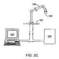
- FIG. 3Cillustrates the housing adapted to cooperate with a mechanical arm.
- the “origin” referred to belowhas to deal with the placement of the position tracking device at the outset of a medical procedure.
- the position tracking deviceWhen the position tracking device is first placed on to a patient, there is a method provided below of establishing the starting position of the device and making sure that position is readily identifiable through out the procedure in case the starting placement of the device is needed.
- the devicethere is a medical device or affecter for transmitting energy into the patient.
- the focal point of the energy transmissionoccurs through a transmissible window.
- the center of the energy transmission area, within the area of the transmissible window,is the “affecter center.”
- the optical sensorsare used to determine the movement and orientation of the device about the affecter center.
- the affecter centeris derived mathematically since an optical sensor cannot be positioned in the exact same location in the housing as the affecter center.
- the medical deviceis an insertion device, then the affecter center is the point on the patient, through which the insertion device is going to penetrate the patient's skin.
- the present inventionrelates to a position tracking device for recording movement of a medical device over a patient.
- the position tracking devicehas a housing adapted to be moved relative to a patient.
- the housinghas a top section and a bottom section.
- the bottom sectionhas a primary transmissible window, and at least one secondary transmissible window.
- An asymmetric flangeis fixedly attached to the bottom section. The flange is positioned substantially near the patient when the housing is moved relative to the patient.
- There is at least one medical devicepositioned within the housing to transmit energy through the primary transmissible window.
- the housinghas a cylindrical form.
- the top sectioncomprises a grip for a user to manipulate the device.
- the bottom sectioncontains a medical device and a means for sensing the movement of the device over a patient.
- the bottom surfaceis preferably smooth and has a low coefficient of friction to facilitate an easy glide over the patient's skin.
- the bottom sectionalso has a plurality of transmissible windows.
- the primary transmissible windowis a portal through which radiant energy of the medical device can affect the patient.
- the transmissible windowis preferably solid, yet transparent to the energy emission of the medical device.
- the primary transmissible windowis preferably made of a smooth material, so as to reduce drag and friction as the device moves over the patient.
- the secondary transmissible windowsallow optical sensors to image the patient's skin.
- optical “mice” technologycan be adapted for medical purposes.
- the optical sensorsimage and record data in the same manner as computer pointing devices. However the signal processing done with the image data is different.
- Image data from the optical sensorsis communicated to a processor operationally associated with the optical sensors.
- the processordetermines the movement and orientation changes from the data provided by the single optical sensor.
- the medical device or affecter centeris offset by some distance ⁇ from the optical sensor.
- the processordetermines movement and orientation changes from the true position of the optical sensor, or calculates movement and orientation changes from an artificial position of the distance ⁇ from the optical sensor to the affecter center.
- two or more optical sensorsare used to generate image data and relay the data to the processor. Using multiple optical sensors it is possible to correlate the image data from all the optical sensors. This allows the determination of movement of the affecter center with much greater accuracy and precision than with a single optical sensor.
- the result of the processor calculationis position data that includes the movement position of the device from one image frame to the next.
- the datamay also include changes in orientation in the event the device is rotated about an axis perpendicular to the plane of the patient and device contact.
- An operatormay move the device during the course of a medical procedure in many different ways, and all movement, whether linear, rotational or angular is determined and recorded.
- the recording of the datamay be done internally such as on a memory device, or relayed to an external device such as a computer, or medical device controller.
- the processorretains sufficient memory of the treatment area extending from the origin that it can identify when the device retraces a path or area that the device has previously passed over. Signals to this effect are relayed to the computer, medical device controller, or to a indicator on the housing itself.
- Positioning the devicerequires the ability to reliably place the device on the same position or origin each time the need arises. For instance, in a therapeutic ultrasound procedure it is desirable to track tissue volumes that have been treated and to distinguish them from tissue that has not been treated. Defining a reference position or origin before a procedure begins allows the device to be repositioned in the same place on the patient at any time.
- the devicehas an asymmetric flange about the bottom section. When the device is placed in contact with the patient, the asymmetric flange rests on the patient's skin. A physician can trace the asymmetric flange using a medical grade ink or a body marker. In the device loses contact with a patient during a medical procedure, the physician can replace the device back on the origin so the outline of the flange is aligned with the flange itself.
- the flangemay be molded into the housing, or made as an attachable accessory.
- the flangemay be replaced by an electronic sensor that allows the position tracking device to be repositioned on the origin (an electronic flange equivalent).
- an electronic flange equivalentan electronic flange equivalent
- a medical deviceis incorporated into the housing.
- the medical devicecan transmit energy through the primary transmissible window.
- the medical devicemay be a therapeutic device, a diagnostic instrument, imaging device or other sensor.
- the primary transmissible windowmust be substantially transparent to the energy produced by the medical device.
- the medical deviceis a laser
- the transmissible windowshould be optically transparent to the frequency of light corresponding to the laser.
- the deviceis an ultrasound device the transmissible window must be acoustically transparent, though it may be opaque to light.
- the medical deviceis a microwave emitter the transmissible window must not interfere with the transmission of microwave energy.
- a radiation seedmay also be used as the medical device, for instance for the treatment of skin cancer.
- the housing of the devicemust contain sufficient shielding to protect the physician and the patient, while the transmissible window is preferably an actuated window so that it can be opened or closed to allow radiation to pass to the patient only when desired.
- the position tracking devicehas a housing having at least one transmissible window, and an aperture through the housing for slidably receiving a medical instrument.
- the housinghas one or more transmissible windows used for the optical sensors as described above.
- the medical deviceis not incorporated into the housing. Instead there is an aperture for slidably receiving a medical instrument, such as a syringe, biopsy needle, catheter insertion tool or the like. The aperture is adapted to receive medical instrument to be inserted into the patient.
- the position tracking devicehas a housing having a primary transmissible window and at least one secondary transmissible window.
- the primary transmissible windowallows an imaging sensor to scan or image the patient's tissue while the optical sensor(s) track the movement and position of the device through the secondary transmissible window(s).
- a medical instrumentmay be inserted into the patient through the aperture.
- the medical imaging sensor combined with the optical sensorsprovide for a greater degree of accuracy in the placement of an insertion device than previously possible in a single device.
- FIG. 1Aillustrates an optical mice of the prior art Having a pair of optical sensors used for tracking changes in orientation.
- the mouseutilizes two optical detectors 555 1 , 555 2 so a user can see on a computer screen the changes in orientation as he or she moves the computer pointing device.
- FIG. 1Billustrates a position tracking device of the present invention and a depth model of tissue as the device is moving over human tissue.
- One or more slides or skids 562are on the lower section 501 of the housing 500 to facilitate gliding of the housing over the skin.
- a medical device 600is enclosed within the housing 500 and has an affecter center 578 artificially defined under the medical device.
- the position tracking devicegenerates a three dimensional map of treatment based on either the mapping of the internal tissue, or the mapping of the affecter radiant energy in the affecter zone 579 , or an overlay of both.
- the housingmay have one or more actuators 582 , 584 , 586 positioned on the top section 564 for easy reach by a user.
- the bottom section 566incorporates an asymmetric flange 592 used to calibrate the positioning of the housing.
- the housingmay incorporate a visual indicators, such as a display panel 242 , a data or communication cable 572 , and/or an on-board processor 570 .
- the housingmay be attached to additional devices as described below.
- FIG. 1Cillustrates a three dimensional map.
- a reliable and highly accurate three dimensional map of patient tissuecan be created.
- the coordination of the precise movement of the position tracking device over the patient combined with detailed ultrasound image datacan be used to create a tissue map.
- a computercan track the precise position of the device over the patient and correlate the ultrasound image data to the position.
- As the housing 500 moves over the patient bodyeach new image from the ultrasound image device is correlated to its respective two dimensional shift on the surface skin.
- Image distortions due to changes in radius of scan, and distortions based on the normal limitations of ultrasound imagingcan be corrected by using an image averaging or image compensation protocol.
- the ultrasound transducerbecomes the medical device 600 in this case.
- the volume of tissue that can be scanned in one pass of the therapy head 500 over the patient body Pis the scan line 579 R.
- FIG. 2Aillustrates a cut away view of the device looking up through the bottom section.
- the housing 500provides the structural basis for the other components.
- Surrounding the medical device 600is a plurality of optical sensors 555 x1-4 . Each optical sensor can image the patient through a plurality of corresponding secondary transmissible windows 554 x1-4 .
- the optical sensorsare linked to an on board processor 570 .
- the processor 570receives data from each optical sensor and averages the data to determine the centered position 610 of the medical device 600 .
- Data generated by the optical sensors 555 x1-4 or the processor 570can be relayed to an external computer 400 through a communication link 572 .
- the communication link 572may be wireless if so desired.
- the processorhas sufficient memory attached to it that it can retain a library of the path the device has traveled during a procedure.
- the devicecan alert a user if the treatment path is about to be retraced by the device. The warning allows a user to prevent retreating the same area.
- the processor 570is in communication with a computer 400 , or a therapy controller 250 , then when the device retraces steps, the processor can alert the computer 400 , or therapy controller 250 so as to prevent the medical device 600 from radiating energy into the same tissue.
- the devicealso has an asymmetric flange 592 about the bottom section 501 to facilitate replacing the device into the reference position.
- the asymmetric flange 592is used to trace out the footprint of the device on to the patient so that the starting location of the device is always known.
- the optical sensorsprovide continuing tracking data to the processor.
- the datais recorded on board in a memory device, or relayed to the external computer for storage and data analysis.
- the position datais can be used by the medical device controller to determine what volumes of tissue have been treated by the medical device affecter and what volumes have not been treated. Should the device pass over an area of the patient that has been previously exposed to radiate energy, the onboard computer may disable the medical instrument so as to not endanger anyone.
- FIG. 2Bprovides a side view of an alternative embodiment.
- the housing 500is shown once again in a cut away view with the optical sensors 555 x1-xn positioned to view the patient through a plurality of secondary transmissible windows 554 x1-xn .
- the top section 564has a grip 568 for a physician to firmly grasp the device and maneuver it as necessary. Once the physician has placed the device in the proper position, the physician may insert a needle or other intrusive device through the aperture 560 .
- the affecter center 578is an artificial point established where the aperture 560 opens to the bottom section 501 . This is the insertion point at which the medical instrument 558 will enter the body of the patient.
- the physicianseeks to insert a device into the patient it is uncertain whether a reference position must be established. If there is no need to establish a reference position or origin, then the flange 592 may be omitted. However if the path taken by the device is of concern to the physician, the device can record the image data from the optical sensors to generate a library of position that have been scanned by the device, and regions that have not been scanned within the treatment area.
- FIG. 2Cshows an embodiment similar to that in FIG. 2B .
- the housing 500Contains a plurality of optical sensors 555 x1-xn .
- There is a first medical device 600is an imaging ultrasound transducer able to produce a scan of a tissue region.
- the affecter center 578is centered in the middle of the imaging transducer.
- An aperture 560extends from the top section 564 through the bottom section 566 and through the first medical device 600 , an imaging transducer in this case.
- the affecter center 578is fixed within the diagnostic ultrasound image field.
- An insertion device 558is passed through the aperture 560 and enters the patient at the affecter center.
- a physiciancan move the device over the surface of the patient while collecting detailed three dimensional tissue data.
- the ultrasound imaging deviceproduces detailed information of the tissue beneath the surface while the optical sensors provide for precise information as to the location of the ultrasound scans.
- the image data and the optical sensor informationcan be combined by relaying the information to a computer 400 through the communication link 572 .
- the informationcan be correlated producing an highly accurate three dimensional map of the patient tissue. This map allows for the precise placement of the insertion device 558 .
- the drawingshows the aperture 560 oriented in a perpendicular alignment with the bottom section 501
- the aperturemay be angled as shown in FIG. 2B .
- the aperturemay be changed within the housing 500 by using a pivot sling, turret device or other means to change the angle of approach of the insertion device 558 to the patient P.
- FIG. 3Aillustrates an alternative embodiment where the housing 500 is more cylindrical in shape.
- the upper chamber 504contains additional electronic and mechanical instruments needed for the proper operation of the first medical device 600 . If the position tracking device is to operate independently without attachment to a computer or other peripheral device, then the top section also contains a power supply (not shown).
- the lower chamber 502contains the first medical device 600 . There is a primary transmissible window 552 being essentially transparent to the radiant energy the first medical device 600 produces.
- the optical sensors 555 x1-xnare arranged around the perimeter of the bottom section 566 of the housing 500 . The position of the optical sensors 555 x1-xn around the perimeter can serve the same function as an asymmetric flange.
- Each optical sensor 555 x1-xnhas a corresponding secondary transmissible window 554 x1-xn . It should be noted that if the primary transmissible window can be made from a material that is also transparent for the optical sensors, then a single transmissible window can be used for the first medical device 600 and the optical sensors 555 x1-xn .
- FIG. 3Billustrates the position tracking device 550 having an attached display 590 .
- the displayallows a physician to visualize the progress of the device from the reference position or origin using a map showing the location of the origin and the current position of the device.
- the devicemay use simple LED indicator lights to provide the user with the appropriate feedback. For instance a small panel of LEDs can provide status indicators of on/off, positive tracking over the tissue or failure to track (indicating a need to reposition the device on the origin) as well as an indicator light to inform the user if the device is traveling over an area of tissue previously treated by the medical device.
- an audible tonecan be used to alert the user to any problems with the device, or to alert the user to those times when the device is retracing paths it previously made.
- the visual representationis preferred as it would likely be the most helpful. The precise nature of the tracking ability allows the map to be relied on for accuracy in a medical procedure, as well as allowing for the repositioning of the device if needed.
- the asymmetric flange 592is shown being at the very bottom of the bottom section.
- the outline or footprint of the flangemay be traced or marked appropriately on the skin.
- the markingscreate the reference position or origin and allow the device to be repositioned on the origin at any time.
- the flangeis preferably asymmetric so the device can be position on the reference point in only one orientation. If the flange were a regular shape, the device could be positioned in the origin in any number of orientations that may not correspond with the proper initial orientation.
- the orientationis critical to ensure the proper treatment of the tissue without over treating some areas and under treating others.
- the position tracking devicecan be used as a stand alone instrument or as part of an ensemble.
- One possible combinationis to use an articulated arm 200 to help support the weight of the device 550 ( FIG. 3C ).
- the articulated arm 200may also include a position tracking system of its own that can be combined with that of the present invention. The combination would allow position information of the patient tissue, and information of movement based on an external coordinate system.
- Such a systemis described in co-pending application Articulating Arm for Medical Procedure U.S. Application Ser. No. 10/751,344.
- the position tracking device 550is operationally connected to a computer 400 and a therapy controller 250 .
- Data from the on board processor 570may be combined with data generated by the articulating arm 200 in the computer 400 .
- the datamay be manipulated according to one or more programs designed to implement, or facilitate the implementation of a medical procedure.
- the computer and any programs used with the computer during the medical proceduresmay help in the construction of a three dimensional map of the patient tissue, as well as real time tracking of the movement of the position tracking device 550 over the patient P.
- the position trackingcan be used in conjunction with the three dimensional map to plot out both surface areas and tissue volumes that remain to be treated during a medical procedure.
- the computer or medical device controllercan act as an interrupt switch, turning the medical device 600 off when the position tracking device passes over tissue that has already been treated.
- Preliminary stepsmay be taken prior to using the position tracking device disclosed.
- the physician and/or patientmust determine the surface area for treatment. Defining the surface involves the selection of a particular area the physician intends to treat according to the medical procedure to be performed. If a non-invasive procedure is to be performed, then the physician must define an area of skin that the device will be used on. If the procedure is to be an invasive one, then the physician or surgeon must ensure that there is sufficient space on the desired tissue for the device to be effectively usable on.
- the surface selectionrequires the surface be relatively smooth and free of irregular features that may cause the position tracking device to lose track of the tissue surface, or be an able to properly determine movement and distance information.
- the position tracking devicemay have varying shapes and sizes allowing it to be specifically adapted for different tissues. Larger housings can be used for non-invasive procedures while smaller housings can be used invasively for sitting on the surface of the kidneys, liver or other organs.
- a secondary initial stepinvolves preparing the surface. After the surface to be treated has been defined, it may be prepared. Preparation for use with the position tracking device requires the surface be relatively clean of particulate matter and smooth. Obviously when dealing with organic tissue an absolutely clean surface is impossible nor desirable, however the surface must be sufficiently clear of loose matter so as to not interfere with the position tracking device and the position tracking. Additional preparation of the tissue may be required to accommodate the medical procedure to be conducted.
- tissue area or volumehas been selected and prepared, a procedure can begin.
- Step 1Placing the position tracking device on the patient. This step involves the proper placement of the device on the selected tissue area or volume to be treated. If the procedure is therapeutic, then it is beneficial to place the device on one part of the area and move the device to the opposite side of the area so as to minimize the potential for over exposing the tissue to the medical device. If the medical device is to be inserted, then it is preferable to offset the position tracking device so that it does not cover the area where the medical instrument is to be inserted. In this manner the position tracking instrument can be moved into position and provide for an origin position separate from the site of device insertion.
- Step 2Defining a reference position or origin. Once the position tracking device is set on the patient, it is necessary to establish a reference position to which the position tracking device can be accurately repositioned from.
- the asymmetric flange about the bottom section of the housingis used as a template for the physician or user to mark the patient. Alternatively a separate template that matches the asymmetric flange can be used prior to the placement of the device. Once the outline or reference position is marked, the separate template is removed and the housing can be set on the patient so the asymmetric flange matches the marking made.
- the reference positionneed not be a complete outline of the asymmetric flange. Sufficient marks on the patient skin that provide with a clear indication of the original position of the device are sufficient. Alternatively the reference position may be delineated with a temporary tattoo, body sticker or other means of marking the patient's skin.
- the optical sensorsmay also be sensitive to a particular color or ink type that allows the reference position to be made based on one or more markings for the optical sensors. In this case the user must have a readily identifiable indicator that the optical sensors have been properly positioned on the origin. Any combination or equivalent means may be used to those described herein.
- the reference positiondoes not have to be within the boundaries of the area to be treated.
- the reference positionmay be more conveniently located outside the boundary of the area to be treated, or may coincide with some natural reference on the patient body, such as a birth mark, scar, or even the patient's belly button.
- Step 3Calibrating the position tracking device to the reference position.
- the userIn this step the user must actuate the on board processor or ancillary computer device so that the position tracking device will “zero” itself to the current position. This is necessary so the movement of the device from the origin can be tracked accurately. However the device must know when the origin has been determined.
- Step 4Treating the patient with a medical device enclosed within the position tracking device while tracking and recording all movement data.
- the position tracking deviceis moved over the surface of the patient body while the optical sensors keep track of movement.
- the medical device within the housingnow transmits its own radiant energy into the patient.
- the on board processormay be operationally linked to the medical device through the medical device controller or an external computer system. In this manner the medical device may be switched on or off depending on the position of the device on the patient. Where the on board processor recognizes an area of the patient that has been previously treated, the medical device may turn off, or stop radiating energy. This prevents the area from being over treated.
- the medical device controller or the external computermay perform the function of controlling the activity of the medical device, and coordinating that activity with the position of the housing according to the three dimensional/two dimensional map.
- the data historycan also keep track of the progress of the radiant energy delivered into the patient.
- the medical devicehas a known affecter region that can be projected into the three dimensional map of the patient tissue. As the housing tracks over the patient, the medical device delivers either continuous or discrete bursts of radiant energy. Overlaying the distribution of the radiant energy can be performed by measuring the residence time of the housing over a specific position, and determining the amount of energy transmitted into the patient. The calculation takes advantage of knowing the affecter region of the medical device, the residence time over any particular position, and the three dimensional map of the tissue of interest.
- an imaging sensorsuch as an ultrasound device, is not necessary to create a map of the radiant energy deposited in the patient. So long as the affecter region of the medical instrument is known it can be projected downward from the two dimensional area map of the tissue being treated.
- the physicianneed only reposition the housing on the reference position and begin the procedure again.
- the position tracking devicemust be recalibrated to the origin. However the data history will remain and the position tracking device will be able to effectively guide the physician to the untreated regions within the desired treatment region.
Landscapes
- Life Sciences & Earth Sciences (AREA)
- Health & Medical Sciences (AREA)
- Biomedical Technology (AREA)
- Molecular Biology (AREA)
- Nuclear Medicine, Radiotherapy & Molecular Imaging (AREA)
- Pathology (AREA)
- Radiology & Medical Imaging (AREA)
- Engineering & Computer Science (AREA)
- Physics & Mathematics (AREA)
- Heart & Thoracic Surgery (AREA)
- Medical Informatics (AREA)
- Biophysics (AREA)
- Surgery (AREA)
- Animal Behavior & Ethology (AREA)
- General Health & Medical Sciences (AREA)
- Public Health (AREA)
- Veterinary Medicine (AREA)
- Ultra Sonic Daignosis Equipment (AREA)
- Endoscopes (AREA)
Abstract
Description
Claims (20)
Priority Applications (1)
| Application Number | Priority Date | Filing Date | Title |
|---|---|---|---|
| US11/027,911US7532201B2 (en) | 2003-12-30 | 2004-12-29 | Position tracking device |
Applications Claiming Priority (2)
| Application Number | Priority Date | Filing Date | Title |
|---|---|---|---|
| US53352803P | 2003-12-30 | 2003-12-30 | |
| US11/027,911US7532201B2 (en) | 2003-12-30 | 2004-12-29 | Position tracking device |
Publications (2)
| Publication Number | Publication Date |
|---|---|
| US20050187463A1 US20050187463A1 (en) | 2005-08-25 |
| US7532201B2true US7532201B2 (en) | 2009-05-12 |
Family
ID=34748913
Family Applications (1)
| Application Number | Title | Priority Date | Filing Date |
|---|---|---|---|
| US11/027,911Expired - Fee RelatedUS7532201B2 (en) | 2003-12-30 | 2004-12-29 | Position tracking device |
Country Status (2)
| Country | Link |
|---|---|
| US (1) | US7532201B2 (en) |
| WO (1) | WO2005065407A2 (en) |
Cited By (63)
| Publication number | Priority date | Publication date | Assignee | Title |
|---|---|---|---|---|
| WO2010036732A1 (en) | 2008-09-25 | 2010-04-01 | Zeltiq Aesthetics, Inc. | Treatment planning systems and methods for body contouring applications |
| US20100217161A1 (en)* | 2009-02-25 | 2010-08-26 | Avi Shalgi | Delivery of therapeutic focused energy |
| US20110238051A1 (en)* | 2010-01-25 | 2011-09-29 | Zeltiq Aesthetics, Inc. | Home-use applicators for non-invasively removing heat from subcutaneous lipid-rich cells via phase change coolants, and associated devices, systems and methods |
| WO2012018562A1 (en) | 2010-07-24 | 2012-02-09 | Medicis Technologies Corporation | Apparatus and methods for non-invasive body contouring |
| US20130018268A1 (en)* | 2011-07-12 | 2013-01-17 | Nivasonix, Llc | Scanning Speed Detection for Freehand High Frequency Ultrasound Transducers |
| US9283409B2 (en) | 2004-10-06 | 2016-03-15 | Guided Therapy Systems, Llc | Energy based fat reduction |
| US9283410B2 (en) | 2004-10-06 | 2016-03-15 | Guided Therapy Systems, L.L.C. | System and method for fat and cellulite reduction |
| US9320537B2 (en) | 2004-10-06 | 2016-04-26 | Guided Therapy Systems, Llc | Methods for noninvasive skin tightening |
| US9375345B2 (en) | 2006-09-26 | 2016-06-28 | Zeltiq Aesthetics, Inc. | Cooling device having a plurality of controllable cooling elements to provide a predetermined cooling profile |
| US9408745B2 (en) | 2007-08-21 | 2016-08-09 | Zeltiq Aesthetics, Inc. | Monitoring the cooling of subcutaneous lipid-rich cells, such as the cooling of adipose tissue |
| US9427600B2 (en) | 2004-10-06 | 2016-08-30 | Guided Therapy Systems, L.L.C. | Systems for treating skin laxity |
| US9440096B2 (en) | 2004-10-06 | 2016-09-13 | Guided Therapy Systems, Llc | Method and system for treating stretch marks |
| US9510802B2 (en) | 2012-09-21 | 2016-12-06 | Guided Therapy Systems, Llc | Reflective ultrasound technology for dermatological treatments |
| US9545523B2 (en) | 2013-03-14 | 2017-01-17 | Zeltiq Aesthetics, Inc. | Multi-modality treatment systems, methods and apparatus for altering subcutaneous lipid-rich tissue |
| USD777338S1 (en) | 2014-03-20 | 2017-01-24 | Zeltiq Aesthetics, Inc. | Cryotherapy applicator for cooling tissue |
| US9655770B2 (en) | 2007-07-13 | 2017-05-23 | Zeltiq Aesthetics, Inc. | System for treating lipid-rich regions |
| US9694212B2 (en) | 2004-10-06 | 2017-07-04 | Guided Therapy Systems, Llc | Method and system for ultrasound treatment of skin |
| US9737434B2 (en) | 2008-12-17 | 2017-08-22 | Zeltiq Aestehtics, Inc. | Systems and methods with interrupt/resume capabilities for treating subcutaneous lipid-rich cells |
| US9827449B2 (en) | 2004-10-06 | 2017-11-28 | Guided Therapy Systems, L.L.C. | Systems for treating skin laxity |
| US9844460B2 (en) | 2013-03-14 | 2017-12-19 | Zeltiq Aesthetics, Inc. | Treatment systems with fluid mixing systems and fluid-cooled applicators and methods of using the same |
| US9861520B2 (en) | 2009-04-30 | 2018-01-09 | Zeltiq Aesthetics, Inc. | Device, system and method of removing heat from subcutaneous lipid-rich cells |
| US9861421B2 (en) | 2014-01-31 | 2018-01-09 | Zeltiq Aesthetics, Inc. | Compositions, treatment systems and methods for improved cooling of lipid-rich tissue |
| US9895560B2 (en) | 2004-09-24 | 2018-02-20 | Guided Therapy Systems, Llc | Methods for rejuvenating skin by heating tissue for cosmetic treatment of the face and body |
| US10046181B2 (en) | 2004-10-06 | 2018-08-14 | Guided Therapy Systems, Llc | Energy based hyperhidrosis treatment |
| US10092346B2 (en) | 2010-07-20 | 2018-10-09 | Zeltiq Aesthetics, Inc. | Combined modality treatment systems, methods and apparatus for body contouring applications |
| US10383787B2 (en) | 2007-05-18 | 2019-08-20 | Zeltiq Aesthetics, Inc. | Treatment apparatus for removing heat from subcutaneous lipid-rich cells and massaging tissue |
| US10420960B2 (en) | 2013-03-08 | 2019-09-24 | Ulthera, Inc. | Devices and methods for multi-focus ultrasound therapy |
| US10426429B2 (en) | 2015-10-08 | 2019-10-01 | Decision Sciences Medical Company, LLC | Acoustic orthopedic tracking system and methods |
| US10524956B2 (en) | 2016-01-07 | 2020-01-07 | Zeltiq Aesthetics, Inc. | Temperature-dependent adhesion between applicator and skin during cooling of tissue |
| US10537304B2 (en) | 2008-06-06 | 2020-01-21 | Ulthera, Inc. | Hand wand for ultrasonic cosmetic treatment and imaging |
| US10555831B2 (en) | 2016-05-10 | 2020-02-11 | Zeltiq Aesthetics, Inc. | Hydrogel substances and methods of cryotherapy |
| US10568759B2 (en) | 2014-08-19 | 2020-02-25 | Zeltiq Aesthetics, Inc. | Treatment systems, small volume applicators, and methods for treating submental tissue |
| US10603521B2 (en) | 2014-04-18 | 2020-03-31 | Ulthera, Inc. | Band transducer ultrasound therapy |
| US10675176B1 (en) | 2014-03-19 | 2020-06-09 | Zeltiq Aesthetics, Inc. | Treatment systems, devices, and methods for cooling targeted tissue |
| US10682297B2 (en) | 2016-05-10 | 2020-06-16 | Zeltiq Aesthetics, Inc. | Liposomes, emulsions, and methods for cryotherapy |
| US10743838B2 (en) | 2015-02-25 | 2020-08-18 | Decision Sciences Medical Company, LLC | Acoustic signal transmission couplants and coupling mediums |
| US10765552B2 (en) | 2016-02-18 | 2020-09-08 | Zeltiq Aesthetics, Inc. | Cooling cup applicators with contoured heads and liner assemblies |
| US10864385B2 (en) | 2004-09-24 | 2020-12-15 | Guided Therapy Systems, Llc | Rejuvenating skin by heating tissue for cosmetic treatment of the face and body |
| US10935174B2 (en) | 2014-08-19 | 2021-03-02 | Zeltiq Aesthetics, Inc. | Stress relief couplings for cryotherapy apparatuses |
| US10952891B1 (en) | 2014-05-13 | 2021-03-23 | Zeltiq Aesthetics, Inc. | Treatment systems with adjustable gap applicators and methods for cooling tissue |
| US10993699B2 (en) | 2011-10-28 | 2021-05-04 | Decision Sciences International Corporation | Spread spectrum coded waveforms in ultrasound diagnostics |
| US11076879B2 (en) | 2017-04-26 | 2021-08-03 | Zeltiq Aesthetics, Inc. | Shallow surface cryotherapy applicators and related technology |
| US11096661B2 (en) | 2013-09-13 | 2021-08-24 | Decision Sciences International Corporation | Coherent spread-spectrum coded waveforms in synthetic aperture image formation |
| US11154418B2 (en) | 2015-10-19 | 2021-10-26 | Zeltiq Aesthetics, Inc. | Vascular treatment systems, cooling devices, and methods for cooling vascular structures |
| US11154274B2 (en) | 2019-04-23 | 2021-10-26 | Decision Sciences Medical Company, LLC | Semi-rigid acoustic coupling articles for ultrasound diagnostic and treatment applications |
| US11207548B2 (en) | 2004-10-07 | 2021-12-28 | Guided Therapy Systems, L.L.C. | Ultrasound probe for treating skin laxity |
| US11224895B2 (en) | 2016-01-18 | 2022-01-18 | Ulthera, Inc. | Compact ultrasound device having annular ultrasound array peripherally electrically connected to flexible printed circuit board and method of assembly thereof |
| US11235179B2 (en) | 2004-10-06 | 2022-02-01 | Guided Therapy Systems, Llc | Energy based skin gland treatment |
| US11241218B2 (en) | 2016-08-16 | 2022-02-08 | Ulthera, Inc. | Systems and methods for cosmetic ultrasound treatment of skin |
| US11338156B2 (en) | 2004-10-06 | 2022-05-24 | Guided Therapy Systems, Llc | Noninvasive tissue tightening system |
| US11382790B2 (en) | 2016-05-10 | 2022-07-12 | Zeltiq Aesthetics, Inc. | Skin freezing systems for treating acne and skin conditions |
| US11395760B2 (en) | 2006-09-26 | 2022-07-26 | Zeltiq Aesthetics, Inc. | Tissue treatment methods |
| US11446175B2 (en) | 2018-07-31 | 2022-09-20 | Zeltiq Aesthetics, Inc. | Methods, devices, and systems for improving skin characteristics |
| US11520043B2 (en) | 2020-11-13 | 2022-12-06 | Decision Sciences Medical Company, LLC | Systems and methods for synthetic aperture ultrasound imaging of an object |
| US11724133B2 (en) | 2004-10-07 | 2023-08-15 | Guided Therapy Systems, Llc | Ultrasound probe for treatment of skin |
| US11883688B2 (en) | 2004-10-06 | 2024-01-30 | Guided Therapy Systems, Llc | Energy based fat reduction |
| US11944849B2 (en) | 2018-02-20 | 2024-04-02 | Ulthera, Inc. | Systems and methods for combined cosmetic treatment of cellulite with ultrasound |
| US11986421B2 (en) | 2006-09-26 | 2024-05-21 | Zeltiq Aesthetics, Inc. | Cooling devices with flexible sensors |
| US12017389B2 (en) | 2019-03-06 | 2024-06-25 | Decision Sciences Medical Company, LLC | Methods for manufacturing and distributing semi-rigid acoustic coupling articles and packaging for ultrasound imaging |
| US12070411B2 (en) | 2006-04-28 | 2024-08-27 | Zeltiq Aesthetics, Inc. | Cryoprotectant for use with a treatment device for improved cooling of subcutaneous lipid-rich cells |
| US12076591B2 (en) | 2018-01-26 | 2024-09-03 | Ulthera, Inc. | Systems and methods for simultaneous multi-focus ultrasound therapy in multiple dimensions |
| US12102473B2 (en) | 2008-06-06 | 2024-10-01 | Ulthera, Inc. | Systems for ultrasound treatment |
| US12377293B2 (en) | 2019-07-15 | 2025-08-05 | Ulthera, Inc. | Systems and methods for measuring elasticity with imaging of ultrasound multi-focus shearwaves in multiple dimensions |
Families Citing this family (24)
| Publication number | Priority date | Publication date | Assignee | Title |
|---|---|---|---|---|
| EP1699360A4 (en)* | 2003-12-30 | 2009-05-06 | Liposonix Inc | Component ultrasound transducer |
| US7319386B2 (en) | 2004-08-02 | 2008-01-15 | Hill-Rom Services, Inc. | Configurable system for alerting caregivers |
| US8117701B2 (en) | 2005-07-08 | 2012-02-21 | Hill-Rom Services, Inc. | Control unit for patient support |
| US9084556B2 (en)* | 2006-01-19 | 2015-07-21 | Toshiba Medical Systems Corporation | Apparatus for indicating locus of an ultrasonic probe, ultrasonic diagnostic apparatus |
| US7828734B2 (en)* | 2006-03-09 | 2010-11-09 | Slender Medical Ltd. | Device for ultrasound monitored tissue treatment |
| US20090048514A1 (en)* | 2006-03-09 | 2009-02-19 | Slender Medical Ltd. | Device for ultrasound monitored tissue treatment |
| US9107798B2 (en)* | 2006-03-09 | 2015-08-18 | Slender Medical Ltd. | Method and system for lipolysis and body contouring |
| US20080208236A1 (en)* | 2007-02-28 | 2008-08-28 | Angiodynamics, Inc. | Dermal marking for use with a medical device |
| TWM322031U (en)* | 2007-06-15 | 2007-11-11 | Unity Opto Technology Co Ltd | Optical control module |
| EP2204040B1 (en)* | 2007-08-28 | 2016-11-09 | Marvell World Trade Ltd. | Determining position and velocity of a handheld device |
| JP5179812B2 (en)* | 2007-09-07 | 2013-04-10 | 株式会社東芝 | Ultrasonic diagnostic apparatus, ultrasonic image processing apparatus, and ultrasonic image processing program |
| US20100274161A1 (en)* | 2007-10-15 | 2010-10-28 | Slender Medical, Ltd. | Implosion techniques for ultrasound |
| US20090240146A1 (en)* | 2007-10-26 | 2009-09-24 | Liposonix, Inc. | Mechanical arm |
| US20110178541A1 (en)* | 2008-09-12 | 2011-07-21 | Slender Medical, Ltd. | Virtual ultrasonic scissors |
| US8593284B2 (en) | 2008-09-19 | 2013-11-26 | Hill-Rom Services, Inc. | System and method for reporting status of a bed |
| US8374313B2 (en)* | 2010-06-11 | 2013-02-12 | Xoft, Inc. | Apparatus and methods for radiation treatment of tissue surfaces |
| WO2013071246A1 (en) | 2011-11-11 | 2013-05-16 | Hill-Rom Services, Inc. | Person support apparatus |
| US9655798B2 (en) | 2013-03-14 | 2017-05-23 | Hill-Rom Services, Inc. | Multi-alert lights for hospital bed |
| CN104027191B (en)* | 2014-07-02 | 2016-02-03 | 河北工业大学 | A kind of road conditions recognition system of above-knee prosthesis |
| US20160317122A1 (en)* | 2015-04-28 | 2016-11-03 | Qualcomm Incorporated | In-device fusion of optical and inertial positional tracking of ultrasound probes |
| GB2561537B (en) | 2017-02-27 | 2022-10-12 | Emteq Ltd | Optical expression detection |
| US20190209077A1 (en)* | 2018-01-05 | 2019-07-11 | L'oreal | Grooming instrument configured to monitor hair loss/growth |
| US20190209078A1 (en)* | 2018-01-05 | 2019-07-11 | L'oreal | Grooming instrument configured to monitor hair loss/growth with varied bristle spacing |
| ES2850083A1 (en)* | 2020-02-21 | 2021-08-25 | Consejo Superior Investigacion | DEVICE TO APPLY FOCUSED PHYSIOTHERAPEUTIC ULTRASOUNDS AND POSITIONING METHOD OF THE SAME (Machine-translation by Google Translate, not legally binding) |
Citations (6)
| Publication number | Priority date | Publication date | Assignee | Title |
|---|---|---|---|---|
| US4137777A (en) | 1977-07-11 | 1979-02-06 | Mediscan Inc. | Ultrasonic body scanner and method |
| US5404387A (en) | 1992-11-13 | 1995-04-04 | Hammond; David J. | Body scanning system |
| US5810008A (en)* | 1996-12-03 | 1998-09-22 | Isg Technologies Inc. | Apparatus and method for visualizing ultrasonic images |
| US6554771B1 (en)* | 2001-12-18 | 2003-04-29 | Koninklijke Philips Electronics N.V. | Position sensor in ultrasound transducer probe |
| US6618038B1 (en) | 2000-06-02 | 2003-09-09 | Hewlett-Packard Development Company, Lp. | Pointing device having rotational sensing mechanisms |
| US7244234B2 (en)* | 2003-11-11 | 2007-07-17 | Soma Development Llc | Ultrasound guided probe device and method of using same |
Family Cites Families (2)
| Publication number | Priority date | Publication date | Assignee | Title |
|---|---|---|---|---|
| US5394875A (en)* | 1993-10-21 | 1995-03-07 | Lewis; Judith T. | Automatic ultrasonic localization of targets implanted in a portion of the anatomy |
| CA2333224A1 (en)* | 2001-01-31 | 2002-07-31 | University Technologies International Inc. | Non-invasive diagnostic method and apparatus for musculoskeletal systems |
- 2004
- 2004-12-29USUS11/027,911patent/US7532201B2/ennot_activeExpired - Fee Related
- 2004-12-29WOPCT/US2004/044044patent/WO2005065407A2/enactiveApplication Filing
Patent Citations (6)
| Publication number | Priority date | Publication date | Assignee | Title |
|---|---|---|---|---|
| US4137777A (en) | 1977-07-11 | 1979-02-06 | Mediscan Inc. | Ultrasonic body scanner and method |
| US5404387A (en) | 1992-11-13 | 1995-04-04 | Hammond; David J. | Body scanning system |
| US5810008A (en)* | 1996-12-03 | 1998-09-22 | Isg Technologies Inc. | Apparatus and method for visualizing ultrasonic images |
| US6618038B1 (en) | 2000-06-02 | 2003-09-09 | Hewlett-Packard Development Company, Lp. | Pointing device having rotational sensing mechanisms |
| US6554771B1 (en)* | 2001-12-18 | 2003-04-29 | Koninklijke Philips Electronics N.V. | Position sensor in ultrasound transducer probe |
| US7244234B2 (en)* | 2003-11-11 | 2007-07-17 | Soma Development Llc | Ultrasound guided probe device and method of using same |
Cited By (132)
| Publication number | Priority date | Publication date | Assignee | Title |
|---|---|---|---|---|
| US11590370B2 (en) | 2004-09-24 | 2023-02-28 | Guided Therapy Systems, Llc | Rejuvenating skin by heating tissue for cosmetic treatment of the face and body |
| US10864385B2 (en) | 2004-09-24 | 2020-12-15 | Guided Therapy Systems, Llc | Rejuvenating skin by heating tissue for cosmetic treatment of the face and body |
| US10328289B2 (en) | 2004-09-24 | 2019-06-25 | Guided Therapy Systems, Llc | Rejuvenating skin by heating tissue for cosmetic treatment of the face and body |
| US9895560B2 (en) | 2004-09-24 | 2018-02-20 | Guided Therapy Systems, Llc | Methods for rejuvenating skin by heating tissue for cosmetic treatment of the face and body |
| US11167155B2 (en) | 2004-10-06 | 2021-11-09 | Guided Therapy Systems, Llc | Ultrasound probe for treatment of skin |
| US10046182B2 (en) | 2004-10-06 | 2018-08-14 | Guided Therapy Systems, Llc | Methods for face and neck lifts |
| US9283410B2 (en) | 2004-10-06 | 2016-03-15 | Guided Therapy Systems, L.L.C. | System and method for fat and cellulite reduction |
| US11883688B2 (en) | 2004-10-06 | 2024-01-30 | Guided Therapy Systems, Llc | Energy based fat reduction |
| US9320537B2 (en) | 2004-10-06 | 2016-04-26 | Guided Therapy Systems, Llc | Methods for noninvasive skin tightening |
| US10610706B2 (en) | 2004-10-06 | 2020-04-07 | Guided Therapy Systems, Llc | Ultrasound probe for treatment of skin |
| US10610705B2 (en) | 2004-10-06 | 2020-04-07 | Guided Therapy Systems, L.L.C. | Ultrasound probe for treating skin laxity |
| US9427600B2 (en) | 2004-10-06 | 2016-08-30 | Guided Therapy Systems, L.L.C. | Systems for treating skin laxity |
| US9440096B2 (en) | 2004-10-06 | 2016-09-13 | Guided Therapy Systems, Llc | Method and system for treating stretch marks |
| US11235179B2 (en) | 2004-10-06 | 2022-02-01 | Guided Therapy Systems, Llc | Energy based skin gland treatment |
| US9522290B2 (en) | 2004-10-06 | 2016-12-20 | Guided Therapy Systems, Llc | System and method for fat and cellulite reduction |
| US9533175B2 (en) | 2004-10-06 | 2017-01-03 | Guided Therapy Systems, Llc | Energy based fat reduction |
| US11235180B2 (en) | 2004-10-06 | 2022-02-01 | Guided Therapy Systems, Llc | System and method for noninvasive skin tightening |
| US11400319B2 (en) | 2004-10-06 | 2022-08-02 | Guided Therapy Systems, Llc | Methods for lifting skin tissue |
| US10603519B2 (en) | 2004-10-06 | 2020-03-31 | Guided Therapy Systems, Llc | Energy based fat reduction |
| US9694211B2 (en) | 2004-10-06 | 2017-07-04 | Guided Therapy Systems, L.L.C. | Systems for treating skin laxity |
| US9694212B2 (en) | 2004-10-06 | 2017-07-04 | Guided Therapy Systems, Llc | Method and system for ultrasound treatment of skin |
| US9707412B2 (en) | 2004-10-06 | 2017-07-18 | Guided Therapy Systems, Llc | System and method for fat and cellulite reduction |
| US9713731B2 (en) | 2004-10-06 | 2017-07-25 | Guided Therapy Systems, Llc | Energy based fat reduction |
| US10603523B2 (en) | 2004-10-06 | 2020-03-31 | Guided Therapy Systems, Llc | Ultrasound probe for tissue treatment |
| US11207547B2 (en) | 2004-10-06 | 2021-12-28 | Guided Therapy Systems, Llc | Probe for ultrasound tissue treatment |
| US9827450B2 (en) | 2004-10-06 | 2017-11-28 | Guided Therapy Systems, L.L.C. | System and method for fat and cellulite reduction |
| US9827449B2 (en) | 2004-10-06 | 2017-11-28 | Guided Therapy Systems, L.L.C. | Systems for treating skin laxity |
| US9833639B2 (en) | 2004-10-06 | 2017-12-05 | Guided Therapy Systems, L.L.C. | Energy based fat reduction |
| US9833640B2 (en) | 2004-10-06 | 2017-12-05 | Guided Therapy Systems, L.L.C. | Method and system for ultrasound treatment of skin |
| US10888717B2 (en) | 2004-10-06 | 2021-01-12 | Guided Therapy Systems, Llc | Probe for ultrasound tissue treatment |
| US11179580B2 (en) | 2004-10-06 | 2021-11-23 | Guided Therapy Systems, Llc | Energy based fat reduction |
| US10888716B2 (en) | 2004-10-06 | 2021-01-12 | Guided Therapy Systems, Llc | Energy based fat reduction |
| US10532230B2 (en) | 2004-10-06 | 2020-01-14 | Guided Therapy Systems, Llc | Methods for face and neck lifts |
| US10010724B2 (en) | 2004-10-06 | 2018-07-03 | Guided Therapy Systems, L.L.C. | Ultrasound probe for treating skin laxity |
| US9283409B2 (en) | 2004-10-06 | 2016-03-15 | Guided Therapy Systems, Llc | Energy based fat reduction |
| US9974982B2 (en) | 2004-10-06 | 2018-05-22 | Guided Therapy Systems, Llc | System and method for noninvasive skin tightening |
| US11338156B2 (en) | 2004-10-06 | 2022-05-24 | Guided Therapy Systems, Llc | Noninvasive tissue tightening system |
| US10010725B2 (en) | 2004-10-06 | 2018-07-03 | Guided Therapy Systems, Llc | Ultrasound probe for fat and cellulite reduction |
| US10010721B2 (en) | 2004-10-06 | 2018-07-03 | Guided Therapy Systems, L.L.C. | Energy based fat reduction |
| US10010726B2 (en) | 2004-10-06 | 2018-07-03 | Guided Therapy Systems, Llc | Ultrasound probe for treatment of skin |
| US10046181B2 (en) | 2004-10-06 | 2018-08-14 | Guided Therapy Systems, Llc | Energy based hyperhidrosis treatment |
| US11697033B2 (en) | 2004-10-06 | 2023-07-11 | Guided Therapy Systems, Llc | Methods for lifting skin tissue |
| US11717707B2 (en) | 2004-10-06 | 2023-08-08 | Guided Therapy Systems, Llc | System and method for noninvasive skin tightening |
| US10238894B2 (en) | 2004-10-06 | 2019-03-26 | Guided Therapy Systems, L.L.C. | Energy based fat reduction |
| US10245450B2 (en) | 2004-10-06 | 2019-04-02 | Guided Therapy Systems, Llc | Ultrasound probe for fat and cellulite reduction |
| US10252086B2 (en) | 2004-10-06 | 2019-04-09 | Guided Therapy Systems, Llc | Ultrasound probe for treatment of skin |
| US10265550B2 (en) | 2004-10-06 | 2019-04-23 | Guided Therapy Systems, L.L.C. | Ultrasound probe for treating skin laxity |
| US10525288B2 (en) | 2004-10-06 | 2020-01-07 | Guided Therapy Systems, Llc | System and method for noninvasive skin tightening |
| US10888718B2 (en) | 2004-10-06 | 2021-01-12 | Guided Therapy Systems, L.L.C. | Ultrasound probe for treating skin laxity |
| US10960236B2 (en) | 2004-10-06 | 2021-03-30 | Guided Therapy Systems, Llc | System and method for noninvasive skin tightening |
| US11207548B2 (en) | 2004-10-07 | 2021-12-28 | Guided Therapy Systems, L.L.C. | Ultrasound probe for treating skin laxity |
| US11724133B2 (en) | 2004-10-07 | 2023-08-15 | Guided Therapy Systems, Llc | Ultrasound probe for treatment of skin |
| US12070411B2 (en) | 2006-04-28 | 2024-08-27 | Zeltiq Aesthetics, Inc. | Cryoprotectant for use with a treatment device for improved cooling of subcutaneous lipid-rich cells |
| US10292859B2 (en) | 2006-09-26 | 2019-05-21 | Zeltiq Aesthetics, Inc. | Cooling device having a plurality of controllable cooling elements to provide a predetermined cooling profile |
| US11179269B2 (en) | 2006-09-26 | 2021-11-23 | Zeltiq Aesthetics, Inc. | Cooling device having a plurality of controllable cooling elements to provide a predetermined cooling profile |
| US11986421B2 (en) | 2006-09-26 | 2024-05-21 | Zeltiq Aesthetics, Inc. | Cooling devices with flexible sensors |
| US11395760B2 (en) | 2006-09-26 | 2022-07-26 | Zeltiq Aesthetics, Inc. | Tissue treatment methods |
| US11219549B2 (en) | 2006-09-26 | 2022-01-11 | Zeltiq Aesthetics, Inc. | Cooling device having a plurality of controllable cooling elements to provide a predetermined cooling profile |
| US9375345B2 (en) | 2006-09-26 | 2016-06-28 | Zeltiq Aesthetics, Inc. | Cooling device having a plurality of controllable cooling elements to provide a predetermined cooling profile |
| US10383787B2 (en) | 2007-05-18 | 2019-08-20 | Zeltiq Aesthetics, Inc. | Treatment apparatus for removing heat from subcutaneous lipid-rich cells and massaging tissue |
| US11291606B2 (en) | 2007-05-18 | 2022-04-05 | Zeltiq Aesthetics, Inc. | Treatment apparatus for removing heat from subcutaneous lipid-rich cells and massaging tissue |
| US9655770B2 (en) | 2007-07-13 | 2017-05-23 | Zeltiq Aesthetics, Inc. | System for treating lipid-rich regions |
| US10675178B2 (en) | 2007-08-21 | 2020-06-09 | Zeltiq Aesthetics, Inc. | Monitoring the cooling of subcutaneous lipid-rich cells, such as the cooling of adipose tissue |
| US9408745B2 (en) | 2007-08-21 | 2016-08-09 | Zeltiq Aesthetics, Inc. | Monitoring the cooling of subcutaneous lipid-rich cells, such as the cooling of adipose tissue |
| US11583438B1 (en) | 2007-08-21 | 2023-02-21 | Zeltiq Aesthetics, Inc. | Monitoring the cooling of subcutaneous lipid-rich cells, such as the cooling of adipose tissue |
| US11723622B2 (en) | 2008-06-06 | 2023-08-15 | Ulthera, Inc. | Systems for ultrasound treatment |
| US10537304B2 (en) | 2008-06-06 | 2020-01-21 | Ulthera, Inc. | Hand wand for ultrasonic cosmetic treatment and imaging |
| US11123039B2 (en) | 2008-06-06 | 2021-09-21 | Ulthera, Inc. | System and method for ultrasound treatment |
| US12102473B2 (en) | 2008-06-06 | 2024-10-01 | Ulthera, Inc. | Systems for ultrasound treatment |
| WO2010036732A1 (en) | 2008-09-25 | 2010-04-01 | Zeltiq Aesthetics, Inc. | Treatment planning systems and methods for body contouring applications |
| US9737434B2 (en) | 2008-12-17 | 2017-08-22 | Zeltiq Aestehtics, Inc. | Systems and methods with interrupt/resume capabilities for treating subcutaneous lipid-rich cells |
| US20100217161A1 (en)* | 2009-02-25 | 2010-08-26 | Avi Shalgi | Delivery of therapeutic focused energy |
| US9861520B2 (en) | 2009-04-30 | 2018-01-09 | Zeltiq Aesthetics, Inc. | Device, system and method of removing heat from subcutaneous lipid-rich cells |
| US11452634B2 (en) | 2009-04-30 | 2022-09-27 | Zeltiq Aesthetics, Inc. | Device, system and method of removing heat from subcutaneous lipid-rich cells |
| US11224536B2 (en) | 2009-04-30 | 2022-01-18 | Zeltiq Aesthetics, Inc. | Device, system and method of removing heat from subcutaneous lipid-rich cells |
| US9314368B2 (en) | 2010-01-25 | 2016-04-19 | Zeltiq Aesthetics, Inc. | Home-use applicators for non-invasively removing heat from subcutaneous lipid-rich cells via phase change coolants, and associates devices, systems and methods |
| US9844461B2 (en) | 2010-01-25 | 2017-12-19 | Zeltiq Aesthetics, Inc. | Home-use applicators for non-invasively removing heat from subcutaneous lipid-rich cells via phase change coolants |
| US20110238051A1 (en)* | 2010-01-25 | 2011-09-29 | Zeltiq Aesthetics, Inc. | Home-use applicators for non-invasively removing heat from subcutaneous lipid-rich cells via phase change coolants, and associated devices, systems and methods |
| US10092346B2 (en) | 2010-07-20 | 2018-10-09 | Zeltiq Aesthetics, Inc. | Combined modality treatment systems, methods and apparatus for body contouring applications |
| WO2012018562A1 (en) | 2010-07-24 | 2012-02-09 | Medicis Technologies Corporation | Apparatus and methods for non-invasive body contouring |
| US20130018268A1 (en)* | 2011-07-12 | 2013-01-17 | Nivasonix, Llc | Scanning Speed Detection for Freehand High Frequency Ultrasound Transducers |
| US10993699B2 (en) | 2011-10-28 | 2021-05-04 | Decision Sciences International Corporation | Spread spectrum coded waveforms in ultrasound diagnostics |
| US11957516B2 (en) | 2011-10-28 | 2024-04-16 | Decision Sciences International Corporation | Spread spectrum coded waveforms in ultrasound diagnostics |
| US11596388B2 (en) | 2011-10-28 | 2023-03-07 | Decision Sciences International Corporation | Spread spectrum coded waveforms in ultrasound diagnostics |
| US9510802B2 (en) | 2012-09-21 | 2016-12-06 | Guided Therapy Systems, Llc | Reflective ultrasound technology for dermatological treatments |
| US9802063B2 (en) | 2012-09-21 | 2017-10-31 | Guided Therapy Systems, Llc | Reflective ultrasound technology for dermatological treatments |
| US10420960B2 (en) | 2013-03-08 | 2019-09-24 | Ulthera, Inc. | Devices and methods for multi-focus ultrasound therapy |
| US11969609B2 (en) | 2013-03-08 | 2024-04-30 | Ulthera, Inc. | Devices and methods for multi-focus ultrasound therapy |
| US11517772B2 (en) | 2013-03-08 | 2022-12-06 | Ulthera, Inc. | Devices and methods for multi-focus ultrasound therapy |
| US9545523B2 (en) | 2013-03-14 | 2017-01-17 | Zeltiq Aesthetics, Inc. | Multi-modality treatment systems, methods and apparatus for altering subcutaneous lipid-rich tissue |
| US9844460B2 (en) | 2013-03-14 | 2017-12-19 | Zeltiq Aesthetics, Inc. | Treatment systems with fluid mixing systems and fluid-cooled applicators and methods of using the same |
| US11607192B2 (en) | 2013-09-13 | 2023-03-21 | Decision Sciences International Corporation | Coherent spread-spectrum coded waveforms in synthetic aperture image formation |
| US11096661B2 (en) | 2013-09-13 | 2021-08-24 | Decision Sciences International Corporation | Coherent spread-spectrum coded waveforms in synthetic aperture image formation |
| US12121394B2 (en) | 2013-09-13 | 2024-10-22 | Decision Sciences International Corporation | Coherent spread-spectrum coded waveforms in synthetic aperture image formation |
| US9861421B2 (en) | 2014-01-31 | 2018-01-09 | Zeltiq Aesthetics, Inc. | Compositions, treatment systems and methods for improved cooling of lipid-rich tissue |
| US10201380B2 (en) | 2014-01-31 | 2019-02-12 | Zeltiq Aesthetics, Inc. | Treatment systems, methods, and apparatuses for improving the appearance of skin and providing other treatments |
| US10912599B2 (en) | 2014-01-31 | 2021-02-09 | Zeltiq Aesthetics, Inc. | Compositions, treatment systems and methods for improved cooling of lipid-rich tissue |
| US10575890B2 (en) | 2014-01-31 | 2020-03-03 | Zeltiq Aesthetics, Inc. | Treatment systems and methods for affecting glands and other targeted structures |
| US10806500B2 (en) | 2014-01-31 | 2020-10-20 | Zeltiq Aesthetics, Inc. | Treatment systems, methods, and apparatuses for improving the appearance of skin and providing other treatments |
| US11819257B2 (en) | 2014-01-31 | 2023-11-21 | Zeltiq Aesthetics, Inc. | Compositions, treatment systems and methods for improved cooling of lipid-rich tissue |
| US10675176B1 (en) | 2014-03-19 | 2020-06-09 | Zeltiq Aesthetics, Inc. | Treatment systems, devices, and methods for cooling targeted tissue |
| USD777338S1 (en) | 2014-03-20 | 2017-01-24 | Zeltiq Aesthetics, Inc. | Cryotherapy applicator for cooling tissue |
| US11351401B2 (en) | 2014-04-18 | 2022-06-07 | Ulthera, Inc. | Band transducer ultrasound therapy |
| US10603521B2 (en) | 2014-04-18 | 2020-03-31 | Ulthera, Inc. | Band transducer ultrasound therapy |
| US10952891B1 (en) | 2014-05-13 | 2021-03-23 | Zeltiq Aesthetics, Inc. | Treatment systems with adjustable gap applicators and methods for cooling tissue |
| US10935174B2 (en) | 2014-08-19 | 2021-03-02 | Zeltiq Aesthetics, Inc. | Stress relief couplings for cryotherapy apparatuses |
| US10568759B2 (en) | 2014-08-19 | 2020-02-25 | Zeltiq Aesthetics, Inc. | Treatment systems, small volume applicators, and methods for treating submental tissue |
| US11191521B2 (en) | 2015-02-25 | 2021-12-07 | Decision Sciences Medical Company, LLC | Acoustic signal transmission couplants and coupling mediums |
| US10743838B2 (en) | 2015-02-25 | 2020-08-18 | Decision Sciences Medical Company, LLC | Acoustic signal transmission couplants and coupling mediums |
| US11839512B2 (en) | 2015-02-25 | 2023-12-12 | Decision Sciences Medical Company, LLC | Acoustic signal transmission couplants and coupling mediums |
| US12251259B2 (en) | 2015-10-08 | 2025-03-18 | Decision Sciences Medical Company, LLC | Acoustic orthopedic tracking system and methods |
| US10426429B2 (en) | 2015-10-08 | 2019-10-01 | Decision Sciences Medical Company, LLC | Acoustic orthopedic tracking system and methods |
| US11737726B2 (en) | 2015-10-08 | 2023-08-29 | Decision Sciences Medical Company, LLC | Acoustic orthopedic tracking system and methods |
| US11154418B2 (en) | 2015-10-19 | 2021-10-26 | Zeltiq Aesthetics, Inc. | Vascular treatment systems, cooling devices, and methods for cooling vascular structures |
| US10524956B2 (en) | 2016-01-07 | 2020-01-07 | Zeltiq Aesthetics, Inc. | Temperature-dependent adhesion between applicator and skin during cooling of tissue |
| US11224895B2 (en) | 2016-01-18 | 2022-01-18 | Ulthera, Inc. | Compact ultrasound device having annular ultrasound array peripherally electrically connected to flexible printed circuit board and method of assembly thereof |
| US10765552B2 (en) | 2016-02-18 | 2020-09-08 | Zeltiq Aesthetics, Inc. | Cooling cup applicators with contoured heads and liner assemblies |
| US10555831B2 (en) | 2016-05-10 | 2020-02-11 | Zeltiq Aesthetics, Inc. | Hydrogel substances and methods of cryotherapy |
| US11382790B2 (en) | 2016-05-10 | 2022-07-12 | Zeltiq Aesthetics, Inc. | Skin freezing systems for treating acne and skin conditions |
| US10682297B2 (en) | 2016-05-10 | 2020-06-16 | Zeltiq Aesthetics, Inc. | Liposomes, emulsions, and methods for cryotherapy |
| US11241218B2 (en) | 2016-08-16 | 2022-02-08 | Ulthera, Inc. | Systems and methods for cosmetic ultrasound treatment of skin |
| US11076879B2 (en) | 2017-04-26 | 2021-08-03 | Zeltiq Aesthetics, Inc. | Shallow surface cryotherapy applicators and related technology |
| US12076591B2 (en) | 2018-01-26 | 2024-09-03 | Ulthera, Inc. | Systems and methods for simultaneous multi-focus ultrasound therapy in multiple dimensions |
| US11944849B2 (en) | 2018-02-20 | 2024-04-02 | Ulthera, Inc. | Systems and methods for combined cosmetic treatment of cellulite with ultrasound |
| US12102557B2 (en) | 2018-07-31 | 2024-10-01 | Zeltiq Aesthetics, Inc. | Methods, devices, and systems for improving skin characteristics |
| US11446175B2 (en) | 2018-07-31 | 2022-09-20 | Zeltiq Aesthetics, Inc. | Methods, devices, and systems for improving skin characteristics |
| US12017389B2 (en) | 2019-03-06 | 2024-06-25 | Decision Sciences Medical Company, LLC | Methods for manufacturing and distributing semi-rigid acoustic coupling articles and packaging for ultrasound imaging |
| US20250144853A1 (en)* | 2019-03-06 | 2025-05-08 | Decision Sciences Medical Company, LLC | Methods for manufacturing and distributing semi-rigid acoustic coupling articles and packaging for ultrasound imaging |
| US11154274B2 (en) | 2019-04-23 | 2021-10-26 | Decision Sciences Medical Company, LLC | Semi-rigid acoustic coupling articles for ultrasound diagnostic and treatment applications |
| US12377293B2 (en) | 2019-07-15 | 2025-08-05 | Ulthera, Inc. | Systems and methods for measuring elasticity with imaging of ultrasound multi-focus shearwaves in multiple dimensions |
| US11520043B2 (en) | 2020-11-13 | 2022-12-06 | Decision Sciences Medical Company, LLC | Systems and methods for synthetic aperture ultrasound imaging of an object |
| US12320893B2 (en) | 2020-11-13 | 2025-06-03 | Decision Sciences Medical Company, LLC | Systems and methods for synthetic aperture ultrasound imaging of an object |
Also Published As
| Publication number | Publication date |
|---|---|
| WO2005065407A2 (en) | 2005-07-21 |
| WO2005065407A3 (en) | 2007-07-05 |
| US20050187463A1 (en) | 2005-08-25 |
Similar Documents
| Publication | Publication Date | Title |
|---|---|---|
| US7532201B2 (en) | Position tracking device | |
| US7318805B2 (en) | Apparatus and method for compensating for respiratory and patient motion during treatment | |
| EP3136973B1 (en) | Ultrasound guided hand held robot | |
| US7993289B2 (en) | Systems and methods for the destruction of adipose tissue | |
| US6216029B1 (en) | Free-hand aiming of a needle guide | |
| US6144875A (en) | Apparatus and method for compensating for respiratory and patient motion during treatment | |
| US6041249A (en) | Device for making a guide path for an instrument on a patient | |
| US7833221B2 (en) | System and method for treatment of tissue using the tissue as a fiducial | |
| US20060089624A1 (en) | System and method for planning treatment of tissue | |
| US20060285641A1 (en) | System, tracker, and program product to facilitate and verify proper target alignment for radiation delivery, and related methods | |
| US20130035590A1 (en) | Systems and methods to assist with internal positioning of instruments | |
| JP2005510289A (en) | Tactile feedback and display in CT images guided robotic systems for interventional techniques | |
| KR20150127031A (en) | System for establishing virtual constraint boundaries | |
| JP2008119472A (en) | System and method for distance measurement of buried plant | |
| Cheng et al. | Needle tip tracking based on optical imaging and AI | |
| Yoshida et al. | Novel ureteroscopic navigation system with a magnetic tracking device: a preliminary ex vivo evaluation | |
| KR20250099056A (en) | Ultrasonic device and its method of guiding irradiation | |
| MXPA98000536A (en) | Hand type free apparatus device for an ag guide |
Legal Events
| Date | Code | Title | Description |
|---|---|---|---|
| AS | Assignment | Owner name:LIPOSONIX, INC., WASHINGTON Free format text:ASSIGNMENT OF ASSIGNORS INTEREST;ASSIGNORS:QUISTGAARD, JENS U.;DESILETS, CHARLES S.;ETCHELLS, TIM;AND OTHERS;REEL/FRAME:016639/0403;SIGNING DATES FROM 20050912 TO 20050923 | |
| AS | Assignment | Owner name:MEDICIS TECHNOLOGIES CORPORATION, WASHINGTON Free format text:CHANGE OF NAME;ASSIGNOR:LIPOSONIX, INC.;REEL/FRAME:022597/0363 Effective date:20090407 Owner name:MEDICIS TECHNOLOGIES CORPORATION,WASHINGTON Free format text:CHANGE OF NAME;ASSIGNOR:LIPOSONIX, INC.;REEL/FRAME:022597/0363 Effective date:20090407 | |
| FPAY | Fee payment | Year of fee payment:4 | |
| AS | Assignment | Owner name:SILICON VALLEY BANK, CALIFORNIA Free format text:SECURITY AGREEMENT;ASSIGNOR:LIPOSONIX, INC.;REEL/FRAME:030147/0642 Effective date:20121031 | |
| AS | Assignment | Owner name:SILICON VALLEY BANK, CALIFORNIA Free format text:SECURITY INTEREST - MEZZANINE LOAN;ASSIGNOR:LIPOSONIX, INC.;REEL/FRAME:030249/0268 Effective date:20120829 | |
| AS | Assignment | Owner name:PARALLEL INVESTMENT OPPORTUNITIES PARTNERS II L.P. Free format text:SHORT-FORM PATENT SECURITY AGREEMENT;ASSIGNOR:LIPOSONIX, INC.;REEL/FRAME:031674/0454 Effective date:20131114 Owner name:CAPITAL ROYALTY PARTNERS II L.P., TEXAS Free format text:SHORT-FORM PATENT SECURITY AGREEMENT;ASSIGNOR:LIPOSONIX, INC.;REEL/FRAME:031674/0454 Effective date:20131114 Owner name:CAPITAL ROYALTY PARTNERS II ? PARALLEL FUND ?A? L. Free format text:SHORT-FORM PATENT SECURITY AGREEMENT;ASSIGNOR:LIPOSONIX, INC.;REEL/FRAME:031674/0454 Effective date:20131114 Owner name:CAPITAL ROYALTY PARTNERS II - PARALLEL FUND "A" L. Free format text:SHORT-FORM PATENT SECURITY AGREEMENT;ASSIGNOR:LIPOSONIX, INC.;REEL/FRAME:031674/0454 Effective date:20131114 | |
| AS | Assignment | Owner name:LIPOSONIX, INC., CALIFORNIA Free format text:RELEASE OF SECURITY INTEREST IN PATENTS;ASSIGNOR:SILICON VALLEY BANK;REEL/FRAME:032126/0531 Effective date:20140123 Owner name:LIPOSONIX, INC., CALIFORNIA Free format text:RELEASE OF SECURITY INTEREST IN PATENTS;ASSIGNORS:CAPITAL ROYALTY PARTNERS II L.P.;CAPITAL ROYALTY PARTNERS II - PARALLEL FUND "A" L.P.;PARALLEL INVESTMENT OPPORTUNITIES PARTNERS II L.P.;REEL/FRAME:032126/0370 Effective date:20140123 | |
| REMI | Maintenance fee reminder mailed | ||
| LAPS | Lapse for failure to pay maintenance fees | ||
| STCH | Information on status: patent discontinuation | Free format text:PATENT EXPIRED DUE TO NONPAYMENT OF MAINTENANCE FEES UNDER 37 CFR 1.362 | |
| FP | Expired due to failure to pay maintenance fee | Effective date:20170512 |