US7531122B2 - Polymer welding using ferromagnetic particles - Google Patents
Polymer welding using ferromagnetic particlesDownload PDFInfo
- Publication number
- US7531122B2 US7531122B2US10/403,995US40399503AUS7531122B2US 7531122 B2US7531122 B2US 7531122B2US 40399503 AUS40399503 AUS 40399503AUS 7531122 B2US7531122 B2US 7531122B2
- Authority
- US
- United States
- Prior art keywords
- polymeric
- polymer
- elements
- ferromagnetic particles
- polymeric element
- Prior art date
- Legal status (The legal status is an assumption and is not a legal conclusion. Google has not performed a legal analysis and makes no representation as to the accuracy of the status listed.)
- Expired - Fee Related, expires
Links
Images


Classifications
- B—PERFORMING OPERATIONS; TRANSPORTING
- B29—WORKING OF PLASTICS; WORKING OF SUBSTANCES IN A PLASTIC STATE IN GENERAL
- B29C—SHAPING OR JOINING OF PLASTICS; SHAPING OF MATERIAL IN A PLASTIC STATE, NOT OTHERWISE PROVIDED FOR; AFTER-TREATMENT OF THE SHAPED PRODUCTS, e.g. REPAIRING
- B29C66/00—General aspects of processes or apparatus for joining preformed parts
- B29C66/70—General aspects of processes or apparatus for joining preformed parts characterised by the composition, physical properties or the structure of the material of the parts to be joined; Joining with non-plastics material
- B29C66/73—General aspects of processes or apparatus for joining preformed parts characterised by the composition, physical properties or the structure of the material of the parts to be joined; Joining with non-plastics material characterised by the intensive physical properties of the material of the parts to be joined, by the optical properties of the material of the parts to be joined, by the extensive physical properties of the parts to be joined, by the state of the material of the parts to be joined or by the material of the parts to be joined being a thermoplastic or a thermoset
- B29C66/731—General aspects of processes or apparatus for joining preformed parts characterised by the composition, physical properties or the structure of the material of the parts to be joined; Joining with non-plastics material characterised by the intensive physical properties of the material of the parts to be joined, by the optical properties of the material of the parts to be joined, by the extensive physical properties of the parts to be joined, by the state of the material of the parts to be joined or by the material of the parts to be joined being a thermoplastic or a thermoset characterised by the intensive physical properties of the material of the parts to be joined
- B29C66/7311—Thermal properties
- B29C66/73115—Melting point
- B29C66/73116—Melting point of different melting point, i.e. the melting point of one of the parts to be joined being different from the melting point of the other part
- B—PERFORMING OPERATIONS; TRANSPORTING
- B29—WORKING OF PLASTICS; WORKING OF SUBSTANCES IN A PLASTIC STATE IN GENERAL
- B29C—SHAPING OR JOINING OF PLASTICS; SHAPING OF MATERIAL IN A PLASTIC STATE, NOT OTHERWISE PROVIDED FOR; AFTER-TREATMENT OF THE SHAPED PRODUCTS, e.g. REPAIRING
- B29C65/00—Joining or sealing of preformed parts, e.g. welding of plastics materials; Apparatus therefor
- B29C65/02—Joining or sealing of preformed parts, e.g. welding of plastics materials; Apparatus therefor by heating, with or without pressure
- B29C65/18—Joining or sealing of preformed parts, e.g. welding of plastics materials; Apparatus therefor by heating, with or without pressure using heated tools
- B29C65/24—Joining or sealing of preformed parts, e.g. welding of plastics materials; Apparatus therefor by heating, with or without pressure using heated tools characterised by the means for heating the tool
- B29C65/30—Electrical means
- B29C65/32—Induction
- B—PERFORMING OPERATIONS; TRANSPORTING
- B29—WORKING OF PLASTICS; WORKING OF SUBSTANCES IN A PLASTIC STATE IN GENERAL
- B29C—SHAPING OR JOINING OF PLASTICS; SHAPING OF MATERIAL IN A PLASTIC STATE, NOT OTHERWISE PROVIDED FOR; AFTER-TREATMENT OF THE SHAPED PRODUCTS, e.g. REPAIRING
- B29C65/00—Joining or sealing of preformed parts, e.g. welding of plastics materials; Apparatus therefor
- B29C65/02—Joining or sealing of preformed parts, e.g. welding of plastics materials; Apparatus therefor by heating, with or without pressure
- B29C65/34—Joining or sealing of preformed parts, e.g. welding of plastics materials; Apparatus therefor by heating, with or without pressure using heated elements which remain in the joint, e.g. "verlorenes Schweisselement"
- B29C65/36—Joining or sealing of preformed parts, e.g. welding of plastics materials; Apparatus therefor by heating, with or without pressure using heated elements which remain in the joint, e.g. "verlorenes Schweisselement" heated by induction
- B29C65/3604—Joining or sealing of preformed parts, e.g. welding of plastics materials; Apparatus therefor by heating, with or without pressure using heated elements which remain in the joint, e.g. "verlorenes Schweisselement" heated by induction characterised by the type of elements heated by induction which remain in the joint
- B29C65/3608—Joining or sealing of preformed parts, e.g. welding of plastics materials; Apparatus therefor by heating, with or without pressure using heated elements which remain in the joint, e.g. "verlorenes Schweisselement" heated by induction characterised by the type of elements heated by induction which remain in the joint comprising single particles, e.g. fillers or discontinuous fibre-reinforcements
- B29C65/3612—Joining or sealing of preformed parts, e.g. welding of plastics materials; Apparatus therefor by heating, with or without pressure using heated elements which remain in the joint, e.g. "verlorenes Schweisselement" heated by induction characterised by the type of elements heated by induction which remain in the joint comprising single particles, e.g. fillers or discontinuous fibre-reinforcements comprising fillers
- B—PERFORMING OPERATIONS; TRANSPORTING
- B29—WORKING OF PLASTICS; WORKING OF SUBSTANCES IN A PLASTIC STATE IN GENERAL
- B29C—SHAPING OR JOINING OF PLASTICS; SHAPING OF MATERIAL IN A PLASTIC STATE, NOT OTHERWISE PROVIDED FOR; AFTER-TREATMENT OF THE SHAPED PRODUCTS, e.g. REPAIRING
- B29C65/00—Joining or sealing of preformed parts, e.g. welding of plastics materials; Apparatus therefor
- B29C65/02—Joining or sealing of preformed parts, e.g. welding of plastics materials; Apparatus therefor by heating, with or without pressure
- B29C65/34—Joining or sealing of preformed parts, e.g. welding of plastics materials; Apparatus therefor by heating, with or without pressure using heated elements which remain in the joint, e.g. "verlorenes Schweisselement"
- B29C65/36—Joining or sealing of preformed parts, e.g. welding of plastics materials; Apparatus therefor by heating, with or without pressure using heated elements which remain in the joint, e.g. "verlorenes Schweisselement" heated by induction
- B29C65/3672—Joining or sealing of preformed parts, e.g. welding of plastics materials; Apparatus therefor by heating, with or without pressure using heated elements which remain in the joint, e.g. "verlorenes Schweisselement" heated by induction characterised by the composition of the elements heated by induction which remain in the joint
- B29C65/3676—Joining or sealing of preformed parts, e.g. welding of plastics materials; Apparatus therefor by heating, with or without pressure using heated elements which remain in the joint, e.g. "verlorenes Schweisselement" heated by induction characterised by the composition of the elements heated by induction which remain in the joint being metallic
- B—PERFORMING OPERATIONS; TRANSPORTING
- B29—WORKING OF PLASTICS; WORKING OF SUBSTANCES IN A PLASTIC STATE IN GENERAL
- B29C—SHAPING OR JOINING OF PLASTICS; SHAPING OF MATERIAL IN A PLASTIC STATE, NOT OTHERWISE PROVIDED FOR; AFTER-TREATMENT OF THE SHAPED PRODUCTS, e.g. REPAIRING
- B29C65/00—Joining or sealing of preformed parts, e.g. welding of plastics materials; Apparatus therefor
- B29C65/02—Joining or sealing of preformed parts, e.g. welding of plastics materials; Apparatus therefor by heating, with or without pressure
- B29C65/34—Joining or sealing of preformed parts, e.g. welding of plastics materials; Apparatus therefor by heating, with or without pressure using heated elements which remain in the joint, e.g. "verlorenes Schweisselement"
- B29C65/36—Joining or sealing of preformed parts, e.g. welding of plastics materials; Apparatus therefor by heating, with or without pressure using heated elements which remain in the joint, e.g. "verlorenes Schweisselement" heated by induction
- B29C65/3672—Joining or sealing of preformed parts, e.g. welding of plastics materials; Apparatus therefor by heating, with or without pressure using heated elements which remain in the joint, e.g. "verlorenes Schweisselement" heated by induction characterised by the composition of the elements heated by induction which remain in the joint
- B29C65/3684—Joining or sealing of preformed parts, e.g. welding of plastics materials; Apparatus therefor by heating, with or without pressure using heated elements which remain in the joint, e.g. "verlorenes Schweisselement" heated by induction characterised by the composition of the elements heated by induction which remain in the joint being non-metallic
- B29C65/3696—Joining or sealing of preformed parts, e.g. welding of plastics materials; Apparatus therefor by heating, with or without pressure using heated elements which remain in the joint, e.g. "verlorenes Schweisselement" heated by induction characterised by the composition of the elements heated by induction which remain in the joint being non-metallic with a coating
- B—PERFORMING OPERATIONS; TRANSPORTING
- B29—WORKING OF PLASTICS; WORKING OF SUBSTANCES IN A PLASTIC STATE IN GENERAL
- B29C—SHAPING OR JOINING OF PLASTICS; SHAPING OF MATERIAL IN A PLASTIC STATE, NOT OTHERWISE PROVIDED FOR; AFTER-TREATMENT OF THE SHAPED PRODUCTS, e.g. REPAIRING
- B29C66/00—General aspects of processes or apparatus for joining preformed parts
- B29C66/01—General aspects dealing with the joint area or with the area to be joined
- B29C66/05—Particular design of joint configurations
- B29C66/10—Particular design of joint configurations particular design of the joint cross-sections
- B29C66/11—Joint cross-sections comprising a single joint-segment, i.e. one of the parts to be joined comprising a single joint-segment in the joint cross-section
- B29C66/114—Single butt joints
- B29C66/1142—Single butt to butt joints
- B—PERFORMING OPERATIONS; TRANSPORTING
- B29—WORKING OF PLASTICS; WORKING OF SUBSTANCES IN A PLASTIC STATE IN GENERAL
- B29C—SHAPING OR JOINING OF PLASTICS; SHAPING OF MATERIAL IN A PLASTIC STATE, NOT OTHERWISE PROVIDED FOR; AFTER-TREATMENT OF THE SHAPED PRODUCTS, e.g. REPAIRING
- B29C66/00—General aspects of processes or apparatus for joining preformed parts
- B29C66/50—General aspects of joining tubular articles; General aspects of joining long products, i.e. bars or profiled elements; General aspects of joining single elements to tubular articles, hollow articles or bars; General aspects of joining several hollow-preforms to form hollow or tubular articles
- B29C66/51—Joining tubular articles, profiled elements or bars; Joining single elements to tubular articles, hollow articles or bars; Joining several hollow-preforms to form hollow or tubular articles
- B29C66/52—Joining tubular articles, bars or profiled elements
- B29C66/522—Joining tubular articles
- B29C66/5221—Joining tubular articles for forming coaxial connections, i.e. the tubular articles to be joined forming a zero angle relative to each other
- B—PERFORMING OPERATIONS; TRANSPORTING
- B29—WORKING OF PLASTICS; WORKING OF SUBSTANCES IN A PLASTIC STATE IN GENERAL
- B29C—SHAPING OR JOINING OF PLASTICS; SHAPING OF MATERIAL IN A PLASTIC STATE, NOT OTHERWISE PROVIDED FOR; AFTER-TREATMENT OF THE SHAPED PRODUCTS, e.g. REPAIRING
- B29C66/00—General aspects of processes or apparatus for joining preformed parts
- B29C66/50—General aspects of joining tubular articles; General aspects of joining long products, i.e. bars or profiled elements; General aspects of joining single elements to tubular articles, hollow articles or bars; General aspects of joining several hollow-preforms to form hollow or tubular articles
- B29C66/51—Joining tubular articles, profiled elements or bars; Joining single elements to tubular articles, hollow articles or bars; Joining several hollow-preforms to form hollow or tubular articles
- B29C66/52—Joining tubular articles, bars or profiled elements
- B29C66/522—Joining tubular articles
- B29C66/5227—Joining tubular articles for forming multi-tubular articles by longitudinally joining elementary tubular articles wall-to-wall (e.g. joining the wall of a first tubular article to the wall of a second tubular article) or for forming multilayer tubular articles
- B29C66/52271—Joining tubular articles for forming multi-tubular articles by longitudinally joining elementary tubular articles wall-to-wall (e.g. joining the wall of a first tubular article to the wall of a second tubular article) or for forming multilayer tubular articles one tubular article being placed inside the other
- B29C66/52272—Joining tubular articles for forming multi-tubular articles by longitudinally joining elementary tubular articles wall-to-wall (e.g. joining the wall of a first tubular article to the wall of a second tubular article) or for forming multilayer tubular articles one tubular article being placed inside the other concentrically, e.g. for forming multilayer tubular articles
- B—PERFORMING OPERATIONS; TRANSPORTING
- B29—WORKING OF PLASTICS; WORKING OF SUBSTANCES IN A PLASTIC STATE IN GENERAL
- B29C—SHAPING OR JOINING OF PLASTICS; SHAPING OF MATERIAL IN A PLASTIC STATE, NOT OTHERWISE PROVIDED FOR; AFTER-TREATMENT OF THE SHAPED PRODUCTS, e.g. REPAIRING
- B29C66/00—General aspects of processes or apparatus for joining preformed parts
- B29C66/50—General aspects of joining tubular articles; General aspects of joining long products, i.e. bars or profiled elements; General aspects of joining single elements to tubular articles, hollow articles or bars; General aspects of joining several hollow-preforms to form hollow or tubular articles
- B29C66/63—Internally supporting the article during joining
- B—PERFORMING OPERATIONS; TRANSPORTING
- B29—WORKING OF PLASTICS; WORKING OF SUBSTANCES IN A PLASTIC STATE IN GENERAL
- B29C—SHAPING OR JOINING OF PLASTICS; SHAPING OF MATERIAL IN A PLASTIC STATE, NOT OTHERWISE PROVIDED FOR; AFTER-TREATMENT OF THE SHAPED PRODUCTS, e.g. REPAIRING
- B29C66/00—General aspects of processes or apparatus for joining preformed parts
- B29C66/70—General aspects of processes or apparatus for joining preformed parts characterised by the composition, physical properties or the structure of the material of the parts to be joined; Joining with non-plastics material
- B29C66/71—General aspects of processes or apparatus for joining preformed parts characterised by the composition, physical properties or the structure of the material of the parts to be joined; Joining with non-plastics material characterised by the composition of the plastics material of the parts to be joined
- B29C66/712—General aspects of processes or apparatus for joining preformed parts characterised by the composition, physical properties or the structure of the material of the parts to be joined; Joining with non-plastics material characterised by the composition of the plastics material of the parts to be joined the composition of one of the parts to be joined being different from the composition of the other part
- B—PERFORMING OPERATIONS; TRANSPORTING
- B29—WORKING OF PLASTICS; WORKING OF SUBSTANCES IN A PLASTIC STATE IN GENERAL
- B29C—SHAPING OR JOINING OF PLASTICS; SHAPING OF MATERIAL IN A PLASTIC STATE, NOT OTHERWISE PROVIDED FOR; AFTER-TREATMENT OF THE SHAPED PRODUCTS, e.g. REPAIRING
- B29C66/00—General aspects of processes or apparatus for joining preformed parts
- B29C66/70—General aspects of processes or apparatus for joining preformed parts characterised by the composition, physical properties or the structure of the material of the parts to be joined; Joining with non-plastics material
- B29C66/72—General aspects of processes or apparatus for joining preformed parts characterised by the composition, physical properties or the structure of the material of the parts to be joined; Joining with non-plastics material characterised by the structure of the material of the parts to be joined
- B29C66/723—General aspects of processes or apparatus for joining preformed parts characterised by the composition, physical properties or the structure of the material of the parts to be joined; Joining with non-plastics material characterised by the structure of the material of the parts to be joined being multi-layered
- B—PERFORMING OPERATIONS; TRANSPORTING
- B29—WORKING OF PLASTICS; WORKING OF SUBSTANCES IN A PLASTIC STATE IN GENERAL
- B29C—SHAPING OR JOINING OF PLASTICS; SHAPING OF MATERIAL IN A PLASTIC STATE, NOT OTHERWISE PROVIDED FOR; AFTER-TREATMENT OF THE SHAPED PRODUCTS, e.g. REPAIRING
- B29C66/00—General aspects of processes or apparatus for joining preformed parts
- B29C66/80—General aspects of machine operations or constructions and parts thereof
- B29C66/81—General aspects of the pressing elements, i.e. the elements applying pressure on the parts to be joined in the area to be joined, e.g. the welding jaws or clamps
- B29C66/812—General aspects of the pressing elements, i.e. the elements applying pressure on the parts to be joined in the area to be joined, e.g. the welding jaws or clamps characterised by the composition, by the structure, by the intensive physical properties or by the optical properties of the material constituting the pressing elements, e.g. constituting the welding jaws or clamps
- B29C66/8126—General aspects of the pressing elements, i.e. the elements applying pressure on the parts to be joined in the area to be joined, e.g. the welding jaws or clamps characterised by the composition, by the structure, by the intensive physical properties or by the optical properties of the material constituting the pressing elements, e.g. constituting the welding jaws or clamps characterised by the intensive physical properties or by the optical properties of the material constituting the pressing elements, e.g. constituting the welding jaws or clamps
- B—PERFORMING OPERATIONS; TRANSPORTING
- B29—WORKING OF PLASTICS; WORKING OF SUBSTANCES IN A PLASTIC STATE IN GENERAL
- B29C—SHAPING OR JOINING OF PLASTICS; SHAPING OF MATERIAL IN A PLASTIC STATE, NOT OTHERWISE PROVIDED FOR; AFTER-TREATMENT OF THE SHAPED PRODUCTS, e.g. REPAIRING
- B29C66/00—General aspects of processes or apparatus for joining preformed parts
- B29C66/80—General aspects of machine operations or constructions and parts thereof
- B29C66/81—General aspects of the pressing elements, i.e. the elements applying pressure on the parts to be joined in the area to be joined, e.g. the welding jaws or clamps
- B29C66/814—General aspects of the pressing elements, i.e. the elements applying pressure on the parts to be joined in the area to be joined, e.g. the welding jaws or clamps characterised by the design of the pressing elements, e.g. of the welding jaws or clamps
- B29C66/8141—General aspects of the pressing elements, i.e. the elements applying pressure on the parts to be joined in the area to be joined, e.g. the welding jaws or clamps characterised by the design of the pressing elements, e.g. of the welding jaws or clamps characterised by the surface geometry of the part of the pressing elements, e.g. welding jaws or clamps, coming into contact with the parts to be joined
- B29C66/81411—General aspects of the pressing elements, i.e. the elements applying pressure on the parts to be joined in the area to be joined, e.g. the welding jaws or clamps characterised by the design of the pressing elements, e.g. of the welding jaws or clamps characterised by the surface geometry of the part of the pressing elements, e.g. welding jaws or clamps, coming into contact with the parts to be joined characterised by its cross-section, e.g. transversal or longitudinal, being non-flat
- B29C66/81421—General aspects of the pressing elements, i.e. the elements applying pressure on the parts to be joined in the area to be joined, e.g. the welding jaws or clamps characterised by the design of the pressing elements, e.g. of the welding jaws or clamps characterised by the surface geometry of the part of the pressing elements, e.g. welding jaws or clamps, coming into contact with the parts to be joined characterised by its cross-section, e.g. transversal or longitudinal, being non-flat being convex or concave
- B29C66/81423—General aspects of the pressing elements, i.e. the elements applying pressure on the parts to be joined in the area to be joined, e.g. the welding jaws or clamps characterised by the design of the pressing elements, e.g. of the welding jaws or clamps characterised by the surface geometry of the part of the pressing elements, e.g. welding jaws or clamps, coming into contact with the parts to be joined characterised by its cross-section, e.g. transversal or longitudinal, being non-flat being convex or concave being concave
- B—PERFORMING OPERATIONS; TRANSPORTING
- B29—WORKING OF PLASTICS; WORKING OF SUBSTANCES IN A PLASTIC STATE IN GENERAL
- B29C—SHAPING OR JOINING OF PLASTICS; SHAPING OF MATERIAL IN A PLASTIC STATE, NOT OTHERWISE PROVIDED FOR; AFTER-TREATMENT OF THE SHAPED PRODUCTS, e.g. REPAIRING
- B29C66/00—General aspects of processes or apparatus for joining preformed parts
- B29C66/80—General aspects of machine operations or constructions and parts thereof
- B29C66/83—General aspects of machine operations or constructions and parts thereof characterised by the movement of the joining or pressing tools
- B29C66/832—Reciprocating joining or pressing tools
- B29C66/8324—Joining or pressing tools pivoting around one axis
- B—PERFORMING OPERATIONS; TRANSPORTING
- B29—WORKING OF PLASTICS; WORKING OF SUBSTANCES IN A PLASTIC STATE IN GENERAL
- B29C—SHAPING OR JOINING OF PLASTICS; SHAPING OF MATERIAL IN A PLASTIC STATE, NOT OTHERWISE PROVIDED FOR; AFTER-TREATMENT OF THE SHAPED PRODUCTS, e.g. REPAIRING
- B29C66/00—General aspects of processes or apparatus for joining preformed parts
- B29C66/80—General aspects of machine operations or constructions and parts thereof
- B29C66/84—Specific machine types or machines suitable for specific applications
- B29C66/857—Medical tube welding machines
- B—PERFORMING OPERATIONS; TRANSPORTING
- B29—WORKING OF PLASTICS; WORKING OF SUBSTANCES IN A PLASTIC STATE IN GENERAL
- B29C—SHAPING OR JOINING OF PLASTICS; SHAPING OF MATERIAL IN A PLASTIC STATE, NOT OTHERWISE PROVIDED FOR; AFTER-TREATMENT OF THE SHAPED PRODUCTS, e.g. REPAIRING
- B29C66/00—General aspects of processes or apparatus for joining preformed parts
- B29C66/70—General aspects of processes or apparatus for joining preformed parts characterised by the composition, physical properties or the structure of the material of the parts to be joined; Joining with non-plastics material
- B29C66/71—General aspects of processes or apparatus for joining preformed parts characterised by the composition, physical properties or the structure of the material of the parts to be joined; Joining with non-plastics material characterised by the composition of the plastics material of the parts to be joined
- B—PERFORMING OPERATIONS; TRANSPORTING
- B29—WORKING OF PLASTICS; WORKING OF SUBSTANCES IN A PLASTIC STATE IN GENERAL
- B29C—SHAPING OR JOINING OF PLASTICS; SHAPING OF MATERIAL IN A PLASTIC STATE, NOT OTHERWISE PROVIDED FOR; AFTER-TREATMENT OF THE SHAPED PRODUCTS, e.g. REPAIRING
- B29C66/00—General aspects of processes or apparatus for joining preformed parts
- B29C66/80—General aspects of machine operations or constructions and parts thereof
- B29C66/81—General aspects of the pressing elements, i.e. the elements applying pressure on the parts to be joined in the area to be joined, e.g. the welding jaws or clamps
- B29C66/814—General aspects of the pressing elements, i.e. the elements applying pressure on the parts to be joined in the area to be joined, e.g. the welding jaws or clamps characterised by the design of the pressing elements, e.g. of the welding jaws or clamps
- B29C66/8145—General aspects of the pressing elements, i.e. the elements applying pressure on the parts to be joined in the area to be joined, e.g. the welding jaws or clamps characterised by the design of the pressing elements, e.g. of the welding jaws or clamps characterised by the constructional aspects of the pressing elements, e.g. of the welding jaws or clamps
- B29C66/81471—General aspects of the pressing elements, i.e. the elements applying pressure on the parts to be joined in the area to be joined, e.g. the welding jaws or clamps characterised by the design of the pressing elements, e.g. of the welding jaws or clamps characterised by the constructional aspects of the pressing elements, e.g. of the welding jaws or clamps being a wrap-around tape or band
- B—PERFORMING OPERATIONS; TRANSPORTING
- B29—WORKING OF PLASTICS; WORKING OF SUBSTANCES IN A PLASTIC STATE IN GENERAL
- B29K—INDEXING SCHEME ASSOCIATED WITH SUBCLASSES B29B, B29C OR B29D, RELATING TO MOULDING MATERIALS OR TO MATERIALS FOR MOULDS, REINFORCEMENTS, FILLERS OR PREFORMED PARTS, e.g. INSERTS
- B29K2105/00—Condition, form or state of moulded material or of the material to be shaped
- B29K2105/06—Condition, form or state of moulded material or of the material to be shaped containing reinforcements, fillers or inserts
- B29K2105/16—Fillers
- B29K2105/162—Nanoparticles
- B—PERFORMING OPERATIONS; TRANSPORTING
- B29—WORKING OF PLASTICS; WORKING OF SUBSTANCES IN A PLASTIC STATE IN GENERAL
- B29K—INDEXING SCHEME ASSOCIATED WITH SUBCLASSES B29B, B29C OR B29D, RELATING TO MOULDING MATERIALS OR TO MATERIALS FOR MOULDS, REINFORCEMENTS, FILLERS OR PREFORMED PARTS, e.g. INSERTS
- B29K2995/00—Properties of moulding materials, reinforcements, fillers, preformed parts or moulds
- B29K2995/0003—Properties of moulding materials, reinforcements, fillers, preformed parts or moulds having particular electrical or magnetic properties, e.g. piezoelectric
- B29K2995/0008—Magnetic or paramagnetic
- B—PERFORMING OPERATIONS; TRANSPORTING
- B29—WORKING OF PLASTICS; WORKING OF SUBSTANCES IN A PLASTIC STATE IN GENERAL
- B29L—INDEXING SCHEME ASSOCIATED WITH SUBCLASS B29C, RELATING TO PARTICULAR ARTICLES
- B29L2009/00—Layered products
- B—PERFORMING OPERATIONS; TRANSPORTING
- B29—WORKING OF PLASTICS; WORKING OF SUBSTANCES IN A PLASTIC STATE IN GENERAL
- B29L—INDEXING SCHEME ASSOCIATED WITH SUBCLASS B29C, RELATING TO PARTICULAR ARTICLES
- B29L2023/00—Tubular articles
- B29L2023/005—Hoses, i.e. flexible
- B—PERFORMING OPERATIONS; TRANSPORTING
- B29—WORKING OF PLASTICS; WORKING OF SUBSTANCES IN A PLASTIC STATE IN GENERAL
- B29L—INDEXING SCHEME ASSOCIATED WITH SUBCLASS B29C, RELATING TO PARTICULAR ARTICLES
- B29L2031/00—Other particular articles
- B29L2031/753—Medical equipment; Accessories therefor
- B29L2031/7542—Catheters
- B29L2031/7543—Balloon catheters
Definitions
- the disclosuregenerally relates to bonding techniques and, more particularly, relates to methods and apparatuses for bonding polymeric materials, including those found in catheters.
- Bonding or welding of two or more polymeric componentscan be accomplished according to a variety of methods.
- medical devicessuch as balloon catheters, or the like
- the polymeric componentscan be placed within a heated clam shell, or mold-type of device, which surrounds the polymeric material, and transfers heat from the material of the clam shell to the material of the polymeric component.
- the polymeric materialscan be exposed to a hot air stream which is at a temperature sufficient to melt the polymer.
- a disadvantage of such systemsis the time required to bring the polymer to a molding temperature is so great that the transferred heat tends to dissipate throughout the polymeric material and to any adjoining areas of the device. It is therefore difficult to restrict the area affected by the heat.
- the polymeric materialit is known to expose a form of energy to the welding area to heat the polymeric material either by direct absorption by the polymeric material, or indirectly, by adding an energy-absorbing additive through the polymer.
- an energy-absorbing additiveFor example, with regard to laser welding, it is known to disperse an additive throughout the polymeric material which is adapted to absorb the laser frequency. The polymeric material is heated by the hysterisis losses resulting from the laser frequency absorbing additive. While the polymeric material can be heated quickly according to such a method, and the welding spot can be precisely located by direct placement of the energy-absorbing additive, it is difficult to control the temperature accurately.
- the electromagnetic fieldcan pass through all polymers and therefore heat ferromagnetic material placed on the inside of such structures, therefore enabling heating from the inside out.
- the addition of the ferromagnetic material to the device being createdhas certain inherent drawbacks.
- the particle size of the ferromagnetic materials currently in usewhich are on the order of at least one micron, is such that the particles themselves are often as thick as the walls or individual polymer layers of the devices being created, thereby creating weak spots due to a lack of a chemical connection between the polymer matrix and the ferromagnetic particles.
- the addition of the ferromagnetic materialwill also often stiffen the bond site, a disadvantage when the medical device being created must be flexible.
- a disadvantage of large (i.e., larger than one micron) ferromagnetic particlesis the relatively small surface-to-volume ratio in comparison to smaller nano-sized ferromagnetic particles.
- dissimilar polymeric materialseach containing a micro-dispersion of fine-micron ferromagnetic powders may be bonded to one another using a specially compounded thermoplastic elastomer, containing ferromagnetic material.
- the compound materialcontains material similar to that in the polymeric materials being bonded, and the entire composite is heated to the fusion temperature of the same polymeric materials in order to form a chemical bond.
- the heatis generated using a high alternating current source that results in heat losses between the thermoplastic base material and the abutting joint surface with the heat flowing from the metal filler and melting the adjoining surfaces.
- this technologyis in need of further refinements.
- Such bonding systemshave been used in the consumer appliance, automotive and large medical device markets.
- Catheter assemblyis characterized by tight (narrow) tolerance, small bond gap applications, and one would not expect success using existing bonding techniques. Additionally, it would be advantageous to have a bonding process for catheter assembly and other contexts that would permit binding of polymeric materials that themselves do not necessarily contain ferromagnetic materials.
- catheter bonding technologiesare typically limited to two primary technologies: adhesive bonded catheters and thermally bonded catheters.
- Adhesive-bonded cathetersinclude catheters that require high melt flow polymer adhesives to join incompatible polymeric components together. This technology is undesirable from an operational cost and efficiency perspective due to relatively lengthy cure times, etc.
- Thermally-bonded cathetersinclude catheters that join compatible polymeric components together. This technology is substantially limiting because the polymeric components to be joined must be of substantially similar, if not identical composition.
- a method of bonding multiple polymeric elementsmay comprise the steps of distributing ferromagnetic particles through a molding device, placing multiple polymeric elements into operative association with the molding device, exposing the molding device to an electromagnetic field, and heating any polymeric elements by way of contact with the molding device.
- a method of bonding multiple polymeric elements togethermay comprise the steps of providing a first polymeric element, providing a second polymeric element, applying a material containing ferromagnetic particles to an outside surface of at least one of the first and second polymeric elements, engaging the first and second polymeric elements with the material containing ferromagnetic particles being placed between the first and second polymeric elements, and exposing the material containing ferromagnetic particles to an electromagnetic field. The exposure causes the material to rise in temperature and thereby fuse the first and second polymeric elements together.
- an apparatus for bonding first and second polymeric elements togethermay comprise a molding element with a surface complementary to at least one of the first and second polymeric elements, ferromagnetic particles operatively associated with the molding element, and a magnetic field source to subject the molding element to a magnetic field.
- the molding element surfaceis adapted to engage at least one of the first and second elements.
- a method of bonding multiple polymeric elements togethermay comprise the steps of distributing ferromagnetic particles through a molding device, placing multiple polymeric elements into operative association with the molding device, placing an interface composition into operative association with the multiple polymeric elements, and heating the polymeric elements and interface composition at least to a fusion temperature of the polymeric element with the highest fusion temperature.
- a method of bonding multiple polymeric elements togethermay comprise the steps of providing a first polymeric element comprising a first polymer, providing a second polymeric element comprising a second polymer, applying an interface composition that comprises ferromagnetic particles, the first polymer, and the second polymer, to a surface of at least one of the first and second polymeric elements, engaging the first and second polymeric elements at a polymeric interface with the interface composition being placed between the first and second polymeric elements, and exposing the polymeric elements and interface composition to an electromagnetic field, the exposing step causing said elements and composition to rise in temperature and thereby fuse the first and second polymeric elements together.
- a method of bonding multiple polymeric elements togetheris provided.
- the methodmay comprise the following steps. First a molding device is provided.
- the multiple polymeric elementsare placed into operative association with the molding device such that a polymeric element contacts an adjacent polymeric element at a polymeric interface, and wherein there are ferromagnetic particles present within about 500 nanometers (nm) of a plane parallel to surfaces of two adjacent polymeric elements.
- the said planeis equidistant from said surfaces at the polymeric interface.
- An interface compositionis placed in operative association with the multiple polymeric elements at the polymeric interfaces.
- the polymeric elements and interface compositionare heated at least to a fusion temperature of the polymeric element with the highest fusion temperature.
- a method of bonding multiple polymeric elements togetheris provided.
- the methodmay comprise the following steps.
- a first polymeric elementis provided that comprises a first polymer.
- a second polymeric elementis provided that comprises a second polymer.
- An interface compositionis applied that comprises the first polymer and the second polymer to a surface of at least one of the first and second polymeric elements.
- the first and second polymeric elementsare engaged at an interface with the interface composition being placed between the first and second polymeric elements.
- the polymeric elements and interface compositionare exposed to an electromagnetic field.
- This exposure stepcauses said elements and composition to rise in temperature and thereby fuse the first and second polymeric elements together, wherein there are ferromagnetic particles within 500 nm of a plane parallel to surfaces of two adjacent polymeric elements, said plane being equidistant from said surfaces.
- a method of bonding multiple polymeric elements togethermay comprise the following steps. Ferromagnetic particles are distributed through a molding device. Multiple polymeric elements are placed into operative association with the molding device, wherein the multiple polymeric elements comprise at least a first polymeric element and a second polymeric element.
- the first polymeric elementcomprises a first polymer and a second polymeric element comprises a second polymer.
- the first polymeris present at less than 99.999% by weight in the second polymeric element.
- the second polymeris present at less than 99.999% by weight in the first polymeric element.
- a thermoplastic elastomer (TPE) compositionis placed into operative association with the multiple polymeric elements including placing the interface composition between the first and second polymeric elements.
- the TPE composition of the second placing stepcomprises the first polymer.
- the polymeric elements and TPE compositionare heated at least to a fusion temperature of the polymeric element with the highest fusion temperature.
- a method of bonding multiple catheter componentsmay comprise the following steps. Ferromagnetic particles are distributed through a molding device. Multiple polymeric elements are placed into operative association with the molding device, wherein each polymeric element is operatively associated with a catheter component.
- the multiple polymeric elementscomprise at least a first polymeric element operatively associated with a first catheter component and a second polymeric element operatively associated with a second catheter component.
- the first polymeric elementcomprises a first polymer and a second polymeric element comprises a second polymer.
- the first polymeris present at less than 99.999% by weight in the second polymeric element.
- the second polymeris present at less than 99.999% by weight in the first polymeric element.
- thermoplastic elastomer (TPE) compositionis placed into operative association with the multiple polymeric elements including placing the interface composition between the first and second polymeric elements.
- the thermoplastic elastomer (TPE) composition of the second placing stepcomprises the first polymer, the second polymer and ferromagnetic particles.
- the polymeric elements and thermoplastic elastomer (TPE) compositionare heated at least to a fusion temperature of the polymeric element with the highest fusion temperature.
- a method of bonding multiple catheter componentsmay comprise the following steps.
- a molding deviceis provided. Multiple polymeric elements are placed into operative association with the molding device, wherein each polymeric element is operatively associated with a catheter component.
- the multiple polymeric elementscomprise at least a first polymeric element operatively associated with a first catheter component and a second polymeric element operatively associated with a second catheter component.
- the first polymeric elementcomprises a first polymer and a second polymeric element comprises a second polymer.
- the first polymeris present at less than 99.999% by weight in the second polymeric element.
- the second polymeris present at less than 99.999% by weight in the first polymeric element.
- An interface compositionis placed into operative association with the multiple polymeric elements including placing the interface composition between the first and second polymeric elements; wherein the interface composition of the second placing step comprises the first polymer and the second polymer.
- the polymeric elements and interface compositionare heated at least to a fusion temperature of the polymeric element with the highest fusion temperature.
- a method of bonding multiple polymeric elements togetheris provided.
- the methodmay comprise the following steps.
- a first polymeric element comprising a first polymeris provided.
- a second polymeric element comprising the second polymeris provided.
- the first polymeric elementcomprises less than 99.999% by weight of the second polymer.
- the second polymeric elementcomprises less that 99.999% by weight of the first polymer.
- a thermoplastic elastomer (TPE) compositioncomprising ferromagnetic particles, the first polymer, and the second polymer, is applied to a surface of at least one of the first and second polymeric elements.
- the first and second polymeric elementsare engaged at an interface with the TPE composition being placed between the first and second polymeric elements.
- the polymeric elements and TPE compositionare exposed to an electromagnetic field, the exposing step causing said elements and composition to rise in temperature and thereby fuse the first and second polymeric elements together.
- a method of bonding two catheter components togetheris provided.
- the methodmay comprise the following steps.
- a first polymeric element comprising a first polymeris provided.
- a second polymeric element comprising the second polymeris provided.
- the first polymeric elementcomprises less than 99.999% by weight of the second polymer.
- the second polymeric elementcomprises less that 99.999% by weight of the first polymer.
- the first polymeric elementis operatively associated with a first catheter component and the second polymeric element is operatively associated with a second catheter component.
- a thermoplastic elastomer (TPE) compositioncomprising ferromagnetic particles, the first polymer, and the second polymer, is applied to an outside surface of at least one of the first and second polymeric elements.
- the first and second polymeric elementsare engaged at a polymeric interface with the TPE composition being placed between the first and second polymeric elements.
- the polymeric elements and TPE compositionare exposed to an electromagnetic field, the exposing step causing said elements and composition to rise in temperature and thereby fuse the first and second polymeric elements together.
- a method of bonding multiple polymeric elements togetheris provided.
- the methodmay comprise the following steps.
- a first polymeric element comprising a first polymeris provided.
- a second polymeric element comprising the second polymeris provided.
- the first polymeric elementcomprises less than 99.999% by weight of the second polymer.
- the second polymeric elementcomprises less that 99.999% by weight of the first polymer.
- An interface composition, comprising the first polymer and the second polymeris applied to a surface of at least one of the first and second polymeric elements.
- the first and second polymeric elementsare engaged at an interface with the interface composition being placed between the first and second polymeric elements.
- the polymeric elements and interface compositionare heated at least to a fusion temperature of the polymeric element with the highest fusion temperature.
- the disclosureincludes, as an additional aspect, all embodiments of the disclosure narrower in scope in any way than the variations specifically mentioned above.
- the applicant(s)invented the full scope of the claims appended hereto, the claims appended hereto are not intended to encompass within their scope the prior art work of others. Therefore, in the event that statutory prior art within the scope of a claim is brought to the attention of the applicants by a Patent Office or other entity or individual, the applicant(s) reserve the right to exercise amendment rights under applicable patent laws to redefine the subject matter of such a claim to specifically exclude such statutory prior art or obvious variations of statutory prior art from the scope of such a claim. Variations of the disclosure defined by such amended claims also are intended as aspects of the disclosure.
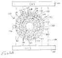
- FIG. 1is the diagrammatic cross-sectional view of the apparatus according to the teachings of the disclosure
- FIG. 2is a diagrammatic cross-sectional view of an alternative embodiment of an apparatus constructed in accordance with the teachings of the disclosure
- FIG. 3is a diagrammatic cross-sectional view of a second alternative embodiment of an apparatus constructed in accordance with the teachings of the disclosure
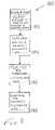
- FIG. 4is a flow chart depicting sample steps which may be taken according to a first method taught by the disclosure
- FIG. 5is a flow chart depicting a sample sequence of steps which may be taken according to a second method taught by the disclosure.
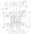
- FIG. 6Ais the diagrammatic cross-sectional view of a third alternative embodiment of an apparatus constructed in accordance with the teachings of the disclosure.
- FIG. 6Bis an enlargement of one segment of the view shown in FIG. 6A , and highlighting additional teachings of the disclosure.
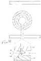
- FIG. 6Cis the diagrammatic cross-sectional view of a variation on the embodiment of that shown in FIG. 6A .
- FIG. 7Ais the diagrammatic cross-sectional view of a fourth alternative embodiment of an apparatus constructed in accordance with the teachings of the disclosure.
- FIG. 7Bis an enlargement of the view shown in FIG. 7A , and highlighting additional teachings of the disclosure.
- FIG. 7Cis the diagrammatic cross-sectional view of a variation on the embodiment of that shown in FIG. 7A .
- FIG. 8is a flow chart depicting sample steps that may be taken according to a third method taught by the disclosure.
- FIG. 9is a flow chart depicting sample steps that may be taken according to a fourth method taught by the disclosure.
- FIG. 10is a flow chart depicting sample steps that may be taken according to a fifth method taught by the disclosure.
- FIG. 11is a flow chart depicting sample steps that may be taken according to a sixth method taught by the disclosure.
- a bonding apparatus constructed in accordance with the teachings of the disclosureis generally referred to by reference numeral 20 .
- the following disclosurewill be provided with specific reference to the bonding of polymeric materials for the creation of medical devices such as balloon catheters, but it is to be understood that the bonding methods and apparatus disclosed herein can be used for the creation of multiple other devices including other medical devices.
- a first polymeric material 22which may be the inner lining of a balloon catheter, is shown being bonded to a second polymeric material 24 , which may be the outer surface of a balloon catheter.
- suitable polymers for such usageinclude polytetrafluoroethylene (PTFE), polytetrafluoroethylene copolymer, tetrafluoro ethylene (TFE), polyvinylidine fluoride (PVDF), polyamides, polyamide/ether block copolymers, polyester/ether block copolymers, polyolefins, polypropylene (PP), polyurethane (PU), ethylene vinyl acetate copolymers (EVA), polyethylene terephthalate (PET), polyethylene napthalenedicarboxylate (PEN), polyethylene (PE), polyamide polymers (PA), Nylon 6, Nylon 6,6, Nylon 6,6/6, Nylon 11 and Nylon 12, as well as many other types of
- a coating of ferromagnetic material 26is provided between the first and second polymers 22 , 24 .
- Many ferromagnetic particlesare suitable for such use, but can be provided in nano-sized particles made of compositions of magnetite in the form of Fe 3 O 4 , Fe 2 O 3 , Cr 2 O 3 and FeCr 2 O 4 .
- the specific composition of the nano-particle made out of alloys of such materialsdefines the Curie temperature.
- the specific ratio of the oxidesis determined by the oxygen flow. For example, in making FexOy nano-particles, one is able to increase the ratio Fe 2 O 3 ⁇ Fe 3 O 4 by increasing the oxygen flow and vice versa.
- Such nano-particleshave been found to be advantageous due to, among other things, their relatively small particle size, which is typically on the order of 5-10 nanometers. Such sizes are advantageous in the formation of relatively small medical devices to avoid the creation of the weak spots referenced above, and also to result in better heat transfer from the embedded particles to the surrounding polymer matrix due to their large surface-to-volume ratio. When embedded inside a polymer matrix, it is advantageous to have a chemical connection between the particles and the matrix.
- a magnetic field 28is created by an anode 30 and a cathode 32 .
- the magnetic field 28can be created by any other suitable form of apparatus.
- the first and second polymeric materials 22 , 24 and the ferromagnetic material 26form an assembly 33 placed within the magnetic field 28 .
- FIGS. 2 and 3are dissimilar to that of FIG. 1 in that the ferromagnetic material 26 is not divided between the polymeric materials 22 , 24 and, thus, does not remain within the created medical device. Rather, as shown first with regard to FIG. 2 , the ferromagnetic material 26 is provided as an outer layer of a molding device 34 .
- the molding device 34can be provided in a number of forms, but as depicted in FIG. 2 , includes a clam shell 36 and a mandrel 38 .
- the clam shell 36may include first and second complementary sections 40 , 42 joined by a hinge 44 .
- the clam shell sections 40 , 42can be pivoted about the hinge 44 to allow for access of the first and second polymeric materials 22 , 24 into and out of the clam shell 36 .
- Each of the clam shell sections 40 , 42include an interior surface 46 upon which is coated a layer of ferromagnetic material 48 .
- the shape of the clam shell sections 40 , 42 as well as the interior surfaces 46are so as to be congruent with the outer shape of the first polymeric material 50 .
- Radially inward and adjacent to the first polymeric material 50is a second polymeric material 52 , which rests against a second layer of ferromagnetic material 54 .
- the second layer of ferromagnetic material 54is coated on an outer surface 56 of the mandrel 38 . Accordingly, it can be seen that the first and second polymeric materials 50 , 52 are supported both from the outside by the clam shell 36 , and from the inside by the mandrel 38 . Moreover, due to the provision of first and second layers of ferromagnetic material 48 , 54 , the heat created thereby, when exposed to a magnetic field 58 , is able to be more quickly dissipated through the first and second layers of polymeric material 50 , 52 . Again, the magnetic field 58 can be created by an anode and a cathode ( 60 , 62 ), or by any other suitable form of magnetic field creation.
- FIG. 3is similar to that of FIG. 2 , but for the provision of magnetic material 64 directly within the clam shell 36 , and the mandrel 38 . Accordingly, wherein like elements are depicted, like reference numerals are employed. Such an embodiment could be provided by casting the clam shell sections 40 , 42 from molten material containing the ferromagnetic material therein, or any other suitable formation technique.
- the ferromagnetic materialcould be provided in the form of a plurality of rings longitudinally spaced along the first and second polymeric layers.
- the ferromagnetic materialcan be placed in only those positions where the bonding is desired.
- a first step 66may be to provide subcomponents such as the first polymeric material 22 and the second polymeric material 24 .
- a second step 68would be to provide the layer of ferromagnetic material 26 .
- the step 68may be accomplished by applying a paint with dissolved ferromagnetic particles.
- a third step 70may be to then assemble the first and second polymeric layers 22 , 24 with the ferromagnetic material 26 therebetween.
- a fourth step 72would be to expose the first and second polymeric materials 22 , 24 and ferromagnetic material 26 to the magnetic field 28 by, for example, energizing the anode and cathode 30 , 32 .
- the magnetic field 28causes vibration of the ferromagnetic material 26 , with the resulting hysterisis losses causing the ferromagnetic material 26 to rise in temperature, and accordingly for the first and second polymeric materials 22 , 24 to rise in temperature as well.
- the polymersare heated to a temperature sufficient to allow for them to fuse together, without overheating the materials.
- a first step 74is to provide the molding device 34 with the ferromagnetic material already therein. As indicated above, this can be accomplished by painting an inner or outer surface of the molding device 34 with the ferromagnetic material, dipping the molding device in the ferromagnetic material, molding or otherwise fabricating the molding components to have the ferromagnetic material already therein, or the like.
- a second step 76may then be to mount the subcomponents to the molding device 34 , or the molding device 34 to the subcomponents. More specifically, the first polymer 50 may be mounted to the mandrel 38 , with the second polymer 52 then being mounted to the outside of the first polymer 50 .
- the first and second polymeric materials 50 , 52 , and the mandrel 38may all be placed inside the clam shell 36 .
- a third and final step 78may then be to subject the assembly to the magnetic field 58 as by energizing the anode and cathode 60 , 62 and heating the components to the Curie temperature of the ferromagnetic material as indicated above.
- a bonding apparatus 110consistent with the teachings of the disclosure is shown that may be placed between an anode 100 and cathode 105 capable of generating a magnetic field 108 along with any other necessary equipment as understood by those of skill in the art.
- a first polymeric element 115may be provided that comprises both an interior 116 and an exterior surface 117 .
- the first polymeric element 115may further comprise a first polymer 118 .
- a second polymeric element 125may be provided that comprises both an includes an interior 126 and an exterior surface 127 .
- the second polymeric element 125may further comprise a second polymer 128 .
- first polymeric element 115 and second polymeric element 125are interconnected between first polymeric element 115 and second polymeric element 125 .
- an interface composition 140operatively associated with the first and second polymeric elements 115 and 125 .
- This disclosuredoes not limit the number of types of polymers that can be in an interface composition. This disclosure also does not limit the number of polymeric elements that may be joined.
- the bonding apparatus 110may comprise a molding device 145 such as a clam shell 150 or a mandrel 160 .
- the clam shell 150may include first and second complementary sections 152 , 154 joined by a hinge 156 . Accordingly, it can be seen that the clam shell sections 152 , 154 can be pivoted about the hinge 156 to allow for access of the first and second polymeric elements 115 and 125 into and out of clam shell 150 .
- Both complementary sections 152 , 154include an interior 157 and interior surface 158 .
- the molding devicemay further include or include in the alternative a mandrel 160 with interior 161 and surface 162 .
- Ferromagnetic material, e.g. particles, 170may be included throughout the bonding apparatus 110 or may be limited to particular regions such as the first and second polymeric elements, 115 , 125 , interface composition 140 and molding device 145 .
- the ferromagnetic particles 170may include the attributes as described in connection with ferromagnetic material 26 in FIGS. 1-3 .
- ferromagnetic particles 170may reside in either the interior 116 or the surface 117 or both.
- ferromagnetic particles 170may reside in either the interior 126 or the surface 127 or both.
- the ferromagnetic particlesmay be part of the clam shell 150 or mandrel 160 , or any other type of molding device when present.
- the ferromagnetic particles 170may reside in either the first complementary section 152 or second complementary section 154 or both.
- the ferromagnetic particlesmay reside in either the interior 157 or surface 158 or both locations of the first and second complementary portions 152 , 154 .
- the ferromagnetic particlesmay also be operatively associated with the hinge 156 .
- the existence of ferromagnetic particles 170 in any one region of the bonding apparatus 110is not of primary significance to the teaching of this disclosure. Rather, the ferromagnetic particles 170 must be in sufficient proximity of the interface 135 to allow for bonding of polymeric elements 115 , 125 . This proximity can be described by imagining a plane ⁇ in the interface 135 that is equidistant from the first and second polyermic elements 115 , 125 . Point ⁇ represents any and all points residing in plane ⁇ such that ferromagnetic particles 170 reside within a distance ⁇ from point in plane ⁇ .
- Distance ⁇will vary depending on the thickness of the bonding apparatus 110 , but is generally understood to be at least that distance from the plane ⁇ to the exterior of the bonding apparatus 110 .
- Distance ⁇may be from zero to about 500 nanometers (nm) in some embodiments. In some embodiments, the distance ⁇ is from zero to about 400 nm. In some embodiments, the distance ⁇ is from zero to about 300 nm. In some embodiments, the distance ⁇ is from zero to about 200 nm. In some embodiments, the distance ⁇ is from about zero to about 100 nm. In some embodiments, the distance ⁇ is from zero to about 50 nm. In some embodiments, the distance ⁇ is from zero to about 10 nm.
- the distance ⁇is from zero to about 1 nm.
- the placement of ferromagnetic particles described above for bonding apparatus 110is applicable as well for that of other embodiments of this disclosure including apparatus 20 described above in connection with FIGS. 1-3 and apparatus 111 , 210 , and 211 described below.
- the ferromagnetic particles 170are absent from the polymeric elements, e.g. 115 , 125 and interface composition, when it is desired that the resulting bonded product be free of ferromagnetic particles.
- ferromagnetic materialis absent from the molding device 145 as well, the heating required for fusion being generated in a manner independent of ferromagnetic material.
- ferromagnetic material 170present in many different regions, this demonstration is for demonstrative purposes only. Ferromagnetic material 170 may or may not be present in the particular locations as shown in the figures. Moreover, in some embodiments, ferromagnetic material 170 may also be present in particular locations even though not so shown in the figures.
- the interface composition 140may comprise ferromagnetic particles 170 , a first polymer 118 and a second polymer 128 .
- the first polymeric element 115is substantially composed of a first polymer 118
- the second polymeric element 125is substantially composed of a second polymer 128 .
- the first polymeric element 115comprises from zero to about 99.999% of a second polymer 128 by weight
- the second polymeric element 125comprises from zero to about 99.999% of a first polymer 118 by weight.
- the first polymeric element 115comprises from zero to about 90% of a second polymer 128 by weight
- the second polymeric element 125comprises from zero to about 90% of a first polymer 118 by weight.
- the first polymeric element 115comprises from zero to about 80% of a second polymer 128 by weight, and the second polymeric element 125 comprises from zero to about 80% of a first polymer 118 by weight. In some embodiments, the first polymeric element 115 comprises from zero to about 70% of a second polymer 128 by weight, and the second polymeric element 125 comprises from zero to about 70% of a first polymer 118 by weight. In some embodiments, the first polymeric element 115 comprises from zero to about 60% of a second polymer 128 by weight, and the second polymeric element 125 comprises from zero to about 60% of a first polymer 118 by weight.
- the first polymeric element 115comprises from zero to about 50% of a second polymer 128 by weight, and the second polymeric element 125 comprises from zero to about 50% of a first polymer 118 by weight. In some embodiments, the first polymeric element 115 comprises from zero to about 40% of a second polymer 128 by weight, and the second polymeric element 125 comprises from zero to about 40% of a first polymer 118 by weight. In some embodiments, the first polymeric element 115 comprises from zero to about 30% of a second polymer 128 by weight, and the second polymeric element 125 comprises from zero to about 30% of a first polymer 118 by weight.
- the first polymeric element 115comprises from zero to about 20% of a second polymer 128 by weight, and the second polymeric element 125 comprises from zero to about 20% of a first polymer 118 by weight. In some embodiments, the first polymeric element 115 comprises from zero to about 10% of a second polymer 128 by weight, and the second polymeric element 125 comprises from zero to about 10% of a first polymer 118 by weight. In some embodiments, the first polymeric element 115 comprises from zero to about 5% of a second polymer 128 by weight, and the second polymeric element 125 comprises from zero to about 5% of a first polymer 118 by weight.
- the first polymeric element 115comprises from zero to about 1% of a second polymer 128 by weight
- the second polymeric element 125comprises from zero to about 1% of a first polymer 118 by weight.
- two polymeric elementsare not identical in composition, they are considered “dissimilar.”
- Polymeric elements of any compositionmay be used in accordance with the teachings of this disclosure.
- all the polymeric elements to be joinedwill be identical in composition.
- all the polymeric elements to be joinedwill be dissimilar in composition.
- some of the polymeric elements to be joinedmay be identical in composition, and some may be dissimilar in composition.
- the first polymer 118is a thermoplastic elastomer (TPE) and the second polymer 128 is an non-compatible TPE material.
- the interface composition 140comprises a TPE and a non-compatible TPE material, and is referred to as a TPE composition as a specific embodiment of the interface composition 140 .
- dissimilar polymer pairsinclude PET/PE, PA(polyamide)/PE, PET/PA, PET/polyolefin, PA/polyolefin, PET/Nylon 6, PET/Nylon 6,6, PET/Nylon 6,6/6, PET/Nylon 11, PET/Nylon 12, and PA/PU(polyurethane).
- FIG. 6Cshows a bonding apparatus 111 that is a specific embodiment of the apparatus 110 shown in FIG. 6A .
- the first and second polymeric elements 115 , 125are operatively connected to a first catheter component 172 and a second catheter component 174 respectively.
- the molding device 145 shown in FIG. 6Cis a clamp mold 165 for demonstrative purposes only.
- the clamp mold 165may comprise first segment 166 and second segment 167 .
- the clamp mold 165may also be envisioned as a sleeve that wraps around the catheter components 172 , 174 .
- Each clamp mold segment 166 , 167comprises an interior 168 and an outer surface 169 .
- Ferromagnetic particles 170may reside in either the interior 168 or on the outer surface 169 or in both locations.
- the first catheter component 172is shown as a catheter shaft and the second catheter component 174 is shown as a balloon for demonstrative purposes only. Both first and second catheter components 172 , 174 may be shafts, both may be balloons, etc.
- the bonding apparatuses 210 and 211 shown in FIGS. 7A-Care variations on those apparatuses shown in FIGS. 6A-C , differing principally in the absence of a molding device 145 .
- the bonding apparatuses of this disclosurewhile shown with just first and second polymeric elements, may comprise polymeric elements greater than two, and no specific upper limit on the number of polymeric elements is envisioned.
- a method 180 of bonding multiple polymeric elementsmay comprise a first step 182 of distributing ferromagnetic particles 170 through a molding device 145 .
- a second step 184may be to place multiple polymeric elements, e.g. 115 , 125 , into operative association with the molding device 145 .
- a third step 186may to provide an interface composition 140 into operative association with the multiple polymeric elements, e.g. 115 , 125 .
- a fourth step 188may be to heat the polymeric elements and interface composition at least to a fusion temperature of the polymeric element with the highest fusion temperature.
- the molding device 145 in the method 180is a clam shell mold 150 . In some embodiments, the molding device 145 in the method 180 is a mandrel 160 . In some embodiments of the method 180 , the ferromagnetic particles 170 are selected from the group consisting of Fe 3 O 4 , Fe 2 O 3 , Cr 2 O 3 , and FeCr 2 O 4 . In some embodiments of the method 180 , the ferromagnetic particles 170 have sizes in the range of about five nanometers to about one hundred nanometers. In some embodiments of the method 180 , the distributing step 182 involves the step of forming the molding device from a material with the ferromagnetic particles 170 mixed therein.
- the distributing step 182involves the step of applying a layer of the ferromagnetic particles 170 to a surface, e.g. 158 , 162 , and 169 of the molding device 145 .
- the application of the ferromagnetic particles 170is performed by painting the outside surface e.g. 158 , 162 and 169 of the molding device 145 .
- the interface composition 140 of the second placing step 186further comprises ferromagnetic particles 170 .
- the optional associating stepcomprises forming a micro-dispersion of the ferromagnetic particles 170 in an interior, e.g. 116 , 126 , of each polymeric element, e.g. 115 , 116 .
- the optional associating stepcomprises applying the ferromagnetic particles 170 on a surface, e.g. 117 , 127 of each polymeric element, e.g. 115 , 125 .
- the distributing step 182is not performed.
- the first placing step 184comprises placing a first polymeric element 115 adjacent to a second polymeric element 125 , wherein the first polymeric element 115 and the second polymeric element 125 are dissimilar, and wherein the second placing step 186 comprises placing the interface composition 140 between the first and second polymeric elements 115 , 125 .
- the first placing step 182comprises placing a first polymeric element comprising 115 a first polymer 118 adjacent to a second polymeric element 125 comprising a second polymer 128
- the second placing step 186comprises placing the interface composition 140 between the first and second polymeric elements, 115 , 125 , and wherein the first polymer 118 is present at less than 99.999% by weight in the second polymeric element 125 , and wherein the second polymer 128 is present at less than 99.999% by weight in the first polymeric element 115 .
- the first and second polymeric elements, 115 , 125do not have the same composition, they are understood to be “dissimilar.”
- the interface composition 140 of the second placing step 186comprises the first polymer 118 and the second polymer 128 .
- the interface composition 140 of the second placing stepfurther comprises ferromagnetic particles 170 .
- the first polymermay be a thermoplastic elastomer material and the second polymer may be a non-compatible TPE material.
- the method 180is used to join two catheter components 172 and 174 respectively to form a catheter component bond.
- a catheter component bond formed from various embodiments of the method 180is contemplated by this disclosure.
- the method 180may comprise a first polymeric element 115 operatively associated with a first catheter component 172 , and the second polymeric element 125 is operatively associated with a second catheter component 174 .
- the first catheter component 172is a first shaft and the second catheter component 174 is selected from the group consisting of a second shaft and a balloon.
- a method 190is provided for bonding multiple polymeric elements together.
- a first step 192may be to provide a first polymeric element 115 comprising a first polymer 118 .
- a second step 194may be to provide a second polymeric element 125 comprising a second polymer 128 .
- a third step 196may be to apply an interface composition 140 , comprising ferromagnetic particles 170 , the first polymer 118 , and the second polymer 118 , to an outside surface 117 , 127 of at least one of the first and second polymeric elements, 115 , 125 .
- a fourth step 198the first and second polymeric elements 115 , 125 are engaged at a polymeric interface 135 with the interface composition 140 being placed between the first and second polymeric elements 115 , 125 .
- the polymeric elements 115 , 125 and interface composition 140are exposed to an electromagnetic field 108 . The exposing step causes said elements and composition to rise in temperature and thereby fuse the first and second polymeric elements 115 , 125 together.
- the first polymer 118 and the second polymer 128are the same polymer. In some embodiments of the method 190 , the first polymeric element 115 and the second polymeric element 125 are dissimilar. In some embodiments of the method 190 , the first polymeric element 115 comprises less than 99.999% by weight of the second polymer 128 , and the second polymeric element 125 comprises less that 99.999% by weight of the first polymer 118 .
- the elementsare understood to be “dissimilar.”
- the first polymer 118is a thermoplastic elastomer material and the second polymer 128 is a non-compatible TPE material.
- the first polymeric element 115is operatively associated with a first catheter component 172
- the second polymeric element 125is operatively associated with a second catheter component 174
- the first catheter component 172is a first shaft
- the second catheter component 174is selected from the group consisting of a second shaft and a balloon.
- a catheter component bond formed from various embodiments of the method 190is contemplated by this disclosure.
- the ferromagnetic particles 170are selected from the group consisting of Fe 3 O 4 , Fe 2 O 3 , Cr 2 O 3 , and FeCr 2 O 4 . In some embodiments of the method 190 , the ferromagnetic particles 170 have sizes in the range of about five nanometers to about one hundred nanometers. In some embodiments of the method 190 , the ferromagnetic particles 170 are operatively associated with the polymeric elements, e.g. 115 , 125 of the first providing step. In some embodiments of the method 190 , the ferromagnetic particles 170 are in the form of a micro-dispersion in an interior portion, e.g.
- the ferromagnetic particles 170have been applied to an outside surface, e.g. 117 , 127 , of each of the polymeric elements, e.g. 115 , 125 . In some embodiments of the method 190 , the ferromagnetic particles 170 are absent from the interface composition 140 .
- a method 280is provided for bonding multiple polymeric elements.
- a first step 282may be to provide a molding device 145 .
- a second step 284may be to place multiple polymeric elements, e.g. 115 , 125 , into operative association with the molding device 145 ; wherein a polymeric element contacts an adjacent polymeric element at an interface 135 ; wherein there are ferromagnetic particles 170 present within about 500 nm of a plane ⁇ parallel to surfaces, e.g. 117 , 127 of two adjacent polymeric elements, e.g.
- an interface compositionis placed into operative association with the multiple polymeric elements at the interfaces, e.g. 135 .
- the polymeric elements and interface compositionare heated at least to a fusion temperature of the polymeric element with the highest fusion temperature.
- Embodiments and attributes ascribed thereto for method 180may also apply to method 280 .
- a method 290is provided for bonding multiple polymeric elements.
- a first step 292may be to provide a first polymeric element 115 comprising a first polymer 118 .
- a second step 294may be to provide a second polymeric element 125 comprising a second polymer 128 .
- an interface composition 140comprising the first polymer 118 and the second polymer 128 is applied to an outside surface, e.g. 117 , 127 , of at least one of the first and second polymeric elements, 115 , 125 .
- a fourth stepis provided for bonding multiple polymeric elements.
- a fifth step 300the polymeric elements, 115 , 125 and interface composition 140 are exposed to an electromagnetic field 108 , the exposing step causing said elements and composition to rise in temperature and thereby fuse the first and second polymeric elements 115 , 125 together, wherein there are ferromagnetic particles 170 within about 500 nm of a plane ⁇ parallel to surfaces, e.g. 117 , 127 , of two adjacent polymeric elements, e.g., 115 , 125 , said plane being equidistant from said surfaces.
- Embodiments and attributes ascribed thereto for method 190may also apply to method 290 .
- ferromagnetic materialsneed not be present or utilized.
- other means for heating and fusing polymeric elementsare employed besides inductive heating that is dependent on inductive heating, ferromagnetic particles and magnetic fields.
- Such embodimentsmay employ heating methods such as lasers and Hot-Jaw.
Landscapes
- Engineering & Computer Science (AREA)
- Mechanical Engineering (AREA)
- Physics & Mathematics (AREA)
- Thermal Sciences (AREA)
- Lining Or Joining Of Plastics Or The Like (AREA)
- Materials For Medical Uses (AREA)
Abstract
Description
Claims (16)
Priority Applications (1)
| Application Number | Priority Date | Filing Date | Title |
|---|---|---|---|
| US10/403,995US7531122B2 (en) | 2002-03-28 | 2003-03-28 | Polymer welding using ferromagnetic particles |
Applications Claiming Priority (3)
| Application Number | Priority Date | Filing Date | Title |
|---|---|---|---|
| US10/109,518US6776949B2 (en) | 2002-03-28 | 2002-03-28 | Polymer welding using ferromagnetic particles |
| US10/403,995US7531122B2 (en) | 2002-03-28 | 2003-03-28 | Polymer welding using ferromagnetic particles |
| PCT/US2003/009494WO2003082547A1 (en) | 2002-03-28 | 2003-03-28 | Polymer welding using ferromagnetic particles |
Related Parent Applications (1)
| Application Number | Title | Priority Date | Filing Date |
|---|---|---|---|
| US10/109,518Continuation-In-PartUS6776949B2 (en) | 2002-03-28 | 2002-03-28 | Polymer welding using ferromagnetic particles |
Publications (2)
| Publication Number | Publication Date |
|---|---|
| US20040021249A1 US20040021249A1 (en) | 2004-02-05 |
| US7531122B2true US7531122B2 (en) | 2009-05-12 |
Family
ID=57939772
Family Applications (1)
| Application Number | Title | Priority Date | Filing Date |
|---|---|---|---|
| US10/403,995Expired - Fee RelatedUS7531122B2 (en) | 2002-03-28 | 2003-03-28 | Polymer welding using ferromagnetic particles |
Country Status (6)
| Country | Link |
|---|---|
| US (1) | US7531122B2 (en) |
| EP (1) | EP1487629A1 (en) |
| JP (1) | JP2005521570A (en) |
| AU (1) | AU2003223376A1 (en) |
| CA (1) | CA2477758A1 (en) |
| WO (1) | WO2003082547A1 (en) |
Cited By (4)
| Publication number | Priority date | Publication date | Assignee | Title |
|---|---|---|---|---|
| US20100239700A1 (en)* | 2009-03-20 | 2010-09-23 | US Army Soldier Systems Center | Layer multiplying apparatus |
| US20130255875A1 (en)* | 2012-04-03 | 2013-10-03 | Cesar Lozano Villarreal | Methods for Joining Electronic Device Housing Structures Using Heat Activated Thermoset Film |
| US20170232158A1 (en)* | 2010-10-18 | 2017-08-17 | Marvis Interventional Gmbh | Rod shaped body and medical device |
| US20190246883A1 (en)* | 2018-02-14 | 2019-08-15 | Fadi N. Bashour | Alimentary Engagement Device |
Families Citing this family (10)
| Publication number | Priority date | Publication date | Assignee | Title |
|---|---|---|---|---|
| US7378048B2 (en)* | 2002-12-03 | 2008-05-27 | Boston Scientific Scimed, Inc. | Method for forming catheter curves |
| US8293349B1 (en) | 2003-07-18 | 2012-10-23 | Boston Scientific Scimed, Inc. | Balloon forming process and balloons made therefrom |
| AU2004299670B2 (en)* | 2003-12-19 | 2010-04-22 | Antisense Pharma Gmbh | Combination therapy associating a TGF-beta antagonist with a chemotherapeutic agent |
| US8025638B2 (en)* | 2004-05-21 | 2011-09-27 | Keio University | Balloon catheter, medical apparatus and method for treating living organ |
| US8500797B2 (en)* | 2004-09-08 | 2013-08-06 | Boston Scientific Scimed, Inc. | Medical devices |
| US7722578B2 (en)* | 2004-09-08 | 2010-05-25 | Boston Scientific Scimed, Inc. | Medical devices |
| DE102005056286A1 (en)* | 2005-11-24 | 2007-05-31 | Degussa Gmbh | Producing a composite part from plastic parts that cannot be directly welded together comprises using an intermediate film with surfaces compatible with each part |
| DE102006023383A1 (en)* | 2006-05-17 | 2007-11-22 | Brill & Adloff Formen- Und Kunststofftechnik Gmbh | Production of plastic parts by injection molding, involves using thermoplastic molding material containing particles, e.g. iron particles, which are directly heated by an alternating electrical and-or magnetic field |
| US9492967B2 (en)* | 2014-04-16 | 2016-11-15 | Apple Inc. | Methods for attaching structures using heat activated thermoset film and induction heating |
| DE102016120043A1 (en)* | 2016-10-20 | 2018-04-26 | Ke-Kelit Kunststoffwerk Gmbh | Thermal bonding of plastic objects by low Curie temperature heating means |
Citations (107)
| Publication number | Priority date | Publication date | Assignee | Title |
|---|---|---|---|---|
| US2863174A (en) | 1956-09-05 | 1958-12-09 | Resistoflex Corp | Production of preforms and longitudinally curved articles of polytetrafluoroethyleneresin |
| US3574031A (en)* | 1967-03-24 | 1971-04-06 | Heller William C Jun | Method of heat welding thermoplastic bodies using a stratum of susceptor material |
| US3620876A (en) | 1969-07-28 | 1971-11-16 | Richard J Guglielmo Sr | Liquid electromagnetic adhesive and method of joining materials thereby |
| US3874207A (en) | 1957-10-22 | 1975-04-01 | Jerome H Lemelson | Extrusion apparatus |
| US3896815A (en)* | 1974-06-06 | 1975-07-29 | Shiley Lab Inc | Expansible tip catheters |
| US3957943A (en) | 1971-11-09 | 1976-05-18 | Nippon Gakki Seizo Kabushiki Kaisha | Method for producing glass fiber reinforced plastic molded articles with decorative patterns and article produced thereby |
| US3966520A (en)* | 1975-07-14 | 1976-06-29 | Branson Ultrasonics Corporation | Method of ultrasonically welding a circumferential telescoping joint |
| US3993529A (en) | 1971-12-09 | 1976-11-23 | Farkas Robert D | Apparatus for treating plastic loads |
| US4003554A (en) | 1974-03-04 | 1977-01-18 | Solvay & Cie | Equipment for heating polar polymers to the temperature at which they become plastic |
| US4035547A (en) | 1974-02-26 | 1977-07-12 | William C. Heller | Bonding element having separate heating and agitating particles |
| US4035598A (en) | 1974-10-22 | 1977-07-12 | Johannes Menschner Maschinenfabrik Gmbh & Co. Kg. | Apparatus for thermally treating polymeric workpieces with microwave energy |
| US4040162A (en) | 1973-09-17 | 1977-08-09 | Aisin Seiki Kabushiki Kaisha | Method of producing composite extruded aluminum products from aluminum swarf |
| US4093484A (en) | 1975-07-16 | 1978-06-06 | Warne Surgical Products Limited | Method of making surgical catheters and tubes |
| US4143112A (en) | 1974-05-30 | 1979-03-06 | Johnson & Johnson | Method for making probe covers for electronic thermometers |
| WO1980002124A1 (en) | 1979-04-05 | 1980-10-16 | Haxey Eng Ltd | Methods for joining together thermoplastics pipes and pipe fittings |
| US4298324A (en) | 1977-09-09 | 1981-11-03 | Isobox-Barbier | Apparatus for molding particulate expandable thermoplastic resin material using microwave heating |
| US4339295A (en) | 1978-12-20 | 1982-07-13 | The United States Of America As Represented By The Secretary Of The Department Of Health & Human Services | Hydrogel adhesives and sandwiches or laminates using microwave energy |
| US4390482A (en) | 1980-02-28 | 1983-06-28 | Alcon Pharmaceuticals Limited | Method for molding contact lenses using microwave energy |
| US4407651A (en) | 1982-02-05 | 1983-10-04 | The Continental Group, Inc. | Hybrid reheating system and method for polymer preforms |
| US4454234A (en) | 1981-12-30 | 1984-06-12 | Czerlinski George H | Coated magnetizable microparticles, reversible suspensions thereof, and processes relating thereto |
| US4483341A (en) | 1982-12-09 | 1984-11-20 | Atlantic Richfield Company | Therapeutic hypothermia instrument |
| US4568262A (en) | 1982-03-17 | 1986-02-04 | Alcon Pharmaceuticals Limited | Apparatus for the manufacture of contact lenses using microwave energy |
| US4671757A (en) | 1985-06-06 | 1987-06-09 | Beta Raven, Inc. | Microwave heating in a pellet mill |
| US4672972A (en) | 1984-08-13 | 1987-06-16 | Berke Howard R | Solid state NMR probe |
| US4760228A (en) | 1986-01-16 | 1988-07-26 | Micro Denshi Co., Ltd. | Microwave heating device |
| US4764394A (en) | 1987-01-20 | 1988-08-16 | Wisconsin Alumni Research Foundation | Method and apparatus for plasma source ion implantation |
| US4859380A (en) | 1987-01-23 | 1989-08-22 | Tokai Rubber Industries, Ltd. | Method and apparatus for producing fiber-reinforced rubber hose |
| US4860744A (en) | 1987-11-02 | 1989-08-29 | Raj K. Anand | Thermoelectrically controlled heat medical catheter |
| WO1989011874A1 (en) | 1988-06-07 | 1989-12-14 | Laurence David Hall | Magnetic resonance imaging |
| EP0355423A2 (en) | 1988-07-22 | 1990-02-28 | Heller, William C., Jr. | Integrated multiple particle agent for inductive heating and method of inductive heating therewith |
| US4930494A (en) | 1988-03-09 | 1990-06-05 | Olympus Optical Co., Ltd. | Apparatus for bending an insertion section of an endoscope using a shape memory alloy |
| US4950239A (en) | 1988-08-09 | 1990-08-21 | Worldwide Medical Plastics Inc. | Angioplasty balloons and balloon catheters |
| US4954678A (en)* | 1988-06-06 | 1990-09-04 | Engineering & Research Associates, Inc. | Annular RF sealer and method |
| US4977886A (en) | 1989-02-08 | 1990-12-18 | Olympus Optical Co., Ltd. | Position controlling apparatus |
| US4989608A (en) | 1987-07-02 | 1991-02-05 | Ratner Adam V | Device construction and method facilitating magnetic resonance imaging of foreign objects in a body |
| US5087804A (en)* | 1990-12-28 | 1992-02-11 | Metcal, Inc. | Self-regulating heater with integral induction coil and method of manufacture thereof |
| US5104593A (en) | 1990-03-21 | 1992-04-14 | Joseph Daniel R | Method and apparatus for gauging and controlling circumference of extrusion-blown film |
| US5154179A (en) | 1987-07-02 | 1992-10-13 | Medical Magnetics, Inc. | Device construction and method facilitating magnetic resonance imaging of foreign objects in a body |
| US5172551A (en) | 1990-09-26 | 1992-12-22 | Aisin Seiki Kabushiki Kaisha | Actuator |
| EP0525069A1 (en) | 1990-04-20 | 1993-02-03 | Metcal Inc | Removable heating article for use in alternating magnetic field. |
| US5207227A (en) | 1990-03-02 | 1993-05-04 | Powers Alexandros D | Multiprobes with thermal diffusion flow monitor |
| US5222543A (en) | 1988-10-28 | 1993-06-29 | James Hardy & Coy. Pty. Limited | Microwave curing |
| US5290266A (en) | 1992-08-14 | 1994-03-01 | General Electric Company | Flexible coating for magnetic resonance imaging compatible invasive devices |
| US5296272A (en) | 1990-10-10 | 1994-03-22 | Hughes Aircraft Company | Method of implanting ions from a plasma into an object |
| US5324345A (en) | 1991-12-09 | 1994-06-28 | U.S. Philips Corporation | Method of moulding products with heating a parison with microwaves |
| US5330742A (en) | 1991-08-05 | 1994-07-19 | Mallinckrodt Medical, Inc. | Methods and compositions for magnetic resonance imaging |
| US5352871A (en) | 1991-02-20 | 1994-10-04 | Metcal Inc | System and method for joining plastic materials |
| US5411730A (en) | 1993-07-20 | 1995-05-02 | Research Corporation Technologies, Inc. | Magnetic microparticles |
| US5421832A (en) | 1989-12-13 | 1995-06-06 | Lefebvre; Jean-Marie | Filter-catheter and method of manufacturing same |
| US5429583A (en) | 1993-12-09 | 1995-07-04 | Pegasus Medical Technologies, Inc. | Cobalt palladium seeds for thermal treatment of tumors |
| US5433717A (en) | 1993-03-23 | 1995-07-18 | The Regents Of The University Of California | Magnetic resonance imaging assisted cryosurgery |
| US5484506A (en)* | 1994-05-16 | 1996-01-16 | Sani-Tech Incorporated | Smooth bore welding of thermoplastic tubing |
| US5496311A (en) | 1988-10-28 | 1996-03-05 | Boston Scientific Corporation | Physiologic low stress angioplasty |
| US5514379A (en) | 1992-08-07 | 1996-05-07 | The General Hospital Corporation | Hydrogel compositions and methods of use |
| US5622665A (en) | 1994-04-20 | 1997-04-22 | Wang; James C. | Method for making tubing |
| US5628950A (en) | 1989-12-26 | 1997-05-13 | The Dow Chemical Company | Method and apparatus for producing multilayer plastic articles |
| US5641423A (en) | 1995-03-23 | 1997-06-24 | Stericycle, Inc. | Radio frequency heating apparatus for rendering medical materials |
| US5690109A (en) | 1995-06-23 | 1997-11-25 | Govind; Rakesh | Method of destructive, noninvasive hyperpyrexia of tissues and organisms utilizing nuclear magnetic resonance |
| US5693376A (en) | 1995-06-23 | 1997-12-02 | Wisconsin Alumni Research Foundation | Method for plasma source ion implantation and deposition for cylindrical surfaces |
| US5720939A (en) | 1985-08-15 | 1998-02-24 | Nycomed Imaging As | Method of contrast enhanced magnetic resonance imaging using magnetically responsive-particles |
| US5728079A (en) | 1994-09-19 | 1998-03-17 | Cordis Corporation | Catheter which is visible under MRI |
| US5744958A (en) | 1995-11-07 | 1998-04-28 | Iti Medical Technologies, Inc. | Instrument having ultra-thin conductive coating and method for magnetic resonance imaging of such instrument |
| US5762741A (en) | 1993-12-21 | 1998-06-09 | E.I. Du Pont De Nemours And Company | Method for bonding polymeric articles |
| US5762972A (en) | 1995-03-22 | 1998-06-09 | Daewoo Electronics Co., Ltd. | Apparatus for heating a mold for an injection molding system |
| US5773042A (en) | 1994-10-14 | 1998-06-30 | Kabushiki Kaisha Kobe Seiko Sho | Injection molding unit for long fiber-reinforced thermoplastic resin |
| US5775338A (en) | 1997-01-10 | 1998-07-07 | Scimed Life Systems, Inc. | Heated perfusion balloon for reduction of restenosis |
| US5787959A (en) | 1996-12-02 | 1998-08-04 | General Motors Corporation | Gas-assisted molding of thixotropic semi-solid metal alloy |
| US5817017A (en) | 1994-04-12 | 1998-10-06 | Pharmacyclics, Inc. | Medical devices and materials having enhanced magnetic images visibility |
| US5844217A (en) | 1996-07-03 | 1998-12-01 | Board Of Trustees Operating Michigan State University | Appratus for liquid thermosetting resin molding using radiofrequency wave heating |
| US5855553A (en) | 1995-02-16 | 1999-01-05 | Hitchi, Ltd. | Remote surgery support system and method thereof |
| WO1999003306A1 (en) | 1997-07-11 | 1999-01-21 | Minnesota Mining And Manufacturing Company | Method for locally heating a work piece using platens containing rf susceptors |
| US5908410A (en) | 1995-11-23 | 1999-06-01 | Cordis Europa, N.V. | Medical device with improved imaging marker for magnetic resonance imaging |
| US5948194A (en) | 1998-06-12 | 1999-09-07 | Ford Global Technologies, Inc. | In-line microwave heating of adhesives |
| US5951513A (en) | 1995-02-24 | 1999-09-14 | Advanced Cardiovascular Systems, Inc. | Balloon catheter having non-bonded integral balloon and methods for its manufacture |
| US6004289A (en) | 1990-05-15 | 1999-12-21 | Medtronic Ave, Inc. | Multiple layer high strength balloon for dilatation catheter |
| US6035657A (en) | 1995-10-12 | 2000-03-14 | Cryogen, Inc. | Flexible catheter cryosurgical system |
| US6040019A (en) | 1997-02-14 | 2000-03-21 | Advanced Micro Devices, Inc. | Method of selectively annealing damaged doped regions |
| US6056844A (en) | 1997-06-06 | 2000-05-02 | Triton Systems, Inc. | Temperature-controlled induction heating of polymeric materials |
| US6061587A (en) | 1997-05-15 | 2000-05-09 | Regents Of The University Of Minnesota | Method and apparatus for use with MR imaging |
| DE19954960A1 (en) | 1998-12-09 | 2000-06-15 | Henkel Kgaa | Adhesive comprising a polymer and paramagnetic and/or ferromagnetic nanoparticles having a particle size of 1-1000 nm is useful for bonding paper, cardboard, carpet, cork, textiles, plastic and metal. |
| US6123920A (en) | 1996-01-10 | 2000-09-26 | Nycomed Imaging As | Superparamagnetic contrast media coated with starch and polyalkylene oxides |
| US6137093A (en) | 1997-02-28 | 2000-10-24 | Johnson, Jr.; Robert Harlan | High efficiency heating agents |
| WO2000064608A1 (en) | 1999-04-23 | 2000-11-02 | KÄSTLE, Ulrike | Automated method and device for the non-cutting shaping of a body |
| US6176857B1 (en) | 1997-10-22 | 2001-01-23 | Oratec Interventions, Inc. | Method and apparatus for applying thermal energy to tissue asymmetrically |
| US6190355B1 (en) | 1992-01-10 | 2001-02-20 | Scimed Life Systems, Inc. | Heated perfusion balloon for reduction of restenosis |
| US6203777B1 (en) | 1983-12-21 | 2001-03-20 | Nycomed Imaging As | Method of contrast enhanced magnetic resonance imaging using carbohydrate particles |
| US6207134B1 (en) | 1994-09-27 | 2001-03-27 | Nycomed Imaging As | Ultrafine lightly coated superparamagnetic particles for MRI |
| US6224536B1 (en) | 1999-02-08 | 2001-05-01 | Advanced Cardiovascular Systems | Method for delivering radiation therapy to an intravascular site in a body |
| US6231516B1 (en) | 1997-10-14 | 2001-05-15 | Vacusense, Inc. | Endoluminal implant with therapeutic and diagnostic capability |
| US6248196B1 (en) | 1991-04-19 | 2001-06-19 | Biotime, Inc. | Method for making a microcannula |
| US6270707B1 (en) | 1997-09-02 | 2001-08-07 | Daikin Industries, Ltd. | Manufacturing method of a highly conductive polytetrafluoroethylene sheet |
| US6270711B1 (en) | 1997-10-23 | 2001-08-07 | Mold-Masters Limited | Injection molding apparatus having a melt bore through the front end of the pin |
| US6272370B1 (en) | 1998-08-07 | 2001-08-07 | The Regents Of University Of Minnesota | MR-visible medical device for neurological interventions using nonlinear magnetic stereotaxis and a method imaging |
| US6280384B1 (en) | 1998-04-16 | 2001-08-28 | Siemens Aktiengesellschaft | Intracorporeally introducible suspension of ferromagnetic particles and method using same for spatially resolved body temperature monitoring |
| JP2001314390A (en) | 2000-05-10 | 2001-11-13 | Toshiba Corp | Catheter for magnetic resonance imaging |
| US20010043998A1 (en) | 1999-10-25 | 2001-11-22 | Chen John Jianhua | Dimensionally stable balloons |
| US20010054775A1 (en) | 2000-05-19 | 2001-12-27 | Bausch & Lomb Incorporated | Method for the manufacture of molded polymeric devices using variable frequency microwaves |
| WO2001051115A3 (en) | 2000-01-13 | 2002-01-24 | Advanced Cardiovascular System | Catheter balloon forming process |
| US6352779B1 (en) | 1999-11-18 | 2002-03-05 | The Dow Chemical Company | Electromagnetically welded composite and the preparation thereof |
| US6361759B1 (en) | 1998-05-26 | 2002-03-26 | Wisconsin Alumni Research Foundation | MR signal-emitting coatings |
| US6368994B1 (en) | 1999-12-27 | 2002-04-09 | Gyrorron Technology, Inc. | Rapid processing of organic materials using short wavelength microwave radiation |
| US6418337B1 (en) | 2000-06-15 | 2002-07-09 | Autolitt Inc. | MRI guided hyperthermia surgery |
| US20020095198A1 (en) | 2001-01-16 | 2002-07-18 | Whitebook Mark Evan | System and method employing indwelling RF catheter for systemic patient warming by application of dielectric heating |
| US6478911B1 (en) | 2000-09-27 | 2002-11-12 | Guardian Industries Corp. | Vacuum IG window unit with edge seal formed via microwave curing, and corresponding method of making the same |
| US20030055449A1 (en) | 2001-09-19 | 2003-03-20 | Advanced Cardiovascular Systems, Inc. | MRI visible catheter balloon |
| US20030120207A1 (en)* | 2001-12-20 | 2003-06-26 | Scimed Life Systems Inc. | Catheter having an improved balloon-to-catheter bond |
| US6696121B2 (en) | 1997-05-14 | 2004-02-24 | Abbott Laboratories Vascular Enterprises Limited | Balloon for a dilation catheter and method for manufacturing a balloon |
- 2003
- 2003-03-28CACA002477758Apatent/CA2477758A1/ennot_activeAbandoned
- 2003-03-28JPJP2003580052Apatent/JP2005521570A/enactivePending
- 2003-03-28AUAU2003223376Apatent/AU2003223376A1/ennot_activeAbandoned
- 2003-03-28EPEP03719496Apatent/EP1487629A1/ennot_activeWithdrawn
- 2003-03-28USUS10/403,995patent/US7531122B2/ennot_activeExpired - Fee Related
- 2003-03-28WOPCT/US2003/009494patent/WO2003082547A1/enactiveApplication Filing
Patent Citations (110)
| Publication number | Priority date | Publication date | Assignee | Title |
|---|---|---|---|---|
| US2863174A (en) | 1956-09-05 | 1958-12-09 | Resistoflex Corp | Production of preforms and longitudinally curved articles of polytetrafluoroethyleneresin |
| US3874207A (en) | 1957-10-22 | 1975-04-01 | Jerome H Lemelson | Extrusion apparatus |
| US3574031A (en)* | 1967-03-24 | 1971-04-06 | Heller William C Jun | Method of heat welding thermoplastic bodies using a stratum of susceptor material |
| US3620876A (en) | 1969-07-28 | 1971-11-16 | Richard J Guglielmo Sr | Liquid electromagnetic adhesive and method of joining materials thereby |
| US3957943A (en) | 1971-11-09 | 1976-05-18 | Nippon Gakki Seizo Kabushiki Kaisha | Method for producing glass fiber reinforced plastic molded articles with decorative patterns and article produced thereby |
| US3993529A (en) | 1971-12-09 | 1976-11-23 | Farkas Robert D | Apparatus for treating plastic loads |
| US4040162A (en) | 1973-09-17 | 1977-08-09 | Aisin Seiki Kabushiki Kaisha | Method of producing composite extruded aluminum products from aluminum swarf |
| US4035547A (en) | 1974-02-26 | 1977-07-12 | William C. Heller | Bonding element having separate heating and agitating particles |
| US4003554A (en) | 1974-03-04 | 1977-01-18 | Solvay & Cie | Equipment for heating polar polymers to the temperature at which they become plastic |
| US4143112A (en) | 1974-05-30 | 1979-03-06 | Johnson & Johnson | Method for making probe covers for electronic thermometers |
| US3896815A (en)* | 1974-06-06 | 1975-07-29 | Shiley Lab Inc | Expansible tip catheters |
| US4035598A (en) | 1974-10-22 | 1977-07-12 | Johannes Menschner Maschinenfabrik Gmbh & Co. Kg. | Apparatus for thermally treating polymeric workpieces with microwave energy |
| US3966520A (en)* | 1975-07-14 | 1976-06-29 | Branson Ultrasonics Corporation | Method of ultrasonically welding a circumferential telescoping joint |
| US4093484A (en) | 1975-07-16 | 1978-06-06 | Warne Surgical Products Limited | Method of making surgical catheters and tubes |
| US4298324A (en) | 1977-09-09 | 1981-11-03 | Isobox-Barbier | Apparatus for molding particulate expandable thermoplastic resin material using microwave heating |
| US4339295A (en) | 1978-12-20 | 1982-07-13 | The United States Of America As Represented By The Secretary Of The Department Of Health & Human Services | Hydrogel adhesives and sandwiches or laminates using microwave energy |
| WO1980002124A1 (en) | 1979-04-05 | 1980-10-16 | Haxey Eng Ltd | Methods for joining together thermoplastics pipes and pipe fittings |
| US4390482A (en) | 1980-02-28 | 1983-06-28 | Alcon Pharmaceuticals Limited | Method for molding contact lenses using microwave energy |
| US4454234A (en) | 1981-12-30 | 1984-06-12 | Czerlinski George H | Coated magnetizable microparticles, reversible suspensions thereof, and processes relating thereto |
| US4407651A (en) | 1982-02-05 | 1983-10-04 | The Continental Group, Inc. | Hybrid reheating system and method for polymer preforms |
| US4568262A (en) | 1982-03-17 | 1986-02-04 | Alcon Pharmaceuticals Limited | Apparatus for the manufacture of contact lenses using microwave energy |
| US4483341A (en) | 1982-12-09 | 1984-11-20 | Atlantic Richfield Company | Therapeutic hypothermia instrument |
| US6203777B1 (en) | 1983-12-21 | 2001-03-20 | Nycomed Imaging As | Method of contrast enhanced magnetic resonance imaging using carbohydrate particles |
| US4672972A (en) | 1984-08-13 | 1987-06-16 | Berke Howard R | Solid state NMR probe |
| US4671757A (en) | 1985-06-06 | 1987-06-09 | Beta Raven, Inc. | Microwave heating in a pellet mill |
| US5720939A (en) | 1985-08-15 | 1998-02-24 | Nycomed Imaging As | Method of contrast enhanced magnetic resonance imaging using magnetically responsive-particles |
| US4760228A (en) | 1986-01-16 | 1988-07-26 | Micro Denshi Co., Ltd. | Microwave heating device |
| US4764394A (en) | 1987-01-20 | 1988-08-16 | Wisconsin Alumni Research Foundation | Method and apparatus for plasma source ion implantation |
| US4859380A (en) | 1987-01-23 | 1989-08-22 | Tokai Rubber Industries, Ltd. | Method and apparatus for producing fiber-reinforced rubber hose |
| US5154179A (en) | 1987-07-02 | 1992-10-13 | Medical Magnetics, Inc. | Device construction and method facilitating magnetic resonance imaging of foreign objects in a body |
| US4989608A (en) | 1987-07-02 | 1991-02-05 | Ratner Adam V | Device construction and method facilitating magnetic resonance imaging of foreign objects in a body |
| US4860744A (en) | 1987-11-02 | 1989-08-29 | Raj K. Anand | Thermoelectrically controlled heat medical catheter |
| US4930494A (en) | 1988-03-09 | 1990-06-05 | Olympus Optical Co., Ltd. | Apparatus for bending an insertion section of an endoscope using a shape memory alloy |
| US4954678A (en)* | 1988-06-06 | 1990-09-04 | Engineering & Research Associates, Inc. | Annular RF sealer and method |
| WO1989011874A1 (en) | 1988-06-07 | 1989-12-14 | Laurence David Hall | Magnetic resonance imaging |
| EP0355423A2 (en) | 1988-07-22 | 1990-02-28 | Heller, William C., Jr. | Integrated multiple particle agent for inductive heating and method of inductive heating therewith |
| US4950239A (en) | 1988-08-09 | 1990-08-21 | Worldwide Medical Plastics Inc. | Angioplasty balloons and balloon catheters |
| US5222543A (en) | 1988-10-28 | 1993-06-29 | James Hardy & Coy. Pty. Limited | Microwave curing |
| US5496311A (en) | 1988-10-28 | 1996-03-05 | Boston Scientific Corporation | Physiologic low stress angioplasty |
| US4977886A (en) | 1989-02-08 | 1990-12-18 | Olympus Optical Co., Ltd. | Position controlling apparatus |
| US5421832A (en) | 1989-12-13 | 1995-06-06 | Lefebvre; Jean-Marie | Filter-catheter and method of manufacturing same |
| US5628950A (en) | 1989-12-26 | 1997-05-13 | The Dow Chemical Company | Method and apparatus for producing multilayer plastic articles |
| US5207227A (en) | 1990-03-02 | 1993-05-04 | Powers Alexandros D | Multiprobes with thermal diffusion flow monitor |
| US5104593A (en) | 1990-03-21 | 1992-04-14 | Joseph Daniel R | Method and apparatus for gauging and controlling circumference of extrusion-blown film |
| EP0525069A1 (en) | 1990-04-20 | 1993-02-03 | Metcal Inc | Removable heating article for use in alternating magnetic field. |
| US6004289A (en) | 1990-05-15 | 1999-12-21 | Medtronic Ave, Inc. | Multiple layer high strength balloon for dilatation catheter |
| US5172551A (en) | 1990-09-26 | 1992-12-22 | Aisin Seiki Kabushiki Kaisha | Actuator |
| US5296272A (en) | 1990-10-10 | 1994-03-22 | Hughes Aircraft Company | Method of implanting ions from a plasma into an object |
| US5087804A (en)* | 1990-12-28 | 1992-02-11 | Metcal, Inc. | Self-regulating heater with integral induction coil and method of manufacture thereof |
| US5352871A (en) | 1991-02-20 | 1994-10-04 | Metcal Inc | System and method for joining plastic materials |
| US6248196B1 (en) | 1991-04-19 | 2001-06-19 | Biotime, Inc. | Method for making a microcannula |
| US5330742A (en) | 1991-08-05 | 1994-07-19 | Mallinckrodt Medical, Inc. | Methods and compositions for magnetic resonance imaging |
| US5324345A (en) | 1991-12-09 | 1994-06-28 | U.S. Philips Corporation | Method of moulding products with heating a parison with microwaves |
| US5653778A (en) | 1991-12-09 | 1997-08-05 | U.S. Philips Corporation | Molding device comprising microwave generator and a microwave oven |
| US6190355B1 (en) | 1992-01-10 | 2001-02-20 | Scimed Life Systems, Inc. | Heated perfusion balloon for reduction of restenosis |
| US5514379A (en) | 1992-08-07 | 1996-05-07 | The General Hospital Corporation | Hydrogel compositions and methods of use |
| US5290266A (en) | 1992-08-14 | 1994-03-01 | General Electric Company | Flexible coating for magnetic resonance imaging compatible invasive devices |
| US5706810A (en) | 1993-03-23 | 1998-01-13 | The Regents Of The University Of California | Magnetic resonance imaging assisted cryosurgery |
| US5433717A (en) | 1993-03-23 | 1995-07-18 | The Regents Of The University Of California | Magnetic resonance imaging assisted cryosurgery |
| US5411730A (en) | 1993-07-20 | 1995-05-02 | Research Corporation Technologies, Inc. | Magnetic microparticles |
| US5429583A (en) | 1993-12-09 | 1995-07-04 | Pegasus Medical Technologies, Inc. | Cobalt palladium seeds for thermal treatment of tumors |
| US5762741A (en) | 1993-12-21 | 1998-06-09 | E.I. Du Pont De Nemours And Company | Method for bonding polymeric articles |
| US5817017A (en) | 1994-04-12 | 1998-10-06 | Pharmacyclics, Inc. | Medical devices and materials having enhanced magnetic images visibility |
| US5622665A (en) | 1994-04-20 | 1997-04-22 | Wang; James C. | Method for making tubing |
| US5484506A (en)* | 1994-05-16 | 1996-01-16 | Sani-Tech Incorporated | Smooth bore welding of thermoplastic tubing |
| US5728079A (en) | 1994-09-19 | 1998-03-17 | Cordis Corporation | Catheter which is visible under MRI |
| US6207134B1 (en) | 1994-09-27 | 2001-03-27 | Nycomed Imaging As | Ultrafine lightly coated superparamagnetic particles for MRI |
| US5773042A (en) | 1994-10-14 | 1998-06-30 | Kabushiki Kaisha Kobe Seiko Sho | Injection molding unit for long fiber-reinforced thermoplastic resin |
| US5855553A (en) | 1995-02-16 | 1999-01-05 | Hitchi, Ltd. | Remote surgery support system and method thereof |
| US5951513A (en) | 1995-02-24 | 1999-09-14 | Advanced Cardiovascular Systems, Inc. | Balloon catheter having non-bonded integral balloon and methods for its manufacture |
| US5762972A (en) | 1995-03-22 | 1998-06-09 | Daewoo Electronics Co., Ltd. | Apparatus for heating a mold for an injection molding system |
| US5641423A (en) | 1995-03-23 | 1997-06-24 | Stericycle, Inc. | Radio frequency heating apparatus for rendering medical materials |
| US5690109A (en) | 1995-06-23 | 1997-11-25 | Govind; Rakesh | Method of destructive, noninvasive hyperpyrexia of tissues and organisms utilizing nuclear magnetic resonance |
| US5693376A (en) | 1995-06-23 | 1997-12-02 | Wisconsin Alumni Research Foundation | Method for plasma source ion implantation and deposition for cylindrical surfaces |
| US6035657A (en) | 1995-10-12 | 2000-03-14 | Cryogen, Inc. | Flexible catheter cryosurgical system |
| US5744958A (en) | 1995-11-07 | 1998-04-28 | Iti Medical Technologies, Inc. | Instrument having ultra-thin conductive coating and method for magnetic resonance imaging of such instrument |
| US5908410A (en) | 1995-11-23 | 1999-06-01 | Cordis Europa, N.V. | Medical device with improved imaging marker for magnetic resonance imaging |
| US6123920A (en) | 1996-01-10 | 2000-09-26 | Nycomed Imaging As | Superparamagnetic contrast media coated with starch and polyalkylene oxides |
| US5844217A (en) | 1996-07-03 | 1998-12-01 | Board Of Trustees Operating Michigan State University | Appratus for liquid thermosetting resin molding using radiofrequency wave heating |
| US5787959A (en) | 1996-12-02 | 1998-08-04 | General Motors Corporation | Gas-assisted molding of thixotropic semi-solid metal alloy |
| US5775338A (en) | 1997-01-10 | 1998-07-07 | Scimed Life Systems, Inc. | Heated perfusion balloon for reduction of restenosis |
| US6040019A (en) | 1997-02-14 | 2000-03-21 | Advanced Micro Devices, Inc. | Method of selectively annealing damaged doped regions |
| US6137093A (en) | 1997-02-28 | 2000-10-24 | Johnson, Jr.; Robert Harlan | High efficiency heating agents |
| US6696121B2 (en) | 1997-05-14 | 2004-02-24 | Abbott Laboratories Vascular Enterprises Limited | Balloon for a dilation catheter and method for manufacturing a balloon |
| US6061587A (en) | 1997-05-15 | 2000-05-09 | Regents Of The University Of Minnesota | Method and apparatus for use with MR imaging |
| US6056844A (en) | 1997-06-06 | 2000-05-02 | Triton Systems, Inc. | Temperature-controlled induction heating of polymeric materials |
| WO1999003306A1 (en) | 1997-07-11 | 1999-01-21 | Minnesota Mining And Manufacturing Company | Method for locally heating a work piece using platens containing rf susceptors |
| US6270707B1 (en) | 1997-09-02 | 2001-08-07 | Daikin Industries, Ltd. | Manufacturing method of a highly conductive polytetrafluoroethylene sheet |
| US6231516B1 (en) | 1997-10-14 | 2001-05-15 | Vacusense, Inc. | Endoluminal implant with therapeutic and diagnostic capability |
| US6176857B1 (en) | 1997-10-22 | 2001-01-23 | Oratec Interventions, Inc. | Method and apparatus for applying thermal energy to tissue asymmetrically |
| US6270711B1 (en) | 1997-10-23 | 2001-08-07 | Mold-Masters Limited | Injection molding apparatus having a melt bore through the front end of the pin |
| US6280384B1 (en) | 1998-04-16 | 2001-08-28 | Siemens Aktiengesellschaft | Intracorporeally introducible suspension of ferromagnetic particles and method using same for spatially resolved body temperature monitoring |
| US6361759B1 (en) | 1998-05-26 | 2002-03-26 | Wisconsin Alumni Research Foundation | MR signal-emitting coatings |
| US5948194A (en) | 1998-06-12 | 1999-09-07 | Ford Global Technologies, Inc. | In-line microwave heating of adhesives |
| US6272370B1 (en) | 1998-08-07 | 2001-08-07 | The Regents Of University Of Minnesota | MR-visible medical device for neurological interventions using nonlinear magnetic stereotaxis and a method imaging |
| DE19954960A1 (en) | 1998-12-09 | 2000-06-15 | Henkel Kgaa | Adhesive comprising a polymer and paramagnetic and/or ferromagnetic nanoparticles having a particle size of 1-1000 nm is useful for bonding paper, cardboard, carpet, cork, textiles, plastic and metal. |
| US6224536B1 (en) | 1999-02-08 | 2001-05-01 | Advanced Cardiovascular Systems | Method for delivering radiation therapy to an intravascular site in a body |
| WO2000064608A1 (en) | 1999-04-23 | 2000-11-02 | KÄSTLE, Ulrike | Automated method and device for the non-cutting shaping of a body |
| US20010043998A1 (en) | 1999-10-25 | 2001-11-22 | Chen John Jianhua | Dimensionally stable balloons |
| US6352779B1 (en) | 1999-11-18 | 2002-03-05 | The Dow Chemical Company | Electromagnetically welded composite and the preparation thereof |
| US6368994B1 (en) | 1999-12-27 | 2002-04-09 | Gyrorron Technology, Inc. | Rapid processing of organic materials using short wavelength microwave radiation |
| WO2001051115A3 (en) | 2000-01-13 | 2002-01-24 | Advanced Cardiovascular System | Catheter balloon forming process |
| JP2001314390A (en) | 2000-05-10 | 2001-11-13 | Toshiba Corp | Catheter for magnetic resonance imaging |
| US20010054775A1 (en) | 2000-05-19 | 2001-12-27 | Bausch & Lomb Incorporated | Method for the manufacture of molded polymeric devices using variable frequency microwaves |
| US6418337B1 (en) | 2000-06-15 | 2002-07-09 | Autolitt Inc. | MRI guided hyperthermia surgery |
| US6478911B1 (en) | 2000-09-27 | 2002-11-12 | Guardian Industries Corp. | Vacuum IG window unit with edge seal formed via microwave curing, and corresponding method of making the same |
| US20020095198A1 (en) | 2001-01-16 | 2002-07-18 | Whitebook Mark Evan | System and method employing indwelling RF catheter for systemic patient warming by application of dielectric heating |
| US20030055449A1 (en) | 2001-09-19 | 2003-03-20 | Advanced Cardiovascular Systems, Inc. | MRI visible catheter balloon |
| WO2003035161A1 (en) | 2001-09-19 | 2003-05-01 | Advanced Cardiovascular Systems, Inc. | Mri visible expandable medical device |
| US20030120207A1 (en)* | 2001-12-20 | 2003-06-26 | Scimed Life Systems Inc. | Catheter having an improved balloon-to-catheter bond |
Non-Patent Citations (40)
| Title |
|---|
| "About Technology, Definitions, Advantages, Products, Applications, Evaluation, Techn. History, Contact, References," Panipol Conductive Polymers, Panipol Ltd., http://www.panipol.com/noframes.htm (Jul. 3, 2003). |
| "Laboratory #27: Peltier Elements And Thermistors," Indiana University Dept. of Physics Intermediate Physics Laboratory (P309), http://www.physics.indiana.edu/~dmckinne/p309/ (last modified Nov. 2, 2000). |
| "Magnetism," xrefer, http://www.xrefer.com/entry/489951 (Aug. 8, 2002). |
| "Nobel Prize 2000 For The Discovery And Development Of Conductive Polymers," Panipol Conductive Polymers, Panipol Ltd., http://www.panipol.com/ (Jul. 8, 2003). |
| "The Heatsink Guide: Peltier Coolers," http://www.heatsink-guide.com/peltier.htm (Jul. 3, 2003). |
| "The Mean Field Model," http://carini.physics.indiana.edu/P616/lecture-notes/mean-field.html (Aug. 8, 2002). |
| "The Mean Field Model," http://carini.physics.indiana.edu/P616/lecture-notes/mean-field.html (Jul. 3, 2003). |
| "The Nobel Prize In Chemistry 2000," http://www.nobel.se/chemistry/laureates/2000/index.html (Jul. 3, 2003). |
| "'TMD' System Overview," Otari, Inc., http://www.otari.com/products/TMD.html (Aug. 8, 2002). |
| "Types Of Magnetism," http://www.physics.hull.ac.uk/magnetics/Magnetism/Types/types.html (Aug. 8, 2002). |
| "Types Of Magnetism," http://www.physics.hull.ac.uk/magnetics/Magnetism/Types/types.html (Jul. 3, 2003). |
| "Laboratory #27: Peltier Elements And Thermistors," Indiana University Dept. of Physics Intermediate Physics Laboratory (P309), http://www.physics.indiana.edu/˜dmckinne/p309/ (last modified Nov. 2, 2000). |
| Ashley, S., assoc. ed., "Electric Plastics," Mechanical Engineering, Apr. 1998, http://www.memagazine.org/backissues/apri98/features/plastics/plastics.html (Jul. 3, 2003). |
| Ballinger, J.R. "Introduction to MRI," MRI Tutor Web Site, http://www.mritutor.org/mritutor/index.html (Jul. 3, 2003). |
| Ballinger, J.R., "MRI Contrast Agents," MRI Tutor Web Site, http://www.mritutor.org/mritutor/contrast.html (Aug. 8, 2002). |
| Bowman, M., "The Big Chill," http://www.ameslab.gov/News/lnquiry/fall97/bigchill.html (Aug. 8, 2002). |
| Exploratorium, "Curie Point," http://www.exploratorium.edu/snacks/curie-point.html (Jul. 3, 2003). |
| Exploratorium, "Curie Temperature," Abstract from http://www.exploratorium.edu/serf/phenomena/curie-temperature.html (Aug. 8, 2002). |
| Farlow's Scientific Glasblowing Inc.'s website (various pages). |
| Gavrin, "What Is Physics Good For?", IUPUI, http://webphysics.iupui.edu/251/251Sp97GFApr28,html (Aug. 8, 2002). |
| Gould, T.A., "How MRI Works," http://electronics.howstuffworks.com/mri.htm/printable (Jul. 3, 2003). |
| Gould, T.A., "How MRI Works," http://www.howstuffworks.com/mri.htm (Aug. 8, 2002). |
| Hesselink, J.R., "Basic Principles Of MR Imaging," http://spinwarp.ucsd.edu/NeuroWeb/Test/br-100.htm (Jul. 3, 2003). |
| Hornak, J.P., The Basics Of MRI, http://www.cis.rit.edu/htbooks/mri, Chapters 1, 2, 6, 8 and 9 (Jul. 3, 2003). |
| Hornak, J.P., The Basics Of MRI, http://www.cis.rit.edu/htbooks/mri/chap-1/chap-1.htm, Chapters 1 and 3 (Jan. 4, 2002). |
| International Search Report PCT US 03/01203, report mailed Jun. 4, 2003. |
| International Search Report PCT US 03/09494, report mailed Jun. 9, 2003. |
| King, M.M., "Module #2: Basic Principles Of MRI," http://www.erads.com/mrimod.htm (Aug. 8, 2002). |
| Koehler, K.R., "Body Temperature Regulation," http://www.rwc.uc.edu/Koehler/biophys/8d.html (Jul. 8, 2003). |
| Konings, et al., "Heating Around Intravascular Guidewires By Resonating RF Waves," Abstract from J. Magn. Reson. Imaging, 12(1):79-85 (2000). |
| Kuperman, V., Magnetic Resonance Imaging: Physical Principles And Applications, Academic Press (2000). |
| Ladd, et al., "Reduction Of Resonant RF Heating In Intravascular Catheters Using Coaxial Chokes," Abstract from Magn. Reson. Med., 43(4):615-619 (2000). |
| Liu, et al., "Safety Of MRI-Guided Endovascular Guidewire Applications," Abstract from J. Magn. Reson. Imaging, 12(1):75-78 (2000). |
| Nitz, et al., "On The Heating Of Linear Conductive Structures As Guide Wires And Catheters In Interventional MRI," Abstract from J. Magn. Reson. Imaging, 13(10):105-114 (2001). |
| Pierce, J. P., Abstract, Table of Contents, and Chapter 1: "Introduction to Magnetic Nanostructures" in "Tailored Magnetic Nanostructures on Surfaces," available at http://web.utk.edu/~jp/thesisJP.htm, May 2003. |
| Pierce, J. P., Abstract, Table of Contents, and Chapter 1: "Introduction to Magnetic Nanostructures" in "Tailored Magnetic Nanostructures on Surfaces," available at http://web.utk.edu/˜jp/thesisJP.htm, May 2003. |
| Stephens, J., "Peltier CPU Cooling," http://www.pcmech.com/show/processors/140/ (Aug. 13, 2002). |
| Tellurex Corporation, "Frequently Asked Questions," http://www.tellurex.com/resource/txfaqc.htm (Sep. 16, 2002). |
| U.S. Appl. No. 10/375,719, filed Feb. 25, 2003, Chen, John. |
| Wohlgemuth, et al., "Laser-Induced Interstitial Thermotherapy Of The Uterus In An Open MRI System: Preliminary In Vitro And In Vivo Experience," http://www.toshiba-medical.co.jp/tmd/review/rv76/r76-6.thm (Jul. 8, 2003). |
Cited By (8)
| Publication number | Priority date | Publication date | Assignee | Title |
|---|---|---|---|---|
| US20100239700A1 (en)* | 2009-03-20 | 2010-09-23 | US Army Soldier Systems Center | Layer multiplying apparatus |
| US8215940B2 (en)* | 2009-03-20 | 2012-07-10 | The United States Of America As Represented By The Secretary Of The Army | Layer multiplying apparatus |
| US20170232158A1 (en)* | 2010-10-18 | 2017-08-17 | Marvis Interventional Gmbh | Rod shaped body and medical device |
| US11752240B2 (en)* | 2010-10-18 | 2023-09-12 | Marvis Interventional Gmbh | Rod shaped body and medical device |
| US20130255875A1 (en)* | 2012-04-03 | 2013-10-03 | Cesar Lozano Villarreal | Methods for Joining Electronic Device Housing Structures Using Heat Activated Thermoset Film |
| US9044898B2 (en)* | 2012-04-03 | 2015-06-02 | Apple Inc. | Methods for joining electronic device housing structures using heat activated thermoset film |
| US20190246883A1 (en)* | 2018-02-14 | 2019-08-15 | Fadi N. Bashour | Alimentary Engagement Device |
| US10827909B2 (en)* | 2018-02-14 | 2020-11-10 | Marla F. Bashour | Alimentary engagement device |
Also Published As
| Publication number | Publication date |
|---|---|
| AU2003223376A1 (en) | 2003-10-13 |
| US20040021249A1 (en) | 2004-02-05 |
| CA2477758A1 (en) | 2003-10-09 |
| WO2003082547A1 (en) | 2003-10-09 |
| JP2005521570A (en) | 2005-07-21 |
| EP1487629A1 (en) | 2004-12-22 |
Similar Documents
| Publication | Publication Date | Title |
|---|---|---|
| US7531122B2 (en) | Polymer welding using ferromagnetic particles | |
| US5993593A (en) | High-temperature, heat-sealed products and methods and means for their manufacture | |
| US7984738B2 (en) | Temperature controlled polymer composition for inductive control heating using electrical conductive and magnetic particles | |
| CN102131632B (en) | Method and apparatus for joining resin and metal | |
| AU651578B2 (en) | Electrically fusion-bonded joint | |
| US4067765A (en) | Susceptor based bonding technique for plastic material utilizing oleaginous substance at the bonding interface | |
| JPS60232932A (en) | Heat-recoverable article | |
| WO1993010962A1 (en) | Method and article for microwave bonding of polyethylene pipe | |
| JP2014073637A (en) | Heat-shrinkable tubing | |
| EP1749640A2 (en) | Method of coupling polymeric tubing to polymeric coated metal tubing | |
| US6776949B2 (en) | Polymer welding using ferromagnetic particles | |
| EP0304476A1 (en) | PROCESS FOR CONNECTING OBJECTS. | |
| AU638934B2 (en) | Methods and devices which make use of conductive polymers to join articles | |
| JPH1047580A (en) | Ih resin heater | |
| JPH09323359A (en) | Ih resin heater and bonding device for convoluted pipe using the heater | |
| JPH09188859A (en) | IH resin heater equipped with adhesive that generates high-frequency induction heat | |
| US20240025150A1 (en) | Methods To Directly Join Metals To Polymer/Polymer Composites Using Functionally Active Insert Layer | |
| JPH10688A (en) | Ih resin heater and connection device of convoluted pipe and straight pipe using the same | |
| JPH09290461A (en) | Tube member connection method and tube member joined body | |
| JPS6334121A (en) | Method for lining the inner surface of a hollow tubular body | |
| JP2545972B2 (en) | Electrofusion fittings | |
| JPH09314675A (en) | Ih resin heater and apparatus for bonding spiral pipe using the same | |
| US20070095467A1 (en) | Method for joining tubular bodies with a connector | |
| JP2545971B2 (en) | Electrofusion fittings | |
| JPH03261537A (en) | Manufacture of pipe |
Legal Events
| Date | Code | Title | Description |
|---|---|---|---|
| AS | Assignment | Owner name:SCIMED LIFE SYSTEMS, INC., MINNESOTA Free format text:ASSIGNMENT OF ASSIGNORS INTEREST;ASSIGNORS:WEBER, JAN;EBELING, PHILIP;REEL/FRAME:014413/0481 Effective date:20030807 | |
| AS | Assignment | Owner name:BOSTON SCIENTIFIC SCIMED, INC., MINNESOTA Free format text:CHANGE OF NAME;ASSIGNOR:SCIMED LIFE SYSTEMS, INC.;REEL/FRAME:018505/0868 Effective date:20050101 Owner name:BOSTON SCIENTIFIC SCIMED, INC.,MINNESOTA Free format text:CHANGE OF NAME;ASSIGNOR:SCIMED LIFE SYSTEMS, INC.;REEL/FRAME:018505/0868 Effective date:20050101 | |
| FEPP | Fee payment procedure | Free format text:PAYOR NUMBER ASSIGNED (ORIGINAL EVENT CODE: ASPN); ENTITY STATUS OF PATENT OWNER: LARGE ENTITY | |
| STCF | Information on status: patent grant | Free format text:PATENTED CASE | |
| FPAY | Fee payment | Year of fee payment:4 | |
| FPAY | Fee payment | Year of fee payment:8 | |
| FEPP | Fee payment procedure | Free format text:MAINTENANCE FEE REMINDER MAILED (ORIGINAL EVENT CODE: REM.); ENTITY STATUS OF PATENT OWNER: LARGE ENTITY | |
| LAPS | Lapse for failure to pay maintenance fees | Free format text:PATENT EXPIRED FOR FAILURE TO PAY MAINTENANCE FEES (ORIGINAL EVENT CODE: EXP.); ENTITY STATUS OF PATENT OWNER: LARGE ENTITY | |
| STCH | Information on status: patent discontinuation | Free format text:PATENT EXPIRED DUE TO NONPAYMENT OF MAINTENANCE FEES UNDER 37 CFR 1.362 | |
| FP | Lapsed due to failure to pay maintenance fee | Effective date:20210512 |