US7530987B1 - Surgical tool for creating an incision in a tubular vessel - Google Patents
Surgical tool for creating an incision in a tubular vesselDownload PDFInfo
- Publication number
- US7530987B1 US7530987B1US10/134,081US13408102AUS7530987B1US 7530987 B1US7530987 B1US 7530987B1US 13408102 AUS13408102 AUS 13408102AUS 7530987 B1US7530987 B1US 7530987B1
- Authority
- US
- United States
- Prior art keywords
- needle
- cutting member
- vessel
- tool
- tip protector
- Prior art date
- Legal status (The legal status is an assumption and is not a legal conclusion. Google has not performed a legal analysis and makes no representation as to the accuracy of the status listed.)
- Expired - Fee Related, expires
Links
- 230000001012protectorEffects0.000claimsdescription29
- 238000000034methodMethods0.000claimsdescription8
- 230000000149penetrating effectEffects0.000claimsdescription4
- 230000035515penetrationEffects0.000abstractdescription8
- 210000004351coronary vesselAnatomy0.000description5
- 230000003872anastomosisEffects0.000description4
- 230000000994depressogenic effectEffects0.000description3
- 239000000463materialSubstances0.000description3
- 239000002184metalSubstances0.000description3
- 210000004204blood vesselAnatomy0.000description2
- 239000000919ceramicSubstances0.000description2
- 230000006378damageEffects0.000description2
- 239000004033plasticSubstances0.000description2
- 208000027418Wounds and injuryDiseases0.000description1
- 210000000709aortaAnatomy0.000description1
- 239000008280bloodSubstances0.000description1
- 210000004369bloodAnatomy0.000description1
- 230000017531blood circulationEffects0.000description1
- 239000011248coating agentSubstances0.000description1
- 238000000576coating methodMethods0.000description1
- 230000006835compressionEffects0.000description1
- 238000007906compressionMethods0.000description1
- 238000010276constructionMethods0.000description1
- 239000012530fluidSubstances0.000description1
- 208000014674injuryDiseases0.000description1
- 238000005259measurementMethods0.000description1
- 238000012986modificationMethods0.000description1
- 230000004048modificationEffects0.000description1
- 210000000056organAnatomy0.000description1
- 239000005060rubberSubstances0.000description1
- 238000001356surgical procedureMethods0.000description1
Images


Classifications
- A—HUMAN NECESSITIES
- A61—MEDICAL OR VETERINARY SCIENCE; HYGIENE
- A61B—DIAGNOSIS; SURGERY; IDENTIFICATION
- A61B17/00—Surgical instruments, devices or methods
- A61B17/32—Surgical cutting instruments
- A61B17/3209—Incision instruments
- A61B17/3211—Surgical scalpels, knives; Accessories therefor
- A—HUMAN NECESSITIES
- A61—MEDICAL OR VETERINARY SCIENCE; HYGIENE
- A61B—DIAGNOSIS; SURGERY; IDENTIFICATION
- A61B17/00—Surgical instruments, devices or methods
- A61B17/34—Trocars; Puncturing needles
- A61B17/3417—Details of tips or shafts, e.g. grooves, expandable, bendable; Multiple coaxial sliding cannulas, e.g. for dilating
- A—HUMAN NECESSITIES
- A61—MEDICAL OR VETERINARY SCIENCE; HYGIENE
- A61B—DIAGNOSIS; SURGERY; IDENTIFICATION
- A61B17/00—Surgical instruments, devices or methods
- A61B2017/00743—Type of operation; Specification of treatment sites
- A61B2017/00778—Operations on blood vessels
- A—HUMAN NECESSITIES
- A61—MEDICAL OR VETERINARY SCIENCE; HYGIENE
- A61B—DIAGNOSIS; SURGERY; IDENTIFICATION
- A61B17/00—Surgical instruments, devices or methods
- A61B17/11—Surgical instruments, devices or methods for performing anastomosis; Buttons for anastomosis
- A61B2017/1107—Surgical instruments, devices or methods for performing anastomosis; Buttons for anastomosis for blood vessels
- A—HUMAN NECESSITIES
- A61—MEDICAL OR VETERINARY SCIENCE; HYGIENE
- A61B—DIAGNOSIS; SURGERY; IDENTIFICATION
- A61B17/00—Surgical instruments, devices or methods
- A61B17/32—Surgical cutting instruments
- A61B2017/320052—Guides for cutting instruments
Definitions
- the present inventionrelates generally to surgery, and more specifically to creating an accurate-length incision in the wall of a tubular structure such as a coronary blood vessel.
- Anastomosisis a procedure where two separate tubular or hollow organs are surgically grafted together to form a flexible conduit.
- CABGcoronary artery bypass graft
- one end of the graft vesselis usually attached to the aorta and the other to the coronary artery to bypass the blocked area and reroute blood flow to the heart.
- a surgeonPrior to an anastomotic procedure between the coronary artery and the graft vessel, a surgeon usually creates an incision in the coronary artery before the graft vessel is attached. This incision is known as an arteriotomy.
- creating an arteriotomyrequires the use of separate tools to penetrate the vessel and create the incision.
- An integrated tool for preparing a target vessel such as the coronary artery prior to an anastomotic procedureincludes features for puncturing the target vessel and creating an incision therein.
- a needle with a sharpened endpointis combined with a cutting member into a single tool having a housing structure.
- the cutting memberis slidable relative to the needle.
- the needle and the cutting memberare both held by the housing structure such that the needle is fixed at the distal end of the tool but the cutting member can travel linearly to create the incision.
- the tip of the needleserves to penetrate the target vessel at the intended anastomosis site.
- the punctureserves as a first end of the incision to be created.
- a slot in the needleguides the cutting member as it cuts through the vessel wall.
- the cutting memberincludes a nose to guide the cutting member through the vessel beginning at the point where the needle has penetrated the vessel.
- the translational motion of the cutting membercreates an incision in the wall of the vessel as it moves through the slot in the needle.
- the needlehas a lumen that houses a tip protector. After the needle penetrates the wall of the vessel, the tip protector is extended past the tip of the needle to blunt the end of the needle. By protruding past the sharp tip of the needle, the tip protector protects the back wall of the vessel from accidental damage due to excessive advancement of the sharp tip of the needle following penetration.
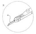
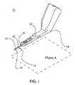
- FIG. 1is a perspective view of a tool for penetrating and creating an incision in a vessel in deployment position.
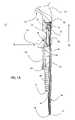
- FIG. 1Ais a side cross-sectional view of the tool.
- FIG. 2is an enlarged perspective view of the distal portion of the tool with a tip protector retracted into a needle.
- FIG. 3is an enlarged perspective view of the distal portion of the tool with the tip protector extending past the tip of the needle.
- FIG. 4is a front view of the tool.
- FIG. 5is a perspective view of the tool with the needle fully inserted into the vessel.
- FIG. 6is a perspective view of the tool with a cutting member moved forward to create the incision.
- FIG. 7is a perspective view of the tool after the cutting member has been deployed.
- a single-piece tool 10is used to rapidly create an accurate, high-quality incision of a predefined length in a perfused or non-perfused vessel.
- a needle 16is fixed to the distal end of a housing 14 of the tool 10 .
- the needle 16is a substantially cylindrical tube, but may have a different cross-section if desired.
- a single slot 25 along one side of the needle 16extends from outside the needle into the lumen of the needle 16 .
- the slot 25extends substantially parallel to the axis of the needle 16 .
- the slot 25extends in a direction not substantially parallel to the axis of the needle 16 over at least a portion of its length.
- the tip 24 of the needle 16is angled such that the slot 25 resides on the shortest side of the needle 16 , with the longest side of the needle 16 being directly opposite the slot 25 .
- the slot 25has a different placement with regards to the orientation of the needle 16 .
- the tip 24 of the needle 16may be shaped differently.
- the proximal end of the housing structure 14terminates in a handle 13 .
- the handle 13is angled at approximately 120 degrees with respect to the remaining portion of the tool 10 to enable the user to easily reach the target vessel.
- the handle 13may be angled or configured differently, or may be omitted altogether.
- a first user input featuresuch as a button 22 controls the actuation of a tip protector 18 .
- Thisis done via a cam 40 .
- the cam 40has a feature 33 at its proximal end that is slightly smaller in diameter than the inner diameter of a spring 34 .
- One end of the spring 34is connected to a surface 36 of a cavity 38 within the housing 14 .
- the cam 40itself is configured to translate within that cavity 38 .
- the other end of the spring 34holds the feature 33 .
- the coils of the spring 34act against a shoulder 35 of the cam 40 .
- the spring 34is a compression spring configured to bias the cam 40 toward the distal end of the housing 14 .
- Two flat, beveled surfaces 44 and 46are substantially parallel to each other and roughly 45 degrees from the plane A as defined in FIG. 1 .
- Plane Ais arbitrarily defined as “horizontal” and the direction perpendicular to the plane A is arbitrarily defined as “vertical” in order to describe the structure and operation of the tool 10 clearly. These conventions are solely utilized to clarify this description, and do not limit the orientation of the tool 10 in use.
- the surfaces 44 and 46instead may be oriented at a different angle from the one shown here.
- the first surface 44is located on the underside of the button 22 .
- the second surface 46is located on the front portion of the cam 40 . Prior to actuating the button 22 , the two surfaces 44 and 46 may or may not be in contact with each other.
- the surface 44contacts and slides against the surface 46 on the distal portion of the cam 40 .
- This sliding motionforces the cam 40 proximally, because the motion of the button 22 is substantially constrained to the vertical direction.
- the movement of the button 22 in the substantially vertical direction of arrow Acauses the cam 40 to move in the substantially perpendicular horizontal direction indicated by arrow B.
- the cam 42translates proximally, it compresses the spring 34 that is attached to the surface 36 at the end of the cavity 38 within the tool housing 14 .
- the two surfaces 44 and 46continue to slide against each other until the button 22 is completely depressed and the overlapping areas of the two surfaces 44 and 46 are at a maximum.
- the cam 40holds one end of a wire 42 .
- the other end of the wire 42extends distal to the cam 40 and is attached to the tip protector 18 .
- the wire 42may alternately be any rigid structure that fits within the allotted space in the housing 14 and is moveable between a first position and a second position.
- the wire 42can be made out of a variety of materials such as metal or plastic.
- the tip protector 18is held by the lumen of the needle 16 .
- the tip protector 18is extendable beyond the tip 24 of the needle 16 to prevent the sharp tip 24 of the needle 16 from contacting the back wall of the vessel after initial penetration.
- the tip protector 18is atraumatic to prevent injury to the back wall of the vessel.
- the back wall of the vesselis the wall of the vessel substantially opposite to the penetration made by the needle 16 .
- the tip protector 18has a circular cross-section with a substantially rounded end, but may have a different cross-sectional geometry if desired.
- a variety of different materialsmay be used to form the tip protector 18 , including metal, plastic, ceramic, or rubber.
- the tip protector 18may be a coating created on the surface of the wire 42 . Both the cam 40 and the wire 42 move together in a substantially linear motion to control the extension of the tip protector 18 from the tip 24 of the needle 16 .
- the tip protector 18is located on the distal end of the wire 42 such that it extends past the tip 24 of the needle 16 when the spring 34 is in its relaxed state in a first position.
- the tip protector 18is in the first position, at least partially outside but still coaxial with the lumen of the needle 16 .
- the tip protector 18is moved to a second position substantially within the lumen of the needle 16 .
- the tool 10is positioned on the target vessel 12 immediately prior to penetration.
- the cam 40moves proximally, thereby retracting the tip protector 18 into the needle 16 and exposing the sharp tip 24 .
- the useradvances the entire tool 10 such that the sharp tip 24 penetrates the vessel wall 12 .
- Vessel penetrationmay be confirmed visually by a small amount of blood or other fluids exiting the proximal end of the needle 16 .
- the button 22is then released to allow the tip protector 18 to extend beyond the sharp tip 24 of the needle 16 . This is desirable so as to prevent accidental penetration through the back wall of the vessel should the tool be advanced too far into the vessel.
- the spring 34returns to its normal, uncompressed state when the button 22 is released, thus causing the cam 40 and wire 42 to move distally and causing the tip protector 18 to extend past the tip 24 of the needle 16 .
- the tip protector 18may initially be retracted into the needle 16 and released or extended manually by the user following penetration into the vessel.
- the needle 16is substantially coaxial with the wire 42 with a gap between them to accommodate the tip protector 18 attached to the wire 42 .
- the outer diameter of the tip protector 18may be substantially equal to the inner diameter of the needle 16 , with adequate clearance between to allow the tip 18 to slide within the lumen of the needle 16 .
- a cutting member 26is held in and is moveable along the slot 25 , the slot 25 serving to guide the cutting member 26 as it moves through the vessel and creates the incision.
- the slot 25is substantially the same width as the cutting member 26 so as to maintain substantially linear movement of the cutting member 26 along the axis of the needle 16 .
- the needle 16is inserted into the vessel 12 .
- the surgeonactuates the cutting member 26 by using a second user input feature such as a slider 20 located at the distal end of the tool 10 .
- the slider 20is attached to the cutting member 26 such that moving the slider 20 translates the cutting member 26 along the slot 25 in the needle 16 .
- an arched portion 48 on the slider 20grips a tab 50 that is connected to the cutting member 26 such that linear movement of the slider 20 corresponds directly with linear movement of the cutting member 26 to create an incision in the vessel wall.
- the slider 20may directly engage the cutting member 26 in a different way, or may indirectly engage the cutting member 26 such as by a linkage.
- the cutting member 26has a nose 52 that engages the upper surface of the vessel while a sharpened edge 54 immediately beneath the nose 52 cuts through the vessel wall.
- the cutting member 26may be made out of metal, ceramic, or other material whose edge can be made sharp.
- the tab 50travels within a slot 21 in the tool housing 14 between an initial starting position and a final position. Additionally, there may be grooves 23 on either or both sides of the slot 23 to serve as tracks corresponding to features that may be present on the underside of the slider 20 to help guide the slider 20 as the surgeon creates the incision. the slider 20 is shown in the initial position.
- the slider 20is shown moved to the final position as the tool 10 is held within the vessel 12 . Since the slot 21 is of a predefined length, the incision that is created by the cutting member 20 as the slider 20 is moved from the initial position to the final position will be of a known length and no measurements are needed on the part of the surgeon prior to or during the procedure.
- the cutting member 26is shown fully deployed.
- the tool 10is then removed from the newly created incision. Where the incision is an arteriotomy performed before anastomosis, a graft vessel is attached to complete the anastomosis.
Landscapes
- Health & Medical Sciences (AREA)
- Life Sciences & Earth Sciences (AREA)
- Surgery (AREA)
- Heart & Thoracic Surgery (AREA)
- Engineering & Computer Science (AREA)
- Biomedical Technology (AREA)
- Nuclear Medicine, Radiotherapy & Molecular Imaging (AREA)
- Medical Informatics (AREA)
- Molecular Biology (AREA)
- Animal Behavior & Ethology (AREA)
- General Health & Medical Sciences (AREA)
- Public Health (AREA)
- Veterinary Medicine (AREA)
- Surgical Instruments (AREA)
Abstract
Description
Claims (9)
Priority Applications (1)
| Application Number | Priority Date | Filing Date | Title |
|---|---|---|---|
| US10/134,081US7530987B1 (en) | 2002-04-24 | 2002-04-24 | Surgical tool for creating an incision in a tubular vessel |
Applications Claiming Priority (1)
| Application Number | Priority Date | Filing Date | Title |
|---|---|---|---|
| US10/134,081US7530987B1 (en) | 2002-04-24 | 2002-04-24 | Surgical tool for creating an incision in a tubular vessel |
Publications (1)
| Publication Number | Publication Date |
|---|---|
| US7530987B1true US7530987B1 (en) | 2009-05-12 |
Family
ID=40601539
Family Applications (1)
| Application Number | Title | Priority Date | Filing Date |
|---|---|---|---|
| US10/134,081Expired - Fee RelatedUS7530987B1 (en) | 2002-04-24 | 2002-04-24 | Surgical tool for creating an incision in a tubular vessel |
Country Status (1)
| Country | Link |
|---|---|
| US (1) | US7530987B1 (en) |
Cited By (4)
| Publication number | Priority date | Publication date | Assignee | Title |
|---|---|---|---|---|
| US20060195127A1 (en)* | 2002-01-25 | 2006-08-31 | Terumo Kabushiki Kaisha | Vascular incision method |
| US20160158501A1 (en)* | 2014-12-04 | 2016-06-09 | David Farris | Percutaneous scalpel and tissue dilator |
| US9463015B2 (en) | 2011-09-09 | 2016-10-11 | Cardica, Inc. | Surgical stapler for aortic anastomosis |
| US20170056050A1 (en)* | 2015-08-24 | 2017-03-02 | Ethicon Endo-Surgery, Llc | Activation features for ultrasonic surgical instrument |
Citations (25)
| Publication number | Priority date | Publication date | Assignee | Title |
|---|---|---|---|---|
| US1087845A (en)* | 1913-07-16 | 1914-02-17 | James H Stevens | Salvarsan-needle. |
| US3545443A (en)* | 1968-09-26 | 1970-12-08 | Amir H Ansari | Suprapubic cystostomy needle |
| US3605721A (en)* | 1969-11-03 | 1971-09-20 | Ismet Hallac | Biopsy needle |
| US4471778A (en)* | 1980-11-14 | 1984-09-18 | Toye Frederic J | Apparatus and method for providing opening into body cavity or viscus |
| US4543966A (en)* | 1981-06-10 | 1985-10-01 | Downs Surgical Plc | Biopsy needle |
| US4651752A (en)* | 1985-03-08 | 1987-03-24 | Fuerst Erwin J | Biopsy needle |
| US4926877A (en)* | 1989-04-24 | 1990-05-22 | Bookwalter John R | Biopsy needle with completely closable cutting end bore |
| US5292310A (en)* | 1990-12-27 | 1994-03-08 | Inbae Yoon | Safety needle |
| US5380290A (en)* | 1992-04-16 | 1995-01-10 | Pfizer Hospital Products Group, Inc. | Body access device |
| US5545175A (en)* | 1993-06-18 | 1996-08-13 | Leonard Bloom | Disposable quarded finger scalpel for inserting a line in a patent and lock off therefor |
| US5562241A (en) | 1994-02-03 | 1996-10-08 | Ethicon Endo-Surgery, Inc. | Surgical stapler instrument |
| US5591186A (en)* | 1991-05-22 | 1997-01-07 | Wurster; Helmut | Self-cutting trocar |
| US5685856A (en)* | 1996-02-27 | 1997-11-11 | Lehrer; Theodor | Coaxial blunt dilator and endoscopic cannula insertion system |
| US5709671A (en)* | 1995-10-16 | 1998-01-20 | Ethicon Endo-Surgery, Inc. | Trocar having an improved tip configuration |
| US6113616A (en) | 1996-02-20 | 2000-09-05 | Cardiothoracic Systems, Inc. | Surgical instruments for making precise incisions in a cardiac vessel |
| US6187019B1 (en) | 1998-02-26 | 2001-02-13 | Ethicon Endo-Surgery, Inc. | Surgical anastomosis instrument |
| US6267750B1 (en)* | 1998-07-15 | 2001-07-31 | Dsu Medical Corporation | Set with angled needle |
| US6346115B1 (en)* | 1999-02-01 | 2002-02-12 | Jeffrey M. Lawrence | Sliding knife and needle assembly for making a portal for endoscopic or arthroscopic surgery |
| US6488693B2 (en)* | 2000-01-26 | 2002-12-03 | Hearport, Inc. | Vascular incisor and method |
| US6514263B1 (en) | 2000-08-30 | 2003-02-04 | Ethicon Endo-Surgery, Inc. | Helical needle and suture combination having a strain relief element |
| US6520973B1 (en) | 2000-08-30 | 2003-02-18 | Ethicon Endo-Surgery, Inc. | Anastomosis device having an improved needle driver |
| US6530932B1 (en) | 2000-08-30 | 2003-03-11 | Ethicon Endo-Surgery, Inc. | Anastomosis device having improved tissue presentation |
| US6564087B1 (en)* | 1991-04-29 | 2003-05-13 | Massachusetts Institute Of Technology | Fiber optic needle probes for optical coherence tomography imaging |
| US6716228B2 (en)* | 2000-09-30 | 2004-04-06 | Yale University | Surgical access device |
| US6786875B2 (en)* | 2000-04-18 | 2004-09-07 | Mdc Investement Holdings, Inc. | Medical device with shield having a retractable needle |
- 2002
- 2002-04-24USUS10/134,081patent/US7530987B1/ennot_activeExpired - Fee Related
Patent Citations (25)
| Publication number | Priority date | Publication date | Assignee | Title |
|---|---|---|---|---|
| US1087845A (en)* | 1913-07-16 | 1914-02-17 | James H Stevens | Salvarsan-needle. |
| US3545443A (en)* | 1968-09-26 | 1970-12-08 | Amir H Ansari | Suprapubic cystostomy needle |
| US3605721A (en)* | 1969-11-03 | 1971-09-20 | Ismet Hallac | Biopsy needle |
| US4471778A (en)* | 1980-11-14 | 1984-09-18 | Toye Frederic J | Apparatus and method for providing opening into body cavity or viscus |
| US4543966A (en)* | 1981-06-10 | 1985-10-01 | Downs Surgical Plc | Biopsy needle |
| US4651752A (en)* | 1985-03-08 | 1987-03-24 | Fuerst Erwin J | Biopsy needle |
| US4926877A (en)* | 1989-04-24 | 1990-05-22 | Bookwalter John R | Biopsy needle with completely closable cutting end bore |
| US5292310A (en)* | 1990-12-27 | 1994-03-08 | Inbae Yoon | Safety needle |
| US6564087B1 (en)* | 1991-04-29 | 2003-05-13 | Massachusetts Institute Of Technology | Fiber optic needle probes for optical coherence tomography imaging |
| US5591186A (en)* | 1991-05-22 | 1997-01-07 | Wurster; Helmut | Self-cutting trocar |
| US5380290A (en)* | 1992-04-16 | 1995-01-10 | Pfizer Hospital Products Group, Inc. | Body access device |
| US5545175A (en)* | 1993-06-18 | 1996-08-13 | Leonard Bloom | Disposable quarded finger scalpel for inserting a line in a patent and lock off therefor |
| US5562241A (en) | 1994-02-03 | 1996-10-08 | Ethicon Endo-Surgery, Inc. | Surgical stapler instrument |
| US5709671A (en)* | 1995-10-16 | 1998-01-20 | Ethicon Endo-Surgery, Inc. | Trocar having an improved tip configuration |
| US6113616A (en) | 1996-02-20 | 2000-09-05 | Cardiothoracic Systems, Inc. | Surgical instruments for making precise incisions in a cardiac vessel |
| US5685856A (en)* | 1996-02-27 | 1997-11-11 | Lehrer; Theodor | Coaxial blunt dilator and endoscopic cannula insertion system |
| US6187019B1 (en) | 1998-02-26 | 2001-02-13 | Ethicon Endo-Surgery, Inc. | Surgical anastomosis instrument |
| US6267750B1 (en)* | 1998-07-15 | 2001-07-31 | Dsu Medical Corporation | Set with angled needle |
| US6346115B1 (en)* | 1999-02-01 | 2002-02-12 | Jeffrey M. Lawrence | Sliding knife and needle assembly for making a portal for endoscopic or arthroscopic surgery |
| US6488693B2 (en)* | 2000-01-26 | 2002-12-03 | Hearport, Inc. | Vascular incisor and method |
| US6786875B2 (en)* | 2000-04-18 | 2004-09-07 | Mdc Investement Holdings, Inc. | Medical device with shield having a retractable needle |
| US6514263B1 (en) | 2000-08-30 | 2003-02-04 | Ethicon Endo-Surgery, Inc. | Helical needle and suture combination having a strain relief element |
| US6520973B1 (en) | 2000-08-30 | 2003-02-18 | Ethicon Endo-Surgery, Inc. | Anastomosis device having an improved needle driver |
| US6530932B1 (en) | 2000-08-30 | 2003-03-11 | Ethicon Endo-Surgery, Inc. | Anastomosis device having improved tissue presentation |
| US6716228B2 (en)* | 2000-09-30 | 2004-04-06 | Yale University | Surgical access device |
Cited By (11)
| Publication number | Priority date | Publication date | Assignee | Title |
|---|---|---|---|---|
| US20060195127A1 (en)* | 2002-01-25 | 2006-08-31 | Terumo Kabushiki Kaisha | Vascular incision method |
| US7727250B2 (en)* | 2002-01-25 | 2010-06-01 | Terumo Kabushiki Kaisha | Vascular incision method |
| US9463015B2 (en) | 2011-09-09 | 2016-10-11 | Cardica, Inc. | Surgical stapler for aortic anastomosis |
| US10729442B2 (en) | 2011-09-09 | 2020-08-04 | Aesculap Ag | Surgical stapler for aortic anastomosis |
| US20160158501A1 (en)* | 2014-12-04 | 2016-06-09 | David Farris | Percutaneous scalpel and tissue dilator |
| US20170056050A1 (en)* | 2015-08-24 | 2017-03-02 | Ethicon Endo-Surgery, Llc | Activation features for ultrasonic surgical instrument |
| CN108135628A (en)* | 2015-08-24 | 2018-06-08 | 伊西康有限责任公司 | For the activation features of ultrasonic surgical instrument |
| JP2018525145A (en)* | 2015-08-24 | 2018-09-06 | エシコン エルエルシーEthicon LLC | Activation mechanism of ultrasonic surgical instrument |
| US10321930B2 (en)* | 2015-08-24 | 2019-06-18 | Ethicon Llc | Activation features for ultrasonic surgical instrument |
| CN108135628B (en)* | 2015-08-24 | 2021-03-26 | 伊西康有限责任公司 | Activation features for ultrasonic surgical instruments |
| US11439424B2 (en)* | 2015-08-24 | 2022-09-13 | Cilag Gmbh International | Activation features for ultrasonic surgical instrument |
Similar Documents
| Publication | Publication Date | Title |
|---|---|---|
| US20220211406A1 (en) | Soft tissue cutting device and methods of use | |
| US6080175A (en) | Surgical cutting instrument and method of use | |
| US6488693B2 (en) | Vascular incisor and method | |
| US5976164A (en) | Method and apparatus for myocardial revascularization and/or biopsy of the heart | |
| EP2311394B1 (en) | Cannulated arthroscopic knife | |
| US8911461B2 (en) | Suture cutter and method of cutting suture | |
| US5935141A (en) | Interventional cardiology instrument controlled from an intracoronary reference | |
| US5313958A (en) | Surgical biopsy instrument | |
| US5236334A (en) | Core biopsy needle units for use with automated biopsy guns | |
| US6716222B2 (en) | Stapling and cutting in resectioning for full thickness resection devices | |
| US20130304086A1 (en) | ROBOTIC ARMS DLUs FOR PERFORMING SURGICAL TASKS | |
| US5899915A (en) | Apparatus and method for intraoperatively performing surgery | |
| US6010476A (en) | Apparatus for performing transmyocardial revascularization | |
| US6036710A (en) | Apparatus for formation of a hole in a blood vessel | |
| US6918880B2 (en) | Bipolar RF excision and aspiration device and method for endometriosis removal | |
| JP2005505340A (en) | Surgical drilling device | |
| JPH1147154A (en) | Treatment instrument for endoscope | |
| JP2001523994A (en) | Control handle for endoscope | |
| WO2003041597A1 (en) | Percutaneous cellulite removal system | |
| CN108652711B (en) | Puncture core assembly with sewing function and puncture device thereof | |
| US20220096794A1 (en) | Puncture devices, and systems and methods for accessing tissue | |
| US7530987B1 (en) | Surgical tool for creating an incision in a tubular vessel | |
| US8012164B1 (en) | Method and apparatus for creating an opening in the wall of a tubular vessel | |
| CN117503209A (en) | tissue biopsy device | |
| CN213665468U (en) | Transverse intracavity stitching instrument |
Legal Events
| Date | Code | Title | Description |
|---|---|---|---|
| AS | Assignment | Owner name:CEMTURY MEDICAL, JAPAN Free format text:SECURITY AGREEMENT;ASSIGNOR:CARDICA, INC.;REEL/FRAME:014154/0925 Effective date:20030619 Owner name:DALE ARAKI, ESQ., CALIFORNIA Free format text:SECURITY AGREEMENT;ASSIGNOR:CARDICA, INC.;REEL/FRAME:014154/0925 Effective date:20030619 | |
| AS | Assignment | Owner name:CARDICA, INC., CALIFORNIA Free format text:RELEASE BY SECURED PARTY;ASSIGNOR:VENTURE LENDING AND LEASING III, INC.;REEL/FRAME:016967/0291 Effective date:20051228 | |
| AS | Assignment | Owner name:CARDICA, INC., CALIFORNIA Free format text:RELEASE BY SECURED PARTY;ASSIGNOR:GUIDANT INVESTMENT CORPORATION;REEL/FRAME:021912/0073 Effective date:20081023 | |
| AS | Assignment | Owner name:CARDICA, INC., CALIFORNIA Free format text:RELEASE BY SECURED PARTY;ASSIGNOR:CENTURY MEDICAL, INC.;REEL/FRAME:025311/0890 Effective date:20100928 | |
| FEPP | Fee payment procedure | Free format text:PAT HOLDER NO LONGER CLAIMS SMALL ENTITY STATUS, ENTITY STATUS SET TO UNDISCOUNTED (ORIGINAL EVENT CODE: STOL); ENTITY STATUS OF PATENT OWNER: LARGE ENTITY | |
| FPAY | Fee payment | Year of fee payment:4 | |
| AS | Assignment | Owner name:DEXTERA SURGICAL INC., CALIFORNIA Free format text:CHANGE OF NAME;ASSIGNOR:CARDICA, INC.;REEL/FRAME:040590/0152 Effective date:20160518 | |
| REMI | Maintenance fee reminder mailed | ||
| LAPS | Lapse for failure to pay maintenance fees | ||
| STCH | Information on status: patent discontinuation | Free format text:PATENT EXPIRED DUE TO NONPAYMENT OF MAINTENANCE FEES UNDER 37 CFR 1.362 | |
| FP | Lapsed due to failure to pay maintenance fee | Effective date:20170512 | |
| AS | Assignment | Owner name:AESDEX, LLC, PENNSYLVANIA Free format text:ASSIGNMENT OF ASSIGNORS INTEREST;ASSIGNOR:DEXTERA SURGICAL INC.;REEL/FRAME:045870/0478 Effective date:20180214 Owner name:AESCULAP AG, GERMANY Free format text:ASSET PURCHASE AGREEMENT;ASSIGNOR:AESDEX, LLC;REEL/FRAME:045870/0567 Effective date:20180220 |