US7530985B2 - Endoscopic suturing system - Google Patents
Endoscopic suturing systemDownload PDFInfo
- Publication number
- US7530985B2 US7530985B2US10/958,801US95880104AUS7530985B2US 7530985 B2US7530985 B2US 7530985B2US 95880104 AUS95880104 AUS 95880104AUS 7530985 B2US7530985 B2US 7530985B2
- Authority
- US
- United States
- Prior art keywords
- needle
- thread
- view
- members
- endoscope
- Prior art date
- Legal status (The legal status is an assumption and is not a legal conclusion. Google has not performed a legal analysis and makes no representation as to the accuracy of the status listed.)
- Expired - Lifetime, expires
Links
Images


Classifications
- A—HUMAN NECESSITIES
- A61—MEDICAL OR VETERINARY SCIENCE; HYGIENE
- A61B—DIAGNOSIS; SURGERY; IDENTIFICATION
- A61B17/00—Surgical instruments, devices or methods
- A61B17/04—Surgical instruments, devices or methods for suturing wounds; Holders or packages for needles or suture materials
- A61B17/0467—Instruments for cutting sutures
- A—HUMAN NECESSITIES
- A61—MEDICAL OR VETERINARY SCIENCE; HYGIENE
- A61B—DIAGNOSIS; SURGERY; IDENTIFICATION
- A61B17/00—Surgical instruments, devices or methods
- A61B17/04—Surgical instruments, devices or methods for suturing wounds; Holders or packages for needles or suture materials
- A61B17/0469—Suturing instruments for use in minimally invasive surgery, e.g. endoscopic surgery
- A—HUMAN NECESSITIES
- A61—MEDICAL OR VETERINARY SCIENCE; HYGIENE
- A61B—DIAGNOSIS; SURGERY; IDENTIFICATION
- A61B17/00—Surgical instruments, devices or methods
- A61B17/04—Surgical instruments, devices or methods for suturing wounds; Holders or packages for needles or suture materials
- A61B17/0483—Hand-held instruments for holding sutures
- A—HUMAN NECESSITIES
- A61—MEDICAL OR VETERINARY SCIENCE; HYGIENE
- A61B—DIAGNOSIS; SURGERY; IDENTIFICATION
- A61B17/00—Surgical instruments, devices or methods
- A61B17/04—Surgical instruments, devices or methods for suturing wounds; Holders or packages for needles or suture materials
- A61B17/0487—Suture clamps, clips or locks, e.g. for replacing suture knots; Instruments for applying or removing suture clamps, clips or locks
- A—HUMAN NECESSITIES
- A61—MEDICAL OR VETERINARY SCIENCE; HYGIENE
- A61B—DIAGNOSIS; SURGERY; IDENTIFICATION
- A61B17/00—Surgical instruments, devices or methods
- A61B17/04—Surgical instruments, devices or methods for suturing wounds; Holders or packages for needles or suture materials
- A61B17/06—Needles ; Sutures; Needle-suture combinations; Holders or packages for needles or suture materials
- A61B17/062—Needle manipulators
- A61B17/0625—Needle manipulators the needle being specially adapted to interact with the manipulator, e.g. being ridged to snap fit in a hole of the manipulator
- A—HUMAN NECESSITIES
- A61—MEDICAL OR VETERINARY SCIENCE; HYGIENE
- A61B—DIAGNOSIS; SURGERY; IDENTIFICATION
- A61B1/00—Instruments for performing medical examinations of the interior of cavities or tubes of the body by visual or photographical inspection, e.g. endoscopes; Illuminating arrangements therefor
- A61B1/012—Instruments for performing medical examinations of the interior of cavities or tubes of the body by visual or photographical inspection, e.g. endoscopes; Illuminating arrangements therefor characterised by internal passages or accessories therefor
- A61B1/018—Instruments for performing medical examinations of the interior of cavities or tubes of the body by visual or photographical inspection, e.g. endoscopes; Illuminating arrangements therefor characterised by internal passages or accessories therefor for receiving instruments
- A—HUMAN NECESSITIES
- A61—MEDICAL OR VETERINARY SCIENCE; HYGIENE
- A61B—DIAGNOSIS; SURGERY; IDENTIFICATION
- A61B17/00—Surgical instruments, devices or methods
- A61B17/04—Surgical instruments, devices or methods for suturing wounds; Holders or packages for needles or suture materials
- A61B17/0485—Devices or means, e.g. loops, for capturing the suture thread and threading it through an opening of a suturing instrument or needle eyelet
- A—HUMAN NECESSITIES
- A61—MEDICAL OR VETERINARY SCIENCE; HYGIENE
- A61B—DIAGNOSIS; SURGERY; IDENTIFICATION
- A61B17/00—Surgical instruments, devices or methods
- A61B17/04—Surgical instruments, devices or methods for suturing wounds; Holders or packages for needles or suture materials
- A61B17/0493—Protective devices for suturing, i.e. for protecting the patient's organs or the operator
- A—HUMAN NECESSITIES
- A61—MEDICAL OR VETERINARY SCIENCE; HYGIENE
- A61B—DIAGNOSIS; SURGERY; IDENTIFICATION
- A61B17/00—Surgical instruments, devices or methods
- A61B17/04—Surgical instruments, devices or methods for suturing wounds; Holders or packages for needles or suture materials
- A61B17/06—Needles ; Sutures; Needle-suture combinations; Holders or packages for needles or suture materials
- A61B17/06066—Needles, e.g. needle tip configurations
- A—HUMAN NECESSITIES
- A61—MEDICAL OR VETERINARY SCIENCE; HYGIENE
- A61B—DIAGNOSIS; SURGERY; IDENTIFICATION
- A61B17/00—Surgical instruments, devices or methods
- A61B17/064—Surgical staples, i.e. penetrating the tissue
- A61B17/0643—Surgical staples, i.e. penetrating the tissue with separate closing member, e.g. for interlocking with staple
- A—HUMAN NECESSITIES
- A61—MEDICAL OR VETERINARY SCIENCE; HYGIENE
- A61B—DIAGNOSIS; SURGERY; IDENTIFICATION
- A61B17/00—Surgical instruments, devices or methods
- A61B17/00234—Surgical instruments, devices or methods for minimally invasive surgery
- A61B2017/00292—Surgical instruments, devices or methods for minimally invasive surgery mounted on or guided by flexible, e.g. catheter-like, means
- A61B2017/00296—Surgical instruments, devices or methods for minimally invasive surgery mounted on or guided by flexible, e.g. catheter-like, means mounted on an endoscope
- A—HUMAN NECESSITIES
- A61—MEDICAL OR VETERINARY SCIENCE; HYGIENE
- A61B—DIAGNOSIS; SURGERY; IDENTIFICATION
- A61B17/00—Surgical instruments, devices or methods
- A61B17/00234—Surgical instruments, devices or methods for minimally invasive surgery
- A61B2017/00292—Surgical instruments, devices or methods for minimally invasive surgery mounted on or guided by flexible, e.g. catheter-like, means
- A61B2017/0034—Surgical instruments, devices or methods for minimally invasive surgery mounted on or guided by flexible, e.g. catheter-like, means adapted to be inserted through a working channel of an endoscope
- A—HUMAN NECESSITIES
- A61—MEDICAL OR VETERINARY SCIENCE; HYGIENE
- A61B—DIAGNOSIS; SURGERY; IDENTIFICATION
- A61B17/00—Surgical instruments, devices or methods
- A61B17/04—Surgical instruments, devices or methods for suturing wounds; Holders or packages for needles or suture materials
- A61B17/0401—Suture anchors, buttons or pledgets, i.e. means for attaching sutures to bone, cartilage or soft tissue; Instruments for applying or removing suture anchors
- A61B2017/0445—Suture anchors, buttons or pledgets, i.e. means for attaching sutures to bone, cartilage or soft tissue; Instruments for applying or removing suture anchors cannulated, e.g. with a longitudinal through-hole for passage of an instrument
- A—HUMAN NECESSITIES
- A61—MEDICAL OR VETERINARY SCIENCE; HYGIENE
- A61B—DIAGNOSIS; SURGERY; IDENTIFICATION
- A61B17/00—Surgical instruments, devices or methods
- A61B17/04—Surgical instruments, devices or methods for suturing wounds; Holders or packages for needles or suture materials
- A61B17/0401—Suture anchors, buttons or pledgets, i.e. means for attaching sutures to bone, cartilage or soft tissue; Instruments for applying or removing suture anchors
- A61B2017/0446—Means for attaching and blocking the suture in the suture anchor
- A61B2017/0448—Additional elements on or within the anchor
- A61B2017/045—Additional elements on or within the anchor snug fit within the anchor
- A—HUMAN NECESSITIES
- A61—MEDICAL OR VETERINARY SCIENCE; HYGIENE
- A61B—DIAGNOSIS; SURGERY; IDENTIFICATION
- A61B17/00—Surgical instruments, devices or methods
- A61B17/04—Surgical instruments, devices or methods for suturing wounds; Holders or packages for needles or suture materials
- A61B17/0401—Suture anchors, buttons or pledgets, i.e. means for attaching sutures to bone, cartilage or soft tissue; Instruments for applying or removing suture anchors
- A61B2017/0446—Means for attaching and blocking the suture in the suture anchor
- A61B2017/0458—Longitudinal through hole, e.g. suture blocked by a distal suture knot
- A—HUMAN NECESSITIES
- A61—MEDICAL OR VETERINARY SCIENCE; HYGIENE
- A61B—DIAGNOSIS; SURGERY; IDENTIFICATION
- A61B17/00—Surgical instruments, devices or methods
- A61B17/04—Surgical instruments, devices or methods for suturing wounds; Holders or packages for needles or suture materials
- A61B17/0401—Suture anchors, buttons or pledgets, i.e. means for attaching sutures to bone, cartilage or soft tissue; Instruments for applying or removing suture anchors
- A61B2017/0464—Suture anchors, buttons or pledgets, i.e. means for attaching sutures to bone, cartilage or soft tissue; Instruments for applying or removing suture anchors for soft tissue
- A—HUMAN NECESSITIES
- A61—MEDICAL OR VETERINARY SCIENCE; HYGIENE
- A61B—DIAGNOSIS; SURGERY; IDENTIFICATION
- A61B17/00—Surgical instruments, devices or methods
- A61B17/04—Surgical instruments, devices or methods for suturing wounds; Holders or packages for needles or suture materials
- A61B17/0469—Suturing instruments for use in minimally invasive surgery, e.g. endoscopic surgery
- A61B2017/0472—Multiple-needled, e.g. double-needled, instruments
- A—HUMAN NECESSITIES
- A61—MEDICAL OR VETERINARY SCIENCE; HYGIENE
- A61B—DIAGNOSIS; SURGERY; IDENTIFICATION
- A61B17/00—Surgical instruments, devices or methods
- A61B17/04—Surgical instruments, devices or methods for suturing wounds; Holders or packages for needles or suture materials
- A61B17/0469—Suturing instruments for use in minimally invasive surgery, e.g. endoscopic surgery
- A61B2017/0474—Knot pushers
- A—HUMAN NECESSITIES
- A61—MEDICAL OR VETERINARY SCIENCE; HYGIENE
- A61B—DIAGNOSIS; SURGERY; IDENTIFICATION
- A61B17/00—Surgical instruments, devices or methods
- A61B17/04—Surgical instruments, devices or methods for suturing wounds; Holders or packages for needles or suture materials
- A61B17/0469—Suturing instruments for use in minimally invasive surgery, e.g. endoscopic surgery
- A61B2017/0475—Suturing instruments for use in minimally invasive surgery, e.g. endoscopic surgery using sutures having a slip knot
- A—HUMAN NECESSITIES
- A61—MEDICAL OR VETERINARY SCIENCE; HYGIENE
- A61B—DIAGNOSIS; SURGERY; IDENTIFICATION
- A61B17/00—Surgical instruments, devices or methods
- A61B17/04—Surgical instruments, devices or methods for suturing wounds; Holders or packages for needles or suture materials
- A61B17/0469—Suturing instruments for use in minimally invasive surgery, e.g. endoscopic surgery
- A61B2017/0477—Suturing instruments for use in minimally invasive surgery, e.g. endoscopic surgery with pre-tied sutures
- A—HUMAN NECESSITIES
- A61—MEDICAL OR VETERINARY SCIENCE; HYGIENE
- A61B—DIAGNOSIS; SURGERY; IDENTIFICATION
- A61B17/00—Surgical instruments, devices or methods
- A61B17/04—Surgical instruments, devices or methods for suturing wounds; Holders or packages for needles or suture materials
- A61B17/0487—Suture clamps, clips or locks, e.g. for replacing suture knots; Instruments for applying or removing suture clamps, clips or locks
- A61B2017/0488—Instruments for applying suture clamps, clips or locks
- A—HUMAN NECESSITIES
- A61—MEDICAL OR VETERINARY SCIENCE; HYGIENE
- A61B—DIAGNOSIS; SURGERY; IDENTIFICATION
- A61B17/00—Surgical instruments, devices or methods
- A61B17/04—Surgical instruments, devices or methods for suturing wounds; Holders or packages for needles or suture materials
- A61B17/06—Needles ; Sutures; Needle-suture combinations; Holders or packages for needles or suture materials
- A61B17/06004—Means for attaching suture to needle
- A61B2017/06019—Means for attaching suture to needle by means of a suture-receiving lateral eyelet machined in the needle
- A—HUMAN NECESSITIES
- A61—MEDICAL OR VETERINARY SCIENCE; HYGIENE
- A61B—DIAGNOSIS; SURGERY; IDENTIFICATION
- A61B17/00—Surgical instruments, devices or methods
- A61B17/04—Surgical instruments, devices or methods for suturing wounds; Holders or packages for needles or suture materials
- A61B17/06—Needles ; Sutures; Needle-suture combinations; Holders or packages for needles or suture materials
- A61B17/06004—Means for attaching suture to needle
- A61B2017/06028—Means for attaching suture to needle by means of a cylindrical longitudinal blind bore machined at the suture-receiving end of the needle, e.g. opposite to needle tip
- A—HUMAN NECESSITIES
- A61—MEDICAL OR VETERINARY SCIENCE; HYGIENE
- A61B—DIAGNOSIS; SURGERY; IDENTIFICATION
- A61B17/00—Surgical instruments, devices or methods
- A61B17/04—Surgical instruments, devices or methods for suturing wounds; Holders or packages for needles or suture materials
- A61B17/06—Needles ; Sutures; Needle-suture combinations; Holders or packages for needles or suture materials
- A61B17/06004—Means for attaching suture to needle
- A61B2017/06042—Means for attaching suture to needle located close to needle tip
- A—HUMAN NECESSITIES
- A61—MEDICAL OR VETERINARY SCIENCE; HYGIENE
- A61B—DIAGNOSIS; SURGERY; IDENTIFICATION
- A61B17/00—Surgical instruments, devices or methods
- A61B17/04—Surgical instruments, devices or methods for suturing wounds; Holders or packages for needles or suture materials
- A61B17/06—Needles ; Sutures; Needle-suture combinations; Holders or packages for needles or suture materials
- A61B2017/06057—Double-armed sutures, i.e. sutures having a needle attached to each end
Definitions
- the present inventionrelates to a treatment device which can be inserted into a body together with an endoscope.
- U.S. Pat. No. 5,171,258(Symbiosis Co., Ltd.) discloses a medical instrument that is applicable to a surgical operation using a laparoscope.
- This medical instrumentcomprises a pair of posts for supporting a pair of devises in order to produce a large force required to grip a thick tissue.
- the posts and devisesinterfere with each other, whereby an angle that can be formed between the devises is restricted to an angle of about 90 degrees.
- a treatment deviceis required to be a small size, nevertheless the treatment device being capable of moving a needle over a large angle, is required. Further, it is required to transmit a large force to the needle in order to securely puncture the tissue.
- the present inventionhas been made in view of the above described circumstance. It is an object of the present invention to provide an endoscopic treatment device comprising a structure for further increasing an opening/closing angle and further producing a large force.
- a treatment devicewhich is used to perform treatment in a body by being operated outside the body.
- This treatment devicecomprises a flexible member having a distal end portion that can be inserted into a body, a link mechanism which is arranged at the distal end portion of the flexible member and actuated by an operation outside the body, and a curved needle which is actuated by the link mechanism and can move in a direction to puncture a tissue and a direction to be removed from the tissue.
- an endoscopic treatment devicewhich is used together with an endoscope to perform treatment in a body by being operated outside the body.
- This endoscopic treatment devicecomprises a transmission member with a flexible structure which has a distal end portion inserted into a body and can be operated outside the body, a push rod coupled to the distal end portion of the transmission member, first and second connecting members coupled to the push rod, each of the first and second connecting members having a distal end portion and a proximal end portion rotatably coupled to the push rod, first and second arm members each having a distal end portion and a proximal end portion rotatably coupled to the distal end portion of a corresponding one of the first and second connecting members, a holding member which rotatably holds the distal end portions of the respective arm members at a predetermined interval therebetween, first and second actuating members which are integrally formed with the distal end portions of the arm members and can open/close when the transmission member actuates the first and second connecting members and
- an endoscopic treatment devicewhich includes recovery means for recovering the thread inserted into a tissue from a needle, wherein the recovery means has a lock member which detaches the needle from one of the first and second actuating members.
- an endoscopic treatment devicecomprising recovery means which is used together with an endoscope to recover a thread inserted into a tissue to perform treatment in a body by being operated outside the body, wherein the recovery means has a needle lock member which can lock a needle, and a thread lock member which can lock a thread, thereby forming needle/thread fixing means which can clamp a tissue between the needle locked to the needle lock member and the thread lock member.
- an endoscopic treatment devicecomprising a restriction mechanism which is mounted on at least one of first and second actuating members which can open/close, and restricts a movement range of one actuating member.
- an endoscopic treatment devicewhich is used together with an endoscope to perform treatment in a body by being operated outside the body.
- This endoscopic treatment devicecomprises a transmission member with a flexible structure which has a distal end portion inserted into a body and can be operated outside the body, a push rod coupled to the distal end portion of the transmission member, first and second connecting members coupled to the push rod, each of the first and second connecting members having a distal end portion and a proximal end portion rotatably coupled to the push rod, first and second arm members each having a distal end portion and a proximal end portion rotatably coupled to the distal end portion of a corresponding one of the first and second connecting members, a holding member which rotatably holds the distal end portions of the respective arm members at a predetermined interval therebetween, first and second actuating members which are integrally formed with the distal end portions of the arm members and can open/close when the transmission member actuates the first and second connecting members
- a treatment devicewhich is used together with an endoscope to perform treatment in a body by being operated outside the body.
- This treatment devicecomprises a needle which is used to puncture a living tissue and to which a thread for suturing the tissue is fixed; a recovery member capable of recovering the needle inserted into the tissue, the recovery member having an outer periphery portion at which a groove is provided and an inner hole; a guide formed in an elongated shape and capable of guiding the recover member; an elongated circular member capable of being inserted into the guide; and at least one arm provided at a distal end of the elongated circular member, wherein the recovery member is engaged with the elongated circular member when the arm and the groove are located in the guide.
- a treatment devicewhich is used together with an endoscope to perform treatment in a body by being operated outside the body.
- This treatment devicecomprises a recovery member capable of recovering a needle punctured into a tissue, the recovery member having an outer periphery portion at which a protrusion is formed; a guide formed in an elongated shape and having an inner hole, the guide being capable of guiding the recovery member; circular members having a distal end portion at which a groove has been provided, each of which is capable of being inserted into the guide; and another elongated circular member capable of being inserted into the circular member, wherein, when the protrusion and the groove are engaged with each other, the recovery member and the circular members can be integrally advanced and retracted, and the elongated circular member and the circular members can be separated from each other.
- a treatment devicewhich is used together with an endoscope to perform treatment in a body by being operated outside the body.
- This treatment devicecomprises a transmission member with a flexible structure which has a distal end portion inserted into a body and is capable of being operated outside of the body; a push rod coupled to the distal end portion of the transmission member; first and second connecting members coupled to the push rod, each of the first and second connecting members having a distal end portion and a proximal end portion rotatably coupled to the push rod; first and second arm members each having a distal end portion and a proximal end portion rotatably coupled to the distal end portion of a corresponding one of the first and second connecting members; a holding member which rotatably holds the distal end portions of the first and second arm members; first and second actuating members which are integrally formed with the distal end portions of the first and second arm members and are able to open/close when the transmission member actuates the first and second connecting members
- a suturing method using an endoscopic suturing devicecomprises:
- a treatment devicewhich is used together with an endoscope to perform treatment in a body cavity by being operated outside the body.
- This devicecomprises driving means which is inserted into the body cavity together with the endoscope and operated outside the body, an arm member which is placed in the body cavity and operated by the driving means, a connecting member which is detachably mounted on the arm member, and a needle which is used to punctuate a living tissue and to which a thread for suturing the tissue is fixed.
- the needleis detachably mounted on the connecting member.
- a treatment devicewhich is used together with an endoscope to perform treatment in a body cavity by being operated outside the body.
- This devicecomprises a transmission member with a flexible structure which has a distal end portion inserted into a body cavity and is capable of being operated outside the body, a push rod coupled to the distal end portion of the transmission member, first and second connecting members coupled to the push rod, each of the first and second connecting members having a distal end portion and a proximal end portion rotatably coupled to the push rod, first and second arm members each having a distal end portion and a proximal end portion rotatably coupled to the distal end portion of a corresponding one of the first and second connecting members, a holding member which rotatably holds the distal end portion of each of the arm members, first and second actuating members which are integrally formed with the distal end portions of the first and second arm members and are able to open/close when the transmission member actuates the first and second connecting members and
- a treatment devicewhich is used together with an endoscope to perform treatment in a body cavity by being operated outside the body.
- This devicecomprises driving means which is inserted into the body cavity together with the endoscope and operated outside the body, an arm member which is placed in the body cavity and operated by the driving means, a connecting member which is mounted on the arm member, a needle which includes a fixing portion being able to be atached and detached to and from the connecting member and is used to puncture a living tissue and to which a thread for suturing the living tissue is fixed, and an elastic member placed near the fixing portion.
- the connecting member and the needleare fixed through the elastic member.
- a treatment devicewhich is used together with an endoscope to perform treatment in a body cavity by being operated outside the body.
- This devicecomprises a transmission member with a flexible structure which has a distal end portion inserted into a body cavity and is capable of being operated outside the body, a push rod coupled to the distal end portion of the transmission member, first and second connecting members coupled to the push rod, each of the first and second connecting members having a distal end portion and a proximal end portion rotatably coupled to the push rod, first and second arm members each having a distal end portion and a proximal end portion rotatably coupled to the distal end portion of a corresponding one of the first and second connecting members, a holding member which rotatably holds the distal end portion of each of the arm members, first and second actuating members which are integrally formed with the distal end portions of the first and second arm members and are able to open/close when the transmission member actuates the first and second connecting members and
- a method of contracting a stomach by using an endoscopic treatment devicecomprises steps of placing a thread for contracting the stomach between first and second actuating members of the treatment device, inserting the treatment device combined with an endoscope into a body, fixing the thread to portions of a stomach wall by using the treatment device, and pulling the thread to contract the stomach.
- this methodfurther comprises steps of making the thread pulled to contract the stomach extend through a tube, and fixing the tube to the stomach wall in the form of a loop near the contracted thread by using the treatment device.
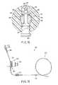
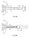
- FIG. 1is an illustrative view showing an entire configuration of an endoscopic suturing system according to a first embodiment of the present invention
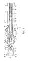
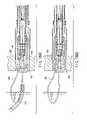
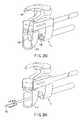
- FIG. 2is an enlarged view of an endoscope and a suturing device shown in FIG; 1 ;
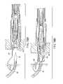
- FIG. 3is an illustrative view showing a state in which first and second actuating members of the suturing device are closed;
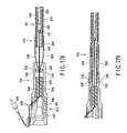
- FIG. 4is an illustrative view showing a state in which the first and second actuating members of the suturing device are opened;
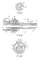
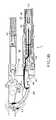
- FIG. 5is a sectional view showing an internal structure of the suturing device of FIG. 3 ;
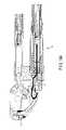
- FIG. 6is a sectional view showing an internal structure of the suturing device of FIG. 4 ;
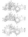
- FIG. 7is a sectional view taken along the line A-A of FIG. 5 ;
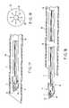
- FIG. 8is a view seen in a direction indicated by the arrow B of FIG. 4 ;
- FIG. 8Ais a view showing a suturing device when an endoscope is removed, the view being similar to FIG. 8 ;
- FIG. 9is a sectional view taken along the line C-C of FIG. 7 ;
- FIG. 10is a sectional view taken along the line D-D of FIG. 7 ;
- FIG. 11is a sectional view taken along the line E-E of FIG. 7 ;
- FIG. 12is a sectional view taken along the line F-F of FIG. 13 ;
- FIG. 13is a view seen in a direction indicated by the arrow G of FIG. 7 ;
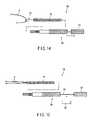
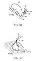
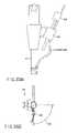
- FIG. 14is a view showing a hook of a thread-catching-device when a suture thread is hooked
- FIG. 15is a view showing a hook of a thread-catching-device when the suture thread and hook are retracted into a sheath;
- FIG. 15Ais a view showing an outer appearance of another thread-catching-device
- FIG. 15B and FIG. 15Care views showing how the thread-catching-device catches a thread by using a hook
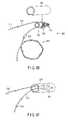
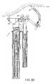
- FIG. 16is a schematic longitudinal cross section of an insert assisting device
- FIG. 17is an illustrative view showing a state in which an endoscope having a suturing device mounted thereon is housed in an insert assisting device;
- FIG. 18is an illustrative view showing a state in which the endoscope having the suturing device mounted thereon is protruded from the insert assisting device;
- FIG. 19is a view showing a modified example of a valve mounted on the insert assisting device.
- FIG. 20is a view showing the insert assisting device according to a modified example when the endoscope and the suturing device are mounted;
- FIG. 21is a view showing a state in which the endoscope and the suturing device are protruded from the insert assisting device of FIG. 20 ;
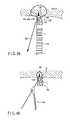
- FIG. 22 to FIG. 27each show a suturing procedure using the suturing device, wherein FIG. 22 is a view showing a state in which a curved needle is proximal to a tissue;
- FIG. 23is a view showing a state in which the curved needle punctures a tissue
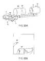
- FIG. 24is a view showing a state in which the thread-catching-device hooks the suture thread
- FIG. 25is a view showing a state in which the suture thread is retracted into a flexible tubular member together with the hook when the thread is hooked;
- FIG. 26is a view showing a state in which the thread-catching-device is pulled out from an instrument channel port
- FIG. 27is a view showing a state in which the curved needle is removed from the tissue
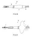
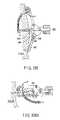
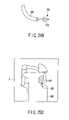
- FIG. 28is a view showing a state in which the suturing device is removed from the cavity together with the insert assisting device
- FIG. 29is a view showing a state in which a knot is fed into a body by using a knot pusher
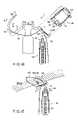
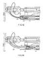
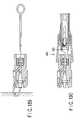
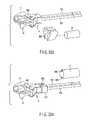
- FIG. 30is a view showing a state in which the suturing device is housed in a protect member, the figure being similar to FIG. 2 showing an endoscopic suturing system according to a second embodiment of the present invention
- FIG. 31is an illustrative view showing a state in which the suturing device is protruded in the endoscopic suturing system of FIG. 30 ;
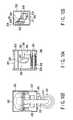
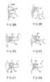
- FIG. 32 to FIG. 35are views each showing a protect member in the second embodiment, wherein FIG. 32 is a view showing a state in which a movable portion is protruded;
- FIG. 33is a view showing a state in which a moving member disengages a lock member
- FIG. 34is a view showing a state in which the movable portion is retracted
- FIG. 35is a detailed view of the lock member
- FIG. 36is an illustrative view of the protect member using an endoscopic suturing system according to a third embodiment of the present invention.
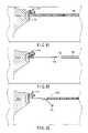
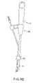
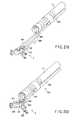
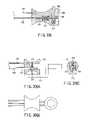
- FIG. 37 to FIG. 41each show an endoscopic suturing system according to a fourth embodiment, wherein FIG. 37 is a view showing a suturing device used therefor;
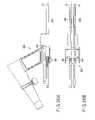
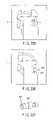
- FIG. 38is a view showing a state in which a removable needle after punctured into a tissue is engaged with a needle thread fixing device
- FIG. 39is a view showing a state in which an injury is closed by tying the suture thread
- FIG. 40is a view showing a state in which a redundant portion of the suture thread is cut by a thread cutting device
- FIG. 41is a sectional view taken along the line H-H of FIG. 37 ;
- FIG. 42is a sectional view showing a state in which sealing means is incorporated into the frontal side of the insert assisting device shown in FIG. 16 ;
- FIG. 43is a sectional view taken along the line I-I of FIG. 42 ;
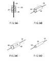
- FIG. 44is a view showing a suturing device for use in an endoscopic suturing system according to a fifth embodiment of the present invention.
- FIG. 45is a view showing a state in which a removable needle after punctured into a tissue is engaged with a needle thread fixing device
- FIG. 46is a view showing a suturing device for use in an endoscopic suturing system according to a sixth embodiment of the present invention.
- FIG. 47is a view showing a state in which a removable needle after punctured into a tissue is engaged with a needle fixing device
- FIG. 48is a view showing a state in which a knot is formed by a loop removed from an engagingly lock member when the first and second actuating members are opened;
- FIG. 49is a view showing a state in which a redundant portion of the suture thread is cut by a thread cutting device
- FIG. 50is a view showing a state in which a tissue is sutured while the tissue is pulled by a grasping forceps;
- FIG. 51is a view showing a state for use in an endoscopic suturing system according to a seventh embodiment of the present invention.
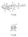
- FIG. 52is a view showing a state when a removable needle after punctured into a tissue is engaged with a needle thread fixing device
- FIG. 53is a sectional view taken along the line J-J of FIG. 52 ;
- FIG. 54is a view showing a structure by thread lock means
- FIG. 54A to FIG. 54Dare views showing various modifications of the lock means
- FIG. 55is a view showing a state in which a needle holder is removed from a tissue
- FIG. 56is a view showing a state in which a tissue is tied
- FIG. 57 to FIG. 63each show a suturing procedure using an endoscopic suturing system according to an eighth embodiment of the present invention, wherein FIG. 57 is a view showing a state in which the suturing device is proximal to a tissue to be sutured;
- FIG. 58is a view showing a state in which a removable needle after punctured into a tissue is engaged with a needle fixing device
- FIG. 59is a view showing a state in which a needle holder is pulled out from a tissue
- FIG. 60is a view showing a state in which the suturing device and endoscope are spaced from a tissue while the needle thread fixing device is left;
- FIG. 61is a view showing a state in which a tissue is tied with the suture thread
- FIG. 62is a view showing a state in which the suture thread can be separated
- FIG. 63is a view showing a state in which a redundant portion of the suture thread is cut by a thread cutting device
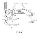
- FIG. 64is a view showing a suturing device for use in an endoscopic suturing system according to a ninth embodiment of the present invention.
- FIG. 65is a view showing a state in which a removable needle after punctured into a tissue is engaged with a needle fixing device
- FIG. 66is a view showing a tissue when the tissue is sutured
- FIG. 67 to FIG. 99each show the 10th embodiment, wherein FIG. 67 is a sectional view taken along the line A-A of FIG. 68 ;
- FIG. 68is a view showing an outer appearance of a suturing device (a view taken in the direction of an arrow B in FIG. 67 );
- FIG. 69is a view taken in the direction of an arrow C in FIG. 67 (with a partially sectional view);
- FIG. 70is a view taken in the direction of an arrow D in FIG. 69 ;
- FIG. 71is a sectional view taken along the line E-E of FIG. 69 ;
- FIG. 72is a sectional view taken along the line F-F of FIG. 69 ;
- FIG. 73is a sectional view taken along the line G-G of FIG. 69 ;
- FIG. 74is a view showing the details of the operating section of the suturing device.
- FIG. 75is a sectional view taken along the line H-H of FIG. 74 ;
- FIG. 76is a view showing an outer appearance of a pre-knot cartridge
- FIG. 77 to FIG. 80are views for explaining how a removable needle is removed by using a needle-catching-device
- FIG. 81 to FIG. 85are views showing how the removable needle is removed by using the needle-catching-device
- FIG. 86 and FIG. 87are views showing a state wherein a cover is so mounted as to prevent a pre-knot of the pre-knot cartridge from coming off the needle-catching-device;
- FIG. 88is a view showing an outer appearance of a spring for locking the removable needle mounted in the needle-catching-device
- FIG. 89is a view showing in detail how a pre-knot is formed
- FIG. 90 to FIG. 98are views showing a suturing procedure
- FIG. 99is a view showing a needle-catching-sheath as another modification of the needle-catching-sheath
- FIG. 100 to FIG. 111each show the 11th embodiment, wherein FIG. 100 is view showing an outer appearance of a suturing device (a view taken in the direction of an arrow G in FIG. 102 );
- FIG. 101is a partially sectional view of FIG. 100 ;
- FIG. 102is a sectional view taken along the line A-A of FIG. 100 ;
- FIG. 103is a view taken in the direction of an arrow B in FIG. 101 ;
- FIG. 104is a sectional view taken along the line C-C of FIG. 101 ;
- FIG. 105is a sectional view taken along the line D-D of FIG. 101 ;
- FIG. 106is a sectional view taken along the line E-E of FIG. 102 ;
- FIG. 107is a sectional view taken along the line F-F of FIG. 102 ;
- FIG. 108 to FIG. 111are views showing how the suturing device punctures the tissue
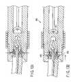
- FIG. 112 to FIG. 122each show the 12th embodiment, wherein FIG. 112 is a view showing an outer appearance of a suturing device (a view taken in the direction of an arrow G in FIG. 114 );
- FIG. 113is a partially sectional view of FIG. 112 ;
- FIG. 114is a sectional view taken along the line A-A of FIG. 112 ;
- FIG. 115is a view taken in the direction of an arrow B in FIG. 113 ;
- FIG. 116is a sectional view taken along the line C-C of FIG. 113 ;
- FIG. 117is a sectional view taken along the line E-E of FIG. 114 ;
- FIG. 118is a sectional view taken along the line F-F of FIG. 114 ;
- FIG. 119 to FIG. 122are views showing how the suturing device punctures the tissue
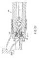
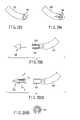
- FIG. 123 to FIG. 126Beach show the 13th embodiment, wherein FIG. 123 to FIG. 126A are views showing how the suturing device punctures the tissue;
- FIG. 126Bis a sectional view of the suturing device
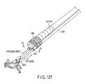
- FIG. 127 to FIG. 128Beach show the 14th embodiment, wherein FIG. 127 is a view showing a method of fixing a scope and a suturing device;
- FIG. 128Ais a sectional view of a tube holder
- FIG. 128Bis a view showing an arrangement obtained by mounting a protecting member in the arrangement shown in FIG. 127 ;
- FIG. 129 to FIG. 143each show the 15th embodiment, wherein FIG. 129 to FIG. 141 are views showing a procedure for continuously suturing the tissue;
- FIG. 142 and FIG. 143are views showing how a continuous suturing operation is performed
- FIG. 144 to FIG. 163each show the 16th embodiment, wherein FIG. 144 is a partially sectional view of a suturing device
- FIG. 145is a sectional view taken along the line A-A of FIG. 144 ;
- FIG. 146is a partial sectional view of an end loop cartridge in FIG. 158 ;
- FIG. 147 to FIG. 157are views showing the operation of a suturing device when puncturing the tissue
- FIG. 158is a view showing an outer appearance of the end loop cartridge
- FIG. 159is a view showing an outer appearance of a lock tubular member
- FIG. 160 and FIG. 161are views showing a seal structure and operating section formed on the proximal end side of the suturing device
- FIG. 162is a sectional view of the distal end portion of a thread cutting forceps used to cut a suture thread
- FIG. 163is a view showing another example of the structure of an outer sheath
- FIG. 164is a view showing a state wherein the end loop cartridge is loaded in a suturing device
- FIG. 165 and FIG. 166are views showing another form of a removable needle
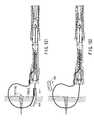
- FIG. 167is a view showing a state wherein the suturing device is mounted on an endoscope and the distal end of the suturing device is brought nearest to the distal end of the endoscope;
- FIG. 168is a view showing a state wherein the distal end of the suturing device is separated from the distal end of the endoscope;
- FIG. 169 to FIG. 171each show the 17th embodiment, wherein FIG. 169 is a partial sectional view showing a state wherein the first and second actuating members of a suturing device are open;
- FIG. 170is a partially sectional view showing a state wherein the first and second actuating members of the suturing device are closed;
- FIG. 171is a sectional view taken along the line A-A of FIG. 169 ;
- FIG. 172is a view showing a state wherein the tissue is punctured with a suturing device according to the 18th embodiment
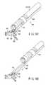
- FIG. 173 and FIG. 174are views showing a modification of a needle holder which can applied to the 10th embodiment
- FIG. 175 and FIG. 176are views showing another modification of the needle holder
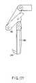
- FIG. 177is a view showing a fixing needle which can applied to the 10th embodiment and other embodiments;
- FIG. 178 and FIG. 179each show the 19th embodiment, wherein FIG. 178 is a view showing a state wherein an end loop cartridge is to be mounted in an engage tube, and FIG. 179 is a view showing a state wherein the end loop cartridge is mounted in the engage tube;
- FIG. 180 and FIG. 181each show the 20th embodiment, wherein FIG. 180 is a view showing a state wherein an end loop cartridge is to be mounted in an engage tube, and FIG. 181 is a view showing a state wherein the engage tube and a hood device are housed in a distal pipe;
- FIG. 182A to FIG. 190each show a twenty-first embodiment of the present invention, wherein FIG. 182A is an illustrative view showing a state before an end loop cartridge is assembled with a suturing device;
- FIG. 182Bis an illustrative view showing an engagingly lock member of FIG. 182A ;
- FIG. 182Cis an illustrative view showing the engagingly lock member and a circular member in an exploded manner
- FIG. 183is a sectional view showing a state in which the end loop cartridge is housed in a guide member of the suturing device;
- FIG. 184is a sectional view showing a state in which the end loop cartridge is engaged with a removable needle
- FIG. 185 and FIG. 186are sectional views showing a variety of end loop cartridges
- FIG. 187is a view showing an outer appearance of the end loop cartridge
- FIG. 188Ais an illustrative view showing a state in which the removable needle punctures a tissue
- FIG. 188Bis an illustrative view showing a state in which the end loop cartridge is engaged with the removable needle
- FIG. 188Cis an illustrative view showing a state in which the end loop cartridge removes the removable needle from a needle holding member
- FIG. 188Dshows the needle holding member that has been pulled from the tissue
- FIG. 188Edepicts the suture thread 442 that Is pulled via the hook to tie up the tissue
- FIG. 188Fshows the lock member opened or closed as the end loop cartridge is moved to the left in the drawing by using the lock member 458 and tubular member;
- FIG. 189illustrates the end loop cartridge that has been removed from the lock member
- FIG. 190is an illustrative view when the end loop cartridge is removed from the engagingly lock member
- FIG. 191is a sectional view similar to FIG. 183 , showing a twenty-second embodiment of the present invention.
- FIG. 192A to FIG. 195each show a twenty-third embodiment of the present invention, wherein FIG. 192A is an illustrative view showing a state before an end loop cartridge is assembled with a suturing device;
- FIG. 192Bis a view showing an outer appearance of the end loop cartridge
- FIG. 193is an illustrative view showing a state in which the end loop cartridge is housed in a guide member
- FIG. 194is a longitudinal sectional view of FIG. 193 ;
- FIG. 195is an illustrative view showing a state in which the end loop cartridge is removed from an engagement device
- FIG. 196 to FIG. 199each show a twenty-fourth embodiment of the present invention, wherein FIG. 196 is a longitudinal sectional view similar to FIG. 194 ;
- FIG. 197is an illustrative view showing a state before an end loop cartridge is mounted on an engagement member
- FIG. 198is a perspective view of the state shown in FIG. 197 ;
- FIG. 199is a sectional view showing a state in which the end loop cartridge is pushed inwardly from the state shown in FIG. 197 ;
- FIG. 200is a view showing an outer appearance of a hook used in the sixteenth and twenty-first embodiments
- FIG. 201shows a twenty-fifth embodiment of the present invention and is a view showing an outer appearance of a hook compared with that of FIG. 200 ;
- FIG. 202 to FIG. 208each show a twenty-sixth embodiment of the present invention, wherein FIG. 202 is a view showing a state in which a suturing device is assembled with an endoscope;
- FIG. 203is a sectional view showing a state in which the suturing device is allocated in an insert assisting device
- FIG. 204is a sectional view showing a state in which the suturing device is protruded from the insert assisting device to the outside;
- FIG. 205is an illustrative view showing a state in which the endoscope is passed through an air tight valve
- FIG. 206is an illustrative view showing a state in which a band for further enhancing air tightness is wound from the state shown in FIG. 205 ;
- FIG. 207is a sectional view taken along the line A-A of FIG. 206 , showing a state before the band is mounted;
- FIG. 208is a sectional view taken along the line A-A of FIG. 206 , showing a state in which the band has been mounted;
- FIG. 209 and FIG. 210each show a twenty-seventh embodiment of the present invention, and are a plan view and a side view of an operating section which can be applied to the sixteenth or twenty-first embodiment;
- FIG. 211is a partial sectional view of FIG. 209 ;
- FIG. 212is a view showing an outer appearance of a knob shown in FIG. 211 ;
- FIG. 213is an exploded view showing a groove formed at an outer periphery portion of the knob shown in FIG. 212 ;
- FIG. 214is a view similar to FIG. 209 , showing an operating section according to a twenty-eighth embodiment of the present invention.
- FIG. 215A and FIG. 215Bare detailed views each showing a scope holder shown in FIG. 202 ;
- FIG. 216is an illustrative view showing a state in which the operating section and scope holder are engaged with each other;
- FIG. 217 to FIG. 223Ceach show a twenty-ninth embodiment of the present invention, wherein FIG. 217 and FIG. 218 are partial sectional views each showing a scope holder;
- FIG. 219 and FIG. 220are illustrative views each showing a state in which a suturing device has been mounted on an endoscope
- FIG. 221is a view showing an outer appearance of a protrusive and recessed handle and a protrusive and recess pipe of the scope holder;
- FIG. 222is a view showing a part of an outer appearance of the scope holder shown with a plurality of tubes in their twisted state;
- FIG. 223Ais a view showing a part of an outer appearance of the scope holder shown with a plurality of tubes in their bent state;
- FIG. 223Bis a view showing the entire device for use in the twenty-first embodiment
- FIG. 223Cis a view taken in the direction of an arrow A in FIG. 223B ;
- FIG. 224 to FIG. 225Beach show a thirtieth embodiment of the present invention, wherein FIG. 224 is an illustrative view showing a state in which an endoscope is mounted on a suturing device;
- FIG. 225Ais a view showing a state in which a jig is fixed to a scope fixing portion
- FIG. 225Bis an illustrative view showing a field of view of the endoscope when the jig is used;
- FIG. 226shows a thirty-first embodiment of the present invention, and is an illustrative view showing a state in which an endoscope has been mounted on a suturing device;
- FIG. 227 and FIG. 228each show a thirty-second embodiment of the present invention, wherein FIG. 227 is an illustrative view showing a state in which an endoscope is mounted on a suturing device;
- FIG. 228is an illustrative view comparatively showing a state in which a scope fixing portion is unstable
- FIG. 229 to FIG. 231each show a thirty-third embodiment of the present invention, wherein FIG. 229 is a view showing a field of view of an endoscope in a state in which a removable needle is mounted on a needle holding member;
- FIG. 230is a view showing a field of view of the endoscope in a state in which the removable needle has been mounted from the needle holding member;
- FIG. 231is an illustrative view showing an end loop cartridge with a mark
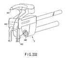
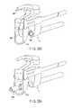
- FIG. 232 to FIG. 234each show a thirty-fourth embodiment of the present invention, wherein FIG. 232 is an illustrative view showing a part of a suturing device;
- FIG. 233is an illustrative view showing the suturing device having a second active member formed in a loop shape
- FIG. 234is a view showing a relationship between the active member of FIG. 233 and the end loop cartridge;
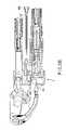
- FIG. 235shows a thirty-fifth embodiment, and is a sectional view showing a suturing device
- FIG. 236A to FIG. 237Ceach show a thirty-sixth embodiment of the present invention, wherein FIG. 236A is an illustrative view showing a needle holding member and a removable needle;
- FIG. 236B and FIG. 236Care sectional views each showing the removable needle and a thread fixing portion
- FIG. 237Ais an illustrative view showing a needle holding member and a removable needle according to a modified example
- FIG. 237B and FIG. 237Care views similar to FIG. 236B and FIG. 236C , respectively.
- FIG. 238is a sectional view showing the end loop cartridge according to the twenty-first embodiment.
- FIG. 239shows a thirty-seventh embodiment, and is a sectional view showing a state in which a center line of thread lock means allocated in an end loop cartridge has been displaced;
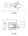
- FIG. 240 to FIG. 246show the thirty eighth embodiment, wherein FIG. 240 is a view for explaining a structure before an end loop cartridge is mounted in a suturing device;
- FIG. 241is a view showing problems associated with the end loop cartridge and a lock member in FIG. 240 ;
- FIG. 242is a view showing a lock member according to the first example of the thirty eighth embodiment.
- FIG. 243is a view showing a lock member according to the second example of the thirty eighth embodiment.
- FIG. 244Ais a view showing a state wherein a lock member according to the second example of the thirty eighth embodiment is locked to a guide member;
- FIG. 244Bis a view showing a state wherein an end loop cartridge is separated from the lock member and a hook in FIG. 244A ;
- FIG. 245is a view showing a lock member according to the fourth example of the thirty eighth embodiment.
- FIG. 246is a view showing a lock member according to the fifth example of the thirty eighth embodiment.
- FIG. 247shows, together with FIG. 248 , the thirty ninth embodiment and is a view for explaining a state wherein an endoscope on which a suturing device used in this embodiment is mounted is hooked on a scope placement site;
- FIG. 248is a view for explaining the slider of the suturing device shown in FIG. 248 ;
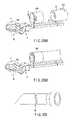
- FIG. 249shows the fortieth embodiment and is a view for explaining a removable needle used in this embodiment
- FIG. 250shows the forty first embodiment and is a view for explaining a guide member used in this embodiment
- FIG. 251shows, together with FIG. 252 , the forty second embodiment and is a view for explaining a state wherein a tissue is sutured by using the suturing device of the twenty first embodiment;
- FIG. 252is a view similar to FIG. 251 , which shows a suturing device including a groove;
- FIG. 253shows the forty third embodiment and is a view for explaining a scope fixing portion
- FIG. 254shows, together with FIG. 255A and FIG. 255B , the forty fourth embodiment and is a view for explaining a thread lock member used for this embodiment;
- FIG. 255Ais a sectional view of a caulking pipe
- FIG. 255Bis a view for explaining a state wherein a thread is fixed to an end loop cartridge by using a thread lock member
- FIG. 256shows the forty fifth embodiment and is a view for explaining an air tight valve used in this embodiment
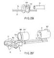
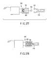
- FIG. 257shows, together with FIG. 258A to FIG. 262 , the forty sixth embodiment and is a view for explaining the relationship between an endoscope and a suturing device;
- FIG. 258Ais a view for explaining a structure immediately before a suturing device is mounted on an endoscope
- FIG. 258Bis a view for explaining a state wherein the suturing device is mounted on the endoscope
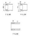
- FIG. 259is a view for explaining an insert assisting device
- FIG. 260is a view for explaining the first example of a scope fixing portion
- FIG. 261is a view for explaining the second example of a scope fixing portion
- FIG. 262is a view for explaining the third example of a scope fixing portion
- FIG. 263 to FIG. 267show the forty seventh embodiment and is a view for explaining a suturing device used in this embodiment
- FIG. 264is a view showing an engagement male member provided in place of the hook in the twenty first embodiment
- FIG. 265is a view showing an end loop cartridge and engagement male member in a guide member
- FIG. 266is a view showing a state wherein an engagement female member fitted on an engagement male member is coupled to a thread
- FIG. 267is a view for explaining a state wherein the engagement female member is fitted on the engagement male member
- FIG. 268 to FIG. 276show the forty eighth embodiment, wherein FIG. 268 is a view showing a state wherein a thread extending from an end loop cartridge is hooked on a hook provided for the engagement female member;
- FIG. 269 to FIG. 276show suturing procedures in this embodiment, wherein FIG. 269 is a view showing a state wherein a tissue is punctured with a removable needle;
- FIG. 270is a view showing a state wherein an end loop cartridge is moved and engaged with a removable needle
- FIG. 271is a view showing a state wherein the end loop cartridge is moved and the removable needle is detached from a needle holding member;
- FIG. 272is a view showing a state wherein the needle holding member is removed from a tissue
- FIG. 273is a view showing a state wherein the tissue is tied
- FIG. 274is a view showing a state wherein the free end of a lock member is separated from the end loop cartridge
- FIG. 275is a view showing a state wherein the thread and end loop cartridge are moved
- FIG. 276is a view showing a state wherein a hook is removed from the thread
- FIG. 277 to FIG. 282show the forty ninth embodiment, wherein FIG. 277 is a view showing an end loop cartridge and engagement female member used in this embodiment;
- FIG. 278is a view showing a state wherein the engagement female member is mounted on the end loop cartridge
- FIG. 279is a view showing a state wherein the end loop cartridge is pulled into a guide member
- FIG. 280is a view showing a state wherein the engagement female member and an end member of a thread are pulled into a tubular member from the positions shown in FIG. 279 ;
- FIG. 281is a view showing a state wherein the engagement female member protrudes from the tubular member
- FIG. 282is a view showing an example in which the embodiment is applied to the engagement female member shown in FIG. 266 ;
- FIG. 283 to FIG. 285show the fiftieth embodiment, wherein FIG. 283 is a view showing a case in which an end loop cartridge is housed and a suturing device;
- FIG. 284is a view for explaining a removable needle used in the embodiment in FIG. 283 ;
- FIG. 285is a view showing a modification to the case
- FIG. 286A to FIG. 288show the fifty first embodiment, wherein FIG. 286 is a view for explaining the end loop cartridge;
- FIG. 286Bis a view for explaining an end portion of the thread in FIG. 286 ;
- FIG. 287is a view for explaining a state wherein the end loop cartridge in FIG. 286 is fixed;
- FIG. 288is a view for explaining a state wherein the thread in FIG. 287 is held
- FIG. 289A to FIG. 289Dshow the fifty second embodiment, wherein FIG. 289A is a view schematically showing the distal end portion of the suturing device in FIG. 289A ;
- FIG. 289Bis a view showing a modification to the connecting portion between an active member and a needle holding member
- FIG. 289Cis a schematic sectional view of FIG. 289B ;
- FIG. 289Dis a view showing a modification to the connecting portion between a removable needle and the needle holding member
- FIG. 290 to FIG. 300Bshow the fifty third embodiment, wherein FIG. 290 is a view for explaining a needle holding member and removable needle used in this embodiment;
- FIG. 291is a view for explaining the needle holding member on which the removable needle is mounted and an end loop cartridge
- FIG. 292is a view for explaining a state wherein the needle holding member and end loop cartridge in FIG. 291 are engaged with each other;
- FIG. 293is a view for explaining a needle holding member according to a modification
- FIG. 294is a view for explaining a needle holding member according to another modification
- FIG. 295is a partially sectional view showing a state wherein an elastic material is bonded to the needle holding member shown in FIG. 290 ;
- FIG. 296Ais a view for explaining a state wherein an elastic material is mounted on a removable needle according to a modification
- FIG. 296Bis a sectional view taken along a line A-A of FIG. 296A ;
- FIG. 297Ais a partially sectional view showing a state wherein a removable needle according to another modification on which an elastic material is mounted is attached to the needle holding member;
- FIG. 297Bis a view showing a state wherein a removable needle according to still another modification on which an elastic material is mounted is attached to the needle holding member;
- FIG. 298Ais a view for explaining the needle holding member on which a removable needle according to still another modification is mounted;
- FIG. 298Bis a sectional view of the needle holding member shown in FIG. 298A ;
- FIG. 299Ais a view for explaining the needle holding member on which a removable needle according to still another modification is mounted;
- FIG. 299Bis a sectional view of the needle holding member shown in FIG. 299A ;
- FIG. 300Ais a view for explaining a removable needle and needle holding member according to still another modification
- FIG. 300Bis a view for explaining a state wherein the removable needle and needle holding member in FIG. 300A are fixed;
- FIG. 301 to FIG. 308show the fifty fourth embodiment, wherein FIG. 301 is a view for explaining a state wherein the first and second active members are open to the maximum extent;
- FIG. 302is a view for explaining a state wherein the first and second active members are slightly closed;
- FIG. 303is a view for explaining the first example in which the first and second active members are connected to corresponding driving members, respectively;
- FIG. 304is a view for explaining the second example in which the proximal ends of the two driving members to two sliders;
- FIG. 305is a view for explaining the third example in which the proximal ends of the two driving members are connected to an operating portion;
- FIG. 306A to FIG. 306Cshow the fourth example in which the proximal ends of the two driving members are connected to the operating portion, wherein FIG. 306A is a partially sectional view;
- FIG. 306Bis a sectional view taken along a line B-B of FIG. 306A ;
- FIG. 306Cis a sectional view taken along a line C-C of FIG. 306A ;
- FIG. 307is a view for explaining the fifth example in which the first and second active members are slightly closed;
- FIG. 308is a view for explaining the sixth example
- FIG. 309 to FIG. 321show the fifty fifth embodiment, wherein FIG. 309 is a view for explaining a state wherein the first and second active members are opened to press a suturing device against the tissue;
- FIG. 310is a view for explaining a state wherein the tissue is punctured at the first time
- FIG. 311is a view for explaining a state wherein the first and second active members are slightly open;
- FIG. 312is a view for explaining a state wherein the first and second active members are further open;
- FIG. 313is a view for explaining a state wherein the tissue is punctured at the second time
- FIG. 314is a view for explaining a state wherein the first and second active members are closed to a predetermined position
- FIG. 315is a detailed view of FIG. 310 ;
- FIG. 316is a detailed view of FIG. 311 ;
- FIG. 317is a detailed view of the first example
- FIG. 318is a detailed view showing a structure immediately before the first and second active members according to the first example are open;
- FIG. 319is a schematic perspective view of the first example
- FIG. 320is a detailed view of the second example
- FIG. 321is an enlarged view of part of FIG. 320 , showing a state wherein the second active member is moved;
- FIG. 322is an enlarged view of part of a state wherein the second active member is further moved
- FIG. 323 to FIG. 352show the fifty sixth embodiment, wherein FIG. 323 is a view showing an endoscope image obtained when a suturing device is mounted on an endoscope;
- FIG. 324is a view similar to FIG. 323 , showing a state wherein the mounting position of the suturing device on the endoscope is changed;
- FIG. 325is a view for explaining the first example of the fifty sixth embodiment
- FIG. 326is a view for explaining the second example
- FIG. 327is a view for explaining a state wherein the mounting position of the suturing device on the endoscope is changed from that in FIG. 326 ;
- FIG. 328is a view for explaining the third example.
- FIG. 329is a view for explaining the third example in which a sheath fixing member and scope fixing portion are mounted;
- FIG. 330is a view for explaining the fourth example
- FIG. 331is a view for explaining a state wherein the mounting position of the suturing device on the endoscope is changed from that in FIG. 330 ;
- FIG. 332is a view for explaining the fifth example
- FIG. 333is a view for explaining a state wherein the mounting position of the suturing device on the endoscope is changed from that in FIG. 332 ;
- FIG. 334is a view for explaining the sixth example
- FIG. 335is a view for explaining the seventh example
- FIG. 336is a view for explaining the eighth example.
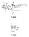
- FIG. 337is a view for explaining a modification to the eighth example.
- FIG. 338is a view for explaining a state wherein the mounting position of the suturing device on the endoscope is changed from that in FIG. 337 ;
- FIG. 339is a view for explaining the ninth example.
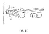
- FIG. 340is a view for explaining the tenth example
- FIG. 341is a view for explaining a state wherein the mounting position of the suturing device on the endoscope is changed from that in FIG. 340 ;
- FIG. 342is a view for explaining the eleventh example
- FIG. 343is a sectional view taken along a line A-A of FIG. 342 ;
- FIG. 344is a view for explaining the eleventh example in a state wherein an endoscope is mounted
- FIG. 345is a sectional view taken along a line A-A of FIG. 344 ;
- FIG. 346is a view for explaining a state wherein the mounting position of the suturing device on the endoscope is changed from that in FIG. 344 ;
- FIG. 347is a sectional view taken along a line A-A of FIG. 346 ;
- FIG. 348is a view for explaining the twelfth example
- FIG. 349is a view for explaining a state wherein the mounting position of the suturing device on the endoscope is changed from that in FIG. 348 ;
- FIG. 350is a view for explaining the thirteenth example
- FIG. 351is a view for explaining the fourteenth example
- FIG. 352is a view for explaining the fifteenth example
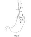
- FIG. 353 to FIG. 360show the fifty seventh embodiment, wherein FIG. 353 is a view for explaining a state wherein a thread is inserted into the stomach together with a suturing device fixed to an endoscope;
- FIG. 354Ais a view for explaining a state wherein an end loop cartridge is fixed to the stomach wall
- FIG. 354Bis a view for explaining a state wherein end loop cartridges are fixed to the stomach wall
- FIG. 355Ais a view for explaining how the first knot formed outside the body is fed into the stomach;
- FIG. 355Bis a view for explaining a state wherein the tissue is contracted in the stomach by the first knot fed into the stomach;
- FIG. 356is a view for explaining how a tube through which a thread extends is fed into the stomach together with the second knot;
- FIG. 357is a view for explaining a state wherein the second knot is moved close to the first knot
- FIG. 358is a view for explaining a state wherein the thread is cut near the second knot, and the thread is removed from the body;
- FIG. 359shows a modification and is a view for explaining a state wherein a thread is fixed throughout the inner wall of the stomach by using end loop cartridges;
- FIG. 360is a view for explaining a state wherein the stomach is contracted by the thread in FIG. 359 .
- FIG. 1 to FIG. 29show an endoscopic suturing system according to a first embodiment of the present invention.
- a gripping forcepsa scissors forceps, a hot biopsy forceps, or a rotational clipping device may be used instead of the suturing system.
- an endoscopic suturing system 1comprises an endoscope system 2 , a suturing device 3 , and a suture thread 4 .
- This suture thread 4is preferably formed like a monofilament line or stranded wire by using a material such as nylon, polyester, silk, fluoroplastic or bioabsorbable resin.
- the endoscope system 2comprises an endoscope 12 , an image processing device 14 , a light source device 15 , an observation monitor 13 , and a suction device 11 as in a generally used videoscope system.
- the endoscope 12is connected to the light source device 15 via a universal code. Then, an image signal delivered from a CCD camera 10 (refer to FIG.
- the endoscope 12is used as having an instrument channel port 6 , an endoscope of such type having two instrument channel ports may be used instead thereof.
- the CCD camera 10 , light guides 8 and 9 , instrument channel port 6 , and lens washing nozzle 11 for the CCD cameraare arranged at a distal end portion of the endoscope 12 .
- a fiberscope with its eyepiece lensmay be used instead of the videoscope using the CCD.
- the suturing device 3is removably fixed at a distal end of the endoscope 12 by a fixing member 40 , the suturing device 3 and the endoscope 12 may be structured integrally with each other instead thereof.
- the suturing device 3comprises a flexible tube 73 described later and a holding member 18 fixed at its distal end portion to hold a needle described later.
- This holding member 18is formed of: two support plate portions 18 a opposed to each other through a slit 31 (refer to FIG. 7 ); and a hole 19 (refer to FIG. 5 ) which communicates with the slit 73 between these support plate portions and an inner hole of the flexible tube 73 .
- a push rod 20is disposed retractably in an axial direction.
- first and second connecting members 22 and 23are pivoted via a pin 21 .
- the other end of each of the connecting members 22 and 23is pivoted at a proximal end portion of each of first and second arm members 24 and 25 via pins 26 and 27 , respectively.
- a first actuating member 16 formed integrally with the first arm member 24is rotatably linked with the support plate portion 18 a via a pin 28 .
- a second actuating member 17 formed integrally with the second arm member 25is rotatably linked with the support plate portion 18 a via a pin 29 .
- the pins 28 and 29each have an end portion formed by a reduced diameter portion 30 .
- the size of the slit 31 defined between the support plate portions 18 a of the holding member 18is maintained to be slightly larger than a sum of the thickness of the first actuating member 16 and the second actuating member 17 .
- the first actuating member 16 and the second actuating member 17can be moved in the slit 31 without generating a remarkable friction.
- the push rod 20is linked with an elongated flexible transmission member 71 .
- the holding member 18is linked with coils 72 and 76 that form an axial hole.
- These coils 72 and 76are linked with each other at their end faces opposed to each other by suitable means such as laser welding, blazing, soldering, adhering or the like.
- the coil 76is formed of an element wire that is more smaller in diameter than the coil 72 , whereby the suturing device 3 is formed more flexibly at its distal end side.
- These coils 72 and 76are covered with the flexible tube 73 almost all over their full lengths, and is held so as to be in intimate contact with this flexible tube 73 .
- the tube 73restricts contraction in the axial direction of the coils 72 and 76 , thereby increasing a force for opening and closing the first actuating member 16 and the second actuating member 17 .
- frontal side end portions of the tube 73 and the coil 72are fixed to an operating member main body 77 of an operating member 67 of the suturing device.
- a frontal side end portion of the transmission member 71is inserted into the operating member main body 77 , and is linked with a pipe 74 while it is inserted into the pipe 74 that is slidable relative to this operating member main body 77 .
- This pipe 74is connected to a movable member 75 by a link member (not shown). Therefore, when the movable member 75 is moved relative to the operating member main body 77 , the first actuating member 16 and the second actuating member 17 can be opened/closed via the transmission member 71 .
- the first and second arm members 24 and 25can pass through the pins 28 and 29 , and can be opened up to an angle shown in FIG. 6 .
- the length of these first and second arm members 24 and 25 each and the length of the first and second connecting members 22 and 23 eachare properly set, whereby an angle between the first and second arm members 24 and 25 can be further increased or decreased, of course. Needless to say, these members can be opened/closed within the angle range of 95 degrees or more and less than 360 degrees.
- a stopper pin 32is fixed to the push rod 20 .
- the stopper pin 32is guided to the inside of a slit 33 that extends in a longitudinal direction formed at the holding member 18 , as shown in FIG. 3 , FIG. 4 , and FIG. 7 , and the movement in the opening direction of the first and second actuating members 16 and 17 can be restricted.
- a curved needle 34is fixed to a distal end of the first actuating member 16 .
- this curved needle 34may be detachably mounted on the first actuating member 16 .
- a needle eye 5 into which a suture thread 4 can be insertedis formed at a distal end side of the curved needle 34 .
- the curved needle 34is so small in thickness as to be better punctured into a tissue.
- the second actuating member 17has bifurcated fixing arms 43 and 44 .
- Fixing needles 41 and 42are fixed to distal ends of these fixing arms 43 and 44 , respectively.
- the fixing needles 41 and 42are fixed integrally to the fixing arms 43 and 44 , these needles may be removably mounted.
- a protect member 45having holes 46 and 47 formed thereat is fixed to the first actuating member 16 by screws 48 and 49 . As shown in FIG. 5 and FIG. 6 , this protect member 45 covers a needle tip of the fixing needles 41 and 42 each when the first and second actuating members 16 and 17 are closed.
- this protect memberprevents a tissue or the like from being caught by the fixing needles 41 and 42 .
- the protect member 45may have a structure in which a recess 254 is formed in a first actuating member 218 as in the 10th embodiment (see FIG. 68 ) (to be described later).
- a channel member 35is fixed to the holding member 18 via an L shaped supporting member 39 .
- This channel member 35has: a pipe 36 formed of a comparatively hard member disposed at its distal end portion; and a tube 37 formed of a comparatively soft material tightened by a fixing thread 38 after pressed into this pipe.
- This fixing thread 38is fixed to the tube 37 by an adhesive.
- This pipe 36is inserted into a concave portion 52 (refer to FIG. 11 ) of the support member 39 , and is fixed to this support member 39 by proper means such as brazing, soldering, or bonding.
- This support member 39is formed of two elongated holes 53 through which screws 50 and 51 can pass, as shown in FIG. 11 and FIG. 13 , whereby the support member 39 can be fixed to the holding member 18 by the screws 50 and 51 so as to make it possible to adjust a position relevant to the holding member 18 .
- a protect member 54is fixed to the pipe 36 by proper means such as brazing, soldering, or bonding.
- This protect member 54covers a needle tip of the curved needle 34 when the first and second actuating members 16 and 17 are closed, and prevents the curved needle 34 from being caught by a tissue or the like.
- a thread guide 55having its axial hole through which the suture thread 4 can pass is mounted on the support member 39 .
- This thread guide 55is composed of: a pipe 57 formed of a relatively hard material; and a tube 58 formed of a relatively soft material.
- the pipe 57is fixed to the tube 58 by proper means such as press-in or bonding, for example.
- the pipe 57is fixed to the support member 39 by proper means such as brazing, soldering, or bonding.
- a thread guide 56is fixed to the holding member 18 by screws 62 and 63 .
- This thread guide 56is composed of: a pipe 59 formed of a relatively hard material; a tube 60 formed of a relatively soft material; and a plate shaped support member 61 .
- the support member 61 and the pipe 59are fixed by appropriate means such as brazing, soldering, or bonding.
- the tube 37communicates with a base 64 linked with the operating member main body 77 at its frontal side.
- a biopsy valve 69is attached to the frontal side of this base 64 .
- tubes 58 and 60communicate with holes 65 and 66 formed at the operating member main body 77 , respectively, at their frontal side.
- the suturing device 3is fixed at several positions to an insert portion 7 of the endoscope 12 by another fixing member 70 as shown in FIG. 2 .
- These fixing members 70 as wellare removably formed, whereby the suturing device 3 can be removably mounted on the insert portion 7 of the endoscope 12 .
- the suturing device 3 and the insert portion 7are formed integrally with each other, whereby they are made removable from each other.
- a thread-catching-device 68 for catching the suture thread 4comprises: a hook 79 which is movable in an axial direction and rotatable within a flexible tubular member 78 formed of a coil or the like; and an operating member 80 of the thread-catching-device for operating the hook 79 .
- the hook 79advances and retracts a grip 81 disposed movably via a pipe 83 , for example, whereby the hook can be housed in the flexible tubular member 78 or can be protruded therefrom.
- the suture thread 4can slid on this hook 79 when it is hooked by the hook 79 .
- a stopper 82which inhibits advancing movement of the grip 81 is engaged in the pipe 83 , for example, whereby the hook 79 can be locked so as not to come off the flexible tubular member 78 .
- a thread-catching-device 68is formed to have outer diameter capable of passing through the inside of the channel 35 .
- a thread-catching-device 524 shown in FIG. 15A to FIG. 15Cmay be used.
- This thread-catching-device 524has a hook 525 on which the suture thread 4 can slide as in the case with the thread-catching-device 68 .
- a guide member 526is so formed as to face the thread-catching-device 524 . As shown in FIG. 15C , the curved needle 34 is caught between the guide member 526 and the hook 525 to facilitate catching the suture thread 4 by using the hook 525 .
- FIG. 16shows an insert assisting device 84 for inserting the insert portion 7 that includes the suturing device 3 into a body.
- the insert assisting device 84comprises: a flexible tubular member 85 formed in a shape such that its distal end can be easily inserted into a body, for example, in a tapered shape; two valves 86 and 87 having circular holes 90 and 91 disposed respectively at the proximal end side of this flexible tubular member 85 ; and a base 89 which communicates with an axial hole of the flexible tubular member 85 .
- This base 89can be used to connect an aspirator (not shown) via a tube, for example, if an aspirating function is required. It is preferable that this base 89 be sealed with a cap (not shown) when it is not used.
- a plurality of slits 94are provided around a hole 93 , thereby making it possible to use a valve 92 such that an object having its external diameter larger than the hole 93 can pass.
- an insert assisting device 95 shown in FIG. 20 and FIG. 21may be used.
- This insert assisting device 95comprises: a flexible tubular member 96 ; a flexible hood member 97 disposed frontally of the flexible tubular member 96 ; and a fixing member 98 for fixing this hood member so as to be almost sealed at the insert portion 7 that includes the suturing device 3 .
- This insert assisting device 95is useful to maintain air tightness in a body. After this insert assisting device 95 has been inserted into the body, an endoscope is pushed out in a direction indicated by the arrow in FIG. 21 , whereby the suturing device 3 fixed to this endoscope can be protruded from the flexible tubular member 96 .
- sealing means 144may be provided at the proximal end side of the suturing device 3 and the endoscope 12 .
- This sealing means 144comprises: an inner tube 140 having its inner diameter through which the endoscope 12 can pass; and an outer tube 141 having its inner diameter larger than the inner tube 140 , the outer tube having this inner tube inserted therethrough.
- the outer diameter of the outer tube 141is slightly larger than the inner diameter of each of the holes 90 and 91 of the valves 86 and 87 .
- Tubes 37 , 58 , 60 , and 73 and the likeare passed through a space formed between the inner tube 140 and the outer tube 141 .
- a sealing member 142is filled in a space between these tubes.
- a space between the tube and the endoscope 12is sealed by a tape 143 . In this manner, a space between the insert assisting device 84 and the suturing device 3 and the endoscope 12 are securely sealed, and air is fed into a body, thereby preventing air leakage when the body is inflated.
- the suturing device 3 and the endoscope 12 assembled in a state shown in FIG. 2are inserted into the flexible tubular member 85 shown in FIG. 16 , and are disposed until a state shown in FIG. 17 has been obtained.
- the suture thread 4is inserted into the needle eye 5 of the curved needle 34 , and each end portion passes through the thread guides 55 and 56 each.
- the suture thread 4is held so as to be pulled out of the suturing device 3 from the holes 65 and 66 of the operating member main body 77 .
- the endoscope 12is connected to the image processing device 14 , the light source device 15 and the like ( FIG. 1 ) via a universal code. Then, while the inside of the body is observed through the monitor 13 , the flexible tubular member 85 having the suturing device 3 and the endoscope 12 housed therein is inserted into a required location in the body.
- the inside of the bodyis inflated by using an air feeding function such as an endoscope, thereby providing a space.
- the thread-catching-device 68is pulled out from the channel 35 to the outside of the body, and the suture thread 4 is pulled out from the biopsy valve 69 .
- the suture thread 4slides on the hook 79 , whereby one end portion of the suture thread 4 moves from one of the thread guides 55 and 56 into the channel 35 , and is pulled out from the channel 35 to the outside of the body together with the thread-catching-device 68 .
- the other end portion of the suture thread 4is held so as to be inserted through the other end of the thread guides 55 and 56 each.
- a knotis formed in the suture thread 4 at the outside of the body, and this knot is fed into the body several times by the knot pusher 99 as shown in FIG. 29 .
- the knot pusher 99 shown in FIG. 29has a hood shaped cylindrical member mounted on a distal end portion of the endoscope, and two holes are provided on a side face of this cylindrical member.
- any knot pusheris available for use without being limited to the shown knot pusher 99 as long as it has a structure or form such that a knot can be fed into the body.
- a knot itselfsuch as Grinch knot or Loaders knot may be formed movably. In this case, the knot can be fed into the body by using proper means.
- the first and second actuating members 16 and 17 holding the curved needle 34 and the fixing needles 41 and 42are formed integrally with the first and second arm members 24 and 25 that can be pass through the pins 28 and 29 , whereby a large opening/closing angle can be formed between the first and second actuating members 16 and 17 .
- a suturing devicehaving one or a plurality of needles capable of moving all over a sufficiently large angle required for a suturing operation.
- the coils 72 and 76 linked with the holding member 18 that rotatably supports the first and second actuating members 16 and 17are restricted from expansion and contraction by the flexible tube 73 .
- a large forcecan be transmitted via the coils 76 and 72 .
- a large force required for a suturing operationcan be transmitted to needles 34 , 41 , and 42 via the coils 76 and 72 and the first and second actuating members 16 and 17 .
- the suturing device 3is fixed to the insert portion of the endoscope 12 , thereby making it easily to do a suturing work by a flexible endoscope that has been very difficult in the prior art.
- a minimal invasive suturing procedurecan be carried out for a patient because no open surgical operation is required.
- a grasping forceps 152is inserted into the body through the instrument channel port 6 of the endoscope 12 , as shown in FIG. 50 . While the tissue is pulled by this grasping forceps 152 , the first and second actuating members 16 and 17 can be closed, and the tissue can be punctured with a curved needle 34 .
- the subsequent procedureis the same as that described with reference each of the embodiments.
- FIG. 30 to FIG. 35each show an endoscopic suturing system according to a second embodiment of the present invention.
- a variety of endoscopes described hereinafterare basically similar to those according to the above described embodiment. Like elements are designated by like reference numerals. A detailed description thereof is omitted here.
- a systemcomprises a protect member 100 mounted at a distal end portion of the insert portion 7 of the endoscope 12 , the protect member 100 covering the distal end portion of the suturing device 3 .
- This protect member 100comprises: a cylindrical fixing portion 104 , for example, that can be removably fixed at a distal end of the insert portion 7 ; and a movable portion 103 slidably mounted on the outer periphery of this fixing portion 104 .
- This movable portion 103is preferably made of a transparent resin, e.g., polycarbonate, norbornene resin, cycloolefin-based resin, or polyethylene terephthalate.
- a lock member 106 shown in FIG. 35is fixed with screws or the like inserted via mount holes 118 and 119 , for example.
- This lock member 106comprises engaging portions 116 and 117 which is disposed so as to be almost perpendicular relative to the outer periphery face of the fixing portion when fixed to the fixing portion 104 , and an inclined portion 115 which descends gradually toward a distal end from a space between these engagingly fixing portions.
- the entirety of the lock memberis formed of a resilient material such as metal or resin.
- an opening 112is formed at the outer periphery face of the fixing section 104 . In this manner, when the lock member is compressed against the outer periphery face of the fixing portion 104 , the engaging portions 116 and 117 are housed in the opening 112 , and the entirety of the lock member 106 is flattened.
- the movable portion 103has: a concave portion 120 a defined at its distal end side on an engaging wall 120 which can be engaged with the engaging portions 116 and 117 of the lock member 106 ; and a concave portion 108 a communicating with this concave portion 120 a , the concave portion being limited at its distal end side on an engaging wall 108 .
- the rear end side of these concave portions 108 a and 120 aeach is defined by the engaging wall 109 .
- In the concave portion 108 athere are housed an inclined portion 115 of the lock member 106 ; and a moving member 107 that controls engagement or disengagement between this lock member 106 and the engaging wall 120 .
- the moving member 107is formed of a hard material, for example, in a substantially cylindrical shape or flat shape. It is preferable that its length be formed to be larger than the axial dimension of the concave portion 120 a and be formed so as to be housed in the concave portion 108 a without compressing the inclined portion 115 when the engaging portions 116 and 117 and the engaging wall 120 are engaged with each other.
- Transmission members 105 and 121are extended, respectively, from an end portion of this moving member 107 .
- the transmission member 105is extended from the concave portion 120 a via a small hole that passes through the engaging wall 109 .
- the transmission member 121is extended to the inner periphery side of the movable portion 103 from a slit 110 that communicates with the concave portion 108 a , and further, is extended to the outer periphery of the fixing portion via a radial hole 113 , an axial hole 111 , and a radial hole 114 of the fixing portion 104 .
- These transmission members 105 and 121extend to the operating member main body 77 shown in FIG. 30 and FIG. 31 via a proper flexible tube (not shown), and is connected with operating member 101 and 102 of the protect member 100 .
- the moving member 107moves in the right direction, as shown in FIG. 33 .
- the moving member 107rolls over the inclined portion 115 of the lock member 106 , and thus, the engaging portions 116 and 117 are housed in the opening 112 , and are disengaged from the engaging wall 120 .
- the movable portion 103can move to the rear end side, i.e., to the right side shown in the figure. Further, when the operating member 101 of the protect member 100 is pulled, the moving member 107 abuts against the engaging wall 109 , as shown in FIG.
- the lock member 106abuts against the inner periphery face at both sides of the slit 110 formed at the movable portion 103 .
- the movable member 107moves to the left side, and is engaged with the engaging wall 108 .
- the movable portion 103moves to the left side together with the moving member 107 .
- the engaging wall 120exceeds the opening 112 , the lock member 106 returns to a state shown in FIG. 32 by its resilience. Then, the engaging portions 116 and 117 are protruded again from the outer periphery face of the fixing portion 104 , whereby the movement in the left direction of the movable portion 103 can be restricted.
- the above described protect member 100is mounted on the suturing device and endoscope assembled as in the above described embodiment, and then, the operation member 102 of the protect member 100 is pulled. In this manner, the moving portion 103 is protruded at its distal end side and comes into a state shown in FIG. 30 . In this state, the moving portion is inserted into the body while the inside of the body is observed through the endoscope 12 .
- the moving portion 103is protruded in a state shown in FIG. 30 by pulling the operating member 102 of the protect member 100 . In this state, the suturing device and endoscope is removed from the body.
- the moving portion 103 of the protect member 100moves in an axial direction.
- the outer diameter of the devicecan be reduced in addition to advantageous effect of the first embodiment. Furthermore, operation can be simplified.
- FIG. 36shows a protect member 122 used for an endoscopic suturing system according to a third embodiment of the present invention.
- the protect member 122comprises: a fixing portion 124 fixed to a distal end portion of an insert portion 7 ; and a movable portion 123 that can slide on this fixing portion 124 .
- An externally sealed annular space 128is formed between these fixing portion and movable portion.
- a base 125 communicating with the annular space 128is mounted at the outer periphery of the movable portion 123 , a fluid 127 can be poured into or discharged from the annular space 128 .
- This fluid 27may be liquid or gas.
- the movable portion 123slides to the right side on paper.
- the fluid 127is discharged from the annular space 128 by setting a fluid pouring device 129 to a negative pressure, the movable portion 123 can slide to the left side.
- FIG. 37 to FIG. 41each show an endoscopic suturing system according to a fourth embodiment of the present invention.
- a needle holder 132is fixed to a first actuating member 16 of a suturing device 3 , and a removable needle 131 is removably connected to a distal end of the needle holder 132 .
- This removable needle 131has a shaft portion 138 , and one end of a suture thread 130 is fixed to a distal end of the shaft portion 138 .
- the needle holder 132has a groove 137 opened along almost all the full length at the inner periphery side, as shown in FIG. 41 , and the suture thread 130 is removably extended inside of the groove 137 .
- this suture thread 130extends to the frontal vicinity of the endoscope through thread lock means 135 formed at a needle thread fixing device 133 .
- This thread lock means 135is formed so that the suture thread 130 can be moved arbitrarily in a direction indicated by the arrow B, i.e., in a direction in which the suture thread is retracted.
- the lock means 135is formed so that the suture thread cannot be moved in a direction indicated by the arrow A, i.e., in a direction in which the suture thread is advanced.
- needle lock means 134capable of engaging a removable needle 131 as well is formed at the needle thread fixing device 133 . It is preferable that this needle lock means 134 be formed of a resilient member or the like.
- this needle thread fixing device 133is removably mounted on a distal end of a needle fixing device main body 139 .
- This needle thread fixing device main body 139can be inserted into a body via a suitable channel 35 .
- the fixing devicecan be fixed to be grasped by a suitable device such as a grasping forceps, for example.
- the removable needle 131 and needle thread fixing device 133 described aboveare at least partly made of a biocompatible metal such as stainless steel, pure titanium or titanium alloy, a biocompatible resin such as polyimide, poly(etheretherketone) (PEEK), polysulfon, liquid crystal polymer, or polyamide, a biocompatible ceramic material such as alumina, silicon nitride, or the like.
- a biocompatible metalsuch as stainless steel, pure titanium or titanium alloy
- a biocompatible resinsuch as polyimide, poly(etheretherketone) (PEEK), polysulfon, liquid crystal polymer, or polyamide, a biocompatible ceramic material such as alumina, silicon nitride, or the like.
- the suture thread 130is formed like a monofilament line or stranded wire by using a material such as nylon, polyester, silk, fluoroplastic or bioabsorbable resin.
- This endoscopic suturing systemcan be used as follows.
- the suturing device 3is inserted into a body while its distal end portion is protected by the insert assisting devices 84 and 95 according to the first embodiment described above; a protect member 100 according to the second embodiment; or alternatively, a protect member 122 or the like according to the third embodiment.
- the inside of the bodycan be observed through the endoscope 12 as in the above described embodiment.
- the removable needle 131 after puncturedis protruded from the tissue. Thereafter, the removable needle 131 is inserted into the needle lock means 134 of the needle thread fixing device 133 by pushing out the needle fixing device main body 139 toward the front end side, and is latched thereby.
- the needle thread fixing main body 139is advanced toward the tissue while an end portion of the suture thread 130 disposed at the outside of the body is pulled frontally. In this manner, a loop of the suture thread 130 is contracted, and the tissue is tied until a state shown in FIG. 40 has been obtained.
- a redundant suture thread 130is cut by a thread cutting device 136 .
- the needle thread fixing device 133 left in the bodycan be removed during thread removal.
- FIG. 44 and FIG. 45each show a fifth embodiment of the present invention.
- This fifth embodimentis basically similar to the above-described fourth embodiment, and is different therefrom in the point below.
- the needle thread fixing device 133is removable mounted on a holding member 145 formed at the second actuating member 17 .
- the needle thread fixing device 133 described aboveare at least partly made of a biocompatible metal such as stainless steel, pure titanium or titanium alloy, a biocompatible resin such as polyimide, poly(etheretherketone) (PEEK), polysulfon, liquid crystal polymer, or polyamide, a biocompatible ceramic material such as alumina, silicon nitride, or the like.
- a biocompatible metalsuch as stainless steel, pure titanium or titanium alloy
- a biocompatible resinsuch as polyimide, poly(etheretherketone) (PEEK), polysulfon, liquid crystal polymer, or polyamide
- a biocompatible ceramic materialsuch as alumina, silicon nitride, or the like.
- This endoscopic suturing systemcan be used as follows.
- the suturing device 3When the suturing device 3 is inserted into a body, its distal end portion is particularly protected by the insert assisting devices 84 and 95 , protect member 100 , protect member 122 or the like according to the above described embodiment, for example.
- the needle thread fixing device 133is mounted on the second actuating member 17 , thus making it unnecessary to use a thread fixing device main body 139 or an ordinary grasping forceps and the like, for example.
- the first actuating member 16 and the second actuating member 17are closed so as to press the removable needle 131 and fixing needles 41 and 42 against a suture site, and the removable needle 131 is punctured into a tissue.
- the removable needle 131 protruded from a tissue after puncturedis inserted into the needle lock means 134 of the needle thread fixing device 133 held at the holding member 145 , and is engaged therewith.
- FIG. 46 to FIG. 49each show a sixth embodiment.
- the sixth embodiment as wellis basically similar to the fourth embodiment, and is different therefrom in the point below.
- engagingly lock members 146for holding at least one loop formed in advance at the suture thread 130 made of the same material as that in the first embodiment are provided at the second actuating member 17 .
- These engagingly lock members 146are formed of a resilient element in a claw shape, and is fixed so that two of these lock members are opposed to the remaining two members at a site opposed to the first actuating member 16 .
- a part of the suture thread 130is hooked by these engagingly lock members 146 , and two large loops 148 , for example, are formed.
- the removable needle 131can pass through the inside of these large loops 148 .
- At least one loop 149 for forming a knot described lateris formed at the periphery of the suture thread 130 that forms the large loop 148 and a knot like a pre-knot 232 shown in, for example, FIG. 89 (to be described later) is formed.
- a needle fixing device 150comprises: needle fixing means 147 capable of being engaged with the removable needle 131 ; and a tubular member 151 to which this needle fixing mans is fixed.
- This needle fixing device 150is formed so that the device can be inserted into a suitable channel 35 .
- the needle fixing device 150may be fixed onto the suturing device 3 . In this case, a position at which the needle fixing device 150 corresponds to a position at which the removable needle 131 can be engaged with the needle fixing means 147 .
- This endoscopic suturing systemcan be used as follows.
- the suturing device 3When the suturing device 3 is inserted into a body, as in the above described embodiment, the device is protected by the above described insert assisting devices 84 and 95 , protect member 100 , a protect member 122 or the like, for example.
- the removable needle 131 after puncturedis protruded from the tissue. Thereafter, the tubular member 151 is pushed out toward the front end side, the removable needle 131 is inserted into the needle lock means 147 of the needle thread fixing device 150 held on the tubular member 151 , and is latched thereby.
- a redundant suture thread 130is cut by a thread cutting device 136 .
- This system according to the sixth embodimentprovides advantages that are similar to those according to the above described fourth embodiment. In addition, there is no need for keeping any member except the suture thread 130 in the body.
- a grasping forceps 152when a tissue is sutured, a grasping forceps 152 , for example, can be inserted into a body through the instrument channel port 6 of the endoscope 12 as shown in FIG. 50 . While the tissue is pulled by this grasping forceps 152 , the first and second actuating members 16 and 17 are closed, thereby making it possible to puncture the removable needle 131 into the tissue.
- the subsequent procedureis similar to that described with respect to the respective embodiments.
- FIG. 51 to FIG. 56each show a seventh embodiment of the present invention.
- a structure of the suturing device 3is different from that according to the above described fourth embodiment.
- a needle thread fixing device 153is disposed instead of the needle thread fixing device 133 in the above described embodiment.
- the needle thread fixing device 153comprises thread lock means 155 and needle lock means 154 .
- This thread lock means 155is composed of a resilient tubular member having its small axial hole, and the suture thread 156 is inserted into this axial hole so as to be pressed into the hole. In this manner, the thread lock means 155 can engagingly lock the suture thread 156 at an arbitrary position.
- This thread lock means 155can be formed of a silicon tube or the like, for example.
- a reinforce member 200such as a PTFE resin based tube may be disposed coaxially of the thread lock means 155 , as shown in FIG. 54 .
- the thread lock means 155may be modified into a thread lock means 565 as shown in FIG. 54A .
- the thread lock means 565is comprised of an elastic member 566 and tubular member 567 .
- the tubular member 567is arranged on the outer surface of the elastic member 566 and has at least one recess formed by an outer force to increase the sliding resistance between the thread 156 and the elastic member 566 . This makes it possible to increase the tying force in a suturing operation.
- FIG. 54B to FIG. 54Dshow arrangements in which the tubular member 567 are deformed in different manners.
- FIG. 54Bshows an arrangement in which a plurality of recesses are formed in the tubular member 567 in the longitudinal direction.
- FIG. 54Cshows an arrangement in which a recess is formed in a direction perpendicular to the longitudinal direction of the tubular member 567 .
- FIG. 54Dshows an arrangement in which the tubular member 567 is swaged to uniformly and radially apply a pressure to the elastic member 566 .
- a loop portion 158is formed at the proximal end of the suture thread 156 .
- This loop portion 158is removably engaged with an engaging portion 163 .
- This engaging portion 163is fixed to a transmission member 165 , and is arranged retractably in a coil 164 .
- the proximal end portion of the transmission member 165is linked with an operating member (not shown) which is operable at the outside of the body. This operating member is advanced or retracted, whereby the engaging portion 163 can be advanced or retracted along the coil 164 .
- a channel 160 through which the coil 164 is insertedhas a flexible tubular member 162 and a receiving portion 161 fixed to a distal end thereof.
- a needle thread fixing device 153is held via this receiving portion 161 .
- an inclined portion 167is formed at needle lock means 154 .
- an inclined portion 169is formed similarly at a removable needle 157 as well.
- the needle lock means 154 and the removable needle 157are hardly removed from each other while they are engaged with each other via these inclined portions 167 and 169 .
- a through hole 170opened on a tapered face at a distal end through an axial portion of the removable needle 157 . This through hole 170 is formed to have a stepped structure. As shown in FIG.
- a knot 166 formed at the other end of the suture thread 156is housed in this through hole 170 , and this knot 166 can be engaged at a stepped portion so as not to move to the other end side.
- this knot 166can be fixed to the removable needle 157 by a suitable bonding agent.
- a groove 168 similar to that shown in FIG. 41is formed at a needle holder 159 that holds this removable needle 157 , a groove 168 similar to that shown in FIG. 41 is formed, and a suture thread 156 can be removed from the needle holder 159 .
- the removable needle 157 and needle thread fixing device 153 described aboveare at least partly made of a biocompatible metal such as stainless steel, pure titanium or titanium alloy, a biocompatible resin such as polyimide, poly(etheretherketone) (PEEK), polysulfon, liquid crystal polymer, or polyamide, a biocompatible ceramic material such as alumina, silicon nitride, or the like.
- a biocompatible metalsuch as stainless steel, pure titanium or titanium alloy
- a biocompatible resinsuch as polyimide, poly(etheretherketone) (PEEK), polysulfon, liquid crystal polymer, or polyamide, a biocompatible ceramic material such as alumina, silicon nitride, or the like.
- the suture thread 156is formed like a monofilament line or stranded wire by using a material such as nylon, polyester, silk, fluoroplastic or bioabsorbable resin.
- This endoscope suture systemcan be used as follows.
- the suturing device 3When the suturing device 3 is inserted into a body, the suturing device 3 is inserted while its distal end portion is particularly protected as in the above described embodiment.
- the needle 157protrudes from a tissue. Then, the coil 164 is pushed out to the forward side, the removable needle 157 is inserted into needle lock means 154 of the needle thread fixing device 153 , and is latched therewith.
- a transmission member 165is pulled to the proximal end side by an operating member (not shown), and a tissue is tied until a state shown in FIG. 56 has been obtained. Then, a distal end portion of the transmission member 165 is protruded from the coil 164 , and the loop portion 158 is removed from the engaging portion 163 .
- a redundant thread 156is cut by a thread cutting device 136 .
- a length of the suture thread 156may be short. Thus, a suturing operation is further facilitated.
- FIG. 57 to FIG. 63each show an endoscopic suturing system according to an eighth embodiment of the present invention.
- a needle thread fixing device 171is removably attached to a second actuating member 17 instead of the holding member 145 according to the fifth embodiment (refer to FIG. 44 ).
- Needle fixing means 177is formed at the needle thread fixing device 171 .
- One end of a suture thread 172is fixed to this needle thread fixing device 171 .
- the other end of this suture threadis extended into a coil 164 via thread lock means 173 similar to that according to the seventh embodiment, and a loop section 174 is formed.
- a needle holder 178 that holds the removable needle 175 at its distal end portionis fixed to a first actuating member 16 .
- One end of the other suture thread 176is fixed to this removable needle 175 , the other end of this suture thread as well is extended in the coil 164 via thread lock means 173 , and a loop portion 174 is formed. These loop portions 174 are engaged with an engaging portion 163 of a transmission member 1 . 65 as in the seventh embodiment.
- a suturing operation using this endoscope systemis carried out as follows.
- the suturing device 3is inserted into a body while its distal end portion is particularly protected by the insert assisting devices 84 and 95 , protecting member 100 , protect member 122 or the like.
- the removable needle 175 after puncturedis inserted into needle fixing means 177 of the needle thread fixing device 171 held at a predetermined position, and is engaged therewith.
- the transmission member 165is pulled by an operating member (not shown) in a state shown in FIG. 60 , a tissue is tied by the suture thread 176 until a state shown in FIG. 61 has been obtained. Then, as shown in FIG. 62 , a distal end portion of the transmission member 165 is pushed out from the coil 164 . The loop portion 174 is removed from the engaging portion 163 of the transmission member. Only the loop portion 174 of one suture thread can be pulled if necessary.
- the removable needle 157 and needle thread fixing device 171 described aboveare at least partly made of a biocompatible metal such as stainless steel, pure titanium or titanium alloy, a biocompatible resin such as polyimide, poly(etheretherketone) (PEEK), polysulfon, liquid crystal polymer, or polyamide, a biocompatible ceramic material such as alumina, silicon nitride, or the like.
- a biocompatible metalsuch as stainless steel, pure titanium or titanium alloy
- a biocompatible resinsuch as polyimide, poly(etheretherketone) (PEEK), polysulfon, liquid crystal polymer, or polyamide, a biocompatible ceramic material such as alumina, silicon nitride, or the like.
- the suture thread 172is formed like a monofilament line or stranded wire by using a material such as nylon, polyester, silk, fluoroplastic or bioabsorbable resin.
- a length of the suture threads 172 and 176each may be short. Thus, a suturing operation is further facilitated.
- FIG. 64 to FIG. 66each show an endoscopic suturing system according to a ninth embodiment of the present invention.
- the ninth embodimentis different from the eighth embodiment in the point below.
- a first actuating member 190is disposed at needle holders 179 and 180 each mounting removable needles 184 and 185 each.
- a groove opened inwardlyis extended at these needle holders 179 and 180 each, as shown in FIG. 41 .
- one of the suture threads 186 and 187 eachis fixed to the two removable needles 184 and 185 each in a manner similar to the seventh embodiment.
- a needle fixing device 181is removably mounted on the second actuating member 191 .
- Needle lock means 182 and 182 for engaging the removable needles 184 and 185are formed at the needle fixing device 181 .
- the other ends of the suture threads 186 and 187are extended into the coil 164 via thread lock means 188 similar to the thread lock means 155 according to the seventh embodiment, and a loop portion 189 is formed.
- This loop portion 189 as wellis engaged with the engaging portion 163 of the transmission member 165 as in the seventh embodiment.
- the removable needles 184 and 185 and needle thread fixing device 181 described aboveare at least partly made of a biocompatible metal such as stainless steel, pure titanium or titanium alloy, a biocompatible resin such as polyimide, poly(etheretherketone) (PEEK), polysulfon, liquid crystal polymer, or polyamide, a biocompatible ceramic material such as alumina, silicon nitride, or the like.
- a biocompatible metalsuch as stainless steel, pure titanium or titanium alloy
- a biocompatible resinsuch as polyimide, poly(etheretherketone) (PEEK), polysulfon, liquid crystal polymer, or polyamide, a biocompatible ceramic material such as alumina, silicon nitride, or the like.
- the suture threads 186 and 187are formed like a monofilament line or stranded wire by using a material such as nylon, polyester, silk, fluoroplastic or bioabsorbable resin.
- a suturing operation using this endoscope systemis carried out as follows.
- the suturing device 3is inserted into a body while its distal end portion is protected by the insert assisting devices 84 and 95 , protect member 100 , protect member 122 or the like as in the above described embodiments each.
- the first and second actuating members 190 and 191are closed so as to press the needle lock means 182 and 183 and the removable needles 184 and 185 against a suture site, and the removable needles 184 and 185 are punctured into a tissue.
- the removable needles 184 and 185 after puncturedis inserted into the needle lock means 182 and 183 of the needle fixing device 181 held at a predetermined position, and is engaged therewith.
- thread lock means 188is pushed against a tissue, an engaging portion 163 is pulled via the transmission member 165 , and the tissue is tied. Then, the engaging portion 163 is pushed out from the coil 164 , and the loop portion 189 is removed.
- the tying forcemay be adjusted with a length of one suture thread 192 instead of the two suture threads 186 and 187 .
- measuressuch as thread lock means 188 , the engaging portion 163 , the coil 164 , the transmission member 165 , the loop portion 189 and the like become unnecessary.
- the two suture threads 186 and 187can be sutured at the same time by the two removable needles 184 and 185 .
- FIG. 67 to FIG. 99show the 10th embodiment.
- the 10th embodimentdiffers from the first to third embodiments in the following points.
- the embodimentuses a pre-knot cartridge 365 like the one shown in FIG. 76 , FIG. 86 , and FIG. 87 .
- This pre-knot cartridge 365is comprised of a removable needle 213 , suture thread 214 , needle-catching-device 212 , flexible tubular member 215 , and the like.
- the suture thread 214is inserted into a hole 366 of the removable needle 213 and has a stopper 272 at its distal end face so as not to come off the removable needle 213 .
- an end face of a threadis rounded by heat.
- a peripheral portion of the stopper 272may be coated with an adhesive or the hole 366 may be caulked.
- a knotmay be formed at the end face of the thread and thermally molded by a mold which can be divided into two parts and forms a spherical surface.
- a pre-knot 232is formed in the suture thread 214 on the surface of the needle-catching-device 212 .
- the pre-knot 232is preferably tied in the form of a Roeder knot as shown in FIG. 89 , which can slide.
- the suture thread 214is also slidably inserted into the flexible tubular member 215 .
- the suture thread 214is formed into a loop 273 on the proximal end side.
- the pre-knot 232is pressed by a cover 274 so as not to come off the needle-catching-device 212 before the use of the pre-knot cartridge 365 .
- a needle-catching-sheath 211is comprised of a distal tip 249 , a flexible tubular member 247 , a flexible rod 248 inserted into the inner hole of the flexible tubular member 247 , and the like.
- a female screw 250is formed on the distal tip 249 .
- the flexible rod 248is fixed to the other end of the distal tip 249 .
- the flexible rod 248prevents the expansion of the flexible tubular member 247 upon application of a force.
- a needle-catching-sheath 527like the one shown in FIG. 99 may be used.
- the needle-catching-sheath 527is comprised of a distal tip 528 , a flexible tubular member 529 (made of, for example, a flat coil), a connecting member 530 which connects the flexible tubular member 529 to the flexible tubular member 531 , a connecting member 532 connected to a handle 533 on the proximal end side of the flexible tubular member 531 , a buckling preventing means 536 that partly covers the flexible tubular member 531 and connecting member 532 by thermal contraction, a stylet 534 for preventing the elongation of the flexible tubular member 529 and flexible tubular member 531 having both ends connected to the distal tip 528 and connecting member 532 , a flexible tubular body 535 (e.g., a tube made of fluoroplastic) fitted on the outer surface of the flexible tubular member 529 by
- the needle-catching-sheath 527has the flexible tubular body 535 . Even if, therefore, a suturing operation to be described later ( FIG. 90 to FIG. 98 ) is performed after the pre-knot 232 is placed on the flexible tubular body 535 , the thread is not caught between windings forming the flexible tubular member 529 .
- the flexible tubular body 535allows the thread to slide more smoothly than a coil, it facilitates removing the pre-knot 232 from the needle-catching-sheath as shown in FIG. 94 and FIG. 95 .
- a channel member 367is comprised of a distal pipe 233 , a tube 245 fixed to the distal pipe 233 , and the like, and fixed to a holding member 223 through a support member 234 .
- Holes 368 and 369having different diameters are formed in the distal pipe 233 .
- the diameter of the hole 369is designed to be slightly larger than the outer diameters of the needle-catching-sheath 211 and needle-catching-device 212 and smaller than the outer diameter of the pre-knot 232 .
- the needle-catching-sheath 211is inserted into the distal pipe 233 through the inner hole of the channel member 367 having almost the same diameter as that of the hole 369 .
- the needle-catching-sheath 211 as a constituent element of the pre-knot cartridge 365is detachably connected to the distal end of the needle-catching-sheath 211 with screws.
- the needle-catching-device 212is detachably connected to the distal tip 249 with screws and loaded into the hole 368 .
- the removable needle 213 of the pre-knot cartridge 365is detachably fixed to a needle holder 216 , as shown in FIG. 69 .
- the suture thread 214is placed in a groove 217 formed in the needle holder 216 .
- a slit 537may be formed in the needle holder 216 .
- the formation of such a slitgives elasticity to the fitting portion between the needle holder 216 and the removable needle 213 , thereby forming a press-fitting structure that prevents the removable needle 213 from easily coming off the needle holder 216 .
- the needle-catching-device 212is comprised of a needle-catching-body 275 , inserting member 276 , and spring 277 .
- the removable needle 213is inserted into an infundibular recess part 278 of the inserting member 276 and spreads the spring 277 (see FIG. 88 ).
- the spring 277returns to its original shape and comes into contact with a contact face 370 formed on the removable needle 213 , as shown in FIG. 79 . This makes it possible to lock the removable needle 213 to the needle-catching-device 212 , as shown in FIG. 80 .
- the needle holder 216has a taper 253 to reduce the resistance produced when it punctures the tissue.
- an operating section 255 of the suturing deviceis arranged on the proximal end side of flexible tubular members 225 and 226 and transmission member 224 .
- the operating section 255incorporates a ratchet mechanism.
- a button 261is pressed as shown in FIG. 74
- the ratchet mechanismis released to allow a slider 257 to be freely pushed and pulled.
- a stopper 267 formed on the button 261is unlocked from an engage part 268 formed on the slider 257 , and an engage part 262 that has been biased by a spring 263 is pressed downward.
- the engage part 262engages with a burr member 260 formed in an operating section body 256 .
- the slider 257can move only to the right. This inhibits first and second active members 218 and 219 from moving in a direction to open.
- the flexible tubular member 215 of the pre-knot cartridge 365is pressed into a recess 241 of a holder 240 fixed to the tube 245 .
- the flexible tubular member 215is formed from a flexible resin member such as a silicone member, the suture thread 214 can slide with respect to the flexible tubular member 215 even while the flexible tubular member 215 is pressed in the recess 241 .
- the structures of the needle-catching-device 212 , removable needle 213 , and needle holder 216 in this embodimentmay be changed into those shown in FIG. 81 to FIG. 85 .
- a needle-catching-device 283is comprised of a needle-catching-body 279 , inserting member 280 , spring 281 , and the like.
- a removable needle 364is inserted into an infundibular recess part 282 of the inserting member 280 and spreads the spring 281 (see FIG. 88 ).
- the spring 281returns to its original shape, as shown in FIG. 83 .
- the spring 281engages with a recess 371 formed in at least part of the removable needle 364 .
- the spring 281 including the removable needle 364moves until it comes into contact with a contact face 372 formed on the inserting member 280 .
- the movement of the spring 281 in a direction to spreadis restricted by the wall of an engage part 285 formed on the inserting member 280 , and hence the removable needle 364 can be locked to the needle-catching-device 283 .
- the removable needle 364has the recess part 371 to reduce the resistance produced when it punctures the tissue.
- a slit 538may be formed in the needle holder 216 without the taper 253 to form a press-fitting structure in which the fitting between the removable needle 364 and the needle holder 216 is not easily released.
- a suturing procedurewill be described with reference to FIG. 90 to FIG. 97 .
- a suturing device 210 protected by the insert assisting devices 84 and 95 in the first embodiment, the protect member 100 in the second embodiment, or the protect member 122 in the third embodimentis inserted into the body.
- the first and second active members 218 and 219are opened to withdraw the needle holder 216 from the tissue.
- the needle-catching-sheath 211is further pulled to remove the pre-knot 232 from the needle-catching-device 212 .
- the needle-catching-sheath 211is further pulled to move the pre-knot 232 to the opening portion of the tissue, and the opening portion is sutured.
- a redundant portion of the threadis cut by using a thread cutting device 136 or the like.
- FIG. 100 to FIG. 111show the 11th embodiment.
- the 11th embodimentdiffers from the 10th embodiment in the following points.
- the interval between pins 303 and 304 of a suturing device 373 of the 11th embodimentis larger than that between the pins 235 and 236 in the 10th embodiment.
- the interval between the pin 303 and a pin 305 , the interval between the pin 304 and a pin 306 , the interval between the pin 305 and a pin 307 , and the interval between the pin 306 and the pin 307are larger than those in the 10th embodiment.
- this arrangementallows a first actuating member 287 to make a larger rotational movement than the first active member 218 (see FIG. 90 ) in the 10th embodiment, and also can increase the puncturing force acting on a removable needle 213 fixed to a needle holding member 310 .
- a second active member 288can rotate about the pin 304 .
- a pipe 375is rotatably fitted on part of the pin 304 , and a spring 308 is arranged around them.
- An arm member 376 of the spring 308is in contact with a contact face 378 formed on the second active member 288 .
- a force charging member 300is connected, through the pin 306 , to a second connecting member 290 which is connected to a rod 291 to be rotatable about the pin 307 .
- This force charging member 300can pivot about the pin 304 .
- the other arm member 377 of the spring 308is so arranged as to come into contact with a ring member 311 pivotally mounted on a cylinder part 379 of the force charging member 300 formed on the axis of the pin 306 .
- the ring member 311is arranged to reduce the resistance of the arm member 377 .
- this ring member 311can be omitted.
- two fixing needles 298are mounted on a U-shaped end portion of the second active member 288 . As shown in FIG. 177 , these fixing needles 298 may be needles in the form of eagle's claw with its distal end curving inward. When the tissue is punctured with a fixing needle having such a form, the needle does not easily slip off from the tissue. Such a modification of the fixing needle can also be applied to other embodiments.
- a stopper 309is fixed to the second active member 288 to prevent the second active member 288 from further rotating clockwise from the state shown in FIG. 101 .
- this embodimentmay use the arrangement of the removable needle 364 and needle-catching-device 283 in described in the 10th embodiment.
- the first active member 287can be opened to the position shown in FIG. 108 .
- the second active member 288is opened by the spring 308 to only the position shown in FIG. 108 .
- the removable needle 213is inserted into the tissue at an angle ⁇ where 45 degrees ⁇ 0 ⁇ 110 degrees (preferably, 90 degrees), the tissue is punctured deep. This makes it possible to reliably suture the tissue.
- the second active member 288is in contact with the first active member 287 with only the force of the spring 308 .
- the contact face 312is not in contact with the contact face 380 .
- the needle-catching-device 212can easily recover the removable needle 213 . Since a suturing procedure is the same as that in the 10th embodiment (see FIG. 90 to FIG. 98 ), a description thereof will be omitted.
- the tissuecan be punctured deeper, and the removable needle 213 can be easily recovered.
- FIG. 112 to FIG. 122show the 12th embodiment.
- the 12th embodimentdiffers from the 10th embodiment in the following points.
- the interval between pins 329 and 330 of a suturing device 374 of the 12th embodimentis larger than that between the pins 235 and 236 in the 10th embodiment.
- the interval between the pin 329 and a pin 331 , the interval between the pin 330 and a pin 332 , the interval between the pin 331 and a pin 333 , and the interval between the pin 332 and the pin 333are also larger than those in the 10th embodiment.
- this arrangementallows a first active member 313 to make a larger rotational movement, and also can increase the puncturing force acting on a removable needle 213 fixed to a needle holding member 336 .
- a second active member 314can rotate about the pin 330 .
- a pipe 381is rotatably fitted on part of the pin 330 , and a spring 334 is arranged around them.
- An arm member 382 of the spring 334is in contact with a contact face 340 formed on the second active member 314 .
- a force charging member 326is connected, through the pin 332 , to a second connecting member 316 which is connected to a rod 317 to be rotatable about the pin 333 .
- a first arm member 325can pivot about the pin 329 .
- the other arm member 383 of the spring 334engages with a pin 339 fixed to a holding member 318 .
- two fixing needles 324are mounted on a U-shaped end portion of the second active member 314 .
- a stopper 335is fixed to the second active member 314 to prevent the second active member 314 from further rotating counterclockwise from the state shown in FIG. 119 .
- a pre-knot cartridge 365 containing the removable needle 213 , a needle-catching-sheath 211 , and an operating section 255which are other constituent members, are the same as those in the 10th embodiment, a description thereof will be omitted.
- this embodimentmay use the arrangement of the removable needle 364 and needle-catching-device 283 in described in the 10th embodiment.
- the first active member 313can be opened to the position shown in FIG. 119 .
- the memberis opened by the spring 335 to only the position shown in FIG. 119 .
- this deviceis designed to reduce the biasing force of the spring 334 in the state shown in FIG. 119 .
- the tissuecan be punctured deeper.
- FIG. 123 to FIG. 126Bshow the 13th embodiment.
- a stopper 384is fixed to a second active member 349 .
- a holding member 353 , a first active member 348 , and the second active member 349are partly thinned.
- the tissuecan be punctured deeper.
- the suturing devicecan be thinner than the devices of the 11th and 12th embodiments. This improves the field of view.
- FIG. 127 to FIG. 128Bshow the 14th embodiment.
- the suturing device of the first embodiment or another embodimentis designed to extend and retract from an endoscope as shown in FIG. 127 .
- the tubes 245 and 227 described in the first embodiment and the likeare retractably inserted in the inner holes of a tube holding member 343 and tubes 345 and 344 .
- Valves for hermetic sealingare arranged on the proximal end side of the tubes 344 and 345 to allow the tubes 245 and 227 to extend and retract while keeping the airtightness in the tubes 344 and 345 .
- the tube holding member 343is fixed near the distal end of the endoscope with a fixing member 346 .
- the fixing member 346may be an adhesive tape, press-fitting scheme, or the like.
- a protect member 347may be fixed to the tube holding member 343 and inserted into the body without using the insertion assisting tool 84 shown in FIG. 16 or the like.
- the suturing deviceis made to extend/retract with respect to the endoscope and approach a region to be sutured by pushing and pulling the proximal end portions of the tubes 245 and 227 with respect to the tubes 344 and 345 .
- the suturing devicecan be easily made to approach a region to be sutured.
- the regioncan be sutured deeper by pressing the device against the tissue.
- FIG. 129 to FIG. 143show the 15th embodiment.
- the 15th embodimentis configured to continuously suture the tissue by using the suturing device exemplified by the fourth to 14th embodiments.
- each of the needle holders 216 , 336 , and 357 in the fourth to 13th embodimentsare modified into a needle holder 396 .
- the pre-knot cartridge 365is modified into a pre-knot cartridge 407
- each of the needle-catching-devices 212 and 283is modified into a needle-catching-device 390 .
- the pre-knot cartridge 407is comprised of a removable needle 389 , thread 391 , pre-knot 397 , and the like.
- the removable needle 389is comprised of a needle 392 , slide member 393 , spring 399 , lock members 394 and 395 , and the like.
- the thread 391is fixed to the needle 392 with a stopper 408 formed on the thread.
- the slide member 393 and needle 392are slidably fitted together.
- the slide member 393is biased to the left on the drawing surface by the spring 399 .
- the needle 392is engaged with the needle holder 396 by the lock member 394 , 395 .
- the removable needle 389does not come off the needle holder 396 .
- the needle-catching-device 390is comprised of a tip member 402 , inserting member 403 , spring 401 , release member 404 , and the like.
- the proximal end portion of the tip member 402is connected to a flexible member like the needle-catching-sheath 211 .
- the spring 401is connected to the release member 404 and can be moved to the right on the drawing surface.
- An operating section(not shown) is attached to the proximal end portion of the release member 404 to allow the release member 404 to extend and retract.
- the pre-knot 397is wound around the needle-catching-device 390 .
- the removable needle 389is inserted into the tissue.
- the needle holder 396is pulled out from the tissue as shown in FIG. 135 , and is then returned to the illustrated position shown in FIG. 136 .
- the release member 404is moved to the right on the drawing surface by operating the operating section (not shown) to return the spring 401 to the illustrated position in FIG. 139 .
- the spring 401spreads and comes off the slide member 393 , as shown in FIG. 140 and FIG. 141 .
- the tissueis continuously sutured by repeating the above operation.
- a continuous suturing operationlike that shown in FIG. 142 and FIG. 143 can be done by making a knot like the one shown in FIG. 94 to FIG. 98 .
- the tissuecan be continuously sutured.
- FIG. 144 to FIG. 163show the 16th embodiment.
- the 16th embodimentdiffers from the 11th embodiment in the following points.
- a projection member 466 formed on the distal end of a holding member 292which interferes with the field of view of an endoscope, is omitted. This improves the field of view in a suturing operation (see FIG. 145 ).
- a suturing operationis performed by using an end loop cartridge 440 shown in FIG. 146 and FIG. 158 in place of the pre-knot cartridge 365 in the 11th embodiment.
- the end loop cartridge 440is comprised of a removable needle 441 , suture thread 442 , needle lock mechanism 475 , casing member 446 , releasing member 447 , elastic member 448 , rigid member 449 , and the like.
- the suture thread 442 fixed to the removable needle 441is pressed into the elastic member 448 arranged in the casing member 446 through holes 450 and 457 formed in the needle lock mechanism 475 .
- This threadfurther extends through a hole 476 formed in the releasing member 447 to form a loop 451 on the proximal end side.
- the rigid member 449is tightly attached to the elastic member 448 by swaging, caulking, or the like.
- a lock member 454 formed on the releasing member 447engages with a hole 456 formed in the casing member 446 to prevent the releasing member 447 from coming off the casing member 446 .
- the removable needle 441is detachably forced into a needle holding member 434 .
- the removable needle 441 and needle holding member 434may be designed such that a removable needle 489 having a groove 490 is fitted in the needle holding member 434 having an elastically deformable stopper 492 as shown in FIG. 165 and FIG. 166 to prevent the removable needle 489 from easily coming off a needle holding member 491 .
- a slit like the one shown in FIG. 175 and FIG. 176may be formed in the needle holder to prevent the removable needle 441 from easily coming off the holder.
- the casing member 446is fitted in a distal pipe 425 .
- an engage tube 465comprised of two engage members 458 , a pipe 459 which fixes the proximal end portions of the engage members, a tube 460 coupled to the pipe 459 , and the like is designed to allow a hook device 461 to freely extend and retract.
- the hook device 461is comprised of a flexible coil 462 , a hook 463 , a transmission member 464 fixed to the hook 463 , and an operating section (not shown).
- the hook 463can be made to extend and retract by operating the operating section.
- a seal structure made of an O-ring and the likeis formed on the proximal end side of the engage tube 465 to ensure airtightness between itself and the hook device 461 .
- a holding member 416has a cylinder part 467 and is retractably arranged in an outer sheath 468 .
- the outer sheath 468is comprised of a guide pipe 436 , guide tube 437 , port 471 , seal member 472 , and the like. With this arrangement, a tube 420 of a suturing device 410 can keep airtightness inside the outer sheath 468 .
- the 161is comprised of a tube 439 and port 474 coupled to the distal pipe 425 , and a seal member 478 , and the like, and is inserted into an outer sheath 480 having a larger inner diameter.
- the outer sheath 480is comprised of a guide tube 438 , port 473 , seal member 477 , and the like. With this structure, airtightness in the outer sheath 480 is maintained by the seal member 477 .
- the engage tube 465 in which the hook device 461 shown in FIG. 147 is insertedis inserted into the inner sheath 479 through the seal member 478 . At this time, the airtightness between the tube 460 and the seal member 478 is also maintained.
- the outer sheath 468 and inner sheath 479are respectively formed from the flexible tubular members 437 and 439 . As shown in FIG. 163 , however, portions of these members which do not reach the curved portion of the distal end portion of the endoscope when the suturing device 410 is mounted in the endoscope may be modified into hard tubes 481 and 482 (e.g., tubes in which thin wires are embedded in a lattice form) which hardly extend and contract. This makes it possible to apply a large force to members inserted into the outer sheath 468 and inner sheath 479 without interfering with the bending operation of the endoscope.
- hard tubes 481 and 482e.g., tubes in which thin wires are embedded in a lattice form
- the engage tube 465 in which the hook device 461 is inserted as shown in FIG. 147extends through the seal member 478 shown in FIG. 161 and comes off the distal pipe shown in FIG. 144 .
- the operating section (not shown) of the hook device 461 coming off the distal pipeBy operating the operating section (not shown) of the hook device 461 coming off the distal pipe, the loop 451 of the end loop cartridge 440 is hung on the hook 463 and the hook 463 is pulled in, as shown in FIG. 147 .
- the lock member 458 of the engage tube 465is engaged with a hole 455 of the end loop cartridge 440 , and is then loaded into the distal pipe shown in FIG. 144 .
- FIG. 164shows the loaded state.
- the structure in which the removable needle 441 is locked to the needle lock mechanism 475is the same as that shown in FIG. 81 to FIG. 85 .
- FIG. 147 to FIG. 157A suturing procedure will be described below with reference to FIG. 147 to FIG. 157 .
- an illustration of the suturing device 410is omitted from FIG. 147 to FIG. 157 .
- a suturing operationis performed while the end loop cartridge 440 is loaded as shown in FIG. 164 .
- the operating section of the suturing device 410(not shown) is operated to puncture the tissue with the removable needle 441 as shown in FIG. 147 .
- a redundant portion of the suture thread 442is cut by using a thread cutting forceps 469 .
- the thread cutting forceps 469is designed to cut the thread by opening/closing scissors members 483 and 484 having sharp cutting blades.
- the thread cutting forceps 469has recess parts 485 and 486 to prevent the thread from escaping from the blades when it is cut.
- a rotatable sheath 487allows the thread cutting forceps 469 to rotate about the axis, and hence the direction of the scissors members 483 and 484 can be freely changed. Since the suture thread 442 is exposed in a space 488 as shown in FIG. 157 , when the operator wants to remove the end loop cartridge 440 after a suturing operation, he/she can easily remove the end loop cartridge 440 from the tissue by cutting this portion of the suture thread 442 .
- the end loop cartridge 440can be easily removed from the sutured region.
- this deviceallows an easy approach to a region to be sutured. Furthermore, after an approach to the tissue, the tissue can be sutured deep by pressing the suturing device against the tissue.
- FIG. 169 to FIG. 171show the 17th embodiment.
- the 17th embodimentdiffers from the 16th embodiment in the following points.
- a third actuating member 494is pivotally coupled to a first actuating member 501 and third connecting member 502 by using pins 511 and 510 , respectively.
- the first actuating member 501is pivotally coupled to a holding member 499 with a pin 504 serving as a holding shaft, and is also coupled to a first connecting member 496 with a pin 507 .
- the third connecting member 502is pivotally coupled to the holding member 499 with a pin 509 .
- a second actuating member 495is pivotally coupled to the holding member 499 with a pin 505 serving as a holding shaft, and is also pivotally coupled to a second connecting member 497 with a pin 508 .
- the first and second connecting members 496 and 497are pivotally coupled to a push rod 498 with a pin 506 .
- the first and second actuating members 501 and 495can be opened/closed by pushing and pulling the rod 498 .
- the third actuating member 494is moved by the first and third actuating member 501 and 502 .
- Other arrangementsare the same as those in the 16th embodiment, and hence a description thereof will be omitted.
- a suturing operationis performed in the same manner as in the sixth embodiment shown in FIG. 147 to FIG. 157 .
- the end loop cartridge 440 , the distal pipe, and the likeare omitted.
- the locus of the distal end of a removable needle 441can be made a one different from a circular locus around the pin 504 . This makes it possible to puncture the tissue deeper.
- the stroke of the push rod 498 which is required to open/close the third and second actuating members 494 and 495can be reduced.
- FIG. 172shows the 18th embodiment.
- the 18th embodimentdiffers from the 16th embodiment in the following points.
- this embodimenthas first and second catching members 519 and 520 pivotable about pins 522 and 523 . Needle-like members are formed on the distal ends of the first and second catching members 519 and 520 to prevent them from sliding on the tissue when they catch it.
- the first and second catching members 519 and 520can operate independently of the opening/closing operation of first and second actuating members 517 and 518 owing to a link structure (not shown).
- Other arrangementsare the same as those in the 16th embodiment, and hence a description thereof will be omitted.
- a suturing operationis performed in the same manner as in the 16th embodiment shown in FIG. 147 to FIG. 157 . Note, however, that the tissue is caught by using the first and second catching members 519 and 520 before the tissue is punctured with a removable needle 441 , and the tissue is punctured with the removable needle 441 after the tissue is pulled up.
- the tissuecan be punctured with the removable needle 441 while the tissue is pulled up by the first and second catching members 519 and 502 , the tissue can be punctured deeper.
- FIG. 178 and FIG. 179show the 19th embodiment.
- the 19th embodimentdiffers from the 16th embodiment in the following points.
- the end loop cartridge 440is modified into an end loop cartridge 539
- the engage tube 465is modified into an engage tube 543 .
- the end loop cartridge 539is comprised of a removable needle 441 similar to the one in the 16th embodiment, a suture thread 442 , a needle lock mechanism 475 , an elastic member 448 , a rigid member 449 , a casing member 540 , and the like.
- the engage tube 543is comprised of two lock members 545 , a pipe 549 that fixes the proximal end portions of these lock members, a tube 550 coupled to the pipe 549 , and the like, and is designed to allow a hook device 461 to be retractably arranged inside.
- a suturing procedureis almost the same as that in the 16th embodiment shown in FIG. 147 to FIG. 157 except for the following point.
- FIG. 180 and FIG. 181show the 20th embodiment.
- the end loop cartridge 440is modified into an end loop cartridge 539
- the engage tube 465is modified into an engage tube 551
- the distal pipe 425is modified into a distal pipe 552 .
- the end loop cartridge 539is comprised of a removable needle 441 similar to the one in the 16th embodiment, a suture thread 442 , a needle lock mechanism 475 , an elastic member 448 , a rigid member 449 , a casing member 540 , and the like.
- the engage tube 551is comprised of two lock members 553 , a pipe 554 which fixes the proximal end portions of these lock members, a tube 555 coupled to the pipe 554 , and the like, and is designed to allow a hook device 461 to be retractably arranged inside.
- a hole 557 larger in diameter than the hole 556is formed in the distal pipe 552 .
- the distal end portion of the end loop cartridge 539partly becomes large, the large-diameter hole 557 is formed.
- the maximum outer diameter of the end loop cartridge 539is made smaller than the diameter of the hole 556 , such a large-diameter hole 557 need not be formed.
- a suturing procedureis almost the same as that in the 16th embodiment shown in FIG. 147 to FIG. 157 except for the following point.
- FIG. 182A to FIG. 190each show the twenty-first embodiment of the present invention.
- the present embodimentis featured by a configuration of a new end loop cartridge, and is different from the sixteenth embodiment in the following points.
- a suturing device 3comprises: an engagingly lock member 458 ; a tubular member 681 connected to the lock member; an end loop cartridge 440 ; and a hook device 463 .
- FIG. 182Ashows a state before the end loop cartridge 440 is assembled with the suturing device 3 and shows a state in which an end loop 451 is hooked on the hook 463 .
- the suturing deviceis shown by partially omitting it.
- the engagingly lock member 458may be placed in parallel as shown in FIG. 182B without being limited to an opened state ( FIG. 182A ).
- the engagingly lock member 458can be connected to a tubular member 681 via a screw portion 687 , as shown in FIG. 182C .
- the end loop cartridge 440is moved by an operating section (not shown) via the tubular member 681 from a state in which the end scope cartridge 440 is assembled with the suturing device 3 and is housed in a guide member 462 of the suturing device 3 , whereby the end loop cartridge 440 can be engaged with a removable needle 441 , as shown in FIG. 184 .
- the end loop cartridge 440is formed in a structure similar to that of the sixteenth embodiment, although it is different in shape. As shown in FIG. 187 , the end loop cartridge 440 has an external cylinder shape and has a groove portion 600 at the outer periphery thereof. It is preferable that the end loop cartridge 440 be formed of, for example, polyphenyl sulfone, polyphthal amide, polyether ether ketone, a titanium ally, or pure titanium etc.
- the tubular member 681which can be moved by an operating section (not shown) is connected to the engagingly lock portion 458 .
- the engagingly lock portioncan be retracted to the inside of the guide member 462 by the operating section and the tubular member 681 .
- This engagingly lock member 458is closed in contact with the guide member 462 , and is established in a state engaged with the groove portion 600 of the end loop cartridge 440 . In this manner, the engagingly lock member 458 can hold the end loop cartridge 440 reliably.
- a C (chamfered) face 672(refer to FIG. 182A ) is provided at the engagingly lock member 458 .
- the engagingly lock member 458be formed of an elastic material such as, for example, SUS402J2 (Japanese Industrial Standard).
- a curved portion 676is provided at a second active member 412 of the suturing device 3 , and an inclined portion 677 is provided at the guide member 462 .
- the engagingly lock member 458 connected to the tubular member 681 which can be moved by the operating section at the outside of a bodyis retracted in advance to the inside of the guide member 462 .
- the operating section (not shown) of the suturing device 3is operated, whereby the movable needle 441 is punctured into a tissue as shown in FIG. 188A . Then, in a state in which the removable needle 441 is inserted into the tissue, the end loop cartridge 440 is moved in the left direction on the drawing surface, whereby the cartridge is engaged with the removable needle 441 as shown in FIG. 188B .
- the end loop cartridge 440is moved in the right direction on the drawing surface, whereby the removable needle 441 is removed from a needle holding member 434 (of a curved needle) as shown in FIG. 188C , and the removable needle 441 is recovered by the end loop cartridge 440 .
- the engagingly lock member 458is in contact with the guide member 462 , does not expand, and is established in a state engaged with the groove portion 660 of the end loop cartridge 440 .
- the engagingly lock member 458is continued to reliably hold the end loop cartridge.
- the end loop cartridge 440can be reliably held.
- the end loop cartridge 440since a relative position relationship is displaced in the case where the coil 462 and the hook device 461 are contracted by a stress, there has been a case in which the end loop cartridge is unintentionally removed as shown in FIG. 150 . However, in the present embodiment, such a case does not occur.
- An outer appearance of the end loop cartridge 440is formed in a cylindrical shape, the groove portion 600 is formed instead of the hole 455 according to the sixteenth embodiment, whereby the end loop cartridge can be mounted in an arbitrary direction with no orientation of mounting.
- the engagingly lock member 458 and the tubular member 681are connected to each other via the screw portion 687 , whereby both of them can be separated from each other as required.
- these membersare dissembled by separating them from each other during wash, and washing properties can be improved.
- the cartridgeWhen the end loop cartridge 440 is made of a material such as polyphenyl sulfone, polyphthal amide, or polyetheretherketone, the cartridge is unlikely to be deformed in the body because of its excellent chemical resistance and acid resistance. Further, the cartridge can be assembled by using ultrasonic deposition or laser deposition because of its excellent deposition properties. In addition, pure titanium or a titanium alloy is superior in bio-compatibility.
- the operation section(not shown) is operated, pulling the needle holding member from the tissue as shown in FIG. 118D . Thereafter, the suture thread 442 is pulled until the hook 463 is moved to the left in the drawing.
- a chamfered edge 672is provided at the engagingly lock member 458 , whereby an access to the groove portion 600 is provided smoothly.
- the end loop cartridge 440can be removed merely by pushing it with the hook 463 in the left direction on the drawing surface as shown in FIG. 190 .
- the end loop cartridge 440is moved away from the lock member 458 as is illustrated in FIG. 188G .
- FIG. 191shows the twenty-second embodiment.
- FIG. 191shows a state in which an end loop cartridge 440 is assembled with a suturing device 3 , and is housed in a guide member 462 of the suturing device 3 .
- This embodimentis different from the twenty-first embodiment only in the following points.
- the hook device 461is configured of a coil 601 and an expansion proof tube 602 covering the coil.
- an expansion proof wire 602 ais used instead of the expansion proof tube 602 .
- washing propertiesare more excellent because no expansion proof tube 602 covering the coil 601 according to the twenty-first embodiment is provided.
- FIG. 192A to FIG. 195each show the twenty-third embodiment.
- the present embodimentis different from the sixteenth embodiment in the following points.
- a flexible coil 507there are provided a flexible coil 507 , a tube 460 , an engagement device 503 provided at a distal end of the tube 460 , a hook 463 , and an end loop cartridge 440 .
- FIG. 192Ashows a state before the end loop cartridge 440 is assembled with a suturing device 3 and a state in which an end loop 451 is hooked on the hook 463 .
- FIG. 192Bshows an outer appearance of the end loop cartridge 440 .
- an elastic protrusion 504 and a protrusion portion 505are added as compared with the twenty-first embodiment.
- FIG. 193shows a state in which the end loop cartridge 440 is housed to be mounted on a guide member 462 .
- FIG. 194is a sectional view of the state shown in FIG. 193 .
- the end loop cartridge 440is depicted by omitting the inside thereof.
- FIG. 195shows a state in which the protrusion 505 of the end loop cartridge 440 has been removed from the engagement device 503 .
- a groove portion 506 with which the protrusion 505 can be engagedis provided at the engagement device 503 provided at the distal end of the tube 460 .
- the end loop cartridgeWhen the end loop cartridge is mounted, the end loop 451 is hooked on the hook 463 , the hook 463 is moved in the right direction on the drawing surface by an operating portion (not shown), and the end loop 451 is retracted. Next, the protrusion portion 505 of the end loop cartridge 440 is housed to be mounted in accordance with the groove portion 506 of the engagement device 503 .
- the tube 460is moved in the left direction on the drawing surface by the operating section (not shown), and the end loop cartridge 440 is moved, thereby recovering the needle.
- FIG. 196 to FIG. 199each show the twenty-fourth embodiment.
- the present embodimentis different from the sixteenth embodiment in the following points.
- a plurality of windows 612are opened at an engagement device 503 .
- a hook shaped portion 611is provided at an end loop cartridge 440 .
- Thread lock means 609 for engagingly locking a suture thread 442is fixed to the end loop cartridge 440 .
- FIG. 200 and FIG. 201each show the twenty-fifth embodiment.
- a slit portion 615is provided at a hook 463 according to the present embodiment shown in FIG. 201 .
- the present embodimentis different from the sixteenth and twenty-first embodiments in the following points.
- a hook in the shape shown in FIG. 200serves to retract the end loop 451 shown in the sixteenth and twenty-first embodiments in the right direction on the drawing surface.
- the shape of the hookis different, and a knot 614 formed in a thread instead of an end loop is hooked on the slit portion 615 whose width is smaller than that of the knot, and is moved in the right direction on the drawing surface, whereby an attempt is made to achieve the similar effect.
- the knot 516can be produced easily than the end loop 451 .
- FIG. 202 to FIG. 208each show the twenty-sixth embodiment.
- an insert assisting device 84uses two valves 86 and 87 as means for preventing air leakage.
- the following air tight valve 616is used.
- FIG. 202shows a state in which a suturing device 3 and an endoscope 12 are combined with each other.
- the suturing device 3 and the endoscope 12are fixed to each other by using a scope holder 628 and a fixing member 70 .
- FIG. 203shows a state in which the suturing device 3 and endoscope 12 shown in FIG. 202 are inserted into the insert assisting device 84 , and the suturing device 3 is present inside of the insert assisting device 84 .
- FIG. 204shows a state in which the suturing device 3 is exposed to the outside of the insert assisting device 84 from the state shown in FIG. 203 .
- FIG. 205shows a state in which the endoscope 12 is passed into the air tight valve 616 .
- FIG. 206shows an embodiment in which the endoscope 12 is passed through the air tight valve 616 , and further, a metal or resin based band 618 is wound in order to enhance air tightness.
- FIG. 207shows a state before the band 618 is mounted when it is seen in the direction of an arrow A-A of FIG. 206 .
- FIG. 208shows a state in which the band 618 has been mounted when it is seen in the direction of the arrow A-A of FIG. 206 .
- the air tight valve 616is made of a material such as a silicon rubber, a natural rubber, or an isopropylene rubber, and is fixed to tubes 37 , 73 by using an adhesive material. Then, this valve is used through the endoscope 12 as shown in FIG. 205 . As shown in FIG. 206 and FIG. 208 , in order to ensure fixation between the air tight valve 616 and the endoscope 12 , they can be reinforced by wounding the band 618 .
- the endoscope 12is passed through the air tight valve 616 . Further, in the case where the fixation between the air tight valve 616 and the endoscope 12 is ensured, the band 618 is wound around the air tight valve 616 , and the fixation is achieved by hooking an U-shaped portion 629 .
- the air tight valve 616enters the insert assisting device before the suturing device 3 is exposed from a distal end 617 of the insert assisting device 84 .
- the air tight valve 616is positioned in the insert assisting device.
- a full length of the insert assisting device 84be 500 mm or less, and it is ideal that the full length be 200 mm or less.
- FIG. 209 to FIG. 213each show the twenty-seventh embodiment.
- the present embodimentis featured by the operating section for use in the sixteenth and twenty-first embodiments.
- sliders 619 and 620 and a knob 621can be manually moved.
- a grip 625serves as a portion at which an operator grips by hand.
- wash ports 622 to 624are provided in order to wash the inside of the tube.
- the slider 619is moved only in the left direction on the drawing surface by, for example, a ratchet mechanism (refer to FIG. 74 ) described in the tenth embodiment.
- a guide rod 634is present inside of a guide pipe 635 , and can move relatively.
- a rotary knob 630is fixed to the outside of the guide pipe 635 via a fixing member 636 .
- the rotary knob 630has: a groove portion 633 extending at the outer periphery portion along the peripheral direction and axial direction; and a groove portion extending the axial direction, i.e., a straight line portion 638 .
- the groove portion 633according to the present embodiment is formed symmetrically with respect to a flat plane passing through an axle of the straight line portion 638 and rotary knob 630 .
- a spring 637is interposed between the rotary knob 630 and the fixing member 636 .
- a first active member 411 and a second active member 412move via a transmission member 417 shown in FIG. 183 .
- a hook 463moves via a transmission member 464 .
- the knob 621is connected to a coil 601 shown in FIG. 183 .
- the coil 601moves.
- FIG. 209 and FIG. 210each show an embodiment in which the sliders 619 and 620 and the knob 621 which are operating sections are integrated so as to be gripped by a single hand.
- These sliders 619 and 629 , knob 621 , and lock button 626are differently colored, respectively.
- FIG. 189 and FIG. 190when an end loop cartridge 440 is moved in the left to right direction on the drawing surface, a removable needle 441 slips off from a needle holding member 434 (of a curved needle).
- a guide pin 632 fixed to a connecting plate 631is engaged with a groove portion 633 ( FIG. 212 ) of the rotary knob 630 .
- the knob 621is moved via the connecting plate 631 and the guide rod 634 , and a series of reciprocal movement can be carried out.
- an angle of the rotary knob 621may be set so as to disposed the guide pin 622 at a position of the groove straight line portion 638 .
- the slider 619 and 620 and the knob 621 which are operating sectionscan be gripped by a single hand all together.
- a mistake during operationcan be prevented, or alternatively, an instruction can be easily supplied.
- the removable needle 441has been checked by touch as to whether or not a needle lock mechanism of the end loop cartridge 440 has been reliably actuated.
- the needlecan be reliably removed merely by rotating the rotary handle 630 .
- FIG. 214 to FIG. 216each show the twenty-eighth embodiment.
- FIG. 214represents an operating section 641 of the twenty-eighth embodiment.
- FIG. 215A and FIG. 236Beach shows the scope holder 628 shown in FIG. 202 in detail.
- FIG. 216shows a state in which a guide rail 639 of the operating section 641 and a guide groove 640 of the scope holder 628 are engaged with each other.
- the guide rail 639is provided at the operating section 641 .
- the guide groove 640 and wash ports 642 and 643 for washing the inside of the tubeare provided at the scope holder 628 .
- the operating section 641 and the scope holder 628can be integrated with each other in the state shown in FIG. 216 .
- the inside of the tubecan be washed by using the wash ports 642 and 643 provided at the scope holder 628 .
- Protection hoods 644 , 645cover the tubes 73 , 37 .
- the operating section 641 and the scope holder 628are integrated with each other, whereby the operating section 641 can be placed anywhere when the end cartridge 440 shown in the twenty-first embodiment or the like is mounted.
- the protection hoods 644 , 645prevent breakage in the case where an excessive force has been applied to the tubes 73 , 37 .
- FIG. 217 to FIG. 223Ceach show the twenty-ninth embodiment.
- a scope holder 628comprises: a protrusive and recessed handle 646 and a protrusive and recessed pipe 647 connected to the handle; and a scope holder main body 651 and a pin 648 .
- FIG. 221shows the protrusive and recessed handle 644 and protrusive and recessed pipe 647 connected to the handle.
- an outer pipe 652is adhered to the scope holder main body 651 . Further, an inner pipe 653 is adhered to the protrusive and recessed handle 646 .
- the inner pipe 653can move along an inner face of the outer pipe 652 as a guide.
- the inner face of the inner pipe 653is adhered to an external face of a tube 420 . Therefore, when the protrusive and recessed handle 646 is moved in the horizontal direction on the drawing surface, the tube 420 moves with respect to the scope holder 628 .
- an outer pipe 654is adhered to the scope holder main body 651 .
- an inner pipe 655is adhered to the protrusive and recessed handle 646 .
- the inner pipe 655can move along an inner face of the outer pipe 654 as a guide.
- the inner face of the inner pipe 655is adhered to an external face of a tube 439 . Therefore, when the protrusive and recessed handle 646 is moved in the horizontal direction on the drawing surface, the tube 439 moves with respect to the scope holder.
- a groove portion 656is provided at the protrusive and recessed pipe 647 , and pin 648 ( FIG. 217 ) is engaged with the pipe.
- suspensioncan be carried out by utilizing a scope placement site 680 shown in FIG. 223B .
- an angle 678(refer to FIG. 223C ) formed by the protrusive and recessed handle 646 be set to 90 degrees with respect to an axle passing through an operating knob 12 a of the endoscope 12 such that the protrusive and recessed handle 646 does not interfere with the scope placement site 680 or pole 680 a.
- FIG. 224 to FIG. 225Beach show the thirtieth embodiment.
- a protrusion portion 665is provided at a jig 664 .
- An inner face 658 of the jig 664is defined in dimensions for engagement with an outer periphery 659 of a scope fixing portion 666 .
- a cutout portion 660 and a flat face 661are provided at the jig 664 .
- the suturing device 3 and the endoscope 12are fixed to each other via the scope fixing portion 666 and a hood 603 made of a flexible material fixed thereto.
- a flat face 662 of the suturing device and the flat face 661 of the jig 664are aligned with each other.
- the cutout portion 660 of the jig 664is engaged-with the scope fixing portion 666 .
- the protrusion portion 665is present in the jig 664 , and the endoscope 12 is inserted into the hood 603 at a position at which the protrusion portion 665 enters a forceps channel 6 of the endoscope 12 .
- a fixed angle 657 of the endoscopeis determined by using the fixing jig 664 .
- a fixed position of the suturing device 3 with respect to a field of view of the endoscopecan be constantly determined.
- FIG. 226shows the thirty-first embodiment.
- the present embodimentis different from the thirtieth embodiment in the following points.
- a protrusion portion 663is present in a scope fixing portion 666 .
- Window portions 683 , 684 , 685 , and 686are provided in accordance with light guides 8 , 9 , a CCD camera 10 , and an aspirator 11 shown in FIG. 8 .
- the endoscopeis mounted on the suturing device 3 by using the jig 664 .
- the protrusion portion 663 of the scope receiver 666is mounted so as to enter a forceps channel of the endoscope 12 .
- the endoscopecan be mounted at an always precise angle even without using a mounting jig.
- the thirty-second embodiment shown in FIG. 227is an embodiment of another aspect of the fourteenth embodiment.
- the scope fixing portion 666can move with tubes 227 , 245 being an axle.
- Fixation of the endoscope 12 and the suturing device 3becomes more reliable by providing two axes, as compared with a case in which the scope fixing portion 666 shown in FIG. 228 is not stable.
- FIG. 229 to FIG. 231each show the thirty-third embodiment.
- the present embodimentis different from the twenty-first embodiment in the following points.
- FIG. 229shows a field of view F of an endoscope in a state in which a removable needle 441 is mounted on a needle holding member.
- FIG. 230shows a field of view F of the endoscope in a state in which the removable needle 441 has been removed from the needle holding member.
- a mark 627is provided at the outer periphery portion of an end loop cartridge 440 similar to that of the twenty-first embodiment.
- FIG. 232 to FIG. 234each show the thirty-fourth embodiment.
- FIG. 232shows an outer appearance of the suturing device 3 according to the twenty-first embodiment. This figure shows how a thread 442 is tangled.
- FIG. 233shows that a second active member 412 is formed in a loop shape. As shown in FIG. 234 , an end loop cartridge 440 is defined in dimensions so as to pass through the second active member 412 .
- the thread 442is occasionally tangled.
- the second active member 412is formed in a loop shape as shown in FIG. 233 , whereby the thread 422 can be prevented from being tangled.
- the end loop cartridge 440can be attached and detached.
- FIG. 235shows the thirty-fifth embodiment.
- the present embodimentis different from the twenty-first embodiment in the following points.
- a suturing device 3 according to the present embodimentis such that a liquid supply circuit 668 , a liquid supply tube 667 , and a metal base 688 are added to the suturing device 3 according to the twenty-first embodiment.
- a liquidis supplied from the metal base 688 by using a syringe or the like (not shown).
- FIG. 236A to FIG. 237Ceach show the thirty-sixth embodiment.
- the present embodimentis different from the twenty-first embodiment in the following points.
- FIG. 236Ashows a needle holding member 434 and a removable needle 441 .
- a hole 670 and a slit 693are provided at a distal end of the needle holding member 434 .
- a knot 689is used to fix the removable needle 441 and the thread 442 to each other.
- the removable needle 441has a hole 691 opening on a rear end face thereof and a hole 690 opening on a distal end tapered face thereof.
- the hole 690is greater than the hole 691 , and the knot passes through the opening hole 690 , but does not pass through the hole 691 .
- a columnar protrusion 699may be provided at a distal end of the needle holding member 434 , and the hole 691 and the slit 692 may be provided at the removable needle 441 .
- the knot 689is used to fix the removable needle 441 and the thread 442 to each other.
- the hole 690is larger than the hole 691 , and the knot passes through the hole 690 , but does not pass through the hole 691 .
- the knot 689 used for fixationpasses through the hole 690 , but does not pass through the hole 691 .
- the thread 442does not slip off. This also applies to the removable needle 441 shown in FIG. 237B and FIG. 237C .
- the hole 670is made of SUS420J2, for example, in order to obtain resilient property.
- FIG. 237AA modified example of FIG. 237A is reverse in relationship between the hole and the protrusion shown in FIG. 236A .
- the removable needle 441is designed for a single use, in the case where the removable needle 441 and the needle holding member 434 are attached and detached any times, the durability at the side of the needle holding member 434 is required.
- the hole 671is provided at the removable needle 441 in which the durability is not required so much, whereby the durability is relatively high as compared with that of FIG. 236A even in the case where a combination of the same materials is used.
- FIG. 238shows the end loop cartridge 440 for use in the twenty-first embodiment.
- FIG. 239shows a state in which the center axle of a thread lock means 155 shown in FIG. 238 is displaced from the center axle of the end loop cartridge 440 .
- a suture thread 156is fixed by the thread lock means 155 .
- This fixing force quantityis further increased by an edge 673 and an edge 674 , and a fixing force quantity when the suture thread is pulled in the direction of an arrow 676 becomes larger than the fixing force quantity of single thread lock means 155 .
- the end loop cartridge 440 according to the thirty-seventh embodimentis offset in the center axle of the lock means 155 as shown in FIG. 239 .
- one more edge 675 for engagingly locking the suture thread 156is provided, so that the fixing force is further increased.
- FIG. 240 to FIG. 246show the thirty eighth embodiment.
- This embodimentis featured by an arrangement for locking a new end loop cartridge, and is different from the twenty first embodiment in the following points.
- the suturing device 3includes the lock member 458 , the tubular member 681 connected to the lock member 458 , the end loop cartridge 440 , and the hook 463 .
- FIG. 240shows a state wherein the loop 451 is hooked on the hook 463 before the end loop cartridge 440 is mounted in the suturing device 3 . Note that the illustration of the suturing device 3 is partly omitted.
- FIG. 241is a view for explaining the problems to be solved by this embodiment.
- the lock member 458 of the twenty first embodimentis caught in the fitting recess 694 of the end loop cartridge 440 .
- FIG. 242shows the first example.
- a lock member 458 in this exampleis integrally formed with a cylindrical cover member 695 unlike that shown in FIG. 240 . With this structure, the lock member 458 in this example is devised so as not to be caught in a fitting recess 694 .
- FIG. 243shows the second example.
- a tubular member 681 in this exampleextends through a central hole 696 of a circular member 695 connected to a lock member 458 .
- a removal preventing member 697is fixed to the distal end of the tubular member 681 .
- a guide member 462has a groove portion 698 open to a cylindrical space 699 in which the tubular member 681 , the lock member 458 , the circular member 695 , and an end loop cartridge 440 are housed.
- FIG. 244Ashows the third example and a state wherein a tubular member 681 connected to an operating portion (not shown) is moved from the position shown in FIG. 243 to the left on the drawing surface. In this state, a lock member 458 is caught in a groove portion 698 , so that the lock member 458 and a circular member 695 do not further move to the left on the drawing surface.
- FIG. 244Bis a view which is supplementary to FIG. 244A .
- the hook 463is removed from a thread 442 of an end loop cartridge 440 after puncturing.
- FIG. 245shows the fourth example. Unlike the embodiment shown in FIG. 240 , a lid member 700 is provided for an end loop cartridge 440 .
- the lid member 700includes a cylindrical protrusion portion 701 .
- FIG. 246shows the fifth example. Unlike the example shown in FIG. 240 , an end loop cartridge 440 is designed such that a fitting recess 694 has a small inner diameter. This prevents a lock member 458 from being caught in the fitting recess 694 .
- the hook 463 shown in FIG. 240is biased to be always pulled to the right on the drawing surface by an elastic member such as a spring provided for the operating portion (not shown).
- FIG. 240 to FIG. 246are configured to prevent the lock member 458 from being caught in the fitting recess 694 of the end loop cartridge 440 .
- a suturing operationcan be performed in the following manner.
- the lock member 458 connected to the movable tubular member 681is pulled in advance into the guide member 462 by the operating portion located outside the body.
- a removable needle 441is punctured into a tissue as shown in FIG. 188A by operating the operating portion (not shown) of a suturing device 3 .
- the end loop cartridge 440is then moved to the left on the drawing surface, as shown in FIG. 188B .
- the removable needle 441is locked to the end loop cartridge 440 .
- the lock member 458is prevented from being caught in the fitting recess 694 (see FIG. 241 ) of the end loop cartridge 440 , and operability is improved.
- FIG. 247 and FIG. 248show the thirty ninth embodiment.
- FIG. 247is a view showing the overall arrangement of an endoscopic suturing system 1 .
- FIG. 248shows the operating portion of a suturing device 3 .
- This embodimentis featured by the prevention of relative movement of the drive shaft of this operating portion. More specifically, a slider 706 of the operating portion is connected to a transmission member 224 serving as a drive shaft through a spring 707 .
- the details of the suturing device 3are the same as those shown in FIG. 183 .
- an endoscope 12 having the suturing device 3 mounted thereonis hooked on a scope placement site 680 .
- the suturing device 3 located on the distal end side of the endoscope 12is operated by the operating portion outside the body such that a lock member 458 connected to a movable tubular member 681 is pulled into a guide member 462 , and a first active member 411 and second active member 412 are closed.
- the insert portion 705 of the endoscope 12 on which the suturing device 3 is to be mounted in this manneris inserted into the body, if the insert portion 705 becomes closer to a straight form, the positional relationship between the transmission member 224 which drives the first active member 411 and second active member 412 and the sheath (not shown) covering the transmission member 224 may relatively changes.
- the spring 707 placed in the slider 706always biases the transmission member 224 to the right on the drawing surface through a stopper 845 , the change in positional relationship is accommodated.
- the lengths of the lower portion 244 which drives the first active member 411 and second active member 412 and the sheath (not shown) covering the transmission member 224change relatively.
- the first active member 411 and second active member 412may slightly open.
- the suturing device 3is inserted into the body while the first active member 411 and second active member 412 are open even slightly, a removable needle 441 and fixing needle 298 arranged between the first active member 411 and the second active member 412 may damage the tissue.
- the spring 707can accommodate relative changes in length, and can prevent the first active member 411 and second active member 412 from opening.
- FIG. 249shows the fortieth embodiment. This embodiment is featured by the shape of a needle, and is different from the twenty first embodiment in the following points.
- FIG. 249shows a needle holding member 434 and removable needle 708 .
- the removable needle 708is obtained by forming flat faces 709 to the removable needle 441 of the twenty first embodiment. By forming these flat faces, the distal end of the removable needle 708 is shaped like a triangular pyramid or quadrilateral pyramid.
- the removable needle 708can be punctured into a tissue with a small amount of force, and hence the amount of force required for manipulation is small.
- FIG. 250shows the forty first embodiment.
- FIG. 250shows an endoscope image.
- a mark 709is provided on a guide member 462 of a suturing device 3 .
- the presence of the mark 709allows the operator to easily check whether the member has completely moved to the closing position.
- the operatorcan recognize that the active member has completely closed. This makes the removable needle 441 coincide with the axis of an end loop cartridge 440 , thereby reliably locking the removable needle 441 to the end loop cartridge 440 .
- the forty second embodimentwill be described with reference to FIG. 251 and FIG. 252 .
- This embodimentis different from the twenty first embodiment in the following points.
- FIG. 251shows a state wherein a tissue is punctured by using the suturing device 3 of the twenty first embodiment.
- FIG. 252shows a state wherein a tissue is puncture by using a suturing device 3 with a groove 711 being added to a first active member 411 and a groove 710 being added to a second active member 412 .
- the first active member 411 and second active member 412can be closed even if a larger amount of tissue comes between the first active member 411 and the second active member 412 .
- the removable needle 441coincides with the axis of an end loop cartridge 440 to reliably lock the removable needle 441 to the end loop cartridge 440 .
- FIG. 253shows the forty third embodiment. This embodiment is featured by the shape of a scope fixing portion.
- a scope fixing portion 666 of this embodimentis obtained by adding a hood member 711 to the scope fixing portion of the thirtieth embodiment shown in FIG. 224 .
- the scope fixing portion 666is inserted into the body together with a first active member 411 and second active member 412 in a closed state.
- the endoscope 12When an endoscope 12 having a suturing device 3 mounted thereon is inserted into a lumen, the endoscope 12 can move forward while the hood member 711 expands the lumen, thereby improving insertibility.
- FIG. 254 to FIG. 255Bshow the forty fourth embodiment. This embodiment is different from the seventh embodiment shown in FIG. 51 to FIG. 56 in the following points.
- FIG. 254shows a thread lock means 712 A.
- the thread lock means 712 Aincludes a caulking pipe 712 and an elastic tube 713 placed inside the caulking pipe.
- the thread lock means 712 A of this embodimentis mainly featured by the addition of a chamfered edge to the caulking pipe and the fixation of the caulking pipe.
- the caulking pipe 712 used for the thread lock means 712 Ais formed into the shape of a cylindrical pipe having a chamfered surface 714 .
- FIG. 255Bshows a state wherein the thread lock means 712 A is mounted in an end loop cartridge 440 , press members 718 which clamp the caulking pipe 712 are provided for the end loop cartridge 440 .
- the tube 713is placed outside a thread 442 , and the caulking pipe 712 and elastic tube 713 are swaged together.
- the swaged caulking pipe 712is inserted into the end loop cartridge 440 and is fixed while being press fitted between the press members 718 .
- the caulking pipe 712Providing the chamfered surface 714 for the caulking pipe 712 makes the thread 442 less vulnerable when the caulking pipe 712 is swaged. This prevents the strength of the thread 442 from being reduced unintentionally.
- the caulking pipe 712can stay in the end loop cartridge 440 . This improves assembility and operability.
- FIG. 256shows the forth fifth embodiment. This embodiment is directed to improve the insertibility of an endoscope through an air tight valve, and is different from the twenty sixth embodiment in the following point.
- windows 715are provided for an air tight valve 616 .
- the frictional resistance between an endoscope 12 and the air tight valve 616may make it difficult to insert the endoscope 12 into the air tight valve 616 .
- the windows 715reduce the contact area between the air tight valve 616 and the endoscope 12 to improve this problem.
- FIG. 257 to FIG. 262show the forty sixth embodiment. This embodiment is featured by an improvement in the precision of the mounting angle of an endoscope, and is different from the thirtieth embodiment in the following points.
- FIG. 257shows a state immediately before an endoscope 12 is mounted on a suturing device 3 .
- a mark 716is provided on a scope fixing portion 666 .
- the markcan be formed on the scope fixing portion 666 by a proper means such as forming a recess/projection, coloring, or laser marking.
- FIG. 258Ashows a state immediately before the suturing device 3 is mounted on the endoscope 12 .
- FIG. 258Bshows a state wherein the suturing device 3 is mounted on the endoscope 12 .
- FIG. 259shows an insert assisting device 84 .
- the insert assisting deviceis flexible and has a tubular shape.
- FIG. 260 to FIG. 262are sectional views taken along a line A-A of FIG. 258A , and show three examples of the scope fixing portion 666 .
- the scope fixing portion 666 and hood 717may be fixed to each other with an adhesive or integrally molded.
- the first example of the scope fixing portion 666 shown in FIG. 260has an outer diameter X smaller than the hood 717 .
- the second example of the scope fixing portion 666 shown in FIG. 261has an outer diameter X larger than the hood 717 .
- the third example of the scope fixing portion 666 shown in FIG. 262has the hood 717 mounted on its inner surface.
- the suturing device 3When the suturing device 3 is to be mounted on the endoscope 12 , the endoscope 12 is inserted into the hood 717 mounted on the scope fixing portion 666 . At this time, according to the thirtieth embodiment, a fixed angle 657 is set by using the jig 664 . In contrast to this, in this embodiment, the suturing device 3 is mounted on the endoscope 12 so as to align the mark 716 with the position of a forceps channel 6 of the endoscope.
- the insert assisting device 84is inserted in the esophagus in advance, and the endoscope 12 having the suturing device 3 mounted thereon is inserted into the insert assisting device 84 .
- the fixed angle 657 between the endoscope 12 and the suturing device 3becomes constant. This makes it possible to make the fixed angle of the suturing device 3 constant with respect to the field of view of the endoscope and to allow the operator to always check the tip of the needle inside the field of view of the endoscope at the time of opening/closing of a first active member 411 and second active member 412 .
- the hood 717rubs against the inner surface of the insert assisting device. For this reason, in the first example shown in FIG. 260 , the hood 717 sometimes comes off the scope fixing portion 666 . In the second example shown in FIG. 261 , since the outer diameter of the scope fixing portion 666 is larger than the outer size of the hood 717 , the hood 717 can be prevented from coming off. This makes it possible to improve durability. In the third example shown in FIG. 261 as well, since the hood 717 is mounted on the inner surface of the scope fixing portion 666 , a similar effect can be obtained.
- FIG. 263 to FIG. 267show the forty seventh embodiment. This embodiment is directed to improve the method of attaching a thread to a hook, and is different from the twenty first embodiment in the following points.
- FIG. 263shows the outer appearance of a suturing device 3 before suturing operation in which an end loop cartridge 440 is housed.
- FIG. 264shows a state wherein the end loop cartridge is detached after suturing operation, an engagement male member 720 is provided in place of the hook 463 in the twenty first embodiment.
- the end loop cartridge 440is placed inside a guide member 462 , and an engagement female member 721 is mounted on an end face of a thread 442 attached to the end loop cartridge 440 .
- the engagement male member 720is fitted in the engagement female member 721 .
- FIG. 266shows the outer appearance of a structure in which the engagement female member 721 is attached to the end loop cartridge 440 through the thread 442 , and the outer appearance of the engagement male member 720 to be fitted in the engagement female member 721 .
- FIG. 267shows a state wherein the engagement male member 720 is fitted in the engagement female member 721 .
- the thread 442is hooked on the hook 463 .
- the engagement female member 721 and engagement male member 720are engaged with each other.
- the operation of fitting the engagement male member 720 in the engagement female member 721is easier than the operation of hooking the thread 442 on the hook 463 .
- FIG. 268 to FIG. 276show the forty eighth embodiment. This embodiment is directed to improve the method of attaching a thread to a hook, and is different from the forty seventh embodiment in the following points.
- a hook 723is provided for an engagement female member 722 to be fitted on an engagement male member 720 .
- the hook 723is hooked on the end loop of a thread 442 extending from an end loop cartridge 440 .
- FIG. 269 to FIG. 276show suturing procedures according to this embodiment.
- the engagement female member 722is connected to the engagement male member 720 as in the forty seventh embodiment, and the end loop cartridge 440 is pulled into a guide member 462 as in the twenty first embodiment.
- a first active member 411(not shown) is moved by an operating portion (not shown), and a needle holding member 434 and removable needle 441 connected to the first active member are punctured into the tissue. Thereafter, as shown in FIG. 270 , the end loop cartridge 440 is moved to the left on the drawing surface by the operating portion (not shown) to engage the end loop cartridge 440 with the removable needle 441 .
- the end loop cartridge 440is moved to the right on the drawing surface by the operating portion (not shown) to detach the removable needle 441 from the needle holding member 434 .
- the first active member 411(not shown) is then moved by the operating portion to remove the needle holding member 434 connected to the first active member from the tissue.
- the end loop cartridge 440is moved to the left on the drawing surface by the operating portion (not shown) to come close to the tissue, and the engagement male member 720 is moved to the right on the drawing surface to pull the thread 442 so as to tie the tissue.
- the end loop cartridge 440is moved to the left on the drawing surface with respect to the guide member 462 by the operating portion (not shown) to detach the free end of a lock member 458 from the end loop cartridge 440 .
- the engagement male member 720is moved to the right on the drawing surface by the operating portion (not shown) to tie the thread 442 . Thereafter, as shown in FIG. 276 , the engagement male member 720 is further moved to the left on the drawing surface to detach the thread 442 from the hook 723 .
- the operation of fitting the engagement male member 720 in the engagement female member 722is easier than the operation of hooking the hook 463 on the thread 442 .
- the thread 442can be easily detached from the hook 723 as in the forty seventh embodiment.
- the engagement female member 722is kept fitted on the engagement male member 720 , and hence is not left in the body. There is therefore no chance that the engagement female member 722 will carelessly damage the tissue.
- FIG. 277 to FIG. 282show the forty ninth embodiment. This embodiment is associated with an improvement in the method of attaching a thread to a hook, and is different from the forty eighth embodiment in the following points.
- a thread lock means 155is fixed to an end loop cartridge 440 , and a thread end member 726 of the thread is provided at an end of a thread 442 .
- An engagement membermay have a knot, or another engagement member may be fired to the engagement member.
- An engagement member 725 of an engagement female member 724 to be fitted on the thread end member 726has an open shape.
- the engagement female member 724is mounted in the end loop cartridge 440 with the engagement member 725 being fitted on the thread end member 726 .
- FIG. 279shows a state wherein the end loop cartridge 440 is pulled into a guide member 462 .
- FIG. 280shows a state wherein an engagement male member 720 is moved to the right on the drawing surface relative to the state in FIG. 279 , so that the engagement female member 724 and thread end member 726 are pulled into a tubular member 681 .
- the engagement member 725 pulled in the tubular member 681is in contact with its inner surface, and hence do not open. As shown in FIG. 281 , when protruding from the tubular member 681 , the engagement member 725 of the engagement female member 724 opens to release the thread end member 726 .
- FIG. 282shows an example in which this embodiment is applied to the engagement female member 721 shown in FIG. 266 , and a free end portion 728 of the engagement female member 721 has an open shape.
- the engagement male member 720is moved to the left on the drawing surface after puncturing operation, the free end portion 728 opens upon coming out of the tubular member 681 , as shown in FIG. 282 .
- the hook 723is provided for the engagement female member 724 , and the engagement female member 724 is connected to the thread 442 by using the hook 723 .
- this embodimentis applied to the engagement female member 724 including the engagement member 725 .
- the engagement female member 724is to be used, the engagement member 725 is fitted on the thread end member 726 of the engagement female member 724 in advance, and the engagement female member 724 is mounted in the end loop cartridge 440 in advance, as shown in FIG. 278 .
- the thread 442when the thread 442 is to be released from the hook 723 , the thread 442 may be caught by the hook 723 and may not be smoothly released. In this embodiment, the thread 442 can be reliably released from the engagement female member 724 .
- FIG. 283 to FIG. 285show the fiftieth embodiment. This embodiment is directed to improve the method of attaching a thread to a hook, and is different from the forty seventh and forty eighth embodiments in the following points.
- an end loop cartridge 440 , engagement female member 721 , and removable needle 441 used for a suturing device 3are held by an elastic member 850 such as rubber in a case 727 .
- an elastic member 850such as rubber
- a free end portion 728 of the engagement female member 721is preferably held by the elastic member 850 such as rubber so as not to open.
- a hole 729is formed near the removable needle 441 so as to be coaxial with the removable needle 441
- a hole 730is formed below the hole 729 so as to be coaxial with the engagement female member 721
- a slit 847is formed to make the two holes communicate with each other.
- a tubular member 681 of the suturing device 3is placed to be coaxial with the other hole 730 and engagement female member 721 .
- a chamfered surface 731is provided for the removable needle 441 .
- FIG. 285shows a modification to the case 734 .
- the end loop cartridge 440 , engagement female member 721 , and removable needle 441are held by an elastic member such as rubber (not shown) in the case 734 .
- a slit 848is formed between a hole 732 near the removable needle 441 and a hole 733 near the engagement female member 721 .
- the holes 729 and 730 of the case 727are aligned with a hole 670 of the needle holding member 434 and an engagement male member 720 , respectively, and then are relatively moved.
- the removable needle 441 and engagement female member 721are respectively fitted to the needle holding member 434 of the suturing device 3 and the engagement male member 720 .
- the engagement male member 720is inserted into the hole 733 of the case 734 , and the engagement male member 720 is fitted in the engagement female member 721 .
- the orientation of the case 734is then changed, and the needle holding member 434 is inserted into the hole 732 .
- the removable needle 441is then mounted on the needle holding member 434 .
- the case 727 shown in FIG. 283simultaneously allows the removable needle 441 to be mounted on the needle holding member 434 and the engagement female member 721 to be fitted on the engagement male member 720 .
- placing the end loop cartridge 440 in the case 727makes it easy to carry.
- Providing the chamfered surface 731 shown in FIG. 283 for the removable needle 441makes it easy to insert it into the hole 670 of the needle holding member 434 .
- FIG. 286A to FIG. 288show the fifty first embodiment. This embodiment is directed to improve the method of attaching a thread to a hook, and is different from the forty seventh embodiment in the following points.
- a removable needle 441 and a thread 44 - 2 connected theretoare attached to an end loop cartridge 440 , and a lock portion 735 is provided for the thread 442 .
- a stopper 735 Amay be fixed as shown in FIG. 286B .
- the thread 442is located inside the connecting member 736
- the lock portion 735is located inside the holding members 738 of the engagement female member 737 connected to the distal end of the transmission member 464 connected to the operating portion (not shown).
- the large inner diameter portion 739is provided on the inner surface of the connecting member 736 , so that the holding members 738 of the engagement female member 737 have an open shape.
- FIG. 289A to FIG. 289Dshow the fifty second embodiment. This embodiment is associated with an improvement in the method of fixing a removable needle.
- a needle holding member 740is formed to be detachable with a first active member 411
- a removable needle 441is formed to be detachable with the needle holding member 740 .
- an engagement portion 740 acan be used for the connecting portion between the first active member 411 and the needle holding member 740 .
- the removable needle 441may be connected to a needle holding member 740 c by using a coupling member 740 d .
- the first active member 411 and needle holding member 740 care fixed and integrated.
- the removable needle 441is fitted in advance in the needle holding member 740 shown in FIG. 289A to FIG. 289C . These components are then attached to the first active member 411 . When the removable needle 441 is to be newly attached to the first active member 411 , the old needle holding member 740 is removed from the first active member 411 before attachment.
- the removable needle 441 and coupling member 740 dare fitted to each other in advance and then are mounted on the needle holding member 740 c .
- the removable needle 441is to be newly attached, the old coupling member 740 d is removed before attachment.
- the removable needle 441is connected to the needle holding member 740 shown in FIG. 289A to FIG. 289C by press fitting.
- the above two componentsneed to be separated from each other during suturing operation.
- the removable needle 441is firmly connected to the needle holding member 740 by press fitting, it is difficult to separate them.
- theymay separate from each other unintentionally. For this reason, they need to be connected to each other by proper press fitting.
- the manufacturing costincreases. For this reason, the dimensional tolerances are adjusted to connect them in a proper press fitted state at the time of assembly, and they are shipped in a proper press fitted state.
- the userattaches them to the first active member 411 .
- the needle holding member 740is to be mounted in the first active member 411 by press fitting, the degree of press fitting need not be maintained in a very severe range. They tend to be press fitted to each other relatively firmly so as not to be separated from each other.
- the first active member 411 and needle holding member 740are locked to each other by using the engagement portion 740 a , or as shown in FIG. 289C , the first active member 411 can be disengaged from the needle holding member 740 by pushing a lock release button, thereby facilitating attachment/detachment of the first active member 411 and needle holding member 740 and improving the reliability of engagement.
- FIG. 290 to FIG. 300Bshow the fifty third embodiment. This embodiment is associated with an improvement in the method of fixing a removable needle.
- FIG. 290two slits are formed in a removable needle 741 to be attached to a needle holding member 434 .
- an end loop cartridge 743 with which the removable needle 741 press fitted in the needle holding member 434 is engagedhas an end portion 744 whose inner diameter is small. At least the end portion 744 is preferably formed from an elastic member.
- the removable needle 741is engaged with the end loop cartridge 743 through the end portion 744 .
- FIG. 293 to FIG. 300Bshow various modifications to the members of the above embodiment.
- FIG. 293shows a modification in which two slits 747 are formed in a needle holding member 745 .
- FIG. 294shows a modification in which four slits 748 are formed in a needle holding member 746 .
- FIG. 295shows a modification in which an elastic material is bonded to the inner surface of a hole 670 of the needle holding member 434 in which a removable needle 441 is fitted.
- FIG. 296A and FIG. 296Bshow a modification in which an elastic member 751 having a C shaped cross section is combined with a removable needle 750 .
- FIG. 297Ashows a modification in which a thread 442 connected to a removable needle 752 is covered with the elastic member 751 , and the elastic member 751 is press fitted and fixed in the needle holding member 434 .
- FIG. 297Bshows a state wherein the removable needle 752 b according to a modification which is obtained by covering a knob 752 c of a removable needle 752 b with an elastic member 751 b is to be attached to the needle holding member 434 .
- FIG. 298Ashows a state wherein the outside of a knob 754 of a removable needle 753 is covered with an elastic member 755 , and the resultant structure is attached to the needle holding member 434 .
- the thread 442extends through a side hole 756 formed in the knob 754 .
- a space 837 through which the thread 442 extendsis provided in a needle holding member 840 .
- a removable needle 841 according to the modification shown in FIG. 299Ahas a structure in which the thread 442 is pulled out from an end portion. As shown in FIG. 299B , the space 837 through which the thread 442 extends is provided in the removable needle 841 .
- a spring 843is fixed to a needle holding member 842 , and a removable needle 844 to which the thread 442 is fixed is fixed to the needle holding member 842 through the spring 843 .
- the end loop cartridge 743removes the removable needle 741 from the needle holding member 434 after puncturing operation.
- the end portion 744reduces the width of a slit 742 of the removable needle 741 by pressing. This makes it possible to loosen the engagement between the removable needle 741 and the needle holding member 434 .
- FIG. 293 to FIG. 299Bare the same as the thirty sixth embodiment, and hence a detailed description thereof will be omitted.
- the removable needle 844can be inserted and fixed in the spring 843 so as to increase the inner diameter of the spring 843 .
- the removable needle 741can be removed from the needle holding member 434 with a small amount of force. This prevents the removable needle 741 from being removed from the needle holding member 434 carelessly, and makes it possible to remove the removable needle 741 with small force.
- FIG. 293 and FIG. 294show modifications having two slits and four slits, respectively.
- the number of slitsis not limited as long as one or more slits are provided. As the number of slits increases, variations in press fitting hardness are reduced even in the presence of variations in the thickness of the removable needle upon insertion of the removable needle (not shown).
- bonding an elastic material 749 to the inner surface of the hole 670 of the needle holding member 434makes it possible to hold the removable needle 441 more reliably even with variations in the dimensions of the removable needle 441 .
- Forming the elastic material 749 by using silicone rubberwill also increase the resistance to autoclave sterilization.
- the elastic member 751is added.
- the diameter of the elastic member 751decreases as it is inserted in the hole 670 .
- a frictional forcecan be obtained between the elastic member 751 and the inner surface of the hole 670 .
- Thismakes it possible to hold the removable needle 441 more reliably even with variations in the dimensions of the removable needle 441 .
- SUS304 specified in the Japanese Industrial Standardis used as a material for the elastic member 751 , the elastic member 751 acquires resistance to sterilization, and its aging can be neglected.
- the needle holding member 434 and removable needle 752can be firmly fixed to each other, and the outer diameter of the needle holding member 434 can be reduced because of its simple arrangement.
- the needle holding member 840 and removable needle 753are reliably held with a proper friction with the elastic member 755 .
- the space 837 through which a thread extendscan be made smaller than a space 839 in the modification shown in FIG. 299A and FIG. 299B . This can attain a reduction in process cost.
- the needle holding member 842 and removable needle 844can be fixed to each other through the spring 843 by proper press fitting.
- FIG. 301 to FIG. 308show the fifty fourth embodiment. This embodiment is associated with the operation of two drive shafts, and is different from the forty eighth embodiment in the following points.
- FIG. 301 and FIG. 302are views for explaining the problems to be solved by this embodiment.
- FIG. 301shows a state wherein a first active member 411 and second active member 412 are open to the maximum extent by an operating portion (not shown).
- FIG. 302shows a state wherein the first active member 411 and second active member 412 are slightly closed by the operating portion (not shown).
- FIG. 301shows an example of the embodiment shown in FIG. 184 .
- a spring 334is provided to accommodate the difference in rotation amount between the first active member 411 and the second active member 412 so as to increase the opening angle between the first active member 411 and the second active member 412 and to completely close the first active member 411 , even if it holds a large amount of tissue, so as to make the removable needle 441 coincide with the axis of an end loop cartridge 440 and reliably make the removable needle coincide with the axis of the end loop cartridge 440 , thereby reliably locking the removable needle 441 to the end loop cartridge 440 .
- FIG. 303shows the first example, in which a first active member 411 and second active member 412 are connected to a driving member 757 and driving member 758 , respectively.
- the proximal ends of the two driving membersare movably fitted in grooves 760 a and 760 b provided on a rotational operation unit 759 , respectively.
- no spring 334is used for a suturing device 3 like that shown in FIG. 301 , and the force of the driving member 758 is directly transmitted to the second active member 412 .
- FIG. 304shows the second example, in which the proximal ends of two driving members are connected to two sliders 761 and 762 , respectively, as in the case shown in FIG. 303 .
- no spring 334is used for a suturing device 3 like that shown in FIG. 301 , and the force of the driving member 758 is directly transmitted to the first active member 411 and second active member 412 .
- FIG. 305shows the third example, in which the proximal ends of two driving members are connected to an operating portion as in the case shown in FIG. 304 .
- FIG. 305shows only the operating portion.
- a driving member 757is directly connected to a slider 768
- a driving member 758is connected to the slider 768 through an extension member 764 and spring 765 .
- the extension member 764 and a lock button 766constitute a ratchet structure. By pressing the lock button 766 in the downward direction on the drawing surface, the slider 768 and extension member 764 can be integrally moved without through the spring 765 .
- no spring 334is used for a suturing device 3 like that shown in FIG. 301 , and the force of the driving member 758 is directly transmitted to the second active member.
- FIG. 306A to FIG. 306Cshow the fourth example in which the proximal ends of two driving members are connected to an operating portion.
- a driving member 757directly reaches a slider 771
- a driving member 758reaches the interior of the slider 771 through an extension member 774 .
- the extension member 774 and a lock button 772constitute a ratchet structure.
- the slider 771 and extension member 774can integrally move unless the lock button 772 is pushed in the upward direction on the drawing surface.
- the lock button 772is pushed upward by a lock release arm 773 , and the slider 771 moves independently of the extension member 774 .
- no spring 334is used for a suturing device 3 like that shown in FIG. 301 , and the force of the driving member 758 is directly transmitted to the second active member.
- FIG. 307shows the fifth example and a state wherein a first active member 411 and second active member 412 begin to slightly close as in the case shown in FIG. 302 .
- a link member 775can freely move, a removable needle 441 and the second active member 412 can reliably come into contact with the tissue.
- a first active member fulcrum 776 and second active member fulcrum 777do not extend through so as not to interfere with the link member 775 .
- FIG. 308shows the sixth example, in which an L shaped member having a rotation center 781 , a pin 779 coupled to a driving means for a first active member 411 and second active member 412 , and a pushing member 780 provided for the second active member 412 are added to the suturing device 3 in FIG. 184 .
Landscapes
- Health & Medical Sciences (AREA)
- Life Sciences & Earth Sciences (AREA)
- Surgery (AREA)
- Heart & Thoracic Surgery (AREA)
- Engineering & Computer Science (AREA)
- Biomedical Technology (AREA)
- Nuclear Medicine, Radiotherapy & Molecular Imaging (AREA)
- Medical Informatics (AREA)
- Molecular Biology (AREA)
- Animal Behavior & Ethology (AREA)
- General Health & Medical Sciences (AREA)
- Public Health (AREA)
- Veterinary Medicine (AREA)
- Surgical Instruments (AREA)
Abstract
Description
Claims (2)
Priority Applications (3)
| Application Number | Priority Date | Filing Date | Title |
|---|---|---|---|
| US10/958,801US7530985B2 (en) | 2002-01-30 | 2004-10-05 | Endoscopic suturing system |
| JP2004341344AJP4624085B2 (en) | 2003-12-01 | 2004-11-26 | Endoscopic treatment tool |
| JP2010095384AJP5048099B2 (en) | 2003-12-01 | 2010-04-16 | Endoscopic treatment tool |
Applications Claiming Priority (5)
| Application Number | Priority Date | Filing Date | Title |
|---|---|---|---|
| US35272802P | 2002-01-30 | 2002-01-30 | |
| US43025902P | 2002-12-02 | 2002-12-02 | |
| US10/353,866US7618425B2 (en) | 2002-01-30 | 2003-01-29 | Endoscopic suturing system |
| US10/724,814US7344545B2 (en) | 2002-01-30 | 2003-12-01 | Endoscopic suturing system |
| US10/958,801US7530985B2 (en) | 2002-01-30 | 2004-10-05 | Endoscopic suturing system |
Related Parent Applications (1)
| Application Number | Title | Priority Date | Filing Date |
|---|---|---|---|
| US10/724,814Continuation-In-PartUS7344545B2 (en) | 2002-01-30 | 2003-12-01 | Endoscopic suturing system |
Publications (2)
| Publication Number | Publication Date |
|---|---|
| US20050149067A1 US20050149067A1 (en) | 2005-07-07 |
| US7530985B2true US7530985B2 (en) | 2009-05-12 |
Family
ID=46205374
Family Applications (1)
| Application Number | Title | Priority Date | Filing Date |
|---|---|---|---|
| US10/958,801Expired - LifetimeUS7530985B2 (en) | 2002-01-30 | 2004-10-05 | Endoscopic suturing system |
Country Status (1)
| Country | Link |
|---|---|
| US (1) | US7530985B2 (en) |
Cited By (532)
| Publication number | Priority date | Publication date | Assignee | Title |
|---|---|---|---|---|
| US20070213745A1 (en)* | 2006-03-09 | 2007-09-13 | Olympus Medical Systems Corp. | Ligating apparatus |
| US20090054895A1 (en)* | 2007-08-17 | 2009-02-26 | Wilson-Cook Medical Inc. | Device to open and close a bodily wall |
| US20090177031A1 (en)* | 2008-01-03 | 2009-07-09 | Wilson-Cook Medical Inc. | Medical systems, devices and methods for endoscopically suturing perforations |
| US8113410B2 (en) | 2008-02-14 | 2012-02-14 | Ethicon Endo-Surgery, Inc. | Surgical stapling apparatus with control features |
| US8157153B2 (en) | 2006-01-31 | 2012-04-17 | Ethicon Endo-Surgery, Inc. | Surgical instrument with force-feedback capabilities |
| US8161977B2 (en) | 2006-01-31 | 2012-04-24 | Ethicon Endo-Surgery, Inc. | Accessing data stored in a memory of a surgical instrument |
| US8186555B2 (en) | 2006-01-31 | 2012-05-29 | Ethicon Endo-Surgery, Inc. | Motor-driven surgical cutting and fastening instrument with mechanical closure system |
| US8186560B2 (en) | 2007-03-15 | 2012-05-29 | Ethicon Endo-Surgery, Inc. | Surgical stapling systems and staple cartridges for deploying surgical staples with tissue compression features |
| US8196796B2 (en) | 2007-06-04 | 2012-06-12 | Ethicon Endo-Surgery, Inc. | Shaft based rotary drive system for surgical instruments |
| US8196795B2 (en) | 2008-02-14 | 2012-06-12 | Ethicon Endo-Surgery, Inc. | Disposable motor-driven loading unit for use with a surgical cutting and stapling apparatus |
| WO2012082846A1 (en)* | 2010-12-16 | 2012-06-21 | Apollo Endosurgery, Inc. | Endoscopic suture cinch system |
| US8317070B2 (en) | 2005-08-31 | 2012-11-27 | Ethicon Endo-Surgery, Inc. | Surgical stapling devices that produce formed staples having different lengths |
| US8348131B2 (en) | 2006-09-29 | 2013-01-08 | Ethicon Endo-Surgery, Inc. | Surgical stapling instrument with mechanical indicator to show levels of tissue compression |
| US8397971B2 (en) | 2009-02-05 | 2013-03-19 | Ethicon Endo-Surgery, Inc. | Sterilizable surgical instrument |
| US8414577B2 (en) | 2009-02-05 | 2013-04-09 | Ethicon Endo-Surgery, Inc. | Surgical instruments and components for use in sterile environments |
| US8424740B2 (en) | 2007-06-04 | 2013-04-23 | Ethicon Endo-Surgery, Inc. | Surgical instrument having a directional switching mechanism |
| US8459525B2 (en) | 2008-02-14 | 2013-06-11 | Ethicon Endo-Sugery, Inc. | Motorized surgical cutting and fastening instrument having a magnetic drive train torque limiting device |
| US8459520B2 (en) | 2007-01-10 | 2013-06-11 | Ethicon Endo-Surgery, Inc. | Surgical instrument with wireless communication between control unit and remote sensor |
| US8464923B2 (en) | 2005-08-31 | 2013-06-18 | Ethicon Endo-Surgery, Inc. | Surgical stapling devices for forming staples with different formed heights |
| US8479969B2 (en) | 2007-01-10 | 2013-07-09 | Ethicon Endo-Surgery, Inc. | Drive interface for operably coupling a manipulatable surgical tool to a robot |
| US8534528B2 (en) | 2007-06-04 | 2013-09-17 | Ethicon Endo-Surgery, Inc. | Surgical instrument having a multiple rate directional switching mechanism |
| US8540128B2 (en) | 2007-01-11 | 2013-09-24 | Ethicon Endo-Surgery, Inc. | Surgical stapling device with a curved end effector |
| US8567656B2 (en) | 2005-08-31 | 2013-10-29 | Ethicon Endo-Surgery, Inc. | Staple cartridges for forming staples having differing formed staple heights |
| US8573465B2 (en) | 2008-02-14 | 2013-11-05 | Ethicon Endo-Surgery, Inc. | Robotically-controlled surgical end effector system with rotary actuated closure systems |
| US8573461B2 (en) | 2008-02-14 | 2013-11-05 | Ethicon Endo-Surgery, Inc. | Surgical stapling instruments with cam-driven staple deployment arrangements |
| US8584919B2 (en) | 2008-02-14 | 2013-11-19 | Ethicon Endo-Sugery, Inc. | Surgical stapling apparatus with load-sensitive firing mechanism |
| US8602288B2 (en) | 2008-09-23 | 2013-12-10 | Ethicon Endo-Surgery. Inc. | Robotically-controlled motorized surgical end effector system with rotary actuated closure systems having variable actuation speeds |
| US8602287B2 (en) | 2008-09-23 | 2013-12-10 | Ethicon Endo-Surgery, Inc. | Motor driven surgical cutting instrument |
| US8608045B2 (en) | 2008-10-10 | 2013-12-17 | Ethicon Endo-Sugery, Inc. | Powered surgical cutting and stapling apparatus with manually retractable firing system |
| US8616431B2 (en) | 2007-06-04 | 2013-12-31 | Ethicon Endo-Surgery, Inc. | Shiftable drive interface for robotically-controlled surgical tool |
| US8622274B2 (en) | 2008-02-14 | 2014-01-07 | Ethicon Endo-Surgery, Inc. | Motorized cutting and fastening instrument having control circuit for optimizing battery usage |
| US8636736B2 (en) | 2008-02-14 | 2014-01-28 | Ethicon Endo-Surgery, Inc. | Motorized surgical cutting and fastening instrument |
| US8652120B2 (en) | 2007-01-10 | 2014-02-18 | Ethicon Endo-Surgery, Inc. | Surgical instrument with wireless communication between control unit and sensor transponders |
| US8657174B2 (en) | 2008-02-14 | 2014-02-25 | Ethicon Endo-Surgery, Inc. | Motorized surgical cutting and fastening instrument having handle based power source |
| US8747238B2 (en) | 2012-06-28 | 2014-06-10 | Ethicon Endo-Surgery, Inc. | Rotary drive shaft assemblies for surgical instruments with articulatable end effectors |
| US8752749B2 (en) | 2008-02-14 | 2014-06-17 | Ethicon Endo-Surgery, Inc. | Robotically-controlled disposable motor-driven loading unit |
| US8763879B2 (en) | 2006-01-31 | 2014-07-01 | Ethicon Endo-Surgery, Inc. | Accessing data stored in a memory of surgical instrument |
| US8783541B2 (en) | 2003-05-20 | 2014-07-22 | Frederick E. Shelton, IV | Robotically-controlled surgical end effector system |
| US8789741B2 (en) | 2010-09-24 | 2014-07-29 | Ethicon Endo-Surgery, Inc. | Surgical instrument with trigger assembly for generating multiple actuation motions |
| US8800838B2 (en) | 2005-08-31 | 2014-08-12 | Ethicon Endo-Surgery, Inc. | Robotically-controlled cable-based surgical end effectors |
| US8820603B2 (en) | 2006-01-31 | 2014-09-02 | Ethicon Endo-Surgery, Inc. | Accessing data stored in a memory of a surgical instrument |
| US8840603B2 (en) | 2007-01-10 | 2014-09-23 | Ethicon Endo-Surgery, Inc. | Surgical instrument with wireless communication between control unit and sensor transponders |
| US8844789B2 (en) | 2006-01-31 | 2014-09-30 | Ethicon Endo-Surgery, Inc. | Automated end effector component reloading system for use with a robotic system |
| US8893949B2 (en) | 2010-09-30 | 2014-11-25 | Ethicon Endo-Surgery, Inc. | Surgical stapler with floating anvil |
| US8911471B2 (en) | 2006-03-23 | 2014-12-16 | Ethicon Endo-Surgery, Inc. | Articulatable surgical device |
| US8978954B2 (en) | 2010-09-30 | 2015-03-17 | Ethicon Endo-Surgery, Inc. | Staple cartridge comprising an adjustable distal portion |
| US8992422B2 (en) | 2006-03-23 | 2015-03-31 | Ethicon Endo-Surgery, Inc. | Robotically-controlled endoscopic accessory channel |
| US9005230B2 (en) | 2008-09-23 | 2015-04-14 | Ethicon Endo-Surgery, Inc. | Motorized surgical instrument |
| US9028494B2 (en) | 2012-06-28 | 2015-05-12 | Ethicon Endo-Surgery, Inc. | Interchangeable end effector coupling arrangement |
| US9028519B2 (en) | 2008-09-23 | 2015-05-12 | Ethicon Endo-Surgery, Inc. | Motorized surgical instrument |
| US9044230B2 (en) | 2012-02-13 | 2015-06-02 | Ethicon Endo-Surgery, Inc. | Surgical cutting and fastening instrument with apparatus for determining cartridge and firing motion status |
| US9050084B2 (en) | 2011-09-23 | 2015-06-09 | Ethicon Endo-Surgery, Inc. | Staple cartridge including collapsible deck arrangement |
| US9055941B2 (en) | 2011-09-23 | 2015-06-16 | Ethicon Endo-Surgery, Inc. | Staple cartridge including collapsible deck |
| US9072535B2 (en) | 2011-05-27 | 2015-07-07 | Ethicon Endo-Surgery, Inc. | Surgical stapling instruments with rotatable staple deployment arrangements |
| US9072536B2 (en) | 2012-06-28 | 2015-07-07 | Ethicon Endo-Surgery, Inc. | Differential locking arrangements for rotary powered surgical instruments |
| US9101358B2 (en) | 2012-06-15 | 2015-08-11 | Ethicon Endo-Surgery, Inc. | Articulatable surgical instrument comprising a firing drive |
| US9101385B2 (en) | 2012-06-28 | 2015-08-11 | Ethicon Endo-Surgery, Inc. | Electrode connections for rotary driven surgical tools |
| US9119657B2 (en) | 2012-06-28 | 2015-09-01 | Ethicon Endo-Surgery, Inc. | Rotary actuatable closure arrangement for surgical end effector |
| US9125662B2 (en) | 2012-06-28 | 2015-09-08 | Ethicon Endo-Surgery, Inc. | Multi-axis articulating and rotating surgical tools |
| US9138225B2 (en) | 2007-06-22 | 2015-09-22 | Ethicon Endo-Surgery, Inc. | Surgical stapling instrument with an articulatable end effector |
| US9198662B2 (en) | 2012-03-28 | 2015-12-01 | Ethicon Endo-Surgery, Inc. | Tissue thickness compensator having improved visibility |
| US9204879B2 (en) | 2012-06-28 | 2015-12-08 | Ethicon Endo-Surgery, Inc. | Flexible drive member |
| US9204878B2 (en) | 2008-02-14 | 2015-12-08 | Ethicon Endo-Surgery, Inc. | Surgical stapling apparatus with interlockable firing system |
| US9204880B2 (en) | 2012-03-28 | 2015-12-08 | Ethicon Endo-Surgery, Inc. | Tissue thickness compensator comprising capsules defining a low pressure environment |
| US9211120B2 (en) | 2011-04-29 | 2015-12-15 | Ethicon Endo-Surgery, Inc. | Tissue thickness compensator comprising a plurality of medicaments |
| US9220501B2 (en) | 2010-09-30 | 2015-12-29 | Ethicon Endo-Surgery, Inc. | Tissue thickness compensators |
| US9220500B2 (en) | 2010-09-30 | 2015-12-29 | Ethicon Endo-Surgery, Inc. | Tissue thickness compensator comprising structure to produce a resilient load |
| US9226751B2 (en) | 2012-06-28 | 2016-01-05 | Ethicon Endo-Surgery, Inc. | Surgical instrument system including replaceable end effectors |
| US9232941B2 (en) | 2010-09-30 | 2016-01-12 | Ethicon Endo-Surgery, Inc. | Tissue thickness compensator comprising a reservoir |
| US9237891B2 (en) | 2005-08-31 | 2016-01-19 | Ethicon Endo-Surgery, Inc. | Robotically-controlled surgical stapling devices that produce formed staples having different lengths |
| US9272406B2 (en) | 2010-09-30 | 2016-03-01 | Ethicon Endo-Surgery, Llc | Fastener cartridge comprising a cutting member for releasing a tissue thickness compensator |
| US9282966B2 (en) | 2004-07-28 | 2016-03-15 | Ethicon Endo-Surgery, Inc. | Surgical stapling instrument |
| US9282974B2 (en) | 2012-06-28 | 2016-03-15 | Ethicon Endo-Surgery, Llc | Empty clip cartridge lockout |
| US9283054B2 (en) | 2013-08-23 | 2016-03-15 | Ethicon Endo-Surgery, Llc | Interactive displays |
| US9289256B2 (en) | 2012-06-28 | 2016-03-22 | Ethicon Endo-Surgery, Llc | Surgical end effectors having angled tissue-contacting surfaces |
| US9301752B2 (en) | 2010-09-30 | 2016-04-05 | Ethicon Endo-Surgery, Llc | Tissue thickness compensator comprising a plurality of capsules |
| US9307986B2 (en) | 2013-03-01 | 2016-04-12 | Ethicon Endo-Surgery, Llc | Surgical instrument soft stop |
| US9307989B2 (en) | 2012-03-28 | 2016-04-12 | Ethicon Endo-Surgery, Llc | Tissue stapler having a thickness compensator incorportating a hydrophobic agent |
| US9314246B2 (en) | 2010-09-30 | 2016-04-19 | Ethicon Endo-Surgery, Llc | Tissue stapler having a thickness compensator incorporating an anti-inflammatory agent |
| US9320523B2 (en) | 2012-03-28 | 2016-04-26 | Ethicon Endo-Surgery, Llc | Tissue thickness compensator comprising tissue ingrowth features |
| US9320521B2 (en) | 2006-06-27 | 2016-04-26 | Ethicon Endo-Surgery, Llc | Surgical instrument |
| US9332987B2 (en) | 2013-03-14 | 2016-05-10 | Ethicon Endo-Surgery, Llc | Control arrangements for a drive member of a surgical instrument |
| US9332984B2 (en) | 2013-03-27 | 2016-05-10 | Ethicon Endo-Surgery, Llc | Fastener cartridge assemblies |
| US9332974B2 (en) | 2010-09-30 | 2016-05-10 | Ethicon Endo-Surgery, Llc | Layered tissue thickness compensator |
| US9345481B2 (en) | 2013-03-13 | 2016-05-24 | Ethicon Endo-Surgery, Llc | Staple cartridge tissue thickness sensor system |
| US9358005B2 (en) | 2010-09-30 | 2016-06-07 | Ethicon Endo-Surgery, Llc | End effector layer including holding features |
| CN105640600A (en)* | 2016-03-28 | 2016-06-08 | 王鹏 | Laparoscope postoperation trocar hole suturing device |
| US9364233B2 (en) | 2010-09-30 | 2016-06-14 | Ethicon Endo-Surgery, Llc | Tissue thickness compensators for circular surgical staplers |
| US9386984B2 (en) | 2013-02-08 | 2016-07-12 | Ethicon Endo-Surgery, Llc | Staple cartridge comprising a releasable cover |
| US9393015B2 (en) | 2009-02-06 | 2016-07-19 | Ethicon Endo-Surgery, Llc | Motor driven surgical fastener device with cutting member reversing mechanism |
| US9486214B2 (en) | 2009-02-06 | 2016-11-08 | Ethicon Endo-Surgery, Llc | Motor driven surgical fastener device with switching system configured to prevent firing initiation until activated |
| US9526648B2 (en) | 2010-06-13 | 2016-12-27 | Synerz Medical, Inc. | Intragastric device for treating obesity |
| US9561038B2 (en) | 2012-06-28 | 2017-02-07 | Ethicon Endo-Surgery, Llc | Interchangeable clip applier |
| US9574644B2 (en) | 2013-05-30 | 2017-02-21 | Ethicon Endo-Surgery, Llc | Power module for use with a surgical instrument |
| US9572577B2 (en) | 2013-03-27 | 2017-02-21 | Ethicon Endo-Surgery, Llc | Fastener cartridge comprising a tissue thickness compensator including openings therein |
| US9585657B2 (en) | 2008-02-15 | 2017-03-07 | Ethicon Endo-Surgery, Llc | Actuator for releasing a layer of material from a surgical end effector |
| US9629629B2 (en) | 2013-03-14 | 2017-04-25 | Ethicon Endo-Surgey, LLC | Control systems for surgical instruments |
| US9629814B2 (en) | 2010-09-30 | 2017-04-25 | Ethicon Endo-Surgery, Llc | Tissue thickness compensator configured to redistribute compressive forces |
| US9649110B2 (en) | 2013-04-16 | 2017-05-16 | Ethicon Llc | Surgical instrument comprising a closing drive and a firing drive operated from the same rotatable output |
| US9690362B2 (en) | 2014-03-26 | 2017-06-27 | Ethicon Llc | Surgical instrument control circuit having a safety processor |
| US9693777B2 (en) | 2014-02-24 | 2017-07-04 | Ethicon Llc | Implantable layers comprising a pressed region |
| US9724094B2 (en) | 2014-09-05 | 2017-08-08 | Ethicon Llc | Adjunct with integrated sensors to quantify tissue compression |
| US9724098B2 (en) | 2012-03-28 | 2017-08-08 | Ethicon Endo-Surgery, Llc | Staple cartridge comprising an implantable layer |
| US9743928B2 (en) | 2006-01-31 | 2017-08-29 | Ethicon Endo-Surgery, Inc. | Surgical instrument having a feedback system |
| US9743929B2 (en) | 2014-03-26 | 2017-08-29 | Ethicon Llc | Modular powered surgical instrument with detachable shaft assemblies |
| US9788831B2 (en) | 2013-03-12 | 2017-10-17 | Apollo Endosurgery Us, Inc. | Endoscopic suture cinch system with replaceable cinch |
| US9795384B2 (en) | 2013-03-27 | 2017-10-24 | Ethicon Llc | Fastener cartridge comprising a tissue thickness compensator and a gap setting element |
| US9795382B2 (en) | 2005-08-31 | 2017-10-24 | Ethicon Llc | Fastener cartridge assembly comprising a cam and driver arrangement |
| US9801627B2 (en) | 2014-09-26 | 2017-10-31 | Ethicon Llc | Fastener cartridge for creating a flexible staple line |
| US9808246B2 (en) | 2015-03-06 | 2017-11-07 | Ethicon Endo-Surgery, Llc | Method of operating a powered surgical instrument |
| US9814462B2 (en) | 2010-09-30 | 2017-11-14 | Ethicon Llc | Assembly for fastening tissue comprising a compressible layer |
| US9820738B2 (en) | 2014-03-26 | 2017-11-21 | Ethicon Llc | Surgical instrument comprising interactive systems |
| US9826978B2 (en) | 2010-09-30 | 2017-11-28 | Ethicon Llc | End effectors with same side closure and firing motions |
| US9833241B2 (en) | 2014-04-16 | 2017-12-05 | Ethicon Llc | Surgical fastener cartridges with driver stabilizing arrangements |
| US9844375B2 (en) | 2014-12-18 | 2017-12-19 | Ethicon Llc | Drive arrangements for articulatable surgical instruments |
| US9844374B2 (en) | 2014-12-18 | 2017-12-19 | Ethicon Llc | Surgical instrument systems comprising an articulatable end effector and means for adjusting the firing stroke of a firing member |
| US9844376B2 (en) | 2014-11-06 | 2017-12-19 | Ethicon Llc | Staple cartridge comprising a releasable adjunct material |
| US9861359B2 (en) | 2006-01-31 | 2018-01-09 | Ethicon Llc | Powered surgical instruments with firing system lockout arrangements |
| US9895148B2 (en) | 2015-03-06 | 2018-02-20 | Ethicon Endo-Surgery, Llc | Monitoring speed control and precision incrementing of motor for powered surgical instruments |
| US9895147B2 (en) | 2005-11-09 | 2018-02-20 | Ethicon Llc | End effectors for surgical staplers |
| US9901342B2 (en) | 2015-03-06 | 2018-02-27 | Ethicon Endo-Surgery, Llc | Signal and power communication system positioned on a rotatable shaft |
| US9913642B2 (en) | 2014-03-26 | 2018-03-13 | Ethicon Llc | Surgical instrument comprising a sensor system |
| US9924961B2 (en) | 2015-03-06 | 2018-03-27 | Ethicon Endo-Surgery, Llc | Interactive feedback system for powered surgical instruments |
| US9924944B2 (en) | 2014-10-16 | 2018-03-27 | Ethicon Llc | Staple cartridge comprising an adjunct material |
| US9931118B2 (en) | 2015-02-27 | 2018-04-03 | Ethicon Endo-Surgery, Llc | Reinforced battery for a surgical instrument |
| US9943309B2 (en) | 2014-12-18 | 2018-04-17 | Ethicon Llc | Surgical instruments with articulatable end effectors and movable firing beam support arrangements |
| US9962161B2 (en) | 2014-02-12 | 2018-05-08 | Ethicon Llc | Deliverable surgical instrument |
| US9987000B2 (en) | 2014-12-18 | 2018-06-05 | Ethicon Llc | Surgical instrument assembly comprising a flexible articulation system |
| US9993258B2 (en) | 2015-02-27 | 2018-06-12 | Ethicon Llc | Adaptable surgical instrument handle |
| US9993248B2 (en) | 2015-03-06 | 2018-06-12 | Ethicon Endo-Surgery, Llc | Smart sensors with local signal processing |
| US10004498B2 (en) | 2006-01-31 | 2018-06-26 | Ethicon Llc | Surgical instrument comprising a plurality of articulation joints |
| US10045776B2 (en) | 2015-03-06 | 2018-08-14 | Ethicon Llc | Control techniques and sub-processor contained within modular shaft with select control processing from handle |
| US10045781B2 (en) | 2014-06-13 | 2018-08-14 | Ethicon Llc | Closure lockout systems for surgical instruments |
| US10052102B2 (en) | 2015-06-18 | 2018-08-21 | Ethicon Llc | Surgical end effectors with dual cam actuated jaw closing features |
| US10052044B2 (en) | 2015-03-06 | 2018-08-21 | Ethicon Llc | Time dependent evaluation of sensor data to determine stability, creep, and viscoelastic elements of measures |
| US10076326B2 (en) | 2015-09-23 | 2018-09-18 | Ethicon Llc | Surgical stapler having current mirror-based motor control |
| US10076325B2 (en) | 2014-10-13 | 2018-09-18 | Ethicon Llc | Surgical stapling apparatus comprising a tissue stop |
| US10085751B2 (en) | 2015-09-23 | 2018-10-02 | Ethicon Llc | Surgical stapler having temperature-based motor control |
| US10085748B2 (en) | 2014-12-18 | 2018-10-02 | Ethicon Llc | Locking arrangements for detachable shaft assemblies with articulatable surgical end effectors |
| US10092292B2 (en) | 2013-02-28 | 2018-10-09 | Ethicon Llc | Staple forming features for surgical stapling instrument |
| US10098642B2 (en) | 2015-08-26 | 2018-10-16 | Ethicon Llc | Surgical staples comprising features for improved fastening of tissue |
| US10105139B2 (en) | 2015-09-23 | 2018-10-23 | Ethicon Llc | Surgical stapler having downstream current-based motor control |
| US10117649B2 (en) | 2014-12-18 | 2018-11-06 | Ethicon Llc | Surgical instrument assembly comprising a lockable articulation system |
| US10130359B2 (en) | 2006-09-29 | 2018-11-20 | Ethicon Llc | Method for forming a staple |
| US10172619B2 (en) | 2015-09-02 | 2019-01-08 | Ethicon Llc | Surgical staple driver arrays |
| US10172620B2 (en) | 2015-09-30 | 2019-01-08 | Ethicon Llc | Compressible adjuncts with bonding nodes |
| US10180463B2 (en) | 2015-02-27 | 2019-01-15 | Ethicon Llc | Surgical apparatus configured to assess whether a performance parameter of the surgical apparatus is within an acceptable performance band |
| US10188385B2 (en) | 2014-12-18 | 2019-01-29 | Ethicon Llc | Surgical instrument system comprising lockable systems |
| US10206676B2 (en) | 2008-02-14 | 2019-02-19 | Ethicon Llc | Surgical cutting and fastening instrument |
| US10211586B2 (en) | 2017-06-28 | 2019-02-19 | Ethicon Llc | Surgical shaft assemblies with watertight housings |
| US10213201B2 (en) | 2015-03-31 | 2019-02-26 | Ethicon Llc | Stapling end effector configured to compensate for an uneven gap between a first jaw and a second jaw |
| US10226249B2 (en) | 2013-03-01 | 2019-03-12 | Ethicon Llc | Articulatable surgical instruments with conductive pathways for signal communication |
| US10238386B2 (en) | 2015-09-23 | 2019-03-26 | Ethicon Llc | Surgical stapler having motor control based on an electrical parameter related to a motor current |
| US10245030B2 (en) | 2016-02-09 | 2019-04-02 | Ethicon Llc | Surgical instruments with tensioning arrangements for cable driven articulation systems |
| US10245033B2 (en) | 2015-03-06 | 2019-04-02 | Ethicon Llc | Surgical instrument comprising a lockable battery housing |
| US10258331B2 (en) | 2016-02-12 | 2019-04-16 | Ethicon Llc | Mechanisms for compensating for drivetrain failure in powered surgical instruments |
| US10258418B2 (en) | 2017-06-29 | 2019-04-16 | Ethicon Llc | System for controlling articulation forces |
| US10258336B2 (en) | 2008-09-19 | 2019-04-16 | Ethicon Llc | Stapling system configured to produce different formed staple heights |
| US10265065B2 (en) | 2013-12-23 | 2019-04-23 | Ethicon Llc | Surgical staples and staple cartridges |
| US10265068B2 (en) | 2015-12-30 | 2019-04-23 | Ethicon Llc | Surgical instruments with separable motors and motor control circuits |
| US10271849B2 (en) | 2015-09-30 | 2019-04-30 | Ethicon Llc | Woven constructs with interlocked standing fibers |
| USD847989S1 (en) | 2016-06-24 | 2019-05-07 | Ethicon Llc | Surgical fastener cartridge |
| US10293100B2 (en) | 2004-07-28 | 2019-05-21 | Ethicon Llc | Surgical stapling instrument having a medical substance dispenser |
| US10292704B2 (en) | 2015-12-30 | 2019-05-21 | Ethicon Llc | Mechanisms for compensating for battery pack failure in powered surgical instruments |
| US10299878B2 (en) | 2015-09-25 | 2019-05-28 | Ethicon Llc | Implantable adjunct systems for determining adjunct skew |
| USD850617S1 (en) | 2016-06-24 | 2019-06-04 | Ethicon Llc | Surgical fastener cartridge |
| US10307170B2 (en) | 2017-06-20 | 2019-06-04 | Ethicon Llc | Method for closed loop control of motor velocity of a surgical stapling and cutting instrument |
| USD851762S1 (en) | 2017-06-28 | 2019-06-18 | Ethicon Llc | Anvil |
| US10327767B2 (en) | 2017-06-20 | 2019-06-25 | Ethicon Llc | Control of motor velocity of a surgical stapling and cutting instrument based on angle of articulation |
| US10327769B2 (en) | 2015-09-23 | 2019-06-25 | Ethicon Llc | Surgical stapler having motor control based on a drive system component |
| US10335145B2 (en) | 2016-04-15 | 2019-07-02 | Ethicon Llc | Modular surgical instrument with configurable operating mode |
| USD854151S1 (en) | 2017-06-28 | 2019-07-16 | Ethicon Llc | Surgical instrument shaft |
| US10357247B2 (en) | 2016-04-15 | 2019-07-23 | Ethicon Llc | Surgical instrument with multiple program responses during a firing motion |
| US10363036B2 (en) | 2015-09-23 | 2019-07-30 | Ethicon Llc | Surgical stapler having force-based motor control |
| US10363037B2 (en) | 2016-04-18 | 2019-07-30 | Ethicon Llc | Surgical instrument system comprising a magnetic lockout |
| US10368864B2 (en) | 2017-06-20 | 2019-08-06 | Ethicon Llc | Systems and methods for controlling displaying motor velocity for a surgical instrument |
| US10368865B2 (en) | 2015-12-30 | 2019-08-06 | Ethicon Llc | Mechanisms for compensating for drivetrain failure in powered surgical instruments |
| US10376263B2 (en) | 2016-04-01 | 2019-08-13 | Ethicon Llc | Anvil modification members for surgical staplers |
| US10390841B2 (en) | 2017-06-20 | 2019-08-27 | Ethicon Llc | Control of motor velocity of a surgical stapling and cutting instrument based on angle of articulation |
| US10398434B2 (en) | 2017-06-29 | 2019-09-03 | Ethicon Llc | Closed loop velocity control of closure member for robotic surgical instrument |
| US10398433B2 (en) | 2007-03-28 | 2019-09-03 | Ethicon Llc | Laparoscopic clamp load measuring devices |
| US10405859B2 (en) | 2016-04-15 | 2019-09-10 | Ethicon Llc | Surgical instrument with adjustable stop/start control during a firing motion |
| US10413294B2 (en) | 2012-06-28 | 2019-09-17 | Ethicon Llc | Shaft assembly arrangements for surgical instruments |
| CN110248716A (en)* | 2016-12-01 | 2019-09-17 | 唐纳森公司 | Filter elements, air cleaner assemblies, and methods of use and assembly |
| US10413436B2 (en) | 2010-06-13 | 2019-09-17 | W. L. Gore & Associates, Inc. | Intragastric device for treating obesity |
| US10420665B2 (en) | 2010-06-13 | 2019-09-24 | W. L. Gore & Associates, Inc. | Intragastric device for treating obesity |
| US10426481B2 (en) | 2014-02-24 | 2019-10-01 | Ethicon Llc | Implantable layer assemblies |
| US10426471B2 (en) | 2016-12-21 | 2019-10-01 | Ethicon Llc | Surgical instrument with multiple failure response modes |
| US10426467B2 (en) | 2016-04-15 | 2019-10-01 | Ethicon Llc | Surgical instrument with detection sensors |
| US10448948B2 (en) | 2016-02-12 | 2019-10-22 | Ethicon Llc | Mechanisms for compensating for drivetrain failure in powered surgical instruments |
| US10448950B2 (en) | 2016-12-21 | 2019-10-22 | Ethicon Llc | Surgical staplers with independently actuatable closing and firing systems |
| US10448946B2 (en) | 2013-03-12 | 2019-10-22 | Apollo Endosurgery Us, Inc. | Endoscopic suture cinch |
| US10456137B2 (en) | 2016-04-15 | 2019-10-29 | Ethicon Llc | Staple formation detection mechanisms |
| US10485543B2 (en) | 2016-12-21 | 2019-11-26 | Ethicon Llc | Anvil having a knife slot width |
| US10492783B2 (en) | 2016-04-15 | 2019-12-03 | Ethicon, Llc | Surgical instrument with improved stop/start control during a firing motion |
| US10492785B2 (en) | 2016-12-21 | 2019-12-03 | Ethicon Llc | Shaft assembly comprising a lockout |
| US10499914B2 (en) | 2016-12-21 | 2019-12-10 | Ethicon Llc | Staple forming pocket arrangements |
| USD869655S1 (en) | 2017-06-28 | 2019-12-10 | Ethicon Llc | Surgical fastener cartridge |
| US10499890B2 (en) | 2006-01-31 | 2019-12-10 | Ethicon Llc | Endoscopic surgical instrument with a handle that can articulate with respect to the shaft |
| US10517594B2 (en) | 2014-10-29 | 2019-12-31 | Ethicon Llc | Cartridge assemblies for surgical staplers |
| US10517595B2 (en) | 2016-12-21 | 2019-12-31 | Ethicon Llc | Jaw actuated lock arrangements for preventing advancement of a firing member in a surgical end effector unless an unfired cartridge is installed in the end effector |
| US10537324B2 (en) | 2016-12-21 | 2020-01-21 | Ethicon Llc | Stepped staple cartridge with asymmetrical staples |
| US10537325B2 (en) | 2016-12-21 | 2020-01-21 | Ethicon Llc | Staple forming pocket arrangement to accommodate different types of staples |
| US10542979B2 (en) | 2016-06-24 | 2020-01-28 | Ethicon Llc | Stamped staples and staple cartridges using the same |
| US10568625B2 (en) | 2016-12-21 | 2020-02-25 | Ethicon Llc | Staple cartridges and arrangements of staples and staple cavities therein |
| US10568626B2 (en) | 2016-12-21 | 2020-02-25 | Ethicon Llc | Surgical instruments with jaw opening features for increasing a jaw opening distance |
| US10568652B2 (en) | 2006-09-29 | 2020-02-25 | Ethicon Llc | Surgical staples having attached drivers of different heights and stapling instruments for deploying the same |
| US10575868B2 (en) | 2013-03-01 | 2020-03-03 | Ethicon Llc | Surgical instrument with coupler assembly |
| US10588632B2 (en) | 2016-12-21 | 2020-03-17 | Ethicon Llc | Surgical end effectors and firing members thereof |
| US10588633B2 (en) | 2017-06-28 | 2020-03-17 | Ethicon Llc | Surgical instruments with open and closable jaws and axially movable firing member that is initially parked in close proximity to the jaws prior to firing |
| USD879808S1 (en) | 2017-06-20 | 2020-03-31 | Ethicon Llc | Display panel with graphical user interface |
| USD879809S1 (en) | 2017-06-20 | 2020-03-31 | Ethicon Llc | Display panel with changeable graphical user interface |
| US10617413B2 (en) | 2016-04-01 | 2020-04-14 | Ethicon Llc | Closure system arrangements for surgical cutting and stapling devices with separate and distinct firing shafts |
| US10617418B2 (en) | 2015-08-17 | 2020-04-14 | Ethicon Llc | Implantable layers for a surgical instrument |
| US10617412B2 (en) | 2015-03-06 | 2020-04-14 | Ethicon Llc | System for detecting the mis-insertion of a staple cartridge into a surgical stapler |
| US10624633B2 (en) | 2017-06-20 | 2020-04-21 | Ethicon Llc | Systems and methods for controlling motor velocity of a surgical stapling and cutting instrument |
| US10631859B2 (en) | 2017-06-27 | 2020-04-28 | Ethicon Llc | Articulation systems for surgical instruments |
| US10646220B2 (en) | 2017-06-20 | 2020-05-12 | Ethicon Llc | Systems and methods for controlling displacement member velocity for a surgical instrument |
| US10667809B2 (en) | 2016-12-21 | 2020-06-02 | Ethicon Llc | Staple cartridge and staple cartridge channel comprising windows defined therein |
| US10675028B2 (en) | 2006-01-31 | 2020-06-09 | Ethicon Llc | Powered surgical instruments with firing system lockout arrangements |
| US10682134B2 (en) | 2017-12-21 | 2020-06-16 | Ethicon Llc | Continuous use self-propelled stapling instrument |
| US10687810B2 (en) | 2016-12-21 | 2020-06-23 | Ethicon Llc | Stepped staple cartridge with tissue retention and gap setting features |
| US10687806B2 (en) | 2015-03-06 | 2020-06-23 | Ethicon Llc | Adaptive tissue compression techniques to adjust closure rates for multiple tissue types |
| US10687813B2 (en) | 2017-12-15 | 2020-06-23 | Ethicon Llc | Adapters with firing stroke sensing arrangements for use in connection with electromechanical surgical instruments |
| US10695062B2 (en) | 2010-10-01 | 2020-06-30 | Ethicon Llc | Surgical instrument including a retractable firing member |
| US10716565B2 (en) | 2017-12-19 | 2020-07-21 | Ethicon Llc | Surgical instruments with dual articulation drivers |
| US10716614B2 (en) | 2017-06-28 | 2020-07-21 | Ethicon Llc | Surgical shaft assemblies with slip ring assemblies with increased contact pressure |
| USD890784S1 (en) | 2017-06-20 | 2020-07-21 | Ethicon Llc | Display panel with changeable graphical user interface |
| US10729509B2 (en) | 2017-12-19 | 2020-08-04 | Ethicon Llc | Surgical instrument comprising closure and firing locking mechanism |
| US10729501B2 (en) | 2017-09-29 | 2020-08-04 | Ethicon Llc | Systems and methods for language selection of a surgical instrument |
| US10736636B2 (en) | 2014-12-10 | 2020-08-11 | Ethicon Llc | Articulatable surgical instrument system |
| US10743874B2 (en) | 2017-12-15 | 2020-08-18 | Ethicon Llc | Sealed adapters for use with electromechanical surgical instruments |
| US10743875B2 (en) | 2017-12-15 | 2020-08-18 | Ethicon Llc | Surgical end effectors with jaw stiffener arrangements configured to permit monitoring of firing member |
| US10743851B2 (en) | 2008-02-14 | 2020-08-18 | Ethicon Llc | Interchangeable tools for surgical instruments |
| US10743872B2 (en) | 2017-09-29 | 2020-08-18 | Ethicon Llc | System and methods for controlling a display of a surgical instrument |
| USD894389S1 (en) | 2016-06-24 | 2020-08-25 | Ethicon Llc | Surgical fastener |
| US10751076B2 (en) | 2009-12-24 | 2020-08-25 | Ethicon Llc | Motor-driven surgical cutting instrument with electric actuator directional control assembly |
| US10758233B2 (en) | 2009-02-05 | 2020-09-01 | Ethicon Llc | Articulatable surgical instrument comprising a firing drive |
| US10758230B2 (en) | 2016-12-21 | 2020-09-01 | Ethicon Llc | Surgical instrument with primary and safety processors |
| US10758229B2 (en) | 2016-12-21 | 2020-09-01 | Ethicon Llc | Surgical instrument comprising improved jaw control |
| US10765424B2 (en) | 2008-02-13 | 2020-09-08 | Ethicon Llc | Surgical stapling instrument |
| US10765427B2 (en) | 2017-06-28 | 2020-09-08 | Ethicon Llc | Method for articulating a surgical instrument |
| US10765429B2 (en) | 2017-09-29 | 2020-09-08 | Ethicon Llc | Systems and methods for providing alerts according to the operational state of a surgical instrument |
| US10772629B2 (en) | 2017-06-27 | 2020-09-15 | Ethicon Llc | Surgical anvil arrangements |
| US10779824B2 (en) | 2017-06-28 | 2020-09-22 | Ethicon Llc | Surgical instrument comprising an articulation system lockable by a closure system |
| US10779903B2 (en) | 2017-10-31 | 2020-09-22 | Ethicon Llc | Positive shaft rotation lock activated by jaw closure |
| US10779821B2 (en) | 2018-08-20 | 2020-09-22 | Ethicon Llc | Surgical stapler anvils with tissue stop features configured to avoid tissue pinch |
| US10779825B2 (en) | 2017-12-15 | 2020-09-22 | Ethicon Llc | Adapters with end effector position sensing and control arrangements for use in connection with electromechanical surgical instruments |
| US10779826B2 (en) | 2017-12-15 | 2020-09-22 | Ethicon Llc | Methods of operating surgical end effectors |
| US10779980B2 (en) | 2016-04-27 | 2020-09-22 | Synerz Medical, Inc. | Intragastric device for treating obesity |
| US10779820B2 (en) | 2017-06-20 | 2020-09-22 | Ethicon Llc | Systems and methods for controlling motor speed according to user input for a surgical instrument |
| US10796471B2 (en) | 2017-09-29 | 2020-10-06 | Ethicon Llc | Systems and methods of displaying a knife position for a surgical instrument |
| US10813639B2 (en) | 2017-06-20 | 2020-10-27 | Ethicon Llc | Closed loop feedback control of motor velocity of a surgical stapling and cutting instrument based on system conditions |
| US10828028B2 (en) | 2016-04-15 | 2020-11-10 | Ethicon Llc | Surgical instrument with multiple program responses during a firing motion |
| US10828033B2 (en) | 2017-12-15 | 2020-11-10 | Ethicon Llc | Handheld electromechanical surgical instruments with improved motor control arrangements for positioning components of an adapter coupled thereto |
| US10835330B2 (en) | 2017-12-19 | 2020-11-17 | Ethicon Llc | Method for determining the position of a rotatable jaw of a surgical instrument attachment assembly |
| US10842490B2 (en) | 2017-10-31 | 2020-11-24 | Ethicon Llc | Cartridge body design with force reduction based on firing completion |
| US10842492B2 (en) | 2018-08-20 | 2020-11-24 | Ethicon Llc | Powered articulatable surgical instruments with clutching and locking arrangements for linking an articulation drive system to a firing drive system |
| US10856870B2 (en) | 2018-08-20 | 2020-12-08 | Ethicon Llc | Switching arrangements for motor powered articulatable surgical instruments |
| US10856869B2 (en) | 2017-06-27 | 2020-12-08 | Ethicon Llc | Surgical anvil arrangements |
| US10869666B2 (en) | 2017-12-15 | 2020-12-22 | Ethicon Llc | Adapters with control systems for controlling multiple motors of an electromechanical surgical instrument |
| USD906355S1 (en) | 2017-06-28 | 2020-12-29 | Ethicon Llc | Display screen or portion thereof with a graphical user interface for a surgical instrument |
| US10881399B2 (en) | 2017-06-20 | 2021-01-05 | Ethicon Llc | Techniques for adaptive control of motor velocity of a surgical stapling and cutting instrument |
| US10881396B2 (en) | 2017-06-20 | 2021-01-05 | Ethicon Llc | Surgical instrument with variable duration trigger arrangement |
| USD907647S1 (en) | 2017-09-29 | 2021-01-12 | Ethicon Llc | Display screen or portion thereof with animated graphical user interface |
| USD907648S1 (en) | 2017-09-29 | 2021-01-12 | Ethicon Llc | Display screen or portion thereof with animated graphical user interface |
| US10888321B2 (en) | 2017-06-20 | 2021-01-12 | Ethicon Llc | Systems and methods for controlling velocity of a displacement member of a surgical stapling and cutting instrument |
| US10903685B2 (en) | 2017-06-28 | 2021-01-26 | Ethicon Llc | Surgical shaft assemblies with slip ring assemblies forming capacitive channels |
| US10898183B2 (en) | 2017-06-29 | 2021-01-26 | Ethicon Llc | Robotic surgical instrument with closed loop feedback techniques for advancement of closure member during firing |
| US10912559B2 (en) | 2018-08-20 | 2021-02-09 | Ethicon Llc | Reinforced deformable anvil tip for surgical stapler anvil |
| USD910847S1 (en) | 2017-12-19 | 2021-02-16 | Ethicon Llc | Surgical instrument assembly |
| US10925599B2 (en) | 2013-12-23 | 2021-02-23 | Ethicon Llc | Modular surgical instruments |
| US10932772B2 (en) | 2017-06-29 | 2021-03-02 | Ethicon Llc | Methods for closed loop velocity control for robotic surgical instrument |
| US10945727B2 (en) | 2016-12-21 | 2021-03-16 | Ethicon Llc | Staple cartridge with deformable driver retention features |
| US10945731B2 (en) | 2010-09-30 | 2021-03-16 | Ethicon Llc | Tissue thickness compensator comprising controlled release and expansion |
| USD914878S1 (en) | 2018-08-20 | 2021-03-30 | Ethicon Llc | Surgical instrument anvil |
| US10966718B2 (en) | 2017-12-15 | 2021-04-06 | Ethicon Llc | Dynamic clamping assemblies with improved wear characteristics for use in connection with electromechanical surgical instruments |
| US10980537B2 (en) | 2017-06-20 | 2021-04-20 | Ethicon Llc | Closed loop feedback control of motor velocity of a surgical stapling and cutting instrument based on measured time over a specified number of shaft rotations |
| US10980539B2 (en) | 2015-09-30 | 2021-04-20 | Ethicon Llc | Implantable adjunct comprising bonded layers |
| USD917500S1 (en) | 2017-09-29 | 2021-04-27 | Ethicon Llc | Display screen or portion thereof with graphical user interface |
| US10987102B2 (en) | 2010-09-30 | 2021-04-27 | Ethicon Llc | Tissue thickness compensator comprising a plurality of layers |
| US10993715B2 (en) | 2016-12-21 | 2021-05-04 | Ethicon Llc | Staple cartridge comprising staples with different clamping breadths |
| US10993716B2 (en) | 2017-06-27 | 2021-05-04 | Ethicon Llc | Surgical anvil arrangements |
| US11007022B2 (en) | 2017-06-29 | 2021-05-18 | Ethicon Llc | Closed loop velocity control techniques based on sensed tissue parameters for robotic surgical instrument |
| US11006955B2 (en) | 2017-12-15 | 2021-05-18 | Ethicon Llc | End effectors with positive jaw opening features for use with adapters for electromechanical surgical instruments |
| US11013511B2 (en) | 2007-06-22 | 2021-05-25 | Ethicon Llc | Surgical stapling instrument with an articulatable end effector |
| US11020109B2 (en) | 2013-12-23 | 2021-06-01 | Ethicon Llc | Surgical stapling assembly for use with a powered surgical interface |
| US11020112B2 (en) | 2017-12-19 | 2021-06-01 | Ethicon Llc | Surgical tools configured for interchangeable use with different controller interfaces |
| US11033267B2 (en) | 2017-12-15 | 2021-06-15 | Ethicon Llc | Systems and methods of controlling a clamping member firing rate of a surgical instrument |
| US11039834B2 (en) | 2018-08-20 | 2021-06-22 | Cilag Gmbh International | Surgical stapler anvils with staple directing protrusions and tissue stability features |
| US11039836B2 (en) | 2007-01-11 | 2021-06-22 | Cilag Gmbh International | Staple cartridge for use with a surgical stapling instrument |
| US11045192B2 (en) | 2018-08-20 | 2021-06-29 | Cilag Gmbh International | Fabricating techniques for surgical stapler anvils |
| US11045270B2 (en) | 2017-12-19 | 2021-06-29 | Cilag Gmbh International | Robotic attachment comprising exterior drive actuator |
| US11051813B2 (en) | 2006-01-31 | 2021-07-06 | Cilag Gmbh International | Powered surgical instruments with firing system lockout arrangements |
| US11051807B2 (en) | 2019-06-28 | 2021-07-06 | Cilag Gmbh International | Packaging assembly including a particulate trap |
| US11071543B2 (en) | 2017-12-15 | 2021-07-27 | Cilag Gmbh International | Surgical end effectors with clamping assemblies configured to increase jaw aperture ranges |
| US11071545B2 (en) | 2014-09-05 | 2021-07-27 | Cilag Gmbh International | Smart cartridge wake up operation and data retention |
| US11071554B2 (en) | 2017-06-20 | 2021-07-27 | Cilag Gmbh International | Closed loop feedback control of motor velocity of a surgical stapling and cutting instrument based on magnitude of velocity error measurements |
| US11076853B2 (en) | 2017-12-21 | 2021-08-03 | Cilag Gmbh International | Systems and methods of displaying a knife position during transection for a surgical instrument |
| US11083458B2 (en) | 2018-08-20 | 2021-08-10 | Cilag Gmbh International | Powered surgical instruments with clutching arrangements to convert linear drive motions to rotary drive motions |
| US11090075B2 (en) | 2017-10-30 | 2021-08-17 | Cilag Gmbh International | Articulation features for surgical end effector |
| US11090046B2 (en) | 2017-06-20 | 2021-08-17 | Cilag Gmbh International | Systems and methods for controlling displacement member motion of a surgical stapling and cutting instrument |
| US11123065B2 (en) | 2013-12-23 | 2021-09-21 | Cilag Gmbh International | Surgical cutting and stapling instruments with independent jaw control features |
| US11133106B2 (en) | 2013-08-23 | 2021-09-28 | Cilag Gmbh International | Surgical instrument assembly comprising a retraction assembly |
| US11129680B2 (en) | 2017-12-21 | 2021-09-28 | Cilag Gmbh International | Surgical instrument comprising a projector |
| US11134942B2 (en) | 2016-12-21 | 2021-10-05 | Cilag Gmbh International | Surgical stapling instruments and staple-forming anvils |
| US11134944B2 (en) | 2017-10-30 | 2021-10-05 | Cilag Gmbh International | Surgical stapler knife motion controls |
| US11135078B2 (en) | 2010-06-13 | 2021-10-05 | Synerz Medical, Inc. | Intragastric device for treating obesity |
| US11141153B2 (en) | 2014-10-29 | 2021-10-12 | Cilag Gmbh International | Staple cartridges comprising driver arrangements |
| US11147551B2 (en) | 2019-03-25 | 2021-10-19 | Cilag Gmbh International | Firing drive arrangements for surgical systems |
| US11147553B2 (en) | 2019-03-25 | 2021-10-19 | Cilag Gmbh International | Firing drive arrangements for surgical systems |
| US11154301B2 (en) | 2015-02-27 | 2021-10-26 | Cilag Gmbh International | Modular stapling assembly |
| US11172929B2 (en) | 2019-03-25 | 2021-11-16 | Cilag Gmbh International | Articulation drive arrangements for surgical systems |
| US11179150B2 (en) | 2016-04-15 | 2021-11-23 | Cilag Gmbh International | Systems and methods for controlling a surgical stapling and cutting instrument |
| US11197670B2 (en) | 2017-12-15 | 2021-12-14 | Cilag Gmbh International | Surgical end effectors with pivotal jaws configured to touch at their respective distal ends when fully closed |
| US11197671B2 (en) | 2012-06-28 | 2021-12-14 | Cilag Gmbh International | Stapling assembly comprising a lockout |
| US11202633B2 (en) | 2014-09-26 | 2021-12-21 | Cilag Gmbh International | Surgical stapling buttresses and adjunct materials |
| US11207065B2 (en) | 2018-08-20 | 2021-12-28 | Cilag Gmbh International | Method for fabricating surgical stapler anvils |
| US11207064B2 (en) | 2011-05-27 | 2021-12-28 | Cilag Gmbh International | Automated end effector component reloading system for use with a robotic system |
| US11213293B2 (en) | 2016-02-09 | 2022-01-04 | Cilag Gmbh International | Articulatable surgical instruments with single articulation link arrangements |
| US11213295B2 (en) | 2015-09-02 | 2022-01-04 | Cilag Gmbh International | Surgical staple configurations with camming surfaces located between portions supporting surgical staples |
| US11219456B2 (en) | 2015-08-26 | 2022-01-11 | Cilag Gmbh International | Surgical staple strips for permitting varying staple properties and enabling easy cartridge loading |
| US11219455B2 (en) | 2019-06-28 | 2022-01-11 | Cilag Gmbh International | Surgical instrument including a lockout key |
| US11224426B2 (en) | 2016-02-12 | 2022-01-18 | Cilag Gmbh International | Mechanisms for compensating for drivetrain failure in powered surgical instruments |
| US11224428B2 (en) | 2016-12-21 | 2022-01-18 | Cilag Gmbh International | Surgical stapling systems |
| US11224497B2 (en) | 2019-06-28 | 2022-01-18 | Cilag Gmbh International | Surgical systems with multiple RFID tags |
| US11224427B2 (en) | 2006-01-31 | 2022-01-18 | Cilag Gmbh International | Surgical stapling system including a console and retraction assembly |
| US11229437B2 (en) | 2019-06-28 | 2022-01-25 | Cilag Gmbh International | Method for authenticating the compatibility of a staple cartridge with a surgical instrument |
| US11234698B2 (en) | 2019-12-19 | 2022-02-01 | Cilag Gmbh International | Stapling system comprising a clamp lockout and a firing lockout |
| US11241230B2 (en) | 2012-06-28 | 2022-02-08 | Cilag Gmbh International | Clip applier tool for use with a robotic surgical system |
| US11246590B2 (en) | 2005-08-31 | 2022-02-15 | Cilag Gmbh International | Staple cartridge including staple drivers having different unfired heights |
| US11246592B2 (en) | 2017-06-28 | 2022-02-15 | Cilag Gmbh International | Surgical instrument comprising an articulation system lockable to a frame |
| US11246678B2 (en) | 2019-06-28 | 2022-02-15 | Cilag Gmbh International | Surgical stapling system having a frangible RFID tag |
| US11253254B2 (en) | 2019-04-30 | 2022-02-22 | Cilag Gmbh International | Shaft rotation actuator on a surgical instrument |
| US11253256B2 (en) | 2018-08-20 | 2022-02-22 | Cilag Gmbh International | Articulatable motor powered surgical instruments with dedicated articulation motor arrangements |
| US11259805B2 (en) | 2017-06-28 | 2022-03-01 | Cilag Gmbh International | Surgical instrument comprising firing member supports |
| US11259799B2 (en) | 2014-03-26 | 2022-03-01 | Cilag Gmbh International | Interface systems for use with surgical instruments |
| US11259803B2 (en) | 2019-06-28 | 2022-03-01 | Cilag Gmbh International | Surgical stapling system having an information encryption protocol |
| US11266405B2 (en) | 2017-06-27 | 2022-03-08 | Cilag Gmbh International | Surgical anvil manufacturing methods |
| US11266409B2 (en) | 2014-04-16 | 2022-03-08 | Cilag Gmbh International | Fastener cartridge comprising a sled including longitudinally-staggered ramps |
| US11272927B2 (en) | 2008-02-15 | 2022-03-15 | Cilag Gmbh International | Layer arrangements for surgical staple cartridges |
| US11272918B2 (en) | 2018-06-27 | 2022-03-15 | Boston Scientific Scimed, Inc. | Endoscope attachment mechanism for use with suture based closure device |
| US11278279B2 (en) | 2006-01-31 | 2022-03-22 | Cilag Gmbh International | Surgical instrument assembly |
| US11278272B2 (en) | 2018-09-06 | 2022-03-22 | Boston Scientific Scimed, Inc. | Endoscopic suturing needle and suture assembly attachment methods |
| US11284898B2 (en) | 2014-09-18 | 2022-03-29 | Cilag Gmbh International | Surgical instrument including a deployable knife |
| US11291447B2 (en) | 2019-12-19 | 2022-04-05 | Cilag Gmbh International | Stapling instrument comprising independent jaw closing and staple firing systems |
| US11291440B2 (en) | 2018-08-20 | 2022-04-05 | Cilag Gmbh International | Method for operating a powered articulatable surgical instrument |
| US11291451B2 (en) | 2019-06-28 | 2022-04-05 | Cilag Gmbh International | Surgical instrument with battery compatibility verification functionality |
| US11291449B2 (en) | 2009-12-24 | 2022-04-05 | Cilag Gmbh International | Surgical cutting instrument that analyzes tissue thickness |
| US11291441B2 (en) | 2007-01-10 | 2022-04-05 | Cilag Gmbh International | Surgical instrument with wireless communication between control unit and remote sensor |
| US11298132B2 (en) | 2019-06-28 | 2022-04-12 | Cilag GmbH Inlernational | Staple cartridge including a honeycomb extension |
| US11298122B2 (en) | 2018-06-07 | 2022-04-12 | EnVision Endoscopy, Inc. | Endoscopic suturing device with circular needle |
| US11298125B2 (en) | 2010-09-30 | 2022-04-12 | Cilag Gmbh International | Tissue stapler having a thickness compensator |
| US11298127B2 (en) | 2019-06-28 | 2022-04-12 | Cilag GmbH Interational | Surgical stapling system having a lockout mechanism for an incompatible cartridge |
| US11304695B2 (en) | 2017-08-03 | 2022-04-19 | Cilag Gmbh International | Surgical system shaft interconnection |
| US11304696B2 (en) | 2019-12-19 | 2022-04-19 | Cilag Gmbh International | Surgical instrument comprising a powered articulation system |
| US11311290B2 (en) | 2017-12-21 | 2022-04-26 | Cilag Gmbh International | Surgical instrument comprising an end effector dampener |
| US11311294B2 (en) | 2014-09-05 | 2022-04-26 | Cilag Gmbh International | Powered medical device including measurement of closure state of jaws |
| US11317913B2 (en) | 2016-12-21 | 2022-05-03 | Cilag Gmbh International | Lockout arrangements for surgical end effectors and replaceable tool assemblies |
| US11317917B2 (en) | 2016-04-18 | 2022-05-03 | Cilag Gmbh International | Surgical stapling system comprising a lockable firing assembly |
| US11324501B2 (en) | 2018-08-20 | 2022-05-10 | Cilag Gmbh International | Surgical stapling devices with improved closure members |
| US11324503B2 (en) | 2017-06-27 | 2022-05-10 | Cilag Gmbh International | Surgical firing member arrangements |
| US11350928B2 (en) | 2016-04-18 | 2022-06-07 | Cilag Gmbh International | Surgical instrument comprising a tissue thickness lockout and speed control system |
| US11376098B2 (en) | 2019-06-28 | 2022-07-05 | Cilag Gmbh International | Surgical instrument system comprising an RFID system |
| US11375993B2 (en) | 2018-06-19 | 2022-07-05 | Boston Scientific Scimed, Inc. | Endoscopic handle attachment for use with suture based closure device |
| US11382638B2 (en) | 2017-06-20 | 2022-07-12 | Cilag Gmbh International | Closed loop feedback control of motor velocity of a surgical stapling and cutting instrument based on measured time over a specified displacement distance |
| US11382627B2 (en) | 2014-04-16 | 2022-07-12 | Cilag Gmbh International | Surgical stapling assembly comprising a firing member including a lateral extension |
| US11399829B2 (en) | 2017-09-29 | 2022-08-02 | Cilag Gmbh International | Systems and methods of initiating a power shutdown mode for a surgical instrument |
| US11399837B2 (en) | 2019-06-28 | 2022-08-02 | Cilag Gmbh International | Mechanisms for motor control adjustments of a motorized surgical instrument |
| US11419606B2 (en) | 2016-12-21 | 2022-08-23 | Cilag Gmbh International | Shaft assembly comprising a clutch configured to adapt the output of a rotary firing member to two different systems |
| US11426251B2 (en) | 2019-04-30 | 2022-08-30 | Cilag Gmbh International | Articulation directional lights on a surgical instrument |
| US11426167B2 (en) | 2019-06-28 | 2022-08-30 | Cilag Gmbh International | Mechanisms for proper anvil attachment surgical stapling head assembly |
| US11432816B2 (en) | 2019-04-30 | 2022-09-06 | Cilag Gmbh International | Articulation pin for a surgical instrument |
| US11446029B2 (en) | 2019-12-19 | 2022-09-20 | Cilag Gmbh International | Staple cartridge comprising projections extending from a curved deck surface |
| US11452526B2 (en) | 2020-10-29 | 2022-09-27 | Cilag Gmbh International | Surgical instrument comprising a staged voltage regulation start-up system |
| US11452528B2 (en) | 2019-04-30 | 2022-09-27 | Cilag Gmbh International | Articulation actuators for a surgical instrument |
| US11464512B2 (en) | 2019-12-19 | 2022-10-11 | Cilag Gmbh International | Staple cartridge comprising a curved deck surface |
| US11464513B2 (en) | 2012-06-28 | 2022-10-11 | Cilag Gmbh International | Surgical instrument system including replaceable end effectors |
| US11464601B2 (en) | 2019-06-28 | 2022-10-11 | Cilag Gmbh International | Surgical instrument comprising an RFID system for tracking a movable component |
| USD966512S1 (en) | 2020-06-02 | 2022-10-11 | Cilag Gmbh International | Staple cartridge |
| USD967421S1 (en) | 2020-06-02 | 2022-10-18 | Cilag Gmbh International | Staple cartridge |
| US11471155B2 (en) | 2017-08-03 | 2022-10-18 | Cilag Gmbh International | Surgical system bailout |
| US11471157B2 (en) | 2019-04-30 | 2022-10-18 | Cilag Gmbh International | Articulation control mapping for a surgical instrument |
| US11478241B2 (en) | 2019-06-28 | 2022-10-25 | Cilag Gmbh International | Staple cartridge including projections |
| US11478247B2 (en) | 2010-07-30 | 2022-10-25 | Cilag Gmbh International | Tissue acquisition arrangements and methods for surgical stapling devices |
| US11484312B2 (en) | 2005-08-31 | 2022-11-01 | Cilag Gmbh International | Staple cartridge comprising a staple driver arrangement |
| US11497492B2 (en) | 2019-06-28 | 2022-11-15 | Cilag Gmbh International | Surgical instrument including an articulation lock |
| US11504122B2 (en) | 2019-12-19 | 2022-11-22 | Cilag Gmbh International | Surgical instrument comprising a nested firing member |
| US11517325B2 (en) | 2017-06-20 | 2022-12-06 | Cilag Gmbh International | Closed loop feedback control of motor velocity of a surgical stapling and cutting instrument based on measured displacement distance traveled over a specified time interval |
| US11517390B2 (en) | 2020-10-29 | 2022-12-06 | Cilag Gmbh International | Surgical instrument comprising a limited travel switch |
| US11523821B2 (en) | 2014-09-26 | 2022-12-13 | Cilag Gmbh International | Method for creating a flexible staple line |
| US11523822B2 (en) | 2019-06-28 | 2022-12-13 | Cilag Gmbh International | Battery pack including a circuit interrupter |
| US11523823B2 (en) | 2016-02-09 | 2022-12-13 | Cilag Gmbh International | Surgical instruments with non-symmetrical articulation arrangements |
| US11529137B2 (en) | 2019-12-19 | 2022-12-20 | Cilag Gmbh International | Staple cartridge comprising driver retention members |
| US11529139B2 (en) | 2019-12-19 | 2022-12-20 | Cilag Gmbh International | Motor driven surgical instrument |
| US11534259B2 (en) | 2020-10-29 | 2022-12-27 | Cilag Gmbh International | Surgical instrument comprising an articulation indicator |
| US11534158B2 (en) | 2020-10-23 | 2022-12-27 | EnVision Endoscopy, Inc. | Endoscopic suture cinch |
| USD974560S1 (en) | 2020-06-02 | 2023-01-03 | Cilag Gmbh International | Staple cartridge |
| USD975278S1 (en) | 2020-06-02 | 2023-01-10 | Cilag Gmbh International | Staple cartridge |
| US11553909B2 (en) | 2018-05-25 | 2023-01-17 | Boston Scientific Scimed, Inc. | Device and method for applying a cinch to a suture |
| USD975850S1 (en) | 2020-06-02 | 2023-01-17 | Cilag Gmbh International | Staple cartridge |
| US11553971B2 (en) | 2019-06-28 | 2023-01-17 | Cilag Gmbh International | Surgical RFID assemblies for display and communication |
| USD975851S1 (en) | 2020-06-02 | 2023-01-17 | Cilag Gmbh International | Staple cartridge |
| US11559304B2 (en) | 2019-12-19 | 2023-01-24 | Cilag Gmbh International | Surgical instrument comprising a rapid closure mechanism |
| USD976401S1 (en) | 2020-06-02 | 2023-01-24 | Cilag Gmbh International | Staple cartridge |
| US11564682B2 (en) | 2007-06-04 | 2023-01-31 | Cilag Gmbh International | Surgical stapler device |
| US11564686B2 (en) | 2017-06-28 | 2023-01-31 | Cilag Gmbh International | Surgical shaft assemblies with flexible interfaces |
| US11571215B2 (en) | 2010-09-30 | 2023-02-07 | Cilag Gmbh International | Layer of material for a surgical end effector |
| US11576672B2 (en) | 2019-12-19 | 2023-02-14 | Cilag Gmbh International | Surgical instrument comprising a closure system including a closure member and an opening member driven by a drive screw |
| USD980425S1 (en) | 2020-10-29 | 2023-03-07 | Cilag Gmbh International | Surgical instrument assembly |
| US11607239B2 (en) | 2016-04-15 | 2023-03-21 | Cilag Gmbh International | Systems and methods for controlling a surgical stapling and cutting instrument |
| US11607219B2 (en) | 2019-12-19 | 2023-03-21 | Cilag Gmbh International | Staple cartridge comprising a detachable tissue cutting knife |
| US11617577B2 (en) | 2020-10-29 | 2023-04-04 | Cilag Gmbh International | Surgical instrument comprising a sensor configured to sense whether an articulation drive of the surgical instrument is actuatable |
| US11622763B2 (en) | 2013-04-16 | 2023-04-11 | Cilag Gmbh International | Stapling assembly comprising a shiftable drive |
| US11627960B2 (en) | 2020-12-02 | 2023-04-18 | Cilag Gmbh International | Powered surgical instruments with smart reload with separately attachable exteriorly mounted wiring connections |
| US11627959B2 (en) | 2019-06-28 | 2023-04-18 | Cilag Gmbh International | Surgical instruments including manual and powered system lockouts |
| US11638582B2 (en) | 2020-07-28 | 2023-05-02 | Cilag Gmbh International | Surgical instruments with torsion spine drive arrangements |
| US11638587B2 (en) | 2019-06-28 | 2023-05-02 | Cilag Gmbh International | RFID identification systems for surgical instruments |
| US11648005B2 (en) | 2008-09-23 | 2023-05-16 | Cilag Gmbh International | Robotically-controlled motorized surgical instrument with an end effector |
| US11648009B2 (en) | 2019-04-30 | 2023-05-16 | Cilag Gmbh International | Rotatable jaw tip for a surgical instrument |
| US11653920B2 (en) | 2020-12-02 | 2023-05-23 | Cilag Gmbh International | Powered surgical instruments with communication interfaces through sterile barrier |
| US11653915B2 (en) | 2020-12-02 | 2023-05-23 | Cilag Gmbh International | Surgical instruments with sled location detection and adjustment features |
| US11653914B2 (en) | 2017-06-20 | 2023-05-23 | Cilag Gmbh International | Systems and methods for controlling motor velocity of a surgical stapling and cutting instrument according to articulation angle of end effector |
| US11660163B2 (en) | 2019-06-28 | 2023-05-30 | Cilag Gmbh International | Surgical system with RFID tags for updating motor assembly parameters |
| US11678877B2 (en) | 2014-12-18 | 2023-06-20 | Cilag Gmbh International | Surgical instrument including a flexible support configured to support a flexible firing member |
| US11678882B2 (en) | 2020-12-02 | 2023-06-20 | Cilag Gmbh International | Surgical instruments with interactive features to remedy incidental sled movements |
| US11684434B2 (en) | 2019-06-28 | 2023-06-27 | Cilag Gmbh International | Surgical RFID assemblies for instrument operational setting control |
| US11684367B2 (en) | 2016-12-21 | 2023-06-27 | Cilag Gmbh International | Stepped assembly having and end-of-life indicator |
| US11690619B2 (en) | 2016-06-24 | 2023-07-04 | Cilag Gmbh International | Staple cartridge comprising staples having different geometries |
| US11696757B2 (en) | 2021-02-26 | 2023-07-11 | Cilag Gmbh International | Monitoring of internal systems to detect and track cartridge motion status |
| US11696761B2 (en) | 2019-03-25 | 2023-07-11 | Cilag Gmbh International | Firing drive arrangements for surgical systems |
| US11701111B2 (en) | 2019-12-19 | 2023-07-18 | Cilag Gmbh International | Method for operating a surgical stapling instrument |
| US11701113B2 (en) | 2021-02-26 | 2023-07-18 | Cilag Gmbh International | Stapling instrument comprising a separate power antenna and a data transfer antenna |
| US11717289B2 (en) | 2020-10-29 | 2023-08-08 | Cilag Gmbh International | Surgical instrument comprising an indicator which indicates that an articulation drive is actuatable |
| US11717294B2 (en) | 2014-04-16 | 2023-08-08 | Cilag Gmbh International | End effector arrangements comprising indicators |
| US11717291B2 (en) | 2021-03-22 | 2023-08-08 | Cilag Gmbh International | Staple cartridge comprising staples configured to apply different tissue compression |
| US11723658B2 (en) | 2021-03-22 | 2023-08-15 | Cilag Gmbh International | Staple cartridge comprising a firing lockout |
| US11723662B2 (en) | 2021-05-28 | 2023-08-15 | Cilag Gmbh International | Stapling instrument comprising an articulation control display |
| US11723657B2 (en) | 2021-02-26 | 2023-08-15 | Cilag Gmbh International | Adjustable communication based on available bandwidth and power capacity |
| US11730473B2 (en) | 2021-02-26 | 2023-08-22 | Cilag Gmbh International | Monitoring of manufacturing life-cycle |
| US11737749B2 (en) | 2021-03-22 | 2023-08-29 | Cilag Gmbh International | Surgical stapling instrument comprising a retraction system |
| US11737751B2 (en) | 2020-12-02 | 2023-08-29 | Cilag Gmbh International | Devices and methods of managing energy dissipated within sterile barriers of surgical instrument housings |
| US11744583B2 (en) | 2021-02-26 | 2023-09-05 | Cilag Gmbh International | Distal communication array to tune frequency of RF systems |
| US11744581B2 (en) | 2020-12-02 | 2023-09-05 | Cilag Gmbh International | Powered surgical instruments with multi-phase tissue treatment |
| US11749877B2 (en) | 2021-02-26 | 2023-09-05 | Cilag Gmbh International | Stapling instrument comprising a signal antenna |
| US11744603B2 (en) | 2021-03-24 | 2023-09-05 | Cilag Gmbh International | Multi-axis pivot joints for surgical instruments and methods for manufacturing same |
| US11744609B2 (en) | 2020-02-19 | 2023-09-05 | Boston Scientific Scimed, Inc. | High power atherectomy with multiple safety limits |
| US11751869B2 (en) | 2021-02-26 | 2023-09-12 | Cilag Gmbh International | Monitoring of multiple sensors over time to detect moving characteristics of tissue |
| US11759202B2 (en) | 2021-03-22 | 2023-09-19 | Cilag Gmbh International | Staple cartridge comprising an implantable layer |
| US11766259B2 (en) | 2016-12-21 | 2023-09-26 | Cilag Gmbh International | Method of deforming staples from two different types of staple cartridges with the same surgical stapling instrument |
| US11766260B2 (en) | 2016-12-21 | 2023-09-26 | Cilag Gmbh International | Methods of stapling tissue |
| US11771419B2 (en) | 2019-06-28 | 2023-10-03 | Cilag Gmbh International | Packaging for a replaceable component of a surgical stapling system |
| US11779330B2 (en) | 2020-10-29 | 2023-10-10 | Cilag Gmbh International | Surgical instrument comprising a jaw alignment system |
| US11786243B2 (en) | 2021-03-24 | 2023-10-17 | Cilag Gmbh International | Firing members having flexible portions for adapting to a load during a surgical firing stroke |
| US11786239B2 (en) | 2021-03-24 | 2023-10-17 | Cilag Gmbh International | Surgical instrument articulation joint arrangements comprising multiple moving linkage features |
| US11793522B2 (en) | 2015-09-30 | 2023-10-24 | Cilag Gmbh International | Staple cartridge assembly including a compressible adjunct |
| US11793518B2 (en) | 2006-01-31 | 2023-10-24 | Cilag Gmbh International | Powered surgical instruments with firing system lockout arrangements |
| US11793516B2 (en) | 2021-03-24 | 2023-10-24 | Cilag Gmbh International | Surgical staple cartridge comprising longitudinal support beam |
| US11793514B2 (en) | 2021-02-26 | 2023-10-24 | Cilag Gmbh International | Staple cartridge comprising sensor array which may be embedded in cartridge body |
| US11806011B2 (en) | 2021-03-22 | 2023-11-07 | Cilag Gmbh International | Stapling instrument comprising tissue compression systems |
| US11812964B2 (en) | 2021-02-26 | 2023-11-14 | Cilag Gmbh International | Staple cartridge comprising a power management circuit |
| US11812944B2 (en) | 2020-02-18 | 2023-11-14 | Boston Scientific Scimed, Inc. | Suture based closure device for use with endoscope |
| US11826132B2 (en) | 2015-03-06 | 2023-11-28 | Cilag Gmbh International | Time dependent evaluation of sensor data to determine stability, creep, and viscoelastic elements of measures |
| US11826048B2 (en) | 2017-06-28 | 2023-11-28 | Cilag Gmbh International | Surgical instrument comprising selectively actuatable rotatable couplers |
| US11826012B2 (en) | 2021-03-22 | 2023-11-28 | Cilag Gmbh International | Stapling instrument comprising a pulsed motor-driven firing rack |
| US11826042B2 (en) | 2021-03-22 | 2023-11-28 | Cilag Gmbh International | Surgical instrument comprising a firing drive including a selectable leverage mechanism |
| US11832816B2 (en) | 2021-03-24 | 2023-12-05 | Cilag Gmbh International | Surgical stapling assembly comprising nonplanar staples and planar staples |
| US11832809B2 (en) | 2017-02-22 | 2023-12-05 | Boston Scientific Scimed, Inc. | Suture based closure device |
| US11844520B2 (en) | 2019-12-19 | 2023-12-19 | Cilag Gmbh International | Staple cartridge comprising driver retention members |
| US11844518B2 (en) | 2020-10-29 | 2023-12-19 | Cilag Gmbh International | Method for operating a surgical instrument |
| US11849944B2 (en) | 2021-03-24 | 2023-12-26 | Cilag Gmbh International | Drivers for fastener cartridge assemblies having rotary drive screws |
| US11849941B2 (en) | 2007-06-29 | 2023-12-26 | Cilag Gmbh International | Staple cartridge having staple cavities extending at a transverse angle relative to a longitudinal cartridge axis |
| US11849945B2 (en) | 2021-03-24 | 2023-12-26 | Cilag Gmbh International | Rotary-driven surgical stapling assembly comprising eccentrically driven firing member |
| US11849952B2 (en) | 2010-09-30 | 2023-12-26 | Cilag Gmbh International | Staple cartridge comprising staples positioned within a compressible portion thereof |
| US11849943B2 (en) | 2020-12-02 | 2023-12-26 | Cilag Gmbh International | Surgical instrument with cartridge release mechanisms |
| US11857183B2 (en) | 2021-03-24 | 2024-01-02 | Cilag Gmbh International | Stapling assembly components having metal substrates and plastic bodies |
| US11877745B2 (en) | 2021-10-18 | 2024-01-23 | Cilag Gmbh International | Surgical stapling assembly having longitudinally-repeating staple leg clusters |
| US11883026B2 (en) | 2014-04-16 | 2024-01-30 | Cilag Gmbh International | Fastener cartridge assemblies and staple retainer cover arrangements |
| USD1013170S1 (en) | 2020-10-29 | 2024-01-30 | Cilag Gmbh International | Surgical instrument assembly |
| US11890010B2 (en) | 2020-12-02 | 2024-02-06 | Cllag GmbH International | Dual-sided reinforced reload for surgical instruments |
| US11890012B2 (en) | 2004-07-28 | 2024-02-06 | Cilag Gmbh International | Staple cartridge comprising cartridge body and attached support |
| US11896214B2 (en) | 2020-03-31 | 2024-02-13 | Boston Scientific Scimed, Inc. | Suture based closure device |
| US11896218B2 (en) | 2021-03-24 | 2024-02-13 | Cilag Gmbh International | Method of using a powered stapling device |
| US11896219B2 (en) | 2021-03-24 | 2024-02-13 | Cilag Gmbh International | Mating features between drivers and underside of a cartridge deck |
| US11896217B2 (en) | 2020-10-29 | 2024-02-13 | Cilag Gmbh International | Surgical instrument comprising an articulation lock |
| US11903581B2 (en) | 2019-04-30 | 2024-02-20 | Cilag Gmbh International | Methods for stapling tissue using a surgical instrument |
| US11903582B2 (en) | 2021-03-24 | 2024-02-20 | Cilag Gmbh International | Leveraging surfaces for cartridge installation |
| US11911032B2 (en) | 2019-12-19 | 2024-02-27 | Cilag Gmbh International | Staple cartridge comprising a seating cam |
| US11918202B2 (en) | 2019-05-16 | 2024-03-05 | Boston Scientific Scimed, Inc. | Suture based closure device for use with endoscope |
| US11925349B2 (en) | 2021-02-26 | 2024-03-12 | Cilag Gmbh International | Adjustment to transfer parameters to improve available power |
| US11931025B2 (en) | 2020-10-29 | 2024-03-19 | Cilag Gmbh International | Surgical instrument comprising a releasable closure drive lock |
| US11931033B2 (en) | 2019-12-19 | 2024-03-19 | Cilag Gmbh International | Staple cartridge comprising a latch lockout |
| US11937816B2 (en) | 2021-10-28 | 2024-03-26 | Cilag Gmbh International | Electrical lead arrangements for surgical instruments |
| US11944306B2 (en) | 2008-09-19 | 2024-04-02 | Cilag Gmbh International | Surgical stapler including a replaceable staple cartridge |
| US11944300B2 (en) | 2017-08-03 | 2024-04-02 | Cilag Gmbh International | Method for operating a surgical system bailout |
| US11944338B2 (en) | 2015-03-06 | 2024-04-02 | Cilag Gmbh International | Multiple level thresholds to modify operation of powered surgical instruments |
| US11944296B2 (en) | 2020-12-02 | 2024-04-02 | Cilag Gmbh International | Powered surgical instruments with external connectors |
| US11944336B2 (en) | 2021-03-24 | 2024-04-02 | Cilag Gmbh International | Joint arrangements for multi-planar alignment and support of operational drive shafts in articulatable surgical instruments |
| US11950779B2 (en) | 2021-02-26 | 2024-04-09 | Cilag Gmbh International | Method of powering and communicating with a staple cartridge |
| US11950777B2 (en) | 2021-02-26 | 2024-04-09 | Cilag Gmbh International | Staple cartridge comprising an information access control system |
| US11957337B2 (en) | 2021-10-18 | 2024-04-16 | Cilag Gmbh International | Surgical stapling assembly with offset ramped drive surfaces |
| US11963682B2 (en) | 2015-08-26 | 2024-04-23 | Cilag Gmbh International | Surgical staples comprising hardness variations for improved fastening of tissue |
| US11974742B2 (en) | 2017-08-03 | 2024-05-07 | Cilag Gmbh International | Surgical system comprising an articulation bailout |
| US11980366B2 (en) | 2006-10-03 | 2024-05-14 | Cilag Gmbh International | Surgical instrument |
| US11980362B2 (en) | 2021-02-26 | 2024-05-14 | Cilag Gmbh International | Surgical instrument system comprising a power transfer coil |
| US11980363B2 (en) | 2021-10-18 | 2024-05-14 | Cilag Gmbh International | Row-to-row staple array variations |
| US11986183B2 (en) | 2008-02-14 | 2024-05-21 | Cilag Gmbh International | Surgical cutting and fastening instrument comprising a plurality of sensors to measure an electrical parameter |
| US11998198B2 (en) | 2004-07-28 | 2024-06-04 | Cilag Gmbh International | Surgical stapling instrument incorporating a two-piece E-beam firing mechanism |
| US12004745B2 (en) | 2016-12-21 | 2024-06-11 | Cilag Gmbh International | Surgical instrument system comprising an end effector lockout and a firing assembly lockout |
| US12004740B2 (en) | 2019-06-28 | 2024-06-11 | Cilag Gmbh International | Surgical stapling system having an information decryption protocol |
| US12035913B2 (en) | 2019-12-19 | 2024-07-16 | Cilag Gmbh International | Staple cartridge comprising a deployable knife |
| US12053175B2 (en) | 2020-10-29 | 2024-08-06 | Cilag Gmbh International | Surgical instrument comprising a stowed closure actuator stop |
| US12089841B2 (en) | 2021-10-28 | 2024-09-17 | Cilag CmbH International | Staple cartridge identification systems |
| US12102323B2 (en) | 2021-03-24 | 2024-10-01 | Cilag Gmbh International | Rotary-driven surgical stapling assembly comprising a floatable component |
| US12108951B2 (en) | 2021-02-26 | 2024-10-08 | Cilag Gmbh International | Staple cartridge comprising a sensing array and a temperature control system |
| US12137913B2 (en) | 2015-08-26 | 2024-11-12 | Cilag Gmbh International | Staple cartridge assembly comprising various tissue compression gaps and staple forming gaps |
| US12171507B2 (en) | 2016-08-16 | 2024-12-24 | Cilag Gmbh International | Surgical tool with manual control of end effector jaws |
| US12171457B2 (en) | 2020-10-30 | 2024-12-24 | Boston Scientific Scimed, Inc. | Atherectomy burrs with blood flow enhancements |
| US12213666B2 (en) | 2010-09-30 | 2025-02-04 | Cilag Gmbh International | Tissue thickness compensator comprising layers |
| US12232723B2 (en) | 2014-03-26 | 2025-02-25 | Cilag Gmbh International | Systems and methods for controlling a segmented circuit |
| US12239317B2 (en) | 2021-10-18 | 2025-03-04 | Cilag Gmbh International | Anvil comprising an arrangement of forming pockets proximal to tissue stop |
| US12245764B2 (en) | 2016-12-21 | 2025-03-11 | Cilag Gmbh International | Shaft assembly comprising a lockout |
| US12251098B2 (en) | 2021-04-26 | 2025-03-18 | Boston Scientific Scimed, Inc. | Suture based closure device |
| US12262888B2 (en) | 2018-08-20 | 2025-04-01 | Cilag Gmbh International | Surgical instruments with progressive jaw closure arrangements |
| US12274442B2 (en) | 2016-12-21 | 2025-04-15 | Cilag Gmbh International | Surgical staple cartridge alignment features |
| US12324580B2 (en) | 2021-02-26 | 2025-06-10 | Cilag Gmbh International | Method of powering and communicating with a staple cartridge |
| US12336705B2 (en) | 2017-12-21 | 2025-06-24 | Cilag Gmbh International | Continuous use self-propelled stapling instrument |
| US12376844B2 (en) | 2021-04-26 | 2025-08-05 | Boston Scientific Scimed, Inc. | Suture based closure device |
| US12383267B2 (en) | 2012-06-28 | 2025-08-12 | Cilag Gmbh International | Robotically powered surgical device with manually-actuatable reversing system |
| US12432790B2 (en) | 2021-10-28 | 2025-09-30 | Cilag Gmbh International | Method and device for transmitting UART communications over a security short range wireless communication |
| US12433590B2 (en) | 2016-06-24 | 2025-10-07 | Cilag Gmbh International | Stapling system for use with wire staples and stamped staples |
| US12440213B2 (en) | 2022-12-05 | 2025-10-14 | Cilag Gmbh International | Surgical instrument having a power control circuit |
Families Citing this family (88)
| Publication number | Priority date | Publication date | Assignee | Title |
|---|---|---|---|---|
| EP1261282B1 (en)* | 2000-03-03 | 2013-09-25 | C. R. Bard, Inc. | Endoscopic tissue apposition device with multiple suction ports |
| ES2435094T3 (en) | 2000-05-19 | 2013-12-18 | C.R. Bard, Inc. | Device and method of tissue capture and suturing |
| CA2417129A1 (en) | 2000-08-11 | 2002-02-21 | Temple University Of The Commonwealth System Of Higher Education | Obesity controlling method |
| US7737109B2 (en) | 2000-08-11 | 2010-06-15 | Temple University Of The Commonwealth System Of Higher Education | Obesity controlling method |
| US7033373B2 (en) | 2000-11-03 | 2006-04-25 | Satiety, Inc. | Method and device for use in minimally invasive placement of space-occupying intragastric devices |
| US6558400B2 (en) | 2001-05-30 | 2003-05-06 | Satiety, Inc. | Obesity treatment tools and methods |
| US7083629B2 (en) | 2001-05-30 | 2006-08-01 | Satiety, Inc. | Overtube apparatus for insertion into a body |
| US6746460B2 (en) | 2002-08-07 | 2004-06-08 | Satiety, Inc. | Intra-gastric fastening devices |
| US7214233B2 (en) | 2002-08-30 | 2007-05-08 | Satiety, Inc. | Methods and devices for maintaining a space occupying device in a relatively fixed location within a stomach |
| US7033384B2 (en) | 2002-08-30 | 2006-04-25 | Satiety, Inc. | Stented anchoring of gastric space-occupying devices |
| US7220237B2 (en) | 2002-10-23 | 2007-05-22 | Satiety, Inc. | Method and device for use in endoscopic organ procedures |
| US7229428B2 (en) | 2002-10-23 | 2007-06-12 | Satiety, Inc. | Method and device for use in endoscopic organ procedures |
| US6656194B1 (en) | 2002-11-05 | 2003-12-02 | Satiety, Inc. | Magnetic anchoring devices |
| EA200500885A1 (en)* | 2002-12-28 | 2006-06-30 | Али Мохаммед Али Хассаниен | THE DEVICE OF DISPOSABLE USE FOR MULTIPLE DECOMPOSITION OF SURFACE VARICOSIS |
| US7175638B2 (en) | 2003-04-16 | 2007-02-13 | Satiety, Inc. | Method and devices for modifying the function of a body organ |
| CN1822794B (en) | 2003-05-16 | 2010-05-26 | C.R.巴德有限公司 | Single cannula, multiple needle endoscopic suturing system |
| US8211142B2 (en)* | 2003-09-30 | 2012-07-03 | Ortiz Mark S | Method for hybrid gastro-jejunostomy |
| US7452363B2 (en)* | 2003-09-30 | 2008-11-18 | Ethicon Endo-Surgery, Inc. | Applier for fastener for single lumen access anastomosis |
| US7914543B2 (en) | 2003-10-14 | 2011-03-29 | Satiety, Inc. | Single fold device for tissue fixation |
| US7097650B2 (en) | 2003-10-14 | 2006-08-29 | Satiety, Inc. | System for tissue approximation and fixation |
| US20050177176A1 (en) | 2004-02-05 | 2005-08-11 | Craig Gerbi | Single-fold system for tissue approximation and fixation |
| CA2556228C (en) | 2004-02-13 | 2014-05-13 | Satiety, Inc. | Methods for reducing hollow organ volume |
| MXPA06009971A (en) | 2004-02-27 | 2007-08-08 | Satiety Inc | Methods and devices for reducing hollow organ volume. |
| US9028511B2 (en) | 2004-03-09 | 2015-05-12 | Ethicon Endo-Surgery, Inc. | Devices and methods for placement of partitions within a hollow body organ |
| US8449560B2 (en) | 2004-03-09 | 2013-05-28 | Satiety, Inc. | Devices and methods for placement of partitions within a hollow body organ |
| US8252009B2 (en) | 2004-03-09 | 2012-08-28 | Ethicon Endo-Surgery, Inc. | Devices and methods for placement of partitions within a hollow body organ |
| US8628547B2 (en) | 2004-03-09 | 2014-01-14 | Ethicon Endo-Surgery, Inc. | Devices and methods for placement of partitions within a hollow body organ |
| AU2005231323B2 (en) | 2004-03-26 | 2011-03-31 | Ethicon Endo-Surgery, Inc | Systems and methods for treating obesity |
| US8172857B2 (en) | 2004-08-27 | 2012-05-08 | Davol, Inc. | Endoscopic tissue apposition device and method of use |
| US20060106288A1 (en) | 2004-11-17 | 2006-05-18 | Roth Alex T | Remote tissue retraction device |
| AU2005319399B2 (en)* | 2004-12-21 | 2011-05-12 | Davol Inc. | Anastomotic outlet revision |
| US20060184198A1 (en)* | 2005-01-31 | 2006-08-17 | Kms Biopsy, Llc | End effector for surgical instrument, surgical instrument, and method for forming the end effector |
| US8641729B2 (en)* | 2005-07-13 | 2014-02-04 | Creighton University | Systems and techniques for minimally invasive gastrointestinal procedures |
| US8906040B2 (en)* | 2005-07-13 | 2014-12-09 | Creighton University | Systems and techniques for minimally invasive gastrointestinal procedures |
| US20070060929A1 (en)* | 2005-09-13 | 2007-03-15 | Norio Onishi | Treating implement cartridge of living body tissue |
| US8702753B2 (en)* | 2005-09-28 | 2014-04-22 | Olympus Medical Systems Corp. | Method for suturing perforation and suture instrument |
| US7798992B2 (en)* | 2005-11-04 | 2010-09-21 | Ethicon Endo-Surgery, Inc. | Lumen traversing device |
| US7651017B2 (en)* | 2005-11-23 | 2010-01-26 | Ethicon Endo-Surgery, Inc. | Surgical stapler with a bendable end effector |
| US20070123917A1 (en)* | 2005-11-29 | 2007-05-31 | Ortiz Mark S | Anastomotic device promoting tissue necrosis |
| US20070162052A1 (en)* | 2006-01-06 | 2007-07-12 | Olympus Medical Systems Corp. | Loading device for indwelling implement |
| US8394111B2 (en)* | 2006-01-13 | 2013-03-12 | Olympus Medical Systems Corp. | Endoscopic treatment instrument and retaining device |
| US7575144B2 (en)* | 2006-01-31 | 2009-08-18 | Ethicon Endo-Surgery, Inc. | Surgical fastener and cutter with single cable actuator |
| US8221438B2 (en)* | 2006-02-17 | 2012-07-17 | Ethicon Endo-Surgery, Inc. | Lumen reduction methods and devices |
| US20070198032A1 (en)* | 2006-02-22 | 2007-08-23 | Ethicon Endo-Surgery, Inc. | Methods and devices for fastener removal |
| US20070225556A1 (en)* | 2006-03-23 | 2007-09-27 | Ethicon Endo-Surgery, Inc. | Disposable endoscope devices |
| US8721630B2 (en) | 2006-03-23 | 2014-05-13 | Ethicon Endo-Surgery, Inc. | Methods and devices for controlling articulation |
| US7615004B2 (en)* | 2006-03-30 | 2009-11-10 | Ethicon Endo-Surgery, Inc. | Endoscopic ancillary attachment devices |
| US20070239179A1 (en)* | 2006-03-31 | 2007-10-11 | Ethicon Endo-Surgery, Inc. | Compliant Gastroplasty: Devices And Methods |
| US7862582B2 (en) | 2006-05-02 | 2011-01-04 | Ethicon Endo-Surgery, Inc. | Suture management |
| US8105355B2 (en) | 2006-05-18 | 2012-01-31 | C.R. Bard, Inc. | Suture lock fastening device |
| US7635373B2 (en)* | 2006-05-25 | 2009-12-22 | Ethicon Endo-Surgery, Inc. | Absorbable gastric restriction devices and methods |
| US20070276409A1 (en)* | 2006-05-25 | 2007-11-29 | Ethicon Endo-Surgery, Inc. | Endoscopic gastric restriction methods and devices |
| ATE514382T1 (en) | 2006-11-30 | 2011-07-15 | Wilson Cook Medical Inc | FABRIC ANCHOR FOR SEAM CLOSURE OF PERFORATIONS |
| US7976458B2 (en)* | 2006-12-05 | 2011-07-12 | Ethicon Endo-Surgery, Inc. | Independent articulating accessory channel |
| WO2008069816A1 (en)* | 2006-12-06 | 2008-06-12 | Ryan Timothy J | Apparatus and methods for delivering sutures |
| US8007432B2 (en)* | 2007-01-26 | 2011-08-30 | Ethicon Endo-Surgery, Inc. | Endoscopic accessory control mechanism |
| EP1977698B1 (en) | 2007-04-04 | 2009-12-09 | Olympus Medical Systems Corp. | Loading device for indwelling implement |
| US20080262514A1 (en)* | 2007-04-20 | 2008-10-23 | Christoph Gasche | Systems and methods for endoscopic treatment of diverticula |
| US8740937B2 (en) | 2007-05-31 | 2014-06-03 | Cook Medical Technologies Llc | Suture lock |
| US8287469B2 (en)* | 2008-01-09 | 2012-10-16 | Ethicon Endo-Surgery, Inc. | Articulating surgical device and method of use |
| US12108939B2 (en) | 2008-06-17 | 2024-10-08 | Boston Scientific Scimed, Inc. | Endoscopic tissue grasping systems and methods |
| US9867610B2 (en)* | 2008-06-17 | 2018-01-16 | Apollo Endosurgery Us, Inc. | Endoscopic suturing system with retained end cap |
| US9486126B2 (en) | 2008-06-17 | 2016-11-08 | Apollo Endosurgery, Inc. | Endoscopic helix tissue grasping device |
| US11812951B2 (en) | 2008-06-17 | 2023-11-14 | Apollo Endosurgery Us, Inc. | Endoscopic needle assembly |
| WO2009155287A1 (en)* | 2008-06-17 | 2009-12-23 | Apollo Endosurgery, Inc. | Endoscopic suturing system |
| US8377095B2 (en)* | 2008-12-05 | 2013-02-19 | Cook Medical Technologies, LLC | Tissue anchors for purse-string closure of perforations |
| JP5052553B2 (en)* | 2009-03-19 | 2012-10-17 | オリンパス株式会社 | Treatment endoscope |
| CA2757554A1 (en) | 2009-04-03 | 2010-10-07 | Cook Medical Technologies Llc | Tissue anchors and medical devices for rapid deployment of tissue anchors |
| US8956372B2 (en) | 2009-05-26 | 2015-02-17 | Tissue Solutions, Llc | Filamentous tissue implant |
| US8876841B2 (en)* | 2009-07-20 | 2014-11-04 | Industrial Technology Research Institute | Spinal disc anulus repair method and apparatus |
| WO2013003228A1 (en) | 2011-06-27 | 2013-01-03 | University Of Maryland, Baltimore | Transapical mitral valve repair device |
| JP6082515B2 (en)* | 2011-09-26 | 2017-02-15 | マニー株式会社 | Suture needle |
| US9681864B1 (en) | 2014-01-03 | 2017-06-20 | Harpoon Medical, Inc. | Method and apparatus for transapical procedures on a mitral valve |
| US10265097B2 (en)* | 2014-09-25 | 2019-04-23 | Cardiac Pacemakers, Inc. | Needle assembly with retractable cutting edge |
| CN109152573B (en) | 2015-10-02 | 2021-04-13 | 哈珀恩医疗有限公司 | Distal anchor device and method for mitral valve repair |
| EP3355804B1 (en) | 2015-10-02 | 2020-07-15 | Harpoon Medical, Inc. | Distal anchor apparatus for mitral valve repair |
| US10624743B2 (en) | 2016-04-22 | 2020-04-21 | Edwards Lifesciences Corporation | Beating-heart mitral valve chordae replacement |
| US11051800B2 (en) | 2016-08-10 | 2021-07-06 | Apollo Endosurgery Us, Inc. | Endoscopic suturing system having external instrument channel |
| US11141147B2 (en)* | 2016-08-10 | 2021-10-12 | Apollo Endosurgery Us, Inc. | Endoscopic suturing system having external instrument channel |
| US10765515B2 (en) | 2017-04-06 | 2020-09-08 | University Of Maryland, Baltimore | Distal anchor apparatus and methods for mitral valve repair |
| CA3065223C (en) | 2017-06-19 | 2024-05-07 | Harpoon Medical, Inc. | Method and apparatus for cardiac procedures |
| WO2019083894A1 (en) | 2017-10-24 | 2019-05-02 | University Of Maryland, Baltimore | Method and apparatus for cardiac procedures |
| US11517435B2 (en) | 2018-05-04 | 2022-12-06 | Edwards Lifesciences Corporation | Ring-based prosthetic cardiac valve |
| US11344297B2 (en)* | 2019-02-28 | 2022-05-31 | Covidien Lp | Surgical stapling device with independently movable jaws |
| CA3178711A1 (en) | 2020-04-22 | 2021-10-28 | Edwards Lifesciences Corporation | Controlled suture tensioning |
| WO2022055923A1 (en) | 2020-09-10 | 2022-03-17 | Edwards Lifesciences Corporation | Closing tissue openings |
| KR102780862B1 (en)* | 2022-09-28 | 2025-03-13 | 고려대학교 산학협력단 | Endoscopic suturing apparatus |
| WO2025038589A2 (en)* | 2023-08-14 | 2025-02-20 | Intuitive Surgical Operations, Inc. | Endoscopic suturing system utilizing a linear drive needle |
Citations (7)
| Publication number | Priority date | Publication date | Assignee | Title |
|---|---|---|---|---|
| US5171258A (en) | 1990-05-10 | 1992-12-15 | Symbiosis Corporation | Double acting, dual pivot disposable laparoscopic surgical instruments |
| JPH07155332A (en) | 1993-10-08 | 1995-06-20 | United States Surgical Corp | Sutural device for surgical operation with charging mechanism |
| US5474568A (en)* | 1993-10-08 | 1995-12-12 | United States Surgical Corporation | Instrument for closing trocar puncture wounds |
| JPH0833635A (en) | 1994-03-02 | 1996-02-06 | Laurus Medical Corp | Suture instrument |
| US5527321A (en)* | 1993-07-14 | 1996-06-18 | United States Surgical Corporation | Instrument for closing trocar puncture wounds |
| JPH114834A (en) | 1997-04-24 | 1999-01-12 | Asahi Optical Co Ltd | Endoscope gripper |
| US6743241B2 (en)* | 2002-03-01 | 2004-06-01 | Intellimed Surgical Solutions Llc | Laparoscopic port site fascial closure device |
- 2004
- 2004-10-05USUS10/958,801patent/US7530985B2/ennot_activeExpired - Lifetime
Patent Citations (8)
| Publication number | Priority date | Publication date | Assignee | Title |
|---|---|---|---|---|
| US5171258A (en) | 1990-05-10 | 1992-12-15 | Symbiosis Corporation | Double acting, dual pivot disposable laparoscopic surgical instruments |
| US5540704A (en)* | 1992-09-04 | 1996-07-30 | Laurus Medical Corporation | Endoscopic suture system |
| US5527321A (en)* | 1993-07-14 | 1996-06-18 | United States Surgical Corporation | Instrument for closing trocar puncture wounds |
| JPH07155332A (en) | 1993-10-08 | 1995-06-20 | United States Surgical Corp | Sutural device for surgical operation with charging mechanism |
| US5474568A (en)* | 1993-10-08 | 1995-12-12 | United States Surgical Corporation | Instrument for closing trocar puncture wounds |
| JPH0833635A (en) | 1994-03-02 | 1996-02-06 | Laurus Medical Corp | Suture instrument |
| JPH114834A (en) | 1997-04-24 | 1999-01-12 | Asahi Optical Co Ltd | Endoscope gripper |
| US6743241B2 (en)* | 2002-03-01 | 2004-06-01 | Intellimed Surgical Solutions Llc | Laparoscopic port site fascial closure device |
Cited By (1493)
| Publication number | Priority date | Publication date | Assignee | Title |
|---|---|---|---|---|
| US8783541B2 (en) | 2003-05-20 | 2014-07-22 | Frederick E. Shelton, IV | Robotically-controlled surgical end effector system |
| US9060770B2 (en) | 2003-05-20 | 2015-06-23 | Ethicon Endo-Surgery, Inc. | Robotically-driven surgical instrument with E-beam driver |
| US11896225B2 (en) | 2004-07-28 | 2024-02-13 | Cilag Gmbh International | Staple cartridge comprising a pan |
| US9844379B2 (en) | 2004-07-28 | 2017-12-19 | Ethicon Llc | Surgical stapling instrument having a clearanced opening |
| US10278702B2 (en) | 2004-07-28 | 2019-05-07 | Ethicon Llc | Stapling system comprising a firing bar and a lockout |
| US11116502B2 (en) | 2004-07-28 | 2021-09-14 | Cilag Gmbh International | Surgical stapling instrument incorporating a two-piece firing mechanism |
| US9737302B2 (en) | 2004-07-28 | 2017-08-22 | Ethicon Llc | Surgical stapling instrument having a restraining member |
| US10687817B2 (en) | 2004-07-28 | 2020-06-23 | Ethicon Llc | Stapling device comprising a firing member lockout |
| US11083456B2 (en) | 2004-07-28 | 2021-08-10 | Cilag Gmbh International | Articulating surgical instrument incorporating a two-piece firing mechanism |
| US10293100B2 (en) | 2004-07-28 | 2019-05-21 | Ethicon Llc | Surgical stapling instrument having a medical substance dispenser |
| US12029423B2 (en) | 2004-07-28 | 2024-07-09 | Cilag Gmbh International | Surgical stapling instrument comprising a staple cartridge |
| US10568629B2 (en) | 2004-07-28 | 2020-02-25 | Ethicon Llc | Articulating surgical stapling instrument |
| US11998198B2 (en) | 2004-07-28 | 2024-06-04 | Cilag Gmbh International | Surgical stapling instrument incorporating a two-piece E-beam firing mechanism |
| US10485547B2 (en) | 2004-07-28 | 2019-11-26 | Ethicon Llc | Surgical staple cartridges |
| US9510830B2 (en) | 2004-07-28 | 2016-12-06 | Ethicon Endo-Surgery, Llc | Staple cartridge |
| US10383634B2 (en) | 2004-07-28 | 2019-08-20 | Ethicon Llc | Stapling system incorporating a firing lockout |
| US11882987B2 (en) | 2004-07-28 | 2024-01-30 | Cilag Gmbh International | Articulating surgical stapling instrument incorporating a two-piece E-beam firing mechanism |
| US11812960B2 (en) | 2004-07-28 | 2023-11-14 | Cilag Gmbh International | Method of segmenting the operation of a surgical stapling instrument |
| US11135352B2 (en) | 2004-07-28 | 2021-10-05 | Cilag Gmbh International | End effector including a gradually releasable medical adjunct |
| US9737303B2 (en) | 2004-07-28 | 2017-08-22 | Ethicon Llc | Articulating surgical stapling instrument incorporating a two-piece E-beam firing mechanism |
| US11890012B2 (en) | 2004-07-28 | 2024-02-06 | Cilag Gmbh International | Staple cartridge comprising cartridge body and attached support |
| US10314590B2 (en) | 2004-07-28 | 2019-06-11 | Ethicon Llc | Articulating surgical stapling instrument incorporating a two-piece e-beam firing mechanism |
| US10799240B2 (en) | 2004-07-28 | 2020-10-13 | Ethicon Llc | Surgical instrument comprising a staple firing lockout |
| US9282966B2 (en) | 2004-07-28 | 2016-03-15 | Ethicon Endo-Surgery, Inc. | Surgical stapling instrument |
| US12011165B2 (en) | 2004-07-28 | 2024-06-18 | Cilag Gmbh International | Surgical stapling instrument comprising replaceable staple cartridge |
| US11963679B2 (en) | 2004-07-28 | 2024-04-23 | Cilag Gmbh International | Articulating surgical stapling instrument incorporating a two-piece E-beam firing mechanism |
| US10292707B2 (en) | 2004-07-28 | 2019-05-21 | Ethicon Llc | Articulating surgical stapling instrument incorporating a firing mechanism |
| US9585663B2 (en) | 2004-07-28 | 2017-03-07 | Ethicon Endo-Surgery, Llc | Surgical stapling instrument configured to apply a compressive pressure to tissue |
| US10716563B2 (en) | 2004-07-28 | 2020-07-21 | Ethicon Llc | Stapling system comprising an instrument assembly including a lockout |
| US11684365B2 (en) | 2004-07-28 | 2023-06-27 | Cilag Gmbh International | Replaceable staple cartridges for surgical instruments |
| US11090045B2 (en) | 2005-08-31 | 2021-08-17 | Cilag Gmbh International | Staple cartridges for forming staples having differing formed staple heights |
| US10729436B2 (en) | 2005-08-31 | 2020-08-04 | Ethicon Llc | Robotically-controlled surgical stapling devices that produce formed staples having different lengths |
| US10245032B2 (en) | 2005-08-31 | 2019-04-02 | Ethicon Llc | Staple cartridges for forming staples having differing formed staple heights |
| US8567656B2 (en) | 2005-08-31 | 2013-10-29 | Ethicon Endo-Surgery, Inc. | Staple cartridges for forming staples having differing formed staple heights |
| US9839427B2 (en) | 2005-08-31 | 2017-12-12 | Ethicon Llc | Fastener cartridge assembly comprising a fixed anvil and a staple driver arrangement |
| US10932774B2 (en) | 2005-08-31 | 2021-03-02 | Ethicon Llc | Surgical end effector for forming staples to different heights |
| US11839375B2 (en) | 2005-08-31 | 2023-12-12 | Cilag Gmbh International | Fastener cartridge assembly comprising an anvil and different staple heights |
| US10842489B2 (en) | 2005-08-31 | 2020-11-24 | Ethicon Llc | Fastener cartridge assembly comprising a cam and driver arrangement |
| US11399828B2 (en) | 2005-08-31 | 2022-08-02 | Cilag Gmbh International | Fastener cartridge assembly comprising a fixed anvil and different staple heights |
| US9326768B2 (en) | 2005-08-31 | 2016-05-03 | Ethicon Endo-Surgery, Llc | Staple cartridges for forming staples having differing formed staple heights |
| US10271846B2 (en) | 2005-08-31 | 2019-04-30 | Ethicon Llc | Staple cartridge for use with a surgical stapler |
| US11172927B2 (en) | 2005-08-31 | 2021-11-16 | Cilag Gmbh International | Staple cartridges for forming staples having differing formed staple heights |
| US9844373B2 (en) | 2005-08-31 | 2017-12-19 | Ethicon Llc | Fastener cartridge assembly comprising a driver row arrangement |
| US10271845B2 (en) | 2005-08-31 | 2019-04-30 | Ethicon Llc | Fastener cartridge assembly comprising a cam and driver arrangement |
| US8636187B2 (en) | 2005-08-31 | 2014-01-28 | Ethicon Endo-Surgery, Inc. | Surgical stapling systems that produce formed staples having different lengths |
| US9848873B2 (en) | 2005-08-31 | 2017-12-26 | Ethicon Llc | Fastener cartridge assembly comprising a driver and staple cavity arrangement |
| US9307988B2 (en) | 2005-08-31 | 2016-04-12 | Ethicon Endo-Surgery, Llc | Staple cartridges for forming staples having differing formed staple heights |
| US10070863B2 (en) | 2005-08-31 | 2018-09-11 | Ethicon Llc | Fastener cartridge assembly comprising a fixed anvil |
| US8464923B2 (en) | 2005-08-31 | 2013-06-18 | Ethicon Endo-Surgery, Inc. | Surgical stapling devices for forming staples with different formed heights |
| US9592052B2 (en) | 2005-08-31 | 2017-03-14 | Ethicon Endo-Surgery, Llc | Stapling assembly for forming different formed staple heights |
| US10159482B2 (en) | 2005-08-31 | 2018-12-25 | Ethicon Llc | Fastener cartridge assembly comprising a fixed anvil and different staple heights |
| US10278697B2 (en) | 2005-08-31 | 2019-05-07 | Ethicon Llc | Staple cartridge comprising a staple driver arrangement |
| US11179153B2 (en) | 2005-08-31 | 2021-11-23 | Cilag Gmbh International | Staple cartridges for forming staples having differing formed staple heights |
| US10321909B2 (en) | 2005-08-31 | 2019-06-18 | Ethicon Llc | Staple cartridge comprising a staple including deformable members |
| US11576673B2 (en) | 2005-08-31 | 2023-02-14 | Cilag Gmbh International | Stapling assembly for forming staples to different heights |
| US10842488B2 (en) | 2005-08-31 | 2020-11-24 | Ethicon Llc | Fastener cartridge assembly comprising a fixed anvil and different staple heights |
| US9237891B2 (en) | 2005-08-31 | 2016-01-19 | Ethicon Endo-Surgery, Inc. | Robotically-controlled surgical stapling devices that produce formed staples having different lengths |
| US10463369B2 (en) | 2005-08-31 | 2019-11-05 | Ethicon Llc | Disposable end effector for use with a surgical instrument |
| US11484311B2 (en) | 2005-08-31 | 2022-11-01 | Cilag Gmbh International | Staple cartridge comprising a staple driver arrangement |
| US11272928B2 (en) | 2005-08-31 | 2022-03-15 | Cilag GmbH Intemational | Staple cartridges for forming staples having differing formed staple heights |
| US9561032B2 (en) | 2005-08-31 | 2017-02-07 | Ethicon Endo-Surgery, Llc | Staple cartridge comprising a staple driver arrangement |
| US8800838B2 (en) | 2005-08-31 | 2014-08-12 | Ethicon Endo-Surgery, Inc. | Robotically-controlled cable-based surgical end effectors |
| US11730474B2 (en) | 2005-08-31 | 2023-08-22 | Cilag Gmbh International | Fastener cartridge assembly comprising a movable cartridge and a staple driver arrangement |
| US10245035B2 (en) | 2005-08-31 | 2019-04-02 | Ethicon Llc | Stapling assembly configured to produce different formed staple heights |
| US11484312B2 (en) | 2005-08-31 | 2022-11-01 | Cilag Gmbh International | Staple cartridge comprising a staple driver arrangement |
| US11771425B2 (en) | 2005-08-31 | 2023-10-03 | Cilag Gmbh International | Stapling assembly for forming staples to different formed heights |
| US8317070B2 (en) | 2005-08-31 | 2012-11-27 | Ethicon Endo-Surgery, Inc. | Surgical stapling devices that produce formed staples having different lengths |
| US9795382B2 (en) | 2005-08-31 | 2017-10-24 | Ethicon Llc | Fastener cartridge assembly comprising a cam and driver arrangement |
| US10869664B2 (en) | 2005-08-31 | 2020-12-22 | Ethicon Llc | End effector for use with a surgical stapling instrument |
| US10420553B2 (en) | 2005-08-31 | 2019-09-24 | Ethicon Llc | Staple cartridge comprising a staple driver arrangement |
| US11793512B2 (en) | 2005-08-31 | 2023-10-24 | Cilag Gmbh International | Staple cartridges for forming staples having differing formed staple heights |
| US11134947B2 (en) | 2005-08-31 | 2021-10-05 | Cilag Gmbh International | Fastener cartridge assembly comprising a camming sled with variable cam arrangements |
| US11246590B2 (en) | 2005-08-31 | 2022-02-15 | Cilag Gmbh International | Staple cartridge including staple drivers having different unfired heights |
| US10149679B2 (en) | 2005-11-09 | 2018-12-11 | Ethicon Llc | Surgical instrument comprising drive systems |
| US10993713B2 (en) | 2005-11-09 | 2021-05-04 | Ethicon Llc | Surgical instruments |
| US11793511B2 (en) | 2005-11-09 | 2023-10-24 | Cilag Gmbh International | Surgical instruments |
| US9968356B2 (en) | 2005-11-09 | 2018-05-15 | Ethicon Llc | Surgical instrument drive systems |
| US10806449B2 (en) | 2005-11-09 | 2020-10-20 | Ethicon Llc | End effectors for surgical staplers |
| US10028742B2 (en) | 2005-11-09 | 2018-07-24 | Ethicon Llc | Staple cartridge comprising staples with different unformed heights |
| US9895147B2 (en) | 2005-11-09 | 2018-02-20 | Ethicon Llc | End effectors for surgical staplers |
| US10335144B2 (en) | 2006-01-31 | 2019-07-02 | Ethicon Llc | Surgical instrument |
| US10010322B2 (en) | 2006-01-31 | 2018-07-03 | Ethicon Llc | Surgical instrument |
| US11278279B2 (en) | 2006-01-31 | 2022-03-22 | Cilag Gmbh International | Surgical instrument assembly |
| US11246616B2 (en) | 2006-01-31 | 2022-02-15 | Cilag Gmbh International | Motor-driven surgical cutting and fastening instrument with tactile position feedback |
| US9743928B2 (en) | 2006-01-31 | 2017-08-29 | Ethicon Endo-Surgery, Inc. | Surgical instrument having a feedback system |
| US11103269B2 (en) | 2006-01-31 | 2021-08-31 | Cilag Gmbh International | Motor-driven surgical cutting and fastening instrument with tactile position feedback |
| US9451958B2 (en) | 2006-01-31 | 2016-09-27 | Ethicon Endo-Surgery, Llc | Surgical instrument with firing actuator lockout |
| US10893853B2 (en) | 2006-01-31 | 2021-01-19 | Ethicon Llc | Stapling assembly including motor drive systems |
| US11612393B2 (en) | 2006-01-31 | 2023-03-28 | Cilag Gmbh International | Robotically-controlled end effector |
| US10993717B2 (en) | 2006-01-31 | 2021-05-04 | Ethicon Llc | Surgical stapling system comprising a control system |
| US11020113B2 (en) | 2006-01-31 | 2021-06-01 | Cilag Gmbh International | Surgical instrument having force feedback capabilities |
| US11793518B2 (en) | 2006-01-31 | 2023-10-24 | Cilag Gmbh International | Powered surgical instruments with firing system lockout arrangements |
| US9439649B2 (en) | 2006-01-31 | 2016-09-13 | Ethicon Endo-Surgery, Llc | Surgical instrument having force feedback capabilities |
| US8844789B2 (en) | 2006-01-31 | 2014-09-30 | Ethicon Endo-Surgery, Inc. | Automated end effector component reloading system for use with a robotic system |
| US11224427B2 (en) | 2006-01-31 | 2022-01-18 | Cilag Gmbh International | Surgical stapling system including a console and retraction assembly |
| US9113874B2 (en) | 2006-01-31 | 2015-08-25 | Ethicon Endo-Surgery, Inc. | Surgical instrument system |
| US11224454B2 (en) | 2006-01-31 | 2022-01-18 | Cilag Gmbh International | Motor-driven surgical cutting and fastening instrument with tactile position feedback |
| US11051811B2 (en) | 2006-01-31 | 2021-07-06 | Ethicon Llc | End effector for use with a surgical instrument |
| US11051813B2 (en) | 2006-01-31 | 2021-07-06 | Cilag Gmbh International | Powered surgical instruments with firing system lockout arrangements |
| US11648008B2 (en) | 2006-01-31 | 2023-05-16 | Cilag Gmbh International | Surgical instrument having force feedback capabilities |
| US10201363B2 (en) | 2006-01-31 | 2019-02-12 | Ethicon Llc | Motor-driven surgical instrument |
| US11058420B2 (en) | 2006-01-31 | 2021-07-13 | Cilag Gmbh International | Surgical stapling apparatus comprising a lockout system |
| US11801051B2 (en) | 2006-01-31 | 2023-10-31 | Cilag Gmbh International | Accessing data stored in a memory of a surgical instrument |
| US10743849B2 (en) | 2006-01-31 | 2020-08-18 | Ethicon Llc | Stapling system including an articulation system |
| US11350916B2 (en) | 2006-01-31 | 2022-06-07 | Cilag Gmbh International | Endoscopic surgical instrument with a handle that can articulate with respect to the shaft |
| US8820605B2 (en) | 2006-01-31 | 2014-09-02 | Ethicon Endo-Surgery, Inc. | Robotically-controlled surgical instruments |
| US8820603B2 (en) | 2006-01-31 | 2014-09-02 | Ethicon Endo-Surgery, Inc. | Accessing data stored in a memory of a surgical instrument |
| US10426463B2 (en) | 2006-01-31 | 2019-10-01 | Ehticon LLC | Surgical instrument having a feedback system |
| US11890008B2 (en) | 2006-01-31 | 2024-02-06 | Cilag Gmbh International | Surgical instrument with firing lockout |
| US11364046B2 (en) | 2006-01-31 | 2022-06-21 | Cilag Gmbh International | Motor-driven surgical cutting and fastening instrument with tactile position feedback |
| US8763879B2 (en) | 2006-01-31 | 2014-07-01 | Ethicon Endo-Surgery, Inc. | Accessing data stored in a memory of surgical instrument |
| US11890029B2 (en) | 2006-01-31 | 2024-02-06 | Cilag Gmbh International | Motor-driven surgical cutting and fastening instrument |
| US10278722B2 (en) | 2006-01-31 | 2019-05-07 | Ethicon Llc | Motor-driven surgical cutting and fastening instrument |
| US10098636B2 (en) | 2006-01-31 | 2018-10-16 | Ethicon Llc | Surgical instrument having force feedback capabilities |
| US8752747B2 (en) | 2006-01-31 | 2014-06-17 | Ethicon Endo-Surgery, Inc. | Surgical instrument having recording capabilities |
| US11944299B2 (en) | 2006-01-31 | 2024-04-02 | Cilag Gmbh International | Surgical instrument having force feedback capabilities |
| US8746529B2 (en) | 2006-01-31 | 2014-06-10 | Ethicon Endo-Surgery, Inc. | Accessing data stored in a memory of a surgical instrument |
| US10653435B2 (en) | 2006-01-31 | 2020-05-19 | Ethicon Llc | Motor-driven surgical cutting and fastening instrument with tactile position feedback |
| US10653417B2 (en) | 2006-01-31 | 2020-05-19 | Ethicon Llc | Surgical instrument |
| US10959722B2 (en) | 2006-01-31 | 2021-03-30 | Ethicon Llc | Surgical instrument for deploying fasteners by way of rotational motion |
| US10342533B2 (en) | 2006-01-31 | 2019-07-09 | Ethicon Llc | Surgical instrument |
| US10806479B2 (en) | 2006-01-31 | 2020-10-20 | Ethicon Llc | Motor-driven surgical cutting and fastening instrument with tactile position feedback |
| US10952728B2 (en) | 2006-01-31 | 2021-03-23 | Ethicon Llc | Powered surgical instruments with firing system lockout arrangements |
| US10485539B2 (en) | 2006-01-31 | 2019-11-26 | Ethicon Llc | Surgical instrument with firing lockout |
| US11166717B2 (en) | 2006-01-31 | 2021-11-09 | Cilag Gmbh International | Surgical instrument with firing lockout |
| US8157153B2 (en) | 2006-01-31 | 2012-04-17 | Ethicon Endo-Surgery, Inc. | Surgical instrument with force-feedback capabilities |
| US8161977B2 (en) | 2006-01-31 | 2012-04-24 | Ethicon Endo-Surgery, Inc. | Accessing data stored in a memory of a surgical instrument |
| US8167185B2 (en) | 2006-01-31 | 2012-05-01 | Ethicon Endo-Surgery, Inc. | Surgical instrument having recording capabilities |
| US8172124B2 (en) | 2006-01-31 | 2012-05-08 | Ethicon Endo-Surgery, Inc. | Surgical instrument having recording capabilities |
| US8186555B2 (en) | 2006-01-31 | 2012-05-29 | Ethicon Endo-Surgery, Inc. | Motor-driven surgical cutting and fastening instrument with mechanical closure system |
| US10058963B2 (en) | 2006-01-31 | 2018-08-28 | Ethicon Llc | Automated end effector component reloading system for use with a robotic system |
| US10052100B2 (en) | 2006-01-31 | 2018-08-21 | Ethicon Llc | Surgical instrument system configured to detect resistive forces experienced by a tissue cutting implement |
| US11883020B2 (en) | 2006-01-31 | 2024-01-30 | Cilag Gmbh International | Surgical instrument having a feedback system |
| US10499890B2 (en) | 2006-01-31 | 2019-12-10 | Ethicon Llc | Endoscopic surgical instrument with a handle that can articulate with respect to the shaft |
| US10675028B2 (en) | 2006-01-31 | 2020-06-09 | Ethicon Llc | Powered surgical instruments with firing system lockout arrangements |
| US9320520B2 (en) | 2006-01-31 | 2016-04-26 | Ethicon Endo-Surgery, Inc. | Surgical instrument system |
| US11648024B2 (en) | 2006-01-31 | 2023-05-16 | Cilag Gmbh International | Motor-driven surgical cutting and fastening instrument with position feedback |
| US10052099B2 (en) | 2006-01-31 | 2018-08-21 | Ethicon Llc | Surgical instrument system comprising a firing system including a rotatable shaft and first and second actuation ramps |
| US10918380B2 (en) | 2006-01-31 | 2021-02-16 | Ethicon Llc | Surgical instrument system including a control system |
| US10842491B2 (en) | 2006-01-31 | 2020-11-24 | Ethicon Llc | Surgical system with an actuation console |
| US9326769B2 (en) | 2006-01-31 | 2016-05-03 | Ethicon Endo-Surgery, Llc | Surgical instrument |
| US9326770B2 (en) | 2006-01-31 | 2016-05-03 | Ethicon Endo-Surgery, Llc | Surgical instrument |
| US12161329B2 (en) | 2006-01-31 | 2024-12-10 | Cilag Gmbh International | Surgical systems comprising a control circuit including a timer |
| US10709468B2 (en) | 2006-01-31 | 2020-07-14 | Ethicon Llc | Motor-driven surgical cutting and fastening instrument |
| US10463384B2 (en) | 2006-01-31 | 2019-11-05 | Ethicon Llc | Stapling assembly |
| US9861359B2 (en) | 2006-01-31 | 2018-01-09 | Ethicon Llc | Powered surgical instruments with firing system lockout arrangements |
| US10463383B2 (en) | 2006-01-31 | 2019-11-05 | Ethicon Llc | Stapling instrument including a sensing system |
| US11000275B2 (en) | 2006-01-31 | 2021-05-11 | Ethicon Llc | Surgical instrument |
| US8292155B2 (en) | 2006-01-31 | 2012-10-23 | Ethicon Endo-Surgery, Inc. | Motor-driven surgical cutting and fastening instrument with tactile position feedback |
| US9370358B2 (en) | 2006-01-31 | 2016-06-21 | Ethicon Endo-Surgery, Llc | Motor-driven surgical cutting and fastening instrument with tactile position feedback |
| US11660110B2 (en) | 2006-01-31 | 2023-05-30 | Cilag Gmbh International | Motor-driven surgical cutting and fastening instrument with tactile position feedback |
| US9517068B2 (en) | 2006-01-31 | 2016-12-13 | Ethicon Endo-Surgery, Llc | Surgical instrument with automatically-returned firing member |
| US12433584B2 (en) | 2006-01-31 | 2025-10-07 | Cilag Gmbh International | Robotically-controlled end effector |
| US10299817B2 (en) | 2006-01-31 | 2019-05-28 | Ethicon Llc | Motor-driven fastening assembly |
| US10004498B2 (en) | 2006-01-31 | 2018-06-26 | Ethicon Llc | Surgical instrument comprising a plurality of articulation joints |
| US8603111B2 (en)* | 2006-03-09 | 2013-12-10 | Olympus Medical Systems Corp. | Ligating apparatus |
| US20070213745A1 (en)* | 2006-03-09 | 2007-09-13 | Olympus Medical Systems Corp. | Ligating apparatus |
| US9492167B2 (en) | 2006-03-23 | 2016-11-15 | Ethicon Endo-Surgery, Llc | Articulatable surgical device with rotary driven cutting member |
| US10070861B2 (en) | 2006-03-23 | 2018-09-11 | Ethicon Llc | Articulatable surgical device |
| US8992422B2 (en) | 2006-03-23 | 2015-03-31 | Ethicon Endo-Surgery, Inc. | Robotically-controlled endoscopic accessory channel |
| US10064688B2 (en) | 2006-03-23 | 2018-09-04 | Ethicon Llc | Surgical system with selectively articulatable end effector |
| US9301759B2 (en) | 2006-03-23 | 2016-04-05 | Ethicon Endo-Surgery, Llc | Robotically-controlled surgical instrument with selectively articulatable end effector |
| US9402626B2 (en) | 2006-03-23 | 2016-08-02 | Ethicon Endo-Surgery, Llc | Rotary actuatable surgical fastener and cutter |
| US12171508B2 (en) | 2006-03-23 | 2024-12-24 | Cilag Gmbh International | Robotically-controlled surgical instrument with selectively articulatable end effector |
| US8911471B2 (en) | 2006-03-23 | 2014-12-16 | Ethicon Endo-Surgery, Inc. | Articulatable surgical device |
| US10213262B2 (en) | 2006-03-23 | 2019-02-26 | Ethicon Llc | Manipulatable surgical systems with selectively articulatable fastening device |
| US9149274B2 (en) | 2006-03-23 | 2015-10-06 | Ethicon Endo-Surgery, Inc. | Articulating endoscopic accessory channel |
| US9320521B2 (en) | 2006-06-27 | 2016-04-26 | Ethicon Endo-Surgery, Llc | Surgical instrument |
| US10314589B2 (en) | 2006-06-27 | 2019-06-11 | Ethicon Llc | Surgical instrument including a shifting assembly |
| US10420560B2 (en) | 2006-06-27 | 2019-09-24 | Ethicon Llc | Manually driven surgical cutting and fastening instrument |
| US11272938B2 (en) | 2006-06-27 | 2022-03-15 | Cilag Gmbh International | Surgical instrument including dedicated firing and retraction assemblies |
| US10568652B2 (en) | 2006-09-29 | 2020-02-25 | Ethicon Llc | Surgical staples having attached drivers of different heights and stapling instruments for deploying the same |
| US9408604B2 (en) | 2006-09-29 | 2016-08-09 | Ethicon Endo-Surgery, Llc | Surgical instrument comprising a firing system including a compliant portion |
| US11622785B2 (en) | 2006-09-29 | 2023-04-11 | Cilag Gmbh International | Surgical staples having attached drivers and stapling instruments for deploying the same |
| US11633182B2 (en) | 2006-09-29 | 2023-04-25 | Cilag Gmbh International | Surgical stapling assemblies |
| US8348131B2 (en) | 2006-09-29 | 2013-01-08 | Ethicon Endo-Surgery, Inc. | Surgical stapling instrument with mechanical indicator to show levels of tissue compression |
| US8360297B2 (en) | 2006-09-29 | 2013-01-29 | Ethicon Endo-Surgery, Inc. | Surgical cutting and stapling instrument with self adjusting anvil |
| US11406379B2 (en) | 2006-09-29 | 2022-08-09 | Cilag Gmbh International | Surgical end effectors with staple cartridges |
| US9179911B2 (en) | 2006-09-29 | 2015-11-10 | Ethicon Endo-Surgery, Inc. | End effector for use with a surgical fastening instrument |
| US8365976B2 (en) | 2006-09-29 | 2013-02-05 | Ethicon Endo-Surgery, Inc. | Surgical staples having dissolvable, bioabsorbable or biofragmentable portions and stapling instruments for deploying the same |
| US10695053B2 (en) | 2006-09-29 | 2020-06-30 | Ethicon Llc | Surgical end effectors with staple cartridges |
| US8485412B2 (en) | 2006-09-29 | 2013-07-16 | Ethicon Endo-Surgery, Inc. | Surgical staples having attached drivers and stapling instruments for deploying the same |
| US8499993B2 (en) | 2006-09-29 | 2013-08-06 | Ethicon Endo-Surgery, Inc. | Surgical staple cartridge |
| US9706991B2 (en) | 2006-09-29 | 2017-07-18 | Ethicon Endo-Surgery, Inc. | Staple cartridge comprising staples including a lateral base |
| US11678876B2 (en) | 2006-09-29 | 2023-06-20 | Cilag Gmbh International | Powered surgical instrument |
| US10448952B2 (en) | 2006-09-29 | 2019-10-22 | Ethicon Llc | End effector for use with a surgical fastening instrument |
| US10172616B2 (en) | 2006-09-29 | 2019-01-08 | Ethicon Llc | Surgical staple cartridge |
| US9603595B2 (en) | 2006-09-29 | 2017-03-28 | Ethicon Endo-Surgery, Llc | Surgical instrument comprising an adjustable system configured to accommodate different jaw heights |
| US12137901B2 (en) | 2006-09-29 | 2024-11-12 | Cilag Gmbh International | Surgical staples having compressible or crushable members for securing tissue therein and stapling instruments for deploying the same |
| US8763875B2 (en) | 2006-09-29 | 2014-07-01 | Ethicon Endo-Surgery, Inc. | End effector for use with a surgical fastening instrument |
| US8808325B2 (en) | 2006-09-29 | 2014-08-19 | Ethicon Endo-Surgery, Inc. | Surgical stapling instrument with staples having crown features for increasing formed staple footprint |
| US10130359B2 (en) | 2006-09-29 | 2018-11-20 | Ethicon Llc | Method for forming a staple |
| US11571231B2 (en) | 2006-09-29 | 2023-02-07 | Cilag Gmbh International | Staple cartridge having a driver for driving multiple staples |
| US8899465B2 (en) | 2006-09-29 | 2014-12-02 | Ethicon Endo-Surgery, Inc. | Staple cartridge comprising drivers for deploying a plurality of staples |
| US8973804B2 (en) | 2006-09-29 | 2015-03-10 | Ethicon Endo-Surgery, Inc. | Cartridge assembly having a buttressing member |
| US10595862B2 (en) | 2006-09-29 | 2020-03-24 | Ethicon Llc | Staple cartridge including a compressible member |
| US10342541B2 (en) | 2006-10-03 | 2019-07-09 | Ethicon Llc | Surgical instruments with E-beam driver and rotary drive arrangements |
| US11877748B2 (en) | 2006-10-03 | 2024-01-23 | Cilag Gmbh International | Robotically-driven surgical instrument with E-beam driver |
| US10206678B2 (en) | 2006-10-03 | 2019-02-19 | Ethicon Llc | Surgical stapling instrument with lockout features to prevent advancement of a firing assembly unless an unfired surgical staple cartridge is operably mounted in an end effector portion of the instrument |
| US11382626B2 (en) | 2006-10-03 | 2022-07-12 | Cilag Gmbh International | Surgical system including a knife bar supported for rotational and axial travel |
| US11980366B2 (en) | 2006-10-03 | 2024-05-14 | Cilag Gmbh International | Surgical instrument |
| US12178434B2 (en) | 2006-10-03 | 2024-12-31 | Cilag Gmbh International | Surgical stapling system including control circuit to monitor clamping pressure |
| US10945729B2 (en) | 2007-01-10 | 2021-03-16 | Ethicon Llc | Interlock and surgical instrument including same |
| US11166720B2 (en) | 2007-01-10 | 2021-11-09 | Cilag Gmbh International | Surgical instrument including a control module for assessing an end effector |
| US10278780B2 (en) | 2007-01-10 | 2019-05-07 | Ethicon Llc | Surgical instrument for use with robotic system |
| US11350929B2 (en) | 2007-01-10 | 2022-06-07 | Cilag Gmbh International | Surgical instrument with wireless communication between control unit and sensor transponders |
| US11849947B2 (en) | 2007-01-10 | 2023-12-26 | Cilag Gmbh International | Surgical system including a control circuit and a passively-powered transponder |
| US11666332B2 (en) | 2007-01-10 | 2023-06-06 | Cilag Gmbh International | Surgical instrument comprising a control circuit configured to adjust the operation of a motor |
| US11064998B2 (en) | 2007-01-10 | 2021-07-20 | Cilag Gmbh International | Surgical instrument with wireless communication between a control unit of a robotic system and remote sensor |
| US8459520B2 (en) | 2007-01-10 | 2013-06-11 | Ethicon Endo-Surgery, Inc. | Surgical instrument with wireless communication between control unit and remote sensor |
| US8479969B2 (en) | 2007-01-10 | 2013-07-09 | Ethicon Endo-Surgery, Inc. | Drive interface for operably coupling a manipulatable surgical tool to a robot |
| US10918386B2 (en) | 2007-01-10 | 2021-02-16 | Ethicon Llc | Interlock and surgical instrument including same |
| US10751138B2 (en) | 2007-01-10 | 2020-08-25 | Ethicon Llc | Surgical instrument for use with a robotic system |
| US8517243B2 (en) | 2007-01-10 | 2013-08-27 | Ethicon Endo-Surgery, Inc. | Surgical instrument with wireless communication between control unit and remote sensor |
| US11134943B2 (en) | 2007-01-10 | 2021-10-05 | Cilag Gmbh International | Powered surgical instrument including a control unit and sensor |
| US11844521B2 (en) | 2007-01-10 | 2023-12-19 | Cilag Gmbh International | Surgical instrument for use with a robotic system |
| US12004743B2 (en) | 2007-01-10 | 2024-06-11 | Cilag Gmbh International | Staple cartridge comprising a sloped wall |
| US10441369B2 (en) | 2007-01-10 | 2019-10-15 | Ethicon Llc | Articulatable surgical instrument configured for detachable use with a robotic system |
| US12082806B2 (en) | 2007-01-10 | 2024-09-10 | Cilag Gmbh International | Surgical instrument with wireless communication between control unit and sensor transponders |
| US10517682B2 (en) | 2007-01-10 | 2019-12-31 | Ethicon Llc | Surgical instrument with wireless communication between control unit and remote sensor |
| US11918211B2 (en) | 2007-01-10 | 2024-03-05 | Cilag Gmbh International | Surgical stapling instrument for use with a robotic system |
| US10433918B2 (en) | 2007-01-10 | 2019-10-08 | Ethicon Llc | Surgical instrument system configured to evaluate the load applied to a firing member at the initiation of a firing stroke |
| US10952727B2 (en) | 2007-01-10 | 2021-03-23 | Ethicon Llc | Surgical instrument for assessing the state of a staple cartridge |
| US8652120B2 (en) | 2007-01-10 | 2014-02-18 | Ethicon Endo-Surgery, Inc. | Surgical instrument with wireless communication between control unit and sensor transponders |
| US11291441B2 (en) | 2007-01-10 | 2022-04-05 | Cilag Gmbh International | Surgical instrument with wireless communication between control unit and remote sensor |
| US10517590B2 (en) | 2007-01-10 | 2019-12-31 | Ethicon Llc | Powered surgical instrument having a transmission system |
| US8684253B2 (en) | 2007-01-10 | 2014-04-01 | Ethicon Endo-Surgery, Inc. | Surgical instrument with wireless communication between a control unit of a robotic system and remote sensor |
| US11931032B2 (en) | 2007-01-10 | 2024-03-19 | Cilag Gmbh International | Surgical instrument with wireless communication between a control unit of a robotic system and remote sensor |
| US11006951B2 (en) | 2007-01-10 | 2021-05-18 | Ethicon Llc | Surgical instrument with wireless communication between control unit and sensor transponders |
| US8746530B2 (en) | 2007-01-10 | 2014-06-10 | Ethicon Endo-Surgery, Inc. | Surgical instrument with wireless communication between control unit and remote sensor |
| US11771426B2 (en) | 2007-01-10 | 2023-10-03 | Cilag Gmbh International | Surgical instrument with wireless communication |
| US11000277B2 (en) | 2007-01-10 | 2021-05-11 | Ethicon Llc | Surgical instrument with wireless communication between control unit and remote sensor |
| US8840603B2 (en) | 2007-01-10 | 2014-09-23 | Ethicon Endo-Surgery, Inc. | Surgical instrument with wireless communication between control unit and sensor transponders |
| US11812961B2 (en) | 2007-01-10 | 2023-11-14 | Cilag Gmbh International | Surgical instrument including a motor control system |
| US9757123B2 (en) | 2007-01-10 | 2017-09-12 | Ethicon Llc | Powered surgical instrument having a transmission system |
| US11937814B2 (en) | 2007-01-10 | 2024-03-26 | Cilag Gmbh International | Surgical instrument for use with a robotic system |
| US9724091B2 (en) | 2007-01-11 | 2017-08-08 | Ethicon Llc | Surgical stapling device |
| US9730692B2 (en) | 2007-01-11 | 2017-08-15 | Ethicon Llc | Surgical stapling device with a curved staple cartridge |
| US9655624B2 (en) | 2007-01-11 | 2017-05-23 | Ethicon Llc | Surgical stapling device with a curved end effector |
| US9775613B2 (en) | 2007-01-11 | 2017-10-03 | Ethicon Llc | Surgical stapling device with a curved end effector |
| US11039836B2 (en) | 2007-01-11 | 2021-06-22 | Cilag Gmbh International | Staple cartridge for use with a surgical stapling instrument |
| US9999431B2 (en) | 2007-01-11 | 2018-06-19 | Ethicon Endo-Surgery, Llc | Surgical stapling device having supports for a flexible drive mechanism |
| US11839352B2 (en) | 2007-01-11 | 2023-12-12 | Cilag Gmbh International | Surgical stapling device with an end effector |
| US9750501B2 (en) | 2007-01-11 | 2017-09-05 | Ethicon Endo-Surgery, Llc | Surgical stapling devices having laterally movable anvils |
| US9603598B2 (en) | 2007-01-11 | 2017-03-28 | Ethicon Endo-Surgery, Llc | Surgical stapling device with a curved end effector |
| US9675355B2 (en) | 2007-01-11 | 2017-06-13 | Ethicon Llc | Surgical stapling device with a curved end effector |
| US10912575B2 (en) | 2007-01-11 | 2021-02-09 | Ethicon Llc | Surgical stapling device having supports for a flexible drive mechanism |
| US8540128B2 (en) | 2007-01-11 | 2013-09-24 | Ethicon Endo-Surgery, Inc. | Surgical stapling device with a curved end effector |
| US9700321B2 (en) | 2007-01-11 | 2017-07-11 | Ethicon Llc | Surgical stapling device having supports for a flexible drive mechanism |
| US9757130B2 (en) | 2007-02-28 | 2017-09-12 | Ethicon Llc | Stapling assembly for forming different formed staple heights |
| US10702267B2 (en) | 2007-03-15 | 2020-07-07 | Ethicon Llc | Surgical stapling instrument having a releasable buttress material |
| US11337693B2 (en) | 2007-03-15 | 2022-05-24 | Cilag Gmbh International | Surgical stapling instrument having a releasable buttress material |
| US9289206B2 (en) | 2007-03-15 | 2016-03-22 | Ethicon Endo-Surgery, Llc | Lateral securement members for surgical staple cartridges |
| US8925788B2 (en) | 2007-03-15 | 2015-01-06 | Ethicon Endo-Surgery, Inc. | End effectors for surgical stapling instruments |
| US8590762B2 (en) | 2007-03-15 | 2013-11-26 | Ethicon Endo-Surgery, Inc. | Staple cartridge cavity configurations |
| US8672208B2 (en) | 2007-03-15 | 2014-03-18 | Ethicon Endo-Surgery, Inc. | Surgical stapling instrument having a releasable buttress material |
| US8668130B2 (en) | 2007-03-15 | 2014-03-11 | Ethicon Endo-Surgery, Inc. | Surgical stapling systems and staple cartridges for deploying surgical staples with tissue compression features |
| US9872682B2 (en) | 2007-03-15 | 2018-01-23 | Ethicon Llc | Surgical stapling instrument having a releasable buttress material |
| US8186560B2 (en) | 2007-03-15 | 2012-05-29 | Ethicon Endo-Surgery, Inc. | Surgical stapling systems and staple cartridges for deploying surgical staples with tissue compression features |
| US8991676B2 (en) | 2007-03-15 | 2015-03-31 | Ethicon Endo-Surgery, Inc. | Surgical staple having a slidable crown |
| US10398433B2 (en) | 2007-03-28 | 2019-09-03 | Ethicon Llc | Laparoscopic clamp load measuring devices |
| US10368863B2 (en) | 2007-06-04 | 2019-08-06 | Ethicon Llc | Robotically-controlled shaft based rotary drive systems for surgical instruments |
| US12035906B2 (en) | 2007-06-04 | 2024-07-16 | Cilag Gmbh International | Surgical instrument including a handle system for advancing a cutting member |
| US11857181B2 (en) | 2007-06-04 | 2024-01-02 | Cilag Gmbh International | Robotically-controlled shaft based rotary drive systems for surgical instruments |
| US10441280B2 (en) | 2007-06-04 | 2019-10-15 | Ethicon Llc | Robotically-controlled shaft based rotary drive systems for surgical instruments |
| US9987003B2 (en) | 2007-06-04 | 2018-06-05 | Ethicon Llc | Robotic actuator assembly |
| US9750498B2 (en) | 2007-06-04 | 2017-09-05 | Ethicon Endo Surgery, Llc | Drive systems for surgical instruments |
| US11154298B2 (en) | 2007-06-04 | 2021-10-26 | Cilag Gmbh International | Stapling system for use with a robotic surgical system |
| US11147549B2 (en) | 2007-06-04 | 2021-10-19 | Cilag Gmbh International | Stapling instrument including a firing system and a closure system |
| US10363033B2 (en) | 2007-06-04 | 2019-07-30 | Ethicon Llc | Robotically-controlled surgical instruments |
| US11992208B2 (en) | 2007-06-04 | 2024-05-28 | Cilag Gmbh International | Rotary drive systems for surgical instruments |
| US12023024B2 (en) | 2007-06-04 | 2024-07-02 | Cilag Gmbh International | Robotically-controlled shaft based rotary drive systems for surgical instruments |
| US11559302B2 (en) | 2007-06-04 | 2023-01-24 | Cilag Gmbh International | Surgical instrument including a firing member movable at different speeds |
| US9585658B2 (en) | 2007-06-04 | 2017-03-07 | Ethicon Endo-Surgery, Llc | Stapling systems |
| US11672531B2 (en) | 2007-06-04 | 2023-06-13 | Cilag Gmbh International | Rotary drive systems for surgical instruments |
| US8534528B2 (en) | 2007-06-04 | 2013-09-17 | Ethicon Endo-Surgery, Inc. | Surgical instrument having a multiple rate directional switching mechanism |
| US11564682B2 (en) | 2007-06-04 | 2023-01-31 | Cilag Gmbh International | Surgical stapler device |
| US11134938B2 (en) | 2007-06-04 | 2021-10-05 | Cilag Gmbh International | Robotically-controlled shaft based rotary drive systems for surgical instruments |
| US11911028B2 (en) | 2007-06-04 | 2024-02-27 | Cilag Gmbh International | Surgical instruments for use with a robotic surgical system |
| US9795381B2 (en) | 2007-06-04 | 2017-10-24 | Ethicon Endo-Surgery, Llc | Robotically-controlled shaft based rotary drive systems for surgical instruments |
| US8616431B2 (en) | 2007-06-04 | 2013-12-31 | Ethicon Endo-Surgery, Inc. | Shiftable drive interface for robotically-controlled surgical tool |
| US9186143B2 (en) | 2007-06-04 | 2015-11-17 | Ethicon Endo-Surgery, Inc. | Robotically-controlled shaft based rotary drive systems for surgical instruments |
| US8424740B2 (en) | 2007-06-04 | 2013-04-23 | Ethicon Endo-Surgery, Inc. | Surgical instrument having a directional switching mechanism |
| US8196796B2 (en) | 2007-06-04 | 2012-06-12 | Ethicon Endo-Surgery, Inc. | Shaft based rotary drive system for surgical instruments |
| US10299787B2 (en) | 2007-06-04 | 2019-05-28 | Ethicon Llc | Stapling system comprising rotary inputs |
| US10327765B2 (en) | 2007-06-04 | 2019-06-25 | Ethicon Llc | Drive systems for surgical instruments |
| US11648006B2 (en) | 2007-06-04 | 2023-05-16 | Cilag Gmbh International | Robotically-controlled shaft based rotary drive systems for surgical instruments |
| US8931682B2 (en) | 2007-06-04 | 2015-01-13 | Ethicon Endo-Surgery, Inc. | Robotically-controlled shaft based rotary drive systems for surgical instruments |
| US9662110B2 (en) | 2007-06-22 | 2017-05-30 | Ethicon Endo-Surgery, Llc | Surgical stapling instrument with an articulatable end effector |
| US9138225B2 (en) | 2007-06-22 | 2015-09-22 | Ethicon Endo-Surgery, Inc. | Surgical stapling instrument with an articulatable end effector |
| US11998200B2 (en) | 2007-06-22 | 2024-06-04 | Cilag Gmbh International | Surgical stapling instrument with an articulatable end effector |
| US11013511B2 (en) | 2007-06-22 | 2021-05-25 | Ethicon Llc | Surgical stapling instrument with an articulatable end effector |
| US11849941B2 (en) | 2007-06-29 | 2023-12-26 | Cilag Gmbh International | Staple cartridge having staple cavities extending at a transverse angle relative to a longitudinal cartridge axis |
| US12023025B2 (en) | 2007-06-29 | 2024-07-02 | Cilag Gmbh International | Surgical stapling instrument having a releasable buttress material |
| US11925346B2 (en) | 2007-06-29 | 2024-03-12 | Cilag Gmbh International | Surgical staple cartridge including tissue supporting surfaces |
| US7879049B2 (en) | 2007-08-17 | 2011-02-01 | Wilson-Cook Medical Inc. | Device to open and close a bodily wall |
| US20090054895A1 (en)* | 2007-08-17 | 2009-02-26 | Wilson-Cook Medical Inc. | Device to open and close a bodily wall |
| US8876701B2 (en) | 2008-01-03 | 2014-11-04 | Cook Medical Technologies Llc | Medical systems, devices and methods for endoscopically suturing perforations |
| US20090177031A1 (en)* | 2008-01-03 | 2009-07-09 | Wilson-Cook Medical Inc. | Medical systems, devices and methods for endoscopically suturing perforations |
| US10765424B2 (en) | 2008-02-13 | 2020-09-08 | Ethicon Llc | Surgical stapling instrument |
| US10716568B2 (en) | 2008-02-14 | 2020-07-21 | Ethicon Llc | Surgical stapling apparatus with control features operable with one hand |
| US8657178B2 (en) | 2008-02-14 | 2014-02-25 | Ethicon Endo-Surgery, Inc. | Surgical stapling apparatus |
| US8113410B2 (en) | 2008-02-14 | 2012-02-14 | Ethicon Endo-Surgery, Inc. | Surgical stapling apparatus with control features |
| US8196795B2 (en) | 2008-02-14 | 2012-06-12 | Ethicon Endo-Surgery, Inc. | Disposable motor-driven loading unit for use with a surgical cutting and stapling apparatus |
| US10470763B2 (en) | 2008-02-14 | 2019-11-12 | Ethicon Llc | Surgical cutting and fastening instrument including a sensing system |
| US9901346B2 (en) | 2008-02-14 | 2018-02-27 | Ethicon Llc | Stapling assembly |
| US9901344B2 (en) | 2008-02-14 | 2018-02-27 | Ethicon Llc | Stapling assembly |
| US10888329B2 (en) | 2008-02-14 | 2021-01-12 | Ethicon Llc | Detachable motor powered surgical instrument |
| US9901345B2 (en) | 2008-02-14 | 2018-02-27 | Ethicon Llc | Stapling assembly |
| US11986183B2 (en) | 2008-02-14 | 2024-05-21 | Cilag Gmbh International | Surgical cutting and fastening instrument comprising a plurality of sensors to measure an electrical parameter |
| US10888330B2 (en) | 2008-02-14 | 2021-01-12 | Ethicon Llc | Surgical system |
| US9962158B2 (en) | 2008-02-14 | 2018-05-08 | Ethicon Llc | Surgical stapling apparatuses with lockable end effector positioning systems |
| US11638583B2 (en) | 2008-02-14 | 2023-05-02 | Cilag Gmbh International | Motorized surgical system having a plurality of power sources |
| US10898195B2 (en) | 2008-02-14 | 2021-01-26 | Ethicon Llc | Detachable motor powered surgical instrument |
| US10463370B2 (en) | 2008-02-14 | 2019-11-05 | Ethicon Llc | Motorized surgical instrument |
| US9980729B2 (en) | 2008-02-14 | 2018-05-29 | Ethicon Endo-Surgery, Llc | Detachable motor powered surgical instrument |
| US10898194B2 (en) | 2008-02-14 | 2021-01-26 | Ethicon Llc | Detachable motor powered surgical instrument |
| US10874396B2 (en) | 2008-02-14 | 2020-12-29 | Ethicon Llc | Stapling instrument for use with a surgical robot |
| US11612395B2 (en) | 2008-02-14 | 2023-03-28 | Cilag Gmbh International | Surgical system including a control system having an RFID tag reader |
| US10905426B2 (en) | 2008-02-14 | 2021-02-02 | Ethicon Llc | Detachable motor powered surgical instrument |
| US8459525B2 (en) | 2008-02-14 | 2013-06-11 | Ethicon Endo-Sugery, Inc. | Motorized surgical cutting and fastening instrument having a magnetic drive train torque limiting device |
| US11998206B2 (en) | 2008-02-14 | 2024-06-04 | Cilag Gmbh International | Detachable motor powered surgical instrument |
| US9999426B2 (en) | 2008-02-14 | 2018-06-19 | Ethicon Llc | Detachable motor powered surgical instrument |
| US10905427B2 (en) | 2008-02-14 | 2021-02-02 | Ethicon Llc | Surgical System |
| US9877723B2 (en) | 2008-02-14 | 2018-01-30 | Ethicon Llc | Surgical stapling assembly comprising a selector arrangement |
| US8540130B2 (en) | 2008-02-14 | 2013-09-24 | Ethicon Endo-Surgery, Inc. | Disposable motor-driven loading unit for use with a surgical cutting and stapling apparatus |
| US9872684B2 (en) | 2008-02-14 | 2018-01-23 | Ethicon Llc | Surgical stapling apparatus including firing force regulation |
| US10004505B2 (en) | 2008-02-14 | 2018-06-26 | Ethicon Llc | Detachable motor powered surgical instrument |
| US9867618B2 (en) | 2008-02-14 | 2018-01-16 | Ethicon Llc | Surgical stapling apparatus including firing force regulation |
| US8573465B2 (en) | 2008-02-14 | 2013-11-05 | Ethicon Endo-Surgery, Inc. | Robotically-controlled surgical end effector system with rotary actuated closure systems |
| US8573461B2 (en) | 2008-02-14 | 2013-11-05 | Ethicon Endo-Surgery, Inc. | Surgical stapling instruments with cam-driven staple deployment arrangements |
| US8584919B2 (en) | 2008-02-14 | 2013-11-19 | Ethicon Endo-Sugery, Inc. | Surgical stapling apparatus with load-sensitive firing mechanism |
| US8622274B2 (en) | 2008-02-14 | 2014-01-07 | Ethicon Endo-Surgery, Inc. | Motorized cutting and fastening instrument having control circuit for optimizing battery usage |
| US8636736B2 (en) | 2008-02-14 | 2014-01-28 | Ethicon Endo-Surgery, Inc. | Motorized surgical cutting and fastening instrument |
| US10925605B2 (en) | 2008-02-14 | 2021-02-23 | Ethicon Llc | Surgical stapling system |
| US10765432B2 (en) | 2008-02-14 | 2020-09-08 | Ethicon Llc | Surgical device including a control system |
| US8657174B2 (en) | 2008-02-14 | 2014-02-25 | Ethicon Endo-Surgery, Inc. | Motorized surgical cutting and fastening instrument having handle based power source |
| US8752749B2 (en) | 2008-02-14 | 2014-06-17 | Ethicon Endo-Surgery, Inc. | Robotically-controlled disposable motor-driven loading unit |
| US10542974B2 (en) | 2008-02-14 | 2020-01-28 | Ethicon Llc | Surgical instrument including a control system |
| US10743870B2 (en) | 2008-02-14 | 2020-08-18 | Ethicon Llc | Surgical stapling apparatus with interlockable firing system |
| US10743851B2 (en) | 2008-02-14 | 2020-08-18 | Ethicon Llc | Interchangeable tools for surgical instruments |
| US11801047B2 (en) | 2008-02-14 | 2023-10-31 | Cilag Gmbh International | Surgical stapling system comprising a control circuit configured to selectively monitor tissue impedance and adjust control of a motor |
| US10206676B2 (en) | 2008-02-14 | 2019-02-19 | Ethicon Llc | Surgical cutting and fastening instrument |
| US8991677B2 (en) | 2008-02-14 | 2015-03-31 | Ethicon Endo-Surgery, Inc. | Detachable motor powered surgical instrument |
| US8998058B2 (en) | 2008-02-14 | 2015-04-07 | Ethicon Endo-Surgery, Inc. | Detachable motor powered surgical instrument |
| US9072515B2 (en) | 2008-02-14 | 2015-07-07 | Ethicon Endo-Surgery, Inc. | Surgical stapling apparatus |
| US10722232B2 (en) | 2008-02-14 | 2020-07-28 | Ethicon Llc | Surgical instrument for use with different cartridges |
| US9084601B2 (en) | 2008-02-14 | 2015-07-21 | Ethicon Endo-Surgery, Inc. | Detachable motor powered surgical instrument |
| US9095339B2 (en) | 2008-02-14 | 2015-08-04 | Ethicon Endo-Surgery, Inc. | Detachable motor powered surgical instrument |
| US9179912B2 (en) | 2008-02-14 | 2015-11-10 | Ethicon Endo-Surgery, Inc. | Robotically-controlled motorized surgical cutting and fastening instrument |
| US9204878B2 (en) | 2008-02-14 | 2015-12-08 | Ethicon Endo-Surgery, Inc. | Surgical stapling apparatus with interlockable firing system |
| US9211121B2 (en) | 2008-02-14 | 2015-12-15 | Ethicon Endo-Surgery, Inc. | Surgical stapling apparatus |
| US10639036B2 (en) | 2008-02-14 | 2020-05-05 | Ethicon Llc | Robotically-controlled motorized surgical cutting and fastening instrument |
| US10806450B2 (en) | 2008-02-14 | 2020-10-20 | Ethicon Llc | Surgical cutting and fastening instrument having a control system |
| US10660640B2 (en) | 2008-02-14 | 2020-05-26 | Ethicon Llc | Motorized surgical cutting and fastening instrument |
| US10238387B2 (en) | 2008-02-14 | 2019-03-26 | Ethicon Llc | Surgical instrument comprising a control system |
| US11717285B2 (en) | 2008-02-14 | 2023-08-08 | Cilag Gmbh International | Surgical cutting and fastening instrument having RF electrodes |
| US10682142B2 (en) | 2008-02-14 | 2020-06-16 | Ethicon Llc | Surgical stapling apparatus including an articulation system |
| US10307163B2 (en) | 2008-02-14 | 2019-06-04 | Ethicon Llc | Detachable motor powered surgical instrument |
| US11571212B2 (en) | 2008-02-14 | 2023-02-07 | Cilag Gmbh International | Surgical stapling system including an impedance sensor |
| US10682141B2 (en) | 2008-02-14 | 2020-06-16 | Ethicon Llc | Surgical device including a control system |
| US12213671B2 (en) | 2008-02-14 | 2025-02-04 | Cilag Gmbh International | Motorized system having a plurality of power sources |
| US10779822B2 (en) | 2008-02-14 | 2020-09-22 | Ethicon Llc | System including a surgical cutting and fastening instrument |
| US10238385B2 (en) | 2008-02-14 | 2019-03-26 | Ethicon Llc | Surgical instrument system for evaluating tissue impedance |
| US9498219B2 (en) | 2008-02-14 | 2016-11-22 | Ethicon Endo-Surgery, Llc | Detachable motor powered surgical instrument |
| US10265067B2 (en) | 2008-02-14 | 2019-04-23 | Ethicon Llc | Surgical instrument including a regulator and a control system |
| US11484307B2 (en) | 2008-02-14 | 2022-11-01 | Cilag Gmbh International | Loading unit coupleable to a surgical stapling system |
| US9522029B2 (en) | 2008-02-14 | 2016-12-20 | Ethicon Endo-Surgery, Llc | Motorized surgical cutting and fastening instrument having handle based power source |
| US11446034B2 (en) | 2008-02-14 | 2022-09-20 | Cilag Gmbh International | Surgical stapling assembly comprising first and second actuation systems configured to perform different functions |
| US11464514B2 (en) | 2008-02-14 | 2022-10-11 | Cilag Gmbh International | Motorized surgical stapling system including a sensing array |
| US11272927B2 (en) | 2008-02-15 | 2022-03-15 | Cilag Gmbh International | Layer arrangements for surgical staple cartridges |
| US9585657B2 (en) | 2008-02-15 | 2017-03-07 | Ethicon Endo-Surgery, Llc | Actuator for releasing a layer of material from a surgical end effector |
| US11154297B2 (en) | 2008-02-15 | 2021-10-26 | Cilag Gmbh International | Layer arrangements for surgical staple cartridges |
| US10390823B2 (en) | 2008-02-15 | 2019-08-27 | Ethicon Llc | End effector comprising an adjunct |
| US9770245B2 (en) | 2008-02-15 | 2017-09-26 | Ethicon Llc | Layer arrangements for surgical staple cartridges |
| US11058418B2 (en) | 2008-02-15 | 2021-07-13 | Cilag Gmbh International | Surgical end effector having buttress retention features |
| US10856866B2 (en) | 2008-02-15 | 2020-12-08 | Ethicon Llc | Surgical end effector having buttress retention features |
| US11998194B2 (en) | 2008-02-15 | 2024-06-04 | Cilag Gmbh International | Surgical stapling assembly comprising an adjunct applicator |
| US10258336B2 (en) | 2008-09-19 | 2019-04-16 | Ethicon Llc | Stapling system configured to produce different formed staple heights |
| US11123071B2 (en) | 2008-09-19 | 2021-09-21 | Cilag Gmbh International | Staple cartridge for us with a surgical instrument |
| US11944306B2 (en) | 2008-09-19 | 2024-04-02 | Cilag Gmbh International | Surgical stapler including a replaceable staple cartridge |
| US10105136B2 (en) | 2008-09-23 | 2018-10-23 | Ethicon Llc | Robotically-controlled motorized surgical instrument with an end effector |
| US10420549B2 (en) | 2008-09-23 | 2019-09-24 | Ethicon Llc | Motorized surgical instrument |
| US9386983B2 (en) | 2008-09-23 | 2016-07-12 | Ethicon Endo-Surgery, Llc | Robotically-controlled motorized surgical instrument |
| US10485537B2 (en) | 2008-09-23 | 2019-11-26 | Ethicon Llc | Motorized surgical instrument |
| US11617576B2 (en) | 2008-09-23 | 2023-04-04 | Cilag Gmbh International | Motor-driven surgical cutting instrument |
| US11045189B2 (en) | 2008-09-23 | 2021-06-29 | Cilag Gmbh International | Robotically-controlled motorized surgical instrument with an end effector |
| US11406380B2 (en) | 2008-09-23 | 2022-08-09 | Cilag Gmbh International | Motorized surgical instrument |
| US11617575B2 (en) | 2008-09-23 | 2023-04-04 | Cilag Gmbh International | Motor-driven surgical cutting instrument |
| US11517304B2 (en) | 2008-09-23 | 2022-12-06 | Cilag Gmbh International | Motor-driven surgical cutting instrument |
| US10898184B2 (en) | 2008-09-23 | 2021-01-26 | Ethicon Llc | Motor-driven surgical cutting instrument |
| US11871923B2 (en) | 2008-09-23 | 2024-01-16 | Cilag Gmbh International | Motorized surgical instrument |
| US9655614B2 (en) | 2008-09-23 | 2017-05-23 | Ethicon Endo-Surgery, Llc | Robotically-controlled motorized surgical instrument with an end effector |
| US11648005B2 (en) | 2008-09-23 | 2023-05-16 | Cilag Gmbh International | Robotically-controlled motorized surgical instrument with an end effector |
| US10456133B2 (en) | 2008-09-23 | 2019-10-29 | Ethicon Llc | Motorized surgical instrument |
| US11103241B2 (en) | 2008-09-23 | 2021-08-31 | Cilag Gmbh International | Motor-driven surgical cutting instrument |
| US8602288B2 (en) | 2008-09-23 | 2013-12-10 | Ethicon Endo-Surgery. Inc. | Robotically-controlled motorized surgical end effector system with rotary actuated closure systems having variable actuation speeds |
| US8602287B2 (en) | 2008-09-23 | 2013-12-10 | Ethicon Endo-Surgery, Inc. | Motor driven surgical cutting instrument |
| US10736628B2 (en) | 2008-09-23 | 2020-08-11 | Ethicon Llc | Motor-driven surgical cutting instrument |
| US11684361B2 (en) | 2008-09-23 | 2023-06-27 | Cilag Gmbh International | Motor-driven surgical cutting instrument |
| US11812954B2 (en) | 2008-09-23 | 2023-11-14 | Cilag Gmbh International | Robotically-controlled motorized surgical instrument with an end effector |
| US10980535B2 (en) | 2008-09-23 | 2021-04-20 | Ethicon Llc | Motorized surgical instrument with an end effector |
| US10045778B2 (en) | 2008-09-23 | 2018-08-14 | Ethicon Llc | Robotically-controlled motorized surgical instrument with an end effector |
| US12029415B2 (en) | 2008-09-23 | 2024-07-09 | Cilag Gmbh International | Motor-driven surgical cutting instrument |
| US9050083B2 (en) | 2008-09-23 | 2015-06-09 | Ethicon Endo-Surgery, Inc. | Motorized surgical instrument |
| US9028519B2 (en) | 2008-09-23 | 2015-05-12 | Ethicon Endo-Surgery, Inc. | Motorized surgical instrument |
| US9549732B2 (en) | 2008-09-23 | 2017-01-24 | Ethicon Endo-Surgery, Llc | Motor-driven surgical cutting instrument |
| US10130361B2 (en) | 2008-09-23 | 2018-11-20 | Ethicon Llc | Robotically-controller motorized surgical tool with an end effector |
| US10238389B2 (en) | 2008-09-23 | 2019-03-26 | Ethicon Llc | Robotically-controlled motorized surgical instrument with an end effector |
| US10765425B2 (en) | 2008-09-23 | 2020-09-08 | Ethicon Llc | Robotically-controlled motorized surgical instrument with an end effector |
| US9005230B2 (en) | 2008-09-23 | 2015-04-14 | Ethicon Endo-Surgery, Inc. | Motorized surgical instrument |
| US10932778B2 (en) | 2008-10-10 | 2021-03-02 | Ethicon Llc | Powered surgical cutting and stapling apparatus with manually retractable firing system |
| US11793521B2 (en) | 2008-10-10 | 2023-10-24 | Cilag Gmbh International | Powered surgical cutting and stapling apparatus with manually retractable firing system |
| US11583279B2 (en) | 2008-10-10 | 2023-02-21 | Cilag Gmbh International | Powered surgical cutting and stapling apparatus with manually retractable firing system |
| US11730477B2 (en) | 2008-10-10 | 2023-08-22 | Cilag Gmbh International | Powered surgical system with manually retractable firing system |
| US10149683B2 (en) | 2008-10-10 | 2018-12-11 | Ethicon Llc | Powered surgical cutting and stapling apparatus with manually retractable firing system |
| US9370364B2 (en) | 2008-10-10 | 2016-06-21 | Ethicon Endo-Surgery, Llc | Powered surgical cutting and stapling apparatus with manually retractable firing system |
| US8608045B2 (en) | 2008-10-10 | 2013-12-17 | Ethicon Endo-Sugery, Inc. | Powered surgical cutting and stapling apparatus with manually retractable firing system |
| US8397971B2 (en) | 2009-02-05 | 2013-03-19 | Ethicon Endo-Surgery, Inc. | Sterilizable surgical instrument |
| US10758233B2 (en) | 2009-02-05 | 2020-09-01 | Ethicon Llc | Articulatable surgical instrument comprising a firing drive |
| US8414577B2 (en) | 2009-02-05 | 2013-04-09 | Ethicon Endo-Surgery, Inc. | Surgical instruments and components for use in sterile environments |
| US11129615B2 (en) | 2009-02-05 | 2021-09-28 | Cilag Gmbh International | Surgical stapling system |
| US10420550B2 (en) | 2009-02-06 | 2019-09-24 | Ethicon Llc | Motor driven surgical fastener device with switching system configured to prevent firing initiation until activated |
| US9486214B2 (en) | 2009-02-06 | 2016-11-08 | Ethicon Endo-Surgery, Llc | Motor driven surgical fastener device with switching system configured to prevent firing initiation until activated |
| US9393015B2 (en) | 2009-02-06 | 2016-07-19 | Ethicon Endo-Surgery, Llc | Motor driven surgical fastener device with cutting member reversing mechanism |
| US11291449B2 (en) | 2009-12-24 | 2022-04-05 | Cilag Gmbh International | Surgical cutting instrument that analyzes tissue thickness |
| US12207835B2 (en) | 2009-12-24 | 2025-01-28 | Cilag Gmbh International | Motor-driven surgical cutting instrument with electric actuator directional control assembly |
| US10751076B2 (en) | 2009-12-24 | 2020-08-25 | Ethicon Llc | Motor-driven surgical cutting instrument with electric actuator directional control assembly |
| US10512557B2 (en) | 2010-06-13 | 2019-12-24 | W. L. Gore & Associates, Inc. | Intragastric device for treating obesity |
| US11135078B2 (en) | 2010-06-13 | 2021-10-05 | Synerz Medical, Inc. | Intragastric device for treating obesity |
| US11607329B2 (en) | 2010-06-13 | 2023-03-21 | Synerz Medical, Inc. | Intragastric device for treating obesity |
| US11351050B2 (en) | 2010-06-13 | 2022-06-07 | Synerz Medical, Inc. | Intragastric device for treating obesity |
| US10420665B2 (en) | 2010-06-13 | 2019-09-24 | W. L. Gore & Associates, Inc. | Intragastric device for treating obesity |
| US11596538B2 (en) | 2010-06-13 | 2023-03-07 | Synerz Medical, Inc. | Intragastric device for treating obesity |
| US9526648B2 (en) | 2010-06-13 | 2016-12-27 | Synerz Medical, Inc. | Intragastric device for treating obesity |
| US10413436B2 (en) | 2010-06-13 | 2019-09-17 | W. L. Gore & Associates, Inc. | Intragastric device for treating obesity |
| US11478247B2 (en) | 2010-07-30 | 2022-10-25 | Cilag Gmbh International | Tissue acquisition arrangements and methods for surgical stapling devices |
| US8789741B2 (en) | 2010-09-24 | 2014-07-29 | Ethicon Endo-Surgery, Inc. | Surgical instrument with trigger assembly for generating multiple actuation motions |
| US10335150B2 (en) | 2010-09-30 | 2019-07-02 | Ethicon Llc | Staple cartridge comprising an implantable layer |
| US11925354B2 (en) | 2010-09-30 | 2024-03-12 | Cilag Gmbh International | Staple cartridge comprising staples positioned within a compressible portion thereof |
| US12213666B2 (en) | 2010-09-30 | 2025-02-04 | Cilag Gmbh International | Tissue thickness compensator comprising layers |
| US11737754B2 (en) | 2010-09-30 | 2023-08-29 | Cilag Gmbh International | Surgical stapler with floating anvil |
| US10182819B2 (en) | 2010-09-30 | 2019-01-22 | Ethicon Llc | Implantable layer assemblies |
| US11857187B2 (en) | 2010-09-30 | 2024-01-02 | Cilag Gmbh International | Tissue thickness compensator comprising controlled release and expansion |
| US9433419B2 (en) | 2010-09-30 | 2016-09-06 | Ethicon Endo-Surgery, Inc. | Tissue thickness compensator comprising a plurality of layers |
| US9364233B2 (en) | 2010-09-30 | 2016-06-14 | Ethicon Endo-Surgery, Llc | Tissue thickness compensators for circular surgical staplers |
| US12178432B2 (en) | 2010-09-30 | 2024-12-31 | Cilag Gmbh International | Tissue thickness compensator comprising laterally offset layers |
| US9358005B2 (en) | 2010-09-30 | 2016-06-07 | Ethicon Endo-Surgery, Llc | End effector layer including holding features |
| US9480476B2 (en) | 2010-09-30 | 2016-11-01 | Ethicon Endo-Surgery, Llc | Tissue thickness compensator comprising resilient members |
| US11571215B2 (en) | 2010-09-30 | 2023-02-07 | Cilag Gmbh International | Layer of material for a surgical end effector |
| US9801634B2 (en) | 2010-09-30 | 2017-10-31 | Ethicon Llc | Tissue thickness compensator for a surgical stapler |
| US10898193B2 (en) | 2010-09-30 | 2021-01-26 | Ethicon Llc | End effector for use with a surgical instrument |
| US9345477B2 (en) | 2010-09-30 | 2016-05-24 | Ethicon Endo-Surgery, Llc | Tissue stapler having a thickness compensator comprising incorporating a hemostatic agent |
| US11849952B2 (en) | 2010-09-30 | 2023-12-26 | Cilag Gmbh International | Staple cartridge comprising staples positioned within a compressible portion thereof |
| US9332974B2 (en) | 2010-09-30 | 2016-05-10 | Ethicon Endo-Surgery, Llc | Layered tissue thickness compensator |
| US11406377B2 (en) | 2010-09-30 | 2022-08-09 | Cilag Gmbh International | Adhesive film laminate |
| US9320518B2 (en) | 2010-09-30 | 2016-04-26 | Ethicon Endo-Surgery, Llc | Tissue stapler having a thickness compensator incorporating an oxygen generating agent |
| US11154296B2 (en) | 2010-09-30 | 2021-10-26 | Cilag Gmbh International | Anvil layer attached to a proximal end of an end effector |
| US9314246B2 (en) | 2010-09-30 | 2016-04-19 | Ethicon Endo-Surgery, Llc | Tissue stapler having a thickness compensator incorporating an anti-inflammatory agent |
| US9808247B2 (en) | 2010-09-30 | 2017-11-07 | Ethicon Llc | Stapling system comprising implantable layers |
| US9307965B2 (en) | 2010-09-30 | 2016-04-12 | Ethicon Endo-Surgery, Llc | Tissue stapler having a thickness compensator incorporating an anti-microbial agent |
| US9301752B2 (en) | 2010-09-30 | 2016-04-05 | Ethicon Endo-Surgery, Llc | Tissue thickness compensator comprising a plurality of capsules |
| US10265072B2 (en) | 2010-09-30 | 2019-04-23 | Ethicon Llc | Surgical stapling system comprising an end effector including an implantable layer |
| US9301753B2 (en) | 2010-09-30 | 2016-04-05 | Ethicon Endo-Surgery, Llc | Expandable tissue thickness compensator |
| US11583277B2 (en) | 2010-09-30 | 2023-02-21 | Cilag Gmbh International | Layer of material for a surgical end effector |
| US10335148B2 (en) | 2010-09-30 | 2019-07-02 | Ethicon Llc | Staple cartridge including a tissue thickness compensator for a surgical stapler |
| US11883025B2 (en) | 2010-09-30 | 2024-01-30 | Cilag Gmbh International | Tissue thickness compensator comprising a plurality of layers |
| US9282962B2 (en) | 2010-09-30 | 2016-03-15 | Ethicon Endo-Surgery, Llc | Adhesive film laminate |
| US11395651B2 (en) | 2010-09-30 | 2022-07-26 | Cilag Gmbh International | Adhesive film laminate |
| US9277919B2 (en) | 2010-09-30 | 2016-03-08 | Ethicon Endo-Surgery, Llc | Tissue thickness compensator comprising fibers to produce a resilient load |
| US9272406B2 (en) | 2010-09-30 | 2016-03-01 | Ethicon Endo-Surgery, Llc | Fastener cartridge comprising a cutting member for releasing a tissue thickness compensator |
| US9700317B2 (en) | 2010-09-30 | 2017-07-11 | Ethicon Endo-Surgery, Llc | Fastener cartridge comprising a releasable tissue thickness compensator |
| US9232941B2 (en) | 2010-09-30 | 2016-01-12 | Ethicon Endo-Surgery, Inc. | Tissue thickness compensator comprising a reservoir |
| US9220500B2 (en) | 2010-09-30 | 2015-12-29 | Ethicon Endo-Surgery, Inc. | Tissue thickness compensator comprising structure to produce a resilient load |
| US9220501B2 (en) | 2010-09-30 | 2015-12-29 | Ethicon Endo-Surgery, Inc. | Tissue thickness compensators |
| US10363031B2 (en) | 2010-09-30 | 2019-07-30 | Ethicon Llc | Tissue thickness compensators for surgical staplers |
| US10123798B2 (en) | 2010-09-30 | 2018-11-13 | Ethicon Llc | Tissue thickness compensator comprising controlled release and expansion |
| US9814462B2 (en) | 2010-09-30 | 2017-11-14 | Ethicon Llc | Assembly for fastening tissue comprising a compressible layer |
| US10485536B2 (en) | 2010-09-30 | 2019-11-26 | Ethicon Llc | Tissue stapler having an anti-microbial agent |
| US10265074B2 (en) | 2010-09-30 | 2019-04-23 | Ethicon Llc | Implantable layers for surgical stapling devices |
| US10945731B2 (en) | 2010-09-30 | 2021-03-16 | Ethicon Llc | Tissue thickness compensator comprising controlled release and expansion |
| US11850310B2 (en) | 2010-09-30 | 2023-12-26 | Cilag Gmbh International | Staple cartridge including an adjunct |
| US11298125B2 (en) | 2010-09-30 | 2022-04-12 | Cilag Gmbh International | Tissue stapler having a thickness compensator |
| US11911027B2 (en) | 2010-09-30 | 2024-02-27 | Cilag Gmbh International | Adhesive film laminate |
| US10624861B2 (en) | 2010-09-30 | 2020-04-21 | Ethicon Llc | Tissue thickness compensator configured to redistribute compressive forces |
| US11684360B2 (en) | 2010-09-30 | 2023-06-27 | Cilag Gmbh International | Staple cartridge comprising a variable thickness compressible portion |
| US10194910B2 (en) | 2010-09-30 | 2019-02-05 | Ethicon Llc | Stapling assemblies comprising a layer |
| US9826978B2 (en) | 2010-09-30 | 2017-11-28 | Ethicon Llc | End effectors with same side closure and firing motions |
| US10064624B2 (en) | 2010-09-30 | 2018-09-04 | Ethicon Llc | End effector with implantable layer |
| US9833236B2 (en) | 2010-09-30 | 2017-12-05 | Ethicon Llc | Tissue thickness compensator for surgical staplers |
| US9924947B2 (en) | 2010-09-30 | 2018-03-27 | Ethicon Llc | Staple cartridge comprising a compressible portion |
| US10398436B2 (en) | 2010-09-30 | 2019-09-03 | Ethicon Llc | Staple cartridge comprising staples positioned within a compressible portion thereof |
| US9386988B2 (en) | 2010-09-30 | 2016-07-12 | Ethicon End-Surgery, LLC | Retainer assembly including a tissue thickness compensator |
| US10258332B2 (en) | 2010-09-30 | 2019-04-16 | Ethicon Llc | Stapling system comprising an adjunct and a flowable adhesive |
| US10405854B2 (en) | 2010-09-30 | 2019-09-10 | Ethicon Llc | Surgical stapling cartridge with layer retention features |
| US9795383B2 (en) | 2010-09-30 | 2017-10-24 | Ethicon Llc | Tissue thickness compensator comprising resilient members |
| US10588623B2 (en) | 2010-09-30 | 2020-03-17 | Ethicon Llc | Adhesive film laminate |
| US10258330B2 (en) | 2010-09-30 | 2019-04-16 | Ethicon Llc | End effector including an implantable arrangement |
| US10987102B2 (en) | 2010-09-30 | 2021-04-27 | Ethicon Llc | Tissue thickness compensator comprising a plurality of layers |
| US9566061B2 (en) | 2010-09-30 | 2017-02-14 | Ethicon Endo-Surgery, Llc | Fastener cartridge comprising a releasably attached tissue thickness compensator |
| US9833242B2 (en) | 2010-09-30 | 2017-12-05 | Ethicon Endo-Surgery, Llc | Tissue thickness compensators |
| US10835251B2 (en) | 2010-09-30 | 2020-11-17 | Ethicon Llc | Surgical instrument assembly including an end effector configurable in different positions |
| US8978954B2 (en) | 2010-09-30 | 2015-03-17 | Ethicon Endo-Surgery, Inc. | Staple cartridge comprising an adjustable distal portion |
| US10136890B2 (en) | 2010-09-30 | 2018-11-27 | Ethicon Llc | Staple cartridge comprising a variable thickness compressible portion |
| US9572574B2 (en) | 2010-09-30 | 2017-02-21 | Ethicon Endo-Surgery, Llc | Tissue thickness compensators comprising therapeutic agents |
| US9788834B2 (en) | 2010-09-30 | 2017-10-17 | Ethicon Llc | Layer comprising deployable attachment members |
| US9833238B2 (en) | 2010-09-30 | 2017-12-05 | Ethicon Endo-Surgery, Llc | Retainer assembly including a tissue thickness compensator |
| US8893949B2 (en) | 2010-09-30 | 2014-11-25 | Ethicon Endo-Surgery, Inc. | Surgical stapler with floating anvil |
| US10548600B2 (en) | 2010-09-30 | 2020-02-04 | Ethicon Llc | Multiple thickness implantable layers for surgical stapling devices |
| US9839420B2 (en) | 2010-09-30 | 2017-12-12 | Ethicon Llc | Tissue thickness compensator comprising at least one medicament |
| US9592050B2 (en) | 2010-09-30 | 2017-03-14 | Ethicon Endo-Surgery, Llc | End effector comprising a distal tissue abutment member |
| US10149682B2 (en) | 2010-09-30 | 2018-12-11 | Ethicon Llc | Stapling system including an actuation system |
| US11944292B2 (en) | 2010-09-30 | 2024-04-02 | Cilag Gmbh International | Anvil layer attached to a proximal end of an end effector |
| US11812965B2 (en) | 2010-09-30 | 2023-11-14 | Cilag Gmbh International | Layer of material for a surgical end effector |
| US11957795B2 (en) | 2010-09-30 | 2024-04-16 | Cilag Gmbh International | Tissue thickness compensator configured to redistribute compressive forces |
| US9592053B2 (en) | 2010-09-30 | 2017-03-14 | Ethicon Endo-Surgery, Llc | Staple cartridge comprising multiple regions |
| US9844372B2 (en) | 2010-09-30 | 2017-12-19 | Ethicon Llc | Retainer assembly including a tissue thickness compensator |
| US10028743B2 (en) | 2010-09-30 | 2018-07-24 | Ethicon Llc | Staple cartridge assembly comprising an implantable layer |
| US11602340B2 (en) | 2010-09-30 | 2023-03-14 | Cilag Gmbh International | Adhesive film laminate |
| US9615826B2 (en) | 2010-09-30 | 2017-04-11 | Ethicon Endo-Surgery, Llc | Multiple thickness implantable layers for surgical stapling devices |
| US10213198B2 (en) | 2010-09-30 | 2019-02-26 | Ethicon Llc | Actuator for releasing a tissue thickness compensator from a fastener cartridge |
| US11083452B2 (en) | 2010-09-30 | 2021-08-10 | Cilag Gmbh International | Staple cartridge including a tissue thickness compensator |
| US9629814B2 (en) | 2010-09-30 | 2017-04-25 | Ethicon Endo-Surgery, Llc | Tissue thickness compensator configured to redistribute compressive forces |
| US9848875B2 (en) | 2010-09-30 | 2017-12-26 | Ethicon Llc | Anvil layer attached to a proximal end of an end effector |
| US11672536B2 (en) | 2010-09-30 | 2023-06-13 | Cilag Gmbh International | Layer of material for a surgical end effector |
| US9861361B2 (en) | 2010-09-30 | 2018-01-09 | Ethicon Llc | Releasable tissue thickness compensator and fastener cartridge having the same |
| US10888328B2 (en) | 2010-09-30 | 2021-01-12 | Ethicon Llc | Surgical end effector |
| US11540824B2 (en) | 2010-09-30 | 2023-01-03 | Cilag Gmbh International | Tissue thickness compensator |
| US11559496B2 (en) | 2010-09-30 | 2023-01-24 | Cilag Gmbh International | Tissue thickness compensator configured to redistribute compressive forces |
| US9883861B2 (en) | 2010-09-30 | 2018-02-06 | Ethicon Llc | Retainer assembly including a tissue thickness compensator |
| US10869669B2 (en) | 2010-09-30 | 2020-12-22 | Ethicon Llc | Surgical instrument assembly |
| US10743877B2 (en) | 2010-09-30 | 2020-08-18 | Ethicon Llc | Surgical stapler with floating anvil |
| US10463372B2 (en) | 2010-09-30 | 2019-11-05 | Ethicon Llc | Staple cartridge comprising multiple regions |
| US11529142B2 (en) | 2010-10-01 | 2022-12-20 | Cilag Gmbh International | Surgical instrument having a power control circuit |
| US10695062B2 (en) | 2010-10-01 | 2020-06-30 | Ethicon Llc | Surgical instrument including a retractable firing member |
| US8540735B2 (en) | 2010-12-16 | 2013-09-24 | Apollo Endosurgery, Inc. | Endoscopic suture cinch system |
| WO2012082846A1 (en)* | 2010-12-16 | 2012-06-21 | Apollo Endosurgery, Inc. | Endoscopic suture cinch system |
| US9089325B2 (en) | 2010-12-16 | 2015-07-28 | Apollo Endosurgery, Inc. | Methods of applying a suture cinch |
| US11504116B2 (en) | 2011-04-29 | 2022-11-22 | Cilag Gmbh International | Layer of material for a surgical end effector |
| US9211120B2 (en) | 2011-04-29 | 2015-12-15 | Ethicon Endo-Surgery, Inc. | Tissue thickness compensator comprising a plurality of medicaments |
| US9241714B2 (en) | 2011-04-29 | 2016-01-26 | Ethicon Endo-Surgery, Inc. | Tissue thickness compensator and method for making the same |
| US9351730B2 (en) | 2011-04-29 | 2016-05-31 | Ethicon Endo-Surgery, Llc | Tissue thickness compensator comprising channels |
| US10117652B2 (en) | 2011-04-29 | 2018-11-06 | Ethicon Llc | End effector comprising a tissue thickness compensator and progressively released attachment members |
| US9775614B2 (en) | 2011-05-27 | 2017-10-03 | Ethicon Endo-Surgery, Llc | Surgical stapling instruments with rotatable staple deployment arrangements |
| US10335151B2 (en) | 2011-05-27 | 2019-07-02 | Ethicon Llc | Robotically-driven surgical instrument |
| US10485546B2 (en) | 2011-05-27 | 2019-11-26 | Ethicon Llc | Robotically-driven surgical assembly |
| US11266410B2 (en) | 2011-05-27 | 2022-03-08 | Cilag Gmbh International | Surgical device for use with a robotic system |
| US10383633B2 (en) | 2011-05-27 | 2019-08-20 | Ethicon Llc | Robotically-driven surgical assembly |
| US11583278B2 (en) | 2011-05-27 | 2023-02-21 | Cilag Gmbh International | Surgical stapling system having multi-direction articulation |
| US10980534B2 (en) | 2011-05-27 | 2021-04-20 | Ethicon Llc | Robotically-controlled motorized surgical instrument with an end effector |
| US11612394B2 (en) | 2011-05-27 | 2023-03-28 | Cilag Gmbh International | Automated end effector component reloading system for use with a robotic system |
| US9913648B2 (en) | 2011-05-27 | 2018-03-13 | Ethicon Endo-Surgery, Llc | Surgical system |
| US11974747B2 (en) | 2011-05-27 | 2024-05-07 | Cilag Gmbh International | Surgical stapling instruments with rotatable staple deployment arrangements |
| US12059154B2 (en) | 2011-05-27 | 2024-08-13 | Cilag Gmbh International | Surgical instrument with detachable motor control unit |
| US10617420B2 (en) | 2011-05-27 | 2020-04-14 | Ethicon Llc | Surgical system comprising drive systems |
| US9271799B2 (en) | 2011-05-27 | 2016-03-01 | Ethicon Endo-Surgery, Llc | Robotic surgical system with removable motor housing |
| US10004506B2 (en) | 2011-05-27 | 2018-06-26 | Ethicon Llc | Surgical system |
| US11918208B2 (en) | 2011-05-27 | 2024-03-05 | Cilag Gmbh International | Robotically-controlled shaft based rotary drive systems for surgical instruments |
| US10231794B2 (en) | 2011-05-27 | 2019-03-19 | Ethicon Llc | Surgical stapling instruments with rotatable staple deployment arrangements |
| US10736634B2 (en) | 2011-05-27 | 2020-08-11 | Ethicon Llc | Robotically-driven surgical instrument including a drive system |
| US10420561B2 (en) | 2011-05-27 | 2019-09-24 | Ethicon Llc | Robotically-driven surgical instrument |
| US12239316B2 (en) | 2011-05-27 | 2025-03-04 | Cilag Gmbh International | Automated end effector component reloading system for use with a robotic system |
| US9072535B2 (en) | 2011-05-27 | 2015-07-07 | Ethicon Endo-Surgery, Inc. | Surgical stapling instruments with rotatable staple deployment arrangements |
| US12256930B2 (en) | 2011-05-27 | 2025-03-25 | Cilag Gmbh International | Robotically-driven surgical instrument with E-beam driver |
| US10524790B2 (en) | 2011-05-27 | 2020-01-07 | Ethicon Llc | Robotically-controlled surgical stapling devices that produce formed staples having different lengths |
| US10071452B2 (en) | 2011-05-27 | 2018-09-11 | Ethicon Llc | Automated end effector component reloading system for use with a robotic system |
| US10813641B2 (en) | 2011-05-27 | 2020-10-27 | Ethicon Llc | Robotically-driven surgical instrument |
| US11129616B2 (en) | 2011-05-27 | 2021-09-28 | Cilag Gmbh International | Surgical stapling system |
| US10426478B2 (en) | 2011-05-27 | 2019-10-01 | Ethicon Llc | Surgical stapling systems |
| US10780539B2 (en) | 2011-05-27 | 2020-09-22 | Ethicon Llc | Stapling instrument for use with a robotic system |
| US10130366B2 (en) | 2011-05-27 | 2018-11-20 | Ethicon Llc | Automated reloading devices for replacing used end effectors on robotic surgical systems |
| US12290261B2 (en) | 2011-05-27 | 2025-05-06 | Cilag Gmbh International | Robotically-driven surgical instrument with E-beam driver |
| US11207064B2 (en) | 2011-05-27 | 2021-12-28 | Cilag Gmbh International | Automated end effector component reloading system for use with a robotic system |
| US11439470B2 (en) | 2011-05-27 | 2022-09-13 | Cilag Gmbh International | Robotically-controlled surgical instrument with selectively articulatable end effector |
| US9055941B2 (en) | 2011-09-23 | 2015-06-16 | Ethicon Endo-Surgery, Inc. | Staple cartridge including collapsible deck |
| US9592054B2 (en) | 2011-09-23 | 2017-03-14 | Ethicon Endo-Surgery, Llc | Surgical stapler with stationary staple drivers |
| US9687237B2 (en) | 2011-09-23 | 2017-06-27 | Ethicon Endo-Surgery, Llc | Staple cartridge including collapsible deck arrangement |
| US9216019B2 (en) | 2011-09-23 | 2015-12-22 | Ethicon Endo-Surgery, Inc. | Surgical stapler with stationary staple drivers |
| US9050084B2 (en) | 2011-09-23 | 2015-06-09 | Ethicon Endo-Surgery, Inc. | Staple cartridge including collapsible deck arrangement |
| US9044230B2 (en) | 2012-02-13 | 2015-06-02 | Ethicon Endo-Surgery, Inc. | Surgical cutting and fastening instrument with apparatus for determining cartridge and firing motion status |
| US10695063B2 (en) | 2012-02-13 | 2020-06-30 | Ethicon Llc | Surgical cutting and fastening instrument with apparatus for determining cartridge and firing motion status |
| US9730697B2 (en) | 2012-02-13 | 2017-08-15 | Ethicon Endo-Surgery, Llc | Surgical cutting and fastening instrument with apparatus for determining cartridge and firing motion status |
| US9724098B2 (en) | 2012-03-28 | 2017-08-08 | Ethicon Endo-Surgery, Llc | Staple cartridge comprising an implantable layer |
| US10667808B2 (en) | 2012-03-28 | 2020-06-02 | Ethicon Llc | Staple cartridge comprising an absorbable adjunct |
| US9918716B2 (en) | 2012-03-28 | 2018-03-20 | Ethicon Llc | Staple cartridge comprising implantable layers |
| US11793509B2 (en) | 2012-03-28 | 2023-10-24 | Cilag Gmbh International | Staple cartridge including an implantable layer |
| US9307989B2 (en) | 2012-03-28 | 2016-04-12 | Ethicon Endo-Surgery, Llc | Tissue stapler having a thickness compensator incorportating a hydrophobic agent |
| US11406378B2 (en) | 2012-03-28 | 2022-08-09 | Cilag Gmbh International | Staple cartridge comprising a compressible tissue thickness compensator |
| US9204880B2 (en) | 2012-03-28 | 2015-12-08 | Ethicon Endo-Surgery, Inc. | Tissue thickness compensator comprising capsules defining a low pressure environment |
| US10441285B2 (en) | 2012-03-28 | 2019-10-15 | Ethicon Llc | Tissue thickness compensator comprising tissue ingrowth features |
| US9414838B2 (en) | 2012-03-28 | 2016-08-16 | Ethicon Endo-Surgery, Llc | Tissue thickness compensator comprised of a plurality of materials |
| US9517063B2 (en) | 2012-03-28 | 2016-12-13 | Ethicon Endo-Surgery, Llc | Movable member for use with a tissue thickness compensator |
| US12121234B2 (en) | 2012-03-28 | 2024-10-22 | Cilag Gmbh International | Staple cartridge assembly comprising a compensator |
| US9320523B2 (en) | 2012-03-28 | 2016-04-26 | Ethicon Endo-Surgery, Llc | Tissue thickness compensator comprising tissue ingrowth features |
| US9198662B2 (en) | 2012-03-28 | 2015-12-01 | Ethicon Endo-Surgery, Inc. | Tissue thickness compensator having improved visibility |
| US9314247B2 (en) | 2012-03-28 | 2016-04-19 | Ethicon Endo-Surgery, Llc | Tissue stapler having a thickness compensator incorporating a hydrophilic agent |
| US11918220B2 (en) | 2012-03-28 | 2024-03-05 | Cilag Gmbh International | Tissue thickness compensator comprising tissue ingrowth features |
| US9974538B2 (en) | 2012-03-28 | 2018-05-22 | Ethicon Llc | Staple cartridge comprising a compressible layer |
| US10064621B2 (en) | 2012-06-15 | 2018-09-04 | Ethicon Llc | Articulatable surgical instrument comprising a firing drive |
| US11707273B2 (en) | 2012-06-15 | 2023-07-25 | Cilag Gmbh International | Articulatable surgical instrument comprising a firing drive |
| US9101358B2 (en) | 2012-06-15 | 2015-08-11 | Ethicon Endo-Surgery, Inc. | Articulatable surgical instrument comprising a firing drive |
| US10959725B2 (en) | 2012-06-15 | 2021-03-30 | Ethicon Llc | Articulatable surgical instrument comprising a firing drive |
| US11109860B2 (en) | 2012-06-28 | 2021-09-07 | Cilag Gmbh International | Surgical end effectors for use with hand-held and robotically-controlled rotary powered surgical systems |
| US11141156B2 (en) | 2012-06-28 | 2021-10-12 | Cilag Gmbh International | Surgical stapling assembly comprising flexible output shaft |
| US11039837B2 (en) | 2012-06-28 | 2021-06-22 | Cilag Gmbh International | Firing system lockout arrangements for surgical instruments |
| US10383630B2 (en) | 2012-06-28 | 2019-08-20 | Ethicon Llc | Surgical stapling device with rotary driven firing member |
| US11278284B2 (en) | 2012-06-28 | 2022-03-22 | Cilag Gmbh International | Rotary drive arrangements for surgical instruments |
| US10932775B2 (en) | 2012-06-28 | 2021-03-02 | Ethicon Llc | Firing system lockout arrangements for surgical instruments |
| US9289256B2 (en) | 2012-06-28 | 2016-03-22 | Ethicon Endo-Surgery, Llc | Surgical end effectors having angled tissue-contacting surfaces |
| US11058423B2 (en) | 2012-06-28 | 2021-07-13 | Cilag Gmbh International | Stapling system including first and second closure systems for use with a surgical robot |
| US11510671B2 (en) | 2012-06-28 | 2022-11-29 | Cilag Gmbh International | Firing system lockout arrangements for surgical instruments |
| US10639115B2 (en) | 2012-06-28 | 2020-05-05 | Ethicon Llc | Surgical end effectors having angled tissue-contacting surfaces |
| US11918213B2 (en) | 2012-06-28 | 2024-03-05 | Cilag Gmbh International | Surgical stapler including couplers for attaching a shaft to an end effector |
| US11534162B2 (en) | 2012-06-28 | 2022-12-27 | Cilag GmbH Inlernational | Robotically powered surgical device with manually-actuatable reversing system |
| US11540829B2 (en) | 2012-06-28 | 2023-01-03 | Cilag Gmbh International | Surgical instrument system including replaceable end effectors |
| US9408606B2 (en) | 2012-06-28 | 2016-08-09 | Ethicon Endo-Surgery, Llc | Robotically powered surgical device with manually-actuatable reversing system |
| US9226751B2 (en) | 2012-06-28 | 2016-01-05 | Ethicon Endo-Surgery, Inc. | Surgical instrument system including replaceable end effectors |
| US11154299B2 (en) | 2012-06-28 | 2021-10-26 | Cilag Gmbh International | Stapling assembly comprising a firing lockout |
| US10485541B2 (en) | 2012-06-28 | 2019-11-26 | Ethicon Llc | Robotically powered surgical device with manually-actuatable reversing system |
| US11007004B2 (en) | 2012-06-28 | 2021-05-18 | Ethicon Llc | Powered multi-axial articulable electrosurgical device with external dissection features |
| US10420555B2 (en) | 2012-06-28 | 2019-09-24 | Ethicon Llc | Hand held rotary powered surgical instruments with end effectors that are articulatable about multiple axes |
| US11602346B2 (en) | 2012-06-28 | 2023-03-14 | Cilag Gmbh International | Robotically powered surgical device with manually-actuatable reversing system |
| US10874391B2 (en) | 2012-06-28 | 2020-12-29 | Ethicon Llc | Surgical instrument system including replaceable end effectors |
| US12383267B2 (en) | 2012-06-28 | 2025-08-12 | Cilag Gmbh International | Robotically powered surgical device with manually-actuatable reversing system |
| US9649111B2 (en) | 2012-06-28 | 2017-05-16 | Ethicon Endo-Surgery, Llc | Replaceable clip cartridge for a clip applier |
| US11141155B2 (en) | 2012-06-28 | 2021-10-12 | Cilag Gmbh International | Drive system for surgical tool |
| US9282974B2 (en) | 2012-06-28 | 2016-03-15 | Ethicon Endo-Surgery, Llc | Empty clip cartridge lockout |
| US9072536B2 (en) | 2012-06-28 | 2015-07-07 | Ethicon Endo-Surgery, Inc. | Differential locking arrangements for rotary powered surgical instruments |
| US9028494B2 (en) | 2012-06-28 | 2015-05-12 | Ethicon Endo-Surgery, Inc. | Interchangeable end effector coupling arrangement |
| US11779420B2 (en) | 2012-06-28 | 2023-10-10 | Cilag Gmbh International | Robotic surgical attachments having manually-actuated retraction assemblies |
| US11241230B2 (en) | 2012-06-28 | 2022-02-08 | Cilag Gmbh International | Clip applier tool for use with a robotic surgical system |
| US11622766B2 (en) | 2012-06-28 | 2023-04-11 | Cilag Gmbh International | Empty clip cartridge lockout |
| US11857189B2 (en) | 2012-06-28 | 2024-01-02 | Cilag Gmbh International | Surgical instrument including first and second articulation joints |
| US10687812B2 (en) | 2012-06-28 | 2020-06-23 | Ethicon Llc | Surgical instrument system including replaceable end effectors |
| US8747238B2 (en) | 2012-06-28 | 2014-06-10 | Ethicon Endo-Surgery, Inc. | Rotary drive shaft assemblies for surgical instruments with articulatable end effectors |
| US11197671B2 (en) | 2012-06-28 | 2021-12-14 | Cilag Gmbh International | Stapling assembly comprising a lockout |
| US11083457B2 (en) | 2012-06-28 | 2021-08-10 | Cilag Gmbh International | Surgical instrument system including replaceable end effectors |
| US9101385B2 (en) | 2012-06-28 | 2015-08-11 | Ethicon Endo-Surgery, Inc. | Electrode connections for rotary driven surgical tools |
| US12369911B2 (en) | 2012-06-28 | 2025-07-29 | Cilag Gmbh International | Firing system lockout arrangements for surgical instruments |
| US10258333B2 (en) | 2012-06-28 | 2019-04-16 | Ethicon Llc | Surgical fastening apparatus with a rotary end effector drive shaft for selective engagement with a motorized drive system |
| US11202631B2 (en) | 2012-06-28 | 2021-12-21 | Cilag Gmbh International | Stapling assembly comprising a firing lockout |
| US12343013B2 (en) | 2012-06-28 | 2025-07-01 | Cilag Gmbh International | Interconnected joint segments forming drive tube for stapling assembly |
| US9561038B2 (en) | 2012-06-28 | 2017-02-07 | Ethicon Endo-Surgery, Llc | Interchangeable clip applier |
| US11464513B2 (en) | 2012-06-28 | 2022-10-11 | Cilag Gmbh International | Surgical instrument system including replaceable end effectors |
| US9119657B2 (en) | 2012-06-28 | 2015-09-01 | Ethicon Endo-Surgery, Inc. | Rotary actuatable closure arrangement for surgical end effector |
| US9125662B2 (en) | 2012-06-28 | 2015-09-08 | Ethicon Endo-Surgery, Inc. | Multi-axis articulating and rotating surgical tools |
| US11806013B2 (en) | 2012-06-28 | 2023-11-07 | Cilag Gmbh International | Firing system arrangements for surgical instruments |
| US9204879B2 (en) | 2012-06-28 | 2015-12-08 | Ethicon Endo-Surgery, Inc. | Flexible drive member |
| US9364230B2 (en) | 2012-06-28 | 2016-06-14 | Ethicon Endo-Surgery, Llc | Surgical stapling instruments with rotary joint assemblies |
| US9907620B2 (en) | 2012-06-28 | 2018-03-06 | Ethicon Endo-Surgery, Llc | Surgical end effectors having angled tissue-contacting surfaces |
| US10413294B2 (en) | 2012-06-28 | 2019-09-17 | Ethicon Llc | Shaft assembly arrangements for surgical instruments |
| US11373755B2 (en) | 2012-08-23 | 2022-06-28 | Cilag Gmbh International | Surgical device drive system including a ratchet mechanism |
| US9386984B2 (en) | 2013-02-08 | 2016-07-12 | Ethicon Endo-Surgery, Llc | Staple cartridge comprising a releasable cover |
| US10092292B2 (en) | 2013-02-28 | 2018-10-09 | Ethicon Llc | Staple forming features for surgical stapling instrument |
| US10575868B2 (en) | 2013-03-01 | 2020-03-03 | Ethicon Llc | Surgical instrument with coupler assembly |
| US11246618B2 (en) | 2013-03-01 | 2022-02-15 | Cilag Gmbh International | Surgical instrument soft stop |
| US10226249B2 (en) | 2013-03-01 | 2019-03-12 | Ethicon Llc | Articulatable surgical instruments with conductive pathways for signal communication |
| US9326767B2 (en) | 2013-03-01 | 2016-05-03 | Ethicon Endo-Surgery, Llc | Joystick switch assemblies for surgical instruments |
| US9554794B2 (en) | 2013-03-01 | 2017-01-31 | Ethicon Endo-Surgery, Llc | Multiple processor motor control for modular surgical instruments |
| US11957345B2 (en) | 2013-03-01 | 2024-04-16 | Cilag Gmbh International | Articulatable surgical instruments with conductive pathways for signal communication |
| US9782169B2 (en) | 2013-03-01 | 2017-10-10 | Ethicon Llc | Rotary powered articulation joints for surgical instruments |
| US9398911B2 (en) | 2013-03-01 | 2016-07-26 | Ethicon Endo-Surgery, Llc | Rotary powered surgical instruments with multiple degrees of freedom |
| US9307986B2 (en) | 2013-03-01 | 2016-04-12 | Ethicon Endo-Surgery, Llc | Surgical instrument soft stop |
| US11529138B2 (en) | 2013-03-01 | 2022-12-20 | Cilag Gmbh International | Powered surgical instrument including a rotary drive screw |
| US9468438B2 (en) | 2013-03-01 | 2016-10-18 | Eticon Endo-Surgery, LLC | Sensor straightened end effector during removal through trocar |
| US10285695B2 (en) | 2013-03-01 | 2019-05-14 | Ethicon Llc | Articulatable surgical instruments with conductive pathways |
| US9358003B2 (en) | 2013-03-01 | 2016-06-07 | Ethicon Endo-Surgery, Llc | Electromechanical surgical device with signal relay arrangement |
| US12433627B2 (en) | 2013-03-01 | 2025-10-07 | Cilag Gmbh International | Surgical instrument soft stop |
| US9700309B2 (en) | 2013-03-01 | 2017-07-11 | Ethicon Llc | Articulatable surgical instruments with conductive pathways for signal communication |
| US10448946B2 (en) | 2013-03-12 | 2019-10-22 | Apollo Endosurgery Us, Inc. | Endoscopic suture cinch |
| US9788831B2 (en) | 2013-03-12 | 2017-10-17 | Apollo Endosurgery Us, Inc. | Endoscopic suture cinch system with replaceable cinch |
| US9345481B2 (en) | 2013-03-13 | 2016-05-24 | Ethicon Endo-Surgery, Llc | Staple cartridge tissue thickness sensor system |
| US11992214B2 (en) | 2013-03-14 | 2024-05-28 | Cilag Gmbh International | Control systems for surgical instruments |
| US9808244B2 (en) | 2013-03-14 | 2017-11-07 | Ethicon Llc | Sensor arrangements for absolute positioning system for surgical instruments |
| US9883860B2 (en) | 2013-03-14 | 2018-02-06 | Ethicon Llc | Interchangeable shaft assemblies for use with a surgical instrument |
| US10470762B2 (en) | 2013-03-14 | 2019-11-12 | Ethicon Llc | Multi-function motor for a surgical instrument |
| US9332987B2 (en) | 2013-03-14 | 2016-05-10 | Ethicon Endo-Surgery, Llc | Control arrangements for a drive member of a surgical instrument |
| US9351727B2 (en) | 2013-03-14 | 2016-05-31 | Ethicon Endo-Surgery, Llc | Drive train control arrangements for modular surgical instruments |
| US9687230B2 (en) | 2013-03-14 | 2017-06-27 | Ethicon Llc | Articulatable surgical instrument comprising a firing drive |
| US9351726B2 (en) | 2013-03-14 | 2016-05-31 | Ethicon Endo-Surgery, Llc | Articulation control system for articulatable surgical instruments |
| US10893867B2 (en) | 2013-03-14 | 2021-01-19 | Ethicon Llc | Drive train control arrangements for modular surgical instruments |
| US9888919B2 (en) | 2013-03-14 | 2018-02-13 | Ethicon Llc | Method and system for operating a surgical instrument |
| US9629629B2 (en) | 2013-03-14 | 2017-04-25 | Ethicon Endo-Surgey, LLC | Control systems for surgical instruments |
| US11266406B2 (en) | 2013-03-14 | 2022-03-08 | Cilag Gmbh International | Control systems for surgical instruments |
| US10617416B2 (en) | 2013-03-14 | 2020-04-14 | Ethicon Llc | Control systems for surgical instruments |
| US10238391B2 (en) | 2013-03-14 | 2019-03-26 | Ethicon Llc | Drive train control arrangements for modular surgical instruments |
| US9629623B2 (en) | 2013-03-14 | 2017-04-25 | Ethicon Endo-Surgery, Llc | Drive system lockout arrangements for modular surgical instruments |
| US9795384B2 (en) | 2013-03-27 | 2017-10-24 | Ethicon Llc | Fastener cartridge comprising a tissue thickness compensator and a gap setting element |
| US9332984B2 (en) | 2013-03-27 | 2016-05-10 | Ethicon Endo-Surgery, Llc | Fastener cartridge assemblies |
| US9572577B2 (en) | 2013-03-27 | 2017-02-21 | Ethicon Endo-Surgery, Llc | Fastener cartridge comprising a tissue thickness compensator including openings therein |
| US10702266B2 (en) | 2013-04-16 | 2020-07-07 | Ethicon Llc | Surgical instrument system |
| US10136887B2 (en) | 2013-04-16 | 2018-11-27 | Ethicon Llc | Drive system decoupling arrangement for a surgical instrument |
| US12161320B2 (en) | 2013-04-16 | 2024-12-10 | Cilag Gmbh International | Powered surgical stapler |
| US11406381B2 (en) | 2013-04-16 | 2022-08-09 | Cilag Gmbh International | Powered surgical stapler |
| US11638581B2 (en) | 2013-04-16 | 2023-05-02 | Cilag Gmbh International | Powered surgical stapler |
| US11633183B2 (en) | 2013-04-16 | 2023-04-25 | Cilag International GmbH | Stapling assembly comprising a retraction drive |
| US10888318B2 (en) | 2013-04-16 | 2021-01-12 | Ethicon Llc | Powered surgical stapler |
| US9844368B2 (en) | 2013-04-16 | 2017-12-19 | Ethicon Llc | Surgical system comprising first and second drive systems |
| US12178429B2 (en) | 2013-04-16 | 2024-12-31 | Cilag Gmbh International | Surgical instruments having modular end effector selectively coupleable to housing assembly |
| US11395652B2 (en) | 2013-04-16 | 2022-07-26 | Cilag Gmbh International | Powered surgical stapler |
| US11622763B2 (en) | 2013-04-16 | 2023-04-11 | Cilag Gmbh International | Stapling assembly comprising a shiftable drive |
| US9649110B2 (en) | 2013-04-16 | 2017-05-16 | Ethicon Llc | Surgical instrument comprising a closing drive and a firing drive operated from the same rotatable output |
| US10149680B2 (en) | 2013-04-16 | 2018-12-11 | Ethicon Llc | Surgical instrument comprising a gap setting system |
| US9867612B2 (en) | 2013-04-16 | 2018-01-16 | Ethicon Llc | Powered surgical stapler |
| US10405857B2 (en) | 2013-04-16 | 2019-09-10 | Ethicon Llc | Powered linear surgical stapler |
| US9826976B2 (en) | 2013-04-16 | 2017-11-28 | Ethicon Llc | Motor driven surgical instruments with lockable dual drive shafts |
| US9814460B2 (en) | 2013-04-16 | 2017-11-14 | Ethicon Llc | Modular motor driven surgical instruments with status indication arrangements |
| US11564679B2 (en) | 2013-04-16 | 2023-01-31 | Cilag Gmbh International | Powered surgical stapler |
| US9801626B2 (en) | 2013-04-16 | 2017-10-31 | Ethicon Llc | Modular motor driven surgical instruments with alignment features for aligning rotary drive shafts with surgical end effector shafts |
| US11690615B2 (en) | 2013-04-16 | 2023-07-04 | Cilag Gmbh International | Surgical system including an electric motor and a surgical instrument |
| US9574644B2 (en) | 2013-05-30 | 2017-02-21 | Ethicon Endo-Surgery, Llc | Power module for use with a surgical instrument |
| US9987006B2 (en) | 2013-08-23 | 2018-06-05 | Ethicon Llc | Shroud retention arrangement for sterilizable surgical instruments |
| US11134940B2 (en) | 2013-08-23 | 2021-10-05 | Cilag Gmbh International | Surgical instrument including a variable speed firing member |
| US9510828B2 (en) | 2013-08-23 | 2016-12-06 | Ethicon Endo-Surgery, Llc | Conductor arrangements for electrically powered surgical instruments with rotatable end effectors |
| US9700310B2 (en) | 2013-08-23 | 2017-07-11 | Ethicon Llc | Firing member retraction devices for powered surgical instruments |
| US9283054B2 (en) | 2013-08-23 | 2016-03-15 | Ethicon Endo-Surgery, Llc | Interactive displays |
| US11701110B2 (en) | 2013-08-23 | 2023-07-18 | Cilag Gmbh International | Surgical instrument including a drive assembly movable in a non-motorized mode of operation |
| US11109858B2 (en) | 2013-08-23 | 2021-09-07 | Cilag Gmbh International | Surgical instrument including a display which displays the position of a firing element |
| US11026680B2 (en) | 2013-08-23 | 2021-06-08 | Cilag Gmbh International | Surgical instrument configured to operate in different states |
| US10201349B2 (en) | 2013-08-23 | 2019-02-12 | Ethicon Llc | End effector detection and firing rate modulation systems for surgical instruments |
| US11389160B2 (en) | 2013-08-23 | 2022-07-19 | Cilag Gmbh International | Surgical system comprising a display |
| US9775609B2 (en) | 2013-08-23 | 2017-10-03 | Ethicon Llc | Tamper proof circuit for surgical instrument battery pack |
| US10624634B2 (en) | 2013-08-23 | 2020-04-21 | Ethicon Llc | Firing trigger lockout arrangements for surgical instruments |
| US12053176B2 (en) | 2013-08-23 | 2024-08-06 | Cilag Gmbh International | End effector detention systems for surgical instruments |
| US10898190B2 (en) | 2013-08-23 | 2021-01-26 | Ethicon Llc | Secondary battery arrangements for powered surgical instruments |
| US9445813B2 (en) | 2013-08-23 | 2016-09-20 | Ethicon Endo-Surgery, Llc | Closure indicator systems for surgical instruments |
| US9924942B2 (en) | 2013-08-23 | 2018-03-27 | Ethicon Llc | Motor-powered articulatable surgical instruments |
| US11133106B2 (en) | 2013-08-23 | 2021-09-28 | Cilag Gmbh International | Surgical instrument assembly comprising a retraction assembly |
| US11918209B2 (en) | 2013-08-23 | 2024-03-05 | Cilag Gmbh International | Torque optimization for surgical instruments |
| US9808249B2 (en) | 2013-08-23 | 2017-11-07 | Ethicon Llc | Attachment portions for surgical instrument assemblies |
| US11376001B2 (en) | 2013-08-23 | 2022-07-05 | Cilag Gmbh International | Surgical stapling device with rotary multi-turn retraction mechanism |
| US10441281B2 (en) | 2013-08-23 | 2019-10-15 | Ethicon Llc | surgical instrument including securing and aligning features |
| US10869665B2 (en) | 2013-08-23 | 2020-12-22 | Ethicon Llc | Surgical instrument system including a control system |
| US11504119B2 (en) | 2013-08-23 | 2022-11-22 | Cilag Gmbh International | Surgical instrument including an electronic firing lockout |
| US10828032B2 (en) | 2013-08-23 | 2020-11-10 | Ethicon Llc | End effector detection systems for surgical instruments |
| US11000274B2 (en) | 2013-08-23 | 2021-05-11 | Ethicon Llc | Powered surgical instrument |
| US11779327B2 (en) | 2013-12-23 | 2023-10-10 | Cilag Gmbh International | Surgical stapling system including a push bar |
| US11123065B2 (en) | 2013-12-23 | 2021-09-21 | Cilag Gmbh International | Surgical cutting and stapling instruments with independent jaw control features |
| US11759201B2 (en) | 2013-12-23 | 2023-09-19 | Cilag Gmbh International | Surgical stapling system comprising an end effector including an anvil with an anvil cap |
| US11364028B2 (en) | 2013-12-23 | 2022-06-21 | Cilag Gmbh International | Modular surgical system |
| US11246587B2 (en) | 2013-12-23 | 2022-02-15 | Cilag Gmbh International | Surgical cutting and stapling instruments |
| US10925599B2 (en) | 2013-12-23 | 2021-02-23 | Ethicon Llc | Modular surgical instruments |
| US10265065B2 (en) | 2013-12-23 | 2019-04-23 | Ethicon Llc | Surgical staples and staple cartridges |
| US11896223B2 (en) | 2013-12-23 | 2024-02-13 | Cilag Gmbh International | Surgical cutting and stapling instruments with independent jaw control features |
| US10588624B2 (en) | 2013-12-23 | 2020-03-17 | Ethicon Llc | Surgical staples, staple cartridges and surgical end effectors |
| US11020109B2 (en) | 2013-12-23 | 2021-06-01 | Ethicon Llc | Surgical stapling assembly for use with a powered surgical interface |
| US11026677B2 (en) | 2013-12-23 | 2021-06-08 | Cilag Gmbh International | Surgical stapling assembly |
| US11583273B2 (en) | 2013-12-23 | 2023-02-21 | Cilag Gmbh International | Surgical stapling system including a firing beam extending through an articulation region |
| US11950776B2 (en) | 2013-12-23 | 2024-04-09 | Cilag Gmbh International | Modular surgical instruments |
| US11020115B2 (en) | 2014-02-12 | 2021-06-01 | Cilag Gmbh International | Deliverable surgical instrument |
| US9962161B2 (en) | 2014-02-12 | 2018-05-08 | Ethicon Llc | Deliverable surgical instrument |
| US9884456B2 (en) | 2014-02-24 | 2018-02-06 | Ethicon Llc | Implantable layers and methods for altering one or more properties of implantable layers for use with fastening instruments |
| US9775608B2 (en) | 2014-02-24 | 2017-10-03 | Ethicon Llc | Fastening system comprising a firing member lockout |
| US9693777B2 (en) | 2014-02-24 | 2017-07-04 | Ethicon Llc | Implantable layers comprising a pressed region |
| US9839423B2 (en) | 2014-02-24 | 2017-12-12 | Ethicon Llc | Implantable layers and methods for modifying the shape of the implantable layers for use with a surgical fastening instrument |
| US9839422B2 (en) | 2014-02-24 | 2017-12-12 | Ethicon Llc | Implantable layers and methods for altering implantable layers for use with surgical fastening instruments |
| US10426481B2 (en) | 2014-02-24 | 2019-10-01 | Ethicon Llc | Implantable layer assemblies |
| US9757124B2 (en) | 2014-02-24 | 2017-09-12 | Ethicon Llc | Implantable layer assemblies |
| US12023023B2 (en) | 2014-03-26 | 2024-07-02 | Cilag Gmbh International | Interface systems for use with surgical instruments |
| US9743929B2 (en) | 2014-03-26 | 2017-08-29 | Ethicon Llc | Modular powered surgical instrument with detachable shaft assemblies |
| US10588626B2 (en) | 2014-03-26 | 2020-03-17 | Ethicon Llc | Surgical instrument displaying subsequent step of use |
| US12285166B2 (en) | 2014-03-26 | 2025-04-29 | Cilag Gmbh International | Feedback algorithms for manual bailout systems for surgical instruments |
| US10117653B2 (en) | 2014-03-26 | 2018-11-06 | Ethicon Llc | Systems and methods for controlling a segmented circuit |
| US9804618B2 (en) | 2014-03-26 | 2017-10-31 | Ethicon Llc | Systems and methods for controlling a segmented circuit |
| US9750499B2 (en) | 2014-03-26 | 2017-09-05 | Ethicon Llc | Surgical stapling instrument system |
| US11497488B2 (en) | 2014-03-26 | 2022-11-15 | Cilag Gmbh International | Systems and methods for controlling a segmented circuit |
| US10898185B2 (en) | 2014-03-26 | 2021-01-26 | Ethicon Llc | Surgical instrument power management through sleep and wake up control |
| US12232723B2 (en) | 2014-03-26 | 2025-02-25 | Cilag Gmbh International | Systems and methods for controlling a segmented circuit |
| US9690362B2 (en) | 2014-03-26 | 2017-06-27 | Ethicon Llc | Surgical instrument control circuit having a safety processor |
| US10136889B2 (en) | 2014-03-26 | 2018-11-27 | Ethicon Llc | Systems and methods for controlling a segmented circuit |
| US10004497B2 (en) | 2014-03-26 | 2018-06-26 | Ethicon Llc | Interface systems for use with surgical instruments |
| US11259799B2 (en) | 2014-03-26 | 2022-03-01 | Cilag Gmbh International | Interface systems for use with surgical instruments |
| US10863981B2 (en) | 2014-03-26 | 2020-12-15 | Ethicon Llc | Interface systems for use with surgical instruments |
| US10013049B2 (en) | 2014-03-26 | 2018-07-03 | Ethicon Llc | Power management through sleep options of segmented circuit and wake up control |
| US9730695B2 (en) | 2014-03-26 | 2017-08-15 | Ethicon Endo-Surgery, Llc | Power management through segmented circuit |
| US10201364B2 (en) | 2014-03-26 | 2019-02-12 | Ethicon Llc | Surgical instrument comprising a rotatable shaft |
| US9733663B2 (en) | 2014-03-26 | 2017-08-15 | Ethicon Llc | Power management through segmented circuit and variable voltage protection |
| US9913642B2 (en) | 2014-03-26 | 2018-03-13 | Ethicon Llc | Surgical instrument comprising a sensor system |
| US10028761B2 (en) | 2014-03-26 | 2018-07-24 | Ethicon Llc | Feedback algorithms for manual bailout systems for surgical instruments |
| US12023022B2 (en) | 2014-03-26 | 2024-07-02 | Cilag Gmbh International | Systems and methods for controlling a segmented circuit |
| US9820738B2 (en) | 2014-03-26 | 2017-11-21 | Ethicon Llc | Surgical instrument comprising interactive systems |
| US9826977B2 (en) | 2014-03-26 | 2017-11-28 | Ethicon Llc | Sterilization verification circuit |
| US12285171B2 (en) | 2014-04-16 | 2025-04-29 | Cilag Gmbh International | Fastener cartridges including extensions having different configurations |
| US12089849B2 (en) | 2014-04-16 | 2024-09-17 | Cilag Gmbh International | Staple cartridges including a projection |
| US9833241B2 (en) | 2014-04-16 | 2017-12-05 | Ethicon Llc | Surgical fastener cartridges with driver stabilizing arrangements |
| US11266409B2 (en) | 2014-04-16 | 2022-03-08 | Cilag Gmbh International | Fastener cartridge comprising a sled including longitudinally-staggered ramps |
| US10470768B2 (en) | 2014-04-16 | 2019-11-12 | Ethicon Llc | Fastener cartridge including a layer attached thereto |
| US11596406B2 (en) | 2014-04-16 | 2023-03-07 | Cilag Gmbh International | Fastener cartridges including extensions having different configurations |
| US9844369B2 (en) | 2014-04-16 | 2017-12-19 | Ethicon Llc | Surgical end effectors with firing element monitoring arrangements |
| US11974746B2 (en) | 2014-04-16 | 2024-05-07 | Cilag Gmbh International | Anvil for use with a surgical stapling assembly |
| US12324585B2 (en) | 2014-04-16 | 2025-06-10 | Cilag Gmbh International | Fastener cartridges including extensions having different configurations |
| US12274445B2 (en) | 2014-04-16 | 2025-04-15 | Cilag Gmbh International | Fastener cartridges including extensions having different configurations |
| US12256931B2 (en) | 2014-04-16 | 2025-03-25 | Cilag Gmbh International | Fastener cartridges including extensions having different configurations |
| US10299792B2 (en) | 2014-04-16 | 2019-05-28 | Ethicon Llc | Fastener cartridge comprising non-uniform fasteners |
| US10327776B2 (en) | 2014-04-16 | 2019-06-25 | Ethicon Llc | Surgical stapling buttresses and adjunct materials |
| US11883026B2 (en) | 2014-04-16 | 2024-01-30 | Cilag Gmbh International | Fastener cartridge assemblies and staple retainer cover arrangements |
| US9877721B2 (en) | 2014-04-16 | 2018-01-30 | Ethicon Llc | Fastener cartridge comprising tissue control features |
| US11925353B2 (en) | 2014-04-16 | 2024-03-12 | Cilag Gmbh International | Surgical stapling instrument comprising internal passage between stapling cartridge and elongate channel |
| US11717294B2 (en) | 2014-04-16 | 2023-08-08 | Cilag Gmbh International | End effector arrangements comprising indicators |
| US11517315B2 (en) | 2014-04-16 | 2022-12-06 | Cilag Gmbh International | Fastener cartridges including extensions having different configurations |
| US11963678B2 (en) | 2014-04-16 | 2024-04-23 | Cilag Gmbh International | Fastener cartridges including extensions having different configurations |
| US11185330B2 (en) | 2014-04-16 | 2021-11-30 | Cilag Gmbh International | Fastener cartridge assemblies and staple retainer cover arrangements |
| US11298134B2 (en) | 2014-04-16 | 2022-04-12 | Cilag Gmbh International | Fastener cartridge comprising non-uniform fasteners |
| US11382627B2 (en) | 2014-04-16 | 2022-07-12 | Cilag Gmbh International | Surgical stapling assembly comprising a firing member including a lateral extension |
| US11382625B2 (en) | 2014-04-16 | 2022-07-12 | Cilag Gmbh International | Fastener cartridge comprising non-uniform fasteners |
| US10542988B2 (en) | 2014-04-16 | 2020-01-28 | Ethicon Llc | End effector comprising an anvil including projections extending therefrom |
| US10561422B2 (en) | 2014-04-16 | 2020-02-18 | Ethicon Llc | Fastener cartridge comprising deployable tissue engaging members |
| US11918222B2 (en) | 2014-04-16 | 2024-03-05 | Cilag Gmbh International | Stapling assembly having firing member viewing windows |
| US10010324B2 (en) | 2014-04-16 | 2018-07-03 | Ethicon Llc | Fastener cartridge compromising fastener cavities including fastener control features |
| US11944307B2 (en) | 2014-04-16 | 2024-04-02 | Cilag Gmbh International | Surgical stapling system including jaw windows |
| US10045781B2 (en) | 2014-06-13 | 2018-08-14 | Ethicon Llc | Closure lockout systems for surgical instruments |
| US11717297B2 (en) | 2014-09-05 | 2023-08-08 | Cilag Gmbh International | Smart cartridge wake up operation and data retention |
| US12336709B2 (en) | 2014-09-05 | 2025-06-24 | Cilag Gmbh International | Smart cartridge wake up operation and data retention |
| US10135242B2 (en) | 2014-09-05 | 2018-11-20 | Ethicon Llc | Smart cartridge wake up operation and data retention |
| US9737301B2 (en) | 2014-09-05 | 2017-08-22 | Ethicon Llc | Monitoring device degradation based on component evaluation |
| US11653918B2 (en) | 2014-09-05 | 2023-05-23 | Cilag Gmbh International | Local display of tissue parameter stabilization |
| US9724094B2 (en) | 2014-09-05 | 2017-08-08 | Ethicon Llc | Adjunct with integrated sensors to quantify tissue compression |
| US11406386B2 (en) | 2014-09-05 | 2022-08-09 | Cilag Gmbh International | End effector including magnetic and impedance sensors |
| US11311294B2 (en) | 2014-09-05 | 2022-04-26 | Cilag Gmbh International | Powered medical device including measurement of closure state of jaws |
| US10016199B2 (en) | 2014-09-05 | 2018-07-10 | Ethicon Llc | Polarity of hall magnet to identify cartridge type |
| US11076854B2 (en) | 2014-09-05 | 2021-08-03 | Cilag Gmbh International | Smart cartridge wake up operation and data retention |
| US9757128B2 (en) | 2014-09-05 | 2017-09-12 | Ethicon Llc | Multiple sensors with one sensor affecting a second sensor's output or interpretation |
| US10111679B2 (en) | 2014-09-05 | 2018-10-30 | Ethicon Llc | Circuitry and sensors for powered medical device |
| US11071545B2 (en) | 2014-09-05 | 2021-07-27 | Cilag Gmbh International | Smart cartridge wake up operation and data retention |
| US12414768B2 (en) | 2014-09-05 | 2025-09-16 | Cilag Gmbh International | Staple cartridge electrical contacts |
| US10905423B2 (en) | 2014-09-05 | 2021-02-02 | Ethicon Llc | Smart cartridge wake up operation and data retention |
| US9788836B2 (en) | 2014-09-05 | 2017-10-17 | Ethicon Llc | Multiple motor control for powered medical device |
| US12042147B2 (en) | 2014-09-05 | 2024-07-23 | Cllag GmbH International | Smart cartridge wake up operation and data retention |
| US11389162B2 (en) | 2014-09-05 | 2022-07-19 | Cilag Gmbh International | Smart cartridge wake up operation and data retention |
| US12076017B2 (en) | 2014-09-18 | 2024-09-03 | Cilag Gmbh International | Surgical instrument including a deployable knife |
| US11284898B2 (en) | 2014-09-18 | 2022-03-29 | Cilag Gmbh International | Surgical instrument including a deployable knife |
| US10327764B2 (en) | 2014-09-26 | 2019-06-25 | Ethicon Llc | Method for creating a flexible staple line |
| US11202633B2 (en) | 2014-09-26 | 2021-12-21 | Cilag Gmbh International | Surgical stapling buttresses and adjunct materials |
| US10426476B2 (en) | 2014-09-26 | 2019-10-01 | Ethicon Llc | Circular fastener cartridges for applying radially expandable fastener lines |
| US10206677B2 (en) | 2014-09-26 | 2019-02-19 | Ethicon Llc | Surgical staple and driver arrangements for staple cartridges |
| US10751053B2 (en) | 2014-09-26 | 2020-08-25 | Ethicon Llc | Fastener cartridges for applying expandable fastener lines |
| US12383259B2 (en) | 2014-09-26 | 2025-08-12 | Cilag Gmbh International | Method for creating a flexible staple line |
| US11523821B2 (en) | 2014-09-26 | 2022-12-13 | Cilag Gmbh International | Method for creating a flexible staple line |
| US9801627B2 (en) | 2014-09-26 | 2017-10-31 | Ethicon Llc | Fastener cartridge for creating a flexible staple line |
| US12016564B2 (en) | 2014-09-26 | 2024-06-25 | Cilag Gmbh International | Circular fastener cartridges for applying radially expandable fastener lines |
| US10426477B2 (en) | 2014-09-26 | 2019-10-01 | Ethicon Llc | Staple cartridge assembly including a ramp |
| US9801628B2 (en) | 2014-09-26 | 2017-10-31 | Ethicon Llc | Surgical staple and driver arrangements for staple cartridges |
| US10736630B2 (en) | 2014-10-13 | 2020-08-11 | Ethicon Llc | Staple cartridge |
| US10076325B2 (en) | 2014-10-13 | 2018-09-18 | Ethicon Llc | Surgical stapling apparatus comprising a tissue stop |
| US11185325B2 (en) | 2014-10-16 | 2021-11-30 | Cilag Gmbh International | End effector including different tissue gaps |
| US10905418B2 (en) | 2014-10-16 | 2021-02-02 | Ethicon Llc | Staple cartridge comprising a tissue thickness compensator |
| US12004741B2 (en) | 2014-10-16 | 2024-06-11 | Cilag Gmbh International | Staple cartridge comprising a tissue thickness compensator |
| US9924944B2 (en) | 2014-10-16 | 2018-03-27 | Ethicon Llc | Staple cartridge comprising an adjunct material |
| US10052104B2 (en) | 2014-10-16 | 2018-08-21 | Ethicon Llc | Staple cartridge comprising a tissue thickness compensator |
| US11701114B2 (en) | 2014-10-16 | 2023-07-18 | Cilag Gmbh International | Staple cartridge |
| US11931031B2 (en) | 2014-10-16 | 2024-03-19 | Cilag Gmbh International | Staple cartridge comprising a deck including an upper surface and a lower surface |
| US11918210B2 (en) | 2014-10-16 | 2024-03-05 | Cilag Gmbh International | Staple cartridge comprising a cartridge body including a plurality of wells |
| US10517594B2 (en) | 2014-10-29 | 2019-12-31 | Ethicon Llc | Cartridge assemblies for surgical staplers |
| US11141153B2 (en) | 2014-10-29 | 2021-10-12 | Cilag Gmbh International | Staple cartridges comprising driver arrangements |
| US11931038B2 (en) | 2014-10-29 | 2024-03-19 | Cilag Gmbh International | Cartridge assemblies for surgical staplers |
| US11864760B2 (en) | 2014-10-29 | 2024-01-09 | Cilag Gmbh International | Staple cartridges comprising driver arrangements |
| US11457918B2 (en) | 2014-10-29 | 2022-10-04 | Cilag Gmbh International | Cartridge assemblies for surgical staplers |
| US11241229B2 (en) | 2014-10-29 | 2022-02-08 | Cilag Gmbh International | Staple cartridges comprising driver arrangements |
| US11337698B2 (en) | 2014-11-06 | 2022-05-24 | Cilag Gmbh International | Staple cartridge comprising a releasable adjunct material |
| US9844376B2 (en) | 2014-11-06 | 2017-12-19 | Ethicon Llc | Staple cartridge comprising a releasable adjunct material |
| US10617417B2 (en) | 2014-11-06 | 2020-04-14 | Ethicon Llc | Staple cartridge comprising a releasable adjunct material |
| US12114859B2 (en) | 2014-12-10 | 2024-10-15 | Cilag Gmbh International | Articulatable surgical instrument system |
| US10736636B2 (en) | 2014-12-10 | 2020-08-11 | Ethicon Llc | Articulatable surgical instrument system |
| US11382628B2 (en) | 2014-12-10 | 2022-07-12 | Cilag Gmbh International | Articulatable surgical instrument system |
| US11678877B2 (en) | 2014-12-18 | 2023-06-20 | Cilag Gmbh International | Surgical instrument including a flexible support configured to support a flexible firing member |
| US10117649B2 (en) | 2014-12-18 | 2018-11-06 | Ethicon Llc | Surgical instrument assembly comprising a lockable articulation system |
| US10743873B2 (en) | 2014-12-18 | 2020-08-18 | Ethicon Llc | Drive arrangements for articulatable surgical instruments |
| US11812958B2 (en) | 2014-12-18 | 2023-11-14 | Cilag Gmbh International | Locking arrangements for detachable shaft assemblies with articulatable surgical end effectors |
| US9844375B2 (en) | 2014-12-18 | 2017-12-19 | Ethicon Llc | Drive arrangements for articulatable surgical instruments |
| US9844374B2 (en) | 2014-12-18 | 2017-12-19 | Ethicon Llc | Surgical instrument systems comprising an articulatable end effector and means for adjusting the firing stroke of a firing member |
| US11571207B2 (en) | 2014-12-18 | 2023-02-07 | Cilag Gmbh International | Surgical system including lateral supports for a flexible drive member |
| US9943309B2 (en) | 2014-12-18 | 2018-04-17 | Ethicon Llc | Surgical instruments with articulatable end effectors and movable firing beam support arrangements |
| US9968355B2 (en) | 2014-12-18 | 2018-05-15 | Ethicon Llc | Surgical instruments with articulatable end effectors and improved firing beam support arrangements |
| US9987000B2 (en) | 2014-12-18 | 2018-06-05 | Ethicon Llc | Surgical instrument assembly comprising a flexible articulation system |
| US11553911B2 (en) | 2014-12-18 | 2023-01-17 | Cilag Gmbh International | Surgical instrument assembly comprising a flexible articulation system |
| US10188385B2 (en) | 2014-12-18 | 2019-01-29 | Ethicon Llc | Surgical instrument system comprising lockable systems |
| US11547403B2 (en) | 2014-12-18 | 2023-01-10 | Cilag Gmbh International | Surgical instrument having a laminate firing actuator and lateral buckling supports |
| US10245027B2 (en) | 2014-12-18 | 2019-04-02 | Ethicon Llc | Surgical instrument with an anvil that is selectively movable about a discrete non-movable axis relative to a staple cartridge |
| US12029419B2 (en) | 2014-12-18 | 2024-07-09 | Cilag Gmbh International | Surgical instrument including a flexible support configured to support a flexible firing member |
| US10004501B2 (en) | 2014-12-18 | 2018-06-26 | Ethicon Llc | Surgical instruments with improved closure arrangements |
| US11547404B2 (en) | 2014-12-18 | 2023-01-10 | Cilag Gmbh International | Surgical instrument assembly comprising a flexible articulation system |
| US10945728B2 (en) | 2014-12-18 | 2021-03-16 | Ethicon Llc | Locking arrangements for detachable shaft assemblies with articulatable surgical end effectors |
| US10695058B2 (en) | 2014-12-18 | 2020-06-30 | Ethicon Llc | Surgical instrument systems comprising an articulatable end effector and means for adjusting the firing stroke of a firing member |
| US11517311B2 (en) | 2014-12-18 | 2022-12-06 | Cilag Gmbh International | Surgical instrument systems comprising an articulatable end effector and means for adjusting the firing stroke of a firing member |
| US11083453B2 (en) | 2014-12-18 | 2021-08-10 | Cilag Gmbh International | Surgical stapling system including a flexible firing actuator and lateral buckling supports |
| US10806448B2 (en) | 2014-12-18 | 2020-10-20 | Ethicon Llc | Surgical instrument assembly comprising a flexible articulation system |
| US10085748B2 (en) | 2014-12-18 | 2018-10-02 | Ethicon Llc | Locking arrangements for detachable shaft assemblies with articulatable surgical end effectors |
| US12108950B2 (en) | 2014-12-18 | 2024-10-08 | Cilag Gmbh International | Surgical instrument assembly comprising a flexible articulation system |
| US11399831B2 (en) | 2014-12-18 | 2022-08-02 | Cilag Gmbh International | Drive arrangements for articulatable surgical instruments |
| US10321907B2 (en) | 2015-02-27 | 2019-06-18 | Ethicon Llc | System for monitoring whether a surgical instrument needs to be serviced |
| US10180463B2 (en) | 2015-02-27 | 2019-01-15 | Ethicon Llc | Surgical apparatus configured to assess whether a performance parameter of the surgical apparatus is within an acceptable performance band |
| US11744588B2 (en) | 2015-02-27 | 2023-09-05 | Cilag Gmbh International | Surgical stapling instrument including a removably attachable battery pack |
| US10159483B2 (en) | 2015-02-27 | 2018-12-25 | Ethicon Llc | Surgical apparatus configured to track an end-of-life parameter |
| US11154301B2 (en) | 2015-02-27 | 2021-10-26 | Cilag Gmbh International | Modular stapling assembly |
| US9931118B2 (en) | 2015-02-27 | 2018-04-03 | Ethicon Endo-Surgery, Llc | Reinforced battery for a surgical instrument |
| US11324506B2 (en) | 2015-02-27 | 2022-05-10 | Cilag Gmbh International | Modular stapling assembly |
| US10226250B2 (en) | 2015-02-27 | 2019-03-12 | Ethicon Llc | Modular stapling assembly |
| US9993258B2 (en) | 2015-02-27 | 2018-06-12 | Ethicon Llc | Adaptable surgical instrument handle |
| US10245028B2 (en) | 2015-02-27 | 2019-04-02 | Ethicon Llc | Power adapter for a surgical instrument |
| US12076018B2 (en) | 2015-02-27 | 2024-09-03 | Cilag Gmbh International | Modular stapling assembly |
| US10045779B2 (en) | 2015-02-27 | 2018-08-14 | Ethicon Llc | Surgical instrument system comprising an inspection station |
| US10182816B2 (en) | 2015-02-27 | 2019-01-22 | Ethicon Llc | Charging system that enables emergency resolutions for charging a battery |
| US9924961B2 (en) | 2015-03-06 | 2018-03-27 | Ethicon Endo-Surgery, Llc | Interactive feedback system for powered surgical instruments |
| US11944338B2 (en) | 2015-03-06 | 2024-04-02 | Cilag Gmbh International | Multiple level thresholds to modify operation of powered surgical instruments |
| US9808246B2 (en) | 2015-03-06 | 2017-11-07 | Ethicon Endo-Surgery, Llc | Method of operating a powered surgical instrument |
| US11109859B2 (en) | 2015-03-06 | 2021-09-07 | Cilag Gmbh International | Surgical instrument comprising a lockable battery housing |
| US10966627B2 (en) | 2015-03-06 | 2021-04-06 | Ethicon Llc | Time dependent evaluation of sensor data to determine stability, creep, and viscoelastic elements of measures |
| US10524787B2 (en) | 2015-03-06 | 2020-01-07 | Ethicon Llc | Powered surgical instrument with parameter-based firing rate |
| US10687806B2 (en) | 2015-03-06 | 2020-06-23 | Ethicon Llc | Adaptive tissue compression techniques to adjust closure rates for multiple tissue types |
| US10052044B2 (en) | 2015-03-06 | 2018-08-21 | Ethicon Llc | Time dependent evaluation of sensor data to determine stability, creep, and viscoelastic elements of measures |
| US10531887B2 (en) | 2015-03-06 | 2020-01-14 | Ethicon Llc | Powered surgical instrument including speed display |
| US9895148B2 (en) | 2015-03-06 | 2018-02-20 | Ethicon Endo-Surgery, Llc | Monitoring speed control and precision incrementing of motor for powered surgical instruments |
| US9901342B2 (en) | 2015-03-06 | 2018-02-27 | Ethicon Endo-Surgery, Llc | Signal and power communication system positioned on a rotatable shaft |
| US10772625B2 (en) | 2015-03-06 | 2020-09-15 | Ethicon Llc | Signal and power communication system positioned on a rotatable shaft |
| US10206605B2 (en) | 2015-03-06 | 2019-02-19 | Ethicon Llc | Time dependent evaluation of sensor data to determine stability, creep, and viscoelastic elements of measures |
| US10617412B2 (en) | 2015-03-06 | 2020-04-14 | Ethicon Llc | System for detecting the mis-insertion of a staple cartridge into a surgical stapler |
| US11426160B2 (en) | 2015-03-06 | 2022-08-30 | Cilag Gmbh International | Smart sensors with local signal processing |
| US10045776B2 (en) | 2015-03-06 | 2018-08-14 | Ethicon Llc | Control techniques and sub-processor contained within modular shaft with select control processing from handle |
| US10548504B2 (en) | 2015-03-06 | 2020-02-04 | Ethicon Llc | Overlaid multi sensor radio frequency (RF) electrode system to measure tissue compression |
| US10245033B2 (en) | 2015-03-06 | 2019-04-02 | Ethicon Llc | Surgical instrument comprising a lockable battery housing |
| US10729432B2 (en) | 2015-03-06 | 2020-08-04 | Ethicon Llc | Methods for operating a powered surgical instrument |
| US9993248B2 (en) | 2015-03-06 | 2018-06-12 | Ethicon Endo-Surgery, Llc | Smart sensors with local signal processing |
| US11350843B2 (en) | 2015-03-06 | 2022-06-07 | Cilag Gmbh International | Time dependent evaluation of sensor data to determine stability, creep, and viscoelastic elements of measures |
| US11826132B2 (en) | 2015-03-06 | 2023-11-28 | Cilag Gmbh International | Time dependent evaluation of sensor data to determine stability, creep, and viscoelastic elements of measures |
| US11224423B2 (en) | 2015-03-06 | 2022-01-18 | Cilag Gmbh International | Smart sensors with local signal processing |
| US11918212B2 (en) | 2015-03-31 | 2024-03-05 | Cilag Gmbh International | Surgical instrument with selectively disengageable drive systems |
| US10390825B2 (en) | 2015-03-31 | 2019-08-27 | Ethicon Llc | Surgical instrument with progressive rotary drive systems |
| US10433844B2 (en) | 2015-03-31 | 2019-10-08 | Ethicon Llc | Surgical instrument with selectively disengageable threaded drive systems |
| US10213201B2 (en) | 2015-03-31 | 2019-02-26 | Ethicon Llc | Stapling end effector configured to compensate for an uneven gap between a first jaw and a second jaw |
| US10052102B2 (en) | 2015-06-18 | 2018-08-21 | Ethicon Llc | Surgical end effectors with dual cam actuated jaw closing features |
| US10617418B2 (en) | 2015-08-17 | 2020-04-14 | Ethicon Llc | Implantable layers for a surgical instrument |
| US11058425B2 (en) | 2015-08-17 | 2021-07-13 | Ethicon Llc | Implantable layers for a surgical instrument |
| US10835249B2 (en) | 2015-08-17 | 2020-11-17 | Ethicon Llc | Implantable layers for a surgical instrument |
| US12035915B2 (en) | 2015-08-26 | 2024-07-16 | Cilag Gmbh International | Surgical staples comprising hardness variations for improved fastening of tissue |
| US10517599B2 (en) | 2015-08-26 | 2019-12-31 | Ethicon Llc | Staple cartridge assembly comprising staple cavities for providing better staple guidance |
| US11510675B2 (en) | 2015-08-26 | 2022-11-29 | Cilag Gmbh International | Surgical end effector assembly including a connector strip interconnecting a plurality of staples |
| US11058426B2 (en) | 2015-08-26 | 2021-07-13 | Cilag Gmbh International | Staple cartridge assembly comprising various tissue compression gaps and staple forming gaps |
| US10188394B2 (en) | 2015-08-26 | 2019-01-29 | Ethicon Llc | Staples configured to support an implantable adjunct |
| US10357251B2 (en) | 2015-08-26 | 2019-07-23 | Ethicon Llc | Surgical staples comprising hardness variations for improved fastening of tissue |
| US11051817B2 (en) | 2015-08-26 | 2021-07-06 | Cilag Gmbh International | Method for forming a staple against an anvil of a surgical stapling instrument |
| US11219456B2 (en) | 2015-08-26 | 2022-01-11 | Cilag Gmbh International | Surgical staple strips for permitting varying staple properties and enabling easy cartridge loading |
| US11963682B2 (en) | 2015-08-26 | 2024-04-23 | Cilag Gmbh International | Surgical staples comprising hardness variations for improved fastening of tissue |
| US12137913B2 (en) | 2015-08-26 | 2024-11-12 | Cilag Gmbh International | Staple cartridge assembly comprising various tissue compression gaps and staple forming gaps |
| US10980538B2 (en) | 2015-08-26 | 2021-04-20 | Ethicon Llc | Surgical stapling configurations for curved and circular stapling instruments |
| US10433845B2 (en) | 2015-08-26 | 2019-10-08 | Ethicon Llc | Surgical staple strips for permitting varying staple properties and enabling easy cartridge loading |
| US10213203B2 (en) | 2015-08-26 | 2019-02-26 | Ethicon Llc | Staple cartridge assembly without a bottom cover |
| US11103248B2 (en) | 2015-08-26 | 2021-08-31 | Cilag Gmbh International | Surgical staples for minimizing staple roll |
| US10098642B2 (en) | 2015-08-26 | 2018-10-16 | Ethicon Llc | Surgical staples comprising features for improved fastening of tissue |
| US10966724B2 (en) | 2015-08-26 | 2021-04-06 | Ethicon Llc | Surgical staples comprising a guide |
| US10390829B2 (en) | 2015-08-26 | 2019-08-27 | Ethicon Llc | Staples comprising a cover |
| US10166026B2 (en) | 2015-08-26 | 2019-01-01 | Ethicon Llc | Staple cartridge assembly including features for controlling the rotation of staples when being ejected therefrom |
| US10470769B2 (en) | 2015-08-26 | 2019-11-12 | Ethicon Llc | Staple cartridge assembly comprising staple alignment features on a firing member |
| US11589868B2 (en) | 2015-09-02 | 2023-02-28 | Cilag Gmbh International | Surgical staple configurations with camming surfaces located between portions supporting surgical staples |
| US11382624B2 (en) | 2015-09-02 | 2022-07-12 | Cilag Gmbh International | Surgical staple cartridge with improved staple driver configurations |
| US10251648B2 (en) | 2015-09-02 | 2019-04-09 | Ethicon Llc | Surgical staple cartridge staple drivers with central support features |
| US12156656B2 (en) | 2015-09-02 | 2024-12-03 | Cilag Gmbh International | Surgical staple configurations with camming surfaces located between portions supporting surgical staples |
| US10357252B2 (en) | 2015-09-02 | 2019-07-23 | Ethicon Llc | Surgical staple configurations with camming surfaces located between portions supporting surgical staples |
| US11213295B2 (en) | 2015-09-02 | 2022-01-04 | Cilag Gmbh International | Surgical staple configurations with camming surfaces located between portions supporting surgical staples |
| US10238390B2 (en) | 2015-09-02 | 2019-03-26 | Ethicon Llc | Surgical staple cartridges with driver arrangements for establishing herringbone staple patterns |
| US10314587B2 (en) | 2015-09-02 | 2019-06-11 | Ethicon Llc | Surgical staple cartridge with improved staple driver configurations |
| US10172619B2 (en) | 2015-09-02 | 2019-01-08 | Ethicon Llc | Surgical staple driver arrays |
| US11849946B2 (en) | 2015-09-23 | 2023-12-26 | Cilag Gmbh International | Surgical stapler having downstream current-based motor control |
| US11490889B2 (en) | 2015-09-23 | 2022-11-08 | Cilag Gmbh International | Surgical stapler having motor control based on an electrical parameter related to a motor current |
| US10105139B2 (en) | 2015-09-23 | 2018-10-23 | Ethicon Llc | Surgical stapler having downstream current-based motor control |
| US10363036B2 (en) | 2015-09-23 | 2019-07-30 | Ethicon Llc | Surgical stapler having force-based motor control |
| US10238386B2 (en) | 2015-09-23 | 2019-03-26 | Ethicon Llc | Surgical stapler having motor control based on an electrical parameter related to a motor current |
| US10085751B2 (en) | 2015-09-23 | 2018-10-02 | Ethicon Llc | Surgical stapler having temperature-based motor control |
| US11344299B2 (en) | 2015-09-23 | 2022-05-31 | Cilag Gmbh International | Surgical stapler having downstream current-based motor control |
| US10863986B2 (en) | 2015-09-23 | 2020-12-15 | Ethicon Llc | Surgical stapler having downstream current-based motor control |
| US11026678B2 (en) | 2015-09-23 | 2021-06-08 | Cilag Gmbh International | Surgical stapler having motor control based on an electrical parameter related to a motor current |
| US10076326B2 (en) | 2015-09-23 | 2018-09-18 | Ethicon Llc | Surgical stapler having current mirror-based motor control |
| US10327769B2 (en) | 2015-09-23 | 2019-06-25 | Ethicon Llc | Surgical stapler having motor control based on a drive system component |
| US11076929B2 (en) | 2015-09-25 | 2021-08-03 | Cilag Gmbh International | Implantable adjunct systems for determining adjunct skew |
| US12245901B2 (en) | 2015-09-25 | 2025-03-11 | Cilag Gmbh International | Implantable layer comprising boundary indicators |
| US10299878B2 (en) | 2015-09-25 | 2019-05-28 | Ethicon Llc | Implantable adjunct systems for determining adjunct skew |
| US10285699B2 (en) | 2015-09-30 | 2019-05-14 | Ethicon Llc | Compressible adjunct |
| US10603039B2 (en) | 2015-09-30 | 2020-03-31 | Ethicon Llc | Progressively releasable implantable adjunct for use with a surgical stapling instrument |
| US11903586B2 (en) | 2015-09-30 | 2024-02-20 | Cilag Gmbh International | Compressible adjunct with crossing spacer fibers |
| US11890015B2 (en) | 2015-09-30 | 2024-02-06 | Cilag Gmbh International | Compressible adjunct with crossing spacer fibers |
| US10561420B2 (en) | 2015-09-30 | 2020-02-18 | Ethicon Llc | Tubular absorbable constructs |
| US11944308B2 (en) | 2015-09-30 | 2024-04-02 | Cilag Gmbh International | Compressible adjunct with crossing spacer fibers |
| US10271849B2 (en) | 2015-09-30 | 2019-04-30 | Ethicon Llc | Woven constructs with interlocked standing fibers |
| US12137912B2 (en) | 2015-09-30 | 2024-11-12 | Cilag Gmbh International | Compressible adjunct with attachment regions |
| US10433846B2 (en) | 2015-09-30 | 2019-10-08 | Ethicon Llc | Compressible adjunct with crossing spacer fibers |
| US10172620B2 (en) | 2015-09-30 | 2019-01-08 | Ethicon Llc | Compressible adjuncts with bonding nodes |
| US11793522B2 (en) | 2015-09-30 | 2023-10-24 | Cilag Gmbh International | Staple cartridge assembly including a compressible adjunct |
| US10932779B2 (en) | 2015-09-30 | 2021-03-02 | Ethicon Llc | Compressible adjunct with crossing spacer fibers |
| US10980539B2 (en) | 2015-09-30 | 2021-04-20 | Ethicon Llc | Implantable adjunct comprising bonded layers |
| US10307160B2 (en) | 2015-09-30 | 2019-06-04 | Ethicon Llc | Compressible adjunct assemblies with attachment layers |
| US11690623B2 (en) | 2015-09-30 | 2023-07-04 | Cilag Gmbh International | Method for applying an implantable layer to a fastener cartridge |
| US10327777B2 (en) | 2015-09-30 | 2019-06-25 | Ethicon Llc | Implantable layer comprising plastically deformed fibers |
| US10524788B2 (en) | 2015-09-30 | 2020-01-07 | Ethicon Llc | Compressible adjunct with attachment regions |
| US11712244B2 (en) | 2015-09-30 | 2023-08-01 | Cilag Gmbh International | Implantable layer with spacer fibers |
| US11553916B2 (en) | 2015-09-30 | 2023-01-17 | Cilag Gmbh International | Compressible adjunct with crossing spacer fibers |
| US10478188B2 (en) | 2015-09-30 | 2019-11-19 | Ethicon Llc | Implantable layer comprising a constricted configuration |
| US10736633B2 (en) | 2015-09-30 | 2020-08-11 | Ethicon Llc | Compressible adjunct with looping members |
| US12324579B2 (en) | 2015-12-30 | 2025-06-10 | Cilag Gmbh International | Mechanisms for compensating for battery pack failure in powered surgical instruments |
| US11083454B2 (en) | 2015-12-30 | 2021-08-10 | Cilag Gmbh International | Mechanisms for compensating for drivetrain failure in powered surgical instruments |
| US10292704B2 (en) | 2015-12-30 | 2019-05-21 | Ethicon Llc | Mechanisms for compensating for battery pack failure in powered surgical instruments |
| US11484309B2 (en) | 2015-12-30 | 2022-11-01 | Cilag Gmbh International | Surgical stapling system comprising a controller configured to cause a motor to reset a firing sequence |
| US10265068B2 (en) | 2015-12-30 | 2019-04-23 | Ethicon Llc | Surgical instruments with separable motors and motor control circuits |
| US11759208B2 (en) | 2015-12-30 | 2023-09-19 | Cilag Gmbh International | Mechanisms for compensating for battery pack failure in powered surgical instruments |
| US12156653B2 (en) | 2015-12-30 | 2024-12-03 | Cilag Gmbh International | Surgical instruments with motor control circuits |
| US11129613B2 (en) | 2015-12-30 | 2021-09-28 | Cilag Gmbh International | Surgical instruments with separable motors and motor control circuits |
| US11058422B2 (en) | 2015-12-30 | 2021-07-13 | Cilag Gmbh International | Mechanisms for compensating for battery pack failure in powered surgical instruments |
| US10368865B2 (en) | 2015-12-30 | 2019-08-06 | Ethicon Llc | Mechanisms for compensating for drivetrain failure in powered surgical instruments |
| US10245030B2 (en) | 2016-02-09 | 2019-04-02 | Ethicon Llc | Surgical instruments with tensioning arrangements for cable driven articulation systems |
| US10413291B2 (en) | 2016-02-09 | 2019-09-17 | Ethicon Llc | Surgical instrument articulation mechanism with slotted secondary constraint |
| US11730471B2 (en) | 2016-02-09 | 2023-08-22 | Cilag Gmbh International | Articulatable surgical instruments with single articulation link arrangements |
| US10245029B2 (en) | 2016-02-09 | 2019-04-02 | Ethicon Llc | Surgical instrument with articulating and axially translatable end effector |
| US11213293B2 (en) | 2016-02-09 | 2022-01-04 | Cilag Gmbh International | Articulatable surgical instruments with single articulation link arrangements |
| US10470764B2 (en) | 2016-02-09 | 2019-11-12 | Ethicon Llc | Surgical instruments with closure stroke reduction arrangements |
| US10588625B2 (en) | 2016-02-09 | 2020-03-17 | Ethicon Llc | Articulatable surgical instruments with off-axis firing beam arrangements |
| US10653413B2 (en) | 2016-02-09 | 2020-05-19 | Ethicon Llc | Surgical instruments with an end effector that is highly articulatable relative to an elongate shaft assembly |
| US10433837B2 (en) | 2016-02-09 | 2019-10-08 | Ethicon Llc | Surgical instruments with multiple link articulation arrangements |
| US11523823B2 (en) | 2016-02-09 | 2022-12-13 | Cilag Gmbh International | Surgical instruments with non-symmetrical articulation arrangements |
| US11344303B2 (en) | 2016-02-12 | 2022-05-31 | Cilag Gmbh International | Mechanisms for compensating for drivetrain failure in powered surgical instruments |
| US10258331B2 (en) | 2016-02-12 | 2019-04-16 | Ethicon Llc | Mechanisms for compensating for drivetrain failure in powered surgical instruments |
| US11779336B2 (en) | 2016-02-12 | 2023-10-10 | Cilag Gmbh International | Mechanisms for compensating for drivetrain failure in powered surgical instruments |
| US10448948B2 (en) | 2016-02-12 | 2019-10-22 | Ethicon Llc | Mechanisms for compensating for drivetrain failure in powered surgical instruments |
| US11826045B2 (en) | 2016-02-12 | 2023-11-28 | Cilag Gmbh International | Mechanisms for compensating for drivetrain failure in powered surgical instruments |
| US11224426B2 (en) | 2016-02-12 | 2022-01-18 | Cilag Gmbh International | Mechanisms for compensating for drivetrain failure in powered surgical instruments |
| CN105640600B (en)* | 2016-03-28 | 2018-03-27 | 王鹏 | Hole clipping stitching devices are stabbed after laparoscopy |
| CN105640600A (en)* | 2016-03-28 | 2016-06-08 | 王鹏 | Laparoscope postoperation trocar hole suturing device |
| US10376263B2 (en) | 2016-04-01 | 2019-08-13 | Ethicon Llc | Anvil modification members for surgical staplers |
| US10617413B2 (en) | 2016-04-01 | 2020-04-14 | Ethicon Llc | Closure system arrangements for surgical cutting and stapling devices with separate and distinct firing shafts |
| US11179150B2 (en) | 2016-04-15 | 2021-11-23 | Cilag Gmbh International | Systems and methods for controlling a surgical stapling and cutting instrument |
| US10426467B2 (en) | 2016-04-15 | 2019-10-01 | Ethicon Llc | Surgical instrument with detection sensors |
| US11350932B2 (en) | 2016-04-15 | 2022-06-07 | Cilag Gmbh International | Surgical instrument with improved stop/start control during a firing motion |
| US12144500B2 (en) | 2016-04-15 | 2024-11-19 | Cilag Gmbh International | Surgical instrument with multiple program responses during a firing motion |
| US11642125B2 (en) | 2016-04-15 | 2023-05-09 | Cilag Gmbh International | Robotic surgical system including a user interface and a control circuit |
| US10335145B2 (en) | 2016-04-15 | 2019-07-02 | Ethicon Llc | Modular surgical instrument with configurable operating mode |
| US11284891B2 (en) | 2016-04-15 | 2022-03-29 | Cilag Gmbh International | Surgical instrument with multiple program responses during a firing motion |
| US10357247B2 (en) | 2016-04-15 | 2019-07-23 | Ethicon Llc | Surgical instrument with multiple program responses during a firing motion |
| US11607239B2 (en) | 2016-04-15 | 2023-03-21 | Cilag Gmbh International | Systems and methods for controlling a surgical stapling and cutting instrument |
| US10492783B2 (en) | 2016-04-15 | 2019-12-03 | Ethicon, Llc | Surgical instrument with improved stop/start control during a firing motion |
| US11311292B2 (en) | 2016-04-15 | 2022-04-26 | Cilag Gmbh International | Surgical instrument with detection sensors |
| US10456137B2 (en) | 2016-04-15 | 2019-10-29 | Ethicon Llc | Staple formation detection mechanisms |
| US11051810B2 (en) | 2016-04-15 | 2021-07-06 | Cilag Gmbh International | Modular surgical instrument with configurable operating mode |
| US11517306B2 (en) | 2016-04-15 | 2022-12-06 | Cilag Gmbh International | Surgical instrument with detection sensors |
| US11191545B2 (en) | 2016-04-15 | 2021-12-07 | Cilag Gmbh International | Staple formation detection mechanisms |
| US11931028B2 (en) | 2016-04-15 | 2024-03-19 | Cilag Gmbh International | Surgical instrument with multiple program responses during a firing motion |
| US10828028B2 (en) | 2016-04-15 | 2020-11-10 | Ethicon Llc | Surgical instrument with multiple program responses during a firing motion |
| US11317910B2 (en) | 2016-04-15 | 2022-05-03 | Cilag Gmbh International | Surgical instrument with detection sensors |
| US11771454B2 (en) | 2016-04-15 | 2023-10-03 | Cilag Gmbh International | Stapling assembly including a controller for monitoring a clamping laod |
| US11026684B2 (en) | 2016-04-15 | 2021-06-08 | Ethicon Llc | Surgical instrument with multiple program responses during a firing motion |
| US10405859B2 (en) | 2016-04-15 | 2019-09-10 | Ethicon Llc | Surgical instrument with adjustable stop/start control during a firing motion |
| US10368867B2 (en) | 2016-04-18 | 2019-08-06 | Ethicon Llc | Surgical instrument comprising a lockout |
| US11559303B2 (en) | 2016-04-18 | 2023-01-24 | Cilag Gmbh International | Cartridge lockout arrangements for rotary powered surgical cutting and stapling instruments |
| US12261471B2 (en) | 2016-04-18 | 2025-03-25 | Cilag Gmbh International | Technologies for detection of drive train failures in a surgical instrument |
| US10426469B2 (en) | 2016-04-18 | 2019-10-01 | Ethicon Llc | Surgical instrument comprising a primary firing lockout and a secondary firing lockout |
| US11811253B2 (en) | 2016-04-18 | 2023-11-07 | Cilag Gmbh International | Surgical robotic system with fault state detection configurations based on motor current draw |
| US10363037B2 (en) | 2016-04-18 | 2019-07-30 | Ethicon Llc | Surgical instrument system comprising a magnetic lockout |
| US10478181B2 (en) | 2016-04-18 | 2019-11-19 | Ethicon Llc | Cartridge lockout arrangements for rotary powered surgical cutting and stapling instruments |
| US10433840B2 (en) | 2016-04-18 | 2019-10-08 | Ethicon Llc | Surgical instrument comprising a replaceable cartridge jaw |
| US11147554B2 (en) | 2016-04-18 | 2021-10-19 | Cilag Gmbh International | Surgical instrument system comprising a magnetic lockout |
| US11350928B2 (en) | 2016-04-18 | 2022-06-07 | Cilag Gmbh International | Surgical instrument comprising a tissue thickness lockout and speed control system |
| US11317917B2 (en) | 2016-04-18 | 2022-05-03 | Cilag Gmbh International | Surgical stapling system comprising a lockable firing assembly |
| US10779980B2 (en) | 2016-04-27 | 2020-09-22 | Synerz Medical, Inc. | Intragastric device for treating obesity |
| US10702270B2 (en) | 2016-06-24 | 2020-07-07 | Ethicon Llc | Stapling system for use with wire staples and stamped staples |
| US11690619B2 (en) | 2016-06-24 | 2023-07-04 | Cilag Gmbh International | Staple cartridge comprising staples having different geometries |
| USD847989S1 (en) | 2016-06-24 | 2019-05-07 | Ethicon Llc | Surgical fastener cartridge |
| US10542979B2 (en) | 2016-06-24 | 2020-01-28 | Ethicon Llc | Stamped staples and staple cartridges using the same |
| USD896380S1 (en) | 2016-06-24 | 2020-09-15 | Ethicon Llc | Surgical fastener cartridge |
| USD894389S1 (en) | 2016-06-24 | 2020-08-25 | Ethicon Llc | Surgical fastener |
| US11000278B2 (en) | 2016-06-24 | 2021-05-11 | Ethicon Llc | Staple cartridge comprising wire staples and stamped staples |
| USD850617S1 (en) | 2016-06-24 | 2019-06-04 | Ethicon Llc | Surgical fastener cartridge |
| US12433590B2 (en) | 2016-06-24 | 2025-10-07 | Cilag Gmbh International | Stapling system for use with wire staples and stamped staples |
| US11786246B2 (en) | 2016-06-24 | 2023-10-17 | Cilag Gmbh International | Stapling system for use with wire staples and stamped staples |
| US10893863B2 (en) | 2016-06-24 | 2021-01-19 | Ethicon Llc | Staple cartridge comprising offset longitudinal staple rows |
| US12161328B2 (en) | 2016-06-24 | 2024-12-10 | Cilag Gmbh International | Staple cartridge comprising wire staples and stamped staples |
| USD896379S1 (en) | 2016-06-24 | 2020-09-15 | Ethicon Llc | Surgical fastener cartridge |
| USD948043S1 (en) | 2016-06-24 | 2022-04-05 | Cilag Gmbh International | Surgical fastener |
| US10675024B2 (en) | 2016-06-24 | 2020-06-09 | Ethicon Llc | Staple cartridge comprising overdriven staples |
| US12171507B2 (en) | 2016-08-16 | 2024-12-24 | Cilag Gmbh International | Surgical tool with manual control of end effector jaws |
| CN110248716A (en)* | 2016-12-01 | 2019-09-17 | 唐纳森公司 | Filter elements, air cleaner assemblies, and methods of use and assembly |
| US10492785B2 (en) | 2016-12-21 | 2019-12-03 | Ethicon Llc | Shaft assembly comprising a lockout |
| US10639035B2 (en) | 2016-12-21 | 2020-05-05 | Ethicon Llc | Surgical stapling instruments and replaceable tool assemblies thereof |
| US10499914B2 (en) | 2016-12-21 | 2019-12-10 | Ethicon Llc | Staple forming pocket arrangements |
| US11766259B2 (en) | 2016-12-21 | 2023-09-26 | Cilag Gmbh International | Method of deforming staples from two different types of staple cartridges with the same surgical stapling instrument |
| US11992213B2 (en) | 2016-12-21 | 2024-05-28 | Cilag Gmbh International | Surgical stapling instruments with replaceable staple cartridges |
| US10517595B2 (en) | 2016-12-21 | 2019-12-31 | Ethicon Llc | Jaw actuated lock arrangements for preventing advancement of a firing member in a surgical end effector unless an unfired cartridge is installed in the end effector |
| US10517596B2 (en) | 2016-12-21 | 2019-12-31 | Ethicon Llc | Articulatable surgical instruments with articulation stroke amplification features |
| US10524789B2 (en) | 2016-12-21 | 2020-01-07 | Ethicon Llc | Laterally actuatable articulation lock arrangements for locking an end effector of a surgical instrument in an articulated configuration |
| US11766260B2 (en) | 2016-12-21 | 2023-09-26 | Cilag Gmbh International | Methods of stapling tissue |
| US11957344B2 (en) | 2016-12-21 | 2024-04-16 | Cilag Gmbh International | Surgical stapler having rows of obliquely oriented staples |
| US10448950B2 (en) | 2016-12-21 | 2019-10-22 | Ethicon Llc | Surgical staplers with independently actuatable closing and firing systems |
| US10537324B2 (en) | 2016-12-21 | 2020-01-21 | Ethicon Llc | Stepped staple cartridge with asymmetrical staples |
| US10537325B2 (en) | 2016-12-21 | 2020-01-21 | Ethicon Llc | Staple forming pocket arrangement to accommodate different types of staples |
| US10542982B2 (en) | 2016-12-21 | 2020-01-28 | Ethicon Llc | Shaft assembly comprising first and second articulation lockouts |
| US12004745B2 (en) | 2016-12-21 | 2024-06-11 | Cilag Gmbh International | Surgical instrument system comprising an end effector lockout and a firing assembly lockout |
| US12274442B2 (en) | 2016-12-21 | 2025-04-15 | Cilag Gmbh International | Surgical staple cartridge alignment features |
| US10568625B2 (en) | 2016-12-21 | 2020-02-25 | Ethicon Llc | Staple cartridges and arrangements of staples and staple cavities therein |
| US11497499B2 (en) | 2016-12-21 | 2022-11-15 | Cilag Gmbh International | Articulatable surgical stapling instruments |
| US10568626B2 (en) | 2016-12-21 | 2020-02-25 | Ethicon Llc | Surgical instruments with jaw opening features for increasing a jaw opening distance |
| US12011166B2 (en) | 2016-12-21 | 2024-06-18 | Cilag Gmbh International | Articulatable surgical stapling instruments |
| US10426471B2 (en) | 2016-12-21 | 2019-10-01 | Ethicon Llc | Surgical instrument with multiple failure response modes |
| US12245764B2 (en) | 2016-12-21 | 2025-03-11 | Cilag Gmbh International | Shaft assembly comprising a lockout |
| US10568624B2 (en) | 2016-12-21 | 2020-02-25 | Ethicon Llc | Surgical instruments with jaws that are pivotable about a fixed axis and include separate and distinct closure and firing systems |
| US10779823B2 (en) | 2016-12-21 | 2020-09-22 | Ethicon Llc | Firing member pin angle |
| US10582928B2 (en) | 2016-12-21 | 2020-03-10 | Ethicon Llc | Articulation lock arrangements for locking an end effector in an articulated position in response to actuation of a jaw closure system |
| US11000276B2 (en) | 2016-12-21 | 2021-05-11 | Ethicon Llc | Stepped staple cartridge with asymmetrical staples |
| US11564688B2 (en) | 2016-12-21 | 2023-01-31 | Cilag Gmbh International | Robotic surgical tool having a retraction mechanism |
| US10588631B2 (en) | 2016-12-21 | 2020-03-17 | Ethicon Llc | Surgical instruments with positive jaw opening features |
| US11317913B2 (en) | 2016-12-21 | 2022-05-03 | Cilag Gmbh International | Lockout arrangements for surgical end effectors and replaceable tool assemblies |
| US10993715B2 (en) | 2016-12-21 | 2021-05-04 | Ethicon Llc | Staple cartridge comprising staples with different clamping breadths |
| US12226100B2 (en) | 2016-12-21 | 2025-02-18 | Cilag Gmbh International | Method of deforming staples from two different types of staple cartridges with the same surgical stapling instrument |
| US10980536B2 (en) | 2016-12-21 | 2021-04-20 | Ethicon Llc | No-cartridge and spent cartridge lockout arrangements for surgical staplers |
| US11090048B2 (en) | 2016-12-21 | 2021-08-17 | Cilag Gmbh International | Method for resetting a fuse of a surgical instrument shaft |
| US11571210B2 (en) | 2016-12-21 | 2023-02-07 | Cilag Gmbh International | Firing assembly comprising a multiple failed-state fuse |
| US11931034B2 (en) | 2016-12-21 | 2024-03-19 | Cilag Gmbh International | Surgical stapling instruments with smart staple cartridges |
| US11224428B2 (en) | 2016-12-21 | 2022-01-18 | Cilag Gmbh International | Surgical stapling systems |
| US10588632B2 (en) | 2016-12-21 | 2020-03-17 | Ethicon Llc | Surgical end effectors and firing members thereof |
| US10973516B2 (en) | 2016-12-21 | 2021-04-13 | Ethicon Llc | Surgical end effectors and adaptable firing members therefor |
| US10588630B2 (en) | 2016-12-21 | 2020-03-17 | Ethicon Llc | Surgical tool assemblies with closure stroke reduction features |
| US10758229B2 (en) | 2016-12-21 | 2020-09-01 | Ethicon Llc | Surgical instrument comprising improved jaw control |
| US10603036B2 (en) | 2016-12-21 | 2020-03-31 | Ethicon Llc | Articulatable surgical instrument with independent pivotable linkage distal of an articulation lock |
| US10959727B2 (en) | 2016-12-21 | 2021-03-30 | Ethicon Llc | Articulatable surgical end effector with asymmetric shaft arrangement |
| US10945727B2 (en) | 2016-12-21 | 2021-03-16 | Ethicon Llc | Staple cartridge with deformable driver retention features |
| US11350934B2 (en) | 2016-12-21 | 2022-06-07 | Cilag Gmbh International | Staple forming pocket arrangement to accommodate different types of staples |
| US11918215B2 (en) | 2016-12-21 | 2024-03-05 | Cilag Gmbh International | Staple cartridge with array of staple pockets |
| US11350935B2 (en) | 2016-12-21 | 2022-06-07 | Cilag Gmbh International | Surgical tool assemblies with closure stroke reduction features |
| US10758230B2 (en) | 2016-12-21 | 2020-09-01 | Ethicon Llc | Surgical instrument with primary and safety processors |
| US10918385B2 (en) | 2016-12-21 | 2021-02-16 | Ethicon Llc | Surgical system comprising a firing member rotatable into an articulation state to articulate an end effector of the surgical system |
| US11096689B2 (en) | 2016-12-21 | 2021-08-24 | Cilag Gmbh International | Shaft assembly comprising a lockout |
| US10736629B2 (en) | 2016-12-21 | 2020-08-11 | Ethicon Llc | Surgical tool assemblies with clutching arrangements for shifting between closure systems with closure stroke reduction features and articulation and firing systems |
| US10610224B2 (en) | 2016-12-21 | 2020-04-07 | Ethicon Llc | Lockout arrangements for surgical end effectors and replaceable tool assemblies |
| US10905422B2 (en) | 2016-12-21 | 2021-02-02 | Ethicon Llc | Surgical instrument for use with a robotic surgical system |
| US11419606B2 (en) | 2016-12-21 | 2022-08-23 | Cilag Gmbh International | Shaft assembly comprising a clutch configured to adapt the output of a rotary firing member to two different systems |
| US10617414B2 (en) | 2016-12-21 | 2020-04-14 | Ethicon Llc | Closure member arrangements for surgical instruments |
| US10898186B2 (en) | 2016-12-21 | 2021-01-26 | Ethicon Llc | Staple forming pocket arrangements comprising primary sidewalls and pocket sidewalls |
| US11701115B2 (en) | 2016-12-21 | 2023-07-18 | Cilag Gmbh International | Methods of stapling tissue |
| US11134942B2 (en) | 2016-12-21 | 2021-10-05 | Cilag Gmbh International | Surgical stapling instruments and staple-forming anvils |
| US10893864B2 (en) | 2016-12-21 | 2021-01-19 | Ethicon | Staple cartridges and arrangements of staples and staple cavities therein |
| US12185946B2 (en) | 2016-12-21 | 2025-01-07 | Cilag Gmbh International | Articulatable surgical stapling instruments |
| US10624635B2 (en) | 2016-12-21 | 2020-04-21 | Ethicon Llc | Firing members with non-parallel jaw engagement features for surgical end effectors |
| US11369376B2 (en) | 2016-12-21 | 2022-06-28 | Cilag Gmbh International | Surgical stapling systems |
| US11191539B2 (en) | 2016-12-21 | 2021-12-07 | Cilag Gmbh International | Shaft assembly comprising a manually-operable retraction system for use with a motorized surgical instrument system |
| US11191540B2 (en) | 2016-12-21 | 2021-12-07 | Cilag Gmbh International | Protective cover arrangements for a joint interface between a movable jaw and actuator shaft of a surgical instrument |
| US10888322B2 (en) | 2016-12-21 | 2021-01-12 | Ethicon Llc | Surgical instrument comprising a cutting member |
| US10485543B2 (en) | 2016-12-21 | 2019-11-26 | Ethicon Llc | Anvil having a knife slot width |
| US10639034B2 (en) | 2016-12-21 | 2020-05-05 | Ethicon Llc | Surgical instruments with lockout arrangements for preventing firing system actuation unless an unspent staple cartridge is present |
| US10813638B2 (en) | 2016-12-21 | 2020-10-27 | Ethicon Llc | Surgical end effectors with expandable tissue stop arrangements |
| US11684367B2 (en) | 2016-12-21 | 2023-06-27 | Cilag Gmbh International | Stepped assembly having and end-of-life indicator |
| US11160551B2 (en) | 2016-12-21 | 2021-11-02 | Cilag Gmbh International | Articulatable surgical stapling instruments |
| US10695055B2 (en) | 2016-12-21 | 2020-06-30 | Ethicon Llc | Firing assembly comprising a lockout |
| US10881401B2 (en) | 2016-12-21 | 2021-01-05 | Ethicon Llc | Staple firing member comprising a missing cartridge and/or spent cartridge lockout |
| US11160553B2 (en) | 2016-12-21 | 2021-11-02 | Cilag Gmbh International | Surgical stapling systems |
| US10667810B2 (en) | 2016-12-21 | 2020-06-02 | Ethicon Llc | Closure members with cam surface arrangements for surgical instruments with separate and distinct closure and firing systems |
| US10667811B2 (en) | 2016-12-21 | 2020-06-02 | Ethicon Llc | Surgical stapling instruments and staple-forming anvils |
| US10835245B2 (en) | 2016-12-21 | 2020-11-17 | Ethicon Llc | Method for attaching a shaft assembly to a surgical instrument and, alternatively, to a surgical robot |
| US10667809B2 (en) | 2016-12-21 | 2020-06-02 | Ethicon Llc | Staple cartridge and staple cartridge channel comprising windows defined therein |
| US11653917B2 (en) | 2016-12-21 | 2023-05-23 | Cilag Gmbh International | Surgical stapling systems |
| US10675025B2 (en) | 2016-12-21 | 2020-06-09 | Ethicon Llc | Shaft assembly comprising separately actuatable and retractable systems |
| US10856868B2 (en) | 2016-12-21 | 2020-12-08 | Ethicon Llc | Firing member pin configurations |
| US11849948B2 (en) | 2016-12-21 | 2023-12-26 | Cilag Gmbh International | Method for resetting a fuse of a surgical instrument shaft |
| US10675026B2 (en) | 2016-12-21 | 2020-06-09 | Ethicon Llc | Methods of stapling tissue |
| US11191543B2 (en) | 2016-12-21 | 2021-12-07 | Cilag Gmbh International | Assembly comprising a lock |
| US10687810B2 (en) | 2016-12-21 | 2020-06-23 | Ethicon Llc | Stepped staple cartridge with tissue retention and gap setting features |
| US11179155B2 (en) | 2016-12-21 | 2021-11-23 | Cilag Gmbh International | Anvil arrangements for surgical staplers |
| US10835247B2 (en) | 2016-12-21 | 2020-11-17 | Ethicon Llc | Lockout arrangements for surgical end effectors |
| US10682138B2 (en) | 2016-12-21 | 2020-06-16 | Ethicon Llc | Bilaterally asymmetric staple forming pocket pairs |
| US10687809B2 (en) | 2016-12-21 | 2020-06-23 | Ethicon Llc | Surgical staple cartridge with movable camming member configured to disengage firing member lockout features |
| US11832809B2 (en) | 2017-02-22 | 2023-12-05 | Boston Scientific Scimed, Inc. | Suture based closure device |
| USD879809S1 (en) | 2017-06-20 | 2020-03-31 | Ethicon Llc | Display panel with changeable graphical user interface |
| US10368864B2 (en) | 2017-06-20 | 2019-08-06 | Ethicon Llc | Systems and methods for controlling displaying motor velocity for a surgical instrument |
| US11653914B2 (en) | 2017-06-20 | 2023-05-23 | Cilag Gmbh International | Systems and methods for controlling motor velocity of a surgical stapling and cutting instrument according to articulation angle of end effector |
| US11517325B2 (en) | 2017-06-20 | 2022-12-06 | Cilag Gmbh International | Closed loop feedback control of motor velocity of a surgical stapling and cutting instrument based on measured displacement distance traveled over a specified time interval |
| US10646220B2 (en) | 2017-06-20 | 2020-05-12 | Ethicon Llc | Systems and methods for controlling displacement member velocity for a surgical instrument |
| US11382638B2 (en) | 2017-06-20 | 2022-07-12 | Cilag Gmbh International | Closed loop feedback control of motor velocity of a surgical stapling and cutting instrument based on measured time over a specified displacement distance |
| US12274438B2 (en) | 2017-06-20 | 2025-04-15 | Cilag Gmbh International | Systems and methods for controlling motor velocity of a surgical stapling and cutting instrument according to articulation angle of end effector |
| US10307170B2 (en) | 2017-06-20 | 2019-06-04 | Ethicon Llc | Method for closed loop control of motor velocity of a surgical stapling and cutting instrument |
| US10881399B2 (en) | 2017-06-20 | 2021-01-05 | Ethicon Llc | Techniques for adaptive control of motor velocity of a surgical stapling and cutting instrument |
| USD879808S1 (en) | 2017-06-20 | 2020-03-31 | Ethicon Llc | Display panel with graphical user interface |
| US10327767B2 (en) | 2017-06-20 | 2019-06-25 | Ethicon Llc | Control of motor velocity of a surgical stapling and cutting instrument based on angle of articulation |
| US11071554B2 (en) | 2017-06-20 | 2021-07-27 | Cilag Gmbh International | Closed loop feedback control of motor velocity of a surgical stapling and cutting instrument based on magnitude of velocity error measurements |
| US10390841B2 (en) | 2017-06-20 | 2019-08-27 | Ethicon Llc | Control of motor velocity of a surgical stapling and cutting instrument based on angle of articulation |
| USD890784S1 (en) | 2017-06-20 | 2020-07-21 | Ethicon Llc | Display panel with changeable graphical user interface |
| US10888321B2 (en) | 2017-06-20 | 2021-01-12 | Ethicon Llc | Systems and methods for controlling velocity of a displacement member of a surgical stapling and cutting instrument |
| US10624633B2 (en) | 2017-06-20 | 2020-04-21 | Ethicon Llc | Systems and methods for controlling motor velocity of a surgical stapling and cutting instrument |
| US10813639B2 (en) | 2017-06-20 | 2020-10-27 | Ethicon Llc | Closed loop feedback control of motor velocity of a surgical stapling and cutting instrument based on system conditions |
| US11672532B2 (en) | 2017-06-20 | 2023-06-13 | Cilag Gmbh International | Techniques for adaptive control of motor velocity of a surgical stapling and cutting instrument |
| US11871939B2 (en) | 2017-06-20 | 2024-01-16 | Cilag Gmbh International | Method for closed loop control of motor velocity of a surgical stapling and cutting instrument |
| US11213302B2 (en) | 2017-06-20 | 2022-01-04 | Cilag Gmbh International | Method for closed loop control of motor velocity of a surgical stapling and cutting instrument |
| US10881396B2 (en) | 2017-06-20 | 2021-01-05 | Ethicon Llc | Surgical instrument with variable duration trigger arrangement |
| US11090046B2 (en) | 2017-06-20 | 2021-08-17 | Cilag Gmbh International | Systems and methods for controlling displacement member motion of a surgical stapling and cutting instrument |
| US11793513B2 (en) | 2017-06-20 | 2023-10-24 | Cilag Gmbh International | Systems and methods for controlling motor speed according to user input for a surgical instrument |
| US10779820B2 (en) | 2017-06-20 | 2020-09-22 | Ethicon Llc | Systems and methods for controlling motor speed according to user input for a surgical instrument |
| USD1039559S1 (en) | 2017-06-20 | 2024-08-20 | Cilag Gmbh International | Display panel with changeable graphical user interface |
| US10595882B2 (en) | 2017-06-20 | 2020-03-24 | Ethicon Llc | Methods for closed loop control of motor velocity of a surgical stapling and cutting instrument |
| US10980537B2 (en) | 2017-06-20 | 2021-04-20 | Ethicon Llc | Closed loop feedback control of motor velocity of a surgical stapling and cutting instrument based on measured time over a specified number of shaft rotations |
| US11324503B2 (en) | 2017-06-27 | 2022-05-10 | Cilag Gmbh International | Surgical firing member arrangements |
| US12207820B2 (en) | 2017-06-27 | 2025-01-28 | Cilag Gmbh International | Surgical anvil arrangements |
| US10993716B2 (en) | 2017-06-27 | 2021-05-04 | Ethicon Llc | Surgical anvil arrangements |
| US11090049B2 (en) | 2017-06-27 | 2021-08-17 | Cilag Gmbh International | Staple forming pocket arrangements |
| US10772629B2 (en) | 2017-06-27 | 2020-09-15 | Ethicon Llc | Surgical anvil arrangements |
| US11141154B2 (en) | 2017-06-27 | 2021-10-12 | Cilag Gmbh International | Surgical end effectors and anvils |
| US10631859B2 (en) | 2017-06-27 | 2020-04-28 | Ethicon Llc | Articulation systems for surgical instruments |
| US10856869B2 (en) | 2017-06-27 | 2020-12-08 | Ethicon Llc | Surgical anvil arrangements |
| US12161326B2 (en) | 2017-06-27 | 2024-12-10 | Cilag Gmbh International | Surgical anvil manufacturing methods |
| US11266405B2 (en) | 2017-06-27 | 2022-03-08 | Cilag Gmbh International | Surgical anvil manufacturing methods |
| US11766258B2 (en) | 2017-06-27 | 2023-09-26 | Cilag Gmbh International | Surgical anvil arrangements |
| USD869655S1 (en) | 2017-06-28 | 2019-12-10 | Ethicon Llc | Surgical fastener cartridge |
| US11696759B2 (en) | 2017-06-28 | 2023-07-11 | Cilag Gmbh International | Surgical stapling instruments comprising shortened staple cartridge noses |
| US11259805B2 (en) | 2017-06-28 | 2022-03-01 | Cilag Gmbh International | Surgical instrument comprising firing member supports |
| USD906355S1 (en) | 2017-06-28 | 2020-12-29 | Ethicon Llc | Display screen or portion thereof with a graphical user interface for a surgical instrument |
| US10211586B2 (en) | 2017-06-28 | 2019-02-19 | Ethicon Llc | Surgical shaft assemblies with watertight housings |
| US12324581B2 (en) | 2017-06-28 | 2025-06-10 | Cilag Gmbh International | Surgical instrument comprising selectively actuatable rotatable couplers |
| US11246592B2 (en) | 2017-06-28 | 2022-02-15 | Cilag Gmbh International | Surgical instrument comprising an articulation system lockable to a frame |
| US11826048B2 (en) | 2017-06-28 | 2023-11-28 | Cilag Gmbh International | Surgical instrument comprising selectively actuatable rotatable couplers |
| US11020114B2 (en) | 2017-06-28 | 2021-06-01 | Cilag Gmbh International | Surgical instruments with articulatable end effector with axially shortened articulation joint configurations |
| US10779824B2 (en) | 2017-06-28 | 2020-09-22 | Ethicon Llc | Surgical instrument comprising an articulation system lockable by a closure system |
| US11642128B2 (en) | 2017-06-28 | 2023-05-09 | Cilag Gmbh International | Method for articulating a surgical instrument |
| US11000279B2 (en) | 2017-06-28 | 2021-05-11 | Ethicon Llc | Surgical instrument comprising an articulation system ratio |
| US11389161B2 (en) | 2017-06-28 | 2022-07-19 | Cilag Gmbh International | Surgical instrument comprising selectively actuatable rotatable couplers |
| USD851762S1 (en) | 2017-06-28 | 2019-06-18 | Ethicon Llc | Anvil |
| USD1018577S1 (en) | 2017-06-28 | 2024-03-19 | Cilag Gmbh International | Display screen or portion thereof with a graphical user interface for a surgical instrument |
| US10786253B2 (en) | 2017-06-28 | 2020-09-29 | Ethicon Llc | Surgical end effectors with improved jaw aperture arrangements |
| USD854151S1 (en) | 2017-06-28 | 2019-07-16 | Ethicon Llc | Surgical instrument shaft |
| US10639037B2 (en) | 2017-06-28 | 2020-05-05 | Ethicon Llc | Surgical instrument with axially movable closure member |
| US10716614B2 (en) | 2017-06-28 | 2020-07-21 | Ethicon Llc | Surgical shaft assemblies with slip ring assemblies with increased contact pressure |
| US11678880B2 (en) | 2017-06-28 | 2023-06-20 | Cilag Gmbh International | Surgical instrument comprising a shaft including a housing arrangement |
| US10903685B2 (en) | 2017-06-28 | 2021-01-26 | Ethicon Llc | Surgical shaft assemblies with slip ring assemblies forming capacitive channels |
| US11529140B2 (en) | 2017-06-28 | 2022-12-20 | Cilag Gmbh International | Surgical instrument lockout arrangement |
| US11564686B2 (en) | 2017-06-28 | 2023-01-31 | Cilag Gmbh International | Surgical shaft assemblies with flexible interfaces |
| US10588633B2 (en) | 2017-06-28 | 2020-03-17 | Ethicon Llc | Surgical instruments with open and closable jaws and axially movable firing member that is initially parked in close proximity to the jaws prior to firing |
| US11478242B2 (en) | 2017-06-28 | 2022-10-25 | Cilag Gmbh International | Jaw retainer arrangement for retaining a pivotable surgical instrument jaw in pivotable retaining engagement with a second surgical instrument jaw |
| US11058424B2 (en) | 2017-06-28 | 2021-07-13 | Cilag Gmbh International | Surgical instrument comprising an offset articulation joint |
| US10765427B2 (en) | 2017-06-28 | 2020-09-08 | Ethicon Llc | Method for articulating a surgical instrument |
| US10695057B2 (en) | 2017-06-28 | 2020-06-30 | Ethicon Llc | Surgical instrument lockout arrangement |
| US10758232B2 (en) | 2017-06-28 | 2020-09-01 | Ethicon Llc | Surgical instrument with positive jaw opening features |
| US11083455B2 (en) | 2017-06-28 | 2021-08-10 | Cilag Gmbh International | Surgical instrument comprising an articulation system ratio |
| US11484310B2 (en) | 2017-06-28 | 2022-11-01 | Cilag Gmbh International | Surgical instrument comprising a shaft including a closure tube profile |
| US10898183B2 (en) | 2017-06-29 | 2021-01-26 | Ethicon Llc | Robotic surgical instrument with closed loop feedback techniques for advancement of closure member during firing |
| US11007022B2 (en) | 2017-06-29 | 2021-05-18 | Ethicon Llc | Closed loop velocity control techniques based on sensed tissue parameters for robotic surgical instrument |
| US10258418B2 (en) | 2017-06-29 | 2019-04-16 | Ethicon Llc | System for controlling articulation forces |
| US10398434B2 (en) | 2017-06-29 | 2019-09-03 | Ethicon Llc | Closed loop velocity control of closure member for robotic surgical instrument |
| US11890005B2 (en) | 2017-06-29 | 2024-02-06 | Cilag Gmbh International | Methods for closed loop velocity control for robotic surgical instrument |
| US10932772B2 (en) | 2017-06-29 | 2021-03-02 | Ethicon Llc | Methods for closed loop velocity control for robotic surgical instrument |
| US11974742B2 (en) | 2017-08-03 | 2024-05-07 | Cilag Gmbh International | Surgical system comprising an articulation bailout |
| US11304695B2 (en) | 2017-08-03 | 2022-04-19 | Cilag Gmbh International | Surgical system shaft interconnection |
| US11944300B2 (en) | 2017-08-03 | 2024-04-02 | Cilag Gmbh International | Method for operating a surgical system bailout |
| US11471155B2 (en) | 2017-08-03 | 2022-10-18 | Cilag Gmbh International | Surgical system bailout |
| USD907648S1 (en) | 2017-09-29 | 2021-01-12 | Ethicon Llc | Display screen or portion thereof with animated graphical user interface |
| USD907647S1 (en) | 2017-09-29 | 2021-01-12 | Ethicon Llc | Display screen or portion thereof with animated graphical user interface |
| US10796471B2 (en) | 2017-09-29 | 2020-10-06 | Ethicon Llc | Systems and methods of displaying a knife position for a surgical instrument |
| US10729501B2 (en) | 2017-09-29 | 2020-08-04 | Ethicon Llc | Systems and methods for language selection of a surgical instrument |
| US11399829B2 (en) | 2017-09-29 | 2022-08-02 | Cilag Gmbh International | Systems and methods of initiating a power shutdown mode for a surgical instrument |
| US10765429B2 (en) | 2017-09-29 | 2020-09-08 | Ethicon Llc | Systems and methods for providing alerts according to the operational state of a surgical instrument |
| USD917500S1 (en) | 2017-09-29 | 2021-04-27 | Ethicon Llc | Display screen or portion thereof with graphical user interface |
| US10743872B2 (en) | 2017-09-29 | 2020-08-18 | Ethicon Llc | System and methods for controlling a display of a surgical instrument |
| US11998199B2 (en) | 2017-09-29 | 2024-06-04 | Cllag GmbH International | System and methods for controlling a display of a surgical instrument |
| US12076011B2 (en) | 2017-10-30 | 2024-09-03 | Cilag Gmbh International | Surgical stapler knife motion controls |
| US11134944B2 (en) | 2017-10-30 | 2021-10-05 | Cilag Gmbh International | Surgical stapler knife motion controls |
| US11090075B2 (en) | 2017-10-30 | 2021-08-17 | Cilag Gmbh International | Articulation features for surgical end effector |
| US10842490B2 (en) | 2017-10-31 | 2020-11-24 | Ethicon Llc | Cartridge body design with force reduction based on firing completion |
| US11963680B2 (en) | 2017-10-31 | 2024-04-23 | Cilag Gmbh International | Cartridge body design with force reduction based on firing completion |
| US10779903B2 (en) | 2017-10-31 | 2020-09-22 | Ethicon Llc | Positive shaft rotation lock activated by jaw closure |
| US11478244B2 (en) | 2017-10-31 | 2022-10-25 | Cilag Gmbh International | Cartridge body design with force reduction based on firing completion |
| US11033267B2 (en) | 2017-12-15 | 2021-06-15 | Ethicon Llc | Systems and methods of controlling a clamping member firing rate of a surgical instrument |
| US10743875B2 (en) | 2017-12-15 | 2020-08-18 | Ethicon Llc | Surgical end effectors with jaw stiffener arrangements configured to permit monitoring of firing member |
| US10779825B2 (en) | 2017-12-15 | 2020-09-22 | Ethicon Llc | Adapters with end effector position sensing and control arrangements for use in connection with electromechanical surgical instruments |
| US11896222B2 (en) | 2017-12-15 | 2024-02-13 | Cilag Gmbh International | Methods of operating surgical end effectors |
| US10966718B2 (en) | 2017-12-15 | 2021-04-06 | Ethicon Llc | Dynamic clamping assemblies with improved wear characteristics for use in connection with electromechanical surgical instruments |
| US11071543B2 (en) | 2017-12-15 | 2021-07-27 | Cilag Gmbh International | Surgical end effectors with clamping assemblies configured to increase jaw aperture ranges |
| US11006955B2 (en) | 2017-12-15 | 2021-05-18 | Ethicon Llc | End effectors with positive jaw opening features for use with adapters for electromechanical surgical instruments |
| US10779826B2 (en) | 2017-12-15 | 2020-09-22 | Ethicon Llc | Methods of operating surgical end effectors |
| US10687813B2 (en) | 2017-12-15 | 2020-06-23 | Ethicon Llc | Adapters with firing stroke sensing arrangements for use in connection with electromechanical surgical instruments |
| US10743874B2 (en) | 2017-12-15 | 2020-08-18 | Ethicon Llc | Sealed adapters for use with electromechanical surgical instruments |
| US10828033B2 (en) | 2017-12-15 | 2020-11-10 | Ethicon Llc | Handheld electromechanical surgical instruments with improved motor control arrangements for positioning components of an adapter coupled thereto |
| US10869666B2 (en) | 2017-12-15 | 2020-12-22 | Ethicon Llc | Adapters with control systems for controlling multiple motors of an electromechanical surgical instrument |
| US11197670B2 (en) | 2017-12-15 | 2021-12-14 | Cilag Gmbh International | Surgical end effectors with pivotal jaws configured to touch at their respective distal ends when fully closed |
| USD910847S1 (en) | 2017-12-19 | 2021-02-16 | Ethicon Llc | Surgical instrument assembly |
| US12076096B2 (en) | 2017-12-19 | 2024-09-03 | Cilag Gmbh International | Method for determining the position of a rotatable jaw of a surgical instrument attachment assembly |
| US10835330B2 (en) | 2017-12-19 | 2020-11-17 | Ethicon Llc | Method for determining the position of a rotatable jaw of a surgical instrument attachment assembly |
| US11045270B2 (en) | 2017-12-19 | 2021-06-29 | Cilag Gmbh International | Robotic attachment comprising exterior drive actuator |
| US10716565B2 (en) | 2017-12-19 | 2020-07-21 | Ethicon Llc | Surgical instruments with dual articulation drivers |
| US10729509B2 (en) | 2017-12-19 | 2020-08-04 | Ethicon Llc | Surgical instrument comprising closure and firing locking mechanism |
| US11020112B2 (en) | 2017-12-19 | 2021-06-01 | Ethicon Llc | Surgical tools configured for interchangeable use with different controller interfaces |
| US11284953B2 (en) | 2017-12-19 | 2022-03-29 | Cilag Gmbh International | Method for determining the position of a rotatable jaw of a surgical instrument attachment assembly |
| US10682134B2 (en) | 2017-12-21 | 2020-06-16 | Ethicon Llc | Continuous use self-propelled stapling instrument |
| US11583274B2 (en) | 2017-12-21 | 2023-02-21 | Cilag Gmbh International | Self-guiding stapling instrument |
| US11369368B2 (en) | 2017-12-21 | 2022-06-28 | Cilag Gmbh International | Surgical instrument comprising synchronized drive systems |
| US10743868B2 (en) | 2017-12-21 | 2020-08-18 | Ethicon Llc | Surgical instrument comprising a pivotable distal head |
| US11076853B2 (en) | 2017-12-21 | 2021-08-03 | Cilag Gmbh International | Systems and methods of displaying a knife position during transection for a surgical instrument |
| US11576668B2 (en) | 2017-12-21 | 2023-02-14 | Cilag Gmbh International | Staple instrument comprising a firing path display |
| US11364027B2 (en) | 2017-12-21 | 2022-06-21 | Cilag Gmbh International | Surgical instrument comprising speed control |
| US12336705B2 (en) | 2017-12-21 | 2025-06-24 | Cilag Gmbh International | Continuous use self-propelled stapling instrument |
| US11883019B2 (en) | 2017-12-21 | 2024-01-30 | Cilag Gmbh International | Stapling instrument comprising a staple feeding system |
| US11179152B2 (en) | 2017-12-21 | 2021-11-23 | Cilag Gmbh International | Surgical instrument comprising a tissue grasping system |
| US11311290B2 (en) | 2017-12-21 | 2022-04-26 | Cilag Gmbh International | Surgical instrument comprising an end effector dampener |
| US11849939B2 (en) | 2017-12-21 | 2023-12-26 | Cilag Gmbh International | Continuous use self-propelled stapling instrument |
| US11179151B2 (en) | 2017-12-21 | 2021-11-23 | Cilag Gmbh International | Surgical instrument comprising a display |
| US11337691B2 (en) | 2017-12-21 | 2022-05-24 | Cilag Gmbh International | Surgical instrument configured to determine firing path |
| US11129680B2 (en) | 2017-12-21 | 2021-09-28 | Cilag Gmbh International | Surgical instrument comprising a projector |
| US11751867B2 (en) | 2017-12-21 | 2023-09-12 | Cilag Gmbh International | Surgical instrument comprising sequenced systems |
| US11553909B2 (en) | 2018-05-25 | 2023-01-17 | Boston Scientific Scimed, Inc. | Device and method for applying a cinch to a suture |
| US12114852B2 (en) | 2018-05-25 | 2024-10-15 | Boston Scientific Scimed, Inc. | Device and method for applying a cinch to a suture |
| US12349897B2 (en) | 2018-06-07 | 2025-07-08 | EnVision Endoscopy, Inc. | Endoscopic suturing device with circular needle |
| US11298122B2 (en) | 2018-06-07 | 2022-04-12 | EnVision Endoscopy, Inc. | Endoscopic suturing device with circular needle |
| US11399821B2 (en) | 2018-06-19 | 2022-08-02 | Boston Scientific Scimed Inc. | Control handle for endoscopic suturing |
| US11375993B2 (en) | 2018-06-19 | 2022-07-05 | Boston Scientific Scimed, Inc. | Endoscopic handle attachment for use with suture based closure device |
| US12171424B2 (en) | 2018-06-27 | 2024-12-24 | Boston Scientific Scimed, Inc. | Endoscope attachment mechanism for use with suture based closure device |
| US11272918B2 (en) | 2018-06-27 | 2022-03-15 | Boston Scientific Scimed, Inc. | Endoscope attachment mechanism for use with suture based closure device |
| US10856870B2 (en) | 2018-08-20 | 2020-12-08 | Ethicon Llc | Switching arrangements for motor powered articulatable surgical instruments |
| US11253256B2 (en) | 2018-08-20 | 2022-02-22 | Cilag Gmbh International | Articulatable motor powered surgical instruments with dedicated articulation motor arrangements |
| US11207065B2 (en) | 2018-08-20 | 2021-12-28 | Cilag Gmbh International | Method for fabricating surgical stapler anvils |
| USD914878S1 (en) | 2018-08-20 | 2021-03-30 | Ethicon Llc | Surgical instrument anvil |
| US11324501B2 (en) | 2018-08-20 | 2022-05-10 | Cilag Gmbh International | Surgical stapling devices with improved closure members |
| US11957339B2 (en) | 2018-08-20 | 2024-04-16 | Cilag Gmbh International | Method for fabricating surgical stapler anvils |
| US10842492B2 (en) | 2018-08-20 | 2020-11-24 | Ethicon Llc | Powered articulatable surgical instruments with clutching and locking arrangements for linking an articulation drive system to a firing drive system |
| US11039834B2 (en) | 2018-08-20 | 2021-06-22 | Cilag Gmbh International | Surgical stapler anvils with staple directing protrusions and tissue stability features |
| US11045192B2 (en) | 2018-08-20 | 2021-06-29 | Cilag Gmbh International | Fabricating techniques for surgical stapler anvils |
| US12076008B2 (en) | 2018-08-20 | 2024-09-03 | Cilag Gmbh International | Method for operating a powered articulatable surgical instrument |
| US10912559B2 (en) | 2018-08-20 | 2021-02-09 | Ethicon Llc | Reinforced deformable anvil tip for surgical stapler anvil |
| US10779821B2 (en) | 2018-08-20 | 2020-09-22 | Ethicon Llc | Surgical stapler anvils with tissue stop features configured to avoid tissue pinch |
| US12262888B2 (en) | 2018-08-20 | 2025-04-01 | Cilag Gmbh International | Surgical instruments with progressive jaw closure arrangements |
| US11291440B2 (en) | 2018-08-20 | 2022-04-05 | Cilag Gmbh International | Method for operating a powered articulatable surgical instrument |
| US11083458B2 (en) | 2018-08-20 | 2021-08-10 | Cilag Gmbh International | Powered surgical instruments with clutching arrangements to convert linear drive motions to rotary drive motions |
| US11278272B2 (en) | 2018-09-06 | 2022-03-22 | Boston Scientific Scimed, Inc. | Endoscopic suturing needle and suture assembly attachment methods |
| US12213663B2 (en) | 2018-09-06 | 2025-02-04 | Boston Scientific Scimed, Inc. | Suture needle devices and suture attachment methods |
| US12290259B2 (en) | 2019-03-25 | 2025-05-06 | Cilag Gmbh International | Firing drive arrangements for surgical systems |
| US11147551B2 (en) | 2019-03-25 | 2021-10-19 | Cilag Gmbh International | Firing drive arrangements for surgical systems |
| US11147553B2 (en) | 2019-03-25 | 2021-10-19 | Cilag Gmbh International | Firing drive arrangements for surgical systems |
| US11172929B2 (en) | 2019-03-25 | 2021-11-16 | Cilag Gmbh International | Articulation drive arrangements for surgical systems |
| US11696761B2 (en) | 2019-03-25 | 2023-07-11 | Cilag Gmbh International | Firing drive arrangements for surgical systems |
| US11432816B2 (en) | 2019-04-30 | 2022-09-06 | Cilag Gmbh International | Articulation pin for a surgical instrument |
| US11903581B2 (en) | 2019-04-30 | 2024-02-20 | Cilag Gmbh International | Methods for stapling tissue using a surgical instrument |
| US11452528B2 (en) | 2019-04-30 | 2022-09-27 | Cilag Gmbh International | Articulation actuators for a surgical instrument |
| US11253254B2 (en) | 2019-04-30 | 2022-02-22 | Cilag Gmbh International | Shaft rotation actuator on a surgical instrument |
| US11471157B2 (en) | 2019-04-30 | 2022-10-18 | Cilag Gmbh International | Articulation control mapping for a surgical instrument |
| US11648009B2 (en) | 2019-04-30 | 2023-05-16 | Cilag Gmbh International | Rotatable jaw tip for a surgical instrument |
| US11426251B2 (en) | 2019-04-30 | 2022-08-30 | Cilag Gmbh International | Articulation directional lights on a surgical instrument |
| US11918202B2 (en) | 2019-05-16 | 2024-03-05 | Boston Scientific Scimed, Inc. | Suture based closure device for use with endoscope |
| US11478241B2 (en) | 2019-06-28 | 2022-10-25 | Cilag Gmbh International | Staple cartridge including projections |
| US11684434B2 (en) | 2019-06-28 | 2023-06-27 | Cilag Gmbh International | Surgical RFID assemblies for instrument operational setting control |
| US11638587B2 (en) | 2019-06-28 | 2023-05-02 | Cilag Gmbh International | RFID identification systems for surgical instruments |
| US11553971B2 (en) | 2019-06-28 | 2023-01-17 | Cilag Gmbh International | Surgical RFID assemblies for display and communication |
| US11298132B2 (en) | 2019-06-28 | 2022-04-12 | Cilag GmbH Inlernational | Staple cartridge including a honeycomb extension |
| US11241235B2 (en) | 2019-06-28 | 2022-02-08 | Cilag Gmbh International | Method of using multiple RFID chips with a surgical assembly |
| US11229437B2 (en) | 2019-06-28 | 2022-01-25 | Cilag Gmbh International | Method for authenticating the compatibility of a staple cartridge with a surgical instrument |
| US11399837B2 (en) | 2019-06-28 | 2022-08-02 | Cilag Gmbh International | Mechanisms for motor control adjustments of a motorized surgical instrument |
| US11259803B2 (en) | 2019-06-28 | 2022-03-01 | Cilag Gmbh International | Surgical stapling system having an information encryption protocol |
| US11376098B2 (en) | 2019-06-28 | 2022-07-05 | Cilag Gmbh International | Surgical instrument system comprising an RFID system |
| US11553919B2 (en) | 2019-06-28 | 2023-01-17 | Cilag Gmbh International | Method for authenticating the compatibility of a staple cartridge with a surgical instrument |
| US11224497B2 (en) | 2019-06-28 | 2022-01-18 | Cilag Gmbh International | Surgical systems with multiple RFID tags |
| US11627959B2 (en) | 2019-06-28 | 2023-04-18 | Cilag Gmbh International | Surgical instruments including manual and powered system lockouts |
| US11684369B2 (en) | 2019-06-28 | 2023-06-27 | Cilag Gmbh International | Method of using multiple RFID chips with a surgical assembly |
| US11497492B2 (en) | 2019-06-28 | 2022-11-15 | Cilag Gmbh International | Surgical instrument including an articulation lock |
| US12004740B2 (en) | 2019-06-28 | 2024-06-11 | Cilag Gmbh International | Surgical stapling system having an information decryption protocol |
| US11350938B2 (en) | 2019-06-28 | 2022-06-07 | Cilag Gmbh International | Surgical instrument comprising an aligned rfid sensor |
| US11219455B2 (en) | 2019-06-28 | 2022-01-11 | Cilag Gmbh International | Surgical instrument including a lockout key |
| US11744593B2 (en) | 2019-06-28 | 2023-09-05 | Cilag Gmbh International | Method for authenticating the compatibility of a staple cartridge with a surgical instrument |
| US11464601B2 (en) | 2019-06-28 | 2022-10-11 | Cilag Gmbh International | Surgical instrument comprising an RFID system for tracking a movable component |
| US11426167B2 (en) | 2019-06-28 | 2022-08-30 | Cilag Gmbh International | Mechanisms for proper anvil attachment surgical stapling head assembly |
| US11246678B2 (en) | 2019-06-28 | 2022-02-15 | Cilag Gmbh International | Surgical stapling system having a frangible RFID tag |
| US11051807B2 (en) | 2019-06-28 | 2021-07-06 | Cilag Gmbh International | Packaging assembly including a particulate trap |
| US11660163B2 (en) | 2019-06-28 | 2023-05-30 | Cilag Gmbh International | Surgical system with RFID tags for updating motor assembly parameters |
| US11771419B2 (en) | 2019-06-28 | 2023-10-03 | Cilag Gmbh International | Packaging for a replaceable component of a surgical stapling system |
| US11523822B2 (en) | 2019-06-28 | 2022-12-13 | Cilag Gmbh International | Battery pack including a circuit interrupter |
| US11298127B2 (en) | 2019-06-28 | 2022-04-12 | Cilag GmbH Interational | Surgical stapling system having a lockout mechanism for an incompatible cartridge |
| US11291451B2 (en) | 2019-06-28 | 2022-04-05 | Cilag Gmbh International | Surgical instrument with battery compatibility verification functionality |
| US11446029B2 (en) | 2019-12-19 | 2022-09-20 | Cilag Gmbh International | Staple cartridge comprising projections extending from a curved deck surface |
| US11559304B2 (en) | 2019-12-19 | 2023-01-24 | Cilag Gmbh International | Surgical instrument comprising a rapid closure mechanism |
| US11529137B2 (en) | 2019-12-19 | 2022-12-20 | Cilag Gmbh International | Staple cartridge comprising driver retention members |
| US11931033B2 (en) | 2019-12-19 | 2024-03-19 | Cilag Gmbh International | Staple cartridge comprising a latch lockout |
| US11701111B2 (en) | 2019-12-19 | 2023-07-18 | Cilag Gmbh International | Method for operating a surgical stapling instrument |
| US11576672B2 (en) | 2019-12-19 | 2023-02-14 | Cilag Gmbh International | Surgical instrument comprising a closure system including a closure member and an opening member driven by a drive screw |
| US11844520B2 (en) | 2019-12-19 | 2023-12-19 | Cilag Gmbh International | Staple cartridge comprising driver retention members |
| US11234698B2 (en) | 2019-12-19 | 2022-02-01 | Cilag Gmbh International | Stapling system comprising a clamp lockout and a firing lockout |
| US11464512B2 (en) | 2019-12-19 | 2022-10-11 | Cilag Gmbh International | Staple cartridge comprising a curved deck surface |
| US11304696B2 (en) | 2019-12-19 | 2022-04-19 | Cilag Gmbh International | Surgical instrument comprising a powered articulation system |
| US11911032B2 (en) | 2019-12-19 | 2024-02-27 | Cilag Gmbh International | Staple cartridge comprising a seating cam |
| US11529139B2 (en) | 2019-12-19 | 2022-12-20 | Cilag Gmbh International | Motor driven surgical instrument |
| US11291447B2 (en) | 2019-12-19 | 2022-04-05 | Cilag Gmbh International | Stapling instrument comprising independent jaw closing and staple firing systems |
| US11504122B2 (en) | 2019-12-19 | 2022-11-22 | Cilag Gmbh International | Surgical instrument comprising a nested firing member |
| US12035913B2 (en) | 2019-12-19 | 2024-07-16 | Cilag Gmbh International | Staple cartridge comprising a deployable knife |
| US11607219B2 (en) | 2019-12-19 | 2023-03-21 | Cilag Gmbh International | Staple cartridge comprising a detachable tissue cutting knife |
| US11812944B2 (en) | 2020-02-18 | 2023-11-14 | Boston Scientific Scimed, Inc. | Suture based closure device for use with endoscope |
| US12295614B2 (en) | 2020-02-19 | 2025-05-13 | Boston Scientific Scimed, Inc. | High power atherectomy with multiple safety limits |
| US11744609B2 (en) | 2020-02-19 | 2023-09-05 | Boston Scientific Scimed, Inc. | High power atherectomy with multiple safety limits |
| US11896214B2 (en) | 2020-03-31 | 2024-02-13 | Boston Scientific Scimed, Inc. | Suture based closure device |
| USD966512S1 (en) | 2020-06-02 | 2022-10-11 | Cilag Gmbh International | Staple cartridge |
| USD976401S1 (en) | 2020-06-02 | 2023-01-24 | Cilag Gmbh International | Staple cartridge |
| USD975278S1 (en) | 2020-06-02 | 2023-01-10 | Cilag Gmbh International | Staple cartridge |
| USD974560S1 (en) | 2020-06-02 | 2023-01-03 | Cilag Gmbh International | Staple cartridge |
| USD975850S1 (en) | 2020-06-02 | 2023-01-17 | Cilag Gmbh International | Staple cartridge |
| USD967421S1 (en) | 2020-06-02 | 2022-10-18 | Cilag Gmbh International | Staple cartridge |
| USD975851S1 (en) | 2020-06-02 | 2023-01-17 | Cilag Gmbh International | Staple cartridge |
| US11864756B2 (en) | 2020-07-28 | 2024-01-09 | Cilag Gmbh International | Surgical instruments with flexible ball chain drive arrangements |
| US12220126B2 (en) | 2020-07-28 | 2025-02-11 | Cilag Gmbh International | Surgical instruments with double pivot articulation joint arrangements |
| US11660090B2 (en) | 2020-07-28 | 2023-05-30 | Cllag GmbH International | Surgical instruments with segmented flexible drive arrangements |
| US11638582B2 (en) | 2020-07-28 | 2023-05-02 | Cilag Gmbh International | Surgical instruments with torsion spine drive arrangements |
| US11737748B2 (en) | 2020-07-28 | 2023-08-29 | Cilag Gmbh International | Surgical instruments with double spherical articulation joints with pivotable links |
| US12161323B2 (en) | 2020-07-28 | 2024-12-10 | Cilag Gmbh International | Surgical instruments with torsion spine drive arrangements |
| US11871925B2 (en) | 2020-07-28 | 2024-01-16 | Cilag Gmbh International | Surgical instruments with dual spherical articulation joint arrangements |
| US11857182B2 (en) | 2020-07-28 | 2024-01-02 | Cilag Gmbh International | Surgical instruments with combination function articulation joint arrangements |
| US11826013B2 (en) | 2020-07-28 | 2023-11-28 | Cilag Gmbh International | Surgical instruments with firing member closure features |
| US11974741B2 (en) | 2020-07-28 | 2024-05-07 | Cilag Gmbh International | Surgical instruments with differential articulation joint arrangements for accommodating flexible actuators |
| US12064107B2 (en) | 2020-07-28 | 2024-08-20 | Cilag Gmbh International | Articulatable surgical instruments with articulation joints comprising flexible exoskeleton arrangements |
| US11883024B2 (en) | 2020-07-28 | 2024-01-30 | Cilag Gmbh International | Method of operating a surgical instrument |
| US12324578B2 (en) | 2020-10-23 | 2025-06-10 | EnVision Endoscopy, Inc. | Endoscopic suture cinch |
| US11534158B2 (en) | 2020-10-23 | 2022-12-27 | EnVision Endoscopy, Inc. | Endoscopic suture cinch |
| US11617577B2 (en) | 2020-10-29 | 2023-04-04 | Cilag Gmbh International | Surgical instrument comprising a sensor configured to sense whether an articulation drive of the surgical instrument is actuatable |
| US12029421B2 (en) | 2020-10-29 | 2024-07-09 | Cilag Gmbh International | Surgical instrument comprising a staged voltage regulation start-up system |
| US12053175B2 (en) | 2020-10-29 | 2024-08-06 | Cilag Gmbh International | Surgical instrument comprising a stowed closure actuator stop |
| US11452526B2 (en) | 2020-10-29 | 2022-09-27 | Cilag Gmbh International | Surgical instrument comprising a staged voltage regulation start-up system |
| US11779330B2 (en) | 2020-10-29 | 2023-10-10 | Cilag Gmbh International | Surgical instrument comprising a jaw alignment system |
| US11844518B2 (en) | 2020-10-29 | 2023-12-19 | Cilag Gmbh International | Method for operating a surgical instrument |
| US11896217B2 (en) | 2020-10-29 | 2024-02-13 | Cilag Gmbh International | Surgical instrument comprising an articulation lock |
| US12076194B2 (en) | 2020-10-29 | 2024-09-03 | Cilag Gmbh International | Surgical instrument comprising an articulation indicator |
| US11534259B2 (en) | 2020-10-29 | 2022-12-27 | Cilag Gmbh International | Surgical instrument comprising an articulation indicator |
| US12226099B2 (en) | 2020-10-29 | 2025-02-18 | Cilag Gmbh International | Surgical stapler with pulse width modulated driven adjustable speed staple firing stroke |
| US11931025B2 (en) | 2020-10-29 | 2024-03-19 | Cilag Gmbh International | Surgical instrument comprising a releasable closure drive lock |
| US11717289B2 (en) | 2020-10-29 | 2023-08-08 | Cilag Gmbh International | Surgical instrument comprising an indicator which indicates that an articulation drive is actuatable |
| USD1013170S1 (en) | 2020-10-29 | 2024-01-30 | Cilag Gmbh International | Surgical instrument assembly |
| USD980425S1 (en) | 2020-10-29 | 2023-03-07 | Cilag Gmbh International | Surgical instrument assembly |
| US11517390B2 (en) | 2020-10-29 | 2022-12-06 | Cilag Gmbh International | Surgical instrument comprising a limited travel switch |
| US12171457B2 (en) | 2020-10-30 | 2024-12-24 | Boston Scientific Scimed, Inc. | Atherectomy burrs with blood flow enhancements |
| US11653920B2 (en) | 2020-12-02 | 2023-05-23 | Cilag Gmbh International | Powered surgical instruments with communication interfaces through sterile barrier |
| US11653915B2 (en) | 2020-12-02 | 2023-05-23 | Cilag Gmbh International | Surgical instruments with sled location detection and adjustment features |
| US11744581B2 (en) | 2020-12-02 | 2023-09-05 | Cilag Gmbh International | Powered surgical instruments with multi-phase tissue treatment |
| US11944296B2 (en) | 2020-12-02 | 2024-04-02 | Cilag Gmbh International | Powered surgical instruments with external connectors |
| US12133648B2 (en) | 2020-12-02 | 2024-11-05 | Cilag Gmbh International | Surgical instrument with cartridge release mechanisms |
| US11678882B2 (en) | 2020-12-02 | 2023-06-20 | Cilag Gmbh International | Surgical instruments with interactive features to remedy incidental sled movements |
| US12232724B2 (en) | 2020-12-02 | 2025-02-25 | Cilag Gmbh International | Surgical instruments with sled location detection and adjustment features |
| US12369912B2 (en) | 2020-12-02 | 2025-07-29 | Cilag Gmbh International | Surgical instruments with interactive features to remedy incidental sled movements |
| US11627960B2 (en) | 2020-12-02 | 2023-04-18 | Cilag Gmbh International | Powered surgical instruments with smart reload with separately attachable exteriorly mounted wiring connections |
| US11737751B2 (en) | 2020-12-02 | 2023-08-29 | Cilag Gmbh International | Devices and methods of managing energy dissipated within sterile barriers of surgical instrument housings |
| US12016559B2 (en) | 2020-12-02 | 2024-06-25 | Cllag GmbH International | Powered surgical instruments with communication interfaces through sterile barrier |
| US11890010B2 (en) | 2020-12-02 | 2024-02-06 | Cllag GmbH International | Dual-sided reinforced reload for surgical instruments |
| US11849943B2 (en) | 2020-12-02 | 2023-12-26 | Cilag Gmbh International | Surgical instrument with cartridge release mechanisms |
| US12171427B2 (en) | 2020-12-02 | 2024-12-24 | Cilag Gmbh International | Powered surgical instruments with smart reload with separately attachable exteriorly mounted wiring connections |
| US12108951B2 (en) | 2021-02-26 | 2024-10-08 | Cilag Gmbh International | Staple cartridge comprising a sensing array and a temperature control system |
| US12035912B2 (en) | 2021-02-26 | 2024-07-16 | Cilag Gmbh International | Adjustable communication based on available bandwidth and power capacity |
| US11950779B2 (en) | 2021-02-26 | 2024-04-09 | Cilag Gmbh International | Method of powering and communicating with a staple cartridge |
| US12144501B2 (en) | 2021-02-26 | 2024-11-19 | Cilag Gmbh International | Monitoring of manufacturing life-cycle |
| US11749877B2 (en) | 2021-02-26 | 2023-09-05 | Cilag Gmbh International | Stapling instrument comprising a signal antenna |
| US12369909B2 (en) | 2021-02-26 | 2025-07-29 | Cilag Gmbh International | Monitoring of multiple sensors over time to detect moving characteristics of tissue |
| US11696757B2 (en) | 2021-02-26 | 2023-07-11 | Cilag Gmbh International | Monitoring of internal systems to detect and track cartridge motion status |
| US11950777B2 (en) | 2021-02-26 | 2024-04-09 | Cilag Gmbh International | Staple cartridge comprising an information access control system |
| US12357309B2 (en) | 2021-02-26 | 2025-07-15 | Cilag Gmbh International | Staple cartridge comprising a power management circuit |
| US11730473B2 (en) | 2021-02-26 | 2023-08-22 | Cilag Gmbh International | Monitoring of manufacturing life-cycle |
| US11812964B2 (en) | 2021-02-26 | 2023-11-14 | Cilag Gmbh International | Staple cartridge comprising a power management circuit |
| US11980362B2 (en) | 2021-02-26 | 2024-05-14 | Cilag Gmbh International | Surgical instrument system comprising a power transfer coil |
| US12324580B2 (en) | 2021-02-26 | 2025-06-10 | Cilag Gmbh International | Method of powering and communicating with a staple cartridge |
| US11793514B2 (en) | 2021-02-26 | 2023-10-24 | Cilag Gmbh International | Staple cartridge comprising sensor array which may be embedded in cartridge body |
| US11925349B2 (en) | 2021-02-26 | 2024-03-12 | Cilag Gmbh International | Adjustment to transfer parameters to improve available power |
| US11744583B2 (en) | 2021-02-26 | 2023-09-05 | Cilag Gmbh International | Distal communication array to tune frequency of RF systems |
| US11701113B2 (en) | 2021-02-26 | 2023-07-18 | Cilag Gmbh International | Stapling instrument comprising a separate power antenna and a data transfer antenna |
| US12035910B2 (en) | 2021-02-26 | 2024-07-16 | Cllag GmbH International | Monitoring of internal systems to detect and track cartridge motion status |
| US11751869B2 (en) | 2021-02-26 | 2023-09-12 | Cilag Gmbh International | Monitoring of multiple sensors over time to detect moving characteristics of tissue |
| US11723657B2 (en) | 2021-02-26 | 2023-08-15 | Cilag Gmbh International | Adjustable communication based on available bandwidth and power capacity |
| US12035911B2 (en) | 2021-02-26 | 2024-07-16 | Cilag Gmbh International | Stapling instrument comprising a separate power antenna and a data transfer antenna |
| US11717291B2 (en) | 2021-03-22 | 2023-08-08 | Cilag Gmbh International | Staple cartridge comprising staples configured to apply different tissue compression |
| US12042146B2 (en) | 2021-03-22 | 2024-07-23 | Cilag Gmbh International | Surgical stapling instrument comprising a retraction system |
| US11826042B2 (en) | 2021-03-22 | 2023-11-28 | Cilag Gmbh International | Surgical instrument comprising a firing drive including a selectable leverage mechanism |
| US11826012B2 (en) | 2021-03-22 | 2023-11-28 | Cilag Gmbh International | Stapling instrument comprising a pulsed motor-driven firing rack |
| US11737749B2 (en) | 2021-03-22 | 2023-08-29 | Cilag Gmbh International | Surgical stapling instrument comprising a retraction system |
| US11759202B2 (en) | 2021-03-22 | 2023-09-19 | Cilag Gmbh International | Staple cartridge comprising an implantable layer |
| US11723658B2 (en) | 2021-03-22 | 2023-08-15 | Cilag Gmbh International | Staple cartridge comprising a firing lockout |
| US12023026B2 (en) | 2021-03-22 | 2024-07-02 | Cilag Gmbh International | Staple cartridge comprising a firing lockout |
| US11806011B2 (en) | 2021-03-22 | 2023-11-07 | Cilag Gmbh International | Stapling instrument comprising tissue compression systems |
| US11744603B2 (en) | 2021-03-24 | 2023-09-05 | Cilag Gmbh International | Multi-axis pivot joints for surgical instruments and methods for manufacturing same |
| US11786243B2 (en) | 2021-03-24 | 2023-10-17 | Cilag Gmbh International | Firing members having flexible portions for adapting to a load during a surgical firing stroke |
| US11857183B2 (en) | 2021-03-24 | 2024-01-02 | Cilag Gmbh International | Stapling assembly components having metal substrates and plastic bodies |
| US11793516B2 (en) | 2021-03-24 | 2023-10-24 | Cilag Gmbh International | Surgical staple cartridge comprising longitudinal support beam |
| US11849944B2 (en) | 2021-03-24 | 2023-12-26 | Cilag Gmbh International | Drivers for fastener cartridge assemblies having rotary drive screws |
| US11832816B2 (en) | 2021-03-24 | 2023-12-05 | Cilag Gmbh International | Surgical stapling assembly comprising nonplanar staples and planar staples |
| US11944336B2 (en) | 2021-03-24 | 2024-04-02 | Cilag Gmbh International | Joint arrangements for multi-planar alignment and support of operational drive shafts in articulatable surgical instruments |
| US11849945B2 (en) | 2021-03-24 | 2023-12-26 | Cilag Gmbh International | Rotary-driven surgical stapling assembly comprising eccentrically driven firing member |
| US12102323B2 (en) | 2021-03-24 | 2024-10-01 | Cilag Gmbh International | Rotary-driven surgical stapling assembly comprising a floatable component |
| US11786239B2 (en) | 2021-03-24 | 2023-10-17 | Cilag Gmbh International | Surgical instrument articulation joint arrangements comprising multiple moving linkage features |
| US11896219B2 (en) | 2021-03-24 | 2024-02-13 | Cilag Gmbh International | Mating features between drivers and underside of a cartridge deck |
| US11903582B2 (en) | 2021-03-24 | 2024-02-20 | Cilag Gmbh International | Leveraging surfaces for cartridge installation |
| US11896218B2 (en) | 2021-03-24 | 2024-02-13 | Cilag Gmbh International | Method of using a powered stapling device |
| US12251098B2 (en) | 2021-04-26 | 2025-03-18 | Boston Scientific Scimed, Inc. | Suture based closure device |
| US12376844B2 (en) | 2021-04-26 | 2025-08-05 | Boston Scientific Scimed, Inc. | Suture based closure device |
| US11723662B2 (en) | 2021-05-28 | 2023-08-15 | Cilag Gmbh International | Stapling instrument comprising an articulation control display |
| US11998201B2 (en) | 2021-05-28 | 2024-06-04 | Cilag CmbH International | Stapling instrument comprising a firing lockout |
| US11918217B2 (en) | 2021-05-28 | 2024-03-05 | Cilag Gmbh International | Stapling instrument comprising a staple cartridge insertion stop |
| US11826047B2 (en) | 2021-05-28 | 2023-11-28 | Cilag Gmbh International | Stapling instrument comprising jaw mounts |
| US11980363B2 (en) | 2021-10-18 | 2024-05-14 | Cilag Gmbh International | Row-to-row staple array variations |
| US11877745B2 (en) | 2021-10-18 | 2024-01-23 | Cilag Gmbh International | Surgical stapling assembly having longitudinally-repeating staple leg clusters |
| US11957337B2 (en) | 2021-10-18 | 2024-04-16 | Cilag Gmbh International | Surgical stapling assembly with offset ramped drive surfaces |
| US12239317B2 (en) | 2021-10-18 | 2025-03-04 | Cilag Gmbh International | Anvil comprising an arrangement of forming pockets proximal to tissue stop |
| US12432790B2 (en) | 2021-10-28 | 2025-09-30 | Cilag Gmbh International | Method and device for transmitting UART communications over a security short range wireless communication |
| US12089841B2 (en) | 2021-10-28 | 2024-09-17 | Cilag CmbH International | Staple cartridge identification systems |
| US11937816B2 (en) | 2021-10-28 | 2024-03-26 | Cilag Gmbh International | Electrical lead arrangements for surgical instruments |
| US12440213B2 (en) | 2022-12-05 | 2025-10-14 | Cilag Gmbh International | Surgical instrument having a power control circuit |
| US12440209B2 (en) | 2023-05-09 | 2025-10-14 | Cilag Gmbh International | Surgical instrument with multiple program responses during a firing motion |
| US12440208B2 (en) | 2023-08-23 | 2025-10-14 | Cilag Gmbh International | Powered surgical instrument |
| US12440205B2 (en) | 2024-01-16 | 2025-10-14 | Boston Scientific Scimed, Inc. | Suture based closure device for use with endoscope |
Also Published As
| Publication number | Publication date |
|---|---|
| US20050149067A1 (en) | 2005-07-07 |
Similar Documents
| Publication | Publication Date | Title |
|---|---|---|
| US7530985B2 (en) | Endoscopic suturing system | |
| US7344545B2 (en) | Endoscopic suturing system | |
| US7618425B2 (en) | Endoscopic suturing system | |
| US11266390B2 (en) | Adapter for attaching devices to endoscopes | |
| JP5048099B2 (en) | Endoscopic treatment tool | |
| EP1982661B1 (en) | Endoscopic treatment instrument, retaining device, and attaching device | |
| JP4493258B2 (en) | Tissue puncture device | |
| US8142448B2 (en) | Endoscopic instruments for suturing tissues in a body cavity | |
| US8313496B2 (en) | System for endoscopic suturing | |
| JP4660714B2 (en) | Endoscopic tissue acquisition system | |
| KR20190100159A (en) | Endoscopic Suture System with External Tool Channel | |
| US20240366214A1 (en) | Devices, systems, and methods for articulation and/or retroflexion of a medical device | |
| JP4813082B2 (en) | Endoscope system | |
| JP4256874B2 (en) | Tissue retractor device | |
| US20240366066A1 (en) | Devices, systems, and methods for mounting a medical device with respect to another medical device | |
| US20240366215A1 (en) | Devices, systems, and methods for performing a procedure with respect to tissue | |
| JP3744956B2 (en) | Thread holding member for attaching suture thread | |
| US20240366213A1 (en) | Endoscopic system having external instrument channel | |
| WO2024044201A1 (en) | Orthopedic wire implantation system | |
| AU2022286487A1 (en) | Endoscopic suturing device with needle loader | |
| JP2006000676A (en) | Thread-clamping implement for fitting thread for suturing |
Legal Events
| Date | Code | Title | Description |
|---|---|---|---|
| FEPP | Fee payment procedure | Free format text:PAYOR NUMBER ASSIGNED (ORIGINAL EVENT CODE: ASPN); ENTITY STATUS OF PATENT OWNER: LARGE ENTITY | |
| STCF | Information on status: patent grant | Free format text:PATENTED CASE | |
| AS | Assignment | Owner name:THE CHINESE UNIVERSITY OF HONG KONG, HONG KONG Free format text:ASSIGNMENT OF ASSIGNORS INTEREST;ASSIGNOR:CHUNG, SYDNEY SHEUNG CHEE;REEL/FRAME:026081/0130 Effective date:20110323 | |
| AS | Assignment | Owner name:APOLLO ENDOSURGERY, INC., TEXAS Free format text:ASSIGNMENT OF ASSIGNORS INTEREST;ASSIGNOR:THE CHINESE UNIVERSITY OF HONG KONG;REEL/FRAME:026124/0659 Effective date:20110331 | |
| AS | Assignment | Owner name:COMERICA BANK, A TEXAS BANKING ASSOCIATION, MICHIG Free format text:SECURITY AGREEMENT;ASSIGNOR:APOLLO ENDOSURGERY, INC.;REEL/FRAME:026530/0286 Effective date:20110622 | |
| AS | Assignment | Owner name:OLYMPUS CORPORATION, JAPAN Free format text:ASSIGNMENT OF ASSIGNORS INTEREST;ASSIGNORS:TAKEMOTO, SHOTARO;YAMAMOTO, TETSUYA;KAWASHIMA, KOICHI;AND OTHERS;SIGNING DATES FROM 20041129 TO 20041130;REEL/FRAME:028946/0029 | |
| FPAY | Fee payment | Year of fee payment:4 | |
| AS | Assignment | Owner name:APOLLO ENDOSURGERY, INC., TEXAS Free format text:RELEASE BY SECURED PARTY;ASSIGNOR:COMERICA BANK;REEL/FRAME:031699/0959 Effective date:20131202 | |
| AS | Assignment | Owner name:OXFORD FINANCE LLC, AS AGENT, VIRGINIA Free format text:SECURITY AGREEMENT;ASSIGNOR:APOLLO ENDOSURGERY, INC.;REEL/FRAME:031756/0729 Effective date:20131202 | |
| AS | Assignment | Owner name:APOLLO ENDOSURGERY, INC., TEXAS Free format text:ASSIGNMENT OF ASSIGNORS INTEREST;ASSIGNOR:THE CHINESE UNIVERSITY OF HONG KONG;REEL/FRAME:031711/0088 Effective date:20110331 | |
| AS | Assignment | Owner name:ATHYRIUM OPPORTUNITIES II ACQUISITION LP, AS ADMINISTRATIVE AGENT, NEW YORK Free format text:NOTICE OF GRANT OF SECURITY INTEREST IN PATENTS;ASSIGNOR:APOLLO ENDOSURGERY, INC.;REEL/FRAME:035120/0843 Effective date:20150227 Owner name:ATHYRIUM OPPORTUNITIES II ACQUISITION LP, AS ADMIN Free format text:NOTICE OF GRANT OF SECURITY INTEREST IN PATENTS;ASSIGNOR:APOLLO ENDOSURGERY, INC.;REEL/FRAME:035120/0843 Effective date:20150227 Owner name:APOLLO ENDOSURGERY, INC., TEXAS Free format text:TERMINATION OF PATENT SECURITY INTEREST (RECORDED ON 12/3/13 AT REEL/FRAME 031756/0729 AND ON 1/2/14 AT REEL/FRAME 031910/0460);ASSIGNOR:OXFORD FINANCE LLC, AS AGENT;REEL/FRAME:035120/0740 Effective date:20150227 | |
| AS | Assignment | Owner name:OLYMPUS CORPORATION, JAPAN Free format text:CHANGE OF ADDRESS;ASSIGNOR:OLYMPUS CORPORATION;REEL/FRAME:039344/0502 Effective date:20160401 | |
| FPAY | Fee payment | Year of fee payment:8 | |
| AS | Assignment | Owner name:ATHYRIUM OPPORTUNITIES II ACQUISITION LP, AS ADMINISTRATIVE AGENT, NEW YORK Free format text:NOTICE OF GRANT OF SECURITY INTEREST IN PATENTS;ASSIGNOR:APOLLO ENDOSURGERY US, INC.;REEL/FRAME:041224/0821 Effective date:20150227 Owner name:ATHYRIUM OPPORTUNITIES II ACQUISITION LP, AS ADMIN Free format text:NOTICE OF GRANT OF SECURITY INTEREST IN PATENTS;ASSIGNOR:APOLLO ENDOSURGERY US, INC.;REEL/FRAME:041224/0821 Effective date:20150227 | |
| AS | Assignment | Owner name:APOLLO ENDOSURGERY US, INC., TEXAS Free format text:CHANGE OF NAME;ASSIGNOR:APOLLO ENDOSURGERY, INC.;REEL/FRAME:042106/0912 Effective date:20161229 | |
| AS | Assignment | Owner name:APOLLO ENDOSURGERY US, INC. (F/K/A APOLLO ENDOSURG Free format text:TERMINATION AND RELEASE OF SECURITY INTEREST IN PATENTS;ASSIGNOR:ATHYRIUM OPPORTUNITIES II ACQUISITION LP, AS ADMINISTRATIVE AGENT;REEL/FRAME:048622/0343 Effective date:20190315 Owner name:APOLLO ENDOSURGERY US, INC. (F/K/A APOLLO ENDOSURG Free format text:TERMINATION AND RELEASE OF SECURITY INTEREST IN PATENTS;ASSIGNOR:ATHYRIUM OPPORTUNITIES II ACQUISITION LP, AS ADMINISTRATIVE AGENT;REEL/FRAME:048622/0328 Effective date:20190315 Owner name:APOLLO ENDOSURGERY US, INC. (F/K/A APOLLO ENDOSURGERY, INC.), TEXAS Free format text:TERMINATION AND RELEASE OF SECURITY INTEREST IN PATENTS;ASSIGNOR:ATHYRIUM OPPORTUNITIES II ACQUISITION LP, AS ADMINISTRATIVE AGENT;REEL/FRAME:048622/0328 Effective date:20190315 Owner name:APOLLO ENDOSURGERY US, INC. (F/K/A APOLLO ENDOSURGERY, INC.), TEXAS Free format text:TERMINATION AND RELEASE OF SECURITY INTEREST IN PATENTS;ASSIGNOR:ATHYRIUM OPPORTUNITIES II ACQUISITION LP, AS ADMINISTRATIVE AGENT;REEL/FRAME:048622/0343 Effective date:20190315 | |
| AS | Assignment | Owner name:SOLAR CAPITAL LTD., AS COLLATERAL AGENT, NEW YORK Free format text:INTELLECTUAL PROPERTY SECURITY AGREEMENT;ASSIGNOR:APOLLO ENDOSURGERY US, INC.;REEL/FRAME:048885/0687 Effective date:20190315 | |
| MAFP | Maintenance fee payment | Free format text:PAYMENT OF MAINTENANCE FEE, 12TH YEAR, LARGE ENTITY (ORIGINAL EVENT CODE: M1553); ENTITY STATUS OF PATENT OWNER: LARGE ENTITY Year of fee payment:12 | |
| AS | Assignment | Owner name:INNOVATUS LIFE SCIENCES LENDING FUND I, LP, NEW YORK Free format text:SECURITY INTEREST;ASSIGNORS:APOLLO ENDOSURGERY, INC.;APOLLO ENDOSURGERY US, INC. (F/K/A LPATH, INC.);REEL/FRAME:058980/0199 Effective date:20211221 | |
| AS | Assignment | Owner name:LPATH THERAPEUTICS INC., TEXAS Free format text:RELEASE BY SECURED PARTY;ASSIGNOR:SLR INVESTMENT CORP. (F/K/A SOLAR CAPITAL LTD.);REEL/FRAME:058599/0297 Effective date:20211221 Owner name:APOLLO ENDOSURGERY, INC., TEXAS Free format text:RELEASE BY SECURED PARTY;ASSIGNOR:SLR INVESTMENT CORP. (F/K/A SOLAR CAPITAL LTD.);REEL/FRAME:058599/0297 Effective date:20211221 Owner name:APOLLO ENDOSURGERY INTERNATIONAL, LLC, TEXAS Free format text:RELEASE BY SECURED PARTY;ASSIGNOR:SLR INVESTMENT CORP. (F/K/A SOLAR CAPITAL LTD.);REEL/FRAME:058599/0297 Effective date:20211221 Owner name:APOLLO ENDOSURGERY US, INC., TEXAS Free format text:RELEASE BY SECURED PARTY;ASSIGNOR:SLR INVESTMENT CORP. (F/K/A SOLAR CAPITAL LTD.);REEL/FRAME:058599/0297 Effective date:20211221 | |
| AS | Assignment | Owner name:INNOVATUS LIFE SCIENCES LENDING FUND I, LP, NEW YORK Free format text:TERMINATION AND RELEASE OF INTELLECTUAL PROPERTY SECURITY AGREEMENT;ASSIGNORS:APOLLO ENDOSURGERY, INC.;APOLLO ENDOSURGERY US, INC.;APOLLO ENDOSURGERY INTERNATIONAL, LLC;AND OTHERS;REEL/FRAME:063264/0046 Effective date:20230404 | |
| AS | Assignment | Owner name:APOLLO ENDOSURGERY, INC., TEXAS Free format text:ASSIGNMENT OF ASSIGNORS INTEREST;ASSIGNOR:APOLLO ENDOSURGERY US, INC.;REEL/FRAME:066132/0801 Effective date:20230404 Owner name:BOSTON SCIENTIFIC SCIMED, INC., MINNESOTA Free format text:ASSIGNMENT OF ASSIGNORS INTEREST;ASSIGNOR:APOLLO ENDOSURGERY, INC.;REEL/FRAME:066132/0914 Effective date:20230404 | |
| AS | Assignment | Owner name:BOSTON SCIENTIFIC SCIMED, INC., MINNESOTA Free format text:CORRECTIVE ASSIGNMENT TO CORRECT THE EXPUNGED PROPERTY 12406874 PREVIOUSLY RECORDED AT REEL: 066132 FRAME: 0914. ASSIGNOR(S) HEREBY CONFIRMS THE ASSIGNMENT;ASSIGNOR:APOLLO ENDOSURGERY, INC.;REEL/FRAME:066739/0804 Effective date:20230404 |