US7529485B2 - Method and system for supporting multiple services with a subscriber optical interface located outside a subscriber's premises - Google Patents
Method and system for supporting multiple services with a subscriber optical interface located outside a subscriber's premisesDownload PDFInfo
- Publication number
- US7529485B2 US7529485B2US10/739,487US73948703AUS7529485B2US 7529485 B2US7529485 B2US 7529485B2US 73948703 AUS73948703 AUS 73948703AUS 7529485 B2US7529485 B2US 7529485B2
- Authority
- US
- United States
- Prior art keywords
- optical
- subscriber
- interface
- channel
- television
- Prior art date
- Legal status (The legal status is an assumption and is not a legal conclusion. Google has not performed a legal analysis and makes no representation as to the accuracy of the status listed.)
- Expired - Fee Related, expires
Links
Images


Classifications
- H—ELECTRICITY
- H04—ELECTRIC COMMUNICATION TECHNIQUE
- H04Q—SELECTING
- H04Q11/00—Selecting arrangements for multiplex systems
- H04Q11/0001—Selecting arrangements for multiplex systems using optical switching
- H04Q11/0062—Network aspects
- H04Q11/0067—Provisions for optical access or distribution networks, e.g. Gigabit Ethernet Passive Optical Network (GE-PON), ATM-based Passive Optical Network (A-PON), PON-Ring
- H—ELECTRICITY
- H04—ELECTRIC COMMUNICATION TECHNIQUE
- H04J—MULTIPLEX COMMUNICATION
- H04J14/00—Optical multiplex systems
- H04J14/02—Wavelength-division multiplex systems
- H04J14/0227—Operation, administration, maintenance or provisioning [OAMP] of WDM networks, e.g. media access, routing or wavelength allocation
- H04J14/0228—Wavelength allocation for communications one-to-all, e.g. broadcasting wavelengths
- H04J14/023—Wavelength allocation for communications one-to-all, e.g. broadcasting wavelengths in WDM passive optical networks [WDM-PON]
- H04J14/0232—Wavelength allocation for communications one-to-all, e.g. broadcasting wavelengths in WDM passive optical networks [WDM-PON] for downstream transmission
- H—ELECTRICITY
- H04—ELECTRIC COMMUNICATION TECHNIQUE
- H04J—MULTIPLEX COMMUNICATION
- H04J14/00—Optical multiplex systems
- H04J14/02—Wavelength-division multiplex systems
- H04J14/0227—Operation, administration, maintenance or provisioning [OAMP] of WDM networks, e.g. media access, routing or wavelength allocation
- H04J14/0241—Wavelength allocation for communications one-to-one, e.g. unicasting wavelengths
- H04J14/0242—Wavelength allocation for communications one-to-one, e.g. unicasting wavelengths in WDM-PON
- H04J14/0245—Wavelength allocation for communications one-to-one, e.g. unicasting wavelengths in WDM-PON for downstream transmission, e.g. optical line terminal [OLT] to ONU
- H04J14/0247—Sharing one wavelength for at least a group of ONUs
- H—ELECTRICITY
- H04—ELECTRIC COMMUNICATION TECHNIQUE
- H04J—MULTIPLEX COMMUNICATION
- H04J14/00—Optical multiplex systems
- H04J14/02—Wavelength-division multiplex systems
- H04J14/0227—Operation, administration, maintenance or provisioning [OAMP] of WDM networks, e.g. media access, routing or wavelength allocation
- H04J14/0241—Wavelength allocation for communications one-to-one, e.g. unicasting wavelengths
- H04J14/0242—Wavelength allocation for communications one-to-one, e.g. unicasting wavelengths in WDM-PON
- H04J14/0249—Wavelength allocation for communications one-to-one, e.g. unicasting wavelengths in WDM-PON for upstream transmission, e.g. ONU-to-OLT or ONU-to-ONU
- H04J14/0252—Sharing one wavelength for at least a group of ONUs, e.g. for transmissions from-ONU-to-OLT or from-ONU-to-ONU
- H—ELECTRICITY
- H04—ELECTRIC COMMUNICATION TECHNIQUE
- H04J—MULTIPLEX COMMUNICATION
- H04J14/00—Optical multiplex systems
- H04J14/02—Wavelength-division multiplex systems
- H04J14/0278—WDM optical network architectures
- H04J14/0282—WDM tree architectures
- H—ELECTRICITY
- H04—ELECTRIC COMMUNICATION TECHNIQUE
- H04N—PICTORIAL COMMUNICATION, e.g. TELEVISION
- H04N21/00—Selective content distribution, e.g. interactive television or video on demand [VOD]
- H04N21/60—Network structure or processes for video distribution between server and client or between remote clients; Control signalling between clients, server and network components; Transmission of management data between server and client, e.g. sending from server to client commands for recording incoming content stream; Communication details between server and client
- H04N21/61—Network physical structure; Signal processing
- H04N21/6106—Network physical structure; Signal processing specially adapted to the downstream path of the transmission network
- H04N21/6118—Network physical structure; Signal processing specially adapted to the downstream path of the transmission network involving cable transmission, e.g. using a cable modem
- H—ELECTRICITY
- H04—ELECTRIC COMMUNICATION TECHNIQUE
- H04N—PICTORIAL COMMUNICATION, e.g. TELEVISION
- H04N21/00—Selective content distribution, e.g. interactive television or video on demand [VOD]
- H04N21/60—Network structure or processes for video distribution between server and client or between remote clients; Control signalling between clients, server and network components; Transmission of management data between server and client, e.g. sending from server to client commands for recording incoming content stream; Communication details between server and client
- H04N21/61—Network physical structure; Signal processing
- H04N21/6156—Network physical structure; Signal processing specially adapted to the upstream path of the transmission network
- H04N21/6168—Network physical structure; Signal processing specially adapted to the upstream path of the transmission network involving cable transmission, e.g. using a cable modem
- H—ELECTRICITY
- H04—ELECTRIC COMMUNICATION TECHNIQUE
- H04N—PICTORIAL COMMUNICATION, e.g. TELEVISION
- H04N7/00—Television systems
- H04N7/16—Analogue secrecy systems; Analogue subscription systems
- H04N7/173—Analogue secrecy systems; Analogue subscription systems with two-way working, e.g. subscriber sending a programme selection signal
- H04N7/17309—Transmission or handling of upstream communications
- H—ELECTRICITY
- H04—ELECTRIC COMMUNICATION TECHNIQUE
- H04N—PICTORIAL COMMUNICATION, e.g. TELEVISION
- H04N7/00—Television systems
- H04N7/22—Adaptations for optical transmission
- H—ELECTRICITY
- H04—ELECTRIC COMMUNICATION TECHNIQUE
- H04J—MULTIPLEX COMMUNICATION
- H04J14/00—Optical multiplex systems
- H04J14/02—Wavelength-division multiplex systems
- H04J14/0226—Fixed carrier allocation, e.g. according to service
- H—ELECTRICITY
- H04—ELECTRIC COMMUNICATION TECHNIQUE
- H04J—MULTIPLEX COMMUNICATION
- H04J14/00—Optical multiplex systems
- H04J14/02—Wavelength-division multiplex systems
- H04J14/0278—WDM optical network architectures
- H04J14/028—WDM bus architectures
- H—ELECTRICITY
- H04—ELECTRIC COMMUNICATION TECHNIQUE
- H04J—MULTIPLEX COMMUNICATION
- H04J14/00—Optical multiplex systems
- H04J14/02—Wavelength-division multiplex systems
- H04J14/0278—WDM optical network architectures
- H04J14/0286—WDM hierarchical architectures
- H—ELECTRICITY
- H04—ELECTRIC COMMUNICATION TECHNIQUE
- H04Q—SELECTING
- H04Q11/00—Selecting arrangements for multiplex systems
- H04Q11/0001—Selecting arrangements for multiplex systems using optical switching
- H04Q11/0062—Network aspects
- H04Q11/0071—Provisions for the electrical-optical layer interface
Definitions
- the present inventionrelates to video, voice, and data communications. More particularly, the present invention relates to a fiber-to-the-home (FTTH) system that includes a subscriber optical interface with increased functionality that converts optical signals into the electrical domain for television viewing.
- FTTHfiber-to-the-home
- the optical signals of an FTTH systemmust be converted to the electrical domain so that subscriber equipment such as televisions, telephones, and computers can be used.
- subscriber equipmentsuch as televisions, telephones, and computers can be used.
- many conventional TV sets operating alonecannot do all the things necessary to support modem services. For instance, they usually cannot receive digital signals, nor can they descrambled programming. This can be troublesome for both FTTH systems and coaxial cable systems.
- set top boxescan create many problems for the service provider.
- One problemis that the service provider has limited access to any equipment that may be located within a subscriber's premises. Therefore, a service provider often must have its service personnel coordinate with subscribers in order to gain access to equipment, such as the set top box, that may be located within the subscriber's premises.
- set top boxesAnother problem with conventional set top boxes is that they usually contain very complex signal processing equipment. And because of this complex signal processing equipment, the set top boxes are usually very expensive. Because a subscriber has constant access to a set top box, it may become more susceptible to physical abuse or excessive wear and tear compared to equipment that may not be accessible to a subscriber. Another drawback of set top boxes is that they can be very large and at times, not aesthetically pleasing to the subscriber's premises. Another problem with set top boxes is that one is needed for each television component attempting to tune channels, such as TVs and Video Cassette Recorders (VCRs).
- VCRsVideo Cassette Recorders
- the present inventionis generally a system and method for tuning a broadcast receiver such as a television set with a subscriber optical interface (SOI) that can be located outside a subscriber's premises and can be adjacent to the subscriber's premises.
- SOIsubscriber optical interface
- a subscriber optical interface mounted on a side of a homecan convert optical data and optical video signals received from an optical waveguide to electrical signals. These electrical signals can then be propagated from the subscriber optical interface along traditional electrical cables of a subscriber's premises such as a household or office. These electrical cables can be coupled to various subscriber equipment such as a television (TV) set, a telephone, and a computer.
- TVtelevision
- the present inventioncan reduce or minimize hardware that is present within the subscriber's premises for tuning video programs without sacrificing a range of services available to a subscriber from a fiber-to-the-home optical network.
- the size and complexity of a set-top boxcan be reduced and in some cases, the set-top box can be eliminated. It is recognized that set-top boxes are frequently needed because most conventional television sets, at the time of this writing, cannot tune digital channels or Internet Protocol (IP) broadcasts.
- IPInternet Protocol
- reducing the complexity of a set top box or eliminating a complex set top box from a subscriber's premisesgives a service provider several benefits: Any equipment that is part of the present invention and that would be physically located in a subscriber's premises would have the main purpose of relaying information back to the subscriber optical interface that is physically located external to a subscriber's premises such as a house. In this way, a service provider can update or maintain more complex network equipment that is accessible on the outside of a subscriber's premises such as a single family home or office. This can eliminate any dependency that a service provider may have had on a subscriber in the past when complex and costly equipment, such as digital set-top boxes, was located inside of the subscriber's premises.
- the system and methodcan include a subscriber optical interface (SOI) that can respond to a subscriber desiring to view an analog channel containing programming.
- SOIsubscriber optical interface
- the SOIcan verify that the TV can tune the requested analog channel and then instruct the remote controller to command the TV to tune to an analog channel that contains programming that is specifically earmarked or transmitted for the analog channel.
- the system and methodcan include a subscriber optical interface (SOI), in response to a subscriber desiring to view a digital channel or an Internet Protocol (IP) channel containing programming, determining if a subscriber's TV can tune the digital or IP channel. If the SOI determines that the TV can tune the digital or IP channel, then the SOI can instruct the remote controller to issue commands to the TV to tune to the desired digital or IP channel.
- SOIsubscriber optical interface
- IPInternet Protocol
- the SOIcan use a digital demodulator or use an IP converter contained in the SOI to receive the desired channel.
- the SOIcan convert the digital or IP channel to the analog domain.
- the SOIcan identify an available analog channel that can be tuned by the TV.
- the SOIcan modulate the converted analog signal to the frequency of the available analog channel that can be tuned by the TV. This modulation of the converted analog signal can be achieved with an agile RF modulator according to one exemplary embodiment.
- the SOIcan then instruct the remote controller to command the TV to tune to the analog channel that contains the converted digital or IP channel programming.
- the SOIin response to a subscriber's request, can transmit an electronic program guide (EPG) to the TV on an available analog channel that is tunable by the TV.
- EPGelectronic program guide
- the SOIcan relay instant replays of live broadcasts and pre-recorded programming to the TV on an available analog channel that is tunable by the TV.
- the hardware or software (or both) that is needed to access many of the video services offered by a service provideris contained in the SOI that can be located outside of the subscriber's premises.
- a control interface positioned within a subscriber's premisescan relay signals from the remote controller to the SOI.
- This control interfacecan include a wireless transceiver that allows communication with a remote controller that can also have a wireless transceiver.
- the wireless transceivercan comprise an infrared transmitter and an infrared receiver.
- the transceivercan comprise a radio frequency (RF) transmitter and receiver.
- control interfacemay also include a controller and a repeater transceiver.
- the repeater transceivercan communicate upstream RF signals over an electrical waveguide back to the SOI and it can receive downstream signals containing instructions for the remote controller made by the SOI.
- the control interfacemay also include a diplexer for separating video programming signals from remote controller signals that originate from the SOI.
- control interface positioned in the subscriber's premisesmay include a block converter for converting programming signals that may not be tunable by a TV.
- the control interface positioned adjacent to the TVcan be eliminated when an RF transceiver for communicating with the remote control and SOI is contained within or positioned adjacent to a power supply located within the subscriber's premises.
- the power supplycan provide power to the SOI over an electrical waveguide such as a power cable.
- the RF transceivercan be coupled to the SOI by an electrical waveguide such as a data cable.
- a control interfacemay include a block converter for converting programming signals that may not be tunable by a TV.
- each SOImay include a personal video recorder.
- the personal video recordercan comprise hardware or software (or both) that can record television programming.
- the personal video recordercan include, but is not limited to, a digital video recorder such as a device that can use a hard disk drive to record and to access recorded television programming.
- a digital video recordersuch as a device that can use a hard disk drive to record and to access recorded television programming.
- other types of video recordersthat include magnetic tape recording devices or electronic memory devices could be employed.
- a data service hubthat is coupled to the SOIs can track the programming being recorded by the personal video recorders in each SOI. In this way, when a subscriber fails to record a desired program, the data service hub can conduct a search of its database and identify which SOIs that may have recorded the desired program.
- the data service hubthen can establish a link between the subscriber desiring to view the recorded program with the SOI that may contain the program.
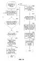
- the data service hubcan retrieve the recorded program and send it in its entirety to the SOI of the subscriber desiring to view the program.
- the data service hubcan retrieve and store the recorded program and play it back to the SOI of the subscriber desiring to view the program.
- Various other ways of retrieving and storing the desired program from an SOI different from the SOI of the subscriberare not beyond the scope and spirit of the present invention.
- an SOIcan include an interface that transmits S-Video formatted signals over a single electrical waveguide such as a coaxial cable.
- the interfacemay be desirable and helpful for home theater systems of subscribers that have inputs designed to receive S-Video formatted signals.
- an S-Video interface that is part of the SOI and a control interface that is coupled to a TVcan include a mixer, a local oscillator, a band pass filter, a diplexer, and one of an agile modulator (for the S-Video interface) and agile demodulator (for the control interface).
- the agile modulator and demodulatorscan be used when a single electrical waveguide drop is designed to feed an entire subscriber's premises.
- the S-Video formatted signalscan use the same electrical waveguide as regular formatted video signals.
- the agile modulators and demodulatorscan be eliminated.
- the SOIcan manage home or office events that often occur during video viewing by a subscriber.
- the SOI in combination with the remote controllercan manage events such as telephone calls, intercom calls, and door bell rings.
- the SOIcan be coupled to one or more cameras, door bells, intercoms, and other like devices.
- the SOIcan interrupt video viewing of a subscriber and inform the subscriber of home events.
- the SOIcan display video from the one or more cameras upon detecting an event that is being tracked by the cameras, such as doorbell ringing event.
- the SOIcan display messages on a subscriber's TV when a video camera event or door bell ring is detected or if a phone call is received at the subscriber's premises.
- the SOIcan display messages on the subscriber's remote controller when any of these events occur.
- the messagescan be displayed by both the TV and the remote controller.
- the remote controllercan be used in combination with the SOI to manage these home events.
- a subscribercould answer a phone call with his remote controller that can be equipped with a microphone and speaker (or phone jack inputs) while the SOI mutes or pauses a video program being viewed by the subscriber.
- the remote controller equipped with the microphone and speaker (or phone jack)could also be used to answer door calls if the subscriber's premises is equipped with an intercom system.
- the remote controllercould also be used to activate electric locks on the doors of the subscriber's premises.
- Other additional home events that can be managed by the SOIare not beyond the scope and spirit of the invention.
- the SOIcan include hardware such as a digital RF tuner and a digital demodulator.
- the digital tunercan be used to receive one of an array of digital channels that may be propagated across the network from a data service hub.
- the digital demodulatorcan convert received digital television programming into the analog domain.
- the SOIcan also include an agile RF modulator.
- the agile RF modulatorcan modulate television programming received from the digital demodulators on to analog RF channels that can be tuned with a conventional television.
- the SOImay also include one or more point of deployment (POD) modules for descrambling channels that are scrambled at the data service hub.
- the PODs of the SOIcan also include an out-of-band (OOB) processing submodule that can support communications between the SOI and the data service hub.
- OOBout-of-band
- the out-of-band processing submodulecan recover downstream control information originating from the data service hub.
- Each PODmay further include security modules such as a copy protection module and a conditional access module.
- the copy protection modulecan verify the POD module is plugged into an acceptable host, such as an SOI.
- the conditional access modulecan descramble signals and authorize reception of individual channels and programs for a particular SOI.
- Other exemplary hardware for the SOIcan include an MPEG decoder, diplexers, and a control interface transceiver for supporting communications between the control interface and the SOI.
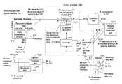
- FIG. 1is a functional block diagram of some core components of an exemplary optical network architecture according to an exemplary embodiment of the present invention that can include a subscriber optical interface coupled to a remote controller.
- FIG. 2is a functional block diagram illustrating additional aspects of an exemplary optical network architecture according to an exemplary embodiment of the present invention.
- FIG. 3is a functional block diagram illustrating an exemplary data service hub according to an exemplary embodiment of the present invention.
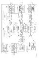
- FIG. 4is a functional block diagram illustrating an exemplary laser transceiver node according to an exemplary embodiment of the present invention.
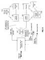
- FIG. 5is a functional block diagram illustrating an optical tap coupled to a subscriber optical interface according to an exemplary embodiment of the present invention.
- FIG. 6is a functional block diagram illustrating exemplary subscriber equipment that can be serviced by the subscriber optical interface according to an exemplary embodiment of the present invention.
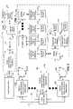
- FIG. 7is a functional block diagram illustrating a several exemplary components that may be contained in the subscriber optical interface according to one exemplary embodiment of the present invention.
- FIG. 8Ais a functional block diagram illustrating an infrared control interface and an infrared remote controller according to one exemplary embodiment of the present invention.
- FIG. 8Bis a frequency spectrum diagram illustrating responses of a diplexer that may be part of a control interface according to the exemplary embodiment illustrated in FIG. 8A .
- FIG. 8Cis a functional block diagram illustrating a diplexer that may be part of the control interface illustrated in FIG. 8A .
- FIG. 8Dis a circuit diagram illustrating exemplary components of the diplexer illustrated in FIG. 8C .
- FIG. 9Ais a functional block diagram illustrating an infrared control interface and an infrared remote controller according to another exemplary embodiment of the present invention.
- FIG. 9Bis a frequency spectrum diagram illustrating responses of a diplexer that may be part of a control interface according to the exemplary embodiment illustrated in FIG. 9A .
- FIG. 10Ais a functional block diagram illustrating an RF control interface and an RF remote controller according to a further exemplary embodiment of the present invention.
- FIG. 10Bis a circuit diagram illustrating exemplary components of the diplexer illustrated in FIG. 10A .
- FIG. 11is a functional block diagram illustrating a control interface, an RF remote controller, and an RF transceiver contained within a power supply housing according to a another exemplary embodiment of the present invention.
- FIG. 12is a logic flow diagram illustrating an exemplary method for tuning a television to an analog RF channel according to an exemplary embodiment of the present invention.
- FIG. 13is a logic flow diagram illustrating an exemplary method for tuning a television to a digital channel according to an exemplary embodiment of the present invention.
- FIG. 14is a logic flow diagram illustrating an exemplary method for tuning a television to an Internet Protocol formatted channel according to an exemplary embodiment of the present invention.
- FIG. 15is a logic flow diagram illustrating an exemplary method for tuning a television to an electronic program guide (EPG) according to an exemplary embodiment of the present invention.
- EPGelectronic program guide
- FIG. 16is a logic flow diagram illustrating an exemplary method for displaying an instant replay according to an exemplary embodiment of the present invention.
- FIG. 17is a logic flow diagram illustrating an exemplary method for displaying a recorded program according to an exemplary embodiment of the present invention.
- FIG. 18Ais a functional block diagram illustrating a how personal video recorders contained within subscriber optical interfaces may be networked according to a one exemplary embodiment of the present invention.
- FIG. 18Bis a logic flow diagram illustrating an exemplary method for locating a recorded program that may be stored on one or more personal video recorders according to an exemplary embodiment of the present invention.
- FIG. 19is a functional block diagram illustrating an S-Video interface according to a one exemplary embodiment of the present invention.
- FIG. 20Ais a functional block diagram illustrating an S-Video interface system comprising agile modulators positioned after diplexers and agile demodulators positioned before diplexers according to a one exemplary embodiment of the present invention.
- FIG. 20Bis a logic flow diagram illustrating an exemplary method for communicating S-Video over a single electrical wave guide according to the exemplary embodiment illustrated in FIG. 20A .
- FIG. 21Ais a functional block diagram illustrating an S-Video interface system comprising agile modulators positioned before diplexers and demodulators positioned after diplexers according to a one exemplary embodiment of the present invention.
- FIG. 21Bis a logic flow diagram illustrating an exemplary method for communicating S-Video over a single electrical wave guide according to the exemplary embodiment illustrated in FIG. 21A .
- FIG. 22Ais a functional block diagram illustrating additional components such as door bells, cameras, intercoms, and doors that can be controlled with the SOI according to one exemplary embodiment of the present invention.
- FIG. 22Bis a logic flow diagram illustrating an exemplary method for managing home or office events according to one exemplary embodiment of the present invention.
- FIG. 22Cis a functional block diagram illustrating a sub-method or routine for managing phone calls that corresponds to the method illustrated in FIG. 22B .
- FIG. 22Dis a logic flow diagram illustrating an exemplary sub-method or routine for managing door visitors that corresponds to the method illustrated in FIG. 22B .
- video signaling processing hardwarethat is present within the subscriber's premises for tuning video programs can be minimized or reduced without sacrificing a range of services available to a subscriber from a fiber-to-the-home optical network.
- the size and complexity of a set-top boxcan be reduced and in some cases, the set-top box can be eliminated. It is recognized that set-top boxes are frequently needed because most conventional television sets, at the time of this writing, cannot tune digital channels or Internet Protocol (IP) broadcasts.
- IPInternet Protocol
- Some components of the present inventionmay be physically located in a subscriber's premises but would have the main purpose of relaying information back to the subscriber optical interface that is physically located external to a subscriber's premises such as a house. In this way, a service provider can update or maintain more complex network equipment that is accessible on the outside of a subscriber's premises such as a single family home or office.
- FIG. 1is a functional block diagram illustrating an exemplary optical network architecture 100 according to the present invention.
- the exemplary optical network architecture 100comprises a data service hub 110 . Further details of the data service hub 110 will be discussed in detail below with respect to FIG. 3 .
- the data service hub 110is coupled to a plurality of outdoor laser transceiver nodes 120 .
- the laser transceiver nodes 120are each coupled to a plurality of optical taps 130 .
- the optical taps 130can be coupled to a plurality of subscriber optical interfaces 140 .
- Coupled to each subscriber optical interface 140can be a broadcast receiver 117 such as a television (TV) set, a remote control interface 108 , and a remote control 108 .
- a broadcast receiver 117such as a television (TV) set
- a remote control interface 108a remote control interface
- One focus of the present inventionis on the hardware and software used to support communications between the subscriber optical interface (SOI) 140 , the remote control interface 108 , and the remote control 103 .
- SOIsubscriber optical interface
- optical waveguides 150 , 160 , 170 , and 180are illustrated by arrows where the arrowheads of the arrows illustrate exemplary directions of data flow between respective components of the illustrative and exemplary optical network architecture 100 .
- FIG. 1While only an individual laser transceiver node 120 , an individual optical tap 130 , and an individual subscriber optical interface 140 are illustrated in FIG. 1 , as will become apparent from FIG. 2 and its corresponding description, a plurality of laser transceiver nodes 120 , optical taps 130 , and subscriber optical interfaces 140 can be employed without departing from the scope and spirit of the present invention. Typically, in many of the exemplary embodiments of the multiple service provider system of the present invention, several subscriber optical interfaces 140 can be coupled to one or more optical taps 130 .
- the outdoor laser transceiver node 120can allocate additional or reduced bandwidth based upon the demand of one or more subscribers that use the subscriber optical interfaces 140 .
- the outdoor laser transceiver node 120can be designed to withstand outdoor environmental conditions and can be designed to hang on a strand or fit in a pedestal or “hand hole (underground vault).”
- the outdoor laser transceiver nodecan operate in a temperature range between minus 40 degrees Celsius to plus 60 degrees Celsius.
- the laser transceiver node 120can operate in this temperature range by using passive cooling devices that do not consume power.
- the outdoor laser transceiver node 120does not require active cooling and heating devices that control the temperature surrounding the laser transceiver node 120 .
- the RF system of the present inventionattempts to place more of the decision-making electronics at the data service hub 110 instead of the laser transceiver node 120 .
- the decision-making electronicsare larger in size and produce more heat than the electronics placed in the laser transceiver node of the present invention.
- the laser transceiver node 120does not require active temperature controlling devices, the laser transceiver node 120 lends itself to a compact electronic packaging volume that is typically smaller than the environmental enclosures of conventional routers. Further details of the components that make up the laser transceiver node 120 will be discussed in further detail below with respect to FIG. 4 .
- three trunk optical waveguides 160 , 170 , and 180can propagate optical signals from the data service hub 110 to the outdoor laser transceiver node 120 .
- optical waveguideused in the present application can apply to optical fibers, planar light guide circuits, and fiber optic pigtails and other like optical waveguide components that are used to form an optical architecture.
- a first optical waveguide 160can carry downstream broadcast analog video and control signals.
- the analog signalscan be carried in a traditional cable television format wherein the broadcast signals are modulated onto analog optical carriers with an optical transmitter (not shown in this Figure) in the data service hub 110 .
- the first optical waveguide 160can also carry upstream RF signals that are generated by respective video Broadcast receivers 117 .
- a second optical waveguide 170can carry upstream and downstream targeted services such as data and telephone services to be delivered to or received from one or more subscriber optical interfaces 140 .
- the second optical waveguide 170can also propagate internet protocol broadcast packets, as is understood by those skilled in the art.
- a third optical waveguide 180can transport data signals upstream from the outdoor laser transceiver node 120 to the data service hub 110 .
- the optical signals propagated along the third optical waveguide 180can also comprise data and telephone services received from one or more subscribers. Similar to the second optical waveguide 170 , the third optical waveguide 180 can also carry IP broadcast packets, as is understood by those skilled in the art.
- the third or upstream optical waveguide 180is illustrated with dashed lines to indicate that it is merely an option or part of one exemplary embodiment according to the present invention. In other words, the third optical waveguide 180 can be removed.
- the second optical waveguide 170propagates optical signals in both the upstream and downstream directions as is illustrated by the double arrows depicting the second optical waveguide 170 .
- the second optical waveguide 170propagates bidirectional optical signals
- only two optical waveguides 160 , 170would be needed to support the optical signals propagating between the data server's hub 110 in the outdoor laser transceiver node 120 .
- a single optical waveguidecan be the only link between the data service hub 110 and the laser transceiver node 120 .
- three different wavelengthscan be used for the upstream and downstream signals.
- bi-directional datacould be modulated on one wavelength.
- the optical tap 130can comprise an 8-way optical splitter. This means that the optical tap 130 comprising an 8-way optical splitter can divide downstream optical signals eight ways to serve eight different subscriber optical interfaces 140 . In the upstream direction, the optical tap 130 can combine the optical signals received from the eight subscriber optical interfaces 140 .
- the optical tap 130can comprise a 4-way splitter to service four subscriber optical interfaces 140 .
- the optical tap 130can further comprise a 4-way splitter that is also a pass-through tap meaning that a portion of the optical signal received at the optical tap 130 can be extracted to serve the 4-way splitter contained therein while the remaining optical energy is propagated further downstream to another optical tap or another subscriber optical interface 140 .
- the present inventionis not limited to 4-way and 8-way optical splitters. Other optical taps having fewer or more than 4-way or 8-way splits are not beyond the scope of the present invention.
- the outdoor laser transceiver node 120 , the optical tap 130 , and the optical waveguide disposed between the laser transceiver node and the optical tap 130can form and can be referred to as a proximate optical network 135 that is close to subscribers.
- FIG. 2is a functional block diagram illustrating an exemplary optical network architecture 100 that further includes subscriber groupings 200 that correspond with a respective outdoor laser transceiver node 120 .
- FIG. 2illustrates the diversity of the exemplary optical network architecture 100 where a number of optical waveguides 150 coupled between the outdoor laser transceiver node 120 and the optical taps 130 is minimized.
- FIG. 2also illustrates the diversity of subscriber groupings 200 that can be achieved with the optical tap 130 .
- Each optical tap 130can comprise an optical splitter.
- the optical tap 130allows multiple subscriber optical interfaces 140 to be coupled to a single optical waveguide 150 that is coupled to the outdoor laser transceiver node 120 .
- six optical fibers 150are designed to be coupled to the outdoor laser transceiver node 120 .
- sixteen subscriberscan be assigned to each of the six optical fibers 150 that are coupled to the outdoor laser transceiver node 120 .
- twelve optical fibers 150can be coupled to the outdoor laser transceiver node 120 while eight subscriber optical interfaces 140 are assigned to each of the twelve optical fibers 150 .
- the number of subscriber optical interfaces 140 assigned to a particular waveguide 150 that is coupled between the outdoor laser transceiver node 120 and a subscriber optical interface 140can be varied or changed without departing from the scope and spirit of the present invention. Further, those skilled in the art recognize that the actual number of subscriber optical interfaces 140 assigned to the particular fiber optic cable is dependent upon the amount of power available on a particular optical fiber 150 .
- optical tap 130 Acan connect subscriber optical interfaces 140 A1 through subscriber optical interface 140 AN to the outdoor laser transmitter node 120
- optical tap 130 Acan also connect other optical taps 130 such as optical tap 130 AN to the laser transceiver node 120 .
- the combinations of optical taps 130 with other optical taps 130 in addition to combinations of optical taps 130 with subscriber optical interfaces 140are limitless.
- concentrations of distribution optical waveguides 150 at the laser transceiver node 120can be reduced. Additionally, the total amount of fiber needed to service a subscriber grouping 200 can also be reduced.
- the distance between the laser transceiver node 120 and the data service hub 110can comprise a range between 0 and 80 kilometers.
- the present inventionis not limited to this range. Those skilled in the art will appreciate that this range can be expanded by selecting various off-the-shelf components that make up several of the devices of the present system.
- optical waveguides disposed between the data service hub 110 and outdoor laser transceiver node 120are not beyond the scope of the present invention. Because of the bi-directional capability of optical waveguides, variations in the number and directional flow of the optical waveguides disposed between the data service hub 110 and the outdoor laser transceiver node 120 can be made without departing from the scope and spirit of the present invention.
- this functional block diagramillustrates an exemplary data service hub 110 of the present invention for an individual service provider. If an optical network supports another individual service provider within the data service hub 110 as illustrated in FIG. 3 , then all of the components illustrated in FIG. 3 would be replicated to support the other service provider. That is, each service provider would include its own modulators 310 , 315 , an internet router 340 , a telephone switch 345 , laser transceiver node routing device 355 , and optical transmitters 325 and receivers 370 .
- the service providerscan share much of the equipment illustrated in FIG. 3 . That is, equipment between the laser transceiver node routing device 355 and the ports 365 and including the laser transceiver node routing device 355 can have inputs for each service provider (not shown in FIG. 3 ).
- the exemplary data service hub 110 illustrated in FIG. 3is also designed for a two trunk optical waveguide system. That is, this data service hub 110 of FIG. 3 is designed to send and receive optical signals to and from the outdoor laser transceiver node 120 along the first optical waveguide 160 . With this exemplary embodiment, only the second optical waveguide 170 supports bi-directional data flow. In this way, the third optical waveguide 180 discussed above is not needed.
- the data service hub 110can comprise one or more modulators 310 , 315 that are designed to support television broadcast services.
- the one or more modulators 310 , 315can be analog or digital type modulators. In one exemplary embodiment, there can be at least 78 modulators present in the data service hub 110 .
- modulators 310 , 315can be varied without departing from the scope and spirit of the present invention.
- the signals from the modulators 310 , 315are combined in a first combiner 320 .
- the combined video services controller signals and broadcast video signalsare supplied to an optical transmitter 325 where these signals are converted into optical form.
- some portion of the video signalsmay be generated and converted to optical form at a remote first data service hub 110 .
- theymay be combined with other signals generated locally.
- the optical transmitter 325can comprise one of Fabry-Perot (F-P) laser, distributed feedback laser (DFB), or Vertical Cavity Surface Emitting Laser (VCSEL).
- F-PFabry-Perot
- DFBdistributed feedback laser
- VCSELVertical Cavity Surface Emitting Laser
- other types of optical transmittersare possible and are not beyond the scope of the present invention.
- the data service hub 110lends itself to efficient upgrading by using off-the-shelf hardware to generate optical signals.
- the optical signals generated by the optical transmitter 325are propagated to amplifier 330 such as an Erbium Doped Fiber Amplifier (EDFA) where the optical signals are amplified.
- EDFAErbium Doped Fiber Amplifier
- the amplified optical signalsare then propagated out of the data service hub 110 via a video signal input/output port 335 which is coupled to one or more first optical waveguides 160 .
- the data service hub 110 illustrated in FIG. 3can further comprise an Internet router 340 .
- the data service hub 110can further comprise a telephone switch 345 that supports telephony service to the subscribers of the optical network system 100 .
- other telephony servicesuch as Internet Protocol telephony can be supported by the data service hub 110 .
- the telephone switch 345could be eliminated in favor of lower cost VoIP equipment.
- the telephone switch 345could be substituted with other telephone interface devices such as a soft switch and gateway. But if the telephone switch 345 is needed, it may be located remotely from the data service hub 110 and can be coupled through any of several conventional methods of interconnection.
- the data service hub 110can further comprise a logic interface 350 that is coupled to a laser transceiver node routing device 355 .
- the logic interface 350can comprise a Voice over Internet Protocol (VOIP) gateway when required to support such a service.
- the laser transceiver node routing device 355can comprise a conventional router that supports an interface protocol for communicating with one or more laser transceiver nodes 120 .
- This interface protocolcan comprise one of gigabit or faster Ethernet, Internet Protocol (IP) or SONET protocols.
- IPInternet Protocol
- the logic interface 350 and laser transceiver node routing device 355can read packet headers originating from the laser transceiver nodes 120 and the internet router 340 .
- the logic interface 350can also translate interfaces with the telephone switch 345 . After reading the packet headers, the logic interface 350 and laser transceiver node routing device 355 can determine where to send the packets of information.
- the laser transceiver node routing device 355can also supply downstream data signals to respective optical transmitters 325 .
- the data signals converted by the optical transmitters 325can then be propagated to a bi-directional splitter 360 .
- the optical signals sent from the optical transmitter 325 into the bi-directional splitter 360can then be propagated towards a bi-directional data input/output port 365 that is coupled to a second optical waveguide 170 that supports bi-directional optical data signals between the data service hub 110 and a respective laser transceiver node 120 .
- Upstream optical signals received from a respective laser transceiver node 120can be fed into the bi-directional data input/output port 365 where the optical signals are then forwarded to the bi-directional splitter 360 .
- respective optical receivers 370can convert the upstream optical signals into the electrical domain.
- the upstream electrical signals generated by respective optical receivers 370are then fed into the laser transceiver node routing device 355 .
- each optical receiver 370can comprise one or more photoreceptors or photodiodes that convert optical signals into electrical signals.
- the optical transmitters 325can propagate optical signals at 1310 nm. But where distances between the data service hub 110 and the laser transceiver node are more extreme, the optical transmitters 325 can propagate the optical signals at wavelengths of 1550 nm with or without appropriate amplification devices.
- most of the data servicesare transported by a digital optical carrier having a wavelength of 1310 nm.
- the broadcast servicesare transported by analog optical carriers in the 1550 nm wavelength region.
- An optical diplexer 515(discussed below and illustrated in FIG. 5 ) will separate the digital optical carrier from the one or more analog optical carriers according to the carriers respective wavelength.
- optical transmitters 325 for each circuitmay be optimized for the optical path lengths needed between the data service hub 110 and the outdoor laser transceiver node 120 .
- the wavelengths discussedare practical but are only illustrative in nature. In some scenarios, it may be possible to use communication windows at 1310 and 1550 nm in different ways without departing from the scope and spirit of the present invention. Further, the present invention is not limited to a 1310 and 1550 nm wavelength regions. Those skilled in the art will appreciate that smaller or larger wavelengths for the optical signals are not beyond the scope and spirit of the present invention.
- the laser transceiver node 120can comprise an optical signal input port 405 that can receive optical signals propagated from the data service hub 110 that are propagated along a first optical waveguide 160 .
- the optical signals received at the optical signal input port 405can comprise downstream broadcast video data.
- the downstream broadcast video datacan also comprise downstream video service control signals.
- the downstream broadcast video datais typically modulated on an analog optical carrier.
- the downstream optical signals received at the input port 405are propagated through an amplifier 410 such as an Erbium Doped Fiber Amplifier (EDFA) in which the optical signals are amplified.
- EDFAErbium Doped Fiber Amplifier
- the amplified optical signalsare then propagated to an optical splitter 415 that divides the downstream broadcast video optical signals (that may also include video service control signals if sent on modulated carriers) among diplexers 420 that are designed to forward optical signals to predetermined subscriber groups 200 .
- EDFAErbium Doped Fiber Amplifier
- the laser transceiver node 120can further comprise a bi-directional optical signal input/output port 425 that connects the laser transceiver node 120 to a second optical waveguide 170 that supports bi-directional data flow between the data service hub 110 and laser transceiver node 120 .
- Downstream optical signalsflow through the bi-directional optical signal input/output port 425 to an optical waveguide transceiver 430 that converts downstream optical signals into the electrical domain.
- the optical waveguide transceiver 430further converts upstream electrical signals into the optical domain.
- the optical waveguide transceiver 430can comprise an optical/electrical converter and an electrical/optical converter. Downstream and upstream electrical signals are communicated between the optical waveguide transceiver 430 and an optical tap routing device 435 .
- the optical tap routing device 435can manage the interface with the data service hub optical signals and can route or divide or apportion the data service hub signals according to individual tap multiplexers 440 that communicate optical signals with one or more optical taps 130 and ultimately one or more subscriber optical interfaces 140 . It is noted that tap multiplexers 440 operate in the electrical domain to modulate laser transmitters in order to generate optical signals that are assigned to groups of subscribers coupled to one or more optical taps.
- Optical tap routing device 435is notified of available upstream data packets and upstream RF packets as they arrive, by each tap multiplexer 440 .
- the optical tap routing deviceis coupled to each tap multiplexer 440 to receive these upstream data and RF packets.
- the optical tap routing device 435can relay upstream video control return packets and information packets that can comprise data and/or telephony packets to the data service hub 110 via the optical waveguide transceiver 430 and bidirectional optical signal input/output 425 .
- the optical tap routing device 435can build a lookup table from these upstream data packets coming to it from all tap multiplexers 440 (or ports), by reading the source IP address of each packet, and associating it with the tap multiplexer 440 through which it came.
- the aforementioned lookup tablecan be used to route packets in the downstream path. As each downstream data packet comes in from the optical waveguide transceiver 430 , the optical tap routing device looks at the destination IP address (which is the same as the source IP address for the upstream packets). From the lookup table the optical tap routing device 435 can determine which port (or, tap multiplexer 440 ) is coupled to that IP address, so it sends the packet to that port. This can be described as a normal layer 3 router function as is understood by those skilled in the art.
- the optical tap routing device 435can assign multiple subscribers to a single port. More specifically, the optical tap routing device 435 can service groups of subscribers with corresponding respective, single ports.
- the optical taps 130 coupled to respective tap multiplexers 440can supply downstream optical signals to pre-assigned groups of subscribers who receive the downstream optical signals with the subscriber optical interfaces 140 .
- the optical tap routing device 435can determine which tap multiplexers 440 is to receive a downstream electrical signal, or identify which tap multiplexer 440 propagated an upstream optical signal (that is received as an electrical signal).
- the optical tap routing device 435can format data and implement the protocol required to send and receive data from each individual subscriber coupled to a respective optical tap 130 .
- the optical tap routing device 435can comprise a computer or a hardwired apparatus that executes a program defining a protocol for communications with groups of subscribers assigned to individual ports.
- the single ports of the optical tap routing device 435are coupled to respective tap multiplexers 440 .
- the laser transceiver node 120can adjust a subscriber's bandwidth on a subscription basis or on an as-needed or demand basis.
- the laser transceiver node 120 via the optical tap routing device 435can offer data bandwidth to subscribers in pre-assigned increments.
- the laser transceiver node 120 via the optical tap routing device 435can offer a particular subscriber or groups of subscribers bandwidth in units of 1, 2, 5, 10, 20, 50, 100, 200, and 450 Megabits per second (Mb/s).
- Mb/sMegabits per second
- Each tap multiplexer 440propagate optical signals to and from various groupings of subscribers by way of laser optical transmitter 525 and laser optical receiver 370 .
- Each tap multiplexer 440is coupled to a respective optical transmitter 325 .
- each optical transmitter 325can comprise one of a Fabry-Perot (F-P) laser, a distributed feedback laser (DFB), or a Vertical Cavity Surface Emitting Laser (VCSEL).
- F-PFabry-Perot
- DFBdistributed feedback laser
- VCSELVertical Cavity Surface Emitting Laser
- the optical transmittersproduce the downstream optical signals that are propagated towards the subscriber optical interfaces 140 .
- Each tap multiplexer 440is also coupled to an optical receiver 370 .
- Each optical receiver 370can comprise photoreceptors or photodiodes. Since the optical transmitters 325 and optical receivers 370 can comprise off-the-shelf hardware to generate and receive respective optical signals, the laser transceiver node 120 lends itself to efficient upgrading and maintenance to provide significantly increased data rates.
- Each optical transmitter 325 and each optical receiver 370are coupled to a respective bi-directional splitter 360 .
- Each bi-directional splitter 360in turn is coupled to a diplexer 420 which combines the optical signals received from the splitter 415 with the downstream optical signals received from respective optical receivers 370 .
- broadcast video services as well as data servicescan be supplied with a single optical waveguide such as a distribution optical waveguide 150 as illustrated in FIG. 2 .
- optical signalscan be coupled from each respective diplexer 420 to a combined signal input/output port 445 that is coupled to a respective distribution optical waveguide 150 .
- the laser transceiver node 120does not employ a conventional router.
- the components of the laser transceiver node 120can be disposed within a compact electronic packaging volume.
- the laser transceiver node 120can be designed to hang on a strand or fit in a pedestal similar to conventional cable TV equipment that is placed within the “last,” mile or subscriber proximate portions of a network. It is noted that the term, “last mile,” is a generic term often used to describe the last portion of an optical network that connects to subscribers.
- optical tap routing device 435is not a conventional router, it does not require active temperature controlling devices to maintain the operating environment at a specific temperature. Optical tap routing device 435 does not need active temperature controlling devices because it can be designed with all temperature-rated components. In other words, the laser transceiver node 120 can operate in a temperature range between minus 40 degrees Celsius to 60 degrees Celsius in one exemplary embodiment.
- the laser transceiver node 120does not comprise active temperature controlling devices that consume power to maintain temperature of the laser transceiver node 120 at a single temperature
- the laser transceiver node 120can comprise one or more passive temperature controlling devices 450 that do not consume power.
- the passive temperature controlling devices 450can comprise one or more heat sinks or heat pipes that remove heat from the laser transceiver node 120 .
- the present inventionis not limited to these exemplary passive temperature controlling devices.
- the laser transceiver node 120can also provide high speed symmetrical data transmissions. In other words, the laser transceiver node 120 can propagate the same bit rates downstream and upstream to and from a network subscriber. This is yet another advantage over conventional networks, which typically cannot support symmetrical data transmissions as discussed in the background section above. Further, the laser transceiver node 120 can also serve a large number of subscribers while reducing the number of connections at both the data service hub 110 and the laser transceiver node 120 itself.
- the laser transceiver node 120also lends itself to efficient upgrading that can be performed entirely on the network side or data service hub 110 side. That is, upgrades to the hardware forming the laser transceiver node 120 can take place in locations between and within the data service hub 110 and the laser transceiver node 120 . This means that the subscriber side of the network (from distribution optical waveguides 150 to the subscriber optical interfaces 140 ) can be left entirely intact during an upgrade to the laser transceiver node 120 or data service hub 110 or both.
- the data communications path between the laser transceiver node 120 and the data service hub 110can operate at 1 Gb/s.
- the data path to subscriberscan support up to 2.7 Gb/s
- the data path to the networkcan only support 1 Gb/s. This means that not all of the subscriber bandwidth is useable. This is not normally a problem due to the statistical nature of bandwidth usage.
- An upgradecould be to increase the 1 Gb/s data path speed between the laser transceiver node 120 and the data service hub 110 . This may be done by adding more 1 Gb/s data paths. Adding one more path would increase the data rate to 2 Gb/s, approaching the total subscriber-side data rate. A third data path would allow the network-side data rate to exceed the subscriber-side data rate. In other exemplary embodiments, the data rate on one link could rise from 1 Gb/s to 2 Gb/s then to 10 Gb/s, so when this happens, a link can be upgraded without adding more optical links.
- the additional data pathsmay be achieved by any of the methods known to those skilled in the art. It may be accomplished by using a plurality of optical waveguide transceivers 430 operating over a plurality of optical waveguides, or they can operate over one optical waveguide at a plurality of wavelengths, or it may be that higher speed optical waveguide transceivers 430 could be used as shown above.
- a system upgradeis effected without having to make changes at the subscribers' premises.
- FIG. 5this Figure is a functional block diagram illustrating an optical tap 130 coupled to a subscriber optical interface 140 by a single optical waveguide 150 according to one exemplary embodiment of the present invention.
- the optical tap 130can comprise a combined signal input/output port 505 that is coupled to another distribution optical waveguide that is coupled to a laser transceiver node 120 .
- the optical tap 130can comprise an optical splitter 510 that can be a 4-way or 8-way optical splitter. Other optical taps having fewer or more than 4-way or 8-way splits are not beyond the scope of the present invention.
- the optical tapcan divide downstream optical signals to serve respective subscriber optical interfaces 140 .
- the optical tap 130comprises a 4-way optical tap
- such an optical tapcan be of the pass-through type, meaning that a portion of the downstream optical signals is extracted or divided to serve a 4-way splitter contained therein, while the rest of the optical energy is passed further downstream to other distribution optical waveguides 150 .
- the optical tap 130is an efficient coupler that can communicate optical signals between the laser transceiver node 120 and a respective subscriber optical interface 140 .
- Optical taps 130can be cascaded, or they can be coupled in a star architecture from the laser transceiver node 120 . As discussed above, the optical tap 130 can also route signals to other optical taps that are downstream relative to a respective optical tap 130 .
- the optical tap 130can also connect to a limited or small number of optical waveguides so that high concentrations of optical waveguides are not present at any particular laser transceiver node 120 .
- the optical tapcan connect to a limited number of optical waveguides 150 at a point remote from the laser transceiver node 120 so that high concentrations of optical waveguides 150 at a laser transceiver node can be avoided.
- the optical tap 130can be incorporated within the laser transceiver node 120 .
- the subscriber optical interface 140functions to convert downstream optical signals received from the optical tap 130 into the electrical domain that can be processed with appropriate communication devices.
- the subscriber optical interface illustrated in FIG. 5is a basic unit. Further details of a preferred unit will be described below with respect to FIG. 7 .
- the subscriber optical interface 140functions to convert upstream electrical signals into upstream optical signals that can be propagated along a distribution optical waveguide 150 to the optical tap 130 .
- the subscriber optical interface 140can comprise an optical diplexer 515 that divides the downstream optical signals received from the distribution optical waveguide 150 between a bi-directional optical signal splitter 520 and an analog optical receiver 525 .
- the optical diplexer 515can separate or divide downstream optical signals based on wavelength. Typically, digital optical carriers will be propagated at a first wavelength while analog optical carriers will be propagated at second and third wavelengths different from the first wavelength.
- the optical diplexer 515can receive upstream optical signals generated by a digital optical transmitter 530 .
- the digital optical transmitter 530converts electrical binary/digital signals to optical form so that the optical signals can be transmitted back to the data service hub 110 .
- the digital optical receiver 540converts optical signals into electrical binary/digital signals so that the electrical signals can be handled by processor 550 .
- the analog optical receiver 525can convert the downstream, analog broadcast optical video signals into modulated RF television signals that are propagated out of the modulated RF signal output 535 .
- the modulated RF signal output 535can feed Broadcast receivers 117 such as video service terminals like television sets and radios.
- the analog optical receiver 525could process analog modulated RF transmission as well as digitally modulated RF transmissions for digital TV applications.
- the bi-directional optical signal splitter 520can propagate combined optical signals in their respective directions. That is, downstream optical signals entering the bi-directional optical splitter 520 from the optical diplexer 515 , are propagated to the digital optical receiver 540 . Upstream optical signals entering the splitter 520 from the digital optical transmitter 530 are sent to optical diplexer 515 and then to optical tap 130 .
- the bi-directional optical signal splitter 520is coupled to a digital optical receiver 540 that converts downstream data optical signals into the electrical domain. Meanwhile the bi-directional optical signal splitter 520 is also coupled to a digital optical transmitter 530 that converts upstream electrical signals into the optical domain.
- the digital optical receiver 540can comprise one or more photoreceptors or photodiodes that convert optical signals into the electrical domain.
- the digital optical transmittercan comprise one or more lasers such as the Fabry-Perot (F-P) Lasers, distributed feedback lasers, and Vertical Cavity Surface Emitting Lasers (VCSELs).
- F-PFabry-Perot
- VCSELsVertical Cavity Surface Emitting Lasers
- the digital optical receiver 540 and digital optical transmitter 530are coupled to a processor 550 that selects data intended for the instant subscriber optical interface 140 based upon an embedded address.
- the data handled by the processor 550can comprise one or more of telephony and data services such as an Internet service.
- the processor 550is coupled to a telephone input/output 555 that can comprise an analog interface.
- the processor 550is also coupled to a data interface 560 that can provide a link to computer devices, set top boxes, ISDN phones, and other like devices.
- the data interface 560can comprise an interface to a Voice over Internet Protocol (VoIP) telephone or Ethernet telephone.
- VoIPVoice over Internet Protocol
- the data interface 560can comprise one of Ethernet's (10BaseT, 100BaseT, Gigabit) interface, HPNA interface, a universal serial bus (USB) an IEEE1394 interface, an ADSL interface, and other like interfaces.
- FIG. 6this Figure is a functional block diagram illustrating exemplary subscriber equipment that can be serviced by the subscriber optical interface 140 according to an exemplary embodiment of the present invention.
- the subscriber optical interface 140may service data equipment such as computers 562 and telephones 564 .
- the subscriber optical interface 104can support digital video interfaces 619 that relay signals between the SOI 140 and a TV.
- the output from the modulated RF signal output 535may be split among a plurality of TV sets 117 and other devices such as recorders 119 that can include personal video recorders or video cassette recorders and other like equipment.
- An electrical splitter 605can be used to split or divide the RF signals, and to combine return control signals as described below.
- the signals propagating along the electrical waveguidemay comprise analog-modulated RF carriers that may be tuned directly by a TV 117 .
- control interfaces 108 between the Subscriber Optical Interface 140 and the TVmay be used. Their operation will be described in greater detail below.
- a remote control handheld unit 103can be used.
- the remote control 103may communicate with the TV 117 using the TV's remote control receiver (usually but not necessarily, the remote control operates using infrared—IR—signals. Other signaling, such as RF or ultrasonic, may be used and is not beyond the scope and spirit of the present invention).
- the remote control handheld unit 103is designed to communicate with the Subscriber Optical Interface 140 , and may do so via a control interface 108 connected to the RF cable 610 from the Subscriber Optical Interface 140 to the TV 117 .
- a control interface 108is not used.
- remote control hand-held unit 103that controls the TV 117 can control the recorder 119 and other consumer electronics devices. This detailed description will primarily discuss controlling the TV, but it is understood that other devices may also be controlled by the same remote control hand-held unit 103 .
- this Figureis a functional block diagram illustrating a several additional exemplary components that may be contained in the subscriber optical interface 140 according to one preferred and exemplary embodiment of the present invention.
- the modulated RF signalsmay be split along several paths of which three are shown by way of example but not limitation. The splitting is performed in an electrical RF splitter 605 that can split or divide the RF signals.
- the top direct path 702is for signals that are to be tuned directly by the TV set 117 . As of this writing, these signals are standard analog-modulated TV signals according to the NTSC standard in North America, and according to either the PAL or SECAM standards in other countries. These standards are well known to those skilled in the art.
- These signalsare supplied directly to the TV set(s) 117 by way of diplexers 720 A and 720 B.
- the functionality of these two diplexers 720 A, 720 Bwill be described below, where a plurality of embodiments will be shown.
- the signalsare output to the TV set(s) 117 through the Modulated Signal Output 535 .
- STTset top terminal
- the second signal pathis supplied to an RF tuner 704 A, which converts the modulated RF signal to baseband for further processing.
- the tuner 704 Amay be used for either analog-modulated or digital-modulated RF signals as is understood by those skilled in the art.
- Analog-modulated signalsare demodulated in analog demodulator 310 A. The main reason why an analog signal may be modulated at this point is if it is to be displayed on a TV 117 that is not capable of tuning the channel in question. Another reason would be if it is desired to display the channel on a display, such as a home theater, that is connected via a digital interface and does not have an RF tuner associated with it.
- the demodulated analog signal from analog demodulator 310 Ais supplied to a VBI decoder 710 , which is used to recover VBI data such as closed captioning information, well known to those skilled in the art. This data is used primarily to add captioning for hearing impaired viewers.
- the VBI decoder 710recovers the VBI data and supplies it to a multimedia processor 714 A that can add the closed captioning information to the programming signal.
- the multimedia processor 714 Ais also capable of adding text and graphics to the video signal, among other tasks. It is also connected to processor 550 , and can be used to supply messages to viewers in the form of on-screen text and graphics as will be described below.
- the signalis supplied to an agile RF modulator 718 A, another component well known to those skilled in the art. It modulates the video and audio signals onto an RF carrier for transmission to the TV set 117 .
- the signal from RF tuner 704 Amay also go to digital demodulator 706 A, which is used in place of analog demodulator 310 A if the tuned signal is digitally modulated. From the digital demodulator 706 A, the signal may be supplied to a POD 708 A, or Point of Deployment module 708 A. This module 708 A can descramble a signal if it is transmitted scrambled over the fiber optic plant.
- POD 708 APoint of Deployment module 708 A.
- the inner functionality of the POD module 708 Ais shown for POD module 708 B, and will be explained below.
- a POD moduleis also known commercially as a CableCard.
- the descrambled digital signal from POD module 708 Acan be passed to an MPEG decoder 712 A that can recover an analog picture from the digital signal. Alternatively, it can output an MPEG-decoded digital signal ready to have any overlay information added in the multimedia processor 714 A and passed through to a digital display output such as the DVI interface (HDCP) 740 . As another option, the video signal can be outputted to an S-video interface 738 . Further details of the S-Video interface will be described below with respect to FIG. 19 . Finally, the MPEG decoder 712 A may do nothing except to pass through the MPEG encoded signal, if that signal is to be delivered on an interface designed to accommodate MPEG signals to the display device. Such an output is the DTCP 742 and 1394 interface. These output types are understood by those skilled in the art, and will be explained more fully below.
- Cable Television Laboratorieshas specified standard interfaces between a host device, which the Subscriber Optical Interface 140 is acting as in this case, and a display device such as a TV.
- the OpenCableTM Host Device core Functional Requirements documentOC-SP-HOST-CFR-I11-021126, calls for analog and two (including HDTV) types of digital video connections.
- the first digital interfaceis the DVI interface 740 , specified as applying only for a high definition display.
- the high definition displayrequires the compressed MPEG signal to be decompressed and converted to video components by the host device, in this case, the Subscriber Optical Interface 140 .
- This requirementincludes the requirement to verify the display device to show that it is permitted to display the output, and then to encrypt the display data so that it cannot be supplied to any other devices.
- This specificationrequires that the multimedia processor 714 to add any graphic elements to the video.
- the interfaceis called the DVI interface, and the verification and encryption is called HDCP.
- the other digital video interfaceis called 1394, after the IEEE specification used for communications.
- the corresponding verification and encryption systemis known as DTCP 742.
- This interface 1394is transmitted in MPEG compressed format, relying on the using device, such as a TV or VCR, to decompress the video.
- This specificationalso allows for transmission of a separate graphic to overlay the video, relying on the TV to merge the overlay with the picture.
- MPEG decoder 712 A and multimedia processor 714 Aare not needed for output material intended for output on the 1394/DTCP output 742, but they are required for material intended for output on the DVI/HDCP output 740 . They also would be required for output on any analog outputs, such as that going to an agile RF modulator 718 A. (Other analog outputs such as composite and YPrPb are not shown, but are within the scope of the invention. They are well known to those skilled in the art.)
- the output going to the multiplexing and format conditioning 746is video and audio display data that is to be delivered over a data path, such as data interface 560 . This is possible and is within the scope of the instant invention, but as of this writing, there are no industry standards for doing so.
- a second RF tuner 704 Bis illustrated and is intended to allow the Subscriber Optical Interface 140 to serve two or more TVs simultaneously, one being served via tuner 704 A and one being served by tuner 704 B. Yet another one or more TVs can be served directly via the direct path 702 . Furthermore, more than two RF tuners 704 may be used. It is possible to provide some tuners 704 built into the Subscriber Optical Interface 140 , and to provide provisions for additional tuners 704 and associated components to be plugged in for those subscribers demanding more service.
- the second tuner 704 Bis connected to a second digital demodulator 706 B. It could also be connected to another analog demodulator 310 A. However, in most instances, few analog signals would be handled on other than the direct path 702 , so it is generally not necessary to provide for a lot of analog demodulators 310 A.
- the output of digital demodulator 706 Bis supplied to a second POD module 708 B.
- This second module 708 Bis identical to POD module 708 A described above.
- the POD module 708 Bis defined in the specifications OpenCableTM POD Copy Protection System, OC-SP-PODCP-IF-I08-021126 and OpenCableTM Host-POD Interface Specification, OC-SP-HOSTPOD-IF-I11-021126, well known to those skilled in the art.
- the purpose of the POD modules 708is to provide for communications between the Subscriber Optical Interface 140 and control systems located at the data service hub 110 . It also provides descrambling of the incoming digital modulated signal when it is scrambled, and handles copy protection for the descrambled MPEG signal it passes to the remainder of the Subscriber Optical Interface 140 .
- the POD module 708 Bcomprises an out-of-band (OOB) processing submodule 728 that handles communications between the data service hub 110 and the Subscriber Optical Interface 140 . This is done via the OOB channel 730 .
- the OOB channel 730comprises QPSK tuner 732 and QPSK demodulator 734 . These components recover downstream control information transmitted according to one of two SCTE specifications, SCTE-167 or SCTE 178. These specifications are well known to those skilled in the art, and prescribe ways to transmit control data to set top terminals, STTs. The same control channel can transmit control data to the Subscriber Optical Interface 140 in the instant invention.
- the two SCTE specificationsalso prescribe upstream communications paths that are not practical in FTTH systems such as the instant system. Rather, upstream communications may be effected or achieved by putting the upstream data in packets and sending them back to the data service hub 110 on the normal data path.
- the data packetsare converted to RF signals for delivery to the control system.
- a similar technologyis taught in the commonly-owned application, entitled, “Method and System for Providing a Return Path for Signals Generated by Legacy Terminals in an Optical Network,” Non-provisional patent application Ser. No. 10/041,299.
- the return data path 752 from the OOB processing module 728 to processor 550is utilized. There is no need in the instant invention to actually generate the RF signal at the Subscriber Optical Interface 140 .
- the POD modulecomprises a conditional access module 726 , which handles authorization of reception of individual channels and programs, including descrambling the signal transmitted over the fiber.
- the second POD module 708 Balso comprises copy protection module 724 A, which verifies that the POD module 708 B is plugged into an acceptable host (in this case the Subscriber Optical Interface 140 ), and which encrypts the video at its output to prevent unauthorized detection of the output. All of this is described in the document, OpenCableTM HOST-POD Interface Specification, cited above.
- Operation of the signal flow from second POD module 708 Bis identical to that described above for the first POD module 708 A. Additional signal chains may be added as desired.
- IPTVInternet protocol television
- FIG. 7shows the IP video and audio packets coming through processor 550 and to IPTV-MPEG TS (transmit stream) converter 736 .
- This converter 736makes the IPTV packets look the same as packets transmitted via the RF modulated path described above.
- Switch S 2selects the input to the POD module 708 B, which input may either be from digital demodulator 706 B or from the processor 550 . Again, more than one POD module 708 may be connected to receive inputs from either source.
- Data being delivered to the subscriber via data interface 560comes through processor 550 as described above in FIG. 5 . It is possible to deliver video to the home via the data interface 560 , and this is accommodated via router 748 , which combines data from processor 550 with video and audio data from multiplexing and format conditioning block 746 . This conditioning block 746 can be used to make sure the video and audio data is in the proper format, and is routed to the proper device inside the home. Remote control information may be transmitted via data interface 560 , or it may be transmitted via the transmission methods taught below.
- Switch Sdxis a service disconnect switch that can be used to deny basic analog programming to the subscriber if he has not ordered it, or if he has not paid his bill.
- Switch Sdxis actuated by processor 550 in response to signals sent from the data service hub 110 . It may also be used to enforce a start-up mode in the case where a new subscriber moves to a dwelling which features this Subscriber Optical Interface 140 . For example, it may be that a new subdivision has put Subscriber Optical Interfaces 140 at every house. When the subscriber moves in, he can only receive one channel on his TV because switch Sdx is open, and because no signals are being processed in the Subscriber Optical Interface 140 .
- processor 550may be programmed to work such that when the subscriber turns on his TV and uses his remote control hand-held unit 103 , all he receives are instructions on his TV to put in his credit card information, which he does by pressing the appropriate buttons on his remote control hand-held unit 103 .
- the subscribercan also be presented a menu of services from which he can select those he wishes to purchase.
- the informationis relayed from processor 550 to the data service hub 110 , where the subscriber is authorized to receive service.
- the data service hub 110then notifies the processor 550 of the acceptance of the subscriber's credit card and service request.
- Processor 550can then turn on switch Sdx to allow analog TV broadcasts and can permit such other requested services as the subscriber has ordered.
- Coupled signals between the Subscriber Optical Interface 140 and the subscriber's TV set(s) 117will now be described. These teachings involve various configurations for diplexer 720 A which controls the TV channels transmitted via direct path 702 and the RF modulators 718 . The teachings also involve diplexer 720 B, which determines frequencies used for all TV channels and those used for control signals to and from control interface transceiver 722 . Those skilled in the art understand that diplexers 720 may comprise diplex filters are used to separate different frequency bands of signals, routing them in different directions. The diplex filter 720 also provides filtering, or removal, of incoming signals at frequencies that are not intended to pass through the diplex filter 720 .
- an RF agile modulator 718When an RF agile modulator 718 is used to deliver signals to the home, it is important to provide for stereo audio modulation. This may be done by building in a low cost DSP-based stereo encoder, which is known to those skilled in the art.
- the encoderis not needed so long as the original signal comes from an analog source and if the audio is not demodulated below the sum, difference and pilot carrier level.
- the audio signalmay be handled at its intercarrier frequency, 4.5 MHz in North America.
- the stereo-encoded signalis not normally available and must be generated in the modulator 718 .
- the processmay be simplified somewhat by pre-encoding in the data service hub 110 , and transmitting the pre-encoded components.
- These pre-encoded componentinclude the sum signal and the compounded difference signal. This technique is known to those skilled in the art.
- FIG. 8Athis Figure is a functional block diagram illustrating an infrared control interface 108 A and an infrared remote control 103 A according to one exemplary embodiment of the present invention.
- the control interface 108 Amay comprise an IR transmitter 806 , and IR receiver 808 , a controller 804 , an IR repeater transceiver 802 , and a diplexer 720 C.
- the remote control handheld unit 103can comprise a modification of a conventional remote control handheld unit. As with common remote controls, it transmits a signal to the TV 117 , usually using infrared (IR) transmission 813 C. Other forms of transmission are possible and known to those skilled in the art. These include supersonic sound and RF signals. Other wireless mediums and wire-based systems are not beyond the scope and spirit of the present invention.
- the remote control 103transmits channel tuning and volume control commands to the TV, in addition to other commands as provided for by the TV manufacturer. In the instant invention, the remote control handheld unit 103 also transmits signals to, and receives signals from, the control interface 108 . These signals may be transmitted using the same transmission technique used to transmit to the TV. As shown in FIG. 8A , IR transmissions 813 B to the control interface 108 are received on IR receiver 808 .
- Transmission 813 B to the handheld unit 103are transmitted by IR transmitter 806 .
- Both IR transmitter 806 and IR receiver 808are connected to controller 804 .
- the function of the controller 804 and IR repeater transceiver 802is to modulate the IR commands onto an RF carrier at the frequency used for remote control communications, 10.7 MHz in the exemplary embodiment. It also receives communications from the control interface transceiver 802 on the same frequency, and sends them as IR signals to the remote control 103 , by way of IR transmitter 816 .
- controller 804must switch communications between the two directions, and it must arbitrate occasional collisions as described below. All of these functions are understood by those skilled in the art.
- this Figureis a frequency spectrum diagram illustrating responses of the diplexer 720 C that may be part of a control interface 108 A according to the exemplary embodiment illustrated in FIG. 8A .
- the frequency spectrum diagramshows that frequencies below a certain frequency are transmitted through diplexer 720 C. These signals are called “video transmitted through” 810 , and propagate through direct path 702 of FIG. 7 . These signals may be tuned by the TV 117 .
- Video inserted at the Subscriber Optical Interface 140occupies the high side of diplexer 720 C, shown as 814 .
- video insertsmay be any program that is processed through RF tuners 704 of FIG. 7 or which comes through the IPTV path through IPTV to MPEG TS converter 736 .
- FIG. 8Balso illustrates the use of frequencies toward the high end of the UHF band for transmission of signals from the Subscriber Optical Interface 140 to the TV(s) 117 .
- All TVs 117 sold in North Americaare usually required to tune up to at least Channel 69 off-air (800-806 MHz).
- each TV 117may be expected to be able to tune to signals transmitted from agile RF modulators 718 , so long as the frequency of the modulator 718 doesn't exceed this channel.
- Those skilled in the artknow that it is common practice in cable TV networks to transmit analog modulated TV programs, in which all TVs can tune without STTs or any other equipment, at frequencies up to about 550 MHz.
- Cable TV systemsusually transmit digital modulated channels, which will require the Subscriber Optical Interface 140 to convert to analog signals. Since the digital signals above 550 MHz cannot be consumed directly by the subscriber's TVs 117 , it is possible to filter or remove those signals, and to use the frequency band between 550 MHz and channel 69 off-air, to insert signals generated by agile RF modulators 718 .
- this Figureis a functional block diagram illustrating a diplexer 720 C that may be part of the control interface 108 A illustrated in FIG. 8A .
- This diplex filter 720 Coperates in conjunction with diplex filter 720 B in the Subscriber Optical Interface 140 (See FIG. 7 ), to couple remote control signals to the control interface transceiver 722 , and from there to the processor 550 (and to couple control signals in the opposite direction, as described below).
- the diplexer 720 Cmay comprise a bandstop function 816 that can prevent signals from passing through to the TV 117 at the frequency used for remote control communications.
- a preferred frequency for this functionis 10.7 MHz, a frequency at which many low cost components are built. This is a standard intermediate frequency for FM receivers. Other suitable frequencies range from 5 MHz to 50 MHz.
- the other section of diplex filter 720 Cmay comprise a bandpass filter 818 , which couples the frequency used for remote control communications to the RF signal line 610 . It is tuned to the same frequency as is the bandstop section 816 .
- this Figureis a circuit diagram illustrating exemplary components of the diplexer 720 C illustrated in FIG. 8C .
- the bandstop filter 816may comprise an inductor L 2 connected in parallel with a capacitor C 2 .
- the Bandpass filter 818can comprise an inductor L 1 in series with a capacitor.
- the Diplex filter 720 Cis similar or identical to the diplex filter 720 B in the subscriber optical interface 140 .
- FIG. 9Athis Figure is a functional block diagram illustrating an infrared control interface 108 B and an infrared remote controller 103 A according to another exemplary embodiment of the present invention.
- FIG. 9Ais similar to FIG. 8A , so only the differences between these two Figures will be discussed below.
- the diplex filter 720 Dcuts off below 54 MHz where this part of the spectrum is used to transmit signals processed in Subscriber Optical Interface 140 .
- Agile RF Modulators 718 of the SOI 140can output signals in this spectrum. For example, one channel could be transmitted in the frequency band 34-40 MHz. Another channel could be transmitted in the frequency band 28-34 MHz, and another could be transmitted from 22-28 MHz.
- the block converter 900is known to those skilled in the art. It can comprise switches S 9 A and S 9 B, which remove the block converter 900 from the signal path when the TV 117 is tuning an analog channel coming in on RF signal line 119 .
- the switches S 9 A, SBunder control of controller 804 , which must be aware of commands coming from the Subscriber Optical Interface 140 .
- the block converter 900also comprises a low pass filter (LPF) 902 , which removes signals above 40 MHz (in the example) before they reach mixer 904 .
- LPFlow pass filter
- the block converter 900comprises a mixer 904 and a local oscillator 908 , which convert the block of frequencies containing the channels generated in the Subscriber Optical Interface 140 , from their frequency range that cannot be tuned, to a frequency range that can be tuned.
- the frequency range from 22-40 MHzis used to transport three channels from the Subscriber Optical Interface 140 to the TV 117 . This band could be converted to 54-72 MHz, which can be tuned by any TV, as channels 2, 3, and 4.
- f outf LO ⁇ f in .
- f LO94 MHz
- f in22 MHz
- the frequency spectrumis inverted, meaning that a lower frequency on the input is a higher frequency on the output. This is not a problem so long as the agile RF modulators 718 are configured to put out an inverted, or reversed, spectrum. Those skilled in the art understand how to do this.
- the block converter 900may comprise an amplifier 906 used to amplify or increase the strength of the signal. As is understood by those skilled in the art, the mixing process in mixer 904 can reduce the signal amplitude.
- switches S 9 A and S 9 Bare thrown to the down position, enabling the block converter 900 to convert the signals originated in the Subscriber Optical Interface 140 , to a channel that the TV 117 can receive.
- the switches S 9 A & S 9 Bare in the up position, permitting signal to take path 917 directly to the TV.
- Controller 804must monitor the communications back and forth between the processor 550 in the Subscriber Optical Interface 104 , and the remote control handheld unit 103 , so that it will know when to set switch S 9 A and S 9 B to one position or the other.
- FIG. 9Bthis Figure is a frequency spectrum diagram illustrating responses of a diplexer 720 D that may be part of a control interface 108 B according to the exemplary embodiment illustrated in FIG. 9A .
- FIGS. 9Billustrates an alternative way to transmit signals from the Subscriber Optical Interface 140 to the TV 117 .
- the signalsare transmitted in the low frequency band 912 , below the 54 MHz spectrum that is normally not used for TV signal transmission.
- diplex filter 720 Dallows the entire downstream band 910 of 54 to 870 MHz, to pass through.
- FIG. 10Athis Figure is a functional block diagram illustrating an RF control interface 108 C and an RF remote control 103 B according to a further exemplary embodiment of the present invention.
- FIG. 10Ais similar to FIG. 8A , so only the differences between these two Figures will be discussed below.
- the Remote Control Handheld Unit 103has an RF transmitter and receiver built into it, so the link to the control interface 108 comprises RF signals rather than infrared signals.
- the link to the TV 117is still an IR link, as it is necessary to maintain compatibility with existing TVs that use IR links.
- the block converter 900is shown as an option, as it is possible to use the RF link with the configuration of FIGS. 9A-9B .
- using the RF link of FIGS. 10A-10B with the signal configuration of FIGS. 8A-8Dis particularly advantageous, as the control interface 108 does not have to be powered. It may be a small box hidden behind the TV set and in line with the incoming RF signal line 119 .
- this Figureis a circuit diagram illustrating exemplary components of the diplexer 720 E illustrated in FIG. 10A .
- This exemplary schematic diagramshows the diplexer 720 E to comprise only a parallel bandstop filter L 2 -C 2 in series with the signal path, and a bandpass filter L 1 -C 1 , connected to antenna 1000 .
- the controller function 804has been moved to within the remote control handheld unit 103 .
- the IR repeater transceiver 802becomes an RF transmitter and receiver located within the remote control handheld unit 103 .
- the IR transmitter and receiver 816 and 808are effectively moved to within the remote control hand-held unit 103 in this embodiment.
- this Figureis a functional block diagram illustrating a control interface 108 D, an RF remote controller 103 C, and an RF transceiver 1110 contained within a power supply housing 1116 according to a another exemplary embodiment of the present invention.
- This exemplary embodimentillustrates a direct wireless connection from the remote control hand-held unit 103 to the Subscriber Optical Interface 140 .
- the remote control 103 Ccan be provided with additional features such as an alphanumeric display 1102 , a microphone 1106 , and loudspeaker or earphone 1104 . Further details of these additional features will be discussed more fully below in a section entitled, “Additional Services and Features with the SOI 140 and Remote Control 103 .”
- the wireless interface of FIG. 11needs more output RF power in this particular embodiment because it must work over a longer distance. Because the Subscriber Optical Interface 140 is normally mounted on the outside of a home, and because some materials used to construct outside walls tend to block RF signals, the RF transceiver 1110 , which takes the place of control interface transceiver 722 of FIG. 7 , may be located within the power supply housing 1116 . It is common to locate the power supply inside the dwelling rather than on the outside, because it is easier to get commercial power to it.
- power supplies for this purposeoften have batteries in them to provide standby operation when commercial power fails. These batteries perform better if located inside the house. However, if the power supply is located on the outside of the dwelling, it is still possible to put the RF transceiver 1110 and the antenna 1000 inside, in their own housing.
- the transceiver 1110may be located inside, so that the signal doesn't have to penetrate the exterior wall of the house 1105 .
- the RF antenna 1000is located at the power supply housing 1116 . Signals are sent from the remote control hand-held unit 103 to the RF antenna 1000 and from the RF antenna to the remote control hand-held unit 103 C.
- the IEEE 802.11popularly known as Wi-Fi
- Wi-Fiwireless fidelity
- a higher powered version of Bluetoothis also a possibility.
- Several other standardsare known to those skilled in the art and are not beyond the scope and spirit of the present invention.
- the Data cable 1112carries the data between the power supply housing 1116 and the Subscriber Optical Interface 140 . If some processing is included in the RF transceiver 1110 , the data cable 1112 can carry Ethernet signals or similar signals. If processing is not included in RF transceiver 1110 , the data cable 1112 can carry raw data flowing in each direction. Communications at RF and in the data cable may be half duplex, in which case data flows in one direction for a while, and is then shut down to allow data to flow in the opposite direction. It may also be sent in a full duplex mode, in which data flows simultaneously in both directions.
- any reference to the remote control unit 103 sending a command to the Subscriber Optical Interface 140that the communications path used can be from the remote control handheld unit 103 through IR receiver 808 , controller 804 , IR repeater transceiver 802 , diplexer 720 , back through the modulated RF signal output 535 , through diplexer 720 B, control interface transceiver 722 , and to processor 550 .
- processor 550makes the decision of what to do with the command, based on the command, what it knows of the equipment involved, and other inputs that may be available to it. In some cases it may communicate with systems further upstream to get information and instructions. Commands and other responses flow back to the remote control handheld unit 103 . On the other hand, if an RF path is used such as in FIGS. 10A-11B , the signal flow is modified, but the end points (remote control hand-held unit 103 and processor 550 ) are the same.
- the Subscriber Optical Interface 140will be referred to as responding, in which case it is understood that the above events are taking place. In many cases, the remote control handheld unit 103 will then act as a relay, transmitting commands to the TV 117 .
- the remote control handheld unit 103is uniquely identified to the processor 550 . This unique identification is handled in any of a number of known manners of establishing identification.
- the appropriate Subscriber Optical Interface 140become aware that it is present, and learn the remote control codes for the TV and other devices it will control.
- One way to achieve thisis for the Subscriber Optical Interface 140 to send out periodic query messages that are relayed by all control interfaces 108 connected to that Subscriber Optical Interface 140 . Any remote control hand-held unit 103 that has not been registered with the Subscriber Optical Interface 140 responds, informing the Subscriber Optical Interface 140 of its presence. The Subscriber Optical Interface 140 then proceeds to assign the remote control hand-held unit 103 a unique identifier analogous to a temporarily-assigned IP address.
- the Subscriber Optical Interface 140should know some degree of the capabilities of the TV 117 and other devices (such as a recorder 119 like a VCR and a stereo system) that the remote control hand-held unit 103 is going to control. For example, it needs to know the remote control codes used for the TV 117 and other devices with which that remote control hand-held unit 103 is to be used.
- the SOI 140should also know the highest channel to which the TV 117 or other device can tune, because if the subscriber calls for a channel number exceeding this, the Subscriber Optical Interface 140 is will need to tune the channel for the TV 117 , even if the signal is a simple, unscrambled analog signal. This information may be ascertained in several ways, which are discussed below.
- Each different brand of TV 117has its own remote control code set, and sometimes a brand will have several different sets of remote control codes, depending on when the TV 117 was made. It is known to build universal remote controls, wherein a plurality of remote control codes, for many different TVs 117 , recorders 119 like VCRs and other devices, may be stored in the remote control 103 itself. Several algorithms have been developed to allow the subscriber to select the proper remote control code for his particular devices (TV 117 , recorder 119 , etc.).
- Storing all possible remote control codes in the remote control hand-held unit 103could be done according to one exemplary embodiment, but it is also possible to store the plurality of remote control codes in the Subscriber Optical Interface 140 , since it has a processor 550 with memory that can be useful for storing remote control codes.
- a more subscriber-friendly algorithmmay be used to guide the subscriber through setting up the remote control codes needed.
- a common methodnow is to publish a booklet listing all brands of TVs, VCRs and other consumer devices. The subscriber looks up his brand and enters a code into the remote control.
- the multimedia processor 714it is possible to use the multimedia processor 714 to display interactive instructions on the consumer's TV.
- the customercan tune to a default channel first, since at this point in the process, the remote control hand-held unit 103 doesn't know how to control his TV. Since the handheld remote control unit 103 knows it doesn't have a remote control code set, it can interpret, for example, the push of a menu button as being the command to put the subscriber optical interface 140 in a mode to set up one set of entertainment equipment. The operator can publish simple instructions telling the subscriber how to manually tune hi TV in order to get the instructions.
- the subscribermay be asked to highlight his brand of TV from a list on the screen (more than one page might be necessary to list all TV brands). He highlights the brand and pushes a “select” button. If necessary, a second layer of questions can be posed. Or the TV may be operated on by the remote control code to make sure it is responding. For example, it could be tuned to a different unused channel, where the subscriber is asked to press a button confirming that the TV did indeed tune properly.
- the questionscan then continue, asking him to identify his VCR at that location, and any other equipment he will control with the remote control hand-held unit 103 .
- visual prompts on the TV 117 screenbe used, but also audio prompts can be used, utilizing the TV's loudspeaker.
- Voicecan be synthesized at the data service hub 110 if desired, and transmitted to the Subscriber Optical Interface 140 either on the data path or on the broadcast path. If a loudspeaker or earphone is supplied on the remote control hand-held unit 103 as taught below, then it can deliver audible instructions.
- each remote control hand-held unit 103a unique identifier similar to a MAC address that is well known to those skilled in the art. This ties the program being viewed to the corresponding remote control hand-held unit 103 .
- the other possibilityis to give each control interface 108 a unique identification and associate the program with it.
- the control interface 108may be a passive device (see FIGS. 10A-10B ), in which case this doesn't work.
- Assigning a unique identifier to the control interface 108has some advantages.
- the program being watchedcan be associated with the control interface 108 .
- the control interfacebeing connected in the coaxial cable between the Subscriber Optical Interface 140 and the TV, stays with that TV. However, it is possible for a subscriber to carry the remote control hand-held unit 103 from one TV to another.
- the Subscriber Optical Interface 140should know how to tune the TV in that room. Furthermore, since it is aware of the TV the remote control hand-held unit 103 is being used with, the Subscriber Optical Interface 140 can send the remote control hand-held unit 103 the correct remote control code for that particular TV.
- a MAC identifierwas mentioned as an exemplary unique address. However, it is preferable to use a shorter number, in order to save transmission time. It is also possible to dynamically assign locally unique numbers to the remote control handheld unit 103 and/or to the control interface 108 . This is done, for example, in IEEE 1394 communications links, as is understood by those skilled in the art. The only problem with doing so is that there is the potential for delays on the network while the network is organizing itself. (N.B. these sentences seem out of place, and are probably not necessary.) Another possibility is to use the same types of auto discovery mechanisms as are used in the Bluetooth protocol, again, understood by those skilled in the art.
- the conceptmay be extended to serve TV picture-in-picture (PIP) services, and may serve VCRs by treating the VCR as a second TV at the same location as the first TV.
- PIPTV picture-in-picture
- the same remote controlmay be used to control other consumer appliances, such as a DVD player and an audio amplifier. These will not need to be controlled from the Subscriber Optical Interface 140 , but in the interest of keeping the remote control hand-held unit 103 as simple as possible, the remote control codes for these other devices could be stored in the Subscriber Optical Interface 140 or in the data service hub 110 , and the same protocol used to disseminate codes as that shown above.
- DVD and audio remote control codescan be stored in the remote control hand-held unit 103 as is done today, and not have the remote control hand-held unit 103 communicate with the Subscriber Optical Interface 140 when it is communicating with these other devices. Even then, the remote control codes may be stored in the Data Service Hub 110 and downloaded on demand. This will still have the advantage of allowing the subscriber perpetual access to the most up-to-date remote control code sets, while minimizing that data that must be stored in the remote control hand-held unit 103 .
- a Subscriber Optical Interface 140knows the makeup of devices connected to it, tuning and other functions proceed generally in the following manner.
- the processor 550 in the Subscriber Optical Interface 140makes a decision as to what to do with the keystroke and sets the Subscriber Optical Interface 140 up to accommodate what the subscriber is asking for. It also sends back to the remote control hand-held unit 103 instructions for what to tell the TV to do.
- manipulations within the computerare often referred to in terms such as creating, adding, calculating, comparing, moving, receiving, determining, identifying, populating, loading, executing, etc. that are often associated with manual operations performed by a human operator.
- the operations described hereincan be machine operations performed in conjunction with various input provided by a human operator or user that interacts with the computer.
- the present inventionmay comprise a computer program or hardware or a combination thereof which embodies the functions described herein and illustrated in the appended flow charts.
- the present inventionmay comprise a computer program or hardware or a combination thereof which embodies the functions described herein and illustrated in the appended flow charts.
- this Figureis a logic flow diagram illustrating an exemplary method 1200 for tuning a television to an analog RF channel according to an exemplary embodiment of the present invention.
- the steps of method 1200generally correspond with a communication stream between control interfaces 108 and remote controls 103 illustrated in FIGS. 8A-11A .
- Step 1205is the first step of method 1200 in which a transmission corresponding to a desired channel is received from a remote control 103 .
- Step 1205can correspond to the SOI 140 receiving a channel change request from the remote control 103 that can be received as an infrared transmission or an RF transmission or a transmission along any other like wireless medium, or along a wire-based medium.
- decision step 1210it is determined if the subscriber is permitted to tune to the desired channel or if the desired channel exists for the services currently offered to the subscriber. This step can correspond to the SOI 140 determining what level of access a subscriber may have with respect to channels of a programming package. If the inquiry to decision step 1210 is negative, then the “No” branch is followed back to step 1205 .
- step 1210the SOI 140 can verify that the TV 117 requesting the channel is capable of tuning the requested or desired channel.
- the SOIcan look up a TV's capabilities in table to verify this information. If the TV 117 can tune the desired channel, the process continues. Otherwise, the SOI 140 will have to tune for the TV. This alternative path is not shown, but is identical to the next example.
- a messagecan be created and sent to the remote control 103 to tune the TV 117 to the desired channel.
- a commandcan be sent to the TV 117 from the remote control 217 to tune the TV 117 to the desired channel. The process then ends.
- this Figureis a logic flow diagram illustrating an exemplary method 1300 for tuning a television 117 to a digital channel according to an exemplary embodiment of the present invention.
- the steps of method 1300generally correspond with a communication stream between the control interfaces 108 and remote controls 103 illustrated in FIGS. 8A-11A .
- Step 1305is the first step of method 1300 in which transmitted information corresponding to a desired channel is received from a remote control 103 by an SOI 140 .
- Step 1305can correspond to the SOI 140 receiving a channel change request from the remote control 103 that can be received as an infrared transmission or an RF transmission or a transmission along any other like wireless medium, or along a wire-based medium.
- decision step 1310it is determined if the subscriber is permitted to tune to the desired channel or if the desired channel exists for the services currently offered to the subscriber. This step can correspond to the SOI 140 determining what level of access a subscriber may have with respect to channels of a programming package. If the inquiry to decision step 1310 is negative, then the “No” branch is followed back to step 1305 .
- decision step 1315the SOI 140 can verify that the TV 117 requesting the channel is capable of tuning the requested or desired channel.
- the SOI 140can look up a TV's capabilities in table to verify this information. For example, if a subscriber requested viewing of a digital channel, the SOI 140 can determine if the TV 117 is capable of tuning digital channels. If the TV 117 can tune the desired channel and the inquiry is positive, then the yes branch is followed to step 1320 .
- a messagecan be created and sent to the remote control 103 to tune the TV 117 to the desired channel.
- a commandcan be sent to the TV 117 from the remote control 217 to tune the TV 117 to the desired channel.
- step 1315if the inquiry to decision step 1315 is negative, the “No” branch is followed to step 1330 in which a digital RF tuner 704 in the SOI is tuned to the desired channel.
- step 1335the digital channel is converted into the analog domain with a digital demodulator 706 A.
- an available channel that can be tuned by the TV 117can be identified by the SOI.
- the SOIcan check all the channels that are not being used, so that one of them can be used to send this signal to the TV available to a particular TV and determine which ones are not being used, so that one of them can be used to send this signal to the TV.
- the converted channelcan be modulated on a frequency of the available channel with an agile RF modulator 718 .
- a messagecan be created and sent to the remote control 103 to tune the TV 117 to the available channel.
- a commandcan be sent to the TV 117 from the remote control 217 to tune the TV 117 to the available channel. The process then ends.
- this Figureis a logic flow diagram illustrating an exemplary method 1400 for tuning a television to an Internet Protocol formatted channel according to an exemplary embodiment of the present invention.
- the steps of method 1400generally correspond with a communication stream between the control interfaces 108 and remote controls 103 illustrated in FIGS. 8A-11A .
- Step 1405is the first step of method 1400 in which transmitted information corresponding to a desired channel is received from a remote control 103 by an SOI 140 .
- Step 1405can correspond to the SOI 140 receiving a channel change request from the remote control 103 that can be received as an infrared transmission or an RF transmission or a transmission along any other like wireless medium, or along a wire-based medium.
- decision step 1410it is determined if the subscriber is permitted to tune to the desired channel or if the desired channel exists for the services currently offered to the subscriber. This step can correspond to the SOI 140 determining what level of access a subscriber may have with respect to channels of a programming package. If the inquiry to decision step 1410 is negative, then the “No” branch is followed back to step 1405 .
- decision step 1415the SOI 140 can verify that the TV 117 requesting the channel is capable of tuning the requested or desired channel.
- the SOI 140can look up a TV's capabilities in table to verify this information. For example, if a subscriber requested viewing of a digital channel, the SOI 140 can determine if the TV 117 is capable of tuning digital channels. If the TV 117 can tune the desired channel and the inquiry is positive, then the yes branch is followed to step 1420 .
- a messagecan be created and sent to the remote control 103 to tune the TV 117 to the desired channel.
- a commandcan be sent to the TV 117 from the remote control 217 to tune the TV 117 to the desired channel.
- step 1415if the inquiry to decision step 1415 is negative, the “No” branch is followed to step 1430 in which a IPTV-MPEG TS converter 736 can convert the video packets into an MPEG transport stream that can be operated upon by the POD module 708 .
- Switch S 2is thrown to the down position to couple the signal to the POD module.
- an available channel that can be tuned by the TV 117can be identified by the SOI 140 .
- the SOI 140can check all channels are not being used, so that one of them can be used to send this signal to the TV available to a particular TV 117 and determine which ones are not being used, so that one of them can be used to send this signal to the TV 117 .
- the converted channelcan be modulated on the frequency of the available channel with an agile RF modulator 718 .
- a messagecan be created and sent to the remote control 103 to tune the TV 117 to the available channel.
- a commandcan be sent to the TV 117 from the remote control 217 to tune the TV 117 to the available channel. The process then ends.
- this Figureis a logic flow diagram illustrating an exemplary method 1500 for tuning a television 117 to an electronic program guide (EPG) according to an exemplary embodiment of the present invention.
- the steps of method 1500generally correspond with a communication stream between the control interfaces 108 and remote controls 103 illustrated in FIGS. 8A-11A .
- Step 1505is the first step of method 1500 in which an SOI 140 receives a command to display an electronic program guide (EPG) from a remote control 103 .
- EPGelectronic program guide
- the processor 550 of the SOIcan generate an EPG table.
- the processor 550can prepare the EPG for display by sending it to the multimedia processor 714 A.
- step 1520an available channel that can be tuned by the TV 117 can be identified by the SOI 140 .
- the SOI 140can check all channels available to a particular TV 117 and determine which ones are not being used, so that one of them can be used to send this signal to the TV 117 .
- the EPG tablecan be modulated on a frequency of the available channel with the agile RF modulator 718 .
- a messagecan be created and sent to the remote control 103 to tune the TV 117 to the available channel.
- a commandcan be sent to the TV 117 from the remote control 217 to tune the TV 117 to the available channel.
- step 1540movement and any commands received from the remote control 103 are monitored by the multimedia processor 714 .
- step 1545as commands and control signals for the EPG are received, the EPG info can be updated in response to the commands and control signals by the multimedia processor 714 or processor 550 .
- decision step 1550the SOI determines if a channel has been selected. If the inquiry to decision step 1550 is negative, then the “No” branch is followed back to step 1545 in a loop. If the inquiry to decision step is positive, then the “Yes” branch is followed to routine 1555 that may comprise one of method 1200 , 1300 , and 1400 for tuning an analog channel, a digital channel, or an IP TV channel. After routine 1555 , the process ends.
- this Figureis a logic flow diagram illustrating an exemplary method 1600 for displaying an instant replay according to an exemplary embodiment of the present invention.
- This Figuregenerally corresponds with communications between a subscriber optical interface 140 , a remote control 103 , and a data service hub 110 .
- Step 1605is the first step of method 1600 in which an a replay request is received by the SOI 140 from a remote control 103 .
- the SOI 140forwards this request to the data service hub 110 which comprises a central personal video recorder.
- the data service hubinforms the SOI 140 of the replay channel assignment.
- step 1620the SOI 140 tunes to the replay channel assigned by the data service hub 110 .
- the replay channelcould be a digital channel or it could be an IP TV channel.
- decision step 1625the SOI 140 can determine if the TV is currently receiving programming from one of the agile RF modulators 718 . If the inquiry to decision step 1625 is positive, then the “Yes” branch is followed to step 1630 in which the SOI 140 keeps the RF modulator 718 at the current channel but switches to the replay channel programming instead of sending the current programming.
- step 1635the SOI converts the digital replay channel or IPTV replay channel into the optical domain.
- step 1640an available channel that can be tuned by the TV 117 can be identified by the SOI 140 .
- the SOI 140can check all channels available to a particular TV 117 and determine which ones are not being used, so that one of them can be used to send this signal to the TV 117 .
- the converted channelcan be modulated on a frequency of the available channel with an agile RF modulator 718 .
- a messagecan be created and sent to the remote control 103 to tune the TV 117 to the available channel.
- a commandcan be sent to the TV 117 from the remote control 217 to tune the TV 117 to the available channel.
- step 1660the SOI 140 determines if a request to rejoin the live broadcast has been received from the remote control 103 . If the inquiry to decision step 1620 is negative, then “No” branch is followed back to step 1620 . If the inquiry to decision step 1660 is positive, then the “Yes” branch is followed to step 1665 . In step 1665 , the SOI 140 tunes the RF tuner 704 A to the live broadcast and keeps the TV 117 tuned to the current channel supplied by the agile RF modulator 718 . In this way, the SOI 140 can prevent or substantially reduce any programming delays associated with returning to the live broadcast.
- this Figureis a logic flow diagram illustrating an exemplary method 1700 for displaying a recorded program according to an exemplary embodiment of the present invention.
- This Figuregenerally corresponds with communications between a subscriber optical interface 140 , a remote control 103 , and a data service hub 110 .
- Step 1705is the first step of method 1700 in which an a request to view available recorded programs is received by the SOI 140 from a remote control 103 .
- the SOI 140forwards this request to the data service hub 110 which comprises a central video file server.
- the data service hub 110forwards to the SOI 140 a menu of available programs.
- the data service hub 110sends to the SOI 140 a channel assignment for the replay of any programs selected.
- step 1725the SOI 140 tunes to the replay channel assigned by the data service hub 110 .
- the replay channelcould be a digital channel or it could be an IP TV channel.
- decision step 1730the SOI 140 can determine if the TV is currently receiving programming from one of the agile RF modulators 718 . If the inquiry to decision step 1730 is positive, then the “Yes” branch is followed to step 1735 in which the SOI 140 keeps the RF modulator 718 at the current channel but switches to the replay channel programming instead of sending the current programming.
- step 1740the SOI converts the digital replay channel or IPTV replay channel into the optical domain.
- step 1745an available channel that can be tuned by the TV 117 can be identified by the SOI 140 .
- the SOI 140can check all channels available to a particular TV 117 and determine which ones are not being used, so that one of them can be used to send this signal to the TV 117 .
- the converted channelcan be modulated on a frequency of the available channel with an agile RF modulator 718 .
- a messagecan be created and sent to the remote control 103 to tune the TV 117 to the available channel.
- a commandcan be sent to the TV 117 from the remote control 217 to tune the TV 117 to the available channel.
- Step 1765the SOI sends the menu of programs over the available channel.
- decision step 1770the SOI 140 determines if any menu movement commands have been received from the remote control 103 . If the inquiry to decision step 1770 is negative, the “No” branch is followed back to step 1765 . If the inquiry to decision step 1770 is positive, then the menu is changed in accordance with the movement commands and the process continues to decision step 1775 .
- decision step 1775the SOI 140 determines if the select program command has been received from the remote control 103 . If the inquiry to decision step 1775 is negative, the “No” branch is followed back to step 1770 . If the inquiry to decision step 1775 is positive, then the process continues to step 1780 in which the data service hub 110 starts transmitting to the SOI 140 the selected recorded program.
- step 1785the SOI 140 displays a program identifier with the multimedia processor 714 .
- step 1790The SOI continues to allow the display of the recorded program to the subscriber. The process then ends.
- FIG. 18Athis Figure is a functional block diagram illustrating how personal video recorders 744 contained within subscriber optical interfaces 140 may be networked according to a one exemplary embodiment of the present invention.
- Subscriber optical interfaces 140 a through 140 gare located on different subscribers' homes. They are supplied service via laser transceiver nodes 120 a through 120 c , and each (or some portion) of them can have built-in PVRs 744 .
- the laser transceiver nodes 120are all connected to the laser transceiver node routing device 355 in the data service hub 110 .
- a PVR program tracking system 1805located in the data service hub. The purpose of the PVR program tracking system 1805 is to keep track of the program(s) that are stored on each PVR 744 in the various Subscriber Optical Interfaces 140 .
- any PVR 744 in any Subscriber Optical Interface 140When any PVR 744 in any Subscriber Optical Interface 140 records a program, it reports that recording to the PVR program tracking system 1805 . When a program is deleted from a PVR 744 , this deletion is also reported to the PVR program tracking system 1805 . Thus, the PVR program tracking system 1805 always has an up-to-date database of all the programs recorded on all PVRs 744 in all Subscriber Optical Interfaces 140 in the system.
- the subscriber served by Subscriber Optical Interface 140 cwishes to watch a particular program that has already been broadcast. He sends a program request 1807 to the PVR program tracking system 1805 , requesting a program guide of all available back programs.
- the PVR tracking system 1805supplies a program guide of its database, to Subscriber Optical Interface 140 c , which then displays it for the subscriber.
- a commandis sent to the PVR 744 in Subscriber Optical Interface 140 a to play out the program, sending it to the requestor.
- Subscriber Optical Interface 140 crequests a program that is available at Subscriber Optical Interface 140 a .
- Subscriber optical interface 140 asends the signal to Subscriber Optical Interface 140 c via program transfer path 1804 , which is nothing more than the normal data path available with the optical network of the present invention.
- Suitable protocols for setting up and managing the sessionsuch as MGCP, are available and well known to those skilled in the art.
- Suitable encapsulation protocols for program transfersuch as those provided by RealVideo, Apple, and Microsoft, are also known to those skilled in the art.
- this Figureis a logic flow diagram illustrating an exemplary method 1800 for locating a recorded program that may be stored on one or more personal video recorders 744 within SOIs 140 according to an exemplary embodiment of the present invention.
- This method 1800generally corresponds to communications that can occur between subscriber optical interfaces 140 and a data service hub 110 .
- Step 1803is the first step of the method in which a subscriber requests his or her SOI 140 for a recorded program.
- decision step 1806the subscriber optical interface 140 determines if the program exists in the subscriber's own personal video recorder. If the inquiry to decision step 1806 is positive, then the “Yes” branch is followed to routine 1809 in which the SOI 140 sets up a link to the program for the subscriber so that the recorded program is played back to the subscriber.
- routine 1809in which the SOI 140 sets up a link to the program for the subscriber so that the recorded program is played back to the subscriber.
- step 1812the process ends.
- step 1806determines if the program is found by the search. If the inquiry to decision step 1818 is positive, then the “Yes” branch is followed to step 1809 in which a link is set up between the program and the subscriber.
- step 1818If the inquiry to decision step 1818 is negative, the “No” branch is followed to step 1821 in which a message is generated by the data service hub 110 that the program has not been found.
- step 1824messages are send to the subscriber and to the PVR having the program. The messages set up the communication between the subscribers, that enable the one subscriber to watch the program stored on the other subscriber's PVR. Then the process ends.
- FIG. 19is a functional block diagram illustrating an S-Video interface 738 according to a one exemplary embodiment of the present invention.
- An agile modulator 718has been taught in this description as a way of getting video and audio signals to a TV from the subscriber optical interface 140 . While this is satisfactory in many instances, there are times when it is not desirable.
- the quality of the picture delivered over such an interfaceis usually not satisfactory for home theater applications.
- the video signalis typically not good enough for large screens and surround sound audio cannot be delivered this way.
- advanced interfaceshave been developed, which may be adapted for use in the instant invention.
- One of the more promising interfacesis illustrated in FIG. 19 .
- FIG. 19illustrates an S-video interface 738 that is standard on many pieces of consumer video equipment.
- S-videois also called S-VHS because it was first developed as part of an improved VHS taping system.
- the S-video interfaceis well known to those skilled in the art, and is an improved analog interface using two coaxial cables, one to carry the luminance 1902 , or black-and-white portion of the picture, and one to carry the chrominance 1904 , or color, information.
- the chrominance signalconsists of two components modulated onto the same carrier in quadrature, as is understood by those skilled in the art. Normally the modulated chrominance is added to the luminance signal, such that luminance and chrominance signals occupy the same spectrum. This causes artifacts when the picture is recovered, such as rainbow patterns in small diagonal stripes in the picture. Much work has been done over the past half century to minimize these artifacts, and good success has been obtained. However, the best solution of all is to not mix the luminance and chrominance signals together, and this is what the S-video connection does.
- FIG. 19illustrates the standard S-video connection 738 . It comprises two output amplifiers which drive signals onto two coaxial cables 610 A and 610 B. These must be dedicated cables, in the instant case from the Subscriber Optical Interface 140 to the TV 117 . This can be made to work, but may in some cases require equalization of the cables to compensate for frequency-dependent loss. This is understood by those skilled in the art.
- One draw back with this approachis that it requires two new cables to be run from the Subscriber Optical Interface 140 to every place that the subscriber wants to take advantage of the improved quality of signal provided by the S-video interface.
- FIG. 20Ais a functional block diagram illustrating an S-Video interface system 2000 comprising agile modulators 718 C positioned after diplexers 720 F and agile demodulators 2002 A positioned before diplexers 720 G according to a one exemplary embodiment of the present invention.
- FIG. 20Aillustrates moving the chrominance subcarrier up to a higher frequency, then adding it to the luminance information.
- S-video interface 738comprises the luminance output amplifier 1902 and the chrominance output amplifier 1904 , as in FIG. 19 .
- the subcarrier frequency for the chrominance information in the NTSC television system used in North Americais approximately 3.58 MHz.
- the frequency of the luminance informationextends from 30 Hz up to approximately 4.2 MHz.
- the chrominance subcarrieris added to the luminance information in diplexer 720 F.
- diplexer 720 Gseparates the luminance signal from the chrominance signal, which was up converted to 1112 MHz in the exemplary case.
- the luminance signalis supplied to the Luminance output 1904 (N.B., don't see 1904 on the drawing) and to the TV 117 .
- the chrominance signalmust be down converted to 3.58 MHz, which is accomplished in mixer 904 .
- Local oscillator 908must operate at the same frequency as does local oscillator 908 . It is not necessary to phase lock the two oscillators 908 together, as the television system can tolerate a certain error in the subcarrier frequency.
- the abovemay be used to transfer S-video signals from the Subscriber Optical Interface 140 to the TV 117 on a single dedicated coaxial cable 610 .
- Alternative modulated path 2004comprises an agile RF modulator 718 C, which is very similar to agile RF modulator 718 A,B of FIG. 11 .
- the differenceis that 718 C must accommodate a much wider video bandwidth of up to approximately 10 MHz, as opposed to 802 MHz as is the case for RF modulator 718 A,B in NTSC television systems.
- Agile RF demodulator 2002 Ais located in control interface 108 . It recovers the baseband signal at the control interface side. It's output is the same as the output of diplexer 720 F.
- FIG. 20Bis a logic flow diagram illustrating an exemplary method 2000 B for communicating S-Video over a single electrical wave guide according to an exemplary embodiment of the present invention.
- FIG. 20Bgenerally corresponds to the hardware as illustrated in FIG. 20A .
- Step 2005is the first step in the process 2000 B for communicating S-Video over a single electrical wave guide.
- a luminance signalis received.
- step 2005corresponds to the luminance output 1902 as illustrated in the S-Video interface 738 of FIG. 20A .
- Step 2010a chrominance signal is received.
- Step 2010generally corresponds with the chrominance output 1904 of the S-Video interface 738 of FIG. 20A .
- step 2015the received chrominance information or signal is translated into a frequency higher than the luminance signal.
- Step 2015generally corresponds with the frequency conversion sub process carried out by the local oscillator 908 A mixer 904 A, and band pass filter 818 A of the S-Video interface 738 of FIG. 20A .
- step 2020the translated chrominance signal is filtered as necessary with a band pass filter 818 A.
- step 2025the luminance signal and translated/filtered chrominance signal are mixed together in a diplexer 720 F.
- step 2030the combined signals are modulated at a predetermined frequency with an agile radio frequency modulator 718 C.
- step 2035the combined modulated signal is propagated over a single electrical wave guide such as a single coaxial cable.
- step 2040the modulated combined signals are demodulated with an agile RF demodulator 2002 A.
- step 2045the luminance and chrominance signals are separated from one another with a diplexer 720 G.
- the chrominance signalis translated back into its original frequency domain by using the frequency conversion components of the control interface 108 E.
- the control interface 108 Ehas frequency conversion components that can include band pass filters 818 B 1 , B 2 ; a mixer 904 B; and a local oscillator 908 B.
- the signalsare then outputted for a standard S-Video connection. The process then ends.
- FIG. 21Ais a functional block diagram illustrating an S-Video interface system 2100 comprising agile modulators 718 D positioned before diplexers 720 H and agile demodulators 2002 B positioned after diplexers according to a one exemplary embodiment of the present invention.
- FIG. 21Ais similar to FIG. 20A except that the chrominance signal from chrominance output 1902 is not supplied to the agile RF modulator 718 C. Rather, it is up converted directly to the frequency on which it will be sent over the cable. Compared with the solution of FIG. 20A , this reduces certain types of distortion between chrominance and luminance that can develop in the modulation and demodulation process, as is understood by those skilled in the art.
- the exemplary embodiment of FIG. 21Amakes the frequency tolerance between local oscillators 908 much more critical, necessitating some sort of frequency coordination between the two devices. This may be accomplished by leaking some of the LO 908 signal onto the cable and using it at the control interface 108 to reconstruct the local oscillator signal. Alternatively, a lower frequency signal may be transmitted on the cable to permit phase locking.
- Subscriber Optical Interface 140Besides the analog S-video connection, several digital interfaces are available for the Subscriber Optical Interface 140 . These include but are not limited to, a DVI interface, a 1394 interface, and an Ethernet interface. All of these interfaces are known to those skilled in the art.
- FIG. 21Bthis Figure is a logic flow diagram illustrating an exemplary method 2100 B for communicating S-Video over a single electrical wave guide.
- the method 2100 B illustrated in FIG. 21Bgenerally corresponds with the hardware illustrated in FIG. 21A .
- Step 2105is the first step in the process in which a luminance signal is received. Step 2105 generally corresponds with the luminance output 1902 of the S-Video interface 738 illustrated in FIG. 21A .
- step 2110the luminance signal is modulated at a predetermined frequency with an agile RF modulator 718 D.
- Step 2115generally corresponds with the chrominance output 1904 of the S-Video interface 738 as illustrated in FIG. 21 .
- step 2120the received chrominance information or signal is translated into a frequency higher than the luminance signal with a local oscillator 908 A and a mixer 904 A.
- step 2125the translated chrominance signal is filtered as necessary with a band pass filter 818 A.
- the modulated luminance signal and translated filtered chrominance signalare mixed together in an RF diplexer 720 H.
- step 2135the combined signals are propagated over a single electrical wave guide such as a coaxial cable.
- step 2140the luminance signal is separated from the translated filtered chrominance signal with an RF diplexer 7201 .
- step 2145the luminance signal is demodulated with an agile RF demodulator 2002 B.
- step 2150the chrominance signal is then translated back into its original frequency domain with band pass filters 818 B 1 , B 2 ; a mixer 904 B; and a local oscillator 908 B.
- the luminance and chrominance signalsare then outputted for a standard S-Video connection. The process then ends.
- DVIis a digital video interface originally developed for high quality computer monitors, but specified as an HDTV interface by the SCTE. It uses three balanced pair for data transmission and a fourth pair for clock. As such, it is not extremely appropriate for an interface unit mounted on the side of a house, but it might be used if distances are short enough.
- HDCPis the copy protection system designed to work with DVI. If a DVI interface is used, another audio interface is needed.
- the S/P DIF interfaceis suitable, and is well known to those skilled in the art.
- 1394is a popular interface used for audio and video devices. It is suitable for use with either HDTV or SDTV (standard definition TV), and includes audio.
- DTCPis the copy protection protocol specified to be used with 1394 video.
- the -b version of the specificationis shown in FIG. 7 because it is intended to go over long distances. The original and -a versions are intended for shorter distances, up to about 808 meters, and so may not be optimum for the instant application.
- Specification 1394bincludes an optical interface, which is shown as item 430 in FIG. 7 .
- the data interface 560(see FIG. 7 ) is an Ethernet interface in a preferred embodiment. It is possible to transmit video as part of the in-home data wiring, assuming a suitable outboard interface at the TV set. This is facilitated by multiplexing and format conditioning 746 of FIG. 7 above.
- This block as shownextracts the copy protected MPEG packets from the 1394 interface 742, removes the 1394 protocol, adds suitable IP and Ethernet protocols and interfaces the resultant video on IP (IPTV) signal to allow it to interface to the internal routing function 748 .
- This internal routing function 748is simply a low-end routing function used to allow data from the processor 550 to be merged with data from the multiplexing and format conditioning function 746 , and both applied to the in-home data network by way of data interface 560 .
- a wireless interfacemay be added for transmission of video as well as for two-way transmission of control information as taught above.
- FIG. 11which illustrates an RF antenna 1000 and an RF transceiver 1110 in the power supply housing 1116 .
- This RF transceiver 1110 and antenna 1000may be used to transmit video to the subscriber equipment using a variation of the multiplexing and format conditioning 746 .
- IEEE 802.11is one of several specifications that is capable, in its faster forms, of being able to transmit MPEG-compressed video to subscriber equipment. The video must be scrambled, such as with the DTCP algorithm 740 .
- the location in the power supply for the transceiver and antenna 1110 and 1000 respectively,is good for wireless transmission of video as well as wireless transmission of control signaling.
- new servicescan be provided by adding a microphone 1106 to the remote control hand-held unit 103 .
- One new serviceallows the user to speak commands rather than pushing buttons.
- the subscriberrather than pressing buttons to bring up an electronic program guide (EPG), could ask for what he program that he wants to view: “Show me all the movies that start in the next 15 minutes.”
- EPGelectronic program guide
- Many other phrasescould be added, as is understood by those skilled in the art. Speech recognition has progressed significantly over the last few years, but still requires a relatively large amount of processing power, much more than that practical to put in a remote control hand-held unit 103 .
- the remote control hand-held unit 103can digitize the voice signal and relay it over the RF connection 1108 A and 1108 B, to the Subscriber Optical Interface 140 (by way of the power supply housing 1116 in the embodiment shown).
- the processing power required for voice recognitionmay be located within the processor 550 in the Subscriber Optical Interface 140 .
- sophisticated voice recognitionmay be too complex to be practical in the processor 550 today.
- the voice signalmay be returned to the data service hub 110 , where a larger computer may process the signals and send appropriate instructions back to processor 550 in the Subscriber Optical Interface 140 , which in turn implements the subscriber's request.
- the data service hub 110 computerconsults its master program guide and extracts all the programs matching the request. It sends the titles and possibly a small graphic for each, to processor 550 in the Subscriber Optical Interface 140 .
- the processorinstructs the TV to tune to an available channel, and loads the program information received from the data service hub 110 into the corresponding multimedia processor 714 .
- the processis similar to that taught in FIG. 15 for EPG searching.
- the processor 550follows what the subscriber is doing by highlighting the appropriate grid square.
- the processor 550consults a table it received from the data service hub 110 , which associates the program with tuning instructions. It can then set up tuning as described above, depending on how the program is delivered (analog broadcast, digital broadcast, IP, or other).
- a loudspeaker or earphone 1104may also be added to the remote control hand-held unit 103 , enabling two-way voice communications. This may be used for computer-generated voice messages to the subscriber. It may also be used to incorporate a cordless telephone in the remote control hand-held unit 103 . This function integrates nicely with the telephone input/output functions 555 shown in FIG. 11 .
- a keypadcan be used for dialing, and a voice recognition system can be used to allow for voice dialing, as is available in crude form on some cellular telephones today.
- Having processing at the data service hub 110would allow more sophisticated dialing instructions, such as “call Mary at home, but if she doesn't answer, try her office then her cell phone. Give me a visual indication on the TV when she answers.” The subscriber can continue watching TV, but will be notified by a message on the TV when Mary is located.
- the loudspeaker or headphone 1104may be to serve a hard-of-hearing viewer.
- the headphonecan be set to capture audio from the program being tuned by the Subscriber Optical Interface 140 , amplifying it for someone who is having difficulty hearing the program.
- the Subscriber Optical Interface 140may process the audio to compress the dynamic range and to increase the response at higher voice frequencies (around 2-5 kHz), which is known to make voice easier to understand by those with hearing impairments.
- Another exemplary embodimentcan incorporate voice descriptions of video scenes in the video signal sent from the data service hub 110 .
- the voice descriptionmay be sent to earphone 15.7, allowing a visually-impaired subscriber to hear the description without disturbing people in the room who have normal vision.
- the remote control hand-held unit 103can include an alphanumeric display 1102 , using any of a number of technologies known to those skilled in the art.
- the alphanumeric display 1102can be used to communicate additional information to the subscriber, and in some instances can be used in place of TV 117 for simple messages. For example, it is popular to provide music programming on cable TV systems. It is known to transmit title, track and artist (TTA) information with each song. The TTA information may be displayed on the TV, but it could also be displayed on the remote control hand-held unit 103 alphanumeric display.
- TTAtitle, track and artist
- the displaymay also be used for additional information related to a TV program.
- the display 1102may be used for closed captioning information. It is known to transmit closed captioning information to hearing-impaired viewers, for display on the TV screen. This is the purpose of VBI decoder 710 in FIG. 7 . Rather than sending the captioning information to the TV, where it might interfere with the enjoyment of non-hearing impaired viewers, the captioning information may be sent to the remote control hand-held unit 103 , where it can be read by the one who needs it.
- the display 1102can be used to display supplemental information about a show if that information is transmitted, and it may be used to provide information regarding advertisements seen on TV. Perhaps a more popular application would be to use it to display caller ID information if someone calls. If the alphanumeric display 1102 is also a graphic display, it may be used to transmit actual video information or still pictures, to supplement what is shown on the TV.
- the display 1102can be useful in coaching a subscriber through the initial stages of setting up a hand-held remote control unit to work with a particular TV. This can be done by putting instructions on the display 1102 rather than on the TV.
- Targeted advertisingit is desired by some operators to be able to place targeted advertising in programs, aimed at individuals in a particular demographic group. For instance, it is known that some demographic groups prefer one flavor of ice cream, while other demographic groups prefer another. Advertising targeted at a particular group is more valuable to an advertiser than is one advertisement which appeals to a small percentage of the viewers.
- the instant systemmay be used to effect targeted advertising.
- the demographics of the subscriberare determined using techniques known to those skilled in the art. This information is stored at the data service hub 110 , and when a program using targeted advertising is transmitted, advertising aimed at the correct demographic may be downloaded and switched into the signal, almost without the subscriber being aware of the switch. At the appropriate time in the program, a signal is sent to processor 550 , informing it of the time to switch to the commercial and telling it where to get the commercial. It then causes the switch to take place, for example, at the multimedia processor 714 B if the signal is being handled by it, and if the commercial is stored on the PVR 744 .
- the commercialmay be downloaded in advance via IPTV (Internet Protocol TV, via the digital optical receiver 540 ) and saved to the PVR 744 .
- IPTVInternet Protocol TV
- the commercialmay be delivered via IPTV in real time, being delivered via IPTV to MPEG TS converter 736 , in which case switching takes place at S 2 .
- the commercialmay be delivered over a separate program stream in the broadcast video, or it may be delivered in a different program stream. In either case, it is handled via RF tuner 704 B and digital demodulator 706 or the equivalent.
- Signalscan be sent from a door camera to either a TV set or a special purpose video display for the purpose of allowing a home occupant to see who is at the door, and also to send signals to the door to unlock it.
- Thismay be accomplished using the instant invention with the remote control handheld unit 103 , preferably configured as shown in FIG. 11 above. Some functions may be accomplished with a simpler remote control handheld unit 103 .
- FIG. 22Ais a functional block diagram illustrating additional components such as door bells, cameras, intercoms, and doors that can be controlled with the SOI 140 according to one exemplary embodiment of the present invention.
- local camerascan be used to monitor areas such as a swimming pool and a nursery, as well as doors.
- These local cameras 2204 , 2206 , etc.may be brought to the subscriber optical interface 140 , where the multimedia processor (or the MPEG decoder 712 , depending on detailed design) may place the camera picture on the video being sent to one or more TVs 117 .
- the videomay be switched to a full-screen, or it may be presented as a small picture inside a larger picture (picture-in-picture, or PIP).
- PIPis a known feature to incorporate in TV sets 117 .
- Switch S 18can select a signal to display on one or more TVs 117 .
- the switchis under the control of processor 550 .
- Processor 550gets its commands from one of several places.
- the remote control handheld unit 103may relay a command from the subscriber to put a picture from one of several cameras on the screen.
- a doorbell signal 2208may be applied to the processor 550 , which will cause it to put the picture from the doorbell camera 2206 on all TVs 117 in use.
- Signal divider 2202is used to divide the signal among a plurality of multimedia processors 714 A,B that would need to process the selected picture. This signal divider is known to those skilled in the art.
- An intercom interface 2211may be provided so that the remote control handheld unit 117 , when configured with a loudspeaker or earphone 1104 and a microphone 1106 as in FIG. 11 , can be used as part of an intercom system.
- the subscriber optical interface 140may also be used to supply caller identification information on the TV screen 117 , possibly in an expanded form.
- Caller IDis a known function provided by telephone companies, whereby a signal is sent to the subscriber with the number of the calling party, when the telephone rings. It is known to transfer the caller ID information to telephones connected to the telephone input/output 555 of FIG. 11 .
- Processor 550can extract caller ID information from the downstream data, and if necessary, looks up the name of the calling party locally. It can then send the information to the TVs 117 by way of multimedia processor 714 .
- the data service hub 110may send caller ID information separately on the data path (receiver 540 and transmitter 530 ), with instructions to display the information on the screen 117 . This removes another storage function from the subscriber optical interface 140 .
- FIG. 22Bthis Figure is a logic flow diagram illustrating an exemplary method 2202 for managing home or office events.
- the process 2202 illustrated in FIG. 22Bgenerally corresponds with the functionality and processes performed by the hardware or software (or both) of the processor 550 and multimedia processors 714 as illustrated in FIG. 22 .
- Decision step 2205is the first step of the process 2202 in which it is determined whether a phone call has been received. If the inquiry to decision step 2205 is positive, then the “yes” branch is followed to step 2220 in which the process continues onto a sub routine or sub process as illustrated in FIG. 22C .
- decision step 2210it is determined whether a door bell has been rung. If the inquiry to decision step 2210 is positive, then the “yes” branch is followed to step 2225 in which the process proceeds to a sub routine or sub process illustrated in FIG. 22D .
- decision step 2215it is determined whether a signal has been received by a video camera. In other words, in decision step 2215 it is determined whether any video cameras attached to the subscriber optical interface are detecting signals in which a response may be needed from a user who is viewing programming with the present invention.
- step 2215If the inquiry to decision step 2215 is positive, then the “yes” branch is followed to step 2225 . In step 2225 , the process continues to a sub process or routine as illustrated in FIG. 22D . If the inquiry to decision step 2215 is negative, then the “no” branch is followed in which the process then ends.
- FIG. 22Cthis Figure is a functional block diagram illustrating a sub method or routine 2220 for managing phone calls that corresponds to routine 2220 as illustrated in FIG. 22B .
- FIG. 22Cgenerally corresponds with the processor 550 and multimedia processor 714 illustrated in FIG. 22 .
- Step 2232is the first step of process 2220 in which a call number is displayed on the alphanumeric display 1102 of the remote control 103 C and/or a video display device such as a television set 117 .
- the program on the video display devicecan be muted so that the audio portion of the program is not provided to the video display device 117 .
- the remote control 103 Ccan be requested by the subscriber optical interface 140 to initiate a command to order the television set 117 to initiate a mute option that may already be available from the television set 117 .
- Step 2236a message is displayed on the video display device 117 asking if the user wants to record the program currently being viewed.
- Step 2236generally corresponds to a multimedia processor 714 producing text on the video display device 117 in accordance with commands from the processor 550 that has received or is aware of a phone call made to a subscriber's premises.
- decision step 2238it is determined whether a user wants to record the current program being viewed. If the inquiry to decision step 2238 is positive, then the “yes” branch is followed to step 2240 in which the program being viewed is recorded. Step 2240 can correspond with the processor 550 issuing a command to a personal video recorder 744 that may be present within the subscriber optical interface 140 or a personal video recorder system present at the data service hub 110 .
- decision step 2242it is determined whether the user desires to answer the call. If the inquiry to decision step 2242 is negative, then the “no” branch is followed to the end of the sub process in which the entire process returns to FIG. 22B . If the inquiry to decision step 2242 is positive, the “yes” branch is followed to step 2244 in which a link is initiated between the remote controller 103 C and the subscriber optical interface 140 in order to take the phone call.
- step 2246audio from the phone call is forwarded to the remote controller 103 C.
- step 2248the audio sent to the remote controller 103 C is outputted on a speaker such as speaker 1104 as illustrated in FIG. 11 .
- step 2250it is determined whether a user desires to end the call. The inquiry to decision step 2250 is negative, then the “no” branch is followed back to step 2246 . If the inquiry to decision step 2250 is positive, then the “yes” branch is followed to the end of sub process 2220 in which the entire process returns to FIG. 22B .
- FIG. 22Dthis Figure is a logic flow diagram illustrating an exemplary method 2225 for managing door visitors.
- FIG. 22Dgenerally corresponds with routine 2225 as illustrated in FIG. 22B and discussed above.
- Step 2252is the first step in the process 2230 in which a text message or video from a camera that is monitoring a door is displayed on the alphanumeric display 1102 of the remote controller 103 C or the video display device such as the television set 117 (or both).
- the program being displayed on the video display device such as television set 117can be muted.
- the programcan be muted by the processor 550 by lowering the volume of the audio signal being sent to the television set 117 .
- the processor 550can issue an instruction to the remote controller 103 C to command the television set to initiate its own muting function that may already exist in the video display device 117 .
- a message asking if the user wants to record the programcan be displayed on the video display device such as the television set 117 .
- Step 2256generally corresponds with the processor 550 and the multimedia processor 714 of the subscriber optical interface 140 .
- the multimedia processor 714can generate the text that may be received from the processor 550 which forms the message content.
- Step 2258it is determined whether the user wants to record the program currently being viewed. If the inquiry to decision step 2258 is positive, then the “yes” branch is followed to step 2260 in which the program being viewed is recorded. Step 2260 can generally correspond to the processor 550 generating a command to a personal video recorder 744 that may be part of the subscriber optical interface 140 .
- the processor 550can generate a command or message or a request for a personal video recorder system present at the data server hub 110 to initiate recording of the current program being viewed by the subscriber. If the inquiry to decision step 2258 is negative, then the “no” branch is followed to decision step 2262 . In decision step 2262 , it is determined whether the user desires to answer the door. If the inquiry to decision step 2262 is negative, then the “no” branch is followed to the end of the sub process 2230 in which the entire process returns to FIG. 22B .
- step 2262If the inquiry to decision step 2262 is positive, then the “yes” branch is followed to step 2264 in which a link between the controller 103 C and the subscriber optical interface 140 is initiated in order to communicate with the visitor at the door.
- step 2266audio from the door is sent to the remote controller 103 C. This audio is then output on a speaker 1104 as illustrated in FIG. 11 of the remote controller 103 C.
- decision step 2270it is determined whether a user desires to let the visitor at the door into the subscriber's premises. If the inquiry to decision step 2270 is negative, then the “no” branch is followed back to step 2266 . If the inquiry to decision step 2270 is positive, then the “yes” branch is followed to step 2272 in which the door corresponding to the visitor is unlocked. Step 2272 generally corresponds to the processor 550 issuing a command along the door unlock signal line 2209 to activate or deactivate locks at a door. The sub process then ends and the entire process returns to FIG. 22B .
Landscapes
- Engineering & Computer Science (AREA)
- Signal Processing (AREA)
- Computer Networks & Wireless Communication (AREA)
- Multimedia (AREA)
- Optical Communication System (AREA)
Abstract
Description
fout=fLO−fin.
With fLO=94 MHz, and fin=22 MHz,
fout=94−22=72 MHz.
Similarly, for fLO=94 MHz and fin=40 MHz,
fout=94−40=54 MHz.
As is understood by those skilled in the art, the frequency spectrum is inverted, meaning that a lower frequency on the input is a higher frequency on the output. This is not a problem so long as the agile RF modulators718 are configured to put out an inverted, or reversed, spectrum. Those skilled in the art understand how to do this.
Claims (13)
Priority Applications (1)
| Application Number | Priority Date | Filing Date | Title |
|---|---|---|---|
| US10/739,487US7529485B2 (en) | 2001-07-05 | 2003-12-18 | Method and system for supporting multiple services with a subscriber optical interface located outside a subscriber's premises |
Applications Claiming Priority (3)
| Application Number | Priority Date | Filing Date | Title |
|---|---|---|---|
| US09/899,410US6973271B2 (en) | 2000-10-04 | 2001-07-05 | System and method for communicating optical signals between a data service provider and subscribers |
| US43398402P | 2002-12-18 | 2002-12-18 | |
| US10/739,487US7529485B2 (en) | 2001-07-05 | 2003-12-18 | Method and system for supporting multiple services with a subscriber optical interface located outside a subscriber's premises |
Related Parent Applications (1)
| Application Number | Title | Priority Date | Filing Date |
|---|---|---|---|
| US09/899,410Continuation-In-PartUS6973271B2 (en) | 2000-10-04 | 2001-07-05 | System and method for communicating optical signals between a data service provider and subscribers |
Publications (2)
| Publication Number | Publication Date |
|---|---|
| US20040131357A1 US20040131357A1 (en) | 2004-07-08 |
| US7529485B2true US7529485B2 (en) | 2009-05-05 |
Family
ID=32685277
Family Applications (1)
| Application Number | Title | Priority Date | Filing Date |
|---|---|---|---|
| US10/739,487Expired - Fee RelatedUS7529485B2 (en) | 2001-07-05 | 2003-12-18 | Method and system for supporting multiple services with a subscriber optical interface located outside a subscriber's premises |
Country Status (1)
| Country | Link |
|---|---|
| US (1) | US7529485B2 (en) |
Cited By (24)
| Publication number | Priority date | Publication date | Assignee | Title |
|---|---|---|---|---|
| US20060248567A1 (en)* | 2005-04-28 | 2006-11-02 | Signal Dynamics | Signal transmission system and method |
| US20090213221A1 (en)* | 2008-02-25 | 2009-08-27 | Canon Kabushiki Kaisha | Monitoring system, method for monitoring object entering room, and computer readable storage medium |
| US20110026939A1 (en)* | 2009-07-29 | 2011-02-03 | Chung-Ping Chi | Infrared-receiving device with expanded module and receiving method for the same |
| US20110116792A1 (en)* | 2009-11-12 | 2011-05-19 | Blumenthal Daniel J | Optical Network Interface Module Using a Hardware Programmable Optical Network Interface Engine |
| US20130308916A1 (en)* | 2012-05-16 | 2013-11-21 | Scott Eaker Buff | High-density port tap fiber optic modules, and related systems and methods for monitoring optical networks |
| US8849122B2 (en) | 2012-04-19 | 2014-09-30 | Time Warner Cable Enterprises, LLC | Apparatus and methods for dynamic delivery of optical and non-optical content in a network |
| US8863201B2 (en) | 2012-01-30 | 2014-10-14 | Time Warner Cable Enterprises Llc | Gateway apparatus and methods for providing content and data delivery in a fiber-based content delivery network |
| US9282365B2 (en) | 2007-06-13 | 2016-03-08 | Time Warner Cable Enterprises Llc | Premises gateway apparatus and methods for use in a content distribution network |
| US9743142B2 (en) | 2008-02-19 | 2017-08-22 | Time Warner Cable Enterprises Llc | Multi-stream premises apparatus and methods for use in a content delivery network |
| US10120153B2 (en) | 2008-08-29 | 2018-11-06 | Corning Optical Communications, Llc | Independently translatable modules and fiber optic equipment trays in fiber optic equipment |
| US10422971B2 (en) | 2008-08-29 | 2019-09-24 | Corning Optical Communicatinos LLC | High density and bandwidth fiber optic apparatuses and related equipment and methods |
| US10951325B1 (en)* | 2020-03-19 | 2021-03-16 | Dell Products L.P. | Use of siilicon photonics (SiP) for computer network interfaces |
| US11102027B2 (en) | 2013-07-26 | 2021-08-24 | Skybell Technologies Ip, Llc | Doorbell communication systems and methods |
| US11294135B2 (en) | 2008-08-29 | 2022-04-05 | Corning Optical Communications LLC | High density and bandwidth fiber optic apparatuses and related equipment and methods |
| US11388373B2 (en) | 2015-03-07 | 2022-07-12 | Skybell Technologies Ip, Llc | Garage door communication systems and methods |
| US11477417B2 (en) | 2002-10-15 | 2022-10-18 | Sb Ip Holdings Llc | Communication and monitoring system |
| US11641452B2 (en) | 2015-05-08 | 2023-05-02 | Skybell Technologies Ip, Llc | Doorbell communication systems and methods |
| US11651665B2 (en) | 2013-07-26 | 2023-05-16 | Skybell Technologies Ip, Llc | Doorbell communities |
| US11764990B2 (en) | 2013-07-26 | 2023-09-19 | Skybell Technologies Ip, Llc | Doorbell communications systems and methods |
| US11854376B2 (en) | 2019-08-24 | 2023-12-26 | Skybell Technologies Ip, Llc | Doorbell communication systems and methods |
| US11889009B2 (en) | 2013-07-26 | 2024-01-30 | Skybell Technologies Ip, Llc | Doorbell communication and electrical systems |
| US11909549B2 (en) | 2013-07-26 | 2024-02-20 | Skybell Technologies Ip, Llc | Doorbell communication systems and methods |
| US12155974B2 (en) | 2014-06-23 | 2024-11-26 | Skybell Technologies Ip, Llc | Doorbell communication systems and methods |
| US12236774B2 (en) | 2015-09-22 | 2025-02-25 | Skybell Technologies Ip, Llc | Doorbell communication systems and methods |
Families Citing this family (83)
| Publication number | Priority date | Publication date | Assignee | Title |
|---|---|---|---|---|
| US7606492B2 (en) | 2000-10-04 | 2009-10-20 | Enablence Usa Fttx Networks Inc. | System and method for communicating optical signals upstream and downstream between a data service provider and subscribers |
| US20030023975A1 (en)* | 2001-03-02 | 2003-01-30 | Microsoft Corporation | Enhanced music services for television |
| US7111100B2 (en)* | 2002-04-26 | 2006-09-19 | The Boeing Company | Systems and methods for assigning an address to a network device added to an existing network |
| WO2003005611A2 (en)* | 2001-07-05 | 2003-01-16 | Wave7 Optics, Inc. | System and method for communicating optical signals to multiple subscribers having various bandwidth demands connected to the same optical waveguide |
| US7529485B2 (en) | 2001-07-05 | 2009-05-05 | Enablence Usa Fttx Networks, Inc. | Method and system for supporting multiple services with a subscriber optical interface located outside a subscriber's premises |
| US20030072059A1 (en)* | 2001-07-05 | 2003-04-17 | Wave7 Optics, Inc. | System and method for securing a communication channel over an optical network |
| US7877014B2 (en) | 2001-07-05 | 2011-01-25 | Enablence Technologies Inc. | Method and system for providing a return path for signals generated by legacy video service terminals in an optical network |
| US7593639B2 (en) | 2001-08-03 | 2009-09-22 | Enablence Usa Fttx Networks Inc. | Method and system for providing a return path for signals generated by legacy terminals in an optical network |
| US20030050060A1 (en)* | 2001-08-31 | 2003-03-13 | William Leslie | Communications architecture utilizing local satellite processors |
| US7038910B1 (en) | 2002-01-07 | 2006-05-02 | Wave7 Optics, Inc. | System and method for removing heat from a subscriber optical interface |
| US7583897B2 (en) | 2002-01-08 | 2009-09-01 | Enablence Usa Fttx Networks Inc. | Optical network system and method for supporting upstream signals propagated according to a cable modem protocol |
| US7623786B2 (en) | 2002-05-20 | 2009-11-24 | Enablence Usa Fttx Networks, Inc. | System and method for communicating optical signals to multiple subscribers having various bandwidth demands connected to the same optical waveguide |
| US7058260B2 (en)* | 2002-10-15 | 2006-06-06 | Wave7 Optics, Inc. | Reflection suppression for an optical fiber |
| KR100516663B1 (en)* | 2003-01-02 | 2005-09-22 | 삼성전자주식회사 | Passive optical network system for simultaneous transmission of broadcasting service and switched service |
| US7454141B2 (en) | 2003-03-14 | 2008-11-18 | Enablence Usa Fttx Networks Inc. | Method and system for providing a return path for signals generated by legacy terminals in an optical network |
| US7020121B2 (en)* | 2003-11-17 | 2006-03-28 | Sony Corporation | Method and system for wireless digital multimedia transmission |
| IL161869A (en) | 2004-05-06 | 2014-05-28 | Serconet Ltd | System and method for carrying a wireless based signal over wiring |
| WO2006020538A2 (en)* | 2004-08-10 | 2006-02-23 | Wave7 Optics, Inc. | Countermeasures for idle pattern srs interference in ethernet optical network systems |
| US7599622B2 (en) | 2004-08-19 | 2009-10-06 | Enablence Usa Fttx Networks Inc. | System and method for communicating optical signals between a data service provider and subscribers |
| CN101083985A (en)* | 2004-09-21 | 2007-12-05 | 幸讬制药公司 | Compounds for inflammation and immune-related uses |
| US7613395B2 (en)* | 2004-11-16 | 2009-11-03 | Alcatel Lucent | Optical network termination apparatus with shared components and passive optical network system comprising same |
| US7533258B2 (en) | 2005-01-07 | 2009-05-12 | Cisco Technology, Inc. | Using a network-service credential for access control |
| US7500269B2 (en)* | 2005-01-07 | 2009-03-03 | Cisco Technology, Inc. | Remote access to local content using transcryption of digital rights management schemes |
| TW200532544A (en)* | 2005-03-09 | 2005-10-01 | Tul Corp | Personal multimedia on-line broadcasting system and method thereof |
| US7937739B2 (en)* | 2005-03-29 | 2011-05-03 | Xtend Networks | Method, device and system for cable television distribution |
| GB0512817D0 (en)* | 2005-06-23 | 2005-08-03 | Zinwave Ltd | Optical communication system |
| US9432710B2 (en)* | 2005-07-08 | 2016-08-30 | At&T Intellectual Property I, L.P. | Methods systems, and products for conserving bandwidth |
| US7616901B2 (en) | 2005-08-10 | 2009-11-10 | Enablence Usa Fttx Networks Inc. | Countermeasures for idle pattern SRS interference in ethernet optical network systems |
| US7684705B2 (en)* | 2005-10-20 | 2010-03-23 | Fujitsu Limited | Distribution node for a wavelength-sharing network |
| US8023823B2 (en)* | 2005-10-20 | 2011-09-20 | Fujitsu Limited | System and method for transmitting upstream traffic in an optical network |
| US7653309B2 (en)* | 2005-10-20 | 2010-01-26 | Fujitsu Limited | System and method for distributing traffic in an optical network |
| US7499651B2 (en)* | 2005-10-20 | 2009-03-03 | Fujitsu Limited | Upgradeable passive optical network |
| US7522838B2 (en)* | 2005-10-20 | 2009-04-21 | Fujitsu Limited | Distribution components for a wavelength-sharing network |
| US7546036B2 (en)* | 2005-10-20 | 2009-06-09 | Fujitsu Limited | Hybrid passive optical network using shared wavelengths |
| US7684706B2 (en) | 2005-10-20 | 2010-03-23 | Fujitsu Limited | System and method for traffic distribution in an optical network |
| US8054842B2 (en)* | 2005-10-31 | 2011-11-08 | Alcatel Lucent | Apparatus for providing internet protocol television service and internet service |
| US20070107011A1 (en)* | 2005-11-10 | 2007-05-10 | Zhi Li | System and method for differentiated service levels in an internet protocol television network |
| US9008293B2 (en)* | 2005-11-25 | 2015-04-14 | At&T Intellectual Property I, L.P. | Caller ID information to internet protocol television displays |
| US7639946B2 (en)* | 2006-01-06 | 2009-12-29 | Fujitsu Limited | Distribution node for an optical network |
| US7603036B2 (en)* | 2006-01-06 | 2009-10-13 | Fujitsu Limited | System and method for managing network components in a hybrid passive optical network |
| US20080124971A1 (en)* | 2006-01-06 | 2008-05-29 | Hoelzel Richard A | Service provider patch panel assembly |
| US7813451B2 (en) | 2006-01-11 | 2010-10-12 | Mobileaccess Networks Ltd. | Apparatus and method for frequency shifting of a wireless signal and systems using frequency shifting |
| TW200729959A (en)* | 2006-01-26 | 2007-08-01 | Asustek Comp Inc | Media playback system having a real-time displaying capability of displaying images generated from a camera and method thereof |
| US8180223B2 (en)* | 2006-02-03 | 2012-05-15 | Fujitsu Limited | System and method for extending reach in a passive optical network |
| US20070250884A1 (en)* | 2006-04-10 | 2007-10-25 | Sbc Knowledge Ventures, Lp | System and method of providing call source information |
| US7730181B2 (en)* | 2006-04-25 | 2010-06-01 | Cisco Technology, Inc. | System and method for providing security backup services to a home network |
| US7647464B2 (en)* | 2006-04-28 | 2010-01-12 | At&T Intellectual Property, I,L.P. | Methods, systems, and products for recording media to a restoration server |
| US20070253675A1 (en)* | 2006-04-28 | 2007-11-01 | Weaver Timothy H | Methods, systems, and products for recording media |
| US20070256096A1 (en)* | 2006-05-01 | 2007-11-01 | Sbc Knowledge Ventures L.P. | System and method for pushing conditional message data between a client device and a server device in an internet protocol television network |
| US20070283385A1 (en)* | 2006-06-01 | 2007-12-06 | Chaoxin Charles Qiu | Methods and apparatus to provide media content created for a specific individual via IPTV |
| US7715719B2 (en)* | 2006-06-02 | 2010-05-11 | Fujitsu Limited | System and method for transmitting traffic in a plurality of passive optical networks |
| US20070280690A1 (en)* | 2006-06-02 | 2007-12-06 | Fujitsu Limited | System and Method for Managing Power in an Optical Network |
| US20070286599A1 (en)* | 2006-06-12 | 2007-12-13 | Michael Sauer | Centralized optical-fiber-based wireless picocellular systems and methods |
| US20070291747A1 (en)* | 2006-06-19 | 2007-12-20 | Stern Benjamin J | Method and system for user to user targeted advertising |
| GB0614543D0 (en)* | 2006-07-21 | 2006-08-30 | Vodafone Plc | RF Distribution |
| US8607281B2 (en)* | 2006-09-07 | 2013-12-10 | Porto Vinci Ltd. Limited Liability Company | Control of data presentation in multiple zones using a wireless home entertainment hub |
| US9319741B2 (en) | 2006-09-07 | 2016-04-19 | Rateze Remote Mgmt Llc | Finding devices in an entertainment system |
| US9461845B2 (en)* | 2006-11-21 | 2016-10-04 | At&T Intellectual Property I, L.P. | Methods and apparatus to provide voice communication error notifications |
| US8565599B2 (en)* | 2006-12-11 | 2013-10-22 | Fujitsu Limited | System and method for transmitting optical markers in a passive optical network system |
| US20080138063A1 (en)* | 2006-12-11 | 2008-06-12 | Youichi Akasaka | System and Method for Protecting an Optical Network |
| US7970281B2 (en) | 2007-01-26 | 2011-06-28 | Fujitsu Limited | System and method for managing different transmission architectures in a passive optical network |
| US8266664B2 (en)* | 2007-01-31 | 2012-09-11 | At&T Intellectual Property I, Lp | Methods and apparatus to provide messages to television users |
| US7711733B2 (en)* | 2007-02-07 | 2010-05-04 | At&T Intellectual Property I,L.P. | Methods, systems, and products for targeting media for storage to communications devices |
| US7650368B2 (en)* | 2007-02-07 | 2010-01-19 | At&T Intellectual Property I, L.P. | Methods, systems, and products for restoring electronic media |
| US8068415B2 (en)* | 2007-04-18 | 2011-11-29 | Owl Computing Technologies, Inc. | Secure one-way data transfer using communication interface circuitry |
| US7920792B2 (en) | 2007-05-02 | 2011-04-05 | Fujitsu Limited | System and method for managing communication in a hybrid passive optical network |
| US8150261B2 (en)* | 2007-05-22 | 2012-04-03 | Owlink Technology, Inc. | Universal remote control device |
| US8504103B2 (en)* | 2007-08-09 | 2013-08-06 | Dale Ficquette | Cellular home security system |
| US8594133B2 (en) | 2007-10-22 | 2013-11-26 | Corning Mobileaccess Ltd. | Communication system using low bandwidth wires |
| US8175649B2 (en) | 2008-06-20 | 2012-05-08 | Corning Mobileaccess Ltd | Method and system for real time control of an active antenna over a distributed antenna system |
| US8948598B2 (en)* | 2008-02-13 | 2015-02-03 | Fujitsu Limited | System and method for increasing upstream capacity in an optical network |
| US8413204B2 (en) | 2008-03-31 | 2013-04-02 | At&T Intellectual Property I, Lp | System and method of interacting with home automation systems via a set-top box device |
| US9838750B2 (en) | 2008-08-20 | 2017-12-05 | At&T Intellectual Property I, L.P. | System and method for retrieving a previously transmitted portion of television program content |
| WO2010089719A1 (en) | 2009-02-08 | 2010-08-12 | Mobileaccess Networks Ltd. | Communication system using cables carrying ethernet signals |
| US9305189B2 (en) | 2009-04-14 | 2016-04-05 | Owl Computing Technologies, Inc. | Ruggedized, compact and integrated one-way controlled interface to enforce confidentiality of a secure enclave |
| US8527588B2 (en)* | 2009-05-12 | 2013-09-03 | International Business Machines Corporation | Web conference performance monitoring system |
| JP4802276B2 (en)* | 2009-12-25 | 2011-10-26 | 株式会社東芝 | Video display device, method, and position determination device |
| JP5696584B2 (en)* | 2011-05-20 | 2015-04-08 | ヤマハ株式会社 | Relay device and speaker device |
| EP2829152A2 (en) | 2012-03-23 | 2015-01-28 | Corning Optical Communications Wireless Ltd. | Radio-frequency integrated circuit (rfic) chip(s) for providing distributed antenna system functionalities, and related components, systems, and methods |
| US9143233B2 (en) | 2012-04-26 | 2015-09-22 | Miranda Technologies Partnership | Intercom transceiver with fiber optic link |
| US10735822B2 (en)* | 2013-06-20 | 2020-08-04 | Antronix Inc. | System and method for providing data communication services through a CATV tap-off device |
| US9184960B1 (en) | 2014-09-25 | 2015-11-10 | Corning Optical Communications Wireless Ltd | Frequency shifting a communications signal(s) in a multi-frequency distributed antenna system (DAS) to avoid or reduce frequency interference |
| US10051321B2 (en)* | 2016-07-18 | 2018-08-14 | Cisco Technology, Inc. | Bidirectional amplifier or node supporting out-of-band signaling |
Citations (207)
| Publication number | Priority date | Publication date | Assignee | Title |
|---|---|---|---|---|
| US4253035A (en) | 1979-03-02 | 1981-02-24 | Bell Telephone Laboratories, Incorporated | High-speed, low-power, ITL compatible driver for a diode switch |
| US4295005A (en) | 1979-10-17 | 1981-10-13 | Western Electric Company, Inc. | Cable splice closure |
| US4495545A (en) | 1983-03-21 | 1985-01-22 | Northern Telecom Limited | Enclosure for electrical and electronic equipment with temperature equalization and control |
| US4500990A (en) | 1982-04-14 | 1985-02-19 | Nec Corporation | Data communication device including circuitry responsive to an overflow of an input packet buffer for causing a collision |
| US4654891A (en) | 1985-09-12 | 1987-03-31 | Clyde Smith | Optical communication of video information with distortion correction |
| US4665517A (en) | 1983-12-30 | 1987-05-12 | International Business Machines Corporation | Method of coding to minimize delay at a communication node |
| US4733398A (en) | 1985-09-30 | 1988-03-22 | Kabushiki Kaisha Tohsiba | Apparatus for stabilizing the optical output power of a semiconductor laser |
| US4763317A (en) | 1985-12-13 | 1988-08-09 | American Telephone And Telegraph Company, At&T Bell Laboratories | Digital communication network architecture for providing universal information services |
| US4805979A (en) | 1987-09-04 | 1989-02-21 | Minnesota Mining And Manufacturing Company | Fiber optic cable splice closure |
| US4852023A (en) | 1987-05-12 | 1989-07-25 | Communications Satellite Corporation | Nonlinear random sequence generators |
| US4945541A (en) | 1988-09-08 | 1990-07-31 | Digital Equipment Corporation | Method and apparatus for controlling the bias current of a laser diode |
| US4956863A (en) | 1989-04-17 | 1990-09-11 | Trw Inc. | Cryptographic method and apparatus for public key exchange with authentication |
| US4975899A (en) | 1987-01-05 | 1990-12-04 | British Telecommunications Public Limited Company | Optical broadcast network |
| US5105336A (en) | 1987-07-29 | 1992-04-14 | Lutron Electronics Co., Inc. | Modular multilevel electronic cabinet |
| US5132992A (en) | 1991-01-07 | 1992-07-21 | Paul Yurt | Audio and video transmission and receiving system |
| JPH04504433A (en) | 1989-01-23 | 1992-08-06 | グロガン,ジョージ、ウィルバー | Polymeric aqueous compositions for protective coatings |
| US5144267A (en) | 1989-12-06 | 1992-09-01 | Scientific-Atlanta, Inc. | Variable slope network for off-premises CATV system |
| US5179591A (en) | 1991-10-16 | 1993-01-12 | Motorola, Inc. | Method for algorithm independent cryptographic key management |
| US5189725A (en) | 1992-01-28 | 1993-02-23 | At&T Bell Laboratories | Optical fiber closure |
| US5247347A (en) | 1991-09-27 | 1993-09-21 | Bell Atlantic Network Services, Inc. | Pstn architecture for video-on-demand services |
| US5249194A (en) | 1991-03-14 | 1993-09-28 | Sumitomo Electric Industries, Ltd. | Laser diode protective circuit for an optical transmission apparatus |
| US5253250A (en) | 1991-12-31 | 1993-10-12 | Gte Laboratories Incorporated | Routing and switching of high-speed optical data with the header transmitted on a subcarrier frequency |
| US5253275A (en) | 1991-01-07 | 1993-10-12 | H. Lee Browne | Audio and video transmission and receiving system |
| US5303295A (en) | 1988-03-10 | 1994-04-12 | Scientific-Atlanta, Inc. | Enhanced versatility of a program control by a combination of technologies |
| US5313546A (en) | 1991-11-29 | 1994-05-17 | Sirti, S.P.A. | Hermetically sealed joint cover for fibre optic cables |
| US5325223A (en) | 1991-12-19 | 1994-06-28 | Northern Telecom Limited | Fiber optic telephone loop network |
| US5345504A (en) | 1988-03-10 | 1994-09-06 | Scientific-Atlanta, Inc. | Differential compensation control for off-premises CATV system |
| US5349457A (en) | 1991-12-19 | 1994-09-20 | Northern Telecom Limited | Fiber optic telephone loop network |
| US5365585A (en) | 1993-08-30 | 1994-11-15 | Motorola, Inc. | Method and apparatus for encryption having a feedback register with selectable taps |
| US5365588A (en) | 1993-03-12 | 1994-11-15 | Hughes Aircraft Company | High speed encryption system and method |
| US5378174A (en) | 1993-03-18 | 1995-01-03 | The Whitaker Corporation | Enclosure for variety of terminal blocks |
| US5402315A (en) | 1992-07-30 | 1995-03-28 | Reichle+De-Massari Ag | Printed circuit board and assembly module for connection of screened conductors for distribution boards and distribution systems in light-current systems engineering |
| CA2107922A1 (en) | 1993-10-07 | 1995-04-08 | Hung-Huei Liao | Adjustable reflection control device for fiber optics |
| US5412498A (en) | 1991-03-29 | 1995-05-02 | Raynet Corporation | Multi-RC time constant receiver |
| JPH0720327Y2 (en) | 1988-09-26 | 1995-05-15 | 富士重工業株式会社 | Engine decompression device |
| US5432875A (en) | 1993-02-19 | 1995-07-11 | Adc Telecommunications, Inc. | Fiber optic monitor module |
| US5461427A (en)* | 1994-06-28 | 1995-10-24 | Thomson Consumer Electronics, Inc. | Television receiver having the capability to associate any HDTV and any NTSC channel |
| US5469507A (en) | 1994-03-01 | 1995-11-21 | International Business Machines Corporation | Secure communication and computation in an insecure environment |
| US5495549A (en) | 1994-02-18 | 1996-02-27 | Keptel, Inc. | Optical fiber splice closure |
| US5509099A (en) | 1995-04-26 | 1996-04-16 | Antec Corp. | Optical fiber closure with sealed cable entry ports |
| US5510921A (en) | 1990-11-30 | 1996-04-23 | Hitachi, Ltd. | Optical frequency division multiplexing network |
| EP0713347A2 (en) | 1994-11-17 | 1996-05-22 | AT&T Corp. | Method and apparatus enabling STM and packet mode access on a broadband communications network |
| US5528455A (en) | 1995-04-26 | 1996-06-18 | Tektronix, Inc. | Modular instrument chassis |
| US5528582A (en) | 1994-07-29 | 1996-06-18 | At&T Corp. | Network apparatus and method for providing two way broadband communications |
| EP0720322A2 (en) | 1994-12-30 | 1996-07-03 | Alcatel N.V. | Optical access communications network |
| US5534912A (en) | 1994-04-26 | 1996-07-09 | Bell Atlantic Network Services, Inc. | Extended range video on demand distribution system |
| US5541917A (en) | 1994-09-12 | 1996-07-30 | Bell Atlantic | Video and TELCO network control functionality |
| US5557317A (en) | 1994-05-20 | 1996-09-17 | Nec Corporation | Video-on-demand system with program relocation center |
| US5559858A (en) | 1993-05-28 | 1996-09-24 | U S West Advanced Technologies, Inc. | Method and apparatus for delivering secured telephony service in a hydrid coaxial cable network |
| US5566099A (en) | 1993-10-06 | 1996-10-15 | Nec Corporation | Pseudorandom number generator |
| US5572348A (en) | 1995-02-09 | 1996-11-05 | Carlson; Jeffrey A. | Universal demarcation point |
| US5572347A (en) | 1991-07-30 | 1996-11-05 | Alcatel Network Systems, Inc. | Switched video architecture for an optical fiber-to-the-curb telecommunications system |
| US5572349A (en) | 1993-12-15 | 1996-11-05 | British Telecommunications Public Limited Company | Communications system |
| US5619251A (en)* | 1993-08-13 | 1997-04-08 | Kabushiki Kaisha Toshiba | Two-way CATV system and remote control system |
| US5649318A (en)* | 1995-03-24 | 1997-07-15 | Terrastar, Inc. | Apparatus for converting an analog c-band broadcast receiver into a system for simultaneously receiving analog and digital c-band broadcast television signals |
| US5666487A (en) | 1995-06-28 | 1997-09-09 | Bell Atlantic Network Services, Inc. | Network providing signals of different formats to a user by multplexing compressed broadband data with data of a different format into MPEG encoded data stream |
| US5694232A (en) | 1995-12-06 | 1997-12-02 | Ericsson Raynet | Full duplex optical modem for broadband access network |
| US5701186A (en) | 1993-06-04 | 1997-12-23 | Ciena Corporation | Optical cable TV system |
| US5706303A (en) | 1996-04-09 | 1998-01-06 | Lawrence; Zachary Andrew | Laser diode coupling and bias circuit and method |
| JPH1020123A (en) | 1996-07-05 | 1998-01-23 | Kokusai Electric Co Ltd | Optical attenuator |
| US5731546A (en) | 1996-03-15 | 1998-03-24 | Molex Incorporated | Telecommunications cable management tray with a row of arcuate cable guide walls |
| USRE35774E (en) | 1991-09-10 | 1998-04-21 | Hybrid Networks, Inc. | Remote link adapter for use in TV broadcast data transmission system |
| US5769159A (en) | 1995-04-19 | 1998-06-23 | Daewoo Electronics Co., Ltd | Apparatus for opening/closing a radiating section by using a shape memory alloy |
| US5778017A (en) | 1993-03-19 | 1998-07-07 | Fujitsu Limited | Method and device for controlling a semiconductor laser |
| US5790523A (en) | 1993-09-17 | 1998-08-04 | Scientific-Atlanta, Inc. | Testing facility for a broadband communications system |
| US5793413A (en) | 1995-05-01 | 1998-08-11 | Bell Atlantic Network Services, Inc. | Wireless video distribution |
| US5793506A (en) | 1995-02-18 | 1998-08-11 | Alcatel N.V. | Optical transmission system for cable television signals and video and telecommunications signals |
| US5799088A (en) | 1993-12-01 | 1998-08-25 | Raike; William Michael | Non-deterministic public key encrypton system |
| US5802089A (en) | 1996-10-22 | 1998-09-01 | Maxim Integrated Products, Inc. | Laser diode driver having automatic power control with smooth enable function |
| US5808702A (en)* | 1993-09-22 | 1998-09-15 | Sony Corporation | Television system |
| US5822102A (en) | 1996-07-10 | 1998-10-13 | At&T Corp | Passive optical network employing upconverted 16-cap signals |
| US5861966A (en) | 1995-12-27 | 1999-01-19 | Nynex Science & Technology, Inc. | Broad band optical fiber telecommunications network |
| US5867485A (en) | 1996-06-14 | 1999-02-02 | Bellsouth Corporation | Low power microcellular wireless drop interactive network |
| US5875430A (en) | 1996-05-02 | 1999-02-23 | Technology Licensing Corporation | Smart commercial kitchen network |
| US5880864A (en) | 1996-05-30 | 1999-03-09 | Bell Atlantic Network Services, Inc. | Advanced optical fiber communications network |
| US5892865A (en) | 1997-06-17 | 1999-04-06 | Cable Television Laboratories, Inc. | Peak limiter for suppressing undesirable energy in a return path of a bidirectional cable network |
| US5936660A (en)* | 1996-12-12 | 1999-08-10 | Rockwell Semiconductor System, Inc. | Digital video converter box for subscriber/home with multiple television sets |
| US5953690A (en) | 1996-07-01 | 1999-09-14 | Pacific Fiberoptics, Inc. | Intelligent fiberoptic receivers and method of operating and manufacturing the same |
| US5969836A (en) | 1997-12-12 | 1999-10-19 | Alcatel Usa Sourcing, L.P. | Method and apparatus for simultaneous transmission of digital telephony and analog video over a single optic fiber using wave division multiplexing |
| US5974063A (en) | 1996-11-12 | 1999-10-26 | Nec Corporation | Method and apparatus for driving laser diode in which deterioration of extinction ratio is prevented |
| JPH11305052A (en) | 1998-04-22 | 1999-11-05 | Ando Electric Co Ltd | Optical fiber non-reflecting terminating device and manufacture thereof |
| EP0955739A2 (en) | 1998-05-08 | 1999-11-10 | Nec Corporation | Multiple access communication system, using a bidirectional cable network, capable of measuring and guaranteeing the service quality for each service supplied to a subscriber station |
| US6002720A (en) | 1991-01-07 | 1999-12-14 | H. Lee Browne, D/B/A Greenwich Information Technologies Llc | Audio and video transmission and receiving system |
| US6002692A (en) | 1996-12-30 | 1999-12-14 | Hyundai Electronics America | Line interface unit for adapting broad bandwidth network to lower bandwidth network fabric |
| US6041056A (en) | 1995-03-28 | 2000-03-21 | Bell Atlantic Network Services, Inc. | Full service network having distributed architecture |
| US6097515A (en) | 1995-12-07 | 2000-08-01 | Bell Atlantic Network Services, Inc. | Switchable optical network unit |
| US6097159A (en) | 1998-02-27 | 2000-08-01 | Sony Corporation | Drive circuit of light emitting element |
| US6133910A (en)* | 1996-09-20 | 2000-10-17 | Echostar Engineering Corp. | Apparatus and method for integrating a plurality of video sources |
| US6137546A (en)* | 1998-07-20 | 2000-10-24 | Sony Corporation | Auto program feature for a television receiver |
| US6151343A (en) | 1995-09-05 | 2000-11-21 | Heidelberger Druckmaschinen Ag | Method and apparatus for driving diode pumped solid-state lasers |
| US6167553A (en) | 1996-07-17 | 2000-12-26 | Ericsson Inc. | Spiral scrambling |
| USRE37125E1 (en) | 1995-02-09 | 2001-04-03 | Optical Solutions, Inc. | Universal demarcation point |
| US6215939B1 (en) | 1998-07-02 | 2001-04-10 | Preformed Line Products Company | Optical fiber splice case with integral cable clamp, buffer cable storage area and metered air valve |
| WO2001027940A2 (en) | 1999-09-21 | 2001-04-19 | Optical Solutions, Inc. | System and method for transmitting a plurality of voice, data and video signals over passive optical network |
| US6229701B1 (en) | 1999-07-26 | 2001-05-08 | Compal Electronics, Inc. | Portable computer with heat dissipating device |
| US20010002486A1 (en) | 1998-01-02 | 2001-05-31 | Cryptography Research, Inc. | Leak-resistant cryptographic method and apparatus |
| US20010002196A1 (en) | 1998-08-19 | 2001-05-31 | Path 1 Network Technologies, Inc., California Corporation | Methods and apparatus for providing quality of service guarantees in computer networks |
| US20010002195A1 (en) | 1998-08-19 | 2001-05-31 | Path 1 Network Technologies, Inc., California Corporation | Methods and apparatus for providing quality-of-service guarantees in computer networks |
| US20010004362A1 (en) | 1999-12-15 | 2001-06-21 | Satoshi Kamiya | Packet switch and packet switching method |
| US6295148B1 (en) | 1997-10-21 | 2001-09-25 | Antec Corporation | Optical network for transmitting two-way multicast signals |
| US6300562B1 (en) | 1999-07-29 | 2001-10-09 | Avaya Technology Corp. | Self-sealing telecommunications enclosure |
| US20010030785A1 (en) | 2000-02-23 | 2001-10-18 | Pangrac David M. | System and method for distributing information via a communication network |
| US6330155B1 (en) | 2000-03-28 | 2001-12-11 | Qtera Corporation | Method and apparatus for temperature control of electrical devices mounted on circuit boards |
| US6336201B1 (en) | 1994-09-26 | 2002-01-01 | Adc Telecommunications, Inc. | Synchronization in a communications system with multicarrier telephony transport |
| US20020006197A1 (en) | 2000-05-09 | 2002-01-17 | Carroll Christopher Paul | Stream-cipher method and apparatus |
| US6342004B1 (en) | 2000-03-01 | 2002-01-29 | Digital Lightwave, Inc. | Automatic fire shutter mechanism for rack mounted chassis systems |
| US20020012138A1 (en) | 1998-04-07 | 2002-01-31 | Graves Alan Frank | Architecture repartitioning to simplify outside-plant component of fiber-based access system |
| US20020021465A1 (en) | 1999-12-30 | 2002-02-21 | Richard Moore | Home networking gateway |
| US20020027928A1 (en) | 2000-08-24 | 2002-03-07 | Fang Rong C. | Apparatus and method for facilitating data packet transportation |
| US6356369B1 (en) | 1999-02-22 | 2002-03-12 | Scientific-Atlanta, Inc. | Digital optical transmitter for processing externally generated information in the reverse path |
| US6360320B2 (en) | 1997-04-23 | 2002-03-19 | Sony Corporation | Information processing apparatus, information processing method, information processing system and recording medium using an apparatus id and provided license key for authentication of each information to be processed |
| US20020039218A1 (en) | 2000-10-04 | 2002-04-04 | Wave7 Optics, Inc. | System and method for communicating optical signals between a data service provider and subscribers |
| US6369861B1 (en)* | 1997-03-31 | 2002-04-09 | Matsushita Electric Industrial Co., Ltd. | Program selection system for a digital television receiver |
| US6385366B1 (en) | 2000-08-31 | 2002-05-07 | Jedai Broadband Networks Inc. | Fiber to the home office (FTTHO) architecture employing multiple wavelength bands as an overlay in an existing hybrid fiber coax (HFC) transmission system |
| US20020063924A1 (en) | 2000-03-02 | 2002-05-30 | Kimbrough Mahlon D. | Fiber to the home (FTTH) multimedia access system with reflection PON |
| US20020089725A1 (en) | 2000-10-04 | 2002-07-11 | Wave7 Optics, Inc. | System and method for communicating optical signals upstream and downstream between a data service provider and subscribers |
| US6424656B1 (en) | 1998-05-15 | 2002-07-23 | Alcatel | Method to assign upstream timeslots to a network terminal and medium access controller for performing such a method |
| US6427035B1 (en) | 1999-08-12 | 2002-07-30 | Bellsouth Intellectual Property Corporation | Method and apparatus for deploying fiber optic cable to subscriber |
| WO2002030019A3 (en) | 2000-10-04 | 2002-08-01 | Wave7 Optics Inc | System and method for communicating optical signals between a data service provider and subscribers |
| WO2002060123A2 (en) | 2000-10-26 | 2002-08-01 | Wave7 Optics, Inc. | Method and system for processing downstream packets of an optical network |
| US20020106178A1 (en) | 2000-12-22 | 2002-08-08 | Bumgarner Kirk P. | Fiber optic spools and methods of making the same |
| US20020105965A1 (en) | 2000-09-22 | 2002-08-08 | Narad Networks, Inc. | Broadband system having routing identification based switching |
| US6452714B1 (en) | 2000-07-20 | 2002-09-17 | Trw Inc. | Enhanced feed forward optical frequency/phase demodulator |
| US20020135843A1 (en) | 2001-03-20 | 2002-09-26 | Dumitru Gruia | Point-to-multipoint optical access network distributed with central office interface capacity |
| US6460182B1 (en)* | 1999-05-11 | 2002-10-01 | Marconi Communications, Inc. | Optical communication system for transmitting RF signals downstream and bidirectional telephony signals which also include RF control signals upstream |
| US20020141159A1 (en) | 2001-03-29 | 2002-10-03 | Bloemen James Andrew | Sealed and passively cooled telecommunications customer service terminal |
| US6463068B1 (en) | 1997-12-31 | 2002-10-08 | Cisco Technologies, Inc. | Router with class of service mapping |
| US20020164026A1 (en) | 1999-02-11 | 2002-11-07 | Antti Huima | An authentication method |
| US6483635B1 (en) | 2000-06-07 | 2002-11-19 | Cirrex Corp. | Apparatus for light amplification |
| US6483553B1 (en)* | 1998-05-15 | 2002-11-19 | Lg Electronics Inc. | TV receiver for digital/analog combined use |
| US6486907B1 (en) | 1997-01-07 | 2002-11-26 | Foxcom Ltd. | Satellite distributed television |
| US6490727B1 (en) | 1999-10-07 | 2002-12-03 | Harmonic, Inc. | Distributed termination system for two-way hybrid networks |
| US20020181925A1 (en) | 2001-05-21 | 2002-12-05 | Wave7 Optics, Inc. | Cable splice enclosure and components |
| US6493335B1 (en) | 1996-09-24 | 2002-12-10 | At&T Corp. | Method and system for providing low-cost high-speed data services |
| US6496641B1 (en) | 1999-08-12 | 2002-12-17 | Bellsouth Intellectual Property Corporation | Fiber optic interface device |
| US20030007220A1 (en) | 2001-07-05 | 2003-01-09 | Wave7 Optics, Inc. | System and method for communicating optical signals to multiple subscribers having various bandwidth demands connected to the same optical waveguide |
| US20030007210A1 (en) | 2001-07-05 | 2003-01-09 | Wave7 Optics, Inc. | System and method for increasing upstream communication efficiency in an optical network |
| US6507494B1 (en) | 2000-07-27 | 2003-01-14 | Adc Telecommunications, Inc. | Electronic equipment enclosure |
| US20030011849A1 (en) | 2001-07-05 | 2003-01-16 | Wave7 Optics, Inc. | Method and system for providing a return path for signals generated by legacy terminals in an optical network |
| US6529301B1 (en) | 1999-07-29 | 2003-03-04 | Nortel Networks Limited | Optical switch and protocols for use therewith |
| WO2003021820A1 (en) | 2001-08-28 | 2003-03-13 | Wave7 Optics, Inc. | System and method for increasing upstream communication efficiency in an optical network |
| WO2003023980A2 (en) | 2001-09-10 | 2003-03-20 | Wave7 Optics, Inc. | System and method for securing a communication channel |
| US6546014B1 (en) | 2001-01-12 | 2003-04-08 | Alloptic, Inc. | Method and system for dynamic bandwidth allocation in an optical access network |
| US20030072059A1 (en) | 2001-07-05 | 2003-04-17 | Wave7 Optics, Inc. | System and method for securing a communication channel over an optical network |
| US20030090302A1 (en) | 2001-11-12 | 2003-05-15 | Hiroyuki Hanamori | Semiconductor integrated circuit characterized by timing adjustment of clock switching control |
| US6577414B1 (en) | 1998-02-20 | 2003-06-10 | Lucent Technologies Inc. | Subcarrier modulation fiber-to-the-home/curb (FTTH/C) access system providing broadband communications |
| US20030128983A1 (en) | 1999-05-11 | 2003-07-10 | Buabbud George H. | Digital RF return over fiber |
| US20030154282A1 (en) | 2001-03-29 | 2003-08-14 | Microsoft Corporation | Methods and apparatus for downloading and/or distributing information and/or software resources based on expected utility |
| US6611522B1 (en) | 1998-06-19 | 2003-08-26 | Juniper Networks, Inc. | Quality of service facility in a device for performing IP forwarding and ATM switching |
| US6622308B1 (en)* | 1999-03-23 | 2003-09-16 | Scientific-Atlanta, Inc. | Automatic digital television (DTV) bypass for a CATV converter using a CATV tuner |
| US6621975B2 (en) | 2001-11-30 | 2003-09-16 | Corning Cable Systems Llc | Distribution terminal for network access point |
| WO2003079567A1 (en) | 2002-03-14 | 2003-09-25 | Wave7 Optics, Inc. | Method and system for providing a return path for signals generated by legacy terminals in an optical network |
| US20030189587A1 (en) | 1998-11-30 | 2003-10-09 | Microsoft Corporation | Interactive video programming methods |
| US20030194241A1 (en) | 2001-07-05 | 2003-10-16 | Wave7 Optics, Inc. | Method and system for providing a return data path for legacy terminals by using existing electrical waveguides of a structure |
| WO2003090396A2 (en) | 2002-04-17 | 2003-10-30 | Wave7 Optics, Inc. | Method and system for providing a return data path for legacy terminals by using existing electrical waveguides of a structure |
| US20030206634A1 (en) | 1997-10-24 | 2003-11-06 | Rose Gregory G. | Method and apparatus for generating encryption stream ciphers |
| US20030206564A1 (en) | 2000-09-28 | 2003-11-06 | Andrew Mills | Method and apparatus for handling link suspend pulse and silent line state transitions of a network device |
| US20030223750A1 (en) | 2001-07-05 | 2003-12-04 | Farmer James O. | Method and system for providing a return path for signals generated by legacy terminals in an optical network |
| US6674967B2 (en) | 2001-11-14 | 2004-01-06 | Scientific-Atlanta, Inc. | Fiber-to-the-home (FTTH) optical receiver having gain control and a remote enable |
| US6680948B1 (en) | 1999-02-02 | 2004-01-20 | Tyco Telecommunications (Us) Inc. | System and method for transmitting packets over a long-haul optical network |
| US6682010B2 (en) | 2001-08-13 | 2004-01-27 | Dorsal Networks, Inc. | Optical fiber winding apparatus and method |
| US6687376B1 (en) | 1998-12-29 | 2004-02-03 | Texas Instruments Incorporated | High-speed long code generation with arbitrary delay |
| US6687432B2 (en) | 1999-05-24 | 2004-02-03 | Broadband Royalty Corporation | Optical communication with predistortion to compensate for odd order distortion in modulation and travel |
| US6704060B2 (en)* | 2001-03-15 | 2004-03-09 | Matsushita Electric Industrial Co., Ltd. | Method and apparatus for viewing two independent channels using one integrated receiver/decoder |
| US6707024B2 (en) | 1999-06-07 | 2004-03-16 | Fujitsu Limited | Bias circuit for a photodetector, and an optical receiver |
| US6731347B1 (en)* | 1999-04-09 | 2004-05-04 | Sony Corporation | Method for switching signal input based on device capability |
| US6738983B1 (en) | 1995-05-26 | 2004-05-18 | Irdeto Access, Inc. | Video pedestal network |
| US6740861B2 (en) | 2000-05-25 | 2004-05-25 | Matsushita Electric Industrial Co., Ltd | Photodetector and method having a conductive layer with etch susceptibility different from that of the semiconductor substrate |
| US20040131357A1 (en) | 2001-07-05 | 2004-07-08 | Wave7 Optics, Inc. | Method and system for supporting multiple services with a subscriber optical interface located outside a subscriber's premises |
| US20040141747A1 (en) | 2001-07-05 | 2004-07-22 | Wave7 Optics, Inc. | Method and system for supporting multiple service providers within a single optical network |
| US6771614B1 (en) | 1999-07-06 | 2004-08-03 | Cisco Technology, Inc. | Wireless power control in conjunction with a wireline MAC protocol |
| US6775137B2 (en) | 2002-11-25 | 2004-08-10 | International Business Machines Corporation | Method and apparatus for combined air and liquid cooling of stacked electronics components |
| US6778785B2 (en) | 1997-11-28 | 2004-08-17 | Kokusai Electric Co., Ltd. | Photoelectric conversion method, light receiving circuit, and optical communication system |
| US20040199502A1 (en) | 2000-09-07 | 2004-10-07 | Microsoft Corporation | System and method for content retrieval |
| US6804354B1 (en) | 1999-12-02 | 2004-10-12 | Honeywell International Inc. | Cryptographic isolator using multiplication |
| US6804256B2 (en) | 2001-07-24 | 2004-10-12 | Glory Telecommunications Co., Ltd. | Automatic bandwidth adjustment in a passive optical network |
| US6807188B1 (en) | 1999-07-19 | 2004-10-19 | Lucent Technologies Inc. | Ranging arrangement and method for TDMA communications |
| US20040221088A1 (en) | 2001-03-27 | 2004-11-04 | Microsoft Corporation | Intelligent streaming framework |
| US6814328B1 (en) | 2001-12-21 | 2004-11-09 | Utstarcom, Inc. | Spool apparatus and method for harnessing optical fiber to a circuit board |
| US6823385B2 (en) | 2000-05-19 | 2004-11-23 | Scientifc Atlanta, Inc. | Allocating access across a shared communications medium to user classes |
| US6826776B1 (en)* | 1999-04-09 | 2004-11-30 | Sony Corporation | Method and apparatus for determining signal path |
| US20040253003A1 (en) | 2001-07-05 | 2004-12-16 | Wave 7 Optics, Inc. | Gain compensating optical receiver circuit |
| US20040267730A1 (en) | 2003-06-26 | 2004-12-30 | Microsoft Corporation | Systems and methods for performing background queries from content and activity |
| US20050053350A1 (en) | 2002-10-15 | 2005-03-10 | Wave7 Optics, Inc. | Reflection suppression for an optical fiber |
| US20050074241A1 (en) | 2001-07-05 | 2005-04-07 | Wave7 Optics, Inc. | System and method for communicating optical signals between a data service provider and subscribers |
| US20050081244A1 (en) | 2003-10-10 | 2005-04-14 | Barrett Peter T. | Fast channel change |
| US6889385B1 (en)* | 2000-01-14 | 2005-05-03 | Terayon Communication Systems, Inc | Home network for receiving video-on-demand and other requested programs and services |
| US6889007B1 (en) | 2000-06-29 | 2005-05-03 | Nortel Networks Limited | Wavelength access server (WAS) architecture |
| US20050125837A1 (en) | 2001-07-05 | 2005-06-09 | Wave7 Optics, Inc. | Method and system for providing a return path for signals generated by legacy video service terminals in an optical network |
| US20050123001A1 (en) | 2003-11-05 | 2005-06-09 | Jeff Craven | Method and system for providing video and data traffic packets from the same device |
| US6912075B1 (en) | 1999-05-17 | 2005-06-28 | The Directv Group, Inc. | Ring architecture for an optical satellite communication network with passive optical routing |
| US20050175035A1 (en) | 2004-02-06 | 2005-08-11 | Kevin Neely | Method and system for providing DOCSIS service over a passive optical network |
| US6961956B2 (en)* | 2001-09-04 | 2005-11-01 | General Instrument Corporation | Simplified digital settop box |
| US6970127B2 (en)* | 2000-01-14 | 2005-11-29 | Terayon Communication Systems, Inc. | Remote control for wireless control of system and displaying of compressed video on a display on the remote |
| US6976267B1 (en)* | 1999-04-09 | 2005-12-13 | Sony Corporation | Method and apparatus for controlling connections between devices |
| US20060020975A1 (en) | 2001-07-05 | 2006-01-26 | Wave7 Optics, Inc. | System and method for propagating satellite TV-band, cable TV-band, and data signals over an optical network |
| WO2006014433A2 (en) | 2004-07-02 | 2006-02-09 | Wave7 Optics, Inc. | System and method for propagating satellite tv-band, cable tv-band, and data signals over an optical network |
| WO2006020538A2 (en) | 2004-08-10 | 2006-02-23 | Wave7 Optics, Inc. | Countermeasures for idle pattern srs interference in ethernet optical network systems |
| US7007297B1 (en)* | 2000-11-01 | 2006-02-28 | At&T Corp. | Fiber-optic access network utilizing CATV technology in an efficient manner |
| US7017178B1 (en)* | 1992-12-09 | 2006-03-21 | Sedna Patent Services, Llc | Audio program reception terminal for television delivery system |
| US7023871B2 (en) | 2003-05-28 | 2006-04-04 | Terayon Communication Systems, Inc. | Wideband DOCSIS on catv systems using port-trunking |
| US20060075428A1 (en) | 2004-10-04 | 2006-04-06 | Wave7 Optics, Inc. | Minimizing channel change time for IP video |
| US7111320B1 (en)* | 2001-04-13 | 2006-09-19 | Digeo, Inc. | System and method for personalized remote control of an interactive television system |
| US20070076717A1 (en) | 1999-12-23 | 2007-04-05 | Broadcom Corporation | Apparatuses and methods to utilize multiple protocols in a communication system |
| US7222358B2 (en) | 1999-12-13 | 2007-05-22 | Finisar Corporation | Cable television return link system with high data-rate side-band communication channels |
| US7227871B2 (en) | 2001-09-27 | 2007-06-05 | Broadcom Corporation | Method and system for real-time change of slot duration |
| US7242694B2 (en) | 2001-10-31 | 2007-07-10 | Juniper Networks, Inc. | Use of group poll scheduling for broadband communication systems |
Family Cites Families (2)
| Publication number | Priority date | Publication date | Assignee | Title |
|---|---|---|---|---|
| US4655517A (en)* | 1985-02-15 | 1987-04-07 | Crane Electronics, Inc. | Electrical connector |
| US5869836A (en)* | 1996-09-20 | 1999-02-09 | Saint-Gobain Industrial Ceramics, Inc. | Scintillation detector with sleeved crystal boot |
- 2003
- 2003-12-18USUS10/739,487patent/US7529485B2/ennot_activeExpired - Fee Related
Patent Citations (230)
| Publication number | Priority date | Publication date | Assignee | Title |
|---|---|---|---|---|
| US4253035A (en) | 1979-03-02 | 1981-02-24 | Bell Telephone Laboratories, Incorporated | High-speed, low-power, ITL compatible driver for a diode switch |
| US4295005A (en) | 1979-10-17 | 1981-10-13 | Western Electric Company, Inc. | Cable splice closure |
| US4500990A (en) | 1982-04-14 | 1985-02-19 | Nec Corporation | Data communication device including circuitry responsive to an overflow of an input packet buffer for causing a collision |
| US4495545A (en) | 1983-03-21 | 1985-01-22 | Northern Telecom Limited | Enclosure for electrical and electronic equipment with temperature equalization and control |
| US4665517A (en) | 1983-12-30 | 1987-05-12 | International Business Machines Corporation | Method of coding to minimize delay at a communication node |
| US4654891A (en) | 1985-09-12 | 1987-03-31 | Clyde Smith | Optical communication of video information with distortion correction |
| US4733398A (en) | 1985-09-30 | 1988-03-22 | Kabushiki Kaisha Tohsiba | Apparatus for stabilizing the optical output power of a semiconductor laser |
| US4763317A (en) | 1985-12-13 | 1988-08-09 | American Telephone And Telegraph Company, At&T Bell Laboratories | Digital communication network architecture for providing universal information services |
| US4975899A (en) | 1987-01-05 | 1990-12-04 | British Telecommunications Public Limited Company | Optical broadcast network |
| US4852023A (en) | 1987-05-12 | 1989-07-25 | Communications Satellite Corporation | Nonlinear random sequence generators |
| US5105336A (en) | 1987-07-29 | 1992-04-14 | Lutron Electronics Co., Inc. | Modular multilevel electronic cabinet |
| US4805979A (en) | 1987-09-04 | 1989-02-21 | Minnesota Mining And Manufacturing Company | Fiber optic cable splice closure |
| US5303295A (en) | 1988-03-10 | 1994-04-12 | Scientific-Atlanta, Inc. | Enhanced versatility of a program control by a combination of technologies |
| US5345504A (en) | 1988-03-10 | 1994-09-06 | Scientific-Atlanta, Inc. | Differential compensation control for off-premises CATV system |
| US4945541A (en) | 1988-09-08 | 1990-07-31 | Digital Equipment Corporation | Method and apparatus for controlling the bias current of a laser diode |
| JPH0720327Y2 (en) | 1988-09-26 | 1995-05-15 | 富士重工業株式会社 | Engine decompression device |
| JPH04504433A (en) | 1989-01-23 | 1992-08-06 | グロガン,ジョージ、ウィルバー | Polymeric aqueous compositions for protective coatings |
| US4956863A (en) | 1989-04-17 | 1990-09-11 | Trw Inc. | Cryptographic method and apparatus for public key exchange with authentication |
| US5144267A (en) | 1989-12-06 | 1992-09-01 | Scientific-Atlanta, Inc. | Variable slope network for off-premises CATV system |
| US5510921A (en) | 1990-11-30 | 1996-04-23 | Hitachi, Ltd. | Optical frequency division multiplexing network |
| US5132992A (en) | 1991-01-07 | 1992-07-21 | Paul Yurt | Audio and video transmission and receiving system |
| US5253275A (en) | 1991-01-07 | 1993-10-12 | H. Lee Browne | Audio and video transmission and receiving system |
| EP0933892B1 (en) | 1991-01-07 | 2003-10-15 | Acacia Media Technologies Corporation | Audio and video data distribution method |
| EP0566662B1 (en) | 1991-01-07 | 1999-11-03 | Greenwich Technologies | Audio and video transmission system |
| US6144702A (en) | 1991-01-07 | 2000-11-07 | Greenwich Information Technologies, Llc | Audio and video transmission and receiving system |
| US5550863A (en) | 1991-01-07 | 1996-08-27 | H. Lee Browne | Audio and video transmission and receiving system |
| US6002720A (en) | 1991-01-07 | 1999-12-14 | H. Lee Browne, D/B/A Greenwich Information Technologies Llc | Audio and video transmission and receiving system |
| US5249194A (en) | 1991-03-14 | 1993-09-28 | Sumitomo Electric Industries, Ltd. | Laser diode protective circuit for an optical transmission apparatus |
| US5412498A (en) | 1991-03-29 | 1995-05-02 | Raynet Corporation | Multi-RC time constant receiver |
| US5572347A (en) | 1991-07-30 | 1996-11-05 | Alcatel Network Systems, Inc. | Switched video architecture for an optical fiber-to-the-curb telecommunications system |
| USRE35774E (en) | 1991-09-10 | 1998-04-21 | Hybrid Networks, Inc. | Remote link adapter for use in TV broadcast data transmission system |
| US5247347A (en) | 1991-09-27 | 1993-09-21 | Bell Atlantic Network Services, Inc. | Pstn architecture for video-on-demand services |
| US5179591A (en) | 1991-10-16 | 1993-01-12 | Motorola, Inc. | Method for algorithm independent cryptographic key management |
| US5313546A (en) | 1991-11-29 | 1994-05-17 | Sirti, S.P.A. | Hermetically sealed joint cover for fibre optic cables |
| US5325223A (en) | 1991-12-19 | 1994-06-28 | Northern Telecom Limited | Fiber optic telephone loop network |
| US5349457A (en) | 1991-12-19 | 1994-09-20 | Northern Telecom Limited | Fiber optic telephone loop network |
| US5253250A (en) | 1991-12-31 | 1993-10-12 | Gte Laboratories Incorporated | Routing and switching of high-speed optical data with the header transmitted on a subcarrier frequency |
| US5189725A (en) | 1992-01-28 | 1993-02-23 | At&T Bell Laboratories | Optical fiber closure |
| US5402315A (en) | 1992-07-30 | 1995-03-28 | Reichle+De-Massari Ag | Printed circuit board and assembly module for connection of screened conductors for distribution boards and distribution systems in light-current systems engineering |
| US7017178B1 (en)* | 1992-12-09 | 2006-03-21 | Sedna Patent Services, Llc | Audio program reception terminal for television delivery system |
| US5432875A (en) | 1993-02-19 | 1995-07-11 | Adc Telecommunications, Inc. | Fiber optic monitor module |
| US5365588A (en) | 1993-03-12 | 1994-11-15 | Hughes Aircraft Company | High speed encryption system and method |
| US5378174A (en) | 1993-03-18 | 1995-01-03 | The Whitaker Corporation | Enclosure for variety of terminal blocks |
| US5778017A (en) | 1993-03-19 | 1998-07-07 | Fujitsu Limited | Method and device for controlling a semiconductor laser |
| US5559858A (en) | 1993-05-28 | 1996-09-24 | U S West Advanced Technologies, Inc. | Method and apparatus for delivering secured telephony service in a hydrid coaxial cable network |
| US5701186A (en) | 1993-06-04 | 1997-12-23 | Ciena Corporation | Optical cable TV system |
| US5715020A (en)* | 1993-08-13 | 1998-02-03 | Kabushiki Kaisha Toshiba | Remote control system in which a plurality of remote control units are managed by a single remote control device |
| US5619251A (en)* | 1993-08-13 | 1997-04-08 | Kabushiki Kaisha Toshiba | Two-way CATV system and remote control system |
| US5365585A (en) | 1993-08-30 | 1994-11-15 | Motorola, Inc. | Method and apparatus for encryption having a feedback register with selectable taps |
| US5790523A (en) | 1993-09-17 | 1998-08-04 | Scientific-Atlanta, Inc. | Testing facility for a broadband communications system |
| US5808702A (en)* | 1993-09-22 | 1998-09-15 | Sony Corporation | Television system |
| US5566099A (en) | 1993-10-06 | 1996-10-15 | Nec Corporation | Pseudorandom number generator |
| CA2107922A1 (en) | 1993-10-07 | 1995-04-08 | Hung-Huei Liao | Adjustable reflection control device for fiber optics |
| US5799088A (en) | 1993-12-01 | 1998-08-25 | Raike; William Michael | Non-deterministic public key encrypton system |
| US5572349A (en) | 1993-12-15 | 1996-11-05 | British Telecommunications Public Limited Company | Communications system |
| US5495549A (en) | 1994-02-18 | 1996-02-27 | Keptel, Inc. | Optical fiber splice closure |
| US5469507A (en) | 1994-03-01 | 1995-11-21 | International Business Machines Corporation | Secure communication and computation in an insecure environment |
| US5534912A (en) | 1994-04-26 | 1996-07-09 | Bell Atlantic Network Services, Inc. | Extended range video on demand distribution system |
| US5557317A (en) | 1994-05-20 | 1996-09-17 | Nec Corporation | Video-on-demand system with program relocation center |
| US5461427A (en)* | 1994-06-28 | 1995-10-24 | Thomson Consumer Electronics, Inc. | Television receiver having the capability to associate any HDTV and any NTSC channel |
| US5528582A (en) | 1994-07-29 | 1996-06-18 | At&T Corp. | Network apparatus and method for providing two way broadband communications |
| US5541917A (en) | 1994-09-12 | 1996-07-30 | Bell Atlantic | Video and TELCO network control functionality |
| US6336201B1 (en) | 1994-09-26 | 2002-01-01 | Adc Telecommunications, Inc. | Synchronization in a communications system with multicarrier telephony transport |
| EP0713347A2 (en) | 1994-11-17 | 1996-05-22 | AT&T Corp. | Method and apparatus enabling STM and packet mode access on a broadband communications network |
| EP0720322A2 (en) | 1994-12-30 | 1996-07-03 | Alcatel N.V. | Optical access communications network |
| USRE37125E1 (en) | 1995-02-09 | 2001-04-03 | Optical Solutions, Inc. | Universal demarcation point |
| US5572348A (en) | 1995-02-09 | 1996-11-05 | Carlson; Jeffrey A. | Universal demarcation point |
| US5793506A (en) | 1995-02-18 | 1998-08-11 | Alcatel N.V. | Optical transmission system for cable television signals and video and telecommunications signals |
| US5649318A (en)* | 1995-03-24 | 1997-07-15 | Terrastar, Inc. | Apparatus for converting an analog c-band broadcast receiver into a system for simultaneously receiving analog and digital c-band broadcast television signals |
| US6041056A (en) | 1995-03-28 | 2000-03-21 | Bell Atlantic Network Services, Inc. | Full service network having distributed architecture |
| US5769159A (en) | 1995-04-19 | 1998-06-23 | Daewoo Electronics Co., Ltd | Apparatus for opening/closing a radiating section by using a shape memory alloy |
| US5509099A (en) | 1995-04-26 | 1996-04-16 | Antec Corp. | Optical fiber closure with sealed cable entry ports |
| US5528455A (en) | 1995-04-26 | 1996-06-18 | Tektronix, Inc. | Modular instrument chassis |
| US5793413A (en) | 1995-05-01 | 1998-08-11 | Bell Atlantic Network Services, Inc. | Wireless video distribution |
| US6738983B1 (en) | 1995-05-26 | 2004-05-18 | Irdeto Access, Inc. | Video pedestal network |
| US5666487A (en) | 1995-06-28 | 1997-09-09 | Bell Atlantic Network Services, Inc. | Network providing signals of different formats to a user by multplexing compressed broadband data with data of a different format into MPEG encoded data stream |
| US6151343A (en) | 1995-09-05 | 2000-11-21 | Heidelberger Druckmaschinen Ag | Method and apparatus for driving diode pumped solid-state lasers |
| US5694232A (en) | 1995-12-06 | 1997-12-02 | Ericsson Raynet | Full duplex optical modem for broadband access network |
| US6097515A (en) | 1995-12-07 | 2000-08-01 | Bell Atlantic Network Services, Inc. | Switchable optical network unit |
| US5861966A (en) | 1995-12-27 | 1999-01-19 | Nynex Science & Technology, Inc. | Broad band optical fiber telecommunications network |
| US5731546A (en) | 1996-03-15 | 1998-03-24 | Molex Incorporated | Telecommunications cable management tray with a row of arcuate cable guide walls |
| US5706303A (en) | 1996-04-09 | 1998-01-06 | Lawrence; Zachary Andrew | Laser diode coupling and bias circuit and method |
| US5875430A (en) | 1996-05-02 | 1999-02-23 | Technology Licensing Corporation | Smart commercial kitchen network |
| US20020116719A1 (en) | 1996-05-20 | 2002-08-22 | Adc Telecommunications, Inc. | Controlling service units in a communication system |
| US5880864A (en) | 1996-05-30 | 1999-03-09 | Bell Atlantic Network Services, Inc. | Advanced optical fiber communications network |
| US5867485A (en) | 1996-06-14 | 1999-02-02 | Bellsouth Corporation | Low power microcellular wireless drop interactive network |
| US5953690A (en) | 1996-07-01 | 1999-09-14 | Pacific Fiberoptics, Inc. | Intelligent fiberoptic receivers and method of operating and manufacturing the same |
| JPH1020123A (en) | 1996-07-05 | 1998-01-23 | Kokusai Electric Co Ltd | Optical attenuator |
| US5822102A (en) | 1996-07-10 | 1998-10-13 | At&T Corp | Passive optical network employing upconverted 16-cap signals |
| US6167553A (en) | 1996-07-17 | 2000-12-26 | Ericsson Inc. | Spiral scrambling |
| US6133910A (en)* | 1996-09-20 | 2000-10-17 | Echostar Engineering Corp. | Apparatus and method for integrating a plurality of video sources |
| US6493335B1 (en) | 1996-09-24 | 2002-12-10 | At&T Corp. | Method and system for providing low-cost high-speed data services |
| US5802089A (en) | 1996-10-22 | 1998-09-01 | Maxim Integrated Products, Inc. | Laser diode driver having automatic power control with smooth enable function |
| US5974063A (en) | 1996-11-12 | 1999-10-26 | Nec Corporation | Method and apparatus for driving laser diode in which deterioration of extinction ratio is prevented |
| US5936660A (en)* | 1996-12-12 | 1999-08-10 | Rockwell Semiconductor System, Inc. | Digital video converter box for subscriber/home with multiple television sets |
| US6002692A (en) | 1996-12-30 | 1999-12-14 | Hyundai Electronics America | Line interface unit for adapting broad bandwidth network to lower bandwidth network fabric |
| US6486907B1 (en) | 1997-01-07 | 2002-11-26 | Foxcom Ltd. | Satellite distributed television |
| US6369861B1 (en)* | 1997-03-31 | 2002-04-09 | Matsushita Electric Industrial Co., Ltd. | Program selection system for a digital television receiver |
| US6360320B2 (en) | 1997-04-23 | 2002-03-19 | Sony Corporation | Information processing apparatus, information processing method, information processing system and recording medium using an apparatus id and provided license key for authentication of each information to be processed |
| US5892865A (en) | 1997-06-17 | 1999-04-06 | Cable Television Laboratories, Inc. | Peak limiter for suppressing undesirable energy in a return path of a bidirectional cable network |
| US6295148B1 (en) | 1997-10-21 | 2001-09-25 | Antec Corporation | Optical network for transmitting two-way multicast signals |
| US20030206634A1 (en) | 1997-10-24 | 2003-11-06 | Rose Gregory G. | Method and apparatus for generating encryption stream ciphers |
| US6778785B2 (en) | 1997-11-28 | 2004-08-17 | Kokusai Electric Co., Ltd. | Photoelectric conversion method, light receiving circuit, and optical communication system |
| US5969836A (en) | 1997-12-12 | 1999-10-19 | Alcatel Usa Sourcing, L.P. | Method and apparatus for simultaneous transmission of digital telephony and analog video over a single optic fiber using wave division multiplexing |
| US6463068B1 (en) | 1997-12-31 | 2002-10-08 | Cisco Technologies, Inc. | Router with class of service mapping |
| US20010002486A1 (en) | 1998-01-02 | 2001-05-31 | Cryptography Research, Inc. | Leak-resistant cryptographic method and apparatus |
| US6577414B1 (en) | 1998-02-20 | 2003-06-10 | Lucent Technologies Inc. | Subcarrier modulation fiber-to-the-home/curb (FTTH/C) access system providing broadband communications |
| US6097159A (en) | 1998-02-27 | 2000-08-01 | Sony Corporation | Drive circuit of light emitting element |
| US20020012138A1 (en) | 1998-04-07 | 2002-01-31 | Graves Alan Frank | Architecture repartitioning to simplify outside-plant component of fiber-based access system |
| US6421150B2 (en) | 1998-04-07 | 2002-07-16 | Nortel Networks Limited | Architecture repartitioning to simplify outside-plant component of fiber-based access system |
| JPH11305052A (en) | 1998-04-22 | 1999-11-05 | Ando Electric Co Ltd | Optical fiber non-reflecting terminating device and manufacture thereof |
| EP0955739A2 (en) | 1998-05-08 | 1999-11-10 | Nec Corporation | Multiple access communication system, using a bidirectional cable network, capable of measuring and guaranteeing the service quality for each service supplied to a subscriber station |
| US6424656B1 (en) | 1998-05-15 | 2002-07-23 | Alcatel | Method to assign upstream timeslots to a network terminal and medium access controller for performing such a method |
| US6483553B1 (en)* | 1998-05-15 | 2002-11-19 | Lg Electronics Inc. | TV receiver for digital/analog combined use |
| US6611522B1 (en) | 1998-06-19 | 2003-08-26 | Juniper Networks, Inc. | Quality of service facility in a device for performing IP forwarding and ATM switching |
| US6215939B1 (en) | 1998-07-02 | 2001-04-10 | Preformed Line Products Company | Optical fiber splice case with integral cable clamp, buffer cable storage area and metered air valve |
| US6137546A (en)* | 1998-07-20 | 2000-10-24 | Sony Corporation | Auto program feature for a television receiver |
| US20010002195A1 (en) | 1998-08-19 | 2001-05-31 | Path 1 Network Technologies, Inc., California Corporation | Methods and apparatus for providing quality-of-service guarantees in computer networks |
| US20010002196A1 (en) | 1998-08-19 | 2001-05-31 | Path 1 Network Technologies, Inc., California Corporation | Methods and apparatus for providing quality of service guarantees in computer networks |
| US20030189587A1 (en) | 1998-11-30 | 2003-10-09 | Microsoft Corporation | Interactive video programming methods |
| US6687376B1 (en) | 1998-12-29 | 2004-02-03 | Texas Instruments Incorporated | High-speed long code generation with arbitrary delay |
| US6680948B1 (en) | 1999-02-02 | 2004-01-20 | Tyco Telecommunications (Us) Inc. | System and method for transmitting packets over a long-haul optical network |
| US20020164026A1 (en) | 1999-02-11 | 2002-11-07 | Antti Huima | An authentication method |
| US6356369B1 (en) | 1999-02-22 | 2002-03-12 | Scientific-Atlanta, Inc. | Digital optical transmitter for processing externally generated information in the reverse path |
| US6622308B1 (en)* | 1999-03-23 | 2003-09-16 | Scientific-Atlanta, Inc. | Automatic digital television (DTV) bypass for a CATV converter using a CATV tuner |
| US6731347B1 (en)* | 1999-04-09 | 2004-05-04 | Sony Corporation | Method for switching signal input based on device capability |
| US6976267B1 (en)* | 1999-04-09 | 2005-12-13 | Sony Corporation | Method and apparatus for controlling connections between devices |
| US6826776B1 (en)* | 1999-04-09 | 2004-11-30 | Sony Corporation | Method and apparatus for determining signal path |
| US6460182B1 (en)* | 1999-05-11 | 2002-10-01 | Marconi Communications, Inc. | Optical communication system for transmitting RF signals downstream and bidirectional telephony signals which also include RF control signals upstream |
| US20030128983A1 (en) | 1999-05-11 | 2003-07-10 | Buabbud George H. | Digital RF return over fiber |
| US6912075B1 (en) | 1999-05-17 | 2005-06-28 | The Directv Group, Inc. | Ring architecture for an optical satellite communication network with passive optical routing |
| US6687432B2 (en) | 1999-05-24 | 2004-02-03 | Broadband Royalty Corporation | Optical communication with predistortion to compensate for odd order distortion in modulation and travel |
| US6707024B2 (en) | 1999-06-07 | 2004-03-16 | Fujitsu Limited | Bias circuit for a photodetector, and an optical receiver |
| US6771614B1 (en) | 1999-07-06 | 2004-08-03 | Cisco Technology, Inc. | Wireless power control in conjunction with a wireline MAC protocol |
| US20040264492A1 (en) | 1999-07-19 | 2004-12-30 | Blahut Donald E. | Ranging arrangement and method for TDMA communications |
| US6807188B1 (en) | 1999-07-19 | 2004-10-19 | Lucent Technologies Inc. | Ranging arrangement and method for TDMA communications |
| US6229701B1 (en) | 1999-07-26 | 2001-05-08 | Compal Electronics, Inc. | Portable computer with heat dissipating device |
| US6300562B1 (en) | 1999-07-29 | 2001-10-09 | Avaya Technology Corp. | Self-sealing telecommunications enclosure |
| US6529301B1 (en) | 1999-07-29 | 2003-03-04 | Nortel Networks Limited | Optical switch and protocols for use therewith |
| US6496641B1 (en) | 1999-08-12 | 2002-12-17 | Bellsouth Intellectual Property Corporation | Fiber optic interface device |
| US6427035B1 (en) | 1999-08-12 | 2002-07-30 | Bellsouth Intellectual Property Corporation | Method and apparatus for deploying fiber optic cable to subscriber |
| WO2001027940A2 (en) | 1999-09-21 | 2001-04-19 | Optical Solutions, Inc. | System and method for transmitting a plurality of voice, data and video signals over passive optical network |
| US6490727B1 (en) | 1999-10-07 | 2002-12-03 | Harmonic, Inc. | Distributed termination system for two-way hybrid networks |
| US6804354B1 (en) | 1999-12-02 | 2004-10-12 | Honeywell International Inc. | Cryptographic isolator using multiplication |
| US7222358B2 (en) | 1999-12-13 | 2007-05-22 | Finisar Corporation | Cable television return link system with high data-rate side-band communication channels |
| US20010004362A1 (en) | 1999-12-15 | 2001-06-21 | Satoshi Kamiya | Packet switch and packet switching method |
| US20070076717A1 (en) | 1999-12-23 | 2007-04-05 | Broadcom Corporation | Apparatuses and methods to utilize multiple protocols in a communication system |
| US20020021465A1 (en) | 1999-12-30 | 2002-02-21 | Richard Moore | Home networking gateway |
| US6889385B1 (en)* | 2000-01-14 | 2005-05-03 | Terayon Communication Systems, Inc | Home network for receiving video-on-demand and other requested programs and services |
| US6970127B2 (en)* | 2000-01-14 | 2005-11-29 | Terayon Communication Systems, Inc. | Remote control for wireless control of system and displaying of compressed video on a display on the remote |
| US20010030785A1 (en) | 2000-02-23 | 2001-10-18 | Pangrac David M. | System and method for distributing information via a communication network |
| US6342004B1 (en) | 2000-03-01 | 2002-01-29 | Digital Lightwave, Inc. | Automatic fire shutter mechanism for rack mounted chassis systems |
| US20020063924A1 (en) | 2000-03-02 | 2002-05-30 | Kimbrough Mahlon D. | Fiber to the home (FTTH) multimedia access system with reflection PON |
| US6330155B1 (en) | 2000-03-28 | 2001-12-11 | Qtera Corporation | Method and apparatus for temperature control of electrical devices mounted on circuit boards |
| US20020006197A1 (en) | 2000-05-09 | 2002-01-17 | Carroll Christopher Paul | Stream-cipher method and apparatus |
| US6823385B2 (en) | 2000-05-19 | 2004-11-23 | Scientifc Atlanta, Inc. | Allocating access across a shared communications medium to user classes |
| US6740861B2 (en) | 2000-05-25 | 2004-05-25 | Matsushita Electric Industrial Co., Ltd | Photodetector and method having a conductive layer with etch susceptibility different from that of the semiconductor substrate |
| US6483635B1 (en) | 2000-06-07 | 2002-11-19 | Cirrex Corp. | Apparatus for light amplification |
| US6889007B1 (en) | 2000-06-29 | 2005-05-03 | Nortel Networks Limited | Wavelength access server (WAS) architecture |
| US6452714B1 (en) | 2000-07-20 | 2002-09-17 | Trw Inc. | Enhanced feed forward optical frequency/phase demodulator |
| US6507494B1 (en) | 2000-07-27 | 2003-01-14 | Adc Telecommunications, Inc. | Electronic equipment enclosure |
| US20020027928A1 (en) | 2000-08-24 | 2002-03-07 | Fang Rong C. | Apparatus and method for facilitating data packet transportation |
| US6385366B1 (en) | 2000-08-31 | 2002-05-07 | Jedai Broadband Networks Inc. | Fiber to the home office (FTTHO) architecture employing multiple wavelength bands as an overlay in an existing hybrid fiber coax (HFC) transmission system |
| US20040199502A1 (en) | 2000-09-07 | 2004-10-07 | Microsoft Corporation | System and method for content retrieval |
| US20020105965A1 (en) | 2000-09-22 | 2002-08-08 | Narad Networks, Inc. | Broadband system having routing identification based switching |
| US20030206564A1 (en) | 2000-09-28 | 2003-11-06 | Andrew Mills | Method and apparatus for handling link suspend pulse and silent line state transitions of a network device |
| WO2002030019A3 (en) | 2000-10-04 | 2002-08-01 | Wave7 Optics Inc | System and method for communicating optical signals between a data service provider and subscribers |
| US20020039218A1 (en) | 2000-10-04 | 2002-04-04 | Wave7 Optics, Inc. | System and method for communicating optical signals between a data service provider and subscribers |
| WO2002030020A2 (en) | 2000-10-04 | 2002-04-11 | Wave7 Optics, Inc. | System and method for communicating optical signals upstream and downstream between a data service provider and subscribers |
| US6973271B2 (en) | 2000-10-04 | 2005-12-06 | Wave7 Optics, Inc. | System and method for communicating optical signals between a data service provider and subscribers |
| US20020089725A1 (en) | 2000-10-04 | 2002-07-11 | Wave7 Optics, Inc. | System and method for communicating optical signals upstream and downstream between a data service provider and subscribers |
| US20030086140A1 (en) | 2000-10-26 | 2003-05-08 | Wave7 Optics, Inc. | Method and system for processing downstream packets of an optical network |
| US20030016692A1 (en) | 2000-10-26 | 2003-01-23 | Wave7 Optics, Inc. | Method and system for processing upstream packets of an optical network |
| WO2003001737A3 (en) | 2000-10-26 | 2003-08-28 | Wave7 Optics Inc | Method and system for processing upstream packets of an optical network |
| WO2002060123A2 (en) | 2000-10-26 | 2002-08-01 | Wave7 Optics, Inc. | Method and system for processing downstream packets of an optical network |
| US7007297B1 (en)* | 2000-11-01 | 2006-02-28 | At&T Corp. | Fiber-optic access network utilizing CATV technology in an efficient manner |
| US20020106178A1 (en) | 2000-12-22 | 2002-08-08 | Bumgarner Kirk P. | Fiber optic spools and methods of making the same |
| US6546014B1 (en) | 2001-01-12 | 2003-04-08 | Alloptic, Inc. | Method and system for dynamic bandwidth allocation in an optical access network |
| US6704060B2 (en)* | 2001-03-15 | 2004-03-09 | Matsushita Electric Industrial Co., Ltd. | Method and apparatus for viewing two independent channels using one integrated receiver/decoder |
| US20020135843A1 (en) | 2001-03-20 | 2002-09-26 | Dumitru Gruia | Point-to-multipoint optical access network distributed with central office interface capacity |
| US20040221088A1 (en) | 2001-03-27 | 2004-11-04 | Microsoft Corporation | Intelligent streaming framework |
| US20030154282A1 (en) | 2001-03-29 | 2003-08-14 | Microsoft Corporation | Methods and apparatus for downloading and/or distributing information and/or software resources based on expected utility |
| US20020141159A1 (en) | 2001-03-29 | 2002-10-03 | Bloemen James Andrew | Sealed and passively cooled telecommunications customer service terminal |
| US7111320B1 (en)* | 2001-04-13 | 2006-09-19 | Digeo, Inc. | System and method for personalized remote control of an interactive television system |
| WO2003019243A2 (en) | 2001-05-21 | 2003-03-06 | Wave7 Optics, Inc. | Cable splice enclosure and components |
| US20040161217A1 (en) | 2001-05-21 | 2004-08-19 | Wave7 Optics, Inc. | Cable splice enclosure |
| US20020181925A1 (en) | 2001-05-21 | 2002-12-05 | Wave7 Optics, Inc. | Cable splice enclosure and components |
| US20030223750A1 (en) | 2001-07-05 | 2003-12-04 | Farmer James O. | Method and system for providing a return path for signals generated by legacy terminals in an optical network |
| US7218855B2 (en) | 2001-07-05 | 2007-05-15 | Wave7 Optics, Inc. | System and method for communicating optical signals to multiple subscribers having various bandwidth demands connected to the same optical waveguide |
| US20030011849A1 (en) | 2001-07-05 | 2003-01-16 | Wave7 Optics, Inc. | Method and system for providing a return path for signals generated by legacy terminals in an optical network |
| US20030007210A1 (en) | 2001-07-05 | 2003-01-09 | Wave7 Optics, Inc. | System and method for increasing upstream communication efficiency in an optical network |
| US20060020975A1 (en) | 2001-07-05 | 2006-01-26 | Wave7 Optics, Inc. | System and method for propagating satellite TV-band, cable TV-band, and data signals over an optical network |
| WO2003005611A2 (en) | 2001-07-05 | 2003-01-16 | Wave7 Optics, Inc. | System and method for communicating optical signals to multiple subscribers having various bandwidth demands connected to the same optical waveguide |
| WO2003005612A1 (en) | 2001-07-05 | 2003-01-16 | Wave7 Optics, Inc. | Methods and systems for providing return path for signals generated by legacy terminals in optical network |
| US6654565B2 (en) | 2001-07-05 | 2003-11-25 | Wave7 Optics, Inc. | System and method for increasing upstream communication efficiency in an optical network |
| US20040131357A1 (en) | 2001-07-05 | 2004-07-08 | Wave7 Optics, Inc. | Method and system for supporting multiple services with a subscriber optical interface located outside a subscriber's premises |
| US20040141747A1 (en) | 2001-07-05 | 2004-07-22 | Wave7 Optics, Inc. | Method and system for supporting multiple service providers within a single optical network |
| US20030194241A1 (en) | 2001-07-05 | 2003-10-16 | Wave7 Optics, Inc. | Method and system for providing a return data path for legacy terminals by using existing electrical waveguides of a structure |
| US20040253003A1 (en) | 2001-07-05 | 2004-12-16 | Wave 7 Optics, Inc. | Gain compensating optical receiver circuit |
| US20030072059A1 (en) | 2001-07-05 | 2003-04-17 | Wave7 Optics, Inc. | System and method for securing a communication channel over an optical network |
| US20050074241A1 (en) | 2001-07-05 | 2005-04-07 | Wave7 Optics, Inc. | System and method for communicating optical signals between a data service provider and subscribers |
| US20040086277A1 (en) | 2001-07-05 | 2004-05-06 | Wave7 Optics, Inc. | System and method for increasing upstream communication efficiency in an optical network |
| US20030007220A1 (en) | 2001-07-05 | 2003-01-09 | Wave7 Optics, Inc. | System and method for communicating optical signals to multiple subscribers having various bandwidth demands connected to the same optical waveguide |
| US7190901B2 (en) | 2001-07-05 | 2007-03-13 | Wave7 Optices, Inc. | Method and system for providing a return path for signals generated by legacy terminals in an optical network |
| US20050125837A1 (en) | 2001-07-05 | 2005-06-09 | Wave7 Optics, Inc. | Method and system for providing a return path for signals generated by legacy video service terminals in an optical network |
| US6804256B2 (en) | 2001-07-24 | 2004-10-12 | Glory Telecommunications Co., Ltd. | Automatic bandwidth adjustment in a passive optical network |
| US6682010B2 (en) | 2001-08-13 | 2004-01-27 | Dorsal Networks, Inc. | Optical fiber winding apparatus and method |
| WO2003021820A1 (en) | 2001-08-28 | 2003-03-13 | Wave7 Optics, Inc. | System and method for increasing upstream communication efficiency in an optical network |
| US6961956B2 (en)* | 2001-09-04 | 2005-11-01 | General Instrument Corporation | Simplified digital settop box |
| WO2003023980A2 (en) | 2001-09-10 | 2003-03-20 | Wave7 Optics, Inc. | System and method for securing a communication channel |
| US7227871B2 (en) | 2001-09-27 | 2007-06-05 | Broadcom Corporation | Method and system for real-time change of slot duration |
| US7242694B2 (en) | 2001-10-31 | 2007-07-10 | Juniper Networks, Inc. | Use of group poll scheduling for broadband communication systems |
| US20030090302A1 (en) | 2001-11-12 | 2003-05-15 | Hiroyuki Hanamori | Semiconductor integrated circuit characterized by timing adjustment of clock switching control |
| US6674967B2 (en) | 2001-11-14 | 2004-01-06 | Scientific-Atlanta, Inc. | Fiber-to-the-home (FTTH) optical receiver having gain control and a remote enable |
| US6621975B2 (en) | 2001-11-30 | 2003-09-16 | Corning Cable Systems Llc | Distribution terminal for network access point |
| US6814328B1 (en) | 2001-12-21 | 2004-11-09 | Utstarcom, Inc. | Spool apparatus and method for harnessing optical fiber to a circuit board |
| WO2003079567A1 (en) | 2002-03-14 | 2003-09-25 | Wave7 Optics, Inc. | Method and system for providing a return path for signals generated by legacy terminals in an optical network |
| WO2003090396A2 (en) | 2002-04-17 | 2003-10-30 | Wave7 Optics, Inc. | Method and system for providing a return data path for legacy terminals by using existing electrical waveguides of a structure |
| US20050053350A1 (en) | 2002-10-15 | 2005-03-10 | Wave7 Optics, Inc. | Reflection suppression for an optical fiber |
| US6775137B2 (en) | 2002-11-25 | 2004-08-10 | International Business Machines Corporation | Method and apparatus for combined air and liquid cooling of stacked electronics components |
| US7023871B2 (en) | 2003-05-28 | 2006-04-04 | Terayon Communication Systems, Inc. | Wideband DOCSIS on catv systems using port-trunking |
| US20040267730A1 (en) | 2003-06-26 | 2004-12-30 | Microsoft Corporation | Systems and methods for performing background queries from content and activity |
| US20050081244A1 (en) | 2003-10-10 | 2005-04-14 | Barrett Peter T. | Fast channel change |
| US20050123001A1 (en) | 2003-11-05 | 2005-06-09 | Jeff Craven | Method and system for providing video and data traffic packets from the same device |
| US20050175035A1 (en) | 2004-02-06 | 2005-08-11 | Kevin Neely | Method and system for providing DOCSIS service over a passive optical network |
| WO2006014433A2 (en) | 2004-07-02 | 2006-02-09 | Wave7 Optics, Inc. | System and method for propagating satellite tv-band, cable tv-band, and data signals over an optical network |
| US20060039699A1 (en) | 2004-08-10 | 2006-02-23 | Wave7 Optics, Inc. | Countermeasures for idle pattern SRS interference in ethernet optical network systems |
| WO2006020538A2 (en) | 2004-08-10 | 2006-02-23 | Wave7 Optics, Inc. | Countermeasures for idle pattern srs interference in ethernet optical network systems |
| US20060075428A1 (en) | 2004-10-04 | 2006-04-06 | Wave7 Optics, Inc. | Minimizing channel change time for IP video |
| WO2006041784A2 (en) | 2004-10-04 | 2006-04-20 | Wave7 Optics, Inc. | Minimizing channel change time for ip video |
Non-Patent Citations (88)
| Title |
|---|
| "36.2.4 8B/10B transmission code", IEEE 2000, pp. 966-969. |
| "A Gold Mine of Opportunities in the Face of Increasing Competition: Choices for Utilities Entering the Communications Marketplace" Marconi Corporation PLC, May 2000, 6 pgs. |
| "Cable Market" 2 pgs, Marconi Corporation, PLC, 2000 at www.Marconi.com. |
| "Cisco IOS(TM) Software Quality of Service Solutions," Cisco Systems, Inc. 1998, 28 pgs. |
| "Communications" 2 pgs, Marconi Corporation, PLC, 2000 at www.Marconi.com. |
| "Dalton Utilities" 9 pgs, Marconi Corporation, PLC, 2002 at www.Marconi.com. |
| "Deep Fiber HFC Features and Benefits" 1 pg, Marconi Corporation, PLC, 2002 at www.Marconi.com. |
| "Deep Fiber HFC Network Diagram" 1 pg, Marconi Corporation, PLC, 2002 at www.Marconi.com. |
| "Deep Fiber HFC Product Overview: New FITL Configuration" 2 pgs, Marconi Corporation, PLC, 2002 at www.Marconi.com. |
| "Deep Fiber HFC Technical Specifications" 2 pgs, Marconi Corporation, PLC, 2002 at www.Marconi.com. |
| "Deep Fiber HFC" Marconi Corporation PLC 2000, pp. 1-2. |
| "Deep Fiber HFC: A Next-Generation Integrated Access Solution Offering Significant Improvement Over Traditional HFC Architectures" Marconi Corporation PLC, May 2000, 8 pgs. |
| "Deep Fiber HFC-New FITL Configuration" 1 pg, Marconi Corporation, PLC, 2002 at www.Marconi.com. |
| "Deep Fiber Solutions" 3 pgs, Marconi Corporation, PLC, 2000 at www.Marconi.com. |
| "Deep Fiber Solutions: Advanced Broadband Services" Marconi Corporation PLC, May 2000, 5 pgs. |
| "Digital Broadband Delivery System: Out of Band Transport-Mode A," Society of Cable Telecommunications Engineers, Inc., Aug. 26, 1998, 49 pgs. |
| "Digital Broadband Delivery System: Out of Band Transport-Mode B," Society of Cable Telecommunications Engineers, Inc., Aug. 10, 1998, 76 pgs. |
| "eLuminant-Asynchronous Transfer Mode (ATM) Passive Optical Networks (PONS) Tutorial" 28 pgs, the International Engineering Consortium, 2000 at www.iec.org. |
| "En-Touch" at 5 pgs, Marconi Corporation, PLC, 2002 www.Marconi.com. |
| "Ethernet-Accelerating the Standard for Speed," 7 pgs, Gigabit Ethernet Alliance, Nov. 2000 at www.gigabit-ethernet.org. |
| "Fiber Optics on New Development MDUs: A Research Summary," Marconi Corporation PLC, May 2000, 5 pgs. |
| "Fiber to the Home" International Engineering Consortium (no date) pp. 1-10, available at www.iec.com. |
| "Integrated Voice, Video and Data Services Over a Single Fiber: A Compelling Opportunity for Cable Operators" Marconi Corporation PLC, May 2000, 6 pgs. |
| "Passive Optical Networks-Is There Light at the End of the Access Tunnel?" CIBC World Markets Inc., Jan. 11, 2001, pp. 1-66. |
| "Policing and Shaping Overview" Quality of Service Solutions Configuration Guide, Cisco Systems, Inc. (No Date). |
| "Thermal Management Challenges: Small ONU Enclosures," Marconi Corporation PLC, May 2000, 9 pgs. |
| "Trading Update and Operational Review Presentation" Marconi, Sep. 4, 2001, pp. 1-35. |
| "Cisco IOS™ Software Quality of Service Solutions," Cisco Systems, Inc. 1998, 28 pgs. |
| Angelopoulos, J.D. et al., "A Transport Mac Method for Bandwidth Sharing and CDV Control at the ATM Layer of Passive Optical Networks" Journal of Lightwave Technology, IEEE, 1996, pp. 2625-2634. |
| Author: Coppinger et al., Title: Nonlinear Raman Cross-Talk in a Video Overlay Passive Optical Network, Publ: OFC 2003 vol./Iss: 1, pp. 285-286, Date: Jan. 1, 2003. |
| Author: Effenberger, Title: G.983. Video Return Path, Publ: International Telecommunications Union, pp. 1-18, Date Oct. 1, 2004. |
| Author: Fludger et al., Title: Pump to Signal RIN Transfer in Raman Fiber Amplifiers, Publ: Journal of Lightwave Technology, vol./Iss: 19 (8), pp. 1140-1148, Date: Aug. 1, 2001. |
| Author: Tian et al., Title: Raman Crosstalk in Fiber-Optic Hybrid CATV Systems with Wide Channel Separations, Publ: IEEE Photonics Technology Letters, vol./Iss: 16 (1), pp. 344-346, Date: Jan. 1, 2004. |
| B. Gaglianello & P. Thompson, "An Efficient MAC Layer Protocol for EPON," IEEE 802.3 EFM Nov. 2001, 9 pgs. |
| Bourne, John et al., "Heathrow-Experience and Evolution" IEEE, 1990, 1091-1095. |
| CEDaily Direct News, "Today's Report", Mar. 19, 2001, pp. 1-5. |
| Ciciora, Walter S. et al., "Modern Cable Television Technology: Video, Voice, and Data Communications", (C)1999, pp. 162-214, Chapter 4, Morgan Kaufmann Publishers, Inc., San Francisco, California. |
| Ciciora, Walter S. et al., "Modern Cable Television Technology: Video, Voice, and Data Communications", ©1999, pp. 162-214, Chapter 4, Morgan Kaufmann Publishers, Inc., San Francisco, California. |
| Companie Deutsch, Components for Fiber Optics, "Triplexers-WDM:FSAN-TPM Series", pp. 1-6. |
| Coppinger et al., Nonlinear Raman Cross-Talk in a Video Overlay Passive Optical Network, 2003, Tuesday Afternoon, OFC 2003, vol. 1, pp. 285-286. |
| Corning(R) SMF-28(TM) Optical Fiber Product Information, "Corning (R) Single-Mode Optical Fiber", Apr. 2002, pp. 1-4. |
| Corning® SMF-28™ Optical Fiber Product Information, "Corning ® Single-Mode Optical Fiber", Apr. 2002, pp. 1-4. |
| G. Khoe et al., "Coherent Multicarrier Technology for Implementation in the Customer Access," IEEE, May/Jun. 1993, pp. 695-713. |
| Glaesemann, G. Scott et al., "The Mechanical Reliability of Corning(R) Optical Fiber in Bending White Paper", Sep. 2002, pp. 1-4. |
| Glaesemann, G. Scott et al., "The Mechanical Reliability of Corning® Optical Fiber in Bending White Paper", Sep. 2002, pp. 1-4. |
| Global Access(TM), Universal Access Switch, UAS4024, ARRIS, pp. 1-2, Aug. 28, 2002. |
| Global Access(TM), Universal Services Gateway, USG100, ARRIS, pp. 1-2, Oct. 18, 2002. |
| Global Access™, Universal Access Switch, UAS4024, ARRIS, pp. 1-2, Aug. 28, 2002. |
| Global Access™, Universal Services Gateway, USG100, ARRIS, pp. 1-2, Oct. 18, 2002. |
| Han et al., Burst-Mode Penalty of AC-Coupled Optical Receivers Optimized for 8B/10B Line Code, 2004, IEEE. |
| International Search Report dated Apr. 21, 2003 for PCT/US02/28734. |
| International Search Report dated Apr. 22, 2003 for PCT/US01/50361. |
| International Search Report dated Dec. 17, 2002 for PCT/US02/15861. |
| International Search Report dated Dec. 4, 2002 for PCT/US02/27398. |
| International Search Report for PCT/US01/21298, 2 pgs , mailed Jun. 17, 2002. |
| International Search Report for PCT/US02/03056, 1 pg, mailed Jun. 12, 2002. |
| International Search Report of Jul. 2, 2003 for PCT/US03/07814. |
| International Search Report of Jul. 7, 2003 for PCT/US01/51350. |
| International Search Report of Oct. 3, 2003 for PCT/US03/12231. |
| J. Bannister et al., "How Many Wavelengths Do We Really Need? A Study of the Performance Limits of Packet Over WaveLengths", Optical Networks Magazin, SPIE, Bellingham, WA, vol. 1, No. 2, Apr. 2000, pp. 17-28. |
| J. Masip-Torné, et al., "Providing Differentiated Service Categories in Optical Packet Networks", Proceedings of the International Teletraffic Congress. ITC-16. Teletraffic Engineering in a Competitive World. Edinburgh, UK, Jun. 7-11, 1999, Teletraffic Science and Engineering, Amsterdam: Elsevier, NL, vol. 3B, Jun. 7, 1999, pp. 1115-1126. |
| L. Linnell, " A Wide-Band Local Access System Using Emerging-Technology Components," IEEE, Jul. 1986, pp. 612-618. |
| L. Zhang et al., "Label-switching architecture for IP traffic over WDM networks", IEE Proc.-Commun., vol. 147, No. 5, Oct. 2000, pp. 269-275. |
| Lucent Technologies, "Agere Systems Introduces Single-Fiber Network Access Devices for Voice, Video and Data Services to the Home or Curb", Mar. 19, 2001, pp. 1-3. |
| Lucent Technologies, "Lucent Technologies Introduces Single-Fiber Network Access Devices for Voice, Video, and Data Services to the Home or Curb", Jun. 6, 2000, pp. 1-2. |
| Mangun et al., Fiber to the Home Experience in Southern Bell, BellSouth Services and Northern Telecom, 1988, IEEE, CH2536-1/88/0000-0208, pp. 208-212. |
| McDevitt et al., Switched vs Broadcast Video for Fiber-to-the Home Systems, Alcatel Network Systems, 1990, IEEE, CH2829-0/90/0000-1109, pp. 1109-1119. |
| Miki, Tetsuya et al., "A Design Concept on Fiber-Optic Wavelength-Division-Multiplexing Subscriber Loop System" WTG-Fachber, 1980, pp. 41-45. |
| O. W.W. Yang, et al. , "All-Optical WDM/TDM Star-Bus Network Using Optical Amplifiers", Journal of Optical Communications, Fachverlage Schiele & Schon, Berlin, DE, vol. 16, No. 6, Dec. 1, 1995, pp. 216-226. |
| Optical Networks Daily, a Publication of Optical Keyhole, Aug. 26, 2003, pp. 1-13. |
| Partial International Search Report dated Jan. 3, 2003 for PCT/US01/31032. |
| Perkins, The Art of Overlaying Video Services on a BPON, 2004, Bechtel Corporation, pp. 1-9. |
| Piehler et al., Nonlinear Raman Crosstalk in a 125-Mb/s CWDM Overlay on a 1310-nm Video Access Network, 2003, Optical Society of America. |
| Title: PCT Internationa Search Report-PCT/US03/12231, pp. 1, Date: Oct. 3, 2003. |
| Title: PCT International Search Report-PCT/US006/11159, pp. 1, Date: Feb. 21, 2007. |
| Title: PCT International Search Report-PCT/US01/50361, pp. 1-3, Date: Apr. 22, 2003. |
| Title: PCT International Search Report-PCT/US01/51350, pp. 1-4, Date: Jul. 7, 2003. |
| Title: PCT International Search Report-PCT/US03/07814, pp. 1-2, Date: Jul. 2, 2003. |
| Title: PCT International Search Report-PCT/US05/23847, pp. 1, Date: Apr. 18, 2006. |
| Title: PCT International Search Report-PCT/US05/28020, pp. 1, Date: Nov. 8, 2006. |
| Title: PCT International Search Report-PCT/US05/35512, pp. 1, Date: Oct. 25, 2006. |
| Title: PCT International Search Report-PCT/US05/46419, pp. 1, Date: Feb. 14, 2007. |
| Title: Spectral Grids for WDM Applications: CWDM Wavelength Grid, Publ: International Telecommunications Union, pp. i-iii and 1-4, Date: Dec. 1, 2003. |
| Walter Ciciora et al., "Modern Cable Television Technology: Video, Voice, and Data Communications", (C) 1999 by Morgan Kaufman Publishers, Inc., pp. 167-176. |
| Walter Ciciora et al., "Modern Cable Television Technology: Video, Voice, and Data Communications", © 1999 by Morgan Kaufman Publishers, Inc., pp. 167-176. |
| Wong et al., 50-dB Nonlinear Crosstalk Suppression in a WDM Analog Fiber System by Complementary Modulation and Balanced Detection, 2003, IEEE, pp. 500-505. |
| Written Opinion dated May 6, 2003 for PCT/US01/21298. |
| Yamaguchi, K. et al., "A Broadband Access Network Based on Optical Signal Processing: The Photonic Highway" IEEE, 1990, pp. 1030-1037. |
Cited By (45)
| Publication number | Priority date | Publication date | Assignee | Title |
|---|---|---|---|---|
| US11477417B2 (en) | 2002-10-15 | 2022-10-18 | Sb Ip Holdings Llc | Communication and monitoring system |
| US20060248567A1 (en)* | 2005-04-28 | 2006-11-02 | Signal Dynamics | Signal transmission system and method |
| US9282365B2 (en) | 2007-06-13 | 2016-03-08 | Time Warner Cable Enterprises Llc | Premises gateway apparatus and methods for use in a content distribution network |
| US11641504B2 (en) | 2007-06-13 | 2023-05-02 | Time Warner Cable Enterprises Llc | Gateway apparatus and methods for use in a content distribution network |
| US10306301B2 (en) | 2007-06-13 | 2019-05-28 | Time Warner Cable Enterprises Llc | Apparatus and methods for use in a content distribution network |
| US9743142B2 (en) | 2008-02-19 | 2017-08-22 | Time Warner Cable Enterprises Llc | Multi-stream premises apparatus and methods for use in a content delivery network |
| US20090213221A1 (en)* | 2008-02-25 | 2009-08-27 | Canon Kabushiki Kaisha | Monitoring system, method for monitoring object entering room, and computer readable storage medium |
| US9041811B2 (en)* | 2008-02-25 | 2015-05-26 | Canon Kabushiki Kaisha | Monitoring system, method for monitoring object entering room, and computer readable storage medium |
| US10222570B2 (en) | 2008-08-29 | 2019-03-05 | Corning Optical Communications LLC | Independently translatable modules and fiber optic equipment trays in fiber optic equipment |
| US10459184B2 (en) | 2008-08-29 | 2019-10-29 | Corning Optical Communications LLC | High density and bandwidth fiber optic apparatuses and related equipment and methods |
| US11609396B2 (en) | 2008-08-29 | 2023-03-21 | Corning Optical Communications LLC | High density and bandwidth fiber optic apparatuses and related equipment and methods |
| US11294136B2 (en) | 2008-08-29 | 2022-04-05 | Corning Optical Communications LLC | High density and bandwidth fiber optic apparatuses and related equipment and methods |
| US10120153B2 (en) | 2008-08-29 | 2018-11-06 | Corning Optical Communications, Llc | Independently translatable modules and fiber optic equipment trays in fiber optic equipment |
| US10126514B2 (en) | 2008-08-29 | 2018-11-13 | Corning Optical Communications, Llc | Independently translatable modules and fiber optic equipment trays in fiber optic equipment |
| US12072545B2 (en) | 2008-08-29 | 2024-08-27 | Corning Optical Communications LLC | High density and bandwidth fiber optic apparatuses and related equipment and methods |
| US11294135B2 (en) | 2008-08-29 | 2022-04-05 | Corning Optical Communications LLC | High density and bandwidth fiber optic apparatuses and related equipment and methods |
| US10416405B2 (en) | 2008-08-29 | 2019-09-17 | Corning Optical Communications LLC | Independently translatable modules and fiber optic equipment trays in fiber optic equipment |
| US10422971B2 (en) | 2008-08-29 | 2019-09-24 | Corning Optical Communicatinos LLC | High density and bandwidth fiber optic apparatuses and related equipment and methods |
| US10444456B2 (en) | 2008-08-29 | 2019-10-15 | Corning Optical Communications LLC | High density and bandwidth fiber optic apparatuses and related equipment and methods |
| US11092767B2 (en) | 2008-08-29 | 2021-08-17 | Corning Optical Communications LLC | High density and bandwidth fiber optic apparatuses and related equipment and methods |
| US10564378B2 (en) | 2008-08-29 | 2020-02-18 | Corning Optical Communications LLC | High density and bandwidth fiber optic apparatuses and related equipment and methods |
| US10606014B2 (en) | 2008-08-29 | 2020-03-31 | Corning Optical Communications LLC | Independently translatable modules and fiber optic equipment trays in fiber optic equipment |
| US10852499B2 (en) | 2008-08-29 | 2020-12-01 | Corning Optical Communications LLC | High density and bandwidth fiber optic apparatuses and related equipment and methods |
| US11754796B2 (en) | 2008-08-29 | 2023-09-12 | Corning Optical Communications LLC | Independently translatable modules and fiber optic equipment trays in fiber optic equipment |
| US11086089B2 (en) | 2008-08-29 | 2021-08-10 | Corning Optical Communications LLC | High density and bandwidth fiber optic apparatuses and related equipment and methods |
| US20110026939A1 (en)* | 2009-07-29 | 2011-02-03 | Chung-Ping Chi | Infrared-receiving device with expanded module and receiving method for the same |
| US9407426B2 (en) | 2009-11-12 | 2016-08-02 | Oe Solutions America, Inc. | Optical network interface, module and engine |
| US20110116792A1 (en)* | 2009-11-12 | 2011-05-19 | Blumenthal Daniel J | Optical Network Interface Module Using a Hardware Programmable Optical Network Interface Engine |
| US8863201B2 (en) | 2012-01-30 | 2014-10-14 | Time Warner Cable Enterprises Llc | Gateway apparatus and methods for providing content and data delivery in a fiber-based content delivery network |
| US8849122B2 (en) | 2012-04-19 | 2014-09-30 | Time Warner Cable Enterprises, LLC | Apparatus and methods for dynamic delivery of optical and non-optical content in a network |
| US20180156999A1 (en)* | 2012-05-16 | 2018-06-07 | Corning Optical Communications LLC | High-density port tap fiber optic modules, and related systems and methods for monitoring optical networks |
| US20130308916A1 (en)* | 2012-05-16 | 2013-11-21 | Scott Eaker Buff | High-density port tap fiber optic modules, and related systems and methods for monitoring optical networks |
| US11889009B2 (en) | 2013-07-26 | 2024-01-30 | Skybell Technologies Ip, Llc | Doorbell communication and electrical systems |
| US11102027B2 (en) | 2013-07-26 | 2021-08-24 | Skybell Technologies Ip, Llc | Doorbell communication systems and methods |
| US11651665B2 (en) | 2013-07-26 | 2023-05-16 | Skybell Technologies Ip, Llc | Doorbell communities |
| US11764990B2 (en) | 2013-07-26 | 2023-09-19 | Skybell Technologies Ip, Llc | Doorbell communications systems and methods |
| US11909549B2 (en) | 2013-07-26 | 2024-02-20 | Skybell Technologies Ip, Llc | Doorbell communication systems and methods |
| US11362853B2 (en) | 2013-07-26 | 2022-06-14 | Skybell Technologies Ip, Llc | Doorbell communication systems and methods |
| US12155974B2 (en) | 2014-06-23 | 2024-11-26 | Skybell Technologies Ip, Llc | Doorbell communication systems and methods |
| US11388373B2 (en) | 2015-03-07 | 2022-07-12 | Skybell Technologies Ip, Llc | Garage door communication systems and methods |
| US11641452B2 (en) | 2015-05-08 | 2023-05-02 | Skybell Technologies Ip, Llc | Doorbell communication systems and methods |
| US12236774B2 (en) | 2015-09-22 | 2025-02-25 | Skybell Technologies Ip, Llc | Doorbell communication systems and methods |
| US11854376B2 (en) | 2019-08-24 | 2023-12-26 | Skybell Technologies Ip, Llc | Doorbell communication systems and methods |
| US11736206B2 (en)* | 2020-03-19 | 2023-08-22 | Dell Products L.P. | Use of siilicon photonics (SiP) for computer network interfaces |
| US10951325B1 (en)* | 2020-03-19 | 2021-03-16 | Dell Products L.P. | Use of siilicon photonics (SiP) for computer network interfaces |
Also Published As
| Publication number | Publication date |
|---|---|
| US20040131357A1 (en) | 2004-07-08 |
Similar Documents
| Publication | Publication Date | Title |
|---|---|---|
| US7529485B2 (en) | Method and system for supporting multiple services with a subscriber optical interface located outside a subscriber's premises | |
| EP1552699B1 (en) | Networked multimedia system | |
| EP1920601B1 (en) | Multiroom point of deployment module | |
| EP1552698B1 (en) | Video transmission systems and methods for a home network | |
| US6588017B1 (en) | Master and slave subscriber stations for digital video and interactive services | |
| EP1554882B1 (en) | Centralized in-home unit to provide video and data to multiple locations | |
| CA2520505C (en) | Networked multimedia system having a multi-room interactive network guide | |
| CA2627665C (en) | Multi-room network guide with scheduling device indicators | |
| US20020073434A1 (en) | System and method for supporting broadband communications services | |
| US20040034877A1 (en) | Method and apparatus for qam tuner sharing between dtv-pvr and cable-modem aplication | |
| JP2000505616A (en) | Cordless phone backlinks for interactive television systems | |
| US20040068754A1 (en) | Expandable tuning capability | |
| JP2008131340A (en) | Set-top box | |
| KR100748856B1 (en) | A method for easily and efficiently moving between a plurality of services, including a broadcast channel service delivered through a broadcasting network and a content service delivered through the Internet. | |
| US20030164899A1 (en) | Multilingual video-transmitting/receiving system | |
| NO20024401L (en) | Method and apparatus for transmitting wireless signals over the media | |
| KR100629551B1 (en) | Satellite broadcasting cable network system and its construction method | |
| KR20040017581A (en) | Home shopping method using a digital set-top box |
Legal Events
| Date | Code | Title | Description |
|---|---|---|---|
| AS | Assignment | Owner name:WAVE7 OPTICS, INC., GEORGIA Free format text:ASSIGNMENT OF ASSIGNORS INTEREST;ASSIGNORS:FARMER, JAMES O.;THOMAS, STEPHEN A.;REEL/FRAME:014821/0915 Effective date:20031218 | |
| AS | Assignment | Owner name:ENABLENCE TECHNOLOGIES, INC, CANADA Free format text:SECURITY AGREEMENT;ASSIGNOR:WAVE7 OPTICS, INC;REEL/FRAME:020817/0818 Effective date:20080414 | |
| AS | Assignment | Owner name:WAVE7 OPTICS, INC., GEORGIA Free format text:RELEASE BY SECURED PARTY;ASSIGNOR:ENABLENCE;REEL/FRAME:020976/0779 Effective date:20080520 | |
| AS | Assignment | Owner name:ENABLENCE USA FTTX NETWORKS INC., GEORGIA Free format text:CHANGE OF NAME;ASSIGNOR:WAVE7 OPTICS, INC.;REEL/FRAME:021617/0501 Effective date:20080909 | |
| STCF | Information on status: patent grant | Free format text:PATENTED CASE | |
| AS | Assignment | Owner name:AURORA NETWORKS, INC., CALIFORNIA Free format text:ASSIGNMENT OF ASSIGNORS INTEREST;ASSIGNOR:ENABLENCE USA FTTX NETWORKS INC.;REEL/FRAME:027032/0352 Effective date:20110915 | |
| FPAY | Fee payment | Year of fee payment:4 | |
| FEPP | Fee payment procedure | Free format text:PAT HOLDER NO LONGER CLAIMS SMALL ENTITY STATUS, ENTITY STATUS SET TO UNDISCOUNTED (ORIGINAL EVENT CODE: STOL); ENTITY STATUS OF PATENT OWNER: LARGE ENTITY | |
| AS | Assignment | Owner name:BANK OF AMERICA, N.A., ILLINOIS Free format text:SECURITY INTEREST;ASSIGNORS:ARRIS GLOBAL LIMITED F/K/A PACE PLC;2WIRE, INC.;AURORA NETWORKS, INC.;REEL/FRAME:040054/0001 Effective date:20160830 | |
| FPAY | Fee payment | Year of fee payment:8 | |
| AS | Assignment | Owner name:AURORA NETWORKS, INC., CALIFORNIA Free format text:TERMINATION AND RELEASE OF SECURITY INTEREST IN PATENTS;ASSIGNOR:BANK OF AMERICA, N.A., AS ADMINISTRATIVE AGENT;REEL/FRAME:048817/0496 Effective date:20190404 Owner name:ARRIS GLOBAL LIMITED, F/K/A PACE PLC, PENNSYLVANIA Free format text:TERMINATION AND RELEASE OF SECURITY INTEREST IN PATENTS;ASSIGNOR:BANK OF AMERICA, N.A., AS ADMINISTRATIVE AGENT;REEL/FRAME:048817/0496 Effective date:20190404 Owner name:2WIRE, INC., CALIFORNIA Free format text:TERMINATION AND RELEASE OF SECURITY INTEREST IN PATENTS;ASSIGNOR:BANK OF AMERICA, N.A., AS ADMINISTRATIVE AGENT;REEL/FRAME:048817/0496 Effective date:20190404 | |
| AS | Assignment | Owner name:ARRIS SOLUTIONS, INC., PENNSYLVANIA Free format text:MERGER;ASSIGNOR:AURORA NETWORKS, INC.;REEL/FRAME:049586/0627 Effective date:20170101 | |
| AS | Assignment | Owner name:WILMINGTON TRUST, NATIONAL ASSOCIATION, AS COLLATE Free format text:PATENT SECURITY AGREEMENT;ASSIGNOR:ARRIS SOLUTIONS, INC.;REEL/FRAME:049678/0398 Effective date:20190404 Owner name:JPMORGAN CHASE BANK, N.A., NEW YORK Free format text:TERM LOAN SECURITY AGREEMENT;ASSIGNORS:COMMSCOPE, INC. OF NORTH CAROLINA;COMMSCOPE TECHNOLOGIES LLC;ARRIS ENTERPRISES LLC;AND OTHERS;REEL/FRAME:049905/0504 Effective date:20190404 Owner name:JPMORGAN CHASE BANK, N.A., NEW YORK Free format text:ABL SECURITY AGREEMENT;ASSIGNORS:COMMSCOPE, INC. OF NORTH CAROLINA;COMMSCOPE TECHNOLOGIES LLC;ARRIS ENTERPRISES LLC;AND OTHERS;REEL/FRAME:049892/0396 Effective date:20190404 | |
| FEPP | Fee payment procedure | Free format text:MAINTENANCE FEE REMINDER MAILED (ORIGINAL EVENT CODE: REM.); ENTITY STATUS OF PATENT OWNER: LARGE ENTITY | |
| LAPS | Lapse for failure to pay maintenance fees | Free format text:PATENT EXPIRED FOR FAILURE TO PAY MAINTENANCE FEES (ORIGINAL EVENT CODE: EXP.); ENTITY STATUS OF PATENT OWNER: LARGE ENTITY | |
| STCH | Information on status: patent discontinuation | Free format text:PATENT EXPIRED DUE TO NONPAYMENT OF MAINTENANCE FEES UNDER 37 CFR 1.362 | |
| FP | Lapsed due to failure to pay maintenance fee | Effective date:20210505 | |
| AS | Assignment | Owner name:RUCKUS WIRELESS, LLC (F/K/A RUCKUS WIRELESS, INC.), NORTH CAROLINA Free format text:RELEASE OF SECURITY INTEREST AT REEL/FRAME 049905/0504;ASSIGNOR:JPMORGAN CHASE BANK, N.A., AS COLLATERAL AGENT;REEL/FRAME:071477/0255 Effective date:20241217 Owner name:COMMSCOPE TECHNOLOGIES LLC, NORTH CAROLINA Free format text:RELEASE OF SECURITY INTEREST AT REEL/FRAME 049905/0504;ASSIGNOR:JPMORGAN CHASE BANK, N.A., AS COLLATERAL AGENT;REEL/FRAME:071477/0255 Effective date:20241217 Owner name:COMMSCOPE, INC. OF NORTH CAROLINA, NORTH CAROLINA Free format text:RELEASE OF SECURITY INTEREST AT REEL/FRAME 049905/0504;ASSIGNOR:JPMORGAN CHASE BANK, N.A., AS COLLATERAL AGENT;REEL/FRAME:071477/0255 Effective date:20241217 Owner name:ARRIS SOLUTIONS, INC., NORTH CAROLINA Free format text:RELEASE OF SECURITY INTEREST AT REEL/FRAME 049905/0504;ASSIGNOR:JPMORGAN CHASE BANK, N.A., AS COLLATERAL AGENT;REEL/FRAME:071477/0255 Effective date:20241217 Owner name:ARRIS TECHNOLOGY, INC., NORTH CAROLINA Free format text:RELEASE OF SECURITY INTEREST AT REEL/FRAME 049905/0504;ASSIGNOR:JPMORGAN CHASE BANK, N.A., AS COLLATERAL AGENT;REEL/FRAME:071477/0255 Effective date:20241217 Owner name:ARRIS ENTERPRISES LLC (F/K/A ARRIS ENTERPRISES, INC.), NORTH CAROLINA Free format text:RELEASE OF SECURITY INTEREST AT REEL/FRAME 049905/0504;ASSIGNOR:JPMORGAN CHASE BANK, N.A., AS COLLATERAL AGENT;REEL/FRAME:071477/0255 Effective date:20241217 |