US7529446B2 - Optical element and system using the same - Google Patents
Optical element and system using the sameDownload PDFInfo
- Publication number
- US7529446B2 US7529446B2US12/073,748US7374808AUS7529446B2US 7529446 B2US7529446 B2US 7529446B2US 7374808 AUS7374808 AUS 7374808AUS 7529446 B2US7529446 B2US 7529446B2
- Authority
- US
- United States
- Prior art keywords
- light
- phase
- fiber
- function
- light source
- Prior art date
- Legal status (The legal status is an assumption and is not a legal conclusion. Google has not performed a legal analysis and makes no representation as to the accuracy of the status listed.)
- Expired - Fee Related
Links
- 230000003287optical effectEffects0.000titleclaimsabstractdescription26
- 239000013307optical fiberSubstances0.000claims1
- 239000000835fiberSubstances0.000description46
- 239000000758substrateSubstances0.000description13
- 238000013507mappingMethods0.000description4
- 230000005540biological transmissionEffects0.000description3
- 230000008859changeEffects0.000description3
- 238000013461designMethods0.000description3
- 230000009467reductionEffects0.000description3
- 125000006850spacer groupChemical group0.000description3
- 230000004075alterationEffects0.000description2
- 230000008878couplingEffects0.000description2
- 238000010168coupling processMethods0.000description2
- 238000005859coupling reactionMethods0.000description2
- 238000012986modificationMethods0.000description2
- 230000004048modificationEffects0.000description2
- 238000012544monitoring processMethods0.000description2
- 238000004891communicationMethods0.000description1
- 238000001514detection methodMethods0.000description1
- 239000006185dispersionSubstances0.000description1
- 230000000694effectsEffects0.000description1
- 238000003384imaging methodMethods0.000description1
- 230000010354integrationEffects0.000description1
- 238000002955isolationMethods0.000description1
- 238000000034methodMethods0.000description1
- 230000010287polarizationEffects0.000description1
- 230000001902propagating effectEffects0.000description1
- 230000000717retained effectEffects0.000description1
- 238000000926separation methodMethods0.000description1
- 238000007493shaping processMethods0.000description1
- 230000003595spectral effectEffects0.000description1
- 230000001629suppressionEffects0.000description1
Images


Classifications
- G—PHYSICS
- G02—OPTICS
- G02B—OPTICAL ELEMENTS, SYSTEMS OR APPARATUS
- G02B6/00—Light guides; Structural details of arrangements comprising light guides and other optical elements, e.g. couplings
- G02B6/24—Coupling light guides
- G02B6/42—Coupling light guides with opto-electronic elements
- G02B6/4201—Packages, e.g. shape, construction, internal or external details
- G02B6/4204—Packages, e.g. shape, construction, internal or external details the coupling comprising intermediate optical elements, e.g. lenses, holograms
- G—PHYSICS
- G02—OPTICS
- G02B—OPTICAL ELEMENTS, SYSTEMS OR APPARATUS
- G02B19/00—Condensers, e.g. light collectors or similar non-imaging optics
- G02B19/0004—Condensers, e.g. light collectors or similar non-imaging optics characterised by the optical means employed
- G02B19/0028—Condensers, e.g. light collectors or similar non-imaging optics characterised by the optical means employed refractive and reflective surfaces, e.g. non-imaging catadioptric systems
- G—PHYSICS
- G02—OPTICS
- G02B—OPTICAL ELEMENTS, SYSTEMS OR APPARATUS
- G02B19/00—Condensers, e.g. light collectors or similar non-imaging optics
- G02B19/0033—Condensers, e.g. light collectors or similar non-imaging optics characterised by the use
- G02B19/0047—Condensers, e.g. light collectors or similar non-imaging optics characterised by the use for use with a light source
- G02B19/0052—Condensers, e.g. light collectors or similar non-imaging optics characterised by the use for use with a light source the light source comprising a laser diode
- G—PHYSICS
- G02—OPTICS
- G02B—OPTICAL ELEMENTS, SYSTEMS OR APPARATUS
- G02B27/00—Optical systems or apparatus not provided for by any of the groups G02B1/00 - G02B26/00, G02B30/00
- G02B27/42—Diffraction optics, i.e. systems including a diffractive element being designed for providing a diffractive effect
- G02B27/4233—Diffraction optics, i.e. systems including a diffractive element being designed for providing a diffractive effect having a diffractive element [DOE] contributing to a non-imaging application
- G02B27/4255—Diffraction optics, i.e. systems including a diffractive element being designed for providing a diffractive effect having a diffractive element [DOE] contributing to a non-imaging application for alignment or positioning purposes
- G—PHYSICS
- G02—OPTICS
- G02B—OPTICAL ELEMENTS, SYSTEMS OR APPARATUS
- G02B27/00—Optical systems or apparatus not provided for by any of the groups G02B1/00 - G02B26/00, G02B30/00
- G02B27/42—Diffraction optics, i.e. systems including a diffractive element being designed for providing a diffractive effect
- G02B27/4272—Diffraction optics, i.e. systems including a diffractive element being designed for providing a diffractive effect having plural diffractive elements positioned sequentially along the optical path
- G—PHYSICS
- G02—OPTICS
- G02B—OPTICAL ELEMENTS, SYSTEMS OR APPARATUS
- G02B6/00—Light guides; Structural details of arrangements comprising light guides and other optical elements, e.g. couplings
- G02B6/24—Coupling light guides
- G02B6/26—Optical coupling means
- G02B6/28—Optical coupling means having data bus means, i.e. plural waveguides interconnected and providing an inherently bidirectional system by mixing and splitting signals
- G02B6/293—Optical coupling means having data bus means, i.e. plural waveguides interconnected and providing an inherently bidirectional system by mixing and splitting signals with wavelength selective means
- G02B6/29304—Optical coupling means having data bus means, i.e. plural waveguides interconnected and providing an inherently bidirectional system by mixing and splitting signals with wavelength selective means operating by diffraction, e.g. grating
- G02B6/29305—Optical coupling means having data bus means, i.e. plural waveguides interconnected and providing an inherently bidirectional system by mixing and splitting signals with wavelength selective means operating by diffraction, e.g. grating as bulk element, i.e. free space arrangement external to a light guide
- G02B6/29311—Diffractive element operating in transmission
- G—PHYSICS
- G02—OPTICS
- G02B—OPTICAL ELEMENTS, SYSTEMS OR APPARATUS
- G02B6/00—Light guides; Structural details of arrangements comprising light guides and other optical elements, e.g. couplings
- G02B6/24—Coupling light guides
- G02B6/42—Coupling light guides with opto-electronic elements
- G02B6/4201—Packages, e.g. shape, construction, internal or external details
- G02B6/4204—Packages, e.g. shape, construction, internal or external details the coupling comprising intermediate optical elements, e.g. lenses, holograms
- G02B6/4206—Optical features
- G—PHYSICS
- G02—OPTICS
- G02B—OPTICAL ELEMENTS, SYSTEMS OR APPARATUS
- G02B6/00—Light guides; Structural details of arrangements comprising light guides and other optical elements, e.g. couplings
- G02B6/24—Coupling light guides
- G02B6/42—Coupling light guides with opto-electronic elements
- G02B6/4201—Packages, e.g. shape, construction, internal or external details
- G02B6/4204—Packages, e.g. shape, construction, internal or external details the coupling comprising intermediate optical elements, e.g. lenses, holograms
- G02B6/4207—Packages, e.g. shape, construction, internal or external details the coupling comprising intermediate optical elements, e.g. lenses, holograms with optical elements reducing the sensitivity to optical feedback
- G—PHYSICS
- G02—OPTICS
- G02B—OPTICAL ELEMENTS, SYSTEMS OR APPARATUS
- G02B27/00—Optical systems or apparatus not provided for by any of the groups G02B1/00 - G02B26/00, G02B30/00
- G02B27/09—Beam shaping, e.g. changing the cross-sectional area, not otherwise provided for
- G02B27/0938—Using specific optical elements
- G02B27/0944—Diffractive optical elements, e.g. gratings, holograms
- G—PHYSICS
- G02—OPTICS
- G02B—OPTICAL ELEMENTS, SYSTEMS OR APPARATUS
- G02B6/00—Light guides; Structural details of arrangements comprising light guides and other optical elements, e.g. couplings
- G02B6/24—Coupling light guides
- G02B6/42—Coupling light guides with opto-electronic elements
- G02B6/4201—Packages, e.g. shape, construction, internal or external details
- G02B6/4202—Packages, e.g. shape, construction, internal or external details for coupling an active element with fibres without intermediate optical elements, e.g. fibres with plane ends, fibres with shaped ends, bundles
- G02B6/4203—Optical features
- G—PHYSICS
- G02—OPTICS
- G02B—OPTICAL ELEMENTS, SYSTEMS OR APPARATUS
- G02B6/00—Light guides; Structural details of arrangements comprising light guides and other optical elements, e.g. couplings
- G02B6/24—Coupling light guides
- G02B6/42—Coupling light guides with opto-electronic elements
- G02B6/4201—Packages, e.g. shape, construction, internal or external details
- G02B6/4204—Packages, e.g. shape, construction, internal or external details the coupling comprising intermediate optical elements, e.g. lenses, holograms
- G02B6/4214—Packages, e.g. shape, construction, internal or external details the coupling comprising intermediate optical elements, e.g. lenses, holograms the intermediate optical element having redirecting reflective means, e.g. mirrors, prisms for deflecting the radiation from horizontal to down- or upward direction toward a device
Definitions
- Embodiment of the present inventionare directed to an optical element having both an amplitude diffractive structure and a phase diffractive structure and/or a vortex lens.
- a mode scramblerthat divides power from the light source into many modes.
- a configuration employing a mode scramblerincludes a single mode pigtail that provides light from the light source to the mode scrambler that then delivers the light to a transmission cable via an air-gap connector. Since any reflected power will still be divided across the many modes, any reflected power in the mode that can efficiently be coupled into the pigtail is only a small fraction of the total reflected power, thereby reducing return losses.
- this solutioninvolves aligning another fiber, physically contacting the fiber with the mode scrambler, and placing the light source against the fiber. This pigtailing is expensive. Thus, there still exists a need for true non-physical contact connection between a light source and a transmission system that does not require an isolator.
- the present inventionis therefore directed to an optical element that substantially overcomes one or more of the problems due to the limitations and disadvantages of the related art.
- an optical elementmay include a first diffractive structure having a radially symmetric amplitude function, and a second diffractive structure having a phase function.
- a systemmay include an optical element having a first diffractive structure having a radially symmetric amplitude function and a second diffractive structure having a phase function, and a detector receiving light output from the optical element.
- the first and second diffractive structuresmay be on a same surface or may be on opposite surface of a same substrate. A thickness of the same substrate may determine a numerical aperture of the optical element.
- the second diffractive structuremay be adapted to output light having corkscrew wave.
- the first diffractive structuremay be adapted to focus light
- a systemmay include a light source outputting light having a symmetric wavefront, and a vortex lens receiving light having the symmetric wavefront from the light source and outputting light having a corkscrew wave.
- the vortex lensmay be a diffractive optical element.
- the symmetric wavefrontis a planar wavefront.
- the systemmay include a mount substrate for the light source and an optics substrate for the vortex lens.
- the systemmay include a spacer between the mount substrate and the optics substrate. The spacer and the optics substrate may enclose the light source.
- the vortex lensmay be a lithograph, e.g., a diffractive optical element.
- FIG. 1shows the integration of the coupler of the present invention with a light source, a fiber and a light source power monitor;
- FIGS. 2A-2Cillustrate a diffractive element and associated characteristics of a spiral generator for use as the coupler in accordance with one embodiment of the present invention
- FIG. 3is a schematic illustration of another embodiment of the coupler of the present invention.
- FIG. 4is a schematic illustration of another embodiment of the coupler of the present invention.
- FIG. 1illustrates a light source 10 , here a VCSEL, a coupler 12 and a multi-mode fiber 14 integrated with a power monitor 16 and a reflective surface 18 for directing the light into the fiber 14 .
- the light source 10 and the power monitor 16are provided on a substrate 20 .
- Another substrate 22has the coupler 12 thereon, preferably on the face furthest from the light source to allow the beam to expand, and a splitting diffractive element 24 which splits off a portion of the light from the light source 10 to be monitored.
- the substrates 20 , 22are preferably mounted with spacer blocks 26 , which provide the desired separation between the substrates 20 , 22 .
- the coupler 12may also be provided in a common housing with the fiber 14 .
- the light split off by the diffractive element 24is directed to the power monitor 16 to monitor the operation of the light source 10 .
- the directed of the light to the power monitor 16may be achieved by providing appropriately positioned reflective portions 28 .
- the number of times the light to be monitored traverses the substrate 22is a design choice, depending on the initial angle of diffraction and the desired positioning of the power monitor 16 .
- This monitoringis set forth in commonly assigned U.S. application Ser. No. 09/386,280, entitled “A Diffractive Vertical Cavity Surface Emitting Laser Power Monitor and System” filed Aug. 31, 1999, which is hereby incorporated by reference in its entirety for all purposes.
- the power monitoringmay be realized using an integrated detector, without the need for the deflecting element, as set forth in commonly assigned U.S. application Ser. No. 09/548,018, entitled “Transmission Detection for Vertical Cavity Surface Emitting Laser Power Monitor and System” filed Apr. 12, 2000, which is hereby incorporated by reference in its entirety for all purposes
- the light that is not split off by the diffractive element 24proceeds to the coupler 12 .
- a reflective surface 18such as a polished angular face of another substrate, is provided to direct the light from the coupler 12 into the multi-mode fiber 14 .
- Preferably all the optical elementsare formed lithographically and all the elements are integrated on a wafer level.
- the coupler 12is a diffractive element that matches the phase as well as the intensity distribution of the beam.
- the matching of the phasesgenerates spiral propagation of the beam through the fiber. This spiral or vortex propagation maintains the intensity profile input to the fiber along the fiber. Since the beam travels in a corkscrew, the amount of light crossing the center of the fiber is significantly reduced. Ideally, the amount of light in the center will be zero, but in practice, the amount of light is on the order of 10% or less.
- the input intensity profilemay be the desired profile, but will quickly degrade as the light traverses the fiber,
- this profileis only maintained for the depth of focus of the coupler.
- this profileis maintained substantially beyond the depth of focus of a lens having the same numerical aperture as the beam to be input to the fiber, e.g., at least an order of magnitude longer. Absent the fiber, the null space of the beam profile is maintained through free space, which significantly reduces the alignment requirement.
- Equation (1)E(r, ⁇ ,z) ⁇ mp (r)e ⁇ jm ⁇ e ⁇ j ⁇ mp z (1)
- ⁇ (r)is a function that depends only on r for given modes within a specific fiber
- ris the radius from the axis
- ⁇is the angle from the axis
- zis the distance along the axis
- mis the azimuthal mode number
- ⁇is a propagation constant
- pis the radial mode number.
- Equation (1)could be used to match a particular mode of the fiber by creating an input light beam having an amplitude and phase function which exactly correspond to the particular mode, such matching is not required and may not even be desirable, as matching the amplitude as well as the phase increases the requirements on the optics.
- the azimuthal mode mwill have a phase function that is a spiral ring, whether the light is traveling in free space or in a fiber.
- the phase function for at least one higher order mode, i.e., m>0has been matched, a null at the center of the beam is created after the beam having been phase matched propagates over a short distance, e.g., a few wavelengths.
- this nullis maintained in the center in both free space and the fiber, so such an optical element providing such matching does not have to be immediately adjacent to the fiber.
- Equation (1)when matching the phase, the value of p doesn't matter.
- ⁇ ⁇ ( x , y )m ⁇ ⁇ arctan ⁇ ( y x ) ( 2 )
- ⁇is the phase function
- x and yare the coordinates in the plane.
- mis the phase function
- x and yare the coordinates in the plane.
- This phase functioncan be added to a lens function and encoded as a mod(2 ⁇ ) diffractive element as set forth in Equation (3):
- ⁇ ⁇ ( x , y )⁇ ⁇ ( x 2 + y 2 ) ⁇ ⁇ ⁇ f + m ⁇ ⁇ arctan ⁇ ⁇ ( y x ) ( 3 )
- FIG. 2Aillustrates the mod(2 ⁇ ) diffractive element and the corresponding intensity to in the focal plane of the lens function.
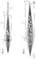
- FIG. 2Billustrates an actual example of a diffractive optical element 12 created in accordance with Equation (3).
- FIG. 2Cillustrates the simulated ring intensity 25 and the measured intensity pattern 29 of the element 12 in FIG. 2B .
- a refractive equivalent in accordance with Equation (3) of the phase matching diffractive 12may be alternately employed.
- This phase matching coupler 12is not a true beam shaper, since each point in the input plane is mapped into more than one point in the output plane because of the axial singularity. Unlike a diffuser, each point in the input plane is not mapped to every point in the output plane.
- the phase matching coupler 12allows the desired angular distribution to be substantially maintained along a portion of the fiber. This may be quantified by measuring the amount of power within a certain radius of the fiber at a certain distance along the fiber.
- the phase matching of the present inventionallows more power to be contained within the desired radii for a longer distance than methods not employing phase matching. For example, by aligning the coupler and a GRIN fiber along the same axis, using a 850 nm source, and matching both the phase and the amplitude, the encircled energy can be maintained to less than 12.5% is a radius of less than 4.5 microns and 75% for a radius less than 15 microns, with no power in the fiber center, for over 6 m.
- the light from the coupleris input to the fiber traveling in a circular direction, i.e., the path of the light down the fiber forms a corkscrew. Such traversal is opposed to the linear travel normally occurring down the fiber.
- the input distribution, typically annular, of the input lightis maintained along the fiber. Without the phase matching, while the initial input light has the desired shape, this shape is not retained throughout the traversal of the fiber. Therefore, more modal dispersion will be present, with more light in the center of the fiber, if phase matching is not used.
- the phase matching coupler 12In addition to efficiently coupling the light into the fiber, the phase matching coupler 12 also reduces the power being fedback into the light source 10 . Since the phases are matched, and the reflected light will not have the same phase as it did when originally incident on the phase matching coupler 12 , the phase matching coupler 12 will not return the light back to the light source as it came. In other words, when the reflected light traverses the system, it will be further deflected by the phase matching coupler 12 , thereby reducing the power fedback into the light source 10 .
- phase matching coupler 12only operates sufficiently when the phase matching coupler 12 is far enough away from the fiber so that the phase is sufficiently changed to prevent being redirected in the same manner.
- the phase matching coupler 12is placed in contact with the end of the fiber, while the coupler will still serve to maintain the input distribution, since the reflected light will have essentially the same phase as the input light, the light will be returned substantially back to the light source as it came.
- the phase matching coupler 12is placed at least roughly three times the diameter of the beam incident on the fiber, there is sufficient alteration of the phase due to traversal that the reflect light incident on the phase matching coupler 12 will be further deflected.
- a lens 30in addition to the phase matching coupler 12 as shown in FIG. 3 .
- This lens 30is used to shape the light to provide additional reduction in the power fedback to the light source.
- the lens 30is preferably a diffractive surface that is a combination of a lens function having radially symmetric terms with a negative axicon function.
- the lens 30may simply form a ring, since the phase matching coupler will prevent the light from being retraced.
- the lens 30is on a first surface 34 of a wafer 32 .
- the phase matching coupler 12is provided on a second surface 36 of the wafer 32 , opposite the first surface.
- the thickness of the wafer 32controls the numerical aperture of the image.
- the phase matching coupler 12may be formed on the same surface as the lens 30 .
- the lens 30allows an annular intensity ring to be optimized for the particular fiber 14 . Also, by forming this ring prior to the phase matching coupler 12 , a smaller radial segment of the phase matching coupler is used. As can be seen from equation (2), as m increases, the amount of phase twist increases. Thus, rays at the center of the phase matching coupler 12 receive a larger skew angle that rays at the edge of the phase matching coupler. By shaping the light into an annulus, this central portion is avoided, reducing the aberrations introduced by the phase matching coupler 12 . Again, the light reflected back from the fiber 14 will not have the same phase as the light incident on the phase matching coupler 12 , so the light will be further deflected by the phase matching coupler 12 . Since the deflection angles are now altered from that of the light source, the lens 30 will not focus the light back onto the light source, but will further deflect the light away from the light source.
- phase matching coupler 12is not used, only a reciprocal, phase sensitive system 40 .
- An optical elementwill map an optical distribution, i.e., amplitude and phase distribution in an input plane to an output plane. If an optical element is a reciprocal optical, it will map the same optical distribution in an output plane back to the original optical distribution in the input plane, as long as the light has the same phase and intensity profile.
- Optical systems that perform one-to-one mapping, such as an imaging lensare reciprocal, but are also phase insensitive when performing a mapping between an object plane and an image plane, i.e., a change in phase will not affect the mapping between the image and object planes.
- optical systemssuch as those that perform a one to many mapping, i.e., in which one point in the input plane is mapped to more than one point in the output plane, while reciprocal, are typically phase sensitive. In other words, a phase change will alter how the light in the output plane is returned to the input plane.
- An example of such a systemis a negative axicon.
- this system 40also creates an intensity ring on the plane at which the fiber 14 is located.
- the reflection from the fibercreates a ring back onto the system 40 , but the phase of the light has been altered due to the reflection.
- This change in phaseresults in the light traversing the system 40 having an increased diameter of the ring in the object plane, rather than returning the ring to the point source of the light source.
- This increased diameterresults in most of the light missing the input of the light source, significantly reducing feedback.
- Any other reciprocal, phase sensitive systemthat results in most of the light avoiding the light source may be used.
- the phase matching coupler 12may still be employed in any position to increase coupling bandwidth and/or enhance the feedback suppression.
Landscapes
- Physics & Mathematics (AREA)
- General Physics & Mathematics (AREA)
- Optics & Photonics (AREA)
- Optical Couplings Of Light Guides (AREA)
- Gyroscopes (AREA)
- Paper (AREA)
- Diaphragms For Electromechanical Transducers (AREA)
- Manufacture Of Macromolecular Shaped Articles (AREA)
Abstract
Description
E(r,θ,z)∝ƒmp(r)e±jmθe±jβ
Claims (7)
Priority Applications (4)
| Application Number | Priority Date | Filing Date | Title |
|---|---|---|---|
| US12/073,748US7529446B2 (en) | 1998-09-22 | 2008-03-10 | Optical element and system using the same |
| US12/453,229US7769258B2 (en) | 1998-09-22 | 2009-05-04 | Optical element and system using the same |
| US12/805,478US8529139B2 (en) | 1998-09-22 | 2010-08-02 | Optical element and system using the same |
| US14/018,951US8821035B2 (en) | 1998-09-22 | 2013-09-05 | Optical element and system using the same |
Applications Claiming Priority (6)
| Application Number | Priority Date | Filing Date | Title |
|---|---|---|---|
| US10136798P | 1998-09-22 | 1998-09-22 | |
| US09/329,996US6530697B1 (en) | 1998-09-22 | 1999-06-11 | Multi-mode fiber coupler, system and associated methods |
| US09/614,184US6496621B1 (en) | 1998-09-22 | 2000-07-11 | Fiber coupler system and associated methods for reducing back reflections |
| US10/320,525US7221823B2 (en) | 1998-09-22 | 2002-12-17 | Fiber coupler, system and associated methods for reducing back reflections |
| US11/802,044US7343069B2 (en) | 1998-09-22 | 2007-05-18 | Optical element and system using the same |
| US12/073,748US7529446B2 (en) | 1998-09-22 | 2008-03-10 | Optical element and system using the same |
Related Parent Applications (1)
| Application Number | Title | Priority Date | Filing Date |
|---|---|---|---|
| US11/802,044ContinuationUS7343069B2 (en) | 1998-09-22 | 2007-05-18 | Optical element and system using the same |
Related Child Applications (1)
| Application Number | Title | Priority Date | Filing Date |
|---|---|---|---|
| US12/453,229ContinuationUS7769258B2 (en) | 1998-09-22 | 2009-05-04 | Optical element and system using the same |
Publications (2)
| Publication Number | Publication Date |
|---|---|
| US20080159695A1 US20080159695A1 (en) | 2008-07-03 |
| US7529446B2true US7529446B2 (en) | 2009-05-05 |
Family
ID=24460189
Family Applications (5)
| Application Number | Title | Priority Date | Filing Date |
|---|---|---|---|
| US09/614,184Expired - LifetimeUS6496621B1 (en) | 1998-09-22 | 2000-07-11 | Fiber coupler system and associated methods for reducing back reflections |
| US10/320,525Expired - LifetimeUS7221823B2 (en) | 1998-09-22 | 2002-12-17 | Fiber coupler, system and associated methods for reducing back reflections |
| US11/802,044Expired - Fee RelatedUS7343069B2 (en) | 1998-09-22 | 2007-05-18 | Optical element and system using the same |
| US12/073,748Expired - Fee RelatedUS7529446B2 (en) | 1998-09-22 | 2008-03-10 | Optical element and system using the same |
| US12/453,229Expired - Fee RelatedUS7769258B2 (en) | 1998-09-22 | 2009-05-04 | Optical element and system using the same |
Family Applications Before (3)
| Application Number | Title | Priority Date | Filing Date |
|---|---|---|---|
| US09/614,184Expired - LifetimeUS6496621B1 (en) | 1998-09-22 | 2000-07-11 | Fiber coupler system and associated methods for reducing back reflections |
| US10/320,525Expired - LifetimeUS7221823B2 (en) | 1998-09-22 | 2002-12-17 | Fiber coupler, system and associated methods for reducing back reflections |
| US11/802,044Expired - Fee RelatedUS7343069B2 (en) | 1998-09-22 | 2007-05-18 | Optical element and system using the same |
Family Applications After (1)
| Application Number | Title | Priority Date | Filing Date |
|---|---|---|---|
| US12/453,229Expired - Fee RelatedUS7769258B2 (en) | 1998-09-22 | 2009-05-04 | Optical element and system using the same |
Country Status (7)
| Country | Link |
|---|---|
| US (5) | US6496621B1 (en) |
| EP (1) | EP1264204B1 (en) |
| AT (1) | ATE295970T1 (en) |
| AU (1) | AU2001273328A1 (en) |
| CA (1) | CA2403682C (en) |
| DE (1) | DE60110901T2 (en) |
| WO (1) | WO2002005004A2 (en) |
Cited By (1)
| Publication number | Priority date | Publication date | Assignee | Title |
|---|---|---|---|---|
| US20140133802A1 (en)* | 2011-07-15 | 2014-05-15 | Enplas Corporation | Light receptacle and optical module equipped with same |
Families Citing this family (42)
| Publication number | Priority date | Publication date | Assignee | Title |
|---|---|---|---|---|
| US6905900B1 (en) | 2000-11-28 | 2005-06-14 | Finisar Corporation | Versatile method and system for single mode VCSELs |
| US7065124B2 (en) | 2000-11-28 | 2006-06-20 | Finlsar Corporation | Electron affinity engineered VCSELs |
| US6822794B2 (en)* | 2000-12-15 | 2004-11-23 | Agilent Technologies, Inc. | Diffractive optical element for providing favorable multi-mode fiber launch and reflection management |
| US6965626B2 (en) | 2002-09-03 | 2005-11-15 | Finisar Corporation | Single mode VCSEL |
| US6807336B2 (en)* | 2002-11-12 | 2004-10-19 | Agilent Technologies, Inc. | Optical lenses |
| US6813293B2 (en) | 2002-11-21 | 2004-11-02 | Finisar Corporation | Long wavelength VCSEL with tunnel junction, and implant |
| US7418016B2 (en)* | 2003-02-13 | 2008-08-26 | Avago Technologies Ecbu Ip (Singapore) Pte. Ltd. | Method and apparatus for modifying the spread of a laser beam |
| US20040222363A1 (en)* | 2003-05-07 | 2004-11-11 | Honeywell International Inc. | Connectorized optical component misalignment detection system |
| US7231114B2 (en)* | 2003-05-21 | 2007-06-12 | Ocp-Europe, Ltd. | Multimode fiber optical fiber transmission system with offset launch single mode long wavelength vertical cavity surface emitting laser transmitter |
| US20040247250A1 (en)* | 2003-06-03 | 2004-12-09 | Honeywell International Inc. | Integrated sleeve pluggable package |
| US7298942B2 (en) | 2003-06-06 | 2007-11-20 | Finisar Corporation | Pluggable optical optic system having a lens fiber stop |
| US7433381B2 (en) | 2003-06-25 | 2008-10-07 | Finisar Corporation | InP based long wavelength VCSEL |
| US7075962B2 (en) | 2003-06-27 | 2006-07-11 | Finisar Corporation | VCSEL having thermal management |
| US7277461B2 (en) | 2003-06-27 | 2007-10-02 | Finisar Corporation | Dielectric VCSEL gain guide |
| US7054345B2 (en) | 2003-06-27 | 2006-05-30 | Finisar Corporation | Enhanced lateral oxidation |
| US7149383B2 (en)* | 2003-06-30 | 2006-12-12 | Finisar Corporation | Optical system with reduced back reflection |
| US6961489B2 (en) | 2003-06-30 | 2005-11-01 | Finisar Corporation | High speed optical system |
| US20060056762A1 (en)* | 2003-07-02 | 2006-03-16 | Honeywell International Inc. | Lens optical coupler |
| US20050013542A1 (en)* | 2003-07-16 | 2005-01-20 | Honeywell International Inc. | Coupler having reduction of reflections to light source |
| US7210857B2 (en) | 2003-07-16 | 2007-05-01 | Finisar Corporation | Optical coupling system |
| US20050013539A1 (en)* | 2003-07-17 | 2005-01-20 | Honeywell International Inc. | Optical coupling system |
| US6887801B2 (en) | 2003-07-18 | 2005-05-03 | Finisar Corporation | Edge bead control method and apparatus |
| US7031363B2 (en) | 2003-10-29 | 2006-04-18 | Finisar Corporation | Long wavelength VCSEL device processing |
| KR100560387B1 (en)* | 2003-12-24 | 2006-03-13 | 한국전자통신연구원 | Single / multi mode converter, and optical code division multiple access system using the same |
| US7477815B2 (en)* | 2004-05-22 | 2009-01-13 | Ocp-Europe, Ltd | Multi-mode fiber, optical fiber transmission system with offset-launch, single-mode, long-wavelength, vertical cavity surface emitting laser transmitter |
| US8588203B2 (en) | 2004-06-04 | 2013-11-19 | Qualcomm Incorporated | Wireless communication system with improved broadcast coverage |
| US8244085B2 (en)* | 2004-07-02 | 2012-08-14 | Finisar Corporation | Optical transceiver interface for multimode fibers |
| KR100810312B1 (en)* | 2006-02-07 | 2008-03-04 | 삼성전자주식회사 | Multichannel Bidirectional Optical Transceiver |
| US7802930B2 (en) | 2008-03-04 | 2010-09-28 | Jds Uniphase Corporation | Low-noise optical transmitter |
| US20090252192A1 (en)* | 2008-04-08 | 2009-10-08 | Jds Uniphase Corporation | Reduced feedback optical transmitter |
| US8019233B2 (en)* | 2008-05-30 | 2011-09-13 | Avago Technologies Fiber Ip (Singapore) Pte. Ltd. | Method and apparatus for using a hologram to control the optical field distribution of light generated by a light source and launched into an end of an optical waveguide |
| US7796850B2 (en)* | 2008-06-11 | 2010-09-14 | Jds Uniphase Corporation | Multiple-pathway optical transmitter |
| US8442365B2 (en)* | 2009-06-26 | 2013-05-14 | Jds Uniphase Corporation | Optical subassembly for coupling light into an optical waveguide |
| TWI588560B (en) | 2012-04-05 | 2017-06-21 | 布萊恩荷登視覺協會 | Lens, device, method and system for refractive error |
| US9201250B2 (en) | 2012-10-17 | 2015-12-01 | Brien Holden Vision Institute | Lenses, devices, methods and systems for refractive error |
| CA2887655C (en) | 2012-10-17 | 2021-11-02 | Brien Holden Vision Institute | Lenses, devices, methods and systems for refractive error |
| CN105527715B (en)* | 2015-08-13 | 2019-02-22 | 嘉兴驭光光电科技有限公司 | An optical system with adjustable light divergence angle using diffractive optical elements combined with lenses |
| US10451889B2 (en) | 2015-10-22 | 2019-10-22 | Avago Technologies International Sales Pte. Limited | Optical communications module having an optics system that improves link performance, and methods |
| CN106886072B (en)* | 2015-12-15 | 2019-07-19 | 华为技术有限公司 | An integrally formed coupling module |
| US9841571B1 (en)* | 2017-01-27 | 2017-12-12 | Foxconn Interconnect Technology Limited | Optical coupling system that reduces back reflection and improves mode matching in forward optical coupling using perturbations at a reflective surface |
| US10007072B1 (en)* | 2017-02-28 | 2018-06-26 | Foxconn Interconnect Technology Limited | Optical coupling system having a perturbed curved optical surface that reduces back reflection and improves mode matching in forward optical coupling |
| EP3594725A4 (en)* | 2017-03-07 | 2020-12-16 | Nippon Sheet Glass Company, Limited | Optical component and method for producing optical component |
Citations (32)
| Publication number | Priority date | Publication date | Assignee | Title |
|---|---|---|---|---|
| US3809455A (en) | 1971-09-24 | 1974-05-07 | Siemens Ag | Coupling device for optical wave guides |
| US4045120A (en) | 1974-12-20 | 1977-08-30 | Thomson-Csf | Coupler for optical communication system |
| US4709413A (en) | 1982-09-10 | 1987-11-24 | American Telephone And Telegraph Company, At&T Bell Laboratories | Bidirectional fiber optic systems |
| US4799755A (en) | 1987-12-21 | 1989-01-24 | General Electric Company | Laser materials processing with a lensless fiber optic output coupler |
| US4834484A (en) | 1987-07-09 | 1989-05-30 | University Of Houston-University Park | Optical fiber coupler including refractive means for producing an annular beam |
| US4865409A (en) | 1987-09-30 | 1989-09-12 | Siemens Aktiengesellschaft | Coupling arrangement for coupling light of a semiconductor laser diode into a multimode glass fiber |
| US5052772A (en)* | 1989-11-27 | 1991-10-01 | Pioneer Electronic Corporation | Fiber type light wave-length converting apparatus |
| JPH0434505A (en) | 1990-05-31 | 1992-02-05 | Fujitsu Ltd | Optical waveguide device and its manufacturing method |
| US5113244A (en) | 1991-02-06 | 1992-05-12 | General Dynamics Corporation, Electronics Division | Fiber optic combiner/splitter |
| US5117472A (en) | 1990-12-28 | 1992-05-26 | At&T Bell Laboratories | Optical coupler with mode-mixing refractive microparticles |
| GB2252843A (en) | 1991-01-17 | 1992-08-19 | Atomic Energy Authority Uk | Diffractive focussing means |
| US5243681A (en) | 1992-04-13 | 1993-09-07 | Amp Incorporated | Aperture disk attenuator for laser diode connector |
| US5278679A (en) | 1992-08-03 | 1994-01-11 | Davis Jeffrey A | Sub-diffraction limited focusing lenses |
| EP0595449A1 (en) | 1992-10-30 | 1994-05-04 | Sumitomo Electric Industries, Limited | Semiconductor laser module |
| US5381499A (en) | 1992-10-06 | 1995-01-10 | Matsushita Electric Industrial Co., Ltd. | Light-emitting and light-receiving assembly and method of manufacture thereof |
| US5405659A (en) | 1993-03-05 | 1995-04-11 | University Of Puerto Rico | Method and apparatus for removing material from a target by use of a ring-shaped elliptical laser beam and depositing the material onto a substrate |
| US5416862A (en) | 1993-04-07 | 1995-05-16 | At&T Corp. | Lightwave transmission system using selected optical modes |
| US5504826A (en) | 1994-03-08 | 1996-04-02 | Nec Corporation | Optical module for subcarrier multiplexed optical transmission system |
| US5638396A (en) | 1994-09-19 | 1997-06-10 | Textron Systems Corporation | Laser ultrasonics-based material analysis system and method |
| US5661835A (en) | 1995-01-19 | 1997-08-26 | Sumitomo Electric Industries, Ltd. | Optical composite module and method of assembling the same |
| US5696862A (en) | 1994-11-17 | 1997-12-09 | Robert Bosch Gmbh | Optical transmitting and receiving device having a surface-emitting laser |
| US5763870A (en)* | 1996-12-13 | 1998-06-09 | Hewlett-Packard Company | Method and system for operating a laser device employing an integral power-regulation sensor |
| US5898802A (en) | 1997-03-27 | 1999-04-27 | Cogent Light Technologies, Inc. | Coupling method and apparatus for coupling polymer fibers to a light source for improving power handling capabilities of the polymer fibers |
| US5963696A (en) | 1996-09-20 | 1999-10-05 | Sumitomo Electric Industries, Ltd. | Method of producing a semiconductor laser module |
| WO2000013051A1 (en) | 1998-08-31 | 2000-03-09 | Digital Optics Corporation | Diffractive vertical cavity surface emitting laser power monitor and system |
| US6064786A (en) | 1996-03-08 | 2000-05-16 | Hewlett-Packard Company | Multimode communications systems and method using same |
| US6243508B1 (en) | 1999-06-01 | 2001-06-05 | Picolight Incorporated | Electro-opto-mechanical assembly for coupling a light source or receiver to an optical waveguide |
| US6264377B1 (en) | 1998-03-06 | 2001-07-24 | Matsushita Electric Industrial Co., Ltd. | Bidirectional optical semiconductor apparatus |
| US6504975B1 (en) | 1998-09-17 | 2003-01-07 | Matsushita Electric Industrial Co., Ltd. | Coupling lens and semiconductor laser module |
| US6600845B1 (en) | 1999-10-18 | 2003-07-29 | Digital Optics Corporation | Integrated parallel transmitter |
| US6822794B2 (en)* | 2000-12-15 | 2004-11-23 | Agilent Technologies, Inc. | Diffractive optical element for providing favorable multi-mode fiber launch and reflection management |
| US7149383B2 (en)* | 2003-06-30 | 2006-12-12 | Finisar Corporation | Optical system with reduced back reflection |
Family Cites Families (4)
| Publication number | Priority date | Publication date | Assignee | Title |
|---|---|---|---|---|
| US643508A (en)* | 1899-02-21 | 1900-02-13 | Manander Mott Johnson | Thermostatic governor for incubators. |
| JP3294870B2 (en)* | 1991-07-04 | 2002-06-24 | 旭光学工業株式会社 | Zoom lens |
| EP0595499B1 (en) | 1992-10-28 | 1998-09-09 | Sims Portex, Inc. | Suction catheter assemblies |
| JPH09216266A (en) | 1996-02-13 | 1997-08-19 | Toyo Mach & Metal Co Ltd | Control method of injection molding machine |
- 2000
- 2000-07-11USUS09/614,184patent/US6496621B1/ennot_activeExpired - Lifetime
- 2001
- 2001-07-10WOPCT/US2001/021761patent/WO2002005004A2/enactiveIP Right Grant
- 2001-07-10CACA002403682Apatent/CA2403682C/ennot_activeExpired - Fee Related
- 2001-07-10AUAU2001273328Apatent/AU2001273328A1/ennot_activeAbandoned
- 2001-07-10DEDE60110901Tpatent/DE60110901T2/ennot_activeExpired - Lifetime
- 2001-07-10EPEP01952595Apatent/EP1264204B1/ennot_activeExpired - Lifetime
- 2001-07-10ATAT01952595Tpatent/ATE295970T1/ennot_activeIP Right Cessation
- 2002
- 2002-12-17USUS10/320,525patent/US7221823B2/ennot_activeExpired - Lifetime
- 2007
- 2007-05-18USUS11/802,044patent/US7343069B2/ennot_activeExpired - Fee Related
- 2008
- 2008-03-10USUS12/073,748patent/US7529446B2/ennot_activeExpired - Fee Related
- 2009
- 2009-05-04USUS12/453,229patent/US7769258B2/ennot_activeExpired - Fee Related
Patent Citations (36)
| Publication number | Priority date | Publication date | Assignee | Title |
|---|---|---|---|---|
| US3809455A (en) | 1971-09-24 | 1974-05-07 | Siemens Ag | Coupling device for optical wave guides |
| US4045120A (en) | 1974-12-20 | 1977-08-30 | Thomson-Csf | Coupler for optical communication system |
| US4709413A (en) | 1982-09-10 | 1987-11-24 | American Telephone And Telegraph Company, At&T Bell Laboratories | Bidirectional fiber optic systems |
| US4834484A (en) | 1987-07-09 | 1989-05-30 | University Of Houston-University Park | Optical fiber coupler including refractive means for producing an annular beam |
| US4865409A (en) | 1987-09-30 | 1989-09-12 | Siemens Aktiengesellschaft | Coupling arrangement for coupling light of a semiconductor laser diode into a multimode glass fiber |
| US4799755A (en) | 1987-12-21 | 1989-01-24 | General Electric Company | Laser materials processing with a lensless fiber optic output coupler |
| US5052772A (en)* | 1989-11-27 | 1991-10-01 | Pioneer Electronic Corporation | Fiber type light wave-length converting apparatus |
| JPH0434505A (en) | 1990-05-31 | 1992-02-05 | Fujitsu Ltd | Optical waveguide device and its manufacturing method |
| US5117472A (en) | 1990-12-28 | 1992-05-26 | At&T Bell Laboratories | Optical coupler with mode-mixing refractive microparticles |
| GB2252843A (en) | 1991-01-17 | 1992-08-19 | Atomic Energy Authority Uk | Diffractive focussing means |
| US5113244A (en) | 1991-02-06 | 1992-05-12 | General Dynamics Corporation, Electronics Division | Fiber optic combiner/splitter |
| US5243681A (en) | 1992-04-13 | 1993-09-07 | Amp Incorporated | Aperture disk attenuator for laser diode connector |
| US5278679A (en) | 1992-08-03 | 1994-01-11 | Davis Jeffrey A | Sub-diffraction limited focusing lenses |
| US5381499A (en) | 1992-10-06 | 1995-01-10 | Matsushita Electric Industrial Co., Ltd. | Light-emitting and light-receiving assembly and method of manufacture thereof |
| EP0595449A1 (en) | 1992-10-30 | 1994-05-04 | Sumitomo Electric Industries, Limited | Semiconductor laser module |
| US5388171A (en)* | 1992-10-30 | 1995-02-07 | Sumitomo Electric Industries, Ltd. | Semiconductor laser module |
| US5405659A (en) | 1993-03-05 | 1995-04-11 | University Of Puerto Rico | Method and apparatus for removing material from a target by use of a ring-shaped elliptical laser beam and depositing the material onto a substrate |
| US5557471A (en) | 1993-03-05 | 1996-09-17 | University Of Puerto Rico | Lens for depositing target material on a substrate |
| US5416862A (en) | 1993-04-07 | 1995-05-16 | At&T Corp. | Lightwave transmission system using selected optical modes |
| US5504826A (en) | 1994-03-08 | 1996-04-02 | Nec Corporation | Optical module for subcarrier multiplexed optical transmission system |
| US5793489A (en) | 1994-09-19 | 1998-08-11 | Textron System Corporation | Ultrasonic-based material analysis using an annular impulse beam |
| US5638396A (en) | 1994-09-19 | 1997-06-10 | Textron Systems Corporation | Laser ultrasonics-based material analysis system and method |
| US5696862A (en) | 1994-11-17 | 1997-12-09 | Robert Bosch Gmbh | Optical transmitting and receiving device having a surface-emitting laser |
| US5661835A (en) | 1995-01-19 | 1997-08-26 | Sumitomo Electric Industries, Ltd. | Optical composite module and method of assembling the same |
| US6064786A (en) | 1996-03-08 | 2000-05-16 | Hewlett-Packard Company | Multimode communications systems and method using same |
| US5963696A (en) | 1996-09-20 | 1999-10-05 | Sumitomo Electric Industries, Ltd. | Method of producing a semiconductor laser module |
| US5763870A (en)* | 1996-12-13 | 1998-06-09 | Hewlett-Packard Company | Method and system for operating a laser device employing an integral power-regulation sensor |
| US5898802A (en) | 1997-03-27 | 1999-04-27 | Cogent Light Technologies, Inc. | Coupling method and apparatus for coupling polymer fibers to a light source for improving power handling capabilities of the polymer fibers |
| US6264377B1 (en) | 1998-03-06 | 2001-07-24 | Matsushita Electric Industrial Co., Ltd. | Bidirectional optical semiconductor apparatus |
| WO2000013051A1 (en) | 1998-08-31 | 2000-03-09 | Digital Optics Corporation | Diffractive vertical cavity surface emitting laser power monitor and system |
| US6504975B1 (en) | 1998-09-17 | 2003-01-07 | Matsushita Electric Industrial Co., Ltd. | Coupling lens and semiconductor laser module |
| US6243508B1 (en) | 1999-06-01 | 2001-06-05 | Picolight Incorporated | Electro-opto-mechanical assembly for coupling a light source or receiver to an optical waveguide |
| US6600845B1 (en) | 1999-10-18 | 2003-07-29 | Digital Optics Corporation | Integrated parallel transmitter |
| US6822794B2 (en)* | 2000-12-15 | 2004-11-23 | Agilent Technologies, Inc. | Diffractive optical element for providing favorable multi-mode fiber launch and reflection management |
| US6856460B2 (en) | 2000-12-15 | 2005-02-15 | Agilent Technologies, Inc. | Diffractive optical element for providing favorable multi-mode fiber launch and reflection management |
| US7149383B2 (en)* | 2003-06-30 | 2006-12-12 | Finisar Corporation | Optical system with reduced back reflection |
Cited By (2)
| Publication number | Priority date | Publication date | Assignee | Title |
|---|---|---|---|---|
| US20140133802A1 (en)* | 2011-07-15 | 2014-05-15 | Enplas Corporation | Light receptacle and optical module equipped with same |
| US9213153B2 (en)* | 2011-07-15 | 2015-12-15 | Enplas Corporation | Light receptacle and optical module equipped with same |
Also Published As
| Publication number | Publication date |
|---|---|
| EP1264204B1 (en) | 2005-05-18 |
| CA2403682A1 (en) | 2002-01-17 |
| US20030072526A1 (en) | 2003-04-17 |
| US20070223094A1 (en) | 2007-09-27 |
| AU2001273328A1 (en) | 2002-01-21 |
| CA2403682C (en) | 2009-10-06 |
| US6496621B1 (en) | 2002-12-17 |
| EP1264204A2 (en) | 2002-12-11 |
| ATE295970T1 (en) | 2005-06-15 |
| WO2002005004A2 (en) | 2002-01-17 |
| DE60110901T2 (en) | 2006-03-23 |
| US7221823B2 (en) | 2007-05-22 |
| DE60110901D1 (en) | 2005-06-23 |
| WO2002005004A3 (en) | 2002-07-18 |
| US20090226134A1 (en) | 2009-09-10 |
| US20080159695A1 (en) | 2008-07-03 |
| US7769258B2 (en) | 2010-08-03 |
| US7343069B2 (en) | 2008-03-11 |
Similar Documents
| Publication | Publication Date | Title |
|---|---|---|
| US7529446B2 (en) | Optical element and system using the same | |
| US6530697B1 (en) | Multi-mode fiber coupler, system and associated methods | |
| US8821035B2 (en) | Optical element and system using the same | |
| US7099535B2 (en) | Small mode-field fiber lens | |
| JP2006522943A (en) | A practical way to reduce losses associated with beam shaping and fitting external sources and optics to thin silicon waveguides | |
| US6600845B1 (en) | Integrated parallel transmitter | |
| US11693185B2 (en) | Optical connector with tilted mirror | |
| CN108387978B (en) | Optical coupling system and optical coupling method | |
| US5301249A (en) | Catoptric coupling to an optical fiber | |
| US6654518B1 (en) | Tap output collimator | |
| US20010051021A1 (en) | Phase mask consisting of an array of multiple diffractive elements for simultaneous accurate fabrication of large arrays of optical couplers and method for making same | |
| CA1321499C (en) | Laser diode to fiber reflective coupling | |
| US7011455B2 (en) | Opto-electronic TO-package and method for laser | |
| US6721108B2 (en) | Optical lens device assembly | |
| JP2548767B2 (en) | Pseudo wavelength dispersion generator | |
| CN1771446A (en) | A Practical Approach to Beam Shaping and Reducing Losses Induced by Connecting External Light Sources and Optics to Thin Silicon Waveguides | |
| CN116990908A (en) | Multi-core optical fiber core-to-core exchange coupler based on self-focusing optical fiber mirror | |
| JPH0414762B2 (en) | ||
| Young | Optical Waveguides |
Legal Events
| Date | Code | Title | Description |
|---|---|---|---|
| STCF | Information on status: patent grant | Free format text:PATENTED CASE | |
| AS | Assignment | Owner name:DIGITALOPTICS CORPORATION EAST, NORTH CAROLINA Free format text:CHANGE OF NAME;ASSIGNOR:TESSERA NORTH AMERICA, INC.;REEL/FRAME:027768/0541 Effective date:20110701 | |
| REMI | Maintenance fee reminder mailed | ||
| FPAY | Fee payment | Year of fee payment:4 | |
| SULP | Surcharge for late payment | ||
| AS | Assignment | Owner name:FLIR SYSTEMS TRADING BELGIUM BVBA, BELGIUM Free format text:ASSIGNMENT OF ASSIGNORS INTEREST;ASSIGNOR:DIGITALOPTICS CORPORATION EAST;REEL/FRAME:032827/0362 Effective date:20130808 | |
| AS | Assignment | Owner name:AVAGO TECHNOLOGIES GENERAL IP (SINGAPORE) PTE. LTD Free format text:ASSIGNMENT OF ASSIGNORS INTEREST;ASSIGNOR:FLIR SYSTEMS TRADING BELGIUM BVBA;REEL/FRAME:036126/0092 Effective date:20140827 | |
| AS | Assignment | Owner name:DIGITALOPTICS CORPORATION EAST, NORTH CAROLINA Free format text:CORRECTIVE ASSIGNMENT TO CORRECT THE PATENT NO. 7817833 PREVIOUSLY RECORDED AT REEL: 027768 FRAME: 0541. ASSIGNOR(S) HEREBY CONFIRMS THE ASSIGNMENT;ASSIGNOR:TESSERA NORTH AMERICA, INC.;REEL/FRAME:036733/0896 Effective date:20110701 | |
| AS | Assignment | Owner name:BANK OF AMERICA, N.A., AS COLLATERAL AGENT, NORTH CAROLINA Free format text:PATENT SECURITY AGREEMENT;ASSIGNOR:AVAGO TECHNOLOGIES GENERAL IP (SINGAPORE) PTE. LTD.;REEL/FRAME:037808/0001 Effective date:20160201 Owner name:BANK OF AMERICA, N.A., AS COLLATERAL AGENT, NORTH Free format text:PATENT SECURITY AGREEMENT;ASSIGNOR:AVAGO TECHNOLOGIES GENERAL IP (SINGAPORE) PTE. LTD.;REEL/FRAME:037808/0001 Effective date:20160201 | |
| FPAY | Fee payment | Year of fee payment:8 | |
| AS | Assignment | Owner name:AVAGO TECHNOLOGIES GENERAL IP (SINGAPORE) PTE. LTD., SINGAPORE Free format text:TERMINATION AND RELEASE OF SECURITY INTEREST IN PATENTS;ASSIGNOR:BANK OF AMERICA, N.A., AS COLLATERAL AGENT;REEL/FRAME:041710/0001 Effective date:20170119 Owner name:AVAGO TECHNOLOGIES GENERAL IP (SINGAPORE) PTE. LTD Free format text:TERMINATION AND RELEASE OF SECURITY INTEREST IN PATENTS;ASSIGNOR:BANK OF AMERICA, N.A., AS COLLATERAL AGENT;REEL/FRAME:041710/0001 Effective date:20170119 | |
| AS | Assignment | Owner name:AVAGO TECHNOLOGIES INTERNATIONAL SALES PTE. LIMITE Free format text:MERGER;ASSIGNOR:AVAGO TECHNOLOGIES GENERAL IP (SINGAPORE) PTE. LTD.;REEL/FRAME:047195/0827 Effective date:20180509 | |
| AS | Assignment | Owner name:AVAGO TECHNOLOGIES INTERNATIONAL SALES PTE. LIMITE Free format text:CORRECTIVE ASSIGNMENT TO CORRECT THE EFFECTIVE DATE OF MERGER PREVIOUSLY RECORDED AT REEL: 047195 FRAME: 0827. ASSIGNOR(S) HEREBY CONFIRMS THE MERGER;ASSIGNOR:AVAGO TECHNOLOGIES GENERAL IP (SINGAPORE) PTE. LTD.;REEL/FRAME:047924/0571 Effective date:20180905 | |
| FEPP | Fee payment procedure | Free format text:MAINTENANCE FEE REMINDER MAILED (ORIGINAL EVENT CODE: REM.); ENTITY STATUS OF PATENT OWNER: LARGE ENTITY | |
| LAPS | Lapse for failure to pay maintenance fees | Free format text:PATENT EXPIRED FOR FAILURE TO PAY MAINTENANCE FEES (ORIGINAL EVENT CODE: EXP.); ENTITY STATUS OF PATENT OWNER: LARGE ENTITY | |
| STCH | Information on status: patent discontinuation | Free format text:PATENT EXPIRED DUE TO NONPAYMENT OF MAINTENANCE FEES UNDER 37 CFR 1.362 | |
| FP | Lapsed due to failure to pay maintenance fee | Effective date:20210505 |