US7527716B2 - Connector configuration for electrochemical cells and meters for use in combination therewith - Google Patents
Connector configuration for electrochemical cells and meters for use in combination therewithDownload PDFInfo
- Publication number
- US7527716B2 US7527716B2US10/908,662US90866205AUS7527716B2US 7527716 B2US7527716 B2US 7527716B2US 90866205 AUS90866205 AUS 90866205AUS 7527716 B2US7527716 B2US 7527716B2
- Authority
- US
- United States
- Prior art keywords
- connector
- test strip
- electrode
- contact
- pads
- Prior art date
- Legal status (The legal status is an assumption and is not a legal conclusion. Google has not performed a legal analysis and makes no representation as to the accuracy of the status listed.)
- Active, expires
Links
- 238000012360testing methodMethods0.000claimsabstractdescription67
- 238000000840electrochemical analysisMethods0.000claimsabstractdescription40
- 239000012491analyteSubstances0.000claimsabstractdescription24
- 238000000926separation methodMethods0.000claimsdescription19
- 239000003153chemical reaction reagentSubstances0.000claimsdescription17
- WQZGKKKJIJFFOK-GASJEMHNSA-NGlucoseNatural productsOC[C@H]1OC(O)[C@H](O)[C@@H](O)[C@@H]1OWQZGKKKJIJFFOK-GASJEMHNSA-N0.000claimsdescription9
- 239000008103glucoseSubstances0.000claimsdescription9
- 238000005259measurementMethods0.000claimsdescription8
- 238000012545processingMethods0.000claimsdescription5
- 238000001514detection methodMethods0.000claimsdescription4
- 108090000790EnzymesProteins0.000claimsdescription3
- 102000004190EnzymesHuman genes0.000claimsdescription3
- 210000004027cellAnatomy0.000description24
- 239000000463materialSubstances0.000description16
- 238000000034methodMethods0.000description8
- 230000008901benefitEffects0.000description5
- 239000004020conductorSubstances0.000description5
- 238000004519manufacturing processMethods0.000description5
- 239000007772electrode materialSubstances0.000description4
- PCHJSUWPFVWCPO-UHFFFAOYSA-NgoldChemical compound[Au]PCHJSUWPFVWCPO-UHFFFAOYSA-N0.000description4
- 229910052737goldInorganic materials0.000description4
- 239000010931goldSubstances0.000description4
- 239000000203mixtureSubstances0.000description4
- 108010015776Glucose oxidaseProteins0.000description3
- 239000004366Glucose oxidaseSubstances0.000description3
- 230000005540biological transmissionEffects0.000description3
- 239000008280bloodSubstances0.000description3
- 210000004369bloodAnatomy0.000description3
- YAGKRVSRTSUGEY-UHFFFAOYSA-NferricyanideChemical compound[Fe+3].N#[C-].N#[C-].N#[C-].N#[C-].N#[C-].N#[C-]YAGKRVSRTSUGEY-UHFFFAOYSA-N0.000description3
- 229940116332glucose oxidaseDrugs0.000description3
- 235000019420glucose oxidaseNutrition0.000description3
- 238000003780insertionMethods0.000description3
- 230000037431insertionEffects0.000description3
- 239000007788liquidSubstances0.000description3
- 230000008569processEffects0.000description3
- 229910052709silverInorganic materials0.000description3
- 239000000758substrateSubstances0.000description3
- OKTJSMMVPCPJKN-UHFFFAOYSA-NCarbonChemical compound[C]OKTJSMMVPCPJKN-UHFFFAOYSA-N0.000description2
- KDLHZDBZIXYQEI-UHFFFAOYSA-NPalladiumChemical compound[Pd]KDLHZDBZIXYQEI-UHFFFAOYSA-N0.000description2
- 239000000853adhesiveSubstances0.000description2
- 230000001070adhesive effectEffects0.000description2
- 229910052799carbonInorganic materials0.000description2
- 239000011248coating agentSubstances0.000description2
- 238000000576coating methodMethods0.000description2
- 238000000151depositionMethods0.000description2
- 230000008021depositionEffects0.000description2
- 238000003487electrochemical reactionMethods0.000description2
- BASFCYQUMIYNBI-UHFFFAOYSA-NplatinumChemical compound[Pt]BASFCYQUMIYNBI-UHFFFAOYSA-N0.000description2
- 229920000139polyethylene terephthalatePolymers0.000description2
- 239000005020polyethylene terephthalateSubstances0.000description2
- 239000004332silverSubstances0.000description2
- 239000004642PolyimideSubstances0.000description1
- 206010036790Productive coughDiseases0.000description1
- BQCADISMDOOEFD-UHFFFAOYSA-NSilverChemical compound[Ag]BQCADISMDOOEFD-UHFFFAOYSA-N0.000description1
- 229910021607Silver chlorideInorganic materials0.000description1
- CDBYLPFSWZWCQE-UHFFFAOYSA-LSodium CarbonateChemical compound[Na+].[Na+].[O-]C([O-])=OCDBYLPFSWZWCQE-UHFFFAOYSA-L0.000description1
- 230000009471actionEffects0.000description1
- 238000004458analytical methodMethods0.000description1
- 238000013459approachMethods0.000description1
- 239000003125aqueous solventSubstances0.000description1
- 238000005452bendingMethods0.000description1
- 235000013361beverageNutrition0.000description1
- 210000001124body fluidAnatomy0.000description1
- 238000010276constructionMethods0.000description1
- 238000003869coulometryMethods0.000description1
- 230000007423decreaseEffects0.000description1
- 238000013461designMethods0.000description1
- 230000001066destructive effectEffects0.000description1
- 238000000835electrochemical detectionMethods0.000description1
- 230000005518electrochemistryEffects0.000description1
- 229940088598enzymeDrugs0.000description1
- 210000003722extracellular fluidAnatomy0.000description1
- 239000011152fibreglassSubstances0.000description1
- 239000012530fluidSubstances0.000description1
- 239000011521glassSubstances0.000description1
- 239000012811non-conductive materialSubstances0.000description1
- 229910052763palladiumInorganic materials0.000description1
- 230000037361pathwayEffects0.000description1
- 229910052697platinumInorganic materials0.000description1
- 229920000515polycarbonatePolymers0.000description1
- 239000004417polycarbonateSubstances0.000description1
- 229920000728polyesterPolymers0.000description1
- -1polyethylene terephthalatePolymers0.000description1
- 229920001721polyimidePolymers0.000description1
- 238000003908quality control methodMethods0.000description1
- 230000004044responseEffects0.000description1
- 210000003296salivaAnatomy0.000description1
- HKZLPVFGJNLROG-UHFFFAOYSA-Msilver monochlorideChemical compound[Cl-].[Ag+]HKZLPVFGJNLROG-UHFFFAOYSA-M0.000description1
- 230000002269spontaneous effectEffects0.000description1
- 210000003802sputumAnatomy0.000description1
- 208000024794sputumDiseases0.000description1
- 239000000126substanceSubstances0.000description1
- 238000004381surface treatmentMethods0.000description1
- 210000002700urineAnatomy0.000description1
- 239000002351wastewaterSubstances0.000description1
Images


Classifications
- G—PHYSICS
- G01—MEASURING; TESTING
- G01N—INVESTIGATING OR ANALYSING MATERIALS BY DETERMINING THEIR CHEMICAL OR PHYSICAL PROPERTIES
- G01N27/00—Investigating or analysing materials by the use of electric, electrochemical, or magnetic means
- G01N27/26—Investigating or analysing materials by the use of electric, electrochemical, or magnetic means by investigating electrochemical variables; by using electrolysis or electrophoresis
- G01N27/403—Cells and electrode assemblies
- C—CHEMISTRY; METALLURGY
- C12—BIOCHEMISTRY; BEER; SPIRITS; WINE; VINEGAR; MICROBIOLOGY; ENZYMOLOGY; MUTATION OR GENETIC ENGINEERING
- C12Q—MEASURING OR TESTING PROCESSES INVOLVING ENZYMES, NUCLEIC ACIDS OR MICROORGANISMS; COMPOSITIONS OR TEST PAPERS THEREFOR; PROCESSES OF PREPARING SUCH COMPOSITIONS; CONDITION-RESPONSIVE CONTROL IN MICROBIOLOGICAL OR ENZYMOLOGICAL PROCESSES
- C12Q1/00—Measuring or testing processes involving enzymes, nucleic acids or microorganisms; Compositions therefor; Processes of preparing such compositions
- C12Q1/001—Enzyme electrodes
- C12Q1/004—Enzyme electrodes mediator-assisted
- G—PHYSICS
- G01—MEASURING; TESTING
- G01N—INVESTIGATING OR ANALYSING MATERIALS BY DETERMINING THEIR CHEMICAL OR PHYSICAL PROPERTIES
- G01N33/00—Investigating or analysing materials by specific methods not covered by groups G01N1/00 - G01N31/00
- G01N33/48—Biological material, e.g. blood, urine; Haemocytometers
- G01N33/483—Physical analysis of biological material
- G01N33/487—Physical analysis of biological material of liquid biological material
- G—PHYSICS
- G01—MEASURING; TESTING
- G01N—INVESTIGATING OR ANALYSING MATERIALS BY DETERMINING THEIR CHEMICAL OR PHYSICAL PROPERTIES
- G01N27/00—Investigating or analysing materials by the use of electric, electrochemical, or magnetic means
- G01N27/26—Investigating or analysing materials by the use of electric, electrochemical, or magnetic means by investigating electrochemical variables; by using electrolysis or electrophoresis
- G01N27/28—Electrolytic cell components
- G01N27/30—Electrodes, e.g. test electrodes; Half-cells
- G01N27/327—Biochemical electrodes, e.g. electrical or mechanical details for in vitro measurements
- G01N27/3271—Amperometric enzyme electrodes for analytes in body fluids, e.g. glucose in blood
- G01N27/3272—Test elements therefor, i.e. disposable laminated substrates with electrodes, reagent and channels
- Y—GENERAL TAGGING OF NEW TECHNOLOGICAL DEVELOPMENTS; GENERAL TAGGING OF CROSS-SECTIONAL TECHNOLOGIES SPANNING OVER SEVERAL SECTIONS OF THE IPC; TECHNICAL SUBJECTS COVERED BY FORMER USPC CROSS-REFERENCE ART COLLECTIONS [XRACs] AND DIGESTS
- Y10—TECHNICAL SUBJECTS COVERED BY FORMER USPC
- Y10T—TECHNICAL SUBJECTS COVERED BY FORMER US CLASSIFICATION
- Y10T156/00—Adhesive bonding and miscellaneous chemical manufacture
- Y10T156/10—Methods of surface bonding and/or assembly therefor
- Y10T156/1052—Methods of surface bonding and/or assembly therefor with cutting, punching, tearing or severing
- Y10T156/1062—Prior to assembly
- Y10T156/1074—Separate cutting of separate sheets or webs
- Y—GENERAL TAGGING OF NEW TECHNOLOGICAL DEVELOPMENTS; GENERAL TAGGING OF CROSS-SECTIONAL TECHNOLOGIES SPANNING OVER SEVERAL SECTIONS OF THE IPC; TECHNICAL SUBJECTS COVERED BY FORMER USPC CROSS-REFERENCE ART COLLECTIONS [XRACs] AND DIGESTS
- Y10—TECHNICAL SUBJECTS COVERED BY FORMER USPC
- Y10T—TECHNICAL SUBJECTS COVERED BY FORMER US CLASSIFICATION
- Y10T29/00—Metal working
- Y10T29/49—Method of mechanical manufacture
- Y10T29/49002—Electrical device making
- Y10T29/49108—Electric battery cell making
- Y10T29/49114—Electric battery cell making including adhesively bonding
- Y—GENERAL TAGGING OF NEW TECHNOLOGICAL DEVELOPMENTS; GENERAL TAGGING OF CROSS-SECTIONAL TECHNOLOGIES SPANNING OVER SEVERAL SECTIONS OF THE IPC; TECHNICAL SUBJECTS COVERED BY FORMER USPC CROSS-REFERENCE ART COLLECTIONS [XRACs] AND DIGESTS
- Y10—TECHNICAL SUBJECTS COVERED BY FORMER USPC
- Y10T—TECHNICAL SUBJECTS COVERED BY FORMER US CLASSIFICATION
- Y10T29/00—Metal working
- Y10T29/49—Method of mechanical manufacture
- Y10T29/49002—Electrical device making
- Y10T29/49117—Conductor or circuit manufacturing
Definitions
- This applicationrelates to electrochemical cells, and particularly the type of cells configured as single-use strips that are used in home testing for analytes such as glucose.
- test strips and meters for the electrochemical detection of analytes such as glucoseare known.
- the test stripthere are routinely at least two electrodes between which an electrochemical signal is generated.
- the magnitude of this signalis indicative of the amount of the analyte present in the sample.
- the signalmay be a measurement of current, that is an amperometric signal; a measurement of potential, that is a potentiometric signal, or a measurement of charge, that is a coulometric signal.
- the electrodes which make actual contact with the sample to be evaluated for the presence and/or amount of analyteare connected to conductive leads, which in turn are connected to connectors, through which the strip is connected to a meter apparatus for detection and processing of the electrochemical signal to provide an indication of presence and/or amount of analyte to the user.
- a separate meterallows the use of disposable electrode strips, and reusable electronics.
- the stripis a flat rectangular strip with a top and a bottom major surface, two long sides, and two short sides or ends.
- Sampleis generally introduced at one end, and the connectors are generally disposed at the opposite end.
- One lead/connector combinationis provided for each electrode, and the leads and the associated connectors are generally disposed in a side-by side orientation parallel to the long sides of the strip.
- the present inventionprovides a substantially planar electrochemical test strip for determination of the presence and/or quantity of an analyte in a sample, comprising:
- contact pad or pads of the second connectorare between the contact pads of the first connector when viewed in the plane of the test strip.
- the present inventionfurther provides a meter having contacts for use with the electrochemical test strip, and a combination of a meter and an electrochemical test strip.
- FIGS. 1A and Bshows an isometric view of an electrochemical cell produced by the method of this invention.
- FIGS. 2-A and Bshow embodiments of connector configurations of electrochemical test cells of the invention.
- FIG. 3shows an electrochemical test cell of the invention.
- FIG. 4shows an electrochemical test cell of the invention.
- FIG. 5shows one electrode layer of an electrochemical test cell of the invention.
- FIG. 6shows a process for making electrochemical test cells of the invention.
- FIGS. 7A-Cshow intermediate stages in a method of manufacture of electrochemical test cells of the invention.
- FIG. 8shows an exterior view of a meter in accordance with the invention.
- FIGS. 9A-Cshow the connection of a electrochemical test strip to a meter in accordance with an embodiment of the invention.
- FIGS. 10A-Cshow the connection of a electrochemical test strip to a meter in accordance with another embodiment of the invention.
- the present inventionprovides electrochemical test strips that have a configuration for the connectors that provide substantial advantages over known connector configurations.
- the inventionalso provides meters that are adapted for receiving such electrochemical test strips, and combinations of meters and test strips.
- the connector configuration of the inventionis suitably employed in electrochemical test strips for other electrochemically detectable analytes.
- analyterefers to substance for which a test is performed.
- the testmay be qualitative (a measurable signal associated with the analyte is or is not detectable), semi-quantititave (a measurable signal above or below a specified threshold provides a positive or negative indication) or quantitative (a numerical value of the amount of analyte is provided).
- determination of an analyteencompasses determination of the presence or amount of an analyte in any of these types of tests.
- samplerefers to any type of sample in which the determination of an analyte is desirable. This would include without limitation bodily fluids, for example blood, urine, sputum, interstitial fluid, or saliva; commercial products, but other samples including beverages such as wine or soda, waste water, and other liquids may also be tested using the invention. Samples that are not liquids may be suspended or dissolved in an aqueous solvent.
- the term “electrode”refers to a conductive element which in use is in contact with the sample. Two or more electrodes in contact with the same sample for an electrochemical cell. In a two electrode system, the electrodes are conventionally referred to a sa working and counter electrode. In a three electrode system, the third electrode is conventionally referred to as a reference electrode.
- the electrode material employedis selected consistent with the nature of the analyte and the electrochemical reactions to be monitored, and suitable electrode materials for specific analytes are known in the art. Non-limiting examples of electrode materials include gold, silver, PT, Ag/AgCl and conductive carbon.
- the electrodes in a given electrochemical stripmay be formed from the same material or from different materials,
- the term “connector”refers to a portion of an electrochemical strip that is designed for contact with a meter that provides any necessary electrochemical impetus to the electrochemical strip and receives input from the strip for analysis and display to the user.
- the connectorsmay be made from the same material as the electrode to which they are connected, or of different materials.
- a leadmay be made of the same material as the electrode, the same material as the connector, the same material as both the electrode and the connector or different materials from both the electrode and the connector between which the lead extends.
- the term “contact pad”refers to the portion of the connector that is actually contacted with a corresponding contact in the meter when in use.
- a connectormay have a single contact pad, in which case the contact pad may be only the terminal portion of the connector, or may be coextensive with the connector.
- the contact padare electrically isolated one from the other except for conductive paths leading through the remainder of the connector, the lead, or the electrode with which they are associated.
- the contact pad or pads of the second connectorare between the contact pads of the first connector when viewed in the plane of the test strip. This does not require that the pads are exactly coplanar, and indeed in the examples shown herein the contact pads are not coplanar. They are, however, disposed in the stated orientation when the test strip is viewed in a plan view looking towards a major surface of the electrochemical test strip.
- FIG. 1Ashows schematic representation of an embodiment of an electrochemical test cell of the invention, viewed from the sample application end.
- the cellis formed from a bottom layer 130 , a top layer 131 , and a middle layer 132 .
- the top and bottom layersare electrically conductive, at least on the surfaces facing the middle layer 132 .
- the top and bottom layers 130 , 131are an insulating substrate onto which a conductive layer has been coated.
- the middle layer 132has a notch 133 formed in one edge.
- the notch 133 , and the top and bottom layers 130 , 131together define a space into which sample is received when the electrochemical cell is in use.
- the volume of this spaceis thus defined by the thickness of the middle layer 132 and the dimensions of the notch.
- the electrochemical cellalso has connectors having contact pads thereon 134 and 135 that are attachable to a meter to provide an electrical connection between the meter and the portion of the top and bottom layers 130 , 131 that are exposed in the space for receiving a sample.
- the middle layer 132is an electrically resistive material which isolates the conductive layers, and prevents electrical conductivity between the electrically conductive top and bottom layers 130 , 131 , unless they are connected via a sample disposed in the space for receiving a sample.
- suitable materials for use as this layerinclude polyimide, polyester, polyethylene terephthalate (PET), polycarbonate, glass, fiberglass or other nonconductive materials that provide the desired support.
- the middle layer 132suitably has a thickness of 500 to 50 micrometers. Thicker materials can be used where larger sample volumes are acceptable. Thinner materials can be used, but may create difficulties in handling, and increased difficulty in drawing sample into the finished cell since this thickness determines one dimension of the sample space.
- the sample space volumeis less than 5 microliters and more preferably less than 1 microliter. In specific embodiments of the invention, the volume of the sample space is 500, 300, 200, 100 or 50 nl.
- top and bottom layers 130 , 131is selected consistent with the specific analyte that the electrochemical cell is intended to detect.
- suitable conductive electrode materialsinclude gold, carbon, silver, palladium, and platinum.
- the conductive material used in the top and bottom layers 130 , 131may be the same or they may be different from one another. In a preferred embodiment of the present invention the conductive material is gold.
- the conductive portion of the top and bottom layersis suitably a thin coating on one surface of an insulating substrate sheet. Materials used for the middle layer 132 may be used as this substrate as well.
- the electrochemical cellmay include a reagent composition disposed within the space for receiving a sample.
- this reagent compositionsuitably comprises an enzyme effective to oxidize glucose, for example glucose oxidase, and a redox mediator, for example ferricyanide.
- Reagent compositions for this purposeare known in the art, for example from U.S. Pat. No. 4,711,245 to Higgins et al. and U.S. Pat. No. 5,437,999 to Diebold et al., which are incorporated herein by reference.
- the reagentcomprises glucose oxidase and ferricyanide.
- the reagent compositionwhen present, may assist in overcoming the hydrophobicity of the sample space, so that blood or other aqueous sample can be drawn into the space by capillary action. Where a reagent is not used, surface treatment of the sample volume to reduce hydrophobicity and to facilitate sample introduction may be indicated.
- the test strip of the inventionis substantially planar. This means that the test strip has a top substantially planar surface and a bottom substantially planar surface that are substantially parallel.
- the term “substantially”is included in this statement to encompass deviations from perfect planarity and parallelness that result from manufacturing variations in the thickness of materials used across the length and width of the strip, variations in the thickness of depositions such as film, ink or adhesive depositions across the length and width of the device and the like.
- FIGS. 2A and Bshow embodiments of connector configurations in accordance with the invention.
- FIG. 2Athere are two peripherally located connectors having contact pads thereon, 141 , 141 ′ that extend from the top conductive layer and one centrally located connector having a contact pad thereon 46 extends from the bottom conductive layer.
- FIG. 2Bshows an alternative embodiment in which two peripherally located connectors having contact pads thereon, 141 , 141 ′ extend from the top conductive layer and two centrally located connectors having contact pads thereon 146 , 146 ′ extend from the bottom conductive layer.
- the connector/contact pad configurations shown in FIGS. 2A and Bprovide an important advantage in the use of disposable electrochemical test strips. Because the contact pads for the first electrode are always disposed at the periphery of the test strip, and the contact pads for the second electrode are always disposed centrally, meters can be designed which accept the strip in either of two orientations without ambiguity as to the electrode that is associated with the contacts of the meter. Such meters are discussed in greater detail below.
- FIG. 3shows a further embodiment of the electrochemical test strip of the invention.
- FIG. 3is generally similar to FIG. 2A , except that the division of the connectors having contact pads thereon 141 , 141 ′ is continued through some or all of the balance of the connector (if any) and the lead as reflected by dashed line 30 which reflects a scoring or removal of the conductive surface on the underside of layer 42 .
- FIG. 4shows a further embodiment of the electrochemical test strip of the invention.
- FIG. 4is generally similar to FIG. 2B (shown from the bottom), except that the separation of the connectors having contact pads thereon 146 , 146 ′ is continued through some or all of the balance of the connector (if any) and the lead as reflected by dashed line 40 which reflects a scoring or removal of the conductive surface on the underside of layer 44 .
- FIGS. 3 and 4The separation of connectors and leads as shown in FIGS. 3 and 4 can be used in combination in a single device.
- the connector configurations shown in FIGS. 3 and 4provide advantages in the area of fault testing prior to the application of a sample when there is (or should be) no electrical contact between the electrodes. Damage to one of the electrodes or its associated leads that extends completely across the path of electrical connection will prevent the completion of the circuit necessary for measurement. However such damage is not detectable in a conventional electrochemical strip prior to application of the sample, the electrode and its associated leads are not part of a circuit that can be measured. As shown in FIG. 5 , however, when the separation of the contact pads on connectors 141 , 141 ′ (or 146 , 146 ′) is extended, the two contact pads can be used as ends of a circuit to confirm the continuity of the area around the sample cell.
- FIG. 5shows just the electrode layer of a cell where the connectors having contact pads thereon 501 and 502 have an extended separation 550 .
- the location of the sample space 133is shown in dashed lines. If the electrical connection (for example via a conductivity measurement) is assessed between connectors having contact pads thereon 501 and 502 , a good connection will be determined provided that there is no damage to the conductive sheet that extends all the way across either leg or the loop portion of electrode layer. For example, a scratch 503 or 504 would be detected as a fail, while a scratch such as 505 would not.
- connection between the electrode portion over the sample space 133 and either one of the connectors having contact pads thereon 501 or 502is sufficient for a valid test result, this provides an easily achieved, non-destructive form of quality control which is actually more rigorous than the requirements of the operative device.
- Electrochemical test strips in accordance with the inventioncan be manufactured using the method as illustrated in FIGS. 6 , 7 A and 7 B and as described in U.S. patent application Ser. No. 10/909,656 filed May 20, 2005, which is incorporated by reference.
- Step OneAn electrically resistive sheet is provided.
- the electrically resistive sheet 61is coated with an adhesive on both major surfaces thereof.
- Step TwoAs shown in detail in FIG. 7A , two registration holes 71 are provided to the electrically resistive sheet 61 from step one for manufacturing alignment and do not become part of the final device.
- the electrically resistive sheet 61is placed into a die assembly (not shown) wherein the die assembly aligns the electrically-resistive sheet via the two registration holes.
- the electrically resistive sheet 61is then punched thereby forming a punched electrically-resistive sheet 62 with two large and two small openings through the sheet.
- the large openings 72are the openings through which the electrical connectors will be formed.
- the small openings 73are the openings across which the notching opening, and the vent opening will be made define the sample space.
- Step ThreeThe punched electrically resistive sheet 62 is then adhered to a first electrically conductive sheet 63 thereby forming a combined sheet 64 .
- the electrically conductive sheethas at least one surface coated with a conductor, for example gold, which faces the punched electrically resistive sheet 62 , and includes two registration holes in alignment with the registration holes of the electrically resistive sheet 62 .
- a conductorfor example gold
- Step FourThe combined sheet 64 is punched, thereby forming a punched combined sheet 65 .
- FIG. 7Bshows this punched combined sheet 65 in greater detail.
- the punched combined sheet 65is cut such that both the proximal and distal ends of the rectangular opening are cut off, leaving the start of a generally rectangular/square sample space 79 .
- the punch of step fouralso defines a first electrical connector 78 through which the electrode formed from the first electrically conductive sheet may be electrically connected with a measuring device.
- Step FiveFor purposes of making an electrochemical strip for requiring an external reagent, a reagent 613 is added to the punched combined sheet 65 over the sample space 79 , thereby forming a reagent sheet 66 .
- the reagent that is added to the punched combined sheet 65suitably comprises glucose oxidase and a redox mediator comprising ferricyanide.
- the mediatoris added in a liquid carrier that has a volume sufficient to fill at least 50%, and more preferably a greater portion of the sample space. This results in a coating of the mediator higher on the walls of the sample space, and therefore closer to the second electrode. This decreases the time for mediator to reach the second electrode during use, and thus improves the response time of the device. Electrochemical cells in which this feature is claimed are described in International Patent Application No. PCT/IB2005/051659 which is incorporated herein by reference.
- Step SixTwo registration holes are provided to a second sheet of an electrically conductive material 67 .
- the two registration holesare for manufacturing alignment and do not become part of the final device.
- Electrically conductive sheet 67is placed into a die assembly (not shown) and is punched thereby forming an opposite electrode sheet 68 .
- the punch useddefines the top electrode for the sample space.
- punched opening 74defines a device tip 75 and a vent hole 76 having the same shape as those in the punched combined sheet 65 .
- the punchalso defines a second connector area 77 , for connecting the electrode formed from the second sheet of electrically conductive material.
- the punch forming the second connector area 77is not the same as the punch forming connector area 78 , since what is desired is two nested sets of accessible contacts that do not make electrical contact one with another.
- the second electrically conductive sheet 67is suitably of the same material and construction of the first electrically conductive sheet 63 , although it may be made of a different material, or include a label.
- Step SevenOpposite electrode sheet 68 is adhered to reagent sheet 66 from step five thereby forming an electrochemical sheet 69 , wherein the registration holes of the opposite electrode sheet align with the registration holes of the reagent sheet.
- the conductive portion of opposite electrode sheet 68is in contact with the electrically resistive sheet of the reagent sheet 66 .
- This stepresults in the definition of the sample space, bounded by the two electrically conductive sheets on the top and bottom, and the electrically resistive sheet on the sides, and having openings at each end.
- Step EightElectrochemical sheet 69 from step seven is cleaved thereby forming a spent electrochemical sheet 610 and two free electrochemical cells 611 and 612 . It will be appreciated however that the steps of this embodiment may be altered to result in a process that produces more than or less than two electrochemical cells from a starting sheet.
- the electrochemical test strips of the inventionWhen used, the electrochemical test strips of the invention are inserted into a meter that has a contact configuration that matches the contact pads of the test strip. A sample is introduced to the sample receiving space either before or after the test strip is placed in the meter. Depending on the nature of the electrochemical reaction and analysis, a current, a potential difference or a charge may be applied to the electrodes. Alternatively, spontaneous electrochemistry occurring at the surfaces of the electrodes may be monitored.
- FIG. 8shows an exterior view of an exemplary, non-limiting embodiment of a meter in accordance with the invention
- the metergenerally comprises a housing 81 with a slot 83 for receiving an electrochemical test strip, and means for communicating the result of the test to a user.
- the means for communicating the resultis a visible display, for example an LCD display 82 , which provides the user with a numerical value for the amount of analyte.
- a binary semi-quantitative displayfor example in the form of an LCD or LED display
- a wireless data transmission systemfor example a 102.11 b or 102.11 g wireless data transmission link, an infrared data transmission link or a cell phone link, or a connector to which a cable can be attached, or example a USB cable, a RS-232 serial cable or a parallel cable.
- the metermay also include an on switch to start the measurement cycle if desired or buttons such as button 84 to control meter operation and display.
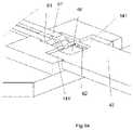
- FIGS. 9A-Cshow the interior of the slot 83 in which meter contacts corresponding to the contact pads of FIG. 3 are shown.
- meter contacts 91 and 91 ′bear on electrochemical test strip contact pad on connector 46 in the area between the connector tabs 141 and 141 ′ (on which electrochemical test strip contact pads are disposed).
- Meter contacts 92 and 92 ′make contact with the bottoms of electrochemical test strip connector tabs 141 and 141 ′ (on which surface the strip contact pads are disposed) and more clearly show in the views shown in FIGS. 9B and C.
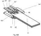
- FIGS. 10A-Cshow another embodiment of the invention in which there are corresponding aligned connector pins that can make contact with the strip when it is inserted in either orientation, up or down.
- FIG. 10Ashows a side-view where only meter contacts 91 and 92 are visible. In this illustration, each of the meter contact pins are in contact with their facing meter contact pin when a strip is not inserted; however, this is not a requirement.
- the meter contactsshould allow for a strip to be inserted, either by being spaced apart by an appropriate gap or by allowing for deflection and/or bending upon insertion of a strip, either of which is referred to herein as a “space” between the contacts.
- FIG. 10Ashows a side-view where only meter contacts 91 and 92 are visible. In this illustration, each of the meter contact pins are in contact with their facing meter contact pin when a strip is not inserted; however, this is not a requirement.
- the meter contactsshould allow for a strip
- FIG. 10Bshows a top view of the meter contacts when a strip is inserted and illustrates meter contacts 91 , 91 ′, 91 ′′, and 91 ′′′.
- FIG. 10Cshows a bottom view of the meter contacts when a strip is inserted and illustrates meter contacts 92 , 92 ′, 92 ′′, and 92 ′′′. Since each of these meter contacts can be addressed separately by the meter, it is possible for the meter to apply testing current or voltage to confirm the electrical continuity of the strip assuming the strip has an extended separation in the lead portion of the connector. Thus, in the example of FIGS. 10B and 10C , the meter would measure low resistance between meter contacts 91 ′ and 91 ′′ and between meter contacts 92 ′′′ and 92 when there is electrical continuity in the strip.
- the inventionalso provides a method for evaluating the electrical continuity of an electrochemical test strip for determination of an analyte in a sample prior to the application of that sample, comprising the steps of:
- test strip(a) inserting the test strip into a meter, wherein the test strip comprises:
- a first electrodea first connector comprising two contact pads, and a first conductive lead extending between the first electrode and the first connector to establish a path for conduction of an electrical signal between the first electrode and the first connector,
- a second electrodea second connector comprising one or more contact pads, and a second conductive lead extending between the second electrode and the second connector to establish a path for conduction of an electrical signal between the second electrode and the second connector, and
- a sample chamberfor receiving a sample, said first and second electrode being disposed to contact a sample within the sample chamber whereby an electrochemical signal is generated
- a further aspect of the inventionis a combination of a meter and a test strip in accordance with the invention.
Landscapes
- Life Sciences & Earth Sciences (AREA)
- Health & Medical Sciences (AREA)
- Chemical & Material Sciences (AREA)
- Physics & Mathematics (AREA)
- Biochemistry (AREA)
- Molecular Biology (AREA)
- Immunology (AREA)
- General Health & Medical Sciences (AREA)
- Analytical Chemistry (AREA)
- Engineering & Computer Science (AREA)
- Pathology (AREA)
- General Physics & Mathematics (AREA)
- Organic Chemistry (AREA)
- Chemical Kinetics & Catalysis (AREA)
- Electrochemistry (AREA)
- Biophysics (AREA)
- Wood Science & Technology (AREA)
- Zoology (AREA)
- Proteomics, Peptides & Aminoacids (AREA)
- Hematology (AREA)
- Biomedical Technology (AREA)
- Biotechnology (AREA)
- Bioinformatics & Cheminformatics (AREA)
- Genetics & Genomics (AREA)
- General Engineering & Computer Science (AREA)
- Microbiology (AREA)
- Urology & Nephrology (AREA)
- Medicinal Chemistry (AREA)
- Food Science & Technology (AREA)
- Investigating Or Analysing Biological Materials (AREA)
- Secondary Cells (AREA)
- Apparatus Associated With Microorganisms And Enzymes (AREA)
- Connection Of Batteries Or Terminals (AREA)
- Investigating Or Analyzing Materials By The Use Of Electric Means (AREA)
- Hybrid Cells (AREA)
- Battery Mounting, Suspending (AREA)
Abstract
Description
Claims (23)
Priority Applications (1)
| Application Number | Priority Date | Filing Date | Title |
|---|---|---|---|
| US10/908,662US7527716B2 (en) | 2004-05-21 | 2005-05-21 | Connector configuration for electrochemical cells and meters for use in combination therewith |
Applications Claiming Priority (2)
| Application Number | Priority Date | Filing Date | Title |
|---|---|---|---|
| US52155504P | 2004-05-21 | 2004-05-21 | |
| US10/908,662US7527716B2 (en) | 2004-05-21 | 2005-05-21 | Connector configuration for electrochemical cells and meters for use in combination therewith |
Publications (2)
| Publication Number | Publication Date |
|---|---|
| US20050258050A1 US20050258050A1 (en) | 2005-11-24 |
| US7527716B2true US7527716B2 (en) | 2009-05-05 |
Family
ID=34978606
Family Applications (8)
| Application Number | Title | Priority Date | Filing Date |
|---|---|---|---|
| US10/908,656Active2029-08-25US8268145B2 (en) | 2004-05-21 | 2005-05-20 | Electrochemical cell and method of making an electrochemical cell |
| US10/908,662Active2027-01-10US7527716B2 (en) | 2004-05-21 | 2005-05-21 | Connector configuration for electrochemical cells and meters for use in combination therewith |
| US10/908,664Active2028-09-27US8617365B2 (en) | 2004-05-21 | 2005-05-21 | Electrochemical assay device and related methods |
| US13/052,605Expired - LifetimeUS8182636B2 (en) | 2004-05-21 | 2011-03-21 | Electrochemical cell and method of making an electrochemical cell |
| US13/584,912AbandonedUS20120305396A1 (en) | 2004-05-21 | 2012-08-14 | Electrochemical Cell and Method of Making an Electrochemical Cell |
| US14/010,792Active2029-05-13US11175256B2 (en) | 2004-05-21 | 2013-08-27 | Electrochemical assay device and related methods |
| US14/291,990Expired - LifetimeUS9329150B2 (en) | 2004-05-21 | 2014-05-30 | Electrochemical cell and method of making an electrochemical cell |
| US15/144,024Expired - LifetimeUS10203298B2 (en) | 2004-05-21 | 2016-05-02 | Electrochemical cell and method of making an electrochemical cell |
Family Applications Before (1)
| Application Number | Title | Priority Date | Filing Date |
|---|---|---|---|
| US10/908,656Active2029-08-25US8268145B2 (en) | 2004-05-21 | 2005-05-20 | Electrochemical cell and method of making an electrochemical cell |
Family Applications After (6)
| Application Number | Title | Priority Date | Filing Date |
|---|---|---|---|
| US10/908,664Active2028-09-27US8617365B2 (en) | 2004-05-21 | 2005-05-21 | Electrochemical assay device and related methods |
| US13/052,605Expired - LifetimeUS8182636B2 (en) | 2004-05-21 | 2011-03-21 | Electrochemical cell and method of making an electrochemical cell |
| US13/584,912AbandonedUS20120305396A1 (en) | 2004-05-21 | 2012-08-14 | Electrochemical Cell and Method of Making an Electrochemical Cell |
| US14/010,792Active2029-05-13US11175256B2 (en) | 2004-05-21 | 2013-08-27 | Electrochemical assay device and related methods |
| US14/291,990Expired - LifetimeUS9329150B2 (en) | 2004-05-21 | 2014-05-30 | Electrochemical cell and method of making an electrochemical cell |
| US15/144,024Expired - LifetimeUS10203298B2 (en) | 2004-05-21 | 2016-05-02 | Electrochemical cell and method of making an electrochemical cell |
Country Status (13)
| Country | Link |
|---|---|
| US (8) | US8268145B2 (en) |
| EP (4) | EP1756557B1 (en) |
| JP (3) | JP5215661B2 (en) |
| KR (5) | KR101330785B1 (en) |
| CN (6) | CN103954668B (en) |
| AT (1) | ATE480636T1 (en) |
| AU (6) | AU2005246102B8 (en) |
| CA (3) | CA2566358C (en) |
| DE (1) | DE602005023435D1 (en) |
| ES (2) | ES2350489T3 (en) |
| NO (3) | NO20065934L (en) |
| PT (1) | PT1747281E (en) |
| WO (3) | WO2005114159A1 (en) |
Cited By (8)
| Publication number | Priority date | Publication date | Assignee | Title |
|---|---|---|---|---|
| US20050258035A1 (en)* | 2004-05-21 | 2005-11-24 | Agamatrix, Inc. | Electrochemical Cell and Method of Making an Electrochemical Cell |
| USD615884S1 (en)* | 2006-12-22 | 2010-05-18 | Abbott Diabetes Care Inc. | Sensor |
| US20100270149A1 (en)* | 2009-04-28 | 2010-10-28 | Abbott Diabetes Care Inc. | Smart Sensor Ports and Methods of Using Same |
| WO2012037486A1 (en) | 2010-09-17 | 2012-03-22 | Agamatrix, Inc. | Method and apparatus for encoding test strips |
| US20120075871A1 (en)* | 2010-09-27 | 2012-03-29 | Au Optronics Corporation | Assemblage structure for OLED lighting modules |
| EP2679156A1 (en) | 2012-06-28 | 2014-01-01 | Roche Diagniostics GmbH | Device for monitoring at least one body function of a user and method for manufacturing the same |
| US20140374278A1 (en)* | 2013-06-19 | 2014-12-25 | Cilag Gmbh International | Orientation independent meter |
| WO2018172349A1 (en) | 2017-03-21 | 2018-09-27 | Roche Diabetes Care Gmbh | Medical device and method for manufacturing a medical device |
Families Citing this family (116)
| Publication number | Priority date | Publication date | Assignee | Title |
|---|---|---|---|---|
| US6036924A (en) | 1997-12-04 | 2000-03-14 | Hewlett-Packard Company | Cassette of lancet cartridges for sampling blood |
| US6391005B1 (en) | 1998-03-30 | 2002-05-21 | Agilent Technologies, Inc. | Apparatus and method for penetration with shaft having a sensor for sensing penetration depth |
| US6616819B1 (en)* | 1999-11-04 | 2003-09-09 | Therasense, Inc. | Small volume in vitro analyte sensor and methods |
| US20060091006A1 (en)* | 1999-11-04 | 2006-05-04 | Yi Wang | Analyte sensor with insertion monitor, and methods |
| DE10057832C1 (en) | 2000-11-21 | 2002-02-21 | Hartmann Paul Ag | Blood analysis device has syringe mounted in casing, annular mounting carrying needles mounted behind test strip and being swiveled so that needle can be pushed through strip and aperture in casing to take blood sample |
| US8641644B2 (en) | 2000-11-21 | 2014-02-04 | Sanofi-Aventis Deutschland Gmbh | Blood testing apparatus having a rotatable cartridge with multiple lancing elements and testing means |
| US9427532B2 (en) | 2001-06-12 | 2016-08-30 | Sanofi-Aventis Deutschland Gmbh | Tissue penetration device |
| JP4209767B2 (en) | 2001-06-12 | 2009-01-14 | ペリカン テクノロジーズ インコーポレイテッド | Self-optimized cutting instrument with adaptive means for temporary changes in skin properties |
| AU2002344825A1 (en) | 2001-06-12 | 2002-12-23 | Pelikan Technologies, Inc. | Method and apparatus for improving success rate of blood yield from a fingerstick |
| US7749174B2 (en) | 2001-06-12 | 2010-07-06 | Pelikan Technologies, Inc. | Method and apparatus for lancet launching device intergrated onto a blood-sampling cartridge |
| US8337419B2 (en) | 2002-04-19 | 2012-12-25 | Sanofi-Aventis Deutschland Gmbh | Tissue penetration device |
| JP4272051B2 (en) | 2001-06-12 | 2009-06-03 | ペリカン テクノロジーズ インコーポレイテッド | Blood sampling apparatus and method |
| US7981056B2 (en) | 2002-04-19 | 2011-07-19 | Pelikan Technologies, Inc. | Methods and apparatus for lancet actuation |
| US7344507B2 (en) | 2002-04-19 | 2008-03-18 | Pelikan Technologies, Inc. | Method and apparatus for lancet actuation |
| US7041068B2 (en) | 2001-06-12 | 2006-05-09 | Pelikan Technologies, Inc. | Sampling module device and method |
| WO2002101359A2 (en) | 2001-06-12 | 2002-12-19 | Pelikan Technologies, Inc. | Integrated blood sampling analysis system with multi-use sampling module |
| US9795747B2 (en) | 2010-06-02 | 2017-10-24 | Sanofi-Aventis Deutschland Gmbh | Methods and apparatus for lancet actuation |
| EP1395185B1 (en) | 2001-06-12 | 2010-10-27 | Pelikan Technologies Inc. | Electric lancet actuator |
| US9226699B2 (en) | 2002-04-19 | 2016-01-05 | Sanofi-Aventis Deutschland Gmbh | Body fluid sampling module with a continuous compression tissue interface surface |
| US7344894B2 (en) | 2001-10-16 | 2008-03-18 | Agilent Technologies, Inc. | Thermal regulation of fluidic samples within a diagnostic cartridge |
| US8267870B2 (en) | 2002-04-19 | 2012-09-18 | Sanofi-Aventis Deutschland Gmbh | Method and apparatus for body fluid sampling with hybrid actuation |
| US9314194B2 (en) | 2002-04-19 | 2016-04-19 | Sanofi-Aventis Deutschland Gmbh | Tissue penetration device |
| US7648468B2 (en) | 2002-04-19 | 2010-01-19 | Pelikon Technologies, Inc. | Method and apparatus for penetrating tissue |
| US7491178B2 (en) | 2002-04-19 | 2009-02-17 | Pelikan Technologies, Inc. | Method and apparatus for penetrating tissue |
| US7331931B2 (en) | 2002-04-19 | 2008-02-19 | Pelikan Technologies, Inc. | Method and apparatus for penetrating tissue |
| US7297122B2 (en) | 2002-04-19 | 2007-11-20 | Pelikan Technologies, Inc. | Method and apparatus for penetrating tissue |
| US7909778B2 (en) | 2002-04-19 | 2011-03-22 | Pelikan Technologies, Inc. | Method and apparatus for penetrating tissue |
| US7708701B2 (en) | 2002-04-19 | 2010-05-04 | Pelikan Technologies, Inc. | Method and apparatus for a multi-use body fluid sampling device |
| US7582099B2 (en) | 2002-04-19 | 2009-09-01 | Pelikan Technologies, Inc | Method and apparatus for penetrating tissue |
| US7674232B2 (en) | 2002-04-19 | 2010-03-09 | Pelikan Technologies, Inc. | Method and apparatus for penetrating tissue |
| US9248267B2 (en) | 2002-04-19 | 2016-02-02 | Sanofi-Aventis Deustchland Gmbh | Tissue penetration device |
| US7524293B2 (en) | 2002-04-19 | 2009-04-28 | Pelikan Technologies, Inc. | Method and apparatus for penetrating tissue |
| US7547287B2 (en) | 2002-04-19 | 2009-06-16 | Pelikan Technologies, Inc. | Method and apparatus for penetrating tissue |
| US7410468B2 (en) | 2002-04-19 | 2008-08-12 | Pelikan Technologies, Inc. | Method and apparatus for penetrating tissue |
| US7371247B2 (en) | 2002-04-19 | 2008-05-13 | Pelikan Technologies, Inc | Method and apparatus for penetrating tissue |
| US7563232B2 (en) | 2002-04-19 | 2009-07-21 | Pelikan Technologies, Inc. | Method and apparatus for penetrating tissue |
| US7717863B2 (en) | 2002-04-19 | 2010-05-18 | Pelikan Technologies, Inc. | Method and apparatus for penetrating tissue |
| US9795334B2 (en) | 2002-04-19 | 2017-10-24 | Sanofi-Aventis Deutschland Gmbh | Method and apparatus for penetrating tissue |
| US8579831B2 (en) | 2002-04-19 | 2013-11-12 | Sanofi-Aventis Deutschland Gmbh | Method and apparatus for penetrating tissue |
| US8784335B2 (en) | 2002-04-19 | 2014-07-22 | Sanofi-Aventis Deutschland Gmbh | Body fluid sampling device with a capacitive sensor |
| US7901362B2 (en) | 2002-04-19 | 2011-03-08 | Pelikan Technologies, Inc. | Method and apparatus for penetrating tissue |
| US7481776B2 (en) | 2002-04-19 | 2009-01-27 | Pelikan Technologies, Inc. | Method and apparatus for penetrating tissue |
| US8221334B2 (en) | 2002-04-19 | 2012-07-17 | Sanofi-Aventis Deutschland Gmbh | Method and apparatus for penetrating tissue |
| US7976476B2 (en) | 2002-04-19 | 2011-07-12 | Pelikan Technologies, Inc. | Device and method for variable speed lancet |
| US7374544B2 (en) | 2002-04-19 | 2008-05-20 | Pelikan Technologies, Inc. | Method and apparatus for penetrating tissue |
| US7229458B2 (en) | 2002-04-19 | 2007-06-12 | Pelikan Technologies, Inc. | Method and apparatus for penetrating tissue |
| US7232451B2 (en) | 2002-04-19 | 2007-06-19 | Pelikan Technologies, Inc. | Method and apparatus for penetrating tissue |
| US7892183B2 (en) | 2002-04-19 | 2011-02-22 | Pelikan Technologies, Inc. | Method and apparatus for body fluid sampling and analyte sensing |
| US7141058B2 (en) | 2002-04-19 | 2006-11-28 | Pelikan Technologies, Inc. | Method and apparatus for a body fluid sampling device using illumination |
| US7291117B2 (en) | 2002-04-19 | 2007-11-06 | Pelikan Technologies, Inc. | Method and apparatus for penetrating tissue |
| US8702624B2 (en) | 2006-09-29 | 2014-04-22 | Sanofi-Aventis Deutschland Gmbh | Analyte measurement device with a single shot actuator |
| US8574895B2 (en) | 2002-12-30 | 2013-11-05 | Sanofi-Aventis Deutschland Gmbh | Method and apparatus using optical techniques to measure analyte levels |
| US7850621B2 (en) | 2003-06-06 | 2010-12-14 | Pelikan Technologies, Inc. | Method and apparatus for body fluid sampling and analyte sensing |
| WO2006001797A1 (en) | 2004-06-14 | 2006-01-05 | Pelikan Technologies, Inc. | Low pain penetrating |
| EP1635700B1 (en) | 2003-06-13 | 2016-03-09 | Sanofi-Aventis Deutschland GmbH | Apparatus for a point of care device |
| US8282576B2 (en) | 2003-09-29 | 2012-10-09 | Sanofi-Aventis Deutschland Gmbh | Method and apparatus for an improved sample capture device |
| EP1680014A4 (en) | 2003-10-14 | 2009-01-21 | Pelikan Technologies Inc | METHOD AND DEVICE FOR A VARIABLE USER INTERFACE |
| US8668656B2 (en) | 2003-12-31 | 2014-03-11 | Sanofi-Aventis Deutschland Gmbh | Method and apparatus for improving fluidic flow and sample capture |
| US7822454B1 (en) | 2005-01-03 | 2010-10-26 | Pelikan Technologies, Inc. | Fluid sampling device with improved analyte detecting member configuration |
| WO2006011062A2 (en) | 2004-05-20 | 2006-02-02 | Albatros Technologies Gmbh & Co. Kg | Printable hydrogel for biosensors |
| WO2005120365A1 (en) | 2004-06-03 | 2005-12-22 | Pelikan Technologies, Inc. | Method and apparatus for a fluid sampling device |
| US8652831B2 (en) | 2004-12-30 | 2014-02-18 | Sanofi-Aventis Deutschland Gmbh | Method and apparatus for analyte measurement test time |
| US7713392B2 (en) | 2005-04-15 | 2010-05-11 | Agamatrix, Inc. | Test strip coding and quality measurement |
| EP1797817A1 (en)* | 2005-12-19 | 2007-06-20 | F.Hoffmann-La Roche Ag | Sandwich sensor for determining the concentration of an analyte |
| DE502006004037D1 (en) | 2005-12-19 | 2009-07-30 | Roche Diagnostics Gmbh | SANDWICH SENSOR TO DETERMINE AN ANALYTIC CONCENTRATION |
| US20070196242A1 (en)* | 2006-02-23 | 2007-08-23 | Agamatrix, Inc. | Used test strip storage container |
| US8257651B2 (en)* | 2006-03-16 | 2012-09-04 | Agamatrix, Inc. | Analyte meter with rotatable user interface |
| US8057659B2 (en)* | 2006-06-27 | 2011-11-15 | Agamatrix, Inc. | Detection of analytes in a dual-mediator electrochemical test strip |
| US20080134806A1 (en)* | 2006-12-06 | 2008-06-12 | Agamatrix, Inc. | Container system for dispensing a liquid |
| US20080169799A1 (en)* | 2007-01-12 | 2008-07-17 | Shiow-Chen Wang | Method for biosensor analysis |
| CN101626720A (en) | 2007-01-23 | 2010-01-13 | 拜尔保健有限公司 | Analyte-testing device |
| EP2179027A4 (en)* | 2007-07-23 | 2013-12-04 | Agamatrix Inc | Electrochemical test strip |
| CN101779120B (en)* | 2007-07-26 | 2013-11-27 | 埃葛梅崔克斯股份有限公司 | Electrochemical test strips |
| EP2584044B1 (en) | 2007-07-26 | 2015-04-22 | Agamatrix, Inc. | Electrochemical analyte detections apparatus and method |
| US20090208816A1 (en)* | 2008-01-31 | 2009-08-20 | Viavattine Joseph J | Properly positioning stacked plate electrode for high volume assembly |
| EP2265324B1 (en) | 2008-04-11 | 2015-01-28 | Sanofi-Aventis Deutschland GmbH | Integrated analyte measurement system |
| US9123614B2 (en) | 2008-10-07 | 2015-09-01 | Mc10, Inc. | Methods and applications of non-planar imaging arrays |
| US8097926B2 (en) | 2008-10-07 | 2012-01-17 | Mc10, Inc. | Systems, methods, and devices having stretchable integrated circuitry for sensing and delivering therapy |
| US8389862B2 (en) | 2008-10-07 | 2013-03-05 | Mc10, Inc. | Extremely stretchable electronics |
| US9375169B2 (en) | 2009-01-30 | 2016-06-28 | Sanofi-Aventis Deutschland Gmbh | Cam drive for managing disposable penetrating member actions with a single motor and motor and control system |
| US8828330B2 (en)* | 2010-01-28 | 2014-09-09 | Abbott Diabetes Care Inc. | Universal test strip port |
| US8721850B2 (en)* | 2010-02-02 | 2014-05-13 | Roche Diagnostics Operations, Inc. | Biosensor and methods for manufacturing |
| US8965476B2 (en) | 2010-04-16 | 2015-02-24 | Sanofi-Aventis Deutschland Gmbh | Tissue penetration device |
| WO2012006210A2 (en) | 2010-07-07 | 2012-01-12 | Agamatrix, Inc. | Analyte test strip and analyte meter device |
| US10153483B2 (en) | 2011-06-23 | 2018-12-11 | Molecular Rebar Design, Llc | Lithium ion batteries using discrete carbon nanotubes, methods for production thereof and products obtained therefrom |
| KR20190026948A (en) | 2011-07-27 | 2019-03-13 | 아가매트릭스, 인코포레이티드 | Reagents for electrochemical test strips |
| US20130228475A1 (en)* | 2012-03-02 | 2013-09-05 | Cilag Gmbh International | Co-facial analytical test strip with stacked unidirectional contact pads and inert carrier substrate |
| US9217723B2 (en) | 2012-03-02 | 2015-12-22 | Cilag Gmbh International | Co-facial analytical test strip with stacked unidirectional contact pads |
| US9171794B2 (en) | 2012-10-09 | 2015-10-27 | Mc10, Inc. | Embedding thin chips in polymer |
| WO2014058473A1 (en) | 2012-10-09 | 2014-04-17 | Mc10, Inc. | Conformal electronics integrated with apparel |
| US9157882B2 (en) | 2012-12-20 | 2015-10-13 | Cilag Gmbh International | Analytical test strip |
| US9706647B2 (en) | 2013-05-14 | 2017-07-11 | Mc10, Inc. | Conformal electronics including nested serpentine interconnects |
| US20150047976A1 (en)* | 2013-08-16 | 2015-02-19 | Cilag Gmbh International | Analytical test strip having cantilevered contacts |
| TWM473191U (en)* | 2013-09-12 | 2014-03-01 | Jun-Tong Chen | Test strip for detection |
| US20150096906A1 (en)* | 2013-10-07 | 2015-04-09 | Cilag Gmbh International | Biosensor with bypass electrodes |
| US20150144507A1 (en)* | 2013-11-22 | 2015-05-28 | Cilag Gmbh International | Folded biosensor |
| EP3071096A4 (en) | 2013-11-22 | 2017-08-09 | Mc10, Inc. | Conformal sensor systems for sensing and analysis of cardiac activity |
| US9500616B2 (en)* | 2013-12-23 | 2016-11-22 | Cilag Gmbh International | Multi-orientation test strip |
| US10485118B2 (en) | 2014-03-04 | 2019-11-19 | Mc10, Inc. | Multi-part flexible encapsulation housing for electronic devices and methods of making the same |
| MX381317B (en)* | 2014-07-17 | 2025-03-12 | Siemens Healthcare Diagnostics Inc | SENSOR SET. |
| USD781270S1 (en) | 2014-10-15 | 2017-03-14 | Mc10, Inc. | Electronic device having antenna |
| WO2016134306A1 (en) | 2015-02-20 | 2016-08-25 | Mc10, Inc. | Automated detection and configuration of wearable devices based on on-body status, location, and/or orientation |
| US9788317B2 (en) | 2015-03-30 | 2017-10-10 | Intel IP Corporation | Access point (AP), user station (STA) and method for channel sounding using sounding trigger frames |
| CN104967995A (en)* | 2015-06-30 | 2015-10-07 | 北京奇虎科技有限公司 | A method, client and server for obtaining WIFI network password |
| US10709384B2 (en) | 2015-08-19 | 2020-07-14 | Mc10, Inc. | Wearable heat flux devices and methods of use |
| EP4079383A3 (en) | 2015-10-01 | 2023-02-22 | Medidata Solutions, Inc. | Method and system for interacting with a virtual environment |
| US10532211B2 (en) | 2015-10-05 | 2020-01-14 | Mc10, Inc. | Method and system for neuromodulation and stimulation |
| US10673280B2 (en) | 2016-02-22 | 2020-06-02 | Mc10, Inc. | System, device, and method for coupled hub and sensor node on-body acquisition of sensor information |
| US10277386B2 (en) | 2016-02-22 | 2019-04-30 | Mc10, Inc. | System, devices, and method for on-body data and power transmission |
| CN109310340A (en) | 2016-04-19 | 2019-02-05 | Mc10股份有限公司 | Method and system for measuring sweat |
| US10447347B2 (en) | 2016-08-12 | 2019-10-15 | Mc10, Inc. | Wireless charger and high speed data off-loader |
| IT201600126012A1 (en)* | 2016-12-14 | 2018-06-14 | Nanomaterials It S R L | Miniaturized electrochemical cell. |
| SE543921C2 (en)* | 2019-09-20 | 2021-09-21 | Rehninvent Ab | A device, a method, a system, and a kit of parts for measuring an amount of dirt |
| EP4355899A4 (en)* | 2021-08-05 | 2024-08-21 | Hewlett-Packard Development Company, L.P. | POLYMERASE CHAIN REACTION WELL COMPRISING A SIDEWALL WITH A FLUOROPOLYMER |
| WO2023014365A1 (en)* | 2021-08-05 | 2023-02-09 | Hewlett-Packard Development Company, L.P. | Polymerase chain reaction test well including resistive sheet |
| CN119555772B (en)* | 2025-01-24 | 2025-05-06 | 湖北工业大学 | Biomass electrochemical sensing probe, electrochemical sensor, preparation method and application |
Citations (20)
| Publication number | Priority date | Publication date | Assignee | Title |
|---|---|---|---|---|
| US4711245A (en) | 1983-05-05 | 1987-12-08 | Genetics International, Inc. | Sensor for components of a liquid mixture |
| US5282950A (en)* | 1991-07-15 | 1994-02-01 | Boehringer Mannheim Gmbh | Electrochemical analysis system |
| US5286362A (en) | 1990-02-03 | 1994-02-15 | Boehringer Mannheim Gmbh | Method and sensor electrode system for the electrochemical determination of an analyte or an oxidoreductase as well as the use of suitable compounds therefor |
| US5437999A (en) | 1994-02-22 | 1995-08-01 | Boehringer Mannheim Corporation | Electrochemical sensor |
| US5438271A (en)* | 1993-06-08 | 1995-08-01 | Boehringer Mannheim Corporation | Biosensing meter which detects proper electrode engagement and distinguishes sample and check strips |
| US5502396A (en)* | 1993-09-21 | 1996-03-26 | Asulab S.A. | Measuring device with connection for a removable sensor |
| US5520787A (en)* | 1994-02-09 | 1996-05-28 | Abbott Laboratories | Diagnostic flow cell device |
| US5985116A (en)* | 1996-12-24 | 1999-11-16 | Matsushita Electric Industrial Co., Ltd. | Biosensor |
| US6071391A (en)* | 1997-09-12 | 2000-06-06 | Nok Corporation | Enzyme electrode structure |
| WO2001033216A1 (en) | 1999-11-04 | 2001-05-10 | Therasense, Inc. | Small volume in vitro analyte sensor and related methods |
| US6349230B1 (en)* | 1998-02-26 | 2002-02-19 | Kyoto Daiichi Kagaku Co., Ltd. | Blood measuring instrument |
| US20030042150A1 (en) | 2000-03-22 | 2003-03-06 | Jun-Oh Ryu | Electrochemical biosensor test strip with recognition electrode and readout meter using this test strip |
| EP1304566A1 (en) | 2000-07-24 | 2003-04-23 | Matsushita Electric Industrial Co., Ltd. | Biosensor |
| US20030150724A1 (en)* | 1997-07-22 | 2003-08-14 | Kyoto Daiichi Kagaku Co., Ltd. | Concentration measuring apparatus, test strip for the concentration measuring apparatus biosensor system and method for forming terminal on the test strip |
| US20030201176A1 (en) | 2001-03-23 | 2003-10-30 | Kelly Mills | Method of making sensor |
| EP1382968A1 (en) | 2002-07-18 | 2004-01-21 | Matsushita Electric Industrial Co., Ltd. | Measuring apparatus with a biosensor |
| WO2005022143A2 (en) | 2003-08-21 | 2005-03-10 | Agamatrix, Inc. | Method and apparatus for assay of electrochemical properties |
| US20050069892A1 (en) | 2002-02-10 | 2005-03-31 | Iyengar Sridhar G. | Method and apparatus for assay of electrochemical properties |
| US20060037859A1 (en) | 2002-01-04 | 2006-02-23 | Lifescan, Inc. | Electrochemical cell connector |
| US20070017824A1 (en) | 2005-07-19 | 2007-01-25 | Rippeth John J | Biosensor and method of manufacture |
Family Cites Families (68)
| Publication number | Priority date | Publication date | Assignee | Title |
|---|---|---|---|---|
| WO1980000453A1 (en) | 1978-08-15 | 1980-03-20 | Nat Res Dev | Enzymatic processes |
| EP0078636B2 (en) | 1981-10-23 | 1997-04-02 | MediSense, Inc. | Sensor for components of a liquid mixture |
| DE3221339A1 (en) | 1982-06-05 | 1983-12-08 | Basf Ag, 6700 Ludwigshafen | METHOD FOR THE ELECTROCHEMICAL HYDRATION OF NICOTINAMIDADENINE-DINUCLEOTIDE |
| EP0170375B1 (en)* | 1984-06-13 | 1990-05-16 | Unilever Plc | Devices for use in chemical test procedures |
| DE68924026T3 (en)* | 1988-03-31 | 2008-01-10 | Matsushita Electric Industrial Co., Ltd., Kadoma | BIOSENSOR AND ITS MANUFACTURE. |
| US4942127A (en) | 1988-05-06 | 1990-07-17 | Molecular Devices Corporation | Polyredox couples in analyte determinations |
| FR2673289B1 (en) | 1991-02-21 | 1994-06-17 | Asulab Sa | SENSOR FOR MEASURING THE QUANTITY OF A COMPONENT IN SOLUTION. |
| US5264103A (en)* | 1991-10-18 | 1993-11-23 | Matsushita Electric Industrial Co., Ltd. | Biosensor and a method for measuring a concentration of a substrate in a sample |
| JP2658769B2 (en)* | 1991-10-21 | 1997-09-30 | 松下電器産業株式会社 | Biosensor |
| US5710011A (en) | 1992-06-05 | 1998-01-20 | Medisense, Inc. | Mediators to oxidoreductase enzymes |
| US5845702A (en)* | 1992-06-30 | 1998-12-08 | Heat Pipe Technology, Inc. | Serpentine heat pipe and dehumidification application in air conditioning systems |
| FR2699170B1 (en) | 1992-12-15 | 1995-07-28 | Asulab Sa | Complexes of a transition metal with 2,2'-bipyridine ligands substituted by at least one alkyl ammonium radical, their manufacturing process and their use as redox mediator. |
| US5589326A (en) | 1993-12-30 | 1996-12-31 | Boehringer Mannheim Corporation | Osmium-containing redox mediator |
| US5695947A (en)* | 1995-06-06 | 1997-12-09 | Biomedix, Inc. | Amperometric cholesterol biosensor |
| AUPN363995A0 (en) | 1995-06-19 | 1995-07-13 | Memtec Limited | Electrochemical cell |
| US6638415B1 (en)* | 1995-11-16 | 2003-10-28 | Lifescan, Inc. | Antioxidant sensor |
| US6174420B1 (en)* | 1996-11-15 | 2001-01-16 | Usf Filtration And Separations Group, Inc. | Electrochemical cell |
| AUPN661995A0 (en)* | 1995-11-16 | 1995-12-07 | Memtec America Corporation | Electrochemical cell 2 |
| JP3365184B2 (en) | 1996-01-10 | 2003-01-08 | 松下電器産業株式会社 | Biosensor |
| JP3913289B2 (en)* | 1996-06-14 | 2007-05-09 | セラセンス インコーポレーテッド | Glucose biosensor |
| AU6157898A (en)* | 1997-02-06 | 1998-08-26 | E. Heller & Company | Small volume (in vitro) analyte sensor |
| AUPO585797A0 (en)* | 1997-03-25 | 1997-04-24 | Memtec America Corporation | Improved electrochemical cell |
| GB9824627D0 (en) | 1998-11-11 | 1999-01-06 | Cambridge Sensors Ltd | Test strips for small volumes |
| JP3528529B2 (en)* | 1997-07-31 | 2004-05-17 | Nok株式会社 | Biosensor |
| US6129823A (en) | 1997-09-05 | 2000-10-10 | Abbott Laboratories | Low volume electrochemical sensor |
| US5876952A (en)* | 1997-12-08 | 1999-03-02 | Shieh; Paul | Non-invasive glucose biosensor: determination of glucose in urine |
| US6878251B2 (en)* | 1998-03-12 | 2005-04-12 | Lifescan, Inc. | Heated electrochemical cell |
| ATE221076T1 (en) | 1998-06-01 | 2002-08-15 | Roche Diagnostics Corp | REDOX-REVERSIBLE IMIDAZOLE-OSMIUM COMPLEX CONJUGATES |
| JP3874321B2 (en)* | 1998-06-11 | 2007-01-31 | 松下電器産業株式会社 | Biosensor |
| US6338790B1 (en) | 1998-10-08 | 2002-01-15 | Therasense, Inc. | Small volume in vitro analyte sensor with diffusible or non-leachable redox mediator |
| US6258229B1 (en)* | 1999-06-02 | 2001-07-10 | Handani Winarta | Disposable sub-microliter volume sensor and method of making |
| US6193873B1 (en) | 1999-06-15 | 2001-02-27 | Lifescan, Inc. | Sample detection to initiate timing of an electrochemical assay |
| JP2001021528A (en) | 1999-07-02 | 2001-01-26 | Akebono Brake Res & Dev Center Ltd | Electrode type biosensor |
| US7045054B1 (en)* | 1999-09-20 | 2006-05-16 | Roche Diagnostics Corporation | Small volume biosensor for continuous analyte monitoring |
| US6923894B2 (en) | 1999-11-11 | 2005-08-02 | Apex Biotechnology Corporation | Biosensor with multiple sampling ways |
| EP2151683A3 (en)* | 1999-11-15 | 2010-07-28 | Panasonic Corporation | Biosensor, thin film electrode forming method, quantification apparatus, and quantification method |
| EP1230248B1 (en) | 1999-11-15 | 2007-06-06 | Therasense, Inc. | Transition metal complexes attached to a polymer via a flexible chain |
| US6562210B1 (en)* | 1999-12-30 | 2003-05-13 | Roche Diagnostics Corporation | Cell for electrochemical anaylsis of a sample |
| KR100859280B1 (en) | 2000-03-28 | 2008-09-19 | 다이어베티스 다이어그노스틱스, 인크. | Meter with rapid response glucose sensor |
| DE60122517T2 (en)* | 2000-03-31 | 2007-03-08 | Lifescan, Inc., Milpitas | ELECTRICALLY CONDUCTIVE PATTERN FOR MONITORING THE FILLING OF MEDICAL DEVICES |
| US6488827B1 (en)* | 2000-03-31 | 2002-12-03 | Lifescan, Inc. | Capillary flow control in a medical diagnostic device |
| EP1167538A1 (en)* | 2000-06-30 | 2002-01-02 | Schibli Engineering GmbH | Biosensor and method for its production |
| KR20030038664A (en)* | 2000-07-14 | 2003-05-16 | 라이프스캔, 인코포레이티드 | Electrochemical method for measuring chemical reaction rates |
| US6726818B2 (en)* | 2000-07-21 | 2004-04-27 | I-Sens, Inc. | Biosensors with porous chromatographic membranes |
| US20020035188A1 (en)* | 2000-07-21 | 2002-03-21 | Steeghs Henricus Renier Gerardus | Agglomerating particulate materials |
| US6447657B1 (en)* | 2000-12-04 | 2002-09-10 | Roche Diagnostics Corporation | Biosensor |
| US6558528B1 (en)* | 2000-12-20 | 2003-05-06 | Lifescan, Inc. | Electrochemical test strip cards that include an integral dessicant |
| DE10117868A1 (en) | 2001-04-10 | 2002-10-17 | Lre Technology Partner Gmbh | Test strip, for the electrical measurement of substance concentrations in body fluid samples, has parallel outer layers with electrodes on their inner surfaces, and an absorbent intermediate layer with a specific reagent at the layers |
| US6855243B2 (en)* | 2001-04-27 | 2005-02-15 | Lifescan, Inc. | Electrochemical test strip having a plurality of reaction chambers and methods for using the same |
| JPWO2003042680A1 (en)* | 2001-11-14 | 2005-03-10 | 松下電器産業株式会社 | Biosensor |
| ATE479089T1 (en) | 2001-11-16 | 2010-09-15 | Stefan Ufer | FLEXIBLE SENSOR AND MANUFACTURING METHOD |
| US6749887B1 (en) | 2001-11-28 | 2004-06-15 | Lifescan, Inc. | Solution drying system |
| US6689411B2 (en) | 2001-11-28 | 2004-02-10 | Lifescan, Inc. | Solution striping system |
| KR100475634B1 (en)* | 2001-12-24 | 2005-03-15 | 주식회사 아이센스 | Biosensor equipped with sample introducing part which enables quick introduction of a small amount of sample |
| US6881578B2 (en)* | 2002-04-02 | 2005-04-19 | Lifescan, Inc. | Analyte concentration determination meters and methods of using the same |
| US6676101B2 (en)* | 2002-05-28 | 2004-01-13 | Minus K. Technology, Inc. | Vibration isolation system |
| US6732501B2 (en) | 2002-06-26 | 2004-05-11 | Heartware, Inc. | Ventricular connector |
| JP2004024764A (en) | 2002-06-28 | 2004-01-29 | Brother Ind Ltd | Sewing device, thread cassette of sewing device, and program of sewing device |
| EP1396717A1 (en)* | 2002-09-03 | 2004-03-10 | Matsushita Electric Industrial Co., Ltd. | Biosensor and measuring method using the same |
| US7291256B2 (en)* | 2002-09-12 | 2007-11-06 | Lifescan, Inc. | Mediator stabilized reagent compositions and methods for their use in electrochemical analyte detection assays |
| CN100451639C (en)* | 2002-10-25 | 2009-01-14 | 爱科来株式会社 | Analytical tool |
| CN1453579A (en)* | 2003-05-19 | 2003-11-05 | 浙江大学 | Electrochemical blood lactic acid sensor |
| US7387714B2 (en)* | 2003-11-06 | 2008-06-17 | 3M Innovative Properties Company | Electrochemical sensor strip |
| WO2005108968A1 (en) | 2004-05-12 | 2005-11-17 | Matsushita Electric Industrial Co., Ltd. | Biosensor, container for biosensor, and biosensor measuring apparatus |
| JP5215661B2 (en) | 2004-05-21 | 2013-06-19 | アガマトリックス インコーポレーテッド | Electrochemical cell and method for making an electrochemical cell |
| US7556723B2 (en) | 2004-06-18 | 2009-07-07 | Roche Diagnostics Operations, Inc. | Electrode design for biosensor |
| US7547382B2 (en) | 2005-04-15 | 2009-06-16 | Agamatrix, Inc. | Determination of partial fill in electrochemical strips |
| US9535027B2 (en)* | 2012-07-25 | 2017-01-03 | Abbott Diabetes Care Inc. | Analyte sensors and methods of using same |
- 2005
- 2005-05-20JPJP2007517568Apatent/JP5215661B2/ennot_activeExpired - Lifetime
- 2005-05-20CNCN201410219207.8Apatent/CN103954668B/ennot_activeExpired - Lifetime
- 2005-05-20WOPCT/IB2005/051657patent/WO2005114159A1/enactiveApplication Filing
- 2005-05-20CACA2566358Apatent/CA2566358C/ennot_activeExpired - Lifetime
- 2005-05-20EPEP05739481.9Apatent/EP1756557B1/ennot_activeExpired - Lifetime
- 2005-05-20AUAU2005246102Apatent/AU2005246102B8/ennot_activeExpired
- 2005-05-20CNCN200580024249.5Apatent/CN101014851B/ennot_activeExpired - Lifetime
- 2005-05-20CNCN201310269372.XApatent/CN103353475B/ennot_activeExpired - Lifetime
- 2005-05-20CNCN201210239381.XApatent/CN102778484B/ennot_activeExpired - Lifetime
- 2005-05-20EPEP16163412.6Apatent/EP3059580A1/ennot_activeWithdrawn
- 2005-05-20KRKR1020127034142Apatent/KR101330785B1/ennot_activeExpired - Fee Related
- 2005-05-20USUS10/908,656patent/US8268145B2/enactiveActive
- 2005-05-20KRKR1020137014837Apatent/KR101328608B1/ennot_activeExpired - Fee Related
- 2005-05-21KRKR1020067027006Apatent/KR20070026634A/ennot_activeWithdrawn
- 2005-05-21DEDE602005023435Tpatent/DE602005023435D1/ennot_activeExpired - Lifetime
- 2005-05-21KRKR1020067024297Apatent/KR101224499B1/ennot_activeExpired - Lifetime
- 2005-05-21ESES05740440Tpatent/ES2350489T3/ennot_activeExpired - Lifetime
- 2005-05-21JPJP2007517571Apatent/JP2008500551A/enactivePending
- 2005-05-21PTPT05740440Tpatent/PT1747281E/enunknown
- 2005-05-21USUS10/908,662patent/US7527716B2/enactiveActive
- 2005-05-21CNCNA2005800162607Apatent/CN1985001A/enactivePending
- 2005-05-21USUS10/908,664patent/US8617365B2/enactiveActive
- 2005-05-21AUAU2005245694Apatent/AU2005245694B2/ennot_activeExpired
- 2005-05-21CACA002565523Apatent/CA2565523A1/ennot_activeAbandoned
- 2005-05-21JPJP2007517570Apatent/JP2008500550A/enactivePending
- 2005-05-21CACA002566214Apatent/CA2566214A1/ennot_activeAbandoned
- 2005-05-21ATAT05740440Tpatent/ATE480636T1/enactive
- 2005-05-21AUAU2005248556Apatent/AU2005248556C1/ennot_activeExpired
- 2005-05-21WOPCT/IB2005/051659patent/WO2005113790A1/ennot_activeApplication Discontinuation
- 2005-05-21CNCNA2005800163239Apatent/CN1957249A/enactivePending
- 2005-05-21WOPCT/IB2005/051660patent/WO2005116622A1/enactiveApplication Filing
- 2005-05-21ESES05740441.0Tpatent/ES2569059T3/ennot_activeExpired - Lifetime
- 2005-05-21EPEP05740440Apatent/EP1747281B1/ennot_activeExpired - Lifetime
- 2005-05-21EPEP05740441.0Apatent/EP1747450B1/ennot_activeExpired - Lifetime
- 2006
- 2006-12-20NONO20065934Apatent/NO20065934L/enunknown
- 2006-12-20NONO20065935Apatent/NO20065935L/enunknown
- 2006-12-20NONO20065933Apatent/NO20065933L/enunknown
- 2006-12-21KRKR1020067027005Apatent/KR101265504B1/ennot_activeExpired - Lifetime
- 2010
- 2010-08-20AUAU2010212483Apatent/AU2010212483B2/ennot_activeExpired
- 2010-09-29AUAU2010224472Apatent/AU2010224472B2/ennot_activeExpired
- 2011
- 2011-03-21USUS13/052,605patent/US8182636B2/ennot_activeExpired - Lifetime
- 2012
- 2012-05-29AUAU2012203146Apatent/AU2012203146B2/ennot_activeExpired
- 2012-08-14USUS13/584,912patent/US20120305396A1/ennot_activeAbandoned
- 2013
- 2013-08-27USUS14/010,792patent/US11175256B2/enactiveActive
- 2014
- 2014-05-30USUS14/291,990patent/US9329150B2/ennot_activeExpired - Lifetime
- 2016
- 2016-05-02USUS15/144,024patent/US10203298B2/ennot_activeExpired - Lifetime
Patent Citations (22)
| Publication number | Priority date | Publication date | Assignee | Title |
|---|---|---|---|---|
| US4711245A (en) | 1983-05-05 | 1987-12-08 | Genetics International, Inc. | Sensor for components of a liquid mixture |
| US5286362A (en) | 1990-02-03 | 1994-02-15 | Boehringer Mannheim Gmbh | Method and sensor electrode system for the electrochemical determination of an analyte or an oxidoreductase as well as the use of suitable compounds therefor |
| US5282950A (en)* | 1991-07-15 | 1994-02-01 | Boehringer Mannheim Gmbh | Electrochemical analysis system |
| US5438271A (en)* | 1993-06-08 | 1995-08-01 | Boehringer Mannheim Corporation | Biosensing meter which detects proper electrode engagement and distinguishes sample and check strips |
| US5502396A (en)* | 1993-09-21 | 1996-03-26 | Asulab S.A. | Measuring device with connection for a removable sensor |
| US5520787A (en)* | 1994-02-09 | 1996-05-28 | Abbott Laboratories | Diagnostic flow cell device |
| US5437999A (en) | 1994-02-22 | 1995-08-01 | Boehringer Mannheim Corporation | Electrochemical sensor |
| US5985116A (en)* | 1996-12-24 | 1999-11-16 | Matsushita Electric Industrial Co., Ltd. | Biosensor |
| US20030150724A1 (en)* | 1997-07-22 | 2003-08-14 | Kyoto Daiichi Kagaku Co., Ltd. | Concentration measuring apparatus, test strip for the concentration measuring apparatus biosensor system and method for forming terminal on the test strip |
| US6503381B1 (en) | 1997-09-12 | 2003-01-07 | Therasense, Inc. | Biosensor |
| US6071391A (en)* | 1997-09-12 | 2000-06-06 | Nok Corporation | Enzyme electrode structure |
| US6349230B1 (en)* | 1998-02-26 | 2002-02-19 | Kyoto Daiichi Kagaku Co., Ltd. | Blood measuring instrument |
| WO2001033216A1 (en) | 1999-11-04 | 2001-05-10 | Therasense, Inc. | Small volume in vitro analyte sensor and related methods |
| US20030042150A1 (en) | 2000-03-22 | 2003-03-06 | Jun-Oh Ryu | Electrochemical biosensor test strip with recognition electrode and readout meter using this test strip |
| EP1304566A1 (en) | 2000-07-24 | 2003-04-23 | Matsushita Electric Industrial Co., Ltd. | Biosensor |
| US20030201176A1 (en) | 2001-03-23 | 2003-10-30 | Kelly Mills | Method of making sensor |
| US20060037859A1 (en) | 2002-01-04 | 2006-02-23 | Lifescan, Inc. | Electrochemical cell connector |
| US20050069892A1 (en) | 2002-02-10 | 2005-03-31 | Iyengar Sridhar G. | Method and apparatus for assay of electrochemical properties |
| EP1382968A1 (en) | 2002-07-18 | 2004-01-21 | Matsushita Electric Industrial Co., Ltd. | Measuring apparatus with a biosensor |
| US6969450B2 (en)* | 2002-07-18 | 2005-11-29 | Matsushita Electric Industrial Co., Ltd. | Biosensor and measuring apparatus for biosensor |
| WO2005022143A2 (en) | 2003-08-21 | 2005-03-10 | Agamatrix, Inc. | Method and apparatus for assay of electrochemical properties |
| US20070017824A1 (en) | 2005-07-19 | 2007-01-25 | Rippeth John J | Biosensor and method of manufacture |
Non-Patent Citations (1)
| Title |
|---|
| Morris N. A., Cardosi M. F., Birch B. J., Turner A. P. F., An electrochemical capillary fill device for the analysis of glucose incorporating glucose oxidase and ruthenium (III) hexamine as mediator, 1992, Electroanalysis, 4, 1-9.* |
Cited By (32)
| Publication number | Priority date | Publication date | Assignee | Title |
|---|---|---|---|---|
| US8268145B2 (en) | 2004-05-21 | 2012-09-18 | Agamatrix, Inc. | Electrochemical cell and method of making an electrochemical cell |
| US10203298B2 (en) | 2004-05-21 | 2019-02-12 | Agamatrix, Inc. | Electrochemical cell and method of making an electrochemical cell |
| US20050258035A1 (en)* | 2004-05-21 | 2005-11-24 | Agamatrix, Inc. | Electrochemical Cell and Method of Making an Electrochemical Cell |
| US9329150B2 (en) | 2004-05-21 | 2016-05-03 | Agamatrix, Inc. | Electrochemical cell and method of making an electrochemical cell |
| US9465005B2 (en) | 2006-12-22 | 2016-10-11 | Abbott Diabetes Care Inc. | Analyte sensors and methods of use |
| US8511147B2 (en) | 2006-12-22 | 2013-08-20 | Abbott Diabetes Care Inc. | Analyte sensors and methods of use |
| US9097660B2 (en) | 2006-12-22 | 2015-08-04 | Abbott Diabetes Care Inc. | Analyte sensors and methods of use |
| US8033162B2 (en) | 2006-12-22 | 2011-10-11 | Abbott Diabetes Care Inc. | Analyte sensors and methods of use |
| USD615884S1 (en)* | 2006-12-22 | 2010-05-18 | Abbott Diabetes Care Inc. | Sensor |
| US8753470B2 (en) | 2006-12-22 | 2014-06-17 | Abbott Diabetes Care Inc. | Analyte sensors and methods of use |
| US8771486B2 (en)* | 2009-04-28 | 2014-07-08 | Abbott Diabetes Care Inc. | Smart sensor ports and methods of using same |
| US9207201B2 (en)* | 2009-04-28 | 2015-12-08 | Abbott Diabetes Care Inc. | Smart sensor ports and methods of using same |
| US10058653B2 (en) | 2009-04-28 | 2018-08-28 | Abbott Diabetes Care Inc. | Smart sensor ports and methods of using same |
| US8758583B2 (en) | 2009-04-28 | 2014-06-24 | Abbott Diabetes Care Inc. | Smart sensor ports and methods of using same |
| US8764954B2 (en) | 2009-04-28 | 2014-07-01 | Abbott Diabetes Care Inc. | Smart sensor ports and methods of using same |
| US20100274181A1 (en)* | 2009-04-28 | 2010-10-28 | Abbott Diabetes Care Inc. | Smart sensor ports and methods of using same |
| US20140303592A1 (en)* | 2009-04-28 | 2014-10-09 | Abbott Diabetes Care Inc. | Smart Sensor Ports and Methods of Using Same |
| US9494546B2 (en) | 2009-04-28 | 2016-11-15 | Abbott Diabetes Care Inc. | Smart sensor ports and methods of using same |
| US20100270149A1 (en)* | 2009-04-28 | 2010-10-28 | Abbott Diabetes Care Inc. | Smart Sensor Ports and Methods of Using Same |
| US20100270150A1 (en)* | 2009-04-28 | 2010-10-28 | Abbott Diabetes Care Inc. | Smart Sensor Ports and Methods of Using Same |
| WO2012037486A1 (en) | 2010-09-17 | 2012-03-22 | Agamatrix, Inc. | Method and apparatus for encoding test strips |
| US9176091B2 (en)* | 2010-09-17 | 2015-11-03 | Agamatrix, Inc. | Method and apparatus for encoding test strips |
| US10488359B2 (en) | 2010-09-17 | 2019-11-26 | Agamatrix, Inc. | Method and apparatus for encoding test strips |
| US20130175184A1 (en)* | 2010-09-17 | 2013-07-11 | Agamatrix, Inc. | Method and Apparatus for Encoding Test Strips |
| US9046233B2 (en)* | 2010-09-27 | 2015-06-02 | Au Optronics Corporation | Assemblage structure for OLED lighting modules |
| US20120075871A1 (en)* | 2010-09-27 | 2012-03-29 | Au Optronics Corporation | Assemblage structure for OLED lighting modules |
| EP2679156A1 (en) | 2012-06-28 | 2014-01-01 | Roche Diagniostics GmbH | Device for monitoring at least one body function of a user and method for manufacturing the same |
| US10080497B2 (en) | 2012-06-28 | 2018-09-25 | Roche Diabetes Care, Inc. | Device for monitoring at least one body function of a user and method for manufacturing the same |
| US20140374278A1 (en)* | 2013-06-19 | 2014-12-25 | Cilag Gmbh International | Orientation independent meter |
| US9354194B2 (en)* | 2013-06-19 | 2016-05-31 | Cilag Gmbh International | Orientation independent meter |
| WO2018172349A1 (en) | 2017-03-21 | 2018-09-27 | Roche Diabetes Care Gmbh | Medical device and method for manufacturing a medical device |
| US10806387B2 (en) | 2017-03-21 | 2020-10-20 | Roche Diabetes Care, Inc. | Medical device and method for manufacturing a medical device |
Also Published As
Similar Documents
| Publication | Publication Date | Title |
|---|---|---|
| US7527716B2 (en) | Connector configuration for electrochemical cells and meters for use in combination therewith | |
| JP4885508B2 (en) | Small volume in vitro analyte sensor and related methods | |
| EP2308991B1 (en) | Multi-analyte test strip with inline working electrodes and shared opposing counter/reference electrode | |
| US9869653B2 (en) | Electrochemical sensors with carrier field | |
| EP2292785A1 (en) | Multi-analyte test strip with shared counter/reference electrode and inline electrode configuration | |
| US20110094896A1 (en) | Dual chamber, multi-analyte test strip with opposing electrodes | |
| WO2008134587A1 (en) | Test strip identification using conductive patterns | |
| US20070205114A1 (en) | Method of detecting biosensor filling | |
| KR20100042399A (en) | Electrochemical biosensor structure and measuring method using the same | |
| US8632664B2 (en) | Test meter for use with a dual chamber, multi-analyte test strip with opposing electrodes | |
| US20240060928A1 (en) | Biosensor | |
| TW201534915A (en) | Dual-chamber analytical test strip | |
| US20120312699A1 (en) | Differentiable analytical test strip and test meter combination | |
| EP2297574B1 (en) | Bio-sensor | |
| US20080169799A1 (en) | Method for biosensor analysis | |
| HK1106287A (en) | Connector configuration for electrochemical cells and meters for use in combination therewith | |
| HK1155493B (en) | Multi-analyte test strip with inline working electrodes and shared opposing counter/reference electrode |
Legal Events
| Date | Code | Title | Description |
|---|---|---|---|
| AS | Assignment | Owner name:AGAMATRIX, INC., MASSACHUSETTS Free format text:ASSIGNMENT OF ASSIGNORS INTEREST;ASSIGNOR:HARDING, IAN;REEL/FRAME:016169/0491 Effective date:20050610 | |
| STCF | Information on status: patent grant | Free format text:PATENTED CASE | |
| FPAY | Fee payment | Year of fee payment:4 | |
| FEPP | Fee payment procedure | Free format text:PAT HOLDER NO LONGER CLAIMS SMALL ENTITY STATUS, ENTITY STATUS SET TO UNDISCOUNTED (ORIGINAL EVENT CODE: STOL); ENTITY STATUS OF PATENT OWNER: LARGE ENTITY | |
| AS | Assignment | Owner name:MIDCAP FINANCIAL TRUST, MARYLAND Free format text:SECURITY INTEREST;ASSIGNOR:AGAMATRIX, INC.;REEL/FRAME:037405/0728 Effective date:20151223 | |
| FPAY | Fee payment | Year of fee payment:8 | |
| AS | Assignment | Owner name:PROSPECT CAPITAL CORPORATION, NEW YORK Free format text:PATENT SECURITY AGREEMENT;ASSIGNOR:AGAMATRIX, INC.;REEL/FRAME:044063/0828 Effective date:20170929 Owner name:AGAMATRIX, INC., NORTH CAROLINA Free format text:RELEASE BY SECURED PARTY;ASSIGNOR:MIDCAP FINANCIAL TRUST;REEL/FRAME:044034/0372 Effective date:20170929 | |
| AS | Assignment | Owner name:AGAMATRIX, INC., NEW HAMPSHIRE Free format text:CORRECTIVE ASSIGNMENT TO CORRECT THE ASSIGNEE ADDRESS PREVIOUSLY RECORDED AT REEL: 044034 FRAME: 0372. ASSIGNOR(S) HEREBY CONFIRMS THE RELEASE OF SECURITY INTEREST;ASSIGNOR:MIDCAP FINANCIAL TRUST;REEL/FRAME:044391/0941 Effective date:20170929 | |
| MAFP | Maintenance fee payment | Free format text:PAYMENT OF MAINTENANCE FEE, 12TH YEAR, LARGE ENTITY (ORIGINAL EVENT CODE: M1553); ENTITY STATUS OF PATENT OWNER: LARGE ENTITY Year of fee payment:12 | |
| AS | Assignment | Owner name:AGAMATRIX, INC., NEW HAMPSHIRE Free format text:RELEASE OF PATENT SECURITY AGREEMENT;ASSIGNOR:PROSPECT CAPITAL CORPORATION, AS COLLATERAL AGENT;REEL/FRAME:063604/0749 Effective date:20230505 |