US7527641B2 - Translational hinged door plate system - Google Patents
Translational hinged door plate systemDownload PDFInfo
- Publication number
- US7527641B2 US7527641B2US11/078,798US7879805AUS7527641B2US 7527641 B2US7527641 B2US 7527641B2US 7879805 AUS7879805 AUS 7879805AUS 7527641 B2US7527641 B2US 7527641B2
- Authority
- US
- United States
- Prior art keywords
- bone fastener
- fixation
- assembly
- retainer device
- closed position
- Prior art date
- Legal status (The legal status is an assumption and is not a legal conclusion. Google has not performed a legal analysis and makes no representation as to the accuracy of the status listed.)
- Expired - Lifetime, expires
Links
Images


Classifications
- A—HUMAN NECESSITIES
- A61—MEDICAL OR VETERINARY SCIENCE; HYGIENE
- A61B—DIAGNOSIS; SURGERY; IDENTIFICATION
- A61B17/00—Surgical instruments, devices or methods
- A61B17/56—Surgical instruments or methods for treatment of bones or joints; Devices specially adapted therefor
- A61B17/58—Surgical instruments or methods for treatment of bones or joints; Devices specially adapted therefor for osteosynthesis, e.g. bone plates, screws or setting implements
- A61B17/68—Internal fixation devices, including fasteners and spinal fixators, even if a part thereof projects from the skin
- A61B17/80—Cortical plates, i.e. bone plates; Instruments for holding or positioning cortical plates, or for compressing bones attached to cortical plates
- A61B17/8033—Cortical plates, i.e. bone plates; Instruments for holding or positioning cortical plates, or for compressing bones attached to cortical plates having indirect contact with screw heads, or having contact with screw heads maintained with the aid of additional components, e.g. nuts, wedges or head covers
- A61B17/8042—Cortical plates, i.e. bone plates; Instruments for holding or positioning cortical plates, or for compressing bones attached to cortical plates having indirect contact with screw heads, or having contact with screw heads maintained with the aid of additional components, e.g. nuts, wedges or head covers the additional component being a cover over the screw head
- A—HUMAN NECESSITIES
- A61—MEDICAL OR VETERINARY SCIENCE; HYGIENE
- A61B—DIAGNOSIS; SURGERY; IDENTIFICATION
- A61B17/00—Surgical instruments, devices or methods
- A61B17/56—Surgical instruments or methods for treatment of bones or joints; Devices specially adapted therefor
Definitions
- the present inventionis related to a fixation system. More particularly, the invention is related to a fixation system with a hinged cover plate covering at least a portion of a translational plate to prevent fastener back-out.
- Orthopedic fixation devicessuch as plates are frequently coupled to bone with fasteners inserted through plate holes. It is known that securing such fasteners to the bone plate, for example through the use of expansion-head screws, can decrease the incidence of loosening of the fixation assembly post-operatively. It is also known that a bushing may be disposed in each plate hole to receive the fastener to permit polyaxial movement so that the fastener may be angulated at a surgeon-selected angle. However, polyaxial movement of fasteners through set plate hole locations only increases attachment alternatives of the fasteners themselves. The plate holes remain fixed in relation to each other and to the longitudinal axis of the plate.
- a spinal fixation plateis applied to the anterior side of the affected vertebrae to span at least one affected disc space or vertebra (i.e. one in which at least a portion of the disc has been removed and a spinal fusion spacer has been inserted).
- the plateis fixed to the vertebrae using bone screws and acts to keep the vertebrae generally aligned during the initial period following fixation in which fusion of the spacer to the adjacent vertebrae occurs.
- the platealso acts to prevent the spacer from being expelled from the disc space during this initial period.
- a spinal fusion spaceris implanted between a pair of vertebrae to be fused, the spacer rests on the endplates of the vertebrae.
- the outer circumference of the end platescomprises hard cortical bone and thus provides a the best surface upon which to seat the spacer.
- the center portion of the endplatescomprises a thin cortical bone shell overlying a core of softer cancellous bone. Most, if not all, of the spacer contact surface, however, may be located in this center portion.
- the surgeontypically compresses the disc space by pressing the adjacent vertebrae together. This compression ensures a good engagement between the spacer the endplates, increasing the chances that fusion will occur. Often in the period immediately following surgery, the spacer will subside slightly either into the under-portion of the endplates or due to graft resorption (in the case of allograft spacers).
- this subsidencemay tend to shift more of the spinal load to the plate than is desirable.
- load shiftingcan also occur due to inaccuracies in installing the plate to the vertebrae. In extreme circumstances, this load shifting can result in non-fusion of the spacer to the vertebra, since firm compression between the spacer and the vertebrae is one factor contributing to successful fusion.
- fixation systemwhich provides the desired support to the vertebrae to be fused, and which allows limited translation of the vertebrae with respect to at least a portion of the plate, thereby limiting the undesirable effects of load shielding by the plate due to graft subsidence caused by settling or normal forces experienced in the spinal column. Promoting fusion of the adjacent vertebrae is thus accomplished.
- fasteners used with both rigid and translational plateshave a tendency to back-out of their installed positions under the influence of force and movements of the spine.
- the back-out of the fastenersis undesirable, as the fixation assembly may shift post-operatively to an undesired location, or loosen to an undesirable level.
- a fastener retaining devicecan be attached to a plate to block rearward movement of the fasteners relative to the plate after the fasteners have first been placed in their installed positions on the plate.
- An apparatus for use with a bone fastenerincludes a fixation device and a bone fastener retainer device.
- the fixation devicehas an opening configured to receive a bone fastener in an installed position in which an outer end portion of the bone fastener is located within the opening.
- the retainer deviceis receivable over the fixation device in a closed position extending over the location taken by the outer end portion of the bone fastener within the opening.
- the fixation device and the retainer devicetogether have first and second locking structures.
- the locking structuresare configured to engage each other in an undeflected condition when the retainer device is in a partially closed position, and to snap into interlocked engagement with each other under an applied force that moves the retainer device from the partially closed position to the closed position.
- the apparatusincludes a hinge supporting the retainer device for movement pivotally into the closed position, and a housing that encloses the outer end portions of the bone fasteners.
- the housingmay be defined by the fixation device and the retainer device, and may alternatively be defined by a structure that encloses the fixation device as well as the outer end portions of the bone fasteners.
- the housingmay further enclose and support a plurality of fixation devices for movement relative to each other.
- a fixation assembly for use with at least one bone fastenercomprising a fixation device having at least one opening configured to receive at least a portion of a bone fastener in an installed position, the at least one bone fastener having a head, wherein at least a portion of the head is located within the opening in an installed position; a bone fastener retainer device receivable over the fixation device in a closed position, wherein at least a portion of the bone fastener retainer device extends over at least a portion of the head when the fixation device is in a closed position; and wherein the fixation device further has a first locking structure, and the bone fastener retainer device further has a second locking structure, the locking structures configured to engage each other in an unlocked condition when the bone fastener retainer device is in a partially closed position, and configured to engage each other in a locked condition after an applied force shifts the bone fastener retainer device into a closed position.
- the first locking structuremay be a tab
- the second locking structuremay be a slot, and wherein the tab is receivable in the slot.
- the first and second locking structuresmay comprise edge portions of the fixation device and the bone fastener retainer device.
- the edge portionsmay be peripheral edge portions.
- the assemblymay further comprise a hinge connected to the fixation device and bone fastener retainer device, wherein the hinge may be configured to pivotally shift the bone fastener retainer device into a closed position.
- the fixation devicemay be a fixation plate with a plurality of bone fastener openings
- the bone fastener retainer devicemay be a cover plate configured to extend over at least a portion of the bone fastener openings in the fixation device when the bone fastener retainer device is in a closed position.
- the assemblymay further comprise at least one additional fixation device having an opening configured to receive a bone fastener in an installed position, wherein the bone fastener retainer device is configured to fit over the openings in the fixation devices when in a closed position.
- the assemblymay further comprise a base supporting the fixation devices for movement relative one another.
- the basemay include a ratchet device configured to define spaced-apart positions to which the fixation devices are movable relative to each other on the base.
- the base and the bone fastener retainer devicemay together be configured to define a housing that at least partially encloses the fixation devices when the bone fastener retainer device is in a closed position.
- At least one openingmay be substantially slot-shaped and has a longitudinal axis.
- a bone fastenermay be allowed to translate along the longitudinal axis of the opening, and may be allowed to translate in situ.
- a bone fastenermay be allowed to translate after it has been at least partially inserted into a bone segment.
- a bone fastenermay be allowed to translate when the bone fastener retainer device is in a closed position.
- At least one openingmay be substantially circular.
- the assemblymay further comprise a hinge connected to the fixation device, the hinge pivotally connected to a clamp.
- the clampmay be moveable between an open position and a closed position. At least a portion of the clamp may overlie at least a portion of the bone fastener retainer device when the clamp is in a closed position. At least a portion of the clamp may wrap around both the fixation device and the bone fastener retainer device when the clamp is in a closed position.
- a fixation assembly for use with a bone fastenercomprising a fixation device having at least one opening configured to receive at least a portion of a bone fastener in an installed position, the at least one bone fastener having a head, wherein at least a portion of the head is located within the opening in an installed position; a bone fastener retainer device receivable over the fixation device in a closed position, wherein at least a portion of the bone fastener retainer device extends over at least a portion of the head when the fixation device is in a closed position; and a first hinge connected to the fixation device and bone fastener retainer device, wherein the hinge is configured to pivotally shift the bone fastener retainer device into a closed position.
- the fixation devicemay be a fixation plate with a plurality of bone fastener openings
- the bone fastener retainer devicemay be a cover plate configured to extend over at least a portion of the bone fastener openings in the fixation device when the bone fastener retainer device is in a closed position.
- the assemblymay further comprising at least one additional fixation device having an opening configured to receive a bone fastener in an installed position, wherein the bone fastener retainer device is configured to fit over the openings in the fixation devices when in a closed position.
- the assemblymay further comprise a base supporting the fixation devices for movement relative one another.
- the basemay include a ratchet device configured to define spaced-apart positions to which the fixation devices are movable relative to each other on the base.
- the assemblymay further comprise a second hinge connected to the fixation device, the second hinge pivotally connected to a clamp.
- the clampis moveable between an open position and a closed position. At least a portion of the clamp may overlie at least a portion of the bone fastener retainer device when the clamp is in a closed position. At least a portion of the clamp may wrap around both the fixation device and the bone fastener retainer device when the clamp is in a closed position. At least a portion of the clamp may snap-fit around at least a portion bone fastener retainer device.
- the assemblymay further comprise first and second ends, wherein the first hinge is located near the first end, and the second hinge is located near the second end.
- a fixation assemblycomprising first and second fixation devices, each having a pair of openings for use with a bone fastener; first and second bone fastener retainer devices; wherein the first bone fastener retainer device is pivotally connected to the first fixation device; and wherein the first bone fastener retainer device is pivotable into a closed position for preventing bone fastener back-out.
- At least the first fixation devicemay have a lip, and the first bone fastener retainer device may be configured to engage the lip in a closed position.
- the first bone fastener retainer devicemay engage the lip in a snap-fit relationship.
- the second bone fastener retainer devicemay be pivotally connected to the second fixation device, and the second bone fastener retainer device may be pivotable into a closed position for preventing bone fastener back-out.
- the second fixation devicemay have a first and second lip, and wherein the second bone fastener retainer device may be configured to engage the lips in a closed position.
- the second bone fastener retainer devicemay engage at least one lip in a snap-fit relationship.
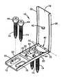
- FIG. 1is a perspective view of an embodiment of a one-level bone fixation assembly with a fastener retainer device in an open position.
- FIG. 2is a perspective view of the embodiment of FIG. 1 with fasteners.
- FIG. 3is a perspective view of the embodiment of FIGS. 1-2 with the fastener retainer device in a closed position.
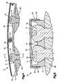
- FIG. 4is a cross-sectional view of the assembly of FIG. 3 taken along the line A-A, showing a pair of fasteners in adjacent vertebrae.
- FIG. 5is a partial cross-sectional view of the assembly of FIG. 4 taken on the line C-C.
- FIG. 6is a partial cross-sectional view of the assembly of FIG. 3 taken along the line B-B, just before the moment where the locking tab is fully inserted into the slot.
- FIG. 7is a partial cross-sectional view of the assembly of FIG. 3 taken along the line B-B, after the locking tab is fully inserted into the slot.
- FIG. 8is a perspective view of a second embodiment of a one-level bone fixation assembly with a fastener retainer device in a closed, unlocked position.
- FIG. 9is a perspective view of the assembly of FIG. 8 with a fastener retainer device in a closed, locked position.
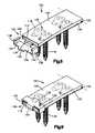
- FIG. 10is a perspective view of a third embodiment of a one-level bone fixation assembly with two fastener retainer devices in an open position.
- FIG. 11is a partial cross-sectional view of the assembly of FIG. 10 with fasteners taken transversely across the assembly, with a fastener retainer device in a partially closed position, showing a pair of fasteners in a single vertebrae.
- FIG. 12is a view showing the assembly of FIG. 11 with a fastener retainer device in a fully closed position.
- FIG. 13is a partial cross-sectional view of a fourth embodiment of a one-level bone fixation assembly having an non-hinged fastener retainer device similar to those shown in FIGS. 10-12 , lockable by a depressive force.
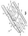
- FIG. 14is a perspective view of a fifth embodiment of a one-level bone fixation assembly with a fastener retainer device in an open position.
- the plates described hereinmay be used in spinal fusion procedures in which a damaged or diseased disc (or part of a disc) is removed from between a pair of vertebrae and a spinal fusion spacer is placed between the vertebrae.
- the platesmay be applied to an anterior portion of the affected vertebrae to span the affected disc space, and may be fixed to the vertebrae using bone screws.
- the platemay function to maintain the vertebrae aligned during the initial period following fixation in which fusion of the spacer to the adjacent vertebrae occurs.
- the platemay also function to share some of the axial spinal load applied to the fusion spacer to prevent extreme subsidence of the spacer into the vertebral body, such as where the patient has poor bone quality.
- the platesmay also act to prevent the spacer from being expelled from the disc space during the initial post-operative period.
- the platesmay be used for single level (i.e. one-disc) or multiple-level (i.e. multiple disc) fusion procedures. Some embodiments may be used for corpectomy procedures, in which at least a portion of a vertebral body is removed.
- Single level platesgenerally may have two pairs of bone screw holes, while the multi-level plates generally may have three or more pairs of holes.
- FIGS. 1-3show an embodiment of a one-level fixation assembly 10 .
- assembly 10includes a bone fixation plate 12 which, in this particular example, is a spinal fixation plate.
- a plurality of fasteners 14may be receivable through openings 15 in the fixation plate 12 to fasten it to the spine, as shown in FIG. 2 .
- a fastener retainer device 16may cooperate with the fixation plate 12 .
- the fastener retainer device 16is a cover plate that fits over the fixation plate 12 in a closed position, as shown in FIG. 3 . When the fasteners 14 are installed to fasten the fixation plate 12 to the spine, the cover plate 16 can be placed in the closed position to block the fasteners 14 from backing out of their installed positions relative to the fixation plate 12 .
- the fixation plate 12may be configured to overlie a section of the spine to provide support that maintains the alignment of two or more vertebrae in that section of the spine. Accordingly, the fixation plate 12 may be elongated to extend between at least one pair of vertebrae.
- the openings 15may be arranged in pairs adjacent to the opposite ends of the fixation plate 12 so that the pair of fasteners 14 at one pair of openings 15 can fasten the fixation plate 12 to a first vertebra and the pair of fasteners 14 at the other pair of openings 15 can fasten the fixation plate 12 to a second vertebra. Additionally, the openings 15 in each pair may be shaped as slots that are elongated lengthwise of the fixation plate 12 .
- Slots 15may also be fitted with captive clips (not shown) to allow fasteners 14 to move within the slots 15 and further prevent fastener 14 back-out, the details, materials, and methods of which are described in U.S. patent application Ser. No. 10/653,164 entitled “Bone Plate with Captive Clips”, by Duong, et al., filed Sep. 3, 2003, the entire disclosure of which application is expressly incorporated by reference herein.
- a pair of side flanges 20may extend along the length of the fixation plate 12 between its opposite ends.
- a closure block 22may be mounted on the fixation plate 12 midway between the opposite ends, and may have a slot 25 .
- the cover plate 16may also be elongated with a pair of side flanges 30 extending fully along its length. Moreover, the cover plate 16 may be slightly wider than the fixation plate 12 so as to fit over the fixation plate 12 , as shown in FIG. 3 , with the side flanges 20 on the fixation plate 12 able to be received between the side flanges 30 on the cover plate 16 .
- a hinge 40may support the cover plate 16 on the fixation plate 12 for movement pivotally between the open position of FIGS. 1-2 and the closed position of FIG. 3 .
- FIGS. 4-5show cross-sectional views of the embodiment of FIG. 3 , with the assembly 10 fastened to adjacent vertebrae 60 and 62 .
- a locking tab 42 on the cover plate 16may then be received in the slot 25 on the fixation plate 12 such that the cover plate 16 snaps into interlocked engagement with the fixation plate 12 .
- the cover plate 16then may extend over the outer end portions 44 of the bone screws 14 to block the bone screws 14 from backing out of the installed positions in which they fasten the fixation plate 12 to the vertebrae 60 and 62 .
- FIGS. 6-7are cross-sectional views of the assembly of FIG. 3 taken along the line B-B.
- FIG. 6shows the locking tab 42 just before it fully enters the slot 25
- FIG. 7shows the locking tab 42 after it has fully entered the slot 25 .
- the interlock between the cover plate 16 and the retainer plate 12can be established merely by applying a force F that presses the top side of the cover plate 16 downward, as indicated schematically in FIG. 3 , to push the locking tab 42 downward into the slot 25 . This may cause the locking tab 42 to snap into interlocked engagement with the closure block 22 . More specifically, the cover plate 16 may first be placed in a partially closed position, as shown in FIG. 6 , with the locking tab 42 resting on the closure block 22 . The applied force F may then cause the locking tab 42 to deflect the closure block 22 so that the edge of the locking tab 42 slides downward and snaps beneath the edges of the slot 25 to lock the cover plate 16 in the closed position, as shown in FIG. 7 .
- FIGS. 8-9show a second embodiment of a one-level bone fixation assembly 100 .
- the fixation assembly 100 in this embodimentincludes a bone fixation plate 112 with slots 115 configured to receive fasteners 116 in installed positions in which the outer end portions 118 of the fasteners 116 are located within the slots 115 .
- the fixation assembly 100may further include a fastener retainer device in the form of a cover plate 120 which, like the cover plate 16 described above, may be supported by a hinge 122 for movement pivotally into a closed position on the fixation plate 112 . When the cover plate 120 is in the closed position, as shown in FIG.
- the assembly 100differs from the previously recited assembly 10 by including a locking device 130 as a substitute for the closure block 22 and locking tab 42 described above.
- the locking device 130may include a clamp 132 and a hinge 134 .
- the hinge 134may support the clamp 132 on the fixation plate 112 for movement pivotally into the locking position, as shown in FIG. 9 .
- a major portion 136 of the clamp 132may extend across the adjacent end portion of the cover plate 120 .
- a pair of arms 138 at opposite ends of the major portion 136may also extend downward past the side flanges 140 on the cover plate 120 , and a pair of barbs 142 may project from the arms 138 beneath the fixation plate 112 to hold the clamp 132 in the locking position.
- the clamp 132then may hold the closure plate 120 in the closed position.
- the clamp 132should be flexible enough for the barbs 142 to spread apart and slide downward beside the flanges 140 on the cover plate 120 , and to snap back toward each other beneath the fixation plate 112 as the clamp 132 is moved pivotally into the locking position.
- FIGS. 10-12show a third embodiment of a one-level bone fixation assembly 200 .
- assembly 200includes a pair of bone fixation plates 210 and 212 .
- the fixation plates 210 and 212may be joined by a connector 214 to define a single spinal fixation plate 216 with two pairs of fastener slots 217 and 219 .
- Two fastener retainer devices 220 and 222may be mounted on the fixation devices 210 and 212 by hinges 224 and 226 , respectively, that may support them for movement pivotally into closed positions.
- the retainer device 220may be a cover plate with an arcuate peripheral edge portion 230 that may snap into interlocked engagement with a lip 232 at the peripheral edge of the fixation device 210 . This may occur upon pivotal movement of the retainer device 220 from the partially closed position of FIG. 11 to the closed position of FIG. 12 under an applied force F. When the retainer device 220 is in the closed position, it may extend over fastener heads 234 in the slots 217 to block them from backing out of their installed positions on the fixation device 210 .
- FIG. 13is a fourth embodiment of a one-level bone fixation assembly 300 similar to the assembly 200 of FIGS. 10-12 .
- the fastener retainer device 302 in this assembly 300may have two arcuate peripheral edge portions 306 , whereas the fastener retainer device 220 described above in connection with FIGS. 10-12 has a hinge 224 and a single arcuate peripheral edge portion 230 .
- the assembly 300may further include a bone fixation plate 310 with two corresponding lips 312 , each of which may be substantially the same as the single lip 232 of FIGS. 10-11 .
- the retainer device 302 of FIG. 13can be snapped into interlocked engagement with the fixation plate 310 in at least two different ways.
- An edge portion 306 at one side of the device 302can first be hooked over the corresponding lip 312 , and the other edge portion 306 can then be snapped pivotally over its corresponding lip 312 , similar to the manner described above with reference to FIGS. 11-12 .
- the retainer device 302can first be placed on the fixation device 310 in a partially closed position in which the edge portions 306 rest on the lips 312 , as shown in phantom view in FIG. 13 .
- the edge portions 306can then be snapped into closed positions simultaneously, as shown in full in FIG. 13 , under the influence of an applied force F at the top side of the retainer device 302 .
- FIG. 14is a fifth embodiment of a one-level bone fixation assembly 410 .
- the housing 400 of FIG. 14may include a base 412 and a cover 414 .
- a hinge 416may support the cover 414 on the base 412 .
- the base 412is a box-shaped structure with a rectangular bottom wall 420 .
- a pair of slots 421may extend along the length of the bottom wall 420 .
- the base 412further may have a pair of opposite side walls 422 that together define a track with opposed ratchet teeth 424 .
- a pair of fixation blocks 430may be supported on the side walls 424 of the base 412 for movement between spaced-apart positions defined by the ratchet teeth 424 .
- Each fixation block 430may have a pair of openings 431 configured to receive fasteners (not shown) in installed positions in which outer end portions of the fasteners may be located within the openings 431 .
- the fastenersmay be receivable in the fixation blocks 430 in installed positions in which their heads may rest in the openings 431 and their screw-threaded stems may project into vertebrae through the slots 421 in the bottom wall 420 .
- the bottom wall 420may serve as a fixation plate in cooperation with the two movable fixation blocks 430 .
- the slots 421 and the ratchet teeth 424may permit the pairs of fasteners at the fixation blocks 430 to shift in relation to a corresponding pair of vertebrae to which the fixation blocks 430 are fastened by the fasteners.
- a closure block 440may be mounted on the base 412 .
- a locking tab 442 on the cover 414may snap into a slot 445 in the closure block 440 upon pivotal movement of the cover 414 from the open position shown in FIG. 14 to a closed position (not shown) in which it may be received over the base 412 . This may be accomplished with an applied force in the same manner described above with reference to FIGS. 6-7 .
- the cover 414then may extend over the fastener heads on the fixation blocks 430 to serve as a retainer device that blocks the bone screws from backing out of their installed positions on the fixation devices 430 .
- fixation plates and other fixation assembly componentsmay be varied to fit the anatomy of a given patient, depending at least in part on the size of the vertebra the plates will be attached to, and the size of the intervertebral space to be spanned.
- Fixation assembliesmay also be substantially flat, to reduce the overall profile of the assemblies.
- each of the above described fixation assembliesmay exhibit some or all of the suitable characteristics of each of the embodiments described herein. For instance, although not shown in a figure, it may be preferable to utilize the snap-down fastener retention device design of FIG. 13 with the box-shaped fixation assembly 410 of FIG. 14 .
- each of the above described fixation assembliesmay be assembled in a multi-level arrangement to span more than one intervertebral disc space. It is also contemplated that each of the above described assemblies may be assembled in corpectomy model, to span the length of at least one removed vertebral body. Variations or combinations of these alternatives is also contemplated.
- Each of the fasteners, fixation plates, fastener retainers, and other components disclosed hereinmay be formed of a titanium alloy such as titanium-aluminum-niobium, which may be anodized.
- a titanium alloysuch as titanium-aluminum-niobium, which may be anodized.
- One material for use with each of the plates and screws described hereinis Ti-6Al-7Nb, with a density of about 4.52 gm/cc, a modulus of elasticity of about 105 GPa, an ultimate tensile strength of about 900 MPa, and a yield strength of about 800 MPa.
- Surfaces of the fastenersmay also be burr free, with all sharp edges broken to a maximum of 0.1 mm.
Landscapes
- Health & Medical Sciences (AREA)
- Orthopedic Medicine & Surgery (AREA)
- Surgery (AREA)
- Life Sciences & Earth Sciences (AREA)
- Heart & Thoracic Surgery (AREA)
- Veterinary Medicine (AREA)
- Engineering & Computer Science (AREA)
- Biomedical Technology (AREA)
- Nuclear Medicine, Radiotherapy & Molecular Imaging (AREA)
- Medical Informatics (AREA)
- Molecular Biology (AREA)
- Animal Behavior & Ethology (AREA)
- General Health & Medical Sciences (AREA)
- Public Health (AREA)
- Neurology (AREA)
- Prostheses (AREA)
- Surgical Instruments (AREA)
- Hinges (AREA)
Abstract
Description
Claims (18)
Priority Applications (12)
| Application Number | Priority Date | Filing Date | Title |
|---|---|---|---|
| US11/078,798US7527641B2 (en) | 2005-03-11 | 2005-03-11 | Translational hinged door plate system |
| BRPI0608999ABRPI0608999A2 (en) | 2005-03-11 | 2006-03-03 | fastening set |
| AU2006223599AAU2006223599A1 (en) | 2005-03-11 | 2006-03-03 | Translational hinged door plate system |
| CA002600806ACA2600806A1 (en) | 2005-03-11 | 2006-03-03 | Translational hinged door plate system |
| NZ561398ANZ561398A (en) | 2005-03-11 | 2006-03-03 | Prevention of fastener back-out by using a hinged door plate system on a bone fixation device |
| PCT/US2006/007660WO2006098907A2 (en) | 2005-03-11 | 2006-03-03 | Translational hinged door plate system |
| JP2008500776AJP2008537687A (en) | 2005-03-11 | 2006-03-03 | Translational hinge door plate system |
| CN2006800153513ACN101370439B (en) | 2005-03-11 | 2006-03-03 | Hinged door type moving plate system |
| EP06736905AEP1871255A2 (en) | 2005-03-11 | 2006-03-03 | Translational hinged door plate system |
| KR1020077022319AKR20070118613A (en) | 2005-03-11 | 2006-03-03 | Moving hinged door plate system |
| TW095108245ATWI330072B (en) | 2005-03-11 | 2006-03-10 | Fixation assembly for use with at least one bone fastener |
| CO07103471ACO6190592A2 (en) | 2005-03-11 | 2007-10-03 | PLATE SYSTEM WITH DOUBLE DOOR |
Applications Claiming Priority (1)
| Application Number | Priority Date | Filing Date | Title |
|---|---|---|---|
| US11/078,798US7527641B2 (en) | 2005-03-11 | 2005-03-11 | Translational hinged door plate system |
Publications (2)
| Publication Number | Publication Date |
|---|---|
| US20060217721A1 US20060217721A1 (en) | 2006-09-28 |
| US7527641B2true US7527641B2 (en) | 2009-05-05 |
Family
ID=36572361
Family Applications (1)
| Application Number | Title | Priority Date | Filing Date |
|---|---|---|---|
| US11/078,798Expired - LifetimeUS7527641B2 (en) | 2005-03-11 | 2005-03-11 | Translational hinged door plate system |
Country Status (12)
| Country | Link |
|---|---|
| US (1) | US7527641B2 (en) |
| EP (1) | EP1871255A2 (en) |
| JP (1) | JP2008537687A (en) |
| KR (1) | KR20070118613A (en) |
| CN (1) | CN101370439B (en) |
| AU (1) | AU2006223599A1 (en) |
| BR (1) | BRPI0608999A2 (en) |
| CA (1) | CA2600806A1 (en) |
| CO (1) | CO6190592A2 (en) |
| NZ (1) | NZ561398A (en) |
| TW (1) | TWI330072B (en) |
| WO (1) | WO2006098907A2 (en) |
Cited By (27)
| Publication number | Priority date | Publication date | Assignee | Title |
|---|---|---|---|---|
| US20060276794A1 (en)* | 2005-05-12 | 2006-12-07 | Stern Joseph D | Revisable anterior cervical plating system |
| US20060293670A1 (en)* | 2005-06-03 | 2006-12-28 | Smisson Hugh F Iii | Surgical stabilization system |
| US20070173840A1 (en)* | 2006-01-11 | 2007-07-26 | Huebner Randall J | Bone plate with cover |
| US20090076555A1 (en)* | 2007-09-13 | 2009-03-19 | David Lowry | Transcorporeal spinal decompression and repair system and related method |
| US20090264886A1 (en)* | 2005-05-12 | 2009-10-22 | Stern Joseph D | Distraction device for use with a revisable anterior cervical plating system |
| US20100057134A1 (en)* | 2007-08-07 | 2010-03-04 | David Lowry | Implantable bone plate system and related method for spinal repair |
| US20100057086A1 (en)* | 2008-08-29 | 2010-03-04 | Zimmer, Inc. | Anodized locking plate components |
| US20100152784A1 (en)* | 2007-08-07 | 2010-06-17 | David Lowry | Implantable vertebral frame systems and related methods for spinal repair |
| US20100152793A1 (en)* | 2007-09-13 | 2010-06-17 | David Lowry | Transcorporeal spinal decompression and repair systems and related methods |
| US20110288590A1 (en)* | 2010-05-19 | 2011-11-24 | O'farrell Desmond | Implantable vertebral frame systems and related methods for spinal repair |
| US20120143199A1 (en)* | 2009-08-06 | 2012-06-07 | Depuy (Ireland) | Surgical instrument and system of surgical instruments |
| US20120158057A1 (en)* | 2008-09-04 | 2012-06-21 | Dennis Bullard | Anterior cervical instrumentation systems, methods and devices |
| US20120217362A1 (en)* | 2011-02-28 | 2012-08-30 | Umbra Llc | Drapery rod bracket and cover plate |
| US20130073044A1 (en)* | 2011-09-16 | 2013-03-21 | Thomas Gamache | Removable, bone-securing cover plate for intervertebral fusion cage |
| US20130253516A1 (en)* | 2012-03-23 | 2013-09-26 | John L Mackall | Occipital plate |
| US9107704B2 (en) | 2008-09-04 | 2015-08-18 | Bullard Spine, Llc | Anterior cervical instrumentation systems, methods and devices |
| US9526620B2 (en) | 2009-03-30 | 2016-12-27 | DePuy Synthes Products, Inc. | Zero profile spinal fusion cage |
| USD779065S1 (en) | 2014-10-08 | 2017-02-14 | Nuvasive, Inc. | Anterior cervical bone plate |
| US9662225B2 (en) | 2012-03-06 | 2017-05-30 | DePuy Synthes Products, Inc. | Nubbed plate |
| US9687354B2 (en) | 2008-03-26 | 2017-06-27 | DePuy Synthes Products, Inc. | Posterior intervertebral disc inserter and expansion techniques |
| US10182921B2 (en) | 2012-11-09 | 2019-01-22 | DePuy Synthes Products, Inc. | Interbody device with opening to allow packing graft and other biologics |
| US10206787B2 (en) | 2006-12-22 | 2019-02-19 | Medos International Sarl | Composite vertebral spacers and instrument |
| US10335289B2 (en) | 2010-09-23 | 2019-07-02 | DePuy Synthes Products, Inc. | Stand alone intervertebral fusion device |
| US10369015B2 (en) | 2010-09-23 | 2019-08-06 | DePuy Synthes Products, Inc. | Implant inserter having a laterally-extending dovetail engagement feature |
| US10500062B2 (en) | 2009-12-10 | 2019-12-10 | DePuy Synthes Products, Inc. | Bellows-like expandable interbody fusion cage |
| US10940016B2 (en) | 2017-07-05 | 2021-03-09 | Medos International Sarl | Expandable intervertebral fusion cage |
| US11529241B2 (en) | 2010-09-23 | 2022-12-20 | DePuy Synthes Products, Inc. | Fusion cage with in-line single piece fixation |
Families Citing this family (13)
| Publication number | Priority date | Publication date | Assignee | Title |
|---|---|---|---|---|
| US8551144B2 (en)* | 2008-04-22 | 2013-10-08 | Collab Comlo, LLC | Bone plate system configurable as static or dynamic implant |
| CA2761733C (en) | 2009-06-01 | 2019-01-08 | Her Majesty The Queen In Right Of Canada As Represented By The Minister Of Health | Reagents and methods for detecting influenza virus proteins |
| CA2899167C (en)* | 2013-01-25 | 2021-08-31 | DePuy Synthes Products, Inc. | Caps for implants, implant assemblies, and methods of use |
| KR101599603B1 (en) | 2013-08-26 | 2016-03-03 | 경북대학교 산학협력단 | Medical inserting apparatus |
| KR101639887B1 (en) | 2014-11-11 | 2016-07-14 | 경북대학교 산학협력단 | A system for fixing cervical vertebrae and a driver used for an appratus for fixing cervical vertebrae |
| KR101608949B1 (en)* | 2014-11-19 | 2016-04-04 | 경북대학교 산학협력단 | A system for fixing cervical vertebrae, an appratus for fixing cervical vertebrae and a driver used for an appratus for fixing cervical vertebrae |
| KR101670768B1 (en) | 2015-07-16 | 2016-10-31 | 경북대학교 산학협력단 | Screw anchor assembly |
| US10874445B2 (en) | 2015-10-13 | 2020-12-29 | Kyungpook National University Industry-Academic Cooperation Foundation | Screw fixing apparatus |
| KR101712610B1 (en) | 2015-12-29 | 2017-03-06 | 경북대학교 산학협력단 | A rod connecter |
| KR101791004B1 (en) | 2016-06-08 | 2017-10-27 | 경북대학교 산학협력단 | Screw anchor assembly and a method for using the same to pedicle screw instrumentation |
| CN108652726B (en)* | 2018-04-26 | 2020-09-08 | 吴小江 | Angle bone fracture plate with clamping plate |
| CN108904028B (en)* | 2018-04-26 | 2020-09-01 | 台州孚亚电机有限公司 | An Improved Angled Bone Plate |
| CN108720916A (en)* | 2018-05-25 | 2018-11-02 | 东莞市联洲知识产权运营管理有限公司 | A kind of angle bone plate |
Citations (12)
| Publication number | Priority date | Publication date | Assignee | Title |
|---|---|---|---|---|
| US5527310A (en)* | 1994-07-01 | 1996-06-18 | Cole; J. Dean | Modular pelvic fixation system and method |
| US5766254A (en)* | 1992-08-11 | 1998-06-16 | Gelbard; Steven D. | Spinal stabilization implant system |
| US6224602B1 (en)* | 1999-10-11 | 2001-05-01 | Interpore Cross International | Bone stabilization plate with a secured-locking mechanism for cervical fixation |
| US6235034B1 (en)* | 1997-10-24 | 2001-05-22 | Robert S. Bray | Bone plate and bone screw guide mechanism |
| US6406478B1 (en) | 2001-05-24 | 2002-06-18 | Robert W. H. Kuo | Bone reinforcement plate for use on the spine |
| WO2002080789A1 (en) | 2001-04-05 | 2002-10-17 | Osteotech, Inc. | Bone fixation system and method |
| US20030018335A1 (en) | 1997-02-11 | 2003-01-23 | Michelson Gary K. | Anterior cervical plate system |
| US20040034352A1 (en) | 2002-08-16 | 2004-02-19 | Needham Dusty Anna | Systems, instrumentation and techniques for retaining fasteners relative to a bone plate |
| EP1520545A1 (en) | 2003-10-01 | 2005-04-06 | SDGI Holdings, Inc. | Spinal device locking mechanism |
| FR2863476A1 (en) | 2003-12-11 | 2005-06-17 | Hassan Razian | Cervical vertebrae joining device, has plate with four holes via which four screws pass through plate, where holes are situated in pairs on two lines parallel to each other and separated by specific distance |
| US20050137597A1 (en)* | 2003-12-22 | 2005-06-23 | Life Spine | Dynamic cervical plates and cervical plate constructs |
| US20060287723A1 (en)* | 1999-04-05 | 2006-12-21 | Bone Runner Technologies, LLC | Method of repairing a bone joint |
Family Cites Families (3)
| Publication number | Priority date | Publication date | Assignee | Title |
|---|---|---|---|---|
| DE2827776A1 (en)* | 1978-06-24 | 1980-01-03 | Trennjaeger Maschinenfabrik In | MACHINE FOR COLD SAWING LONG STRETCHED WORKPIECES |
| TW499953U (en)* | 2000-12-19 | 2002-08-21 | Jr-Yi Lin | Spine fastening reposition device |
| US6695846B2 (en)* | 2002-03-12 | 2004-02-24 | Spinal Innovations, Llc | Bone plate and screw retaining mechanism |
- 2005
- 2005-03-11USUS11/078,798patent/US7527641B2/ennot_activeExpired - Lifetime
- 2006
- 2006-03-03CACA002600806Apatent/CA2600806A1/ennot_activeAbandoned
- 2006-03-03NZNZ561398Apatent/NZ561398A/enunknown
- 2006-03-03BRBRPI0608999Apatent/BRPI0608999A2/ennot_activeIP Right Cessation
- 2006-03-03AUAU2006223599Apatent/AU2006223599A1/ennot_activeAbandoned
- 2006-03-03CNCN2006800153513Apatent/CN101370439B/ennot_activeExpired - Fee Related
- 2006-03-03JPJP2008500776Apatent/JP2008537687A/enactivePending
- 2006-03-03EPEP06736905Apatent/EP1871255A2/ennot_activeWithdrawn
- 2006-03-03WOPCT/US2006/007660patent/WO2006098907A2/enactiveApplication Filing
- 2006-03-03KRKR1020077022319Apatent/KR20070118613A/ennot_activeAbandoned
- 2006-03-10TWTW095108245Apatent/TWI330072B/enactive
- 2007
- 2007-10-03COCO07103471Apatent/CO6190592A2/ennot_activeApplication Discontinuation
Patent Citations (12)
| Publication number | Priority date | Publication date | Assignee | Title |
|---|---|---|---|---|
| US5766254A (en)* | 1992-08-11 | 1998-06-16 | Gelbard; Steven D. | Spinal stabilization implant system |
| US5527310A (en)* | 1994-07-01 | 1996-06-18 | Cole; J. Dean | Modular pelvic fixation system and method |
| US20030018335A1 (en) | 1997-02-11 | 2003-01-23 | Michelson Gary K. | Anterior cervical plate system |
| US6235034B1 (en)* | 1997-10-24 | 2001-05-22 | Robert S. Bray | Bone plate and bone screw guide mechanism |
| US20060287723A1 (en)* | 1999-04-05 | 2006-12-21 | Bone Runner Technologies, LLC | Method of repairing a bone joint |
| US6224602B1 (en)* | 1999-10-11 | 2001-05-01 | Interpore Cross International | Bone stabilization plate with a secured-locking mechanism for cervical fixation |
| WO2002080789A1 (en) | 2001-04-05 | 2002-10-17 | Osteotech, Inc. | Bone fixation system and method |
| US6406478B1 (en) | 2001-05-24 | 2002-06-18 | Robert W. H. Kuo | Bone reinforcement plate for use on the spine |
| US20040034352A1 (en) | 2002-08-16 | 2004-02-19 | Needham Dusty Anna | Systems, instrumentation and techniques for retaining fasteners relative to a bone plate |
| EP1520545A1 (en) | 2003-10-01 | 2005-04-06 | SDGI Holdings, Inc. | Spinal device locking mechanism |
| FR2863476A1 (en) | 2003-12-11 | 2005-06-17 | Hassan Razian | Cervical vertebrae joining device, has plate with four holes via which four screws pass through plate, where holes are situated in pairs on two lines parallel to each other and separated by specific distance |
| US20050137597A1 (en)* | 2003-12-22 | 2005-06-23 | Life Spine | Dynamic cervical plates and cervical plate constructs |
Cited By (68)
| Publication number | Priority date | Publication date | Assignee | Title |
|---|---|---|---|---|
| US9668782B2 (en) | 2005-05-12 | 2017-06-06 | Joseph D. Stern | Revisable anterior cervical plating system |
| US10383665B2 (en) | 2005-05-12 | 2019-08-20 | Globus Medical, Inc. | Revisable anterior cervical plating system |
| US8556895B2 (en) | 2005-05-12 | 2013-10-15 | Joseph D. Stern | Revisable anterior cervical plating system |
| US8858556B2 (en) | 2005-05-12 | 2014-10-14 | Joseph D. Stern | Revisable anterior cervical plating system |
| US20090264886A1 (en)* | 2005-05-12 | 2009-10-22 | Stern Joseph D | Distraction device for use with a revisable anterior cervical plating system |
| US9095381B2 (en) | 2005-05-12 | 2015-08-04 | Joseph D. Stern | Revisable anterior cervical plating system |
| US9662146B2 (en) | 2005-05-12 | 2017-05-30 | Joseph D. Stern | Revisable anterior cervical plating system |
| US20060276794A1 (en)* | 2005-05-12 | 2006-12-07 | Stern Joseph D | Revisable anterior cervical plating system |
| US8070749B2 (en)* | 2005-05-12 | 2011-12-06 | Stern Joseph D | Revisable anterior cervical plating system |
| US8057521B2 (en)* | 2005-06-03 | 2011-11-15 | Southern Spine, Llc | Surgical stabilization system |
| US20060293670A1 (en)* | 2005-06-03 | 2006-12-28 | Smisson Hugh F Iii | Surgical stabilization system |
| US20070173840A1 (en)* | 2006-01-11 | 2007-07-26 | Huebner Randall J | Bone plate with cover |
| US11020237B2 (en) | 2006-12-22 | 2021-06-01 | Medos International Sarl | Composite vertebral spacers and instrument |
| US10206787B2 (en) | 2006-12-22 | 2019-02-19 | Medos International Sarl | Composite vertebral spacers and instrument |
| US20100152784A1 (en)* | 2007-08-07 | 2010-06-17 | David Lowry | Implantable vertebral frame systems and related methods for spinal repair |
| US20100057134A1 (en)* | 2007-08-07 | 2010-03-04 | David Lowry | Implantable bone plate system and related method for spinal repair |
| US8709054B2 (en) | 2007-08-07 | 2014-04-29 | Transcorp, Inc. | Implantable vertebral frame systems and related methods for spinal repair |
| US20100152793A1 (en)* | 2007-09-13 | 2010-06-17 | David Lowry | Transcorporeal spinal decompression and repair systems and related methods |
| US20090076555A1 (en)* | 2007-09-13 | 2009-03-19 | David Lowry | Transcorporeal spinal decompression and repair system and related method |
| US8323320B2 (en) | 2007-09-13 | 2012-12-04 | Transcorp, Inc. | Transcorporeal spinal decompression and repair system and related method |
| US9763801B2 (en) | 2007-09-13 | 2017-09-19 | Globus Medical, Inc. | Transcorporeal spinal decompression and repair systems and related methods |
| US8430882B2 (en) | 2007-09-13 | 2013-04-30 | Transcorp, Inc. | Transcorporeal spinal decompression and repair systems and related methods |
| US9687354B2 (en) | 2008-03-26 | 2017-06-27 | DePuy Synthes Products, Inc. | Posterior intervertebral disc inserter and expansion techniques |
| US10206784B2 (en) | 2008-03-26 | 2019-02-19 | DePuy Synthes Products, Inc. | Posterior intervertebral disc inserter and expansion techniques |
| US20100057086A1 (en)* | 2008-08-29 | 2010-03-04 | Zimmer, Inc. | Anodized locking plate components |
| US20120158057A1 (en)* | 2008-09-04 | 2012-06-21 | Dennis Bullard | Anterior cervical instrumentation systems, methods and devices |
| US10076365B2 (en)* | 2008-09-04 | 2018-09-18 | Bullard Spine, Llc | Anterior cervical instrumentation systems, methods and devices |
| US9693810B2 (en) | 2008-09-04 | 2017-07-04 | Bullard Spine, Llc | Anterior cervical instrumentation systems, methods and devices |
| US9107704B2 (en) | 2008-09-04 | 2015-08-18 | Bullard Spine, Llc | Anterior cervical instrumentation systems, methods and devices |
| US20180132907A1 (en)* | 2008-09-04 | 2018-05-17 | Bullard Spine, Llc | Anterior Cervical Instrumentation Systems, Methods And Devices |
| US11364056B2 (en) | 2008-09-04 | 2022-06-21 | Spinal Elements, Inc. | Anterior cervical instrumentation systems, methods and devices |
| US9883893B2 (en) | 2008-09-04 | 2018-02-06 | Bullard Spine, Llc | Anterior cervical instrumentation systems, methods and devices |
| US8523917B2 (en)* | 2008-09-04 | 2013-09-03 | Bullard Spine, Llc | Anterior cervical instrumentation systems, methods and devices |
| US10624758B2 (en) | 2009-03-30 | 2020-04-21 | DePuy Synthes Products, Inc. | Zero profile spinal fusion cage |
| US9592129B2 (en) | 2009-03-30 | 2017-03-14 | DePuy Synthes Products, Inc. | Zero profile spinal fusion cage |
| US9526620B2 (en) | 2009-03-30 | 2016-12-27 | DePuy Synthes Products, Inc. | Zero profile spinal fusion cage |
| US11612491B2 (en) | 2009-03-30 | 2023-03-28 | DePuy Synthes Products, Inc. | Zero profile spinal fusion cage |
| US12097124B2 (en) | 2009-03-30 | 2024-09-24 | DePuy Synthes Products, Inc. | Zero profile spinal fusion cage |
| US9271739B2 (en)* | 2009-08-06 | 2016-03-01 | Depuy (Ireland) | Surgical instrument and system of surgical instruments |
| US20120143199A1 (en)* | 2009-08-06 | 2012-06-07 | Depuy (Ireland) | Surgical instrument and system of surgical instruments |
| US10548645B2 (en) | 2009-11-11 | 2020-02-04 | Globus Medical, Inc. | Implantable vertebral frame systems and related methods for spinal repair |
| US11607321B2 (en) | 2009-12-10 | 2023-03-21 | DePuy Synthes Products, Inc. | Bellows-like expandable interbody fusion cage |
| US10500062B2 (en) | 2009-12-10 | 2019-12-10 | DePuy Synthes Products, Inc. | Bellows-like expandable interbody fusion cage |
| US20110288590A1 (en)* | 2010-05-19 | 2011-11-24 | O'farrell Desmond | Implantable vertebral frame systems and related methods for spinal repair |
| US8425569B2 (en)* | 2010-05-19 | 2013-04-23 | Transcorp, Inc. | Implantable vertebral frame systems and related methods for spinal repair |
| US11678996B2 (en) | 2010-09-23 | 2023-06-20 | DePuy Synthes Products, Inc. | Stand alone intervertebral fusion device |
| US10335289B2 (en) | 2010-09-23 | 2019-07-02 | DePuy Synthes Products, Inc. | Stand alone intervertebral fusion device |
| US10369015B2 (en) | 2010-09-23 | 2019-08-06 | DePuy Synthes Products, Inc. | Implant inserter having a laterally-extending dovetail engagement feature |
| US11529241B2 (en) | 2010-09-23 | 2022-12-20 | DePuy Synthes Products, Inc. | Fusion cage with in-line single piece fixation |
| US12109127B2 (en) | 2010-09-23 | 2024-10-08 | DePuy Synthes Products, Inc. | Implant inserter having a laterally-extending dovetail engagement feature |
| US11382768B2 (en) | 2010-09-23 | 2022-07-12 | DePuy Synthes Products, Inc. | Implant inserter having a laterally-extending dovetail engagement feature |
| US20120217362A1 (en)* | 2011-02-28 | 2012-08-30 | Umbra Llc | Drapery rod bracket and cover plate |
| US10159582B2 (en) | 2011-09-16 | 2018-12-25 | DePuy Synthes Products, Inc. | Removable, bone-securing cover plate for intervertebral fusion cage |
| US9248028B2 (en)* | 2011-09-16 | 2016-02-02 | DePuy Synthes Products, Inc. | Removable, bone-securing cover plate for intervertebral fusion cage |
| US10813773B2 (en) | 2011-09-16 | 2020-10-27 | DePuy Synthes Products, Inc. | Removable, bone-securing cover plate for intervertebral fusion cage |
| US20130073044A1 (en)* | 2011-09-16 | 2013-03-21 | Thomas Gamache | Removable, bone-securing cover plate for intervertebral fusion cage |
| US10327915B2 (en) | 2012-03-06 | 2019-06-25 | DePuy Synthes Products, Inc. | Nubbed plate |
| US11071634B2 (en) | 2012-03-06 | 2021-07-27 | DePuy Synthes Products, Inc. | Nubbed plate |
| US9872781B2 (en) | 2012-03-06 | 2018-01-23 | DePuy Synthes Products, Inc. | Nubbed plate |
| US9662225B2 (en) | 2012-03-06 | 2017-05-30 | DePuy Synthes Products, Inc. | Nubbed plate |
| US9668877B2 (en) | 2012-03-06 | 2017-06-06 | DePuy Synthes Products, Inc. | Nubbed plate |
| US11844702B2 (en) | 2012-03-06 | 2023-12-19 | DePuy Synthes Products, Inc. | Nubbed plate |
| US20130253516A1 (en)* | 2012-03-23 | 2013-09-26 | John L Mackall | Occipital plate |
| US11497616B2 (en) | 2012-11-09 | 2022-11-15 | DePuy Synthes Products, Inc. | Interbody device with opening to allow packing graft and other biologics |
| US10182921B2 (en) | 2012-11-09 | 2019-01-22 | DePuy Synthes Products, Inc. | Interbody device with opening to allow packing graft and other biologics |
| USD779065S1 (en) | 2014-10-08 | 2017-02-14 | Nuvasive, Inc. | Anterior cervical bone plate |
| USD798455S1 (en) | 2014-10-08 | 2017-09-26 | Nuvasive, Inc. | Anterior cervical bone plate |
| US10940016B2 (en) | 2017-07-05 | 2021-03-09 | Medos International Sarl | Expandable intervertebral fusion cage |
Also Published As
| Publication number | Publication date |
|---|---|
| WO2006098907A2 (en) | 2006-09-21 |
| BRPI0608999A2 (en) | 2016-11-08 |
| WO2006098907A3 (en) | 2007-01-25 |
| CN101370439A (en) | 2009-02-18 |
| US20060217721A1 (en) | 2006-09-28 |
| TW200701939A (en) | 2007-01-16 |
| TWI330072B (en) | 2010-09-11 |
| EP1871255A2 (en) | 2008-01-02 |
| NZ561398A (en) | 2010-07-30 |
| CN101370439B (en) | 2010-12-08 |
| KR20070118613A (en) | 2007-12-17 |
| CO6190592A2 (en) | 2010-08-19 |
| AU2006223599A1 (en) | 2006-09-21 |
| JP2008537687A (en) | 2008-09-25 |
| CA2600806A1 (en) | 2006-09-21 |
Similar Documents
| Publication | Publication Date | Title |
|---|---|---|
| US7527641B2 (en) | Translational hinged door plate system | |
| US8328854B2 (en) | Cervical plate ratchet pedicle screws | |
| US7204837B2 (en) | Spinal plate assembly | |
| US7481811B2 (en) | Translational plate with spring beam retainer | |
| US6652525B1 (en) | Anterior implant for the spine | |
| US7815666B2 (en) | Dynamic cervical plate | |
| US9114023B2 (en) | Interbody fusion device with snap on anterior plate and associated methods | |
| US20060122605A1 (en) | Translational plate with cover blocking system | |
| US6989012B2 (en) | Plating system for stabilizing a bony segment | |
| US7727265B2 (en) | Bone support plate assembly | |
| US8500783B2 (en) | Dynamic cervical plate with spacer | |
| US8348949B2 (en) | Single-sided dynamic spine plates | |
| US7479143B2 (en) | Unidirectional fixation device | |
| US20120303126A1 (en) | Fusion system and method for fusing spinal bones | |
| US20120083846A1 (en) | Dynamic plate with inserts | |
| US9480510B2 (en) | Devices, systems and methods of attaching same to the spine | |
| CA2600732A1 (en) | Translational scissor plate fixation system | |
| US9498259B2 (en) | Dynamic spinal plating system | |
| KR20050023434A (en) | Plating system for stabilizing a bony segment |
Legal Events
| Date | Code | Title | Description |
|---|---|---|---|
| AS | Assignment | Owner name:SYNTHES (USA), PENNSYLVANIA Free format text:ASSIGNMENT OF ASSIGNORS INTEREST;ASSIGNOR:SUH, SEAN;REEL/FRAME:019322/0056 Effective date:20050311 | |
| AS | Assignment | Owner name:SYNTHES (U.S.A.), PENNSYLVANIA Free format text:ASSIGNMENT OF ASSIGNORS INTEREST;ASSIGNOR:HFSC COMPANY;REEL/FRAME:020496/0466 Effective date:20071031 Owner name:HFSC COMPANY, PENNSYLVANIA Free format text:ASSIGNMENT OF ASSIGNORS INTEREST;ASSIGNOR:SYNTHES (USA);REEL/FRAME:020496/0424 Effective date:20060313 | |
| FEPP | Fee payment procedure | Free format text:PAYOR NUMBER ASSIGNED (ORIGINAL EVENT CODE: ASPN); ENTITY STATUS OF PATENT OWNER: LARGE ENTITY | |
| STCF | Information on status: patent grant | Free format text:PATENTED CASE | |
| AS | Assignment | Owner name:SYNTHES USA, LLC, PENNSYLVANIA Free format text:CHANGE OF NAME;ASSIGNOR:SYNTHES (U.S.A.);REEL/FRAME:022826/0140 Effective date:20081223 Owner name:SYNTHES USA, LLC,PENNSYLVANIA Free format text:CHANGE OF NAME;ASSIGNOR:SYNTHES (U.S.A.);REEL/FRAME:022826/0140 Effective date:20081223 | |
| FPAY | Fee payment | Year of fee payment:4 | |
| FPAY | Fee payment | Year of fee payment:8 | |
| MAFP | Maintenance fee payment | Free format text:PAYMENT OF MAINTENANCE FEE, 12TH YEAR, LARGE ENTITY (ORIGINAL EVENT CODE: M1553); ENTITY STATUS OF PATENT OWNER: LARGE ENTITY Year of fee payment:12 |