US7527629B2 - Instrument set for fitting an intervertebral joint prosthesis - Google Patents
Instrument set for fitting an intervertebral joint prosthesisDownload PDFInfo
- Publication number
- US7527629B2 US7527629B2US10/731,432US73143203AUS7527629B2US 7527629 B2US7527629 B2US 7527629B2US 73143203 AUS73143203 AUS 73143203AUS 7527629 B2US7527629 B2US 7527629B2
- Authority
- US
- United States
- Prior art keywords
- intervertebral
- guide device
- instrument
- adjustment
- prosthesis
- Prior art date
- Legal status (The legal status is an assumption and is not a legal conclusion. Google has not performed a legal analysis and makes no representation as to the accuracy of the status listed.)
- Expired - Lifetime, expires
Links
- 238000000034methodMethods0.000claimsdescription3
- 238000003754machiningMethods0.000description9
- 230000001681protective effectEffects0.000description8
- 238000003801millingMethods0.000description7
- 239000003550markerSubstances0.000description6
- 238000003780insertionMethods0.000description5
- 230000037431insertionEffects0.000description5
- 230000000007visual effectEffects0.000description3
- 206010023509KyphosisDiseases0.000description2
- 210000000988bone and boneAnatomy0.000description2
- 230000000295complement effectEffects0.000description2
- 210000003041ligamentAnatomy0.000description2
- 210000004705lumbosacral regionAnatomy0.000description2
- 238000012544monitoring processMethods0.000description2
- 238000005299abrasionMethods0.000description1
- 210000004204blood vesselAnatomy0.000description1
- 210000000845cartilageAnatomy0.000description1
- 230000007423decreaseEffects0.000description1
- 230000000694effectsEffects0.000description1
- 230000004927fusionEffects0.000description1
- 230000003993interactionEffects0.000description1
- 239000002184metalSubstances0.000description1
- 210000005036nerveAnatomy0.000description1
- 210000000056organAnatomy0.000description1
Images


Classifications
- A—HUMAN NECESSITIES
- A61—MEDICAL OR VETERINARY SCIENCE; HYGIENE
- A61B—DIAGNOSIS; SURGERY; IDENTIFICATION
- A61B17/00—Surgical instruments, devices or methods
- A61B17/16—Instruments for performing osteoclasis; Drills or chisels for bones; Trepans
- A61B17/17—Guides or aligning means for drills, mills, pins or wires
- A61B17/1739—Guides or aligning means for drills, mills, pins or wires specially adapted for particular parts of the body
- A61B17/1757—Guides or aligning means for drills, mills, pins or wires specially adapted for particular parts of the body for the spine
- A—HUMAN NECESSITIES
- A61—MEDICAL OR VETERINARY SCIENCE; HYGIENE
- A61F—FILTERS IMPLANTABLE INTO BLOOD VESSELS; PROSTHESES; DEVICES PROVIDING PATENCY TO, OR PREVENTING COLLAPSING OF, TUBULAR STRUCTURES OF THE BODY, e.g. STENTS; ORTHOPAEDIC, NURSING OR CONTRACEPTIVE DEVICES; FOMENTATION; TREATMENT OR PROTECTION OF EYES OR EARS; BANDAGES, DRESSINGS OR ABSORBENT PADS; FIRST-AID KITS
- A61F2/00—Filters implantable into blood vessels; Prostheses, i.e. artificial substitutes or replacements for parts of the body; Appliances for connecting them with the body; Devices providing patency to, or preventing collapsing of, tubular structures of the body, e.g. stents
- A61F2/02—Prostheses implantable into the body
- A61F2/30—Joints
- A61F2/46—Special tools for implanting artificial joints
- A61F2/4603—Special tools for implanting artificial joints for insertion or extraction of endoprosthetic joints or of accessories thereof
- A61F2/4611—Special tools for implanting artificial joints for insertion or extraction of endoprosthetic joints or of accessories thereof of spinal prostheses
- H—ELECTRICITY
- H05—ELECTRIC TECHNIQUES NOT OTHERWISE PROVIDED FOR
- H05K—PRINTED CIRCUITS; CASINGS OR CONSTRUCTIONAL DETAILS OF ELECTRIC APPARATUS; MANUFACTURE OF ASSEMBLAGES OF ELECTRICAL COMPONENTS
- H05K13/00—Apparatus or processes specially adapted for manufacturing or adjusting assemblages of electric components
- H05K13/04—Mounting of components, e.g. of leadless components
- H05K13/0404—Pick-and-place heads or apparatus, e.g. with jaws
- H05K13/0408—Incorporating a pick-up tool
- H05K13/041—Incorporating a pick-up tool having multiple pick-up tools
- H—ELECTRICITY
- H05—ELECTRIC TECHNIQUES NOT OTHERWISE PROVIDED FOR
- H05K—PRINTED CIRCUITS; CASINGS OR CONSTRUCTIONAL DETAILS OF ELECTRIC APPARATUS; MANUFACTURE OF ASSEMBLAGES OF ELECTRICAL COMPONENTS
- H05K13/00—Apparatus or processes specially adapted for manufacturing or adjusting assemblages of electric components
- H05K13/04—Mounting of components, e.g. of leadless components
- H05K13/0404—Pick-and-place heads or apparatus, e.g. with jaws
- H05K13/0413—Pick-and-place heads or apparatus, e.g. with jaws with orientation of the component while holding it; Drive mechanisms for gripping tools, e.g. lifting, lowering or turning of gripping tools
- H—ELECTRICITY
- H05—ELECTRIC TECHNIQUES NOT OTHERWISE PROVIDED FOR
- H05K—PRINTED CIRCUITS; CASINGS OR CONSTRUCTIONAL DETAILS OF ELECTRIC APPARATUS; MANUFACTURE OF ASSEMBLAGES OF ELECTRICAL COMPONENTS
- H05K13/00—Apparatus or processes specially adapted for manufacturing or adjusting assemblages of electric components
- H05K13/08—Monitoring manufacture of assemblages
- H05K13/081—Integration of optical monitoring devices in assembly lines; Processes using optical monitoring devices specially adapted for controlling devices or machines in assembly lines
- H05K13/0812—Integration of optical monitoring devices in assembly lines; Processes using optical monitoring devices specially adapted for controlling devices or machines in assembly lines the monitoring devices being integrated in the mounting machine, e.g. for monitoring components, leads, component placement
- A—HUMAN NECESSITIES
- A61—MEDICAL OR VETERINARY SCIENCE; HYGIENE
- A61B—DIAGNOSIS; SURGERY; IDENTIFICATION
- A61B17/00—Surgical instruments, devices or methods
- A61B17/56—Surgical instruments or methods for treatment of bones or joints; Devices specially adapted therefor
- A61B17/58—Surgical instruments or methods for treatment of bones or joints; Devices specially adapted therefor for osteosynthesis, e.g. bone plates, screws or setting implements
- A61B17/68—Internal fixation devices, including fasteners and spinal fixators, even if a part thereof projects from the skin
- A61B17/70—Spinal positioners or stabilisers, e.g. stabilisers comprising fluid filler in an implant
- A61B17/7059—Cortical plates
- A—HUMAN NECESSITIES
- A61—MEDICAL OR VETERINARY SCIENCE; HYGIENE
- A61B—DIAGNOSIS; SURGERY; IDENTIFICATION
- A61B17/00—Surgical instruments, devices or methods
- A61B17/00234—Surgical instruments, devices or methods for minimally invasive surgery
- A61B2017/00238—Type of minimally invasive operation
- A61B2017/00261—Discectomy
- A—HUMAN NECESSITIES
- A61—MEDICAL OR VETERINARY SCIENCE; HYGIENE
- A61B—DIAGNOSIS; SURGERY; IDENTIFICATION
- A61B17/00—Surgical instruments, devices or methods
- A61B17/02—Surgical instruments, devices or methods for holding wounds open, e.g. retractors; Tractors
- A61B17/025—Joint distractors
- A61B2017/0256—Joint distractors for the spine
- A—HUMAN NECESSITIES
- A61—MEDICAL OR VETERINARY SCIENCE; HYGIENE
- A61F—FILTERS IMPLANTABLE INTO BLOOD VESSELS; PROSTHESES; DEVICES PROVIDING PATENCY TO, OR PREVENTING COLLAPSING OF, TUBULAR STRUCTURES OF THE BODY, e.g. STENTS; ORTHOPAEDIC, NURSING OR CONTRACEPTIVE DEVICES; FOMENTATION; TREATMENT OR PROTECTION OF EYES OR EARS; BANDAGES, DRESSINGS OR ABSORBENT PADS; FIRST-AID KITS
- A61F2/00—Filters implantable into blood vessels; Prostheses, i.e. artificial substitutes or replacements for parts of the body; Appliances for connecting them with the body; Devices providing patency to, or preventing collapsing of, tubular structures of the body, e.g. stents
- A61F2/02—Prostheses implantable into the body
- A61F2/30—Joints
- A61F2/44—Joints for the spine, e.g. vertebrae, spinal discs
- A61F2/442—Intervertebral or spinal discs, e.g. resilient
- A—HUMAN NECESSITIES
- A61—MEDICAL OR VETERINARY SCIENCE; HYGIENE
- A61F—FILTERS IMPLANTABLE INTO BLOOD VESSELS; PROSTHESES; DEVICES PROVIDING PATENCY TO, OR PREVENTING COLLAPSING OF, TUBULAR STRUCTURES OF THE BODY, e.g. STENTS; ORTHOPAEDIC, NURSING OR CONTRACEPTIVE DEVICES; FOMENTATION; TREATMENT OR PROTECTION OF EYES OR EARS; BANDAGES, DRESSINGS OR ABSORBENT PADS; FIRST-AID KITS
- A61F2/00—Filters implantable into blood vessels; Prostheses, i.e. artificial substitutes or replacements for parts of the body; Appliances for connecting them with the body; Devices providing patency to, or preventing collapsing of, tubular structures of the body, e.g. stents
- A61F2/02—Prostheses implantable into the body
- A61F2/30—Joints
- A61F2/44—Joints for the spine, e.g. vertebrae, spinal discs
- A61F2/4455—Joints for the spine, e.g. vertebrae, spinal discs for the fusion of spinal bodies, e.g. intervertebral fusion of adjacent spinal bodies, e.g. fusion cages
- A—HUMAN NECESSITIES
- A61—MEDICAL OR VETERINARY SCIENCE; HYGIENE
- A61F—FILTERS IMPLANTABLE INTO BLOOD VESSELS; PROSTHESES; DEVICES PROVIDING PATENCY TO, OR PREVENTING COLLAPSING OF, TUBULAR STRUCTURES OF THE BODY, e.g. STENTS; ORTHOPAEDIC, NURSING OR CONTRACEPTIVE DEVICES; FOMENTATION; TREATMENT OR PROTECTION OF EYES OR EARS; BANDAGES, DRESSINGS OR ABSORBENT PADS; FIRST-AID KITS
- A61F2/00—Filters implantable into blood vessels; Prostheses, i.e. artificial substitutes or replacements for parts of the body; Appliances for connecting them with the body; Devices providing patency to, or preventing collapsing of, tubular structures of the body, e.g. stents
- A61F2/02—Prostheses implantable into the body
- A61F2/30—Joints
- A61F2/46—Special tools for implanting artificial joints
- A61F2/4657—Measuring instruments used for implanting artificial joints
- A—HUMAN NECESSITIES
- A61—MEDICAL OR VETERINARY SCIENCE; HYGIENE
- A61F—FILTERS IMPLANTABLE INTO BLOOD VESSELS; PROSTHESES; DEVICES PROVIDING PATENCY TO, OR PREVENTING COLLAPSING OF, TUBULAR STRUCTURES OF THE BODY, e.g. STENTS; ORTHOPAEDIC, NURSING OR CONTRACEPTIVE DEVICES; FOMENTATION; TREATMENT OR PROTECTION OF EYES OR EARS; BANDAGES, DRESSINGS OR ABSORBENT PADS; FIRST-AID KITS
- A61F2/00—Filters implantable into blood vessels; Prostheses, i.e. artificial substitutes or replacements for parts of the body; Appliances for connecting them with the body; Devices providing patency to, or preventing collapsing of, tubular structures of the body, e.g. stents
- A61F2/02—Prostheses implantable into the body
- A61F2/30—Joints
- A61F2/46—Special tools for implanting artificial joints
- A61F2/4684—Trial or dummy prostheses
- A—HUMAN NECESSITIES
- A61—MEDICAL OR VETERINARY SCIENCE; HYGIENE
- A61F—FILTERS IMPLANTABLE INTO BLOOD VESSELS; PROSTHESES; DEVICES PROVIDING PATENCY TO, OR PREVENTING COLLAPSING OF, TUBULAR STRUCTURES OF THE BODY, e.g. STENTS; ORTHOPAEDIC, NURSING OR CONTRACEPTIVE DEVICES; FOMENTATION; TREATMENT OR PROTECTION OF EYES OR EARS; BANDAGES, DRESSINGS OR ABSORBENT PADS; FIRST-AID KITS
- A61F2/00—Filters implantable into blood vessels; Prostheses, i.e. artificial substitutes or replacements for parts of the body; Appliances for connecting them with the body; Devices providing patency to, or preventing collapsing of, tubular structures of the body, e.g. stents
- A61F2/02—Prostheses implantable into the body
- A61F2/30—Joints
- A61F2002/30001—Additional features of subject-matter classified in A61F2/28, A61F2/30 and subgroups thereof
- A61F2002/30316—The prosthesis having different structural features at different locations within the same prosthesis; Connections between prosthetic parts; Special structural features of bone or joint prostheses not otherwise provided for
- A61F2002/30535—Special structural features of bone or joint prostheses not otherwise provided for
- A61F2002/30593—Special structural features of bone or joint prostheses not otherwise provided for hollow
- Y—GENERAL TAGGING OF NEW TECHNOLOGICAL DEVELOPMENTS; GENERAL TAGGING OF CROSS-SECTIONAL TECHNOLOGIES SPANNING OVER SEVERAL SECTIONS OF THE IPC; TECHNICAL SUBJECTS COVERED BY FORMER USPC CROSS-REFERENCE ART COLLECTIONS [XRACs] AND DIGESTS
- Y10—TECHNICAL SUBJECTS COVERED BY FORMER USPC
- Y10T—TECHNICAL SUBJECTS COVERED BY FORMER US CLASSIFICATION
- Y10T29/00—Metal working
- Y10T29/53—Means to assemble or disassemble
- Y10T29/5313—Means to assemble electrical device
- Y10T29/53135—Storage cell or battery
- Y—GENERAL TAGGING OF NEW TECHNOLOGICAL DEVELOPMENTS; GENERAL TAGGING OF CROSS-SECTIONAL TECHNOLOGIES SPANNING OVER SEVERAL SECTIONS OF THE IPC; TECHNICAL SUBJECTS COVERED BY FORMER USPC CROSS-REFERENCE ART COLLECTIONS [XRACs] AND DIGESTS
- Y10—TECHNICAL SUBJECTS COVERED BY FORMER USPC
- Y10T—TECHNICAL SUBJECTS COVERED BY FORMER US CLASSIFICATION
- Y10T29/00—Metal working
- Y10T29/53—Means to assemble or disassemble
- Y10T29/5313—Means to assemble electrical device
- Y10T29/53191—Means to apply vacuum directly to position or hold work part
Definitions
- the abovementioned distractor bladesalso have the disadvantage that they may cut into the vertebral bodies and then do not provide satisfactory distraction.
- ithas also been disclosed (U.S. Pat. No. 6,224,599) to drive a pair of distractor blades into the intervertebral space together with a relatively wide distractor wedge arranged between them and permitting a greater surface area for distraction of the vertebral bodies. After these have been driven in, the wedge is removed. Only the distractor blades remain in the intervertebral space. An instrument permitting working of the intervertebral space and insertion of two cages is then connected to these distractor blades. The distractor blades are removed again thereafter. This instrument is not suitable for inserting an intervertebral prosthesis.
- a distractor plateis first introduced into the intervertebral space, said distractor plate being provided with longitudinal ribs to ensure that it cannot move laterally while bring driven in. This also makes subsequent correction of the position impossible. This can be tolerated when using cages, because these do not have to be fitted with a high degree of precision.
- the known instrumentis not suitable for inserting an intervertebral prosthesis. This is also due to the fact that, before insertion of the cages, the plate is replaced by a guide sleeve which, although permitting the insertion of the cage, is not suitable for an intervertebral prosthesis.
- Instruments for inserting intervertebral prostheses into the lumbar spineare known (DE-U-299 16 078, EP-A-0 333 990, FR-A-2737656) in which the cover plates of a prosthesis are first driven into the intervertebral space and spread open, and then the prosthesis core is pushed in between them. In this case, working of the vertebral surfaces can generally be dispensed with.
- the insertion instrumentsare relatively large, but this can be tolerated in the area of the lumbar spine.
- the intervertebral spaces in the area of the cervical spineare so narrow that space for receiving the prostheses must be created by reaming out the adjacent vertebral bodies. In doing so, the access space is so narrow and, because of the proximity of vital organs, so sensitive that large instruments cannot be used.
- the object of the inventionis to make available an instrument set for preparing the cervical spine for fitting an intervertebral joint prosthesis, said instrument set permitting a high degree of precision and the best possible visual control.
- the instrument set as claimed in claim 1has a guide device which is connected to the vertebral bodies concerned. It can be used to fix them in the desired relative position. It can also be used for guiding a tool for working the surfaces of the vertebral bodies.
- an adjustment instrumentis used which comprises an intervertebral plate. After the intervertebral disk and possibly the ventral protrusions of the upper vertebral body have been removed, it is fitted into the intervertebral space and precisely positioned. After it has been positioned, it provides an exact indication of the position of the vertebral body surfaces between which the prosthesis is to be placed. It also ensures that the vertebral bodies are at the predetermined spacing from one another.
- Adjustment surfacesare provided on the intervertebral plate and cooperate with the guide device. It is particularly advantageous if these adjustment surfaces are in the form of an adjustment rod which projects in the ventral direction from the intervertebral plate. This allows the operating surgeon to join together the cooperating adjustment surfaces of the rod and of the guide device in a front, clearly viewable part of the operating site, instead of in the concealed depths.
- the guide deviceis then guided along the adjustment rod into the depths of the operating site until it reaches the vertebrae. In a possible first embodiment of the invention, it is then secured to the vertebrae. This securing takes place as long as the guide device is still positioned by the adjustment instrument. Thereafter, it is removed.
- the intervertebral plateis expediently chosen such that it has approximately the same shape and size as the natural intervertebral space or such that its extent is only slightly smaller than that of the intervertebral space. This makes it easier to position since, because of its shape, it automatically adopts a position centered with respect to the intervertebral space and in the same orientation. It can also be provided with X-ray control markers for more accurate positioning. It is held in the intended position by the tensioning generated by the natural ligaments between the vertebral bodies. This tensioning depends on the thickness of the intervertebral plate. A sufficient tensioning is in any case present if this thickness is about as great as the thickness of the intended prosthesis. To ensure that its position can still be corrected later, its surface is essentially smooth, i.e. without elevations which, by sinking into the bone surface or cartilage surface, make relative movement parallel to the surface direction difficult.
- the guide devicehas an opening through which the machining later takes place with the tool.
- the adjustment instrumentis removed through this opening. It must therefore be at least as large as the intervertebral plate. So that the adjustment rod does not also have to have the same cross section in order to be able to cooperate with the boundary surfaces of the opening acting as adjustment surfaces, an intermediate adjustment piece is expediently provided.
- This intermediate adjustment piecehas, on the one hand, surfaces which slide with an exact fit on the adjustment surfaces of the adjustment instrument (i.e. on the adjustment rod) and, on the other hand, surfaces which cooperate with the adjustment surfaces of the securing device. These are expediently formed by the opening in the guide device.
- a gaugecan be provided which can be applied to the guide device, inside the opening thereof, and which forms the guide surfaces for the machining tools.
- the guide deviceis further held by the adjustment instrument.
- the working of the vertebral bodies with the aid of the guide devicethen takes place as long as this is still connected to the adjustment instrument and held by the latter in the exact position.
- a method for implanting an intervertebral prosthesiscan be carried out wherein, in a first step, the intervertebral disk is removed; in a second step an intervertebral plate having a surface area slightly smaller than the surface area of the intervertebral space and having X-ray markers suitable for X-ray control is introduced into the intervertebral space and positioned under X-ray control; in a third step a guide device is applied with a matching fit to an adjustment rod projecting from the intervertebral plate and is applied against the vertebral bodies; in a further step the vertebral bodies are worked with the aid of the guide device, and, finally, the intervertebral prosthesis is fitted.
- the inventionfurther relates to an instrument set for fitting an intervertebral prosthesis into an intervertebral space between two vertebral bodies, which instrument set comprises a device for guiding at least one tool for working a vertebral body, and an adjustment instrument which is used for adjusting the guide device and which has an intervertebral plate to be fitted into the intervertebral space and, projecting from this plate, an adjustment rod cooperating with the guide device.
- the intervertebral plate or the adjustment rodhas a marking detectable in an AP X-ray beam path, making it possible to position the intervertebral plate exactly centrally in relation to the median plane of the vertebral bodies.
- the abbreviation APmeans antero-posterior and here designates an X-ray beam path extending in the antero-posterior direction.
- its surfaceshould also be sufficiently smooth so that a movement is still possible in particular perpendicular to the median plane.
- the adjustment platecan also have X-ray markers to permit exact positioning in the AP direction.
- the X-ray markercan simply be formed by the surface of the radiopaque intervertebral plate or adjustment rod.
- the adjustment rod and the guide deviceare expedient for the adjustment rod and the guide device to have interacting surfaces shaped so as to complement one another to give a non-rotational fit, so that the guide device cannot turn in relation to the adjustment rod.
- the guide deviceis expediently a drill gauge for two drill axes arranged in parallel in the median plane above and below the adjustment rod.
- two drill gaugescan be arranged on a hub of the guide device surrounding the adjustment rod.
- only one drill gaugeis arranged on the hub surrounding the adjustment rod, and the interacting surfaces of the hub and of the adjustment rod fit together in two positions offset 1800 in relation to one another.
- the guide deviceIn the first position, the guide device is used to make a hole in a first of the two vertebral bodies and, if appropriate, to anchor a screw pin therein. The guide device is then pulled back along the adjustment rod, turned through 180°, and pushed forward again to permit the same working of the other vertebral body.
- the vertebral bodieshave generally moved so close to one another that the natural kyphosis (curvature of the cervical spine with the center of curvature lying dorsally) is reduced.
- the natural kyphosiscurvature of the cervical spine with the center of curvature lying dorsally
- thisis achieved by the fact that the intervertebral plate is wedge-shaped, i.e. its thickness decreases from its ventral margin toward its distal margin.
- the instrument setcan include intervertebral plates with different wedge angles.
- the inventionrelates to an instrument set for fitting an intervertebral prosthesis into the intervertebral space between two vertebral bodies, which instrument set comprises an adjustment device consisting of an intervertebral plate positionable in the intervertebral space and of an adjustment rod projecting from the intervertebral plate, and a guide device having a hub which can be pushed onto the adjustment rod and which cooperates with the adjustment rod via complementary surfaces shaped to give a non-rotational fit, the guide device forming two guide axes located in the median plane below and above the adjustment rod and extending parallel to the latter.
- the inventionfurther relates to an instrument set for fitting an intervertebral prosthesis in the intervertebral space and between two vertebral bodies, which comprises
- a method for fitting an intervertebral prosthesis into the intervertebral space between two vertebral bodieswherein, in a first step, the intervertebral disk is removed, in a second step the intervertebral plate of an adjustment instrument is positioned in the intervertebral space and secured therein, in a third step the hub of a guide device is pushed onto an adjustment rod, projecting from the intervertebral plate, in such a way that it defines two guide axes in the median plane above and below the adjustment rod and parallel thereto, in a fourth step two pins are introduced into the vertebrae in the direction of the guide axes, in a fifth step a spreading forceps is connected to the pins so that they are held parallel to one another, and in further steps the spacing of the intervertebral bodies is set, the guide device and the adjustment element are removed, the intervertebral space is worked, if so desired, and the intervertebral prosthesis is fitted.
- FIGS. 1-5show a first embodiment, namely:
- FIG. 1a diagrammatic perspective enlarged view, obliquely from the ventral direction, of a pair of cervical vertebrae, with an adjustment instrument situated in front of them,
- FIG. 2the same view with the adjustment instrument inserted
- FIG. 3the guide device with intermediate adjustment piece
- FIG. 4the view according to FIG. 1 , with the adjustment instrument inserted and the guide device attached
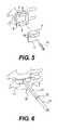
- FIG. 5the view according to FIG. 1 , without the adjustment instrument, with the guide device attached, and with milling gauge,
- FIGS. 6-14show a second embodiment, namely:
- FIG. 6a view of the inserted adjustment instrument corresponding to FIG. 1 .
- FIG. 7with a guide device pushed onto the adjustment rod
- FIG. 8a cross-sectional view of the guide device embodiment
- FIG. 9 aan end view of the guide device embodiment
- FIG. 9 ban end view of an alternate guide device embodiment
- FIG. 10a partial side view of the adjustment instrument
- FIG. 11a drill to be used with the guide device
- FIG. 12a screwdriver and screw pin to be used with the guide device
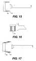
- FIG. 13a view, corresponding to FIG. 6 , with screw pins inserted into the vertebrae
- FIG. 14a view, corresponding to FIG. 13 , with a spreader instrument applied
- FIGS. 15-23show rasp tools for a specific prosthesis, namely:
- FIGS. 15-20a set of three different rasps
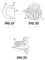
- FIG. 21the contour of the rasps for comparison
- FIGS. 22-23the prosthesis for which the rasps are intended.
- an intervertebral joint prosthesisis to be inserted into the intervertebral space 1 of the vertebral bodies 2 .
- those faces of the vertebral bodies 2 facing one anotherhave to be worked. Sensitive areas lie close by.
- a machining gauge 3is to be used which can be secured on the vertebral bodies 2 at a predetermined position. This is done using the guide device 4 .
- the latteris frame-shaped with an opening 6 which is designed to match a projection 7 on the gauge 3 .
- the adjustment instrument 10For positioning it, the adjustment instrument 10 is provided. It comprises an intervertebral plate 11 and an adjustment rod 12 connected rigidly to the latter.
- the intervertebral plate 11has a surface area which is slightly smaller than the surface area of the intervertebral space 1 . Its thickness is generally not greater than that of an intervertebral joint prosthesis. It is at any rate of such a size that, after removal of the intervertebral disk, it can be fitted into the intervertebral space 1 and there is held securely in its assigned position by means of the natural tension prevailing between the vertebral bodies 2 . It has a transverse bore 13 , and an AP bore 14 which the guide rod 12 also passes through.
- the adjustment rod 12then has an exactly defined position in relation to the vertebral surfaces enclosing the intervertebral plate 11 .
- the intermediate adjustment piece 18is provided that, just like the milling gauge 3 , has a projection 7 fitting into the opening 6 . It has a bore 19 matching the external diameter of the adjustment rod 12 .
- the partsare first joined together so that, by virtue of their friction or other suitable means of adhesion, they are connected sufficiently firmly to one another for manipulation. They are then placed with the bore 19 onto the rod 14 and can slide along the latter until the guide device 4 bears on the ventral faces of the vertebral bodies 2 .
- the guide device 4sits on the adjustment rod 12 via the intermediate adjustment piece 18 guarantees that it has exactly the right height with respect to the vertebral end faces which delimit the intervertebral space 1 . It is true that it can turn about the rod 12 , but no real incorrect setting is possible in this respect. If one wishes also to reliably avoid this, the adjustment rod 12 and the associated opening 19 are not cylindrical in shape but instead prismatic, for example having a rectangular cross section.
- the guide device 4As soon as the guide device 4 has reached the intended position on the vertebrae 2 , as is shown in FIG. 4 , it is secured to the vertebral bodies 2 by means of fine bone screws through its bores 8 . The intermediate adjustment piece 18 and the intervertebral plate 11 can now be removed through the opening 6 . This gives the situation shown in FIG. 5 .
- any desired machining gauges 3can now be fitted into the opening 6 of the guide device 4 , these machining gauges 3 having cutouts 20 adapted to and guiding the machining tools respectively used.
- the slit 20 shown in FIG. 5can serve to guide a cylindrical milling cutter 21 which is used to work the prosthesis contact surface of the upper vertebral body 2 .
- the machining gaugeis turned through 180°.
- the intervertebral space thus formedhas the predetermined dimensions for receiving the prosthesis.
- the lattercan now be fitted.
- the guide devicecan be removed beforehand (but does not need to be).
- the second illustrative embodiment shown in FIGS. 6-14uses an adjustment instrument 30 whose intervertebral plate 11 can be the same as the one described in the first example. It can be wedge-shaped in side view, as is shown in FIG. 10 .
- the main difference from the first illustrative embodimentis that the adjustment rod 32 has a square cross section, at least in its area 31 near the intervertebral plate 11 , while the portion 33 farther away from this is shown with a round cross section.
- the adjustment rod 32is also designed in this case as a tube so as to be able to serve as an X-ray marker for an X-ray beam path extending in the AP direction.
- the tube shapeis not necessary, because the outer contour of the adjustment rod can also serve as an X-ray marker.
- An X-ray apparatus having at least an AP beam pathis thus used to check the central position of the intervertebral plate and its orientation with respect to the median plane, the position and direction of the outer surfaces of the adjustment rod 32 being critical here. They form the X-ray marker of the instrument for this check.
- the adjustment rodis made radiopaque, for example of metal.
- a lateral beam pathcan also be used to check whether the intervertebral plate has the correct depth setting in the AP direction.
- the X-ray markeris formed by those edges of the intervertebral plate which extend in the LM direction, or by a special marker such as the bore 13 in FIG. 1 .
- the depth setting of the intervertebral plateis less important for the positioning of the prosthesis.
- the intervertebral plateis secured in the intervertebral space by the tensioning of the natural ligaments. Its height corresponds to that of the prosthesis to be implanted. If prostheses of different sizes are available, corresponding intervertebral plates are also included in the instrument set.
- the adjustment rod 32is used for adjusting (positioning) the guide device 34 .
- the latterhas a bore 35 with a square cross section which matches the portion 31 of the adjustment rod 32 .
- This part of the guide deviceforms a hub by which it is held on the adjustment rod. It also comprises a bore 36 of round cross section parallel to the bore 35 .
- This bore 36serves as a drill gauge or more generally for guiding work tools.
- the guide device 34is thus used first for working one vertebra, and it is then turned through 180° in order to work the other vertebra.
- This workinvolves first making a hole in a vertebra by means of a drill 39 whose shaft is designed to match the bore 36 , into which hole a screw pin 41 is then introduced by means of the screwdriver 40 whose shaft likewise matches the bore 36 .
- the pin 41fits exactly into a bore provided in the screwdriver 40 , and this ensures that it is screwed into the respective vertebra flush with the screwdriver 40 and thus also flush with the axes 37 , 38 .
- the picture shown in FIG. 13is reached.
- the screw pins 41protrude ventrally from both vertebrae 2 exactly in the median plane and parallel to one another.
- a distraction instrumentcan now be applied to the pins 41 , said instrument having two arms 42 , each of them with a receiving part 43 for the pins 41 , and the arms 42 can be positioned on an instrument body 44 and distracted parallel to one another in arrow direction 45 .
- the vertebrae 2can, if necessary, be distracted slightly further so that the intervertebral plate 11 can be removed. If so desired, the intervertebral space can be worked in the state in which the vertebrae are held by the instrument 42 to 44 and the pins 41 , in order to prepare to receive the intervertebral prosthesis. Finally, the latter is itself fitted into the intervertebral space and obtains its final position when the distraction of the vertebrae 2 with the instrument 42 to 44 is reversed.
- the instrument setalso comprises a collection of rasps which are used to prepare the surface shape of the vertebrae for receiving the prosthesis. These are shown in FIGS. 15 through 21 . The examples shown are indicated for the illustrative embodiment of the prosthesis shown in FIGS. 22 and 23 . It has an oval to rectangular contour designed to extensively utilize the area of the intervertebral space. It is so flat that it can be fitted without deep milling of the cover plates of the vertebral bodies. It has outer surfaces facing the cover plates of the vertebral bodies, these outer surfaces being approximately level and serrated in their largest part 50 . Their dorsolateral corners 51 are beveled so that the surface in these areas is set back from the plane of the surface part 50 .
- FIG. 21shows the graded sizes of the rasps.
- the smallest rasp 52is first pushed into the intervertebral space, using a handpiece (not shown), in order to open up the access.
- rasp 53which has a trapezoid shape, roughly corresponding to the trapezoid shape of the level surface portion of the prosthesis surface.
- rasp 54shapes the intervertebral space substantially to the shape of the prosthesis to be fitted. The height of the rasps is the same as that of the prosthesis.
- All the raspsare designed without teeth in those surfaces corresponding to the level part of the prosthesis 50 . This means that they effect only a slight abrasion with their front edge 55 .
Landscapes
- Health & Medical Sciences (AREA)
- Engineering & Computer Science (AREA)
- Orthopedic Medicine & Surgery (AREA)
- Life Sciences & Earth Sciences (AREA)
- Microelectronics & Electronic Packaging (AREA)
- Biomedical Technology (AREA)
- Manufacturing & Machinery (AREA)
- Transplantation (AREA)
- Oral & Maxillofacial Surgery (AREA)
- Veterinary Medicine (AREA)
- Surgery (AREA)
- General Health & Medical Sciences (AREA)
- Heart & Thoracic Surgery (AREA)
- Public Health (AREA)
- Animal Behavior & Ethology (AREA)
- Medical Informatics (AREA)
- Molecular Biology (AREA)
- Nuclear Medicine, Radiotherapy & Molecular Imaging (AREA)
- Operations Research (AREA)
- Neurology (AREA)
- Physical Education & Sports Medicine (AREA)
- Dentistry (AREA)
- Cardiology (AREA)
- Vascular Medicine (AREA)
- Supply And Installment Of Electrical Components (AREA)
- Prostheses (AREA)
Abstract
Description
- a) an adjustment device consisting of an intervertebral plate and of an adjustment rod projecting from the latter,
- b) a guide device which is supported loosely by the adjustment rod and which forms two guide axes lying in the median plane below and above the adjustment rod and parallel to the latter, these axes being intended for a cylindrical turning instrument,
- c) two pins which can be introduced into the vertebral bodies parallel to one another by means of the turning instrument, and
- d) a spreader instrument holding the pins parallel.
Claims (1)
Priority Applications (23)
| Application Number | Priority Date | Filing Date | Title |
|---|---|---|---|
| US10/731,432US7527629B2 (en) | 2002-03-12 | 2003-12-10 | Instrument set for fitting an intervertebral joint prosthesis |
| JP2006543416AJP4728964B2 (en) | 2003-12-10 | 2004-11-24 | Tool set for inserting intervertebral joint prostheses |
| ES07006418TES2320705T3 (en) | 2003-12-10 | 2004-11-24 | INSTRUMENTAL TO CONFORM AN INTERVERTEBRAL SPACE. |
| EP04798069AEP1694215B1 (en) | 2003-12-10 | 2004-11-24 | Instrument for the insertion of an intervertebral articular prosthesis |
| RU2006125404/14ARU2322212C1 (en) | 2003-12-10 | 2004-11-24 | Instrument set for implantation of implant of intervertebral joint |
| EP07006418AEP1808132B1 (en) | 2003-12-10 | 2004-11-24 | Instrument for shaping an intervertebral space |
| DE502004008844TDE502004008844D1 (en) | 2003-12-10 | 2004-11-24 | Instrument for shaping an intervertebral space |
| CNB200480036660XACN100405982C (en) | 2003-12-10 | 2004-11-24 | Device for inserting an intervertebral prosthesis into an intervertebral space between two vertebral bodies |
| AT04798069TATE454853T1 (en) | 2003-12-10 | 2004-11-24 | INSTRUMENTS FOR INSERTING AN INTERVERTEBRAL JOINT PROSTHESIS |
| DE502004010650TDE502004010650D1 (en) | 2003-12-10 | 2004-11-24 | INSTRUMENTARIUM FOR USING AN INTERMEDIATE JOINT PROSTHESIS |
| AT07006418TATE419793T1 (en) | 2003-12-10 | 2004-11-24 | INSTRUMENTS FOR SHAPING AN INTERVERBEL SPACE |
| PL07006418TPL1808132T3 (en) | 2003-12-10 | 2004-11-24 | Instrument for shaping an intervertebral space |
| AU2004296536AAU2004296536B2 (en) | 2003-12-10 | 2004-11-24 | Instrument Set for Inserting an Intervertebral Joint Prosthesis |
| CNA2008100879511ACN101288609A (en) | 2003-12-10 | 2004-11-24 | Instrument for the insertion of an intervertebral articular prosthesis |
| CA002547986ACA2547986A1 (en) | 2003-12-10 | 2004-11-24 | Instrument set for inserting an intervertebral joint prosthesis |
| ES04798069TES2339666T3 (en) | 2003-12-10 | 2004-11-24 | INSTRUMENTAL TO INSERT AN INTERVERTEBRAL ARTICULATION PROTESIS. |
| BRPI0417445-3ABRPI0417445A (en) | 2003-12-10 | 2004-11-24 | instrument group to insert an intervertebral union prosthesis |
| PCT/EP2004/013346WO2005055835A2 (en) | 2003-12-10 | 2004-11-24 | Instrument for the insertion of an intervertebral articular prosthesis |
| KR1020067011371AKR101096381B1 (en) | 2003-12-10 | 2004-11-24 | Mechanisms for insertion of intervertebral prostheses |
| ARP040104436AAR052514A1 (en) | 2003-12-10 | 2004-11-29 | INSTRUMENTAL TO INSERT AN INTERVERTEBRAL PROTESIS IN AN INTERVERTEBRAL INTERSTICE BETWEEN TWO VERTEBRAL BODIES |
| IL175854AIL175854A (en) | 2003-12-10 | 2006-05-23 | Instrument for the insertion of an intervertebral articular prosthesis |
| ZA200605651AZA200605651B (en) | 2003-12-10 | 2006-07-10 | Instrument for the insertion of an intervertebral articular prosthesis |
| US12/408,358US20090182341A1 (en) | 2002-03-12 | 2009-03-20 | Instrument set for fitting an intervertebral jont prosthesis |
Applications Claiming Priority (6)
| Application Number | Priority Date | Filing Date | Title |
|---|---|---|---|
| EP02005629AEP1344493B1 (en) | 2002-03-12 | 2002-03-12 | Instument set for insertion of intervertebral prostheses |
| EP02005629.7 | 2002-03-12 | ||
| JP2002358150AJP2004193261A (en) | 2002-12-10 | 2002-12-10 | Electronic component mounting device |
| JP2002-358150 | 2002-12-10 | ||
| US10/357,516US20040010259A1 (en) | 2002-03-12 | 2003-02-04 | Cervical prosthesis and instrumentation therefor |
| US10/731,432US7527629B2 (en) | 2002-03-12 | 2003-12-10 | Instrument set for fitting an intervertebral joint prosthesis |
Related Parent Applications (1)
| Application Number | Title | Priority Date | Filing Date |
|---|---|---|---|
| US10/357,516Continuation-In-PartUS20040010259A1 (en) | 2002-03-12 | 2003-02-04 | Cervical prosthesis and instrumentation therefor |
Related Child Applications (1)
| Application Number | Title | Priority Date | Filing Date |
|---|---|---|---|
| US12/408,358ContinuationUS20090182341A1 (en) | 2002-03-12 | 2009-03-20 | Instrument set for fitting an intervertebral jont prosthesis |
Publications (2)
| Publication Number | Publication Date |
|---|---|
| US20040177494A1 US20040177494A1 (en) | 2004-09-16 |
| US7527629B2true US7527629B2 (en) | 2009-05-05 |
Family
ID=41050978
Family Applications (1)
| Application Number | Title | Priority Date | Filing Date |
|---|---|---|---|
| US10/731,432Expired - LifetimeUS7527629B2 (en) | 2002-03-12 | 2003-12-10 | Instrument set for fitting an intervertebral joint prosthesis |
Country Status (1)
| Country | Link |
|---|---|
| US (1) | US7527629B2 (en) |
Cited By (21)
| Publication number | Priority date | Publication date | Assignee | Title |
|---|---|---|---|---|
| US20060084986A1 (en)* | 2004-09-30 | 2006-04-20 | Depuy Spine, Inc. | Instrument and method for the insertion and alignment of an intervertebral implant |
| US20080009881A1 (en)* | 2004-05-11 | 2008-01-10 | Geoffrey Blatt | Artificial spinal disc, insertion tool, and method of insertion |
| US20080045966A1 (en)* | 2002-01-14 | 2008-02-21 | Dynamic Spine, Inc. | Apparatus and method for performing spinal surgery |
| US20100106190A1 (en)* | 2008-10-23 | 2010-04-29 | Linares Medical Devices, Llc | Support insert associated with spinal vertebrae |
| US20120215259A1 (en)* | 2009-10-22 | 2012-08-23 | Blue Fury Consulting, Llc | Posterior cervical fusion system and techniques |
| US20140058400A1 (en)* | 2005-05-27 | 2014-02-27 | Spinecore, Inc. | Instruments and methods for inserting artificial intervertebral implants |
| US20160113773A1 (en)* | 2013-05-31 | 2016-04-28 | Orthopaedic & Spine Development (Osd) | Intervertebral prosthesis for introduction via posterior approach |
| US20160213494A1 (en)* | 2005-05-27 | 2016-07-28 | Spinecore, Inc. | Intervertebral disc and insertion methods therefor |
| US10098674B2 (en) | 2009-10-22 | 2018-10-16 | Nuvasive, Inc. | System and method for posterior cervical fusion |
| US10321833B2 (en) | 2016-10-05 | 2019-06-18 | Innovative Surgical Solutions. | Neural locating method |
| US10376209B2 (en) | 2013-09-20 | 2019-08-13 | Innovative Surgical Solutions, Llc | Neural locating method |
| US10376208B2 (en) | 2013-09-20 | 2019-08-13 | Innovative Surgical Solutions, Llc | Nerve mapping system |
| US10449002B2 (en) | 2013-09-20 | 2019-10-22 | Innovative Surgical Solutions, Llc | Method of mapping a nerve |
| US10478096B2 (en) | 2013-08-13 | 2019-11-19 | Innovative Surgical Solutions. | Neural event detection |
| US10478097B2 (en) | 2013-08-13 | 2019-11-19 | Innovative Surgical Solutions | Neural event detection |
| US10869616B2 (en) | 2018-06-01 | 2020-12-22 | DePuy Synthes Products, Inc. | Neural event detection |
| US10870002B2 (en) | 2018-10-12 | 2020-12-22 | DePuy Synthes Products, Inc. | Neuromuscular sensing device with multi-sensor array |
| US11298244B2 (en)* | 2019-01-31 | 2022-04-12 | K2M, Inc. | Interbody implants and instrumentation |
| US11399777B2 (en) | 2019-09-27 | 2022-08-02 | DePuy Synthes Products, Inc. | Intraoperative neural monitoring system and method |
| US11534307B2 (en) | 2019-09-16 | 2022-12-27 | K2M, Inc. | 3D printed cervical standalone implant |
| US11793558B2 (en) | 2019-08-30 | 2023-10-24 | K2M, Inc. | All in one plate holder and spring loaded awl |
Families Citing this family (4)
| Publication number | Priority date | Publication date | Assignee | Title |
|---|---|---|---|---|
| RU2400186C2 (en)* | 2005-04-11 | 2010-09-27 | Имплиант Лтд. | Introduction of anterior and posterior spinal prostheses |
| CN101883604A (en)* | 2006-11-28 | 2010-11-10 | 康隆有限公司 | Tissue prosthesis insertion system and method |
| CN105706543B (en)* | 2013-10-31 | 2018-09-28 | 富士机械制造株式会社 | Component Mounting Machine |
| CN108029233B (en)* | 2015-07-28 | 2020-02-28 | 株式会社富士 | Component Mounter |
Citations (56)
| Publication number | Priority date | Publication date | Assignee | Title |
|---|---|---|---|---|
| US4289123A (en) | 1980-03-31 | 1981-09-15 | Dunn Harold K | Orthopedic appliance |
| US4672957A (en) | 1983-10-04 | 1987-06-16 | South African Inventions Development Corporation | Surgical device |
| US4820305A (en) | 1986-11-03 | 1989-04-11 | Harms Juergen | Place holder, in particular for a vertebra body |
| EP0333990A2 (en) | 1988-03-23 | 1989-09-27 | Waldemar Link (GmbH & Co.) | Surgical instrument set |
| US4892545A (en) | 1988-07-14 | 1990-01-09 | Ohio Medical Instrument Company, Inc. | Vertebral lock |
| US4936848A (en) | 1989-09-22 | 1990-06-26 | Bagby George W | Implant for vertebrae |
| US5059194A (en) | 1990-02-12 | 1991-10-22 | Michelson Gary K | Cervical distractor |
| DE9217816U1 (en) | 1992-12-30 | 1994-05-05 | Synthes AG, Chur, Graubünden | Aiming device for placing pedicle screws in a vertebral body |
| US5397364A (en) | 1993-10-12 | 1995-03-14 | Danek Medical, Inc. | Anterior interbody fusion device |
| US5484437A (en) | 1988-06-13 | 1996-01-16 | Michelson; Gary K. | Apparatus and method of inserting spinal implants |
| US5534005A (en) | 1994-10-05 | 1996-07-09 | Smith & Nephew Richards, Inc. | Surgical milling system |
| US5591235A (en) | 1995-03-15 | 1997-01-07 | Kuslich; Stephen D. | Spinal fixation device |
| FR2737656A1 (en) | 1995-08-09 | 1997-02-14 | Jbs Sa | IMPACTOR DEVICE FOR PLACING A PROSTHESIS FOR INTERVERTEBRAL DISCS |
| WO1997038635A1 (en) | 1996-04-12 | 1997-10-23 | Surgical Dynamics, Inc. | Surgical cutting device removably connected to a rotary drive element |
| US5735856A (en) | 1997-01-31 | 1998-04-07 | Johnson & Johnson Professional, Inc. | Orthopedic cutting guide and bushing |
| US5772661A (en) | 1988-06-13 | 1998-06-30 | Michelson; Gary Karlin | Methods and instrumentation for the surgical correction of human thoracic and lumbar spinal disease from the antero-lateral aspect of the spine |
| US5797909A (en) | 1988-06-13 | 1998-08-25 | Michelson; Gary Karlin | Apparatus for inserting spinal implants |
| DE29916078U1 (en) | 1999-09-14 | 1999-11-25 | Aesculap Ag & Co Kg | Insertion tool for an intervertebral implant |
| DE19836498A1 (en) | 1998-08-12 | 2000-02-17 | Medinorm Ag | Device for expanding the space between vertebrae when fitting a bone tissue implant using spigots |
| US6063088A (en)* | 1997-03-24 | 2000-05-16 | United States Surgical Corporation | Method and instrumentation for implant insertion |
| US6083228A (en) | 1998-06-09 | 2000-07-04 | Michelson; Gary K. | Device and method for preparing a space between adjacent vertebrae to receive an insert |
| US6086595A (en) | 1997-08-29 | 2000-07-11 | Sulzer Spine-Tech Inc. | Apparatus and method for spinal stabilization |
| WO2000053127A1 (en) | 1999-03-11 | 2000-09-14 | Sulzer Spine-Tech Inc. | Intervertebral disc prosthesis and method |
| US6159214A (en) | 1996-07-31 | 2000-12-12 | Michelson; Gary K. | Milling instrumentation and method for preparing a space between adjacent vertebral bodies |
| WO2001013807A2 (en) | 1999-08-26 | 2001-03-01 | Sdgi Holdings, Inc. | Devices and methods for implanting fusion cages |
| US6224599B1 (en) | 1999-05-19 | 2001-05-01 | Matthew G. Baynham | Viewable wedge distractor device |
| US6224607B1 (en) | 1999-01-25 | 2001-05-01 | Gary K. Michelson | Instrumentation and method for creating an intervertebral space for receiving an implant |
| WO2001049188A1 (en) | 2000-01-06 | 2001-07-12 | Spinal Concepts, Inc. | Instrument and method for implanting an interbody fusion device |
| US6277122B1 (en) | 1999-10-15 | 2001-08-21 | Sdgi Holdings, Inc. | Distraction instrument with fins for maintaining insertion location |
| DE20110402U1 (en) | 2001-06-23 | 2001-08-23 | AlloCon GmbH, 42929 Wermelskirchen | Peg plate |
| DE20110393U1 (en) | 2001-06-23 | 2001-08-23 | AlloCon GmbH, 42929 Wermelskirchen | Peg plate |
| WO2001062166A2 (en) | 2000-02-22 | 2001-08-30 | Sdgi Holdings, Inc. | Instruments and techniques for disc space preparation |
| US6296647B1 (en) | 1998-08-07 | 2001-10-02 | Stryker Trauma Gmbh | Instrument for the positioning of an implant in the human spine |
| DE20111479U1 (en) | 2001-07-04 | 2001-10-04 | Aesculap AG & Co. KG, 78532 Tuttlingen | Vertebral distractor |
| US6332887B1 (en) | 1999-04-06 | 2001-12-25 | Benjamin D. Knox | Spinal fusion instrumentation system |
| US20020026191A1 (en) | 2000-08-10 | 2002-02-28 | Dixon Robert A. | Cam action vertebral spreader |
| US20020058944A1 (en) | 2000-12-14 | 2002-05-16 | Michelson Gary K. | Spinal interspace shaper |
| US20020068941A1 (en) | 2000-07-06 | 2002-06-06 | Hanson David A. | Bone preparation instruments and methods |
| US6447545B1 (en) | 2000-07-01 | 2002-09-10 | George W. Bagby | Self-aligning bone implant |
| US20020138079A1 (en) | 2001-03-23 | 2002-09-26 | Surgical Dynamics, Inc | Instrumentation for implant insertion |
| US20030028197A1 (en) | 2000-07-06 | 2003-02-06 | Hanson David A. | Bone implants and methods |
| US6517544B1 (en) | 1998-06-09 | 2003-02-11 | Gary K. Michelson | Device and method for preparing a space between adjacent vertebrae to receive an insert |
| US20030045938A1 (en) | 1997-03-06 | 2003-03-06 | Sulzer Spine-Tech Inc. | Lordotic spinal implant |
| US6540735B1 (en) | 2000-05-12 | 2003-04-01 | Sub-Q, Inc. | System and method for facilitating hemostasis of blood vessel punctures with absorbable sponge |
| US20030135217A1 (en)* | 2002-01-14 | 2003-07-17 | Buttermann Glenn Robin | Apparatus and method for performing spinal surgery |
| US20030135277A1 (en) | 2001-11-26 | 2003-07-17 | Sdgi Holdings, Inc. | Implantable joint prosthesis and associated instrumentation |
| WO2003075774A1 (en) | 2002-03-12 | 2003-09-18 | Cervitech Inc. | Apparatus for preparing an intervertbral space in order to receive an intervertebral-joint prosthesis |
| US20030220689A1 (en) | 2002-03-21 | 2003-11-27 | Stephen Ritland | Device and method for assisting in positioning implants |
| US20040156168A1 (en) | 2003-02-12 | 2004-08-12 | Levasseur Lewis H. | Sealed force-based touch sensor |
| US20040176843A1 (en) | 2003-03-06 | 2004-09-09 | Rafail Zubok | Instrumentation and methods for use in implanting a cervical disc replacement device |
| US20040186482A1 (en) | 2003-03-21 | 2004-09-23 | Kolb Eric D. | Modular drill guide |
| US20040193272A1 (en) | 2003-03-06 | 2004-09-30 | Rafail Zubok | Instrumentation and methods for use in implanting a cervical disc replacement device |
| WO2004089258A1 (en) | 2003-04-07 | 2004-10-21 | Cervitech, Inc. | Prosthetic joint of cervical intervertebral for a cervical spine |
| DE202004014768U1 (en) | 2004-09-21 | 2004-11-18 | Arnold Medizintechnik Gmbh | Device for distraction of vertebral bodies during operation, comprising one holding arm attached to movable sleeve |
| US20040236342A1 (en) | 2002-04-23 | 2004-11-25 | Ferree Bret A. | Device to assess ADR motion |
| US20050015092A1 (en) | 2003-07-16 | 2005-01-20 | Rathbun David S. | Plating system with multiple function drill guide |
Family Cites Families (1)
| Publication number | Priority date | Publication date | Assignee | Title |
|---|---|---|---|---|
| JP3554615B2 (en)* | 1995-07-19 | 2004-08-18 | 株式会社日立ハイテクインスツルメンツ | Electronic component mounting device |
- 2003
- 2003-12-10USUS10/731,432patent/US7527629B2/ennot_activeExpired - Lifetime
Patent Citations (77)
| Publication number | Priority date | Publication date | Assignee | Title |
|---|---|---|---|---|
| US4289123A (en) | 1980-03-31 | 1981-09-15 | Dunn Harold K | Orthopedic appliance |
| US4672957A (en) | 1983-10-04 | 1987-06-16 | South African Inventions Development Corporation | Surgical device |
| US4820305A (en) | 1986-11-03 | 1989-04-11 | Harms Juergen | Place holder, in particular for a vertebra body |
| EP0333990A2 (en) | 1988-03-23 | 1989-09-27 | Waldemar Link (GmbH & Co.) | Surgical instrument set |
| US6270498B1 (en) | 1988-06-13 | 2001-08-07 | Gary Karlin Michelson | Apparatus for inserting spinal implants |
| US6080155A (en) | 1988-06-13 | 2000-06-27 | Michelson; Gary Karlin | Method of inserting and preloading spinal implants |
| US5797909A (en) | 1988-06-13 | 1998-08-25 | Michelson; Gary Karlin | Apparatus for inserting spinal implants |
| US5772661A (en) | 1988-06-13 | 1998-06-30 | Michelson; Gary Karlin | Methods and instrumentation for the surgical correction of human thoracic and lumbar spinal disease from the antero-lateral aspect of the spine |
| US6096038A (en) | 1988-06-13 | 2000-08-01 | Michelson; Gary Karlin | Apparatus for inserting spinal implants |
| US5484437A (en) | 1988-06-13 | 1996-01-16 | Michelson; Gary K. | Apparatus and method of inserting spinal implants |
| US4892545A (en) | 1988-07-14 | 1990-01-09 | Ohio Medical Instrument Company, Inc. | Vertebral lock |
| US4936848A (en) | 1989-09-22 | 1990-06-26 | Bagby George W | Implant for vertebrae |
| US5059194A (en) | 1990-02-12 | 1991-10-22 | Michelson Gary K | Cervical distractor |
| DE9217816U1 (en) | 1992-12-30 | 1994-05-05 | Synthes AG, Chur, Graubünden | Aiming device for placing pedicle screws in a vertebral body |
| US5397364A (en) | 1993-10-12 | 1995-03-14 | Danek Medical, Inc. | Anterior interbody fusion device |
| US5534005A (en) | 1994-10-05 | 1996-07-09 | Smith & Nephew Richards, Inc. | Surgical milling system |
| US20020091390A1 (en) | 1995-02-27 | 2002-07-11 | Michelson Gary Karlin | Methods and instrumentation for the surgical correction of human thoracic and lumbar spinal disease from the lateral aspect of the spine |
| US5591235A (en) | 1995-03-15 | 1997-01-07 | Kuslich; Stephen D. | Spinal fixation device |
| FR2737656A1 (en) | 1995-08-09 | 1997-02-14 | Jbs Sa | IMPACTOR DEVICE FOR PLACING A PROSTHESIS FOR INTERVERTEBRAL DISCS |
| WO1997038635A1 (en) | 1996-04-12 | 1997-10-23 | Surgical Dynamics, Inc. | Surgical cutting device removably connected to a rotary drive element |
| US6440139B2 (en) | 1996-07-31 | 2002-08-27 | Gary K. Michelson | Milling instrumentation and method for preparing a space between adjacent vertebral bodies |
| US20020091392A1 (en) | 1996-07-31 | 2002-07-11 | Michelson Gary K. | Milling instrumentation and method for preparing a space between adjacent vertebral bodies |
| US20010000532A1 (en) | 1996-07-31 | 2001-04-26 | Michelson Gary K. | Milling instrumentation and method for preparing a space between adjacent vertebral bodies |
| US6159214A (en) | 1996-07-31 | 2000-12-12 | Michelson; Gary K. | Milling instrumentation and method for preparing a space between adjacent vertebral bodies |
| US5735856A (en) | 1997-01-31 | 1998-04-07 | Johnson & Johnson Professional, Inc. | Orthopedic cutting guide and bushing |
| US20030045938A1 (en) | 1997-03-06 | 2003-03-06 | Sulzer Spine-Tech Inc. | Lordotic spinal implant |
| US6063088A (en)* | 1997-03-24 | 2000-05-16 | United States Surgical Corporation | Method and instrumentation for implant insertion |
| US6562041B1 (en) | 1997-08-29 | 2003-05-13 | Sulzer Spine-Tech Inc. | Apparatus and method for spinal stabilization |
| US6156040A (en) | 1997-08-29 | 2000-12-05 | Sulzer Spine-Tech Inc. | Apparatus and method for spinal stablization |
| US6086595A (en) | 1997-08-29 | 2000-07-11 | Sulzer Spine-Tech Inc. | Apparatus and method for spinal stabilization |
| US6083228A (en) | 1998-06-09 | 2000-07-04 | Michelson; Gary K. | Device and method for preparing a space between adjacent vertebrae to receive an insert |
| US6517544B1 (en) | 1998-06-09 | 2003-02-11 | Gary K. Michelson | Device and method for preparing a space between adjacent vertebrae to receive an insert |
| US6296647B1 (en) | 1998-08-07 | 2001-10-02 | Stryker Trauma Gmbh | Instrument for the positioning of an implant in the human spine |
| DE19836498A1 (en) | 1998-08-12 | 2000-02-17 | Medinorm Ag | Device for expanding the space between vertebrae when fitting a bone tissue implant using spigots |
| US20010010001A1 (en) | 1999-01-25 | 2001-07-26 | Michelson Gary K. | Instrumentation and method for creating an intervertebral space for receiving an implant |
| US20010010002A1 (en) | 1999-01-25 | 2001-07-26 | Michelson Gary K. | Instrumentation and method for creating an intervertebral space for receiving an implant |
| US6224607B1 (en) | 1999-01-25 | 2001-05-01 | Gary K. Michelson | Instrumentation and method for creating an intervertebral space for receiving an implant |
| WO2000053127A1 (en) | 1999-03-11 | 2000-09-14 | Sulzer Spine-Tech Inc. | Intervertebral disc prosthesis and method |
| US6740087B2 (en) | 1999-04-06 | 2004-05-25 | Benjamin D. Knox | Spinal fusion instrumentation system |
| US6332887B1 (en) | 1999-04-06 | 2001-12-25 | Benjamin D. Knox | Spinal fusion instrumentation system |
| US6224599B1 (en) | 1999-05-19 | 2001-05-01 | Matthew G. Baynham | Viewable wedge distractor device |
| WO2001013807A2 (en) | 1999-08-26 | 2001-03-01 | Sdgi Holdings, Inc. | Devices and methods for implanting fusion cages |
| DE29916078U1 (en) | 1999-09-14 | 1999-11-25 | Aesculap Ag & Co Kg | Insertion tool for an intervertebral implant |
| US6277122B1 (en) | 1999-10-15 | 2001-08-21 | Sdgi Holdings, Inc. | Distraction instrument with fins for maintaining insertion location |
| WO2001049188A1 (en) | 2000-01-06 | 2001-07-12 | Spinal Concepts, Inc. | Instrument and method for implanting an interbody fusion device |
| US6447512B1 (en) | 2000-01-06 | 2002-09-10 | Spinal Concepts, Inc. | Instrument and method for implanting an interbody fusion device |
| WO2001062166A2 (en) | 2000-02-22 | 2001-08-30 | Sdgi Holdings, Inc. | Instruments and techniques for disc space preparation |
| US20030032962A1 (en)* | 2000-02-22 | 2003-02-13 | Mcgahan Thomas V. | Instruments and techniques for disc space preparation |
| US6540735B1 (en) | 2000-05-12 | 2003-04-01 | Sub-Q, Inc. | System and method for facilitating hemostasis of blood vessel punctures with absorbable sponge |
| US6447545B1 (en) | 2000-07-01 | 2002-09-10 | George W. Bagby | Self-aligning bone implant |
| US20020068941A1 (en) | 2000-07-06 | 2002-06-06 | Hanson David A. | Bone preparation instruments and methods |
| US20030028197A1 (en) | 2000-07-06 | 2003-02-06 | Hanson David A. | Bone implants and methods |
| US20020026191A1 (en) | 2000-08-10 | 2002-02-28 | Dixon Robert A. | Cam action vertebral spreader |
| US20020058944A1 (en) | 2000-12-14 | 2002-05-16 | Michelson Gary K. | Spinal interspace shaper |
| US20020138079A1 (en) | 2001-03-23 | 2002-09-26 | Surgical Dynamics, Inc | Instrumentation for implant insertion |
| DE10226496A1 (en) | 2001-06-23 | 2003-01-16 | Allocon Gmbh | Vertebra plate for fixing vertebrae together comprises a fixing element arranged in a recess with its longitudinal axis at various angles to the longitudinal axis of the recess |
| DE20110393U1 (en) | 2001-06-23 | 2001-08-23 | AlloCon GmbH, 42929 Wermelskirchen | Peg plate |
| DE20110402U1 (en) | 2001-06-23 | 2001-08-23 | AlloCon GmbH, 42929 Wermelskirchen | Peg plate |
| DE20111479U1 (en) | 2001-07-04 | 2001-10-04 | Aesculap AG & Co. KG, 78532 Tuttlingen | Vertebral distractor |
| DE10134505A1 (en) | 2001-07-04 | 2003-01-23 | Aesculap Ag & Co Kg | Spine traction appliance has holder with fixtures, guide for tool, guide surface, elongated opening and adjustment and tool |
| US20030135277A1 (en) | 2001-11-26 | 2003-07-17 | Sdgi Holdings, Inc. | Implantable joint prosthesis and associated instrumentation |
| US7025787B2 (en)* | 2001-11-26 | 2006-04-11 | Sdgi Holdings, Inc. | Implantable joint prosthesis and associated instrumentation |
| US20040092943A1 (en)* | 2002-01-14 | 2004-05-13 | Buttermann Glenn Robin | Apparatus and method for performing spinal surgery |
| US6761723B2 (en)* | 2002-01-14 | 2004-07-13 | Dynamic Spine, Inc. | Apparatus and method for performing spinal surgery |
| US20030135217A1 (en)* | 2002-01-14 | 2003-07-17 | Buttermann Glenn Robin | Apparatus and method for performing spinal surgery |
| WO2003075774A1 (en) | 2002-03-12 | 2003-09-18 | Cervitech Inc. | Apparatus for preparing an intervertbral space in order to receive an intervertebral-joint prosthesis |
| US20030220689A1 (en) | 2002-03-21 | 2003-11-27 | Stephen Ritland | Device and method for assisting in positioning implants |
| US20040236342A1 (en) | 2002-04-23 | 2004-11-25 | Ferree Bret A. | Device to assess ADR motion |
| US20040156168A1 (en) | 2003-02-12 | 2004-08-12 | Levasseur Lewis H. | Sealed force-based touch sensor |
| US20040176843A1 (en) | 2003-03-06 | 2004-09-09 | Rafail Zubok | Instrumentation and methods for use in implanting a cervical disc replacement device |
| US20040193272A1 (en) | 2003-03-06 | 2004-09-30 | Rafail Zubok | Instrumentation and methods for use in implanting a cervical disc replacement device |
| US20040220590A1 (en) | 2003-03-06 | 2004-11-04 | Rafail Zubok | Instrumentation and methods for use in implanting a cervical disc replacement device |
| US20040176772A1 (en) | 2003-03-06 | 2004-09-09 | Rafail Zubok | Instrumentation and methods for use in implanting a cervical disc replacement device |
| US20040186482A1 (en) | 2003-03-21 | 2004-09-23 | Kolb Eric D. | Modular drill guide |
| WO2004089258A1 (en) | 2003-04-07 | 2004-10-21 | Cervitech, Inc. | Prosthetic joint of cervical intervertebral for a cervical spine |
| US20050015092A1 (en) | 2003-07-16 | 2005-01-20 | Rathbun David S. | Plating system with multiple function drill guide |
| DE202004014768U1 (en) | 2004-09-21 | 2004-11-18 | Arnold Medizintechnik Gmbh | Device for distraction of vertebral bodies during operation, comprising one holding arm attached to movable sleeve |
Non-Patent Citations (5)
| Title |
|---|
| International Search Report dated Jun. 23, 2005 directed to counterpart PCT/EP2004/013346 (8 pages). |
| International Search Report dated Mar. 22, 2005. |
| International Search Report mailed Jul. 17, 2003, directed to related foreign application. |
| Search protocol dated Mar. 30, 2005 showing the family information of WO 2004080333. |
| Search Report dated Mar. 18, 2005. |
Cited By (55)
| Publication number | Priority date | Publication date | Assignee | Title |
|---|---|---|---|---|
| US20080045966A1 (en)* | 2002-01-14 | 2008-02-21 | Dynamic Spine, Inc. | Apparatus and method for performing spinal surgery |
| US20080009881A1 (en)* | 2004-05-11 | 2008-01-10 | Geoffrey Blatt | Artificial spinal disc, insertion tool, and method of insertion |
| US7909878B2 (en)* | 2004-05-11 | 2011-03-22 | Geoffrey Blatt | Artificial spinal disc, insertion tool, and method of insertion |
| US20060084986A1 (en)* | 2004-09-30 | 2006-04-20 | Depuy Spine, Inc. | Instrument and method for the insertion and alignment of an intervertebral implant |
| US8298235B2 (en)* | 2004-09-30 | 2012-10-30 | Depuy Spine, Inc. | Instrument and method for the insertion and alignment of an intervertebral implant |
| US20160213494A1 (en)* | 2005-05-27 | 2016-07-28 | Spinecore, Inc. | Intervertebral disc and insertion methods therefor |
| US10213322B2 (en) | 2005-05-27 | 2019-02-26 | Spinecore, Inc. | Intervertebral disc and insertion methods therefor |
| US9782272B2 (en) | 2005-05-27 | 2017-10-10 | Spinecore, Inc. | Intervertebral disc and insertion methods therefor |
| US10245154B2 (en) | 2005-05-27 | 2019-04-02 | Spinecore, Inc. | Instruments and methods for inserting artificial intervertebral implants |
| US9622882B2 (en) | 2005-05-27 | 2017-04-18 | Spinecore, Inc. | Intervertebral disc and insertion methods therefor |
| US9539114B2 (en)* | 2005-05-27 | 2017-01-10 | Spinecore, Inc. | Instruments and methods for inserting artificial intervertebral implants |
| US9526634B2 (en)* | 2005-05-27 | 2016-12-27 | Spinecore, Inc. | Intervertebral disc and insertion methods therefor |
| US20140058400A1 (en)* | 2005-05-27 | 2014-02-27 | Spinecore, Inc. | Instruments and methods for inserting artificial intervertebral implants |
| US10835389B2 (en) | 2005-05-27 | 2020-11-17 | Howmedica Osteonics Corp. | Intervertebral disc and insertion methods therefor |
| US11642231B2 (en) | 2005-05-27 | 2023-05-09 | Howmedica Osteonics Corp. | Intervertebral disc and insertion methods therefor |
| US20100106190A1 (en)* | 2008-10-23 | 2010-04-29 | Linares Medical Devices, Llc | Support insert associated with spinal vertebrae |
| US8623056B2 (en) | 2008-10-23 | 2014-01-07 | Linares Medical Devices, Llc | Support insert associated with spinal vertebrae |
| US8617212B2 (en) | 2008-10-23 | 2013-12-31 | Linares Medical Devices, Llc | Inter-vertebral support kit including main insert jack and dual secondary auxiliary support jacks located between succeeding transverse processes |
| US8613758B2 (en) | 2008-10-23 | 2013-12-24 | Linares Medical Devices, Llc | Two piece spinal jack incorporating varying mechanical and fluidic lift mechanisms for establishing a desired spacing between succeeding vertebrae |
| US8585738B2 (en) | 2008-10-23 | 2013-11-19 | Miguel A. Linares | One and two piece spinal jack incorporating varying mechanical pivot, hinge and cam lift constructions for establishing a desired spacing between succeeding vertebrae |
| US8574267B2 (en) | 2008-10-23 | 2013-11-05 | Linares Medical Devices, Llc | Assembleable jack braces for seating and supporting angular processes |
| US10098674B2 (en) | 2009-10-22 | 2018-10-16 | Nuvasive, Inc. | System and method for posterior cervical fusion |
| US9204906B2 (en)* | 2009-10-22 | 2015-12-08 | Nuvasive, Inc. | Posterior cervical fusion system and techniques |
| US20120215259A1 (en)* | 2009-10-22 | 2012-08-23 | Blue Fury Consulting, Llc | Posterior cervical fusion system and techniques |
| US9737410B2 (en)* | 2013-05-31 | 2017-08-22 | Orthopaedic & Spine Development (Osd) | Intervertebral prosthesis for introduction via posterior approach |
| US20160113773A1 (en)* | 2013-05-31 | 2016-04-28 | Orthopaedic & Spine Development (Osd) | Intervertebral prosthesis for introduction via posterior approach |
| US10478096B2 (en) | 2013-08-13 | 2019-11-19 | Innovative Surgical Solutions. | Neural event detection |
| US10478097B2 (en) | 2013-08-13 | 2019-11-19 | Innovative Surgical Solutions | Neural event detection |
| US10376208B2 (en) | 2013-09-20 | 2019-08-13 | Innovative Surgical Solutions, Llc | Nerve mapping system |
| US10376209B2 (en) | 2013-09-20 | 2019-08-13 | Innovative Surgical Solutions, Llc | Neural locating method |
| US10449002B2 (en) | 2013-09-20 | 2019-10-22 | Innovative Surgical Solutions, Llc | Method of mapping a nerve |
| US10321833B2 (en) | 2016-10-05 | 2019-06-18 | Innovative Surgical Solutions. | Neural locating method |
| US12109042B2 (en) | 2016-10-05 | 2024-10-08 | Innovative Surgical Solutions, Llc | Neural locating system and method |
| US11311222B2 (en) | 2016-10-05 | 2022-04-26 | Innovative Surgical Solutions | Neural locating system |
| US10869616B2 (en) | 2018-06-01 | 2020-12-22 | DePuy Synthes Products, Inc. | Neural event detection |
| US10870002B2 (en) | 2018-10-12 | 2020-12-22 | DePuy Synthes Products, Inc. | Neuromuscular sensing device with multi-sensor array |
| US12090320B2 (en) | 2018-10-12 | 2024-09-17 | DePuy Synthes Products, Inc. | Neuromuscular sensing device with multi-sensor array |
| US20220183858A1 (en)* | 2019-01-31 | 2022-06-16 | K2M, Inc. | Interbody Implants And Instrumentation |
| US20240197495A1 (en)* | 2019-01-31 | 2024-06-20 | K2M, Inc. | Interbody Implants And Instrumentation |
| US20220409399A1 (en)* | 2019-01-31 | 2022-12-29 | K2M, Inc. | Tritanium Al Implants And Instrumentation |
| US11617659B2 (en)* | 2019-01-31 | 2023-04-04 | K2M, Inc. | Tritanium Al implants and instrumentation |
| US20220387192A1 (en)* | 2019-01-31 | 2022-12-08 | K2M, Inc. | Tritanium AL Implants And Instrumentation |
| US20230190491A1 (en)* | 2019-01-31 | 2023-06-22 | K2M, Inc. | Tritanium al implants and instrumentation |
| US12303401B2 (en)* | 2019-01-31 | 2025-05-20 | K2M, Inc. | Tritanium AL implants and instrumentation |
| US11918487B2 (en)* | 2019-01-31 | 2024-03-05 | K2M, Inc. | Interbody implants and instrumentation |
| US11969357B2 (en)* | 2019-01-31 | 2024-04-30 | K2M, Inc. | Tritanium AL implants and instrumentation |
| US12226320B2 (en)* | 2019-01-31 | 2025-02-18 | K2M, Inc. | Tritanium AL implants and instrumentation |
| US20240216148A1 (en)* | 2019-01-31 | 2024-07-04 | K2M, Inc. | Tritanium AL Implants And Instrumentation |
| US11298244B2 (en)* | 2019-01-31 | 2022-04-12 | K2M, Inc. | Interbody implants and instrumentation |
| US12201335B2 (en) | 2019-08-30 | 2025-01-21 | K2M, Inc. | All in one plate holder and spring loaded awl |
| US11793558B2 (en) | 2019-08-30 | 2023-10-24 | K2M, Inc. | All in one plate holder and spring loaded awl |
| US11534307B2 (en) | 2019-09-16 | 2022-12-27 | K2M, Inc. | 3D printed cervical standalone implant |
| US12409045B2 (en) | 2019-09-16 | 2025-09-09 | Vb Spine Us Opco Llc | 3D printed cervical standalone implant |
| US11399777B2 (en) | 2019-09-27 | 2022-08-02 | DePuy Synthes Products, Inc. | Intraoperative neural monitoring system and method |
| US12303301B2 (en) | 2019-09-27 | 2025-05-20 | DePuy Synthes Products, Inc. | Intraoperative neural monitoring system and method |
Also Published As
| Publication number | Publication date |
|---|---|
| US20040177494A1 (en) | 2004-09-16 |
Similar Documents
| Publication | Publication Date | Title |
|---|---|---|
| US7527629B2 (en) | Instrument set for fitting an intervertebral joint prosthesis | |
| US20090182341A1 (en) | Instrument set for fitting an intervertebral jont prosthesis | |
| AU2003223960B2 (en) | Instrument set for fitting an intervertebral joint prosthesis for the cervical spine | |
| US8206397B2 (en) | Instruments and techniques for disc space preparation | |
| KR101263782B1 (en) | Instrumentation and Methods for Inserting an Intervertebral Disc Prosthesis | |
| US7300441B2 (en) | Technique and instrumentation for preparation of vertebral members | |
| US7635370B2 (en) | Bone removal device | |
| US6635060B2 (en) | Bone preparation instruments and methods | |
| US20040059337A1 (en) | Bone preparation instruments and methods | |
| AU2001241612A1 (en) | Instruments and techniques for disc space preparation | |
| US20060276800A1 (en) | Intervertebral disc replacement and surgical instruments therefor | |
| ZA200605651B (en) | Instrument for the insertion of an intervertebral articular prosthesis | |
| AU2004296536B2 (en) | Instrument Set for Inserting an Intervertebral Joint Prosthesis | |
| JP2007513657A5 (en) | ||
| MXPA06006559A (en) | Instrument for the insertion of an intervertebral articular prosthesis |
Legal Events
| Date | Code | Title | Description |
|---|---|---|---|
| AS | Assignment | Owner name:CERVITECH, INC., NEW JERSEY Free format text:ASSIGNMENT OF ASSIGNORS INTEREST;ASSIGNORS:LINK, HELMUT D.;KELLER, ARNOLD;MCAFFE, PAUL C.;REEL/FRAME:015332/0673 Effective date:20040116 | |
| STCF | Information on status: patent grant | Free format text:PATENTED CASE | |
| AS | Assignment | Owner name:CERVITECH, INC., CALIFORNIA Free format text:CHANGE OF ADDRESS;ASSIGNOR:CERVITECH, INC.;REEL/FRAME:023035/0968 Effective date:20090508 Owner name:CERVITECH, INC.,CALIFORNIA Free format text:CHANGE OF ADDRESS;ASSIGNOR:CERVITECH, INC.;REEL/FRAME:023035/0968 Effective date:20090508 | |
| CC | Certificate of correction | ||
| FPAY | Fee payment | Year of fee payment:4 | |
| FPAY | Fee payment | Year of fee payment:8 | |
| AS | Assignment | Owner name:BANK OF AMERICA, N.A., AS ADMINISTRATIVE AGENT, CALIFORNIA Free format text:NOTICE OF GRANT OF SECURITY INTEREST IN PATENTS;ASSIGNORS:NUVASIVE, INC.;IMPULSE MONITORING, INC.;REEL/FRAME:040634/0404 Effective date:20160208 Owner name:BANK OF AMERICA, N.A., AS ADMINISTRATIVE AGENT, CA Free format text:NOTICE OF GRANT OF SECURITY INTEREST IN PATENTS;ASSIGNORS:NUVASIVE, INC.;IMPULSE MONITORING, INC.;REEL/FRAME:040634/0404 Effective date:20160208 | |
| AS | Assignment | Owner name:BANK OF AMERICA, N.A., AS ADMINISTRATIVE AGENT, TE Free format text:NOTICE OF GRANT OF SECURITY INTEREST IN PATENTS;ASSIGNORS:NUVASIVE, INC.;BIOTRONIC NATIONAL, LLC;NUVASIVE CLINICAL SERVICES MONITORING, INC.;AND OTHERS;REEL/FRAME:042490/0236 Effective date:20170425 Owner name:BANK OF AMERICA, N.A., AS ADMINISTRATIVE AGENT, TEXAS Free format text:NOTICE OF GRANT OF SECURITY INTEREST IN PATENTS;ASSIGNORS:NUVASIVE, INC.;BIOTRONIC NATIONAL, LLC;NUVASIVE CLINICAL SERVICES MONITORING, INC.;AND OTHERS;REEL/FRAME:042490/0236 Effective date:20170425 | |
| AS | Assignment | Owner name:BANK OF AMERICA, N.A., AS ADMINISTRATIVE AGENT, NORTH CAROLINA Free format text:SECURITY INTEREST;ASSIGNORS:NUVASIVE, INC.;NUVASIVE CLINICAL SERVICES MONITORING, INC.;NUVASIVE CLINICAL SERVICES, INC.;AND OTHERS;REEL/FRAME:052918/0595 Effective date:20200224 | |
| MAFP | Maintenance fee payment | Free format text:PAYMENT OF MAINTENANCE FEE, 12TH YEAR, LARGE ENTITY (ORIGINAL EVENT CODE: M1553); ENTITY STATUS OF PATENT OWNER: LARGE ENTITY Year of fee payment:12 |