US7526966B2 - Apparatus and method for measuring a parameter of a multiphase flow - Google Patents
Apparatus and method for measuring a parameter of a multiphase flowDownload PDFInfo
- Publication number
- US7526966B2 US7526966B2US11/652,363US65236307AUS7526966B2US 7526966 B2US7526966 B2US 7526966B2US 65236307 AUS65236307 AUS 65236307AUS 7526966 B2US7526966 B2US 7526966B2
- Authority
- US
- United States
- Prior art keywords
- flow
- pipe
- sensing device
- fluid
- sound
- Prior art date
- Legal status (The legal status is an assumption and is not a legal conclusion. Google has not performed a legal analysis and makes no representation as to the accuracy of the status listed.)
- Active, expires
Links
- 238000000034methodMethods0.000titleclaimsdescription64
- 239000012530fluidSubstances0.000claimsabstractdescription100
- XLYOFNOQVPJJNP-UHFFFAOYSA-NwaterSubstancesOXLYOFNOQVPJJNP-UHFFFAOYSA-N0.000claimsabstractdescription17
- 238000005259measurementMethods0.000claimsdescription58
- 239000007788liquidSubstances0.000claimsdescription49
- 230000008569processEffects0.000claimsdescription42
- 238000012545processingMethods0.000claimsdescription35
- 238000009434installationMethods0.000claimsdescription2
- 239000000203mixtureSubstances0.000abstractdescription52
- 239000011800void materialSubstances0.000abstractdescription12
- 239000007789gasSubstances0.000description64
- 239000012071phaseSubstances0.000description39
- 230000001902propagating effectEffects0.000description31
- 230000006870functionEffects0.000description20
- 238000010586diagramMethods0.000description14
- 239000003921oilSubstances0.000description13
- 230000000694effectsEffects0.000description10
- 230000002123temporal effectEffects0.000description10
- 239000000463materialSubstances0.000description8
- 230000008901benefitEffects0.000description6
- 230000003595spectral effectEffects0.000description5
- 230000003044adaptive effectEffects0.000description4
- 239000007791liquid phaseSubstances0.000description4
- 238000004519manufacturing processMethods0.000description4
- 239000002033PVDF binderSubstances0.000description3
- 230000001427coherent effectEffects0.000description3
- 238000007906compressionMethods0.000description3
- 230000006835compressionEffects0.000description3
- 230000000875corresponding effectEffects0.000description3
- 239000010779crude oilSubstances0.000description3
- 239000000835fiberSubstances0.000description3
- 230000003287optical effectEffects0.000description3
- 239000002245particleSubstances0.000description3
- 229920002981polyvinylidene fluoridePolymers0.000description3
- 230000004044responseEffects0.000description3
- 238000005070samplingMethods0.000description3
- 230000035945sensitivityEffects0.000description3
- 238000000926separation methodMethods0.000description3
- 239000000126substanceSubstances0.000description3
- 238000005273aerationMethods0.000description2
- 230000005540biological transmissionEffects0.000description2
- 238000009530blood pressure measurementMethods0.000description2
- 238000012937correctionMethods0.000description2
- 238000000354decomposition reactionMethods0.000description2
- 230000001934delayEffects0.000description2
- 238000001739density measurementMethods0.000description2
- 230000001419dependent effectEffects0.000description2
- 239000006185dispersionSubstances0.000description2
- 238000000605extractionMethods0.000description2
- 238000011068loading methodMethods0.000description2
- 238000005457optimizationMethods0.000description2
- 239000000123paperSubstances0.000description2
- 239000003208petroleumSubstances0.000description2
- 239000002002slurrySubstances0.000description2
- 238000013517stratificationMethods0.000description2
- 238000012935AveragingMethods0.000description1
- 238000012369In process controlMethods0.000description1
- 230000001133accelerationEffects0.000description1
- 238000007792additionMethods0.000description1
- 238000013459approachMethods0.000description1
- 238000003491arrayMethods0.000description1
- 230000003190augmentative effectEffects0.000description1
- 230000009286beneficial effectEffects0.000description1
- 230000008859changeEffects0.000description1
- 230000001276controlling effectEffects0.000description1
- 229920001577copolymerPolymers0.000description1
- 230000002596correlated effectEffects0.000description1
- 238000005260corrosionMethods0.000description1
- 230000007797corrosionEffects0.000description1
- 238000006073displacement reactionMethods0.000description1
- 238000005516engineering processMethods0.000description1
- 230000005284excitationEffects0.000description1
- 238000001914filtrationMethods0.000description1
- 238000010304firingMethods0.000description1
- 229920002313fluoropolymerPolymers0.000description1
- 239000004811fluoropolymerSubstances0.000description1
- 239000011888foilSubstances0.000description1
- 238000009472formulationMethods0.000description1
- 229930195733hydrocarbonNatural products0.000description1
- 150000002430hydrocarbonsChemical class0.000description1
- 230000006872improvementEffects0.000description1
- 238000010965in-process controlMethods0.000description1
- 229910052500inorganic mineralInorganic materials0.000description1
- 238000012423maintenanceMethods0.000description1
- 238000000691measurement methodMethods0.000description1
- 238000004377microelectronicMethods0.000description1
- 239000011707mineralSubstances0.000description1
- 238000005065miningMethods0.000description1
- 238000002156mixingMethods0.000description1
- 238000012986modificationMethods0.000description1
- 230000004048modificationEffects0.000description1
- 238000012544monitoring processMethods0.000description1
- 239000013307optical fiberSubstances0.000description1
- 229920000642polymerPolymers0.000description1
- -1pulpSubstances0.000description1
- 239000010453quartzSubstances0.000description1
- VYPSYNLAJGMNEJ-UHFFFAOYSA-Nsilicon dioxideInorganic materialsO=[Si]=OVYPSYNLAJGMNEJ-UHFFFAOYSA-N0.000description1
- 239000008247solid mixtureSubstances0.000description1
- 239000007790solid phaseSubstances0.000description1
- 238000010183spectrum analysisMethods0.000description1
- 239000000758substrateSubstances0.000description1
- 238000012360testing methodMethods0.000description1
- 238000012546transferMethods0.000description1
- 230000007704transitionEffects0.000description1
- 239000002023woodSubstances0.000description1
Images


Classifications
- G—PHYSICS
- G01—MEASURING; TESTING
- G01F—MEASURING VOLUME, VOLUME FLOW, MASS FLOW OR LIQUID LEVEL; METERING BY VOLUME
- G01F1/00—Measuring the volume flow or mass flow of fluid or fluent solid material wherein the fluid passes through a meter in a continuous flow
- G01F1/66—Measuring the volume flow or mass flow of fluid or fluent solid material wherein the fluid passes through a meter in a continuous flow by measuring frequency, phase shift or propagation time of electromagnetic or other waves, e.g. using ultrasonic flowmeters
- G01F1/667—Arrangements of transducers for ultrasonic flowmeters; Circuits for operating ultrasonic flowmeters
- G01F1/668—Compensating or correcting for variations in velocity of sound
- G—PHYSICS
- G01—MEASURING; TESTING
- G01F—MEASURING VOLUME, VOLUME FLOW, MASS FLOW OR LIQUID LEVEL; METERING BY VOLUME
- G01F1/00—Measuring the volume flow or mass flow of fluid or fluent solid material wherein the fluid passes through a meter in a continuous flow
- G01F1/74—Devices for measuring flow of a fluid or flow of a fluent solid material in suspension in another fluid
- G—PHYSICS
- G01—MEASURING; TESTING
- G01F—MEASURING VOLUME, VOLUME FLOW, MASS FLOW OR LIQUID LEVEL; METERING BY VOLUME
- G01F15/00—Details of, or accessories for, apparatus of groups G01F1/00 - G01F13/00 insofar as such details or appliances are not adapted to particular types of such apparatus
- G01F15/005—Valves
Definitions
- This inventionrelates to an apparatus for measuring a parameter of a process flow passing within a pipe, and more particularly to a flow measurement apparatus having ultrasonic sensors and an array of strain-based sensors and for processing data signals therefrom to provide an output indicative of the speed of sound propagating through the process flow and/or a flow parameter of the process flow passing through a pipe.
- Accuracy of oil production measurementis limited to three constraints.
- One constraintinvolves the inability to ensure the complete separation of gas and liquid flow. This constraint results in an inaccurate liquid volume determination, inaccurate gas volume determination and an inaccurate watercut determination.
- the second constraintinvolves the relatively low number of flow measurements available due to maintenance requirements, installation requirements and pressure drop in the point with any increase in measurement points.
- the third constraintinvolves the very low number of watercut measurement points, which is due to the reliability of the watercut measurement devices and the calibration requirements of the meters.
- a reliable, non-intrusive, clamp-on apparatuscapable of measuring the parameters of an aerated multiphase fluid flow, such as the volumetric flow rate liquid of the process flow, the gas volume (or void) fraction of the flow, the watercut of the flow, and the volumetric flow rate of each of the phases of the flow.
- the present inventionprovides such an apparatus.
- An apparatus for determining a characteristic of an aerated fluid flowing within a pipewherein the apparatus includes at least one first sensing device associated with the pipe.
- the at least one first sensing deviceis configured to sense a low-frequency component and a high-frequency component of the aerated fluid flow, wherein the at least one first sensing device generates first sensor data responsive to the low-frequency component of the aerated fluid and second sensor data responsive to the high-frequency component of the aerated fluid flow.
- at least one second sensing deviceis included and is associated with the pipe to sense predetermined parameters of the aerated fluid flow and to generate third sensor data responsive to the predetermined parameters of the aerated fluid flow.
- a processing deviceis included, wherein the processing device is communicated with the at least one first sensing device and the at least one second sensing device to receive and process the first sensor data, the second sensor data and the third sensor data to generate fluid data responsive to a characteristic of the aerated fluid flow.
- FIG. 1is a block diagram of a flow measurement apparatus having an array of strain-based sensors and an array of ultrasonic sensors for measuring parameters of a multiphase flow in accordance with the present invention.
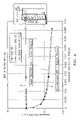
- FIG. 2is a plot of the measured speed of sound normalized to the speed of sound of the liquid over a frequency range in accordance with the present invention.
- FIG. 3is a plot of the measured speed of sound normalized to the speed of sound of the liquid as a function of gas volume fraction in accordance with the present invention.
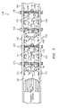
- FIG. 4is a schematic diagram of a flow measurement apparatus of FIG. 1 having an array of strain-based sensors and an array of ultrasonic sensors for measuring parameters of a multiphase flow.
- FIG. 5is a cross-sectional view of a pipe having a turbulent fluid flow or mixture flowing therein, the flow having coherent structures therein, namely acoustic waves and vortical disturbances, in accordance with the present invention.
- FIG. 6is a block diagram of the GVF Logic in accordance with the present invention.
- FIG. 7is a block diagram of the GVF Logic in accordance with the present invention.
- FIG. 8is a schematic diagram of a speed of sound (SOS) logic of an array processor of a flow measuring apparatus in accordance with the present invention.
- SOSspeed of sound
- FIG. 9is a k ⁇ plot of data processed from an apparatus embodying the present invention that illustrates the slopes of a pair of acoustic ridges, in accordance with the present invention.
- FIG. 10is a plot of mixture sound speed as a function of gas volume fraction over a range of process pressures, in accordance with the present invention.
- FIG. 11is a schematic diagram of a flow logic of an array processor of a flow measuring apparatus in accordance with the present invention.
- FIG. 12a k ⁇ plot of data processed from an apparatus embodying the present invention that illustrates the slope of a convective ridge, and a plot of the optimization function of the convective ridge, in accordance with the present invention.
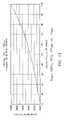
- FIG. 13is a plot of the speed of sound of the liquid as a function of the volume fraction of the water in the multiphase flow in accordance with the present invention.
- FIG. 14is a block diagram of another embodiment of a flow measurement apparatus having an array of strain-based sensors and ultrasonic sensors for measuring parameters of a multiphase flow in accordance with the present invention.
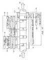
- FIG. 15is a schematic diagram of a flow measurement apparatus of FIG. 14 having an array of strain-based sensors and an array of ultrasonic sensors for measuring parameters of a multiphase flow.
- FIG. 16is a schematic diagram of a flow measurement apparatus similar to that shown in FIG. 1 which includes a density and/or mass flow meter such as a coriolis meter.
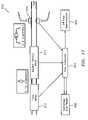
- FIG. 17is a clamp-on multi-phase (e.g. three phase) flow measurement apparatus comprising flow meter similar to that shown in FIG. 15 having an array of strain-based sensors, a clamp-on density meter such as a nuclear densitometer, and at least one ultrasonic sensor to provide a watercut measurement, in accordance with the present invention.
- a clamp-on multi-phase flow measurement apparatuscomprising flow meter similar to that shown in FIG. 15 having an array of strain-based sensors, a clamp-on density meter such as a nuclear densitometer, and at least one ultrasonic sensor to provide a watercut measurement, in accordance with the present invention.
- FIG. 18is schematic diagram of a system for monitoring and measuring flow parameters of a fluid separator, wherein the three phase measurement device of FIG. 17 is provided on the input pipe of the separator, the flow measurement device of FIG. 16 is provided on the liquid leg of the separator, and the wet gas flow measurement device is provided on the gas leg of the separator.
- FIG. 1illustrates a block diagram of a flow measurement device 100 for measuring a parameter of a multiphase flow 102 passing through a pipe 104 .
- the multiphase flow or mixture 102includes any mixture having any combination of a gas, liquid, or solid phase and while the present invention is particularly useful in measuring multiphase flows, it should be appreciated that the apparatus 100 can also measure a parameter of a single phase flow.
- the apparatus embodying the present inventionis useful in measuring a multiphase flow comprising oil, water and gas. The description of the present invention will therefore assume that the mixture is a combination of oil, water, and gas, however, the invention contemplates that any single or multiphase flow can be measured.
- the apparatus 100functions as a gas volume fraction (or void fraction) meter, an ultrasonic flow meter, and an ultrasonic watercut meter.
- the gas volume fraction (GVF) meterprovides an output indicative of the gas volume fraction or void fraction of the mixture 102 by measuring the speed of sound propagating at low frequencies axially through the flow 102 in the pipe 104 .
- the ultrasonic flow meterprovides a plurality of high frequency acoustic signals through the flow 102 to provide output signals indicative of pressure disturbances (e.g., vortical disturbances) propagating with the flow 102 past the ultrasonic sensors, which will be described in greater detail hereinafter.
- the ultrasonic watercut metermeasures the speed of sound of a high frequency signal propagating through the flow 102 to provide an output signal indicative of the speed of sound of the liquid, which is indicative of the watercut of the mixture 102 , wherein watercut is the phase fraction or percentage of the water in the flow 102 .
- the apparatus 100is capable of measuring at least the flow velocity, the volumetric flow rate, the flow composition (e.g., phase fraction), the watercut, the volumetric flow rate of a phase of the mixture, the gas volume (void) fraction of the flow, the speed of sound of the mixture, and the speed of sound of the liquid.
- FIG. 2illustrates the frequency dependence of the speed of sound in bubbly fluids.
- the speed of sound propagating through the fluid 102is dramatically influenced by entrained gases.
- entrained gas in the fluid flow 102has no significant impact on the speed of sound propagating through the liquid.
- the apparatus 100 embodying the present inventionprovides a meter, such as a GVF meter, to measure the speed of sound at low frequencies below the bubble resonant frequency, and another meter, such as an ultrasonic watercut meter, to measure the speed of sound at high frequencies above the bubble resonant frequency.
- a metersuch as a GVF meter
- another metersuch as an ultrasonic watercut meter
- the measured speed of sound at the lower frequencyis indicative of the speed of sound of the mixture 102
- the measured speed of sound at the higher frequenciesis indicative of the speed of sound of the liquid. Knowing the speed of sound of the mixture 102 enables the gas volume (and void) fraction of the flow 102 (or mixture) to be determined. Further, knowing the speed of sound of the liquid enables the watercut to be determined. This processing will be described in greater detail hereinafter.
- Testswere performed using a vertical pipe filled with a fluid, wherein bubbles were injected into the fluid at the bottom of the pipe.
- the speed of sound at super-resonant frequencies and sub-resonant frequencies, respectivelywere measured.
- the data obtainedillustrates the phenomenon described hereinbefore that the measured speed of sound of the liquid (e.g., super-resonant SOS) is not affected by the entrained gas, while the measured speed of sound of the mixture 102 (e.g., sub-resonant SOS) is affected by the entrained gas.
- the data in FIG. 3illustrates the effects of the speed of sound of bubble mixtures or flows 102 .
- the measured speed of sound normalized by the liquid speed of soundis plotted as a function of the reference gas volume fraction.
- the line A in FIG. 3shows the normalized measured super-resonant speed of sound as a function of the referenced GVF.
- the measured speed of sound at higher frequenciesis not affected by entrained gas and is indicative of the speed of sound of the liquid regardless of the amount of entrained gas.
- the line B in FIG. 3shows the normalized measured sub-resonant speed of sound as a function of the referenced GVF.
- the measured sound speed at lower frequencies (sub-resonant)is affected by entrained gas by a known or determinable relationship, thus enabling the determination of the gas volume (or void) fraction of the multiphase flow or mixture 102 .
- the line C in FIG. 3shows the theoretical normalized sub-resonant speed of sound of the mixture 102 as a function of the referenced GVF in accordance with the Woods equation. As can be seen, the measured sub-resonant speed of sound correlates with the theoretical determination of the sub-resonant speed of sound.
- the flow measurement apparatus 100includes a sensing device (sensor head) 106 mounted to a pipe 104 and a processing unit or array processor (transmitter) 108 .
- the apparatus 100can determine the speed at which sound (i.e., acoustic wave 110 in FIG. 5 ) propagates through the fluid flow 102 within the pipe 104 to measure particular characteristics of the single or multi-phase fluids.
- the flow 102 propagating through the pipe 104will be referred to as a process flow with the understanding that the fluid or process flow 102 may be a single phase or multi-phase flow, as described hereinbefore.
- the sensing device 106comprises an array of strain-based sensors or pressure sensors 112 - 118 for measuring the unsteady pressures produced by acoustic pressure disturbances (e.g., acoustic waves 110 ) within the pipe 104 to determine the speed of sound propagating through the flow 102 .
- the sensing device 106further includes an array of ultrasonic sensors 120 - 126 , each of which have a transmitter 160 and a receiver 162 to also measure a parameter of the flow 102 .
- the pressure sensors 112 - 118 and ultrasonic sensors 120 - 126are shown interlaced, it should be appreciated that each respective sensor array may be partially interlaced or not interlaced at all without departing from the present invention. It is also contemplated that the GVF meter and the ultrasonic flow meter may be two distinct units disposed adjacent to each other on the pipe 104 .
- the pressure signals P 1 (t)-P N (t) generated by the pressure sensors 112 - 118 and the ultrasonic signals S 1 (t)-S N (t) generated by the ultrasonic sensors 120 - 126are provided to the processing unit 108 , which digitizes the signals and computes the appropriate flow parameter(s).
- a cableelectronically connects the sensing device 106 to the processing unit 108 .
- the analog pressure sensor signals P 1 (t)-P N (t)are typically 4-20 mA current loop signals.
- the array of pressure sensors 112 - 118comprises an array of at least two pressure sensors 118 , 120 spaced axially along the outer surface 132 of the pipe 104 , having a process flow 102 propagating therein.
- the pressure sensors 112 - 118may be clamped onto or generally removably mounted to the pipe 104 by any releasable fastener, such as bolts, screws and clamps.
- the sensors 112 - 118may be permanently attached to or integral (e.g., embedded) with the pipe 104 .
- the array of sensors 112 - 118 of the sensing device 106may include any number of pressure sensors 18 - 21 greater than two sensors, such as three, four, eight, sixteen or N number of sensors between two and twenty-four sensors.
- the accuracy of the measurementimproves as the number of sensors in the array increases, wherein the degree of accuracy provided by the greater number of sensors is typically offset by the increase in complexity and time for computing the desired output parameter of the flow 102 . Therefore, the number of sensors used is dependent at least in part on the degree of accuracy desired and the desire update rate of the output parameter provided by the apparatus 100 .
- the pressure sensors 112 - 118measure the unsteady pressures produced by acoustic waves propagating through the flow 102 within the pipe 104 , which are indicative of the SOS propagating through the fluid flow 102 in the pipe 104 .
- the output signals (P 1 (t)-P N (t)) of the pressure sensors 112 - 118are provided to a signal amplifier 134 that amplifies the signals generated by the pressure sensors 112 - 118 .
- the processing unit 108processes the pressure measurement data P 1 (t)-P N (t) and determines the desired parameters and characteristics of the flow 102 , as described hereinbefore.
- the apparatus 100also contemplates providing one or more acoustic sources 136 to enable the measurement of the speed of sound propagating through the flow 102 for instances of acoustically quiet flow.
- the acoustic source 136may be a device that taps or vibrates on the wall of the pipe 104 , for example.
- the acoustic sources 136may be disposed at the input end or the output end of the array of sensors 112 - 118 , or at both ends as shown.
- the passive noiseincludes noise generated by pumps, valves, motors, and the turbulent mixture itself.
- the processing unit 108measures unsteady pressures created by acoustical disturbances propagating through the flow 102 to determine the speed of sound (SOS) propagating through the flow 102 . Knowing the pressure and/or temperature of the flow 102 and the speed of sound of the acoustic disturbances or waves, as shown in FIG. 6 and FIG. 7 , the processing unit 108 can determine the volumetric flow of the fluid, the consistency or composition of the fluid, the Mach number of the fluid, the average size of particles flowing through the fluid, the air/mass ratio of the fluid, and/or the percentage of entrained air within the mixture 102 , such as that described in U.S. patent application Ser. No. 10/349,716, filed Jan. 23, 2003, U.S. patent application Ser. No. 10/376,427, filed Feb. 26, 2003, U.S. patent application Ser. No. 10/762,410, filed Jan. 21, 2004, which are all incorporated by reference.
- an apparatus 100 embodying the present inventionhas an array of at least two strain-based or pressure sensors 112 - 114 , located at two locations x 1 , x 2 axially along the pipe 104 for sensing respective stochastic signals propagating between the sensors 112 - 114 within the pipe 104 at their respective locations.
- Each sensor 112 - 114provides a signal indicating an unsteady pressure at the location of each sensor, at each instant in a series of sampling instants.
- the sensor arraymay include more than two pressure sensors as depicted by pressure sensors 116 , 118 at location x 3 , x N .
- the pressure generated by the acoustic waves 110see FIG.
- the pressure sensors 112 - 118provide analog pressure time-varying signals P 1 (t),P 2 (t),P 3 (t),P N (t) to the signal processing unit 108 .
- the SOS Mixture Logic 138includes a data acquisition unit 140 that digitizes the pressure signals P 1 (t)-P N (t) associated with the acoustic waves 110 propagating through the pipe 104 .
- An FFT logic 142calculates the Fourier transform of the digitized time-based input signals P 1 (t)-P N (t) and provide complex frequency domain (or frequency based) signals P 1 ( ⁇ ),P 2 ( ⁇ ),P 3 ( ⁇ ),P N ( ⁇ ) indicative of the frequency content of the input signals.
- a data accumulator 144accumulates the signals P 1 (t)-P N (t) from the sensors, and provides the data accumulated over a sampling interval to an array processor 146 , which performs a spatial-temporal (two-dimensional) transform of the sensor data, from the xt domain to the k- ⁇ domain, and then calculates the power in the k- ⁇ plane, as represented by a k- ⁇ plot, similar to that provided by the convective array processor 178 discussed further hereinafter.
- the array processor 146determines the wavelength and so the (spatial) wavenumber k, and also the (temporal) frequency and so the angular frequency ⁇ , of various of the spectral components of the stochastic parameter.
- the array processor 146determines the wavelength and so the (spatial) wavenumber k, and also the (temporal) frequency and so the angular frequency ⁇ , of various of the spectral components of the stochastic parameter.
- the array processor 146uses standard so-called beam forming, array processing, or adaptive array-processing algorithms, i.e. algorithms for processing the sensor signals using various delays and weighting to create suitable phase relationships between the signals provided by the different sensors, thereby creating phased antenna array functionality.
- One such technique of determining the speed of sound propagating through the flow 102involves using array processing techniques to define an acoustic ridge in the k- ⁇ plane as shown in FIG. 9 .
- the slope of the acoustic ridgeis indicative of the speed of sound propagating through the flow 102 .
- the speed of sound (SOS)is determined by applying sonar arraying processing techniques to determine the speed at which the one dimensional acoustic waves 110 propagate past the axial array of unsteady pressure measurements distributed along the pipe 104 .
- the apparatus 100 of the present inventionmeasures the speed of sound (SOS) of one-dimensional sound waves 110 (see FIG. 5 ) propagating through the mixture 102 to determine the gas volume fraction of the mixture 102 .
- SOSspeed of sound
- the speed of sound propagating through the pipe 104 and flow 102may be determined using a number of known techniques, such as those set forth in U.S. patent application Ser. No. 09/344,094, filed Jun. 25, 1999, now U.S. Pat. No. 6,354,147; U.S. patent application Ser. No. 10/795,111, filed Mar. 4, 2004; U.S. patent application Ser. No. 09/997,221, filed Nov.
- the power in the k- ⁇ plane shown in a k- ⁇ plot of FIG. 9 so determinedwill exhibit a structure that is called an acoustic ridge 150 , 152 in both the left and right planes of the plot, wherein one of the acoustic ridges 150 is indicative of the speed of sound traveling in one axial direction and the other acoustic ridge 152 being indicative of the speed of sound traveling in the other axial direction.
- the acoustic ridges 150 , 152represent the concentration of a stochastic parameter that propagates through the flow 102 and is a mathematical manifestation of the relationship between the spatial variations and temporal variations described above. Such a plot will indicate a tendency for k- ⁇ pairs to appear more or less along a line 150 , 152 with some slope, the slope indicating the speed of sound.
- the power in the k- ⁇ plane so determinedis then provided to an acoustic ridge identifier 154 , which uses one or another feature extraction method to determine the location and orientation (slope) of any acoustic ridge 150 , 152 present in the left and right k- ⁇ plane.
- An analyzer 156determines the speed of sound of the mixture 102 by using the slope of one of the two acoustic ridges 150 , 152 or averaging the slopes of the acoustic ridges 150 , 152 .
- the GVF logic 158provides output signals indicative of gas volume or void fraction of the mixture 102 in response to the measured speed of sound of the mixture 102 .
- the GVF logic 158assumes a nearly isothermal condition for the flow 102 .
- xis the speed of sound
- A1+rg/rl*(K eff /P ⁇ 1) ⁇ K eff /P
- BK eff /P ⁇ 2+rg/rl
- C1 ⁇ K eff /rl*a meas ⁇ 2)
- Rggas density
- rlliquid density
- K effeffective K (modulus of the liquid and pipewall)
- Ppressure
- a measmeasured speed of sound.
- the sound speed of a mixturecan be related to volumetric phase fraction ( ⁇ i ) of the components and the sound speed (a) and densities ( ⁇ ) of the component through the Wood equation.
- One dimensional compression waves propagating within a mixture 102 contained within a pipe 104exerts an unsteady internal pressure loading on the pipe 104 .
- the degree to which the pipe 104 displaces as a result of the unsteady pressure loadinginfluences the speed of propagation of the compression wave.
- the relationship among the infinite domain speed of sound and density of a mixture, the elastic modulus (E), thickness (t), and radius (R) of a vacuum-backed cylindrical conduit, and the effective propagation velocity (a eff ) for one dimensional compressionis given by the following expression:
- the mixing ruleessentially states that the compressibility of a mixture (1/( ⁇ a 2 )) is the volumetrically-weighted average of the compressibilities of the components.
- the compressibility of gas phaseis orders of magnitudes greater than that of the liquid.
- the compressibility of the gas phase and the density of the liquid phaseprimarily determine mixture sound speed, and as such, it is necessary to have a good estimate of process pressure to interpret mixture sound speed in terms of volumetric fraction of entrained gas.
- the effect of process pressure on the relationship between sound speed and entrained air volume fractionis shown in FIG. 10 .
- processing unit 108may be implemented in software (using a microprocessor or computer) and/or firmware, or may be implemented using analog and/or digital hardware, having sufficient memory, interfaces, and capacity to perform the functions described herein.
- the measurement apparatus 100includes a sensing device 106 comprising an array of ultrasonic sensor units 120 - 126 .
- Each sensor unit 120 - 126comprises a pair of ultrasonic sensors 160 , 162 , one of which functions as a transmitter (Tx) 160 and the other as a receiver (Rx) 162 .
- the sensor units 120 - 126are spaced axially along the outer surface 132 of the pipe 104 having a process flow 102 propagating therein.
- the pair of sensors 160 , 162is diametrically disposed on the pipe 104 at predetermined locations along the pipe 104 to provide a through transmission configuration, such that the sensors transmit and receive an ultrasonic signal that propagates through the fluid substantially orthogonal to the direction of the flow of the fluid within the pipe 104 .
- the ultrasonic measurement portion of the present inventionis similar to that shown in U.S. patent application No. 10/756,977 filed on Jan. 13, 2004, which is incorporated herein by reference.
- each pair of ultrasonic sensors 160 , 162measures a transit time (i.e., time of flight (TOF), or phase modulation) of an ultrasonic signal propagating through the fluid 102 from the transmitting sensor 160 to the receiving sensor 162 .
- the transit time measurement or variationis indicative of coherent properties that convect with the flow within the pipe 104 (e.g., vortical disturbances, inhomogenieties within the flow, temperature variations, bubbles, particles, pressure disturbances), which are indicative of the velocity of the process flow 102 .
- the ultrasonic sensors 160 , 162may operate at any frequency, however, it has been found that the higher frequency sensors are more suitable for single phase fluids while lower frequency sensors are more suitable for multiphase fluids.
- the optimum frequency of the ultrasonic sensors 160 , 162is dependent on the size or type of particle or substance propagating with the flow 102 . For instance, the larger the air bubbles in an aerated fluid the lower the desirable frequency of the ultrasonic signal. Examples of frequency used for a flow meter embodying the present invention are 1 MHz and 5 MHz.
- the ultrasonic sensors 160 , 162may also provide a pulsed, chirped or continuous signal through the fluid flow 102 .
- An example of the sensors 160 , 162 that may be usedare Model no. 113-241-591, manufactured by Krautkramer.
- An ultrasonic signal processor 164fires the sensors 160 , 162 in response to a firing signal from the transmitter 108 and receives the ultrasonic output signals S 1 (t)-S N (t) from the sensors 160 , 162 .
- the signal processor 164processes the data from each of the sensor units 120 - 126 to provide an analog or digital output signal T 1 (t)-T N (t) indicative of the time of flight or transit time of the ultrasonic signal through the fluid.
- the signal processor 164may also provide an output signal indicative of the amplitude (or attenuation) of the ultrasonic signals.
- One such signal processoris model no. USPC 2100 manufactured by Krautkramer Ultrasonic Systems. Measuring the amplitude of ultrasonic signals is particularly useful and works best for measuring the velocity of a fluid that includes a substance in the flow (e.g., multiphase fluid or slurry).
- the output signals (T 1 (t)-T N (t)) of the ultrasonic signal processor 164are provided to the processor 108 , which processes the transit time or modulation measurement data to determine the volumetric flow rate.
- the transit time or time of flight measurementis defined by the time it takes for an ultrasonic signal to propagate from the transmitting sensor 160 to the respective receiving sensor 162 through the pipe wall and the fluid 102 .
- the effect of the vortical disturbances (and/or other inhomogenities within the fluid) on the transit time of the ultrasonic signalis to delay or speed up the transit time.
- each sensing unit 120 - 126provides a respective output signal T 1 (t)-T N (t) indicative of the variations in the transit time of the ultrasonic signals propagating orthogonal to the direction of the fluid 102 .
- the measurementis derived by interpreting the convecting coherent property and/or characteristic within the process piping using at least two sensor units 120 , 122 .
- the ultrasonic sensors 120 - 126may be “wetted” or clamped onto the outer surface 132 of the pipe 104 (e.g. contact or non-contact sensor).
- the flow meter 100measures the volumetric flow rate by determining the velocity of vortical disturbances or “eddies” 168 (see FIG. 5 ) propagating with the flow 102 using the array of ultrasonic sensors 120 - 126 .
- the flow meter 100measures the velocities associated with unsteady flow fields created by vortical disturbances or “eddies” 168 and other inhomogenities to determine the velocity of the flow 102 .
- the ultrasonic sensor units 120 - 126measure the transmit time T 1 (t)-T N (t) of the respective ultrasonic signals between each respective pair of sensors 160 , 162 , which vary due to the vortical disturbances as these disturbances convect within the flow 102 through the pipe 104 in a known manner. Therefore, the velocity of these vortical disturbances is related to the velocity of the flow 102 and hence the volumetric flow rate may be determined, as will be described in greater detail hereinafter.
- the volumetric flowis determined by multiplying the velocity of the fluid by the cross-sectional area of the pipe 104 .
- the Flow Logic 170 of the processing unit 108processes the ultrasonic signals as shown in FIG. 11 , wherein the Flow Logic 170 receives the ultrasonic signals from the array of sensors 120 - 126 .
- a data acquisition unit 172e.g., A/D converter
- the FFT logic 174calculates the Fourier transform of the digitized time-based input signals T 1 (t)-T N (t) and provides complex frequency domain (or frequency based) signals T 1 ( ⁇ ), T 2 ( ⁇ ), T 3 ( ⁇ ), T N ( ⁇ ) indicative of the frequency content of the input signals.
- any other technique for obtaining the frequency domain characteristics of the signals T 1 (t)-T N (t),may be used.
- the cross-spectral density and the power spectral densitymay be used to form one or more frequency domain transfer functions (or frequency responses or ratios) discussed hereinafter.
- One technique of determining the convection velocity of the turbulent eddies 168 within the process flow 102is by characterizing a convective ridge of the resulting unsteady pressures using an array of sensors or other beam forming techniques, similar to that described in U.S. Pat. No.6,889,562 and U.S. Pat. No. 6,609,069, which are incorporated herein by reference.
- a data accumulator 176accumulates the frequency signals T 1 ( ⁇ )-T N ( ⁇ ) over a sampling interval, and provides the data to an array processor 178 , which performs a spatial-temporal (two-dimensional) transform of the sensor data, from the xt domain to the k- ⁇ domain, and then calculates the power in the k- ⁇ plane, as represented by a k- ⁇ plot.
- the array processor 178uses standard so-called beam forming, array processing, or adaptive array-processing algorithms, i.e. algorithms for processing the sensor signals using various delays and weighting to create suitable phase relationships between the signals provided by the different sensors, thereby creating phased antenna array functionality.
- the prior artteaches many algorithms of use in spatially and temporally decomposing a signal from a phased array of sensors, and the present invention is not restricted to any particular algorithm.
- One particular adaptive array processing algorithmis the Capon method/algorithm. While the Capon method is described as one method, the present invention contemplates the use of other adaptive array processing algorithms, such as MUSIC algorithm.
- the present inventionrecognizes that such techniques can be used to determine flow rate, i.e. that the signals caused by a stochastic parameter convecting with a flow are time stationary and have a coherence length long enough that it is practical to locate sensor units apart from each other and yet still be within the coherence length.
- uis the convection velocity (flow velocity).
- a plot of k- ⁇ pairsis obtained from a spectral analysis of sensor samples associated with convective parameters. The pairings are portrayed so that the energy of the disturbance spectrally corresponding to the pairings that can be described as a substantially straight ridge, a ridge that in turbulent boundary layer theory is called a convective ridge. What is being sensed are not discrete events of turbulent eddies 168 , but rather a continuum of possibly overlapping events forming a temporally stationary, essentially white process over the frequency range of interest. In other words, the convective eddies 168 are distributed over a range of length scales and hence temporal frequencies.
- the array processor 178determines the wavelength and so the (spatial) wavenumber k, and also the (temporal) frequency and so the angular frequency ⁇ , of various of the spectral components of the stochastic parameter.
- the array processor 178determines the wavelength and so the (spatial) wavenumber k, and also the (temporal) frequency and so the angular frequency ⁇ , of various of the spectral components of the stochastic parameter.
- the present inventionmay use temporal and spatial filtering to precondition the signals to effectively filter out the common mode characteristics P common mode and other long wavelength (compared to the sensor spacing) characteristics in the pipe 104 by differencing adjacent sensors and retaining a substantial portion of the stochastic parameter associated with the flow field and any other short wavelength (compared to the sensor spacing) low frequency stochastic parameters.
- the power in the k- ⁇ plane shown in a k- ⁇ plot of FIG. 12shows a convective ridge 180 .
- the convective ridge 180represents the concentration of a stochastic parameter that convects with the flow 102 and is a mathematical manifestation of the relationship between the spatial variations and temporal variations described above. Such a plot will indicate a tendency for k- ⁇ pairs to appear more or less along a line 180 with some slope, the slope indicating the flow velocity.
- a convective ridge identifier 182uses one or another feature extraction method to determine the location and orientation (slope) of any convective ridge 180 present in the k- ⁇ plane.
- a so-called slant stacking methodis used, a method in which the accumulated frequency of k- ⁇ pairs in the k- ⁇ plot along different rays emanating from the origin are compared, each different ray being associated with a different trial convection velocity (in that the slope of a ray is assumed to be the flow velocity or correlated to the flow velocity in a known way).
- the convective ridge identifier 182provides information about the different trial convection velocities, information referred to generally as convective ridge information.
- the watercut of the process flow 102is determined using the output of at least one of the sensors 120 - 126 of the ultrasonic flow meter. While an ultrasonic sensor 120 of the ultrasonic meter is used to determine the watercut of the flow 102 , it is contemplated that a separate ultrasonic sensor may be used to determine watercut. A separate ultrasonic sensor for measuring watercut would allow the sensor to transmit an ultrasonic signal at different frequencies to ensure the ultrasonic sensor for watercut is operating at a frequency greater than the bubble resonant frequency.
- the SOS Liquid Logic 186converts the measured transit time of the ultrasonic signal to a signal indicative of the speed of sound of the liquid.
- the frequency of the ultrasonic signal propagating through the fluidis greater than the bubble resonant frequency such that the entrained gas does not affect the ultrasonic signal.
- the phase fraction of the watercan be determined.
- the phase fraction of the wateris a function of the SOS of the liquid, the SOS of the oil, SOS of the water, the density of the oil, and the density of the water. Knowing the SOS and density of the oil and water, the relationship between the phase fraction (e.g., watercut) of the flow 102 and the SOS of the liquid is known. As shown in FIG. 13 , this relationship is illustrated in the plot of SOS of the liquid v. watercut, and therefore, knowing the SOS of the liquid, the watercut may be determined.
- sonar-based flow meterusing an array of sensors to measure the speed of sound of an acoustic wave propagating through the mixture 102 is shown and described, one will appreciate that any means for measuring the speed of sound of the acoustic wave may used to determine the entrained gas volume fraction of the mixture/fluid or other characteristics of the flow 102 described hereinbefore.
- data acquisition units 140 , 172 , FFT logic 142 , 174 , data accumulators 144 , 176 , array processors 146 , 178 and ridge identifiers 154 , 182are shown as separate elements or separate software/processing routines, one will appreciate that each of these elements may be common and able to process the data associated with both the pressure signals associated with the speed of sound and the pressures that convect with the process flow.
- each of the ultrasonic sensor units 120 - 126 of FIG. 1comprises a pair of ultrasonic sensors (transmitter and receiver) 160 , 162 diametrically-opposed to provide through transmission
- the present inventioncontemplates that one of the ultrasonic sensors 160 , 162 of each sensor unit 120 - 126 may be offset axially such that the ultrasonic signal from the transmitter sensor 160 has an axial component in its propagation direction.
- each sensing unit 120 - 126 of the sensing device 106may be configured in a pulse/echo configuration.
- each sensing unit 120 - 126comprises one ultrasonic sensor that transmits an ultrasonic signal through the pipe wall and fluid substantially orthogonal to the direction of flow and receives a reflection of the ultrasonic signal reflected back from the wall of the pipe to the ultrasonic sensor.
- each sensor unit 120 - 126comprises a pair of ultrasonic sensors (transmitter, receiver) 160 , 162 disposed axially along the pipe 104 disposed on the same side of the pipe 104 at a predetermined distance apart.
- Each transmitter sensor 160provides an ultrasonic signal at a predetermined angle into the flow 102 .
- the ultrasonic signalpropagates through the fluid 102 and reflects off the inner surface of the pipe 104 and reflects the ultrasonic signal back through the fluid to the respective receiver sensor 162 .
- the ultrasonic sensor portion of the flow measurement device 100comprises an array of ultrasonic sensor units 120 - 126 (see FIG. 5 )
- the present inventioncontemplates that any ultrasonic meter or sensing portion may be used.
- the ultrasonic metermay be any meter within any of the three classes of flow meters that utilize ultrasonic transducers, which include transit time ultrasonic flow meters (TTUF), doppler ultrasonic flow meters (DUF), and cross correlation ultrasonic flow meters (CCUF).
- TTUFtransit time ultrasonic flow meters
- DMFdoppler ultrasonic flow meters
- CCUFcross correlation ultrasonic flow meters
- the ultrasonic sensor portionmay be any known ultra-sonic flow meter, such as U.S. Pat. Nos. 2,874,568; 4,004,461; 6,532,827; 4,195,517; 5,856,622; and 6,397,683, which are all incorporated herein by reference.
- the array-based flow meter 100is similar to that described in U.S. patent application Ser. No. 10/007,749 filed Nov. 7, 2001, U.S. patent application Ser. No. 10/007,736 filed Nov. 8, 2001, U.S. Pat. No. 6,587,798, filed on Nov. 28, 2001, U.S. Provisional Patent Application, Ser. No. 60/359,785 filed Feb. 26, 2002, U.S. Provisional Patent Application, Ser. No. 60/425,436 filed Nov. 12, 2002, U.S. patent application Ser. No. 09/729,994, filed Dec. 4, 2000, and U.S. patent application Ser. No. 10,875,857 filed Jun. 24, 2004, which are all incorporated herein by reference.
- an array processor 108is shown to receive and process input signals from the pressure sensors 112 - 118 and the ultrasonic sensors 120 - 126 , the present invention contemplates that an array processor may be dedicated to each of the array of pressure sensors 112 - 118 and the array of ultra-sonic sensors 120 - 126 .
- FIG. 14illustrates a block diagram of a flow measurement apparatus 200 similar to the apparatus 100 of FIG. 1 that includes a sensing device (sensor head) 106 mounted to a pipe 104 and a processing unit or array processor (transmitter) 108 , wherein the apparatus 200 functions as a GVF meter, a flow meter, and a watercut meter.
- the sensor head 106 for the GVF meterfunctions as the sensor head 106 for both the GVF meter and flow meter of FIG. 1 .
- the processing of all the datais similar to that described hereinbefore and like reference numbers are the same elements and function the same as that described herein before.
- the sensor head 106includes an array of strained-based or pressure sensors 112 - 118 .
- the signals provided by the pressure sensors 112 - 118are processed to determine the gas volume (or void) fraction of the flow 102 , the velocity of the flow 102 , the volumetric flow rate, and speed of sound of the mixture (i.e., flow) 102 .
- the combination GVF/flow meterin accordance with the present invention, can determine the speed at which sound (i.e., acoustic wave 110 in FIG. 5 ) propagates through the fluid flow 102 within a pipe 104 to measure the speed of sound of the mixture 102 and the gas void (or volume) fraction of the flow 102 .
- the GVF/flow meteralso determines the speed at which pressure disturbances (e.g., vortical disturbances) propagate through the pipe 104 to determine the velocity of the fluid flow 102 .
- the pressure disturbancesmay be in the form of vortical disturbances 168 (e.g., turbulent eddies 168 in FIG. 5 ) or other pressure disturbances that convect (or propagate) with the flow 102 .
- the apparatus 100 , 200has the ability to measure the speed of sound (SOS) and flow rate (or velocity) using one or both of the following techniques using the same array of pressure sensors described herein below:
- SOSspeed of sound
- flow rateor velocity
- the watercut metermay also be used as a stand alone meter to enable a user to measure the watercut of a multiphase fluid flow having entrained air.
- the pressure sensors 112 - 118 and the ultrasonic sensors 120 - 126 shown in the apparatus 100 , 200 in FIG. 4 and FIG. 15 , respectively,may be clamp-on, non-wetted sensors. These clamp-on sensors allow the apparatus 100 , 200 to be retro fitted onto pipes without having to shut down the system. The apparatus 100 , 200 also would not interfere with the fluid flow and not create any back pressure of the fluid flow. Another advantage of the non-wetted, clamped on sensors is that corrosion or scaling does not interfere with the sensors.
- each of the pressure sensors 112 - 118may include a piezoelectric film attached to a unitary multi-band strap to measure the unsteady pressures of the flow 102 using either technique described hereinbefore.
- the piezoelectric film sensors 112 - 118may be mounted onto a unitary substrate or web which is mounted or clamped onto the outer surface 132 of the pipe 104 , which will described in greater detail hereinafter.
- the piezoelectric film sensors 112 - 118include a piezoelectric material or film 188 to generate an electrical signal proportional to the degree that the material is mechanically deformed or stressed.
- the piezoelectric sensing element 188is typically conformed to allow complete or nearly complete circumferential measurement of induced strain to provide a circumferential-averaged pressure signal.
- the sensorscan be formed from PVDF films, co-polymer films, or flexible PZT sensors, similar to that described in “Piezo Film Sensors Technical Manual” provided by Measurement Specialties, Inc., which is incorporated herein by reference.
- a piezoelectric film sensor that may be used for the present inventionis part number 1-1002405-0, LDT4-028K, manufactured by Measurement Specialties, Inc.
- the piezoelectric film materialis provided substantially the length of the band, and therefore the circumference of the pipe 104 , the present invention contemplates that the piezoelectric film material may be disposed along a portion of the band of any length less than the circumference of the pipe 104 .
- Piezoelectric filmlike piezoelectric material, is a dynamic material that develops an electrical charge proportional to a change in mechanical stress. Consequently, the piezoelectric material measures the strain induced within the pipe 104 due to unsteady or stochastic pressure variations (e.g., vortical and/or acoustical) within the process flow 102 . Strain within the pipe 104 is transduced to an output voltage or current by the attached piezoelectric sensor 112 - 118 .
- the piezoelectrical material or filmmay be formed of a polymer, such as polarized fluoropolymer, polyvinylidene fluoride (PVDF).
- PVDFpolyvinylidene fluoride
- the pressure sensors 112 - 118 of FIG. 4 described hereinmay be any type of sensor, capable of measuring the unsteady (or ac or dynamic) pressures or parameters that convect with the flow within a pipe 104 , such as piezoelectric, optical, capacitive, resistive (e.g., Wheatstone bridge), accelerometers (or geophones), velocity measuring devices, displacement measuring devices, ultra-sonic devices, etc. If optical pressure sensors are used, the sensors 112 - 118 may be Bragg grating based pressure sensors, such as that described in U.S. patent application Ser. No. 08/925,598, entitled “High Sensitivity Fiber Optic Pressure Sensor For Use In Harsh Environments”, filed Sept. 8, 1997, now U.S. Pat. No.
- a piezo-electronic pressure transducermay be used as one or more of the pressure sensors 112 - 118 and it may measure the unsteady (or dynamic or ac) pressure variations inside the pipe 104 by measuring the pressure levels inside of the pipe 104 .
- These sensorsmay be ported within the pipe to make direct contact with the process flow 102 .
- the sensorscomprise pressure sensors manufactured by PCB Piezotronics.
- PCB PiezotronicsIn one pressure sensor there are integrated circuit piezoelectric voltage mode-type sensors that feature built-in microelectronic amplifiers, and convert the high-impedance charge into a low-impedance voltage output.
- a Model 106B manufactured by PCB Piezotronicsis used which is a high sensitivity, acceleration compensated integrated circuit piezoelectric quartz pressure sensor suitable for measuring low pressure acoustic phenomena in hydraulic and pneumatic systems.
- any strain sensing techniquemay be used to measure the variations in strain in the pipe 104 , such as highly sensitive piezoelectric, electronic or electric, strain gages and piezo-resistive strain gages attached to the pipe 104 .
- Other strain gagesinclude resistive foil type gages having a race track configuration similar to that disclosed U.S. patent application Ser. No. 09/344,094, filed Jun. 25, 1999, now U.S. Pat. No. 6,354,147, which is incorporated herein by reference.
- the inventionalso contemplates strain gages being disposed about a predetermined portion of the circumference of pipe 104 . The axial placement of and separation distance ⁇ X 1 , ⁇ X 2 between the strain sensors are determined as described hereinabove.
- any other strain sensing techniquemay be used to measure the variations in strain in the pipe 104 , such as highly sensitive piezoelectric, electronic or electric, strain gages attached to or embedded in the pipe 104 .
- each functionmay be separated into individual meters for measuring GVF, flow and watercut.
- the flow apparatusincludes a density and/or mass flow meter 302 , such as a coriolis meter, to provide measurements of different parameters of the fluid flow 102 .
- a density and/or mass flow meter 302such as a coriolis meter
- the combination of the coriolis meter and the gas volume fraction metermay be an augmented output measurement of the density, mass flow, net oil flow rate, and net water flow rate (for a flow comprising an aerated oil/water mixture). This combination is similar to that described in U.S. patent application Ser. No. 10/892,886 filed Jul. 15, 2004, which is incorporated herein by reference.
- one approach at correcting inaccuracies in densitometersinvolves integrating a speed-of-sound measurement of the process fluid with the natural frequency measurement of a vibrating tube density meter to form a system with an enhanced ability to operate accurately in aerated fluids.
- Introducing a real time, speed-of-sound measurementaddress the effects of aeration on multiple levels with the intent to enable vibrating-tube-based density measurement to continue to report liquid density in the presence of entrained air with accuracy approaching that for a non-aerated liquid.
- the aeration level of the process fluidcan be determined with high accuracy on a real time basis.
- liquids phasetypically includes pure liquids, mixtures of liquids, as well as liquid/solid mixtures.
- gas volume fractionis the only variable influencing the relationship between measured phase difference and mass flow and the measured natural frequency and density.
- gas volume fractionappears to correlate over at least some range of parameters, the physics of the problem suggest that sound speed, via a reduced frequency effect, may also have a direct influence on the data interpretation.
- One methodwould be to use a direct sound measurement from the process fluid to aid in the interpretation of the Coriolis meter.
- the reduced frequency parameters developed hereinis included in interpreting the relation between the phase difference in the vibrating tubes and the mass flow as well as a direct role in interpreting the natural frequency of the oscillating flow tubes in terms of process fluid density.
- the sound speed measurementcombined with knowledge of process liquid and gas components as well as process temperature and pressure, enables a direct measurement of entrained air as well.
- the reduced frequency parameter and gas volume fractioncan be used as inputs in the interpretation of phase lag in terms of mass flow.
- a clamp-on three phase flow measurement apparatus 310that provides a phase fraction measurement of the fluid flow and a volumetric flow rate of each of the phases of the flow 102 .
- the flowmay be full or partially full (i.e., stratified).
- the clamp on apparatus 310comprises a flow meter 312 having a plurality of strained-based sensors disposed longitudinally along the pipe 104 similar to that shown in FIG. 15 .
- the flow meter 312processes the data from the array of sensors similar to that described hereinbefore as indicated in the flow logic of the processing unit 108 of FIG. 15 and FIG. 12 , to provide a fluid flow velocity.
- the clamp-on apparatus 310further includes a clamp on density meter 314 , such as a nuclear densitometer, wherein the sensors of the densitometer are positioned or oriented at approximately 6 and 12 o'clock or top and bottom of the pipe 104 to ensure the radiant beam pass through both gas and liquid of a stratified flow.
- the densitometerprovides a density measurement, which is used to determine the gas volume fraction of the 3-phase fluid.
- the clamp-on apparatus 310further includes at least one ultrasonic sensor 316 for determining the watercut of the liquid phase of the three phase fluid 102 .
- the sensor 316is disposed orthogonal to the sensors of the densitometer at 3 and 9 o'clock or in the horizontal position to ensure the ultrasonic beam or signal propagates primarily through the liquid of a stratified fluid flow.
- the data and/or sensed signals of the three clamped on devices 312 , 314 , 316are provided to a flow computer 320 which processes the data using a multiphase flow model 400 to provide three phase flow measurements 402 of the fluid flow 102 , such as compositional data (e.g., phase fraction of each phase of the fluid), velocity of each phase of the fluid 102 , volumetric flow rate of each phase, and mass flow rate of each phase.
- the multiphase flow model 400receives the flow data from each device 312 , 314 and 316 and processes the flow data to optimize and correct for any errors, inaccuracies, and/or various flow conditions or regimes. This optimized output flow data is then output as three phase flow measurement data 402 .
- the sensors of the densitometer 314are shown as being disposed vertically in a six o'clock and twelve o'clock position relative to the flow 102 , it should be appreciated that the sensors (and thus beam) of the densitometer 314 may be disposed in any orientation relative to the flow 102 suitable to the desired end purpose.
- a gamma densitometermay be sensitive to stratification when the beam is traversing the fluid flow in the vertical direction. In effect the densitometer measures the height of an interface rather than the holdup or gas volume fraction. By rotating the densitometer a small amount, the sensitivity of the densitometer to the stratification or partially filled pipe is reduced. Rotating the beam off the vertical axis by approximately 26.5 degrees has shown an improvement in the measurement.
- FIG. 18illustrates a schematic diagram of well surveillance system, wherein the input and output flows of a fluid separator is provided.
- the clamp-on multiphase measurement apparatus 310 of FIG. 17is used to measure the flow passing within the input pipe of the separator.
- the measurement apparatus of FIG. 16is provided on the liquid leg of the separator for measuring the parameters of the aerated liquid mixture (e.g., aerated oil and water mixture).
- the gas leg of the separatorincludes a wet-gas flow measurement device similar to that described in U.S. Provisional Patent Application No. 60/724,952 filed Oct. 6, 2005; and U.S. Provisional Patent Application No. 60/697,479 filed Jul. 7, 2005, which are incorporated herein by reference.
- the 18further includes a flow meter 318 comprising an array of ultrasonic sensors similar to that shown and described in FIG. 1 , FIG. 4 and FIG. 16 .
- the flow meter 318may be used in combination with the passive flow meter 312 and differential pressure (DP) meter, or simply in combination with the DP meter.
- DPdifferential pressure
- each of the apparatusincludes devices in a particular order on the pipe, one will appreciate that the device may be disposed in any order.
- any of the embodiments described hereinare merely for illustrative purposes and, as such, any other dimensions and/or geometries may be used if desired, depending on the application, size, performance, manufacturing requirements, or other factors, in view of the teachings herein.
Landscapes
- Physics & Mathematics (AREA)
- Fluid Mechanics (AREA)
- General Physics & Mathematics (AREA)
- Electromagnetism (AREA)
- Measuring Volume Flow (AREA)
Abstract
Description
Ax2+Bx+C=0
Gas Volume Fraction (GVF)=(−B+sqrt(B^2−4*A*C))/(2*A)
k=ω/u,
where α represents the gas volume fraction and R represents decrease in measured (apparent) mass flow normalized by the true mass flow. Thus, using this correlation, a 1% increase in entrained air would result in a roughly 2% underestimate of the actual mass flow. Although this formulation appears to capture the general trend observed experimentally, it has two drawbacks for use in the field. Firstly, the Coriolis meter typically has no direct way to measure the gas volume fraction. It has been suggested to use the measured apparent density of the fluid to estimate the level of entrained air, however, this is problematic since both of the two fundamental measurements, phase difference and natural frequency, are impacted by changes in the reduced frequency of the Coriolis vibration. Secondly, it is unlikely that the gas volume fraction is the only variable influencing the relationship between measured phase difference and mass flow and the measured natural frequency and density. Although gas volume fraction appears to correlate over at least some range of parameters, the physics of the problem suggest that sound speed, via a reduced frequency effect, may also have a direct influence on the data interpretation.
Claims (12)
Priority Applications (1)
| Application Number | Priority Date | Filing Date | Title |
|---|---|---|---|
| US11/652,363US7526966B2 (en) | 2005-05-27 | 2007-01-10 | Apparatus and method for measuring a parameter of a multiphase flow |
Applications Claiming Priority (5)
| Application Number | Priority Date | Filing Date | Title |
|---|---|---|---|
| US68553205P | 2005-05-27 | 2005-05-27 | |
| US73668405P | 2005-11-14 | 2005-11-14 | |
| US75824206P | 2006-01-10 | 2006-01-10 | |
| US11/442,954US7437946B2 (en) | 2005-05-27 | 2006-05-30 | Apparatus and method for measuring a parameter of a multiphase flow |
| US11/652,363US7526966B2 (en) | 2005-05-27 | 2007-01-10 | Apparatus and method for measuring a parameter of a multiphase flow |
Related Parent Applications (1)
| Application Number | Title | Priority Date | Filing Date |
|---|---|---|---|
| US11/442,954Continuation-In-PartUS7437946B2 (en) | 2005-05-27 | 2006-05-30 | Apparatus and method for measuring a parameter of a multiphase flow |
Publications (2)
| Publication Number | Publication Date |
|---|---|
| US20070157737A1 US20070157737A1 (en) | 2007-07-12 |
| US7526966B2true US7526966B2 (en) | 2009-05-05 |
Family
ID=38231496
Family Applications (1)
| Application Number | Title | Priority Date | Filing Date |
|---|---|---|---|
| US11/652,363Active2026-07-23US7526966B2 (en) | 2005-05-27 | 2007-01-10 | Apparatus and method for measuring a parameter of a multiphase flow |
Country Status (1)
| Country | Link |
|---|---|
| US (1) | US7526966B2 (en) |
Cited By (22)
| Publication number | Priority date | Publication date | Assignee | Title |
|---|---|---|---|---|
| US20080245147A1 (en)* | 2007-04-04 | 2008-10-09 | Colorado School Of Mines | System for and method of monitoring properties of a fluid flowing through a pipe |
| US20090006008A1 (en)* | 2007-06-28 | 2009-01-01 | Abhinav Singh Rawat | Apparatus and method for measuring liquid and gas flow rates in a stratified multi-phase flow |
| US20090255345A1 (en)* | 2008-04-11 | 2009-10-15 | Expro Meters, Inc. | Clamp-on apparatus for measuring a fluid flow that includes a protective sensor housing |
| US20100000331A1 (en)* | 2008-07-03 | 2010-01-07 | Expro Meters, Inc. | Apparatus for attenuating ultrasonic waves propagating within a pipe wall |
| US20100257941A1 (en)* | 2008-04-10 | 2010-10-14 | Expro Meters, Inc. | Apparatus for attenuating ultrasonic waves propagating within a pipe wall |
| US8061186B2 (en) | 2008-03-26 | 2011-11-22 | Expro Meters, Inc. | System and method for providing a compositional measurement of a mixture having entrained gas |
| WO2011146319A1 (en) | 2010-05-17 | 2011-11-24 | Flir Systems, Inc. | Multisensory meter system |
| US8286466B2 (en) | 2008-06-05 | 2012-10-16 | Expro Meters, Inc. | Method and apparatus for making a water cut determination using a sequestered liquid-continuous stream |
| US20120266679A1 (en)* | 2011-04-21 | 2012-10-25 | General Electric Company | Ultrasonic coupler assembly |
| US20140012507A1 (en)* | 2012-07-09 | 2014-01-09 | Weatherford/Lamb, Inc. | In-well full-bore multiphase flowmeter for horizontal wellbores |
| US20140136126A1 (en)* | 2012-11-15 | 2014-05-15 | General Electric Company | Multi-phase ultrasonic pipe flow meter |
| US9267831B2 (en) | 2010-01-29 | 2016-02-23 | General Electric Company | Systems and methods for determining a real time solid flow rate in a solid-gas mixture |
| US9383238B2 (en) | 2014-02-19 | 2016-07-05 | Chevron U.S.A. Inc. | Apparatus, system and process for characterizing multiphase fluids in a fluid flow stream |
| US9410422B2 (en) | 2013-09-13 | 2016-08-09 | Chevron U.S.A. Inc. | Alternative gauging system for production well testing and related methods |
| US9528362B2 (en) | 2012-10-16 | 2016-12-27 | Expro Meters, Inc. | Systems and methods for managing hydrocarbon material producing wellsites using clamp-on flow meters |
| US9824204B2 (en) | 2010-04-21 | 2017-11-21 | Kofax International Switzerland Sarl | Systems and methods for synchronized sign-on methods for non-programmatic integration systems |
| US10571325B2 (en)* | 2015-10-09 | 2020-02-25 | Berkin B.V. | Ultrasonic flow meter |
| US11692858B2 (en) | 2020-06-05 | 2023-07-04 | Weatherford Technology Holdings, Llc | Flow rate optimizer |
| WO2023211569A1 (en)* | 2022-04-26 | 2023-11-02 | Weatherford Technology Holdings, Llc | Downhole 3-phase flow measurement using speed of sound above and below the bubble-point pressure |
| US20230349741A1 (en)* | 2022-04-29 | 2023-11-02 | Sagemcom Energy & Telecom Sas | Measurement of flow rate from the electrical impedances of piezoelectric transducers |
| US20240060403A1 (en)* | 2022-08-16 | 2024-02-22 | Aramco Services Company | Electric submersible pump |
| US11940309B2 (en) | 2020-05-15 | 2024-03-26 | Expro Meters, Inc. | Method for determining a fluid flow parameter within a vibrating tube |
Families Citing this family (52)
| Publication number | Priority date | Publication date | Assignee | Title |
|---|---|---|---|---|
| WO2006130499A2 (en)* | 2005-05-27 | 2006-12-07 | Cidra Corporation | An apparatus and method for fiscal measuring of an aerated fluid |
| GB2426579B (en)* | 2005-05-28 | 2008-01-16 | Schlumberger Holdings | Devices and methods for quantification of liquids in gas-condensate wells |
| US7660689B2 (en)* | 2006-05-08 | 2010-02-09 | Invensys Systems, Inc. | Single and multiphase fluid measurements |
| WO2007136788A2 (en)* | 2006-05-16 | 2007-11-29 | Cidra Corporation | Apparatus and method for determining a parameter in a wet gas flow |
| GB2447490B (en)* | 2007-03-15 | 2009-05-27 | Schlumberger Holdings | Method and apparatus for investigating a gas-liquid mixture |
| US7810400B2 (en)* | 2007-07-24 | 2010-10-12 | Cidra Corporate Services Inc. | Velocity based method for determining air-fuel ratio of a fluid flow |
| AU2007357101B2 (en)* | 2007-07-30 | 2011-08-18 | Micro Motion, Inc. | Flow meter system and method for measuring flow characteristics of a three phase flow |
| WO2009037434A1 (en)* | 2007-09-18 | 2009-03-26 | Schlumberger Technology B.V. | Measuring properties of stratified or annular liquid flows in a gas-liquid mixture using differential pressure |
| EP2191243A2 (en)* | 2007-09-18 | 2010-06-02 | Schlumberger Technology B.V. | Multiphase flow measurement |
| GB2454256B (en)* | 2007-11-03 | 2011-01-19 | Schlumberger Holdings | Determination of density and flowrate for metering a fluid flow |
| WO2009071870A1 (en)* | 2007-12-05 | 2009-06-11 | Schlumberger Technology B.V. | Ultrasonic clamp-on multiphase flowmeter |
| US8027794B2 (en)* | 2008-02-11 | 2011-09-27 | Schlumberger Technology Corporaton | System and method for measuring properties of liquid in multiphase mixtures |
| US7607358B2 (en) | 2008-03-14 | 2009-10-27 | Schlumberger Technology Corporation | Flow rate determination of a gas-liquid fluid mixture |
| US7637167B2 (en)* | 2008-04-25 | 2009-12-29 | Schlumberger Technology Corporation | Apparatus and method for characterizing two phase fluid flow |
| US8132463B2 (en)* | 2008-12-18 | 2012-03-13 | Cameron International Corporation | Method and apparatus for detecting voids in a pipe |
| AU2010254079B2 (en)* | 2009-05-26 | 2014-11-06 | Expro Meters, Inc. | Method and apparatus for monitoring multiphase fluid flow |
| US9068872B2 (en) | 2009-08-11 | 2015-06-30 | Expro Meters, Inc. | Method and apparatus for monitoring multiphase fluid flow |
| US8121804B2 (en)* | 2010-01-05 | 2012-02-21 | General Electric Company | Electrical network analysis of a multiphase system |
| CA2792242C (en) | 2010-03-09 | 2020-12-08 | Cidra Corporate Services Inc. | Method and apparatus for determining gvf (gas volume fraction) for aerated fluids and liquids in flotation tanks, columns, drums, tubes, vats |
| WO2011159816A1 (en)* | 2010-06-15 | 2011-12-22 | Expro Meters, Inc. | Minimally intrusive monitoring of a multiphase process flow using a tracer |
| KR101844098B1 (en)* | 2010-09-03 | 2018-03-30 | 로스 알라모스 내셔널 씨큐어리티 엘엘씨 | Method for noninvasive determination of acoustic properties of fluids inside pipes |
| EP2612139A4 (en)* | 2010-09-03 | 2017-02-15 | Los Alamos National Security LLC | Multiphase fluid characterization system |
| RU2486342C2 (en)* | 2011-09-23 | 2013-06-27 | Анатолий Владиславович Колмаков | Method of determining dynamic work of body displacement by variable force in air |
| CN102749104B (en)* | 2012-07-24 | 2014-09-24 | 兰州海默科技股份有限公司 | A Method for Accurately Measuring Gas-Phase Flow and Liquid-Phase Flow in Gas-Liquid Two-Phase Mixed Fluid |
| US9347310B2 (en)* | 2012-09-20 | 2016-05-24 | Weatherford Technology Holdings, Llc | Multiphase flowmeter for subsea applications |
| WO2014142698A1 (en)* | 2013-03-12 | 2014-09-18 | Shumilin Sergey Vladimirovich | Method for measuring the flow rate of a multi-phase liquid |
| GB2507368B (en) | 2013-04-30 | 2016-01-06 | Iphase Ltd | Method and apparatus for monitoring the flow of mixtures of fluids in a pipe |
| GB201420996D0 (en)* | 2014-11-26 | 2015-01-07 | Able Instr & Controls Ltd | Mass flow measurement apparatus and method |
| US10316648B2 (en) | 2015-05-06 | 2019-06-11 | Baker Hughes Incorporated | Method of estimating multi-phase fluid properties in a wellbore utilizing acoustic resonance |
| CL2015003017A1 (en) | 2015-10-09 | 2017-07-21 | Univ Santiago Chile | Apparatus and method for measuring the volumetric fraction of gas of an aerated fluid in a reactor. |
| RU2601950C1 (en)* | 2015-11-03 | 2016-11-10 | Анатолий Владиславович Колмаков | Method of determining non-uniform power produced by the ratio of body displacement force to specific flow rate of fluid medium |
| US10401207B2 (en)* | 2016-09-14 | 2019-09-03 | GE Oil & Gas UK, Ltd. | Method for assessing and managing sensor uncertainties in a virtual flow meter |
| CN109870201B (en)* | 2019-02-23 | 2020-07-24 | 天津大学 | Combined annular atomized flow phase flow measurement method |
| US11231311B2 (en) | 2019-05-31 | 2022-01-25 | Perceptive Sensor Technologies Llc | Non-linear ultrasound method and apparatus for quantitative detection of materials |
| BR112021025099A2 (en)* | 2019-05-31 | 2022-04-26 | Perceptive Sensor Tech Llc | Nonlinear ultrasound method and apparatus for quantitative detection of materials (liquids, gas, plasma) |
| DE102019128230B4 (en)* | 2019-10-18 | 2025-04-10 | Fachhochschule Münster | Measuring arrangement and method for determining a gas content distribution |
| US12044562B2 (en)* | 2020-06-26 | 2024-07-23 | Schlumberger Technology Corporation | Multiphase flowmeter and related methods |
| WO2022120074A1 (en) | 2020-12-02 | 2022-06-09 | Perceptive Sensor Technologies Llc | Variable angle transducer interface block |
| EP4256283A4 (en) | 2020-12-04 | 2025-02-26 | Perceptive Sensor Technologies, Inc. | DEVICE, SYSTEM AND METHOD FOR DETECTING OBJECTS AND ACTIVITY IN A CONTAINER |
| US11788904B2 (en) | 2020-12-04 | 2023-10-17 | Perceptive Sensor Technologies, Inc. | Acoustic temperature measurement in layered environments |
| WO2022120272A1 (en) | 2020-12-04 | 2022-06-09 | Perceptive Sensor Technologies, Inc. | Acoustic temperature measurement in layered environments |
| WO2022120257A1 (en) | 2020-12-04 | 2022-06-09 | Perceptive Sensor Technologies, Inc. | Systems and methods for determining floating roof level tilt and characterizing runoff |
| US11604294B2 (en) | 2020-12-04 | 2023-03-14 | Perceptive Sensor Technologies, Inc. | Determining layer characteristics in multi-layered environments |
| EP4256317A4 (en) | 2020-12-04 | 2025-08-13 | Perceptive Sensor Tech Inc | IMPROVING ACOUSTIC MULTIPATH SIGNALS FOR MATERIAL DETECTION |
| US11536696B2 (en) | 2020-12-04 | 2022-12-27 | Perceptive Sensor Technologies, Inc. | In-wall multi-bounce material property detection and acoustic signal amplification |
| WO2022120258A1 (en) | 2020-12-04 | 2022-06-09 | Perceptive Sensor Technologies, Inc. | Multi-bounce acoustic signal material detection |
| CA3203819A1 (en) | 2020-12-30 | 2022-07-07 | Lazar Bivolarsky | Evaluation of fluid quality with signals |
| US11460443B2 (en)* | 2021-02-18 | 2022-10-04 | Saudi Arabian Oil Company | Fluid analysis systems and methods in oil and gas applications |
| CN114165228B (en)* | 2021-10-08 | 2023-05-16 | 西南石油大学 | Double-frequency microwave current collecting umbrella output profile logging plate constraint optimization interpretation method |
| US11860014B2 (en) | 2022-02-11 | 2024-01-02 | Perceptive Sensor Technologies, Inc. | Acoustic signal detection of material composition in static and dynamic conditions |
| WO2024091308A1 (en) | 2022-07-19 | 2024-05-02 | Perceptive Sensor Technologies, Inc. | Acoustic signal material identification with nanotube couplant |
| US20250110082A1 (en)* | 2023-08-15 | 2025-04-03 | Corvera, LLC | An apparatus and method for correcting for errors in a coriolis meter utilizing two sub-bubble-resonance sound speed of sound measurements |
Citations (140)
| Publication number | Priority date | Publication date | Assignee | Title |
|---|---|---|---|---|
| US2874568A (en) | 1955-12-07 | 1959-02-24 | Gulton Ind Inc | Ultrasonic flowmeter |
| US3715709A (en) | 1970-01-14 | 1973-02-06 | Nusonics | Sing-around velocimeter |
| US3751979A (en) | 1971-11-17 | 1973-08-14 | Raytheon Co | Speed measurement system |
| US3781895A (en) | 1972-11-22 | 1973-12-25 | Raytheon Co | Combined pitot tube and antenna |
| US3851521A (en) | 1973-01-19 | 1974-12-03 | M & J Valve Co | System and method for locating breaks in liquid pipelines |
| US3885432A (en) | 1972-03-06 | 1975-05-27 | Fischer & Porter Co | Vortex-type mass flowmeters |
| US3952578A (en) | 1974-10-07 | 1976-04-27 | The United States Of America As Represented By The Secretary Of The Department Of Health, Education And Welfare | Scanning ultrasonic spectrograph for fluid analysis |
| US4004461A (en) | 1975-11-07 | 1977-01-25 | Panametrics, Inc. | Ultrasonic measuring system with isolation means |
| US4032259A (en) | 1976-01-08 | 1977-06-28 | E. I. Du Pont De Nemours And Company | Method and apparatus for measuring fluid flow in small bore conduits |
| US4048853A (en) | 1974-12-11 | 1977-09-20 | Detectronic Limited | Method and apparatus for monitoring the flow of liquid and the like |
| US4080837A (en) | 1976-12-03 | 1978-03-28 | Continental Oil Company | Sonic measurement of flow rate and water content of oil-water streams |
| US4195517A (en) | 1978-12-18 | 1980-04-01 | The Foxboro Company | Ultrasonic flowmeter |
| US4248085A (en) | 1978-01-03 | 1981-02-03 | John Coulthard | Measurement of relative velocities |
| US4320659A (en) | 1978-02-27 | 1982-03-23 | Panametrics, Inc. | Ultrasonic system for measuring fluid impedance or liquid level |
| US4445389A (en) | 1981-09-10 | 1984-05-01 | The United States Of America As Represented By The Secretary Of Commerce | Long wavelength acoustic flowmeter |
| US4491008A (en) | 1982-02-19 | 1985-01-01 | Framatone & Cie | Method of ultrasonic measurement of the ratio of the volume of gas present in an enclosure containing a liquid-gas mixture to the total volume of the enclosure |
| US4520320A (en) | 1981-09-10 | 1985-05-28 | The United States Of America As Represented By The Secretary Of Commerce | Synchronous phase marker and amplitude detector |
| US4561310A (en) | 1983-02-11 | 1985-12-31 | Itt Industries, Inc. | Fluid flow measurement |
| US4677305A (en) | 1985-06-28 | 1987-06-30 | Simmonds Precision Products, Inc. | Opto-acoustic fuel quantity gauging system |
| US4717159A (en) | 1986-06-06 | 1988-01-05 | Dieterich Standard Corp. | Method and apparatus for seating and sealing a pitot tube type flow meter in a pipe |
| GB2210169A (en) | 1987-09-21 | 1989-06-01 | British Gas Plc | Apparatus for monitoring or measuring differential fluid presure |
| US4896540A (en) | 1988-04-08 | 1990-01-30 | Parthasarathy Shakkottai | Aeroacoustic flowmeter |
| US4932262A (en) | 1989-06-26 | 1990-06-12 | General Motors Corporation | Miniature fiber optic pressure sensor |
| US4977915A (en)* | 1989-11-08 | 1990-12-18 | Texaco Inc. | Demulsifier control system and method |
| EP0290336B1 (en) | 1987-05-06 | 1991-07-24 | Societe De Prospection Electrique Schlumberger | Seismic signal velocity filtering |
| US5040415A (en) | 1990-06-15 | 1991-08-20 | Rockwell International Corporation | Nonintrusive flow sensing system |
| WO1991014382A1 (en) | 1990-03-29 | 1991-10-03 | Bruno Berni | Clothing, in particular for cooks |
| US5060506A (en) | 1989-10-23 | 1991-10-29 | Douglas David W | Method and apparatus for monitoring the content of binary gas mixtures |
| US5083452A (en) | 1987-12-18 | 1992-01-28 | Sensorteknikk A/S | Method for recording multi-phase flows through a transport system |
| US5218197A (en) | 1991-05-20 | 1993-06-08 | The United States Of America As Represented By The Secretary Of The Navy | Method and apparatus for the non-invasive measurement of pressure inside pipes using a fiber optic interferometer sensor |
| WO1993014382A1 (en) | 1992-01-13 | 1993-07-22 | Jon Steinar Gudmundsson | Device and method for measuring multi phase flow |
| US5259250A (en) | 1990-05-14 | 1993-11-09 | Atlantic Richfield Company | Multi-phase fluid flow mesurement |
| US5285675A (en) | 1992-06-05 | 1994-02-15 | University Of Florida Research Foundation, Inc. | Acoustic fluid flow monitoring |
| US5289726A (en) | 1992-09-22 | 1994-03-01 | National Science Council | Ring type vortex flowmeter and method for measuring flow speed and flow rate using said ring type vortex flowmeter |
| DE4306119A1 (en) | 1993-03-01 | 1994-09-08 | Pechhold Wolfgang Prof Dr | Mechanical broadband spectrometer |
| US5359897A (en) | 1989-08-08 | 1994-11-01 | Front Engineering Ltd. | Apparatus for determining the time taken for sound energy to cross a body of fluid in a pipe |
| US5363342A (en) | 1988-04-28 | 1994-11-08 | Litton Systems, Inc. | High performance extended fiber optic hydrophone |
| US5367911A (en) | 1991-03-21 | 1994-11-29 | Halliburton Logging Services, Inc. | Device for sensing fluid behavior |
| US5398542A (en) | 1992-10-16 | 1995-03-21 | Nkk Corporation | Method for determining direction of travel of a wave front and apparatus therefor |
| US5415048A (en) | 1994-06-27 | 1995-05-16 | Texaco Inc. | Acoustic gas-liquid flow meter |
| US5524475A (en) | 1994-11-10 | 1996-06-11 | Atlantic Richfield Company | Measuring vibration of a fluid stream to determine gas fraction |
| US5526844A (en) | 1986-03-04 | 1996-06-18 | Deka Products Limited Partnership | Flow conrol system |
| US5591922A (en) | 1994-05-27 | 1997-01-07 | Schlumberger Technology Corporation | Method and apparatus for measuring multiphase flows |
| US5625140A (en) | 1995-12-12 | 1997-04-29 | Lucent Technologies Inc. | Acoustic analysis of gas mixtures |
| US5708211A (en) | 1996-05-28 | 1998-01-13 | Ohio University | Flow regime determination and flow measurement in multiphase flow pipelines |
| US5741980A (en) | 1994-11-02 | 1998-04-21 | Foster-Miller, Inc. | Flow analysis system and method |
| US5770805A (en) | 1995-10-19 | 1998-06-23 | Institut Francais Du Petrole | Method and device for measuring a parameter of a fluid having variable density |
| US5770806A (en) | 1994-04-19 | 1998-06-23 | Valtion Teknillinen Tutkimuskeskus | Acoustic flow measurement method and measurement apparatus implementing the method |
| US5835884A (en) | 1996-10-04 | 1998-11-10 | Brown; Alvin E. | Method of determining a characteristic of a fluid |
| US5845033A (en) | 1996-11-07 | 1998-12-01 | The Babcock & Wilcox Company | Fiber optic sensing system for monitoring restrictions in hydrocarbon production systems |
| US5856622A (en) | 1995-03-20 | 1999-01-05 | Fuji Electric Co., Ltd. | Clamp-on type ultrasonic flow meter and a temperature and pressure compensation method therein |
| US5948959A (en) | 1997-05-29 | 1999-09-07 | The United States Of America As Represented By The Secretary Of The Navy | Calibration of the normal pressure transfer function of a compliant fluid-filled cylinder |
| WO1999067629A1 (en) | 1998-06-24 | 1999-12-29 | Lattice Intellectual Property Limited | Measuring the speed of sound of a gas |
| US6016702A (en) | 1997-09-08 | 2000-01-25 | Cidra Corporation | High sensitivity fiber optic pressure sensor for use in harsh environments |
| WO2000000793A9 (en) | 1998-06-26 | 2000-05-25 | Cidra Corp | Fluid parameter measurement in pipes using acoustic pressures |
| WO2000046583A1 (en) | 1999-02-04 | 2000-08-10 | Bechtel Bwxt Idaho, Llc | Ultrasonic fluid quality sensor system |
| US6151958A (en) | 1996-03-11 | 2000-11-28 | Daniel Industries, Inc. | Ultrasonic fraction and flow rate apparatus and method |
| WO2001002810A1 (en) | 1999-07-02 | 2001-01-11 | Cidra Corporation | Flow rate measurement using unsteady pressures |
| US6202494B1 (en) | 1997-05-28 | 2001-03-20 | Degussa-Huls Aktiengesellschaft | Process and apparatus for measuring density and mass flow |
| WO2001021298A1 (en) | 1999-09-18 | 2001-03-29 | Avecia Limited | Polyester dispersants |
| US6233374B1 (en) | 1999-06-04 | 2001-05-15 | Cidra Corporation | Mandrel-wound fiber optic pressure sensor |
| US6261232B1 (en) | 1997-06-08 | 2001-07-17 | Hitachi Medical Corporation | Continuous wave transmission/reception type ultrasonic imaging device and ultrasonic probe |
| WO2001069040A1 (en) | 2000-03-14 | 2001-09-20 | Halliburton Energy Services, Inc. | Acoustic sensor for fluid characterization |
| US6345539B1 (en) | 1996-10-19 | 2002-02-12 | Cranfield University | Relating to flow measurement |
| US6349599B1 (en) | 2000-05-02 | 2002-02-26 | Panametrics, Inc. | Layered ultrasonic coupler |
| US6354147B1 (en) | 1998-06-26 | 2002-03-12 | Cidra Corporation | Fluid parameter measurement in pipes using acoustic pressures |
| EP1186868A2 (en) | 2000-09-11 | 2002-03-13 | Daniel Industries, Inc., | Technique for measurement of gas liquid flow velocities, and liquid level in a pipe with stratified flow |
| US6378357B1 (en) | 2000-03-14 | 2002-04-30 | Halliburton Energy Services, Inc. | Method of fluid rheology characterization and apparatus therefor |
| US6397683B1 (en) | 1998-07-22 | 2002-06-04 | Flowtec Ag | Clamp-on ultrasonic flowmeter |
| US6412353B1 (en) | 1997-03-27 | 2002-07-02 | Rosemount Inc. | Vortex flowmeter with signal processing |
| US6435030B1 (en) | 1999-06-25 | 2002-08-20 | Weatherford/Lamb, Inc. | Measurement of propagating acoustic waves in compliant pipes |
| US6443226B1 (en) | 2000-11-29 | 2002-09-03 | Weatherford/Lamb, Inc. | Apparatus for protecting sensors within a well environment |
| US6442996B1 (en) | 1998-01-16 | 2002-09-03 | Lattice Intellectual Property Limited | Method and apparatus for measuring the calorific value of a gas |
| US20020123852A1 (en) | 2000-12-04 | 2002-09-05 | Weatherford International, Inc. | Method and apparatus for determining component flow rates for a multiphase flow |
| US6450037B1 (en) | 1998-06-26 | 2002-09-17 | Cidra Corporation | Non-intrusive fiber optic pressure sensor for measuring unsteady pressures within a pipe |
| US6463813B1 (en) | 1999-06-25 | 2002-10-15 | Weatherford/Lamb, Inc. | Displacement based pressure sensor measuring unsteady pressure in a pipe |
| US20030038231A1 (en) | 1998-06-26 | 2003-02-27 | Bryant Rebecca S. | Non-intrusive fiber optic pressure sensor for measuring unsteady pressure within a pipe |
| US6532827B1 (en) | 2001-09-06 | 2003-03-18 | Kazumasa Ohnishi | Clamp-on ultrasonic flowmeter |
| US6536291B1 (en) | 1999-07-02 | 2003-03-25 | Weatherford/Lamb, Inc. | Optical flow rate measurement using unsteady pressures |
| US6550342B2 (en) | 2000-11-29 | 2003-04-22 | Weatherford/Lamb, Inc. | Circumferential strain attenuator |
| US6558036B2 (en) | 2000-11-29 | 2003-05-06 | Weatherford/Lamb, Inc. | Non-intrusive temperature sensor for measuring internal temperature of fluids within pipes |
| US20030089161A1 (en) | 2001-11-07 | 2003-05-15 | Gysling Daniel L. | Fluid density measurement using acoustic pressures for industrial sensing applications |
| US6575043B1 (en) | 1998-10-30 | 2003-06-10 | Schlumberger Technology Corporation | Method and apparatus for characterizing flows based on attenuation of in-wall propagating wave modes |
| US6587798B2 (en) | 2000-12-04 | 2003-07-01 | Weatherford/Lamb, Inc. | Method and system for determining the speed of sound in a fluid within a conduit |
| WO2002050511A3 (en) | 2000-12-18 | 2003-07-17 | Du Pont | Method and apparatus for ultrasonic sizing of particles in suspensions |
| US20030136186A1 (en) | 2001-11-07 | 2003-07-24 | Weatherford/Lamb, Inc. | Phase flow measurement in pipes using a density meter |
| US6601005B1 (en) | 1996-11-07 | 2003-07-29 | Rosemount Inc. | Process device diagnostics using process variable sensor signal |
| US6601458B1 (en) | 2000-03-07 | 2003-08-05 | Weatherford/Lamb, Inc. | Distributed sound speed measurements for multiphase flow measurement |
| US20030154036A1 (en) | 2002-01-23 | 2003-08-14 | Gysling Daniel L. | Apparatus and method for measuring parameters of a mixture having solid particles suspended in a fluid flowing in a pipe |
| US6609069B2 (en) | 2000-12-04 | 2003-08-19 | Weatherford/Lamb, Inc. | Method and apparatus for determining the flow velocity of a fluid within a pipe |
| US20040006409A1 (en) | 2000-07-14 | 2004-01-08 | Thomas Liljenberg | Active acoustic spectroscopy |
| US20040011141A1 (en) | 2002-07-18 | 2004-01-22 | Lynnworth Lawrence C. | Method of and system for determining the mass flow rate of a fluid flowing in a conduit |
| US20040016284A1 (en) | 2002-01-23 | 2004-01-29 | Gysling Daniel L. | Apparatus and method for measuring parameters of a mixture having liquid droplets suspended in a vapor flowing in a pipe |
| US6691584B2 (en) | 1999-07-02 | 2004-02-17 | Weatherford/Lamb, Inc. | Flow rate measurement using unsteady pressures |
| US6698297B2 (en) | 2002-06-28 | 2004-03-02 | Weatherford/Lamb, Inc. | Venturi augmented flow meter |
| US20040069069A1 (en) | 2002-01-23 | 2004-04-15 | Gysling Daniel L. | Probe for measuring parameters of a flowing fluid and/or multiphase mixture |
| US20040074312A1 (en) | 2002-08-08 | 2004-04-22 | Gysling Daniel L. | Apparatus and method for measuring multi-Phase flows in pulp and paper industry applications |
| US20040144182A1 (en) | 2002-11-15 | 2004-07-29 | Gysling Daniel L | Apparatus and method for providing a flow measurement compensated for entrained gas |
| US6773603B2 (en) | 2000-03-13 | 2004-08-10 | Intellectual Capital Enterprises, Inc. | Chemical removal and suspended solids separation pre-treatment system |
| US6782150B2 (en) | 2000-11-29 | 2004-08-24 | Weatherford/Lamb, Inc. | Apparatus for sensing fluid in a pipe |
| US20040167735A1 (en) | 2002-11-22 | 2004-08-26 | Paul Rothman | Method for calibrating a volumetric flow meter having an array of sensors |
| US20040168522A1 (en) | 2002-11-12 | 2004-09-02 | Fernald Mark R. | Apparatus having an array of clamp on piezoelectric film sensors for measuring parameters of a process flow within a pipe |
| US20040199341A1 (en) | 2003-01-21 | 2004-10-07 | Gysling Daniel L. | Measurement of entrained and dissolved gases in process flow lines |
| US20040199340A1 (en) | 2003-01-13 | 2004-10-07 | Kersey Alan D. | Apparatus and method using an array of ultrasonic sensors for determining the velocity of a fluid within a pipe |
| US20040194539A1 (en) | 2003-01-13 | 2004-10-07 | Gysling Daniel L. | Apparatus for measuring parameters of a flowing multiphase mixture |
| US20040210404A1 (en) | 2003-01-21 | 2004-10-21 | Gysling Daniel L | Apparatus and method of measuring gas volume fraction of a fluid flowing within a pipe |
| US6813962B2 (en) | 2000-03-07 | 2004-11-09 | Weatherford/Lamb, Inc. | Distributed sound speed measurements for multiphase flow measurement |
| US20040226386A1 (en) | 2003-01-21 | 2004-11-18 | Gysling Daniel L. | Apparatus and method for measuring unsteady pressures within a large diameter pipe |
| US20040231431A1 (en) | 2003-03-04 | 2004-11-25 | James Sullivan | Apparatus having a multi-band sensor assembly for measuring a parameter of a fluid flow flowing within a pipe |
| US20040255695A1 (en) | 2002-11-15 | 2004-12-23 | Gysling Daniel L. | Apparatus and method for providing a flow measurement compensated for entrained gas |
| US6837332B1 (en) | 1999-03-22 | 2005-01-04 | Halliburton Energy Services, Inc. | Method and apparatus for cancellation of unwanted signals in MWD acoustic tools |
| US6837098B2 (en) | 2003-03-19 | 2005-01-04 | Weatherford/Lamb, Inc. | Sand monitoring within wells using acoustic arrays |
| US20050005712A1 (en) | 2003-06-05 | 2005-01-13 | Gysling Daniel L. | Apparatus for measuring velocity and flow rate of a fluid having a non-negligible axial mach number using an array of sensors |
| US20050005711A1 (en) | 2003-06-24 | 2005-01-13 | Gysling Daniel L. | System and method for operating a flow process |
| US20050005912A1 (en) | 2001-09-25 | 2005-01-13 | Klaus Joos | Method for operating a fuel supply system for an internal combustion engine in a motor vehicle |
| US20050005713A1 (en) | 2003-06-06 | 2005-01-13 | Winston Charles R. | Portable flow measurement apparatus having an array of sensors |
| US20050012935A1 (en) | 2003-06-24 | 2005-01-20 | Kersey Alan D. | Characterizing unsteady pressures in pipes using optical measurement devices |
| US20050011283A1 (en) | 2003-07-15 | 2005-01-20 | Gysling Daniel L. | Configurable multi-function flow measurement apparatus having an array of sensors |
| US20050011284A1 (en) | 2003-07-15 | 2005-01-20 | Gysling Daniel L. | Dual function flow measurement apparatus having an array of sensors |
| US20050033545A1 (en) | 2003-07-08 | 2005-02-10 | Gysling Daniel L. | Method and apparatus for measuring characteristics of core-annular flow |
| US20050039520A1 (en) | 2003-08-01 | 2005-02-24 | Davis Michael A. | Method and apparatus for measuring parameters of a fluid flowing within a pipe using a configurable array of sensors |
| US20050044966A1 (en) | 2003-08-01 | 2005-03-03 | Gysling Daniel L. | Method and apparatus for measuring a parameter of a high temperature fluid flowing within a pipe using an array of piezoelectric based flow sensors |
| US20050044929A1 (en) | 2003-07-15 | 2005-03-03 | Gysling Daniel L. | Apparatus and method for compensating a coriolis meter |
| US20050050956A1 (en) | 2003-06-24 | 2005-03-10 | Gysling Daniel L. | Contact-based transducers for characterizing unsteady pressures in pipes |
| US20050061060A1 (en) | 2003-07-15 | 2005-03-24 | Gysling Daniel L. | Apparatus and method for providing a density measurement augmented for entrained gas |
| US20050072216A1 (en) | 2003-08-08 | 2005-04-07 | Engel Thomas W. | Piezocable based sensor for measuring unsteady pressures inside a pipe |
| US20050125170A1 (en) | 2003-10-10 | 2005-06-09 | Gysling Daniel L. | Flow measurement apparatus having strain-based sensors and ultrasonic sensors |
| US20050125166A1 (en) | 2003-10-09 | 2005-06-09 | Loose Douglas H. | Method and apparatus for measuring a parameter of a fluid flowing within a pipe using an array of sensors |
| US20050159904A1 (en) | 2003-12-11 | 2005-07-21 | Loose Douglas H. | Method and apparatus for determining a quality metric of a measurement of a fluid parameter |
| US20050171710A1 (en) | 2002-01-23 | 2005-08-04 | Cidra Corporation | Apparatus and method for measuring parameters of a mixture having solid particles suspended in a fluid flowing in a pipe |
| US20050193832A1 (en) | 2003-02-10 | 2005-09-08 | Tombs Michael S. | Multi-phase Coriolis flowmeter |
| US6945095B2 (en)* | 2003-01-21 | 2005-09-20 | Weatherford/Lamb, Inc. | Non-intrusive multiphase flow meter |
| US20050246111A1 (en) | 2004-03-10 | 2005-11-03 | Gysling Daniel L | Method and apparatus for measuring parameters of a stratified flow |
| US20060037385A1 (en) | 2004-05-17 | 2006-02-23 | Gysling Daniel L | Apparatus and method for measuring compositional parameters of a mixture |
| US20060048583A1 (en) | 2004-08-16 | 2006-03-09 | Gysling Daniel L | Total gas meter using speed of sound and velocity measurements |
| US20060053809A1 (en) | 2004-09-16 | 2006-03-16 | Hess Spencer W | Diesel fuel heated dessicant reactivation with internal heat bypass |
| US20060169058A1 (en) | 2003-07-15 | 2006-08-03 | Gysling Daniel L | Apparatus and method for augmenting a Coriolis meter |
| US20060212231A1 (en) | 2005-03-17 | 2006-09-21 | Bailey Timothy J | Apparatus and method of processing data to improve the performance of a flow monitoring system |
| US20060266127A1 (en) | 2005-05-27 | 2006-11-30 | Gysling Daniel L | Apparatus and method for fiscal measuring of an aerated fluid |
| US20070005272A1 (en) | 2005-05-16 | 2007-01-04 | Gysling Daniel L | Method and apparatus for detecting and characterizing particles in a multiphase fluid |
Family Cites Families (1)
| Publication number | Priority date | Publication date | Assignee | Title |
|---|---|---|---|---|
| US6632575B1 (en)* | 2000-08-31 | 2003-10-14 | Micron Technology, Inc. | Precision fiducial |
- 2007
- 2007-01-10USUS11/652,363patent/US7526966B2/enactiveActive
Patent Citations (165)
| Publication number | Priority date | Publication date | Assignee | Title |
|---|---|---|---|---|
| US2874568A (en) | 1955-12-07 | 1959-02-24 | Gulton Ind Inc | Ultrasonic flowmeter |
| US3715709A (en) | 1970-01-14 | 1973-02-06 | Nusonics | Sing-around velocimeter |
| US3751979A (en) | 1971-11-17 | 1973-08-14 | Raytheon Co | Speed measurement system |
| US3885432A (en) | 1972-03-06 | 1975-05-27 | Fischer & Porter Co | Vortex-type mass flowmeters |
| US3781895A (en) | 1972-11-22 | 1973-12-25 | Raytheon Co | Combined pitot tube and antenna |
| US3851521A (en) | 1973-01-19 | 1974-12-03 | M & J Valve Co | System and method for locating breaks in liquid pipelines |
| US3952578A (en) | 1974-10-07 | 1976-04-27 | The United States Of America As Represented By The Secretary Of The Department Of Health, Education And Welfare | Scanning ultrasonic spectrograph for fluid analysis |
| US4048853A (en) | 1974-12-11 | 1977-09-20 | Detectronic Limited | Method and apparatus for monitoring the flow of liquid and the like |
| US4004461A (en) | 1975-11-07 | 1977-01-25 | Panametrics, Inc. | Ultrasonic measuring system with isolation means |
| US4032259A (en) | 1976-01-08 | 1977-06-28 | E. I. Du Pont De Nemours And Company | Method and apparatus for measuring fluid flow in small bore conduits |
| US4080837A (en) | 1976-12-03 | 1978-03-28 | Continental Oil Company | Sonic measurement of flow rate and water content of oil-water streams |
| US4248085A (en) | 1978-01-03 | 1981-02-03 | John Coulthard | Measurement of relative velocities |
| US4320659A (en) | 1978-02-27 | 1982-03-23 | Panametrics, Inc. | Ultrasonic system for measuring fluid impedance or liquid level |
| US4195517A (en) | 1978-12-18 | 1980-04-01 | The Foxboro Company | Ultrasonic flowmeter |
| US4445389A (en) | 1981-09-10 | 1984-05-01 | The United States Of America As Represented By The Secretary Of Commerce | Long wavelength acoustic flowmeter |
| US4520320A (en) | 1981-09-10 | 1985-05-28 | The United States Of America As Represented By The Secretary Of Commerce | Synchronous phase marker and amplitude detector |
| US4491008A (en) | 1982-02-19 | 1985-01-01 | Framatone & Cie | Method of ultrasonic measurement of the ratio of the volume of gas present in an enclosure containing a liquid-gas mixture to the total volume of the enclosure |
| US4561310A (en) | 1983-02-11 | 1985-12-31 | Itt Industries, Inc. | Fluid flow measurement |
| US4677305A (en) | 1985-06-28 | 1987-06-30 | Simmonds Precision Products, Inc. | Opto-acoustic fuel quantity gauging system |
| US5526844A (en) | 1986-03-04 | 1996-06-18 | Deka Products Limited Partnership | Flow conrol system |
| US4717159A (en) | 1986-06-06 | 1988-01-05 | Dieterich Standard Corp. | Method and apparatus for seating and sealing a pitot tube type flow meter in a pipe |
| EP0290336B1 (en) | 1987-05-06 | 1991-07-24 | Societe De Prospection Electrique Schlumberger | Seismic signal velocity filtering |
| GB2210169A (en) | 1987-09-21 | 1989-06-01 | British Gas Plc | Apparatus for monitoring or measuring differential fluid presure |
| US5083452A (en) | 1987-12-18 | 1992-01-28 | Sensorteknikk A/S | Method for recording multi-phase flows through a transport system |
| US4896540A (en) | 1988-04-08 | 1990-01-30 | Parthasarathy Shakkottai | Aeroacoustic flowmeter |
| US5363342A (en) | 1988-04-28 | 1994-11-08 | Litton Systems, Inc. | High performance extended fiber optic hydrophone |
| US4932262A (en) | 1989-06-26 | 1990-06-12 | General Motors Corporation | Miniature fiber optic pressure sensor |
| US5359897A (en) | 1989-08-08 | 1994-11-01 | Front Engineering Ltd. | Apparatus for determining the time taken for sound energy to cross a body of fluid in a pipe |
| US5060506A (en) | 1989-10-23 | 1991-10-29 | Douglas David W | Method and apparatus for monitoring the content of binary gas mixtures |
| US4977915A (en)* | 1989-11-08 | 1990-12-18 | Texaco Inc. | Demulsifier control system and method |
| WO1991014382A1 (en) | 1990-03-29 | 1991-10-03 | Bruno Berni | Clothing, in particular for cooks |
| US5259250A (en) | 1990-05-14 | 1993-11-09 | Atlantic Richfield Company | Multi-phase fluid flow mesurement |
| US5040415A (en) | 1990-06-15 | 1991-08-20 | Rockwell International Corporation | Nonintrusive flow sensing system |
| US5367911A (en) | 1991-03-21 | 1994-11-29 | Halliburton Logging Services, Inc. | Device for sensing fluid behavior |
| US5218197A (en) | 1991-05-20 | 1993-06-08 | The United States Of America As Represented By The Secretary Of The Navy | Method and apparatus for the non-invasive measurement of pressure inside pipes using a fiber optic interferometer sensor |
| WO1993014382A1 (en) | 1992-01-13 | 1993-07-22 | Jon Steinar Gudmundsson | Device and method for measuring multi phase flow |
| US5285675A (en) | 1992-06-05 | 1994-02-15 | University Of Florida Research Foundation, Inc. | Acoustic fluid flow monitoring |
| US5289726A (en) | 1992-09-22 | 1994-03-01 | National Science Council | Ring type vortex flowmeter and method for measuring flow speed and flow rate using said ring type vortex flowmeter |
| US5398542A (en) | 1992-10-16 | 1995-03-21 | Nkk Corporation | Method for determining direction of travel of a wave front and apparatus therefor |
| DE4306119A1 (en) | 1993-03-01 | 1994-09-08 | Pechhold Wolfgang Prof Dr | Mechanical broadband spectrometer |
| US5770806A (en) | 1994-04-19 | 1998-06-23 | Valtion Teknillinen Tutkimuskeskus | Acoustic flow measurement method and measurement apparatus implementing the method |
| US5591922A (en) | 1994-05-27 | 1997-01-07 | Schlumberger Technology Corporation | Method and apparatus for measuring multiphase flows |
| US5415048A (en) | 1994-06-27 | 1995-05-16 | Texaco Inc. | Acoustic gas-liquid flow meter |
| US5741980A (en) | 1994-11-02 | 1998-04-21 | Foster-Miller, Inc. | Flow analysis system and method |
| US5524475A (en) | 1994-11-10 | 1996-06-11 | Atlantic Richfield Company | Measuring vibration of a fluid stream to determine gas fraction |
| US5856622A (en) | 1995-03-20 | 1999-01-05 | Fuji Electric Co., Ltd. | Clamp-on type ultrasonic flow meter and a temperature and pressure compensation method therein |
| US5770805A (en) | 1995-10-19 | 1998-06-23 | Institut Francais Du Petrole | Method and device for measuring a parameter of a fluid having variable density |
| US5625140A (en) | 1995-12-12 | 1997-04-29 | Lucent Technologies Inc. | Acoustic analysis of gas mixtures |
| US6151958A (en) | 1996-03-11 | 2000-11-28 | Daniel Industries, Inc. | Ultrasonic fraction and flow rate apparatus and method |
| US5708211A (en) | 1996-05-28 | 1998-01-13 | Ohio University | Flow regime determination and flow measurement in multiphase flow pipelines |
| US5835884A (en) | 1996-10-04 | 1998-11-10 | Brown; Alvin E. | Method of determining a characteristic of a fluid |
| US6345539B1 (en) | 1996-10-19 | 2002-02-12 | Cranfield University | Relating to flow measurement |
| US6601005B1 (en) | 1996-11-07 | 2003-07-29 | Rosemount Inc. | Process device diagnostics using process variable sensor signal |
| US5845033A (en) | 1996-11-07 | 1998-12-01 | The Babcock & Wilcox Company | Fiber optic sensing system for monitoring restrictions in hydrocarbon production systems |
| US6658945B1 (en) | 1997-03-27 | 2003-12-09 | Rosemount Inc. | Vortex flowmeter with measured parameter adjustment |
| US6412353B1 (en) | 1997-03-27 | 2002-07-02 | Rosemount Inc. | Vortex flowmeter with signal processing |
| US6202494B1 (en) | 1997-05-28 | 2001-03-20 | Degussa-Huls Aktiengesellschaft | Process and apparatus for measuring density and mass flow |
| US5948959A (en) | 1997-05-29 | 1999-09-07 | The United States Of America As Represented By The Secretary Of The Navy | Calibration of the normal pressure transfer function of a compliant fluid-filled cylinder |
| US6261232B1 (en) | 1997-06-08 | 2001-07-17 | Hitachi Medical Corporation | Continuous wave transmission/reception type ultrasonic imaging device and ultrasonic probe |
| US6016702A (en) | 1997-09-08 | 2000-01-25 | Cidra Corporation | High sensitivity fiber optic pressure sensor for use in harsh environments |
| US6442996B1 (en) | 1998-01-16 | 2002-09-03 | Lattice Intellectual Property Limited | Method and apparatus for measuring the calorific value of a gas |
| WO1999067629A1 (en) | 1998-06-24 | 1999-12-29 | Lattice Intellectual Property Limited | Measuring the speed of sound of a gas |
| US6862920B2 (en) | 1998-06-26 | 2005-03-08 | Weatherford/Lamb, Inc. | Fluid parameter measurement in pipes using acoustic pressures |
| US6450037B1 (en) | 1998-06-26 | 2002-09-17 | Cidra Corporation | Non-intrusive fiber optic pressure sensor for measuring unsteady pressures within a pipe |
| US6732575B2 (en) | 1998-06-26 | 2004-05-11 | Cidra Corporation | Fluid parameter measurement for industrial sensing applications using acoustic pressures |
| US6354147B1 (en) | 1998-06-26 | 2002-03-12 | Cidra Corporation | Fluid parameter measurement in pipes using acoustic pressures |
| WO2000000793A9 (en) | 1998-06-26 | 2000-05-25 | Cidra Corp | Fluid parameter measurement in pipes using acoustic pressures |
| US20050000289A1 (en) | 1998-06-26 | 2005-01-06 | Gysling Daniel L. | Fluid parameter measurement for industrial sensing applications using acoustic pressures |
| US6988411B2 (en) | 1998-06-26 | 2006-01-24 | Cidra Corporation | Fluid parameter measurement for industrial sensing applications using acoustic pressures |
| US20030038231A1 (en) | 1998-06-26 | 2003-02-27 | Bryant Rebecca S. | Non-intrusive fiber optic pressure sensor for measuring unsteady pressure within a pipe |
| US6959604B2 (en) | 1998-06-26 | 2005-11-01 | Cidra Corporation | Apparatus and method having an optical fiber disposed circumferentially around the pipe for measuring unsteady pressure within a pipe |
| US6397683B1 (en) | 1998-07-22 | 2002-06-04 | Flowtec Ag | Clamp-on ultrasonic flowmeter |
| US6575043B1 (en) | 1998-10-30 | 2003-06-10 | Schlumberger Technology Corporation | Method and apparatus for characterizing flows based on attenuation of in-wall propagating wave modes |
| WO2000046583A1 (en) | 1999-02-04 | 2000-08-10 | Bechtel Bwxt Idaho, Llc | Ultrasonic fluid quality sensor system |
| US6837332B1 (en) | 1999-03-22 | 2005-01-04 | Halliburton Energy Services, Inc. | Method and apparatus for cancellation of unwanted signals in MWD acoustic tools |
| US6233374B1 (en) | 1999-06-04 | 2001-05-15 | Cidra Corporation | Mandrel-wound fiber optic pressure sensor |
| US6463813B1 (en) | 1999-06-25 | 2002-10-15 | Weatherford/Lamb, Inc. | Displacement based pressure sensor measuring unsteady pressure in a pipe |
| US6435030B1 (en) | 1999-06-25 | 2002-08-20 | Weatherford/Lamb, Inc. | Measurement of propagating acoustic waves in compliant pipes |
| US6889562B2 (en) | 1999-07-02 | 2005-05-10 | Cidra Corporation | Flow rate measurement for industrial sensing applications using unsteady pressures |
| US6536291B1 (en) | 1999-07-02 | 2003-03-25 | Weatherford/Lamb, Inc. | Optical flow rate measurement using unsteady pressures |
| WO2001002810A1 (en) | 1999-07-02 | 2001-01-11 | Cidra Corporation | Flow rate measurement using unsteady pressures |
| US20020129662A1 (en) | 1999-07-02 | 2002-09-19 | Gysling Daniel L. | Flow rate measurement for industrial sensing applications using unsteady pressures |
| US6691584B2 (en) | 1999-07-02 | 2004-02-17 | Weatherford/Lamb, Inc. | Flow rate measurement using unsteady pressures |
| WO2001021298A1 (en) | 1999-09-18 | 2001-03-29 | Avecia Limited | Polyester dispersants |
| US6601458B1 (en) | 2000-03-07 | 2003-08-05 | Weatherford/Lamb, Inc. | Distributed sound speed measurements for multiphase flow measurement |
| US6813962B2 (en) | 2000-03-07 | 2004-11-09 | Weatherford/Lamb, Inc. | Distributed sound speed measurements for multiphase flow measurement |
| US6773603B2 (en) | 2000-03-13 | 2004-08-10 | Intellectual Capital Enterprises, Inc. | Chemical removal and suspended solids separation pre-treatment system |
| US6378357B1 (en) | 2000-03-14 | 2002-04-30 | Halliburton Energy Services, Inc. | Method of fluid rheology characterization and apparatus therefor |
| WO2001069040A1 (en) | 2000-03-14 | 2001-09-20 | Halliburton Energy Services, Inc. | Acoustic sensor for fluid characterization |
| US6672163B2 (en) | 2000-03-14 | 2004-01-06 | Halliburton Energy Services, Inc. | Acoustic sensor for fluid characterization |
| US6349599B1 (en) | 2000-05-02 | 2002-02-26 | Panametrics, Inc. | Layered ultrasonic coupler |
| US20040006409A1 (en) | 2000-07-14 | 2004-01-08 | Thomas Liljenberg | Active acoustic spectroscopy |
| EP1186868A2 (en) | 2000-09-11 | 2002-03-13 | Daniel Industries, Inc., | Technique for measurement of gas liquid flow velocities, and liquid level in a pipe with stratified flow |
| US6558036B2 (en) | 2000-11-29 | 2003-05-06 | Weatherford/Lamb, Inc. | Non-intrusive temperature sensor for measuring internal temperature of fluids within pipes |
| US6782150B2 (en) | 2000-11-29 | 2004-08-24 | Weatherford/Lamb, Inc. | Apparatus for sensing fluid in a pipe |
| US6443226B1 (en) | 2000-11-29 | 2002-09-03 | Weatherford/Lamb, Inc. | Apparatus for protecting sensors within a well environment |
| US6550342B2 (en) | 2000-11-29 | 2003-04-22 | Weatherford/Lamb, Inc. | Circumferential strain attenuator |
| US6609069B2 (en) | 2000-12-04 | 2003-08-19 | Weatherford/Lamb, Inc. | Method and apparatus for determining the flow velocity of a fluid within a pipe |
| US6587798B2 (en) | 2000-12-04 | 2003-07-01 | Weatherford/Lamb, Inc. | Method and system for determining the speed of sound in a fluid within a conduit |
| US20020123852A1 (en) | 2000-12-04 | 2002-09-05 | Weatherford International, Inc. | Method and apparatus for determining component flow rates for a multiphase flow |
| US6898541B2 (en) | 2000-12-04 | 2005-05-24 | Weatherford/Lamb, Inc. | Method and apparatus for determining component flow rates for a multiphase flow |
| WO2002050511A3 (en) | 2000-12-18 | 2003-07-17 | Du Pont | Method and apparatus for ultrasonic sizing of particles in suspensions |
| US6532827B1 (en) | 2001-09-06 | 2003-03-18 | Kazumasa Ohnishi | Clamp-on ultrasonic flowmeter |
| US20050005912A1 (en) | 2001-09-25 | 2005-01-13 | Klaus Joos | Method for operating a fuel supply system for an internal combustion engine in a motor vehicle |
| US20030089161A1 (en) | 2001-11-07 | 2003-05-15 | Gysling Daniel L. | Fluid density measurement using acoustic pressures for industrial sensing applications |
| US6971259B2 (en) | 2001-11-07 | 2005-12-06 | Weatherford/Lamb, Inc. | Fluid density measurement in pipes using acoustic pressures |
| US20030136186A1 (en) | 2001-11-07 | 2003-07-24 | Weatherford/Lamb, Inc. | Phase flow measurement in pipes using a density meter |
| US7032432B2 (en) | 2002-01-23 | 2006-04-25 | Cidra Corporation | Apparatus and method for measuring parameters of a mixture having liquid droplets suspended in a vapor flowing in a pipe |
| US20050171710A1 (en) | 2002-01-23 | 2005-08-04 | Cidra Corporation | Apparatus and method for measuring parameters of a mixture having solid particles suspended in a fluid flowing in a pipe |
| US20030154036A1 (en) | 2002-01-23 | 2003-08-14 | Gysling Daniel L. | Apparatus and method for measuring parameters of a mixture having solid particles suspended in a fluid flowing in a pipe |
| US20040069069A1 (en) | 2002-01-23 | 2004-04-15 | Gysling Daniel L. | Probe for measuring parameters of a flowing fluid and/or multiphase mixture |
| US20040016284A1 (en) | 2002-01-23 | 2004-01-29 | Gysling Daniel L. | Apparatus and method for measuring parameters of a mixture having liquid droplets suspended in a vapor flowing in a pipe |
| US6698297B2 (en) | 2002-06-28 | 2004-03-02 | Weatherford/Lamb, Inc. | Venturi augmented flow meter |
| US20040011141A1 (en) | 2002-07-18 | 2004-01-22 | Lynnworth Lawrence C. | Method of and system for determining the mass flow rate of a fluid flowing in a conduit |
| US20040074312A1 (en) | 2002-08-08 | 2004-04-22 | Gysling Daniel L. | Apparatus and method for measuring multi-Phase flows in pulp and paper industry applications |
| US20040168523A1 (en) | 2002-11-12 | 2004-09-02 | Fernald Mark R. | Apparatus having an array of piezoelectric film sensors for measuring parameters of a process flow within a pipe |
| US20040168522A1 (en) | 2002-11-12 | 2004-09-02 | Fernald Mark R. | Apparatus having an array of clamp on piezoelectric film sensors for measuring parameters of a process flow within a pipe |
| US20040144182A1 (en) | 2002-11-15 | 2004-07-29 | Gysling Daniel L | Apparatus and method for providing a flow measurement compensated for entrained gas |
| US20040255695A1 (en) | 2002-11-15 | 2004-12-23 | Gysling Daniel L. | Apparatus and method for providing a flow measurement compensated for entrained gas |
| US7139667B2 (en) | 2002-11-22 | 2006-11-21 | Cidra Corporation | Method for calibrating a volumetric flow meter having an array of sensors |
| US20040167735A1 (en) | 2002-11-22 | 2004-08-26 | Paul Rothman | Method for calibrating a volumetric flow meter having an array of sensors |
| US7096719B2 (en) | 2003-01-13 | 2006-08-29 | Cidra Corporation | Apparatus for measuring parameters of a flowing multiphase mixture |
| US20040194539A1 (en) | 2003-01-13 | 2004-10-07 | Gysling Daniel L. | Apparatus for measuring parameters of a flowing multiphase mixture |
| US20040199340A1 (en) | 2003-01-13 | 2004-10-07 | Kersey Alan D. | Apparatus and method using an array of ultrasonic sensors for determining the velocity of a fluid within a pipe |
| WO2004063741A8 (en) | 2003-01-13 | 2005-05-26 | Cidra Corp | Apparatus for measuring parameters of a flowing multiphase fluid mixture |
| US20040210404A1 (en) | 2003-01-21 | 2004-10-21 | Gysling Daniel L | Apparatus and method of measuring gas volume fraction of a fluid flowing within a pipe |
| US20040199341A1 (en) | 2003-01-21 | 2004-10-07 | Gysling Daniel L. | Measurement of entrained and dissolved gases in process flow lines |
| US20040226386A1 (en) | 2003-01-21 | 2004-11-18 | Gysling Daniel L. | Apparatus and method for measuring unsteady pressures within a large diameter pipe |
| US7086278B2 (en) | 2003-01-21 | 2006-08-08 | Cidra Corporation | Measurement of entrained and dissolved gases in process flow lines |
| US7062976B2 (en) | 2003-01-21 | 2006-06-20 | Cidra Corporation | Apparatus and method of measuring gas volume fraction of a fluid flowing within a pipe |
| US7058549B2 (en) | 2003-01-21 | 2006-06-06 | C1Dra Corporation | Apparatus and method for measuring unsteady pressures within a large diameter pipe |
| US6945095B2 (en)* | 2003-01-21 | 2005-09-20 | Weatherford/Lamb, Inc. | Non-intrusive multiphase flow meter |
| US20050193832A1 (en) | 2003-02-10 | 2005-09-08 | Tombs Michael S. | Multi-phase Coriolis flowmeter |
| US20040231431A1 (en) | 2003-03-04 | 2004-11-25 | James Sullivan | Apparatus having a multi-band sensor assembly for measuring a parameter of a fluid flow flowing within a pipe |
| US6837098B2 (en) | 2003-03-19 | 2005-01-04 | Weatherford/Lamb, Inc. | Sand monitoring within wells using acoustic arrays |
| US20050005712A1 (en) | 2003-06-05 | 2005-01-13 | Gysling Daniel L. | Apparatus for measuring velocity and flow rate of a fluid having a non-negligible axial mach number using an array of sensors |
| US20050005713A1 (en) | 2003-06-06 | 2005-01-13 | Winston Charles R. | Portable flow measurement apparatus having an array of sensors |
| US7121152B2 (en) | 2003-06-06 | 2006-10-17 | Cidra Corporation | Portable flow measurement apparatus having an array of sensors |
| US20050011258A1 (en) | 2003-06-24 | 2005-01-20 | Gysling Daniel L. | System of distributed configurable flowmeters |
| US20050012935A1 (en) | 2003-06-24 | 2005-01-20 | Kersey Alan D. | Characterizing unsteady pressures in pipes using optical measurement devices |
| US20050050956A1 (en) | 2003-06-24 | 2005-03-10 | Gysling Daniel L. | Contact-based transducers for characterizing unsteady pressures in pipes |
| US20050005711A1 (en) | 2003-06-24 | 2005-01-13 | Gysling Daniel L. | System and method for operating a flow process |
| US20050033545A1 (en) | 2003-07-08 | 2005-02-10 | Gysling Daniel L. | Method and apparatus for measuring characteristics of core-annular flow |
| US7134320B2 (en) | 2003-07-15 | 2006-11-14 | Cidra Corporation | Apparatus and method for providing a density measurement augmented for entrained gas |
| US7127360B2 (en) | 2003-07-15 | 2006-10-24 | Cidra Corporation | Dual function flow measurement apparatus having an array of sensors |
| US20050061060A1 (en) | 2003-07-15 | 2005-03-24 | Gysling Daniel L. | Apparatus and method for providing a density measurement augmented for entrained gas |
| US20050011283A1 (en) | 2003-07-15 | 2005-01-20 | Gysling Daniel L. | Configurable multi-function flow measurement apparatus having an array of sensors |
| US20050044929A1 (en) | 2003-07-15 | 2005-03-03 | Gysling Daniel L. | Apparatus and method for compensating a coriolis meter |
| US20050011284A1 (en) | 2003-07-15 | 2005-01-20 | Gysling Daniel L. | Dual function flow measurement apparatus having an array of sensors |
| US20060169058A1 (en) | 2003-07-15 | 2006-08-03 | Gysling Daniel L | Apparatus and method for augmenting a Coriolis meter |
| US20050044966A1 (en) | 2003-08-01 | 2005-03-03 | Gysling Daniel L. | Method and apparatus for measuring a parameter of a high temperature fluid flowing within a pipe using an array of piezoelectric based flow sensors |
| US20050039520A1 (en) | 2003-08-01 | 2005-02-24 | Davis Michael A. | Method and apparatus for measuring parameters of a fluid flowing within a pipe using a configurable array of sensors |
| US20050072216A1 (en) | 2003-08-08 | 2005-04-07 | Engel Thomas W. | Piezocable based sensor for measuring unsteady pressures inside a pipe |
| US7110893B2 (en) | 2003-10-09 | 2006-09-19 | Cidra Corporation | Method and apparatus for measuring a parameter of a fluid flowing within a pipe using an array of sensors |
| US20050125166A1 (en) | 2003-10-09 | 2005-06-09 | Loose Douglas H. | Method and apparatus for measuring a parameter of a fluid flowing within a pipe using an array of sensors |
| US20050125170A1 (en) | 2003-10-10 | 2005-06-09 | Gysling Daniel L. | Flow measurement apparatus having strain-based sensors and ultrasonic sensors |
| US20050159904A1 (en) | 2003-12-11 | 2005-07-21 | Loose Douglas H. | Method and apparatus for determining a quality metric of a measurement of a fluid parameter |
| US20050246111A1 (en) | 2004-03-10 | 2005-11-03 | Gysling Daniel L | Method and apparatus for measuring parameters of a stratified flow |
| WO2005116637A3 (en) | 2004-05-17 | 2006-03-23 | Cidra Corp | Apparatus and method for measuring the composition of a mixture |
| US20060037385A1 (en) | 2004-05-17 | 2006-02-23 | Gysling Daniel L | Apparatus and method for measuring compositional parameters of a mixture |
| US20060048583A1 (en) | 2004-08-16 | 2006-03-09 | Gysling Daniel L | Total gas meter using speed of sound and velocity measurements |
| US20060053809A1 (en) | 2004-09-16 | 2006-03-16 | Hess Spencer W | Diesel fuel heated dessicant reactivation with internal heat bypass |
| US20060212231A1 (en) | 2005-03-17 | 2006-09-21 | Bailey Timothy J | Apparatus and method of processing data to improve the performance of a flow monitoring system |
| US20070005272A1 (en) | 2005-05-16 | 2007-01-04 | Gysling Daniel L | Method and apparatus for detecting and characterizing particles in a multiphase fluid |
| US20060266127A1 (en) | 2005-05-27 | 2006-11-30 | Gysling Daniel L | Apparatus and method for fiscal measuring of an aerated fluid |
Non-Patent Citations (13)
| Title |
|---|
| "Development of an array of pressure sensors with PVDF film, Experiments in Fluids 26", Jan. 8, 1999, Springer-Verlag. |
| "Flow Velocity Measurement using Spatial Filter" Yoshio Kurita, Takaharu Matsumoto, Yukitake Shibata-Nov. 1979. |
| "Noise and Vibration Control Engineering Principles and Applications", Leo L. Beranek and Istvan L. Ver, A. Wiley Interscience Publicaton, pp. 537-541, Aug. 1992. |
| "Two Decades of Array Signal Processing Research", The Parametric Approach, H. Krim and M. Viberg, IEEE Signal Processing Magazine, Jul. 1996, pp. 67-94. |
| "Viscous Attentuation of Acoustic Waves in Suspensions" by R.L. Gibson, Jr. and M.N. Toksoz. |
| Acoustic definition, Retrieved from the internet http://www.m-2.com/dictionary/acoustic>. |
| New Flowmeter Principle-By Walt Boyes-Flow Control Magazine-Oct. 2003 Issue. |
| Piezo Film Sensors Technical Manual-Measurement Specialties Inc.-Sensor Products Division Apr. 2, 1999. |
| Sonar Gets into the Flow-Daniel L. Gysling and Douglas H. Loose-Modern Process-Jan. 2004. |
| Sonar-Based Volumetric Flow Meter for Chemical and Petrochemical Applications-Daniel L. Gysling & Douglas H. Loose-Feb. 14, 2003. |
| Sonar-Based Volumetric Flow Meter For Pulp and Paper Applications-Daniel L. Gysling & Douglas H. Loose-Dec. 13, 2003. |
| U.S. Appl. No. 11/268,815, filed Nov. 2005, Gysling, et al. |
| U.S. Appl. No. 11/442,954.* |
Cited By (34)
| Publication number | Priority date | Publication date | Assignee | Title |
|---|---|---|---|---|
| US8020428B2 (en)* | 2007-04-04 | 2011-09-20 | Colorado School Of Mines | System for and method of monitoring properties of a fluid flowing through a pipe |
| US20080245147A1 (en)* | 2007-04-04 | 2008-10-09 | Colorado School Of Mines | System for and method of monitoring properties of a fluid flowing through a pipe |
| US20090006008A1 (en)* | 2007-06-28 | 2009-01-01 | Abhinav Singh Rawat | Apparatus and method for measuring liquid and gas flow rates in a stratified multi-phase flow |
| US8229686B2 (en) | 2007-06-28 | 2012-07-24 | Expro Meters, Inc. | Apparatus and method for measuring liquid and gas flow rates in a stratified multi-phase flow |
| US8061186B2 (en) | 2008-03-26 | 2011-11-22 | Expro Meters, Inc. | System and method for providing a compositional measurement of a mixture having entrained gas |
| US7963177B2 (en) | 2008-04-10 | 2011-06-21 | Expro Meters, Inc. | Apparatus for attenuating ultrasonic waves propagating within a pipe wall |
| US20100257941A1 (en)* | 2008-04-10 | 2010-10-14 | Expro Meters, Inc. | Apparatus for attenuating ultrasonic waves propagating within a pipe wall |
| US7963175B2 (en) | 2008-04-11 | 2011-06-21 | Expro Meters, Inc. | Clamp-on apparatus for measuring a fluid flow that includes a protective sensor housing |
| US20090255345A1 (en)* | 2008-04-11 | 2009-10-15 | Expro Meters, Inc. | Clamp-on apparatus for measuring a fluid flow that includes a protective sensor housing |
| US8286466B2 (en) | 2008-06-05 | 2012-10-16 | Expro Meters, Inc. | Method and apparatus for making a water cut determination using a sequestered liquid-continuous stream |
| US7975559B2 (en) | 2008-07-03 | 2011-07-12 | Expro Meters, Inc. | Apparatus for attenuating ultrasonic waves propagating within a pipe wall |
| US20100000331A1 (en)* | 2008-07-03 | 2010-01-07 | Expro Meters, Inc. | Apparatus for attenuating ultrasonic waves propagating within a pipe wall |
| US9267831B2 (en) | 2010-01-29 | 2016-02-23 | General Electric Company | Systems and methods for determining a real time solid flow rate in a solid-gas mixture |
| US9824204B2 (en) | 2010-04-21 | 2017-11-21 | Kofax International Switzerland Sarl | Systems and methods for synchronized sign-on methods for non-programmatic integration systems |
| WO2011146319A1 (en) | 2010-05-17 | 2011-11-24 | Flir Systems, Inc. | Multisensory meter system |
| US9615147B2 (en) | 2010-05-17 | 2017-04-04 | Flir Systems, Inc. | Multisensory meter system |
| US8635913B2 (en)* | 2011-04-21 | 2014-01-28 | General Electric Company | Ultrasonic coupler assembly |
| US20120266679A1 (en)* | 2011-04-21 | 2012-10-25 | General Electric Company | Ultrasonic coupler assembly |
| US20140012507A1 (en)* | 2012-07-09 | 2014-01-09 | Weatherford/Lamb, Inc. | In-well full-bore multiphase flowmeter for horizontal wellbores |
| US9383476B2 (en)* | 2012-07-09 | 2016-07-05 | Weatherford Technology Holdings, Llc | In-well full-bore multiphase flowmeter for horizontal wellbores |
| US9528362B2 (en) | 2012-10-16 | 2016-12-27 | Expro Meters, Inc. | Systems and methods for managing hydrocarbon material producing wellsites using clamp-on flow meters |
| US20140136126A1 (en)* | 2012-11-15 | 2014-05-15 | General Electric Company | Multi-phase ultrasonic pipe flow meter |
| US9347807B2 (en)* | 2012-11-15 | 2016-05-24 | General Electric Company | Multi-phase ultrasonic pipe flow meter |
| US9410422B2 (en) | 2013-09-13 | 2016-08-09 | Chevron U.S.A. Inc. | Alternative gauging system for production well testing and related methods |
| US9383238B2 (en) | 2014-02-19 | 2016-07-05 | Chevron U.S.A. Inc. | Apparatus, system and process for characterizing multiphase fluids in a fluid flow stream |
| US10571325B2 (en)* | 2015-10-09 | 2020-02-25 | Berkin B.V. | Ultrasonic flow meter |
| US11940309B2 (en) | 2020-05-15 | 2024-03-26 | Expro Meters, Inc. | Method for determining a fluid flow parameter within a vibrating tube |
| US11692858B2 (en) | 2020-06-05 | 2023-07-04 | Weatherford Technology Holdings, Llc | Flow rate optimizer |
| WO2023211569A1 (en)* | 2022-04-26 | 2023-11-02 | Weatherford Technology Holdings, Llc | Downhole 3-phase flow measurement using speed of sound above and below the bubble-point pressure |
| US11905825B2 (en) | 2022-04-26 | 2024-02-20 | Weatherford Technology Holdings, Llc | Downhole 3-phase flow measurement using speed of sound above and below the bubble-point pressure |
| US20230349741A1 (en)* | 2022-04-29 | 2023-11-02 | Sagemcom Energy & Telecom Sas | Measurement of flow rate from the electrical impedances of piezoelectric transducers |
| US11835373B2 (en)* | 2022-04-29 | 2023-12-05 | Sagemcom Energy & Telecom Sas | Measurement of flow rate from the electrical impedances of piezoelectric transducers |
| US20240060403A1 (en)* | 2022-08-16 | 2024-02-22 | Aramco Services Company | Electric submersible pump |
| US12104474B2 (en)* | 2022-08-16 | 2024-10-01 | Saudi Arabian Oil Company | Electric submersible pump |
Also Published As
| Publication number | Publication date |
|---|---|
| US20070157737A1 (en) | 2007-07-12 |
Similar Documents
| Publication | Publication Date | Title |
|---|---|---|
| US7526966B2 (en) | Apparatus and method for measuring a parameter of a multiphase flow | |
| US7437946B2 (en) | Apparatus and method for measuring a parameter of a multiphase flow | |
| EP1982169B1 (en) | Apparatus and method for measuring parameters of a multiphase fluid flow | |
| US7430924B2 (en) | Flow measurement apparatus having strain-based sensors and ultrasonic sensors | |
| US7127360B2 (en) | Dual function flow measurement apparatus having an array of sensors | |
| US7380438B2 (en) | Apparatus and method for providing a fluid cut measurement of a multi-liquid mixture compensated for entrained gas | |
| US8061186B2 (en) | System and method for providing a compositional measurement of a mixture having entrained gas | |
| EP1751503B1 (en) | Apparatus and method for measuring the composition of a mixture flowing in a pipe | |
| US7295933B2 (en) | Configurable multi-function flow measurement apparatus having an array of sensors | |
| US7596987B2 (en) | Apparatus and method for providing a density measurement augmented for entrained gas | |
| US7379828B2 (en) | Method and apparatus for determining a quality metric of a measurement of a fluid parameter | |
| US20070055464A1 (en) | System and method for providing a compositional measurement of a mixture having entrained gas |
Legal Events
| Date | Code | Title | Description |
|---|---|---|---|
| AS | Assignment | Owner name:EXPRO METERS, INC., CONNECTICUT Free format text:ASSIGNMENT OF ASSIGNORS INTEREST;ASSIGNORS:GYSLING, DANIEL L.;VAN DER SPEK, ALEX;REEL/FRAME:021495/0544;SIGNING DATES FROM 20080702 TO 20080708 | |
| STCF | Information on status: patent grant | Free format text:PATENTED CASE | |
| AS | Assignment | Owner name:HSBC CORPORATE TRUSTEE COMAPNY (UK) LIMITED, UNITE Free format text:SECURITY AGREEMENT;ASSIGNOR:EXPRO METERS, INC.;REEL/FRAME:027630/0109 Effective date:20111209 Owner name:HSBC CORPORATE TRUSTEE COMPANY (UK) LIMITED, UNITE Free format text:SECURITY AGREEMENT;ASSIGNOR:EXPRO METERS, INC.;REEL/FRAME:027630/0109 Effective date:20111209 | |
| FPAY | Fee payment | Year of fee payment:4 | |
| AS | Assignment | Owner name:HSBC CORPORATE TRUSTEE COMPANY (UK) LIMITED, AS CO Free format text:INTELLECTUAL PROPERTY SECURITY AGREEMENT;ASSIGNOR:EXPRO METERS, INC.;REEL/FRAME:033687/0078 Effective date:20140902 | |
| AS | Assignment | Owner name:WEBSTER BANK, NATIONAL ASSOCIATION, CONNECTICUT Free format text:PATENT COLLATERAL ASSIGNMENT AND SECURITY AGREEMENT;ASSIGNOR:CIDRA CORPORATE SERVICES, INC.;REEL/FRAME:036818/0469 Effective date:20150902 | |
| FPAY | Fee payment | Year of fee payment:8 | |
| AS | Assignment | Owner name:CIDRA CORPORATE SERVICES, INC., CONNECTICUT Free format text:RELEASE AND REASSIGNMENT OF PATENTS;ASSIGNOR:WEBSTER BANK, NATIONAL ASSOCIATION;REEL/FRAME:044097/0723 Effective date:20170929 | |
| AS | Assignment | Owner name:EXPRO METERS, INC., TEXAS Free format text:RELEASE BY SECURED PARTY;ASSIGNOR:HSBC CORPORATE TRUSTEE COMPANY (UK) LIMITED, AS COLLATERAL AGENT;REEL/FRAME:045271/0842 Effective date:20180205 | |
| MAFP | Maintenance fee payment | Free format text:PAYMENT OF MAINTENANCE FEE, 12TH YEAR, LARGE ENTITY (ORIGINAL EVENT CODE: M1553); ENTITY STATUS OF PATENT OWNER: LARGE ENTITY Year of fee payment:12 |