US7526934B2 - Door wireless access control system including reader, lock, and wireless access control electronics including wireless transceiver - Google Patents
Door wireless access control system including reader, lock, and wireless access control electronics including wireless transceiverDownload PDFInfo
- Publication number
- US7526934B2 US7526934B2US10/887,619US88761904AUS7526934B2US 7526934 B2US7526934 B2US 7526934B2US 88761904 AUS88761904 AUS 88761904AUS 7526934 B2US7526934 B2US 7526934B2
- Authority
- US
- United States
- Prior art keywords
- access
- door
- reader
- control
- control line
- Prior art date
- Legal status (The legal status is an assumption and is not a legal conclusion. Google has not performed a legal analysis and makes no representation as to the accuracy of the status listed.)
- Expired - Lifetime
Links
Images


Classifications
- G—PHYSICS
- G07—CHECKING-DEVICES
- G07C—TIME OR ATTENDANCE REGISTERS; REGISTERING OR INDICATING THE WORKING OF MACHINES; GENERATING RANDOM NUMBERS; VOTING OR LOTTERY APPARATUS; ARRANGEMENTS, SYSTEMS OR APPARATUS FOR CHECKING NOT PROVIDED FOR ELSEWHERE
- G07C9/00—Individual registration on entry or exit
- G07C9/00174—Electronically operated locks; Circuits therefor; Nonmechanical keys therefor, e.g. passive or active electrical keys or other data carriers without mechanical keys
- G07C9/00182—Electronically operated locks; Circuits therefor; Nonmechanical keys therefor, e.g. passive or active electrical keys or other data carriers without mechanical keys operated with unidirectional data transmission between data carrier and locks
- G—PHYSICS
- G07—CHECKING-DEVICES
- G07C—TIME OR ATTENDANCE REGISTERS; REGISTERING OR INDICATING THE WORKING OF MACHINES; GENERATING RANDOM NUMBERS; VOTING OR LOTTERY APPARATUS; ARRANGEMENTS, SYSTEMS OR APPARATUS FOR CHECKING NOT PROVIDED FOR ELSEWHERE
- G07C9/00—Individual registration on entry or exit
- G07C9/00174—Electronically operated locks; Circuits therefor; Nonmechanical keys therefor, e.g. passive or active electrical keys or other data carriers without mechanical keys
- G07C9/00571—Electronically operated locks; Circuits therefor; Nonmechanical keys therefor, e.g. passive or active electrical keys or other data carriers without mechanical keys operated by interacting with a central unit
- G—PHYSICS
- G07—CHECKING-DEVICES
- G07C—TIME OR ATTENDANCE REGISTERS; REGISTERING OR INDICATING THE WORKING OF MACHINES; GENERATING RANDOM NUMBERS; VOTING OR LOTTERY APPARATUS; ARRANGEMENTS, SYSTEMS OR APPARATUS FOR CHECKING NOT PROVIDED FOR ELSEWHERE
- G07C9/00—Individual registration on entry or exit
- G07C9/20—Individual registration on entry or exit involving the use of a pass
- G07C9/27—Individual registration on entry or exit involving the use of a pass with central registration
- G—PHYSICS
- G07—CHECKING-DEVICES
- G07C—TIME OR ATTENDANCE REGISTERS; REGISTERING OR INDICATING THE WORKING OF MACHINES; GENERATING RANDOM NUMBERS; VOTING OR LOTTERY APPARATUS; ARRANGEMENTS, SYSTEMS OR APPARATUS FOR CHECKING NOT PROVIDED FOR ELSEWHERE
- G07C9/00—Individual registration on entry or exit
- G07C9/00174—Electronically operated locks; Circuits therefor; Nonmechanical keys therefor, e.g. passive or active electrical keys or other data carriers without mechanical keys
- G07C2009/00634—Power supply for the lock
- G—PHYSICS
- G07—CHECKING-DEVICES
- G07C—TIME OR ATTENDANCE REGISTERS; REGISTERING OR INDICATING THE WORKING OF MACHINES; GENERATING RANDOM NUMBERS; VOTING OR LOTTERY APPARATUS; ARRANGEMENTS, SYSTEMS OR APPARATUS FOR CHECKING NOT PROVIDED FOR ELSEWHERE
- G07C9/00—Individual registration on entry or exit
- G07C9/00174—Electronically operated locks; Circuits therefor; Nonmechanical keys therefor, e.g. passive or active electrical keys or other data carriers without mechanical keys
- G07C2009/00753—Electronically operated locks; Circuits therefor; Nonmechanical keys therefor, e.g. passive or active electrical keys or other data carriers without mechanical keys operated by active electrical keys
- G07C2009/00769—Electronically operated locks; Circuits therefor; Nonmechanical keys therefor, e.g. passive or active electrical keys or other data carriers without mechanical keys operated by active electrical keys with data transmission performed by wireless means
- G07C2009/00793—Electronically operated locks; Circuits therefor; Nonmechanical keys therefor, e.g. passive or active electrical keys or other data carriers without mechanical keys operated by active electrical keys with data transmission performed by wireless means by Hertzian waves
- G—PHYSICS
- G07—CHECKING-DEVICES
- G07C—TIME OR ATTENDANCE REGISTERS; REGISTERING OR INDICATING THE WORKING OF MACHINES; GENERATING RANDOM NUMBERS; VOTING OR LOTTERY APPARATUS; ARRANGEMENTS, SYSTEMS OR APPARATUS FOR CHECKING NOT PROVIDED FOR ELSEWHERE
- G07C2209/00—Indexing scheme relating to groups G07C9/00 - G07C9/38
- G07C2209/08—With time considerations, e.g. temporary activation, valid time window or time limitations
- G—PHYSICS
- G07—CHECKING-DEVICES
- G07C—TIME OR ATTENDANCE REGISTERS; REGISTERING OR INDICATING THE WORKING OF MACHINES; GENERATING RANDOM NUMBERS; VOTING OR LOTTERY APPARATUS; ARRANGEMENTS, SYSTEMS OR APPARATUS FOR CHECKING NOT PROVIDED FOR ELSEWHERE
- G07C2209/00—Indexing scheme relating to groups G07C9/00 - G07C9/38
- G07C2209/60—Indexing scheme relating to groups G07C9/00174 - G07C9/00944
- G07C2209/62—Comprising means for indicating the status of the lock
- Y—GENERAL TAGGING OF NEW TECHNOLOGICAL DEVELOPMENTS; GENERAL TAGGING OF CROSS-SECTIONAL TECHNOLOGIES SPANNING OVER SEVERAL SECTIONS OF THE IPC; TECHNICAL SUBJECTS COVERED BY FORMER USPC CROSS-REFERENCE ART COLLECTIONS [XRACs] AND DIGESTS
- Y10—TECHNICAL SUBJECTS COVERED BY FORMER USPC
- Y10T—TECHNICAL SUBJECTS COVERED BY FORMER US CLASSIFICATION
- Y10T70/00—Locks
- Y10T70/70—Operating mechanism
- Y10T70/7051—Using a powered device [e.g., motor]
- Y10T70/7062—Electrical type [e.g., solenoid]
- Y10T70/7107—And alternately mechanically actuated by a key, dial, etc.
- Y—GENERAL TAGGING OF NEW TECHNOLOGICAL DEVELOPMENTS; GENERAL TAGGING OF CROSS-SECTIONAL TECHNOLOGIES SPANNING OVER SEVERAL SECTIONS OF THE IPC; TECHNICAL SUBJECTS COVERED BY FORMER USPC CROSS-REFERENCE ART COLLECTIONS [XRACs] AND DIGESTS
- Y10—TECHNICAL SUBJECTS COVERED BY FORMER USPC
- Y10T—TECHNICAL SUBJECTS COVERED BY FORMER US CLASSIFICATION
- Y10T70/00—Locks
- Y10T70/70—Operating mechanism
- Y10T70/7441—Key
- Y10T70/7915—Tampering prevention or attack defeating
- Y10T70/7921—Armoring
Definitions
- the present inventiongenerally relates to an RF access control system. More particularly, the present invention relates to general access control for an RF access control system including an improved system of integrating an access reader, a locking mechanism, and access control electronics including a transceiver.
- a wireless access control systemmay be installed at a door, for example, to provide access.
- the wireless access control systemmay include an access reader for receiving access information at the door and access control electronics including a transceiver for wirelessly relaying the access information to a remote entity to determine whether or not access is granted. The decision to grant or deny access may then be sent from the remote entity to the access control electronics via its transceiver.
- the access control electronicsreceives a signal back through its transceiver, it may then send a signal to open the door's lock.
- One embodiment set forth in the above applicationsshows the integration of an electric lock with an access reader control and wireless access control electronics including a transceiver to make a wireless access control system at the door. Integrating the elements of the access control system at the door and making it wireless may be preferable to wiring individual components around the door and then wiring back to a panel. However, the integration of the electric lock with the rest of the wireless access control system at the door may create security concerns. For example, the connection between the electric lock and the access control electronics may be vulnerable to interference or attack.
- a needexists for a system and method for providing additional security for the connection between the electric lock and the access control electronics, for example, to prevent tampering.
- a needespecially exists for the protection of command or control signals traveling from the access control electronics to the electric lock.
- the present inventionprovides an improved access control system with a control line shield for use in a wireless access control system.
- the control line shieldmay protect a control line running from the access control electronics to the electric lock incorporated in a door, for example.
- the control line shieldseals the control line into the interior of the door to prevent easy access.
- the control line shieldhelps to keep the control line from the access control electronics to the electric lock safe from outside interference and tampering. Additionally, the control line shield may be removed as necessary to provide service to the access system.
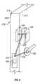
- FIG. 1illustrates an improved access control system with control line shield for a wireless access control system according to a preferred embodiment of the present invention.
- FIG. 2illustrates a perspective view of the installation of the wireless access control system according to a preferred embodiment of the present invention.
- FIG. 3illustrates a side view of the installation of the wireless access control system according to a preferred embodiment of the present invention.
- FIG. 4illustrates a perspective view of an alternative embodiment of the installation of a wireless access control system.
- FIG. 1illustrates an improved wireless access control system 100 with control line shield 180 for a wireless access control system according to a preferred embodiment of the present invention.
- the wireless access control system 100includes an access reader control 105 , access control electronics 150 , a control line shield 180 , a reader control line shield 181 and an electric lock 190 .
- the access reader control 105includes one or more link indicators 110 , an override port 115 , and an access reader 120 .
- the access control electronics 150includes a transceiver 155 , an antenna 157 , a power supply 160 , which may be external, a control circuit 165 , an access/monitoring processor 170 , and a locking control circuit 175 .
- the lock 190includes a lock motor 195 .
- the power supply 160provides power to the access control system 100 including powering the transceiver 155 , the control circuit 165 , the locking control circuit 175 , the electric motor 195 , the access reader control 105 , and the access/monitoring processor 170 .
- the power supply 160may be an internal battery or other internal type of power supply. Alternatively, an external AC power supply may be employed.
- the transceiver 155is coupled to the antenna 157 to allow RF signals to be sent and received from the wireless access control system 100 to an external point.
- the control circuit 165sends and receives data from the access/monitoring processor 170 and the transceiver 155 . Additionally, the control circuit 165 regulates the power supplied to the access reader control 105 by the power supply 160 .
- the access/monitoring processor 170sends signals to and receives signals from the control circuit 165 and the access reader 120 and sends signals to and receives signals from the locking control circuit 175 .
- the access/monitoring processor 170receives power from the control circuit 165 .
- the access/monitoring processor 170in turn powers the link indicators 110 , locking control circuit 175 , override port 115 , and access reader 120 .
- the access/monitoring processor 170additionally controls the link indicators 110 and receives data from the access reader 120 as well as the override ports 115 .
- the access/monitoring processor 170also sends commands to the locking control circuit 175 and receives data from the locking control circuit 175 .
- the link indicators 110may be a graphical or audible signal that the wireless access control system 100 has read an access signal, transmitted the access signal to the remote access control panel, received a confirmation, or activated the locking member, for example.
- the override port 115may be used, for example, by a technician to provide service or power to the wireless access control system.
- the access reader 120may read access information to aid in determining whether access should be granted.
- the access informationmay be of any type, but is preferably a biometric, proximity, magstripe or similar identifier.
- the lock motor 195may be of any type and may control a locking bar or other security device, for example.
- the locking control circuit 175is coupled to and provides control for the lock motor 195 .
- the coupling between the locking control circuit 175 and the lock motor 195is protected by a control line shield 180 which serves to reduce access to the control line between the locking control circuit 175 and the lock motor 195 .
- the control line shield 180may, for example, be a physical shield that limits access to the control line, such as a metal plate or a pre-formed housing within a door.
- an access signalmay be received from the access reader 120 .
- the access signalis then relayed to the access/monitoring processor 170 .
- the access/monitoring processor 170then sends the access signal to control circuit 165 which passes the signal to the transceiver 155 .
- the transceiver 155transmits the access signal to a database of authorized access signals (e.g., an access control panel). If the correct access data is in the database, a confirmation is transmitted to the transceiver 155 .
- the confirmationis relayed from the transceiver 155 to the access/monitoring processor 170 through the control circuit 165 .
- the access/monitoring processor 170then sends a control signal to the locking control circuit 175 .
- the locking control circuit 175activates the lock motor 195 to allow access.
- the connecting line between the locking control circuit 175 to the lock motor 195is protected by the control line shield 180 .
- the power supply 160is not contained within the access reader control 105 , and the access reader control 105 receives power from the power supply 160 via a link that provides power and communications between the access reader control 105 and the access control electronics 150 .
- the power supply 160may be included as part of the access reader control 105 .
- any or all of the functionality of the access control electronics 150may be integrated with the access reader control 105 .
- the wiringis shown as running between the access reader control 105 and the access control electronics 150 separately from the wiring running between the external lock 190 and the access control electronics 150 .
- the wiring between the access reader control 105 and the access control electronics 150is protected by a reader line shield 181 .
- the reader line shield 181serves to limit access to the wiring to reduce undesired tampering with the system.
- the reader line shieldmay be the door itself as the wiring between the access reader control 105 and the access control electronics passes through the door.
- the wiringmay run from the access control electronics 150 to the access reader control 105 to the external lock.
- the control line shield 180is configured to protect the wiring from the access reader control 105 to the external lock 195 .
- both the access reader control 105 and the access control electronics 150may be wired to the external lock 190 . In this instance, the control line shield 180 protects both sets of wiring.
- FIG. 2illustrates an installation 200 of the wireless access control system 100 according to a preferred embodiment of the present invention.
- the installation 200includes a door 210 , an access reader control 105 , access control electronics 150 , an external lock 190 and a control line shield embodied as an extended face plate 225 . Additionally, the door itself acts as a reader line shield between the access control reader 105 and the access control electronics 150 .
- the external lock 190includes a lock motor (not shown) that controls a latch 230 to lock or unlock the door 210 .
- the door 210includes a door front face 212 and a door edge 214 and a door back face 216 .
- the through-door channel 252serves to provide a passage for wiring connecting the access reader control 105 and the access control electronics 150 .
- the access reader control 105 and the access control electronics 150are connected by wiring running through the body of the door 210 perpendicular to the plane of the face of he door 210 .
- the wiring connecting the access reader control 105 and the access control electronics 150is thus typically safe from outside interference and tampering because is it concealed within the core of the door 210 .
- the access reader control 105 and/or access control electronics 150may be connected by wiring to the external lock 190 . That is, the through-door channel 252 intersects with the out-to-edge channel 254 to allow the passage of wiring out to the door edge 214 . At the door edge 214 , the wiring passes from the out-to-edge channel 254 to the along-edge channel 256 which is preferably inset into the face of the door edge 214 . The wiring then passes from the along-edge channel 256 to the in-to-lock channel 258 and then to the electric lock 190 .
- the wiringpreferably runs substantially perpendicular to the door face 212 through channel 252 then parallel to the door face 212 and to the door edge 214 .
- the wiringthen preferably runs along the door edge 214 downward to the height of the lock and then preferably runs from the door edge 214 inward substantially parallel to the door face 212 to the external lock 190 .
- the wiring that runs along the door edge 214is protected by a control line shield, in this case and extended face plate 225 .
- the extended face plate 225differs from the standard face plate because the extended face plate 225 has been increased in the vertical dimension, as compared to a standard faceplate, to protect the wiring running along the door edge 214 .
- the edge of the dooris modified to provide a recess into which the wiring and the face plate 225 may be fitted.
- the face plate 225is preferably flush with the edge of the door.
- the extended faceplate 225 in this caseis the control line shield 180 .
- control line shield 180helps to keep the control line that runs from the access reader control 105 to the electric lock 190 safe from outside interference and tampering.
- the control line shield 180seals the control line into the interior of the door to prevent easy access. Additionally, the control line shield 180 may be removed as necessary to provide service to the wireless access control system 100 .
- control line shield 180may take the form of two separate face plates, a first face plate that is standard for the lock 190 and an additional extension face plate. The extension face plate then extends from the top of the standard face plate to cover the additional vertical run of the wiring.
- FIG. 3illustrates a side view of the installation of the access control system according to a preferred embodiment of the present invention.
- the access reader control 105 and the access control electronics 150may be wired together through the through-door channel 252 . Wiring may then be drawn from either the access reader control 105 or the access control electronics 150 through the through-door channel 252 and then through the out-to-edge channel 254 to the door edge 214 . The wiring may then pass along the door edge 214 in the along-edge channel 256 to the in-to-lock channel 258 to the electric lock 190 .
- FIG. 4illustrates a perspective view of an alternative embodiment of the installation of the access control system.
- FIG. 4includes the access reader control 105 , access control electronics 150 and electric lock 190 with latch 230 installed in the door 210 which includes the door front face 212 , the door edge 214 and the door back face 216 .
- FIG. 4also includes the through-door channel 252 and in-to-lock channel 258 .
- FIG. 4includes a standard faceplate 410 .
- FIG. 4includes a single slope-to-edge channel 420 .
- system FIG. 4performs similarly to the system FIGS. 2-3 , except that the single slope-to-edge channel 420 eliminates the need for the out-to-edge channel 254 and the along-edge channel 256 . Additionally, the slope-to-edge channel 420 preferably emerges at the door edge 214 behind the faceplate 410 .
- the faceplate 410is typically a standard faceplate such as may have been previously installed in the door 210 . Thus, the extended faceplate 225 is not necessary to prevent access to the control line and the standard faceplate performs as the control line shield 180 .
- the embodiment of FIG. 4may be less preferable because the slope-to-edge channel 420 may be difficult to form or may compromise the integrity of the door or may be difficult to service. Conversely, the embodiment of FIG. 4 may be more preferable in instances when less modification to the door edge 214 is desired.
- a the channelmay be a hole or passage formed from the access reader control 105 or access control electronics 150 downward directly to the electric lock 190 through the door 210 .
- a hole or passagemay be exceedingly difficult to form and may significantly compromise the integrity of the door, as well as being difficult to service.
Landscapes
- Physics & Mathematics (AREA)
- General Physics & Mathematics (AREA)
- Engineering & Computer Science (AREA)
- Computer Networks & Wireless Communication (AREA)
- Lock And Its Accessories (AREA)
Abstract
Description
Claims (19)
Priority Applications (1)
| Application Number | Priority Date | Filing Date | Title |
|---|---|---|---|
| US10/887,619US7526934B2 (en) | 2001-09-30 | 2004-07-09 | Door wireless access control system including reader, lock, and wireless access control electronics including wireless transceiver |
Applications Claiming Priority (3)
| Application Number | Priority Date | Filing Date | Title |
|---|---|---|---|
| US32617901P | 2001-09-30 | 2001-09-30 | |
| US10/193,513US20030074936A1 (en) | 2001-09-30 | 2002-07-11 | Door wireless access control system including reader, lock, and wireless access control electronics including wireless transceiver |
| US10/887,619US7526934B2 (en) | 2001-09-30 | 2004-07-09 | Door wireless access control system including reader, lock, and wireless access control electronics including wireless transceiver |
Related Parent Applications (1)
| Application Number | Title | Priority Date | Filing Date |
|---|---|---|---|
| US10/193,513ContinuationUS20030074936A1 (en) | 2001-09-30 | 2002-07-11 | Door wireless access control system including reader, lock, and wireless access control electronics including wireless transceiver |
Publications (2)
| Publication Number | Publication Date |
|---|---|
| US20040261478A1 US20040261478A1 (en) | 2004-12-30 |
| US7526934B2true US7526934B2 (en) | 2009-05-05 |
Family
ID=26889074
Family Applications (2)
| Application Number | Title | Priority Date | Filing Date |
|---|---|---|---|
| US10/193,513AbandonedUS20030074936A1 (en) | 2001-09-30 | 2002-07-11 | Door wireless access control system including reader, lock, and wireless access control electronics including wireless transceiver |
| US10/887,619Expired - LifetimeUS7526934B2 (en) | 2001-09-30 | 2004-07-09 | Door wireless access control system including reader, lock, and wireless access control electronics including wireless transceiver |
Family Applications Before (1)
| Application Number | Title | Priority Date | Filing Date |
|---|---|---|---|
| US10/193,513AbandonedUS20030074936A1 (en) | 2001-09-30 | 2002-07-11 | Door wireless access control system including reader, lock, and wireless access control electronics including wireless transceiver |
Country Status (1)
| Country | Link |
|---|---|
| US (2) | US20030074936A1 (en) |
Cited By (16)
| Publication number | Priority date | Publication date | Assignee | Title |
|---|---|---|---|---|
| US20050164749A1 (en)* | 2004-01-20 | 2005-07-28 | Harrow Products Llc | Wireless access control system with energy-saving piezo-electric locking |
| US20120326851A1 (en)* | 2011-06-23 | 2012-12-27 | Sony Corporation | Remote control device, a far-end device, a multimedia system and a control method thereof |
| US8674832B1 (en) | 2010-06-25 | 2014-03-18 | Tregnel Kynta Thomas | Wireless bolt lock remote |
| US20160014131A1 (en)* | 2014-07-10 | 2016-01-14 | Schlage Lock Company Llc | Networked access control system |
| US9642089B2 (en) | 2008-07-09 | 2017-05-02 | Secureall Corporation | Method and system for planar, multi-function, multi-power sourced, long battery life radio communication appliance |
| CN107842252A (en)* | 2016-09-21 | 2018-03-27 | 古哲明 | Remote-controlled door lock assembly |
| US10089811B2 (en) | 2011-03-08 | 2018-10-02 | Security Enhancement Systems, Llc | Lock |
| US10128893B2 (en) | 2008-07-09 | 2018-11-13 | Secureall Corporation | Method and system for planar, multi-function, multi-power sourced, long battery life radio communication appliance |
| US10447334B2 (en) | 2008-07-09 | 2019-10-15 | Secureall Corporation | Methods and systems for comprehensive security-lockdown |
| US10743694B2 (en) | 2018-05-17 | 2020-08-18 | Securum Capsa, Inc. | Package receiving locker |
| US10985909B2 (en)* | 2007-09-27 | 2021-04-20 | Clevx, Llc | Door lock control with wireless user authentication |
| US11109705B2 (en) | 2018-09-26 | 2021-09-07 | Securum Capsa, Inc. | Medication receiver |
| US11151231B2 (en) | 2007-09-27 | 2021-10-19 | Clevx, Llc | Secure access device with dual authentication |
| US11190936B2 (en) | 2007-09-27 | 2021-11-30 | Clevx, Llc | Wireless authentication system |
| US11469789B2 (en) | 2008-07-09 | 2022-10-11 | Secureall Corporation | Methods and systems for comprehensive security-lockdown |
| US11639617B1 (en) | 2019-04-03 | 2023-05-02 | The Chamberlain Group Llc | Access control system and method |
Families Citing this family (15)
| Publication number | Priority date | Publication date | Assignee | Title |
|---|---|---|---|---|
| WO2005073929A1 (en)* | 2004-01-20 | 2005-08-11 | Harrow Products Llc | Access control system with energy-saving optical token presence sensor system |
| WO2007092623A2 (en)* | 2006-02-09 | 2007-08-16 | Bnw Investments, Llc | Multiple wireless access points for wireless locksets |
| US7818783B2 (en)* | 2006-03-08 | 2010-10-19 | Davis Russell J | System and method for global access control |
| US7690230B2 (en) | 2006-09-26 | 2010-04-06 | Yake Security Inc. | Housing for electronic lock |
| US8203426B1 (en) | 2007-07-11 | 2012-06-19 | Precision Edge Access Control, Inc. | Feed protocol used to report status and event information in physical access control system |
| US7967197B2 (en)* | 2007-07-24 | 2011-06-28 | Honeywell International Inc. | Integrated online door via electronic door handle |
| US8009013B1 (en)* | 2007-09-21 | 2011-08-30 | Precision Control Systems of Chicago, Inc. | Access control system and method using user location information for controlling access to a restricted area |
| FR2949268B1 (en)* | 2009-08-20 | 2012-09-28 | Radio Systemes Ingenierie Video Technologies | DEVICE FOR DETECTION OF ENTRY AND RECOGNITION OF TRANSPONDER BADGES, MONITORING SYSTEM COMPRISING SAME, AND SURVEILLANCE METHOD USED THEREBY |
| CN102945576A (en)* | 2012-11-19 | 2013-02-27 | 无锡商业职业技术学院 | Hospital visiting system |
| US20140260452A1 (en)* | 2013-03-14 | 2014-09-18 | Hsu-Chih CHEN | Electronic Lock |
| EP2973208A2 (en)* | 2013-03-15 | 2016-01-20 | Assa Abloy Ab | Tamper credential |
| DE102014201130A1 (en)* | 2014-01-22 | 2015-07-23 | Robert Bosch Gmbh | Method and device for determining an unauthorized intrusion on a door |
| CN104537747B (en)* | 2015-01-17 | 2016-09-28 | 郑玉龙 | Remote control door bolt alarm |
| CN107886612A (en)* | 2017-12-13 | 2018-04-06 | 太仓鼎诚电子科技有限公司 | A kind of wireless access control system based on RFID technique |
| TWI651458B (en)* | 2018-01-04 | 2019-02-21 | 台灣福興工業股份有限公司 | Electronic lock and its control method |
Citations (69)
| Publication number | Priority date | Publication date | Assignee | Title |
|---|---|---|---|---|
| US306806A (en) | 1884-10-21 | Door-protector | ||
| US528589A (en) | 1894-11-06 | And james | ||
| US1946384A (en) | 1933-02-16 | 1934-02-06 | Lucien R Baril | Electric lock |
| US3967478A (en)* | 1975-06-09 | 1976-07-06 | Guinn Stanley G | Door latching apparatus actuated by cleansing agent sensor |
| US4048630A (en) | 1976-01-22 | 1977-09-13 | The Alliance Manufacturing Co., Inc. | Door operator with automatic control of auxiliary circuit |
| US4397168A (en)* | 1980-04-18 | 1983-08-09 | Tre Corporation | Door reinforcement and lock guard plate |
| US4539555A (en) | 1982-12-09 | 1985-09-03 | Tefka Edward E | Fire and smoke protection device for use in buildings |
| US4557121A (en) | 1983-08-22 | 1985-12-10 | Security Engineering, Inc. | Electric fail-secure/fail-open lock mechanism |
| US4579376A (en) | 1984-03-14 | 1986-04-01 | Security Engineering, Inc. | Fail-secure and fail-safe door lock mechanism |
| US4634155A (en) | 1983-09-01 | 1987-01-06 | Geringer Arthur V | Power actuated door locking and monitoring assembly |
| US4677834A (en) | 1985-08-07 | 1987-07-07 | Hicks Cecil B | Electro-mechanical security lock |
| USD306806S (en) | 1987-04-27 | 1990-03-27 | Masco Corporation Of Indiana | Faucet display stand |
| US4967478A (en) | 1989-03-20 | 1990-11-06 | Sherman Bradley G | Perspective bow sight |
| US5009456A (en) | 1989-02-10 | 1991-04-23 | Lasinvast Svenska Ab | Door lock apparatus |
| US5095654A (en)* | 1990-07-30 | 1992-03-17 | Eccleston Jon E | Automatic operating system for swinging door |
| US5148691A (en) | 1989-06-29 | 1992-09-22 | Assa Ab | Electrically and mechanically activatable lock mechanism |
| US5263347A (en) | 1992-09-21 | 1993-11-23 | Allbaugh Mark E | Remote control deadlock bolt for cars |
| US5308131A (en) | 1993-03-26 | 1994-05-03 | Schlage Lock Company | Interchangeable faceplates for door latches permitting adaptation to a variety of standard door preparations |
| US5313812A (en) | 1992-09-11 | 1994-05-24 | Eklund Sigurd T | Door lock security system |
| US5410444A (en) | 1992-10-27 | 1995-04-25 | Idx, Inc. | Electronic control system for a locked drawer |
| US5475375A (en) | 1985-10-16 | 1995-12-12 | Supra Products, Inc. | Electronic access control systems |
| US5479151A (en) | 1994-03-31 | 1995-12-26 | Harrow Products, Inc. | Electromagnetic door lock with on-board programmable access control |
| US5531086A (en) | 1994-08-15 | 1996-07-02 | Bryant; Randy K. | Keyless entry deadbolt lock |
| US5602536A (en) | 1985-10-16 | 1997-02-11 | Supra Products, Inc. | Data synchronization method for use with portable, microprocessor-based device |
| US5608298A (en) | 1994-07-14 | 1997-03-04 | Harrow Products, Inc. | Privacy protection for electronic lock system |
| US5611582A (en) | 1996-03-28 | 1997-03-18 | Harrow Products, Inc. | Impact resistant armature |
| US5630169A (en) | 1992-09-24 | 1997-05-13 | Unisys Corporation | Apparatus for a host central processor with associated controller to capture a selected one of a number of memory units via path control commands |
| US5682135A (en) | 1995-05-04 | 1997-10-28 | Kiekert Ag | Motor vehicle security system |
| US5683127A (en) | 1994-11-04 | 1997-11-04 | Schlage Lock Company | Deadbolt latch assembly |
| FR2749607A1 (en) | 1996-06-10 | 1997-12-12 | Valeo Electronique | Unlocking security system for cars |
| US5705991A (en) | 1992-01-09 | 1998-01-06 | Supra Products, Inc. | Access control device featuring key ordering or key simultaneity |
| US5722276A (en) | 1995-08-03 | 1998-03-03 | Schlage Lock Company | Method for attaching faceplate mounting tabs to a mortise lock housing and tabs and housings adapted for that method |
| US5729198A (en) | 1996-10-25 | 1998-03-17 | Gorman; Kim Ramsey | Wireless residential door unlatch system |
| US5769472A (en) | 1996-12-30 | 1998-06-23 | Schlage Lock Company | Drive in housing halves for mounting a latch assembly in a door and a method of installing same |
| US5791178A (en) | 1995-12-26 | 1998-08-11 | Schlage Lock Company | Electrical transmission path for electrical and electro-mechanical locks |
| USD397993S (en) | 1996-07-26 | 1998-09-08 | Schlage Lock Company | Cover for door lock electronics and battery |
| US5808296A (en) | 1996-03-22 | 1998-09-15 | Banner Engineering Corporation | Programmable detection sensor with means to automatically adjust sensor operating characteristics to optimize performance for both high gain and low contrast applications |
| US5881055A (en) | 1995-11-14 | 1999-03-09 | Sharp Kabushiki Kaisha | Battery saving synchronization method in a communcation apparatus |
| US5933086A (en) | 1991-09-19 | 1999-08-03 | Schlage Lock Company | Remotely-operated self-contained electronic lock security system assembly |
| US5936544A (en) | 1997-09-30 | 1999-08-10 | Pittway Corporation | Wireless access system |
| US5940771A (en) | 1991-05-13 | 1999-08-17 | Norand Corporation | Network supporting roaming, sleeping terminals |
| US6021477A (en) | 1989-05-05 | 2000-02-01 | Samsung Electronics Co., Ltd | Multiple mode memory module |
| US6035676A (en) | 1997-06-02 | 2000-03-14 | Hudspeth; Chad W. | System for remote operation of a deadbolt lock |
| US6038896A (en) | 1996-07-16 | 2000-03-21 | Schlage Lock Company | Lockset with motorized system for locking and unlocking |
| US6067297A (en) | 1996-06-28 | 2000-05-23 | Symbol Technologies, Inc. | Embedded access point supporting communication with mobile unit operating in power-saving mode |
| US6076385A (en) | 1998-08-05 | 2000-06-20 | Innovative Industries, Corporation | Security door lock with remote control |
| US6108188A (en) | 1999-01-15 | 2000-08-22 | Micro Enhanced Technology | Electronic locking system with an access-control solenoid |
| US6108108A (en) | 1998-03-20 | 2000-08-22 | Silitek Corporation | Platen type scanner driving mechanism (1) |
| US6167934B1 (en) | 1996-11-27 | 2001-01-02 | Sedepro | Removable thread guide which receives threads projected onto a surface |
| US6189351B1 (en) | 1997-01-27 | 2001-02-20 | Schlage Lock Company | Door lock with clutching mechanism |
| US6212175B1 (en) | 1997-04-22 | 2001-04-03 | Telxon Corporation | Method to sustain TCP connection |
| US6259352B1 (en)* | 1998-03-02 | 2001-07-10 | Leon Yulkowski | Door lock system |
| US6285295B1 (en) | 1998-12-14 | 2001-09-04 | Martin S. Casden | Passive remote programmer for induction type RFID readers |
| US6330817B1 (en) | 2000-02-01 | 2001-12-18 | Harrow Products, Inc. | Anti-jam locking mechanism for electronic security system |
| US6347486B1 (en)* | 1998-11-02 | 2002-02-19 | Unitechniques | Apparatus for controlling the opening of a door |
| WO2002025040A1 (en) | 2000-09-22 | 2002-03-28 | Australian Arrow Pty Ltd | Proximity activated entry system |
| US6397061B1 (en) | 2000-06-24 | 2002-05-28 | Motorola, Inc. | Method and apparatus to reprioritize data transfer in a short range Ad Hoc network |
| USRE37784E1 (en)* | 1995-05-17 | 2002-07-09 | The Chamberlain Group, Inc. | Barrier operator having system for detecting attempted forced entry |
| US6434985B1 (en)* | 2001-05-30 | 2002-08-20 | Exodus Innovations Pty Limited | Security grille locking system |
| US6486793B1 (en)* | 1999-10-25 | 2002-11-26 | Alarm Lock Systems, Inc. | Wireless magnetic lock control system |
| US20020177473A1 (en) | 2001-05-25 | 2002-11-28 | Palm, Inc. | Wireless transaction enabled handheld computer system and method |
| US20020180582A1 (en) | 1999-11-30 | 2002-12-05 | Nielsen Ernst Lykke | Electronic key device a system and a method of managing electronic key information |
| US20030025082A1 (en) | 2001-08-02 | 2003-02-06 | International Business Machines Corporation | Active infrared presence sensor |
| US6665520B2 (en) | 1997-10-03 | 2003-12-16 | Hewlett-Packard Development Company, L.C. | Power management method of and apparatus for use in a wireless local area network (LAN) |
| US6679019B2 (en)* | 2001-01-16 | 2004-01-20 | Rochman Universal Doors, Inc. | Method and apparatus for reinforcing a door |
| US6714118B1 (en)* | 2000-05-08 | 2004-03-30 | Harrow Products, Inc. | Modular electronic door security system |
| US6828902B2 (en) | 1998-12-14 | 2004-12-07 | Soundcraft, Inc. | Wireless data input to RFID reader |
| US6879259B1 (en) | 2001-03-30 | 2005-04-12 | Bellsouth Intellectual Property Corporation | Battery voltage indicator in a portable computing device |
| US6958976B2 (en) | 2000-07-27 | 2005-10-25 | Denso Corporation | Abnormality detection method and system having sleep mode check function |
Family Cites Families (2)
| Publication number | Priority date | Publication date | Assignee | Title |
|---|---|---|---|---|
| US4832388A (en)* | 1986-03-14 | 1989-05-23 | Lozano Anthony R | Door assembly and components thereof applicable to increase resistance to forced entry |
| DE69811625T2 (en)* | 1998-01-16 | 2003-10-23 | Fuji Photo Film Co. Ltd., Minamiashigara | Heat-sensitive recording material |
- 2002
- 2002-07-11USUS10/193,513patent/US20030074936A1/ennot_activeAbandoned
- 2004
- 2004-07-09USUS10/887,619patent/US7526934B2/ennot_activeExpired - Lifetime
Patent Citations (70)
| Publication number | Priority date | Publication date | Assignee | Title |
|---|---|---|---|---|
| US306806A (en) | 1884-10-21 | Door-protector | ||
| US528589A (en) | 1894-11-06 | And james | ||
| US1946384A (en) | 1933-02-16 | 1934-02-06 | Lucien R Baril | Electric lock |
| US3967478A (en)* | 1975-06-09 | 1976-07-06 | Guinn Stanley G | Door latching apparatus actuated by cleansing agent sensor |
| US4048630A (en) | 1976-01-22 | 1977-09-13 | The Alliance Manufacturing Co., Inc. | Door operator with automatic control of auxiliary circuit |
| US4397168A (en)* | 1980-04-18 | 1983-08-09 | Tre Corporation | Door reinforcement and lock guard plate |
| US4539555A (en) | 1982-12-09 | 1985-09-03 | Tefka Edward E | Fire and smoke protection device for use in buildings |
| US4557121A (en) | 1983-08-22 | 1985-12-10 | Security Engineering, Inc. | Electric fail-secure/fail-open lock mechanism |
| US4634155A (en) | 1983-09-01 | 1987-01-06 | Geringer Arthur V | Power actuated door locking and monitoring assembly |
| US4579376A (en) | 1984-03-14 | 1986-04-01 | Security Engineering, Inc. | Fail-secure and fail-safe door lock mechanism |
| US4677834A (en) | 1985-08-07 | 1987-07-07 | Hicks Cecil B | Electro-mechanical security lock |
| US5475375A (en) | 1985-10-16 | 1995-12-12 | Supra Products, Inc. | Electronic access control systems |
| US5602536A (en) | 1985-10-16 | 1997-02-11 | Supra Products, Inc. | Data synchronization method for use with portable, microprocessor-based device |
| USD306806S (en) | 1987-04-27 | 1990-03-27 | Masco Corporation Of Indiana | Faucet display stand |
| US5009456A (en) | 1989-02-10 | 1991-04-23 | Lasinvast Svenska Ab | Door lock apparatus |
| US4967478A (en) | 1989-03-20 | 1990-11-06 | Sherman Bradley G | Perspective bow sight |
| US6021477A (en) | 1989-05-05 | 2000-02-01 | Samsung Electronics Co., Ltd | Multiple mode memory module |
| US5148691A (en) | 1989-06-29 | 1992-09-22 | Assa Ab | Electrically and mechanically activatable lock mechanism |
| US5095654A (en)* | 1990-07-30 | 1992-03-17 | Eccleston Jon E | Automatic operating system for swinging door |
| US5940771A (en) | 1991-05-13 | 1999-08-17 | Norand Corporation | Network supporting roaming, sleeping terminals |
| US5933086A (en) | 1991-09-19 | 1999-08-03 | Schlage Lock Company | Remotely-operated self-contained electronic lock security system assembly |
| US6297725B1 (en) | 1991-09-19 | 2001-10-02 | Schlage Lock Company | Remotely-operated self-contained electronic lock security system assembly |
| US5705991A (en) | 1992-01-09 | 1998-01-06 | Supra Products, Inc. | Access control device featuring key ordering or key simultaneity |
| US5313812A (en) | 1992-09-11 | 1994-05-24 | Eklund Sigurd T | Door lock security system |
| US5263347A (en) | 1992-09-21 | 1993-11-23 | Allbaugh Mark E | Remote control deadlock bolt for cars |
| US5630169A (en) | 1992-09-24 | 1997-05-13 | Unisys Corporation | Apparatus for a host central processor with associated controller to capture a selected one of a number of memory units via path control commands |
| US5410444A (en) | 1992-10-27 | 1995-04-25 | Idx, Inc. | Electronic control system for a locked drawer |
| US5308131A (en) | 1993-03-26 | 1994-05-03 | Schlage Lock Company | Interchangeable faceplates for door latches permitting adaptation to a variety of standard door preparations |
| US5479151A (en) | 1994-03-31 | 1995-12-26 | Harrow Products, Inc. | Electromagnetic door lock with on-board programmable access control |
| US5608298A (en) | 1994-07-14 | 1997-03-04 | Harrow Products, Inc. | Privacy protection for electronic lock system |
| US5531086A (en) | 1994-08-15 | 1996-07-02 | Bryant; Randy K. | Keyless entry deadbolt lock |
| US5683127A (en) | 1994-11-04 | 1997-11-04 | Schlage Lock Company | Deadbolt latch assembly |
| US5682135A (en) | 1995-05-04 | 1997-10-28 | Kiekert Ag | Motor vehicle security system |
| USRE37784E1 (en)* | 1995-05-17 | 2002-07-09 | The Chamberlain Group, Inc. | Barrier operator having system for detecting attempted forced entry |
| US5722276A (en) | 1995-08-03 | 1998-03-03 | Schlage Lock Company | Method for attaching faceplate mounting tabs to a mortise lock housing and tabs and housings adapted for that method |
| US5881055A (en) | 1995-11-14 | 1999-03-09 | Sharp Kabushiki Kaisha | Battery saving synchronization method in a communcation apparatus |
| US5791178A (en) | 1995-12-26 | 1998-08-11 | Schlage Lock Company | Electrical transmission path for electrical and electro-mechanical locks |
| US5808296A (en) | 1996-03-22 | 1998-09-15 | Banner Engineering Corporation | Programmable detection sensor with means to automatically adjust sensor operating characteristics to optimize performance for both high gain and low contrast applications |
| US5611582A (en) | 1996-03-28 | 1997-03-18 | Harrow Products, Inc. | Impact resistant armature |
| FR2749607A1 (en) | 1996-06-10 | 1997-12-12 | Valeo Electronique | Unlocking security system for cars |
| US6067297A (en) | 1996-06-28 | 2000-05-23 | Symbol Technologies, Inc. | Embedded access point supporting communication with mobile unit operating in power-saving mode |
| US6038896A (en) | 1996-07-16 | 2000-03-21 | Schlage Lock Company | Lockset with motorized system for locking and unlocking |
| USD397993S (en) | 1996-07-26 | 1998-09-08 | Schlage Lock Company | Cover for door lock electronics and battery |
| US5729198A (en) | 1996-10-25 | 1998-03-17 | Gorman; Kim Ramsey | Wireless residential door unlatch system |
| US6167934B1 (en) | 1996-11-27 | 2001-01-02 | Sedepro | Removable thread guide which receives threads projected onto a surface |
| US5769472A (en) | 1996-12-30 | 1998-06-23 | Schlage Lock Company | Drive in housing halves for mounting a latch assembly in a door and a method of installing same |
| US6189351B1 (en) | 1997-01-27 | 2001-02-20 | Schlage Lock Company | Door lock with clutching mechanism |
| US6212175B1 (en) | 1997-04-22 | 2001-04-03 | Telxon Corporation | Method to sustain TCP connection |
| US6035676A (en) | 1997-06-02 | 2000-03-14 | Hudspeth; Chad W. | System for remote operation of a deadbolt lock |
| US5936544A (en) | 1997-09-30 | 1999-08-10 | Pittway Corporation | Wireless access system |
| US6665520B2 (en) | 1997-10-03 | 2003-12-16 | Hewlett-Packard Development Company, L.C. | Power management method of and apparatus for use in a wireless local area network (LAN) |
| US6259352B1 (en)* | 1998-03-02 | 2001-07-10 | Leon Yulkowski | Door lock system |
| US6108108A (en) | 1998-03-20 | 2000-08-22 | Silitek Corporation | Platen type scanner driving mechanism (1) |
| US6076385A (en) | 1998-08-05 | 2000-06-20 | Innovative Industries, Corporation | Security door lock with remote control |
| US6347486B1 (en)* | 1998-11-02 | 2002-02-19 | Unitechniques | Apparatus for controlling the opening of a door |
| US6285295B1 (en) | 1998-12-14 | 2001-09-04 | Martin S. Casden | Passive remote programmer for induction type RFID readers |
| US6828902B2 (en) | 1998-12-14 | 2004-12-07 | Soundcraft, Inc. | Wireless data input to RFID reader |
| US6108188A (en) | 1999-01-15 | 2000-08-22 | Micro Enhanced Technology | Electronic locking system with an access-control solenoid |
| US6486793B1 (en)* | 1999-10-25 | 2002-11-26 | Alarm Lock Systems, Inc. | Wireless magnetic lock control system |
| US20020180582A1 (en) | 1999-11-30 | 2002-12-05 | Nielsen Ernst Lykke | Electronic key device a system and a method of managing electronic key information |
| US6330817B1 (en) | 2000-02-01 | 2001-12-18 | Harrow Products, Inc. | Anti-jam locking mechanism for electronic security system |
| US6714118B1 (en)* | 2000-05-08 | 2004-03-30 | Harrow Products, Inc. | Modular electronic door security system |
| US6397061B1 (en) | 2000-06-24 | 2002-05-28 | Motorola, Inc. | Method and apparatus to reprioritize data transfer in a short range Ad Hoc network |
| US6958976B2 (en) | 2000-07-27 | 2005-10-25 | Denso Corporation | Abnormality detection method and system having sleep mode check function |
| WO2002025040A1 (en) | 2000-09-22 | 2002-03-28 | Australian Arrow Pty Ltd | Proximity activated entry system |
| US6679019B2 (en)* | 2001-01-16 | 2004-01-20 | Rochman Universal Doors, Inc. | Method and apparatus for reinforcing a door |
| US6879259B1 (en) | 2001-03-30 | 2005-04-12 | Bellsouth Intellectual Property Corporation | Battery voltage indicator in a portable computing device |
| US20020177473A1 (en) | 2001-05-25 | 2002-11-28 | Palm, Inc. | Wireless transaction enabled handheld computer system and method |
| US6434985B1 (en)* | 2001-05-30 | 2002-08-20 | Exodus Innovations Pty Limited | Security grille locking system |
| US20030025082A1 (en) | 2001-08-02 | 2003-02-06 | International Business Machines Corporation | Active infrared presence sensor |
Cited By (27)
| Publication number | Priority date | Publication date | Assignee | Title |
|---|---|---|---|---|
| US7747286B2 (en)* | 2004-01-20 | 2010-06-29 | Harrow Products Llc | Wireless access control system with energy-saving piezo-electric locking |
| US20050164749A1 (en)* | 2004-01-20 | 2005-07-28 | Harrow Products Llc | Wireless access control system with energy-saving piezo-electric locking |
| US10985909B2 (en)* | 2007-09-27 | 2021-04-20 | Clevx, Llc | Door lock control with wireless user authentication |
| US11151231B2 (en) | 2007-09-27 | 2021-10-19 | Clevx, Llc | Secure access device with dual authentication |
| US11190936B2 (en) | 2007-09-27 | 2021-11-30 | Clevx, Llc | Wireless authentication system |
| US12437040B2 (en) | 2007-09-27 | 2025-10-07 | Clevx, Llc | Secure access device with multiple authentication mechanisms |
| US11971967B2 (en) | 2007-09-27 | 2024-04-30 | Clevx, Llc | Secure access device with multiple authentication mechanisms |
| US11233630B2 (en) | 2007-09-27 | 2022-01-25 | Clevx, Llc | Module with embedded wireless user authentication |
| US9642089B2 (en) | 2008-07-09 | 2017-05-02 | Secureall Corporation | Method and system for planar, multi-function, multi-power sourced, long battery life radio communication appliance |
| US11469789B2 (en) | 2008-07-09 | 2022-10-11 | Secureall Corporation | Methods and systems for comprehensive security-lockdown |
| US10128893B2 (en) | 2008-07-09 | 2018-11-13 | Secureall Corporation | Method and system for planar, multi-function, multi-power sourced, long battery life radio communication appliance |
| US10447334B2 (en) | 2008-07-09 | 2019-10-15 | Secureall Corporation | Methods and systems for comprehensive security-lockdown |
| US8674832B1 (en) | 2010-06-25 | 2014-03-18 | Tregnel Kynta Thomas | Wireless bolt lock remote |
| US10089811B2 (en) | 2011-03-08 | 2018-10-02 | Security Enhancement Systems, Llc | Lock |
| US9024734B2 (en)* | 2011-06-23 | 2015-05-05 | Sony Corporation | Remote control device, a far-end device, a multimedia system and a control method thereof |
| US20120326851A1 (en)* | 2011-06-23 | 2012-12-27 | Sony Corporation | Remote control device, a far-end device, a multimedia system and a control method thereof |
| US10122721B2 (en)* | 2014-07-10 | 2018-11-06 | Schlage Lock Company Llc | Networked access control system |
| US10574655B2 (en)* | 2014-07-10 | 2020-02-25 | Schlage Lock Company Llc | Networked access control system |
| US9787684B2 (en)* | 2014-07-10 | 2017-10-10 | Schlage Lock Company Llc | Networked access control system |
| US20170012777A1 (en)* | 2014-07-10 | 2017-01-12 | Schlage Lock Company Llc | Networked access control system |
| US9531721B2 (en)* | 2014-07-10 | 2016-12-27 | Schlage Lock Company Llc | Networked access control system |
| US20160014131A1 (en)* | 2014-07-10 | 2016-01-14 | Schlage Lock Company Llc | Networked access control system |
| CN107842252A (en)* | 2016-09-21 | 2018-03-27 | 古哲明 | Remote-controlled door lock assembly |
| US10743694B2 (en) | 2018-05-17 | 2020-08-18 | Securum Capsa, Inc. | Package receiving locker |
| US11399649B2 (en) | 2018-05-17 | 2022-08-02 | Securum Capsa, Inc. | Package receiving locker |
| US11109705B2 (en) | 2018-09-26 | 2021-09-07 | Securum Capsa, Inc. | Medication receiver |
| US11639617B1 (en) | 2019-04-03 | 2023-05-02 | The Chamberlain Group Llc | Access control system and method |
Also Published As
| Publication number | Publication date |
|---|---|
| US20040261478A1 (en) | 2004-12-30 |
| US20030074936A1 (en) | 2003-04-24 |
Similar Documents
| Publication | Publication Date | Title |
|---|---|---|
| US7526934B2 (en) | Door wireless access control system including reader, lock, and wireless access control electronics including wireless transceiver | |
| US5469727A (en) | Electronic lock cylinder | |
| US7967197B2 (en) | Integrated online door via electronic door handle | |
| EP2308030B1 (en) | Electronic door lock with modular components | |
| US6486793B1 (en) | Wireless magnetic lock control system | |
| US10017960B2 (en) | Key box | |
| US20140347163A1 (en) | Vehicle access system and controller therefor | |
| US20120218076A1 (en) | Wireless capable security door antenna | |
| US9911293B2 (en) | Security device for integration into a security system | |
| US20160017640A1 (en) | Electronic Door Locking System | |
| CN110080617B (en) | Digital key system | |
| JP4345219B2 (en) | Non-contact ID reader mounting structure, mounting method, removing method, manufacturing method, and electric lock system | |
| US20100201479A1 (en) | Integrated On-Line Door Control System with Standardized Interfaces | |
| US10553088B2 (en) | Security device for integration into a security system | |
| KR100728656B1 (en) | Digital door lock with control panel and lock separated | |
| CN212689832U (en) | Business library equipment | |
| CN218953047U (en) | Three-in-one anti-trailing linkage interlocking device | |
| JP2007316735A (en) | Admission management system | |
| KR200425566Y1 (en) | Electronic door locks for cages | |
| JP4964626B2 (en) | Authentication type key system reader | |
| CN107659657A (en) | A kind of intelligent access control system based on platform of internet of things | |
| KR20100070191A (en) | Digital door lock | |
| KR200378896Y1 (en) | Door Lock Apparatus Having Function for Preventing Insects | |
| KR20240036425A (en) | Electric charging door | |
| AU2024227783A1 (en) | Access Control Device and Housing |
Legal Events
| Date | Code | Title | Description |
|---|---|---|---|
| AS | Assignment | Owner name:HARROW PRODUCTS LLC, NEW JERSEY Free format text:ASSIGNMENT OF ASSIGNORS INTEREST;ASSIGNOR:RECOGNITION SOURCE, LLC;REEL/FRAME:015539/0041 Effective date:20040923 | |
| STCF | Information on status: patent grant | Free format text:PATENTED CASE | |
| FEPP | Fee payment procedure | Free format text:PAT HOLDER NO LONGER CLAIMS SMALL ENTITY STATUS, ENTITY STATUS SET TO UNDISCOUNTED (ORIGINAL EVENT CODE: STOL); ENTITY STATUS OF PATENT OWNER: LARGE ENTITY | |
| FPAY | Fee payment | Year of fee payment:4 | |
| AS | Assignment | Owner name:SCHLAGE LOCK COMPANY LLC, INDIANA Free format text:ASSIGNMENT OF ASSIGNORS INTEREST;ASSIGNOR:HARROW PRODUCTS LLC;REEL/FRAME:030982/0812 Effective date:20130805 | |
| AS | Assignment | Owner name:HARROW PRODUCTS LLC, INDIANA Free format text:CORRECTIVE ASSIGNMENT TO CORRECT THE ASSIGNEE FROM SCHLAGE LOCK COMPANY LLC TO HARROW PRODUCTS LLC PREVIOUSLY RECORDED ON REEL 030982 FRAME 0812. ASSIGNOR(S) HEREBY CONFIRMS THE ASSIGNMENT;ASSIGNOR:HARROW PRODUCTS LLC;REEL/FRAME:031478/0690 Effective date:20130805 | |
| AS | Assignment | Owner name:JPMORGAN CHASE BANK, N.A., AS ADMINISTRATIVE AGENT Free format text:SECURITY AGREEMENT;ASSIGNOR:SCHLAGE LOCK COMPANY LLC;REEL/FRAME:031831/0091 Effective date:20131126 | |
| AS | Assignment | Owner name:JPMORGAN CHASE BANK, N.A., AS ADMINISTRATIVE AGENT Free format text:SECURITY AGREEMENT;ASSIGNOR:SCHLAGE LOCK COMPANY LLC;REEL/FRAME:034173/0001 Effective date:20141015 | |
| FPAY | Fee payment | Year of fee payment:8 | |
| MAFP | Maintenance fee payment | Free format text:PAYMENT OF MAINTENANCE FEE, 12TH YEAR, LARGE ENTITY (ORIGINAL EVENT CODE: M1553); ENTITY STATUS OF PATENT OWNER: LARGE ENTITY Year of fee payment:12 |