US7525590B2 - Camera apparatus with exposure correction based on movement of the object - Google Patents
Camera apparatus with exposure correction based on movement of the objectDownload PDFInfo
- Publication number
- US7525590B2 US7525590B2US11/049,930US4993005AUS7525590B2US 7525590 B2US7525590 B2US 7525590B2US 4993005 AUS4993005 AUS 4993005AUS 7525590 B2US7525590 B2US 7525590B2
- Authority
- US
- United States
- Prior art keywords
- unit
- speed
- movement
- stop value
- camera apparatus
- Prior art date
- Legal status (The legal status is an assumption and is not a legal conclusion. Google has not performed a legal analysis and makes no representation as to the accuracy of the status listed.)
- Expired - Fee Related, expires
Links
- 238000003384imaging methodMethods0.000claimsabstractdescription26
- 239000013598vectorSubstances0.000description18
- 238000005070samplingMethods0.000description8
- 230000002596correlated effectEffects0.000description5
- 230000000875corresponding effectEffects0.000description5
- 230000001276controlling effectEffects0.000description4
- 238000000034methodMethods0.000description3
- 230000006835compressionEffects0.000description2
- 238000007906compressionMethods0.000description2
- 230000006870functionEffects0.000description2
- 238000007781pre-processingMethods0.000description2
- 238000010586diagramMethods0.000description1
- 238000005286illuminationMethods0.000description1
- 230000003287optical effectEffects0.000description1
- 238000000926separation methodMethods0.000description1
Images


Classifications
- H—ELECTRICITY
- H04—ELECTRIC COMMUNICATION TECHNIQUE
- H04N—PICTORIAL COMMUNICATION, e.g. TELEVISION
- H04N23/00—Cameras or camera modules comprising electronic image sensors; Control thereof
- H04N23/70—Circuitry for compensating brightness variation in the scene
- H04N23/73—Circuitry for compensating brightness variation in the scene by influencing the exposure time
Definitions
- the present inventionrelates to camera apparatuses such as an electronic still camera, a video camera, and a film camera.
- a camera apparatussuch as an electronic still camera generally has an auto exposure control (AE) function and an auto focus control (AF) function.
- AEauto exposure control
- AFauto focus control
- the shutter speed, the f-stop value, and the likeare adjusted on the basis of the EV value (brightness).
- the movement of the hands, the speed of movement of a subject, and so forthare not considered.
- the hands move or the speed of movement of the subjectis high, a proper image is not obtained.
- An object of the present inventionis to provide a camera apparatus in which a proper image is obtained even in cases such as a case where the hands move and a case where the speed of movement of a subject is high.
- a camera apparatusis characterized by comprising an imaging device, means for detecting information relating to the movement of an object on the basis of an output of the imaging device, and exposure correction means for making exposure correction on the basis of the detected information relating to the movement of the object.
- An example of the exposure correction meansis one for correcting the shutter speed on the basis of the detected information relating to the movement of the object.
- An example of the exposure correction meansis one for correcting the shutter speed and the diaphragm on the basis of the detected information relating to the movement of the object.
- An example of the exposure correction meansis one for correcting the shutter speed and the diaphragm as well as controlling the gain on the basis of the detected information relating to the movement of the object.
- An example of the exposure correction meansis one for correcting the shutter speed and the diaphragm as well as controlling the gain and the strobo flashing in a case where a shutter is released on the basis of the detected information relating to the movement of the object.
- An example of the information relating to the movement of the objectis motion vectors respectively corresponding to a plurality of detecting areas set in an imaging area of the imaging device.
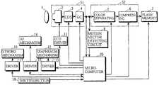
- FIG. 1is a block diagram showing the configuration of an electronic still camera
- FIG. 2is a schematic view showing a plurality of detecting areas set in an image area of an imaging device
- FIG. 3is a schematic view showing a plurality of small areas in the detecting area shown in FIG. 2 ;
- FIG. 4is a schematic view showing a plurality of sampling points and one representative point which are set in the small area shown in FIG. 3 ;
- FIG. 5is a flow chart showing the procedure for processing performed by a microcomputer.
- FIG. 1illustrates the configuration of an electronic still camera.
- reference numeral 1denotes an optical system
- reference numeral 2denotes a CCD (Charge Coupled Device) imaging device
- Reference numeral 3denotes a co-related double sampling (CDS) circuit, which is provided for removing noise peculiar to the CCD imaging device 2 from an output of the imaging device 2
- Reference numeral 4denotes a gain control (GC) circuit.
- the CCD imaging device 2 , the CDS circuit 3 and the GC circuit 4constitute a signal preprocessing unit 51 .
- Reference numeral 5denotes a color separating circuit, which produces a luminance signal Y and color difference signals Cr and Cb on the basis of an output of the GC circuit 4 .
- Reference numeral 6denotes a compressing circuit, which subjects the luminance signal Y and the color difference signals Cr and Cb to JPEG (Joint Photographic Experts Group) compression.
- the color separating circuit 5 and the compressing circuit 6constitute a main signal processing unit 52 .
- Reference numeral 7denotes a flash memory for recording compressed data.
- Reference numeral 8denotes a motion vector detecting circuit for detecting motion vectors for each frame on the basis of the output of the GC circuit 4 .
- Reference numeral 11denotes a CCD driver.
- Reference numeral 12denotes a diaphragm mechanism, and reference numeral 13 denotes its driver.
- Reference numeral 14denotes an AF mechanism for adjusting the position of a focusing lens, and reference numeral 15 denotes its driver.
- Reference numeral 16denotes a strobo mechanism, and reference numeral 17 denotes its driver.
- Reference numeral 18denotes a shutter button.
- Reference numeral 20denotes a microcomputer for controlling the above-mentioned devices.
- the motion vector detecting circuit 8detects for each frame motion vectors (information relating to the movement) for a plurality of detecting areas E set in an imaging area 100 of the imaging device 2 , as shown in FIG. 2 , on the basis of a representative point matching method.
- each of the detecting areas Eis further divided into a plurality of small areas e, as shown in FIG. 3 .
- a plurality of sampling points S and one representative point Rare set in each of the small areas e.
- the sum of correlated values at the sampling points S which are the same in deviation from the representative points R in all the small areas e in the detecting area Eis found (a value obtained is hereinafter referred to as an accumulated correlated value). Consequently, accumulated correlated values whose number corresponds to the number of the sampling points S in one of the small areas e are found for each of the detecting areas E.
- Deviation of the sampling point S having the minimum accumulated correlated value, that is, the highest correlation in each of the detecting areas Eis extracted as a motion vector (the movement of an object) in the detecting area E.
- FIG. 5shows the procedure for processing performed by the microcomputer 20 .
- the signal preprocessing unit 51which is constituted by the CCD imaging device 2 , the CDS circuit 3 and the GC circuit 4 is driven, and the motion vector detecting circuit 8 is driven (step 1 ).
- Auto exposure controlis carried out such that proper brightness is obtained on the basis of the output of the GC circuit 4 (step 2 ), as in the conventional example. That is, the shutter speed and the f-stop value are adjusted.
- the f-stop valueis adjusted by controlling the diaphragm mechanism 12 .
- the shutter speedis adjusted by adjusting time required to store charge in the imaging device 2 .
- Auto focus controlis carried out (step 3 ), as in the conventional example. That is, the AF mechanism 14 is adjusted such that a high-frequency component of an image outputted from the GC circuit 4 reaches its maximum.
- Exposure correction processingis then performed on the basis of the motion vectors detected by the motion vector detecting circuit 8 (step 4 ). That is, letting the amount of movement A be the maximum value of the magnitudes of the detected motion vectors, X1 be the shutter speed (sec) adjusted by the auto exposure control, and k be a coefficient, the shutter speed X is corrected, as expressed by the following equation (1):
- the f-stop value F adjusted by the auto exposure controlis corrected such that the brightness is k ⁇ A times the original brightness.
- the f-stop value Fis smaller than a predetermined minimum value, the f-stop value is adjusted to its minimum value, and the gain control circuit 4 is controlled such that the gain is increased.
- the gain control circuit 4is controlled such that the gain is increased.
- step 5it is judged whether or not the shutter button 18 is pushed.
- the programis returned to the step 2 .
- the processing in the steps 2 to 5is repeatedly performed.
- step 6When the shutter bottom 18 is pushed, recording processing is performed (step 6 ). That is, the main signal processing unit 52 which is constituted by the color separating circuit 5 and the compressing circuit 6 is driven. The strobo mechanism 16 is driven, as required. Image signals corresponding to one frame which are obtained from the imaging device 2 when the shutter bottom 18 is pushed are subjected to color separation processing and compression processing. Obtained compressed data corresponding to one frame are written into the flash memory 7 . Thereafter, the driving of the color separating circuit 5 and the compressing circuit 6 is stopped. When the recording processing is terminated, the program is returned to the step 2 .
- the maximum value of the magnitudes of the detected motion vectorsis taken as the amount of movement A
- the average value of the magnitudes of the motion vectors detected for the detecting areasmay be taken as the amount of movement A.
- a weighting factormay be previously set for each of the detecting areas, to take as the amount of movement A the average value of the weighting factor times the magnitudes of the motion vectors for the detecting areas.
- imagesmay be successively recorded at predetermined time intervals on storage means or a storage area on which images corresponding to several frames can be recorded, to retain as a still image only the image whose motion vector has the minimum magnitude out of the images recorded in a predetermined range before and after the time point where the shutter bottom 18 is pushed.
- a motion vectormay be detected, to correct the shutter speed, the f-stop value, and so forth which are adjusted by auto exposure control (AE) on the basis of the detected motion vector.
- AEauto exposure control
- an imaging device, a motion vector detecting circuit and a microcomputermay be provided, to correct the shutter speed, the f-stop value, and so forth which are adjusted by auto exposure control (AE) on the basis of the detected motion vector.
Landscapes
- Engineering & Computer Science (AREA)
- Multimedia (AREA)
- Signal Processing (AREA)
- Studio Devices (AREA)
- Exposure Control For Cameras (AREA)
Abstract
Description
Claims (12)
Priority Applications (1)
| Application Number | Priority Date | Filing Date | Title |
|---|---|---|---|
| US11/049,930US7525590B2 (en) | 1997-06-05 | 2005-02-04 | Camera apparatus with exposure correction based on movement of the object |
Applications Claiming Priority (4)
| Application Number | Priority Date | Filing Date | Title |
|---|---|---|---|
| JP147453/1997 | 1997-06-05 | ||
| JP9147453AJPH10336511A (en) | 1997-06-05 | 1997-06-05 | Camera device |
| US8940298A | 1998-06-03 | 1998-06-03 | |
| US11/049,930US7525590B2 (en) | 1997-06-05 | 2005-02-04 | Camera apparatus with exposure correction based on movement of the object |
Related Parent Applications (1)
| Application Number | Title | Priority Date | Filing Date |
|---|---|---|---|
| US8940298AContinuation | 1997-06-05 | 1998-06-03 |
Publications (2)
| Publication Number | Publication Date |
|---|---|
| US20050128343A1 US20050128343A1 (en) | 2005-06-16 |
| US7525590B2true US7525590B2 (en) | 2009-04-28 |
Family
ID=15430707
Family Applications (1)
| Application Number | Title | Priority Date | Filing Date |
|---|---|---|---|
| US11/049,930Expired - Fee RelatedUS7525590B2 (en) | 1997-06-05 | 2005-02-04 | Camera apparatus with exposure correction based on movement of the object |
Country Status (2)
| Country | Link |
|---|---|
| US (1) | US7525590B2 (en) |
| JP (1) | JPH10336511A (en) |
Cited By (9)
| Publication number | Priority date | Publication date | Assignee | Title |
|---|---|---|---|---|
| US20070206941A1 (en)* | 2006-03-03 | 2007-09-06 | Atsushi Maruyama | Imaging apparatus and imaging method |
| US20100097500A1 (en)* | 2001-06-26 | 2010-04-22 | Sony Corporation | Photographing apparatus and photographing method |
| US20100217671A1 (en)* | 2009-02-23 | 2010-08-26 | Hyung-Dong Lee | Method and apparatus for extracting advertisement keywords in association with situations of video scenes |
| US20100225801A1 (en)* | 2009-03-09 | 2010-09-09 | Samsung Digital Imaging Co., Ltd. | Digital image processing apparatus and method of controlling the digital image processing apparatus |
| US8224176B1 (en)* | 2011-01-10 | 2012-07-17 | Eastman Kodak Company | Combined ambient and flash exposure for improved image quality |
| US20120229651A1 (en)* | 2011-03-08 | 2012-09-13 | Canon Kabushiki Kaisha | Image pickup apparatus with tracking function and tracking image pickup method |
| US8659670B2 (en) | 2009-04-20 | 2014-02-25 | Qualcomm Incorporated | Motion information assisted 3A techniques |
| US8754953B2 (en) | 2011-06-24 | 2014-06-17 | Apple Inc. | Digital camera providing an extended focus range |
| US8760527B2 (en) | 2011-06-24 | 2014-06-24 | Apple Inc. | Extending a digital camera focus range |
Families Citing this family (17)
| Publication number | Priority date | Publication date | Assignee | Title |
|---|---|---|---|---|
| JP4277216B2 (en) | 2005-01-13 | 2009-06-10 | ソニー株式会社 | Imaging apparatus and imaging result processing method |
| JP2007074620A (en)* | 2005-09-09 | 2007-03-22 | Omron Corp | Imaging apparatus |
| US7546026B2 (en) | 2005-10-25 | 2009-06-09 | Zoran Corporation | Camera exposure optimization techniques that take camera and scene motion into account |
| JP4766320B2 (en)* | 2006-02-06 | 2011-09-07 | カシオ計算機株式会社 | Imaging apparatus and program thereof |
| US7697836B2 (en) | 2006-10-25 | 2010-04-13 | Zoran Corporation | Control of artificial lighting of a scene to reduce effects of motion in the scene on an image being acquired |
| JP4977568B2 (en)* | 2007-09-28 | 2012-07-18 | 日産自動車株式会社 | Current position information notification system, center apparatus, and error correction method |
| US8063942B2 (en) | 2007-10-19 | 2011-11-22 | Qualcomm Incorporated | Motion assisted image sensor configuration |
| US8482620B2 (en) | 2008-03-11 | 2013-07-09 | Csr Technology Inc. | Image enhancement based on multiple frames and motion estimation |
| US20100131123A1 (en)* | 2008-11-24 | 2010-05-27 | Honeywell International Inc. | Input/steering mechanisms and aircraft control systems |
| JP5247397B2 (en)* | 2008-12-05 | 2013-07-24 | キヤノン株式会社 | Imaging apparatus and imaging method |
| US8558913B2 (en)* | 2010-02-08 | 2013-10-15 | Apple Inc. | Capture condition selection from brightness and motion |
| US8379934B2 (en)* | 2011-02-04 | 2013-02-19 | Eastman Kodak Company | Estimating subject motion between image frames |
| US8736704B2 (en) | 2011-03-25 | 2014-05-27 | Apple Inc. | Digital camera for capturing an image sequence |
| US8736697B2 (en) | 2011-03-25 | 2014-05-27 | Apple Inc. | Digital camera having burst image capture mode |
| US8736716B2 (en) | 2011-04-06 | 2014-05-27 | Apple Inc. | Digital camera having variable duration burst mode |
| US9571741B1 (en) | 2015-10-08 | 2017-02-14 | Gopro, Inc. | Smart shutter in low light |
| CN112189334A (en)* | 2019-09-18 | 2021-01-05 | 深圳市大疆创新科技有限公司 | Shutter speed adjusting method, safety shutter calibrating method, portable equipment and unmanned aerial vehicle |
Citations (11)
| Publication number | Priority date | Publication date | Assignee | Title |
|---|---|---|---|---|
| JPH02172366A (en) | 1988-12-26 | 1990-07-03 | Casio Comput Co Ltd | electronic still camera |
| US5043816A (en)* | 1988-12-26 | 1991-08-27 | Casio Computer Co., Ltd. | Electronic still camera including photographing timing control |
| US5053875A (en) | 1989-03-22 | 1991-10-01 | Matsushita Electric Industrial Co., Ltd. | Fluctuation stabilization image pickup device |
| US5103254A (en)* | 1990-05-29 | 1992-04-07 | Eastman Kodak Company | Camera with subject highlighting and motion detection |
| US5210566A (en)* | 1990-04-19 | 1993-05-11 | Mitsubishi Denki Kabushiki | Photographic optical system controlling apparatus |
| US5289227A (en)* | 1992-01-22 | 1994-02-22 | Fuji Photo Film Co., Ltd. | Method of automatically controlling taking exposure and focusing in a camera and a method of controlling printing exposure |
| JPH06165047A (en) | 1992-11-25 | 1994-06-10 | Sony Corp | Solid-state image pickup device |
| JPH07212636A (en) | 1994-01-26 | 1995-08-11 | Sony Tektronix Corp | Television camera equipment |
| US5754226A (en) | 1994-12-20 | 1998-05-19 | Sharp Kabushiki Kaisha | Imaging apparatus for obtaining a high resolution image |
| US5777666A (en)* | 1995-04-17 | 1998-07-07 | Sanyo Electric Co., Ltd. | Method of converting two-dimensional images into three-dimensional images |
| US5969761A (en) | 1987-06-09 | 1999-10-19 | Canon Kabushiki Kaisha | Image sensing device |
Family Cites Families (1)
| Publication number | Priority date | Publication date | Assignee | Title |
|---|---|---|---|---|
| US5289277A (en)* | 1992-11-05 | 1994-02-22 | Zenith Electronics Corp. | High definition television signal format converter |
- 1997
- 1997-06-05JPJP9147453Apatent/JPH10336511A/enactivePending
- 2005
- 2005-02-04USUS11/049,930patent/US7525590B2/ennot_activeExpired - Fee Related
Patent Citations (11)
| Publication number | Priority date | Publication date | Assignee | Title |
|---|---|---|---|---|
| US5969761A (en) | 1987-06-09 | 1999-10-19 | Canon Kabushiki Kaisha | Image sensing device |
| JPH02172366A (en) | 1988-12-26 | 1990-07-03 | Casio Comput Co Ltd | electronic still camera |
| US5043816A (en)* | 1988-12-26 | 1991-08-27 | Casio Computer Co., Ltd. | Electronic still camera including photographing timing control |
| US5053875A (en) | 1989-03-22 | 1991-10-01 | Matsushita Electric Industrial Co., Ltd. | Fluctuation stabilization image pickup device |
| US5210566A (en)* | 1990-04-19 | 1993-05-11 | Mitsubishi Denki Kabushiki | Photographic optical system controlling apparatus |
| US5103254A (en)* | 1990-05-29 | 1992-04-07 | Eastman Kodak Company | Camera with subject highlighting and motion detection |
| US5289227A (en)* | 1992-01-22 | 1994-02-22 | Fuji Photo Film Co., Ltd. | Method of automatically controlling taking exposure and focusing in a camera and a method of controlling printing exposure |
| JPH06165047A (en) | 1992-11-25 | 1994-06-10 | Sony Corp | Solid-state image pickup device |
| JPH07212636A (en) | 1994-01-26 | 1995-08-11 | Sony Tektronix Corp | Television camera equipment |
| US5754226A (en) | 1994-12-20 | 1998-05-19 | Sharp Kabushiki Kaisha | Imaging apparatus for obtaining a high resolution image |
| US5777666A (en)* | 1995-04-17 | 1998-07-07 | Sanyo Electric Co., Ltd. | Method of converting two-dimensional images into three-dimensional images |
Cited By (12)
| Publication number | Priority date | Publication date | Assignee | Title |
|---|---|---|---|---|
| US20100097500A1 (en)* | 2001-06-26 | 2010-04-22 | Sony Corporation | Photographing apparatus and photographing method |
| US8154621B2 (en)* | 2001-06-26 | 2012-04-10 | Sony Corporation | Photographing apparatus and photographing method |
| US20070206941A1 (en)* | 2006-03-03 | 2007-09-06 | Atsushi Maruyama | Imaging apparatus and imaging method |
| US7877004B2 (en)* | 2006-03-03 | 2011-01-25 | Olympus Imaging Corp. | Imaging apparatus and imaging method |
| US20100217671A1 (en)* | 2009-02-23 | 2010-08-26 | Hyung-Dong Lee | Method and apparatus for extracting advertisement keywords in association with situations of video scenes |
| US20100225801A1 (en)* | 2009-03-09 | 2010-09-09 | Samsung Digital Imaging Co., Ltd. | Digital image processing apparatus and method of controlling the digital image processing apparatus |
| US8390734B2 (en)* | 2009-03-09 | 2013-03-05 | Samsung Electronics Co., Ltd. | Digital image processing apparatus and method of controlling the digital image processing apparatus |
| US8659670B2 (en) | 2009-04-20 | 2014-02-25 | Qualcomm Incorporated | Motion information assisted 3A techniques |
| US8224176B1 (en)* | 2011-01-10 | 2012-07-17 | Eastman Kodak Company | Combined ambient and flash exposure for improved image quality |
| US20120229651A1 (en)* | 2011-03-08 | 2012-09-13 | Canon Kabushiki Kaisha | Image pickup apparatus with tracking function and tracking image pickup method |
| US8754953B2 (en) | 2011-06-24 | 2014-06-17 | Apple Inc. | Digital camera providing an extended focus range |
| US8760527B2 (en) | 2011-06-24 | 2014-06-24 | Apple Inc. | Extending a digital camera focus range |
Also Published As
| Publication number | Publication date |
|---|---|
| US20050128343A1 (en) | 2005-06-16 |
| JPH10336511A (en) | 1998-12-18 |
Similar Documents
| Publication | Publication Date | Title |
|---|---|---|
| US7525590B2 (en) | Camera apparatus with exposure correction based on movement of the object | |
| US7995852B2 (en) | Imaging device and imaging method | |
| US7791668B2 (en) | Digital camera | |
| US8279291B2 (en) | Image transforming apparatus using plural feature points and method of controlling operation of same | |
| US7973830B2 (en) | Imaging apparatus and exposure control method | |
| US20190086768A1 (en) | Automatic focusing apparatus and control method therefor | |
| US20030142880A1 (en) | Image processing method, image processing apparatus, and electronic camera | |
| CN109417593B (en) | Imaging device, operation method, image processing device, and image processing method | |
| JP2003348601A (en) | Auto white balance control method and electronic camera | |
| US20090059059A1 (en) | Electronic Camera | |
| US20050168581A1 (en) | Lens, camera body and camera system | |
| US8253850B2 (en) | Imaging apparatus and program thereof | |
| JP2003307669A (en) | camera | |
| US7426341B2 (en) | Imaging device | |
| JP2004147018A (en) | Image processing method and digital camera | |
| JP4819318B2 (en) | Method and apparatus for automatic focusing of camera | |
| JP4178017B2 (en) | Image processing method and digital camera | |
| JP4565370B2 (en) | Electronic camera and autofocus control method | |
| US8280170B2 (en) | Intermediate image generating apparatus and method of controlling operation of same | |
| US7319489B2 (en) | Camera with strobe light | |
| US20050030385A1 (en) | Image pickup apparatus and image pickup method | |
| JP4055463B2 (en) | camera | |
| JPH11215432A (en) | Digital camera | |
| JP3997746B2 (en) | Digital still camera | |
| JP2003315665A (en) | camera |
Legal Events
| Date | Code | Title | Description |
|---|---|---|---|
| AS | Assignment | Owner name:SANYO ELECTRIC CO., LTD., JAPAN Free format text:ASSIGNMENT OF ASSIGNORS INTEREST;ASSIGNORS:MURATA, HARUHIKO;OKINO, TOSHIYUKI;REEL/FRAME:017544/0245 Effective date:19980522 | |
| FEPP | Fee payment procedure | Free format text:PAYOR NUMBER ASSIGNED (ORIGINAL EVENT CODE: ASPN); ENTITY STATUS OF PATENT OWNER: LARGE ENTITY | |
| STCF | Information on status: patent grant | Free format text:PATENTED CASE | |
| FPAY | Fee payment | Year of fee payment:4 | |
| AS | Assignment | Owner name:XACTI CORPORATION, JAPAN Free format text:ASSIGNMENT OF ASSIGNORS INTEREST;ASSIGNOR:SANYO ELECTRIC CO., LTD.;REEL/FRAME:032467/0095 Effective date:20140305 | |
| AS | Assignment | Owner name:XACTI CORPORATION, JAPAN Free format text:CORRECTIVE ASSIGNMENT TO CORRECT THE TO CORRECT THE INCORRECT PATENT NUMBER 13/446,454, AND REPLACE WITH 13/466,454 PREVIOUSLY RECORDED ON REEL 032467 FRAME 0095. ASSIGNOR(S) HEREBY CONFIRMS THE ASSIGNMENT OF ASSIGNORS INTEREST;ASSIGNOR:SANYO ELECTRIC CO., LTD.;REEL/FRAME:032601/0646 Effective date:20140305 | |
| FPAY | Fee payment | Year of fee payment:8 | |
| FEPP | Fee payment procedure | Free format text:MAINTENANCE FEE REMINDER MAILED (ORIGINAL EVENT CODE: REM.); ENTITY STATUS OF PATENT OWNER: LARGE ENTITY | |
| LAPS | Lapse for failure to pay maintenance fees | Free format text:PATENT EXPIRED FOR FAILURE TO PAY MAINTENANCE FEES (ORIGINAL EVENT CODE: EXP.); ENTITY STATUS OF PATENT OWNER: LARGE ENTITY | |
| STCH | Information on status: patent discontinuation | Free format text:PATENT EXPIRED DUE TO NONPAYMENT OF MAINTENANCE FEES UNDER 37 CFR 1.362 | |
| FP | Lapsed due to failure to pay maintenance fee | Effective date:20210428 |