US7525438B2 - RFID tags combining signals received from multiple RF ports - Google Patents
RFID tags combining signals received from multiple RF portsDownload PDFInfo
- Publication number
- US7525438B2 US7525438B2US11/803,995US80399507AUS7525438B2US 7525438 B2US7525438 B2US 7525438B2US 80399507 AUS80399507 AUS 80399507AUS 7525438 B2US7525438 B2US 7525438B2
- Authority
- US
- United States
- Prior art keywords
- signal
- generating
- received
- combined
- processed
- Prior art date
- Legal status (The legal status is an assumption and is not a legal conclusion. Google has not performed a legal analysis and makes no representation as to the accuracy of the status listed.)
- Expired - Lifetime, expires
Links
Images


Classifications
- G—PHYSICS
- G06—COMPUTING OR CALCULATING; COUNTING
- G06K—GRAPHICAL DATA READING; PRESENTATION OF DATA; RECORD CARRIERS; HANDLING RECORD CARRIERS
- G06K19/00—Record carriers for use with machines and with at least a part designed to carry digital markings
- G06K19/06—Record carriers for use with machines and with at least a part designed to carry digital markings characterised by the kind of the digital marking, e.g. shape, nature, code
- G06K19/067—Record carriers with conductive marks, printed circuits or semiconductor circuit elements, e.g. credit or identity cards also with resonating or responding marks without active components
- G06K19/07—Record carriers with conductive marks, printed circuits or semiconductor circuit elements, e.g. credit or identity cards also with resonating or responding marks without active components with integrated circuit chips
- G06K19/0723—Record carriers with conductive marks, printed circuits or semiconductor circuit elements, e.g. credit or identity cards also with resonating or responding marks without active components with integrated circuit chips the record carrier comprising an arrangement for non-contact communication, e.g. wireless communication circuits on transponder cards, non-contact smart cards or RFIDs
- G—PHYSICS
- G06—COMPUTING OR CALCULATING; COUNTING
- G06K—GRAPHICAL DATA READING; PRESENTATION OF DATA; RECORD CARRIERS; HANDLING RECORD CARRIERS
- G06K19/00—Record carriers for use with machines and with at least a part designed to carry digital markings
- G06K19/06—Record carriers for use with machines and with at least a part designed to carry digital markings characterised by the kind of the digital marking, e.g. shape, nature, code
- G06K19/067—Record carriers with conductive marks, printed circuits or semiconductor circuit elements, e.g. credit or identity cards also with resonating or responding marks without active components
- G06K19/07—Record carriers with conductive marks, printed circuits or semiconductor circuit elements, e.g. credit or identity cards also with resonating or responding marks without active components with integrated circuit chips
- G06K19/077—Constructional details, e.g. mounting of circuits in the carrier
- G06K19/07749—Constructional details, e.g. mounting of circuits in the carrier the record carrier being capable of non-contact communication, e.g. constructional details of the antenna of a non-contact smart card
- G06K19/07766—Constructional details, e.g. mounting of circuits in the carrier the record carrier being capable of non-contact communication, e.g. constructional details of the antenna of a non-contact smart card comprising at least a second communication arrangement in addition to a first non-contact communication arrangement
- G06K19/07767—Constructional details, e.g. mounting of circuits in the carrier the record carrier being capable of non-contact communication, e.g. constructional details of the antenna of a non-contact smart card comprising at least a second communication arrangement in addition to a first non-contact communication arrangement the first and second communication means being two different antennas types, e.g. dipole and coil type, or two antennas of the same kind but operating at different frequencies
Definitions
- the present inventionis related to the field of Radio Frequency Identification (RFID), and more specifically to devices, circuits, and methods for using multiple RF ports in RFID reader-to-tag communications.
- RFIDRadio Frequency Identification
- Radio Frequency IDentification (RFID) tagscan be used in many ways for locating and identifying objects to which they are attached. RFID tags are particularly useful in product-related and service-related industries for tracking large numbers of objects are being processed, inventoried, or handled. In such cases, an RFID tag is usually attached to individual items, or to their respective packages.
- RFID techniquesentail using a device called an RFID reader to interrogate one or more RFID tags. Interrogation is performed by the reader transmitting an interrogating Radio Frequency (RF) wave during a transmit phase. During a receive phase, a tag that has received the interrogating RF wave responds by transmitting back another RF wave, a process known as backscatter. The response may further encode a number stored internally in the tag. The response, and the number if available, is decoded by the reader, which thereby identifies, counts, or otherwise interacts with the associated item. The number can denote a serial number, a price, a date, a destination, other attribute(s), any combination of attributes, and so on.
- RFRadio Frequency
- An RFID tagincludes an antenna system, a radio section, a logical section, and a memory. Advances in semiconductor technology have miniaturized the electronics so much that an RFID tag can generate the backscatter while powered by only the RF signal it receives, enabling some RFID tags to operate without a battery.
- the antenna systemhave components such that it can sense many possible types of interrogating RF waves, and from many possible directions, regardless of the orientation of the tag.
- some RFID tagsare provided with antennas that are suitable for sensing RF waves of different polarization. It has been known to have a system of two antennas, receiving two RF signals from them, processing them, and then choosing the strongest one. Such is taught, for example in Patent Application US 2002/0167405A1, published on Nov. 14, 2002 to Shanks et al. An inefficiency, however, is where the two RF signals are processed independently, using one set of components for each of the two RF signals. This requires more circuitry and more power than single antenna systems.
- the inventionimproves over the prior art.
- a circuit according to the inventionhas multiple main RF ports, which may be coupled to corresponding points in the antenna system of a host RFID tag.
- a signalis received in at least some of the RF ports from the interrogating RF wave. At least two of the received signals are combined after some processing, to produce a single combined signal. Additional components process the single combined signal by itself, to decode data transmitted from the reader via the interrogating RF wave.
- the inventionoffers the advantage that more than one antenna can be used, without needing a full sets of components to process the signal received at each main RF port. This results in diminished expenditure of occupied space and electrical power in the device.
- a further, unexpected advantage of the inventionis that there may be a stronger signal to work with. Indeed, combining the received signals may generate a stronger combined signal than if the stronger one of the received signals is selected individually.
- the combined signalcan be stronger especially if the main RF ports receive signals of equal strength, which results in improved signal to noise ratio and in some instances incrementally larger detection range.
- FIG. 1is a view of an RFID tag with a first sample type of antenna system
- FIG. 2is a view of another RFID tag with a second sample type of antenna system
- FIG. 3is a block diagram of a circuit for an RFID tag according to an embodiment of the invention.
- FIG. 4is a diagram showing an implementation of a signal combiner of the diagram of FIG. 3 ;
- FIG. 5is a schematic showing an implementation of an analog to digital converter of the circuit diagram of FIG. 3 ;
- FIG. 6is a detailed schematic for implementing one of the AC diodes of FIG. 4 ;
- FIG. 7is a flowchart illustrating a method according to an embodiment of the present invention.
- the inventionprovides circuits, devices and methods for use in RFID tags.
- a circuit according to the inventionhas multiple main RF ports, and the signals they receive are combined into a single combined signal, which is further treated by itself. The invention is now described in more detail.
- the inventionmay be used with RFID tags having many types of antenna systems. Two such systems are described below as a way of example, but not of limitation.
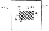
- FIG. 1is a view of a sample RFID tag 110 that may be used with the invention.
- Tag 110is formed on a substrate 115 , which does not conduct.
- Tag 110has an antenna system that includes a rectangular conductive plate 130 .
- Preferably italso includes a complementary matching plate (not shown) on the opposite of substrate 115 .
- Backscatter signalsmay be generated by a circuit that resides on a chip (not shown in FIG. 1 ), and connected to the antenna system. The circuit receives an interrogating RF signal through the antenna during a receive phase, and drives the antenna system accordingly, during a transmit phase.
- Conductive plate 130has two main directions, one along horizontal axis 132 and one along vertical axis 134 . The two directions result in two resonant modes for plate 130 .
- the geometry of plate 130is especially useful if the interrogating RF wave is circularly polarized.
- the circuitsenses an interrogating RF signal, preferably at points on antenna plate 130 that are optimal for the prevailing resonant modes. Such points may, for example, be at antenna point A 1 on axis 132 for a first polarization, and at antenna point A 2 on axis 134 for a second polarization.
- receiving and sendingmay be with respect to a reference, which in turn may be applied to a complementary point of the complementary matching plate.
- wires(not shown) couple the circuit with antenna points A 1 , A 2 , and also with their complementary points on the complementary matching plate.
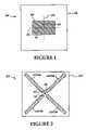
- FIG. 2is a view of another sample RFID tag 210 that may be used with the invention.
- Tag 210is formed on a non-conducting substrate 215 .
- a chip 250 on tag 210includes a circuit, which generates backscatter.
- Two substantially collinear antenna segments ANT 14 , ANT 15form a linear antenna for a first dominant polarization direction, while another two substantially collinear antenna segments ANT 24 , ANT 25 form a second linear antenna for a second dominant polarization direction.
- the geometry of these antennasis especially useful if the interrogating RF wave is linearly polarized. Such a wave will generally generate a component in each of the linear antennas. In some instances, the components will be approximately equal in strength. In other instances, one of the components will be stronger than the other.
- the inventionworks regardless of the orientation of the antennas, or the polarization of the signals. The above was described to illustrate how the description below would be applicable even if the received signals had diverse polarizations. And the operation would be similar if there were no polarization difference.
- FIG. 3shows a circuit 350 according to an embodiment of the invention, which is adapted for using in an RFID tag 310 .
- Tag 310includes an antenna system that may be made in a number of ways, such as shown in FIG. 1 , FIG. 2 , and so on.
- Circuit 350is advantageously implemented as an integrated circuit, although that is not necessary for practicing the invention.
- Circuit 350includes two main RF ports P 1 , P 2 that are suitable for coupling to respective antenna points A 1 , A 2 of the antenna system of the host RFID tag 310 . Coupling may be by wire, bump soldering, or other ways known in the art. Other components may further be coupled between one of ports P 1 , P 2 and its respective one of antenna points A 1 , A 2 , such as an inductor or capacitor for tuning a frequency of the antenna system. Accordingly, port P 1 is adapted to receive a first RF signal RS 1 , and port P 2 is adapted to receive a second RF signal RS 2 , both as a result of the interrogating RF wave.
- the relative magnitudes of signals RS 1 and RS 2may be different at any time, especially if they are derived from antennas of a different polarization, as described above with reference to FIG. 1 , FIG. 2 .
- main RF ports P 1 , P 2While only two main RF ports P 1 , P 2 are shown, the invention is capable of being implemented with three or more just as well. That could be desirable, for example, when more elaborate antenna systems are used to address more polarizations. For each main port being added, a new received signal would become available, and components would have to be added to address it, so that the invention works as described.
- Circuit 350also includes a signal combiner 360 .
- Signal combiner 360receives signals RS 1 , RS 2 and generates a combined signal CSA from them. Combining takes place after some processing of the individual received signals RS 1 , RS 2 . The extent of processing depends on the embodiment.
- processingincludes envelope detection.
- Signal combiner 360includes a first envelope detector ED 1 361 that generates a first processed signal PS 1 from first received signal RS 1 .
- Signal combiner 360moreover includes a second envelope detector ED 2 362 that generates a second processed signal PS 2 from second received signal RS 2 .
- envelope detectors ED 1 361 , ED 2 362may be made as described in more detail later in this document.
- Signal combiner 360further includes an adder 365 to generate the combined signal CSA from first and second processed signals PS 1 , PS 2 .
- adder 365is adapted to add together the first and second processed signals PS 1 , PS 2 .
- the addermay be analog, digital, and so on.
- Circuit 350further includes an analog to digital converter 380 .
- Converter 380is adapted to generate a digital signal CSD from the combined signal CSA.
- Converter 380may be implemented in any way known in the art for processing the output of an envelope detection block in the demodulator circuit of an RFID chip, which receives a signal from a single antenna.
- Circuit 350further includes additional circuitry 390 , which may be adapted to process digital signal CSD as if it were a demodulated signal that was received from a single antenna. Circuitry 390 may access a memory, include a modulator, and even use the same main ports P 1 , P 2 to backscatter.
- the present inventioneventually produces a single demodulated signal, while receiving the combined benefit of both antennas.
- the detectionresults in one of received signals RS 1 , RS 2 dominating the other, that might not make much difference.
- the two received signals RS 1 , RS 2have comparable strength, the combined signal may be stronger than either one of them alone. This is an improvement over the prior art, and even accomplished with fewer components than the prior art.
- FIG. 4is a schematic showing a more particular implementation of signal combiner 360 of FIG. 3 .
- Envelope detectors ED 1 361 , ED 2 362are implemented by AC diodes 461 , 462 , respectively. AC diodes are described in more detail later in this document, with reference to FIG. 6 .
- adder 365includes a node 465 , on which signals PS 1 , PS 2 are added.
- the signals being added at node 465may be electrical currents.
- there is a capacitor 467 coupled to node 465in which case combined signal CSA becomes a voltage.
- Component 468may be any one of a resistor, a current source, a transistor, and so on, as will be evident to a person skilled in the art.
- FIG. 5is a schematic showing a possible implementation of analog to digital converter 380 of FIG. 3 , designed to work especially well for pulse width encoded data.
- Converter 380includes a comparator 560 that outputs digital signal CSD from analog combined signal CSA.
- Converter 380includes optional amplifier 520 , to provide an amplified version of combined signal CSA.
- Converter 380also includes a peak detector 540 to detect peaks of combined signal CSA.
- An offsetting circuit(not shown in FIG. 5 ) may also be employed.
- Comparator 560compares a version of the detected peaks with a version of combined signal CSA, such as combined signal CSA itself, or the amplified version from amplifier 520 , if the latter is provided.
- either one of the versionsmay employ an offset for the signal, either as a subtraction from the peak detector, or as an addition to combined signal CSA.
- the offsetmay be incorporated in the input stage of comparator 560 , by using a deliberately mismatched input differential pair, in which case a separate offsetting circuit is not needed.
- the circuit of FIG. 5may be modified if the data of the interrogating RF wave is encoded differently.
- the DC averageis guaranteed to be 50%.
- an average value detectormay be used instead of employing peak detector 540 .
- the extracted average valuemay be compared in comparator 560 with a version of combined signal CSA.
- FIG. 6is a detailed schematic of a circuit 600 for implementing either one, or each one, of AC diodes 461 , 462 of FIG. 4 .
- An AC diodeis a circuit that operates as a diode blocking the DC component, but passes the AC component of received signals RS 1 , RS 2 .
- Circuit 600includes a transistor 610 , which is biased near its ON/OFF threshold. Another transistor 620 provides a current mirror, to ensure transistor 610 remains biased near its ON/OFF threshold. Bias current is supplied to transistors 610 , 620 through node 645 via a source (not shown).
- a capacitor 630blocks the DC component of signal RS 1 , while permitting substantially all the AC component of signal RS 1 to be passed.
- Capacitors 635 , 637provide signal to the gate of transistor 610 , to switch it ON/OFF from signal RS 1 , for permitting the AC component of signal RS 1 to be passed through transistor 610 .
- Transistor 640acts as a current source for draining current supplied to circuit 600 at node 645 , and as a diode in a remainder of the cycle. Additional components may be further added to circuit 600 , such as a diode to clamp the voltage, to account for the fact that received signal RS 1 may range widely from ⁇ 12 dBm to +20 dBm.
- FIG. 7is flowchart 700 illustrating a method according to an embodiment of the invention.
- the method of flowchart 700may be practiced by different embodiments of the invention, including but not limited to circuit 350 .
- a first RF signalis received.
- a first processed signalis generated from the first received signal.
- the first processed signalis generated by detecting an envelope of the first received signal.
- a second RF signalis received.
- the second received signalmay have a different polarization than the first received signal.
- a second processed signalis generated from the second received signal.
- a combined signalis received from the first and second signals, after some processing.
- the amount of processingvaries with the particular embodiment. Combining may be performed by adding together the first processed signal and the second processed signal. Adding together may be performed at a suitable adder. If currents are being added, then addition may take place at a node.
- a digital signalis generated from the combined signal.
- the digital signalmay be generated by detecting peaks from the combined signal, and comparing a version of the combined signal to a version of the detected peaks. The comparison may employ an offset. Alternately, the digital signal may be generated by detecting an average value of the combined signal, and comparing a version of the combined signal to a version of the detected average value.
- the inventionincludes combinations and subcombinations of the various elements, features, functions and/or properties disclosed herein.
- the following claimsdefine certain combinations and subcombinations, which are regarded as novel and non-obvious. Additional claims for other combinations and subcombinations of features, functions, elements and/or properties may be presented in this or a related document.
Landscapes
- Engineering & Computer Science (AREA)
- Computer Hardware Design (AREA)
- Microelectronics & Electronic Packaging (AREA)
- Physics & Mathematics (AREA)
- General Physics & Mathematics (AREA)
- Theoretical Computer Science (AREA)
- Computer Networks & Wireless Communication (AREA)
- Near-Field Transmission Systems (AREA)
Abstract
Description
This application is a continuation of and commonly assigned U.S. patent application Ser. No. 11/213,632 filed on Aug. 26, 2005, now U.S. Pat. No. 7,423,539, in the name of John D. Hyde, Omer Onen and Ronald A. Oliver, and entitled “RFID Tags Combining Signals Received From Multiple RF Ports”, which is a continuation of U.S. patent application Ser. No. 10/815,474 filed on Mar. 31, 2004, now abandoned.
The present invention is related to the field of Radio Frequency Identification (RFID), and more specifically to devices, circuits, and methods for using multiple RF ports in RFID reader-to-tag communications.
Radio Frequency IDentification (RFID) tags can be used in many ways for locating and identifying objects to which they are attached. RFID tags are particularly useful in product-related and service-related industries for tracking large numbers of objects are being processed, inventoried, or handled. In such cases, an RFID tag is usually attached to individual items, or to their respective packages.
In principle, RFID techniques entail using a device called an RFID reader to interrogate one or more RFID tags. Interrogation is performed by the reader transmitting an interrogating Radio Frequency (RF) wave during a transmit phase. During a receive phase, a tag that has received the interrogating RF wave responds by transmitting back another RF wave, a process known as backscatter. The response may further encode a number stored internally in the tag. The response, and the number if available, is decoded by the reader, which thereby identifies, counts, or otherwise interacts with the associated item. The number can denote a serial number, a price, a date, a destination, other attribute(s), any combination of attributes, and so on.
An RFID tag includes an antenna system, a radio section, a logical section, and a memory. Advances in semiconductor technology have miniaturized the electronics so much that an RFID tag can generate the backscatter while powered by only the RF signal it receives, enabling some RFID tags to operate without a battery.
It is desirable that the antenna system have components such that it can sense many possible types of interrogating RF waves, and from many possible directions, regardless of the orientation of the tag. For example, some RFID tags are provided with antennas that are suitable for sensing RF waves of different polarization. It has been known to have a system of two antennas, receiving two RF signals from them, processing them, and then choosing the strongest one. Such is taught, for example in Patent Application US 2002/0167405A1, published on Nov. 14, 2002 to Shanks et al. An inefficiency, however, is where the two RF signals are processed independently, using one set of components for each of the two RF signals. This requires more circuitry and more power than single antenna systems.
The invention improves over the prior art.
Briefly, the present invention provides circuits, devices and methods for use in RFID tags. A circuit according to the invention has multiple main RF ports, which may be coupled to corresponding points in the antenna system of a host RFID tag. A signal is received in at least some of the RF ports from the interrogating RF wave. At least two of the received signals are combined after some processing, to produce a single combined signal. Additional components process the single combined signal by itself, to decode data transmitted from the reader via the interrogating RF wave.
The invention offers the advantage that more than one antenna can be used, without needing a full sets of components to process the signal received at each main RF port. This results in diminished expenditure of occupied space and electrical power in the device.
A further, unexpected advantage of the invention is that there may be a stronger signal to work with. Indeed, combining the received signals may generate a stronger combined signal than if the stronger one of the received signals is selected individually. The combined signal can be stronger especially if the main RF ports receive signals of equal strength, which results in improved signal to noise ratio and in some instances incrementally larger detection range.
These and other features and advantages of the invention will be better understood from the specification of the invention, which includes the following Detailed Description and accompanying Drawings.
The following Detailed Description proceeds with reference to the accompanying Drawings, in which:
The present invention is now described. While it is disclosed in its preferred form, the specific embodiments of the invention as disclosed herein and illustrated in the drawings are not to be considered in a limiting sense. Rather, these embodiments are provided so that this disclosure will be thorough and complete, and will fully convey the scope of the invention to those skilled in the art. Indeed, it should be readily apparent in view of the present description that the invention may be modified in numerous ways. Among other things, the present invention may be embodied as devices, circuits, methods, and so on. The following detailed description is, therefore, not to be taken in a limiting sense.
As has been mentioned, the invention provides circuits, devices and methods for use in RFID tags. A circuit according to the invention has multiple main RF ports, and the signals they receive are combined into a single combined signal, which is further treated by itself. The invention is now described in more detail.
The invention may be used with RFID tags having many types of antenna systems. Two such systems are described below as a way of example, but not of limitation.
Two substantially collinear antenna segments ANT14, ANT15 form a linear antenna for a first dominant polarization direction, while another two substantially collinear antenna segments ANT24, ANT25 form a second linear antenna for a second dominant polarization direction. The geometry of these antennas is especially useful if the interrogating RF wave is linearly polarized. Such a wave will generally generate a component in each of the linear antennas. In some instances, the components will be approximately equal in strength. In other instances, one of the components will be stronger than the other.
Receiving for a first polarization may be by comparing a signal received on antenna segment ANT14, at an antenna point A1. Comparing would be with respect to a reference, which may be complementary antenna segment ANT15. And receiving for a second polarization may be by comparing a signal received on antenna segment ANT24 at an antenna point A2 with respect to a reference, which may be complementary antenna segment ANT25.
The invention works regardless of the orientation of the antennas, or the polarization of the signals. The above was described to illustrate how the description below would be applicable even if the received signals had diverse polarizations. And the operation would be similar if there were no polarization difference.
While only two main RF ports P1, P2 are shown, the invention is capable of being implemented with three or more just as well. That could be desirable, for example, when more elaborate antenna systems are used to address more polarizations. For each main port being added, a new received signal would become available, and components would have to be added to address it, so that the invention works as described.
In the embodiment ofFIG. 3 , processing includes envelope detection.Signal combiner 360 includes a firstenvelope detector ED1 361 that generates a first processed signal PS1 from first received signal RS1.Signal combiner 360 moreover includes a secondenvelope detector ED2 362 that generates a second processed signal PS2 from second received signal RS2. Each ofenvelope detectors ED1 361,ED2 362 may be made as described in more detail later in this document.
It will be appreciated that the present invention eventually produces a single demodulated signal, while receiving the combined benefit of both antennas. In the event that the detection results in one of received signals RS1, RS2 dominating the other, that might not make much difference. But when the two received signals RS1, RS2 have comparable strength, the combined signal may be stronger than either one of them alone. This is an improvement over the prior art, and even accomplished with fewer components than the prior art.
In the embodiment ofFIG. 4 ,adder 365 includes anode 465, on which signals PS1, PS2 are added. The signals being added atnode 465 may be electrical currents. In one embodiment of the invention, there is acapacitor 467 coupled tonode 465, in which case combined signal CSA becomes a voltage. In some of these embodiments, there is also provided a dischargingcomponent 468 for occasionally discharging thecapacitor 467.Component 468 may be any one of a resistor, a current source, a transistor, and so on, as will be evident to a person skilled in the art.
As will be evident to a person skilled in the art, the circuit ofFIG. 5 may be modified if the data of the interrogating RF wave is encoded differently. For example, for Manchester encoded data, the DC average is guaranteed to be 50%. Accordingly, instead of employingpeak detector 540, an average value detector may be used instead. The extracted average value may be compared incomparator 560 with a version of combined signal CSA.
Circuit600 includes atransistor 610, which is biased near its ON/OFF threshold. Anothertransistor 620 provides a current mirror, to ensuretransistor 610 remains biased near its ON/OFF threshold. Bias current is supplied totransistors node 645 via a source (not shown).
Acapacitor 630 blocks the DC component of signal RS1, while permitting substantially all the AC component of signal RS1 to be passed.Capacitors transistor 610, to switch it ON/OFF from signal RS1, for permitting the AC component of signal RS1 to be passed throughtransistor 610.
Atblock 710, a first RF signal is received. At optionalnext block 720, a first processed signal is generated from the first received signal. In one embodiment, the first processed signal is generated by detecting an envelope of the first received signal.
At anotherblock 730, a second RF signal is received. The second received signal may have a different polarization than the first received signal. At optionalnext block 740, a second processed signal is generated from the second received signal.
Atnext block 750, a combined signal is received from the first and second signals, after some processing. The amount of processing varies with the particular embodiment. Combining may be performed by adding together the first processed signal and the second processed signal. Adding together may be performed at a suitable adder. If currents are being added, then addition may take place at a node.
Atnext block 760, a digital signal is generated from the combined signal. The digital signal may be generated by detecting peaks from the combined signal, and comparing a version of the combined signal to a version of the detected peaks. The comparison may employ an offset. Alternately, the digital signal may be generated by detecting an average value of the combined signal, and comparing a version of the combined signal to a version of the detected average value.
Numerous details have been set forth in this description, which is to be taken as a whole, to provide a more thorough understanding of the invention. In other instances, well-known features have not been described in detail, so as to not obscure unnecessarily the invention.
The invention includes combinations and subcombinations of the various elements, features, functions and/or properties disclosed herein. The following claims define certain combinations and subcombinations, which are regarded as novel and non-obvious. Additional claims for other combinations and subcombinations of features, functions, elements and/or properties may be presented in this or a related document.
Claims (20)
1. A device for use in an RFID tag comprising:
means for generating a combined signal from a first signal received at a first RF port (first received signal) and a second signal received at a second RF port (second received signal);
means for generating a digital signal from the combined signal, the means for generating the digital signal including means for detecting peaks from the combined signal and means for comparing a version of the combined signal to a version of the detected peaks; and
means for generating a first processed signal from the first received signal,
wherein the first processed signal is used to generate the combined signal.
2. The device ofclaim 1 , wherein
the means for generating the first processed signal includes an envelope detector.
3. A device for use in an RFID tag comprising:
means for generating a combined signal from a first signal received at a first RF port (first received signal) and a second signal received at a second RF port (second received signal);
means for generating a digital signal from the combined signal, the means for generating the digital signal including means for detecting an average value of the combined signal and means for comparing a version of the combined signal to a version of the detected average value; and
means for generating a first processed signal from the first received signal,
wherein the first processed signal is used to generate the combined signal.
4. The device ofclaim 3 , wherein
the means for generating the first processed signal includes an envelope detector.
5. A device for use in an RFID tag comprising:
means for receiving a first signal at a first RF port (first received signal);
means for receiving a second signal at a second RF port (second received signal);
means for generating a first processed signal from the first received signal, the means for generating a first processed signal including a first envelope detector;
means for generating a second processed signal from the second received signal, the means for generating the second processed signal including a second envelope detector;
means for generating a combined signal from the first processed signal and the second processed signal; and
means for generating a digital signal from the combined signal.
6. The device ofclaim 5 , wherein
the means for generating the combined signal includes an adder.
7. A method for using a circuit of an RFID tag, comprising:
receiving a first signal at a first RF port (first received signal);
receiving a second signal at a second RF port (second received signal);
generating a combined signal from the first received signal and the second received signal;
generating a digital signal from the combined signal, the digital signal being generated by detecting peaks from the combined signal and comparing a version of the combined signal to a version of the detected peaks; and
generating a first processed signal from the first received signal, wherein the generating the combined signal includes
using the first processed signal to generate the combined signal.
8. The method ofclaim 7 , wherein
the generating the first processed signal is performed by detecting an envelope of the first received signal.
9. The method ofclaim 6 , further comprising:
generating a second processed signal from the second received signal; and wherein the generating the combined signal includes using the second processed signal to generate the combined signal.
10. The method ofclaim 9 , wherein
the generating the combined signal includes adding the first processed signal and the second processed signal.
11. The method ofclaim 10 , wherein
the generating the combined signal is performed at a node.
12. The method ofclaim 11 , further comprising:
storing charge at the node.
13. The method ofclaim 12 , further comprising:
discharging charge from the charge stored at the node.
14. A method for using a circuit of an RFID tag, comprising:
receiving a first signal at a first RF port (first received signal);
receiving a second signal at a second RF port (second received signal);
generating a combined signal from the first received signal and the second received signal;
generating a digital signal from the combined signal, the digital signal being generated by detecting an average value of the combined signal and comparing a version of the combined signal to a version of the detected average value; and
generating a first processed signal from the first received signal, wherein the generating the combined signal includes
using the first processed signal to generate the combined signal.
15. The method ofclaim 14 , wherein
the generating the first processed signal is performed by detecting an envelope of the first received signal.
16. The method ofclaim 15 , further comprising:
generating a second processed signal from the second received signal; and wherein the generating the combined signal includes using the second processed signal to generate the combined signal.
17. The method ofclaim 16 , wherein
the generating the combined signal includes adding the first processed signal and the second processed signal.
18. The method ofclaim 17 , wherein
the generating the combined signal is performed at a node.
19. The method ofclaim 18 , further comprising:
storing charge at the node.
20. The method ofclaim 19 , further comprising:
discharging charge from the charge stored at the node.
Priority Applications (1)
| Application Number | Priority Date | Filing Date | Title |
|---|---|---|---|
| US11/803,995US7525438B2 (en) | 2004-03-31 | 2007-05-15 | RFID tags combining signals received from multiple RF ports |
Applications Claiming Priority (3)
| Application Number | Priority Date | Filing Date | Title |
|---|---|---|---|
| US81547404A | 2004-03-31 | 2004-03-31 | |
| US11/213,632US7423539B2 (en) | 2004-03-31 | 2005-08-26 | RFID tags combining signals received from multiple RF ports |
| US11/803,995US7525438B2 (en) | 2004-03-31 | 2007-05-15 | RFID tags combining signals received from multiple RF ports |
Related Parent Applications (1)
| Application Number | Title | Priority Date | Filing Date |
|---|---|---|---|
| US11/213,632ContinuationUS7423539B2 (en) | 2004-03-31 | 2005-08-26 | RFID tags combining signals received from multiple RF ports |
Publications (2)
| Publication Number | Publication Date |
|---|---|
| US20070216533A1 US20070216533A1 (en) | 2007-09-20 |
| US7525438B2true US7525438B2 (en) | 2009-04-28 |
Family
ID=34963879
Family Applications (2)
| Application Number | Title | Priority Date | Filing Date |
|---|---|---|---|
| US11/213,632Expired - LifetimeUS7423539B2 (en) | 2004-03-31 | 2005-08-26 | RFID tags combining signals received from multiple RF ports |
| US11/803,995Expired - LifetimeUS7525438B2 (en) | 2004-03-31 | 2007-05-15 | RFID tags combining signals received from multiple RF ports |
Family Applications Before (1)
| Application Number | Title | Priority Date | Filing Date |
|---|---|---|---|
| US11/213,632Expired - LifetimeUS7423539B2 (en) | 2004-03-31 | 2005-08-26 | RFID tags combining signals received from multiple RF ports |
Country Status (1)
| Country | Link |
|---|---|
| US (2) | US7423539B2 (en) |
Cited By (18)
| Publication number | Priority date | Publication date | Assignee | Title |
|---|---|---|---|---|
| US20110025470A1 (en)* | 2005-05-26 | 2011-02-03 | Robert Tiernay | Automatic mode detection in a dual mode rfid tag |
| WO2013006954A1 (en)* | 2011-07-11 | 2013-01-17 | Securekey Technologies Inc. | Streamlined apparatus and methods for rfid communication |
| US8690057B2 (en) | 2012-03-06 | 2014-04-08 | A-I Packaging Solutions, Inc. | Radio frequency identification system for tracking and managing materials in a manufacturing process |
| US9990518B2 (en) | 2016-11-04 | 2018-06-05 | Intermec, Inc. | Systems and methods for controlling radio-frequency indentification (RFID) tag communication |
| USD854612S1 (en) | 2016-10-28 | 2019-07-23 | Square, Inc. | Electronic device |
| US10430783B2 (en) | 2016-10-03 | 2019-10-01 | Square, Inc. | Transmit phase detection circuit |
| US10430622B2 (en) | 2017-06-29 | 2019-10-01 | Intermec, Inc. | RFID tag with reconfigurable properties and/or reconfiguring capability |
| US10452968B2 (en) | 2017-06-14 | 2019-10-22 | Intermec, Inc. | Method to increase RFID tag sensitivity |
| US11023851B2 (en) | 2018-03-30 | 2021-06-01 | A-1 Packaging Solutions, Inc. | RFID-based inventory tracking system |
| US11348067B2 (en) | 2018-03-30 | 2022-05-31 | A-1 Packaging Solutions, Inc. | RFID-based inventory tracking system |
| US11443158B2 (en) | 2019-04-22 | 2022-09-13 | A-1 Packaging Solutions, Inc. | Easily attachable RFID tag and method of making the same |
| US11755874B2 (en) | 2021-03-03 | 2023-09-12 | Sensormatic Electronics, LLC | Methods and systems for heat applied sensor tag |
| US11769026B2 (en) | 2019-11-27 | 2023-09-26 | Sensormatic Electronics, LLC | Flexible water-resistant sensor tag |
| US11861440B2 (en) | 2019-09-18 | 2024-01-02 | Sensormatic Electronics, LLC | Systems and methods for providing tags adapted to be incorporated with or in items |
| US11869324B2 (en) | 2021-12-23 | 2024-01-09 | Sensormatic Electronics, LLC | Securing a security tag into an article |
| US11928538B2 (en) | 2019-09-18 | 2024-03-12 | Sensormatic Electronics, LLC | Systems and methods for laser tuning and attaching RFID tags to products |
| US12175849B2 (en) | 2018-05-22 | 2024-12-24 | Tyco Fire & Security Gmbh | Elongate flexible tag |
| US12223814B2 (en) | 2019-09-16 | 2025-02-11 | Sensormatic Electronics, LLC | Security tag for textiles using conductive thread |
Families Citing this family (21)
| Publication number | Priority date | Publication date | Assignee | Title |
|---|---|---|---|---|
| CN100468740C (en) | 2004-04-02 | 2009-03-11 | 株式会社半导体能源研究所 | Semiconductor device and driving method thereof |
| US7689195B2 (en)* | 2005-02-22 | 2010-03-30 | Broadcom Corporation | Multi-protocol radio frequency identification transponder tranceiver |
| US7893813B2 (en)* | 2005-07-28 | 2011-02-22 | Intermec Ip Corp. | Automatic data collection device, method and article |
| WO2007035863A2 (en) | 2005-09-21 | 2007-03-29 | Intermec Ip Corp. | Radio frequency identification tags based on coalition formation |
| AU2006338233A1 (en)* | 2006-02-15 | 2007-08-23 | Sensormatic Electronics, LLC | RF switched RFID multiplexer |
| US8120461B2 (en)* | 2006-04-03 | 2012-02-21 | Intermec Ip Corp. | Automatic data collection device, method and article |
| US8002173B2 (en) | 2006-07-11 | 2011-08-23 | Intermec Ip Corp. | Automatic data collection device, method and article |
| US20080136621A1 (en)* | 2006-12-07 | 2008-06-12 | Symbol Technologies, Inc. | Methods and apparatus for wlan management using rf tags |
| US20080180254A1 (en)* | 2007-01-31 | 2008-07-31 | Kajander John A | Circularly-polarized rfid tag antenna structure |
| JP4854604B2 (en)* | 2007-06-20 | 2012-01-18 | ルネサスエレクトロニクス株式会社 | Semiconductor integrated circuit, card equipped with the same, and operation method thereof |
| US9294157B2 (en)* | 2007-08-20 | 2016-03-22 | Gui-Yang Lu | Radio-frequency identification system |
| US20100145455A1 (en) | 2008-12-10 | 2010-06-10 | Innvotec Surgical, Inc. | Lockable spinal implant |
| US8696751B2 (en)* | 2008-12-10 | 2014-04-15 | Coalign Innovations, Inc. | Adjustable distraction cage with linked locking mechanisms |
| US9142881B1 (en) | 2008-08-29 | 2015-09-22 | Impinj, Inc. | RFID tag circuits with floating differential inputs |
| US9087281B2 (en)* | 2009-06-12 | 2015-07-21 | Impinj, Inc. | Dual-frequency RFID tag with isolated inputs |
| FR2953332A1 (en)* | 2010-06-23 | 2011-06-03 | Continental Automotive France | Method for providing communication between remote vehicle and control card, involves integrating two antenna elements to remote control card, where elements emit components that have same frequency and are phase shifted |
| US9331384B2 (en)* | 2012-09-13 | 2016-05-03 | Qualcomm Incorporated | Battery antenna having a secondary radiator |
| US9865105B2 (en)* | 2013-06-21 | 2018-01-09 | X-Card Holdings, Llc | Electronic credential signal activation systems and methods |
| US10503937B2 (en) | 2015-12-31 | 2019-12-10 | Intermec, Inc. | Self-steering RFID tags |
| AU2017228529B2 (en) | 2016-09-12 | 2022-03-10 | Vb Spine Us Opco Llc | Interbody implant with independent control of expansion at multiple locations |
| US9973081B1 (en)* | 2017-08-17 | 2018-05-15 | Qualcomm Incorporated | Low-power low-duty-cycle switched-capacitor voltage divider |
Citations (135)
| Publication number | Priority date | Publication date | Assignee | Title |
|---|---|---|---|---|
| US4315272A (en) | 1979-05-21 | 1982-02-09 | Raytheon Company | Field effect transistor |
| US4479260A (en) | 1981-11-27 | 1984-10-23 | U.S. Philips Corporation | Coupling and mixing circuit comprising a dual source transistor |
| US4584709A (en) | 1983-07-06 | 1986-04-22 | Motorola, Inc. | Homotropic antenna system for portable radio |
| US4611184A (en) | 1984-07-13 | 1986-09-09 | Rca Corporation | Microwave frequency power divider |
| US4730188A (en) | 1984-02-15 | 1988-03-08 | Identification Devices, Inc. | Identification system |
| US4742567A (en) | 1985-02-01 | 1988-05-03 | Toyota Jidosha Kabushiki Kaisha | Automobile antenna system |
| US4783783A (en) | 1985-07-29 | 1988-11-08 | Hitachi, Ltd. | Data processing system having pipeline arithmetic/logic units |
| US4809009A (en) | 1988-01-25 | 1989-02-28 | Grimes Dale M | Resonant antenna |
| US4857893A (en) | 1986-07-18 | 1989-08-15 | Bi Inc. | Single chip transponder device |
| US4864314A (en) | 1985-01-17 | 1989-09-05 | Cossor Electronics Limited | Dual band antennas with microstrip array mounted atop a slot array |
| US4935702A (en) | 1988-12-09 | 1990-06-19 | Synaptics, Inc. | Subthreshold CMOS amplifier with offset adaptation |
| US4953157A (en) | 1989-04-19 | 1990-08-28 | American Telephone And Telegraph Company | Programmable data packet buffer prioritization arrangement |
| US4977616A (en) | 1987-11-30 | 1990-12-11 | Motorola, Inc. | Antenna selection control circuit |
| EP0416264A2 (en)* | 1989-09-06 | 1991-03-13 | Hughes Aircraft Company | Adaptive polarization combining system |
| US5075691A (en) | 1989-07-24 | 1991-12-24 | Motorola, Inc. | Multi-resonant laminar antenna |
| US5142292A (en) | 1991-08-05 | 1992-08-25 | Checkpoint Systems, Inc. | Coplanar multiple loop antenna for electronic article surveillance systems |
| US5175418A (en) | 1989-12-19 | 1992-12-29 | Sony Corporation | Information card system |
| EP0298618B1 (en) | 1987-07-08 | 1993-10-27 | Tektronix Inc. | Interleaved digitizer array with calibrated sample timing |
| US5280286A (en) | 1992-06-12 | 1994-01-18 | Smart Tag Systems, Inc. | Surveillance and identification system antennas |
| US5430441A (en) | 1993-10-12 | 1995-07-04 | Motorola, Inc. | Transponding tag and method |
| US5448110A (en) | 1992-06-17 | 1995-09-05 | Micron Communications, Inc. | Enclosed transceiver |
| US5499397A (en) | 1994-05-02 | 1996-03-12 | Motorola, Inc. | Switched antenna diversity algorithm employing received signal strength, phase errors and recovered clock |
| US5507035A (en) | 1993-04-30 | 1996-04-09 | International Business Machines Corporation | Diversity transmission strategy in mobile/indoor cellula radio communications |
| US5528222A (en) | 1994-09-09 | 1996-06-18 | International Business Machines Corporation | Radio frequency circuit and memory in thin flexible package |
| US5572226A (en) | 1992-05-15 | 1996-11-05 | Micron Technology, Inc. | Spherical antenna pattern(s) from antenna(s) arranged in a two-dimensional plane for use in RFID tags and labels |
| US5771021A (en) | 1993-10-04 | 1998-06-23 | Amtech Corporation | Transponder employing modulated backscatter microstrip double patch antenna |
| US5805632A (en) | 1992-11-19 | 1998-09-08 | Cirrus Logic, Inc. | Bit rate doubler for serial data transmission or storage |
| US5825329A (en) | 1993-10-04 | 1998-10-20 | Amtech Corporation | Modulated backscatter microstrip patch antenna |
| US5842118A (en) | 1996-12-18 | 1998-11-24 | Micron Communications, Inc. | Communication system including diversity antenna queuing |
| US5923300A (en) | 1997-04-03 | 1999-07-13 | Destron-Fearing Corporation | Multi-phase transmitter with single receive antenna for transponder interrogator |
| US5929760A (en) | 1997-10-20 | 1999-07-27 | Escort Memory Systems | RFID conveyor antenna |
| US5933039A (en) | 1992-12-07 | 1999-08-03 | Dallas Semiconductor Corporation | Programmable delay line |
| US5939945A (en) | 1996-07-25 | 1999-08-17 | Siemens Aktiengesellschaft | Amplifier with neuron MOS transistors |
| US5952922A (en) | 1996-12-31 | 1999-09-14 | Lucent Technologies Inc. | In-building modulated backscatter system |
| US5995048A (en) | 1996-05-31 | 1999-11-30 | Lucent Technologies Inc. | Quarter wave patch antenna |
| US6005529A (en) | 1996-12-04 | 1999-12-21 | Ico Services Ltd. | Antenna assembly with relocatable antenna for mobile transceiver |
| US6025784A (en) | 1998-02-12 | 2000-02-15 | Micron Technology, Inc. | Vehicles, license plate frame assemblies, methods of forming license plate frames, and methods of attaching RFIDs, transponders and modulators to vehicles |
| US6043746A (en) | 1999-02-17 | 2000-03-28 | Microchip Technology Incorporated | Radio frequency identification (RFID) security tag for merchandise and method therefor |
| US6045652A (en) | 1992-06-17 | 2000-04-04 | Micron Communications, Inc. | Method of manufacturing an enclosed transceiver |
| US6057803A (en) | 1996-03-19 | 2000-05-02 | Matsushita Electric Industrial, Co., Ltd. | Antenna apparatus |
| US6060815A (en) | 1997-08-18 | 2000-05-09 | X-Cyte, Inc. | Frequency mixing passive transponder |
| US6069564A (en) | 1998-09-08 | 2000-05-30 | Hatano; Richard | Multi-directional RFID antenna |
| US6078259A (en) | 1994-09-09 | 2000-06-20 | Intermec Ip Corp. | Radio frequency identification tag |
| US6097345A (en) | 1998-11-03 | 2000-08-01 | The Ohio State University | Dual band antenna for vehicles |
| US6118379A (en) | 1997-12-31 | 2000-09-12 | Intermec Ip Corp. | Radio frequency identification transponder having a spiral antenna |
| US6130632A (en) | 1998-04-16 | 2000-10-10 | National Semiconductor Corporation | Digitally self-calibrating current-mode D/A converter |
| US6130612A (en) | 1997-01-05 | 2000-10-10 | Intermec Ip Corp. | Antenna for RF tag with a magnetoelastic resonant core |
| US6130570A (en) | 1997-09-18 | 2000-10-10 | Samsung Electronics Co., Ltd. | MESFET circuit utilizing only positive power supplies |
| US6134182A (en) | 1999-10-19 | 2000-10-17 | International Business Machines Corporation | Cycle independent data to echo clock tracking circuit |
| US6147655A (en) | 1998-11-05 | 2000-11-14 | Single Chip Systems Corporation | Flat loop antenna in a single plane for use in radio frequency identification tags |
| US6147605A (en) | 1998-09-11 | 2000-11-14 | Motorola, Inc. | Method and apparatus for an optimized circuit for an electrostatic radio frequency identification tag |
| US6166706A (en) | 1998-11-04 | 2000-12-26 | Checkpoint Systems, Inc. | Rotating field antenna with a magnetically coupled quadrature loop |
| US6184841B1 (en) | 1996-12-31 | 2001-02-06 | Lucent Technologies Inc. | Antenna array in an RFID system |
| US6215402B1 (en) | 1998-03-13 | 2001-04-10 | Intermec Ip Corp. | Radio frequency identification transponder employing patch antenna |
| US6249260B1 (en) | 1999-07-16 | 2001-06-19 | Comant Industries, Inc. | T-top antenna for omni-directional horizontally-polarized operation |
| US6266362B1 (en) | 1993-03-17 | 2001-07-24 | Micron Technology, Inc. | Modulated spread spectrum in RF identification systems method |
| US6268796B1 (en) | 1997-12-12 | 2001-07-31 | Alfred Gnadinger | Radio frequency identification transponder having integrated antenna |
| US6271793B1 (en) | 1999-11-05 | 2001-08-07 | International Business Machines Corporation | Radio frequency (RF) transponder (Tag) with composite antenna |
| US6281794B1 (en) | 1998-01-02 | 2001-08-28 | Intermec Ip Corp. | Radio frequency transponder with improved read distance |
| WO2001073854A2 (en) | 2000-03-25 | 2001-10-04 | Peregrine Semiconductor Corporation | Variable capacitor with programmability |
| US6320788B1 (en) | 1998-09-25 | 2001-11-20 | Sandisk Corporation | Programmable impedance device |
| US20010043162A1 (en) | 1999-01-13 | 2001-11-22 | Babb Susan M. | Laminate RFID label and method of manufacture |
| US6340932B1 (en) | 1998-06-02 | 2002-01-22 | Rf Code, Inc. | Carrier with antenna for radio frequency identification |
| US6346922B1 (en) | 1999-02-01 | 2002-02-12 | Supersensor (Proprietary) Limited | Hybrid antenna arrangement for use with electronic identification systems |
| US6357025B1 (en) | 1992-11-20 | 2002-03-12 | Micron Technology, Inc. | Testing and burn-in of IC chips using radio frequency transmission |
| US6366260B1 (en) | 1998-11-02 | 2002-04-02 | Intermec Ip Corp. | RFID tag employing hollowed monopole antenna |
| US6366629B1 (en) | 1998-11-03 | 2002-04-02 | Tektronix, Inc. | Method of estimating timing phase and rate offsets in digital data |
| US6396438B1 (en) | 1999-09-24 | 2002-05-28 | Slc Technologies | System and method for locating radio frequency identification tags using three-phase antenna |
| US20020067315A1 (en) | 1999-08-16 | 2002-06-06 | Waldemar Kunysz | Aperture coupled slot array antenna |
| US20020075184A1 (en) | 1997-08-20 | 2002-06-20 | Tuttle Mark E. | Communication devices, remote intelligent communication devices, electronic communication devices, methods of forming remote intelligent communication devices and methods of forming a radio frequency identification device |
| US20020109636A1 (en) | 2001-01-16 | 2002-08-15 | Johnson Daniel L. | Omnidirectional RFID antenna |
| US6445297B1 (en) | 2000-10-10 | 2002-09-03 | Escort Memory Systems | Modular RFID antenna system |
| US20020126057A1 (en) | 2000-07-18 | 2002-09-12 | King Patrick F. | Wireless communication device and method |
| US20020167405A1 (en) | 2001-02-12 | 2002-11-14 | Matrics, Inc. | Radio frequency identification architecture |
| US20020175805A9 (en) | 2000-11-29 | 2002-11-28 | Ludwig Kipp | Method and system for communicating with and tracking RFID transponders |
| US6501807B1 (en) | 1998-02-06 | 2002-12-31 | Intermec Ip Corp. | Data recovery system for radio frequency identification interrogator |
| US6517000B1 (en) | 1999-05-03 | 2003-02-11 | Psc Scanning, Inc. | Dual ended cable for connecting electronic article surveillance antenna with RFID equipment |
| US20030090313A1 (en) | 2001-10-10 | 2003-05-15 | Burgener Mark L. | Switch circuit and method of switching radio frequency signals |
| US6571617B2 (en) | 2001-01-17 | 2003-06-03 | Microchip Technology Incorporated | Method and apparatus using directional antenna or learning modes for tire inflation pressure monitoring and location determination |
| US6603801B1 (en) | 1998-01-16 | 2003-08-05 | Intersil Americas Inc. | Spread spectrum transceiver for use in wireless local area network and having multipath mitigation |
| US20030184495A1 (en) | 2002-04-01 | 2003-10-02 | Isao Tomon | Non-contact information communication apparatus |
| US20040001024A1 (en) | 2002-06-27 | 2004-01-01 | Killen William D. | High efficiency printed circuit array of log-periodic dipole arrays |
| US6677917B2 (en) | 2002-02-25 | 2004-01-13 | Koninklijke Philips Electronics N.V. | Fabric antenna for tags |
| US6700491B2 (en) | 2002-06-14 | 2004-03-02 | Sensormatic Electronics Corporation | Radio frequency identification tag with thin-film battery for antenna |
| US6701605B2 (en) | 2001-10-09 | 2004-03-09 | Sonoco Development, Inc. | Conductive electrical element and antenna with ink additive technology |
| US6717923B1 (en) | 1998-02-04 | 2004-04-06 | Micron Technology, Inc. | Communication devices, a radio frequency identification device, and methods of communicating |
| US20040075616A1 (en) | 2000-12-18 | 2004-04-22 | Takanori Endo | Antenna for rfid |
| US20040113746A1 (en) | 2002-12-17 | 2004-06-17 | M/A-Com, Inc. | Series/shunt switch and method of control |
| US20040125023A1 (en) | 2002-12-26 | 2004-07-01 | Tetsuya Fujii | Wave-transmitting cover, and method for producing it |
| USD492670S1 (en) | 2003-06-13 | 2004-07-06 | Hon Hai Precision Ind. Co., Ltd | Planar antenna |
| US20040137844A1 (en) | 2002-09-02 | 2004-07-15 | Em Microelectronic - Marin Sa | Adjustment of the detection, transmission and/or reception parameters of an RFID reader as a function of ambient electromagnetic noise |
| USD493446S1 (en) | 2003-05-20 | 2004-07-27 | Hon Hai Precision Ind. Co., Ltd. | Antenna |
| WO2004063982A1 (en) | 2003-01-03 | 2004-07-29 | Battelle Memorial Institute | Tags, wireless communication systems and wireless communications methods |
| US20040178265A1 (en) | 2000-07-21 | 2004-09-16 | Ngoc-Chau Bui | High sensitivity reader for passive transponders |
| US20040183743A1 (en) | 2003-03-17 | 2004-09-23 | Reasoner Kelly J. | Enhanced antenna using flexible circuitry |
| US6830193B2 (en) | 2001-11-29 | 2004-12-14 | Matsushita Electric Industrial Co., Ltd. | Non-contact IC card |
| US20050028032A1 (en) | 2003-05-28 | 2005-02-03 | John Klein | Backup cell controller |
| US20050024186A1 (en) | 2003-08-01 | 2005-02-03 | Atmel Germany Gmbh | Method for selecting one or more transponders |
| US6885344B2 (en) | 2002-11-19 | 2005-04-26 | Farrokh Mohamadi | High-frequency antenna array |
| US20050104793A1 (en) | 2003-11-18 | 2005-05-19 | Alps Electric Co., Ltd. | Circular polarization slot antenna apparatus capable of being easily miniaturized |
| US20050104789A1 (en) | 2003-07-29 | 2005-05-19 | Hitachi Kokusai Electric Inc. | Antenna device commonly used for two frequencies |
| US20050104797A1 (en) | 2003-11-17 | 2005-05-19 | Mccollum Gail E. | Low profile television antenna |
| US20050134460A1 (en) | 2003-12-04 | 2005-06-23 | Mitsuo Usami | Antenna for radio frequency identification |
| US20050170784A1 (en) | 2004-01-27 | 2005-08-04 | Omron Corporation | Read-write processing apparatus and method for RFID tag |
| US20050212674A1 (en) | 2004-03-29 | 2005-09-29 | Impinj, Inc., A Delaware Corporation | RFID tag uncoupling one of its antenna ports and methods |
| US20050225435A1 (en) | 2004-04-13 | 2005-10-13 | Impinj, Inc. | Adaptable bandwidth RFID tags |
| US20050227631A1 (en) | 2004-04-13 | 2005-10-13 | Robinett Robert L | Multi-antenna transceiver system |
| US20050231434A1 (en) | 2002-05-01 | 2005-10-20 | The Regents Of The University Of Michigan | Slot antenna |
| US20050253688A1 (en) | 2004-05-11 | 2005-11-17 | Sony Corporation | Radio communication system, radio communication device, and radio communication method |
| US20050259030A1 (en) | 2004-05-24 | 2005-11-24 | Mitsubishi Denki Kabushiki Kaisha | Circularly polarized antenna and rectenna using this antenna |
| US20050270185A1 (en) | 2004-06-04 | 2005-12-08 | Impinj, Inc. | Decoding with memory in RFID system |
| US20050270189A1 (en) | 2004-05-24 | 2005-12-08 | Impinj, Inc. | RFID readers and RFID tags communicating using extensible bit vectors |
| US20050269408A1 (en) | 2004-06-04 | 2005-12-08 | Impinj, Inc. | RFID joint acquisition of time sync and timebase |
| US20060001579A1 (en) | 2004-06-30 | 2006-01-05 | Mitsumi Electric Co. Ltd. | Antenna device having excellent horizontal and vertical polarization characteristics |
| US20060028379A1 (en) | 2000-03-13 | 2006-02-09 | Rcd Technology Corp. | Method for forming radio frequency antenna |
| US20060038724A1 (en) | 2004-08-21 | 2006-02-23 | Samsung Electronics Co., Ltd. | Small planar antenna with enhanced bandwidth and small rectenna for RFID and wireless sensor transponder |
| US20060038730A1 (en) | 2004-08-19 | 2006-02-23 | Harris Corporation | Litzendraht loop antenna and associated methods |
| US20060038725A1 (en) | 2004-08-21 | 2006-02-23 | Samsung Electronics Co., Ltd. | Small planar antenna with enhanced bandwidth and small strip radiator |
| US7005968B1 (en) | 2000-06-07 | 2006-02-28 | Symbol Technologies, Inc. | Wireless locating and tracking systems |
| US20060044192A1 (en) | 2003-12-23 | 2006-03-02 | 3M Innovative Properties Company | Ultra high frequency radio frequency identification tag |
| US20060055620A1 (en) | 2004-03-29 | 2006-03-16 | Impinj, Inc. | Circuits for RFID tags with multiple non-independently driven RF ports |
| US20060109128A1 (en) | 2004-11-19 | 2006-05-25 | Bernard Barink | Homodyne RFID receiver and method |
| US20060139223A1 (en) | 2004-12-29 | 2006-06-29 | Agc Automotive Americas R&D Inc. | Slot coupling patch antenna |
| US20060145926A1 (en) | 2004-12-08 | 2006-07-06 | Won-Kyu Choi | Dual polarization antenna and RFID reader employing the same |
| US20060186995A1 (en) | 2005-02-22 | 2006-08-24 | Jiangfeng Wu | Multi-protocol radio frequency identification reader tranceiver |
| US20060208900A1 (en) | 2005-01-19 | 2006-09-21 | X-Ether, Inc. | Rfid antenna |
| US20060208897A1 (en) | 2005-03-04 | 2006-09-21 | Chiu Lihu M | Capacitive RFID tag encoder |
| US20060238301A1 (en) | 2005-02-22 | 2006-10-26 | Jiangfeng Wu | Multi-protocol radio frequency identification transponder tranceiver |
| US20060244676A1 (en) | 2005-04-28 | 2006-11-02 | Kouichi Uesaka | Signal processing circuit, and non-contact IC card and tag with the use thereof |
| US20060262023A1 (en) | 2005-05-09 | 2006-11-23 | The Regents Of The University Of California | Channelized log-periodic antenna with matched coupling |
| US20070024446A1 (en) | 2004-08-10 | 2007-02-01 | Impinj, Inc. | Rfid readers and tags transmitting and receiving waveform segment with ending-triggering transition |
| US7214569B2 (en) | 2002-01-23 | 2007-05-08 | Alien Technology Corporation | Apparatus incorporating small-feature-size and large-feature-size components and method for making same |
| US20070103379A1 (en) | 2005-11-10 | 2007-05-10 | Garby Sandra M | Method for an element using two resist layers |
| US20070152901A1 (en) | 2006-02-10 | 2007-07-05 | Symbol Technologies, Inc. | Antenna designs for radio frequency identification (RFID) tags |
| US20070205953A1 (en) | 2004-06-16 | 2007-09-06 | Axalto Sa | Shielded Contactless Electronic Document |
- 2005
- 2005-08-26USUS11/213,632patent/US7423539B2/ennot_activeExpired - Lifetime
- 2007
- 2007-05-15USUS11/803,995patent/US7525438B2/ennot_activeExpired - Lifetime
Patent Citations (144)
| Publication number | Priority date | Publication date | Assignee | Title |
|---|---|---|---|---|
| US4315272A (en) | 1979-05-21 | 1982-02-09 | Raytheon Company | Field effect transistor |
| US4479260A (en) | 1981-11-27 | 1984-10-23 | U.S. Philips Corporation | Coupling and mixing circuit comprising a dual source transistor |
| US4584709A (en) | 1983-07-06 | 1986-04-22 | Motorola, Inc. | Homotropic antenna system for portable radio |
| US4730188A (en) | 1984-02-15 | 1988-03-08 | Identification Devices, Inc. | Identification system |
| US4611184A (en) | 1984-07-13 | 1986-09-09 | Rca Corporation | Microwave frequency power divider |
| US4864314A (en) | 1985-01-17 | 1989-09-05 | Cossor Electronics Limited | Dual band antennas with microstrip array mounted atop a slot array |
| US4742567A (en) | 1985-02-01 | 1988-05-03 | Toyota Jidosha Kabushiki Kaisha | Automobile antenna system |
| US4783783A (en) | 1985-07-29 | 1988-11-08 | Hitachi, Ltd. | Data processing system having pipeline arithmetic/logic units |
| US4857893A (en) | 1986-07-18 | 1989-08-15 | Bi Inc. | Single chip transponder device |
| EP0298618B1 (en) | 1987-07-08 | 1993-10-27 | Tektronix Inc. | Interleaved digitizer array with calibrated sample timing |
| US4977616A (en) | 1987-11-30 | 1990-12-11 | Motorola, Inc. | Antenna selection control circuit |
| US4809009A (en) | 1988-01-25 | 1989-02-28 | Grimes Dale M | Resonant antenna |
| US4935702A (en) | 1988-12-09 | 1990-06-19 | Synaptics, Inc. | Subthreshold CMOS amplifier with offset adaptation |
| US4953157A (en) | 1989-04-19 | 1990-08-28 | American Telephone And Telegraph Company | Programmable data packet buffer prioritization arrangement |
| US5075691A (en) | 1989-07-24 | 1991-12-24 | Motorola, Inc. | Multi-resonant laminar antenna |
| EP0416264A2 (en)* | 1989-09-06 | 1991-03-13 | Hughes Aircraft Company | Adaptive polarization combining system |
| US5068668A (en)* | 1989-09-06 | 1991-11-26 | Hughes Aircraft Company | Adaptive polarization combining system |
| EP0435137B1 (en) | 1989-12-19 | 1999-07-28 | Sony Corporation | Information card system |
| US5175418A (en) | 1989-12-19 | 1992-12-29 | Sony Corporation | Information card system |
| US5142292A (en) | 1991-08-05 | 1992-08-25 | Checkpoint Systems, Inc. | Coplanar multiple loop antenna for electronic article surveillance systems |
| US5572226A (en) | 1992-05-15 | 1996-11-05 | Micron Technology, Inc. | Spherical antenna pattern(s) from antenna(s) arranged in a two-dimensional plane for use in RFID tags and labels |
| US5719586A (en) | 1992-05-15 | 1998-02-17 | Micron Communications, Inc. | Spherical antenna pattern(s) from antenna(s) arranged in a two-dimensional plane for use in RFID tags and labels |
| US5280286A (en) | 1992-06-12 | 1994-01-18 | Smart Tag Systems, Inc. | Surveillance and identification system antennas |
| US6045652A (en) | 1992-06-17 | 2000-04-04 | Micron Communications, Inc. | Method of manufacturing an enclosed transceiver |
| US6078791A (en) | 1992-06-17 | 2000-06-20 | Micron Communications, Inc. | Radio frequency identification transceiver and antenna |
| US5448110A (en) | 1992-06-17 | 1995-09-05 | Micron Communications, Inc. | Enclosed transceiver |
| US5805632A (en) | 1992-11-19 | 1998-09-08 | Cirrus Logic, Inc. | Bit rate doubler for serial data transmission or storage |
| US6357025B1 (en) | 1992-11-20 | 2002-03-12 | Micron Technology, Inc. | Testing and burn-in of IC chips using radio frequency transmission |
| US5933039A (en) | 1992-12-07 | 1999-08-03 | Dallas Semiconductor Corporation | Programmable delay line |
| US6266362B1 (en) | 1993-03-17 | 2001-07-24 | Micron Technology, Inc. | Modulated spread spectrum in RF identification systems method |
| US5507035A (en) | 1993-04-30 | 1996-04-09 | International Business Machines Corporation | Diversity transmission strategy in mobile/indoor cellula radio communications |
| US5771021A (en) | 1993-10-04 | 1998-06-23 | Amtech Corporation | Transponder employing modulated backscatter microstrip double patch antenna |
| US5825329A (en) | 1993-10-04 | 1998-10-20 | Amtech Corporation | Modulated backscatter microstrip patch antenna |
| US5430441A (en) | 1993-10-12 | 1995-07-04 | Motorola, Inc. | Transponding tag and method |
| US5499397A (en) | 1994-05-02 | 1996-03-12 | Motorola, Inc. | Switched antenna diversity algorithm employing received signal strength, phase errors and recovered clock |
| US5528222A (en) | 1994-09-09 | 1996-06-18 | International Business Machines Corporation | Radio frequency circuit and memory in thin flexible package |
| US6078259A (en) | 1994-09-09 | 2000-06-20 | Intermec Ip Corp. | Radio frequency identification tag |
| US6057803A (en) | 1996-03-19 | 2000-05-02 | Matsushita Electric Industrial, Co., Ltd. | Antenna apparatus |
| US5995048A (en) | 1996-05-31 | 1999-11-30 | Lucent Technologies Inc. | Quarter wave patch antenna |
| US5939945A (en) | 1996-07-25 | 1999-08-17 | Siemens Aktiengesellschaft | Amplifier with neuron MOS transistors |
| US6005529A (en) | 1996-12-04 | 1999-12-21 | Ico Services Ltd. | Antenna assembly with relocatable antenna for mobile transceiver |
| US5842118A (en) | 1996-12-18 | 1998-11-24 | Micron Communications, Inc. | Communication system including diversity antenna queuing |
| US5952922A (en) | 1996-12-31 | 1999-09-14 | Lucent Technologies Inc. | In-building modulated backscatter system |
| US6184841B1 (en) | 1996-12-31 | 2001-02-06 | Lucent Technologies Inc. | Antenna array in an RFID system |
| US6130612A (en) | 1997-01-05 | 2000-10-10 | Intermec Ip Corp. | Antenna for RF tag with a magnetoelastic resonant core |
| US5923300A (en) | 1997-04-03 | 1999-07-13 | Destron-Fearing Corporation | Multi-phase transmitter with single receive antenna for transponder interrogator |
| US6060815A (en) | 1997-08-18 | 2000-05-09 | X-Cyte, Inc. | Frequency mixing passive transponder |
| US20020075184A1 (en) | 1997-08-20 | 2002-06-20 | Tuttle Mark E. | Communication devices, remote intelligent communication devices, electronic communication devices, methods of forming remote intelligent communication devices and methods of forming a radio frequency identification device |
| US6130570A (en) | 1997-09-18 | 2000-10-10 | Samsung Electronics Co., Ltd. | MESFET circuit utilizing only positive power supplies |
| US5929760A (en) | 1997-10-20 | 1999-07-27 | Escort Memory Systems | RFID conveyor antenna |
| US6268796B1 (en) | 1997-12-12 | 2001-07-31 | Alfred Gnadinger | Radio frequency identification transponder having integrated antenna |
| US6118379A (en) | 1997-12-31 | 2000-09-12 | Intermec Ip Corp. | Radio frequency identification transponder having a spiral antenna |
| US6281794B1 (en) | 1998-01-02 | 2001-08-28 | Intermec Ip Corp. | Radio frequency transponder with improved read distance |
| US6603801B1 (en) | 1998-01-16 | 2003-08-05 | Intersil Americas Inc. | Spread spectrum transceiver for use in wireless local area network and having multipath mitigation |
| US6717923B1 (en) | 1998-02-04 | 2004-04-06 | Micron Technology, Inc. | Communication devices, a radio frequency identification device, and methods of communicating |
| US6501807B1 (en) | 1998-02-06 | 2002-12-31 | Intermec Ip Corp. | Data recovery system for radio frequency identification interrogator |
| US6025784A (en) | 1998-02-12 | 2000-02-15 | Micron Technology, Inc. | Vehicles, license plate frame assemblies, methods of forming license plate frames, and methods of attaching RFIDs, transponders and modulators to vehicles |
| US6215402B1 (en) | 1998-03-13 | 2001-04-10 | Intermec Ip Corp. | Radio frequency identification transponder employing patch antenna |
| US6130632A (en) | 1998-04-16 | 2000-10-10 | National Semiconductor Corporation | Digitally self-calibrating current-mode D/A converter |
| US6340932B1 (en) | 1998-06-02 | 2002-01-22 | Rf Code, Inc. | Carrier with antenna for radio frequency identification |
| US6069564A (en) | 1998-09-08 | 2000-05-30 | Hatano; Richard | Multi-directional RFID antenna |
| US6147605A (en) | 1998-09-11 | 2000-11-14 | Motorola, Inc. | Method and apparatus for an optimized circuit for an electrostatic radio frequency identification tag |
| US6320788B1 (en) | 1998-09-25 | 2001-11-20 | Sandisk Corporation | Programmable impedance device |
| US6366260B1 (en) | 1998-11-02 | 2002-04-02 | Intermec Ip Corp. | RFID tag employing hollowed monopole antenna |
| US6097345A (en) | 1998-11-03 | 2000-08-01 | The Ohio State University | Dual band antenna for vehicles |
| US6366629B1 (en) | 1998-11-03 | 2002-04-02 | Tektronix, Inc. | Method of estimating timing phase and rate offsets in digital data |
| US6166706A (en) | 1998-11-04 | 2000-12-26 | Checkpoint Systems, Inc. | Rotating field antenna with a magnetically coupled quadrature loop |
| US6147655A (en) | 1998-11-05 | 2000-11-14 | Single Chip Systems Corporation | Flat loop antenna in a single plane for use in radio frequency identification tags |
| US20010043162A1 (en) | 1999-01-13 | 2001-11-22 | Babb Susan M. | Laminate RFID label and method of manufacture |
| US6346922B1 (en) | 1999-02-01 | 2002-02-12 | Supersensor (Proprietary) Limited | Hybrid antenna arrangement for use with electronic identification systems |
| US6043746A (en) | 1999-02-17 | 2000-03-28 | Microchip Technology Incorporated | Radio frequency identification (RFID) security tag for merchandise and method therefor |
| US6517000B1 (en) | 1999-05-03 | 2003-02-11 | Psc Scanning, Inc. | Dual ended cable for connecting electronic article surveillance antenna with RFID equipment |
| US6249260B1 (en) | 1999-07-16 | 2001-06-19 | Comant Industries, Inc. | T-top antenna for omni-directional horizontally-polarized operation |
| US20020067315A1 (en) | 1999-08-16 | 2002-06-06 | Waldemar Kunysz | Aperture coupled slot array antenna |
| US6396438B1 (en) | 1999-09-24 | 2002-05-28 | Slc Technologies | System and method for locating radio frequency identification tags using three-phase antenna |
| US6134182A (en) | 1999-10-19 | 2000-10-17 | International Business Machines Corporation | Cycle independent data to echo clock tracking circuit |
| US6271793B1 (en) | 1999-11-05 | 2001-08-07 | International Business Machines Corporation | Radio frequency (RF) transponder (Tag) with composite antenna |
| US20060028379A1 (en) | 2000-03-13 | 2006-02-09 | Rcd Technology Corp. | Method for forming radio frequency antenna |
| WO2001073854A2 (en) | 2000-03-25 | 2001-10-04 | Peregrine Semiconductor Corporation | Variable capacitor with programmability |
| US7005968B1 (en) | 2000-06-07 | 2006-02-28 | Symbol Technologies, Inc. | Wireless locating and tracking systems |
| US20050190111A1 (en) | 2000-07-18 | 2005-09-01 | King Patrick F. | Wireless communication device and method |
| US20020126057A1 (en) | 2000-07-18 | 2002-09-12 | King Patrick F. | Wireless communication device and method |
| US20040178265A1 (en) | 2000-07-21 | 2004-09-16 | Ngoc-Chau Bui | High sensitivity reader for passive transponders |
| US6445297B1 (en) | 2000-10-10 | 2002-09-03 | Escort Memory Systems | Modular RFID antenna system |
| US20020175805A9 (en) | 2000-11-29 | 2002-11-28 | Ludwig Kipp | Method and system for communicating with and tracking RFID transponders |
| US20040075616A1 (en) | 2000-12-18 | 2004-04-22 | Takanori Endo | Antenna for rfid |
| US20020109636A1 (en) | 2001-01-16 | 2002-08-15 | Johnson Daniel L. | Omnidirectional RFID antenna |
| US6720930B2 (en) | 2001-01-16 | 2004-04-13 | Digital Angel Corporation | Omnidirectional RFID antenna |
| US6571617B2 (en) | 2001-01-17 | 2003-06-03 | Microchip Technology Incorporated | Method and apparatus using directional antenna or learning modes for tire inflation pressure monitoring and location determination |
| US20020167405A1 (en) | 2001-02-12 | 2002-11-14 | Matrics, Inc. | Radio frequency identification architecture |
| US6701605B2 (en) | 2001-10-09 | 2004-03-09 | Sonoco Development, Inc. | Conductive electrical element and antenna with ink additive technology |
| US20030090313A1 (en) | 2001-10-10 | 2003-05-15 | Burgener Mark L. | Switch circuit and method of switching radio frequency signals |
| US6830193B2 (en) | 2001-11-29 | 2004-12-14 | Matsushita Electric Industrial Co., Ltd. | Non-contact IC card |
| US7214569B2 (en) | 2002-01-23 | 2007-05-08 | Alien Technology Corporation | Apparatus incorporating small-feature-size and large-feature-size components and method for making same |
| US6677917B2 (en) | 2002-02-25 | 2004-01-13 | Koninklijke Philips Electronics N.V. | Fabric antenna for tags |
| US20030184495A1 (en) | 2002-04-01 | 2003-10-02 | Isao Tomon | Non-contact information communication apparatus |
| US20050231434A1 (en) | 2002-05-01 | 2005-10-20 | The Regents Of The University Of Michigan | Slot antenna |
| US6700491B2 (en) | 2002-06-14 | 2004-03-02 | Sensormatic Electronics Corporation | Radio frequency identification tag with thin-film battery for antenna |
| US20040001024A1 (en) | 2002-06-27 | 2004-01-01 | Killen William D. | High efficiency printed circuit array of log-periodic dipole arrays |
| US20040137844A1 (en) | 2002-09-02 | 2004-07-15 | Em Microelectronic - Marin Sa | Adjustment of the detection, transmission and/or reception parameters of an RFID reader as a function of ambient electromagnetic noise |
| US6885344B2 (en) | 2002-11-19 | 2005-04-26 | Farrokh Mohamadi | High-frequency antenna array |
| US20040113746A1 (en) | 2002-12-17 | 2004-06-17 | M/A-Com, Inc. | Series/shunt switch and method of control |
| US20040125023A1 (en) | 2002-12-26 | 2004-07-01 | Tetsuya Fujii | Wave-transmitting cover, and method for producing it |
| WO2004063982A1 (en) | 2003-01-03 | 2004-07-29 | Battelle Memorial Institute | Tags, wireless communication systems and wireless communications methods |
| US20040183743A1 (en) | 2003-03-17 | 2004-09-23 | Reasoner Kelly J. | Enhanced antenna using flexible circuitry |
| USD493446S1 (en) | 2003-05-20 | 2004-07-27 | Hon Hai Precision Ind. Co., Ltd. | Antenna |
| US20050028032A1 (en) | 2003-05-28 | 2005-02-03 | John Klein | Backup cell controller |
| USD492670S1 (en) | 2003-06-13 | 2004-07-06 | Hon Hai Precision Ind. Co., Ltd | Planar antenna |
| US20050104789A1 (en) | 2003-07-29 | 2005-05-19 | Hitachi Kokusai Electric Inc. | Antenna device commonly used for two frequencies |
| US20050024186A1 (en) | 2003-08-01 | 2005-02-03 | Atmel Germany Gmbh | Method for selecting one or more transponders |
| US20050104797A1 (en) | 2003-11-17 | 2005-05-19 | Mccollum Gail E. | Low profile television antenna |
| US20050104793A1 (en) | 2003-11-18 | 2005-05-19 | Alps Electric Co., Ltd. | Circular polarization slot antenna apparatus capable of being easily miniaturized |
| US20050134460A1 (en) | 2003-12-04 | 2005-06-23 | Mitsuo Usami | Antenna for radio frequency identification |
| US20060044192A1 (en) | 2003-12-23 | 2006-03-02 | 3M Innovative Properties Company | Ultra high frequency radio frequency identification tag |
| US20050170784A1 (en) | 2004-01-27 | 2005-08-04 | Omron Corporation | Read-write processing apparatus and method for RFID tag |
| US20060055620A1 (en) | 2004-03-29 | 2006-03-16 | Impinj, Inc. | Circuits for RFID tags with multiple non-independently driven RF ports |
| US20050212674A1 (en) | 2004-03-29 | 2005-09-29 | Impinj, Inc., A Delaware Corporation | RFID tag uncoupling one of its antenna ports and methods |
| US20050225435A1 (en) | 2004-04-13 | 2005-10-13 | Impinj, Inc. | Adaptable bandwidth RFID tags |
| US20050227631A1 (en) | 2004-04-13 | 2005-10-13 | Robinett Robert L | Multi-antenna transceiver system |
| US20050253688A1 (en) | 2004-05-11 | 2005-11-17 | Sony Corporation | Radio communication system, radio communication device, and radio communication method |
| US7030786B2 (en) | 2004-05-24 | 2006-04-18 | Impinj, Inc. | RFID readers and RFID tags communicating using extensible bit vectors |
| US20050270189A1 (en) | 2004-05-24 | 2005-12-08 | Impinj, Inc. | RFID readers and RFID tags communicating using extensible bit vectors |
| US20050259030A1 (en) | 2004-05-24 | 2005-11-24 | Mitsubishi Denki Kabushiki Kaisha | Circularly polarized antenna and rectenna using this antenna |
| US7123171B2 (en) | 2004-05-24 | 2006-10-17 | Impinj, Inc. | RFID readers and RFID tags communicating using extensible bit vectors |
| US20050270185A1 (en) | 2004-06-04 | 2005-12-08 | Impinj, Inc. | Decoding with memory in RFID system |
| US20050269408A1 (en) | 2004-06-04 | 2005-12-08 | Impinj, Inc. | RFID joint acquisition of time sync and timebase |
| US20070205953A1 (en) | 2004-06-16 | 2007-09-06 | Axalto Sa | Shielded Contactless Electronic Document |
| US20060001579A1 (en) | 2004-06-30 | 2006-01-05 | Mitsumi Electric Co. Ltd. | Antenna device having excellent horizontal and vertical polarization characteristics |
| US20070024446A1 (en) | 2004-08-10 | 2007-02-01 | Impinj, Inc. | Rfid readers and tags transmitting and receiving waveform segment with ending-triggering transition |
| US20060038730A1 (en) | 2004-08-19 | 2006-02-23 | Harris Corporation | Litzendraht loop antenna and associated methods |
| US20060038724A1 (en) | 2004-08-21 | 2006-02-23 | Samsung Electronics Co., Ltd. | Small planar antenna with enhanced bandwidth and small rectenna for RFID and wireless sensor transponder |
| US20060038725A1 (en) | 2004-08-21 | 2006-02-23 | Samsung Electronics Co., Ltd. | Small planar antenna with enhanced bandwidth and small strip radiator |
| US20070096993A1 (en) | 2004-08-21 | 2007-05-03 | Samsung Electronics Co., Ltd. | Small planar antenna with enhanced bandwidth and small strip radiator |
| US20060109128A1 (en) | 2004-11-19 | 2006-05-25 | Bernard Barink | Homodyne RFID receiver and method |
| US20060145926A1 (en) | 2004-12-08 | 2006-07-06 | Won-Kyu Choi | Dual polarization antenna and RFID reader employing the same |
| US20060139223A1 (en) | 2004-12-29 | 2006-06-29 | Agc Automotive Americas R&D Inc. | Slot coupling patch antenna |
| US20060208900A1 (en) | 2005-01-19 | 2006-09-21 | X-Ether, Inc. | Rfid antenna |
| US20060186995A1 (en) | 2005-02-22 | 2006-08-24 | Jiangfeng Wu | Multi-protocol radio frequency identification reader tranceiver |
| US20060238301A1 (en) | 2005-02-22 | 2006-10-26 | Jiangfeng Wu | Multi-protocol radio frequency identification transponder tranceiver |
| US20060208897A1 (en) | 2005-03-04 | 2006-09-21 | Chiu Lihu M | Capacitive RFID tag encoder |
| US20060244676A1 (en) | 2005-04-28 | 2006-11-02 | Kouichi Uesaka | Signal processing circuit, and non-contact IC card and tag with the use thereof |
| US20060262023A1 (en) | 2005-05-09 | 2006-11-23 | The Regents Of The University Of California | Channelized log-periodic antenna with matched coupling |
| US20070103379A1 (en) | 2005-11-10 | 2007-05-10 | Garby Sandra M | Method for an element using two resist layers |
| US20070152901A1 (en) | 2006-02-10 | 2007-07-05 | Symbol Technologies, Inc. | Antenna designs for radio frequency identification (RFID) tags |
Non-Patent Citations (10)
| Title |
|---|
| "An Overview of the Serial Digital Interface," SGS-Thomson Microelectronics, AN641/1293, pp. 1-28. |
| Carley, L. Richard, "Trimming Analog Circuits Using Floating-Gate Analog MOS Memory", IEEE Journal of Solid-State Circuits, vol. 24, No. 6, Dec. 1989, pp. 1569-1575. |
| International Search Report and Written Opinion, Application No. PCT/US2005/009949, dated Jul. 6, 2005. |
| International Search Report and Written Opinion, Application No. PCT/US2005/009955, dated Jul. 12, 2005. |
| Jonietz, Erika, Technology Review, "Tracking Privacy", Jul./Aug. 2004, pp. 74-75. |
| Partial International Search for International Application No. PCT/US03/31792, date mailed Apr. 2, 2004. |
| Raszka et al., "Embedded Flash Memory for Security Applications in a 0.13 mum CMOS Logic Process", Digest of Technical Papers, IEEE International Solid-State Circuits Conference 2004, p. 46. |
| Raszka et al., "Embedded Flash Memory for Security Applications in a 0.13 μm CMOS Logic Process", Digest of Technical Papers, IEEE International Solid-State Circuits Conference 2004, p. 46. |
| Weis, Stephen A., et al., Security and Privacy Aspects of Low-Cost Radio Frequency Identification Systems, Laboratory for Computer Science, Auto-ID Center, Massachusetts Institute of Technology, pp. 1-12. |
| Yoshida , Junko, EE Times, "RFID "kill" Feature Aims to Soothe Privacy Fears", Apr. 28, 2003. |
Cited By (31)
| Publication number | Priority date | Publication date | Assignee | Title |
|---|---|---|---|---|
| US9558383B2 (en) | 2005-05-26 | 2017-01-31 | Amtech Systems, LLC | Intermodulation mitigation technique in an RFID system |
| US8237565B2 (en)* | 2005-05-26 | 2012-08-07 | Amtech Systems, LLC | Intermodulation mitigation technique in an RFID system |
| US20110025470A1 (en)* | 2005-05-26 | 2011-02-03 | Robert Tiernay | Automatic mode detection in a dual mode rfid tag |
| US8810403B2 (en) | 2005-05-26 | 2014-08-19 | Amtech Systems, LLC | Intermodulation mitigation technique in an RFID system |
| WO2013006954A1 (en)* | 2011-07-11 | 2013-01-17 | Securekey Technologies Inc. | Streamlined apparatus and methods for rfid communication |
| US9070062B2 (en) | 2011-07-11 | 2015-06-30 | Square, Inc. | Streamlined apparatus and methods for RFID communication |
| US9846796B2 (en) | 2011-07-11 | 2017-12-19 | Square, Inc. | Systems and methods using load modulation for wireless communication |
| US9569648B2 (en) | 2011-07-11 | 2017-02-14 | Square, Inc. | Apparatus and methods for wireless communication using load modulation |
| US10152691B2 (en) | 2012-03-06 | 2018-12-11 | A-1 Packaging Solutions, Inc. | Radio frequency identification system for tracking and managing materials in a manufacturing process |
| US9489650B2 (en) | 2012-03-06 | 2016-11-08 | A-1 Packaging Solutions, Inc. | Radio frequency identification system for tracking and managing materials in a manufacturing process |
| US9754239B2 (en) | 2012-03-06 | 2017-09-05 | A-1 Packaging Solutions, Inc. | Radio frequency identification system for tracking and managing materials in a manufacturing process |
| US9224125B2 (en) | 2012-03-06 | 2015-12-29 | A-1 Packaging Solutions, Inc. | Radio frequency identification system for tracking and managing materials in a manufacturing process |
| US8690057B2 (en) | 2012-03-06 | 2014-04-08 | A-I Packaging Solutions, Inc. | Radio frequency identification system for tracking and managing materials in a manufacturing process |
| US10430783B2 (en) | 2016-10-03 | 2019-10-01 | Square, Inc. | Transmit phase detection circuit |
| USD854612S1 (en) | 2016-10-28 | 2019-07-23 | Square, Inc. | Electronic device |
| US9990518B2 (en) | 2016-11-04 | 2018-06-05 | Intermec, Inc. | Systems and methods for controlling radio-frequency indentification (RFID) tag communication |
| US10114985B2 (en) | 2016-11-04 | 2018-10-30 | Intermec, Inc. | Systems and methods for controlling radio-frequency identification (RFID) tag communication |
| US10452968B2 (en) | 2017-06-14 | 2019-10-22 | Intermec, Inc. | Method to increase RFID tag sensitivity |
| US10430622B2 (en) | 2017-06-29 | 2019-10-01 | Intermec, Inc. | RFID tag with reconfigurable properties and/or reconfiguring capability |
| US11023851B2 (en) | 2018-03-30 | 2021-06-01 | A-1 Packaging Solutions, Inc. | RFID-based inventory tracking system |
| US11348067B2 (en) | 2018-03-30 | 2022-05-31 | A-1 Packaging Solutions, Inc. | RFID-based inventory tracking system |
| US11823127B2 (en) | 2018-03-30 | 2023-11-21 | A-1 Packaging Solutions, Inc. | RFID-based inventory tracking system |
| US12175849B2 (en) | 2018-05-22 | 2024-12-24 | Tyco Fire & Security Gmbh | Elongate flexible tag |
| US11443158B2 (en) | 2019-04-22 | 2022-09-13 | A-1 Packaging Solutions, Inc. | Easily attachable RFID tag and method of making the same |
| US12204972B2 (en) | 2019-04-22 | 2025-01-21 | A-1 Packaging Solutions, Inc. | Easily attachable RFID tag and method of making the same |
| US12223814B2 (en) | 2019-09-16 | 2025-02-11 | Sensormatic Electronics, LLC | Security tag for textiles using conductive thread |
| US11861440B2 (en) | 2019-09-18 | 2024-01-02 | Sensormatic Electronics, LLC | Systems and methods for providing tags adapted to be incorporated with or in items |
| US11928538B2 (en) | 2019-09-18 | 2024-03-12 | Sensormatic Electronics, LLC | Systems and methods for laser tuning and attaching RFID tags to products |
| US11769026B2 (en) | 2019-11-27 | 2023-09-26 | Sensormatic Electronics, LLC | Flexible water-resistant sensor tag |
| US11755874B2 (en) | 2021-03-03 | 2023-09-12 | Sensormatic Electronics, LLC | Methods and systems for heat applied sensor tag |
| US11869324B2 (en) | 2021-12-23 | 2024-01-09 | Sensormatic Electronics, LLC | Securing a security tag into an article |
Also Published As
| Publication number | Publication date |
|---|---|
| US20060049917A1 (en) | 2006-03-09 |
| US20070216533A1 (en) | 2007-09-20 |
| US7423539B2 (en) | 2008-09-09 |
Similar Documents
| Publication | Publication Date | Title |
|---|---|---|
| US7525438B2 (en) | RFID tags combining signals received from multiple RF ports | |
| RU2260850C2 (en) | Contactless data medium | |
| US7768406B1 (en) | RFID tag circuit rectifier with controlled backflow reduction | |
| US7667589B2 (en) | RFID tag uncoupling one of its antenna ports and methods | |
| US8325042B1 (en) | RFID tags with differential demodulators | |
| US6570490B1 (en) | Contactless IC card | |
| US7379726B2 (en) | AM data recovery circuit | |
| US11734540B1 (en) | Rectifier backflow reduction via biasing | |
| US20090295543A1 (en) | Transponder, interrogator, and communication device | |
| US7003680B2 (en) | Contactless apparatus and card-type device having clock rectifier that is independent of power rectifier and demodulator with RC time constant based on selectable resistor | |
| US8044801B1 (en) | RFID tag with double-switch rectifier | |
| EP2721550B1 (en) | Contactless communication method with negative modulation | |
| US9000835B1 (en) | Hot RF rectifiers for RFID applications | |
| KR20080080188A (en) | Radio Frequency Interface Circuits, Frequency Identification Tags, and Integrated Circuits | |
| US7746231B2 (en) | Circuit arrangement for load regulation in the receive path of a transponder | |
| US8727217B2 (en) | Data detector for UHF RFID tags | |
| US10873358B1 (en) | Card read response method, apparatus, and system, and signal transceiving device | |
| US8140009B2 (en) | Circuit and data carrier with radio frequency interface | |
| EP4095754B1 (en) | Rfid tag limiter | |
| US7109845B2 (en) | Circuit arrangement for signal detection having current mirror with cascode coupled transistors | |
| WO2006130197A2 (en) | Differential input circuit with process variation and temperature compensation | |
| US7683789B2 (en) | Compact omni-directional RF system | |
| US7817037B2 (en) | Electronic component with ID tags | |
| CN101253517A (en) | Data carrier with a radio frequency interface | |
| US10027379B2 (en) | Communication device |
Legal Events
| Date | Code | Title | Description |
|---|---|---|---|
| AS | Assignment | Owner name:IMPINJ, INC., WASHINGTON Free format text:ASSIGNMENT OF ASSIGNORS INTEREST;ASSIGNORS:HYDE, JOHN D.;ONEN, OMER;OLIVER, RONALD A.;REEL/FRAME:019532/0776;SIGNING DATES FROM 20040729 TO 20040803 | |
| STCF | Information on status: patent grant | Free format text:PATENTED CASE | |
| CC | Certificate of correction | ||
| FPAY | Fee payment | Year of fee payment:4 | |
| FPAY | Fee payment | Year of fee payment:8 | |
| MAFP | Maintenance fee payment | Free format text:PAYMENT OF MAINTENANCE FEE, 12TH YEAR, LARGE ENTITY (ORIGINAL EVENT CODE: M1553); ENTITY STATUS OF PATENT OWNER: LARGE ENTITY Year of fee payment:12 |