US7525434B2 - RF systems and methods for tracking and singulating tagged items - Google Patents
RF systems and methods for tracking and singulating tagged itemsDownload PDFInfo
- Publication number
- US7525434B2 US7525434B2US11/423,410US42341006AUS7525434B2US 7525434 B2US7525434 B2US 7525434B2US 42341006 AUS42341006 AUS 42341006AUS 7525434 B2US7525434 B2US 7525434B2
- Authority
- US
- United States
- Prior art keywords
- tag
- zone
- power level
- interrogator
- recited
- Prior art date
- Legal status (The legal status is an assumption and is not a legal conclusion. Google has not performed a legal analysis and makes no representation as to the accuracy of the status listed.)
- Active, expires
Links
Images


Classifications
- G—PHYSICS
- G06—COMPUTING OR CALCULATING; COUNTING
- G06K—GRAPHICAL DATA READING; PRESENTATION OF DATA; RECORD CARRIERS; HANDLING RECORD CARRIERS
- G06K7/00—Methods or arrangements for sensing record carriers, e.g. for reading patterns
- G06K7/0008—General problems related to the reading of electronic memory record carriers, independent of its reading method, e.g. power transfer
- G—PHYSICS
- G01—MEASURING; TESTING
- G01S—RADIO DIRECTION-FINDING; RADIO NAVIGATION; DETERMINING DISTANCE OR VELOCITY BY USE OF RADIO WAVES; LOCATING OR PRESENCE-DETECTING BY USE OF THE REFLECTION OR RERADIATION OF RADIO WAVES; ANALOGOUS ARRANGEMENTS USING OTHER WAVES
- G01S13/00—Systems using the reflection or reradiation of radio waves, e.g. radar systems; Analogous systems using reflection or reradiation of waves whose nature or wavelength is irrelevant or unspecified
- G01S13/74—Systems using reradiation of radio waves, e.g. secondary radar systems; Analogous systems
Definitions
- the present inventionrelates to Radio Frequency (RF) systems and methods, and more particularly, this invention relates to systems and methods for tracking and singulating tagged items.
- RFRadio Frequency
- Auto-IDAutomatic identification
- bar codewhich uses an alternating series of thin and wide bands that can be digitally interpreted by an optical scanner.
- UPCUniversal Product Code
- the bar codestill requires manual interrogation by a human operator to scan each tagged object individually with a scanner. This is a line-of-sight process that has inherent limitations in speed and reliability.
- the UPC bar codesonly allow for manufacturer and product type information to be encoded into the barcode, not the unique item's serial number.
- the bar code on one milk cartonis the same as every other, making it impossible to count objects or individually check expiration dates, much less find one particular carton of many.
- RFIDRadio Frequency Identification
- RFID technologyemploys a Radio Frequency (RF) wireless link and ultra-small embedded computer chips, to overcome these barcode limitations.
- RFID technologyallows physical objects to be identified and tracked via these wireless “tags”. It functions like a bar code that communicates to the reader automatically without needing manual line-of-sight scanning or singulation of the objects.
- a further drawback of triangulationis that all tags are activated and singulated until the desired tag is found. In a warehouse for example, where there may be tens of thousands of tags, the singulation process may take a long time; meanwhile precious battery power is being consumed on those tags waiting to be singulated and respond.
- a method for identifying an approximate location of a radio frequency tagincludes scanning zones of an area in an active mode at a first power level for identifying the zone in which the tag is located, and scanning portions of the zone in which the tag is located in a passive mode at a second power level for identifying the portion of the zone in which the tag is located.
- the second power levelcan be lower, higher, or the same as the first power level.
- Sub-zones of the zone in which the tag is locatedcan be further scanned in an active mode at a third power level, the third power level being lower than the first power level.
- sub-portions of the portion of the zone in which the tag is locatedcan be scanned in a passive mode at a fourth power level, the fourth power level being lower than the second power level.
- the zonesare individually scanned, but need not be.
- a single interrogatormay be physically moved to each zone.
- a single interrogatorcan also scan the portions of the zone in which the tag is located.
- each zoneis scanned by an individual interrogator, while other portions of the zone in which the tag is located are scanned by a single interrogator.
- Each zone or portion thereofmay be defined by an effective range of the interrogator at the respective power level.
- An RFID systemincludes a plurality of RFID tags and an RFID interrogator in communication with the RFID tags.
- Each tagmay be coupled to an object, each tag storing information about the object to which coupled.
- each tagmay have a unique identifier, the identifier being correlated with information about the object in a database.
- FIG. 1is a system diagram of an RFID system.
- FIG. 2is a system diagram for an integrated circuit (IC) chip for implementation in an RFID tag.
- ICintegrated circuit
- FIG. 3is a flow diagram of a process for identifying an approximate location of an object tagged with a powered (semi-passive or active) tag across a large area according to one embodiment.
- FIG. 4is a representational drawing of operation of the process of FIG. 3 according to an illustrative embodiment of the present invention.
- FIG. 5is a representational drawing of a process according to another embodiment of the present invention.
- RFID tagsare quickly gaining popularity for use in the monitoring and tracking of an item.
- RFID technologyallows a user to remotely store and retrieve data in connection with an item utilizing a small, unobtrusive tag.
- an RFID tagoperates in the radio frequency (RF) portion of the electromagnetic spectrum, an electromagnetic or electrostatic coupling can occur between an RFID tag affixed to an item and an RFID tag reader. This coupling is advantageous, as it precludes the need for a direct contact or line of sight connection between the tag and the reader.
- RFradio frequency
- an itemmay be tagged at a period when the initial properties of the item are known. For example, this first tagging of the item may correspond with the beginning of the manufacturing process, or may occur as an item is first packaged for delivery. Electronically tagging the item allows for subsequent electronic exchanges of information between the tagged item and a user, wherein a user may read information stored within the tag and may additionally write information to the tag.
- an RFID system 100includes RFID tags 102 , an interrogator or “reader” 104 , and an optical server 106 or other backend system.
- Each tag 102may be coupled to an object.
- Each tag 102includes a chip and an antenna.
- the chipincludes a digital decoder needed to execute the computer commands that the tag 102 receives from the interrogator 104 .
- the chipmay also include a power supply circuit to extract and regulate power from the RF interrogator; a detector to decode signals from the interrogator; a backscatter modulator, a transmitter to send data back to the interrogator; anti-collision protocol circuits; and at least enough memory to store its unique identification code, e.g., Electronic Product Code (EPC) code.
- EPCElectronic Product Code
- the EPCis a simple, compact identifier that uniquely identifies objects (items, cases, pallets, location, etc.) in the supply chain.
- the EPCis built around a basic hierarchical idea that can be used to express a wide variety of different, existing numbering systems, like the EAN.UCC System Keys, UID, VIN, and other numbering systems.
- the EPCis divided into numbers that identify the manufacturer and product type.
- the EPCuses an extra set of digits, a serial number, to identify unique items.
- a typical EPC numbercontains:
- Headerwhich identifies the length, type, structure, version and generation of EPC
- Manager Numberwhich identifies the company or company entity
- Serial Numberwhich is the specific instance of the Object Class being tagged. Additional fields may also be used as part of the EPC in order to properly encode and decode information from different numbering systems into their native (human-readable) forms.
- Each tag 102may also store information about the item to which coupled, including but not limited to a name or type of item, serial number of the item, date of manufacture, place of manufacture, owner identification, origin and/or destination information, expiration date, composition, information relating to or assigned by governmental agencies and regulations, etc.
- Communicationbegins with a interrogator 104 sending out signals via radio wave to find a tag 102 .
- the interrogator 104decodes the data programmed into the tag 102 .
- the informationis then passed to a server 106 for processing, storage, and/or propagation to another computing device.
- RFID systemsuse reflected or “backscattered” radio frequency (RF) waves to transmit information from the tag 102 to the interrogator 104 . Since passive (Class-1 and Class-2) tags get all of their power from the interrogator signal, the tags are only powered when in the beam of the interrogator 104 .
- RFradio frequency
- Active, semi-active and passive RFID tagsmay operate within various regions of the radio frequency spectrum.
- Low-frequency (30 KHz to 500 KHz) tagshave low system costs and are limited to short reading ranges.
- Low frequency tagsmay be used in security access and animal identification applications for example.
- High-frequency (860 MHz to 960 MHz and 2.4 GHz to 2.5 GHz) tagsoffer increased read ranges and high reading speeds.
- One illustrative application of high frequency tagsis automated toll collection on highways and interstates.
- FIG. 2depicts a circuit layout of a Class-3 chip 200 according to an illustrative embodiment for implementation in an RFID tag.
- This Class-3 chipcan form the core of RFID chips appropriate for many applications such as identification of pallets, cartons, containers, vehicles, or anything where a range of more than 2-3 meters is desired.
- the chip 200includes several industry-standard circuits including a power generation and regulation circuit 202 , a digital command decoder and control circuit 204 , a sensor interface module 206 , a C1G2 interface protocol circuit 208 , and a power source (battery) 210 .
- a display driver module 212can be added to drive a display.
- a battery activation circuit 214is also present to act as a wake-up trigger. In brief, many portions of the chip 200 remain in hibernate state during periods of inactivity. A hibernate state may mean a low power state, or a no power state. The battery activation circuit 214 remains active and processes incoming signals to determine whether any of the signals contain and active command. If one signal does contain a valid active command, additional portions of the chip 200 are wakened from the hibernate state, and communication with the interrogator can commence. In one embodiment, the battery activation circuit 214 includes an ultra-low-power, narrow-bandwidth preamplifier with an ultra low power static current drain.
- the battery activation circuit 214also includes a self-clocking interrupt circuit and uses an innovative user-programmable digital wake-up code.
- the battery activation circuit 214draws less power during its sleeping state and is much better protected against both accidental and malicious false wake-up trigger events that otherwise would lead to pre-mature exhaustion of the Class-3 tag battery 210 . While any type of battery activation circuit known in the art can be potentially integrated into the system, an illustrative battery activation circuit 214 is described in copending U.S. patent application Ser. No. 11/007,973 filed Dec. 8, 2004 with title “BATTERY ACTIVATION CIRCUIT”, which is herein incorporated by reference.
- a battery monitor 215can be provide to monitor power usage in the device. The information collected can then be used to estimate a useful remaining life of the battery.
- a forward link AM decoder 216uses a simplified simplified phase-lock-loop oscillator that requires an absolute minimum amount of chip area. Preferably, the circuit 216 requires only a minimum string of reference pulses.
- a backscatter modulator block 218preferably increases the backscatter modulation depth to more than 50%.
- a memory celle.g., EEPROM
- EEPROMelectrically erasable programmable read-only memory
- a pure, Fowler-Nordheim direct-tunneling-through-oxide mechanism 220is present to reduce both the WRITE and ERASE currents to about 2 ⁇ A/cell in the EEPROM memory array. Unlike any RFID tags built to date, this will permit designing of tags to operate at maximum range even when WRITE and ERASE operations are being performed. In other embodiments, the WRITE and ERASE currents may be higher or lower, depending on the type of memory and its requirement.
- the module 200may also incorporate a highly-simplified, yet very effective, security encryption circuit 222 .
- Other security schemes, secret handshakes with interrogators, etc.can be used.
- connection pads(not shown) are required for the chip 200 to function: Vdd to the battery, ground, plus two antenna leads to support multi-element omni-directional and isotropic antennas. Sensors to monitor temperature, shock, tampering, etc. can be added by appending an industry-standard I 2 C or SPI interface to the core chip.
- Radio Frequency Identification RFID systemsand other wireless devices/systems.
- RFID systemssuch as that shown in FIG. 1 .
- the inventionis not to be limited to RFID systems, as one skilled in the art will appreciate how to implement the teachings herein into electronics devices in hardware and/or software. In other words, the invention can be implemented entirely in hardware, entirely in software, or a combination of the two.
- ASICsApplication Specific Integrated Circuits
- FPGAsField Programmable Gate Arrays
- the inventioncan also be provided in the form of a computer program product comprising a computer readable medium having computer code thereon.
- a computer readable mediumcan include any medium capable of storing computer code thereon for use by a computer, including optical media such as read only and writeable CD and DVD, magnetic memory, semiconductor memory (e.g., FLASH memory and other portable memory cards, etc.), etc.
- optical mediasuch as read only and writeable CD and DVD, magnetic memory, semiconductor memory (e.g., FLASH memory and other portable memory cards, etc.), etc.
- such softwarecan be downloadable or otherwise transferable from one computing device to another via network, wireless link, nonvolatile memory device, etc.
- a computer for storing and/or executing the code and/or performing the processed described hereincan be any type of computing device, including a personal computer (PC), laptop PC, handheld device (e.g., personal digital assistant (PDA)), portable telephone, etc.
- PCpersonal computer
- laptop PClaptop PC
- handheld devicee.g., personal digital assistant (PDA)
- portable telephoneetc.
- RFID tagsmay be coupled to objects, each tag being associated with and optionally storing information about the object to which coupled.
- a tagged objectcan be identified and located by identifying and locating the tag coupled to it.
- FIG. 3illustrates a process for identifying an approximate location of an object tagged with a powered (semi-passive or active) tag across a large area, e.g., greater than 9 square meters, according to one embodiment of the present invention.
- operation 302particular zones of the area are scanned in active mode until the tag of interest is identified.
- the scanning operationmay include activation and singulation of the tags to retrieve the unique ID of each tag.
- Each IDcan then be compared to some predefined criteria, such as an ID of the target tag.
- the tag IDcan be correlated to a serial number in a database to determine whether the item is the target item.
- the tagis identified as the tag of interest.
- the zone in which the tag of interest is foundis flagged as the new target area.
- interrogator power(and thus its effective range) is stepped down, and smaller portions or sub-zones of the new target area are scanned in operation 308 until the target tag is located. Operations 304 - 308 are repeated(if necessary) on smaller and smaller portions of the previously identified zone until the target area is small enough for passive communication, i.e., the tag is able to operate in passive mode, e.g., the tag receives enough incoming RF energy to function without battery power and/or the tag does not need to use battery to enhance backscatter.
- the zone in which the tag of interest is foundis flagged as the new target area.
- smaller zones within the new target zoneare scanned in passive mode until the area containing the target tag is located.
- An illustrative passive modefollows the C1G2 standard. If the area is small enough, the tagged object is physically searched for in operation 316 . If not, the interrogator power is stepped down in operation 314 . Operations 310 - 314 may be repeated (if necessary) until the tag is within a close proximity, such as within about 0.1 to about 3 meters. The item to which the tag is attached should thus be easily findable by physical (vs. electronic) search.
- a single interrogatoris used at least during operations 302 - 308 , the single interrogator being moved from zone to zone for each scanning operations.
- the same interrogator, or a different interrogator,may be used during operations 310 - 314 .
- the tagis identified depends on the particular circumstances of the search. For instance, assume that a user wants to find an object having a serial number of 123456. If the serial number can be correlated with the tag ID via a database, then identifying the tag as the target tag is simply a mater of querying the tag for its ID. If the tag ID is not known, then each tag can be queried to return the serial number of the object it is coupled to. The serial numbers returned by the tag are compared to the desired serial number (123456) until a match is found. A similar procedure can be followed for any parameter or set of parameters. An example of the latter is a search for an object manufactured on Jan. 13, 2006 at the San Jose, California plant.
- the tagmay include a visual or audible indicator to assist the user in physically locating the tag. For instance, upon sending an appropriate instruction to the tag, an illuminated or flashing LED and/or chime on the tag may provide an indication of the location of the tag. Because the interrogator is close enough to the tag to allow the tag to operate in passive mode, the visible and/or audible indicator should be perceivable by a user in the immediate vicinity.
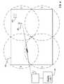
- FIG. 4illustrates a practical example of the method 300 of FIG. 3 .
- every concrete block in a yard 400has an RFID tag coupled thereto or embedded therein.
- Each taghas a unique ID, which is correlated to information about the block and stored in a database.
- informationcan include date of manufacture, composition, manufacturer, the date that the block was brought into the yard, etc.
- Such informationcan also be stored in memory on the tag in addition to in the database, or in the alternative.
- the search systemincludes an interrogator 402 in communication with a backend system 404 , which may include database 406 .
- the interrogator 402is capable of operating in two modes: active (battery powered tag mode, e.g., C3) and passive (backscatter powered tag mode, e.g., C1G2).
- the antenna 403 of the interrogator 402(and potentially the interrogator itself) is attached to a crane that can be lifted high above the yard, thereby potentially communicating with every tag in the yard.
- full poweris used to identify the tags in range, in this case all tags in the yard 400 .
- Singulationis performed to find the tag of interest (target tag 410 ) by matching the tag IDs with a target ID in the database 406 . If the target tag 410 is found, the transmission power is stepped down to reduce the operating range to say, about 1 ⁇ 4 of the size of the yard 400 , thereby dividing the yard into quadrants A, B, C and D.
- the antenna 403is moved by sequentially to each quadrant until the target tag 410 is found. Here, the antenna 403 and the tag of interest 410 are shown in quadrant C.
- the cranethen lowers the antenna into quadrant C and switches to passive mode (even lower range than quadrant search). Several locations of quadrant C are scanned until the target tag 410 is found.
- the transmission poweris again reduced and locations near the place where the target tag was last identified are scanned until the antenna is very near the tag. Then the particular block can be physically identified.
- an inspectorcan scan the blocks with an interrogator in passive mode to ID each block and retrieve the properties of each block from the tag memory or a database.
- the systems and methods provided hereincan also be used to pinpoint the location of a particular block in the building.
- the interrogator(or antenna) can remain active as it moves from quadrants A, B, C and D. In other words, the interrogator continues to scan as it travels along a C-shape path from the center of quadrant A to the center of quadrant D.
- the interrogator (or antenna)can also remain active as it scans sub-parts of each quadrant.
- the effective range of the scanis dependant upon the transmission power of the interrogator.
- the effective rangecan be defined as the maximum range from the interrogator antenna that allows any communication between the interrogator and a tag, reliable communication between the interrogator and a tag as defined by a predefined error rate, etc.
- the effective rangecan also be defined by a distance where a minimum interrogation signal power level is observed. For example, the approximate interrogator signal strength a 10 meters for a given transmitting power level can be estimated. Assuming the area being scanned has a diameter of about 20 meters, the tags can be instructed to not respond to an interrogation signal below that expected at 10 meters at the given power level. In this way, the effective range of the scan is determined by the interrogator power level, and tags outside the particular zone will not respond. This in turn increases efficiency as only the tags in the zone being observed need be singulated and queried.
- FIG. 5illustrates another embodiment of the present invention, where several fixed interrogators 502 , 504 , 506 , 508 (or antennas of a single interrogator) each scan an individual zone Z 1 , Z 2 , Z 3 , Z 4 (with some overlap being acceptable) to determine in which zone the target tag 500 is located. Then some or all operations of the process 300 of FIG. 3 can be performed.
- an interrogator 510or its antenna, set to operate in a range smaller than zone Z 2 is moved to various sub-zones Z 2 A, Z 2 B, Z 2 C, Z 2 D of zone Z 2 until the target tag 500 is found.
- scanning operationsmay be performed entirely in active mode, entirely in passive mode, or a combination of active and passive modes as in the process 300 of FIG. 3 . If a tag falls within two scan areas, as in FIG. 5 , subsequent scans can be directed to the area of overlap to increase speed and efficiency.
Landscapes
- Engineering & Computer Science (AREA)
- Radar, Positioning & Navigation (AREA)
- Remote Sensing (AREA)
- Physics & Mathematics (AREA)
- General Physics & Mathematics (AREA)
- Computer Networks & Wireless Communication (AREA)
- Artificial Intelligence (AREA)
- Computer Vision & Pattern Recognition (AREA)
- Theoretical Computer Science (AREA)
- Radar Systems Or Details Thereof (AREA)
- Near-Field Transmission Systems (AREA)
Abstract
Description
- Passive identity tags (RF user programmable, range ˜3 m)
- Lower cost
- Passive memory tags (20 bit address space programmable at ˜3 m range)
- Security & privacy protection
- Low cost
- Semi-passive tags (also called semi-active tags)
- Battery tags (256 bits to 2 M words)
- Self-Powered Backscatter (internal clock, sensor interface support)
- ˜100 meter range
- Moderate cost
- Active tags
- Active transmission (permits tag-speaks-first operating modes)
- ˜30,000 meter range
- Higher cost
Claims (21)
Priority Applications (3)
| Application Number | Priority Date | Filing Date | Title |
|---|---|---|---|
| US11/423,410US7525434B2 (en) | 2006-06-09 | 2006-06-09 | RF systems and methods for tracking and singulating tagged items |
| PCT/US2007/013239WO2007145945A2 (en) | 2006-06-09 | 2007-06-04 | Rf systems and methods for tracking and singulating tagged items |
| US12/042,818US7800500B2 (en) | 2006-06-09 | 2008-03-05 | RF systems and methods for tracking and singulating tagged items |
Applications Claiming Priority (1)
| Application Number | Priority Date | Filing Date | Title |
|---|---|---|---|
| US11/423,410US7525434B2 (en) | 2006-06-09 | 2006-06-09 | RF systems and methods for tracking and singulating tagged items |
Related Child Applications (1)
| Application Number | Title | Priority Date | Filing Date |
|---|---|---|---|
| US12/042,818ContinuationUS7800500B2 (en) | 2006-06-09 | 2008-03-05 | RF systems and methods for tracking and singulating tagged items |
Publications (2)
| Publication Number | Publication Date |
|---|---|
| US20070285236A1 US20070285236A1 (en) | 2007-12-13 |
| US7525434B2true US7525434B2 (en) | 2009-04-28 |
Family
ID=38821320
Family Applications (2)
| Application Number | Title | Priority Date | Filing Date |
|---|---|---|---|
| US11/423,410Active2027-05-25US7525434B2 (en) | 2006-06-09 | 2006-06-09 | RF systems and methods for tracking and singulating tagged items |
| US12/042,818ActiveUS7800500B2 (en) | 2006-06-09 | 2008-03-05 | RF systems and methods for tracking and singulating tagged items |
Family Applications After (1)
| Application Number | Title | Priority Date | Filing Date |
|---|---|---|---|
| US12/042,818ActiveUS7800500B2 (en) | 2006-06-09 | 2008-03-05 | RF systems and methods for tracking and singulating tagged items |
Country Status (2)
| Country | Link |
|---|---|
| US (2) | US7525434B2 (en) |
| WO (1) | WO2007145945A2 (en) |
Cited By (19)
| Publication number | Priority date | Publication date | Assignee | Title |
|---|---|---|---|---|
| US20080036603A1 (en)* | 2006-08-14 | 2008-02-14 | Savi Technology, Inc. | Method and apparatus for detecting container movement by a crane |
| US20080111702A1 (en)* | 2006-11-14 | 2008-05-15 | Semiconductor Energy Laboratory Co., Ltd. | Semiconductor device |
| US20080150695A1 (en)* | 2006-06-09 | 2008-06-26 | Naresh Batra | Rf systems and methods for tracking and singulating tagged items |
| US20080186177A1 (en)* | 2007-02-05 | 2008-08-07 | Intermec Ip Corp. | Encoding apparatus and method of using the same |
| US20080266096A1 (en)* | 2007-04-27 | 2008-10-30 | Hanns-Christian Leemon Hanebeck | Method and System Using RFID Tags for Triggering Document Generation |
| US20080266095A1 (en)* | 2007-04-27 | 2008-10-30 | Hanns-Christian Leemon Hanebeck | Method and System Using RFID Tags for Initiation of Selected Business Processes |
| US20080266094A1 (en)* | 2007-04-27 | 2008-10-30 | Hanns-Christian Leemon Hanebeck | Method and System Using RFID Tags for System Re-configuration |
| US20090303047A1 (en)* | 2008-06-10 | 2009-12-10 | Symbol Technologies, Inc. | Methods and Systems for Tracking RFID Devices |
| US20100127874A1 (en)* | 2008-11-21 | 2010-05-27 | Curtis Guy P | Information locator |
| US20110043358A1 (en)* | 2009-08-20 | 2011-02-24 | Airpointe Of New Hampshire, Inc. | Position locating by polyhedral morphing |
| US20110166937A1 (en)* | 2010-01-05 | 2011-07-07 | Searete Llc | Media output with micro-impulse radar feedback of physiological response |
| US20110166940A1 (en)* | 2010-01-05 | 2011-07-07 | Searete Llc | Micro-impulse radar detection of a human demographic and delivery of targeted media content |
| US20110285579A1 (en)* | 2010-01-05 | 2011-11-24 | Searete Llc | Tracking identities of persons using micro-impulse radar |
| US8884813B2 (en) | 2010-01-05 | 2014-11-11 | The Invention Science Fund I, Llc | Surveillance of stress conditions of persons using micro-impulse radar |
| US9019149B2 (en) | 2010-01-05 | 2015-04-28 | The Invention Science Fund I, Llc | Method and apparatus for measuring the motion of a person |
| US9069067B2 (en) | 2010-09-17 | 2015-06-30 | The Invention Science Fund I, Llc | Control of an electronic apparatus using micro-impulse radar |
| US12223383B2 (en) | 2020-03-18 | 2025-02-11 | Duke Manufacturing Co. | Smart food pan system |
| US12318035B2 (en) | 2020-03-18 | 2025-06-03 | Duke Manufacturing Co. | Networked food preparation apparatus |
| US12418435B2 (en) | 2020-03-18 | 2025-09-16 | Duke Manufacturing Co. | Networked food preparation apparatus |
Families Citing this family (19)
| Publication number | Priority date | Publication date | Assignee | Title |
|---|---|---|---|---|
| US8270911B2 (en)* | 2007-02-28 | 2012-09-18 | Round Rock Research, Llc | Communications methods, methods of forming a reader, wireless communications readers, and wireless communications systems |
| US8421627B2 (en)* | 2008-08-21 | 2013-04-16 | Symbol Technologies, Inc. | Method for associating and RFID tag with a known region |
| US8456306B2 (en)* | 2008-12-17 | 2013-06-04 | Symbol Technologies, Inc. | Association based locationing for RFID |
| US8029212B2 (en) | 2009-07-29 | 2011-10-04 | Pevco Systems International, Inc. | Method and system for sealing products in a pneumatic tube carrier |
| SG182310A1 (en)* | 2010-01-05 | 2012-08-30 | Agency Science Tech & Res | System and method of tracking objects |
| CN102103680B (en)* | 2010-08-17 | 2014-09-10 | 中兴通讯股份有限公司 | Method for positioning and identifying electronic tag, reader and positioning system |
| US20130162402A1 (en)* | 2011-12-27 | 2013-06-27 | Mathias Amann | Apparatus and Method for Providing Product Information |
| US20160078264A1 (en)* | 2012-05-07 | 2016-03-17 | Senitron Corp. | Real time electronic article surveillance and management |
| US9245160B2 (en)* | 2013-08-20 | 2016-01-26 | Qualcomm Technologies International, Ltd. | Method for setting up a beacon network inside a retail environment |
| US9998859B2 (en) | 2014-02-25 | 2018-06-12 | Bridgewest Finance Llc | Systems and methods of location and tracking |
| US10132917B2 (en)* | 2014-02-25 | 2018-11-20 | Bridgewest Finance Llc | Systems and methods of location and tracking |
| CA2990169A1 (en) | 2015-06-19 | 2016-12-22 | Lawrence Hutch DOUGLAS | Systems and methods for mobile device-based item acquisition and tracking |
| CN106651104B (en)* | 2016-10-19 | 2020-06-23 | 国网山东省电力公司烟台供电公司 | An RFID-based intelligent warning device for power work sites |
| WO2019144054A1 (en)* | 2018-01-19 | 2019-07-25 | Johnson Controls Technology Company | Hand hygiene and surgical scrub system |
| US10762307B2 (en)* | 2018-07-25 | 2020-09-01 | Argox Information Co., Ltd. | Terminal, cargo tag and cargo management system and processing methods thereof |
| WO2020064067A1 (en)* | 2018-09-28 | 2020-04-02 | Valify Aps | A system and method for validating a product |
| FR3093210B1 (en)* | 2019-02-27 | 2021-02-19 | Greenerwave | Receiver detection system |
| JP2023082574A (en)* | 2021-12-02 | 2023-06-14 | 東芝テック株式会社 | Selection device and information processing system |
| JP2023082577A (en)* | 2021-12-02 | 2023-06-14 | 東芝テック株式会社 | Communication device |
Citations (21)
| Publication number | Priority date | Publication date | Assignee | Title |
|---|---|---|---|---|
| US5689238A (en) | 1996-03-08 | 1997-11-18 | Lucent Technologies, Inc. | Object locator system and methods therefor |
| US20020008140A1 (en) | 1999-09-21 | 2002-01-24 | Reynolds Andrew E. | Method and apparatus to perform a predefined search on data carriers, such as RFID tags |
| US6353406B1 (en) | 1996-10-17 | 2002-03-05 | R.F. Technologies, Inc. | Dual mode tracking system |
| US6354493B1 (en)* | 1999-12-23 | 2002-03-12 | Sensormatic Electronics Corporation | System and method for finding a specific RFID tagged article located in a plurality of RFID tagged articles |
| US6552661B1 (en)* | 2000-08-25 | 2003-04-22 | Rf Code, Inc. | Zone based radio frequency identification |
| US6600418B2 (en) | 2000-12-12 | 2003-07-29 | 3M Innovative Properties Company | Object tracking and management system and method using radio-frequency identification tags |
| US6727803B2 (en) | 2001-03-16 | 2004-04-27 | E-Tag Systems, Inc. | Method and apparatus for efficiently querying and identifying multiple items on a communication channel |
| WO2004038644A2 (en) | 2002-10-25 | 2004-05-06 | Symbol Technologies, Inc. | Optimization of a binary tree traversal with secure communications |
| US6774766B1 (en) | 2000-07-21 | 2004-08-10 | E-Tag Systems, Inc. | Method for efficiently querying and identifying multiple items on a communication channel |
| US20040201454A1 (en) | 2003-04-09 | 2004-10-14 | Paul Waterhouse | Networked RF tag for tracking freight |
| US20050057341A1 (en) | 2003-09-17 | 2005-03-17 | Roesner Bruce B. | Deep sleep in an RFID tag |
| US20050198228A1 (en) | 2004-02-13 | 2005-09-08 | Bajwa Raminder S. | Radio frequency identification (RFID) network system and method |
| US20050206555A1 (en) | 2004-03-16 | 2005-09-22 | Raj Bridgelall | Multi-resolution object location system and method |
| US20050237157A1 (en) | 2004-04-13 | 2005-10-27 | Impinj, Inc. | RFID tag systems, RFID tags and RFID processes with branch node indexing |
| US20050237159A1 (en) | 2004-04-13 | 2005-10-27 | Impinj, Inc. | RFID tag systems, RFID tags and RFID processes with reverse link burst mode |
| US20050237158A1 (en) | 2004-04-13 | 2005-10-27 | Impinj, Inc. | RFID tag systems, RFID tags and RFID processes using N-ary FSK |
| US20060055552A1 (en) | 2004-08-26 | 2006-03-16 | Chung Kevin K | RFID device for object monitoring, locating, and tracking |
| US20060214773A1 (en)* | 2005-02-10 | 2006-09-28 | Psc Scanning, Inc. | RFID tag singulation |
| US20060284727A1 (en)* | 2005-06-16 | 2006-12-21 | Psc Scanning, Inc. | Method and system with functionality for finding range between an electronic tag reader and tag |
| US20070257776A1 (en)* | 2006-04-28 | 2007-11-08 | Symbol Technologies, Inc. | Verification of singulated RFID tags by RFID readers |
| US20080001725A1 (en)* | 2006-06-28 | 2008-01-03 | Symbol Technologies, Inc. | Read locking of an RFID tag |
Family Cites Families (2)
| Publication number | Priority date | Publication date | Assignee | Title |
|---|---|---|---|---|
| US6552261B2 (en)* | 2001-04-27 | 2003-04-22 | Bmi, Inc. | Push-fit shield |
| US7525434B2 (en)* | 2006-06-09 | 2009-04-28 | Intelleflex Corporation | RF systems and methods for tracking and singulating tagged items |
- 2006
- 2006-06-09USUS11/423,410patent/US7525434B2/enactiveActive
- 2007
- 2007-06-04WOPCT/US2007/013239patent/WO2007145945A2/enactiveApplication Filing
- 2008
- 2008-03-05USUS12/042,818patent/US7800500B2/enactiveActive
Patent Citations (23)
| Publication number | Priority date | Publication date | Assignee | Title |
|---|---|---|---|---|
| US5689238A (en) | 1996-03-08 | 1997-11-18 | Lucent Technologies, Inc. | Object locator system and methods therefor |
| US6353406B1 (en) | 1996-10-17 | 2002-03-05 | R.F. Technologies, Inc. | Dual mode tracking system |
| US20020008140A1 (en) | 1999-09-21 | 2002-01-24 | Reynolds Andrew E. | Method and apparatus to perform a predefined search on data carriers, such as RFID tags |
| US6354493B1 (en)* | 1999-12-23 | 2002-03-12 | Sensormatic Electronics Corporation | System and method for finding a specific RFID tagged article located in a plurality of RFID tagged articles |
| US6774766B1 (en) | 2000-07-21 | 2004-08-10 | E-Tag Systems, Inc. | Method for efficiently querying and identifying multiple items on a communication channel |
| US20050007240A1 (en) | 2000-07-21 | 2005-01-13 | Moyer Norman E. | Method for efficiently querying and identifying multiple items on a communication channel |
| US6552661B1 (en)* | 2000-08-25 | 2003-04-22 | Rf Code, Inc. | Zone based radio frequency identification |
| US6600418B2 (en) | 2000-12-12 | 2003-07-29 | 3M Innovative Properties Company | Object tracking and management system and method using radio-frequency identification tags |
| US6727803B2 (en) | 2001-03-16 | 2004-04-27 | E-Tag Systems, Inc. | Method and apparatus for efficiently querying and identifying multiple items on a communication channel |
| WO2004038644A2 (en) | 2002-10-25 | 2004-05-06 | Symbol Technologies, Inc. | Optimization of a binary tree traversal with secure communications |
| US20040201454A1 (en) | 2003-04-09 | 2004-10-14 | Paul Waterhouse | Networked RF tag for tracking freight |
| US20050057341A1 (en) | 2003-09-17 | 2005-03-17 | Roesner Bruce B. | Deep sleep in an RFID tag |
| US20050198228A1 (en) | 2004-02-13 | 2005-09-08 | Bajwa Raminder S. | Radio frequency identification (RFID) network system and method |
| US7030761B2 (en)* | 2004-03-16 | 2006-04-18 | Symbol Technologies | Multi-resolution object location system and method |
| US20050206555A1 (en) | 2004-03-16 | 2005-09-22 | Raj Bridgelall | Multi-resolution object location system and method |
| US20050237157A1 (en) | 2004-04-13 | 2005-10-27 | Impinj, Inc. | RFID tag systems, RFID tags and RFID processes with branch node indexing |
| US20050237158A1 (en) | 2004-04-13 | 2005-10-27 | Impinj, Inc. | RFID tag systems, RFID tags and RFID processes using N-ary FSK |
| US20050237159A1 (en) | 2004-04-13 | 2005-10-27 | Impinj, Inc. | RFID tag systems, RFID tags and RFID processes with reverse link burst mode |
| US20060055552A1 (en) | 2004-08-26 | 2006-03-16 | Chung Kevin K | RFID device for object monitoring, locating, and tracking |
| US20060214773A1 (en)* | 2005-02-10 | 2006-09-28 | Psc Scanning, Inc. | RFID tag singulation |
| US20060284727A1 (en)* | 2005-06-16 | 2006-12-21 | Psc Scanning, Inc. | Method and system with functionality for finding range between an electronic tag reader and tag |
| US20070257776A1 (en)* | 2006-04-28 | 2007-11-08 | Symbol Technologies, Inc. | Verification of singulated RFID tags by RFID readers |
| US20080001725A1 (en)* | 2006-06-28 | 2008-01-03 | Symbol Technologies, Inc. | Read locking of an RFID tag |
Non-Patent Citations (1)
| Title |
|---|
| Search Report and Written Opinion from PCT Application No. PCT/US07/13239 mailed Jan. 18, 2008. |
Cited By (30)
| Publication number | Priority date | Publication date | Assignee | Title |
|---|---|---|---|---|
| US7800500B2 (en)* | 2006-06-09 | 2010-09-21 | Intelleflex Corporation | RF systems and methods for tracking and singulating tagged items |
| US20080150695A1 (en)* | 2006-06-09 | 2008-06-26 | Naresh Batra | Rf systems and methods for tracking and singulating tagged items |
| US8264331B2 (en)* | 2006-08-14 | 2012-09-11 | Savi Technology, Inc. | Method and apparatus for detecting container movement by a crane |
| US20080036603A1 (en)* | 2006-08-14 | 2008-02-14 | Savi Technology, Inc. | Method and apparatus for detecting container movement by a crane |
| US8044800B2 (en)* | 2006-11-14 | 2011-10-25 | Semiconductor Energy Laboratory Co., Ltd. | Semiconductor device |
| US8319645B2 (en) | 2006-11-14 | 2012-11-27 | Semiconductor Energy Laboratory Co., Ltd. | Semiconductor device |
| US20080111702A1 (en)* | 2006-11-14 | 2008-05-15 | Semiconductor Energy Laboratory Co., Ltd. | Semiconductor device |
| US20080186177A1 (en)* | 2007-02-05 | 2008-08-07 | Intermec Ip Corp. | Encoding apparatus and method of using the same |
| US20080266094A1 (en)* | 2007-04-27 | 2008-10-30 | Hanns-Christian Leemon Hanebeck | Method and System Using RFID Tags for System Re-configuration |
| US20080266096A1 (en)* | 2007-04-27 | 2008-10-30 | Hanns-Christian Leemon Hanebeck | Method and System Using RFID Tags for Triggering Document Generation |
| US20080266095A1 (en)* | 2007-04-27 | 2008-10-30 | Hanns-Christian Leemon Hanebeck | Method and System Using RFID Tags for Initiation of Selected Business Processes |
| US8207828B2 (en) | 2007-04-27 | 2012-06-26 | International Business Machines Corporation | Method and system using RFID tags for system re-configuration |
| US8203435B2 (en) | 2007-04-27 | 2012-06-19 | International Business Machines Corporation | Triggering document generation using RFID tags |
| US8169303B2 (en)* | 2007-04-27 | 2012-05-01 | International Business Machines Corporation | Method and system using RFID tags for initiation of selected business processes |
| US8120486B2 (en)* | 2008-06-10 | 2012-02-21 | Symbol Technologies, Inc. | Methods and systems for tracking RFID devices |
| US20090303047A1 (en)* | 2008-06-10 | 2009-12-10 | Symbol Technologies, Inc. | Methods and Systems for Tracking RFID Devices |
| US20100127874A1 (en)* | 2008-11-21 | 2010-05-27 | Curtis Guy P | Information locator |
| WO2011022568A3 (en)* | 2009-08-20 | 2011-06-16 | Consortium P, Inc. | Position locating by polyhedral morphing |
| US8077031B2 (en)* | 2009-08-20 | 2011-12-13 | Consortium P, Inc. | Position locating by polyhedral morphing |
| US20110043358A1 (en)* | 2009-08-20 | 2011-02-24 | Airpointe Of New Hampshire, Inc. | Position locating by polyhedral morphing |
| US20110285579A1 (en)* | 2010-01-05 | 2011-11-24 | Searete Llc | Tracking identities of persons using micro-impulse radar |
| US20110166940A1 (en)* | 2010-01-05 | 2011-07-07 | Searete Llc | Micro-impulse radar detection of a human demographic and delivery of targeted media content |
| US20110166937A1 (en)* | 2010-01-05 | 2011-07-07 | Searete Llc | Media output with micro-impulse radar feedback of physiological response |
| US8884813B2 (en) | 2010-01-05 | 2014-11-11 | The Invention Science Fund I, Llc | Surveillance of stress conditions of persons using micro-impulse radar |
| US9019149B2 (en) | 2010-01-05 | 2015-04-28 | The Invention Science Fund I, Llc | Method and apparatus for measuring the motion of a person |
| US9024814B2 (en)* | 2010-01-05 | 2015-05-05 | The Invention Science Fund I, Llc | Tracking identities of persons using micro-impulse radar |
| US9069067B2 (en) | 2010-09-17 | 2015-06-30 | The Invention Science Fund I, Llc | Control of an electronic apparatus using micro-impulse radar |
| US12223383B2 (en) | 2020-03-18 | 2025-02-11 | Duke Manufacturing Co. | Smart food pan system |
| US12318035B2 (en) | 2020-03-18 | 2025-06-03 | Duke Manufacturing Co. | Networked food preparation apparatus |
| US12418435B2 (en) | 2020-03-18 | 2025-09-16 | Duke Manufacturing Co. | Networked food preparation apparatus |
Also Published As
| Publication number | Publication date |
|---|---|
| US7800500B2 (en) | 2010-09-21 |
| US20080150695A1 (en) | 2008-06-26 |
| US20070285236A1 (en) | 2007-12-13 |
| WO2007145945A2 (en) | 2007-12-21 |
| WO2007145945A3 (en) | 2008-03-20 |
Similar Documents
| Publication | Publication Date | Title |
|---|---|---|
| US7525434B2 (en) | RF systems and methods for tracking and singulating tagged items | |
| US8098159B2 (en) | RF device comparing DAC output to incoming signal for selectively performing an action | |
| US8570172B2 (en) | RFID system with distributed transmitters | |
| US9087226B2 (en) | System, method and computer program product for calibrating interrogator signal strength and/or tag response range setting | |
| US11803724B2 (en) | Starting a vehicle using a device | |
| US7561107B2 (en) | RFID device with microstrip antennas | |
| EP2377076B1 (en) | Method and system for item level uhf rfid tag with low frequency power assist | |
| US8077012B2 (en) | RFID device with first clock for data acquisition and/or calibration of second clock | |
| US9082057B2 (en) | RF device with tamper detection | |
| US8026819B2 (en) | Radio tag and system | |
| US20070290791A1 (en) | Rfid-based security systems and methods | |
| US8717144B2 (en) | RFID system with distributed readers | |
| US20080062046A1 (en) | Mounting structure for matching an rf integrated circuit with an antenna and rfid device implementing same | |
| Bachu et al. | A Review of RFID Technology | |
| Miller | RFID: What’s it all about? |
Legal Events
| Date | Code | Title | Description |
|---|---|---|---|
| AS | Assignment | Owner name:INTELLEFLEX CORPORATION, CALIFORNIA Free format text:ASSIGNMENT OF ASSIGNORS INTEREST;ASSIGNOR:BATRA, NARESH;REEL/FRAME:018234/0531 Effective date:20060607 | |
| AS | Assignment | Owner name:VENTURE LENDING & LEASING IV, INC. AS AGENT, CALIF Free format text:SECURITY INTEREST;ASSIGNOR:INTELLEFLEX CORPORATION;REEL/FRAME:020955/0628 Effective date:20080422 Owner name:VENTURE LENDING & LEASING IV, INC. AS AGENT,CALIFO Free format text:SECURITY INTEREST;ASSIGNOR:INTELLEFLEX CORPORATION;REEL/FRAME:020955/0628 Effective date:20080422 | |
| AS | Assignment | Owner name:VENTURE LENDING & LEASING V, INC., AS AGENT, CALIF Free format text:SECURITY AGREEMENT;ASSIGNOR:INTELLEFLEX CORPORATION;REEL/FRAME:020960/0279 Effective date:20080422 Owner name:VENTURE LENDING & LEASING V, INC., AS AGENT,CALIFO Free format text:SECURITY AGREEMENT;ASSIGNOR:INTELLEFLEX CORPORATION;REEL/FRAME:020960/0279 Effective date:20080422 | |
| STCF | Information on status: patent grant | Free format text:PATENTED CASE | |
| CC | Certificate of correction | ||
| FPAY | Fee payment | Year of fee payment:4 | |
| FPAY | Fee payment | Year of fee payment:8 | |
| AS | Assignment | Owner name:ZEST LABS, INC., CALIFORNIA Free format text:CHANGE OF NAME;ASSIGNOR:INTELLEFLEX CORPORATION;REEL/FRAME:041678/0799 Effective date:20161027 | |
| MAFP | Maintenance fee payment | Free format text:PAYMENT OF MAINTENANCE FEE, 12TH YEAR, LARGE ENTITY (ORIGINAL EVENT CODE: M1553); ENTITY STATUS OF PATENT OWNER: LARGE ENTITY Year of fee payment:12 | |
| AS | Assignment | Owner name:WELLS FARGO BANK, NATIONAL ASSOCIATION, AS ADMINISTRATIVE AGENT, CALIFORNIA Free format text:SECURITY INTEREST;ASSIGNORS:NEXTIVA, INC.;THRIO, INC.;REEL/FRAME:067172/0404 Effective date:20240419 |