US7525422B2 - Method and system for providing alarm reporting in a managed network services environment - Google Patents
Method and system for providing alarm reporting in a managed network services environmentDownload PDFInfo
- Publication number
- US7525422B2 US7525422B2US11/404,503US40450306AUS7525422B2US 7525422 B2US7525422 B2US 7525422B2US 40450306 AUS40450306 AUS 40450306AUS 7525422 B2US7525422 B2US 7525422B2
- Authority
- US
- United States
- Prior art keywords
- alarm
- feed
- network
- ticket
- customer
- Prior art date
- Legal status (The legal status is an assumption and is not a legal conclusion. Google has not performed a legal analysis and makes no representation as to the accuracy of the status listed.)
- Expired - Fee Related, expires
Links
- 238000000034methodMethods0.000titleclaimsdescription125
- 238000012423maintenanceMethods0.000claimsdescription66
- 238000012544monitoring processMethods0.000claimsdescription18
- 230000004044responseEffects0.000claimsdescription10
- 230000000875corresponding effectEffects0.000claimsdescription8
- 238000011084recoveryMethods0.000claimsdescription6
- 230000002596correlated effectEffects0.000claimsdescription3
- 238000013459approachMethods0.000abstractdescription4
- 230000008569processEffects0.000description97
- 238000007726management methodMethods0.000description89
- 238000012360testing methodMethods0.000description84
- 238000004458analytical methodMethods0.000description39
- 238000004891communicationMethods0.000description28
- 230000000694effectsEffects0.000description26
- 238000012545processingMethods0.000description26
- 238000002955isolationMethods0.000description24
- 230000009471actionEffects0.000description21
- 230000008439repair processEffects0.000description15
- 230000006870functionEffects0.000description10
- 238000013515scriptMethods0.000description10
- 238000013507mappingMethods0.000description8
- 230000003287optical effectEffects0.000description8
- 230000008030eliminationEffects0.000description7
- 238000003379elimination reactionMethods0.000description7
- 238000003745diagnosisMethods0.000description6
- 230000003993interactionEffects0.000description6
- 238000012790confirmationMethods0.000description5
- 230000008520organizationEffects0.000description5
- 230000007704transitionEffects0.000description5
- 238000013070change managementMethods0.000description4
- 238000010586diagramMethods0.000description4
- 230000005540biological transmissionEffects0.000description3
- 238000013480data collectionMethods0.000description3
- 238000013461designMethods0.000description3
- 238000005516engineering processMethods0.000description3
- 230000007246mechanismEffects0.000description3
- 238000012546transferMethods0.000description3
- 230000008901benefitEffects0.000description2
- 239000000969carrierSubstances0.000description2
- 230000008859changeEffects0.000description2
- 230000001276controlling effectEffects0.000description2
- 238000001514detection methodMethods0.000description2
- 230000036541healthEffects0.000description2
- 230000000977initiatory effectEffects0.000description2
- 238000005192partitionMethods0.000description2
- 230000000737periodic effectEffects0.000description2
- 230000003068static effectEffects0.000description2
- 238000012795verificationMethods0.000description2
- RYGMFSIKBFXOCR-UHFFFAOYSA-NCopperChemical compound[Cu]RYGMFSIKBFXOCR-UHFFFAOYSA-N0.000description1
- 208000031361HiccupDiseases0.000description1
- 238000003491arrayMethods0.000description1
- 238000012550auditMethods0.000description1
- 238000013475authorizationMethods0.000description1
- 238000004422calculation algorithmMethods0.000description1
- 238000012508change requestMethods0.000description1
- 230000008878couplingEffects0.000description1
- 238000010168coupling processMethods0.000description1
- 238000005859coupling reactionMethods0.000description1
- 230000001419dependent effectEffects0.000description1
- 239000000835fiberSubstances0.000description1
- 230000004941influxEffects0.000description1
- 230000010354integrationEffects0.000description1
- 230000002452interceptive effectEffects0.000description1
- 230000002045lasting effectEffects0.000description1
- 239000004973liquid crystal related substanceSubstances0.000description1
- 230000007774longtermEffects0.000description1
- 239000011159matrix materialSubstances0.000description1
- 230000000116mitigating effectEffects0.000description1
- 238000012986modificationMethods0.000description1
- 230000004048modificationEffects0.000description1
- 238000003012network analysisMethods0.000description1
- 230000002093peripheral effectEffects0.000description1
- 230000002085persistent effectEffects0.000description1
- 238000007781pre-processingMethods0.000description1
- 230000009467reductionEffects0.000description1
- 230000001105regulatory effectEffects0.000description1
- 238000012552reviewMethods0.000description1
- 230000035945sensitivityEffects0.000description1
- 230000011664signalingEffects0.000description1
- 238000013068supply chain managementMethods0.000description1
- 208000024891symptomDiseases0.000description1
- 230000001360synchronised effectEffects0.000description1
- 230000001960triggered effectEffects0.000description1
- 238000013024troubleshootingMethods0.000description1
- 239000011800void materialSubstances0.000description1
Images


Classifications
- H—ELECTRICITY
- H04—ELECTRIC COMMUNICATION TECHNIQUE
- H04M—TELEPHONIC COMMUNICATION
- H04M3/00—Automatic or semi-automatic exchanges
- H04M3/08—Indicating faults in circuits or apparatus
- H04M3/10—Providing fault- or trouble-signals
- H—ELECTRICITY
- H04—ELECTRIC COMMUNICATION TECHNIQUE
- H04L—TRANSMISSION OF DIGITAL INFORMATION, e.g. TELEGRAPHIC COMMUNICATION
- H04L41/00—Arrangements for maintenance, administration or management of data switching networks, e.g. of packet switching networks
- H04L41/06—Management of faults, events, alarms or notifications
- H04L41/0631—Management of faults, events, alarms or notifications using root cause analysis; using analysis of correlation between notifications, alarms or events based on decision criteria, e.g. hierarchy, tree or time analysis
- H—ELECTRICITY
- H04—ELECTRIC COMMUNICATION TECHNIQUE
- H04M—TELEPHONIC COMMUNICATION
- H04M3/00—Automatic or semi-automatic exchanges
- H04M3/22—Arrangements for supervision, monitoring or testing
- H04M3/2254—Arrangements for supervision, monitoring or testing in networks
- H—ELECTRICITY
- H04—ELECTRIC COMMUNICATION TECHNIQUE
- H04L—TRANSMISSION OF DIGITAL INFORMATION, e.g. TELEGRAPHIC COMMUNICATION
- H04L41/00—Arrangements for maintenance, administration or management of data switching networks, e.g. of packet switching networks
- H04L41/02—Standardisation; Integration
- H04L41/0233—Object-oriented techniques, for representation of network management data, e.g. common object request broker architecture [CORBA]
- H—ELECTRICITY
- H04—ELECTRIC COMMUNICATION TECHNIQUE
- H04L—TRANSMISSION OF DIGITAL INFORMATION, e.g. TELEGRAPHIC COMMUNICATION
- H04L41/00—Arrangements for maintenance, administration or management of data switching networks, e.g. of packet switching networks
- H04L41/06—Management of faults, events, alarms or notifications
- H04L41/0654—Management of faults, events, alarms or notifications using network fault recovery
- H04L41/0659—Management of faults, events, alarms or notifications using network fault recovery by isolating or reconfiguring faulty entities
Definitions
- Network monitoringinvolves receiving and interpreting a multitude of alarms that are assigned to various network components. These alarms are triggered when anomalies are detected in their respective components. Monitoring systems provide these alarms in the form of reports for network analysis (or network monitors) to analyze the cause of the network anomaly and to manually initiate action to resolve the cause. Such resolution can also entail manually interfacing with multiple disparate systems.
- the number of alarmscan be unmanageable. That is, the network monitors may be inundated periodically with alarm reports stemming from a major network problem, or even a series of small anomalies arising within a short time span. These events can thus trigger a tremendous volume of alarm reports, which can overwhelm the network surveillance engineers and hamper the process of restoring the network. Reducing the restoration time per network event can translate into significant savings to the customer.
- network surveillance engineersreceive alarm reports from the telecommunications network and then manually process these alarm reports. Processing an alarm report involves an orderly procedure for resolving the anomaly that generated an alarm.
- the processing of alarm reports to resolve network anomaliescan require retrieving network parameter information, such as equipment operating characteristics from paper manuals; consulting telephone directories to find telephone numbers for remote network sites; collection configuration information from the network equipment associated with the trouble; and completing electronic telecommunications trouble forms, referred to as trouble tickets or service reports.
- a network surveillance engineerprepares a trouble ticket (or service report) when action by a field engineer appears necessary. Field engineers are typically telecommunications personnel who service the telecommunications network (e.g., replacing a faulty component at a specific location).
- FIGS. 1A-1Eare diagrams, respectively, of a managed services system for providing fault isolation and alarm reporting, according to various embodiments of the present invention
- FIGS. 2A and 2Bare flowcharts, respectively, of a fault isolation process performed as a managed service and of an alarm and maintenance event correlation process used in the fault isolation process, according to various embodiments of the present invention
- FIGS. 3A-3Eare a flowchart of an automation process for fault handling, according to one embodiment of the present invention.
- FIG. 4is a flowchart of a notification process, according to an embodiment of the present invention.
- FIG. 5is a flowchart of a data collection process, according to one embodiment of the present invention.
- FIGS. 6A-6Dare a flowchart of a process for fault testing, according to an embodiment of the present invention.
- FIG. 7is a flowchart of a process for network monitoring, according to an embodiment of the present invention.
- FIG. 8is a diagram of a computer system that can be used to implement an embodiment of the present invention.
- FIGS. 1A-1Eare diagrams, respectively, of a managed services system for providing fault isolation and alarm reporting, according to various embodiments of the present invention.
- a managed services system 100(shown in FIG. 1A ) employs a workflow application, as executed by an integrated network management platform 101 , to automate many of the initial actions needed in response to a fault alarm affecting a managed network.
- the system 100possesses an automation architecture, which is more fully described below with respect to FIG. 2 , for collection and pre-processing of alarm information using an external process.
- the automation process(or engine) gathers topology and customer specific information for use in reacting to the alarm. Conditional invocation of automation based on customer preferences is supported.
- An automation “script”can be applied depending on the nature of the alarm.
- the automation enginealso communicates with maintenance and trouble ticket management systems to determine correlation of the fault alarm. Additionally, automatic initiation of data retrieval and testing services, which can be subject to customer preferences and the nature of the alarm, are supported. Further, the system 100 provides automatic reporting of status of the automated process to various users (e.g., surveillance engineer and customer); the customer has the capability to dynamically specify when and how they are to be contacted. A monitor service for continual monitoring and reporting on the alarm state is offered by the system, whereby trouble tickets can be re-opened, and the automation process re-initiated as needed.
- userse.g., surveillance engineer and customer
- a monitor service for continual monitoring and reporting on the alarm stateis offered by the system, whereby trouble tickets can be re-opened, and the automation process re-initiated as needed.
- fault isolation and network resolution/recovery capabilitiesare described as a managed service offered by a network service provider (e.g., a carrier) in the system 100 .
- a network service providere.g., a carrier
- network service providerscompared to customer organizations, have greater end-to-end view of communications because they control the backbone. Consequently, these service providers can identify network events and isolate faults quickly, without having to “wait” for assistance or resolution by other parties, regardless of whether the problem occurs in the customer network, an access link, or the core network.
- the integrated network management platform 101can serve one or more customer networks, such as network 103 .
- the integrated network management platform 101interfaces with various element management and network management systems to provide a unified view of network problems to the network management personnel.
- the platform 101provides numerous features that can enhance productivity for the network analyst. These features, for example, include workflow, ticketing, topology information, task automation, command interaction capabilities, as well as interfaces to several internal systems for maintenance activities, outage notifications, and contact information.
- the integrated network management platform 101accordingly can serve as a global account manager to provide user authentication services, including a single sign-on capability as well as workstation independence. Access privileges and configurable application data for save/restore user session profiles are also supported.
- the platform 101additionally provides a common repository for user, group, application, and resource data, along with the associated security settings, and an Application Programming Interface (API) for managing a variety of information.
- the platform 101can adopt network security policies, and support automated application updates. Further, the integrated network management platform 101 provides a front-end web portal, according to one embodiment of the present invention.
- the platform 101has a JAVA® 2 Enterprise Edition (J2EE) application framework to leverage its support for database connectivity, transaction processing, and directory services in a reliable and secure environment.
- J2EEJAVA® 2 Enterprise Edition
- the customer (or managed) network 103can be an enterprise network providing voice and/or data services for the enterprise.
- the customer network 103can be an Internet Protocol (IP)-based network supporting data communication as well as IP telephony; it is noted any variety of local area network (LAN) and wide area network (WAN) technologies can be deployed within the network 103 —e.g., Asynchronous Transfer Mode (ATM), Ethernet-based, etc.
- IPInternet Protocol
- LANlocal area network
- WANwide area network
- ATMAsynchronous Transfer Mode
- Ethernet-basedetc.
- the management platform 101On the service provider side, the management platform 101 has access to a customer network inventory database 105 , which stores information (as necessary for performing fault isolation) about the network components of the customer network 103 .
- the management platform 101interfaces with various systems, including a maintenance management system 107 , a network testing system 109 , and a trouble management system 111 .
- the platform 101thus, provides the ability to discover or store the topology of the customer network 103 , review alarms/events on the network 103 , eliminate events from consideration due to pre-determined maintenance windows and correlate the alarms into significant events.
- the management platform 101supports an automation engine that engages the appropriate test scripts based upon the event to further isolate the problem.
- Customer Premise Equipment (CPE) of the network 103are polled (through, for example, out-of-band access if connectivity has been lost), and test points across the network 103 as well as the backbone network (not shown) are checked at all appropriate locations including at a Local Exchange Carrier (LEC) network.
- LECLocal Exchange Carrier
- GUIgraphical user interface
- the customerwould have to perform a number of manual steps. For example, the administrator would need to view all the alarms across the network, and correlate the alarms into distinguishing events (i.e., topology correlation). Also, the administrator may need to obtain information from the network components by dialing out-of-band into a CPE to evaluate the health of the CPE. If the CPE is not the cause of the fault, the administrator can then contact the circuit provider to explain the problem and to identify the troubled location/site. The circuit provider may subsequently open a trouble ticket for handling by a field technician. The technician can then initiate the appropriate tests to diagnose the fault. At this point, there can be confusion regarding who is responsible for the problem.
- the integrated network management platform 101can provide personnel of the service provider with a central tool that automates numerous functions for the technician. These functions can include fault detection and root cause determination for CPE reported failures; customer and circuit identification; trouble ticket creation, update and closure; and maintenance check. Also, the functions can include end-to-end alarm correlation and testing, for example, based upon circuit identifiers (IDs); ticket referral; fix verification (alarm clear and ticket refer-back); and customer notification and interaction.
- IDscircuit identifiers
- ticket referralticket referral
- fix verificationalarm clear and ticket refer-back
- customer notification and interactioncustomer notification and interaction.
- the platform 101enables an integrated, automated approach to fault isolation and resolution.
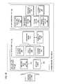
- the platform 101possesses an automation architecture 151 comprising three tiers: a fault analysis and elimination tier 153 , a fault processing tier 155 , and a repair management tier 157 .
- the fault analysis and elimination tier 153 of the architectureeffectively provides a user interface (e.g., graphical user interfaces (GUIs)) via a real-time management and analysis module 153 a and a services portal 153 b .
- GUIsgraphical user interfaces
- This tier 153provides GUIs that are used to interact with alarms, tickets, and workflow events that exist within the system 100 .
- Tier 153also has the ability to call web links directly to both the systems of the repair management tier 157 as well as other business processes, which can provide access to detailed information and business functions when needed.
- the services portal 153 bprovides an interface to the customer for the following capabilities: project management, order management, change management, network management, activity completion reporting and service provisioning for managed services.
- the portal 153 bcan possess an associated database (not shown) for managed services customer premise equipment as well as, for example, related customer contact data, IP addresses, operations process and service level agreements, maintenance agreements, etc.
- the services portal 153 bis also capable of receiving service order information.
- the portal 153 bmaintains knowledge of related circuit connections corresponding to the managed CPE. Alternate carrier circuit information is also supported.
- the services portal 153 bemploys a web services extensible Mark-up Language (XML) interface.
- XMLweb services extensible Mark-up Language
- This interfacecan provide access to services portal data, including customer and site contact information, procedures at customer and site level, CPE detail, circuit numbers, change management activities, IP addressing, alert status, etc.
- the services portal 153 bcan accommodate network devices that are shared by multiple customers to support services, such as virtual routers and virtual firewalls, in which customers are assigned private network services that are provided by shared devices. Additionally, the services portal 153 b can obtain and present backbone edge router port/interface configurations upon demand and include this information with network configuration inquiries from the topology services module 155 a or the command factory 155 c . It is noted that audit circuit information and port/interface configuration between edge routers and customer CPE can be conducted on a regular basis (e.g., periodically). Inconsistent data will either result in automated updates or notification of the specific contact within the services portal 153 b for that customer.
- the fault analysis and elimination tier 153can comprise a collection of network and element management platforms that provide direct management of network elements.
- the systems within this tier 153can communicate with the fault processing tier 155 , which serves as a manager of managers, via a common XML based information exchange model and Common Object Request Broker Architecture (CORBA) communications bus architecture, for example.
- CORBACommon Object Request Broker Architecture
- CORBAis a specification that enables software modules to communicate with other software modules in other programs, even if the two programs are written in different programming languages and are running on different platforms.
- a software componentis an individual modular software routine that has been compiled and dynamically linked, and is ready for use with other software components and programs.
- a software componenthas an intended purpose, which is to perform a specified function or functions.
- a software applicationis a collection of software components and an application facilitates the interaction between software components using the underlying communications infrastructure.
- an ORBis an interface to which the client makes a request for service from a software object.
- a clientIn an object-oriented programming environment, a client is defined as a member of a class or group that uses the services of another class or group to which the client is not related by way of inheritance from a common class or group. More generally, a client is a software module that requests a service provided by another software module. The client uses the requested service without having to know any working details about the other software module or the service.
- a serverIn a network environment, a server is defined as a computer or program that responds to commands from a client.
- middlewaresoftware that is transparent to a user, which takes two or more applications and makes them work seamlessly together.
- middleware technologya user can design an ordinary component to provide its regular function, and then insert an appropriate middleware mix when the component is built or created at run time.
- CORBAis a middleware project.
- a CORBA object busdefines the design of the resident components and how these components communicate with one another.
- CORBAwas designed to allow intelligent components to discover each other and interoperate on an object bus.
- CORBAgoes beyond interoperability.
- CORBAalso specifies an extensive set of bus-related services for creating and deleting software objects, accessing them by name, storing them in persistent stores, externalizing their states, and defining ad hoc relationships between them.
- CORBA software objectsare components of intelligence that may reside anywhere on a network. They are packaged as binary components which remote clients may access via method invocations. Both the language and compiler used to create server software objects are transparent to clients. Clients have no need to know where the distributed software object resides or on what operating system it executes. The distributed software object may be in the same process or on a machine that sits across a large network. Additionally, clients have no need to know how a server software object is implemented. For example, a server software object may be implemented, for example, as a set of JAVA® classes, or it may be implemented as a large COBOL (Common Business-Oriented Language) program. The client only needs to know the interface its server software object publishes. The interface then serves as a binding contract between clients and servers.
- COBOLCommon Business-Oriented Language
- the fault analysis and elimination tier 153can provide the following services to the fault processing tier 155 : highly reliable fault and performance data collection, command and control of the network elements, alarm reduction (e.g., root cause analysis), a common CORBA XML interface to the fault processing tier 155 , and synchronization between tiers 153 and 155 .
- the fault processing tier 155plays a central role within the automation architecture, functioning as a manager of managers, incorporating business logic that support network management activities.
- the tier 155includes a topology services module 155 a , a fault handling module 155 b , a command factory 155 c , an automation engine 155 d , and a workflow engine 155 e .
- This tier 155enables the integration of network reported fault indications from the repair management tier 157 systems and provides value-added common business process features. Consequently, efficient service restoration and equipment repair tracking are attained.
- the fault processing tier 155provides the following services through one or more combinations of the modules 155 a - 155 e .
- the topology services module 155 aprovides an interface to several external databases for accurate and timely topology and customer correlation to events being generated in the network 103 .
- the fault handling module 155 bprovides fault/event data repository and reporting services, such as storing the alarms and events and all associated data as well provides user reporting capabilities.
- the command factory module 155 cprovides the ability to interact with managed elements in the network 103 .
- the primary functions of the topology services module 155 ainclude providing customer and circuit correlation services on a real-time (e.g., sub-second) basis and to provide a topology layer to buffer the platform 101 from constant topology system changes.
- the module 155 aqueries for topology data and has the capability to subscribe to automatic updates as this information changes in the source systems.
- the topology services module 155 aprovides alarm to customer/circuit correlation and network topology for fault correlation/automation. This module 155 a can interface with several network provisioning and configuration management systems to execution of the above functions.
- the topology services module 155 acan interconnect with the database (not shown) of the services portal 153 b to allow access to the customer and circuit specific information (e.g., device/circuit, Public Switched Telephone Network (PSTN) dial-up number, customer data, and customer sensitivity notification level, etc.) in that repository.
- the topology services module 155 acan, in certain embodiments, populate the city, state, and country fields on the alarm so that flashes can be generated automatically.
- the module 155 acan add circuit identifier (ID) and customer name information to the alarms.
- the topology services module 155 acan obtain maintenance information from the repair management tier 157 to correlate reported alarms and maintenance events in progress.
- the fault processing tier 155also provides service restoration and outage management, including automatic service restoration for some network types and an interface into outage tracking and notification systems.
- the command factory module 155 calso provides an interface to other applications and a common interface for all managed network devices.
- the command factory module 155 cin an exemplary embodiment, is a web-based application that provides users with generic command capabilities and remote access to network devices.
- the command factory module 155 ccan provide access to transport switches, digital cross connects, frame relay switches, ATM switches, or private IP devices. Access to the devices can be controlled such that only personnel who are authorized to access network devices in their Area Of Responsibility (AOR) can do so.
- AORArea Of Responsibility
- Command level securityis supported to determine which users/groups can invoke specific generic commands.
- the automation engine 155 d and the workflow engine 155 eprovide ticketing, automation, and workflow services.
- the automation engine 155 dcan automate many of the routine network operation center responsibilities.
- the engine 155 dprovides the capability to modify automation scenarios to quickly adapt to customer needs.
- the automation engine 155 dprovides an interface to the trouble management system of the repair management tier 157 .
- Workflow servicesare provided to the events created within the system, such as status tracking and correlation of “clear” status indication.
- the workflow engine 155 eprovides event management services, which enable multiple alarms to be associated to a single network event, and permit tickets to be opened via the trouble management system (as well as verification of the problem resolution).
- Events created by the workflow engine 155 eare the internal tracking mechanism for groups of related alarms (or network troubles). Each event can have an associated trouble ticket, such that the event can be configured to close that ticket when the network problem is resolved and the alarms are cleared. To efficiently address potential recurrence of the problem, timers can also be configured to hold events open for some period of time before they are closed.
- the workflow engine 155 ecan create trouble tickets based on alarms from the real-time management and analysis module 153 a and refer them to the testing system within the repair management tier 157 for processing.
- the workflow engine 155 ecan populate a trouble ticket symptom code with a code that corresponds to the alarm type being reported.
- Exemplary system codesinclude: IP down (e.g., router interface not responsive to PING), network connection down (e.g., connection within network has failed), interface down (e.g., failure of circuit between router and WAN), router down (e.g., failure of access circuit), etc.
- the engine 155 ecan also pass additional fields needed for circuit testing. According to various embodiments of the present invention, the workflow engine 155 e can allow previously opened trouble tickets to be populated on the alarms within the system.
- the fault processing tier 155also provides network maintenance and change management services, including providing an interface to track network equipment maintenance to shield the operations centers from alarms that are generated from known maintenance activities. Additionally, the fault processing tier 155 supports event forwarding services. These services provide the ability to forward alarms out of the integrated network management platform 101 to external systems that may require the information.
- the repair management tier 157comprises a number of systems: a surveillance and operations system 157 a , a maintenance and reporting system 157 b , a testing system 157 c , a trouble management system 157 d , a resource manager 157 e , and a customer portal 157 f.
- the maintenance and reporting system 157 bprovides a reporting system that is used to support managed services requirements based on data in services portal 153 b and from events received from the managed customer networks.
- the system 157 bprovides a full services reporting environment including pre-defined and scheduled reports (supported by the testing system 157 c ), user defined reports, and ad-hoc reports.
- the customer portal 157 fis a secure web portal service that provides an interactive experience for the managed services customer, including access to project and order status for site implementations, upgrades and other services, network inventory, procedures, circuit numbers, etc.
- the customeris also able to update their site contact information directly through the customer portal 157 f .
- the customer portal 157 fin an exemplary embodiment, can utilize the same database as the services portal 153 b .
- the customer portal 157 fprovides a GUI for customer access to the change management subsystem of the services portal 153 b .
- the portal 157 fcan also support customer notifications of service problems, trouble tickets, status of trouble isolation, change request approvals, etc.
- the portal 157 fcan receive customer responses (e.g., acknowledgement or denial of ticket closure requests). Users can access graphical network topology views through the customer portal 157 f . Further, the portal 157 f has a reporting capability, whereby the users can obtain pre-defined and customized reports—e.g., scheduled reports and ad-hoc reports based on all data available through the customer portal 157 f . The customer portal 157 f also interfaces with the automation engine 155 d for updates of the customer network problems and customer response confirmations on network testing and valid fault conditions.
- customer responsese.g., acknowledgement or denial of ticket closure requests.
- Userscan access graphical network topology views through the customer portal 157 f .
- the portal 157 fhas a reporting capability, whereby the users can obtain pre-defined and customized reports—e.g., scheduled reports and ad-hoc reports based on all data available through the customer portal 157 f .
- the customer portal 157 falso interfaces with the automation engine
- the trouble management system 157 dis integrated with the platform 101 to enable alarm to ticket creation workflow and tracking.
- the trouble management system 157 dis utilized network operations centers (NOCs) (not shown) to document and track network and customer reported problems.
- NOCsnetwork operations centers
- the trouble management system 157 dis also used for pro-active customer notifications based upon created tickets and notification criteria.
- the testing system 157 cprovides the service provider with an intelligent, integrated, and easy-to-use circuit and element testing, and fault isolation product.
- the testing system 157 ccan be used to support newly installed circuits and to resolve customer reported (maintenance) problems.
- the testing system 157 csupports automation features for performing automated fault isolation and testing initiated from the trouble management system 157 d . Fault isolation involves gathering circuit topology information, accessing remote network elements (of the customer network 103 ) to retrieve real-time statistics, and performing intrusive testing.
- the testing system 157 ccan then, for example, perform circuit based fault isolation and testing off of the generated trouble ticket.
- the testing system 157 ccan then add results from the circuit diagnosis as remarks to the trouble ticket for viewing by the user.
- the testing system 157 csupplies the workflow engine 155 e with ticket state (transition) updates as well as final remarks of the circuit test.
- the testing system 157 cupdates the trouble ticket and refers the ticket back to the responsible organization or out to the LEC (Local Exchange Carrier) for resolution based on cause of the fault (e.g., via a fault isolation code).
- the testing system 157 cin real-time, updates the workflow engine 155 e with testing status and final comments.
- the testing system 157 csupports a graphical user interface (GUI). This GUI can be launched via the interface of the surveillance and operations system 157 a.
- GUIgraphical user interface
- the automation architecture 151under an exemplary scenario, such as a CPE circuit failure, is explained as follows. While the automation operation is described as a serial process, it is contemplated that the automation can occur in parallel and that multiple scenarios can be active at any one point in time.
- alarmsare reported from the customer network 103 as well as the service provider's network equipment. These alarms are collected and analyzed by the real-time management and analysis module 153 a , which analyzes the reported alarms via, for example, standard algorithms to determine the most likely source of the failure. Based upon this “root cause analysis,” the module 153 a produces a derived alarm, which identifies the failed circuit and CPE equipment, and communicates it to the fault processing tier 155 .
- the fault handling module 155 bstores the received alarm and determines which processes have “subscribed” to receive these alarms.
- the fault handling module 155 bqueries the topology services module 155 a to obtain additional information relevant to network topology, customer information, and maintenance indication. This information is used to augment the derived alarm.
- the automation engine 155 dreceives the derived alarm and matches the derived alarm contents with defined automation rules. Automation rules determine how an event will be handled based on observed conditions.
- the automation engine 155 dcan check an “Automation Eligible” flag to determine whether to proceed with the automation process. The flag can be set based on customer preference. If it is set to “true,” automation continues; otherwise, the automation engine 155 d does not perform any further action on this alarm.
- the automation engine 155 dthen opens a workflow event, which handles and acknowledges the alarm. Automation will then wait a configurable time period (e.g., 5 minutes). If the alarm is still outstanding after the configurable time period, the automation will continue.
- a configurable time periode.g., 5 minutes
- the automation engine 155 dcloses the event and releases the alarm, removing it from the operator display. Thereafter, the alarm is communicated to the GUI of the surveillance and operations system 157 a via the component interface of the fault handling module 155 b .
- the derived alarm represented on the GUIcan be marked as handled by the automation system, and used to enable personnel to examine the status of automated problem resolution at any requested time.
- the automation engine 155 dexamines and matches the reported fault to a defined automation script. Assuming a match is found in this scenario, the automation engine 155 d issues a query to the topology services module 155 a for customer information, trouble handling procedures and any scheduled maintenance activity relative to the derived alarm from the real-time management and analysis module 153 a . If no matching automation script is found to fit the reported fault, then the derived alarm of the automation engine 155 d is declared “unhandled,” which indicates that this fault requires manual intervention.
- the topology services module 155 areceives the request from the automation engine 155 d and acts as the proxy in obtaining the necessary information from the services portal 153 b (e.g., an enterprise services portal (ESP)) and communicates the acquired information back to the automation engine 155 d .
- the topology informationmay have been previously acquired and stored, and subsequently updated on a periodic basis.
- the automation engine 155 dupdates the workflow event with the acquired customer information. Additionally, the automation engine 155 d checks the maintenance indicator on the alarms derived from the real-time management and analysis module 153 a and determines if a maintenance event affecting this circuit is “active.” If active, the automation engine 155 d updates the event and derived alarms with “maintenance” indication and identification. The engine 155 d employs automation script rules to determine subsequent actions, which could range from “no further action required” to “continuing with the corrective action automation.” If no further action is indicated, the automation engine 155 d will monitor the alarms for clearance and close the workflow event at that time. However, if a maintenance event is no longer active and the alarm persists, then the automation scenario continues.
- the automation engine 155 drequests the workflow engine 155 e to determine whether an open trouble ticket already exists against the failed circuit. Next, the automation engine 155 d requests the workflow component to either open a new ticket against an already open ticket or open a new ticket for the failed circuit. That is, if a ticket already existed, the original ticket can be linked to the new ticket. The information previously obtained from topology services module 155 a and the network elements is used for creation of the ticket.
- the alarmalong with the opened ticket and customer information, is handed off to NOC operations for further problem handling.
- the automation engine 155 dqueries the alarming network elements via the command factory (CF) component 155 c based upon the derived alarms and obtains scenario defined outage confirmation and/or additional information.
- the command factory component 155 ccan utilize both in-band and out-of-band connectivity to perform interactions with network element interactions, including those on the customer network side. This information is updated in the workflow event.
- the automation engine 155 dinvokes communication with the customer portal (CP) component 157 f and requests information relative to the failed circuit and ticket number be placed in the affected customer's view.
- the automation engine 155 dcan invoke a Common Object Request Broker Architecture (CORBA) “method” (defined within the trouble management system 157 d ) for proactive notification to the customer via service level agreement (SLA) agreed upon mechanisms, which include pager, e-mail and cell phone text messaging, for example.
- SLAservice level agreement
- Notifications to the customerare completed by the automation component requesting the trouble management system 157 d to perform the notification.
- This informationis obtained from the services portal 153 b via a prior query from the topology services module 155 a.
- the automation engine 155 dupdates the workflow event with current time and status indicating the customer confirmation required.
- the automation engine 155 athen waits for a period of time, as defined by an automation script, to enable customer approval of diagnostic or corrective actions to be taken by the service provider. It is contemplated the approval can be pre-arranged for certain actions, or conditions.
- the customercan respond either directly via the customer portal 157 f or indirectly via the network (or managed service) operations center (not shown) with the following: confirmation of outage and authorization for invasive testing (which can include a customer identified time window); and rejection of the outage and request for the service provider to ignore the failure (which could be caused by intentional activities at customer location). If the customer responds to the managed service operations center, then personnel updates the customer portal 157 f with the confirmation or rejection information. The customer portal 157 f can communicate the requested customer action back to the automation engine 155 d for continuation of the automated actions.
- the automation engine 155 dre-activates, based upon either the received customer information from the customer portal 157 f or the expiration of the scenario defined “wait” interval, and updates the workflow event of the time and automation status. If the customer “rejects” the failure, the automation engine 155 d updates the previously created derived alarm indicating customer initiated activity. The opened trouble ticket turned over to the customer for resolution, and the automation scenario is terminated. The automation engine 155 d closes the ticket and event upon alarm clearance. If the customer confirms or the time period expires, the automation engine 155 d refers the ticket via, for example, CORBA defined methods of the trouble management system 157 d to the testing system 157 c for diagnosis activities. In one embodiment of the present invention, the customer can specify whether to allow testing.
- the automation engine 155 d and workflow engine 155 eawaits notification from the testing system 157 c of the results.
- the testing system 157 cautomatically receives the trouble ticket, and notifies the workflow engine 155 e that fault diagnosis and testing has commenced. Based upon content within the ticket, the testing system 157 c invokes additional network diagnostic activities. If circuit testing is required and authorized, the testing system 157 c can, in certain embodiments, invoke the appropriate test and store the results in the ticket.
- the workflow engine 155 ecan update the event with time and status indicating that the testing system 157 c has problem diagnosis in progress.
- the testing system 157 cuses the trouble management system 157 d to refer the ticket out for action.
- the ticketis referred out to the appropriate “fix” organization.
- the ticketis referred to the resource manager component 157 e via existing rules of the trouble management system 157 d , which schedules the repair action.
- the ticketcan be referred to the appropriate operations group of the service provider or a third party.
- the testing system 157 cthen notifies the workflow engine 155 e that diagnosis is complete and the ticket has been referred out.
- the workflow engine 155 eupdates the event with the time and refer-out action communicated by the testing system 157 c .
- the automation engine 155 d and workflow engine 155 eawait ticket updates received from the trouble management system 157 d based upon resolution activities. Upon problem resolution, the ticket is referred back to the automation engine 155 d.
- the network elements reporting the original failuremay issue “clear,” which the real-time management and analysis module 153 a maps to the original alarm and communicates an “alarm clear” condition to the automation engine 155 d.
- the automation engine 155 dreceives the alarm clear indications and the refer-back notification from the trouble management system 157 d and examines the status. If the ticket indicates that it is resolved and all of the reported workflow event alarms are in a “clear” state, then the automation engine 155 d issues an update to customer portal 157 f with status indicating the failure has been corrected. The ticket is placed on “customer time” via a standard trouble ticketing method.
- the engine 155 dthen waits for expiration of automation-scenario-defined customer time interval. If the trouble management system 157 d indicates the ticket is resolved, or is on customer time, and the alarms are not clear, the automation engine 155 d places the ticket back in the “To Be Worked” state, which is an indication to the engineer that they need to take some action.
- the automation engine 155 dterminates the automation process. Upon expiration of the customer time interval, the automation engine 155 d updates the time and status in the event, and closes the ticket and the event.
- the above exemplary scenariorepresents one of many automated fault handling “scripts.” Each scenario generally follows the same sequence of steps with variances dependent upon the received network fault conditions; these processes are generalized in FIGS. 3A-3E . Further, the automation architecture 151 supports a variety of automation scenarios that are concurrently active and in differing states of completion at any one point in time.
- Errors within the automation processresults in termination of the automated process and returning of the alarm to the user (e.g., network analyst, NOC engineer, etc.). Additionally the state of the event can be frequently updated to communicate the progress of the automation to the engineer.
- the automation architecture 151supports the use of rules for the workflow events.
- the specification of rules associated with any given automation scenario or scriptcan be definable and configurable via, for example, a desktop workflow “wizard.”
- the defined rules and/or scripts of the wizardcan, in some embodiments, be used by the automation engine 155 d to determine and govern the actions to be taken for each alarm reported condition.
- the automation architecture 151has a number of advantages, including rapid fault isolation, thereby permitting high network performance and reliability. Faults are not only isolated, but through automated scripts, appropriate tests are initiated across each test point across within the network and across various networks (including third parties). For instance, faults isolated to the local loop are automatically referred out to the local exchange carrier. Analysts are presented with a detailed analysis of what has transpired and can now escalate within the appropriate party. Customers are automatically notified when a trouble ticket is opened, and kept update as the status of the event changes, without requiring human intervention.
- the automation processalso advantageously handles a multitude of alarm situations in parallel, and can gather pertinent information from various systems. Further, the system 100 can differentiate sequence of actions based on observed conditions, and take alternative actions when a subprocess (such as testing) is busy or unresponsive.
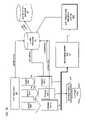
- FIG. 1Cillustrates the integrated network management platform 101 interacting with the maintenance management system 107 for determining alarm correlation with a maintenance event, according to an embodiment of the present invention.
- the platform 101After receiving an alarm from the customer network 103 , the platform 101 attempts to determine whether there is any correlation between the received alarm and an existing maintenance event. It is noted that the correlation can be with multiple maintenance events.
- the platform 101sends alarm information relating to the alarm to the maintenance management system 107 .
- multiple management systems 107e.g., Local Exchange Carriers (LECs), etc.
- LECsLocal Exchange Carriers
- the integrated network management platform 101utilizes a database 108 for storing the maintenance event information from the various maintenance management systems 107 .
- the collection of the maintenance event informationcan be considered part of a subscription process, whereby the information can be retrieved and updated (periodically or only when new information exists).
- the data retrieval processcan be performed as a batched process.
- the retrieved maintenance event informationare stored in the database 108 .
- FIG. 1Cillustrates a view processor utilized in the fault handling module 155 b to provide accurate reporting of alarms, according to one embodiment of the present invention.
- the system 100can provide real-time presentation of fault alarms as well as the storage and reporting of these fault alarms. Such reporting can occur at any time in the present or future. Meaningful reporting is crucial to ensure network reliability and customer satisfaction. This is particularly important in a large network management system, which can produce an inordinate amount of data. This influx of data can overload the reporting system (e.g., maintenance and reporting system 157 b ) with redundant and uncorrelated information, thereby lessening the usefulness of the reporting system.
- reliable global network management systemsare often built with redundancy and diversity in mind for high reliability and availability. This need for redundancy further emphasizes the need for effective processing of data, as redundancy systems can introduce more data relative to a single platform.
- Redundant network management systemsgenerally offer at least two completely diverse means to monitor network faults. If a primary feed for a given network partition is interrupted or becomes degraded, a secondary feed for that same network partition is then utilized for network management operations. During the transition between monitoring via the primary feed to monitoring the secondary feed, the users of the network management system will often experience disruption in their views, as the secondary system is brought online. This transition can occur even if the secondary system is fully operational prior to the switch over. The user's view into the secondary system needs to be established and fully loaded before normal management operations may continue.
- the transitionalso impacts the network management reporting application, which is a consumer of the data. Consequently, the reporting system needs to make adjustments as a result of the transition to the secondary system, often resulting in ‘glitches’ or ‘hiccups’ in the view being presented. Because the secondary feed can contain a completely diverse view, it usually presents slightly different data when compared to the primary feed.
- the most prominent difference between the alarms from the primary and secondary alarm feedsis the identifying portion of the alarm—i.e., that attribute on the fault alarm that uniquely identifies that one and only alarm.
- This identifying attributecan be denoted as an “alarm ID,” which can be produced internally by the Fault Analysis and Elimination Tier 153 .
- the primary fault analysis and secondary fault analysis platforms(not shown) are unique and distinct, the alarm ID that is reported for an alarm will be different from that of the corresponding alarm ID on the sibling fault analysis platform. It is this alarm ID that is fed to the reporting system for report generation.
- the abrupt and unplanned switch between the primary and secondary fault analysis platformcauses a nearly identical stream of fault alarms to be stored and updated into the reporting database. However, all the alarm IDs for these alarms are now different simply because they have been originated from a distinct and separate secondary fault analysis platform.
- the reporting system(e.g., system 157 b ) has to correlate alarms from both the primary and secondary fault analysis platforms, depending on the type of report being generated. In many cases, there will be two copies of every alarm in a given report—i.e., one from the primary fault platform, and another from the secondary fault platform. This duplication causes confusion for the user and can distort, for instance, metrics reporting or Mean-Time to Repair reporting. The redundancy of data also leads to much higher storage requirements, which in itself can lead to reduced performance on the reporting platform.
- the system 100employs a fault handling module 155 b that includes a view processor 161 for converging distinctly separate fault management views into a single view, and stores this unified view into a database of the reporting system 157 b .
- the view processor 161provides a single view that represents two or more distinctly different alarm streams from one or more fault analysis platforms is disclosed.
- the view processor 161can examine one or more attributes of a fault alarm, all of which must match in order for the view processor 161 to recognize identical alarms originating from either the primary or secondary fault analysis platforms.
- the attributes used for this identificationcan be different for each type of fault analysis platform (e.g., whether the platform is a switch management platform, a Synchronous Optical Network (SONET) transport management platform, an IP Management platform, etc.).
- SONETSynchronous Optical Network
- alarms and/or eventsare generated by the customer network 103 , and forwarded via either the primary alarm feed, the secondary alarm feed, or both to the view processor 161 that resides within the Fault Processing Tier 155 .
- the primary alarm feedcan include those alarms captured by the primary fault analysis platform, while the secondary alarm feed provide alarms captured by the secondary fault analysis platform.
- the alarm attributes used to determine the merge criteriaare extracted from the alarm. These alarm attributes constitute a “merge key”. This merge key can be different, depending on the originating system residing on the Fault Analysis and Elimination Tier 153 . For any given originating system however, the merge key is guaranteed to be identical for both the primary and secondary alarm feeds.
- the view processor 161then converts this to a hash value, and searches an in-memory cache (not shown), which contains all of the hashed merge keys that the view processor 161 is managing.
- the view processor 161marks the incoming alarm as a match for an existing alarm, converts the merge key to a ‘child’ key, and compares all alarm attributes to the existing alarm that the previously located merge key identifies. If any attributes are found to be different, the view processor 161 produces an alarm update record, and stores this record in an alarm database 163 . The view processor 161 then sends this alarm update record in, for example, XML format to the Repair Management Tier 157 .
- the view processor 161marks the incoming alarm as a new alarm and stores the hash value in an alarm key cache (not shown) of the view processor 161 .
- the view processor 161then produces a new alarm record, and stores this record in the alarm database 163 .
- the view processor 161sends this alarm record in XML format to the Repair Management Tier 157 .
- the Customer Portal 157 fis a Web-based application that displays a select list of alarms associated to each signed in customer. Each customer is given access to all fault alarms that are reported on that customer's managed network 103 .
- the alarm records presentedrepresent a single record for each alarm regardless of whether the primary or secondary fault analysis platform captured the alarm. This single record is a product of the merging done by the view processor 161 .
- the alarm database 163in an exemplary embodiment, is a relational database that contains all fault alarms that have been correlated by the view processor 161 .
- the view processor 161produces alarms that have been merged into a single view, regardless of the availability or health of either the primary or secondary fault analysis platform.
- the alarm database 163also contains the relationship between each of the Fault Alarms and the one or more ‘Views’ that that the alarm may have been presented in.
- An alarm history database 165is a long term storage of all alarms and AOR mappings (which is more fully described with respect to FIG. 1D ) stored in the alarm database 163 . As network fault alarms are cleared and closed, they are no longer used by the Repair Management Tier 157 or the view processor 161 , but they still maintained for historical reporting purposes. After each alarm has been closed for no less than three full days, it is moved to the alarm history database 165 , and subsequently deleted from the alarm database 163 . This allows the alarm database 163 to maintain a higher level of performance, since the data includes only those alarms that have not yet closed of have been closed less than some predetermined period (e.g., three days). Thus, the alarm history database 165 is used only for historical reporting, and keeps all alarms and AOR mapping records for a longer duration than the alarm database 163 (e.g., at least 30 full days).
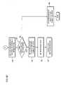
- FIGS. 1D and 1Eshow a view processor capable of mapping areas of responsibility (AOR) alarms into merged alarms, according to one embodiment of the present invention.
- AORmapping areas of responsibility
- FIG. 1Cafter the network faults have been merged by the view processor 161 , the merged alarms/events are stored into the alarm database 163 (step 171 ).
- the Fault Processing Tierthen sends these merged alarms to one or more dynamic views, which are called “Dynamic Areas of Responsibility”, or DAOR, as in step 173 .
- Each DAORis a filtered view that takes as input one or more merged alarm streams from the view processor 161 , and applies a filter that includes one or more alarm attributes (step 175 ). As each alarm matches a filter, an AOR mapping record is created, the enter time is marked, and stored in the alarm database 163 (steps 177 - 179 ).
- AOR Mapping recordin an exemplary embodiment, is a “Date & Time” field, indicating when the alarm first was routed to this filtered view. Any alarm can be routed to the inputs of any DAOR processor; if the alarm matches the specific filter criteria for any DAOR processor, a new AOR Mapping record is created and stored in the alarm database.
- DAOR processesare dynamic in nature due to the filter that defines their respective view.
- a filtercan change at any time by a Network Operations Engineer, a Fault Processing rule change, or a provisioning system.
- the DAORreceives a filter changed message. Once the filter for a DAOR has been changed, the DAOR initiates a full rescan of all inputs it is configured to process, in order to check whether all alarms still match the newly changed filter (as determined in step 183 ). If a particular alarm no longer matches the changed filter, the DAOR updates the AOR Mapping Record for that alarm with a Date & Time field, indicating when the alarm was removed from this filtered view (step 187 ). In step 189 , the alarm can be sent to the connected clients.
- the association between alarms and DAORsis more than a simple one-to-many relationship; it is comprised of those relationships on a timeline and does so in an efficient manner to reduce storage requirements and allow for quicker data retrieval within the reporting system 157 b .
- This detailed recordkeeping within the alarm database 163allows the Maintenance and Reporting System 157 b to maintain accurate historical data for all DAOR views.
- the dynamic nature of fault alarms, filtered fault alarm views, and Surveillance Engineer dutiesrequire the reporting system 157 b to record the entire lifecycle of a given fault alarm, including the various views that the alarm may have entered or exited from. This reporting also requires that the existence or absence of these alarms on either the primary or the secondary fault analysis platforms not interfere with the reporting accuracy.
- the reporting databaseis relieved from the burden of determining whether DAORs have been artificially skewed by a problem on either the primary or secondary fault analysis system.
- the storage of merged alarmsprovides a smoothed and more consistent data set and allows the reporting platform to more accurately assess customer impacts, surveillance engineer productivity, and true Service Level Agreement (SLA) compliance.
- SLAService Level Agreement
- the fault isolation processis next described without regard to any particular type of alarm or causes of network failure or disruption in operation. It is recognized that the automation process can be readily adapted to accommodate any type of alarms and causes. Also, although the steps of the processes of FIGS. 2-7 are described in a sequential and ordered fashion, it is contemplated various steps can be performed concurrently, or otherwise executed out of the described sequence.
- FIG. 2Ais a flowchart of a fault isolation process performed as a managed service, according to an embodiment of the present invention.
- the customer network 103is monitored by the service provider as a managed service, thereby eliminating the customer organization from the cost and burden of performing its own network monitoring and recovery.
- the real-time management and analysis module 153 awithin the fault analysis and elimination tier 153 .
- the real-time management and analysis module 153 aUpon receiving alarms from the customer network 103 , the real-time management and analysis module 153 a performs a root cause determination, per steps 203 and 205 . This module 153 a can correlate multiple alarm reports to a single cause.
- an alarm specific to this causeis communicated to the fault handling module 155 b for automated fault handling (step 207 ).
- the fault processing tier 155gathers data via the topology services module 155 a from topology sources and determines whether the alarm is associated with a maintenance event using the fault handling module 155 b . If the alarm is occurring within a maintenance window, the alarm is updated with the maintenance information and subsequently used by the automation engine 155 d . It is noted that in a redundant system (as described in FIGS. 1C-1E ), the above process occurs within each of the primary fault analysis platform and the secondary fault analysis platform, in which the resultant alarms can be merged by the view processor 161 .
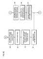
- FIG. 2Bshows a process for correlating an alarm with a maintenance event, according to an embodiment of the present invention.
- the workflow engine 155 egenerates one or more workflow events corresponding to the alarm received from the customer network 103 .
- the integrated network management platform 101consults with one or more maintenance management systems 107 through a subscription process to collect maintenance event information (which are subsequently stored in the database 108 )—i.e., corresponding to outstanding maintenance events 1 through event N—utilizing a database query, for example.
- the collected informationare then stored, as in step 223 , in a local database 108 .
- the platform 101retrieves the maintenance event information (which were previously downloaded from the maintenance management systems 107 ) from the database 108 , per step 225 .
- the automation engine 155 dcan differentiate the automated handling of the alarm based on the maintenance ticket ID, as in step 227 .
- the automation engine 155 dinitiates generation of an appropriate trouble ticket by the trouble management system 157 d .
- the automation engine 155 dpolls the pertinent maintenance management system 107 to determine status of the maintenance activity (e.g., whether it is complete). It is also contemplated that the alarm can be correlated with multiple events across different systems 107 ; in this instance, the automated process polls all such systems 107 .
- the automation engine 155 dchecks whether the subject alarm is clear.
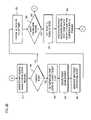
- FIGS. 3A-3Eare a flowchart of an automation process for fault handling, according to one embodiment of the present invention.
- the automation processbegins when the alarms from the real-time management and analysis module 153 a are passed to the automation engine 155 d , per step 301 .
- a workflow eventis created for a new customer outage alarm. Events are used to keep track of alarm status within the platform 101 , and to serve as a container for holding one or more alarms related to a single network event.
- the eventcan be viewed via a workflow GUI (e.g., supported by the surveillance and operation system 157 a ), thereby providing status on the automated alarm handling process, as in step 305 .
- a workflow GUIe.g., supported by the surveillance and operation system 157 a
- the real-time management and analysis module 153 ahas the ability to send both the parent root cause alarm and the sympatheic children alarms.
- the child alarmsare not automated; however, if a child alarm is received, the automation engine 155 d will attempt to associate that child alarm with the parent's and to add the child alarm to the event.
- the automation engine 155 dadds the alarm to the created workflow event.
- the Ticket Owning Group/Ticket Managing Group(TOG/TMG) is set for the ticket to be created.
- the TOGrepresents an operations group that is responsible for the ticket; this typically is the group that created the ticket.
- the TMGis the operations group that currently responsible for working the ticket.
- the TOG and/or the TMGcan be set specific to a NOC group and obtained from information provided by the services portal 153 b .
- the TOG and TMGcan both be set based on the NOC group.
- the workflow event stateis set to a Timed (TMD) Wait/Get Data state; this information can be accessed via the workflow GUI (step 311 ).
- TMDTimed
- step 313the process “waits” for a configurable period (e.g., 5 minutes) to ensure that the alarm stays active in the network before a ticket and other troubleshooting activities commence.
- the trouble management system 157 dcan be consulted to determine whether an existing ticket for the same customer circuit and IP address is already in the ticketing system 157 d . If an existing ticket is found, the ticket number is recorded; this information can be used during the ticketing phase of the automation.
- the services portal databaseis queried to obtain customer specific information associated with the alarm from the real-time management and analysis system 153 a.
- the configurable periodcan be set for the duration of the longest running task. According to an embodiment of the present invention, this period can be set based on the alarm type. At the end of the configurable period, the state of the workflow event and the alarm is checked as follows.
- the processdetermines whether the alarm is clear, as in step 315 . If the alarm is clear, the workflow event is closed (step 317 ), and the automation process ends. However, if the alarm is not clear, the event is checked to determine whether it has been manually closed (step 319 ). If the event has been closed, it is likely that the analyst does not want to continue with the automated handling of the alarm.
- the processUpon determining that the event is not closed, the process examines whether the event is manually associated with a trouble ticket, per step 321 . If the event has had a ticket associated with it, then the analyst has taken the necessary action to resolve the issues. Hence, the automation process ceases. If the workflow event is not associated with a trouble ticket, the TOG/TMG is set for the ticket that will be created (step 323 ).
- the automationproceeds to the next step, as shown in FIG. 3C .
- the processexamines, as in step 325 , whether the alarm has a maintenance indicator, which specifies that the alarm is associated with a maintenance activity set by the surveillance and operations system 157 a or the services portal 153 b . If the indicator is set, then the workflow event is set to a maintenance ticketing state, per step 327 .
- a trouble ticket for the alarmis open, per step 329 .
- the trouble ticketcan be opened with both the TMG and TOG set to the NOC group, for example.
- the processthen waits for a predetermined duration (e.g., 5 minutes) to allow for system updates.
- a predetermined duratione.g., 5 minutes
- the processchecks whether the maintenance activity has ended, and sets the workflow event state to “maintenance check.”
- the processthen re-queries the services portal 153 b and surveillance and operations system 157 a to determine if the alarm is still within the maintenance window. If so, this is monitored until the alarm exits from the maintenance activity; maintenance is over at this point.
- the ticketis closed after the maintenance activity is completed. The ticket number is recorded.
- the processchecks whether the alarm is still active, per step 335 . If the alarm is still active, the TMG and TOG parameters are re-set based on the original rules (step 337 ). In step 338 , the maintenance ID (identifier) is stored. The process continues in which a new trouble ticket is created, as in step 339 ; the new trouble ticket can be associated with the stored maintenance ID, such that this ID can be “pasted” into the newly created ticket. If the alarm is not active, the event is closed, per step 341 , and the automation process terminates.
- step 339the automation proceeds to the step of creating a new trouble ticket.
- trouble ticketing creation processis described with respect to interface ticketing and circuit ticketing; however, it is contemplated that any type of trouble ticket can be supported depending on the configuration and requirements of the customer networks 103 .
- a new trouble ticketis generated based on information (or instructions) from the network operations center (NOC), per step 343 .
- NOCnetwork operations center
- the event stateis set to “interface ticketing,” and an interface ticket is created. It is determined, as in step 345 , whether a ticket is in existence. If a trouble ticket does exist, then the workflow event state is set to an “Update ticket” state (step 347 ). Next, the ticket can be updated with alarm information, as necessary (step 349 ).
- This newly created interface ticketis then associated with the existing trouble ticket (step 351 ).
- the workflow eventis accordingly set to “circuit ticketing.”
- the circuit ticketis created. Comments can be further associated with the ticket, particularly the circuit ticket, by setting the event to a “Ticket comments” state. The comments by a network analyst, for example, can be added to the trouble ticket—e.g., responses from the services portal 153 b can be recorded on a ticket activity log of the subject ticket. This new circuit ticket is then associated with the existing trouble ticket.
- new ticketscan be generated as described above based on information (or instructions) from the NOC; however, because no ticket is associated with the alarm, updating is not necessary. It is noted that if this alarm was originally in a maintenance state (and as a result of the maintenance activity completing and the alarm is now going through the normal process), the new ticket will be updated with the ticket ID of the maintenance ticket that was created earlier. For example, if an interface ticket or a circuit ticket is required, the event state is respectively set to “interface ticketing” or “circuit ticketing” and the ticket is created. Comments can be further provided by the network analyst, as appropriate.
- the automation processsends notifications to the customer organization about the tickets.
- notificationsinvolve parsing out a list of all users to be notified, as well as the methodology (e.g., email, page, voice, etc.) for receiving these notifications. Additionally, these notifications can be based on the roles of these users. For instance, a contact with supervisory role can be notified of more severe alarms as part of an escalation process.
- step 355it is determined whether the alarm is of a type that requires testing. If the alarm type is not one of the specifically supported alarms that require testing, the process performs a monitor service, as more fully described below.
- the ticketis set to a “working” state to indicate that the automation process is handling the ticket (step 357 ).
- the device associated with the root cause alarmis accessed, as in step 359 .
- the processissues data retrieval commands, via the command factory 155 c , to gather data on the problem.
- the ticketis referred to the testing system 157 c , per step 361 .
- the processdetermines, as in step 363 , whether the NOC is the responsible entity. If so, the automation process again accesses the device associated with the root cause alarm and issues the necessary data retrieval commands to obtain status data after the testing system 157 c has performed testing to resolve the problem (step 365 ). Alternatively, these commands can be issued before testing, depending on the requirements of the NOC.
- step 367the process provides post testing notifications to the users. At this stage, the ticket is unassigned, and the process proceeds to perform the monitoring service (steps 369 and 371 ).
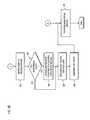
- FIG. 4is a flowchart of a notification process, according to an embodiment of the present invention.
- the notification processbegins with obtaining the customer contact information and any notification criteria that the customer has specified regarding who, how, and when notifications are to be supplied (step 401 ). Assuming the customer notification feature is enabled for a user and the alarm is of a type that affects network services, these notifications are supplied via voice, email or pager, according to one embodiment of the present invention. If voice notification is requested as determined in step 403 , the alarm is set to indicate voice notification (as in step 405 ).
- the trouble ticket activityis configured for email notification with all email addresses designated for notification. Likewise, if pager notification is desired, the trouble ticket activity is set for pager notification with all pager numbers designated for notification (steps 411 and 413 ).
- the automation processis capable of waiting for a response or instructions from the contact for a certain configurable duration. For instance, with pager notification, the user receives notification text, and provides a text response to the workflow engine 155 e , which then acts appropriately to resolve the alarm.
- FIG. 5is a flowchart of a data collection process, according to one embodiment of the present invention.
- the alarm typeis determined, and the workflow event state is set based on this determined type (step 503 ).
- a command associated with the alarm typeis issued by the command factory 155 c and is executed, as in step 505 .
- the result of the commandis recorded to a ticket activity log, per step 507 .
- the event stateis set to “Issuing CF commands for Router Down.” It is contemplated that various alarm types can be utilized, including “Interface down” to indicate that an interface of a network component has failed, and “IP down” to indicate a problem with the IP addressing, for example.
- FIGS. 6A-6Dare a flowchart of a process for fault testing, according to an embodiment of the present invention.
- the fault testing processbegins with examining the test flag, as in step 601 , and determining whether the flag is set to indicate that no testing is required (step 603 ). If the flag is set to false, then the ticket is updated to indicate “no testing,” per step 605 . Work on the ticket is ceased, as in step 607 . This alerts the NOC that the automation process is no longer working on the ticket. In step 609 , the process continues to monitor the ticket (step 609 ).
- step 603if the ticket is not set to false, then the automation process determines whether the alarm type is of a pre-specified type, per step 611 .
- step 613the process checks whether the services portal 153 b has a response to the alarm.
- step 614the process determines whether the testing has been approved by the customer.
- the customercan pre-authorize certain testing; however, if the testing is unusual (as defined and specified by the customer) or can significantly impact the customer's operations, then testing is likely to require approval beyond the pre-authorized testing scenarios.
- the ticketis updated accordingly.
- the alarm typeis Interface Logical Connection Down or IP Down
- the automation processchecks for the connection identifier (e.g., Data Link Connection Identifier (DLCI)) in the response from the services portal 153 b .
- the eventcan thus be updated to indicate that no DLCI is provided. Thereafter, the process returns to the monitoring step 609 .
- DLCIData Link Connection Identifier
- a working group of the testing system 157 cis set (step 617 ).
- the workflow event stateas in step 619 , is set to “Refer to Testing System.”
- the automation processaccordingly refers the ticket to the testing system 157 c for handling, per step 621 (shown in FIG. 6B ), and waits for a configurable duration for the system 157 c to accept the ticket. If the ticket is not accepted (as determined in step 623 ), the alarm is updated to indicated non-acceptance of the ticket, as in step 625 .
- the automation processthen retrieves the ticket back for handling, per step 627 . At this point, the process proceeds, as in step 629 , to perform post testing notifications. This notification process is similar to that of FIG. 4 , with information relating to testing being provided.
- the workflow eventis set to a “Testing” state.
- the automation processdetermines whether the alarm is still active, as in step 633 . If the alarm is not active, the workflow event state is set to “All Alarms Clear” state (step 635 ). The ticket is taken back, per step 637 , by the automation process from the testing system 157 c . Thereafter, both the ticket and the event activity are updated to indicate that the alarm was cleared during testing, as in step 639 . In step 641 , the post testing notification is performed.
- end-to-end diagnosticsare performed based on the identified alarm, such as an alarm circuit (step 643 ).
- This testingcan determine whether the problem is internal to the customer network 103 , within a third party provider (not shown) or the service provider network.
- the ticketis referred to an appropriate entity based on the diagnosis to repair or otherwise remedy the problem.
- notificationis provided to indicate completion of the test (step 647 ).
- the automation engine 155 dcan wait, as in step 649 , for a configurable period of time (e.g., up to 60 minutes for the testing system 157 c to complete the test), as set by a timer, for example. If the timer expires and the test is not completed (as determined in step 651 ), the workflow event state is set to “Test Not Completed,” as in step 653 . The process retrieves the ticket from the testing system 157 c , as in step 655 . In step 657 , the automation engine 155 d performs post testing notification. In step 659 , the workflow event state is set to “Test Completed.”
- a configurable period of timee.g., up to 60 minutes for the testing system 157 c to complete the test
- FIG. 7is a flowchart of a process for network monitoring, according to an embodiment of the present invention.
- the workflow event stateis set to “Monitor Service” (step 701 ).
- the ticketis then monitored, per step 703 .
- This monitoringcan be executed on a periodic basis (e.g., every 2 minutes), until the status of the ticket is either resolved, void, or closed, as determined in step 705 .
- a timer for the monitoring processis initialized; the value of this monitor timer can be set based on historical data relating to the duration of the associated activities (e.g., 4 hours) for resolving the ticket.
- step 709the alarm status is monitored. Thereafter, it is determined whether the alarm transitioned from a “Clear” state to an “Unclear” state (step 711 ). If the ticket is undergoing the monitor service and the alarm moves from the Clear state to the Unclear state, then the ticket is placed back into the “Open to be Worked” state, as in step 713 . Next, the ticket activity log is updated, as in step 715 , accordingly to indicate that the ticket is now being worked on.
- the processcan access the services portal 153 b , per step 717 , to obtain the customer contacts (in case the contacts have changed) for sending out notifications.
- notificationscan be based on any number of triggers—e.g., time, events, rules, etc.
- the customer contactcan be notified if the ticket is a “high” priority (or whatever priority setting specified by the customer).
- the notification processcan follow that of FIG. 4 .
- the processdetermines whether the monitor timer has expired, per step 719 . If the timer has not lapsed, the monitoring process continues (returns to step 709 ).
- FIG. 8illustrates a computer system 800 upon which an embodiment according to the present invention can be implemented.
- the computer system 800includes a bus 801 or other communication mechanism for communicating information and a processor 803 coupled to the bus 801 for processing information.
- the computer system 800also includes main memory 805 , such as a random access memory (RAM) or other dynamic storage device, coupled to the bus 801 for storing information and instructions to be executed by the processor 803 .
- Main memory 805can also be used for storing temporary variables or other intermediate information during execution of instructions by the processor 803 .
- the computer system 800may further include a read only memory (ROM) 807 or other static storage device coupled to the bus 801 for storing static information and instructions for the processor 803 .
- ROMread only memory
- a storage device 809such as a magnetic disk or optical disk, is coupled to the bus 801 for persistently storing information and instructions.
- the computer system 800may be coupled via the bus 801 to a display 811 , such as a cathode ray tube (CRT), liquid crystal display, active matrix display, or plasma display, for displaying information to a computer user.
- a display 811such as a cathode ray tube (CRT), liquid crystal display, active matrix display, or plasma display
- An input device 813is coupled to the bus 801 for communicating information and command selections to the processor 803 .
- a cursor control 815is Another type of user input device, such as a mouse, a trackball, or cursor direction keys, for communicating direction information and command selections to the processor 803 and for controlling cursor movement on the display 811 .
- the processes described hereinare performed by the computer system 800 , in response to the processor 803 executing an arrangement of instructions contained in main memory 805 .
- Such instructionscan be read into main memory 805 from another computer-readable medium, such as the storage device 809 .
- Execution of the arrangement of instructions contained in main memory 805causes the processor 803 to perform the process steps described herein.
- processors in a multi-processing arrangementmay also be employed to execute the instructions contained in main memory 805 .
- hard-wired circuitrymay be used in place of or in combination with software instructions to implement the embodiment of the present invention.
- embodiments of the present inventionare not limited to any specific combination of hardware circuitry and software.
- the computer system 800also includes a communication interface 817 coupled to bus 801 .
- the communication interface 817provides a two-way data communication coupling to a network link 819 connected to a local network 821 .
- the communication interface 817may be a digital subscriber line (DSL) card or modem, an integrated services digital network (ISDN) card, a cable modem, a telephone modem, or any other communication interface to provide a data communication connection to a corresponding type of communication line.
- communication interface 817may be a local area network (LAN) card (e.g. for EthernetTM or an Asynchronous Transfer Model (ATM) network) to provide a data communication connection to a compatible LAN.
- LANlocal area network
- Wireless linkscan also be implemented.
- communication interface 817sends and receives electrical, electromagnetic, or optical signals that carry digital data streams representing various types of information.
- the communication interface 817can include peripheral interface devices, such as a Universal Serial Bus (USB) interface, a PCMCIA (Personal Computer Memory Card International Association) interface, etc.
- USBUniversal Serial Bus
- PCMCIAPersonal Computer Memory Card International Association
- the network link 819typically provides data communication through one or more networks to other data devices.
- the network link 819may provide a connection through local network 821 to a host computer 823 , which has connectivity to a network 825 (e.g. a wide area network (WAN) or the global packet data communications network now commonly referred to as the “Internet”) or to data equipment operated by a service provider.
- the local network 821 and the network 825both use electrical, electromagnetic, or optical signals to convey information and instructions.
- the signals through the various networks and the signals on the network link 819 and through the communication interface 817 , which communicate digital data with the computer system 800are exemplary forms of carrier waves bearing the information and instructions.
- the computer system 800can send messages and receive data, including program code, through the network(s), the network link 819 , and the communication interface 817 .
- a server(not shown) might transmit requested code belonging to an application program for implementing an embodiment of the present invention through the network 825 , the local network 821 and the communication interface 817 .
- the processor 803may execute the transmitted code while being received and/or store the code in the storage device 809 , or other non-volatile storage for later execution. In this manner, the computer system 800 may obtain application code in the form of a carrier wave.
- Non-volatile mediainclude, for example, optical or magnetic disks, such as the storage device 809 .
- Volatile mediainclude dynamic memory, such as main memory 805 .
- Transmission mediainclude coaxial cables, copper wire and fiber optics, including the wires that comprise the bus 801 . Transmission media can also take the form of acoustic, optical, or electromagnetic waves, such as those generated during radio frequency (RF) and infrared (IR) data communications.
- RFradio frequency
- IRinfrared
- Computer-readable mediainclude, for example, a floppy disk, a flexible disk, hard disk, magnetic tape, any other magnetic medium, a CD-ROM, CDRW, DVD, any other optical medium, punch cards, paper tape, optical mark sheets, any other physical medium with patterns of holes or other optically recognizable indicia, a RAM, a PROM, and EPROM, a FLASH-EPROM, any other memory chip or cartridge, a carrier wave, or any other medium from which a computer can read.
- a floppy diska flexible disk, hard disk, magnetic tape, any other magnetic medium, a CD-ROM, CDRW, DVD, any other optical medium, punch cards, paper tape, optical mark sheets, any other physical medium with patterns of holes or other optically recognizable indicia, a RAM, a PROM, and EPROM, a FLASH-EPROM, any other memory chip or cartridge, a carrier wave, or any other medium from which a computer can read.
- the instructions for carrying out at least part of the present inventionmay initially be borne on a magnetic disk of a remote computer.
- the remote computerloads the instructions into main memory and sends the instructions over a telephone line using a modem.
- a modem of a local computer systemreceives the data on the telephone line and uses an infrared transmitter to convert the data to an infrared signal and transmit the infrared signal to a portable computing device, such as a personal digital assistant (PDA) or a laptop.
- PDApersonal digital assistant
- An infrared detector on the portable computing devicereceives the information and instructions borne by the infrared signal and places the data on a bus.
- the busconveys the data to main memory, from which a processor retrieves and executes the instructions.
- the instructions received by main memorycan optionally be stored on storage device either before or after execution by processor.
Landscapes
- Engineering & Computer Science (AREA)
- Signal Processing (AREA)
- Computer Networks & Wireless Communication (AREA)
- Data Exchanges In Wide-Area Networks (AREA)
Abstract
Description
- AOR Area Of Responsibility
- API Application Programming Interface
- ATM Asynchronous Transfer Mode
- CD-ROM Compact Disc-Read Only Memory
- CDRW Compact Disc Read-Writable
- CORBA Common Object Request Broker Architecture
- CP Customer Portal
- CPE Customer Premises Equipment
- DAOR Dynamic Area Of Responsibility
- DIY Do-It-Yourself
- DLCI Data Link Connection Identifier
- DSP Digital Signaling Processing
- DVD Digital Versatile Disc (formerly Digital Video Disc)
- EPROM Electrically Programmable Read-Only Memory
- ESP Enterprise Services Portal
- GUI Graphical User Interface
- IP Internet Protocol
- IR Infrared
- ID Identifier
- IP Internet Protocol
- J2EE JAVA® 2 Enterprise Edition
- LAN Local Area Network
- LEC Local Exchange Carrier
- NOC Network Operations Control
- ORB Object Request Broker
- PCMCIA Personal Computer Memory Card International Association
- PDA Personal Digital Assistant
- PROM Programmable Read-Only Memory
- PSTN Public Switched Telephone Network
- RAM Random Access Memory
- RF Radio Frequency
- SLA Service Level Agreement
- TMG Ticket Managing Group
- TOG Ticket Owning Group
- USB Universal Serial Bus
- WAN Wide Area Network
- XML extensible Mark-up Language
Claims (17)
Priority Applications (1)
| Application Number | Priority Date | Filing Date | Title |
|---|---|---|---|
| US11/404,503US7525422B2 (en) | 2005-04-14 | 2006-04-14 | Method and system for providing alarm reporting in a managed network services environment |
Applications Claiming Priority (2)
| Application Number | Priority Date | Filing Date | Title |
|---|---|---|---|
| US67189905P | 2005-04-14 | 2005-04-14 | |
| US11/404,503US7525422B2 (en) | 2005-04-14 | 2006-04-14 | Method and system for providing alarm reporting in a managed network services environment |
Publications (2)
| Publication Number | Publication Date |
|---|---|
| US20060244585A1 US20060244585A1 (en) | 2006-11-02 |
| US7525422B2true US7525422B2 (en) | 2009-04-28 |
Family
ID=37233921
Family Applications (1)
| Application Number | Title | Priority Date | Filing Date |
|---|---|---|---|
| US11/404,503Expired - Fee RelatedUS7525422B2 (en) | 2005-04-14 | 2006-04-14 | Method and system for providing alarm reporting in a managed network services environment |
Country Status (1)
| Country | Link |
|---|---|
| US (1) | US7525422B2 (en) |
Cited By (117)
| Publication number | Priority date | Publication date | Assignee | Title |
|---|---|---|---|---|
| US20060235558A1 (en)* | 2002-08-28 | 2006-10-19 | Tokyo Eectron Limited | Method of scavenging intermediate formed by reaction of oxidoreductase with substrate |
| US20100014651A1 (en)* | 2008-07-17 | 2010-01-21 | Paritosh Bajpay | Method and apparatus for processing of a toll free call service alarm |
| US20100042571A1 (en)* | 2007-08-08 | 2010-02-18 | Anthony Scott Dobbins | Methods, Systems, and Computer-Readable Media for Facility Integrity Testing |
| US20110141914A1 (en)* | 2009-12-15 | 2011-06-16 | Chen-Yui Yang | Systems and Methods for Providing Ethernet Service Circuit Management |
| US20130145300A1 (en)* | 2011-12-02 | 2013-06-06 | Verizon Patent And Licensing Inc. | Workflow-Based Delivery Management Methods and Systems |
| US8713467B1 (en)* | 2013-08-09 | 2014-04-29 | Palantir Technologies, Inc. | Context-sensitive views |
| US8799799B1 (en) | 2013-05-07 | 2014-08-05 | Palantir Technologies Inc. | Interactive geospatial map |
| US8812960B1 (en) | 2013-10-07 | 2014-08-19 | Palantir Technologies Inc. | Cohort-based presentation of user interaction data |
| US8832594B1 (en) | 2013-11-04 | 2014-09-09 | Palantir Technologies Inc. | Space-optimized display of multi-column tables with selective text truncation based on a combined text width |
| US8855999B1 (en) | 2013-03-15 | 2014-10-07 | Palantir Technologies Inc. | Method and system for generating a parser and parsing complex data |
| US8868486B2 (en) | 2013-03-15 | 2014-10-21 | Palantir Technologies Inc. | Time-sensitive cube |
| US8890676B1 (en)* | 2011-07-20 | 2014-11-18 | Google Inc. | Alert management |
| US8917274B2 (en) | 2013-03-15 | 2014-12-23 | Palantir Technologies Inc. | Event matrix based on integrated data |
| US8924872B1 (en) | 2013-10-18 | 2014-12-30 | Palantir Technologies Inc. | Overview user interface of emergency call data of a law enforcement agency |
| US8930897B2 (en) | 2013-03-15 | 2015-01-06 | Palantir Technologies Inc. | Data integration tool |
| US8937619B2 (en) | 2013-03-15 | 2015-01-20 | Palantir Technologies Inc. | Generating an object time series from data objects |
| US8938686B1 (en) | 2013-10-03 | 2015-01-20 | Palantir Technologies Inc. | Systems and methods for analyzing performance of an entity |
| US20150097664A1 (en)* | 2013-10-03 | 2015-04-09 | Tyco Safety Products Canada Ltd. | Method and apparatus for determining maintenance needs and validating the installation of an alarm system |
| US9009171B1 (en) | 2014-05-02 | 2015-04-14 | Palantir Technologies Inc. | Systems and methods for active column filtering |
| US9009827B1 (en) | 2014-02-20 | 2015-04-14 | Palantir Technologies Inc. | Security sharing system |
| US9021384B1 (en) | 2013-11-04 | 2015-04-28 | Palantir Technologies Inc. | Interactive vehicle information map |
| US9021260B1 (en) | 2014-07-03 | 2015-04-28 | Palantir Technologies Inc. | Malware data item analysis |
| US9043894B1 (en) | 2014-11-06 | 2015-05-26 | Palantir Technologies Inc. | Malicious software detection in a computing system |
| US9043696B1 (en) | 2014-01-03 | 2015-05-26 | Palantir Technologies Inc. | Systems and methods for visual definition of data associations |
| US9116975B2 (en) | 2013-10-18 | 2015-08-25 | Palantir Technologies Inc. | Systems and user interfaces for dynamic and interactive simultaneous querying of multiple data stores |
| US9118544B2 (en) | 2008-07-17 | 2015-08-25 | At&T Intellectual Property I, L.P. | Method and apparatus for providing automated processing of a switched voice service alarm |
| US9123086B1 (en) | 2013-01-31 | 2015-09-01 | Palantir Technologies, Inc. | Automatically generating event objects from images |
| US9202249B1 (en) | 2014-07-03 | 2015-12-01 | Palantir Technologies Inc. | Data item clustering and analysis |
| US9223773B2 (en) | 2013-08-08 | 2015-12-29 | Palatir Technologies Inc. | Template system for custom document generation |
| US9256664B2 (en) | 2014-07-03 | 2016-02-09 | Palantir Technologies Inc. | System and method for news events detection and visualization |
| US9335897B2 (en) | 2013-08-08 | 2016-05-10 | Palantir Technologies Inc. | Long click display of a context menu |
| US9335911B1 (en) | 2014-12-29 | 2016-05-10 | Palantir Technologies Inc. | Interactive user interface for dynamic data analysis exploration and query processing |
| US9367872B1 (en) | 2014-12-22 | 2016-06-14 | Palantir Technologies Inc. | Systems and user interfaces for dynamic and interactive investigation of bad actor behavior based on automatic clustering of related data in various data structures |
| US9383911B2 (en) | 2008-09-15 | 2016-07-05 | Palantir Technologies, Inc. | Modal-less interface enhancements |
| US9454281B2 (en) | 2014-09-03 | 2016-09-27 | Palantir Technologies Inc. | System for providing dynamic linked panels in user interface |
| US9454785B1 (en) | 2015-07-30 | 2016-09-27 | Palantir Technologies Inc. | Systems and user interfaces for holistic, data-driven investigation of bad actor behavior based on clustering and scoring of related data |
| US9483162B2 (en) | 2014-02-20 | 2016-11-01 | Palantir Technologies Inc. | Relationship visualizations |
| US9501851B2 (en) | 2014-10-03 | 2016-11-22 | Palantir Technologies Inc. | Time-series analysis system |
| US9552615B2 (en) | 2013-12-20 | 2017-01-24 | Palantir Technologies Inc. | Automated database analysis to detect malfeasance |
| US9619557B2 (en) | 2014-06-30 | 2017-04-11 | Palantir Technologies, Inc. | Systems and methods for key phrase characterization of documents |
| US9727560B2 (en) | 2015-02-25 | 2017-08-08 | Palantir Technologies Inc. | Systems and methods for organizing and identifying documents via hierarchies and dimensions of tags |
| US9727622B2 (en) | 2013-12-16 | 2017-08-08 | Palantir Technologies, Inc. | Methods and systems for analyzing entity performance |
| US9767172B2 (en) | 2014-10-03 | 2017-09-19 | Palantir Technologies Inc. | Data aggregation and analysis system |
| US9785773B2 (en) | 2014-07-03 | 2017-10-10 | Palantir Technologies Inc. | Malware data item analysis |
| US9785328B2 (en) | 2014-10-06 | 2017-10-10 | Palantir Technologies Inc. | Presentation of multivariate data on a graphical user interface of a computing system |
| US9785317B2 (en) | 2013-09-24 | 2017-10-10 | Palantir Technologies Inc. | Presentation and analysis of user interaction data |
| US9817563B1 (en) | 2014-12-29 | 2017-11-14 | Palantir Technologies Inc. | System and method of generating data points from one or more data stores of data items for chart creation and manipulation |
| US9823818B1 (en) | 2015-12-29 | 2017-11-21 | Palantir Technologies Inc. | Systems and interactive user interfaces for automatic generation of temporal representation of data objects |
| US9836580B2 (en) | 2014-03-21 | 2017-12-05 | Palantir Technologies Inc. | Provider portal |
| US9857958B2 (en) | 2014-04-28 | 2018-01-02 | Palantir Technologies Inc. | Systems and user interfaces for dynamic and interactive access of, investigation of, and analysis of data objects stored in one or more databases |
| US9870205B1 (en) | 2014-12-29 | 2018-01-16 | Palantir Technologies Inc. | Storing logical units of program code generated using a dynamic programming notebook user interface |
| US9880987B2 (en) | 2011-08-25 | 2018-01-30 | Palantir Technologies, Inc. | System and method for parameterizing documents for automatic workflow generation |
| US9886467B2 (en) | 2015-03-19 | 2018-02-06 | Plantir Technologies Inc. | System and method for comparing and visualizing data entities and data entity series |
| US9891808B2 (en) | 2015-03-16 | 2018-02-13 | Palantir Technologies Inc. | Interactive user interfaces for location-based data analysis |
| US9898528B2 (en) | 2014-12-22 | 2018-02-20 | Palantir Technologies Inc. | Concept indexing among database of documents using machine learning techniques |
| US9898335B1 (en) | 2012-10-22 | 2018-02-20 | Palantir Technologies Inc. | System and method for batch evaluation programs |
| US9898509B2 (en) | 2015-08-28 | 2018-02-20 | Palantir Technologies Inc. | Malicious activity detection system capable of efficiently processing data accessed from databases and generating alerts for display in interactive user interfaces |
| US9911317B2 (en) | 2013-10-03 | 2018-03-06 | Tyco Safety Products Canada Ltd. | Method and system for determining maintenance needs and validating the installation of an alarm system |
| US9946738B2 (en) | 2014-11-05 | 2018-04-17 | Palantir Technologies, Inc. | Universal data pipeline |
| US9965534B2 (en) | 2015-09-09 | 2018-05-08 | Palantir Technologies, Inc. | Domain-specific language for dataset transformations |
| US9965937B2 (en) | 2013-03-15 | 2018-05-08 | Palantir Technologies Inc. | External malware data item clustering and analysis |
| US9984133B2 (en) | 2014-10-16 | 2018-05-29 | Palantir Technologies Inc. | Schematic and database linking system |
| US9996595B2 (en) | 2015-08-03 | 2018-06-12 | Palantir Technologies, Inc. | Providing full data provenance visualization for versioned datasets |
| US10037383B2 (en) | 2013-11-11 | 2018-07-31 | Palantir Technologies, Inc. | Simple web search |
| US10037314B2 (en) | 2013-03-14 | 2018-07-31 | Palantir Technologies, Inc. | Mobile reports |
| US10102369B2 (en) | 2015-08-19 | 2018-10-16 | Palantir Technologies Inc. | Checkout system executable code monitoring, and user account compromise determination system |
| US10120857B2 (en) | 2013-03-15 | 2018-11-06 | Palantir Technologies Inc. | Method and system for generating a parser and parsing complex data |
| US10180929B1 (en) | 2014-06-30 | 2019-01-15 | Palantir Technologies, Inc. | Systems and methods for identifying key phrase clusters within documents |
| US10180977B2 (en) | 2014-03-18 | 2019-01-15 | Palantir Technologies Inc. | Determining and extracting changed data from a data source |
| US10198515B1 (en) | 2013-12-10 | 2019-02-05 | Palantir Technologies Inc. | System and method for aggregating data from a plurality of data sources |
| US10216801B2 (en) | 2013-03-15 | 2019-02-26 | Palantir Technologies Inc. | Generating data clusters |
| US10229284B2 (en) | 2007-02-21 | 2019-03-12 | Palantir Technologies Inc. | Providing unique views of data based on changes or rules |
| US10230746B2 (en) | 2014-01-03 | 2019-03-12 | Palantir Technologies Inc. | System and method for evaluating network threats and usage |
| US10275778B1 (en) | 2013-03-15 | 2019-04-30 | Palantir Technologies Inc. | Systems and user interfaces for dynamic and interactive investigation based on automatic malfeasance clustering of related data in various data structures |
| US10282948B2 (en)* | 2011-04-26 | 2019-05-07 | Bull Sas | Device for indicating a datacenter rack among a plurality of datacenter racks |
| US10296617B1 (en) | 2015-10-05 | 2019-05-21 | Palantir Technologies Inc. | Searches of highly structured data |
| US10318630B1 (en) | 2016-11-21 | 2019-06-11 | Palantir Technologies Inc. | Analysis of large bodies of textual data |
| US10324609B2 (en) | 2016-07-21 | 2019-06-18 | Palantir Technologies Inc. | System for providing dynamic linked panels in user interface |
| US10356032B2 (en) | 2013-12-26 | 2019-07-16 | Palantir Technologies Inc. | System and method for detecting confidential information emails |
| US10362133B1 (en) | 2014-12-22 | 2019-07-23 | Palantir Technologies Inc. | Communication data processing architecture |
| US10372879B2 (en) | 2014-12-31 | 2019-08-06 | Palantir Technologies Inc. | Medical claims lead summary report generation |
| US10387834B2 (en) | 2015-01-21 | 2019-08-20 | Palantir Technologies Inc. | Systems and methods for accessing and storing snapshots of a remote application in a document |
| US10403011B1 (en) | 2017-07-18 | 2019-09-03 | Palantir Technologies Inc. | Passing system with an interactive user interface |
| US10423582B2 (en) | 2011-06-23 | 2019-09-24 | Palantir Technologies, Inc. | System and method for investigating large amounts of data |
| US10437612B1 (en) | 2015-12-30 | 2019-10-08 | Palantir Technologies Inc. | Composite graphical interface with shareable data-objects |
| US10437840B1 (en) | 2016-08-19 | 2019-10-08 | Palantir Technologies Inc. | Focused probabilistic entity resolution from multiple data sources |
| US10444941B2 (en) | 2015-08-17 | 2019-10-15 | Palantir Technologies Inc. | Interactive geospatial map |
| US10452678B2 (en) | 2013-03-15 | 2019-10-22 | Palantir Technologies Inc. | Filter chains for exploring large data sets |
| US10460602B1 (en) | 2016-12-28 | 2019-10-29 | Palantir Technologies Inc. | Interactive vehicle information mapping system |
| US10484407B2 (en) | 2015-08-06 | 2019-11-19 | Palantir Technologies Inc. | Systems, methods, user interfaces, and computer-readable media for investigating potential malicious communications |
| US10489391B1 (en) | 2015-08-17 | 2019-11-26 | Palantir Technologies Inc. | Systems and methods for grouping and enriching data items accessed from one or more databases for presentation in a user interface |
| US10552994B2 (en) | 2014-12-22 | 2020-02-04 | Palantir Technologies Inc. | Systems and interactive user interfaces for dynamic retrieval, analysis, and triage of data items |
| US10572487B1 (en) | 2015-10-30 | 2020-02-25 | Palantir Technologies Inc. | Periodic database search manager for multiple data sources |
| US10572496B1 (en) | 2014-07-03 | 2020-02-25 | Palantir Technologies Inc. | Distributed workflow system and database with access controls for city resiliency |
| US10628834B1 (en) | 2015-06-16 | 2020-04-21 | Palantir Technologies Inc. | Fraud lead detection system for efficiently processing database-stored data and automatically generating natural language explanatory information of system results for display in interactive user interfaces |
| US10636097B2 (en) | 2015-07-21 | 2020-04-28 | Palantir Technologies Inc. | Systems and models for data analytics |
| US10678860B1 (en) | 2015-12-17 | 2020-06-09 | Palantir Technologies, Inc. | Automatic generation of composite datasets based on hierarchical fields |
| US10698938B2 (en) | 2016-03-18 | 2020-06-30 | Palantir Technologies Inc. | Systems and methods for organizing and identifying documents via hierarchies and dimensions of tags |
| US10706434B1 (en) | 2015-09-01 | 2020-07-07 | Palantir Technologies Inc. | Methods and systems for determining location information |
| US10719188B2 (en) | 2016-07-21 | 2020-07-21 | Palantir Technologies Inc. | Cached database and synchronization system for providing dynamic linked panels in user interface |
| US10754822B1 (en) | 2018-04-18 | 2020-08-25 | Palantir Technologies Inc. | Systems and methods for ontology migration |
| US10795723B2 (en) | 2014-03-04 | 2020-10-06 | Palantir Technologies Inc. | Mobile tasks |
| US10817513B2 (en) | 2013-03-14 | 2020-10-27 | Palantir Technologies Inc. | Fair scheduling for mixed-query loads |
| US10839144B2 (en) | 2015-12-29 | 2020-11-17 | Palantir Technologies Inc. | Real-time document annotation |
| US10853378B1 (en) | 2015-08-25 | 2020-12-01 | Palantir Technologies Inc. | Electronic note management via a connected entity graph |
| US10885021B1 (en) | 2018-05-02 | 2021-01-05 | Palantir Technologies Inc. | Interactive interpreter and graphical user interface |
| US10956406B2 (en) | 2017-06-12 | 2021-03-23 | Palantir Technologies Inc. | Propagated deletion of database records and derived data |
| US11119630B1 (en) | 2018-06-19 | 2021-09-14 | Palantir Technologies Inc. | Artificial intelligence assisted evaluations and user interface for same |
| US11138180B2 (en) | 2011-09-02 | 2021-10-05 | Palantir Technologies Inc. | Transaction protocol for reading database values |
| US11150917B2 (en) | 2015-08-26 | 2021-10-19 | Palantir Technologies Inc. | System for data aggregation and analysis of data from a plurality of data sources |
| US11302426B1 (en) | 2015-01-02 | 2022-04-12 | Palantir Technologies Inc. | Unified data interface and system |
| US20220327200A1 (en)* | 2019-07-26 | 2022-10-13 | Idemia Identity & Security | Dynamic adaption of a secure element execution environment to profiles |
| US11599369B1 (en) | 2018-03-08 | 2023-03-07 | Palantir Technologies Inc. | Graphical user interface configuration system |
| US20230377468A1 (en)* | 2022-05-20 | 2023-11-23 | The Boeing Company | Prioritizing crew alerts |
| US12204845B2 (en) | 2016-07-21 | 2025-01-21 | Palantir Technologies Inc. | Cached database and synchronization system for providing dynamic linked panels in user interface |
| US12353678B2 (en) | 2019-10-17 | 2025-07-08 | Palantir Technologies Inc. | Object-centric data analysis system and associated graphical user interfaces |
| US12443336B2 (en) | 2017-10-13 | 2025-10-14 | Palantir Technologies Inc. | Interactive user interface for dynamically updating data and data analysis and query processing |
Families Citing this family (15)
| Publication number | Priority date | Publication date | Assignee | Title |
|---|---|---|---|---|
| US7231267B2 (en)* | 2005-07-12 | 2007-06-12 | International Business Machines Corporation | Implementing production processes |
| US7974386B2 (en)* | 2006-07-31 | 2011-07-05 | At&T Intellectual Property I, L.P. | Methods and systems for testing new network element failure rate |
| US7779300B2 (en)* | 2007-07-24 | 2010-08-17 | Microsoft Corporation | Server outage data management |
| US9021317B2 (en)* | 2009-03-12 | 2015-04-28 | Lenovo Enterprise Solutions (Singapore) Pte. Ltd. | Reporting and processing computer operation failure alerts |
| JP5673398B2 (en)* | 2011-07-05 | 2015-02-18 | 富士通株式会社 | Information processing apparatus, information processing program, and management method |
| US8854385B1 (en)* | 2013-10-03 | 2014-10-07 | Google Inc. | Merging rendering operations for graphics processing unit (GPU) performance |
| US9292903B2 (en) | 2013-10-03 | 2016-03-22 | Google Inc. | Overlap aware reordering of rendering operations for efficiency |
| CN104468224B (en)* | 2014-12-18 | 2018-02-23 | 浪潮电子信息产业股份有限公司 | Double-filtering fault warning method for data center monitoring system |
| US10203997B2 (en)* | 2016-05-14 | 2019-02-12 | Microsoft Technology Licensing, Llc | Presenting a synthesized alert using a digital personal assistant |
| US10739396B2 (en)* | 2016-10-03 | 2020-08-11 | General Electric Technology Gmbh | Enhanced disturbance management of a power grid system |
| EP3605326B1 (en)* | 2018-07-31 | 2021-09-08 | Hewlett Packard Enterprise Development LP | Combining computer applications |
| US11329719B2 (en)* | 2020-07-17 | 2022-05-10 | At&T Intellectual Property I, L.P. | Proactive isolation of layer 1 faults based on layer 2 alarm indicators |
| US20220237021A1 (en)* | 2021-01-26 | 2022-07-28 | Salesforce.Com, Inc. | Systems and methods of telemetry diagnostics |
| CN115333916B (en)* | 2022-07-19 | 2023-07-25 | 广州爱浦路网络技术有限公司 | Network element alarm information processing method, device and storage medium in communication network |
| WO2024158378A1 (en) | 2023-01-24 | 2024-08-02 | Rakuten Mobile Usa Llc | Optimal fcaps reporting via host level northbound reporting agent |
Citations (6)
| Publication number | Priority date | Publication date | Assignee | Title |
|---|---|---|---|---|
| US5513343A (en)* | 1993-03-25 | 1996-04-30 | Nec Corporation | Network management system |
| US6513129B1 (en)* | 1999-06-30 | 2003-01-28 | Objective Systems Integrators, Inc. | System and method for managing faults using a gateway |
| US6529137B1 (en)* | 1999-08-31 | 2003-03-04 | Compass Technologies, Inc. | Method and apparatus for displaying alarm information |
| US6774786B1 (en)* | 2000-11-07 | 2004-08-10 | Fisher-Rosemount Systems, Inc. | Integrated alarm display in a process control network |
| US6889096B2 (en)* | 2000-02-29 | 2005-05-03 | Bently Nevada, Llc | Industrial plant asset management system: apparatus and method |
| US6965806B2 (en)* | 2001-03-01 | 2005-11-15 | Fisher-Rosemount Systems Inc. | Automatic work order/parts order generation and tracking |
- 2006
- 2006-04-14USUS11/404,503patent/US7525422B2/ennot_activeExpired - Fee Related
Patent Citations (6)
| Publication number | Priority date | Publication date | Assignee | Title |
|---|---|---|---|---|
| US5513343A (en)* | 1993-03-25 | 1996-04-30 | Nec Corporation | Network management system |
| US6513129B1 (en)* | 1999-06-30 | 2003-01-28 | Objective Systems Integrators, Inc. | System and method for managing faults using a gateway |
| US6529137B1 (en)* | 1999-08-31 | 2003-03-04 | Compass Technologies, Inc. | Method and apparatus for displaying alarm information |
| US6889096B2 (en)* | 2000-02-29 | 2005-05-03 | Bently Nevada, Llc | Industrial plant asset management system: apparatus and method |
| US6774786B1 (en)* | 2000-11-07 | 2004-08-10 | Fisher-Rosemount Systems, Inc. | Integrated alarm display in a process control network |
| US6965806B2 (en)* | 2001-03-01 | 2005-11-15 | Fisher-Rosemount Systems Inc. | Automatic work order/parts order generation and tracking |
Cited By (225)
| Publication number | Priority date | Publication date | Assignee | Title |
|---|---|---|---|---|
| US20060235558A1 (en)* | 2002-08-28 | 2006-10-19 | Tokyo Eectron Limited | Method of scavenging intermediate formed by reaction of oxidoreductase with substrate |
| US10229284B2 (en) | 2007-02-21 | 2019-03-12 | Palantir Technologies Inc. | Providing unique views of data based on changes or rules |
| US10719621B2 (en) | 2007-02-21 | 2020-07-21 | Palantir Technologies Inc. | Providing unique views of data based on changes or rules |
| US8788230B2 (en) | 2007-08-08 | 2014-07-22 | At&T Intellectual Property I, L.P. | Methods, system, and computer-readable media for facility integrity testing |
| US20100042571A1 (en)* | 2007-08-08 | 2010-02-18 | Anthony Scott Dobbins | Methods, Systems, and Computer-Readable Media for Facility Integrity Testing |
| US8229692B2 (en)* | 2007-08-08 | 2012-07-24 | At&T Intellectual Property I, L.P. | Methods, systems, and computer-readable media for facility integrity testing |
| US8423310B2 (en) | 2007-08-08 | 2013-04-16 | At&T Intellectual Property I, L.P. | Methods, systems, and computer-readable media for facility integrity testing |
| US8804914B2 (en) | 2008-07-17 | 2014-08-12 | At&T Intellectual Property I, L.P. | Method and apparatus for processing of a toll free call service alarm |
| US8306200B2 (en)* | 2008-07-17 | 2012-11-06 | At&T Intellectual Property I, L.P. | Method and apparatus for processing of a toll free call service alarm |
| US20100014651A1 (en)* | 2008-07-17 | 2010-01-21 | Paritosh Bajpay | Method and apparatus for processing of a toll free call service alarm |
| US9118544B2 (en) | 2008-07-17 | 2015-08-25 | At&T Intellectual Property I, L.P. | Method and apparatus for providing automated processing of a switched voice service alarm |
| US10248294B2 (en) | 2008-09-15 | 2019-04-02 | Palantir Technologies, Inc. | Modal-less interface enhancements |
| US9383911B2 (en) | 2008-09-15 | 2016-07-05 | Palantir Technologies, Inc. | Modal-less interface enhancements |
| US10747952B2 (en) | 2008-09-15 | 2020-08-18 | Palantir Technologies, Inc. | Automatic creation and server push of multiple distinct drafts |
| US20110141914A1 (en)* | 2009-12-15 | 2011-06-16 | Chen-Yui Yang | Systems and Methods for Providing Ethernet Service Circuit Management |
| US10282948B2 (en)* | 2011-04-26 | 2019-05-07 | Bull Sas | Device for indicating a datacenter rack among a plurality of datacenter racks |
| US11392550B2 (en) | 2011-06-23 | 2022-07-19 | Palantir Technologies Inc. | System and method for investigating large amounts of data |
| US10423582B2 (en) | 2011-06-23 | 2019-09-24 | Palantir Technologies, Inc. | System and method for investigating large amounts of data |
| US8890676B1 (en)* | 2011-07-20 | 2014-11-18 | Google Inc. | Alert management |
| US9880987B2 (en) | 2011-08-25 | 2018-01-30 | Palantir Technologies, Inc. | System and method for parameterizing documents for automatic workflow generation |
| US10706220B2 (en) | 2011-08-25 | 2020-07-07 | Palantir Technologies, Inc. | System and method for parameterizing documents for automatic workflow generation |
| US11138180B2 (en) | 2011-09-02 | 2021-10-05 | Palantir Technologies Inc. | Transaction protocol for reading database values |
| US20130145300A1 (en)* | 2011-12-02 | 2013-06-06 | Verizon Patent And Licensing Inc. | Workflow-Based Delivery Management Methods and Systems |
| US8782548B2 (en)* | 2011-12-02 | 2014-07-15 | Verizon Patent And Licensing Inc. | Workflow-based delivery management methods and systems |
| US9898335B1 (en) | 2012-10-22 | 2018-02-20 | Palantir Technologies Inc. | System and method for batch evaluation programs |
| US11182204B2 (en) | 2012-10-22 | 2021-11-23 | Palantir Technologies Inc. | System and method for batch evaluation programs |
| US10743133B2 (en) | 2013-01-31 | 2020-08-11 | Palantir Technologies Inc. | Populating property values of event objects of an object-centric data model using image metadata |
| US10313833B2 (en) | 2013-01-31 | 2019-06-04 | Palantir Technologies Inc. | Populating property values of event objects of an object-centric data model using image metadata |
| US9380431B1 (en) | 2013-01-31 | 2016-06-28 | Palantir Technologies, Inc. | Use of teams in a mobile application |
| US9123086B1 (en) | 2013-01-31 | 2015-09-01 | Palantir Technologies, Inc. | Automatically generating event objects from images |
| US10997363B2 (en) | 2013-03-14 | 2021-05-04 | Palantir Technologies Inc. | Method of generating objects and links from mobile reports |
| US10037314B2 (en) | 2013-03-14 | 2018-07-31 | Palantir Technologies, Inc. | Mobile reports |
| US10817513B2 (en) | 2013-03-14 | 2020-10-27 | Palantir Technologies Inc. | Fair scheduling for mixed-query loads |
| US10264014B2 (en) | 2013-03-15 | 2019-04-16 | Palantir Technologies Inc. | Systems and user interfaces for dynamic and interactive investigation based on automatic clustering of related data in various data structures |
| US9779525B2 (en) | 2013-03-15 | 2017-10-03 | Palantir Technologies Inc. | Generating object time series from data objects |
| US8930897B2 (en) | 2013-03-15 | 2015-01-06 | Palantir Technologies Inc. | Data integration tool |
| US12238136B2 (en) | 2013-03-15 | 2025-02-25 | Palantir Technologies Inc. | Malware data clustering |
| US10452678B2 (en) | 2013-03-15 | 2019-10-22 | Palantir Technologies Inc. | Filter chains for exploring large data sets |
| US8937619B2 (en) | 2013-03-15 | 2015-01-20 | Palantir Technologies Inc. | Generating an object time series from data objects |
| US10453229B2 (en) | 2013-03-15 | 2019-10-22 | Palantir Technologies Inc. | Generating object time series from data objects |
| US10977279B2 (en) | 2013-03-15 | 2021-04-13 | Palantir Technologies Inc. | Time-sensitive cube |
| US10120857B2 (en) | 2013-03-15 | 2018-11-06 | Palantir Technologies Inc. | Method and system for generating a parser and parsing complex data |
| US9965937B2 (en) | 2013-03-15 | 2018-05-08 | Palantir Technologies Inc. | External malware data item clustering and analysis |
| US8917274B2 (en) | 2013-03-15 | 2014-12-23 | Palantir Technologies Inc. | Event matrix based on integrated data |
| US10275778B1 (en) | 2013-03-15 | 2019-04-30 | Palantir Technologies Inc. | Systems and user interfaces for dynamic and interactive investigation based on automatic malfeasance clustering of related data in various data structures |
| US10482097B2 (en) | 2013-03-15 | 2019-11-19 | Palantir Technologies Inc. | System and method for generating event visualizations |
| US8868486B2 (en) | 2013-03-15 | 2014-10-21 | Palantir Technologies Inc. | Time-sensitive cube |
| US10216801B2 (en) | 2013-03-15 | 2019-02-26 | Palantir Technologies Inc. | Generating data clusters |
| US9852195B2 (en) | 2013-03-15 | 2017-12-26 | Palantir Technologies Inc. | System and method for generating event visualizations |
| US8855999B1 (en) | 2013-03-15 | 2014-10-07 | Palantir Technologies Inc. | Method and system for generating a parser and parsing complex data |
| US9852205B2 (en) | 2013-03-15 | 2017-12-26 | Palantir Technologies Inc. | Time-sensitive cube |
| US9646396B2 (en) | 2013-03-15 | 2017-05-09 | Palantir Technologies Inc. | Generating object time series and data objects |
| US9953445B2 (en) | 2013-05-07 | 2018-04-24 | Palantir Technologies Inc. | Interactive data object map |
| US10360705B2 (en) | 2013-05-07 | 2019-07-23 | Palantir Technologies Inc. | Interactive data object map |
| US8799799B1 (en) | 2013-05-07 | 2014-08-05 | Palantir Technologies Inc. | Interactive geospatial map |
| US12374011B2 (en) | 2013-05-07 | 2025-07-29 | Palantir Technologies Inc. | Interactive data object map |
| US9223773B2 (en) | 2013-08-08 | 2015-12-29 | Palatir Technologies Inc. | Template system for custom document generation |
| US10699071B2 (en) | 2013-08-08 | 2020-06-30 | Palantir Technologies Inc. | Systems and methods for template based custom document generation |
| US9335897B2 (en) | 2013-08-08 | 2016-05-10 | Palantir Technologies Inc. | Long click display of a context menu |
| US10976892B2 (en) | 2013-08-08 | 2021-04-13 | Palantir Technologies Inc. | Long click display of a context menu |
| US9921734B2 (en) | 2013-08-09 | 2018-03-20 | Palantir Technologies Inc. | Context-sensitive views |
| US10545655B2 (en) | 2013-08-09 | 2020-01-28 | Palantir Technologies Inc. | Context-sensitive views |
| US8713467B1 (en)* | 2013-08-09 | 2014-04-29 | Palantir Technologies, Inc. | Context-sensitive views |
| US9557882B2 (en) | 2013-08-09 | 2017-01-31 | Palantir Technologies Inc. | Context-sensitive views |
| US10732803B2 (en) | 2013-09-24 | 2020-08-04 | Palantir Technologies Inc. | Presentation and analysis of user interaction data |
| US9785317B2 (en) | 2013-09-24 | 2017-10-10 | Palantir Technologies Inc. | Presentation and analysis of user interaction data |
| US8938686B1 (en) | 2013-10-03 | 2015-01-20 | Palantir Technologies Inc. | Systems and methods for analyzing performance of an entity |
| US9390616B2 (en)* | 2013-10-03 | 2016-07-12 | Tyco Safety Products Canada Ltd. | Method and apparatus for determining maintenance needs and validating the installation of an alarm system |
| US9911317B2 (en) | 2013-10-03 | 2018-03-06 | Tyco Safety Products Canada Ltd. | Method and system for determining maintenance needs and validating the installation of an alarm system |
| US9996229B2 (en) | 2013-10-03 | 2018-06-12 | Palantir Technologies Inc. | Systems and methods for analyzing performance of an entity |
| US20150097664A1 (en)* | 2013-10-03 | 2015-04-09 | Tyco Safety Products Canada Ltd. | Method and apparatus for determining maintenance needs and validating the installation of an alarm system |
| AU2019236723B2 (en)* | 2013-10-03 | 2021-05-27 | Tyco Safety Products Canada Ltd. | Method and apparatus for determining maintenance needs and validating the installation of an alarm system |
| US9864493B2 (en) | 2013-10-07 | 2018-01-09 | Palantir Technologies Inc. | Cohort-based presentation of user interaction data |
| US10635276B2 (en) | 2013-10-07 | 2020-04-28 | Palantir Technologies Inc. | Cohort-based presentation of user interaction data |
| US8812960B1 (en) | 2013-10-07 | 2014-08-19 | Palantir Technologies Inc. | Cohort-based presentation of user interaction data |
| US10877638B2 (en) | 2013-10-18 | 2020-12-29 | Palantir Technologies Inc. | Overview user interface of emergency call data of a law enforcement agency |
| US9116975B2 (en) | 2013-10-18 | 2015-08-25 | Palantir Technologies Inc. | Systems and user interfaces for dynamic and interactive simultaneous querying of multiple data stores |
| US8924872B1 (en) | 2013-10-18 | 2014-12-30 | Palantir Technologies Inc. | Overview user interface of emergency call data of a law enforcement agency |
| US10042524B2 (en) | 2013-10-18 | 2018-08-07 | Palantir Technologies Inc. | Overview user interface of emergency call data of a law enforcement agency |
| US9514200B2 (en) | 2013-10-18 | 2016-12-06 | Palantir Technologies Inc. | Systems and user interfaces for dynamic and interactive simultaneous querying of multiple data stores |
| US10719527B2 (en) | 2013-10-18 | 2020-07-21 | Palantir Technologies Inc. | Systems and user interfaces for dynamic and interactive simultaneous querying of multiple data stores |
| US10262047B1 (en) | 2013-11-04 | 2019-04-16 | Palantir Technologies Inc. | Interactive vehicle information map |
| US9021384B1 (en) | 2013-11-04 | 2015-04-28 | Palantir Technologies Inc. | Interactive vehicle information map |
| US8832594B1 (en) | 2013-11-04 | 2014-09-09 | Palantir Technologies Inc. | Space-optimized display of multi-column tables with selective text truncation based on a combined text width |
| US11100174B2 (en) | 2013-11-11 | 2021-08-24 | Palantir Technologies Inc. | Simple web search |
| US10037383B2 (en) | 2013-11-11 | 2018-07-31 | Palantir Technologies, Inc. | Simple web search |
| US10198515B1 (en) | 2013-12-10 | 2019-02-05 | Palantir Technologies Inc. | System and method for aggregating data from a plurality of data sources |
| US11138279B1 (en) | 2013-12-10 | 2021-10-05 | Palantir Technologies Inc. | System and method for aggregating data from a plurality of data sources |
| US9727622B2 (en) | 2013-12-16 | 2017-08-08 | Palantir Technologies, Inc. | Methods and systems for analyzing entity performance |
| US10025834B2 (en) | 2013-12-16 | 2018-07-17 | Palantir Technologies Inc. | Methods and systems for analyzing entity performance |
| US9734217B2 (en) | 2013-12-16 | 2017-08-15 | Palantir Technologies Inc. | Methods and systems for analyzing entity performance |
| US9552615B2 (en) | 2013-12-20 | 2017-01-24 | Palantir Technologies Inc. | Automated database analysis to detect malfeasance |
| US10356032B2 (en) | 2013-12-26 | 2019-07-16 | Palantir Technologies Inc. | System and method for detecting confidential information emails |
| US10230746B2 (en) | 2014-01-03 | 2019-03-12 | Palantir Technologies Inc. | System and method for evaluating network threats and usage |
| US9043696B1 (en) | 2014-01-03 | 2015-05-26 | Palantir Technologies Inc. | Systems and methods for visual definition of data associations |
| US10120545B2 (en) | 2014-01-03 | 2018-11-06 | Palantir Technologies Inc. | Systems and methods for visual definition of data associations |
| US10805321B2 (en) | 2014-01-03 | 2020-10-13 | Palantir Technologies Inc. | System and method for evaluating network threats and usage |
| US10901583B2 (en) | 2014-01-03 | 2021-01-26 | Palantir Technologies Inc. | Systems and methods for visual definition of data associations |
| US10402054B2 (en) | 2014-02-20 | 2019-09-03 | Palantir Technologies Inc. | Relationship visualizations |
| US9923925B2 (en) | 2014-02-20 | 2018-03-20 | Palantir Technologies Inc. | Cyber security sharing and identification system |
| US10873603B2 (en) | 2014-02-20 | 2020-12-22 | Palantir Technologies Inc. | Cyber security sharing and identification system |
| US9009827B1 (en) | 2014-02-20 | 2015-04-14 | Palantir Technologies Inc. | Security sharing system |
| US9483162B2 (en) | 2014-02-20 | 2016-11-01 | Palantir Technologies Inc. | Relationship visualizations |
| US10795723B2 (en) | 2014-03-04 | 2020-10-06 | Palantir Technologies Inc. | Mobile tasks |
| US10180977B2 (en) | 2014-03-18 | 2019-01-15 | Palantir Technologies Inc. | Determining and extracting changed data from a data source |
| US10853454B2 (en) | 2014-03-21 | 2020-12-01 | Palantir Technologies Inc. | Provider portal |
| US9836580B2 (en) | 2014-03-21 | 2017-12-05 | Palantir Technologies Inc. | Provider portal |
| US12248671B2 (en) | 2014-04-28 | 2025-03-11 | Palantir Technologies Inc. | Systems and user interfaces for dynamic and interactive access of, investigation of, and analysis of data objects stored in one or more databases |
| US10871887B2 (en) | 2014-04-28 | 2020-12-22 | Palantir Technologies Inc. | Systems and user interfaces for dynamic and interactive access of, investigation of, and analysis of data objects stored in one or more databases |
| US9857958B2 (en) | 2014-04-28 | 2018-01-02 | Palantir Technologies Inc. | Systems and user interfaces for dynamic and interactive access of, investigation of, and analysis of data objects stored in one or more databases |
| US9009171B1 (en) | 2014-05-02 | 2015-04-14 | Palantir Technologies Inc. | Systems and methods for active column filtering |
| US9449035B2 (en) | 2014-05-02 | 2016-09-20 | Palantir Technologies Inc. | Systems and methods for active column filtering |
| US10180929B1 (en) | 2014-06-30 | 2019-01-15 | Palantir Technologies, Inc. | Systems and methods for identifying key phrase clusters within documents |
| US10162887B2 (en) | 2014-06-30 | 2018-12-25 | Palantir Technologies Inc. | Systems and methods for key phrase characterization of documents |
| US11341178B2 (en) | 2014-06-30 | 2022-05-24 | Palantir Technologies Inc. | Systems and methods for key phrase characterization of documents |
| US9619557B2 (en) | 2014-06-30 | 2017-04-11 | Palantir Technologies, Inc. | Systems and methods for key phrase characterization of documents |
| US10572496B1 (en) | 2014-07-03 | 2020-02-25 | Palantir Technologies Inc. | Distributed workflow system and database with access controls for city resiliency |
| US9256664B2 (en) | 2014-07-03 | 2016-02-09 | Palantir Technologies Inc. | System and method for news events detection and visualization |
| US9021260B1 (en) | 2014-07-03 | 2015-04-28 | Palantir Technologies Inc. | Malware data item analysis |
| US9998485B2 (en) | 2014-07-03 | 2018-06-12 | Palantir Technologies, Inc. | Network intrusion data item clustering and analysis |
| US9298678B2 (en) | 2014-07-03 | 2016-03-29 | Palantir Technologies Inc. | System and method for news events detection and visualization |
| US10929436B2 (en) | 2014-07-03 | 2021-02-23 | Palantir Technologies Inc. | System and method for news events detection and visualization |
| US9785773B2 (en) | 2014-07-03 | 2017-10-10 | Palantir Technologies Inc. | Malware data item analysis |
| US9344447B2 (en) | 2014-07-03 | 2016-05-17 | Palantir Technologies Inc. | Internal malware data item clustering and analysis |
| US10798116B2 (en) | 2014-07-03 | 2020-10-06 | Palantir Technologies Inc. | External malware data item clustering and analysis |
| US9202249B1 (en) | 2014-07-03 | 2015-12-01 | Palantir Technologies Inc. | Data item clustering and analysis |
| US9454281B2 (en) | 2014-09-03 | 2016-09-27 | Palantir Technologies Inc. | System for providing dynamic linked panels in user interface |
| US12204527B2 (en) | 2014-09-03 | 2025-01-21 | Palantir Technologies Inc. | System for providing dynamic linked panels in user interface |
| US10866685B2 (en) | 2014-09-03 | 2020-12-15 | Palantir Technologies Inc. | System for providing dynamic linked panels in user interface |
| US9880696B2 (en) | 2014-09-03 | 2018-01-30 | Palantir Technologies Inc. | System for providing dynamic linked panels in user interface |
| US9501851B2 (en) | 2014-10-03 | 2016-11-22 | Palantir Technologies Inc. | Time-series analysis system |
| US9767172B2 (en) | 2014-10-03 | 2017-09-19 | Palantir Technologies Inc. | Data aggregation and analysis system |
| US11004244B2 (en) | 2014-10-03 | 2021-05-11 | Palantir Technologies Inc. | Time-series analysis system |
| US10664490B2 (en) | 2014-10-03 | 2020-05-26 | Palantir Technologies Inc. | Data aggregation and analysis system |
| US10360702B2 (en) | 2014-10-03 | 2019-07-23 | Palantir Technologies Inc. | Time-series analysis system |
| US9785328B2 (en) | 2014-10-06 | 2017-10-10 | Palantir Technologies Inc. | Presentation of multivariate data on a graphical user interface of a computing system |
| US10437450B2 (en) | 2014-10-06 | 2019-10-08 | Palantir Technologies Inc. | Presentation of multivariate data on a graphical user interface of a computing system |
| US9984133B2 (en) | 2014-10-16 | 2018-05-29 | Palantir Technologies Inc. | Schematic and database linking system |
| US11275753B2 (en) | 2014-10-16 | 2022-03-15 | Palantir Technologies Inc. | Schematic and database linking system |
| US10191926B2 (en) | 2014-11-05 | 2019-01-29 | Palantir Technologies, Inc. | Universal data pipeline |
| US10853338B2 (en) | 2014-11-05 | 2020-12-01 | Palantir Technologies Inc. | Universal data pipeline |
| US9946738B2 (en) | 2014-11-05 | 2018-04-17 | Palantir Technologies, Inc. | Universal data pipeline |
| US9043894B1 (en) | 2014-11-06 | 2015-05-26 | Palantir Technologies Inc. | Malicious software detection in a computing system |
| US10728277B2 (en) | 2014-11-06 | 2020-07-28 | Palantir Technologies Inc. | Malicious software detection in a computing system |
| US10135863B2 (en) | 2014-11-06 | 2018-11-20 | Palantir Technologies Inc. | Malicious software detection in a computing system |
| US9558352B1 (en) | 2014-11-06 | 2017-01-31 | Palantir Technologies Inc. | Malicious software detection in a computing system |
| US10362133B1 (en) | 2014-12-22 | 2019-07-23 | Palantir Technologies Inc. | Communication data processing architecture |
| US11252248B2 (en) | 2014-12-22 | 2022-02-15 | Palantir Technologies Inc. | Communication data processing architecture |
| US9589299B2 (en) | 2014-12-22 | 2017-03-07 | Palantir Technologies Inc. | Systems and user interfaces for dynamic and interactive investigation of bad actor behavior based on automatic clustering of related data in various data structures |
| US9367872B1 (en) | 2014-12-22 | 2016-06-14 | Palantir Technologies Inc. | Systems and user interfaces for dynamic and interactive investigation of bad actor behavior based on automatic clustering of related data in various data structures |
| US10552994B2 (en) | 2014-12-22 | 2020-02-04 | Palantir Technologies Inc. | Systems and interactive user interfaces for dynamic retrieval, analysis, and triage of data items |
| US9898528B2 (en) | 2014-12-22 | 2018-02-20 | Palantir Technologies Inc. | Concept indexing among database of documents using machine learning techniques |
| US10447712B2 (en) | 2014-12-22 | 2019-10-15 | Palantir Technologies Inc. | Systems and user interfaces for dynamic and interactive investigation of bad actor behavior based on automatic clustering of related data in various data structures |
| US9870389B2 (en) | 2014-12-29 | 2018-01-16 | Palantir Technologies Inc. | Interactive user interface for dynamic data analysis exploration and query processing |
| US9817563B1 (en) | 2014-12-29 | 2017-11-14 | Palantir Technologies Inc. | System and method of generating data points from one or more data stores of data items for chart creation and manipulation |
| US10127021B1 (en) | 2014-12-29 | 2018-11-13 | Palantir Technologies Inc. | Storing logical units of program code generated using a dynamic programming notebook user interface |
| US10157200B2 (en) | 2014-12-29 | 2018-12-18 | Palantir Technologies Inc. | Interactive user interface for dynamic data analysis exploration and query processing |
| US9335911B1 (en) | 2014-12-29 | 2016-05-10 | Palantir Technologies Inc. | Interactive user interface for dynamic data analysis exploration and query processing |
| US10552998B2 (en) | 2014-12-29 | 2020-02-04 | Palantir Technologies Inc. | System and method of generating data points from one or more data stores of data items for chart creation and manipulation |
| US9870205B1 (en) | 2014-12-29 | 2018-01-16 | Palantir Technologies Inc. | Storing logical units of program code generated using a dynamic programming notebook user interface |
| US10838697B2 (en) | 2014-12-29 | 2020-11-17 | Palantir Technologies Inc. | Storing logical units of program code generated using a dynamic programming notebook user interface |
| US10372879B2 (en) | 2014-12-31 | 2019-08-06 | Palantir Technologies Inc. | Medical claims lead summary report generation |
| US11030581B2 (en) | 2014-12-31 | 2021-06-08 | Palantir Technologies Inc. | Medical claims lead summary report generation |
| US11302426B1 (en) | 2015-01-02 | 2022-04-12 | Palantir Technologies Inc. | Unified data interface and system |
| US10387834B2 (en) | 2015-01-21 | 2019-08-20 | Palantir Technologies Inc. | Systems and methods for accessing and storing snapshots of a remote application in a document |
| US9727560B2 (en) | 2015-02-25 | 2017-08-08 | Palantir Technologies Inc. | Systems and methods for organizing and identifying documents via hierarchies and dimensions of tags |
| US10474326B2 (en) | 2015-02-25 | 2019-11-12 | Palantir Technologies Inc. | Systems and methods for organizing and identifying documents via hierarchies and dimensions of tags |
| US9891808B2 (en) | 2015-03-16 | 2018-02-13 | Palantir Technologies Inc. | Interactive user interfaces for location-based data analysis |
| US12147657B2 (en) | 2015-03-16 | 2024-11-19 | Palantir Technologies Inc. | Interactive user interfaces for location-based data analysis |
| US10459619B2 (en) | 2015-03-16 | 2019-10-29 | Palantir Technologies Inc. | Interactive user interfaces for location-based data analysis |
| US9886467B2 (en) | 2015-03-19 | 2018-02-06 | Plantir Technologies Inc. | System and method for comparing and visualizing data entities and data entity series |
| US10628834B1 (en) | 2015-06-16 | 2020-04-21 | Palantir Technologies Inc. | Fraud lead detection system for efficiently processing database-stored data and automatically generating natural language explanatory information of system results for display in interactive user interfaces |
| US12056718B2 (en) | 2015-06-16 | 2024-08-06 | Palantir Technologies Inc. | Fraud lead detection system for efficiently processing database-stored data and automatically generating natural language explanatory information of system results for display in interactive user interfaces |
| US10636097B2 (en) | 2015-07-21 | 2020-04-28 | Palantir Technologies Inc. | Systems and models for data analytics |
| US11501369B2 (en) | 2015-07-30 | 2022-11-15 | Palantir Technologies Inc. | Systems and user interfaces for holistic, data-driven investigation of bad actor behavior based on clustering and scoring of related data |
| US9454785B1 (en) | 2015-07-30 | 2016-09-27 | Palantir Technologies Inc. | Systems and user interfaces for holistic, data-driven investigation of bad actor behavior based on clustering and scoring of related data |
| US10223748B2 (en) | 2015-07-30 | 2019-03-05 | Palantir Technologies Inc. | Systems and user interfaces for holistic, data-driven investigation of bad actor behavior based on clustering and scoring of related data |
| US9996595B2 (en) | 2015-08-03 | 2018-06-12 | Palantir Technologies, Inc. | Providing full data provenance visualization for versioned datasets |
| US10484407B2 (en) | 2015-08-06 | 2019-11-19 | Palantir Technologies Inc. | Systems, methods, user interfaces, and computer-readable media for investigating potential malicious communications |
| US10489391B1 (en) | 2015-08-17 | 2019-11-26 | Palantir Technologies Inc. | Systems and methods for grouping and enriching data items accessed from one or more databases for presentation in a user interface |
| US10444940B2 (en) | 2015-08-17 | 2019-10-15 | Palantir Technologies Inc. | Interactive geospatial map |
| US10444941B2 (en) | 2015-08-17 | 2019-10-15 | Palantir Technologies Inc. | Interactive geospatial map |
| US10102369B2 (en) | 2015-08-19 | 2018-10-16 | Palantir Technologies Inc. | Checkout system executable code monitoring, and user account compromise determination system |
| US10922404B2 (en) | 2015-08-19 | 2021-02-16 | Palantir Technologies Inc. | Checkout system executable code monitoring, and user account compromise determination system |
| US10853378B1 (en) | 2015-08-25 | 2020-12-01 | Palantir Technologies Inc. | Electronic note management via a connected entity graph |
| US11934847B2 (en) | 2015-08-26 | 2024-03-19 | Palantir Technologies Inc. | System for data aggregation and analysis of data from a plurality of data sources |
| US11150917B2 (en) | 2015-08-26 | 2021-10-19 | Palantir Technologies Inc. | System for data aggregation and analysis of data from a plurality of data sources |
| US11048706B2 (en) | 2015-08-28 | 2021-06-29 | Palantir Technologies Inc. | Malicious activity detection system capable of efficiently processing data accessed from databases and generating alerts for display in interactive user interfaces |
| US10346410B2 (en) | 2015-08-28 | 2019-07-09 | Palantir Technologies Inc. | Malicious activity detection system capable of efficiently processing data accessed from databases and generating alerts for display in interactive user interfaces |
| US12105719B2 (en) | 2015-08-28 | 2024-10-01 | Palantir Technologies Inc. | Malicious activity detection system capable of efficiently processing data accessed from databases and generating alerts for display in interactive user interfaces |
| US9898509B2 (en) | 2015-08-28 | 2018-02-20 | Palantir Technologies Inc. | Malicious activity detection system capable of efficiently processing data accessed from databases and generating alerts for display in interactive user interfaces |
| US10706434B1 (en) | 2015-09-01 | 2020-07-07 | Palantir Technologies Inc. | Methods and systems for determining location information |
| US9965534B2 (en) | 2015-09-09 | 2018-05-08 | Palantir Technologies, Inc. | Domain-specific language for dataset transformations |
| US11080296B2 (en) | 2015-09-09 | 2021-08-03 | Palantir Technologies Inc. | Domain-specific language for dataset transformations |
| US10296617B1 (en) | 2015-10-05 | 2019-05-21 | Palantir Technologies Inc. | Searches of highly structured data |
| US10572487B1 (en) | 2015-10-30 | 2020-02-25 | Palantir Technologies Inc. | Periodic database search manager for multiple data sources |
| US10678860B1 (en) | 2015-12-17 | 2020-06-09 | Palantir Technologies, Inc. | Automatic generation of composite datasets based on hierarchical fields |
| US10540061B2 (en) | 2015-12-29 | 2020-01-21 | Palantir Technologies Inc. | Systems and interactive user interfaces for automatic generation of temporal representation of data objects |
| US11625529B2 (en) | 2015-12-29 | 2023-04-11 | Palantir Technologies Inc. | Real-time document annotation |
| US9823818B1 (en) | 2015-12-29 | 2017-11-21 | Palantir Technologies Inc. | Systems and interactive user interfaces for automatic generation of temporal representation of data objects |
| US10839144B2 (en) | 2015-12-29 | 2020-11-17 | Palantir Technologies Inc. | Real-time document annotation |
| US10437612B1 (en) | 2015-12-30 | 2019-10-08 | Palantir Technologies Inc. | Composite graphical interface with shareable data-objects |
| US10698938B2 (en) | 2016-03-18 | 2020-06-30 | Palantir Technologies Inc. | Systems and methods for organizing and identifying documents via hierarchies and dimensions of tags |
| US10719188B2 (en) | 2016-07-21 | 2020-07-21 | Palantir Technologies Inc. | Cached database and synchronization system for providing dynamic linked panels in user interface |
| US10698594B2 (en) | 2016-07-21 | 2020-06-30 | Palantir Technologies Inc. | System for providing dynamic linked panels in user interface |
| US12204845B2 (en) | 2016-07-21 | 2025-01-21 | Palantir Technologies Inc. | Cached database and synchronization system for providing dynamic linked panels in user interface |
| US10324609B2 (en) | 2016-07-21 | 2019-06-18 | Palantir Technologies Inc. | System for providing dynamic linked panels in user interface |
| US10437840B1 (en) | 2016-08-19 | 2019-10-08 | Palantir Technologies Inc. | Focused probabilistic entity resolution from multiple data sources |
| US10318630B1 (en) | 2016-11-21 | 2019-06-11 | Palantir Technologies Inc. | Analysis of large bodies of textual data |
| US10460602B1 (en) | 2016-12-28 | 2019-10-29 | Palantir Technologies Inc. | Interactive vehicle information mapping system |
| US10956406B2 (en) | 2017-06-12 | 2021-03-23 | Palantir Technologies Inc. | Propagated deletion of database records and derived data |
| US10403011B1 (en) | 2017-07-18 | 2019-09-03 | Palantir Technologies Inc. | Passing system with an interactive user interface |
| US12443336B2 (en) | 2017-10-13 | 2025-10-14 | Palantir Technologies Inc. | Interactive user interface for dynamically updating data and data analysis and query processing |
| US11599369B1 (en) | 2018-03-08 | 2023-03-07 | Palantir Technologies Inc. | Graphical user interface configuration system |
| US10754822B1 (en) | 2018-04-18 | 2020-08-25 | Palantir Technologies Inc. | Systems and methods for ontology migration |
| US10885021B1 (en) | 2018-05-02 | 2021-01-05 | Palantir Technologies Inc. | Interactive interpreter and graphical user interface |
| US12147647B2 (en) | 2018-06-19 | 2024-11-19 | Palantir Technologies Inc. | Artificial intelligence assisted evaluations and user interface for same |
| US11119630B1 (en) | 2018-06-19 | 2021-09-14 | Palantir Technologies Inc. | Artificial intelligence assisted evaluations and user interface for same |
| US20220327200A1 (en)* | 2019-07-26 | 2022-10-13 | Idemia Identity & Security | Dynamic adaption of a secure element execution environment to profiles |
| US12254083B2 (en)* | 2019-07-26 | 2025-03-18 | Idemia Identity & Security France | Dynamic adaption of a secure element execution environment to profiles |
| US12353678B2 (en) | 2019-10-17 | 2025-07-08 | Palantir Technologies Inc. | Object-centric data analysis system and associated graphical user interfaces |
| US20240290210A1 (en)* | 2022-05-20 | 2024-08-29 | The Boeing Company | Prioritizing crew alerts |
| US12014637B2 (en)* | 2022-05-20 | 2024-06-18 | The Boeing Company | Prioritizing crew alerts |
| US20230377468A1 (en)* | 2022-05-20 | 2023-11-23 | The Boeing Company | Prioritizing crew alerts |
| US12406585B2 (en)* | 2022-05-20 | 2025-09-02 | The Boeing Company | Prioritizing crew alerts |
Also Published As
| Publication number | Publication date |
|---|---|
| US20060244585A1 (en) | 2006-11-02 |
Similar Documents
| Publication | Publication Date | Title |
|---|---|---|
| US7525422B2 (en) | Method and system for providing alarm reporting in a managed network services environment | |
| US7426654B2 (en) | Method and system for providing customer controlled notifications in a managed network services system | |
| US8738760B2 (en) | Method and system for providing automated data retrieval in support of fault isolation in a managed services network | |
| US8812649B2 (en) | Method and system for processing fault alarms and trouble tickets in a managed network services system | |
| US8676945B2 (en) | Method and system for processing fault alarms and maintenance events in a managed network services system | |
| US8924533B2 (en) | Method and system for providing automated fault isolation in a managed services network | |
| US9413597B2 (en) | Method and system for providing aggregated network alarms | |
| US8499204B2 (en) | Method and apparatus for maintaining the status of objects in computer networks using virtual state machines | |
| US7069480B1 (en) | Method and apparatus for identifying problems in computer networks | |
| US9712409B2 (en) | Agile information technology infrastructure management system | |
| US8799722B2 (en) | Business to business network management event detection and response system and method | |
| US7289988B2 (en) | Method and system for managing events | |
| US6941367B2 (en) | System for monitoring relevant events by comparing message relation key | |
| US20040128583A1 (en) | Method and system for monitoring, diagnosing, and correcting system problems | |
| US20130132550A1 (en) | Service configuration assurance | |
| US7469287B1 (en) | Apparatus and method for monitoring objects in a network and automatically validating events relating to the objects | |
| US20040186903A1 (en) | Remote support of an IT infrastructure | |
| US20040006619A1 (en) | Structure for event reporting in SNMP systems | |
| Stevenson | Network Management: What it is and what it isn’t | |
| US20060053021A1 (en) | Method for monitoring and managing an information system | |
| US12445359B1 (en) | System and method for unified communication monitoring | |
| US8572235B1 (en) | Method and system for monitoring a complex IT infrastructure at the service level | |
| KR100610811B1 (en) | Device failure detection system and method of automation equipment using real time session | |
| KR100572361B1 (en) | Line fault detection system and method of automation equipment |
Legal Events
| Date | Code | Title | Description |
|---|---|---|---|
| AS | Assignment | Owner name:MCI, LLC, NEW JERSEY Free format text:ASSIGNMENT OF ASSIGNORS INTEREST;ASSIGNORS:BISHOP, REID J.;FORTNER, JAMES D.;SPIEKER, JONATHAN L.;AND OTHERS;REEL/FRAME:017837/0101 Effective date:20060621 | |
| AS | Assignment | Owner name:VERIZON BUSINESS GLOBAL LLC, NEW JERSEY Free format text:CHANGE OF NAME;ASSIGNOR:MCI, LLC;REEL/FRAME:022403/0437 Effective date:20061120 | |
| AS | Assignment | Owner name:VERIZON PATENT AND LICENSING INC., NEW JERSEY Free format text:ASSIGNMENT OF ASSIGNORS INTEREST;ASSIGNOR:VERIZON BUSINESS GLOBAL LLC;REEL/FRAME:023455/0210 Effective date:20090801 | |
| FPAY | Fee payment | Year of fee payment:4 | |
| REMI | Maintenance fee reminder mailed | ||
| LAPS | Lapse for failure to pay maintenance fees | ||
| STCH | Information on status: patent discontinuation | Free format text:PATENT EXPIRED DUE TO NONPAYMENT OF MAINTENANCE FEES UNDER 37 CFR 1.362 | |
| FP | Lapsed due to failure to pay maintenance fee | Effective date:20170428 | |
| AS | Assignment | Owner name:ATLASSIAN, INC., CALIFORNIA Free format text:ASSIGNMENT OF ASSIGNORS INTEREST;ASSIGNOR:VERIZON PATENT AND LICENSING INC.;REEL/FRAME:047127/0910 Effective date:20181004 | |
| AS | Assignment | Owner name:ATLASSIAN US, INC., CALIFORNIA Free format text:CHANGE OF NAME;ASSIGNOR:ATLASSIAN, INC.;REEL/FRAME:061085/0690 Effective date:20220701 |