US7525403B2 - Vibration device - Google Patents
Vibration deviceDownload PDFInfo
- Publication number
- US7525403B2 US7525403B2US10/527,755US52775505AUS7525403B2US 7525403 B2US7525403 B2US 7525403B2US 52775505 AUS52775505 AUS 52775505AUS 7525403 B2US7525403 B2US 7525403B2
- Authority
- US
- United States
- Prior art keywords
- vibration device
- unit
- weight
- magnetic force
- elastic
- Prior art date
- Legal status (The legal status is an assumption and is not a legal conclusion. Google has not performed a legal analysis and makes no representation as to the accuracy of the status listed.)
- Expired - Fee Related
Links
Images


Classifications
- H—ELECTRICITY
- H02—GENERATION; CONVERSION OR DISTRIBUTION OF ELECTRIC POWER
- H02K—DYNAMO-ELECTRIC MACHINES
- H02K7/00—Arrangements for handling mechanical energy structurally associated with dynamo-electric machines, e.g. structural association with mechanical driving motors or auxiliary dynamo-electric machines
- H02K7/06—Means for converting reciprocating motion into rotary motion or vice versa
- H02K7/065—Electromechanical oscillators; Vibrating magnetic drives
- B—PERFORMING OPERATIONS; TRANSPORTING
- B06—GENERATING OR TRANSMITTING MECHANICAL VIBRATIONS IN GENERAL
- B06B—METHODS OR APPARATUS FOR GENERATING OR TRANSMITTING MECHANICAL VIBRATIONS OF INFRASONIC, SONIC, OR ULTRASONIC FREQUENCY, e.g. FOR PERFORMING MECHANICAL WORK IN GENERAL
- B06B1/00—Methods or apparatus for generating mechanical vibrations of infrasonic, sonic, or ultrasonic frequency
- B06B1/02—Methods or apparatus for generating mechanical vibrations of infrasonic, sonic, or ultrasonic frequency making use of electrical energy
- B06B1/04—Methods or apparatus for generating mechanical vibrations of infrasonic, sonic, or ultrasonic frequency making use of electrical energy operating with electromagnetism
- B06B1/045—Methods or apparatus for generating mechanical vibrations of infrasonic, sonic, or ultrasonic frequency making use of electrical energy operating with electromagnetism using vibrating magnet, armature or coil system
- H—ELECTRICITY
- H02—GENERATION; CONVERSION OR DISTRIBUTION OF ELECTRIC POWER
- H02K—DYNAMO-ELECTRIC MACHINES
- H02K33/00—Motors with reciprocating, oscillating or vibrating magnet, armature or coil system
- H02K33/16—Motors with reciprocating, oscillating or vibrating magnet, armature or coil system with polarised armatures moving in alternate directions by reversal or energisation of a single coil system
Definitions
- the present inventionrelates to a vibration device, and more particularly, to a vibration device whose vibrating amount is increased by enlarging a size of a weight supported by an elastic unit with the use of the cubic elastic unit, and a vibration device whose vibrating amount is increased by making a larger magnetic force generating unit be supported by the elastic unit.
- a mobile communication terminalsuch as a cellular phone, a pager and a PDA employs a vibration device in order to generate vibration in addition to a sound signal such as bell sound to a user when a call or a message is received.
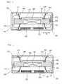
- FIG. 1is a sectional view showing a conventional vibration device
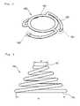
- FIG. 2is a perspective view showing a leaf spring used in the conventional vibration device.
- the conventional vibration deviceincludes a lower case 20 , a coil 30 mounted at the center of the lower case 20 , a circuit board 80 for applying power from outside, a spring holder 70 formed around the outer circumference of the lower case 20 , a leaf spring 60 insert-molded to the spring holder 70 , a vibrating member 90 elastically supported by the leaf spring 60 , and an upper case 10 having a cap shape.
- the vibrating member 90includes a weight 50 with a predetermined weight, and a magnet 40 mounted in a groove formed in a lower surface of the weight 50 , and the vibrating member 90 is fixed to the leaf spring 60 .
- the leaf spring 60has three fixing legs 62 , which are twisted in a pinwheel shape at a ring-shaped loop having a central hollow so that the weight 50 may be combined to an upper portion thereof as if it is inserted therein.
- An end 61 of the fixing leg 62is combined with the spring holder 70 .
- the conventional vibration device configured as aboveis operated as below. If an external power is applied to the coil 30 through the circuit board 80 , a magnetic flux is generated in the coil 30 . By means of interaction between the magnetic flux generated in the coil 30 and the magnetic flux of a magnet 40 faced with the coil 30 , the vibrating member 90 is vibrated vertically.
- the vertical vibration of the vibrating member 90is transferred to the leaf spring 60 , and the vibration transferred by elasticity of the leaf spring 60 is then transferred to the spring holder 70 and the cases 10 and 20 , and then to outside.
- the overall size of the vibration device mounted in the mobile communication terminalshould be reduced. Accordingly, the weight 50 which directly generates vibration becomes also lighter together with decreasing an outer diameter, so a vibrating amount is also decreased.
- the weight 50becomes thicker, the size of the magnet 40 is reduced though a weight of the weight 50 is increased, so the vibrating amount caused by the interaction between the magnet 40 and the coil 30 is even decreased.
- the present inventionprovides a vibration device that can increase a vibrating amount by forming elastic units for enhancing vibration on upper and lower surfaces of a weight so as to elastically support the weight.
- a vibration devicewhich is capable of increasing a vibrating amount by increasing a size of a weight with the use of a cubic elastic unit combined to upper and lower surfaces of the weight instead of a conventional elastic unit combined to a side of the weight.
- a vibration device with a sound functionwhich may increase a vibrating amount by elastically supporting a larger magnetic force generating unit with the use of a cubic elastic unit.
- a vibration devicethat can generate more vibrating amount with the same size in comparison to the conventional vibration device may be obtained.
- a vibration devicethat can generate more vibrating amount with the same size in comparison to the conventional vibration device.
- the vibration device according to the present inventionmay contribute to miniaturization of the mobile terminal.
- FIG. 1is a sectional view showing a conventional vibration device
- FIG. 2is a perspective view showing a leaf spring used in the conventional vibration device
- FIG. 3is a sectional view showing a vibration device according to a first embodiment of the present invention.
- FIG. 4is a sectional view showing another example of the vibration device according to the first embodiment of the present invention.
- FIG. 5is a perspective view showing an example of an elastic unit according to the present invention.
- FIG. 6is a side view showing another example of the elastic unit according to the present invention.
- FIG. 7is a sectional view showing a vibration device according to a second embodiment of the present invention.
- FIG. 8is a sectional view showing another example of the vibration device according to the second embodiment of the present invention.
- FIG. 9is an exploded perspective view showing a vibration device with a sound function according to a third embodiment of the present invention.
- FIG. 10is a sectional view showing the vibration device with a sound function according to the third embodiment of the present invention.
- FIG. 3is a sectional view showing a vibration device according to the first embodiment of the present invention
- FIG. 4is a sectional view showing another example of the vibration device according to the first embodiment of the present invention
- FIG. 5is a perspective view showing an example of an elastic unit used in the vibration device according to the present invention
- FIG. 6is a side view showing another example of the elastic unit used in the vibration device according to the present invention.
- the vibration deviceincludes upper and lower cases 110 and 120 combined with each other, a magnetic force generating unit 130 formed at the center of the upper surface of the lower case 120 , a vibrating unit including a magnet 140 and a weight 150 , the 140 for giving attractive or repulsive force by means of interaction with the magnetic flux generated by the magnetic force generating unit 130 , the weight 150 making one body with the magnet 140 mounted thereto and increasing a vibrating amount with moving vertically by means of interaction between the magnetic force generating unit 130 and the magnet 140 , elastic units 160 combined to the upper and lower surfaces of the weight 150 and extended below and above the weight 150 to elastically support the vibrating unit, and a fixing member 170 for fixing ends 164 of the elastic units 160 .
- the magnetic force generating unit 130may employ a winding coil, and the weight 150 is preferably made of tungsten.
- a magnet mounting groove 151 of a predetermined depthis formed at the center of the lower surface of the weight 150 , and the magnet 140 is inserted and fixed in the magnet mounting groove 151 to make one body with the weight 150 .
- the elastic unit 160is inserted and fixed in elastic unit insert grooves 153 formed on upper and lower surfaces of the weight 150 so as to elastically support the weight 150 .
- the elastic unit 160includes a strip 161 inserted and fixed to the elastic unit insert grooves 153 of the weight 150 and having a closed-curve shape, and a plurality of support legs 163 extended from the strip 161 , as shown in FIG. 5 .
- the support legs 163form a turning curve which descends in an axial direction of the strip 161 , and an end 164 of each support leg 163 is fixed into a fixing groove 171 formed in the fixing member 170 .
- the number of the support legs 163is determined in consideration of a gravity center of the weight 150 elastically supported by the elastic units 160 , and preferably at least two support legs are formed.
- the elastic unit 160may be a conical coil spring 165 as shown in FIG. 6 or a coil spring with a polygonal corn shape.
- the lower or upper surface 166 or 167 of the conical coil spring 165may have various shapes such as a circle, a tetragon, or a pentagon.
- the elastic unit insert groove 153should be formed conforming to the shape of the upper surface 167 of the conical coil spring 165 .
- a diameter (a) of the upper surface 167 which supports the weight 150should be larger than a diameter of the magnet 140
- a diameter (b) of the lower surface 166 which contacts with the upper and lower casesshould be determined to include at least the coil 130 .
- the fixing member 170includes protrusions at the upper and lower ends which are contacted with the upper case 110 and the lower chase 120 , and a recess 173 depressed a predetermined depth at the center.
- the fixing grooves 171 for fixing the end 164 of the elastic unit 160are formed at the ends of the upper and lower protrusions of the fixing member 170 .
- the fixing member 170includes the fixing groove 171 for fixing the end 164 of the elastic unit 160 as shown in FIG. 4 , and it may be separately formed only at a position where the elastic unit 160 is fixed.
- the size of the weight 150may be enlarged in a circumferential direction since the weight 150 is elastically supported by the cubic elastic units 160 and 165 , which are combined on the upper and lower surfaces of the weight 150 , extended above and below the weight 150 and fixed in the fixing groove 171 of the fixing member 170 , instead of a conventional leaf spring which is combined to a side of the weight.
- the vibration device according to the present inventionmay further form a weight extension 154 , which is an extension of the weight 150 in a circumferential direction as much as a predetermined length (W) from the elastic unit insert groove 153 , not to be contacted to an inner side of the recess 173 .
- a weight extension 154is an extension of the weight 150 in a circumferential direction as much as a predetermined length (W) from the elastic unit insert groove 153 , not to be contacted to an inner side of the recess 173 .
- the recess 173 of the fixing member 170should have a vertical space so as not to be contacted with the weight extension 154 as the weight extension 154 extended in a length of W is vertically vibrated.
- FIGS. 3 and 4show that the magnetic force generating unit 130 is formed on the lower case 120 and the magnet 140 is formed to be faced with the magnetic force generating unit 130 , the present invention is not limited to that case, but it is also possible that the magnetic force generating unit 130 is formed on the upper case 110 and the magnet 140 is correspondingly formed.
- the weight 150which forms one body together with the magnet 140 , is canted vertically without interruption, and an vibrating force generated by canting at this time is transferred to outside.
- the vibration devicesince the cubic elastic units are installed on the upper and lower surfaces of the weight 150 instead of a conventional plane elastic unit mounted in a circumferential direction of the weight 150 , there is made a room in a circumferential direction of the weight 150 , so the size of the weight 150 may be enlarged in the circumferential direction. Thus, it is possible to increase a vibrating amount by increasing weight of the weight 150 without reducing a size of the magnet 140 .
- the vibration device according to the first embodiment of the present inventiongives an improved vibrating amount about 1.5 times in comparison to a conventional vibration device with the same size.
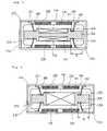
- FIG. 7is a sectional view showing a vibration device according to a second embodiment of the present invention.
- the vibration deviceincludes upper and lower cases 210 and 220 combined with each other, magnetic force generating units 230 formed at the center of the upper and lower cases 210 and 220 , two magnets 240 oppositely formed on each magnetic force generating unit 230 to give attractive or repulsive force by means of interaction with a magnetic flux generated by the magnetic force generating unit 230 , a weight 250 to which the magnets 240 are mounted to make one body and which increases a vibrating amount with moving vertically by means of interaction between the magnetic force generating unit 230 and the magnet 240 , elastic units 260 combined to upper and lower surfaces of the weight 250 and extended above and below the weight 250 to elastically support the weight 250 , and a fixing member 270 for fixing ends of the elastic units 260 .
- the vibration device according to the second embodiment of the present inventionis substantially similar to that of the first embodiment, except that the magnetic force generating units 230 are formed on each of the upper and lower cases 210 and 220 , and the magnets 240 are respectively formed on the upper and lower surfaces of the weight 250 to be opposite to the magnetic force generating unit 230 .
- the magnet 240 formed on the weight 250may be formed to vertically pass through the weight 250 , as shown in FIG. 8 .
- a size of the weightmay be extended as much as a distance (W) from an elastic unit insert groove 253 to a position just before an inner side of a recess 273 of the fixing member 270 .
- the vibration device of this embodimentmay increase a vibrating amount since an additional weight extension 254 is further formed in comparison to the conventional weight.
- the magnetic force generating unit 230such as a winding coil to each of the upper and lower cases 210 and 220 , it is possible to generate stronger attractive and repulsive force between the magnet 240 and the magnetic force generating unit 230 .
- the vibration device according to the second embodiment of the present inventionmay give an increased vibrating amount rather than a conventional one.
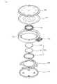
- FIG. 9is an exploded perspective view showing a vibration device with a sound function according to a third embodiment of the present invention
- FIG. 10is a sectional view showing the vibration device with a sound function according to the third embodiment of the present invention.
- the vibration devicehas a sound function for generating a sound in addition to a basic vibrating function.
- the vibration deviceincludes a case 350 , a terminal plate 355 formed on one side of the case 350 to apply an external power thereto, a vibrating plate 370 for generating a sound above the case 350 , a voice coil 330 for generating an electric field below the vibrating plate 370 , a magnetic force generator 340 mounted below the voice coil 330 , a cubic elastic unit 360 for elastically supporting the magnetic force generator 340 , and upper and lower covers 310 and 320 mounted at upper and lower sides of the case 350 to protect the above components.
- the voice coil 330receives a power from the terminal plate 355 and generates an electric field.
- the magnetic force generator 340includes a magnet 342 installed below the voice coil 330 , a yoke 341 formed to surround the magnet 342 , and a plate 343 seated upon the yoke 341 , and generates a magnetic flux.
- the elastic unit 360may employ a cubic spring or a conical spring as shown in FIGS. 5 and 6 .
- the vibration deviceconfigured as above, if current flows along the voice coil 330 , an elastic field is generated, and the magnetic force generator 340 generates a magnetic field.
- the vibrating plate 370 and the magnetic force generator 340integrally combined to the voice coil 330 , are vertically operated.
- the vertically operated vibrating plate 370generates a sound, and the vertical movement of the magnetic force generator 340 is transferred to the elastic unit 360 which elastically supports the magnetic force generator 340 , thereby transferring the vibration to outside.
- the vibration device configured as mentioned above according to the third embodiment of the present inventionmay increase an outer diameter of the magnetic force generator 340 seated on the elastic unit 360 , thereby being capable of generating larger magnetic force, in comparison to a conventional vibration device having a sound function using a leaf spring.
- the vibration device according to the third embodiment of the present inventionmay give a larger vibrating amount than a conventional one.
- the present inventionmay provide a vibration device with a larger vibrating amount since it may increase a size of the weight which generates vibration.
- the vibration device of the present inventionis capable of generating a larger vibrating amount in comparison to a conventional vibration device with the same size, it is possible to reduce a size of the vibration device with keeping a vibrating amount.
- the vibration device of the present inventionis used as a signal reception sensing device of a mobile communication terminal, it is possible to reduce a volume occupied by the vibration device with obtaining a desired vibrating amount, so the mobile communication terminal may be miniaturized.
Landscapes
- Engineering & Computer Science (AREA)
- Power Engineering (AREA)
- Physics & Mathematics (AREA)
- Electromagnetism (AREA)
- Mechanical Engineering (AREA)
- Apparatuses For Generation Of Mechanical Vibrations (AREA)
Abstract
Description
Claims (42)
Priority Applications (1)
| Application Number | Priority Date | Filing Date | Title |
|---|---|---|---|
| US12/407,708US8339224B2 (en) | 2003-07-05 | 2009-03-19 | Vibration device |
Applications Claiming Priority (3)
| Application Number | Priority Date | Filing Date | Title |
|---|---|---|---|
| KR1020030045539AKR100549880B1 (en) | 2003-07-05 | 2003-07-05 | Vibrator structure |
| KR10-2003-0045539 | 2003-07-05 | ||
| PCT/KR2004/001615WO2005004310A1 (en) | 2003-07-05 | 2004-07-01 | Vibration device |
Related Child Applications (1)
| Application Number | Title | Priority Date | Filing Date |
|---|---|---|---|
| US12/407,708ContinuationUS8339224B2 (en) | 2003-07-05 | 2009-03-19 | Vibration device |
Publications (2)
| Publication Number | Publication Date |
|---|---|
| US20060022781A1 US20060022781A1 (en) | 2006-02-02 |
| US7525403B2true US7525403B2 (en) | 2009-04-28 |
Family
ID=33562904
Family Applications (2)
| Application Number | Title | Priority Date | Filing Date |
|---|---|---|---|
| US10/527,755Expired - Fee RelatedUS7525403B2 (en) | 2003-07-05 | 2004-07-01 | Vibration device |
| US12/407,708Expired - Fee RelatedUS8339224B2 (en) | 2003-07-05 | 2009-03-19 | Vibration device |
Family Applications After (1)
| Application Number | Title | Priority Date | Filing Date |
|---|---|---|---|
| US12/407,708Expired - Fee RelatedUS8339224B2 (en) | 2003-07-05 | 2009-03-19 | Vibration device |
Country Status (5)
| Country | Link |
|---|---|
| US (2) | US7525403B2 (en) |
| EP (1) | EP1642377A4 (en) |
| KR (1) | KR100549880B1 (en) |
| CN (2) | CN101345465B (en) |
| WO (1) | WO2005004310A1 (en) |
Cited By (12)
| Publication number | Priority date | Publication date | Assignee | Title |
|---|---|---|---|---|
| US20080015477A1 (en)* | 2006-07-11 | 2008-01-17 | Juvent, Inc. | System and method for a low profile vibrating plate |
| US20100213773A1 (en)* | 2009-02-20 | 2010-08-26 | Aac Acoustic Technologies (Shenzhen) Co., Ltd | Linear Vibrator |
| US20110156849A1 (en)* | 2007-05-15 | 2011-06-30 | Philippe Saint Ger Ag | Method for influencing the magnetic coupling between two bodies at a distance from each other and device for performing the method |
| US20120062048A1 (en)* | 2009-05-14 | 2012-03-15 | Fumiko Kaneko | Magnetic force intensifying electromagnetic driving device |
| JP2012071215A (en)* | 2010-09-27 | 2012-04-12 | Nidec Copal Corp | Vibration actuator |
| US20130033129A1 (en)* | 2011-08-04 | 2013-02-07 | Samsung Electro-Mechanics Co., Ltd. | Linear vibration device |
| US20130142364A1 (en)* | 2011-12-02 | 2013-06-06 | Thomas Paul Heed | Linear Interleaved Magnetic Motor and Loudspeaker Transducer Using Same |
| US20140207268A1 (en)* | 2011-09-05 | 2014-07-24 | Uwe Gutermuth | Operating Arrangement |
| US20140300435A1 (en)* | 2013-04-08 | 2014-10-09 | Tokyo Weld Co., Ltd. | Electromagnetic actuator |
| US10257614B2 (en)* | 2014-07-29 | 2019-04-09 | Yeil Electronics Co., Ltd. | Sensory signal output apparatus |
| US10512937B2 (en)* | 2016-09-14 | 2019-12-24 | Nidec Seimitsu Corporation | Vibration motor |
| US11589167B1 (en)* | 2021-11-10 | 2023-02-21 | Aac Microtech (Changzhou) Co., Ltd. | Multifunctional electromagnetic transducer |
Families Citing this family (48)
| Publication number | Priority date | Publication date | Assignee | Title |
|---|---|---|---|---|
| KR100550904B1 (en)* | 2004-06-23 | 2006-02-13 | 삼성전기주식회사 | Linear Vibration Actuator with Leaf Spring Integral Case |
| TW200629959A (en)* | 2004-09-22 | 2006-08-16 | Citizen Electronics | Electro-dynamic exciter |
| US7538463B2 (en) | 2006-01-10 | 2009-05-26 | Citizen Electronics Co., Ltd. | Vibrator |
| JP2008170974A (en)* | 2006-12-11 | 2008-07-24 | Matsushita Electric Ind Co Ltd | Camera device |
| CN101051774B (en)* | 2007-02-05 | 2011-05-25 | 吴志恒 | Artificial vibrator |
| KR100941292B1 (en) | 2007-11-12 | 2010-02-11 | 엘지이노텍 주식회사 | Vibration motor and its manufacturing method |
| WO2010021482A2 (en)* | 2008-08-18 | 2010-02-25 | Lee In Ho | Horizontal linear vibration device |
| US8461969B2 (en)* | 2009-06-02 | 2013-06-11 | Lg Innotek Co., Ltd. | Dual mode vibrator |
| KR101059599B1 (en)* | 2009-07-01 | 2011-08-25 | 삼성전기주식회사 | Linear vibration motor |
| KR101156787B1 (en)* | 2009-07-27 | 2012-06-18 | 삼성전기주식회사 | Linear Vibrator |
| KR101071419B1 (en)* | 2009-09-29 | 2011-10-10 | 삼성전기주식회사 | Vibration Motor |
| KR101321000B1 (en)* | 2009-09-30 | 2013-10-23 | 자화전자(주) | Linear vibration generating device |
| CN201708677U (en)* | 2009-10-19 | 2011-01-12 | 常州美欧电子有限公司 | Flat linear vibration motor |
| KR101115253B1 (en)* | 2009-10-30 | 2012-02-15 | 자화전자(주) | Linear vibration generator |
| KR101074830B1 (en)* | 2009-12-18 | 2011-10-19 | 주식회사 예일전자 | Sensory signal output apparatus |
| KR101064469B1 (en)* | 2010-04-05 | 2011-09-15 | 엘지이노텍 주식회사 | Vibration motor |
| US8731503B2 (en) | 2010-04-29 | 2014-05-20 | Nokia Corporation | RF performance improvement |
| KR101000757B1 (en)* | 2010-06-09 | 2010-12-13 | 주식회사 비에스이 | Micro speaker with linear vibration structure and manufacturing method |
| KR101130064B1 (en)* | 2010-08-06 | 2012-03-28 | 주식회사 비에스이 | Liner motor |
| CN101958628B (en)* | 2010-09-19 | 2012-07-25 | 歌尔声学股份有限公司 | Micro vibration motor |
| CN201995121U (en)* | 2010-12-21 | 2011-09-28 | 瑞声光电科技(常州)有限公司 | Vibration sound production device |
| KR101803809B1 (en)* | 2011-05-18 | 2017-12-04 | 주식회사 이엠텍 | Linear vibrator |
| CN102290955B (en)* | 2011-06-27 | 2013-07-24 | 歌尔声学股份有限公司 | Miniature vibrating motor |
| KR20130025636A (en)* | 2011-09-02 | 2013-03-12 | 삼성전기주식회사 | Vibration generating device |
| KR101932659B1 (en)* | 2012-09-10 | 2018-12-28 | 주식회사 엠플러스 | vibratior |
| CN204334276U (en)* | 2014-12-23 | 2015-05-13 | 瑞声光电科技(常州)有限公司 | Vibrating motor |
| JP6652502B2 (en)* | 2014-12-24 | 2020-02-26 | ピー・エス・シー株式会社 | Vibration unit |
| CN204761267U (en) | 2015-06-15 | 2015-11-11 | 瑞声光电科技(常州)有限公司 | Linear vibration motor |
| CN204886625U (en)* | 2015-06-15 | 2015-12-16 | 瑞声光电科技(常州)有限公司 | Linear vibration motor |
| CN105163246A (en)* | 2015-08-12 | 2015-12-16 | 歌尔声学股份有限公司 | Voice coil wire, voice coil made of voice coil wire, loudspeaker and vibration motor |
| CN105305761B (en)* | 2015-10-27 | 2017-12-19 | 瑞声光电科技(常州)有限公司 | Vibrating motor |
| CN106026604B (en)* | 2016-06-06 | 2019-06-28 | 歌尔股份有限公司 | A kind of linear vibration motor |
| TWI599149B (en)* | 2016-08-02 | 2017-09-11 | 宏碁股份有限公司 | Vibration generating device |
| CN106374717A (en)* | 2016-08-31 | 2017-02-01 | 浙江省东阳市诚基电机有限公司 | Z-axis vibration square linear motor |
| KR101856461B1 (en) | 2016-11-08 | 2018-05-10 | 주식회사 씨케이머티리얼즈랩 | Tactile actuator |
| CN110087782B (en)* | 2016-12-20 | 2021-06-18 | 三美电机株式会社 | Vibration actuator, wearable terminal and incoming call notification function equipment |
| CN107370323B (en)* | 2017-04-14 | 2019-08-02 | 瑞声科技(新加坡)有限公司 | Vibration device and electronic equipment |
| KR102026401B1 (en)* | 2017-09-29 | 2019-09-27 | 자화전자(주) | Linear vibration generating device |
| CN107659105A (en)* | 2017-10-26 | 2018-02-02 | 池州市弘港科技电子有限公司 | Symmetrical expression linear vibrator |
| KR102032927B1 (en)* | 2018-11-06 | 2019-10-17 | 주식회사 넥스벨 | Linear vibration module |
| US10462574B1 (en)* | 2018-11-30 | 2019-10-29 | Google Llc | Reinforced actuators for distributed mode loudspeakers |
| US11948549B2 (en) | 2019-07-17 | 2024-04-02 | Sound Solutions International Co., Ltd. | Electromagnetic actuator for a display with improved spring arrangement and output device with said actuator |
| CN113727257B (en) | 2020-05-20 | 2024-01-30 | 奥音科技(镇江)有限公司 | Electrodynamic exciter, speaker, electrodynamic transducer and output device |
| CN113727258B (en) | 2020-05-20 | 2024-01-26 | 奥音科技(镇江)有限公司 | Electrodynamic exciter, speaker, electrodynamic transducer and output device |
| CN111641310A (en)* | 2020-06-17 | 2020-09-08 | 池州市弘港科技电子有限公司 | Micro overweight-bass dual-drive low-frequency vibrator |
| CN113262972B (en)* | 2021-05-17 | 2022-03-11 | 湖南大学 | Electromagnetic structure and electromagnetic transducer |
| CN115103275A (en)* | 2022-07-13 | 2022-09-23 | 深圳立讯电声科技有限公司 | Loudspeaker device |
| KR20250122913A (en)* | 2024-02-07 | 2025-08-14 | 풍림전자 주식회사 | Sonic vibration for slim type |
Citations (14)
| Publication number | Priority date | Publication date | Assignee | Title |
|---|---|---|---|---|
| US5107540A (en) | 1989-09-07 | 1992-04-21 | Motorola, Inc. | Electromagnetic resonant vibrator |
| JPH09117721A (en) | 1994-09-28 | 1997-05-06 | Seiko Instr Inc | Vibration module |
| JP2002001215A (en) | 2000-06-16 | 2002-01-08 | Namiki Precision Jewel Co Ltd | Electromagnetic induction type actuator device and portable communication device |
| US6377145B1 (en)* | 1999-03-03 | 2002-04-23 | Tokin Corporation | Vibration actuator having magnetic circuit elastically supported by a spiral damper with increased compliance |
| JP2002263578A (en) | 2001-03-02 | 2002-09-17 | Samsung Electro Mech Co Ltd | Vibroacoustic converter |
| CN1391779A (en) | 1999-12-02 | 2003-01-15 | Nec东金株式会社 | Vibration actuator having elastic member between suspension plate and magnetic circuit device |
| KR20030005288A (en) | 2001-02-19 | 2003-01-17 | 소니 가부시끼 가이샤 | Image processing device |
| JP2003033724A (en) | 2001-07-23 | 2003-02-04 | Citizen Electronics Co Ltd | Electrical-mechanical oscillation converter and small- sized portable device with the same built-in |
| KR100370639B1 (en) | 2000-12-19 | 2003-02-05 | 삼성전기주식회사 | multi actuator |
| KR20030015814A (en) | 2001-08-17 | 2003-02-25 | 삼성전기주식회사 | Multi-function actuator |
| US20030062978A1 (en) | 2001-09-28 | 2003-04-03 | Shicoh Engineering Co., Ltd. | Electromagnetic actuator |
| US6777895B2 (en)* | 2001-11-22 | 2004-08-17 | Matsushita Electric Industrial Co., Ltd. | Vibrating linear actuator |
| US7005811B2 (en)* | 2002-11-29 | 2006-02-28 | Alps Electric Co., Ltd. | Bodily sensed vibration generator system |
| US7038335B2 (en)* | 2004-06-23 | 2006-05-02 | Samsung Electro-Mechanics Co., Ltd. | Vertical vibrator |
Family Cites Families (9)
| Publication number | Priority date | Publication date | Assignee | Title |
|---|---|---|---|---|
| JPS6121699A (en)* | 1984-07-10 | 1986-01-30 | Pioneer Electronic Corp | Electric vibrating transducer |
| KR200160178Y1 (en)* | 1997-08-05 | 1999-11-01 | 이종배 | Alarm and vibrator device |
| US6211775B1 (en)* | 1998-06-15 | 2001-04-03 | Samsung Electro-Mechanics Co., Ltd. | Vibration apparatus capable of generating and externally transmitting a sound wave of audible frequency and transmitting a vibration for notification |
| US6628798B2 (en)* | 1999-04-13 | 2003-09-30 | Nec Tokin Corporation | Vibration actuator having three vibration modes |
| JP2003080171A (en)* | 2001-09-13 | 2003-03-18 | Shicoh Eng Co Ltd | Electromagnetic actuator |
| JP2004105816A (en)* | 2002-09-17 | 2004-04-08 | Tokyo Parts Ind Co Ltd | Electromagnetic acoustics conversion-vibration generator and mobile communicating device equipped therewith |
| TW562363U (en)* | 2002-10-11 | 2003-11-11 | Merry Electronics Co Ltd | Dual magnetic loop voice transceiver |
| US7358633B2 (en)* | 2004-02-23 | 2008-04-15 | Samsung Electro-Mechanics Co., Ltd. | Linear vibration motor using resonance frequency |
| KR100541112B1 (en)* | 2004-07-01 | 2006-01-11 | 삼성전기주식회사 | Weight-bearing vertical vibrator |
- 2003
- 2003-07-05KRKR1020030045539Apatent/KR100549880B1/ennot_activeExpired - Fee Related
- 2004
- 2004-07-01CNCN2008101262218Apatent/CN101345465B/ennot_activeExpired - Fee Related
- 2004-07-01CNCN2004800008154Apatent/CN1701485B/ennot_activeExpired - Fee Related
- 2004-07-01EPEP04748378Apatent/EP1642377A4/ennot_activeWithdrawn
- 2004-07-01WOPCT/KR2004/001615patent/WO2005004310A1/enactiveApplication Filing
- 2004-07-01USUS10/527,755patent/US7525403B2/ennot_activeExpired - Fee Related
- 2009
- 2009-03-19USUS12/407,708patent/US8339224B2/ennot_activeExpired - Fee Related
Patent Citations (16)
| Publication number | Priority date | Publication date | Assignee | Title |
|---|---|---|---|---|
| US5107540A (en) | 1989-09-07 | 1992-04-21 | Motorola, Inc. | Electromagnetic resonant vibrator |
| JPH09117721A (en) | 1994-09-28 | 1997-05-06 | Seiko Instr Inc | Vibration module |
| US5682132A (en)* | 1994-09-28 | 1997-10-28 | Seiko Instruments Inc. | Vibrating module |
| US6377145B1 (en)* | 1999-03-03 | 2002-04-23 | Tokin Corporation | Vibration actuator having magnetic circuit elastically supported by a spiral damper with increased compliance |
| US6850138B1 (en)* | 1999-12-02 | 2005-02-01 | Nec Tokin Corporation | Vibration actuator having an elastic member between a suspension plate and a magnetic circuit device |
| CN1391779A (en) | 1999-12-02 | 2003-01-15 | Nec东金株式会社 | Vibration actuator having elastic member between suspension plate and magnetic circuit device |
| JP2002001215A (en) | 2000-06-16 | 2002-01-08 | Namiki Precision Jewel Co Ltd | Electromagnetic induction type actuator device and portable communication device |
| KR100370639B1 (en) | 2000-12-19 | 2003-02-05 | 삼성전기주식회사 | multi actuator |
| KR20030005288A (en) | 2001-02-19 | 2003-01-17 | 소니 가부시끼 가이샤 | Image processing device |
| JP2002263578A (en) | 2001-03-02 | 2002-09-17 | Samsung Electro Mech Co Ltd | Vibroacoustic converter |
| JP2003033724A (en) | 2001-07-23 | 2003-02-04 | Citizen Electronics Co Ltd | Electrical-mechanical oscillation converter and small- sized portable device with the same built-in |
| KR20030015814A (en) | 2001-08-17 | 2003-02-25 | 삼성전기주식회사 | Multi-function actuator |
| US20030062978A1 (en) | 2001-09-28 | 2003-04-03 | Shicoh Engineering Co., Ltd. | Electromagnetic actuator |
| US6777895B2 (en)* | 2001-11-22 | 2004-08-17 | Matsushita Electric Industrial Co., Ltd. | Vibrating linear actuator |
| US7005811B2 (en)* | 2002-11-29 | 2006-02-28 | Alps Electric Co., Ltd. | Bodily sensed vibration generator system |
| US7038335B2 (en)* | 2004-06-23 | 2006-05-02 | Samsung Electro-Mechanics Co., Ltd. | Vertical vibrator |
Cited By (18)
| Publication number | Priority date | Publication date | Assignee | Title |
|---|---|---|---|---|
| US8795210B2 (en)* | 2006-07-11 | 2014-08-05 | American Medical Innovations, L.L.C. | System and method for a low profile vibrating plate |
| US20080015477A1 (en)* | 2006-07-11 | 2008-01-17 | Juvent, Inc. | System and method for a low profile vibrating plate |
| US20110156849A1 (en)* | 2007-05-15 | 2011-06-30 | Philippe Saint Ger Ag | Method for influencing the magnetic coupling between two bodies at a distance from each other and device for performing the method |
| US20100213773A1 (en)* | 2009-02-20 | 2010-08-26 | Aac Acoustic Technologies (Shenzhen) Co., Ltd | Linear Vibrator |
| US8334624B2 (en)* | 2009-02-20 | 2012-12-18 | Aac Acoustic Technologies (Shenzhen) Co., Ltd. | Horizontal linear vibrator |
| US20120062048A1 (en)* | 2009-05-14 | 2012-03-15 | Fumiko Kaneko | Magnetic force intensifying electromagnetic driving device |
| JP2012071215A (en)* | 2010-09-27 | 2012-04-12 | Nidec Copal Corp | Vibration actuator |
| US9059625B2 (en)* | 2011-08-04 | 2015-06-16 | Samsung Electro-Mechanics Co., Ltd. | Linear vibration device having spring |
| US20130033129A1 (en)* | 2011-08-04 | 2013-02-07 | Samsung Electro-Mechanics Co., Ltd. | Linear vibration device |
| US20140207268A1 (en)* | 2011-09-05 | 2014-07-24 | Uwe Gutermuth | Operating Arrangement |
| US9746847B2 (en)* | 2011-09-05 | 2017-08-29 | Continental Automotive Gmbh | Operating arrangement |
| US8774430B2 (en)* | 2011-12-02 | 2014-07-08 | Thomas Paul Heed | Linear interleaved magnetic motor and loudspeaker transducer using same |
| US20130142364A1 (en)* | 2011-12-02 | 2013-06-06 | Thomas Paul Heed | Linear Interleaved Magnetic Motor and Loudspeaker Transducer Using Same |
| US20140300435A1 (en)* | 2013-04-08 | 2014-10-09 | Tokyo Weld Co., Ltd. | Electromagnetic actuator |
| US9281111B2 (en)* | 2013-04-08 | 2016-03-08 | Tokyo Weld Co., Ltd. | Electromagnetic actuator |
| US10257614B2 (en)* | 2014-07-29 | 2019-04-09 | Yeil Electronics Co., Ltd. | Sensory signal output apparatus |
| US10512937B2 (en)* | 2016-09-14 | 2019-12-24 | Nidec Seimitsu Corporation | Vibration motor |
| US11589167B1 (en)* | 2021-11-10 | 2023-02-21 | Aac Microtech (Changzhou) Co., Ltd. | Multifunctional electromagnetic transducer |
Also Published As
| Publication number | Publication date |
|---|---|
| CN101345465A (en) | 2009-01-14 |
| US20090174510A1 (en) | 2009-07-09 |
| US8339224B2 (en) | 2012-12-25 |
| CN1701485B (en) | 2010-10-13 |
| EP1642377A4 (en) | 2011-05-04 |
| CN1701485A (en) | 2005-11-23 |
| KR20050005596A (en) | 2005-01-14 |
| WO2005004310A1 (en) | 2005-01-13 |
| CN101345465B (en) | 2012-05-30 |
| US20060022781A1 (en) | 2006-02-02 |
| KR100549880B1 (en) | 2006-02-06 |
| EP1642377A1 (en) | 2006-04-05 |
Similar Documents
| Publication | Publication Date | Title |
|---|---|---|
| US7525403B2 (en) | Vibration device | |
| KR100245379B1 (en) | Vibration generating apparatus | |
| CN101902115B (en) | Linear vibrator | |
| US7436088B2 (en) | Electromagnetic exciter | |
| KR200153423Y1 (en) | Alarm and vibrator in the pager | |
| JPH10117472A (en) | Vibration generator for portable equipment | |
| KR100542928B1 (en) | Combined vibration and sound speakers | |
| KR20010060174A (en) | A vibration speaker | |
| CN103379416A (en) | Vibration generator | |
| JP3643791B2 (en) | Multi-actuator | |
| JP3271884B2 (en) | Vibration generator | |
| EP1755358B1 (en) | Multi-function type oscillation actuator and mobile terminal device | |
| JP2004186912A (en) | Electromechanical vibration acoustic transducer and portable terminal equipment | |
| KR100370639B1 (en) | multi actuator | |
| WO2008004729A1 (en) | Vibrator | |
| JP2002200461A (en) | Vibration generator and portable device using the same | |
| KR100330665B1 (en) | Vibration speaker | |
| KR20080001615A (en) | Mini speaker | |
| KR100330663B1 (en) | Vibration speaker | |
| KR100313356B1 (en) | Device for producing vibration and sound | |
| JP7625856B2 (en) | Vibration motor and haptic device | |
| KR100330664B1 (en) | Vibration speaker | |
| KR100330667B1 (en) | Vibration speaker | |
| KR100334669B1 (en) | Vibration speaker | |
| KR20020049602A (en) | Vibration speaker |
Legal Events
| Date | Code | Title | Description |
|---|---|---|---|
| AS | Assignment | Owner name:LG INNOTEK CO., LTD., KOREA, REPUBLIC OF Free format text:ASSIGNMENT OF ASSIGNORS INTEREST;ASSIGNOR:KIM, SANG JIN;REEL/FRAME:016978/0588 Effective date:20041230 | |
| FEPP | Fee payment procedure | Free format text:PAYOR NUMBER ASSIGNED (ORIGINAL EVENT CODE: ASPN); ENTITY STATUS OF PATENT OWNER: LARGE ENTITY | |
| STCF | Information on status: patent grant | Free format text:PATENTED CASE | |
| FEPP | Fee payment procedure | Free format text:PAYER NUMBER DE-ASSIGNED (ORIGINAL EVENT CODE: RMPN); ENTITY STATUS OF PATENT OWNER: LARGE ENTITY Free format text:PAYOR NUMBER ASSIGNED (ORIGINAL EVENT CODE: ASPN); ENTITY STATUS OF PATENT OWNER: LARGE ENTITY | |
| FPAY | Fee payment | Year of fee payment:4 | |
| FEPP | Fee payment procedure | Free format text:PAYER NUMBER DE-ASSIGNED (ORIGINAL EVENT CODE: RMPN); ENTITY STATUS OF PATENT OWNER: LARGE ENTITY Free format text:PAYOR NUMBER ASSIGNED (ORIGINAL EVENT CODE: ASPN); ENTITY STATUS OF PATENT OWNER: LARGE ENTITY | |
| AS | Assignment | Owner name:EM-TECH CO., LTD., KOREA, DEMOCRATIC PEOPLE'S REPU Free format text:ASSIGNMENT OF ASSIGNORS INTEREST;ASSIGNOR:LG INNOTEK CO., LTD.;REEL/FRAME:034253/0176 Effective date:20141114 | |
| FEPP | Fee payment procedure | Free format text:PAT HOLDER CLAIMS SMALL ENTITY STATUS, ENTITY STATUS SET TO SMALL (ORIGINAL EVENT CODE: LTOS); ENTITY STATUS OF PATENT OWNER: LARGE ENTITY | |
| FPAY | Fee payment | Year of fee payment:8 | |
| FEPP | Fee payment procedure | Free format text:ENTITY STATUS SET TO UNDISCOUNTED (ORIGINAL EVENT CODE: BIG.); ENTITY STATUS OF PATENT OWNER: LARGE ENTITY | |
| FEPP | Fee payment procedure | Free format text:MAINTENANCE FEE REMINDER MAILED (ORIGINAL EVENT CODE: REM.); ENTITY STATUS OF PATENT OWNER: LARGE ENTITY | |
| LAPS | Lapse for failure to pay maintenance fees | Free format text:PATENT EXPIRED FOR FAILURE TO PAY MAINTENANCE FEES (ORIGINAL EVENT CODE: EXP.); ENTITY STATUS OF PATENT OWNER: LARGE ENTITY | |
| STCH | Information on status: patent discontinuation | Free format text:PATENT EXPIRED DUE TO NONPAYMENT OF MAINTENANCE FEES UNDER 37 CFR 1.362 | |
| FP | Lapsed due to failure to pay maintenance fee | Effective date:20210428 |