US7525298B2 - Implantable sensor electrodes and electronic circuitry - Google Patents
Implantable sensor electrodes and electronic circuitryDownload PDFInfo
- Publication number
- US7525298B2 US7525298B2US10/973,525US97352504AUS7525298B2US 7525298 B2US7525298 B2US 7525298B2US 97352504 AUS97352504 AUS 97352504AUS 7525298 B2US7525298 B2US 7525298B2
- Authority
- US
- United States
- Prior art keywords
- electrode
- sensor system
- electrode pair
- pair
- circuitry
- Prior art date
- Legal status (The legal status is an assumption and is not a legal conclusion. Google has not performed a legal analysis and makes no representation as to the accuracy of the status listed.)
- Expired - Lifetime, expires
Links
- 238000004891communicationMethods0.000claimsabstractdescription12
- 238000012545processingMethods0.000claimsabstractdescription7
- QVGXLLKOCUKJST-UHFFFAOYSA-Natomic oxygenChemical compound[O]QVGXLLKOCUKJST-UHFFFAOYSA-N0.000claimsdescription23
- 229910052760oxygenInorganic materials0.000claimsdescription23
- 239000001301oxygenSubstances0.000claimsdescription23
- 125000006850spacer groupChemical group0.000claimsdescription21
- 239000000758substrateSubstances0.000claimsdescription21
- 239000003795chemical substances by applicationSubstances0.000claimsdescription17
- 239000003990capacitorSubstances0.000claimsdescription16
- 230000003197catalytic effectEffects0.000claimsdescription16
- 238000005259measurementMethods0.000claimsdescription14
- WQZGKKKJIJFFOK-GASJEMHNSA-NGlucoseNatural productsOC[C@H]1OC(O)[C@H](O)[C@@H](O)[C@@H]1OWQZGKKKJIJFFOK-GASJEMHNSA-N0.000claimsdescription12
- 239000008103glucoseSubstances0.000claimsdescription12
- 239000008280bloodSubstances0.000claimsdescription11
- 210000004369bloodAnatomy0.000claimsdescription11
- 235000019420glucose oxidaseNutrition0.000claimsdescription11
- 238000006243chemical reactionMethods0.000claimsdescription10
- 238000006880cross-coupling reactionMethods0.000claimsdescription8
- 238000007373indentationMethods0.000claimsdescription5
- 229910052710siliconInorganic materials0.000claimsdescription3
- 239000010703siliconSubstances0.000claimsdescription3
- 239000007943implantSubstances0.000description13
- 238000001727in vivoMethods0.000description11
- 230000000694effectsEffects0.000description5
- 238000012360testing methodMethods0.000description5
- 230000002792vascularEffects0.000description5
- 238000010586diagramMethods0.000description4
- 239000012530fluidSubstances0.000description4
- 238000002513implantationMethods0.000description4
- NOESYZHRGYRDHS-UHFFFAOYSA-NinsulinChemical compoundN1C(=O)C(NC(=O)C(CCC(N)=O)NC(=O)C(CCC(O)=O)NC(=O)C(C(C)C)NC(=O)C(NC(=O)CN)C(C)CC)CSSCC(C(NC(CO)C(=O)NC(CC(C)C)C(=O)NC(CC=2C=CC(O)=CC=2)C(=O)NC(CCC(N)=O)C(=O)NC(CC(C)C)C(=O)NC(CCC(O)=O)C(=O)NC(CC(N)=O)C(=O)NC(CC=2C=CC(O)=CC=2)C(=O)NC(CSSCC(NC(=O)C(C(C)C)NC(=O)C(CC(C)C)NC(=O)C(CC=2C=CC(O)=CC=2)NC(=O)C(CC(C)C)NC(=O)C(C)NC(=O)C(CCC(O)=O)NC(=O)C(C(C)C)NC(=O)C(CC(C)C)NC(=O)C(CC=2NC=NC=2)NC(=O)C(CO)NC(=O)CNC2=O)C(=O)NCC(=O)NC(CCC(O)=O)C(=O)NC(CCCNC(N)=N)C(=O)NCC(=O)NC(CC=3C=CC=CC=3)C(=O)NC(CC=3C=CC=CC=3)C(=O)NC(CC=3C=CC(O)=CC=3)C(=O)NC(C(C)O)C(=O)N3C(CCC3)C(=O)NC(CCCCN)C(=O)NC(C)C(O)=O)C(=O)NC(CC(N)=O)C(O)=O)=O)NC(=O)C(C(C)CC)NC(=O)C(CO)NC(=O)C(C(C)O)NC(=O)C1CSSCC2NC(=O)C(CC(C)C)NC(=O)C(NC(=O)C(CCC(N)=O)NC(=O)C(CC(N)=O)NC(=O)C(NC(=O)C(N)CC=1C=CC=CC=1)C(C)C)CC1=CN=CN1NOESYZHRGYRDHS-UHFFFAOYSA-N0.000description4
- 238000000034methodMethods0.000description4
- WQZGKKKJIJFFOK-VFUOTHLCSA-Nbeta-D-glucoseChemical compoundOC[C@H]1O[C@@H](O)[C@H](O)[C@@H](O)[C@@H]1OWQZGKKKJIJFFOK-VFUOTHLCSA-N0.000description3
- 238000009713electroplatingMethods0.000description3
- 230000007774longtermEffects0.000description3
- 108090000790EnzymesProteins0.000description2
- 102000004190EnzymesHuman genes0.000description2
- 102000004877InsulinHuman genes0.000description2
- 108090001061InsulinProteins0.000description2
- 230000008901benefitEffects0.000description2
- 238000003487electrochemical reactionMethods0.000description2
- 229940088598enzymeDrugs0.000description2
- 229940125396insulinDrugs0.000description2
- 238000007747platingMethods0.000description2
- BASFCYQUMIYNBI-UHFFFAOYSA-NplatinumChemical compound[Pt]BASFCYQUMIYNBI-UHFFFAOYSA-N0.000description2
- 230000008569processEffects0.000description2
- 230000004044responseEffects0.000description2
- WHXSMMKQMYFTQS-UHFFFAOYSA-NLithiumChemical compound[Li]WHXSMMKQMYFTQS-UHFFFAOYSA-N0.000description1
- 206010037660PyrexiaDiseases0.000description1
- XUIMIQQOPSSXEZ-UHFFFAOYSA-NSiliconChemical compound[Si]XUIMIQQOPSSXEZ-UHFFFAOYSA-N0.000description1
- BQCADISMDOOEFD-UHFFFAOYSA-NSilverChemical compound[Ag]BQCADISMDOOEFD-UHFFFAOYSA-N0.000description1
- 229910021607Silver chlorideInorganic materials0.000description1
- XLIJUKVKOIMPKW-BTVCFUMJSA-N[O].OC[C@@H](O)[C@@H](O)[C@H](O)[C@@H](O)C=OChemical compound[O].OC[C@@H](O)[C@@H](O)[C@H](O)[C@@H](O)C=OXLIJUKVKOIMPKW-BTVCFUMJSA-N0.000description1
- 230000005540biological transmissionEffects0.000description1
- 230000036760body temperatureEffects0.000description1
- 230000008859changeEffects0.000description1
- 230000003247decreasing effectEffects0.000description1
- 230000001934delayEffects0.000description1
- 230000001419dependent effectEffects0.000description1
- 230000001627detrimental effectEffects0.000description1
- 238000011161developmentMethods0.000description1
- 238000002297emergency surgeryMethods0.000description1
- 238000005516engineering processMethods0.000description1
- -1for exampleSubstances0.000description1
- 238000002347injectionMethods0.000description1
- 239000007924injectionSubstances0.000description1
- 229910052744lithiumInorganic materials0.000description1
- 238000004519manufacturing processMethods0.000description1
- 239000000463materialSubstances0.000description1
- 238000012986modificationMethods0.000description1
- 230000004048modificationEffects0.000description1
- 229910052697platinumInorganic materials0.000description1
- 230000001681protective effectEffects0.000description1
- 230000000284resting effectEffects0.000description1
- 238000007789sealingMethods0.000description1
- 229910052709silverInorganic materials0.000description1
- 239000004332silverSubstances0.000description1
- HKZLPVFGJNLROG-UHFFFAOYSA-Msilver monochlorideChemical compound[Cl-].[Ag+]HKZLPVFGJNLROG-UHFFFAOYSA-M0.000description1
- 238000007920subcutaneous administrationMethods0.000description1
- 230000001360synchronised effectEffects0.000description1
- 238000012546transferMethods0.000description1
- 210000003462veinAnatomy0.000description1
Images


Classifications
- A—HUMAN NECESSITIES
- A61—MEDICAL OR VETERINARY SCIENCE; HYGIENE
- A61N—ELECTROTHERAPY; MAGNETOTHERAPY; RADIATION THERAPY; ULTRASOUND THERAPY
- A61N1/00—Electrotherapy; Circuits therefor
- A61N1/02—Details
- A61N1/04—Electrodes
- A61N1/05—Electrodes for implantation or insertion into the body, e.g. heart electrode
- A—HUMAN NECESSITIES
- A61—MEDICAL OR VETERINARY SCIENCE; HYGIENE
- A61B—DIAGNOSIS; SURGERY; IDENTIFICATION
- A61B5/00—Measuring for diagnostic purposes; Identification of persons
- A61B5/24—Detecting, measuring or recording bioelectric or biomagnetic signals of the body or parts thereof
- A61B5/25—Bioelectric electrodes therefor
- A61B5/279—Bioelectric electrodes therefor specially adapted for particular uses
- A61B5/28—Bioelectric electrodes therefor specially adapted for particular uses for electrocardiography [ECG]
- A61B5/283—Invasive
- G—PHYSICS
- G01—MEASURING; TESTING
- G01R—MEASURING ELECTRIC VARIABLES; MEASURING MAGNETIC VARIABLES
- G01R27/00—Arrangements for measuring resistance, reactance, impedance, or electric characteristics derived therefrom
- G01R27/02—Measuring real or complex resistance, reactance, impedance, or other two-pole characteristics derived therefrom, e.g. time constant
- G01R27/14—Measuring resistance by measuring current or voltage obtained from a reference source
Definitions
- the present inventionrelates to the field of sensor electronics and, in particular, to implantable sensor electrodes and implantable electronic circuits for sensors.
- physiological parameter sensorsare available that may be implanted in vivo and left in an in vivo environment for six months to a year and longer. Such extended lengths of time in an in vivo environment have taxed previously available electronic circuitry used in connection with the physiological parameter sensors.
- physiological parameter sensorsthat may be placed in a vascular environment or other environment that may subject a physiological parameter sensor to constant fluid environments has increased the burden on electrodes used in conjunction with a biomolecule that may be part of the physiological parameter sensor. Because multiple electrodes may be used in physiological parameter sensing applications, fluids such as, for example, blood, may create multiple conductive paths across electrodes that compromise the integrity of measurements being made with the electrodes. Electrode configuration and associated circuitry known up to this point have been ill-equipped to handle the demands of such an environment.
- a physiological parameter sensormay be implanted in vivo
- a power sourcesuch as, for example, a lithium battery
- Such short term sensorsmay have been designed, for example, for emergency use in surgical applications where the intent was to keep the sensor powered even in storage.
- a hospitalcould store the sensors, implant them during emergency surgery, and expect to get sensor readouts immediately.
- storing a sensor with an activated power sourcemay deplete the power source to such an extent that using the sensor for long term in vivo implantation may be impractical and even unadvisable.
- Implantable, in vivo automated systemsrequire not only extended term power requirements for powering an implanted power sensor, but also require increased power availability for the circuitry used to obtain and process sensor signals.
- Embodiments of the present inventionrelate to sensor electrodes and sensor electronics interfaced to the sensor electrodes.
- Embodiments of the present inventioninclude an electronic circuit for sensing an output of a sensor including at least one electrode pair for sensing a parameter.
- the at least one electrode pairmay have a first electrode and a second electrode, wherein the first electrode wraps around the second electrode.
- the electronic circuitmay contain circuitry for processing the parameter.
- the parameter sensed by the electrode pairmay be a physiological parameter such as, for example, glucose or oxygen.
- the first electrodemay wrap around the second electrode in a U-shaped fashion or may surround three sides of the second electrode.
- the layout of the first electrode and a second electrodemay be such that it minimizes cross coupling between the first electrode and the second electrode.
- the electronic circuitmay include a reference electrode for setting a reference voltage for the at least one electrode pair.
- the reference voltagemay be set to about 0.5 volts.
- the circuitrymay include a line interface for interfacing with input/output lines; a rectifier in parallel with the line interface; a counter connected to the line interface; and a data converter connected to the counter and the at least one electrode pair.
- Control logicmay be connected to the counter and the line interface.
- the control logicmay include a state machine and a state decoder connected to the state machine.
- the control logicmay include a microprocessor.
- the rectifiermay transfer power from communication pulses to a capacitor.
- the capacitormay power the electronic circuit using power stored from the communication pulses.
- the data convertermay be an analog-to-digital converter, a voltage-to-frequency converter, or a current-to-frequency converter. If the data converter is a current-to-frequency converter, an output of the current-to-frequency converter may be scaled using a prescaler before connecting to the counter.
- the prescalermay be a divide-by-16 prescaler.
- the circuitrymay also include a temperature sensor for reading a temperature of an environment and a voltage reference for applying a voltage to a reference electrode.
- switched capacitor circuitsmay be used as resistors in the electronic circuit.
- FIG. 1shows a general block diagram of an electronic circuit for sensing an output of a sensor according to an embodiment of the present invention.
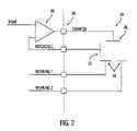
- FIG. 2shows an electronic configuration of the sensor electrodes according to an embodiment of the present invention.
- FIG. 3shows a graph of current versus voltage for varying levels of oxygen according to an embodiment of the present invention.
- FIG. 4shows a physical electrode layout to minimize the effect of cross coupling between counter electrodes and working electrodes according to an embodiment of the present invention.
- FIG. 5shows a detailed block diagram of an electronic circuit according to an embodiment of the present invention.
- FIG. 6shows a transmitted pulse waveform according to an embodiment of the present invention.
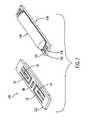
- FIG. 7shows a substrate having a first side which contains an electrode configuration and a second side which contains electronic circuitry according to an embodiment of the present invention.
- FIG. 8shows an electrode side of a sensor substrate used with the spacers according to an embodiment of the present invention.
- FIG. 1shows a general block diagram of an electronic circuit for sensing an output of a sensor according to an embodiment of the present invention.
- At least one pair of sensor electrodes 10may interface to a data converter 12 , the output of which may interface to a counter 14 .
- the counter 14may be controlled by control logic 16 .
- the output of the counter 14may connect to a line interface 18 .
- the line interface 18may be connected to input and output lines 20 and may also connect to the control logic 16 .
- the input and output lines 20may also be connected to a power rectifier 22 .
- the sensor electrodes 10may be used in a variety of sensing applications and may be configured in a variety of ways.
- the sensor electrodes 10may be used in physiological parameter sensing applications in which some type of biomolecule is used as a catalytic agent.
- the sensor electrodes 10may be used in a glucose and oxygen sensor having a glucose oxidase enzyme catalyzing a reaction with the sensor electrodes 10 .
- the sensor electrodes 10along with a biomolecule or some other catalytic agent, may be placed in a human body in a vascular or non-vascular environment.
- the sensor electrodes 10 and biomoleculemay be placed in a vein and be subjected to a blood stream, or may be placed in a subcutaneous or peritoneal region of the human body.
- FIG. 2shows an electronic configuration of the sensor electrodes 10 according to an embodiment of the present invention.
- An op amp 30 or other servo controlled devicemay connect to sensor electrodes 10 through a circuit/electrode interface 38 .
- the op amp 30may attempt to maintain a positive voltage between a reference electrode 32 and a working electrode 34 by adjusting the voltage at a counter electrode 36 .
- the voltage applied at an input of the op amp 30 and thus set at the reference electrode 32may be approximately 0.5 volts.
- Currentmay then flow from a counter electrode 36 to a working electrode 34 . Such current may be measured to ascertain the electrochemical reaction between the sensor electrodes 10 and the biomolecule of a sensor that has been placed in the vicinity of the sensor electrodes 10 and used as a catalyzing agent.
- currentmay flow from a counter electrode 36 to a working electrode 34 only if there is oxygen in the vicinity of the enzyme and the sensor electrodes 10 .
- the voltage set at the reference electrode 32is maintained at about 0.5 volts
- the amount of current flowing from a counter electrode 36 to a working electrode 34has a fairly linear relationship with unity slope to the amount of oxygen present in the area surrounding the enzyme and the electrodes.
- increased accuracy in determining an amount of oxygen in the bloodmay be achieved by maintaining the reference electrode 32 at about 0.5 volts and utilizing this region of the current-voltage curve for varying levels of blood oxygen.
- FIG. 3A graph of current versus voltage for varying levels of oxygen may be seen in FIG. 3 .
- Different embodiments of the present inventionmay utilize different sensors having biomolecules other than a glucose oxidase enzyme and may, therefore, have voltages other than 0.5 volts set at the reference electrode.
- more than one working electrode 34may be used. However, although current may normally flow out of the op amp 30 toward the counter electrode 36 and then toward a corresponding working electrode 34 , in some applications where more than one working electrode 34 is used, current from a counter electrode 36 may be coupled to an unintended working electrode 34 . This phenomenon may occur because some environments in which the sensor may be used may provide multiple conductive paths from a counter electrode 36 to any of a plurality of working electrodes 34 . For example, when a sensor having a glucose oxidase enzyme is used in glucose and oxygen sensing applications and is placed in a vascular environment, blood surrounding the sensor may create a conductive path from a counter electrode 36 to any of a plurality of working electrodes 34 .
- the sensor electrodes 10may be configured to minimize the effect of cross coupling between counter electrodes 36 and working electrodes 34 .
- FIG. 4shows a physical electrode layout to minimize the effect of cross coupling between counter electrodes and working electrodes according to an embodiment of the present invention.
- Each counter electrode 40 , 42wraps around a working electrode 44 , 46 in a U-shaped fashion.
- a reference electrode 48may be positioned between the counter electrodes 40 , 42 .
- cross coupling between a first counter electrode 40 and a second working electrode 46 and a second counter electrode 42 and a first working electrode 44may be minimized.
- the first and second counter electrodes 40 , 42may be electronically coupled such that the voltage or electric potential of the counter electrodes 40 , 42 is equivalent.
- Electroplatingmay be accomplished with any of a variety of electroplating materials that are common in the industry, such as, for example, platinum, silver, silver chloride and the like.
- the electronic circuitmay contain plating circuitry that may be used for this purpose.
- the electronic circuitmay contain a plating circuit that is utilized only during the manufacturing process to facilitate electroplating of the electrodes.
- the sensor electrodes 10may interface to a data converter 12 .
- the data converter 12may be any type of analog-to-digital converter suitable for converting an electronic parameter coming from the sensor electrodes 10 into a form suitable for use by the remainder of the electronic circuit.
- the data convertermay convert current to digital data or voltage to digital data.
- the data convertermay convert current to frequency.
- a current-to-frequency converter suitable for use in an embodiment of the present inventionis disclosed in U.S. Pat. No. 5,917,346, Low Power Current-to-Frequency Converter Circuit For Use In Implantable Sensors, by John C. Gord, assigned to the Alfred E. Mann Foundation, which is incorporated herein by reference.
- the counter 14may be any counter commonly used in the industry such as, for example, a ripple counter.
- the control logic 16may be any control logic that facilitates accurate operation of the counter 14 .
- the counter and control logicmay operate in a synchronous or asynchronous mode.
- the counter 14 and control logic 16may be implemented in a variety of ways, such as, for example, with discrete devices or with a microprocessor.
- the line interface 18may receive information in a variety of forms such as, for example, in pulses, from a remotely located implant unit or other device to which the electronic circuit is interfaced.
- the line interface 18may generate data and clock signals for use by other parts of the electronic circuitry from such information.
- the line interface 18may also send information in the form of pulses, for example, back to the implant unit or other device to which it is interfaced.
- the power rectifier 22may take power from communication signals incident on the input lines 20 and store such power on a storage device such as, for example, a capacitor. According to embodiments of the present invention, there is no internal energy generating device such as, for example, a battery, resident in the electronic circuit. Power is derived from the communication signals using the power rectifier 22 . Thus, the electronic circuit may be used for long term sensing applications since there is no concern for depletion of an energy generating device such as, for example, a battery, within the electronic circuit.
- a power rectifier circuit suitable for use in an embodiment of the present inventionis disclosed in U.S. Pat. No. 5,999,849, Low Power Rectifier Circuit For Implantable Medical Device, by John C. Gord et al, assigned to the Alfred E. Mann Foundation, which is incorporated herein by reference.
- FIG. 5shows a more detailed block diagram of an electronic circuit according an embodiment of the present invention.
- Input/output lines 20connect to a line interface 18 and power rectifier 22 and provide a communications link between the electronic circuit and a remotely located implant unit or other device.
- a remotely located implant unit or other devicemay communicate with the electronic circuit using a series of bipolar pulses transmitted across the input/output lines.
- a transmitted pulse waveformmay be seen in FIG. 6 .
- Each bipolar pulse 50 , 52 , 54 , 56may represent one bit of data from the remotely located implant unit or other device communicating with the electronic circuit.
- Each bipolar pulse 50 , 52 , 54 , 56may comprise a positive and a negative level.
- a binary onemay be designated by a positive level followed by a negative level.
- a positive level not followed by a negative levelmay designate a binary zero.
- transmit pulse amplitudesmay be between 2.3 volts and 3.6 volts.
- a first pulse 50 transmittedis a positive pulse and is followed by a negative pulse.
- the pair of pulses 50 , 52indicate a binary one according to an embodiment of the present invention.
- the second pair of pulses 54 , 56 in FIG. 6is a negative pulse followed by a positive pulse.
- the second pair of pulses 54 , 56represent a binary zero.
- a zero voltage levelmay exist between positive and negative pulses.
- a pulse width 58may be approximately 1.9 micro seconds.
- the pulsesmay have a pulse repetition rate of 4,096 hertz, corresponding to a period 60 of approximately 244 microseconds.
- the electronic circuitmay be implemented with a variety of communication delays built in so that the integrity of data transmissions may be increased.
- a 152 microsecond delay after receipt of a pair of transmitted pulsesmay be used for ignoring other pulses on the input/output lines.
- confusion as to the intended recipient of the pulsesmay be decreased if, for example, there are a plurality of electronic circuits using the same input/output lines or of the electronic circuit has put its own pulses onto the input/output lines.
- the electronic circuitmay respond in a variety of ways depending on the opcode or data received. For example, the electronic circuit may respond by outputting a counter value, a trim setting value, a mode status, a channel setting, an identification number that has been permanently etched onto the circuit, or the like. According to an embodiment of the present invention, the electronic circuit may respond in the form of unipolar pulses. For example, if the response value is a binary one, the electronic circuit may set a logic high using a positive pulse for a duration from between one to ten microseconds, nominally 44 microseconds after the first edge of the bipolar pulse received from the remotely located implant unit or other device.
- the amplitude of the pulses sent by the electronic device to the remotely located implant unit or other devicemay be between one volt and 3.6 volts. If the response from the electronic circuit is a binary zero, no pulse may be sent by the electronic circuit to the remotely located implant unit or other device.
- the input lines 20may be fed to a power rectifier 22 which uses pulses incident on the input lines 20 to charge a capacitor 19 .
- Electrical charge stored in the capacitor 19 extracted from the communication pulses on the input lines 20may be used to power the electronic circuit.
- the capacitor 19may also act as a low pass filter for the electronic circuit to reduce voltage ripple. According to an embodiment of the present invention, using a pulse width of 2 microseconds every 244 microseconds, the capacitance may be about 0.033 microfarads. Because a capacitor of this size may be too large for an integrated device, if the electronic circuit is fabricated as an integrated circuit, the capacitor 19 may be a discrete capacitor external to the electronic circuit. According to an embodiment of the present invention, the capacitor may be charged to +/ ⁇ 3 volts.
- the input lines 20may also be connected to a line interface 18 which, according to an embodiment of the present invention, may receive information in a form such as, for example, bipolar pulses from a remotely located implant unit or other device.
- the line interface 18may also generate data and clock signals and may also send unipolar pulses back to the remotely located implant unit or other device.
- a state machine 70 and state decoder 72may be connected to the line interface 18 .
- Data and clock signals generated by the line interface 18may be used by the state machine 70 to extract data and to determine the nature of the bipolar pulses received on the input lines 20 .
- the state machine 70may provide a variety of functions for the electronic circuit. For example, the state machine 70 may generate system clocks, clear counters, check parity and the like.
- the state machine 70may also decode opcodes and data. Decoded opcodes may designate a variety of functions such as, for example, latching a new multiplexer channel setting, setting trim values and setting a test mode.
- the state decoder 72may be used to decode counter outputs.
- the state machine 70 and state decoder 72may include a power-on clear circuit 74 .
- the power-on clear circuit 74may be a typical RC type pulse generation circuit having a 50 picofarad capacitor, a transistor acting as a resistor, and two inverters to square a pulse.
- the state machine 70 and state decoder 72may interface to an input latch 76 .
- the input latch 76may be used to latch addresses, opcodes and data used in a command.
- the input latch 76may feed a trim latch 78 , an address matching circuit 80 and a channel latch 82 .
- the channel latch 82may comprise a plurality of latches with data inputs from the input latch 76 .
- the channel latch 82may be used to control prescalers and multiplexers.
- the trim latch 78may also consist of a plurality of latches. Inputs to the trim latch 78 may contain trim sitting data. Once latched, the trim sitting may be maintained until the next trim setting operation or until a power-on reset occurs.
- trim settingsmay have secret handshakes. Because trim settings may greatly affect the operation of the electronic circuit, care may be taken to minimize errors when setting trim voltages. For example, the electronic circuit may receive specific commands with no other commands in between before trim voltages are set.
- the address matching circuit 80may be used to verify that instructions and data sent to an electronic circuit are being received by the intended electronic circuit. In applications where multiple sensors, sensor electrodes and sensor electronic circuits are used, the address matching circuit 80 can verify that each electronic circuit receives instructions and data intended for it. For example, in some applications, several electronic circuits may be daisy chained together. Because each electronic circuit may have a unique address, instructions and data sent over a serial bus may be received by each electronic circuit but intended for only one electronic circuit. The address matching circuit 80 will read the address for which the instructions and data are intended and compare that address to the address of the electronic circuit in which the address matching circuit 80 is resident. If the address read by the address matching circuit 80 matches the address of the electronic circuit, the instructions and data will be used by the electronic circuit. If the address read by the address matching circuit 80 does not match the address of the electronic circuit, the instructions and data will be ignored by the electronic circuit.
- the channel latch 82may feed a channel decoder 84 .
- the channel decoder 84may decode channel bytes from the channel latch 82 into channel select signals.
- the channel decoder 84 signalsmay then be used to control an analog multiplexer 86 for the selection of auxiliary signals for measurement.
- the analog multiplexer 86may multiplex auxiliary signals to a data converter for measurement.
- the analog multiplexer 86may be an eight channel CMOS multiplexer. If voltage signals are multiplexed out of the analog multiplexer, they may be directed to a switched capacitor resistor 88 for conversion of the voltages to currents, thereby putting the voltages in a form that may be measured by current to frequency converters.
- a discrete resistor or a transistor used as a resistormay be used in place of the switched capacitor resistor 88 , the switched capacitor resistor 88 is used because it is generally smaller than other types of resistors and takes up less space in the electronic circuit.
- a temperature sensor 90may be fed into the analog multiplexer 86 providing an output current that is function of temperature.
- nominal output current from the temperature sensor 90may be 50 nanoamps and may change by 1 nanoamp per degree Celsius.
- the temperature sensor 90may be included in the electronic circuit to provide proper calibration of the electronic circuit. For example, a patient with a fever may cause a different glucose/oxygen reaction than a patient with a normal body temperature. The temperature sensor 90 may be used to compensate for this difference.
- current-to-frequency 92 , 94 , 96 convertersmay be used in the electronic circuit shown in FIG. 5 .
- Current-to-frequency converters 92 , 94 , 96provide an easy method by which to count cycles, consume very low power, automatically average, and make current measurement relatively inexpensive.
- current-to-frequency converters 92 , 94 , 96are conducive to measuring current through the working electrodes 34 while holding the working electrodes 34 at ground without using a negative power supply. Current passing from the counter electrodes 36 to the working electrodes 34 tends to drive the working electrodes 34 above ground.
- the current-to-frequency converters 92 , 94 , 96emit negative charge packets.
- the working electrodes 34may be maintained at ground. This is because the negative charge packets emitted by the current-to-frequency converters 92 , 94 , 96 tend to offset the current from the counter electrodes 36 tending to drive the working electrodes 34 above ground.
- the current-to-frequency 92 , 94 , 96 convertersmay be calibrated in a variety of ways. According to an embodiment of the present invention, the current-to-frequency 92 , 94 , 96 converters may calibrated at about 100 counts/sec/nanoamp. The calibration of the current-to-frequency 92 , 94 , 96 converters may depend on a variety of factors including, without limitation, the length of the counting time and any current-to-frequency conversion factors.
- the current-to-frequency converters 92 , 94 , 96may feed prescalers 98 , 100 , 102 .
- the prescalers 98 , 100 , 102may be used to modify the output of the current-to-frequency converters 92 , 94 , 96 .
- the prescalers 98 , 100 , 102may simply be divide by 16 circuits that reduces the number of counts seen by the measurement counters 104 , 106 , 108 . In this way, the burden on the measurement counters 104 , 106 , 108 is minimized and risk of the measurement counters 104 , 106 , 108 overflowing is reduced.
- the electronic circuitmay be designed such that use of the prescalers 98 , 100 , 102 is optional by setting a flag or other indicator.
- the measurement counters 104 , 106 , 108may be used to measure the output of the current-to-frequency converters 92 , 94 , 96 or to measure auxiliary signals. By knowing the count of the frequency output by the current-to-frequency converters 92 , 94 , 96 , the length of the counting time, and any current-to-frequency conversion factors used by the current-to-frequency converters 92 , 94 , 96 , the current generated by the sensor may be calculated.
- the measurement counters 104 , 106 , 108may contain their own multiplexers.
- the measurement counters 104 , 106 , 108 , or the multiplexers on the measurement counters 104 , 106 , 108may feed a general output multiplexer 110 which sends count values to the line interface 18 .
- the line interface 18may then send these count values back to a remotely located implant unit or other device.
- the electronic circuitmay also contain a voltage reference 112 .
- the voltage reference 112may take a variety of forms.
- the voltage reference 112may be a band gap reference circuit and may provide bias voltages used to provide known currents to transistors.
- the electronic circuitmay also contain a variety of other elements.
- the electronic circuitmay contain a test pad used for test purposes.
- a clockmay be fed into the test pad to exercise the counters.
- the test padmay also be configured as an output so that on-chip voltage references may be measured.
- the electronic circuitmay also contain variable bias circuitry.
- variable bias circuitryIn order for the electronic circuit to operate quickly, a significant amount of bias current may be required to drive the transistors included in the circuit. However, there may be extended periods of time when the electronic circuit engages in very little activity. During periods of little activity, the variable bias circuitry may decrease the amount of bias current available to the electronic circuit. In addition, as soon as the voltage on the input lines varies by a threshold amount such as, for example, a volt or so, the variable bias circuitry may increase the amount of-bias current available to the electronic circuit so that all of the functions of the electronic circuit may operate quickly. Thus, the variable bias circuitry may provide a dynamically adjustable bias current for the electronic circuit. The variable bias circuitry may anticipate pulses being received on the input lines so that, when the pulses arrive at the electronic circuit, an adequate amount of bias current is available for fast operation of the electronic circuit.
- the electronic circuitmay be implemented in a variety of ways.
- the electrodes and the circuitrymay be affixed to a single substrate.
- FIG. 7shows a substrate 120 having two sides, a first side 122 of which contains an electrode configuration and a second side 124 of which contains electronic circuitry.
- a first side 122 of the substratecomprises two counter electrode-working electrode pairs 40 , 42 , 44 , 46 on opposite sides of a reference electrode 48 .
- a second side 124 of the substratecomprises electronic circuitry.
- the electronic circuitrymay be enclosed in a hermetically sealed casing 126 , providing a protective housing for the electronic circuitry.
- the sensor substrate 120may be inserted into a vascular environment or other environment which may subject the electronic circuitry to fluids.
- the electronic circuitrymay operate without risk of short circuiting by the surrounding fluids.
- pads 128are also shown in FIG. 7 to which the input and output lines of the electronic circuitry may be connected.
- the electronic circuitryitself may be fabricated in a variety of ways. According to an embodiment of the present invention, the electronic circuitry may be fabricated as an integrated circuit using techniques common in the industry.
- FIG. 8shows an electrode side of a sensor substrate 120 used with the spacers 130 according to an embodiment of the present invention.
- the embodiment shown in FIG. 8may be used for physiological parameter sensing such as, for example, glucose sensing in the human body.
- the spacer 130may be placed on top of the electrodes 40 , 42 , 44 , 46 , 48 . If the spacer 130 is made of silicon, for example, the spacer 130 may pass oxygen but will not pass glucose.
- a glucose oxidase enzymemay be placed in the indentation 132 of the spacer 130 , thereby resting over a second counter electrode-working electrode pair 42 , 46 .
- Oxygen passing through the silicon spacer 130 and reacting with a first counter electrode-working electrode pair 40 , 44may be read by the current-to-frequency converters and used to establish a reference amount of oxygen in the blood.
- Glucose reacting with the glucose oxidase enzyme seated over the second counter electrode-working electrode pair 42 , 46will tend to use up oxygen, leaving less oxygen available for reaction with the second counter electrode-working electrode pair 42 , 46 . Nonetheless, the remaining amount of oxygen will still react with the second counter electrode-working electrode pair 42 , 46 , and this value may be read by the current-to-frequency converter to which it is connected.
- the values out of each current-to-frequency to convertermay be read and the differing amounts of oxygen may be used to determine the amount of glucose in the blood.
- the amount of glucose in the bloodmay be used to automatically deliver insulin to a patient using an implantable pump or other device.
Landscapes
- Health & Medical Sciences (AREA)
- Life Sciences & Earth Sciences (AREA)
- Public Health (AREA)
- Cardiology (AREA)
- Heart & Thoracic Surgery (AREA)
- Engineering & Computer Science (AREA)
- Biomedical Technology (AREA)
- Veterinary Medicine (AREA)
- Animal Behavior & Ethology (AREA)
- General Health & Medical Sciences (AREA)
- Nuclear Medicine, Radiotherapy & Molecular Imaging (AREA)
- Radiology & Medical Imaging (AREA)
- Physics & Mathematics (AREA)
- Biophysics (AREA)
- Pathology (AREA)
- Medical Informatics (AREA)
- Molecular Biology (AREA)
- Surgery (AREA)
- Measurement Of The Respiration, Hearing Ability, Form, And Blood Characteristics Of Living Organisms (AREA)
- Measurement And Recording Of Electrical Phenomena And Electrical Characteristics Of The Living Body (AREA)
- Electrotherapy Devices (AREA)
Abstract
Description
This application is a continuation of application Ser. No. 10/034,338 filed Dec. 28, 2001 and issued as U.S. Pat. No. 6,809,507 on Oct. 26, 2004, which in turn claims the benefit of prior filed U.S. Provisional No. 60/335,652 filed Oct. 23, 2001, the contents of each are incorporated by reference herein.
1. Field of the Invention
The present invention relates to the field of sensor electronics and, in particular, to implantable sensor electrodes and implantable electronic circuits for sensors.
2. Description of Related Art
The development of sensors that can survive for extended periods in less than ideal environments has increased the burden on associated electronics used to obtain and process signals received from such sensors. For example, in the medical device field, physiological parameter sensors are available that may be implanted in vivo and left in an in vivo environment for six months to a year and longer. Such extended lengths of time in an in vivo environment have taxed previously available electronic circuitry used in connection with the physiological parameter sensors.
In addition, the availability of physiological parameter sensors that may be placed in a vascular environment or other environment that may subject a physiological parameter sensor to constant fluid environments has increased the burden on electrodes used in conjunction with a biomolecule that may be part of the physiological parameter sensor. Because multiple electrodes may be used in physiological parameter sensing applications, fluids such as, for example, blood, may create multiple conductive paths across electrodes that compromise the integrity of measurements being made with the electrodes. Electrode configuration and associated circuitry known up to this point have been ill-equipped to handle the demands of such an environment.
Moreover, the extended periods of time in which a physiological parameter sensor may be implanted in vivo have placed extra demands on the power sources driving the sensor electrodes and sensor electronics. For example, previous sensor technology, which may have been designed for relatively short term in vivo implantation of a sensor, may have included a power source, such as, for example, a lithium battery, for in vivo implantation along with the sensor. Such short term sensors may have been designed, for example, for emergency use in surgical applications where the intent was to keep the sensor powered even in storage. Thus, a hospital could store the sensors, implant them during emergency surgery, and expect to get sensor readouts immediately. However, with the advent of sensors for long term in vivo implantation, storing a sensor with an activated power source may deplete the power source to such an extent that using the sensor for long term in vivo implantation may be impractical and even unadvisable.
In addition, the demand for enhanced in vivo signal processing has put even greater demands on an already overburdened in vivo power source. Implantable, in vivo automated systems require not only extended term power requirements for powering an implanted power sensor, but also require increased power availability for the circuitry used to obtain and process sensor signals.
Embodiments of the present invention relate to sensor electrodes and sensor electronics interfaced to the sensor electrodes.
Embodiments of the present invention include an electronic circuit for sensing an output of a sensor including at least one electrode pair for sensing a parameter. The at least one electrode pair may have a first electrode and a second electrode, wherein the first electrode wraps around the second electrode. The electronic circuit may contain circuitry for processing the parameter. The parameter sensed by the electrode pair may be a physiological parameter such as, for example, glucose or oxygen.
The first electrode may wrap around the second electrode in a U-shaped fashion or may surround three sides of the second electrode. The layout of the first electrode and a second electrode may be such that it minimizes cross coupling between the first electrode and the second electrode.
The electronic circuit may include a reference electrode for setting a reference voltage for the at least one electrode pair. The reference voltage may be set to about 0.5 volts.
In addition, the circuitry may include a line interface for interfacing with input/output lines; a rectifier in parallel with the line interface; a counter connected to the line interface; and a data converter connected to the counter and the at least one electrode pair. Control logic may be connected to the counter and the line interface. The control logic may include a state machine and a state decoder connected to the state machine. The control logic may include a microprocessor.
In the electronic circuit, the rectifier may transfer power from communication pulses to a capacitor. The capacitor may power the electronic circuit using power stored from the communication pulses.
The data converter may be an analog-to-digital converter, a voltage-to-frequency converter, or a current-to-frequency converter. If the data converter is a current-to-frequency converter, an output of the current-to-frequency converter may be scaled using a prescaler before connecting to the counter. The prescaler may be a divide-by-16 prescaler.
The circuitry may also include a temperature sensor for reading a temperature of an environment and a voltage reference for applying a voltage to a reference electrode. In addition, switched capacitor circuits may be used as resistors in the electronic circuit.
These and other objects, features, and advantages of embodiments of the invention will be apparent to those skilled in the art from the following detailed description of embodiments of the invention when read with the drawings and appended claims.
In the following description of preferred embodiments, reference is made to the accompanying drawings which form a part hereof, and in which are shown by way of illustration specific embodiments in which the invention may be practiced. It is to be understood that other embodiments may be utilized and structural changes may be made without departing from the scope of the preferred embodiments of the present invention.
Thesensor electrodes 10 may be used in a variety of sensing applications and may be configured in a variety of ways. For example, thesensor electrodes 10 may be used in physiological parameter sensing applications in which some type of biomolecule is used as a catalytic agent. For example, thesensor electrodes 10 may be used in a glucose and oxygen sensor having a glucose oxidase enzyme catalyzing a reaction with thesensor electrodes 10. Thesensor electrodes 10, along with a biomolecule or some other catalytic agent, may be placed in a human body in a vascular or non-vascular environment. For example, thesensor electrodes 10 and biomolecule may be placed in a vein and be subjected to a blood stream, or may be placed in a subcutaneous or peritoneal region of the human body.
In an embodiment of the present invention where a glucose oxidase enzyme is used as a catalytic agent in a sensor, current may flow from acounter electrode 36 to a workingelectrode 34 only if there is oxygen in the vicinity of the enzyme and thesensor electrodes 10. If the voltage set at thereference electrode 32 is maintained at about 0.5 volts, the amount of current flowing from acounter electrode 36 to a workingelectrode 34 has a fairly linear relationship with unity slope to the amount of oxygen present in the area surrounding the enzyme and the electrodes. Thus, increased accuracy in determining an amount of oxygen in the blood may be achieved by maintaining thereference electrode 32 at about 0.5 volts and utilizing this region of the current-voltage curve for varying levels of blood oxygen. A graph of current versus voltage for varying levels of oxygen may be seen inFIG. 3 . Different embodiments of the present invention may utilize different sensors having biomolecules other than a glucose oxidase enzyme and may, therefore, have voltages other than 0.5 volts set at the reference electrode.
According to an embodiment of the present invention, more than one workingelectrode 34 may be used. However, although current may normally flow out of theop amp 30 toward thecounter electrode 36 and then toward a corresponding workingelectrode 34, in some applications where more than one workingelectrode 34 is used, current from acounter electrode 36 may be coupled to an unintended workingelectrode 34. This phenomenon may occur because some environments in which the sensor may be used may provide multiple conductive paths from acounter electrode 36 to any of a plurality of workingelectrodes 34. For example, when a sensor having a glucose oxidase enzyme is used in glucose and oxygen sensing applications and is placed in a vascular environment, blood surrounding the sensor may create a conductive path from acounter electrode 36 to any of a plurality of workingelectrodes 34. Current passing through any electrode may generate oxygen at that electrode via electrochemical reaction. Thus, current passing from acounter electrode 36 to an unintended workingelectrode 34 may generate oxygen at that workingelectrode 34 and, consequently, give the impression that the oxygen at that workingelectrode 34 is the result of a reaction between oxygen in the blood and the glucose oxidase enzyme, ultimately resulting in false glucose readings. Such false readings could prove detrimental to a patient relying on such readings for an accurate, automatic injection of insulin into the bloodstream. Accordingly, thesensor electrodes 10 may be configured to minimize the effect of cross coupling betweencounter electrodes 36 and workingelectrodes 34.
In addition, all the sensor electrodes may be electroplated. Electroplating may be accomplished with any of a variety of electroplating materials that are common in the industry, such as, for example, platinum, silver, silver chloride and the like. The electronic circuit may contain plating circuitry that may be used for this purpose. For example, the electronic circuit may contain a plating circuit that is utilized only during the manufacturing process to facilitate electroplating of the electrodes.
Returning toFIG. 1 , thesensor electrodes 10 may interface to adata converter 12. Thedata converter 12 may be any type of analog-to-digital converter suitable for converting an electronic parameter coming from thesensor electrodes 10 into a form suitable for use by the remainder of the electronic circuit. For example, the data converter may convert current to digital data or voltage to digital data. According to an embodiment of the present invention, the data converter may convert current to frequency. A current-to-frequency converter suitable for use in an embodiment of the present invention is disclosed in U.S. Pat. No. 5,917,346, Low Power Current-to-Frequency Converter Circuit For Use In Implantable Sensors, by John C. Gord, assigned to the Alfred E. Mann Foundation, which is incorporated herein by reference.
Thecounter 14 may be any counter commonly used in the industry such as, for example, a ripple counter. Thecontrol logic 16 may be any control logic that facilitates accurate operation of thecounter 14. The counter and control logic may operate in a synchronous or asynchronous mode. Thecounter 14 andcontrol logic 16 may be implemented in a variety of ways, such as, for example, with discrete devices or with a microprocessor.
Theline interface 18 may receive information in a variety of forms such as, for example, in pulses, from a remotely located implant unit or other device to which the electronic circuit is interfaced. Theline interface 18 may generate data and clock signals for use by other parts of the electronic circuitry from such information. Theline interface 18 may also send information in the form of pulses, for example, back to the implant unit or other device to which it is interfaced.
Thepower rectifier 22 may take power from communication signals incident on the input lines20 and store such power on a storage device such as, for example, a capacitor. According to embodiments of the present invention, there is no internal energy generating device such as, for example, a battery, resident in the electronic circuit. Power is derived from the communication signals using thepower rectifier 22. Thus, the electronic circuit may be used for long term sensing applications since there is no concern for depletion of an energy generating device such as, for example, a battery, within the electronic circuit. A power rectifier circuit suitable for use in an embodiment of the present invention is disclosed in U.S. Pat. No. 5,999,849, Low Power Rectifier Circuit For Implantable Medical Device, by John C. Gord et al, assigned to the Alfred E. Mann Foundation, which is incorporated herein by reference.
According to an embodiment of the present invention, a remotely located implant unit or other device may communicate with the electronic circuit using a series of bipolar pulses transmitted across the input/output lines. A transmitted pulse waveform may be seen inFIG. 6 . Eachbipolar pulse bipolar pulse FIG. 6 , afirst pulse 50 transmitted is a positive pulse and is followed by a negative pulse. Thus, the pair ofpulses pulses FIG. 6 is a negative pulse followed by a positive pulse. Thus, according to an embodiment of the present invention, the second pair ofpulses pulse width 58 may be approximately 1.9 micro seconds. The pulses may have a pulse repetition rate of 4,096 hertz, corresponding to aperiod 60 of approximately 244 microseconds. The pulse repetition rate may be adjustable according to the equation 4,096 Hertz/n, where n=1, 2, 3, 4, 5, 6, 7 or 8.
According to an embodiment of the present invention, the electronic circuit may be implemented with a variety of communication delays built in so that the integrity of data transmissions may be increased. For example, according to an embodiment of the present invention, a 152 microsecond delay after receipt of a pair of transmitted pulses may be used for ignoring other pulses on the input/output lines. By implementing such a delay, confusion as to the intended recipient of the pulses may be decreased if, for example, there are a plurality of electronic circuits using the same input/output lines or of the electronic circuit has put its own pulses onto the input/output lines.
Following receipt of data bits by the electronic circuit from the remotely located implant unit or other device, the electronic circuit may respond in a variety of ways depending on the opcode or data received. For example, the electronic circuit may respond by outputting a counter value, a trim setting value, a mode status, a channel setting, an identification number that has been permanently etched onto the circuit, or the like. According to an embodiment of the present invention, the electronic circuit may respond in the form of unipolar pulses. For example, if the response value is a binary one, the electronic circuit may set a logic high using a positive pulse for a duration from between one to ten microseconds, nominally 44 microseconds after the first edge of the bipolar pulse received from the remotely located implant unit or other device. The amplitude of the pulses sent by the electronic device to the remotely located implant unit or other device may be between one volt and 3.6 volts. If the response from the electronic circuit is a binary zero, no pulse may be sent by the electronic circuit to the remotely located implant unit or other device.
Returning toFIG. 5 , the input lines20 may be fed to apower rectifier 22 which uses pulses incident on the input lines20 to charge acapacitor 19. Electrical charge stored in thecapacitor 19 extracted from the communication pulses on the input lines20 may be used to power the electronic circuit. Thecapacitor 19 may also act as a low pass filter for the electronic circuit to reduce voltage ripple. According to an embodiment of the present invention, using a pulse width of 2 microseconds every 244 microseconds, the capacitance may be about 0.033 microfarads. Because a capacitor of this size may be too large for an integrated device, if the electronic circuit is fabricated as an integrated circuit, thecapacitor 19 may be a discrete capacitor external to the electronic circuit. According to an embodiment of the present invention, the capacitor may be charged to +/−3 volts.
The input lines20 may also be connected to aline interface 18 which, according to an embodiment of the present invention, may receive information in a form such as, for example, bipolar pulses from a remotely located implant unit or other device. Theline interface 18 may also generate data and clock signals and may also send unipolar pulses back to the remotely located implant unit or other device.
Astate machine 70 andstate decoder 72 may be connected to theline interface 18. Data and clock signals generated by theline interface 18 may be used by thestate machine 70 to extract data and to determine the nature of the bipolar pulses received on the input lines20. Thestate machine 70 may provide a variety of functions for the electronic circuit. For example, thestate machine 70 may generate system clocks, clear counters, check parity and the like. Thestate machine 70 may also decode opcodes and data. Decoded opcodes may designate a variety of functions such as, for example, latching a new multiplexer channel setting, setting trim values and setting a test mode. Thestate decoder 72 may be used to decode counter outputs. In addition, thestate machine 70 andstate decoder 72 may include a power-onclear circuit 74. According to an embodiment of the present invention, the power-onclear circuit 74 may be a typical RC type pulse generation circuit having a 50 picofarad capacitor, a transistor acting as a resistor, and two inverters to square a pulse.
Thestate machine 70 andstate decoder 72 may interface to aninput latch 76. According to an embodiment of the present invention, theinput latch 76 may be used to latch addresses, opcodes and data used in a command.
Theinput latch 76 may feed atrim latch 78, anaddress matching circuit 80 and achannel latch 82. Thechannel latch 82 may comprise a plurality of latches with data inputs from theinput latch 76. Thechannel latch 82 may be used to control prescalers and multiplexers. Thetrim latch 78 may also consist of a plurality of latches. Inputs to thetrim latch 78 may contain trim sitting data. Once latched, the trim sitting may be maintained until the next trim setting operation or until a power-on reset occurs.
According to an embodiment of the present invention, trim settings may have secret handshakes. Because trim settings may greatly affect the operation of the electronic circuit, care may be taken to minimize errors when setting trim voltages. For example, the electronic circuit may receive specific commands with no other commands in between before trim voltages are set.
Theaddress matching circuit 80 may be used to verify that instructions and data sent to an electronic circuit are being received by the intended electronic circuit. In applications where multiple sensors, sensor electrodes and sensor electronic circuits are used, theaddress matching circuit 80 can verify that each electronic circuit receives instructions and data intended for it. For example, in some applications, several electronic circuits may be daisy chained together. Because each electronic circuit may have a unique address, instructions and data sent over a serial bus may be received by each electronic circuit but intended for only one electronic circuit. Theaddress matching circuit 80 will read the address for which the instructions and data are intended and compare that address to the address of the electronic circuit in which theaddress matching circuit 80 is resident. If the address read by theaddress matching circuit 80 matches the address of the electronic circuit, the instructions and data will be used by the electronic circuit. If the address read by theaddress matching circuit 80 does not match the address of the electronic circuit, the instructions and data will be ignored by the electronic circuit.
Thechannel latch 82 may feed achannel decoder 84. Thechannel decoder 84 may decode channel bytes from thechannel latch 82 into channel select signals. Thechannel decoder 84 signals may then be used to control ananalog multiplexer 86 for the selection of auxiliary signals for measurement. Theanalog multiplexer 86 may multiplex auxiliary signals to a data converter for measurement. Theanalog multiplexer 86, according to an embodiment of the present invention, may be an eight channel CMOS multiplexer. If voltage signals are multiplexed out of the analog multiplexer, they may be directed to a switchedcapacitor resistor 88 for conversion of the voltages to currents, thereby putting the voltages in a form that may be measured by current to frequency converters. Although a discrete resistor or a transistor used as a resistor may be used in place of the switchedcapacitor resistor 88, the switchedcapacitor resistor 88 is used because it is generally smaller than other types of resistors and takes up less space in the electronic circuit.
Atemperature sensor 90 may be fed into theanalog multiplexer 86 providing an output current that is function of temperature. According to an embodiment of the present invention, nominal output current from thetemperature sensor 90 may be 50 nanoamps and may change by 1 nanoamp per degree Celsius. Because some physiological parameter sensing applications are temperature dependent, such as, for example, a glucose oxygen reaction, precise calibration of the electronic circuitry depends on the temperature of the environment in which the electronic circuit is located, such as, for example, the human body. Therefore, thetemperature sensor 90 may be included in the electronic circuit to provide proper calibration of the electronic circuit. For example, a patient with a fever may cause a different glucose/oxygen reaction than a patient with a normal body temperature. Thetemperature sensor 90 may be used to compensate for this difference.
Several current-to-frequency FIG. 5 . Current-to-frequency converters frequency converters electrodes 34 while holding the workingelectrodes 34 at ground without using a negative power supply. Current passing from thecounter electrodes 36 to the workingelectrodes 34 tends to drive the workingelectrodes 34 above ground. The current-to-frequency converters electrodes 34 to the current-to-frequency converters electrodes 34 may be maintained at ground. This is because the negative charge packets emitted by the current-to-frequency converters counter electrodes 36 tending to drive the workingelectrodes 34 above ground.
The current-to-frequency frequency frequency
The current-to-frequency converters prescalers prescalers frequency converters prescalers prescalers
The measurement counters104,106,108 may be used to measure the output of the current-to-frequency converters frequency converters frequency converters general output multiplexer 110 which sends count values to theline interface 18. Theline interface 18 may then send these count values back to a remotely located implant unit or other device.
The electronic circuit may also contain avoltage reference 112. Thevoltage reference 112 may take a variety of forms. For example, thevoltage reference 112 may be a band gap reference circuit and may provide bias voltages used to provide known currents to transistors.
The electronic circuit may also contain a variety of other elements. For example, the electronic circuit may contain a test pad used for test purposes. A clock may be fed into the test pad to exercise the counters. The test pad may also be configured as an output so that on-chip voltage references may be measured.
The electronic circuit may also contain variable bias circuitry. In order for the electronic circuit to operate quickly, a significant amount of bias current may be required to drive the transistors included in the circuit. However, there may be extended periods of time when the electronic circuit engages in very little activity. During periods of little activity, the variable bias circuitry may decrease the amount of bias current available to the electronic circuit. In addition, as soon as the voltage on the input lines varies by a threshold amount such as, for example, a volt or so, the variable bias circuitry may increase the amount of-bias current available to the electronic circuit so that all of the functions of the electronic circuit may operate quickly. Thus, the variable bias circuitry may provide a dynamically adjustable bias current for the electronic circuit. The variable bias circuitry may anticipate pulses being received on the input lines so that, when the pulses arrive at the electronic circuit, an adequate amount of bias current is available for fast operation of the electronic circuit.
The electronic circuit may be implemented in a variety of ways. According to an embodiment of the present invention, the electrodes and the circuitry may be affixed to a single substrate.FIG. 7 shows asubstrate 120 having two sides, afirst side 122 of which contains an electrode configuration and asecond side 124 of which contains electronic circuitry. As may be seen inFIG. 7 , afirst side 122 of the substrate comprises two counter electrode-working electrode pairs40,42,44,46 on opposite sides of areference electrode 48. Asecond side 124 of the substrate comprises electronic circuitry. As shown, the electronic circuitry may be enclosed in a hermetically sealedcasing 126, providing a protective housing for the electronic circuitry. This allows thesensor substrate 120 to be inserted into a vascular environment or other environment which may subject the electronic circuitry to fluids. By sealing the electronic circuitry in a hermetically sealedcasing 126, the electronic circuitry may operate without risk of short circuiting by the surrounding fluids. Also shown inFIG. 7 arepads 128 to which the input and output lines of the electronic circuitry may be connected.
The electronic circuitry itself may be fabricated in a variety of ways. According to an embodiment of the present invention, the electronic circuitry may be fabricated as an integrated circuit using techniques common in the industry.
While particular embodiments of the present invention have been shown and described, it will be obvious to those skilled in the art that the invention is not limited to the particular embodiments shown and described and that changes and modifications may be made without departing from the spirit and scope of the appended claims.
Claims (33)
1. A sensor system comprising:
a catalytic agent;
a first electrode pair, comprising:
a first electrode; and
a second electrode that wraps at least partially around the first electrode;
a second electrode pair, comprising:
a third electrode; and
a fourth electrode that wraps at least partially around the third electrode; and
a spacer abutting the first electrode pair and the second electrode pair;
wherein the first electrode pair and the second electrode pair are for sensing parameters;
wherein the catalytic agent is located in a position to affect at least one parameter;
wherein the first electrode pair and the second electrode pair are positioned such that cross coupling between the second electrode and the third electrode and between the fourth electrode and the first electrode is reduced;
wherein the spacer is for cooperating with the catalytic agent, the first electrode pair and the second electrode pair such that the first electrode pair and the second electrode pair concurrently produce a first electrical value and a second electrical value, respectively, the second electrical value being different from the first electrical value; and
wherein the sensor system further comprises an electrical circuit to determine the at least one parameter based on the difference between the first electrical value and the second electrical value.
2. The sensor system ofclaim 1 , wherein the catalytic agent comprises a biomolecule.
3. The sensor system ofclaim 2 ,
wherein the biomolecule comprises a glucose oxidase enzyme; and
wherein if the second electrode pair and the glucose oxidase enzyme come into contact with blood having glucose, a reaction between the glucose oxidase enzyme and the glucose in the blood uses up oxygen so that there is less oxygen available for a reaction with the second electrode pair, which causes the value of at least one parameter to be different than it would be if the glucose oxidase enzyme were not present.
4. The sensor system ofclaim 3 , wherein the at least one parameter is an amount of current flowing from the fourth electrode to the third electrode.
5. The sensor system ofclaim 1 ,
wherein the first electrode comprises a working electrode;
wherein the second electrode comprises a counter electrode;
wherein the third electrode comprises a working electrode; and
wherein the fourth electrode comprises a counter electrode.
6. The sensor system ofclaim 1 , further comprising:
a substrate;
wherein the first electrode pair and the second electrode pair are formed on a first surface of the substrate.
7. The sensor system ofclaim 6 , further comprising:
circuitry for processing the parameters sensed by the first and second electrode pairs.
8. The sensor system ofclaim 7 ,
wherein the circuitry is located on a second surface of the substrate; and
wherein the circuitry is enclosed in a hermetically sealed casing.
9. The sensor system ofclaim 7 , wherein the circuitry comprises a current-to-frequency converter and a measurement counter.
10. The sensor system ofclaim 7 , wherein the circuitry comprises a temperature sensor for providing calibration based on temperature.
11. The sensor system ofclaim 1 , further comprising:
a storage device; and
a power rectifier for receiving communication signals as input and for taking power from the communication signals and storing the power in the storage device.
12. The sensor system ofclaim 11 , wherein the storage device comprises a capacitor.
13. The sensor system ofclaim 1 , further comprising:
a line interface for interfacing with input/output lines;
wherein the line interface receives signals from a host device and sends signals to the host device by means of the input/output lines.
14. The sensor system ofclaim 13 , wherein the line interface communicates with the host device using bipolar pulses.
15. The sensor system ofclaim 1 , wherein the second electrode has generally a U-shaped configuration for wrapping around the first electrode.
16. The sensor system ofclaim 15 , wherein the fourth electrode has generally a U-shaped configuration for wrapping around the third electrode.
17. The sensor system ofclaim 1 , wherein the second electrode wraps around the first electrode by surrounding at least three sides of the first electrode.
18. The sensor system ofclaim 17 , wherein the fourth electrode wraps around the third electrode by surrounding at least three sides of the third electrode.
19. The sensor system ofclaim 1 , further comprising a reference electrode for setting a reference voltage for the first electrode pair and the second electrode pair,
wherein the reference electrode is shared by the first electrode pair and the second electrode pair.
20. A sensor system comprising:
a catalytic agent;
a first electrode pair, comprising:
a first electrode; and
a second electrode that wraps at least partially around the first electrode; and
a second electrode pair, comprising:
a third electrode; and
a fourth electrode that wraps at least partially around the third electrode;
wherein the first electrode pair and the second electrode pair are for sensing parameters;
wherein the catalytic agent is located in a position to affect at least one parameter;
wherein the first electrode pair and the second electrode pair are positioned such that cross coupling between the second electrode and the third electrode and between the fourth electrode and the first electrode is reduced;
wherein the sensor system further comprises a substrate;
wherein the first electrode pair and the second electrode pair are formed on a first surface of the substrate;
wherein the sensor system further comprises a spacer;
wherein the spacer is located on top of the first electrode pair and on top of the second electrode pair;
wherein there is an indentation in a portion of the spacer that is on top of the second electrode pair; and
wherein the catalytic agent is located in the indentation of the spacer.
21. The sensor system ofclaim 20 , wherein the spacer is made of silicon.
22. A sensor system comprising:
a substrate;
a first electrode pair formed on a first surface of the substrate for sensing parameters, comprising:
a first electrode; and
a second electrode that wraps at least partially around the first electrode;
a second electrode pair formed on the first surface of the substrate for sensing parameters, comprising:
a third electrode; and
a fourth electrode that wraps at least partially around the third electrode;
circuitry located on a second surface of the substrate for processing the parameters sensed by the first and second electrode pairs; and
a spacer abutting the first electrode pair and the second electrode pair;
wherein the circuitry is enclosed in a hermetically sealed casing;
wherein the spacer is for cooperating with the first electrode pair and the second electrode pair such that the first electrode pair and the second electrode pair concurrently produce a first electrical value and a second electrical value, respectively, the second electrical value being different from the first electrical value; and
wherein the circuitry is for determining at least one parameter based on the difference between the first electrical value and the second electrical value.
23. The sensor system ofclaim 22 ,
wherein the first electrode pair senses a first parameter that is an amount of current flowing from the second electrode to the first electrode; and
wherein the second electrode pair senses a second parameter that is an amount of current flowing from the fourth electrode to the third electrode.
24. The sensor system ofclaim 23 , further comprising:
a catalytic agent;
wherein the catalytic agent is located in a position to affect the second parameter and to not affect the first parameter.
25. The sensor system ofclaim 22 , wherein the circuitry comprises a current-to-frequency converter and a measurement counter.
26. The sensor system ofclaim 22 , wherein the circuitry comprises a temperature sensor for providing calibration based on temperature.
27. The sensor system ofclaim 22 , wherein the circuitry comprises:
a storage device; and
a power rectifier for receiving communication signals as input and for taking power from the communication signals and storing the power in the storage device.
28. A sensor system comprising:
a substrate;
a first electrode pair formed on a first surface of the substrate for sensing parameters, comprising:
a first electrode; and
a second electrode that wraps at least partially around the first electrode;
a second electrode pair formed on the first surface of the substrate for sensing parameters, comprising:
a third electrode; and
a fourth electrode that wraps at least partially around the third electrode; and
circuitry located on a second surface of the substrate for processing the parameters sensed by the first and second electrode pairs;
wherein the circuitry is enclosed in a hermetically sealed casing;
wherein the sensor system further comprises a spacer and a catalytic agent;
wherein the spacer is located on top of the first electrode pair and on top of the second electrode pair;
wherein there is an indentation in a portion of the spacer that is on top of the second electrode pair; and
wherein the catalytic agent is located in the indentation of the spacer.
29. A sensor system comprising:
a first electrode pair for sensing parameters, comprising:
a first electrode; and
a second electrode that wraps at least partially around the first electrode;
a second electrode pair for sensing parameters, comprising:
a third electrode; and
a fourth electrode that wraps at least partially around the third electrode; and
circuitry for processing the parameters sensed by the first and second electrode pairs;
wherein the first electrode pair and the second electrode pair are positioned such that cross coupling between the second electrode and the third electrode and between the fourth electrode and the first electrode is reduced;
wherein the sensor system further comprises a spacer abutting the first electrode pair and the second electrode pair;
wherein the spacer is for cooperating with the first electrode pair and the second electrode pair such that the first electrode pair and the second electrode pair concurrently produce a first electrical value and a second electrical value, respectively, the second electrical value being different from the first electrical value; and
wherein the circuitry is for determining at least one parameter based on the difference between the first electrical value and the second electrical value.
30. The sensor system ofclaim 29 , further comprising:
a catalytic agent;
wherein the catalytic agent is located in a position to affect at least one parameter.
31. The sensor system ofclaim 29 , wherein the circuitry is enclosed in a hermetically sealed casing.
32. The sensor system ofclaim 29 , wherein the circuitry comprises a current-to-frequency converter and a measurement counter.
33. The sensor system ofclaim 29 , wherein the circuitry comprises:
a line interface for interfacing with input/output lines;
wherein the line interface receives signals from a host device and sends signals to the host device by means of the input/output lines; and
wherein the line interface communicates with the host device using bipolar pulses.
Priority Applications (2)
| Application Number | Priority Date | Filing Date | Title |
|---|---|---|---|
| US10/973,525US7525298B2 (en) | 2001-10-23 | 2004-10-25 | Implantable sensor electrodes and electronic circuitry |
| US12/419,188US20090203979A1 (en) | 2001-10-23 | 2009-04-06 | Implantable sensor electrodes and electronic circuitry |
Applications Claiming Priority (3)
| Application Number | Priority Date | Filing Date | Title |
|---|---|---|---|
| US33565201P | 2001-10-23 | 2001-10-23 | |
| US10/034,338US6809507B2 (en) | 2001-10-23 | 2001-12-28 | Implantable sensor electrodes and electronic circuitry |
| US10/973,525US7525298B2 (en) | 2001-10-23 | 2004-10-25 | Implantable sensor electrodes and electronic circuitry |
Related Parent Applications (2)
| Application Number | Title | Priority Date | Filing Date |
|---|---|---|---|
| US10/034,338DivisionUS6809507B2 (en) | 2001-10-23 | 2001-12-28 | Implantable sensor electrodes and electronic circuitry |
| US10/034,338ContinuationUS6809507B2 (en) | 2001-10-23 | 2001-12-28 | Implantable sensor electrodes and electronic circuitry |
Related Child Applications (1)
| Application Number | Title | Priority Date | Filing Date |
|---|---|---|---|
| US12/419,188DivisionUS20090203979A1 (en) | 2001-10-23 | 2009-04-06 | Implantable sensor electrodes and electronic circuitry |
Publications (2)
| Publication Number | Publication Date |
|---|---|
| US20050056539A1 US20050056539A1 (en) | 2005-03-17 |
| US7525298B2true US7525298B2 (en) | 2009-04-28 |
Family
ID=26710831
Family Applications (3)
| Application Number | Title | Priority Date | Filing Date |
|---|---|---|---|
| US10/034,338Expired - LifetimeUS6809507B2 (en) | 2001-10-23 | 2001-12-28 | Implantable sensor electrodes and electronic circuitry |
| US10/973,525Expired - LifetimeUS7525298B2 (en) | 2001-10-23 | 2004-10-25 | Implantable sensor electrodes and electronic circuitry |
| US12/419,188AbandonedUS20090203979A1 (en) | 2001-10-23 | 2009-04-06 | Implantable sensor electrodes and electronic circuitry |
Family Applications Before (1)
| Application Number | Title | Priority Date | Filing Date |
|---|---|---|---|
| US10/034,338Expired - LifetimeUS6809507B2 (en) | 2001-10-23 | 2001-12-28 | Implantable sensor electrodes and electronic circuitry |
Family Applications After (1)
| Application Number | Title | Priority Date | Filing Date |
|---|---|---|---|
| US12/419,188AbandonedUS20090203979A1 (en) | 2001-10-23 | 2009-04-06 | Implantable sensor electrodes and electronic circuitry |
Country Status (5)
| Country | Link |
|---|---|
| US (3) | US6809507B2 (en) |
| EP (1) | EP1446674B1 (en) |
| JP (1) | JP4644425B2 (en) |
| CA (1) | CA2463907C (en) |
| WO (1) | WO2003036310A1 (en) |
Cited By (43)
| Publication number | Priority date | Publication date | Assignee | Title |
|---|---|---|---|---|
| US20070163894A1 (en)* | 2005-12-30 | 2007-07-19 | Medtronic Minimed, Inc. | Real-time self-calibrating sensor system and method |
| US20070197889A1 (en)* | 2006-02-22 | 2007-08-23 | Mark Brister | Analyte sensor |
| US20070244380A1 (en)* | 1998-04-30 | 2007-10-18 | Abbott Diabetes Care, Inc. | Analyte monitoring device and methods of use |
| US20090156919A1 (en)* | 2004-07-13 | 2009-06-18 | Dexcom, Inc. | Transcutaneous analyte sensor |
| US20090203979A1 (en)* | 2001-10-23 | 2009-08-13 | Medtronic Minimed, Inc. | Implantable sensor electrodes and electronic circuitry |
| US7783333B2 (en) | 2004-07-13 | 2010-08-24 | Dexcom, Inc. | Transcutaneous medical device with variable stiffness |
| US7831287B2 (en)* | 2006-10-04 | 2010-11-09 | Dexcom, Inc. | Dual electrode system for a continuous analyte sensor |
| US20100286496A1 (en)* | 2003-12-05 | 2010-11-11 | Dexcom, Inc. | Dual electrode system for a continuous analyte sensor |
| US7857760B2 (en) | 2004-07-13 | 2010-12-28 | Dexcom, Inc. | Analyte sensor |
| US7901354B2 (en) | 1997-03-04 | 2011-03-08 | Dexcom, Inc. | Low oxygen in vivo analyte sensor |
| US7905833B2 (en) | 2004-07-13 | 2011-03-15 | Dexcom, Inc. | Transcutaneous analyte sensor |
| US8126566B2 (en) | 2008-08-14 | 2012-02-28 | Cardiac Pacemakers, Inc. | Performance assessment and adaptation of an acoustic communication link |
| WO2012087370A1 (en) | 2010-12-23 | 2012-06-28 | Medtronic, Inc. | Multi-electrode implantable systems and assemblies thereof |
| US8287454B2 (en) | 1998-04-30 | 2012-10-16 | Abbott Diabetes Care Inc. | Analyte monitoring device and methods of use |
| US8287453B2 (en) | 2003-12-05 | 2012-10-16 | Dexcom, Inc. | Analyte sensor |
| US8346337B2 (en) | 1998-04-30 | 2013-01-01 | Abbott Diabetes Care Inc. | Analyte monitoring device and methods of use |
| US8394021B2 (en) | 2003-08-01 | 2013-03-12 | Dexcom, Inc. | System and methods for processing analyte sensor data |
| US8423114B2 (en) | 2006-10-04 | 2013-04-16 | Dexcom, Inc. | Dual electrode system for a continuous analyte sensor |
| US8465425B2 (en) | 1998-04-30 | 2013-06-18 | Abbott Diabetes Care Inc. | Analyte monitoring device and methods of use |
| US8612159B2 (en) | 1998-04-30 | 2013-12-17 | Abbott Diabetes Care Inc. | Analyte monitoring device and methods of use |
| US8652043B2 (en) | 2001-01-02 | 2014-02-18 | Abbott Diabetes Care Inc. | Analyte monitoring device and methods of use |
| US8663109B2 (en) | 2004-07-13 | 2014-03-04 | Dexcom, Inc. | Transcutaneous analyte sensor |
| US8688188B2 (en) | 1998-04-30 | 2014-04-01 | Abbott Diabetes Care Inc. | Analyte monitoring device and methods of use |
| US8974386B2 (en) | 1998-04-30 | 2015-03-10 | Abbott Diabetes Care Inc. | Analyte monitoring device and methods of use |
| US9066695B2 (en) | 1998-04-30 | 2015-06-30 | Abbott Diabetes Care Inc. | Analyte monitoring device and methods of use |
| US9247900B2 (en) | 2004-07-13 | 2016-02-02 | Dexcom, Inc. | Analyte sensor |
| US9451908B2 (en) | 2006-10-04 | 2016-09-27 | Dexcom, Inc. | Analyte sensor |
| US9986942B2 (en) | 2004-07-13 | 2018-06-05 | Dexcom, Inc. | Analyte sensor |
| US10561351B2 (en) | 2011-07-26 | 2020-02-18 | Glysens Incorporated | Tissue implantable sensor with hermetically sealed housing |
| US10561353B2 (en) | 2016-06-01 | 2020-02-18 | Glysens Incorporated | Biocompatible implantable sensor apparatus and methods |
| US10610135B2 (en) | 2005-03-10 | 2020-04-07 | Dexcom, Inc. | System and methods for processing analyte sensor data for sensor calibration |
| US10638962B2 (en) | 2016-06-29 | 2020-05-05 | Glysens Incorporated | Bio-adaptable implantable sensor apparatus and methods |
| US10638979B2 (en) | 2017-07-10 | 2020-05-05 | Glysens Incorporated | Analyte sensor data evaluation and error reduction apparatus and methods |
| US10660550B2 (en) | 2015-12-29 | 2020-05-26 | Glysens Incorporated | Implantable sensor apparatus and methods |
| US10980461B2 (en) | 2008-11-07 | 2021-04-20 | Dexcom, Inc. | Advanced analyte sensor calibration and error detection |
| US11000215B1 (en) | 2003-12-05 | 2021-05-11 | Dexcom, Inc. | Analyte sensor |
| US11191458B2 (en) | 2006-01-17 | 2021-12-07 | Dexcom, Inc. | Low oxygen in vivo analyte sensor |
| US11255839B2 (en) | 2018-01-04 | 2022-02-22 | Glysens Incorporated | Apparatus and methods for analyte sensor mismatch correction |
| US11278668B2 (en) | 2017-12-22 | 2022-03-22 | Glysens Incorporated | Analyte sensor and medicant delivery data evaluation and error reduction apparatus and methods |
| US11298059B2 (en) | 2016-05-13 | 2022-04-12 | PercuSense, Inc. | Analyte sensor |
| US11382539B2 (en) | 2006-10-04 | 2022-07-12 | Dexcom, Inc. | Analyte sensor |
| US11633133B2 (en) | 2003-12-05 | 2023-04-25 | Dexcom, Inc. | Dual electrode system for a continuous analyte sensor |
| US12279865B2 (en) | 2015-12-30 | 2025-04-22 | Dexcom, Inc. | Transcutaneous analyte sensor systems and methods |
Families Citing this family (180)
| Publication number | Priority date | Publication date | Assignee | Title |
|---|---|---|---|---|
| US20050075682A1 (en)* | 1997-02-26 | 2005-04-07 | Schulman Joseph H. | Neural device for sensing temperature |
| US7192450B2 (en) | 2003-05-21 | 2007-03-20 | Dexcom, Inc. | Porous membranes for use with implantable devices |
| US7657297B2 (en)* | 2004-05-03 | 2010-02-02 | Dexcom, Inc. | Implantable analyte sensor |
| US20050033132A1 (en) | 1997-03-04 | 2005-02-10 | Shults Mark C. | Analyte measuring device |
| US6741877B1 (en)* | 1997-03-04 | 2004-05-25 | Dexcom, Inc. | Device and method for determining analyte levels |
| US6001067A (en) | 1997-03-04 | 1999-12-14 | Shults; Mark C. | Device and method for determining analyte levels |
| US20030036746A1 (en) | 2001-08-16 | 2003-02-20 | Avi Penner | Devices for intrabody delivery of molecules and systems and methods utilizing same |
| KR100682488B1 (en) | 1998-08-26 | 2007-02-15 | 센서즈 포 메드슨 앤드 사이언스 인코포레이티드 | Optical system |
| US7553280B2 (en)* | 2000-06-29 | 2009-06-30 | Sensors For Medicine And Science, Inc. | Implanted sensor processing system and method |
| US7024248B2 (en) | 2000-10-16 | 2006-04-04 | Remon Medical Technologies Ltd | Systems and methods for communicating with implantable devices |
| US7198603B2 (en)* | 2003-04-14 | 2007-04-03 | Remon Medical Technologies, Inc. | Apparatus and methods using acoustic telemetry for intrabody communications |
| EP1397068A2 (en) | 2001-04-02 | 2004-03-17 | Therasense, Inc. | Blood glucose tracking apparatus and methods |
| BR0209357A (en)* | 2001-05-04 | 2004-06-08 | Sensors For Med & Science Inc | Electro-reading device with reference channel |
| US20030032874A1 (en) | 2001-07-27 | 2003-02-13 | Dexcom, Inc. | Sensor head for use with implantable devices |
| US6702857B2 (en) | 2001-07-27 | 2004-03-09 | Dexcom, Inc. | Membrane for use with implantable devices |
| US7247162B1 (en) | 2002-01-14 | 2007-07-24 | Edwards Lifesciences Corporation | Direct access atherectomy devices |
| US9282925B2 (en) | 2002-02-12 | 2016-03-15 | Dexcom, Inc. | Systems and methods for replacing signal artifacts in a glucose sensor data stream |
| US8364229B2 (en) | 2003-07-25 | 2013-01-29 | Dexcom, Inc. | Analyte sensors having a signal-to-noise ratio substantially unaffected by non-constant noise |
| US8010174B2 (en) | 2003-08-22 | 2011-08-30 | Dexcom, Inc. | Systems and methods for replacing signal artifacts in a glucose sensor data stream |
| US7613491B2 (en) | 2002-05-22 | 2009-11-03 | Dexcom, Inc. | Silicone based membranes for use in implantable glucose sensors |
| US8260393B2 (en) | 2003-07-25 | 2012-09-04 | Dexcom, Inc. | Systems and methods for replacing signal data artifacts in a glucose sensor data stream |
| US9247901B2 (en) | 2003-08-22 | 2016-02-02 | Dexcom, Inc. | Systems and methods for replacing signal artifacts in a glucose sensor data stream |
| GB2385132A (en)* | 2002-02-12 | 2003-08-13 | Seiko Epson Corp | A capacitance sensor |
| US7226978B2 (en) | 2002-05-22 | 2007-06-05 | Dexcom, Inc. | Techniques to improve polyurethane membranes for implantable glucose sensors |
| US20060258761A1 (en)* | 2002-05-22 | 2006-11-16 | Robert Boock | Silicone based membranes for use in implantable glucose sensors |
| US7811231B2 (en) | 2002-12-31 | 2010-10-12 | Abbott Diabetes Care Inc. | Continuous glucose monitoring system and methods of use |
| US7134999B2 (en)* | 2003-04-04 | 2006-11-14 | Dexcom, Inc. | Optimized sensor geometry for an implantable glucose sensor |
| JP2007525858A (en)* | 2003-04-15 | 2007-09-06 | センサーズ・フォー・メデセン・アンド・サイエンス・インコーポレーテッド | Printed circuit device with integrated antenna and implantable sensor processing device with printed integrated circuit board antenna |
| WO2004094823A2 (en) | 2003-04-23 | 2004-11-04 | Biovalve Technologies, Inc. | Hydraulically actuated pump for long duration medicament administration |
| US7875293B2 (en) | 2003-05-21 | 2011-01-25 | Dexcom, Inc. | Biointerface membranes incorporating bioactive agents |
| US8066639B2 (en) | 2003-06-10 | 2011-11-29 | Abbott Diabetes Care Inc. | Glucose measuring device for use in personal area network |
| US7467003B2 (en) | 2003-12-05 | 2008-12-16 | Dexcom, Inc. | Dual electrode system for a continuous analyte sensor |
| US7366556B2 (en) | 2003-12-05 | 2008-04-29 | Dexcom, Inc. | Dual electrode system for a continuous analyte sensor |
| US7424318B2 (en) | 2003-12-05 | 2008-09-09 | Dexcom, Inc. | Dual electrode system for a continuous analyte sensor |
| US9763609B2 (en) | 2003-07-25 | 2017-09-19 | Dexcom, Inc. | Analyte sensors having a signal-to-noise ratio substantially unaffected by non-constant noise |
| US7074307B2 (en)* | 2003-07-25 | 2006-07-11 | Dexcom, Inc. | Electrode systems for electrochemical sensors |
| WO2007120442A2 (en) | 2003-07-25 | 2007-10-25 | Dexcom, Inc. | Dual electrode system for a continuous analyte sensor |
| WO2005019795A2 (en)* | 2003-07-25 | 2005-03-03 | Dexcom, Inc. | Electrochemical sensors including electrode systems with increased oxygen generation |
| US7460898B2 (en)* | 2003-12-05 | 2008-12-02 | Dexcom, Inc. | Dual electrode system for a continuous analyte sensor |
| WO2005012871A2 (en)* | 2003-07-25 | 2005-02-10 | Dexcom, Inc. | Increasing bias for oxygen production in an electrode system |
| US8423113B2 (en) | 2003-07-25 | 2013-04-16 | Dexcom, Inc. | Systems and methods for processing sensor data |
| US8761856B2 (en) | 2003-08-01 | 2014-06-24 | Dexcom, Inc. | System and methods for processing analyte sensor data |
| US9135402B2 (en) | 2007-12-17 | 2015-09-15 | Dexcom, Inc. | Systems and methods for processing sensor data |
| US7591801B2 (en) | 2004-02-26 | 2009-09-22 | Dexcom, Inc. | Integrated delivery device for continuous glucose sensor |
| US7774145B2 (en) | 2003-08-01 | 2010-08-10 | Dexcom, Inc. | Transcutaneous analyte sensor |
| US7519408B2 (en) | 2003-11-19 | 2009-04-14 | Dexcom, Inc. | Integrated receiver for continuous analyte sensor |
| US8275437B2 (en) | 2003-08-01 | 2012-09-25 | Dexcom, Inc. | Transcutaneous analyte sensor |
| US7986986B2 (en) | 2003-08-01 | 2011-07-26 | Dexcom, Inc. | System and methods for processing analyte sensor data |
| US8886273B2 (en) | 2003-08-01 | 2014-11-11 | Dexcom, Inc. | Analyte sensor |
| US8369919B2 (en) | 2003-08-01 | 2013-02-05 | Dexcom, Inc. | Systems and methods for processing sensor data |
| US20100168657A1 (en) | 2003-08-01 | 2010-07-01 | Dexcom, Inc. | System and methods for processing analyte sensor data |
| US8160669B2 (en) | 2003-08-01 | 2012-04-17 | Dexcom, Inc. | Transcutaneous analyte sensor |
| US20140121989A1 (en) | 2003-08-22 | 2014-05-01 | Dexcom, Inc. | Systems and methods for processing analyte sensor data |
| US20050090607A1 (en)* | 2003-10-28 | 2005-04-28 | Dexcom, Inc. | Silicone composition for biocompatible membrane |
| EP2301428B1 (en) | 2003-12-09 | 2016-11-30 | Dexcom, Inc. | Signal processing for continuous analyte sensor |
| US7637868B2 (en) | 2004-01-12 | 2009-12-29 | Dexcom, Inc. | Composite material for implantable device |
| WO2005089103A2 (en) | 2004-02-17 | 2005-09-29 | Therasense, Inc. | Method and system for providing data communication in continuous glucose monitoring and management system |
| WO2009048462A1 (en) | 2007-10-09 | 2009-04-16 | Dexcom, Inc. | Integrated insulin delivery system with continuous glucose sensor |
| US8808228B2 (en) | 2004-02-26 | 2014-08-19 | Dexcom, Inc. | Integrated medicament delivery device for use with continuous analyte sensor |
| US8792955B2 (en) | 2004-05-03 | 2014-07-29 | Dexcom, Inc. | Transcutaneous analyte sensor |
| US9089636B2 (en) | 2004-07-02 | 2015-07-28 | Valeritas, Inc. | Methods and devices for delivering GLP-1 and uses thereof |
| JP5107041B2 (en) | 2004-09-01 | 2012-12-26 | マイクロチップス・インコーポレーテッド | Multi-cap reservoir device for controlled release or exposure of reservoir contents |
| US20060064133A1 (en) | 2004-09-17 | 2006-03-23 | Cardiac Pacemakers, Inc. | System and method for deriving relative physiologic measurements using an external computing device |
| US7813808B1 (en) | 2004-11-24 | 2010-10-12 | Remon Medical Technologies Ltd | Implanted sensor system with optimized operational and sensing parameters |
| US7308292B2 (en) | 2005-04-15 | 2007-12-11 | Sensors For Medicine And Science, Inc. | Optical-based sensing devices |
| US8112240B2 (en) | 2005-04-29 | 2012-02-07 | Abbott Diabetes Care Inc. | Method and apparatus for providing leak detection in data monitoring and management systems |
| US7742815B2 (en) | 2005-09-09 | 2010-06-22 | Cardiac Pacemakers, Inc. | Using implanted sensors for feedback control of implanted medical devices |
| EP1948296B2 (en) | 2005-10-14 | 2017-10-11 | Pacesetter, Inc. | Leadless cardiac pacemaker and system |
| US9168383B2 (en) | 2005-10-14 | 2015-10-27 | Pacesetter, Inc. | Leadless cardiac pacemaker with conducted communication |
| US7766829B2 (en) | 2005-11-04 | 2010-08-03 | Abbott Diabetes Care Inc. | Method and system for providing basal profile modification in analyte monitoring and management systems |
| ES2871822T3 (en) | 2006-02-22 | 2021-11-02 | Dexcom Inc | Analyte sensor |
| WO2007102842A2 (en) | 2006-03-09 | 2007-09-13 | Dexcom, Inc. | Systems and methods for processing analyte sensor data |
| EP4218548A1 (en) | 2006-03-09 | 2023-08-02 | Dexcom, Inc. | Systems and methods for processing analyte sensor data |
| WO2007115039A2 (en) | 2006-03-30 | 2007-10-11 | Valeritas, Llc | Multi-cartridge fluid delivery device |
| US7620438B2 (en) | 2006-03-31 | 2009-11-17 | Abbott Diabetes Care Inc. | Method and system for powering an electronic device |
| US8226891B2 (en) | 2006-03-31 | 2012-07-24 | Abbott Diabetes Care Inc. | Analyte monitoring devices and methods therefor |
| US9675290B2 (en) | 2012-10-30 | 2017-06-13 | Abbott Diabetes Care Inc. | Sensitivity calibration of in vivo sensors used to measure analyte concentration |
| US8478557B2 (en) | 2009-07-31 | 2013-07-02 | Abbott Diabetes Care Inc. | Method and apparatus for providing analyte monitoring system calibration accuracy |
| US8219173B2 (en) | 2008-09-30 | 2012-07-10 | Abbott Diabetes Care Inc. | Optimizing analyte sensor calibration |
| US8224415B2 (en) | 2009-01-29 | 2012-07-17 | Abbott Diabetes Care Inc. | Method and device for providing offset model based calibration for analyte sensor |
| WO2007143225A2 (en) | 2006-06-07 | 2007-12-13 | Abbott Diabetes Care, Inc. | Analyte monitoring system and method |
| US7955268B2 (en) | 2006-07-21 | 2011-06-07 | Cardiac Pacemakers, Inc. | Multiple sensor deployment |
| US7908334B2 (en)* | 2006-07-21 | 2011-03-15 | Cardiac Pacemakers, Inc. | System and method for addressing implantable devices |
| US20080077440A1 (en)* | 2006-09-26 | 2008-03-27 | Remon Medical Technologies, Ltd | Drug dispenser responsive to physiological parameters |
| TWI317015B (en)* | 2006-10-02 | 2009-11-11 | Eps Bio Technology Corp | Biosensing device |
| US8732188B2 (en) | 2007-02-18 | 2014-05-20 | Abbott Diabetes Care Inc. | Method and system for providing contextual based medication dosage determination |
| US8930203B2 (en) | 2007-02-18 | 2015-01-06 | Abbott Diabetes Care Inc. | Multi-function analyte test device and methods therefor |
| US8123686B2 (en) | 2007-03-01 | 2012-02-28 | Abbott Diabetes Care Inc. | Method and apparatus for providing rolling data in communication systems |
| US8461985B2 (en) | 2007-05-08 | 2013-06-11 | Abbott Diabetes Care Inc. | Analyte monitoring system and methods |
| US8456301B2 (en) | 2007-05-08 | 2013-06-04 | Abbott Diabetes Care Inc. | Analyte monitoring system and methods |
| US8665091B2 (en) | 2007-05-08 | 2014-03-04 | Abbott Diabetes Care Inc. | Method and device for determining elapsed sensor life |
| US7928850B2 (en) | 2007-05-08 | 2011-04-19 | Abbott Diabetes Care Inc. | Analyte monitoring system and methods |
| US8239166B2 (en) | 2007-05-14 | 2012-08-07 | Abbott Diabetes Care Inc. | Method and apparatus for providing data processing and control in a medical communication system |
| US20200037874A1 (en) | 2007-05-18 | 2020-02-06 | Dexcom, Inc. | Analyte sensors having a signal-to-noise ratio substantially unaffected by non-constant noise |
| WO2008154312A1 (en) | 2007-06-08 | 2008-12-18 | Dexcom, Inc. | Integrated medicament delivery device for use with continuous analyte sensor |
| JP2010530769A (en)* | 2007-06-14 | 2010-09-16 | カーディアック ペースメイカーズ, インコーポレイテッド | Body pressure measuring device and method |
| US20120046533A1 (en) | 2007-08-29 | 2012-02-23 | Medtronic Minimed, Inc. | Combined sensor and infusion sets |
| US9968742B2 (en) | 2007-08-29 | 2018-05-15 | Medtronic Minimed, Inc. | Combined sensor and infusion set using separated sites |
| US8000918B2 (en) | 2007-10-23 | 2011-08-16 | Edwards Lifesciences Corporation | Monitoring and compensating for temperature-related error in an electrochemical sensor |
| US8417312B2 (en) | 2007-10-25 | 2013-04-09 | Dexcom, Inc. | Systems and methods for processing sensor data |
| US8290559B2 (en) | 2007-12-17 | 2012-10-16 | Dexcom, Inc. | Systems and methods for processing sensor data |
| US8041431B2 (en)* | 2008-01-07 | 2011-10-18 | Cardiac Pacemakers, Inc. | System and method for in situ trimming of oscillators in a pair of implantable medical devices |
| USD612279S1 (en) | 2008-01-18 | 2010-03-23 | Lifescan Scotland Limited | User interface in an analyte meter |
| US8360984B2 (en)* | 2008-01-28 | 2013-01-29 | Cardiomems, Inc. | Hypertension system and method |
| US8301262B2 (en)* | 2008-02-06 | 2012-10-30 | Cardiac Pacemakers, Inc. | Direct inductive/acoustic converter for implantable medical device |
| WO2009102613A2 (en) | 2008-02-11 | 2009-08-20 | Cardiac Pacemakers, Inc. | Methods of monitoring hemodynamic status for ryhthm discrimination within the heart |
| US8369960B2 (en) | 2008-02-12 | 2013-02-05 | Cardiac Pacemakers, Inc. | Systems and methods for controlling wireless signal transfers between ultrasound-enabled medical devices |
| EP2252196A4 (en) | 2008-02-21 | 2013-05-15 | Dexcom Inc | Systems and methods for processing, transmitting and displaying sensor data |
| IL197532A0 (en) | 2008-03-21 | 2009-12-24 | Lifescan Scotland Ltd | Analyte testing method and system |
| US20090242399A1 (en)* | 2008-03-25 | 2009-10-01 | Dexcom, Inc. | Analyte sensor |
| USD611151S1 (en) | 2008-06-10 | 2010-03-02 | Lifescan Scotland, Ltd. | Test meter |
| WO2010027771A1 (en) | 2008-08-27 | 2010-03-11 | Edwards Lifesciences Corporation | Analyte sensor |
| USD611372S1 (en) | 2008-09-19 | 2010-03-09 | Lifescan Scotland Limited | Analyte test meter |
| WO2010042291A1 (en) | 2008-10-10 | 2010-04-15 | Cardiac Pacemakers, Inc. | Systems and methods for determining cardiac output using pulmonary artery pressure measurements |
| US8632470B2 (en) | 2008-11-19 | 2014-01-21 | Cardiac Pacemakers, Inc. | Assessment of pulmonary vascular resistance via pulmonary artery pressure |
| US8103456B2 (en) | 2009-01-29 | 2012-01-24 | Abbott Diabetes Care Inc. | Method and device for early signal attenuation detection using blood glucose measurements |
| US8527068B2 (en) | 2009-02-02 | 2013-09-03 | Nanostim, Inc. | Leadless cardiac pacemaker with secondary fixation capability |
| US9446194B2 (en) | 2009-03-27 | 2016-09-20 | Dexcom, Inc. | Methods and systems for promoting glucose management |
| WO2010127050A1 (en) | 2009-04-28 | 2010-11-04 | Abbott Diabetes Care Inc. | Error detection in critical repeating data in a wireless sensor system |
| WO2010138856A1 (en) | 2009-05-29 | 2010-12-02 | Abbott Diabetes Care Inc. | Medical device antenna systems having external antenna configurations |
| US20100324378A1 (en)* | 2009-06-17 | 2010-12-23 | Tran Binh C | Physiologic signal monitoring using ultrasound signals from implanted devices |
| EP2448486B1 (en) | 2009-07-02 | 2021-08-25 | Dexcom, Inc. | Analyte sensors and methods of manufacturing same |
| DK3689237T3 (en) | 2009-07-23 | 2021-08-16 | Abbott Diabetes Care Inc | Method of preparation and system for continuous analyte measurement |
| US9314195B2 (en) | 2009-08-31 | 2016-04-19 | Abbott Diabetes Care Inc. | Analyte signal processing device and methods |
| US8993331B2 (en) | 2009-08-31 | 2015-03-31 | Abbott Diabetes Care Inc. | Analyte monitoring system and methods for managing power and noise |
| US9320461B2 (en) | 2009-09-29 | 2016-04-26 | Abbott Diabetes Care Inc. | Method and apparatus for providing notification function in analyte monitoring systems |
| US20110082356A1 (en) | 2009-10-01 | 2011-04-07 | Medtronic Minimed, Inc. | Analyte sensor apparatuses having interference rejection membranes and methods for making and using them |
| US20110288388A1 (en) | 2009-11-20 | 2011-11-24 | Medtronic Minimed, Inc. | Multi-conductor lead configurations useful with medical device systems and methods for making and using them |
| US8660628B2 (en) | 2009-12-21 | 2014-02-25 | Medtronic Minimed, Inc. | Analyte sensors comprising blended membrane compositions and methods for making and using them |
| US10448872B2 (en) | 2010-03-16 | 2019-10-22 | Medtronic Minimed, Inc. | Analyte sensor apparatuses having improved electrode configurations and methods for making and using them |
| US9215995B2 (en) | 2010-06-23 | 2015-12-22 | Medtronic Minimed, Inc. | Sensor systems having multiple probes and electrode arrays |
| US11213226B2 (en)* | 2010-10-07 | 2022-01-04 | Abbott Diabetes Care Inc. | Analyte monitoring devices and methods |
| US8543205B2 (en) | 2010-10-12 | 2013-09-24 | Nanostim, Inc. | Temperature sensor for a leadless cardiac pacemaker |
| US9060692B2 (en) | 2010-10-12 | 2015-06-23 | Pacesetter, Inc. | Temperature sensor for a leadless cardiac pacemaker |
| EP2627406A1 (en) | 2010-10-13 | 2013-08-21 | Nanostim, Inc. | Leadless cardiac pacemaker with anti-unscrewing feature |
| US8615310B2 (en) | 2010-12-13 | 2013-12-24 | Pacesetter, Inc. | Delivery catheter systems and methods |
| EP2651502B1 (en) | 2010-12-13 | 2016-11-09 | Pacesetter, Inc. | Pacemaker retrieval systems |
| WO2012088118A1 (en) | 2010-12-20 | 2012-06-28 | Nanostim, Inc. | Leadless pacemaker with radial fixation mechanism |
| US9008744B2 (en) | 2011-05-06 | 2015-04-14 | Medtronic Minimed, Inc. | Method and apparatus for continuous analyte monitoring |
| US9974472B2 (en) | 2011-06-16 | 2018-05-22 | Abbott Diabetes Care Inc. | Temperature-compensated analyte monitoring devices, systems, and methods thereof |
| US9511236B2 (en) | 2011-11-04 | 2016-12-06 | Pacesetter, Inc. | Leadless cardiac pacemaker with integral battery and redundant welds |
| WO2013070794A2 (en) | 2011-11-07 | 2013-05-16 | Abbott Diabetes Care Inc. | Analyte monitoring device and methods |
| US9493807B2 (en) | 2012-05-25 | 2016-11-15 | Medtronic Minimed, Inc. | Foldover sensors and methods for making and using them |
| US20140012115A1 (en) | 2012-07-03 | 2014-01-09 | Medtronic Minimed, Inc. | Plasma deposited adhesion promoter layers for use with analyte sensors |
| WO2014022661A1 (en) | 2012-08-01 | 2014-02-06 | Nanostim, Inc. | Biostimulator circuit with flying cell |
| US9968306B2 (en) | 2012-09-17 | 2018-05-15 | Abbott Diabetes Care Inc. | Methods and apparatuses for providing adverse condition notification with enhanced wireless communication range in analyte monitoring systems |
| WO2014052136A1 (en) | 2012-09-26 | 2014-04-03 | Abbott Diabetes Care Inc. | Method and apparatus for improving lag correction during in vivo measurement of analyte concentration with analyte concentration variability and range data |
| US10194840B2 (en) | 2012-12-06 | 2019-02-05 | Medtronic Minimed, Inc. | Microarray electrodes useful with analyte sensors and methods for making and using them |
| CA2896718A1 (en)* | 2012-12-28 | 2014-07-03 | Volcano Corporation | Intravascular ultrasound imaging apparatus, interface architecture, and method of manufacturing |
| EP2757352B1 (en)* | 2013-01-17 | 2015-11-18 | EM Microelectronic-Marin SA | Control system and management method of a sensor |
| US10426383B2 (en) | 2013-01-22 | 2019-10-01 | Medtronic Minimed, Inc. | Muting glucose sensor oxygen response and reducing electrode edge growth with pulsed current plating |
| US20150122647A1 (en) | 2013-11-07 | 2015-05-07 | Medtronic Minimed, Inc. | Enzyme matrices for use with ethylene oxide sterilization |
| US10324058B2 (en) | 2016-04-28 | 2019-06-18 | Medtronic Minimed, Inc. | In-situ chemistry stack for continuous glucose sensors |
| DK3455269T3 (en) | 2016-05-10 | 2023-12-18 | Evonik Canada Inc | IMPLANTABLE GLUCOSE SENSORS WITH A BIOSTABLE SURFACE |
| US11179078B2 (en) | 2016-06-06 | 2021-11-23 | Medtronic Minimed, Inc. | Polycarbonate urea/urethane polymers for use with analyte sensors |
| US11134868B2 (en) | 2017-03-17 | 2021-10-05 | Medtronic Minimed, Inc. | Metal pillar device structures and methods for making and using them in electrochemical and/or electrocatalytic applications |
| EP3618712A1 (en) | 2017-05-03 | 2020-03-11 | Abbott Diabetes Care Inc. | Systems, devices, and methods with duration-based adjustment of sensor data |
| US10856784B2 (en) | 2017-06-30 | 2020-12-08 | Medtronic Minimed, Inc. | Sensor initialization methods for faster body sensor response |
| EP4218568A1 (en) | 2017-08-18 | 2023-08-02 | Abbott Diabetes Care Inc. | Analyte monitoring system storing a measured electrical characteristic of the in vivo analyte sensor of the system as individualized calibration information |
| US20190120785A1 (en) | 2017-10-24 | 2019-04-25 | Dexcom, Inc. | Pre-connected analyte sensors |
| US11331022B2 (en) | 2017-10-24 | 2022-05-17 | Dexcom, Inc. | Pre-connected analyte sensors |
| US12042284B2 (en) | 2018-01-23 | 2024-07-23 | Medtronic Minimed, Inc. | Implantable polymer surfaces exhibiting reduced in vivo inflammatory responses |
| US11186859B2 (en) | 2018-02-07 | 2021-11-30 | Medtronic Minimed, Inc. | Multilayer electrochemical analyte sensors and methods for making and using them |
| US11220735B2 (en) | 2018-02-08 | 2022-01-11 | Medtronic Minimed, Inc. | Methods for controlling physical vapor deposition metal film adhesion to substrates and surfaces |
| US11583213B2 (en) | 2018-02-08 | 2023-02-21 | Medtronic Minimed, Inc. | Glucose sensor electrode design |
| EP3794135A1 (en) | 2018-05-16 | 2021-03-24 | Medtronic MiniMed, Inc. | Thermally stable glucose limiting membrane for glucose sensors |
| US11718865B2 (en) | 2019-07-26 | 2023-08-08 | Medtronic Minimed, Inc. | Methods to improve oxygen delivery to implantable sensors |
| US11523757B2 (en) | 2019-08-01 | 2022-12-13 | Medtronic Minimed, Inc. | Micro-pillar working electrodes design to reduce backflow of hydrogen peroxide in glucose sensor |
| US12082924B2 (en) | 2020-07-31 | 2024-09-10 | Medtronic Minimed, Inc. | Sensor identification and integrity check design |
| US20220133190A1 (en) | 2020-10-29 | 2022-05-05 | Medtronic Minimed, Inc. | Glucose biosensors comprising direct electron transfer enzymes and methods of making and using them |
| US11998330B2 (en) | 2021-01-29 | 2024-06-04 | Medtronic Minimed, Inc. | Interference rejection membranes useful with analyte sensors |
| US20220338768A1 (en) | 2021-04-09 | 2022-10-27 | Medtronic Minimed, Inc. | Hexamethyldisiloxane membranes for analyte sensors |
| US12433515B2 (en) | 2021-08-13 | 2025-10-07 | Medtronic Minimed, Inc. | Dry electrochemical impedance spectroscopy metrology for conductive chemical layers |
| US12201421B2 (en) | 2021-10-08 | 2025-01-21 | Medtronic Minimed, Inc. | Immunosuppressant releasing coatings |
| EP4174188A1 (en) | 2021-10-14 | 2023-05-03 | Medtronic Minimed, Inc. | Sensors for 3-hydroxybutyrate detection |
| US20230172497A1 (en) | 2021-12-02 | 2023-06-08 | Medtronic Minimed, Inc. | Ketone limiting membrane and dual layer membrane approach for ketone sensing |
| US20240023849A1 (en) | 2022-07-20 | 2024-01-25 | Medtronic Minimed, Inc. | Acrylate hydrogel membrane for dual function of diffusion limiting membrane as well as attenuation to the foreign body response |
| EP4382611A1 (en) | 2022-08-31 | 2024-06-12 | Medtronic MiniMed, Inc. | Sensors for 3-hydroxybutyrate detection |
| US20240158827A1 (en) | 2022-10-28 | 2024-05-16 | Medtronic Minimed, Inc. | Enzyme mediator functionalized polymers for use with analyte sensors |
| US20240335147A1 (en) | 2023-04-05 | 2024-10-10 | Medtronic Minimed, Inc. | Analyte transporting membranes for use with analyte sensors |
Citations (69)
| Publication number | Priority date | Publication date | Assignee | Title |
|---|---|---|---|---|
| US4240438A (en) | 1978-10-02 | 1980-12-23 | Wisconsin Alumni Research Foundation | Method for monitoring blood glucose levels and elements |
| US4311151A (en) | 1977-08-24 | 1982-01-19 | Bunji Hagihara | Oxygen measuring electrode assembly |
| JPS5931326A (en) | 1982-08-15 | 1984-02-20 | Nippon Telegr & Teleph Corp <Ntt> | Submarine cable burying machine |
| US4479796A (en) | 1982-11-15 | 1984-10-30 | Medtronic, Inc. | Self-regenerating drug administration device |
| US4484987A (en) | 1983-05-19 | 1984-11-27 | The Regents Of The University Of California | Method and membrane applicable to implantable sensor |
| US4568335A (en) | 1981-08-28 | 1986-02-04 | Markwell Medical Institute, Inc. | Device for the controlled infusion of medications |
| JPS61128945A (en) | 1984-11-28 | 1986-06-17 | 住友電気工業株式会社 | Transcutaneous blood gas sensor |
| US4628928A (en) | 1982-08-09 | 1986-12-16 | Medtronic, Inc. | Robotic implantable medical device and/or component restoration system |
| US4650547A (en) | 1983-05-19 | 1987-03-17 | The Regents Of The University Of California | Method and membrane applicable to implantable sensor |
| US4703756A (en) | 1986-05-06 | 1987-11-03 | The Regents Of The University Of California | Complete glucose monitoring system with an implantable, telemetered sensor module |
| US4757022A (en) | 1986-04-15 | 1988-07-12 | Markwell Medical Institute, Inc. | Biological fluid measuring device |
| US4771772A (en) | 1982-08-09 | 1988-09-20 | Medtronic, Inc. | Robotic implantable medical device and/or component restoration system |
| JPS6488354A (en) | 1987-07-15 | 1989-04-03 | Stanford Res Inst Int | Surface type microelectronic gas and steam sensor |
| US4890620A (en) | 1985-09-20 | 1990-01-02 | The Regents Of The University Of California | Two-dimensional diffusion glucose substrate sensing electrode |
| US4911168A (en) | 1989-01-13 | 1990-03-27 | Pacesetter Infusion, Ltd. | Method of screening and selecting intraperitoneal medication infusion pump candidates |
| US4963245A (en)* | 1986-05-02 | 1990-10-16 | Ciba Corning Diagnostics Corp. | Unitary multiple electrode sensor |
| US4994167A (en) | 1986-04-15 | 1991-02-19 | Markwell Medical Institute, Inc. | Biological fluid measuring device |
| US5040533A (en) | 1989-12-29 | 1991-08-20 | Medical Engineering And Development Institute Incorporated | Implantable cardiovascular treatment device container for sensing a physiological parameter |
| US5066372A (en)* | 1986-05-02 | 1991-11-19 | Ciba Corning Diagnostics Corp. | Unitary multiple electrode sensor |
| US5094951A (en) | 1988-06-21 | 1992-03-10 | Chiron Corporation | Production of glucose oxidase in recombinant systems |
| US5266688A (en) | 1988-06-21 | 1993-11-30 | Chiron Corporation | Polynucleotide sequence for production of glucose oxidase in recombinant systems |
| US5328460A (en) | 1991-06-21 | 1994-07-12 | Pacesetter Infusion, Ltd. | Implantable medication infusion pump including self-contained acoustic fault detection apparatus |
| US5497772A (en) | 1993-11-19 | 1996-03-12 | Alfred E. Mann Foundation For Scientific Research | Glucose monitoring system |
| US5534025A (en) | 1993-06-08 | 1996-07-09 | The Governors Of The University Of Alberta | Vascular bioartificial organ |
| US5593852A (en) | 1993-12-02 | 1997-01-14 | Heller; Adam | Subcutaneous glucose electrode |
| US5667983A (en) | 1994-10-24 | 1997-09-16 | Chiron Diagnostics Corporation | Reagents with enhanced performance in clinical diagnostic systems |
| US5696314A (en) | 1996-07-12 | 1997-12-09 | Chiron Diagnostics Corporation | Multilayer enzyme electrode membranes and methods of making same |
| US5707502A (en) | 1996-07-12 | 1998-01-13 | Chiron Diagnostics Corporation | Sensors for measuring analyte concentrations and methods of making same |
| US5711868A (en) | 1994-06-27 | 1998-01-27 | Chiron Diagnostics Corporatiion | Electrochemical sensors membrane |
| US5728281A (en) | 1995-11-27 | 1998-03-17 | Pacesetter Ab | Implantable medical device including an arrangement for measuring a blood property having a carbon reference electrode |
| US5741319A (en) | 1995-01-27 | 1998-04-21 | Medtronic, Inc. | Biocompatible medical lead |
| US5741211A (en) | 1995-10-26 | 1998-04-21 | Medtronic, Inc. | System and method for continuous monitoring of diabetes-related blood constituents |
| US5773270A (en) | 1991-03-12 | 1998-06-30 | Chiron Diagnostics Corporation | Three-layered membrane for use in an electrochemical sensor system |
| US5791344A (en) | 1993-11-19 | 1998-08-11 | Alfred E. Mann Foundation For Scientific Research | Patient monitoring system |
| US5804048A (en) | 1996-08-15 | 1998-09-08 | Via Medical Corporation | Electrode assembly for assaying glucose |
| US5917346A (en) | 1997-09-12 | 1999-06-29 | Alfred E. Mann Foundation | Low power current to frequency converter circuit for use in implantable sensors |
| US5919216A (en) | 1997-06-16 | 1999-07-06 | Medtronic, Inc. | System and method for enhancement of glucose production by stimulation of pancreatic beta cells |
| US5932175A (en) | 1996-09-25 | 1999-08-03 | Via Medical Corporation | Sensor apparatus for use in measuring a parameter of a fluid sample |
| US5941906A (en) | 1997-10-15 | 1999-08-24 | Medtronic, Inc. | Implantable, modular tissue stimulator |
| US5985129A (en) | 1989-12-14 | 1999-11-16 | The Regents Of The University Of California | Method for increasing the service life of an implantable sensor |
| US5989409A (en)* | 1995-09-11 | 1999-11-23 | Cygnus, Inc. | Method for glucose sensing |
| US5992211A (en) | 1998-04-23 | 1999-11-30 | Medtronic, Inc. | Calibrated medical sensing catheter system |
| US5999849A (en) | 1997-09-12 | 1999-12-07 | Alfred E. Mann Foundation | Low power rectifier circuit for implantable medical device |
| US6001067A (en) | 1997-03-04 | 1999-12-14 | Shults; Mark C. | Device and method for determining analyte levels |
| US6002954A (en) | 1995-11-22 | 1999-12-14 | The Regents Of The University Of California | Detection of biological molecules using boronate-based chemical amplification and optical sensors |
| US6027479A (en) | 1998-02-27 | 2000-02-22 | Via Medical Corporation | Medical apparatus incorporating pressurized supply of storage liquid |
| US6049727A (en) | 1996-07-08 | 2000-04-11 | Animas Corporation | Implantable sensor and system for in vivo measurement and control of fluid constituent levels |
| USD424696S (en) | 1999-05-06 | 2000-05-09 | Therasense, Inc. | Glucose sensor |
| USD426638S (en) | 1999-05-06 | 2000-06-13 | Therasense, Inc. | Glucose sensor buttons |
| US6088608A (en)* | 1997-10-20 | 2000-07-11 | Alfred E. Mann Foundation | Electrochemical sensor and integrity tests therefor |
| US6093167A (en) | 1997-06-16 | 2000-07-25 | Medtronic, Inc. | System for pancreatic stimulation and glucose measurement |
| US6103033A (en) | 1998-03-04 | 2000-08-15 | Therasense, Inc. | Process for producing an electrochemical biosensor |
| US6120676A (en) | 1997-02-06 | 2000-09-19 | Therasense, Inc. | Method of using a small volume in vitro analyte sensor |
| US6122536A (en) | 1995-07-06 | 2000-09-19 | Animas Corporation | Implantable sensor and system for measurement and control of blood constituent levels |
| US6125290A (en) | 1998-10-30 | 2000-09-26 | Medtronic, Inc. | Tissue overgrowth detector for implantable medical device |
| US6125291A (en) | 1998-10-30 | 2000-09-26 | Medtronic, Inc. | Light barrier for medical electrical lead oxygen sensor |
| US6134459A (en) | 1998-10-30 | 2000-10-17 | Medtronic, Inc. | Light focusing apparatus for medical electrical lead oxygen sensor |
| US6144866A (en) | 1998-10-30 | 2000-11-07 | Medtronic, Inc. | Multiple sensor assembly for medical electric lead |
| US6159240A (en) | 1998-08-31 | 2000-12-12 | Medtronic, Inc. | Rigid annuloplasty device that becomes compliant after implantation |
| US6163723A (en) | 1998-10-22 | 2000-12-19 | Medtronic, Inc. | Circuit and method for implantable dual sensor medical electrical lead |
| WO2001001851A1 (en) | 1999-07-01 | 2001-01-11 | Minimed Inc. | Reusable analyte sensor site |
| US6175752B1 (en) | 1998-04-30 | 2001-01-16 | Therasense, Inc. | Analyte monitoring device and methods of use |
| US6198952B1 (en) | 1998-10-30 | 2001-03-06 | Medtronic, Inc. | Multiple lens oxygen sensor for medical electrical lead |
| US6201980B1 (en) | 1998-10-05 | 2001-03-13 | The Regents Of The University Of California | Implantable medical sensor system |
| US6248080B1 (en) | 1997-09-03 | 2001-06-19 | Medtronic, Inc. | Intracranial monitoring and therapy delivery control device, system and method |
| US6251260B1 (en) | 1998-08-24 | 2001-06-26 | Therasense, Inc. | Potentiometric sensors for analytic determination |
| US6261280B1 (en) | 1999-03-22 | 2001-07-17 | Medtronic, Inc | Method of obtaining a measure of blood glucose |
| US6268161B1 (en) | 1997-09-30 | 2001-07-31 | M-Biotech, Inc. | Biosensor |
| WO2001081890A2 (en) | 2000-04-22 | 2001-11-01 | M-Biotech, Inc. | Hydrogel biosensor and biosensor-based health alarm system |
Family Cites Families (20)
| Publication number | Priority date | Publication date | Assignee | Title |
|---|---|---|---|---|
| US3716059A (en)* | 1970-08-24 | 1973-02-13 | Cardiac Resuscitator Corp | Cardiac resuscitator |
| US3728622A (en)* | 1971-09-28 | 1973-04-17 | C Williams | Method of and apparatus for measuring in situ the formation factor |
| US3992665A (en)* | 1973-09-10 | 1976-11-16 | Preikschat F K | Electrical impedance measuring apparatus |
| JPS5931326B2 (en)* | 1977-10-22 | 1984-08-01 | 文二 萩原 | Electrode device for oxygen measurement |
| US4333377A (en)* | 1979-08-17 | 1982-06-08 | Acoustic Standards | Tone generation system for electronic musical instrument |
| US4533986A (en)* | 1983-10-31 | 1985-08-06 | General Electric Company | Compact electrical power supply for signal processing applications |
| US4816713A (en)* | 1987-10-09 | 1989-03-28 | Change Jr Nicholas D | Piezoelectric sensor with FET amplified output |
| US4972835A (en)* | 1989-05-19 | 1990-11-27 | Ventritex, Inc. | Implantable cardiac defibrillator employing an improved sensing system with non-binary gain changes |
| DE4009697A1 (en)* | 1990-03-27 | 1991-10-02 | Fife Gmbh | DEVICE FOR CONTACTLESS DETECTION OF THE POSITION OF A MOVING MATERIAL TAPE |
| US5137022A (en)* | 1990-07-13 | 1992-08-11 | Cook Pacemaker Corporation | Synchronous telemetry system and method for an implantable medical device |
| US5056421A (en)* | 1990-10-03 | 1991-10-15 | Zexek Corporation | Automobile air-conditioner |
| US5264103A (en) | 1991-10-18 | 1993-11-23 | Matsushita Electric Industrial Co., Ltd. | Biosensor and a method for measuring a concentration of a substrate in a sample |
| US5556421A (en)* | 1995-02-22 | 1996-09-17 | Intermedics, Inc. | Implantable medical device with enclosed physiological parameter sensors or telemetry link |
| US6037595A (en)* | 1995-10-13 | 2000-03-14 | Digirad Corporation | Radiation detector with shielding electrode |
| US6159241A (en)* | 1997-04-01 | 2000-12-12 | Joseph Y. Lee | Method and apparatus for adjusting corneal curvature using multiple removable corneal implants |
| ES2224420T3 (en)* | 1997-08-01 | 2005-03-01 | Alfred E. Mann Foundation For Scientific Research | IMPLANTABLE DEVICE WITH IMPROVED POWER AND BATTERY RECHARGE CONFIGURATION. |
| US5999848A (en)* | 1997-09-12 | 1999-12-07 | Alfred E. Mann Foundation | Daisy chainable sensors and stimulators for implantation in living tissue |
| JP4205337B2 (en)* | 1999-06-11 | 2009-01-07 | コックレア リミティド | Stimulation output monitoring device and control circuit for electrical tissue stimulator |
| JP4724271B2 (en)* | 2000-04-07 | 2011-07-13 | アークレイ株式会社 | Analysis apparatus and inspection method thereof |
| US6809507B2 (en)* | 2001-10-23 | 2004-10-26 | Medtronic Minimed, Inc. | Implantable sensor electrodes and electronic circuitry |
- 2001
- 2001-12-28USUS10/034,338patent/US6809507B2/ennot_activeExpired - Lifetime
- 2002
- 2002-09-27EPEP02773649.5Apatent/EP1446674B1/ennot_activeExpired - Lifetime
- 2002-09-27CACA2463907Apatent/CA2463907C/ennot_activeExpired - Fee Related
- 2002-09-27WOPCT/US2002/030945patent/WO2003036310A1/enactiveApplication Filing
- 2002-09-27JPJP2003538755Apatent/JP4644425B2/ennot_activeExpired - Fee Related
- 2004
- 2004-10-25USUS10/973,525patent/US7525298B2/ennot_activeExpired - Lifetime
- 2009
- 2009-04-06USUS12/419,188patent/US20090203979A1/ennot_activeAbandoned
Patent Citations (77)
| Publication number | Priority date | Publication date | Assignee | Title |
|---|---|---|---|---|
| US4311151A (en) | 1977-08-24 | 1982-01-19 | Bunji Hagihara | Oxygen measuring electrode assembly |
| US4240438A (en) | 1978-10-02 | 1980-12-23 | Wisconsin Alumni Research Foundation | Method for monitoring blood glucose levels and elements |
| US4568335A (en) | 1981-08-28 | 1986-02-04 | Markwell Medical Institute, Inc. | Device for the controlled infusion of medications |
| US4628928A (en) | 1982-08-09 | 1986-12-16 | Medtronic, Inc. | Robotic implantable medical device and/or component restoration system |
| US4771772A (en) | 1982-08-09 | 1988-09-20 | Medtronic, Inc. | Robotic implantable medical device and/or component restoration system |
| JPS5931326A (en) | 1982-08-15 | 1984-02-20 | Nippon Telegr & Teleph Corp <Ntt> | Submarine cable burying machine |
| US4479796A (en) | 1982-11-15 | 1984-10-30 | Medtronic, Inc. | Self-regenerating drug administration device |
| US4484987A (en) | 1983-05-19 | 1984-11-27 | The Regents Of The University Of California | Method and membrane applicable to implantable sensor |
| US4650547A (en) | 1983-05-19 | 1987-03-17 | The Regents Of The University Of California | Method and membrane applicable to implantable sensor |
| JPS61128945A (en) | 1984-11-28 | 1986-06-17 | 住友電気工業株式会社 | Transcutaneous blood gas sensor |
| US4890620A (en) | 1985-09-20 | 1990-01-02 | The Regents Of The University Of California | Two-dimensional diffusion glucose substrate sensing electrode |
| US4757022A (en) | 1986-04-15 | 1988-07-12 | Markwell Medical Institute, Inc. | Biological fluid measuring device |
| US4994167A (en) | 1986-04-15 | 1991-02-19 | Markwell Medical Institute, Inc. | Biological fluid measuring device |
| US4963245A (en)* | 1986-05-02 | 1990-10-16 | Ciba Corning Diagnostics Corp. | Unitary multiple electrode sensor |
| US5066372A (en)* | 1986-05-02 | 1991-11-19 | Ciba Corning Diagnostics Corp. | Unitary multiple electrode sensor |
| US4703756A (en) | 1986-05-06 | 1987-11-03 | The Regents Of The University Of California | Complete glucose monitoring system with an implantable, telemetered sensor module |
| JPS6488354A (en) | 1987-07-15 | 1989-04-03 | Stanford Res Inst Int | Surface type microelectronic gas and steam sensor |
| US4900405A (en) | 1987-07-15 | 1990-02-13 | Sri International | Surface type microelectronic gas and vapor sensor |
| US5094951A (en) | 1988-06-21 | 1992-03-10 | Chiron Corporation | Production of glucose oxidase in recombinant systems |
| US5266688A (en) | 1988-06-21 | 1993-11-30 | Chiron Corporation | Polynucleotide sequence for production of glucose oxidase in recombinant systems |
| US4911168A (en) | 1989-01-13 | 1990-03-27 | Pacesetter Infusion, Ltd. | Method of screening and selecting intraperitoneal medication infusion pump candidates |
| US5985129A (en) | 1989-12-14 | 1999-11-16 | The Regents Of The University Of California | Method for increasing the service life of an implantable sensor |
| US5040533A (en) | 1989-12-29 | 1991-08-20 | Medical Engineering And Development Institute Incorporated | Implantable cardiovascular treatment device container for sensing a physiological parameter |
| US5773270A (en) | 1991-03-12 | 1998-06-30 | Chiron Diagnostics Corporation | Three-layered membrane for use in an electrochemical sensor system |
| US5328460A (en) | 1991-06-21 | 1994-07-12 | Pacesetter Infusion, Ltd. | Implantable medication infusion pump including self-contained acoustic fault detection apparatus |
| US5534025A (en) | 1993-06-08 | 1996-07-09 | The Governors Of The University Of Alberta | Vascular bioartificial organ |
| US5660163A (en) | 1993-11-19 | 1997-08-26 | Alfred E. Mann Foundation For Scientific Research | Glucose sensor assembly |
| US5497772A (en) | 1993-11-19 | 1996-03-12 | Alfred E. Mann Foundation For Scientific Research | Glucose monitoring system |
| US5791344A (en) | 1993-11-19 | 1998-08-11 | Alfred E. Mann Foundation For Scientific Research | Patient monitoring system |
| US5965380A (en) | 1993-12-02 | 1999-10-12 | E. Heller & Company | Subcutaneous glucose electrode |
| US6162611A (en) | 1993-12-02 | 2000-12-19 | E. Heller & Company | Subcutaneous glucose electrode |
| US5593852A (en) | 1993-12-02 | 1997-01-14 | Heller; Adam | Subcutaneous glucose electrode |
| US5711868A (en) | 1994-06-27 | 1998-01-27 | Chiron Diagnostics Corporatiion | Electrochemical sensors membrane |
| US5770028A (en) | 1994-06-27 | 1998-06-23 | Chiron Diagnostics Corporation | Glucose and lactate sensors |
| US5667983A (en) | 1994-10-24 | 1997-09-16 | Chiron Diagnostics Corporation | Reagents with enhanced performance in clinical diagnostic systems |
| US5741319A (en) | 1995-01-27 | 1998-04-21 | Medtronic, Inc. | Biocompatible medical lead |
| US6122536A (en) | 1995-07-06 | 2000-09-19 | Animas Corporation | Implantable sensor and system for measurement and control of blood constituent levels |
| US5989409A (en)* | 1995-09-11 | 1999-11-23 | Cygnus, Inc. | Method for glucose sensing |
| US5741211A (en) | 1995-10-26 | 1998-04-21 | Medtronic, Inc. | System and method for continuous monitoring of diabetes-related blood constituents |
| US6002954A (en) | 1995-11-22 | 1999-12-14 | The Regents Of The University Of California | Detection of biological molecules using boronate-based chemical amplification and optical sensors |
| US5728281A (en) | 1995-11-27 | 1998-03-17 | Pacesetter Ab | Implantable medical device including an arrangement for measuring a blood property having a carbon reference electrode |
| US6049727A (en) | 1996-07-08 | 2000-04-11 | Animas Corporation | Implantable sensor and system for in vivo measurement and control of fluid constituent levels |
| US5707502A (en) | 1996-07-12 | 1998-01-13 | Chiron Diagnostics Corporation | Sensors for measuring analyte concentrations and methods of making same |
| US5696314A (en) | 1996-07-12 | 1997-12-09 | Chiron Diagnostics Corporation | Multilayer enzyme electrode membranes and methods of making same |
| US5804048A (en) | 1996-08-15 | 1998-09-08 | Via Medical Corporation | Electrode assembly for assaying glucose |
| US5932175A (en) | 1996-09-25 | 1999-08-03 | Via Medical Corporation | Sensor apparatus for use in measuring a parameter of a fluid sample |
| US6120676A (en) | 1997-02-06 | 2000-09-19 | Therasense, Inc. | Method of using a small volume in vitro analyte sensor |
| US6001067A (en) | 1997-03-04 | 1999-12-14 | Shults; Mark C. | Device and method for determining analyte levels |
| US6135978A (en) | 1997-06-16 | 2000-10-24 | Medtronic, Inc. | System for pancreatic stimulation and glucose measurement |
| US5919216A (en) | 1997-06-16 | 1999-07-06 | Medtronic, Inc. | System and method for enhancement of glucose production by stimulation of pancreatic beta cells |
| US6093167A (en) | 1997-06-16 | 2000-07-25 | Medtronic, Inc. | System for pancreatic stimulation and glucose measurement |
| US6248080B1 (en) | 1997-09-03 | 2001-06-19 | Medtronic, Inc. | Intracranial monitoring and therapy delivery control device, system and method |
| US5917346A (en) | 1997-09-12 | 1999-06-29 | Alfred E. Mann Foundation | Low power current to frequency converter circuit for use in implantable sensors |
| US5999849A (en) | 1997-09-12 | 1999-12-07 | Alfred E. Mann Foundation | Low power rectifier circuit for implantable medical device |
| US6268161B1 (en) | 1997-09-30 | 2001-07-31 | M-Biotech, Inc. | Biosensor |
| US5941906A (en) | 1997-10-15 | 1999-08-24 | Medtronic, Inc. | Implantable, modular tissue stimulator |
| US6387048B1 (en)* | 1997-10-20 | 2002-05-14 | Alfred E. Mann Foundation | Implantable sensor and integrity tests therefor |
| US6088608A (en)* | 1997-10-20 | 2000-07-11 | Alfred E. Mann Foundation | Electrochemical sensor and integrity tests therefor |
| US6027479A (en) | 1998-02-27 | 2000-02-22 | Via Medical Corporation | Medical apparatus incorporating pressurized supply of storage liquid |
| US6103033A (en) | 1998-03-04 | 2000-08-15 | Therasense, Inc. | Process for producing an electrochemical biosensor |
| US5992211A (en) | 1998-04-23 | 1999-11-30 | Medtronic, Inc. | Calibrated medical sensing catheter system |
| US6175752B1 (en) | 1998-04-30 | 2001-01-16 | Therasense, Inc. | Analyte monitoring device and methods of use |
| US6251260B1 (en) | 1998-08-24 | 2001-06-26 | Therasense, Inc. | Potentiometric sensors for analytic determination |
| US6159240A (en) | 1998-08-31 | 2000-12-12 | Medtronic, Inc. | Rigid annuloplasty device that becomes compliant after implantation |
| US6201980B1 (en) | 1998-10-05 | 2001-03-13 | The Regents Of The University Of California | Implantable medical sensor system |
| US6163723A (en) | 1998-10-22 | 2000-12-19 | Medtronic, Inc. | Circuit and method for implantable dual sensor medical electrical lead |
| US6144866A (en) | 1998-10-30 | 2000-11-07 | Medtronic, Inc. | Multiple sensor assembly for medical electric lead |
| US6125290A (en) | 1998-10-30 | 2000-09-26 | Medtronic, Inc. | Tissue overgrowth detector for implantable medical device |
| US6125291A (en) | 1998-10-30 | 2000-09-26 | Medtronic, Inc. | Light barrier for medical electrical lead oxygen sensor |
| US6198952B1 (en) | 1998-10-30 | 2001-03-06 | Medtronic, Inc. | Multiple lens oxygen sensor for medical electrical lead |
| US6134459A (en) | 1998-10-30 | 2000-10-17 | Medtronic, Inc. | Light focusing apparatus for medical electrical lead oxygen sensor |
| US6261280B1 (en) | 1999-03-22 | 2001-07-17 | Medtronic, Inc | Method of obtaining a measure of blood glucose |
| USD424696S (en) | 1999-05-06 | 2000-05-09 | Therasense, Inc. | Glucose sensor |
| USD426638S (en) | 1999-05-06 | 2000-06-13 | Therasense, Inc. | Glucose sensor buttons |
| WO2001001851A1 (en) | 1999-07-01 | 2001-01-11 | Minimed Inc. | Reusable analyte sensor site |
| WO2001081890A2 (en) | 2000-04-22 | 2001-11-01 | M-Biotech, Inc. | Hydrogel biosensor and biosensor-based health alarm system |
| JP2004507283A (en) | 2000-04-22 | 2004-03-11 | エム−バイオテック インコーポレイテッド | Hydrogel biosensor and health alarm system based on biosensor (HYDROGELBIOSENSORANDBIOENSENSOR-BASEDHEALTHALARMSYSTEM) |
Non-Patent Citations (2)
| Title |
|---|
| Office Action dated September dated Sep. 16, 2008 as issued by the Japanese Patent Office for counterpart Japanese patent application No. 2003-538755. |
| PCT International Search Report as issued in International Application No. PCT/US02/30945, Mailing date Mar. 14, 2003. |
Cited By (201)
| Publication number | Priority date | Publication date | Assignee | Title |
|---|---|---|---|---|
| US7901354B2 (en) | 1997-03-04 | 2011-03-08 | Dexcom, Inc. | Low oxygen in vivo analyte sensor |
| US8273022B2 (en) | 1998-04-30 | 2012-09-25 | Abbott Diabetes Care Inc. | Analyte monitoring device and methods of use |
| US8231532B2 (en) | 1998-04-30 | 2012-07-31 | Abbott Diabetes Care Inc. | Analyte monitoring device and methods of use |
| US20090171179A1 (en)* | 1998-04-30 | 2009-07-02 | Abbott Diabetes Care, Inc. | Analyte Monitoring Device and Methods of Use |
| US20090187088A1 (en)* | 1998-04-30 | 2009-07-23 | Abbott Diabetes Care Inc. | Analyte Monitoring Device and Methods of Use |
| US10478108B2 (en) | 1998-04-30 | 2019-11-19 | Abbott Diabetes Care Inc. | Analyte monitoring device and methods of use |
| US8672844B2 (en) | 1998-04-30 | 2014-03-18 | Abbott Diabetes Care Inc. | Analyte monitoring device and methods of use |
| US8670815B2 (en) | 1998-04-30 | 2014-03-11 | Abbott Diabetes Care Inc. | Analyte monitoring device and methods of use |
| US8666469B2 (en) | 1998-04-30 | 2014-03-04 | Abbott Diabetes Care Inc. | Analyte monitoring device and methods of use |
| US8738109B2 (en) | 1998-04-30 | 2014-05-27 | Abbott Diabetes Care Inc. | Analyte monitoring device and methods of use |
| US8660627B2 (en) | 1998-04-30 | 2014-02-25 | Abbott Diabetes Care Inc. | Analyte monitoring device and methods of use |
| US20100268047A1 (en)* | 1998-04-30 | 2010-10-21 | Abbott Diabetes Care Inc. | Analyte Monitoring Device and Methods of Use |
| US8649841B2 (en) | 1998-04-30 | 2014-02-11 | Abbott Diabetes Care Inc. | Analyte monitoring device and methods of use |
| US8641619B2 (en) | 1998-04-30 | 2014-02-04 | Abbott Diabetes Care Inc. | Analyte monitoring device and methods of use |
| US8734348B2 (en) | 1998-04-30 | 2014-05-27 | Abbott Diabetes Care Inc. | Analyte monitoring device and methods of use |
| US8622906B2 (en) | 1998-04-30 | 2014-01-07 | Abbott Diabetes Care Inc. | Analyte monitoring device and methods of use |
| US8617071B2 (en) | 1998-04-30 | 2013-12-31 | Abbott Diabetes Care Inc. | Analyte monitoring device and methods of use |
| US8734346B2 (en) | 1998-04-30 | 2014-05-27 | Abbott Diabetes Care Inc. | Analyte monitoring device and methods of use |
| US20070244380A1 (en)* | 1998-04-30 | 2007-10-18 | Abbott Diabetes Care, Inc. | Analyte monitoring device and methods of use |
| US9326714B2 (en) | 1998-04-30 | 2016-05-03 | Abbott Diabetes Care Inc. | Analyte monitoring device and methods of use |
| US9072477B2 (en) | 1998-04-30 | 2015-07-07 | Abbott Diabetes Care Inc. | Analyte monitoring device and methods of use |
| US9066694B2 (en) | 1998-04-30 | 2015-06-30 | Abbott Diabetes Care Inc. | Analyte monitoring device and methods of use |
| US9066697B2 (en) | 1998-04-30 | 2015-06-30 | Abbott Diabetes Care Inc. | Analyte monitoring device and methods of use |
| US9066695B2 (en) | 1998-04-30 | 2015-06-30 | Abbott Diabetes Care Inc. | Analyte monitoring device and methods of use |
| US9042953B2 (en) | 1998-04-30 | 2015-05-26 | Abbott Diabetes Care Inc. | Analyte monitoring device and methods of use |
| US8612159B2 (en) | 1998-04-30 | 2013-12-17 | Abbott Diabetes Care Inc. | Analyte monitoring device and methods of use |
| US8162829B2 (en) | 1998-04-30 | 2012-04-24 | Abbott Diabetes Care Inc. | Analyte monitoring device and methods of use |
| US8175673B2 (en) | 1998-04-30 | 2012-05-08 | Abbott Diabetes Care Inc. | Analyte monitoring device and methods of use |
| US8177716B2 (en) | 1998-04-30 | 2012-05-15 | Abbott Diabetes Care Inc. | Analyte monitoring device and methods of use |
| US9014773B2 (en) | 1998-04-30 | 2015-04-21 | Abbott Diabetes Care Inc. | Analyte monitoring device and methods of use |
| US8224413B2 (en) | 1998-04-30 | 2012-07-17 | Abbott Diabetes Care Inc. | Analyte monitoring device and methods of use |
| US8226557B2 (en) | 1998-04-30 | 2012-07-24 | Abbott Diabetes Care Inc. | Analyte monitoring device and methods of use |
| US8226555B2 (en) | 1998-04-30 | 2012-07-24 | Abbott Diabetes Care Inc. | Analyte monitoring device and methods of use |
| US8226558B2 (en) | 1998-04-30 | 2012-07-24 | Abbott Diabetes Care Inc. | Analyte monitoring device and methods of use |
| US8306598B2 (en) | 1998-04-30 | 2012-11-06 | Abbott Diabetes Care Inc. | Analyte monitoring device and methods of use |
| US8235896B2 (en) | 1998-04-30 | 2012-08-07 | Abbott Diabetes Care Inc. | Analyte monitoring device and methods of use |
| US8597189B2 (en) | 1998-04-30 | 2013-12-03 | Abbott Diabetes Care Inc. | Analyte monitoring device and methods of use |
| US8744545B2 (en) | 1998-04-30 | 2014-06-03 | Abbott Diabetes Care Inc. | Analyte monitoring device and methods of use |
| US8255031B2 (en) | 1998-04-30 | 2012-08-28 | Abbott Diabetes Care Inc. | Analyte monitoring device and methods of use |
| US8260392B2 (en) | 1998-04-30 | 2012-09-04 | Abbott Diabetes Care Inc. | Analyte monitoring device and methods of use |
| US8265726B2 (en) | 1998-04-30 | 2012-09-11 | Abbott Diabetes Care Inc. | Analyte monitoring device and methods of use |
| US8275439B2 (en) | 1998-04-30 | 2012-09-25 | Abbott Diabetes Care Inc. | Analyte monitoring device and methods of use |
| US8688188B2 (en) | 1998-04-30 | 2014-04-01 | Abbott Diabetes Care Inc. | Analyte monitoring device and methods of use |
| US20070249919A1 (en)* | 1998-04-30 | 2007-10-25 | Abbott Diabetes Care, Inc. | Analyte monitoring device and methods of use |
| US8774887B2 (en) | 1998-04-30 | 2014-07-08 | Abbott Diabetes Care Inc. | Analyte monitoring device and methods of use |
| US8287454B2 (en) | 1998-04-30 | 2012-10-16 | Abbott Diabetes Care Inc. | Analyte monitoring device and methods of use |
| US9011331B2 (en) | 1998-04-30 | 2015-04-21 | Abbott Diabetes Care Inc. | Analyte monitoring device and methods of use |
| US8346336B2 (en) | 1998-04-30 | 2013-01-01 | Abbott Diabetes Care Inc. | Analyte monitoring device and methods of use |
| US8346337B2 (en) | 1998-04-30 | 2013-01-01 | Abbott Diabetes Care Inc. | Analyte monitoring device and methods of use |
| US8353829B2 (en) | 1998-04-30 | 2013-01-15 | Abbott Diabetes Care Inc. | Analyte monitoring device and methods of use |
| US8357091B2 (en) | 1998-04-30 | 2013-01-22 | Abbott Diabetes Care Inc. | Analyte monitoring device and methods of use |
| US8366614B2 (en) | 1998-04-30 | 2013-02-05 | Abbott Diabetes Care Inc. | Analyte monitoring device and methods of use |
| US8372005B2 (en) | 1998-04-30 | 2013-02-12 | Abbott Diabetes Care Inc. | Analyte monitoring device and methods of use |
| US8380273B2 (en) | 1998-04-30 | 2013-02-19 | Abbott Diabetes Care Inc. | Analyte monitoring device and methods of use |
| US8840553B2 (en) | 1998-04-30 | 2014-09-23 | Abbott Diabetes Care Inc. | Analyte monitoring device and methods of use |
| US8391945B2 (en) | 1998-04-30 | 2013-03-05 | Abbott Diabetes Care Inc. | Analyte monitoring device and methods of use |
| US8880137B2 (en) | 1998-04-30 | 2014-11-04 | Abbott Diabetes Care Inc. | Analyte monitoring device and methods of use |
| US8974386B2 (en) | 1998-04-30 | 2015-03-10 | Abbott Diabetes Care Inc. | Analyte monitoring device and methods of use |
| US8409131B2 (en) | 1998-04-30 | 2013-04-02 | Abbott Diabetes Care Inc. | Analyte monitoring device and methods of use |
| US8480580B2 (en) | 1998-04-30 | 2013-07-09 | Abbott Diabetes Care Inc. | Analyte monitoring device and methods of use |
| US8473021B2 (en) | 1998-04-30 | 2013-06-25 | Abbott Diabetes Care Inc. | Analyte monitoring device and methods of use |
| US8465425B2 (en) | 1998-04-30 | 2013-06-18 | Abbott Diabetes Care Inc. | Analyte monitoring device and methods of use |
| US9011332B2 (en) | 2001-01-02 | 2015-04-21 | Abbott Diabetes Care Inc. | Analyte monitoring device and methods of use |
| US8668645B2 (en) | 2001-01-02 | 2014-03-11 | Abbott Diabetes Care Inc. | Analyte monitoring device and methods of use |
| US8652043B2 (en) | 2001-01-02 | 2014-02-18 | Abbott Diabetes Care Inc. | Analyte monitoring device and methods of use |
| US9610034B2 (en) | 2001-01-02 | 2017-04-04 | Abbott Diabetes Care Inc. | Analyte monitoring device and methods of use |
| US9498159B2 (en) | 2001-01-02 | 2016-11-22 | Abbott Diabetes Care Inc. | Analyte monitoring device and methods of use |
| US20090203979A1 (en)* | 2001-10-23 | 2009-08-13 | Medtronic Minimed, Inc. | Implantable sensor electrodes and electronic circuitry |
| US8394021B2 (en) | 2003-08-01 | 2013-03-12 | Dexcom, Inc. | System and methods for processing analyte sensor data |
| US11020031B1 (en) | 2003-12-05 | 2021-06-01 | Dexcom, Inc. | Analyte sensor |
| US10188333B2 (en) | 2003-12-05 | 2019-01-29 | Dexcom, Inc. | Calibration techniques for a continuous analyte sensor |
| US8160671B2 (en) | 2003-12-05 | 2012-04-17 | Dexcom, Inc. | Calibration techniques for a continuous analyte sensor |
| US20110046467A1 (en)* | 2003-12-05 | 2011-02-24 | Dexcom, Inc. | Dual electrode system for a continuous analyte sensor |
| US8911369B2 (en) | 2003-12-05 | 2014-12-16 | Dexcom, Inc. | Dual electrode system for a continuous analyte sensor |
| USRE44695E1 (en) | 2003-12-05 | 2014-01-07 | Dexcom, Inc. | Dual electrode system for a continuous analyte sensor |
| US8287453B2 (en) | 2003-12-05 | 2012-10-16 | Dexcom, Inc. | Analyte sensor |
| US8386004B2 (en) | 2003-12-05 | 2013-02-26 | Dexcom, Inc. | Calibration techniques for a continuous analyte sensor |
| US20100286496A1 (en)* | 2003-12-05 | 2010-11-11 | Dexcom, Inc. | Dual electrode system for a continuous analyte sensor |
| US8249684B2 (en) | 2003-12-05 | 2012-08-21 | Dexcom, Inc. | Calibration techniques for a continuous analyte sensor |
| US8929968B2 (en) | 2003-12-05 | 2015-01-06 | Dexcom, Inc. | Dual electrode system for a continuous analyte sensor |
| US10299712B2 (en) | 2003-12-05 | 2019-05-28 | Dexcom, Inc. | Dual electrode system for a continuous analyte sensor |
| US11000215B1 (en) | 2003-12-05 | 2021-05-11 | Dexcom, Inc. | Analyte sensor |
| US9579053B2 (en) | 2003-12-05 | 2017-02-28 | Dexcom, Inc. | Dual electrode system for a continuous analyte sensor |
| US8483793B2 (en) | 2003-12-05 | 2013-07-09 | Dexcom, Inc. | Dual electrode system for a continuous analyte sensor |
| US11633133B2 (en) | 2003-12-05 | 2023-04-25 | Dexcom, Inc. | Dual electrode system for a continuous analyte sensor |
| US8428678B2 (en) | 2003-12-05 | 2013-04-23 | Dexcom, Inc. | Calibration techniques for a continuous analyte sensor |
| US8886272B2 (en) | 2004-07-13 | 2014-11-11 | Dexcom, Inc. | Analyte sensor |
| US10918313B2 (en) | 2004-07-13 | 2021-02-16 | Dexcom, Inc. | Analyte sensor |
| US8721545B2 (en) | 2004-07-13 | 2014-05-13 | Dexcom, Inc. | Transcutaneous analyte sensor |
| US8663109B2 (en) | 2004-07-13 | 2014-03-04 | Dexcom, Inc. | Transcutaneous analyte sensor |
| US11883164B2 (en) | 2004-07-13 | 2024-01-30 | Dexcom, Inc. | System and methods for processing analyte sensor data for sensor calibration |
| US8615282B2 (en) | 2004-07-13 | 2013-12-24 | Dexcom, Inc. | Analyte sensor |
| US11064917B2 (en) | 2004-07-13 | 2021-07-20 | Dexcom, Inc. | Analyte sensor |
| US8515519B2 (en) | 2004-07-13 | 2013-08-20 | Dexcom, Inc. | Transcutaneous analyte sensor |
| US8792953B2 (en) | 2004-07-13 | 2014-07-29 | Dexcom, Inc. | Transcutaneous analyte sensor |
| US8801611B2 (en) | 2004-07-13 | 2014-08-12 | Dexcom, Inc. | Transcutaneous analyte sensor |
| US8812072B2 (en) | 2004-07-13 | 2014-08-19 | Dexcom, Inc. | Transcutaneous medical device with variable stiffness |
| US10709362B2 (en) | 2004-07-13 | 2020-07-14 | Dexcom, Inc. | Analyte sensor |
| US8483791B2 (en) | 2004-07-13 | 2013-07-09 | Dexcom, Inc. | Transcutaneous analyte sensor |
| US11045120B2 (en) | 2004-07-13 | 2021-06-29 | Dexcom, Inc. | Analyte sensor |
| US8457708B2 (en) | 2004-07-13 | 2013-06-04 | Dexcom, Inc. | Transcutaneous analyte sensor |
| US11026605B1 (en) | 2004-07-13 | 2021-06-08 | Dexcom, Inc. | Analyte sensor |
| US20090156919A1 (en)* | 2004-07-13 | 2009-06-18 | Dexcom, Inc. | Transcutaneous analyte sensor |
| US10722152B2 (en) | 2004-07-13 | 2020-07-28 | Dexcom, Inc. | Analyte sensor |
| US20090163790A1 (en)* | 2004-07-13 | 2009-06-25 | Dexcom, Inc. | Transcutaneous analyte sensor |
| US8313434B2 (en) | 2004-07-13 | 2012-11-20 | Dexcom, Inc. | Analyte sensor inserter system |
| US10993642B2 (en) | 2004-07-13 | 2021-05-04 | Dexcom, Inc. | Analyte sensor |
| US10993641B2 (en) | 2004-07-13 | 2021-05-04 | Dexcom, Inc. | Analyte sensor |
| US10980452B2 (en) | 2004-07-13 | 2021-04-20 | Dexcom, Inc. | Analyte sensor |
| US9044199B2 (en) | 2004-07-13 | 2015-06-02 | Dexcom, Inc. | Transcutaneous analyte sensor |
| US10932700B2 (en) | 2004-07-13 | 2021-03-02 | Dexcom, Inc. | Analyte sensor |
| US20110178378A1 (en)* | 2004-07-13 | 2011-07-21 | Dexcom, Inc. | Transcutaneous analyte sensor |
| US7949381B2 (en) | 2004-07-13 | 2011-05-24 | Dexcom, Inc. | Transcutaneous analyte sensor |
| US7946984B2 (en) | 2004-07-13 | 2011-05-24 | Dexcom, Inc. | Transcutaneous analyte sensor |
| US8690775B2 (en) | 2004-07-13 | 2014-04-08 | Dexcom, Inc. | Transcutaneous analyte sensor |
| US9078626B2 (en) | 2004-07-13 | 2015-07-14 | Dexcom, Inc. | Transcutaneous analyte sensor |
| US10799159B2 (en) | 2004-07-13 | 2020-10-13 | Dexcom, Inc. | Analyte sensor |
| US10524703B2 (en) | 2004-07-13 | 2020-01-07 | Dexcom, Inc. | Transcutaneous analyte sensor |
| US9247900B2 (en) | 2004-07-13 | 2016-02-02 | Dexcom, Inc. | Analyte sensor |
| US10709363B2 (en) | 2004-07-13 | 2020-07-14 | Dexcom, Inc. | Analyte sensor |
| US7905833B2 (en) | 2004-07-13 | 2011-03-15 | Dexcom, Inc. | Transcutaneous analyte sensor |
| US9414777B2 (en) | 2004-07-13 | 2016-08-16 | Dexcom, Inc. | Transcutaneous analyte sensor |
| US10799158B2 (en) | 2004-07-13 | 2020-10-13 | Dexcom, Inc. | Analyte sensor |
| US7885697B2 (en) | 2004-07-13 | 2011-02-08 | Dexcom, Inc. | Transcutaneous analyte sensor |
| US10918314B2 (en) | 2004-07-13 | 2021-02-16 | Dexcom, Inc. | Analyte sensor |
| US7857760B2 (en) | 2004-07-13 | 2010-12-28 | Dexcom, Inc. | Analyte sensor |
| US9610031B2 (en) | 2004-07-13 | 2017-04-04 | Dexcom, Inc. | Transcutaneous analyte sensor |
| US10813576B2 (en) | 2004-07-13 | 2020-10-27 | Dexcom, Inc. | Analyte sensor |
| US9668677B2 (en) | 2004-07-13 | 2017-06-06 | Dexcom, Inc. | Analyte sensor |
| US10918315B2 (en) | 2004-07-13 | 2021-02-16 | Dexcom, Inc. | Analyte sensor |
| US9775543B2 (en) | 2004-07-13 | 2017-10-03 | Dexcom, Inc. | Transcutaneous analyte sensor |
| US9814414B2 (en) | 2004-07-13 | 2017-11-14 | Dexcom, Inc. | Transcutaneous analyte sensor |
| US9986942B2 (en) | 2004-07-13 | 2018-06-05 | Dexcom, Inc. | Analyte sensor |
| US10022078B2 (en) | 2004-07-13 | 2018-07-17 | Dexcom, Inc. | Analyte sensor |
| US10314525B2 (en) | 2004-07-13 | 2019-06-11 | Dexcom, Inc. | Analyte sensor |
| US7783333B2 (en) | 2004-07-13 | 2010-08-24 | Dexcom, Inc. | Transcutaneous medical device with variable stiffness |
| US10827956B2 (en) | 2004-07-13 | 2020-11-10 | Dexcom, Inc. | Analyte sensor |
| US10610135B2 (en) | 2005-03-10 | 2020-04-07 | Dexcom, Inc. | System and methods for processing analyte sensor data for sensor calibration |
| US10610137B2 (en) | 2005-03-10 | 2020-04-07 | Dexcom, Inc. | System and methods for processing analyte sensor data for sensor calibration |
| US10898114B2 (en) | 2005-03-10 | 2021-01-26 | Dexcom, Inc. | System and methods for processing analyte sensor data for sensor calibration |
| US10918317B2 (en) | 2005-03-10 | 2021-02-16 | Dexcom, Inc. | System and methods for processing analyte sensor data for sensor calibration |
| US10918318B2 (en) | 2005-03-10 | 2021-02-16 | Dexcom, Inc. | System and methods for processing analyte sensor data for sensor calibration |
| US10918316B2 (en) | 2005-03-10 | 2021-02-16 | Dexcom, Inc. | System and methods for processing analyte sensor data for sensor calibration |
| US10856787B2 (en) | 2005-03-10 | 2020-12-08 | Dexcom, Inc. | System and methods for processing analyte sensor data for sensor calibration |
| US10925524B2 (en) | 2005-03-10 | 2021-02-23 | Dexcom, Inc. | System and methods for processing analyte sensor data for sensor calibration |
| US11051726B2 (en) | 2005-03-10 | 2021-07-06 | Dexcom, Inc. | System and methods for processing analyte sensor data for sensor calibration |
| US10743801B2 (en) | 2005-03-10 | 2020-08-18 | Dexcom, Inc. | System and methods for processing analyte sensor data for sensor calibration |
| US10610136B2 (en) | 2005-03-10 | 2020-04-07 | Dexcom, Inc. | System and methods for processing analyte sensor data for sensor calibration |
| US10617336B2 (en) | 2005-03-10 | 2020-04-14 | Dexcom, Inc. | System and methods for processing analyte sensor data for sensor calibration |
| US11000213B2 (en) | 2005-03-10 | 2021-05-11 | Dexcom, Inc. | System and methods for processing analyte sensor data for sensor calibration |
| US10716498B2 (en) | 2005-03-10 | 2020-07-21 | Dexcom, Inc. | System and methods for processing analyte sensor data for sensor calibration |
| US10709364B2 (en) | 2005-03-10 | 2020-07-14 | Dexcom, Inc. | System and methods for processing analyte sensor data for sensor calibration |
| US10813577B2 (en) | 2005-06-21 | 2020-10-27 | Dexcom, Inc. | Analyte sensor |
| US9078607B2 (en) | 2005-11-01 | 2015-07-14 | Abbott Diabetes Care Inc. | Analyte monitoring device and methods of use |
| US10231654B2 (en) | 2005-11-01 | 2019-03-19 | Abbott Diabetes Care Inc. | Analyte monitoring device and methods of use |
| US11911151B1 (en) | 2005-11-01 | 2024-02-27 | Abbott Diabetes Care Inc. | Analyte monitoring device and methods of use |
| US9326716B2 (en) | 2005-11-01 | 2016-05-03 | Abbott Diabetes Care Inc. | Analyte monitoring device and methods of use |
| US11399748B2 (en) | 2005-11-01 | 2022-08-02 | Abbott Diabetes Care Inc. | Analyte monitoring device and methods of use |
| US11363975B2 (en) | 2005-11-01 | 2022-06-21 | Abbott Diabetes Care Inc. | Analyte monitoring device and methods of use |
| US11272867B2 (en) | 2005-11-01 | 2022-03-15 | Abbott Diabetes Care Inc. | Analyte monitoring device and methods of use |
| US8920319B2 (en) | 2005-11-01 | 2014-12-30 | Abbott Diabetes Care Inc. | Analyte monitoring device and methods of use |
| US8915850B2 (en) | 2005-11-01 | 2014-12-23 | Abbott Diabetes Care Inc. | Analyte monitoring device and methods of use |
| US10952652B2 (en) | 2005-11-01 | 2021-03-23 | Abbott Diabetes Care Inc. | Analyte monitoring device and methods of use |
| US10201301B2 (en) | 2005-11-01 | 2019-02-12 | Abbott Diabetes Care Inc. | Analyte monitoring device and methods of use |
| US11103165B2 (en) | 2005-11-01 | 2021-08-31 | Abbott Diabetes Care Inc. | Analyte monitoring device and methods of use |
| US20070163894A1 (en)* | 2005-12-30 | 2007-07-19 | Medtronic Minimed, Inc. | Real-time self-calibrating sensor system and method |
| US20100324853A1 (en)* | 2005-12-30 | 2010-12-23 | Medtronic Minimed, Inc. | Real-time self-calibrating sensor system and method |
| US7774038B2 (en)* | 2005-12-30 | 2010-08-10 | Medtronic Minimed, Inc. | Real-time self-calibrating sensor system and method |
| US8249683B2 (en) | 2005-12-30 | 2012-08-21 | Medtronic Minimed, Inc. | Real-time self-calibrating sensor system and method |
| US9125607B2 (en) | 2005-12-30 | 2015-09-08 | Medtronic Minimed, Inc. | Real-time self-calibrating sensor system and method |
| US9125608B2 (en) | 2005-12-30 | 2015-09-08 | Medtronic Minimed, Inc. | Real-time self-calibrating sensor system and method |
| US11191458B2 (en) | 2006-01-17 | 2021-12-07 | Dexcom, Inc. | Low oxygen in vivo analyte sensor |
| US11596332B2 (en) | 2006-01-17 | 2023-03-07 | Dexcom, Inc. | Low oxygen in vivo analyte sensor |
| US8133178B2 (en) | 2006-02-22 | 2012-03-13 | Dexcom, Inc. | Analyte sensor |
| US9724028B2 (en) | 2006-02-22 | 2017-08-08 | Dexcom, Inc. | Analyte sensor |
| US20070197889A1 (en)* | 2006-02-22 | 2007-08-23 | Mark Brister | Analyte sensor |
| US7831287B2 (en)* | 2006-10-04 | 2010-11-09 | Dexcom, Inc. | Dual electrode system for a continuous analyte sensor |
| US11399745B2 (en) | 2006-10-04 | 2022-08-02 | Dexcom, Inc. | Dual electrode system for a continuous analyte sensor |
| US9451908B2 (en) | 2006-10-04 | 2016-09-27 | Dexcom, Inc. | Analyte sensor |
| US11382539B2 (en) | 2006-10-04 | 2022-07-12 | Dexcom, Inc. | Analyte sensor |
| US8423114B2 (en) | 2006-10-04 | 2013-04-16 | Dexcom, Inc. | Dual electrode system for a continuous analyte sensor |
| US9504413B2 (en) | 2006-10-04 | 2016-11-29 | Dexcom, Inc. | Dual electrode system for a continuous analyte sensor |
| US10349873B2 (en) | 2006-10-04 | 2019-07-16 | Dexcom, Inc. | Analyte sensor |
| US10136844B2 (en) | 2006-10-04 | 2018-11-27 | Dexcom, Inc. | Dual electrode system for a continuous analyte sensor |
| US8594802B2 (en) | 2008-08-14 | 2013-11-26 | Cardiac Pacemakers, Inc. | Performance assessment and adaptation of an acoustic communication link |
| US8126566B2 (en) | 2008-08-14 | 2012-02-28 | Cardiac Pacemakers, Inc. | Performance assessment and adaptation of an acoustic communication link |
| US8401662B2 (en) | 2008-08-14 | 2013-03-19 | Cardiac Pacemakers, Inc. | Performance assessment and adaptation of an acoustic communication link |
| US10980461B2 (en) | 2008-11-07 | 2021-04-20 | Dexcom, Inc. | Advanced analyte sensor calibration and error detection |
| WO2012087370A1 (en) | 2010-12-23 | 2012-06-28 | Medtronic, Inc. | Multi-electrode implantable systems and assemblies thereof |
| US8509899B2 (en) | 2010-12-23 | 2013-08-13 | Medtronic, Inc. | Multi-electrode implantable systems and assemblies thereof |
| US8639341B2 (en) | 2010-12-23 | 2014-01-28 | Medtronic, Inc. | Multi-electrode implantable systems and assemblies therefor |
| US10561351B2 (en) | 2011-07-26 | 2020-02-18 | Glysens Incorporated | Tissue implantable sensor with hermetically sealed housing |
| US10736553B2 (en) | 2012-07-26 | 2020-08-11 | Glysens Incorporated | Method of manufacturing an analyte detector element |
| US10660550B2 (en) | 2015-12-29 | 2020-05-26 | Glysens Incorporated | Implantable sensor apparatus and methods |
| US12279865B2 (en) | 2015-12-30 | 2025-04-22 | Dexcom, Inc. | Transcutaneous analyte sensor systems and methods |
| US11298059B2 (en) | 2016-05-13 | 2022-04-12 | PercuSense, Inc. | Analyte sensor |
| US10561353B2 (en) | 2016-06-01 | 2020-02-18 | Glysens Incorporated | Biocompatible implantable sensor apparatus and methods |
| US10638962B2 (en) | 2016-06-29 | 2020-05-05 | Glysens Incorporated | Bio-adaptable implantable sensor apparatus and methods |
| US10638979B2 (en) | 2017-07-10 | 2020-05-05 | Glysens Incorporated | Analyte sensor data evaluation and error reduction apparatus and methods |
| US11278668B2 (en) | 2017-12-22 | 2022-03-22 | Glysens Incorporated | Analyte sensor and medicant delivery data evaluation and error reduction apparatus and methods |
| US11255839B2 (en) | 2018-01-04 | 2022-02-22 | Glysens Incorporated | Apparatus and methods for analyte sensor mismatch correction |
Also Published As
| Publication number | Publication date |
|---|---|
| US6809507B2 (en) | 2004-10-26 |
| US20090203979A1 (en) | 2009-08-13 |
| JP2005506887A (en) | 2005-03-10 |
| EP1446674B1 (en) | 2013-12-25 |
| EP1446674A4 (en) | 2005-11-23 |
| US20030076082A1 (en) | 2003-04-24 |
| US20050056539A1 (en) | 2005-03-17 |
| CA2463907A1 (en) | 2003-05-01 |
| CA2463907C (en) | 2012-11-20 |
| EP1446674A1 (en) | 2004-08-18 |
| WO2003036310A1 (en) | 2003-05-01 |
| JP4644425B2 (en) | 2011-03-02 |
Similar Documents
| Publication | Publication Date | Title |
|---|---|---|
| US7525298B2 (en) | Implantable sensor electrodes and electronic circuitry | |
| US7778679B2 (en) | Implantable sensor and integrity tests therefor | |
| CN104736057B (en) | Applications of Electrochemical Impedance Spectroscopy in Sensor Systems, Devices, and Related Methods | |
| EP1040848B1 (en) | Daisy-Chainable sensors and stimulators for implantation in living tissue | |
| US9060692B2 (en) | Temperature sensor for a leadless cardiac pacemaker | |
| US6681135B1 (en) | System and method for employing temperature measurements to control the operation of an implantable medical device | |
| US5830129A (en) | Process and apparatus for measuring blood flow through an organ or other biological tissue | |
| US7976534B2 (en) | Event triggered infection monitoring | |
| US7611483B2 (en) | Indicator metrics for infection monitoring | |
| CN108697383B (en) | Sensor non-specific calibration method and system | |
| EP0467213B1 (en) | System for determining the physical activity of a patient by measuring the blood oxygen saturation | |
| EP1968430A2 (en) | Methods and systems for detecting the hydration of sensors | |
| JPS6311170A (en) | heart pacemaker | |
| US7766862B2 (en) | Baseline acquisition for infection monitoring | |
| US20080262331A1 (en) | Infection monitoring | |
| US5218961A (en) | Apparatus for in vivo intracardial of a measured signal corresponding to the physical activity of a subject and a heart pacemaker having a stimulation rate controlled thereby | |
| Chien et al. | Wireless Monitoring of Small Molecules on a Freely-Moving Animal using Electrochemical Aptamer Biosensors | |
| EP1515776A1 (en) | A heart monitoring and stimulating device, a system including such a device and use of the system | |
| US20070293902A1 (en) | Method of interfacing a sensor lead and a cardiac rhythm management device | |
| Nawito | The SMARTImplant Project |
Legal Events
| Date | Code | Title | Description |
|---|---|---|---|
| STCF | Information on status: patent grant | Free format text:PATENTED CASE | |
| FPAY | Fee payment | Year of fee payment:4 | |
| FPAY | Fee payment | Year of fee payment:8 | |
| MAFP | Maintenance fee payment | Free format text:PAYMENT OF MAINTENANCE FEE, 12TH YEAR, LARGE ENTITY (ORIGINAL EVENT CODE: M1553); ENTITY STATUS OF PATENT OWNER: LARGE ENTITY Year of fee payment:12 |