US7525291B1 - Linearly regulated battery charger - Google Patents
Linearly regulated battery chargerDownload PDFInfo
- Publication number
- US7525291B1 US7525291B1US10/760,126US76012604AUS7525291B1US 7525291 B1US7525291 B1US 7525291B1US 76012604 AUS76012604 AUS 76012604AUS 7525291 B1US7525291 B1US 7525291B1
- Authority
- US
- United States
- Prior art keywords
- terminal
- system power
- current
- battery
- internal battery
- Prior art date
- Legal status (The legal status is an assumption and is not a legal conclusion. Google has not performed a legal analysis and makes no representation as to the accuracy of the status listed.)
- Expired - Lifetime, expires
Links
- 230000001105regulatory effectEffects0.000titleclaims23
- 238000007599dischargingMethods0.000claimsabstractdescription23
- 238000002955isolationMethods0.000claimsdescription30
- 238000000034methodMethods0.000claimsdescription20
- 230000004044responseEffects0.000claimsdescription8
- 230000008878couplingEffects0.000claims14
- 238000010168coupling processMethods0.000claims14
- 238000005859coupling reactionMethods0.000claims14
- 230000001276controlling effectEffects0.000claims2
- 238000010586diagramMethods0.000description8
- 230000008901benefitEffects0.000description7
- 230000009977dual effectEffects0.000description7
- 230000007423decreaseEffects0.000description5
- 230000001052transient effectEffects0.000description3
- 230000033228biological regulationEffects0.000description2
- 238000001914filtrationMethods0.000description2
- 239000004020conductorSubstances0.000description1
- 238000001514detection methodMethods0.000description1
- 230000005669field effectEffects0.000description1
- 229910044991metal oxideInorganic materials0.000description1
- 150000004706metal oxidesChemical class0.000description1
- 230000004048modificationEffects0.000description1
- 238000012986modificationMethods0.000description1
- 239000004065semiconductorSubstances0.000description1
- 238000006467substitution reactionMethods0.000description1
- 230000009466transformationEffects0.000description1
- 230000001131transforming effectEffects0.000description1
Images


Classifications
- H—ELECTRICITY
- H02—GENERATION; CONVERSION OR DISTRIBUTION OF ELECTRIC POWER
- H02J—CIRCUIT ARRANGEMENTS OR SYSTEMS FOR SUPPLYING OR DISTRIBUTING ELECTRIC POWER; SYSTEMS FOR STORING ELECTRIC ENERGY
- H02J7/00—Circuit arrangements for charging or depolarising batteries or for supplying loads from batteries
- H02J7/02—Circuit arrangements for charging or depolarising batteries or for supplying loads from batteries for charging batteries from AC mains by converters
- H02J7/04—Regulation of charging current or voltage
- H—ELECTRICITY
- H02—GENERATION; CONVERSION OR DISTRIBUTION OF ELECTRIC POWER
- H02J—CIRCUIT ARRANGEMENTS OR SYSTEMS FOR SUPPLYING OR DISTRIBUTING ELECTRIC POWER; SYSTEMS FOR STORING ELECTRIC ENERGY
- H02J7/00—Circuit arrangements for charging or depolarising batteries or for supplying loads from batteries
- H02J7/0047—Circuit arrangements for charging or depolarising batteries or for supplying loads from batteries with monitoring or indicating devices or circuits
- H—ELECTRICITY
- H02—GENERATION; CONVERSION OR DISTRIBUTION OF ELECTRIC POWER
- H02J—CIRCUIT ARRANGEMENTS OR SYSTEMS FOR SUPPLYING OR DISTRIBUTING ELECTRIC POWER; SYSTEMS FOR STORING ELECTRIC ENERGY
- H02J7/00—Circuit arrangements for charging or depolarising batteries or for supplying loads from batteries
- H02J7/007—Regulation of charging or discharging current or voltage
- H02J7/00712—Regulation of charging or discharging current or voltage the cycle being controlled or terminated in response to electric parameters
- H02J7/007182—Regulation of charging or discharging current or voltage the cycle being controlled or terminated in response to electric parameters in response to battery voltage
- H—ELECTRICITY
- H02—GENERATION; CONVERSION OR DISTRIBUTION OF ELECTRIC POWER
- H02J—CIRCUIT ARRANGEMENTS OR SYSTEMS FOR SUPPLYING OR DISTRIBUTING ELECTRIC POWER; SYSTEMS FOR STORING ELECTRIC ENERGY
- H02J2207/00—Indexing scheme relating to details of circuit arrangements for charging or depolarising batteries or for supplying loads from batteries
- H02J2207/30—Charge provided using DC bus or data bus of a computer
Definitions
- the present inventionrelates generally to battery chargers and more particularly to a battery charger that receives power from a limited power source, such as a Universal Serial Bus (USB) power interface.
- a limited power sourcesuch as a Universal Serial Bus (USB) power interface.
- USBUniversal Serial Bus
- the DC voltage supplymay be derived from an alternating current (AC) adapter (e.g., by transforming, rectification and filtering of an AC voltage), or it may be supplied by one or more internal batteries of the electronic devices.
- ACalternating current
- a deviceobtains DC power from the AC adapter when the AC adapter is connected to the device and to an AC source and obtains power from the batteries when the AC adapter is not supplying power.
- the batteriesare rechargeable batteries, the device advantageously provides a portion of the DC power from the AC adapter to the batteries via a charging current to charge or to maintain the charge of the batteries.
- USB devicesare presently available that are connectable to a USB interface of a computer system via a USB cable.
- a USB devicemay have an independent AC adapter to provide DC power to the device, a low power device may obtain power from the computer system via a conductor in the USB cable.
- the USB devicehas internal rechargeable batteries, a portion of the DC power may be used by a charging circuit to charge or to maintain the charge of the batteries.
- the DC power available via the USB cableis current limited.
- the charging current to the batteriesis usually fixed and limited to the excess current available when the USB device is utilizing a maximum current.
- the charging current to the batteriesis always limited to the excess amount of current available when the device is operating at its maximum power, the amount of time required to charge the batteries may be excessive.
- a system loade.g., a portable electronic device
- a system loadcan be powered by an internal battery, an external primary power source, or an external secondary power source.
- the batterycan be charged or recharged by the external primary power source or the external secondary power source.
- a logic interface circuitor a device controller places a power control circuit (e.g., a battery charger) in one of three modes: 1) a sleep mode in which the internal battery is disconnected, 2) a discharge mode in which the internal battery discharges in a reverse direction through a pass element to power an electronic device, or 3) a charge mode in which one of the external power sources chargers the internal battery.
- a battery chargerin one embodiment, includes a dual input source selector with a first input coupled to a primary power source and a second input coupled to a secondary power source.
- the dual input source selectorselectively couples the primary power source or the secondary power source to a system power terminal of the electronic device.
- a battery controller(or a charging circuit) couples a rechargeable battery to the system power terminal.
- the primary power sourceis an AC adapter and the secondary power source is a USB power interface.
- the first input of the dual input source selectoris coupled to an output of the AC adapter and the second input of the dual input source selector is coupled to an output of the USB power interface.
- Power from either the AC adapter or the USB power interfaceis provided to a system load coupled to the system power terminal.
- powermay be provided to the rechargeable battery which is also coupled to the system power terminal.
- the first input of the dual input source selector (or the first power input) and the second input of the dual input source selector (or the second power input)are diode OR-ed so that when only one power source is present, that power source will be able to power the electronic device and to charge the battery. Furthermore, if either power input is shorted to ground, the OR-ing diodes serve as isolation circuits that block current flow in a reverse direction from the system power terminal to the shorted power input, which would present an unwanted load to the other power input or the battery in a discharge mode.
- optional bypass transistorsare coupled across the respective OR-ing diodes (or isolation diodes) to selectively provide low impedance paths from the respective power inputs to the system power terminal.
- the bypass transistorseffectively reduce the voltage drops across the respective isolation diodes when activated. Reducing the voltage drops across the isolation diodes ensures that there is adequate voltage to effectively charge the battery even on a low side of the power input regulation band.
- the bypass transistorsare turned off to prevent battery current from flowing to the power inputs.
- Powermay be available from both the primary power source and the secondary power source at the same time.
- the dual source selectorautomatically disconnects the secondary power source from the system power terminal when power is available from the primary power source. For example, if the AC adapter is active while the USB power interface is enabled, the AC adapter provides power to the system power terminal and an overriding circuit shuts off any bypass transistors associated with the USB power interface to prevent reverse current from flowing to the USB power interface.
- a bi-directional devicein the battery controller couples a positive battery terminal to the system power terminal.
- the bi-directional deviceconducts a charging current in a first direction from the system power terminal to the positive battery terminal during charging of the battery and conducts a discharging current in a second direction from the positive battery terminal to the system power terminal during discharging of the battery (e.g., when the battery is providing power to the system load).
- the bi-directional deviceadvantageously isolates the battery from the system load in the charge mode and provides a low-impedance path from the battery to the system load in the discharge mode.
- the bi-directional devicecan fully disconnect the battery from the system power terminal during the sleep mode.
- a battery control loopsenses a voltage difference between the system power terminal and the positive battery terminal.
- the battery control loopoutputs a feedback control signal based on the voltage difference.
- a pass element driveraccepts the feedback control signal and configures the bi-directional device to conduct a charging current when the voltage of the system power terminal is greater than the voltage of the positive battery terminal.
- the pass element driverconfigures the bi-directional device to conduct a discharging current when the voltage of the system power terminal is less than the voltage of the positive battery terminal.
- a discharge commandis provided to the battery control loop to configure the bi-directional device to operate in the discharge mode.
- the battery controller(or the charging circuit) linearly regulates the charging current of the bi-directional device.
- current from the USB power interfaceis limited.
- a typical USB power interfacecan provide either 500 mW (e.g., 5 volts at 100 mA) or 2500 mW of power (e.g., 5 volts at 500 mA) depending on the configuration of the USB interface.
- a portable device plugged into the USB interfaceshould not demand more power than what the USB power output can provide.
- the charging currentmay be limited so as not to demand total supply current in excess of what the USB power interface can provide.
- a current sensormeasures the total supply current being drawn from the USB interface.
- the charging circuitcompares the total supply current with a predefined (e.g., a user defined limit or a maximum) current capability of the particular USB interface to determine whether any excess power is available to charge the battery and still remain in compliance with the USB standard (e.g., maintaining the total supply current at or below a predetermined or a maximum allowable current).
- a predefinede.g., a user defined limit or a maximum
- an error amplifiercompares an output of the current sensor to a selectable reference level corresponding to the predetermined (or maximum) allowable current of the USB interface. An output of the error amplifier overrides the battery control loop to reduce the charging current when the output of the current sensor indicates that the total supply current exceeds the maximum allowable current.
- the ability to linearly control the charging currentensures that the battery receives all or a substantial portion of the current that is available from a computer system via a USB cable that is not used to operate a USB device at any given time.
- the available charging currentadvantageously decreases as current requirements for the USB device increases, and the available charging current advantageously increases as the current requirements for the USB device decreases.
- the bi-directional device in the battery controlleris a field effect transistor (FET), such as a P-channel enhancement mode metal-oxide semiconductor FET (MOSFET).
- FETfield effect transistor
- MOSFETP-channel enhancement mode metal-oxide semiconductor FET
- a body-connected source terminalis coupled to the system power terminal and a drain terminal is coupled to the positive battery terminal.
- the bi-directional deviceis a P-channel MOSFET with a configurable body contact.
- the configurable body contactis coupled to the system power terminal during a battery charge mode and coupled to a battery terminal during a battery discharge mode.
- a comparatorsenses a voltage polarity across the source-drain terminals of the P-channel MOSFET to connect the body contact accordingly.
- the configurable body contactserves as a reference for the pass element driver. With the body contact connected to the source-drain terminal with a relatively higher voltage, the pass element driver can stop current from flowing in either direction through the bi-directional device by driving its gate voltage to logic high, thereby fully disconnecting the battery form the system power terminal.
- a switching diodecan be coupled across the P-channel MOSFET to assist in a transient response of the battery if a full disconnection from the system power terminal is not required.
- the voltage at a gate terminal of a FETcan be linearly adjusted to vary the impedance of the FET to control or to limit the level of the charging or discharging current.
- the impedanceis relatively higher during a discharge mode at light load levels in order to maintain a desired (or a minimum) reverse voltage across the source-drain terminals of the FET and to provide hysteresis between charge and discharge mode switching.
- a current limiting circuitis coupled between the USB power interface and the second input to ensure that the current supplied by the USB power interface does not exceed a predetermined level.
- the current limiting circuithelps to provide full USB current compliance even if current to the system load exceeds the specified limit of the USB power interface.
- the battery controllerautomatically enters a discharge mode so that the battery can assist the USB power interface in providing current to the system load when the supply current exceeds a predefined level. For example, the battery controller senses when the system power terminal voltage falls below the battery terminal voltage to indicate insufficient current is provided to the system load and begins to discharge the battery to provide additional current to the system load.
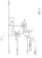
- FIG. 1is a block diagram of one embodiment of a battery charger in accordance with the present invention.
- FIG. 2is a schematic diagram of a portion of the battery charger shown in FIG. 1 .
- FIG. 3is a schematic diagram of one embodiment of a battery controller.
- FIG. 4is a schematic diagram of another embodiment of a battery controller.
- FIG. 1illustrates a block diagram of one embodiment of a battery charger.
- the battery chargerincludes a source selector 100 , a current sensor 102 and a battery controller 104 .
- the source selector 100selectively couples either a primary power source (P 1 ) or a secondary power source (P 2 ) to a system power terminal (V-LOAD).
- the system power terminalprovides a load current to a system load 108 .
- the voltage at the system power terminalis a relatively low DC voltage (e.g., 5 volts DC) and the system load 108 is a portable electronic device (e.g., a USB device).
- the secondary power sourcee.g., a USB power interface or port
- the secondary power sourcecan supply a limited amount of current and an optional current limiter 112 is inserted between the secondary power source and an input to the source selector 100 to clamp the supply current from the secondary power source at a predetermined level.
- the current sensor 102is coupled in series between the secondary power source and the system power terminal to measure current supplied by the secondary power source.
- the current sensor 102can be placed before or after the source selector 100 .
- the current sensor 102is placed between an output of the source selector 100 and the system power terminal.
- the current sensor 102outputs a sense signal (e.g., a current or a voltage) indicative of the supply current from the secondary power source.
- the sense signal (I-SENSE)is provided to the battery controller 104 .
- the battery controller 104is coupled between the system power terminal and a battery 110 .
- the battery 110is a rechargeable (or an internal) battery that supplies current to the system load 108 when the primary power source and the secondary power source do not supply sufficient current to the system load 108 .
- the battery 110can be charged or recharged by either of the power sources when the electronic device 108 is inactive or when the load current is less than a predefined (e.g., a maximum) current capability of the active power source.
- the battery controller (or charging circuit) 104controls a charging current supplied to the battery 110 by one of the power sources and a discharging current supplied by the battery 110 to the system load 108 using a bi-directional device.
- the battery controller 104linearly adjusts (or regulates) the charging current and may limit the charging current to ensure that the supply current from the secondary power source is less than a predefined level.
- the charging currentmay be scaled back when the system load 108 demands more power to allow the combination of the charging current and the load current to be less than the predefined level.
- the ability to linearly control the charging currentensures that the battery controller 104 can utilize a desired portion or substantially all of the available power to charge the battery 110 .
- the available charging currentadvantageously decreases as the load current increases, and the available charging current advantageously increases as the load current decreases.
- a logic interface circuit 106accepts inputs from one or more control lines and generates control signals for the source selector 100 and the battery controller 104 .
- the control linescan receive information from a user input, a computer system, a controller for the electronic device (or system load) 108 , or sensors to generate the appropriate control signals.
- a sensordetects for availability of power from one of the power sources and causes the logic interface circuit 106 to output one or more source enable signals to the source selector 100 to couple the available power source to the system power terminal.
- an AC detection logic signalis optionally available to the logic interface circuit 106 to indicate when power from an AC adapter is available.
- the logic interface circuit 106outputs a plurality of control signals to the battery controller 104 .
- the logic interface circuit 106outputs a controller enable signal to configure the mode of operation for the battery controller 104 .
- the controller enable signalcauses the battery controller 104 to be in a shutdown (or sleep) mode which disconnects the battery 110 from the system power terminal.
- the controller enable signalconfigures the battery controller 104 for normal operations with a battery control loop determining whether the battery controller 104 is in a charge mode or a discharge mode.
- the logic interface circuit 106also outputs a discharge command to force the battery controller 104 into the discharge mode and a limit selector to select a desired reference level for limiting the charging current. Further details of the battery controller 104 will be described below.
- FIG. 2is a schematic diagram of a portion of the battery charger shown in FIG. 1 .
- An AC adapter 228e.g., a primary power source
- a USB power interface 230e.g., a secondary power source
- the AC adapter 228translates (e.g., by transformation, rectification and filtering) an AC voltage into a relatively low DC voltage for the first input.
- the USB power interface 230receives DC power from a computer system via a USB cable for the second input.
- the source selector 224includes at least two isolation circuits (e.g., isolation diodes) 200 , 202 .
- the first isolation diode 200is coupled between the first input and a system power terminal (V-LOAD).
- V-LOADsystem power terminal
- an anode of the first isolation diode 200is coupled to the first input and a cathode of the first isolation diode 200 is coupled to the system power terminal.
- the second isolation diode 202is coupled between the second input and an intermediate node.
- the second isolation diode 202has an anode coupled to the second input and a cathode coupled to the intermediate node.
- the intermediate nodecan be connected directly to the system power terminal.
- a series-connected sensing resistor 220couples the intermediate node to the system power terminal.
- Power from either the AC adapter 228 or the USB power interface 230can be provided to the system power terminal via the respective isolation diodes 200 , 202 .
- An electronic devicee.g., a USB compatible device
- powermay be provided to a rechargeable battery which is also coupled to the system power terminal.
- the first input and the second input of the source selector 224are diode OR-ed so that when only one power source is present, that power source will be able to power the electronic device and to charge the battery.
- the OR-ing diodes (or isolation diodes) 200 , 202block current flow in a reverse direction from the system power terminal to the shorted input.
- bypass transistors 204 , 206are coupled across the respective isolation diodes 200 , 202 to reduce the voltage drops across the isolation diodes 200 , 202 when the isolation diodes 200 , 202 are conducting.
- the bypass transistors 204 , 206can be selectively activated to provide low impedance paths between the respective inputs of the source selector 224 to the system power terminal.
- the bypass transistors 204 , 206facilitate lower input voltage ranges for powering the electronic device and charging the battery. When the battery is in a discharge mode, the bypass transistors 204 , 206 are turned off to prevent battery current from flowing to the power sources.
- the bypass transistors 204 , 206are P-channel MOSFETs with source terminals coupled to the respective cathodes of the isolation diodes 200 , 202 and drain terminals coupled to the respective anodes of the isolation diodes 200 , 202 .
- the bypass transistors 204 , 206can be turned on or off by applying control logic to the respective gate terminals of the bypass transistors 204 , 206 .
- the gate voltage of the first bypass transistor 204is pulled up to logic high by a first pull-up resistor 210 coupled between the gate terminal of the first bypass transistor 204 and the system power terminal. If the first bypass transistor 204 is a P-type transistor, the logic high effectively turns off the first bypass transistor 204 .
- a first pull-down transistor (or N-channel switch) 208controlled by an AC-enable signal, is coupled between the gate terminal of the first bypass transistor 204 and ground.
- the first pull-down transistor 208has a drain terminal coupled to the gate terminal of the first bypass transistor 204 , a source terminal coupled to ground, and a gate terminal coupled to the AC-enable signal. When the AC-enable signal is activated (or logic high), the first pull-down transistor 208 overrides the first pull-up resistor 210 and pulls the gate terminal of the first bypass transistor 204 to logic low, effectively turning on the first bypass transistor 204 .
- the second bypass transistor 206has a second pull-up resistor 216 and a second pull-down transistor 212 to control its on/off states.
- the second pull-up resistor 216is coupled between the system power terminal and a drain terminal of the second pull-down transistor 212 .
- the second pull-down transistor 212has a source terminal coupled to ground and a gate terminal controlled by a USB-enable signal.
- the drain terminal of the second pull-down transistor 212is coupled to the gate terminal of the second bypass transistor 206 via a series-connected current-limiting resistor 214 .
- the current-limiting resistor 214advantageously allows for an overriding circuit (e.g., an override diode) 218 to be coupled between the first input of the source selector 224 and the gate terminal of the second bypass transistor 206 .
- Powermay be available from both the AC adapter 228 and the USB power interface 230 at the same time.
- the override diode 218automatically turns off the second bypass transistor 206 when power is available from the AC adapter 228 , overriding any control by the second pull-down transistor 212 or the second pull-up resistor 216 . Turning off the second bypass transistor 206 effectively isolations the USB power interface 230 from the system power terminal when the AC adapter 228 is active.
- the power available from the USB power interface 230is limited.
- the USB power interface 230may have a maximum current rating of 100 mA or 500 mA at 5 volts.
- a current sensor 226monitors current from the USB power interface 230 to ensure compliance with the maximum current rating.
- the current sensor 226includes the current sensing resistor 220 and a sense circuit 222 .
- the sensing resistor 220is coupled between the second isolation diode 202 and the system power terminal to sense the current from the USB power interface 230 .
- the sense circuit 222is coupled across the sensing resistor 220 and generates a sense signal (I-SENSE) indicative of the current level from the USB power interface 230 .
- the sense signalcan be a voltage or a current which is provided to the battery controller 104 for comparison with a reference corresponding to the predetermined (or a maximum) current capability of the particular USB power interface 230 . Base on the comparison, the battery controller 104 determines the amount of excess power available to charge the battery and still remain in compliance with the USB standard or any other specification.
- FIG. 3is a schematic diagram of one embodiment of a battery controller 320 .
- the battery controller 320includes a bi-directional device (or a pass element) 300 coupled between a system power terminal (V-LOAD) and a battery terminal (V-BATTERY).
- the bi-directional device 300conducts a charging current in a first direction from the system power terminal to the battery terminal to charge a battery coupled to the battery terminal.
- the bi-directional device 300also conducts a discharging current in a second (or opposite) direction from the battery terminal to the system power terminal to provide power to a system load coupled to the system power terminal.
- the bi-directional device 300advantageously isolates the battery from the system load during charging of the battery and provides a relatively low-impedance path from the battery to the system load during discharging of the battery.
- the bi-directional device 300allows for regulation of the charging current, the discharging current, or both.
- the bi-directional device 300is a FET, such as a P-channel MOSFET shown in FIG. 3 .
- the P-channel MOSFET 300has a source terminal coupled to the system power terminal and a drain terminal coupled to the battery terminal.
- the voltage at a gate terminal of the P-channel MOSFET 300can be varied to control (or regulate) the current flow through the P-channel MOSFET 300 .
- a battery control loop 304controls the various operating modes of the bi-directional device 300 .
- the battery control loop 304determines whether to operate the bi-directional device 300 in a charge mode to charge the battery, a discharge mode to provide battery power to the system load, or a disabled mode to disconnect the battery from the system load.
- the battery control loop 304can also determine the charging or discharging current levels. The operating modes and the current levels may be dictated by a system controller (not shown).
- the battery control loop 304includes two inputs coupled to the system power terminal and the battery terminal respectively to automatically sense or determine the operating mode. For example, when the system power terminal is greater than the battery terminal by a first predefined amount, the battery controller 320 operates in the charge mode. When the system power terminal is less than the battery terminal by a second predefined amount, the battery controller 320 operates in the discharge mode.
- the battery control loop 304has a third input coupled to the gate terminal of the bi-directional device 300 .
- the battery control loop 304detects a voltage difference between the system power terminal and the battery terminal.
- the battery control loop 304outputs a feedback control signal based on the voltage difference and the voltage at the gate terminal of the bi-directional device 300 .
- the feedback control signaldetermines the direction and level of current conducted by the bi-directional device 300 .
- the feedback control signalis provided to a pass element driver 302 , which controls the conduction state of the bi-directional device 300 .
- a pass element driver 302controls the conduction state of the bi-directional device 300 .
- an output of the pass element driver 302is coupled to the gate terminal of the bi-directional device 300 .
- the pass element driver 302can vary the voltage at the gate terminal linearly to regulate or limit the charging current or the discharging current through the bi-directional device 300 .
- varying the voltage at the gate terminaldesirably varies the impedance across the source-drain terminals of the bi-directional device 300 .
- the impedancevaries inversely with the level of discharge current. The impedance is advantageously higher for low discharge currents to maintain a sufficient reverse voltage across the source-drain terminals to provide hysteresis in changing operating modes.
- the battery controller 320is capable of receiving power from a USB port.
- the USB porthas limited power.
- the charging current conducted by the bi-directional device 300may be limited so as not to demand power in excess of what the USB port can provide.
- a current sensormonitors the supply current from the USB port as described above.
- An output of the current sensor(I-SENSE) is provided to an input terminal of an error amplifier 306 .
- the error amplifier 306compares the output of the current sensor with a selected reference level corresponding to a maximum (or a desired) current rating. For example, a first reference level (REF 1 ) corresponds to a 100 mA supply current limit and a second reference level (REF 2 ) corresponds to a 500 mA supply current limit.
- a logic signal(LIMIT SELECTOR) can control a switch 312 to choose which reference level to use based on a particular specification of the USB port.
- An output of the error amplifier 306is provided to the pass element driver 302 . If the output of the current sensor indicates that the supply current exceeds the selected limit, the output of the error amplifier 306 overrides (or dominates) the output of the battery control loop 304 to decrease or suppress the charging current through the bi-directional device 300 .
- the charging currentvaries as a load current to the system load changes so that the total current to both the system load and the battery at any given time does not exceed a predefined (or a maximum) rating when power is provided by the USB port.
- the output of the error amplifier 306is wire OR-ed with the output of the battery control loop 304 .
- a diode 308is coupled between the output of the battery control loop 304 and an input of the pass element driver 302 .
- a diode 310is coupled between the output of the error amplifier 306 and the input of the pass element driver 302 .
- the diodes 308 , 310have commonly connected anodes coupled to the same input of the pass element driver 302 .
- the diodes 308 , 310have cathodes coupled to the output of the battery control loop 304 and the output of the error amplifier 306 respectively.
- the discharge modeis enabled by an external discharge control signal (DISCHARGE).
- DISCHARGEexternal discharge control signal
- the bi-directional device 300turns off to isolate the battery from the system load when the voltage at the battery terminal is greater than the voltage at the system power terminal.
- the bi-directional deviceconducts a discharging current from the battery to the system load when the voltage at the battery terminal is greater than the voltage at the system power terminal.
- the battery control loop 304controls the impedance of the bi-directional device 300 to limit the discharging current to a desired level.
- FIG. 4is a schematic diagram of another embodiment of a battery controller 420 .
- Portions (e.g., the pass element driver 302 , the battery control loop 304 , the error amplifier 306 ) of the battery controller 420 illustrated in FIG. 4is substantially similar to corresponding portions of the battery controller 320 illustrated in FIG. 3 . Details of the similar portions will not be discussed further.
- the battery controller 420 of FIG. 4illustrates a configurable body MOSFET 400 as a bi-directional device for conducting a charging current from a power source to a battery or a discharging current from the battery to a system load.
- the configurable body MOSFET 400has source-drain terminals coupled to a system power terminal and a battery terminal respectively.
- the configurable body MOSFET 400is a P-channel MOSFET with a floating body connection such that either side of the channel can be wired as a source terminal.
- a configurable body contactcan be coupled to the system power terminal (V-LOAD) by a first switch 402 to define the source terminal as connected to the system power terminal for the P-channel MOSFET 400 .
- the configurable body contactcan also be coupled to the battery terminal (V-BATTERY) by a second switch 404 to define the source terminal as connected to the battery terminal for the P-channel MOSFET 400 .
- the configurable body contactis coupled to the system power terminal during a battery charge mode and coupled to the battery terminal during a battery discharge mode.
- a comparator 406senses which side of the P-channel MOSFET 400 is a higher voltage and connects the body to that side of the channel to define the source terminal. For example, a positive input terminal of the comparator 406 is coupled to the system power interface. A negative input terminal of the comparator 406 is coupled to the battery terminal.
- An output of the comparator 406controls the first switch 402 to configure the terminal of the P-channel MOSFET 400 connected to the system power terminal as the source in the battery charge mode (e.g., when the voltage of the system power terminal is greater than the voltage of the battery terminal).
- the P-channel MOSFET 400functions as a linear regulator pass element and varying the degree of enhancement (or gate voltage) of the P-channel MOSFET 400 regulates a charging current to the battery.
- the output of the comparator 406is provided to an inverter 408 , and an output of the inverter 408 controls the second switch 404 .
- the second switch 404operates in an opposite phase to the first switch 404 .
- the second switch 404configures the terminal of the P-channel MOSFET 400 connected to the battery terminal as the source in the battery discharge mode (e.g., when the voltage of the battery terminal is greater than the voltage of the system power terminal).
- the P-channel MOSFET 400regulates a discharging current from the battery or can become a fully enhanced switch to allow current to flow unrestricted in reverse direction to the system load.
- the output of the inverter 408is used to qualify a discharge command (DISCHARGE) and to engage the battery control loop 304 to commence a battery discharge mode.
- DISCHARGEa discharge command
- the output of the inverter 408is provided to a first input of a NAND logic gate 412 .
- the discharge commandis provided to a second input of the NAND logic gate 412 .
- An output of the NAND logic gate 412is provided to the battery control loop 304 .
- the battery control loop 304engages the pass element driver 302 and places the P-channel MOSFET 400 in the discharge mode if the discharge command is active.
- the configurable body contactallows a body diode of the P-channel MOSFET 400 to be connected to the battery terminal through the second switch 404 , thereby allowing the pass element driver 302 to turn off the P-channel MOSFET 400 during a shutdown or disable mode to fully disconnect the battery from the system power terminal.
- a switching diode 416is coupled across the P-channel MOSFET 400 to improve a transient response by the battery.
- the switching diode 416has an anode coupled to the battery terminal and a cathode coupled to the system power terminal.
- the switching diode 416is a high-speed device that provides a faster switchover transient response when the battery provides power to the system load.
- the switching diode 416is inactive during the battery charge mode.
Landscapes
- Engineering & Computer Science (AREA)
- Power Engineering (AREA)
- Charge And Discharge Circuits For Batteries Or The Like (AREA)
Abstract
Description
Claims (17)
Priority Applications (2)
| Application Number | Priority Date | Filing Date | Title |
|---|---|---|---|
| US10/760,126US7525291B1 (en) | 2003-01-21 | 2004-01-16 | Linearly regulated battery charger |
| US12/430,426US7759906B2 (en) | 2003-01-21 | 2009-04-27 | Linearly regulated battery charger |
Applications Claiming Priority (2)
| Application Number | Priority Date | Filing Date | Title |
|---|---|---|---|
| US44171503P | 2003-01-21 | 2003-01-21 | |
| US10/760,126US7525291B1 (en) | 2003-01-21 | 2004-01-16 | Linearly regulated battery charger |
Related Child Applications (1)
| Application Number | Title | Priority Date | Filing Date |
|---|---|---|---|
| US12/430,426DivisionUS7759906B2 (en) | 2003-01-21 | 2009-04-27 | Linearly regulated battery charger |
Publications (1)
| Publication Number | Publication Date |
|---|---|
| US7525291B1true US7525291B1 (en) | 2009-04-28 |
Family
ID=40568914
Family Applications (5)
| Application Number | Title | Priority Date | Filing Date |
|---|---|---|---|
| US10/758,952Expired - LifetimeUS7528582B1 (en) | 2003-01-21 | 2004-01-16 | Battery charging and discharging by using a bi-directional transistor |
| US10/760,126Expired - LifetimeUS7525291B1 (en) | 2003-01-21 | 2004-01-16 | Linearly regulated battery charger |
| US12/430,426Expired - LifetimeUS7759906B2 (en) | 2003-01-21 | 2009-04-27 | Linearly regulated battery charger |
| US12/434,416Expired - Fee RelatedUS7759907B2 (en) | 2003-01-21 | 2009-05-01 | Battery charging and discharging by using a bi-directional transistor |
| US12/838,254Expired - LifetimeUS8193779B2 (en) | 2003-01-21 | 2010-07-16 | Battery charging and discharging by using a bi-directional transistor |
Family Applications Before (1)
| Application Number | Title | Priority Date | Filing Date |
|---|---|---|---|
| US10/758,952Expired - LifetimeUS7528582B1 (en) | 2003-01-21 | 2004-01-16 | Battery charging and discharging by using a bi-directional transistor |
Family Applications After (3)
| Application Number | Title | Priority Date | Filing Date |
|---|---|---|---|
| US12/430,426Expired - LifetimeUS7759906B2 (en) | 2003-01-21 | 2009-04-27 | Linearly regulated battery charger |
| US12/434,416Expired - Fee RelatedUS7759907B2 (en) | 2003-01-21 | 2009-05-01 | Battery charging and discharging by using a bi-directional transistor |
| US12/838,254Expired - LifetimeUS8193779B2 (en) | 2003-01-21 | 2010-07-16 | Battery charging and discharging by using a bi-directional transistor |
Country Status (1)
| Country | Link |
|---|---|
| US (5) | US7528582B1 (en) |
Cited By (32)
| Publication number | Priority date | Publication date | Assignee | Title |
|---|---|---|---|---|
| US20070204178A1 (en)* | 2006-02-24 | 2007-08-30 | Nec Electronics Corporation | Power supply selection/detection circuit |
| US20070210757A1 (en)* | 2006-03-10 | 2007-09-13 | Gunnar Gangstoe | Deep under voltage recovery in a battery pack |
| US20080212249A1 (en)* | 2005-06-10 | 2008-09-04 | Agere Systems Inc. | Multi-Threshold Charging of a Rechargeable Battery |
| US20080218100A1 (en)* | 2005-06-10 | 2008-09-11 | Agere Systems Inc. | Regulation of Electrical Current Through a Resistive Load |
| US20100013441A1 (en)* | 2008-07-15 | 2010-01-21 | Hu Peng | Temperature controller |
| US20110095615A1 (en)* | 2009-10-23 | 2011-04-28 | Hong Fu Jin Precision Industry (Shenzhen) Co., Ltd. | Power source selection circuit and electronic device using the same |
| US20120281356A1 (en)* | 2011-05-06 | 2012-11-08 | Brewer Wesley G | Cases for tablet computers and methods |
| WO2013038286A1 (en)* | 2011-09-13 | 2013-03-21 | Koninklijke Philips Electronics N.V. | Battery charging with dynamic current limiting cross-reference to related applications |
| WO2013093002A1 (en)* | 2011-12-21 | 2013-06-27 | Universität Rostock | Voltage supply for mobile devices |
| US8758031B2 (en) | 2012-04-19 | 2014-06-24 | Pass & Seymour, Inc. | Electrical wiring device with high current USB charging capabilities |
| US20150253830A1 (en)* | 2014-03-10 | 2015-09-10 | Dell Products L.P. | Method for Adapter Over-Current-Protection (OCP) Protection and User Warning |
| US20150323979A1 (en)* | 2014-05-06 | 2015-11-12 | Microchip Technology Incorporated | Usb power port control |
| US20160028270A1 (en)* | 2012-05-24 | 2016-01-28 | Associated Equipment Corporation | Charge control for external manual battery chargers |
| US9351025B1 (en)* | 2015-04-17 | 2016-05-24 | Rovi Guides, Inc. | Systems and methods for providing automatic content recognition to verify affiliate programming |
| US9368982B2 (en) | 2013-07-31 | 2016-06-14 | Leviton Manufacturing Co., Inc. | Wiring device having a housing with multiple portions and low voltage ports |
| EP3043443A1 (en)* | 2015-01-08 | 2016-07-13 | Hand Held Products, Inc. | Charge limit selection for variable power supply configuration |
| US9515419B2 (en)* | 2013-08-14 | 2016-12-06 | Mathew Inskeep | High power rechargeable flashlight with two way universal serial BUS |
| US20170093154A1 (en)* | 2015-09-28 | 2017-03-30 | Nxp B.V. | Bus interfaces with unpowered termination |
| US20180006482A1 (en)* | 2016-07-03 | 2018-01-04 | Samsung Electronics Co., Ltd. | Terminal apparatus, input apparatus, and power controlling method thereof |
| US20180115237A1 (en)* | 2015-03-11 | 2018-04-26 | Telcodium Inc. | Power supply connecting board with variable output voltage levels |
| CN108877719A (en)* | 2018-07-25 | 2018-11-23 | 惠科股份有限公司 | power supply device and display device |
| CN110048474A (en)* | 2018-01-17 | 2019-07-23 | 瑞萨电子美国有限公司 | Autonomous adaptation device direct mode operation for buck battery charger |
| US10605418B2 (en) | 2018-07-26 | 2020-03-31 | E. Mishan & Sons, Inc. | Rechargeable flashlight |
| US10958087B2 (en)* | 2018-07-21 | 2021-03-23 | Orest Fedan | Battery protection system |
| US11034255B2 (en) | 2016-10-30 | 2021-06-15 | Chakratec Ltd. | System and method for a station providing grid support |
| US20220181898A1 (en)* | 2020-12-07 | 2022-06-09 | Texas Instruments Incorporated | Integrated Battery Charge Regulation Circuit Based on Power FET Conductivity Modulation |
| US11780345B2 (en) | 2009-07-23 | 2023-10-10 | Chargepoint, Inc. | Managing electric current allocation between charging equipment for charging electric vehicles |
| US11813959B2 (en) | 2016-05-25 | 2023-11-14 | Chargepoint, Inc. | Dynamic allocation of power modules for charging electric vehicles |
| US11951863B2 (en)* | 2009-12-17 | 2024-04-09 | Chargepoint, Inc. | Method and apparatus for management of current load to an electric vehicle charging station in a residence |
| US12074464B2 (en) | 2018-09-18 | 2024-08-27 | Leviton Manufacturing Co., Inc. | Systems and methods for Universal Serial Bus (USB) power delivery with multiple charging ports |
| US12119701B2 (en) | 2018-09-18 | 2024-10-15 | Leviton Manufacturing Co., Inc. | Systems and methods for universal serial bus (USB) power delivery with multiple charging ports |
| US12157387B2 (en) | 2016-03-23 | 2024-12-03 | Chargepoint, Inc. | Dynamic allocation of power modules for charging electric vehicles |
Families Citing this family (66)
| Publication number | Priority date | Publication date | Assignee | Title |
|---|---|---|---|---|
| EP1960048B1 (en) | 2005-12-07 | 2010-08-04 | Boston Scientific Neuromodulation Corporation | Battery protection and zero-volt battery recovery system for an implantable medical device |
| US8080905B2 (en)* | 2007-02-27 | 2011-12-20 | Delta Systems, Inc. | Control system |
| CN101281417B (en)* | 2007-04-06 | 2011-11-09 | 鸿富锦精密工业(深圳)有限公司 | Power supply switching device |
| KR101494900B1 (en)* | 2007-07-25 | 2015-02-24 | 삼성전자주식회사 | A portable terminal having a charging function through charging device identification and a method |
| JP5189343B2 (en)* | 2007-10-23 | 2013-04-24 | ローム株式会社 | Selector circuit and electronic device using the same |
| CN101884153A (en)* | 2007-12-03 | 2010-11-10 | 罗姆股份有限公司 | Power management circuit |
| US8358107B2 (en)* | 2007-12-31 | 2013-01-22 | Intel Corporation | Bidirectional power management techniques |
| US7843171B2 (en)* | 2008-01-21 | 2010-11-30 | Semtech Corporation | Method and apparatus for battery charging based on battery capacity and charging source constraints |
| US20100133908A1 (en)* | 2008-11-28 | 2010-06-03 | Lite-On It Corp. | Usb device with internal assisting power |
| WO2011014595A2 (en) | 2009-07-31 | 2011-02-03 | Thermo King Corporation | Bi-directional battery voltage converter |
| JP5628022B2 (en)* | 2009-12-28 | 2014-11-19 | パナソニック株式会社 | Electronic device and power supply control method |
| TW201210200A (en)* | 2010-08-24 | 2012-03-01 | Hon Hai Prec Ind Co Ltd | Power booster and electronic system using same |
| JP2012050208A (en)* | 2010-08-25 | 2012-03-08 | Canon Inc | Power supply circuit and equipment incorporating the same |
| JP2012060762A (en)* | 2010-09-08 | 2012-03-22 | Seiko Instruments Inc | Charge and discharge control circuit, and battery device |
| JP5706648B2 (en)* | 2010-09-08 | 2015-04-22 | セイコーインスツル株式会社 | Charge / discharge control circuit and battery device |
| JP5706649B2 (en)* | 2010-09-08 | 2015-04-22 | セイコーインスツル株式会社 | Charge / discharge control circuit and battery device |
| KR101922034B1 (en)* | 2010-10-15 | 2018-11-26 | 페어차일드 세미컨덕터 코포레이션 | Power management with over voltage protection |
| JP5348697B2 (en)* | 2010-10-22 | 2013-11-20 | Necアクセステクニカ株式会社 | Power path switching method and power path switching circuit |
| CN102570520A (en)* | 2010-12-22 | 2012-07-11 | 深圳富泰宏精密工业有限公司 | Charging circuit and charging method thereof |
| TW201232239A (en)* | 2011-01-24 | 2012-08-01 | Asmedia Technology Inc | Method and controller allocating charging ports |
| CN102611148A (en)* | 2011-01-24 | 2012-07-25 | 祥硕科技股份有限公司 | Method and controller for configuring charging port |
| US8884589B2 (en)* | 2011-09-14 | 2014-11-11 | Standard Microsystems Corporation | Method and system for power switch temperature regulation |
| US8692520B2 (en)* | 2011-09-15 | 2014-04-08 | Standard Microsystems Corporation | Method and system for optimizing current limiting behavior of charger |
| CN103036274B (en)* | 2011-10-06 | 2016-03-16 | 英特赛尔美国有限公司 | There is the battery charge modulator of boost capability |
| TWI554001B (en)* | 2011-10-06 | 2016-10-11 | 英特希爾美國公司 | Controller and method for controlling switching converter of power stage,electronic device, and controller for battery charge modulator |
| US9246348B2 (en)* | 2011-10-06 | 2016-01-26 | Intersil Americas Llc. | Battery charge modulator with boost capability |
| JP5941656B2 (en)* | 2011-10-28 | 2016-06-29 | ローム株式会社 | Charging circuit and electronic device using the same |
| US8542064B2 (en) | 2011-10-31 | 2013-09-24 | Hewlett-Packard Development Company, L.P. | Methods and apparatus to control power in a printer |
| US9166434B2 (en)* | 2012-06-29 | 2015-10-20 | Intel Corporation | Universal charger |
| KR101458766B1 (en)* | 2012-12-06 | 2014-11-07 | 알파 앤드 오메가 세미컨덕터, 인코포레이티드 | An input line selector system for battery chargers |
| US9287702B2 (en) | 2012-12-27 | 2016-03-15 | Intel Corporation | Universal power interface |
| US9281699B2 (en) | 2012-12-27 | 2016-03-08 | Intel Corporation | Electronic device to be powered by alternative power source |
| US9184627B2 (en) | 2012-12-28 | 2015-11-10 | Intel Corporation | Charging system for electronic device |
| KR102091508B1 (en) | 2013-04-23 | 2020-03-20 | 삼성전자주식회사 | Power supply circuit and method for controlling thereof |
| KR102121856B1 (en)* | 2013-09-03 | 2020-06-11 | 삼성전자주식회사 | Charge controlling apparatus and method for the same |
| EP2944010B1 (en)* | 2013-12-26 | 2019-04-17 | MediaTek Inc. | Multipath charger and charging method thereof |
| US9345883B2 (en) | 2014-02-14 | 2016-05-24 | Boston Scientific Neuromodulation Corporation | Rechargeable-battery implantable medical device having a primary battery active during a rechargeable-battery undervoltage condition |
| CN103840530B (en)* | 2014-03-20 | 2016-06-08 | 成都市智合微电子有限公司 | The single-chip intelligent power that the multichannel independence current limliting of bringing onto load state-detection exports |
| US9601938B2 (en) | 2014-05-15 | 2017-03-21 | Intel Corporation | Battery charger for different power sources |
| CN104348225B (en)* | 2014-08-12 | 2017-07-11 | 矽力杰半导体技术(杭州)有限公司 | A kind of battery charge-discharge circuit of Single switch and the control method of battery charging and discharging |
| CN105446206B (en) | 2014-09-25 | 2019-04-05 | 恩智浦美国有限公司 | Electric power switching control between USB and wireless power system |
| JP6520147B2 (en)* | 2015-01-26 | 2019-05-29 | 富士通クライアントコンピューティング株式会社 | Portable electronic device, charge control circuit and charge control method |
| CN104703343B (en)* | 2015-02-05 | 2017-11-24 | 成都赛昂电子科技有限公司 | A kind of intelligent PWM drive circuit |
| US10565042B2 (en)* | 2015-06-18 | 2020-02-18 | European Space Agency | Bus failure detection transceiver architecture and transceiver operation method |
| US9312701B1 (en)* | 2015-07-16 | 2016-04-12 | Wi-Charge Ltd | System for optical wireless power supply |
| KR102455846B1 (en) | 2016-03-14 | 2022-10-18 | 위-차지 리미티드. | Systems for Optical Wireless Power Supplies |
| US10476287B2 (en)* | 2016-06-30 | 2019-11-12 | Intel IP Corporation | Bi-directional precharge mechanism for charger circuits |
| US10250059B2 (en) | 2016-09-19 | 2019-04-02 | Microsoft Technology Licensing, Llc | Charging circuit for battery-powered device |
| KR102757507B1 (en)* | 2017-02-13 | 2025-01-20 | 삼성전자주식회사 | Reverse voltage monitoring circuit capable of reducing power consumption and Semiconductor device having the same |
| US10997490B2 (en)* | 2017-02-24 | 2021-05-04 | International Business Machines Corporation | Battery-based neural network weights |
| CN106712216B (en)* | 2017-02-28 | 2019-07-26 | 维沃移动通信有限公司 | A charging method and charging system |
| JP6837899B2 (en)* | 2017-04-13 | 2021-03-03 | エイブリック株式会社 | Charge / discharge control circuit and battery device |
| US10228742B2 (en) | 2017-05-18 | 2019-03-12 | Cypress Semiconductor Corporation | USB power control analog subsystem architecture |
| JP6813695B2 (en)* | 2017-05-18 | 2021-01-13 | サイプレス セミコンダクター コーポレーション | Current sensing in USB power controlled analog subsystems |
| US10222402B2 (en) | 2017-05-18 | 2019-03-05 | Cypress Semiconductor Corporation | Current sensing in a USB power control analog subsystem |
| CN107623357B (en)* | 2017-10-23 | 2020-04-10 | 深圳市乐得瑞科技有限公司 | Power supply load capacity evaluation method and USB type converter |
| US10438648B2 (en)* | 2018-01-11 | 2019-10-08 | Micron Technology, Inc. | Apparatuses and methods for maintaining a duty cycle error counter |
| TWI643426B (en)* | 2018-01-17 | 2018-12-01 | 茂達電子股份有限公司 | Fast charging circuit |
| US10630028B2 (en) | 2018-04-12 | 2020-04-21 | Cypress Semiconductor Corporation | Reverse overcurrent protection for universal serial bus type-C (USB-C) connector systems |
| US10320180B1 (en) | 2018-04-24 | 2019-06-11 | Cypress Semiconductor Corporation | Current control and protection for universal serial bus type-C (USB-C) connector systems |
| US10990150B2 (en)* | 2018-07-24 | 2021-04-27 | Texas Instruments Incorporated | VCONN in power delivery chargers |
| CN110854802B (en)* | 2018-08-20 | 2022-06-28 | 纬联电子科技(中山)有限公司 | Overcurrent protection circuit and method thereof |
| CN110442220B (en)* | 2019-06-24 | 2023-03-24 | 深圳市绿联科技股份有限公司 | Power supply control device and method for USB-C interface equipment |
| US20220252677A1 (en)* | 2021-02-11 | 2022-08-11 | EV Power WA Pty Ltd | Battery management system |
| US20230117407A1 (en)* | 2021-10-19 | 2023-04-20 | Chargepoint, Inc. | Dynamic allocation of power modules for charging electric vehicles |
| US12272976B1 (en)* | 2024-05-03 | 2025-04-08 | Geotab Inc. | Device and method for supplying electric power from a primary electronic device to a secondary electronic device |
Citations (38)
| Publication number | Priority date | Publication date | Assignee | Title |
|---|---|---|---|---|
| US4901217A (en) | 1987-12-01 | 1990-02-13 | Apple Computer, Inc. | Digital input power supply and method |
| US5239495A (en) | 1989-06-23 | 1993-08-24 | Kabushiki Kaisha Toshiba | Power supply control system for a portable computer |
| US5313642A (en) | 1990-10-03 | 1994-05-17 | Seagull Scientific Systems, Inc. | Power interface for peripheral devices |
| US5349282A (en) | 1990-12-11 | 1994-09-20 | Span, Inc. | Battery charging and monitoring system |
| US5465039A (en) | 1992-09-16 | 1995-11-07 | International Business Machines Corporation | Power supply for electronic device, and electronic device system |
| US5621299A (en)* | 1994-01-27 | 1997-04-15 | David A. Krall | Rechargeable battery power supply with load voltage sensing, selectable output voltage and a wrist rest |
| US5625275A (en) | 1995-05-24 | 1997-04-29 | Ast Research, Inc. | Power supply which provides a variable charging current to a battery in a portable computer system |
| US5729120A (en)* | 1996-12-30 | 1998-03-17 | General Signal Corporation | Dynamic voltage regulation stabilization for AC power supply systems |
| US5739596A (en)* | 1995-04-06 | 1998-04-14 | Seiko Epson Corporation | Power supply for an electronic device and power delivery method therefor |
| US5764028A (en) | 1995-12-15 | 1998-06-09 | Compaq Computer Corporation | Battery pack with single charge-inhibit/regulator transistor |
| US5786682A (en) | 1996-08-07 | 1998-07-28 | Reltec Corporation | Battery charging circuit including a current limiter which compares a reference current to a charging current to ensure operation of a load |
| US5884086A (en) | 1997-04-15 | 1999-03-16 | International Business Machines Corporation | System and method for voltage switching to supply various voltages and power levels to a peripheral device |
| US5903137A (en) | 1995-12-15 | 1999-05-11 | Compaq Computer Corporation | Battery pack with single charge inhibit/regulator transistor |
| US5978236A (en)* | 1997-01-31 | 1999-11-02 | Silverline Power Conversion Llc | Uninterruptible power supply with direction of DC electrical energy depending on predetermined ratio |
| US5982160A (en) | 1998-12-24 | 1999-11-09 | Harris Corporation | DC-to-DC converter with inductor current sensing and related methods |
| US5986437A (en) | 1996-12-17 | 1999-11-16 | Samsung Electronics Co., Ltd. | Power supply system for portable electronic devices |
| US6000042A (en) | 1997-08-25 | 1999-12-07 | 3Com Corporation | Fault detection on a dual supply system for a universal serial bus system |
| US6058034A (en) | 1998-10-19 | 2000-05-02 | Dell Usa Lp | Current converter and source identification and detection |
| US6114842A (en) | 1999-10-26 | 2000-09-05 | Kaiser Systems, Inc. | Precision voltage regulator for capacitor-charging power supply |
| US6130813A (en) | 1999-01-11 | 2000-10-10 | Dell U.S.A., L.P. | Protection circuit for electronic devices |
| US6133712A (en) | 1998-08-21 | 2000-10-17 | Fairchild Korea Semiconductor Ltd. | Battery charge controller having an adjustable termination current |
| US6147682A (en) | 1996-05-07 | 2000-11-14 | Samsung Electronics, Ltd. | Monitor for use with computer system and method of controlling supply of power to computer peripherals connected with the monitor |
| US6169384B1 (en) | 1999-04-19 | 2001-01-02 | Packard Bell Nec Inc. | Power source system for portable electronic devices |
| US6184652B1 (en) | 2000-03-14 | 2001-02-06 | Wen-Chin Yang | Mobile phone battery charge with USB interface |
| US6211649B1 (en) | 1999-03-25 | 2001-04-03 | Sourcenext Corporation | USB cable and method for charging battery of external apparatus by using USB cable |
| US6222347B1 (en) | 1998-04-30 | 2001-04-24 | Apple Computer, Inc. | System for charging portable computer's battery using both the dynamically determined power available based on power consumed by sub-system devices and power limits from the battery |
| US6246214B1 (en)* | 2000-05-10 | 2001-06-12 | Motorola, Inc. | Multiple use of a single transistor for linear regulation charge control and protection of a rechargeable battery |
| US6255800B1 (en) | 2000-01-03 | 2001-07-03 | Texas Instruments Incorporated | Bluetooth enabled mobile device charging cradle and system |
| US20010021659A1 (en) | 2000-03-08 | 2001-09-13 | Nec Corporation | Method and system for connecting a mobile communication unit to a personal computer |
| US20010045813A1 (en) | 2000-04-14 | 2001-11-29 | Fumio Suzuki | Charging apparatus, charging method, charging system, and recording medium onto which is recorded a charging method |
| US6337557B1 (en) | 1999-01-25 | 2002-01-08 | Barry K. Kates | External universal battery charging apparatus and method |
| US20020005707A1 (en) | 2000-05-26 | 2002-01-17 | Kanji Kerai | Battery charging |
| US20020021164A1 (en)* | 2000-08-21 | 2002-02-21 | Fugate Kevin R. | Eliminating power-down popping in audio power amplifiers |
| US20020038432A1 (en) | 2000-09-27 | 2002-03-28 | Acer Communications And Multimedia Inc. | Automatic charging device via a universal serial bus and method of operating the same |
| US20020061739A1 (en) | 2000-11-17 | 2002-05-23 | Fujitsu Takamisawa Component Limited | Wireless mouse unit, wireless mouse and receiver |
| US6418075B2 (en)* | 2000-07-21 | 2002-07-09 | Mitsubishi Denki Kabushiki Kaisha | Semiconductor merged logic and memory capable of preventing an increase in an abnormal current during power-up |
| US20020130638A1 (en) | 2001-03-19 | 2002-09-19 | Sherman Leonard Harris | Universal serial bus powered battery charger |
| US6465987B1 (en) | 2000-10-17 | 2002-10-15 | Hewlett-Packard Company | Power source of peripheral devices |
Family Cites Families (2)
| Publication number | Priority date | Publication date | Assignee | Title |
|---|---|---|---|---|
| CA2517333C (en)* | 2001-03-01 | 2007-11-27 | Research In Motion Limited | System and method for powering and charging a mobile communication device |
| US6861824B1 (en)* | 2002-07-10 | 2005-03-01 | Arquesttechnology, Inc. | Charger system with dual-level current regulation and dual-level thermal regulation |
- 2004
- 2004-01-16USUS10/758,952patent/US7528582B1/ennot_activeExpired - Lifetime
- 2004-01-16USUS10/760,126patent/US7525291B1/ennot_activeExpired - Lifetime
- 2009
- 2009-04-27USUS12/430,426patent/US7759906B2/ennot_activeExpired - Lifetime
- 2009-05-01USUS12/434,416patent/US7759907B2/ennot_activeExpired - Fee Related
- 2010
- 2010-07-16USUS12/838,254patent/US8193779B2/ennot_activeExpired - Lifetime
Patent Citations (40)
| Publication number | Priority date | Publication date | Assignee | Title |
|---|---|---|---|---|
| US4901217A (en) | 1987-12-01 | 1990-02-13 | Apple Computer, Inc. | Digital input power supply and method |
| US5239495A (en) | 1989-06-23 | 1993-08-24 | Kabushiki Kaisha Toshiba | Power supply control system for a portable computer |
| US5313642A (en) | 1990-10-03 | 1994-05-17 | Seagull Scientific Systems, Inc. | Power interface for peripheral devices |
| US5514859A (en) | 1990-10-03 | 1996-05-07 | Seagull Scientific Systems, Inc. | Power and data interface for peripheral devices |
| US5349282A (en) | 1990-12-11 | 1994-09-20 | Span, Inc. | Battery charging and monitoring system |
| US5465039A (en) | 1992-09-16 | 1995-11-07 | International Business Machines Corporation | Power supply for electronic device, and electronic device system |
| US5621299A (en)* | 1994-01-27 | 1997-04-15 | David A. Krall | Rechargeable battery power supply with load voltage sensing, selectable output voltage and a wrist rest |
| US5739596A (en)* | 1995-04-06 | 1998-04-14 | Seiko Epson Corporation | Power supply for an electronic device and power delivery method therefor |
| US5625275A (en) | 1995-05-24 | 1997-04-29 | Ast Research, Inc. | Power supply which provides a variable charging current to a battery in a portable computer system |
| US5764028A (en) | 1995-12-15 | 1998-06-09 | Compaq Computer Corporation | Battery pack with single charge-inhibit/regulator transistor |
| US5903137A (en) | 1995-12-15 | 1999-05-11 | Compaq Computer Corporation | Battery pack with single charge inhibit/regulator transistor |
| US6147682A (en) | 1996-05-07 | 2000-11-14 | Samsung Electronics, Ltd. | Monitor for use with computer system and method of controlling supply of power to computer peripherals connected with the monitor |
| US5786682A (en) | 1996-08-07 | 1998-07-28 | Reltec Corporation | Battery charging circuit including a current limiter which compares a reference current to a charging current to ensure operation of a load |
| US5986437A (en) | 1996-12-17 | 1999-11-16 | Samsung Electronics Co., Ltd. | Power supply system for portable electronic devices |
| US5729120A (en)* | 1996-12-30 | 1998-03-17 | General Signal Corporation | Dynamic voltage regulation stabilization for AC power supply systems |
| US5978236A (en)* | 1997-01-31 | 1999-11-02 | Silverline Power Conversion Llc | Uninterruptible power supply with direction of DC electrical energy depending on predetermined ratio |
| US5884086A (en) | 1997-04-15 | 1999-03-16 | International Business Machines Corporation | System and method for voltage switching to supply various voltages and power levels to a peripheral device |
| US6170062B1 (en)* | 1997-08-25 | 2001-01-02 | 3Com Corporation | Fault detection on dual supply system for a universal serial bus system |
| US6000042A (en) | 1997-08-25 | 1999-12-07 | 3Com Corporation | Fault detection on a dual supply system for a universal serial bus system |
| US6222347B1 (en) | 1998-04-30 | 2001-04-24 | Apple Computer, Inc. | System for charging portable computer's battery using both the dynamically determined power available based on power consumed by sub-system devices and power limits from the battery |
| US6133712A (en) | 1998-08-21 | 2000-10-17 | Fairchild Korea Semiconductor Ltd. | Battery charge controller having an adjustable termination current |
| US6058034A (en) | 1998-10-19 | 2000-05-02 | Dell Usa Lp | Current converter and source identification and detection |
| US5982160A (en) | 1998-12-24 | 1999-11-09 | Harris Corporation | DC-to-DC converter with inductor current sensing and related methods |
| US6130813A (en) | 1999-01-11 | 2000-10-10 | Dell U.S.A., L.P. | Protection circuit for electronic devices |
| US6337557B1 (en) | 1999-01-25 | 2002-01-08 | Barry K. Kates | External universal battery charging apparatus and method |
| US6211649B1 (en) | 1999-03-25 | 2001-04-03 | Sourcenext Corporation | USB cable and method for charging battery of external apparatus by using USB cable |
| US6169384B1 (en) | 1999-04-19 | 2001-01-02 | Packard Bell Nec Inc. | Power source system for portable electronic devices |
| US6114842A (en) | 1999-10-26 | 2000-09-05 | Kaiser Systems, Inc. | Precision voltage regulator for capacitor-charging power supply |
| US6255800B1 (en) | 2000-01-03 | 2001-07-03 | Texas Instruments Incorporated | Bluetooth enabled mobile device charging cradle and system |
| US20010021659A1 (en) | 2000-03-08 | 2001-09-13 | Nec Corporation | Method and system for connecting a mobile communication unit to a personal computer |
| US6184652B1 (en) | 2000-03-14 | 2001-02-06 | Wen-Chin Yang | Mobile phone battery charge with USB interface |
| US20010045813A1 (en) | 2000-04-14 | 2001-11-29 | Fumio Suzuki | Charging apparatus, charging method, charging system, and recording medium onto which is recorded a charging method |
| US6246214B1 (en)* | 2000-05-10 | 2001-06-12 | Motorola, Inc. | Multiple use of a single transistor for linear regulation charge control and protection of a rechargeable battery |
| US20020005707A1 (en) | 2000-05-26 | 2002-01-17 | Kanji Kerai | Battery charging |
| US6418075B2 (en)* | 2000-07-21 | 2002-07-09 | Mitsubishi Denki Kabushiki Kaisha | Semiconductor merged logic and memory capable of preventing an increase in an abnormal current during power-up |
| US20020021164A1 (en)* | 2000-08-21 | 2002-02-21 | Fugate Kevin R. | Eliminating power-down popping in audio power amplifiers |
| US20020038432A1 (en) | 2000-09-27 | 2002-03-28 | Acer Communications And Multimedia Inc. | Automatic charging device via a universal serial bus and method of operating the same |
| US6465987B1 (en) | 2000-10-17 | 2002-10-15 | Hewlett-Packard Company | Power source of peripheral devices |
| US20020061739A1 (en) | 2000-11-17 | 2002-05-23 | Fujitsu Takamisawa Component Limited | Wireless mouse unit, wireless mouse and receiver |
| US20020130638A1 (en) | 2001-03-19 | 2002-09-19 | Sherman Leonard Harris | Universal serial bus powered battery charger |
Non-Patent Citations (1)
| Title |
|---|
| Bruce R. Ferguson: Copending U.S. Patent Application entitled USB Battery Charger; U.S. Appl. No. 10/758,952, filed Jan. 16, 2004. |
Cited By (59)
| Publication number | Priority date | Publication date | Assignee | Title |
|---|---|---|---|---|
| US7737665B2 (en)* | 2005-06-10 | 2010-06-15 | Agere Systems Inc. | Multi-threshold charging of a rechargeable battery |
| US7830101B2 (en) | 2005-06-10 | 2010-11-09 | Agere Systems, Inc. | Regulation of electrical current through a resistive load |
| US20080212249A1 (en)* | 2005-06-10 | 2008-09-04 | Agere Systems Inc. | Multi-Threshold Charging of a Rechargeable Battery |
| US20080218100A1 (en)* | 2005-06-10 | 2008-09-11 | Agere Systems Inc. | Regulation of Electrical Current Through a Resistive Load |
| US20070204178A1 (en)* | 2006-02-24 | 2007-08-30 | Nec Electronics Corporation | Power supply selection/detection circuit |
| US20130038131A1 (en)* | 2006-02-24 | 2013-02-14 | Renesas Electronics Corporation | Semiconductor device to select a power supply |
| US8063514B2 (en)* | 2006-02-24 | 2011-11-22 | Renesas Electronics Corporation | Power supply selection/detection circuit |
| US8330294B2 (en) | 2006-02-24 | 2012-12-11 | Renesas Electronics Corporation | Power supply selection/detection circuit |
| US20070210757A1 (en)* | 2006-03-10 | 2007-09-13 | Gunnar Gangstoe | Deep under voltage recovery in a battery pack |
| US7605568B2 (en)* | 2006-03-10 | 2009-10-20 | Atmel Corporation | Deep under voltage recovery in a battery pack |
| US20100013441A1 (en)* | 2008-07-15 | 2010-01-21 | Hu Peng | Temperature controller |
| US11780345B2 (en) | 2009-07-23 | 2023-10-10 | Chargepoint, Inc. | Managing electric current allocation between charging equipment for charging electric vehicles |
| US20110095615A1 (en)* | 2009-10-23 | 2011-04-28 | Hong Fu Jin Precision Industry (Shenzhen) Co., Ltd. | Power source selection circuit and electronic device using the same |
| US11951863B2 (en)* | 2009-12-17 | 2024-04-09 | Chargepoint, Inc. | Method and apparatus for management of current load to an electric vehicle charging station in a residence |
| US20120281356A1 (en)* | 2011-05-06 | 2012-11-08 | Brewer Wesley G | Cases for tablet computers and methods |
| US9158336B2 (en)* | 2011-05-06 | 2015-10-13 | Micron Technology, Inc. | Cases for tablet computers and methods |
| CN103797678A (en)* | 2011-09-13 | 2014-05-14 | 皇家飞利浦有限公司 | Battery charging with dynamic current limiting |
| US9948124B2 (en) | 2011-09-13 | 2018-04-17 | Koninklijke Philips N.V. | Battery charging with dynamic current limiting |
| JP2014530590A (en)* | 2011-09-13 | 2014-11-17 | コーニンクレッカ フィリップス エヌ ヴェ | Battery charging with dynamic current limit |
| WO2013038286A1 (en)* | 2011-09-13 | 2013-03-21 | Koninklijke Philips Electronics N.V. | Battery charging with dynamic current limiting cross-reference to related applications |
| CN103797678B (en)* | 2011-09-13 | 2016-10-26 | 皇家飞利浦有限公司 | Battery Charging with Dynamic Current Limiting |
| WO2013093002A1 (en)* | 2011-12-21 | 2013-06-27 | Universität Rostock | Voltage supply for mobile devices |
| US8758031B2 (en) | 2012-04-19 | 2014-06-24 | Pass & Seymour, Inc. | Electrical wiring device with high current USB charging capabilities |
| US20160028270A1 (en)* | 2012-05-24 | 2016-01-28 | Associated Equipment Corporation | Charge control for external manual battery chargers |
| US9991736B2 (en)* | 2012-05-24 | 2018-06-05 | Associated Equipment Corporation | Charge control for external manual battery chargers |
| US9368982B2 (en) | 2013-07-31 | 2016-06-14 | Leviton Manufacturing Co., Inc. | Wiring device having a housing with multiple portions and low voltage ports |
| US9515419B2 (en)* | 2013-08-14 | 2016-12-06 | Mathew Inskeep | High power rechargeable flashlight with two way universal serial BUS |
| US20150253830A1 (en)* | 2014-03-10 | 2015-09-10 | Dell Products L.P. | Method for Adapter Over-Current-Protection (OCP) Protection and User Warning |
| US10355505B2 (en)* | 2014-03-10 | 2019-07-16 | Dell Products L.P. | Method for adapter over-current-protection (OCP) protection and user warning |
| US20150323979A1 (en)* | 2014-05-06 | 2015-11-12 | Microchip Technology Incorporated | Usb power port control |
| US9715271B2 (en)* | 2014-05-06 | 2017-07-25 | Microchip Technology Incorporated | USB power port control |
| EP3043443A1 (en)* | 2015-01-08 | 2016-07-13 | Hand Held Products, Inc. | Charge limit selection for variable power supply configuration |
| US20180115237A1 (en)* | 2015-03-11 | 2018-04-26 | Telcodium Inc. | Power supply connecting board with variable output voltage levels |
| US10879787B2 (en)* | 2015-03-11 | 2020-12-29 | Telcodium Inc. | Power supply connecting board with variable output voltage levels |
| US9351025B1 (en)* | 2015-04-17 | 2016-05-24 | Rovi Guides, Inc. | Systems and methods for providing automatic content recognition to verify affiliate programming |
| US20170093154A1 (en)* | 2015-09-28 | 2017-03-30 | Nxp B.V. | Bus interfaces with unpowered termination |
| CN106557445B (en)* | 2015-09-28 | 2021-06-08 | 恩智浦有限公司 | Bus interface with unpowered end |
| CN106557445A (en)* | 2015-09-28 | 2017-04-05 | 恩智浦有限公司 | EBI with non-feeder ear |
| US10003192B2 (en)* | 2015-09-28 | 2018-06-19 | Nxp B.V. | Bus interfaces with unpowered termination |
| US12157387B2 (en) | 2016-03-23 | 2024-12-03 | Chargepoint, Inc. | Dynamic allocation of power modules for charging electric vehicles |
| US12221010B2 (en) | 2016-05-25 | 2025-02-11 | Chargepoint, Inc. | Dynamic allocation of power modules for charging electric vehicles |
| US11958380B2 (en) | 2016-05-25 | 2024-04-16 | Chargepoint, Inc. | Dynamic allocation of power modules for charging electric vehicles |
| US11813959B2 (en) | 2016-05-25 | 2023-11-14 | Chargepoint, Inc. | Dynamic allocation of power modules for charging electric vehicles |
| US20180006482A1 (en)* | 2016-07-03 | 2018-01-04 | Samsung Electronics Co., Ltd. | Terminal apparatus, input apparatus, and power controlling method thereof |
| US11034255B2 (en) | 2016-10-30 | 2021-06-15 | Chakratec Ltd. | System and method for a station providing grid support |
| US11400826B2 (en) | 2016-10-30 | 2022-08-02 | Zooz Power Ltd | System and method for a station providing grid support |
| US11691528B2 (en) | 2016-10-30 | 2023-07-04 | Zooz Power Ltd | System and method for plug-in vehicle to plug-in vehicle charging |
| US11205915B2 (en)* | 2018-01-17 | 2021-12-21 | Renesas Electronics America | Autonomous adapter pass through mode for buck-boost battery charger |
| CN110048474A (en)* | 2018-01-17 | 2019-07-23 | 瑞萨电子美国有限公司 | Autonomous adaptation device direct mode operation for buck battery charger |
| TWI782173B (en)* | 2018-01-17 | 2022-11-01 | 美商瑞薩電子美國有限公司 | Autonomous adapter pass through mode for buck-boost battery charger |
| US10958087B2 (en)* | 2018-07-21 | 2021-03-23 | Orest Fedan | Battery protection system |
| US11303119B2 (en) | 2018-07-25 | 2022-04-12 | HKC Corporation Limited | Power supply device and display device |
| CN108877719A (en)* | 2018-07-25 | 2018-11-23 | 惠科股份有限公司 | power supply device and display device |
| CN108877719B (en)* | 2018-07-25 | 2021-01-05 | 惠科股份有限公司 | Power supply device and display device |
| US10605418B2 (en) | 2018-07-26 | 2020-03-31 | E. Mishan & Sons, Inc. | Rechargeable flashlight |
| US12074464B2 (en) | 2018-09-18 | 2024-08-27 | Leviton Manufacturing Co., Inc. | Systems and methods for Universal Serial Bus (USB) power delivery with multiple charging ports |
| US12119701B2 (en) | 2018-09-18 | 2024-10-15 | Leviton Manufacturing Co., Inc. | Systems and methods for universal serial bus (USB) power delivery with multiple charging ports |
| US20220181898A1 (en)* | 2020-12-07 | 2022-06-09 | Texas Instruments Incorporated | Integrated Battery Charge Regulation Circuit Based on Power FET Conductivity Modulation |
| US11916426B2 (en)* | 2020-12-07 | 2024-02-27 | Texas Instruments Incorporated | Integrated battery charge regulation circuit based on power FET conductivity modulation |
Also Published As
| Publication number | Publication date |
|---|---|
| US8193779B2 (en) | 2012-06-05 |
| US20090206794A1 (en) | 2009-08-20 |
| US7528582B1 (en) | 2009-05-05 |
| US20090212741A1 (en) | 2009-08-27 |
| US7759906B2 (en) | 2010-07-20 |
| US20100277125A1 (en) | 2010-11-04 |
| US7759907B2 (en) | 2010-07-20 |
Similar Documents
| Publication | Publication Date | Title |
|---|---|---|
| US7525291B1 (en) | Linearly regulated battery charger | |
| US11646569B2 (en) | Secondary battery protection circuit, secondary battery protection apparatus and battery pack | |
| US9866016B2 (en) | Multiport power converter with load detection capabilities | |
| AU2004213885B2 (en) | Circuit and method of operation for an electrical power supply | |
| KR101041730B1 (en) | Voltage converter with combined capacitive voltage divider, buck converter and battery charger | |
| KR101060052B1 (en) | Voltage converter with combined buck converter and capacitive voltage divider | |
| KR101445011B1 (en) | Power converter with reduced power consumption when toggling between sleep and normal modes during device charging | |
| US7064521B2 (en) | Charging circuit for parallel charging in multiple battery systems | |
| US7141954B2 (en) | Li-ion/Li-polymer battery charger configured to be DC-powered from multiple types of wall adapters | |
| US8203234B2 (en) | Power safety system | |
| CN110138024B (en) | Charging control device, charging system, and charging control method | |
| US20040164708A1 (en) | Circuit and method of operation for an electrical power supply | |
| GB2416605A (en) | Dual power bus for battery powered device | |
| US7793116B2 (en) | Power supply system with remote control circuit and power supply system operation method | |
| US7336005B2 (en) | System and method for brownout protection of a FET based battery switch | |
| CN113614919A (en) | Semiconductor integrated circuit having a plurality of transistors | |
| KR20070092074A (en) | Power Supply and Power Supply Method | |
| JP2005323497A (en) | Power supply unit |
Legal Events
| Date | Code | Title | Description |
|---|---|---|---|
| AS | Assignment | Owner name:MICROSEMI CORPORATION, CALIFORNIA Free format text:ASSIGNMENT OF ASSIGNORS INTEREST;ASSIGNOR:FERGUSON, BRUCE R.;REEL/FRAME:015502/0366 Effective date:20040610 | |
| STCF | Information on status: patent grant | Free format text:PATENTED CASE | |
| AS | Assignment | Owner name:MORGAN STANLEY & CO. INCORPORATED, NEW YORK Free format text:PATENT SECURITY AGREEMENT;ASSIGNORS:WHITE ELECTRONIC DESIGNS CORP.;ACTEL CORPORATION;MICROSEMI CORPORATION;REEL/FRAME:025783/0613 Effective date:20110111 | |
| FPAY | Fee payment | Year of fee payment:4 | |
| FEPP | Fee payment procedure | Free format text:PAYOR NUMBER ASSIGNED (ORIGINAL EVENT CODE: ASPN); ENTITY STATUS OF PATENT OWNER: LARGE ENTITY | |
| AS | Assignment | Owner name:BANK OF AMERICA, N.A., AS SUCCESSOR AGENT, NORTH C Free format text:NOTICE OF SUCCESSION OF AGENCY;ASSIGNOR:ROYAL BANK OF CANADA (AS SUCCESSOR TO MORGAN STANLEY & CO. LLC);REEL/FRAME:035657/0223 Effective date:20150402 | |
| AS | Assignment | Owner name:MICROSEMI COMMUNICATIONS, INC. (F/K/A VITESSE SEMI Free format text:RELEASE BY SECURED PARTY;ASSIGNOR:BANK OF AMERICA, N.A.;REEL/FRAME:037558/0711 Effective date:20160115 Owner name:MICROSEMI CORPORATION, CALIFORNIA Free format text:RELEASE BY SECURED PARTY;ASSIGNOR:BANK OF AMERICA, N.A.;REEL/FRAME:037558/0711 Effective date:20160115 Owner name:MICROSEMI CORP.-ANALOG MIXED SIGNAL GROUP, A DELAW Free format text:RELEASE BY SECURED PARTY;ASSIGNOR:BANK OF AMERICA, N.A.;REEL/FRAME:037558/0711 Effective date:20160115 Owner name:MICROSEMI SOC CORP., A CALIFORNIA CORPORATION, CAL Free format text:RELEASE BY SECURED PARTY;ASSIGNOR:BANK OF AMERICA, N.A.;REEL/FRAME:037558/0711 Effective date:20160115 Owner name:MICROSEMI SEMICONDUCTOR (U.S.) INC., A DELAWARE CO Free format text:RELEASE BY SECURED PARTY;ASSIGNOR:BANK OF AMERICA, N.A.;REEL/FRAME:037558/0711 Effective date:20160115 Owner name:MICROSEMI CORP.-MEMORY AND STORAGE SOLUTIONS (F/K/ Free format text:RELEASE BY SECURED PARTY;ASSIGNOR:BANK OF AMERICA, N.A.;REEL/FRAME:037558/0711 Effective date:20160115 Owner name:MICROSEMI FREQUENCY AND TIME CORPORATION, A DELAWA Free format text:RELEASE BY SECURED PARTY;ASSIGNOR:BANK OF AMERICA, N.A.;REEL/FRAME:037558/0711 Effective date:20160115 | |
| AS | Assignment | Owner name:MORGAN STANLEY SENIOR FUNDING, INC., NEW YORK Free format text:PATENT SECURITY AGREEMENT;ASSIGNORS:MICROSEMI CORPORATION;MICROSEMI SEMICONDUCTOR (U.S.) INC. (F/K/A LEGERITY, INC., ZARLINK SEMICONDUCTOR (V.N.) INC., CENTELLAX, INC., AND ZARLINK SEMICONDUCTOR (U.S.) INC.);MICROSEMI FREQUENCY AND TIME CORPORATION (F/K/A SYMMETRICON, INC.);AND OTHERS;REEL/FRAME:037691/0697 Effective date:20160115 | |
| FPAY | Fee payment | Year of fee payment:8 | |
| AS | Assignment | Owner name:IP GEM GROUP, LLC, CALIFORNIA Free format text:ASSIGNMENT OF ASSIGNORS INTEREST;ASSIGNOR:MICROSEMI CORPORATION;REEL/FRAME:043137/0792 Effective date:20170721 | |
| AS | Assignment | Owner name:MICROSEMI CORP. - RF INTEGRATED SOLUTIONS, CALIFOR Free format text:RELEASE BY SECURED PARTY;ASSIGNOR:MORGAN STANLEY SENIOR FUNDING, INC.;REEL/FRAME:046251/0391 Effective date:20180529 Owner name:MICROSEMI COMMUNICATIONS, INC., CALIFORNIA Free format text:RELEASE BY SECURED PARTY;ASSIGNOR:MORGAN STANLEY SENIOR FUNDING, INC.;REEL/FRAME:046251/0391 Effective date:20180529 Owner name:MICROSEMI CORP. - POWER PRODUCTS GROUP, CALIFORNIA Free format text:RELEASE BY SECURED PARTY;ASSIGNOR:MORGAN STANLEY SENIOR FUNDING, INC.;REEL/FRAME:046251/0391 Effective date:20180529 Owner name:MICROSEMI SOC CORP., CALIFORNIA Free format text:RELEASE BY SECURED PARTY;ASSIGNOR:MORGAN STANLEY SENIOR FUNDING, INC.;REEL/FRAME:046251/0391 Effective date:20180529 Owner name:MICROSEMI CORPORATION, CALIFORNIA Free format text:RELEASE BY SECURED PARTY;ASSIGNOR:MORGAN STANLEY SENIOR FUNDING, INC.;REEL/FRAME:046251/0391 Effective date:20180529 Owner name:MICROSEMI SEMICONDUCTOR (U.S.), INC., CALIFORNIA Free format text:RELEASE BY SECURED PARTY;ASSIGNOR:MORGAN STANLEY SENIOR FUNDING, INC.;REEL/FRAME:046251/0391 Effective date:20180529 Owner name:MICROSEMI FREQUENCY AND TIME CORPORATION, CALIFORN Free format text:RELEASE BY SECURED PARTY;ASSIGNOR:MORGAN STANLEY SENIOR FUNDING, INC.;REEL/FRAME:046251/0391 Effective date:20180529 | |
| MAFP | Maintenance fee payment | Free format text:PAYMENT OF MAINTENANCE FEE, 12TH YEAR, LARGE ENTITY (ORIGINAL EVENT CODE: M1553); ENTITY STATUS OF PATENT OWNER: LARGE ENTITY Year of fee payment:12 |