US7525283B2 - Contact-less power transfer - Google Patents
Contact-less power transferDownload PDFInfo
- Publication number
- US7525283B2 US7525283B2US10/514,046US51404605AUS7525283B2US 7525283 B2US7525283 B2US 7525283B2US 51404605 AUS51404605 AUS 51404605AUS 7525283 B2US7525283 B2US 7525283B2
- Authority
- US
- United States
- Prior art keywords
- primary unit
- conductive elements
- secondary device
- power transfer
- area
- Prior art date
- Legal status (The legal status is an assumption and is not a legal conclusion. Google has not performed a legal analysis and makes no representation as to the accuracy of the status listed.)
- Active, expires
Links
Images


Classifications
- H—ELECTRICITY
- H01—ELECTRIC ELEMENTS
- H01F—MAGNETS; INDUCTANCES; TRANSFORMERS; SELECTION OF MATERIALS FOR THEIR MAGNETIC PROPERTIES
- H01F3/00—Cores, Yokes, or armatures
- H01F3/02—Cores, Yokes, or armatures made from sheets
- H—ELECTRICITY
- H01—ELECTRIC ELEMENTS
- H01F—MAGNETS; INDUCTANCES; TRANSFORMERS; SELECTION OF MATERIALS FOR THEIR MAGNETIC PROPERTIES
- H01F27/00—Details of transformers or inductances, in general
- H01F27/24—Magnetic cores
- H01F27/25—Magnetic cores made from strips or ribbons
- H—ELECTRICITY
- H01—ELECTRIC ELEMENTS
- H01F—MAGNETS; INDUCTANCES; TRANSFORMERS; SELECTION OF MATERIALS FOR THEIR MAGNETIC PROPERTIES
- H01F27/00—Details of transformers or inductances, in general
- H01F27/28—Coils; Windings; Conductive connections
- H01F27/2804—Printed windings
- H—ELECTRICITY
- H01—ELECTRIC ELEMENTS
- H01F—MAGNETS; INDUCTANCES; TRANSFORMERS; SELECTION OF MATERIALS FOR THEIR MAGNETIC PROPERTIES
- H01F38/00—Adaptations of transformers or inductances for specific applications or functions
- H01F38/14—Inductive couplings
- H—ELECTRICITY
- H01—ELECTRIC ELEMENTS
- H01F—MAGNETS; INDUCTANCES; TRANSFORMERS; SELECTION OF MATERIALS FOR THEIR MAGNETIC PROPERTIES
- H01F41/00—Apparatus or processes specially adapted for manufacturing or assembling magnets, inductances or transformers; Apparatus or processes specially adapted for manufacturing materials characterised by their magnetic properties
- H01F41/02—Apparatus or processes specially adapted for manufacturing or assembling magnets, inductances or transformers; Apparatus or processes specially adapted for manufacturing materials characterised by their magnetic properties for manufacturing cores, coils, or magnets
- H01F41/0206—Manufacturing of magnetic cores by mechanical means
- H01F41/0213—Manufacturing of magnetic circuits made from strip(s) or ribbon(s)
- H01F41/0226—Manufacturing of magnetic circuits made from strip(s) or ribbon(s) from amorphous ribbons
- H—ELECTRICITY
- H01—ELECTRIC ELEMENTS
- H01F—MAGNETS; INDUCTANCES; TRANSFORMERS; SELECTION OF MATERIALS FOR THEIR MAGNETIC PROPERTIES
- H01F41/00—Apparatus or processes specially adapted for manufacturing or assembling magnets, inductances or transformers; Apparatus or processes specially adapted for manufacturing materials characterised by their magnetic properties
- H01F41/02—Apparatus or processes specially adapted for manufacturing or assembling magnets, inductances or transformers; Apparatus or processes specially adapted for manufacturing materials characterised by their magnetic properties for manufacturing cores, coils, or magnets
- H01F41/0206—Manufacturing of magnetic cores by mechanical means
- H01F41/0233—Manufacturing of magnetic circuits made from sheets
- H—ELECTRICITY
- H01—ELECTRIC ELEMENTS
- H01F—MAGNETS; INDUCTANCES; TRANSFORMERS; SELECTION OF MATERIALS FOR THEIR MAGNETIC PROPERTIES
- H01F5/00—Coils
- H01F5/003—Printed circuit coils
- H—ELECTRICITY
- H02—GENERATION; CONVERSION OR DISTRIBUTION OF ELECTRIC POWER
- H02J—CIRCUIT ARRANGEMENTS OR SYSTEMS FOR SUPPLYING OR DISTRIBUTING ELECTRIC POWER; SYSTEMS FOR STORING ELECTRIC ENERGY
- H02J50/00—Circuit arrangements or systems for wireless supply or distribution of electric power
- H02J50/10—Circuit arrangements or systems for wireless supply or distribution of electric power using inductive coupling
- H02J50/12—Circuit arrangements or systems for wireless supply or distribution of electric power using inductive coupling of the resonant type
- H—ELECTRICITY
- H02—GENERATION; CONVERSION OR DISTRIBUTION OF ELECTRIC POWER
- H02J—CIRCUIT ARRANGEMENTS OR SYSTEMS FOR SUPPLYING OR DISTRIBUTING ELECTRIC POWER; SYSTEMS FOR STORING ELECTRIC ENERGY
- H02J50/00—Circuit arrangements or systems for wireless supply or distribution of electric power
- H02J50/70—Circuit arrangements or systems for wireless supply or distribution of electric power involving the reduction of electric, magnetic or electromagnetic leakage fields
- H—ELECTRICITY
- H02—GENERATION; CONVERSION OR DISTRIBUTION OF ELECTRIC POWER
- H02J—CIRCUIT ARRANGEMENTS OR SYSTEMS FOR SUPPLYING OR DISTRIBUTING ELECTRIC POWER; SYSTEMS FOR STORING ELECTRIC ENERGY
- H02J7/00—Circuit arrangements for charging or depolarising batteries or for supplying loads from batteries
- H02J7/0042—Circuit arrangements for charging or depolarising batteries or for supplying loads from batteries characterised by the mechanical construction
- H—ELECTRICITY
- H01—ELECTRIC ELEMENTS
- H01F—MAGNETS; INDUCTANCES; TRANSFORMERS; SELECTION OF MATERIALS FOR THEIR MAGNETIC PROPERTIES
- H01F27/00—Details of transformers or inductances, in general
- H01F27/24—Magnetic cores
- H01F27/245—Magnetic cores made from sheets, e.g. grain-oriented
Definitions
- This inventionrelates to a new apparatus and method for transferring power in a contact-less fashion.
- Example devicesinclude cellular telephones, laptop computers, the Palm 500 series of Personal Digital Assistants, electric shavers and electric toothbrushes. In some of these devices, the cells are recharged via inductive coupling rather than direct electrical connection. Examples include the Braun Oral B Plak Control power toothbrush, the Panasonic Digital Cordless Phone Solution KX-PH15AL and the Panasonic multi-head men's shavers ES70/40 series.
- Each of these devicestypically has an adaptor or charger which takes power from mains electricity, a car cigarette lighter or other sources of power and converts it into a form suitable for charging the secondary cells.
- an adaptor or chargerwhich takes power from mains electricity, a car cigarette lighter or other sources of power and converts it into a form suitable for charging the secondary cells.
- Chargers which use inductive chargingremove the need to have open electrical contacts hence allowing the adaptor and device to be sealed and used in wet environments (for example the electric toothbrush as mentioned above is designed to be used in a bathroom).
- the chargersstill suffer from all other problems as described above.
- the devicesstill need to be placed accurately into a charger such that the device and the charger are in a predefined relative position (See FIGS. 1 a and 1 b ).
- the adaptorsare still only designed specifically for a certain make and model of device and are still only capable of charging one device at a time. As a result, users still need to possess and manage a collection of different adaptors.
- Universal chargerssuch as the Maha MH-C777 Plus Universal charger
- these universal chargerseliminate the need for having different chargers for different devices, they create even more inconvenience for the user in the sense that the battery packs first need to be removed, then the charger needs to be adjusted and the battery pack needs to be accurately positioned in or relative to the charger. In addition, time must be spent to determine the correct pair of battery pack metal contacts which the charger must use.
- the primary unitis capable of emitting an electromagnetic field over a large area (See FIG. 2 a ). Users can simply place one or more devices to be recharged within range of the primary unit, with no requirement to place them accurately.
- this primary unitmay consist of a coil encircling a large area. When a current flows through the coil, an electromagnetic field extending over a large area is created and devices can be placed anywhere within this area.
- this methodsuffers from a number of drawbacks. Firstly, the intensity of electromagnetic emissions is governed by regulatory limits.
- this methodcan only support power transfer at a limited rate.
- a secondary devicecomprising a conventional coil (see FIG. 2 a ) is placed against a metallic plate such as a copper plane in a printed circuit board or metallic can of a cell, coupling is likely to be significantly reduced.
- Non-uniform field distributionis also a drawback. When all the coils are activated in the primary unit, they sum to an equivalent of a large coil, the magnetic field distribution of which is seen to exhibit a minimum at the centre of the coil.
- Some portable devicesare capable of receiving power coupled inductively from a recharger, for example the Braun Oral B Plak Control toothbrush.
- a rechargerfor example the Braun Oral B Plak Control toothbrush.
- Such portable devicestypically have a custom, dedicated power-receiving module built-in to the device, which then interfaces with an internal standard cell or battery (which may or may not be removable).
- a system for transferring power without requiring direct electrical conductive contactscomprising:
- a primary unit for transferring power without requiring direct electrical conductive contactsincluding a substantially laminar charging surface and at least one means for generating an electromagnetic field, the means being distributed in two dimensions across a predetermined area in or parallel to the charging surface so as to define at least one charging area of the charging surface that is substantially coextensive with the predetermined area, the charging area having a width and a length on the charging surface, wherein the means is configured such that, when a predetermined current is supplied thereto and the primary unit is effectively in electromagnetic isolation, an electromagnetic field generated by the means has electromagnetic field lines that, when averaged over any quarter length part of the charging area measured parallel to a direction of the field lines, subtend an angle of 45° or less to the charging surface in proximity thereto and are distributed in two dimensions thereover, and wherein the means has a height measured substantially perpendicular to the charging area that is less than either of the width or the length of the charging area.
- a method of transferring power in a non-conductive manner from a primary unit to a secondary deviceincluding a substantially laminar charging surface and at least one means for generating an electromagnetic field, the means being distributed in two dimensions across a predetermined area in or parallel to the charging surface so as to define at least one charging area of the charging surface that is substantially coextensive with the predetermined area, the charging area having a width and a length on the charging surface, the means having a height measured substantially perpendicular to the charging area that is less than either of the width or the length of the charging area, and the secondary device having at least one electrical conductor; wherein:
- a secondary devicefor use with the system, unit or method of the first, second or third aspects, the secondary device including at least one electrical conductor and having a substantially laminar form factor.
- the word “laminar”defines a geometry in the form of a thin sheet or lamina.
- the thin sheet or laminamay be substantially flat, or may be curved.
- the primary unitmay include an integral power supply for the at least one means for generating an electromagnetic field, or may be provided with connectors or the like enabling the at least one means to be connected to an external power supply.
- the means for generating the electromagnetic fieldhave a height that is no more than half the width or half the length of the charging area; in some embodiments, the height may be no more than 1 ⁇ 5 of the width or 1 ⁇ 5 of the length of the charging area.
- the at least one electrical conductor in the secondary devicemay be wound about a core that serves to concentrate flux therein.
- the core(where provided) may offer a path of least resistance to flux lines of the electromagnetic field generated by the primary unit.
- the coremay be amorphous magnetically permeable material. In some embodiments, there is no need for an amorphous core.
- the amorphous magnetic materialis a non-annealed or substantially as-cast state.
- the materialmay be at least 70% non-annealed, or preferably at least 90% non-annealed. This is because annealing tends to make amorphous magnetic materials brittle, which is disadvantageous when contained in a device, such as a mobile phone, which may be subjected to rough treatment, for example by being accidentally dropped.
- the amorphous magnetic materialis provided in the form of a flexible ribbon, which may comprise one or more layers of one or more of the same or different amorphous magnetic materials. Suitable materials include alloys which may contain iron, boron and silicon or other suitable materials.
- the alloyis melted and then cooled so rapidly (“quenched”) that there is no time for it to crystallise as it solidifies, thus leaving the alloy in a glass-like amorphous state.
- Suitable materialsinclude Metglas® 2714A and like materials. Permalloy or mumetal or the like may also be used.
- the core in the secondary deviceis preferably a high magnetic permeability core.
- the relative permeability of this coreis preferably at least 100, even more preferably at least 500, and most preferably at least 1000, with magnitudes of at least 10,000 or 100,000 being particularly advantageous.
- the at least one means for generating an electromagnetic fieldmay be a coil, for example in the form of a length of wire or a printed strip, or may be in the form of a conductive plate of appropriate configuration, or may comprise any appropriate arrangement of conductors.
- a preferred materialis copper, although other conductive materials, generally metals, may be used as appropriate.
- the term “coil”is here intended to encompass any appropriate electrical conductor forming an electrical circuit through which current may flow and thus generate an electromagnetic field. In particular, the “coil” need not be wound about a core or former or the like, but may be a simple or complex loop or equivalent structure.
- the charging area of the primary unitis large enough to accommodate the conductor and/or core of the secondary device in a plurality of orientations thereof.
- the charging areais large enough to accommodate the conductor and/or core of the secondary device in any orientation thereof. In this way, power transfer from the primary unit to the secondary device may be achieved without having to align the conductor and/or core of the secondary device in any particular direction when placing the secondary device on the charging surface of the primary unit.
- the substantially laminar charging surface of the primary unitmay be substantially planar, or may be curved or otherwise configured to fit into a predetermined space, such as a glove compartment of a car dashboard or the like. It is particularly preferred that the means for generating an electromagnetic field does not project or protrude above or beyond the charging surface.
- a key feature of the means for generating an electromagnetic field in the primary unitis that electromagnetic field lines generated by the means, measured when the primary unit is effectively in magnetic isolation (i.e. when no secondary device is present on or in proximity to the charging surface), are distributed in two dimensions over the at least one charging area and subtend an angle of 45° or less to the charging area in proximity thereto (for example, less than the height or width of the charging area) and over any quarter length part of the charging area measured in a direction generally parallel to that of the field lines.
- the measurement of the field lines in this connectionis to be understood as a measurement of the field lines when averaged over the quarter length of the charging area, rather than an instantaneous point measurement.
- the field linessubtend an angle of 30° or less, and in some embodiments are substantially parallel to at least a central part of the charging area in question. This is in stark contrast to prior art systems, where the field lines tend to be substantially perpendicular to a surface of a primary unit.
- the direction of the field linesmay be rotated through a complete or partial circle, in one or both directions. Alternatively, the direction may be caused to “wobble” or fluctuate, or may be switched between two or more directions. In more complex configurations, the direction of the field lines may vary as a Lissajous pattern or the like.
- the field linesmay be substantially parallel to each other over any given charging area, or at least have resolved components in or parallel to the plane of the charging area that are substantially parallel to each other at any given moment in time.
- one means for generating an electromagnetic fieldmay serve to provide a field for more than one charging area; also that more than one means may serve to provide a field for just one charging area In other words, there need not be a one-to-one correspondence of means for generating electromagnetic fields and charging areas.
- the secondary devicemay adopt a substantially flat form factor with a core thickness of 2 mm or less.
- a materialsuch as one or more amorphous metal sheets, it is possible to have core thickness down to 1 mm or less for applications where size and weight is important. See FIG. 7 a.
- the primary unitmay include a pair of conductors having adjacent coplanar windings which have mutually substantially parallel linear sections arranged so as to produce a substantially uniform electromagnetic field extending generally parallel to or subtending an angle of 45° or less to the plane of the windings but substantially at right angles to the parallel sections.
- the windings in this embodimentmay be formed in a generally spiral shape, comprising a series of turns having substantially parallel straight sections.
- the primary unitmay include first and second pairs of conductors which are superimposed in substantially parallel planes with the substantially parallel linear sections of the first pair arranged generally at right angles to the substantially parallel linear sections of the second pair, and further comprising a driving circuit which is arranged to drive them in such a way as to generate a resultant field which rotates in a plane substantially parallel to the planes of the windings.
- a system for transferring power in a contact-less mannerconsisting of:
- the battery or cellmay have a primary axis and be capable of being recharged by an alternating field flowing in the primary axis of the battery or cell, the battery or cell consisting of:
- the proposed inventionis a significant departure from the design of conventional inductive power transfer systems.
- the difference between conventional systems and the proposed systemis best illustrated by looking at their respective magnetic flux line patterns. (See FIGS. 2 a and 4 )
- charging areaused in this patent application may refer to the area of the at least one means for generating a field (e.g. one or more conductors in the form of a coil) or an area formed by a combination of primary conductors where the secondary device can couple flux effectively. Some embodiments of this are shown in FIGS. 6 a to 6 l and 9 c as component 740 .
- a feature of a “charging area”is a distribution of conductors over a significant area of the primary unit configured such that it is possible for the at least one means for generating a field to be driven to achieve an instantaneous net flow of flux in one direction.
- a primary unitmay have more than one charging area.
- One charging areais distinct from another charging area when flux cannot be effectively coupled by the secondary device (such as those shown in FIG. 7 a ) in any rotation at the boundary.
- windings of wire or printed tracks or a plane as shown in FIG. 8 erefers to all conductor configurations which feature a charging area as described above. This includes windings of wire or printed tracks or a plane as shown in FIG. 8 e .
- the conductorsmay be made of copper, gold, alloys or any other appropriate material.
- the present applicationrefers to the rotation of a secondary device in several places. It is to be clarified here that if a secondary device is rotated, the axis of rotation being referred to is the one perpendicular to the plane of the charging area.
- the primary unittypically consists of the following components. (See FIG. 5 )
- the secondary devicetypically consists of the following components, as shown in FIG. 5 .
- one or more secondary devicesare placed on top of the charging surface of the primary unit.
- the fluxflows through the at least one conductor and/or core of the secondary devices present and current is induced.
- the rotational orientation of the secondary devicemay affect the amount of flux coupled.
- the primary unitmay exist in many different forms, for example:
- the primary unitmay be powered from different sources, for example:
- the primary unitmay be small enough such that only one secondary device may be accommodated on the charging surface in a single charging area, or may be large enough to accommodate many secondary devices simultaneously, sometimes in different charging areas.
- the means for generating a field in the primary unitmay be driven at mains frequency (50 Hz or 60 Hz) or at some higher frequency.
- the sensing unit of the primary unitmay sense the presence of secondary devices, the number of secondary devices present and even the presence of other magnetic material which is not part of a secondary device. This information may be used to control the current being delivered to the field generating means of the primary unit.
- the primary unit and/or the secondary devicemay be substantially waterproof or explosion proof.
- the primary unit and/or the secondary devicemay be hermetically sealed to standards such as IP66.
- the primary unitmay incorporate visual indicators (for example, but not limited to, light emitting devices, such as light emitting diodes, electrophosphorescent displays, light emitting polymers, or light reflecting devices, such as liquid crystal displays or MITs electronic paper) to indicate the current state of the primary unit, the presence of secondary devices or the number of secondary devices present or any combination of the above.
- visual indicatorsfor example, but not limited to, light emitting devices, such as light emitting diodes, electrophosphorescent displays, light emitting polymers, or light reflecting devices, such as liquid crystal displays or MITs electronic paper
- FIG. 6illustrate some possibilities for such a primary conductor. Although most of the configurations are in fact coil windings, it is to be appreciated that the same effect can also be achieved with conductor planes which are not typically considered to be coils (See FIG. 6 e ). These drawings are typical examples and are non-exhaustive. These conductors or coils may be used in combination such that the secondary device can couple effectively in all rotations whilst on the charging area(s) of the primary unit.
- the secondary devicemay take a variety of shapes and forms.
- a central axis of the conductorfor example, a coil winding
- FIG. 10A possible system comprising an inductively rechargeable battery or cell and a primary unit is shown in FIG. 10 .
- the batterycan also be rotated along its axis rA while continuing to receive power.
- embodiments of the present inventionare highly advantageous because they can ensure that the battery can receive power while in any random orientation about rA.
- the battery or cellmay include a flux concentrating means that may be arranged in a variety of ways:
- the flux-concentratormay be a functional part of the battery enclosure (for example, an outer zinc electrode) or the battery itself (for example, an inner electrode).
- Issues relating to charging of secondary cellsinclude:
- some sophisticated charge-control means to meter inductive power to the appliance and the cellis advantageously provided. Furthermore, it becomes more important for the primary unit to be able to indicate a “charged” condition, since the secondary cell or battery may not be easily visible when located inside an electrical device.
- a cell or battery enabled in this fashionmay be charged whilst fitted in another device, by placing the device onto the primary unit, or whilst outside the device by placing the cell or battery directly onto the primary unit.
- Batteries enabled in this fashionmay be arranged in packs of cells as in typical devices (e.g. end-to-end or side-by-side), allowing a single pack to replace a set of cells.
- the secondary devicemay consist of a flat “adapter” which fits over the batteries in a device, with thin electrodes which force down between the battery electrodes and the device contacts.
- the secondary deviceswill generally only couple effectively when the windings are placed substantially parallel to the direction of net current flow in the primary conductor as shown by the arrow 1 .
- two coilsfor example one positioned on top of the other or one woven into or otherwise associated with the other, the second coil capable of generating a net current flow substantially perpendicular to the direction of the first coil at any point in the active area of the primary unit.
- These two coilsmay be driven alternately such that each is activated for a certain period of time.
- Another possibilityis to drive the two coils in quadrature such that a rotating magnetic dipole is generated in the plane. This is illustrated in FIG. 9 . This is also possible with other combinations of coil configurations.
- the problem with changing the operating frequencyis that the secondary devices are typically configured to resonate at a predefined frequency. If the operating frequency changes, the secondary device would be detuned. To overcome this problem, it is possible to change the capacitance instead of the operating frequency.
- the secondary devicescan be designed such that each additional device placed in proximity to the primary unit will shift the inductance to a quantised level such that an appropriate capacitor can be switched in to make the circuit resonate at a predetermined frequency. Because of this shift in resonant frequency, the number of devices on the charging surface can be detected and the primary unit can also sense when something is brought near or taken away from the charging surface. If a magnetically permeable object other than a valid secondary device is placed in the vicinity of the charging surface, it is unlikely to shift the system to the predefined quantised level. In such circumstances, the system could automatically detune and reduce the current flowing into the coil.
- FIG. 1shows the magnetic design of typical prior art contact-less power transfer systems which require accurate alignment of the primary unit and secondary device
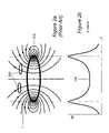
- FIG. 2 ashows the magnetic design of another typical prior art contact-less power transfer system which involves a large coil in the primary unit
- FIG. 2 bshows the non-uniform field distribution inside the large coil at 5 mm distance from the plane of the coil, exhibiting a minimum in the centre;
- FIG. 3shows a multiple-coil system where each coil is independently driven such that a localised field can be generated.
- FIG. 4 ashows an embodiment of the proposed system which demonstrates a substantial departure from prior art with no secondary devices present
- FIG. 4 bshows an embodiment of the proposed system with two secondary devices present
- FIG. 4 cshows a cross section of the active area of the primary unit and the contour lines of the magnetic flux density generated by the conductors.
- FIG. 4 dshows the magnetic circuit for this particular embodiment of the proposed invention
- FIG. 5shows a schematic drawing of an embodiment of the primary unit and the secondary device
- FIG. 6 a to 6 lshow some alternative embodiment designs for the field generating means or a component of the field generating means of the primary unit;
- FIGS. 7 a and 7 bshow some possible designs for the magnetic unit of the secondary device
- FIG. 8shows the effect of flux guides (the thickness of the flux guide has been exaggerated for clarity);
- FIG. 8 ashows that without flux guides, the field tends to fringe into the air directly above the active area
- FIG. 8 bshows the direction of current flow in the conductors in this particular embodiment
- FIG. 8 cshows that the flux is contained within the flux guides when magnetic material is placed on top of the charging area
- FIG. 8 dshows a secondary device on top of the primary unit
- FIG. 8 eshows a cross section of the primary unit without any secondary devices
- FIG. 8 fshows a cross section of the primary unit with a secondary device on top and demonstrates the effect of using a secondary core with higher permeability than the flux guide.
- FIG. 9 ashows a particular coil arrangement with a net instantaneous current flow shown by the direction of the arrow
- FIG. 9 bshows a similar coil arrangement to FIG. 9 a except rotated by 90 degrees
- FIG. 9 cshows the charging area of the primary unit if the coil of FIG. 9 a is placed on top of FIG. 9 b . If the coil in FIG. 9 a is driven in quadrature to FIG. 9 b , the effect is a rotating magnetic dipole shown here;
- FIG. 10shows the case where the secondary device has an axial degree of rotation
- FIG. 11shows various arrangements of secondary devices with axial degrees of rotation
- FIG. 12 a and FIG. 12 bshow another embodiment of the type of coil arrangement shown in FIG. 9 a and FIG. 9 b ;
- FIG. 13shows a simple embodiment of driving unit electronics.
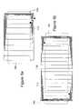
- FIG. 1there is shown two examples of prior art contact-less power transfer systems which both require accurate alignment of a primary unit and a secondary device.
- This embodimentis typically used in electric toothbrush or mobile phone chargers.
- FIG. 1 ashows a primary magnetic unit 100 and a secondary magnetic unit 200 .
- a coil 110is wound around a magnetic core 120 such as ferrite.
- the secondary sideconsists of a coil 210 wound around another magnetic core 220 .
- an alternating currentflows in to the primary coil 110 and generates lines of flux 1 .
- the flux 1will couple from the primary into the secondary, inducing a voltage across the secondary coil 210 .
- FIG. 1 bshows a split transformer.
- the primary magnetic unit 300consists of a U-shaped core 320 with a coil 310 wound around it. When alternating current flows into the primary coil 310 , changing lines of flux are generated 1.
- the secondary magnetic unit 400consists of a second U-shaped core 420 with another coil 410 wound around it. When the secondary magnetic unit 400 is placed on the primary magnetic unit 300 such that the arms of the two U-shaped cores are in alignment, the flux will couple effectively into the core of the secondary 420 and induce voltage across the secondary coil 410 .
- FIG. 2 ais another embodiment of prior art inductive systems typically used in powering radio frequency passive tags.
- the primarytypically consists of a coil 510 covering a large area. Multiple secondary devices 520 will have voltage induced therein when they are within the area encircled by the primary coil 510 . This system does not require the secondary coil 520 to be accurately aligned with the primary coil 510 .
- FIG. 2 bshows a graph of the magnitude of magnetic flux intensity across the area encircled by the primary coil 510 at 5 mm above the plane of the primary coil. It shows a non-uniform field, which exhibits a minimum 530 at the centre of the primary coil 510 .
- FIG. 3is another embodiment of a prior art inductive system wherein a multiple coil array is used.
- the primary magnetic unit 600consists of an array of coils including coils 611 , 612 , 613 .
- the secondary magnetic unit 700may consist of a coil 710 .
- the coils 611 , 612are activated while other coils such as 613 remain inactive.
- the activated coils 611 , 612generate flux, some of which will couple into the secondary magnetic unit 700 .
- FIG. 4shows an embodiment of the proposed invention.
- FIG. 4 ashows a primary coil 710 wound or printed in such a fashion that there is a net instantaneous current flow within the active area 740 .
- a dc currentflows through the primary coil 710
- the conductors in the active area 740would all have current flowing in the same direction.
- Current flowing through the primary coil 710generates flux 1 .
- a layer of magnetic material 730is present beneath the charging area to provide a return path for the flux.
- FIG. 4 bshows the same primary magnetic unit as shown in FIG. 4 a with two secondary devices 800 present. When the secondary devices 800 are placed in the correct orientation on top of the charging area 740 of the primary magnetic unit, the flux 1 will flow through the magnetic core of the secondary devices 800 instead of flowing through the air. The flux 1 flowing through the secondary core would hence induce current in the secondary coil.
- FIG. 4 cshows some contour lines for the flux density of the magnetic field generated by the conductors 711 in the charging area 740 of the primary magnetic unit. There is a layer of magnetic material 730 beneath the conductors to provide a low reluctance return path for the flux.
- FIG. 4 dshows a cross-section of the charging area 740 of the primary magnetic unit. A possible path for the magnetic circuit is shown.
- the magnetic material 730provides a low reluctance path for the circuit and also the magnetic core 820 of the secondary magnetic device 800 also provides a low reluctance path. This minimizes the distance the flux has to travel through the air and hence minimizes leakage.
- FIG. 5shows a schematic drawing of an embodiment of the whole system of the proposed invention.
- the primary unitconsists of a power supply 760 , a control unit 770 , a sensing unit 780 and an electromagnetic unit 700 .
- the power supply 760converts the mains (or other sources of power) into a dc supply at an appropriate voltage for the system.
- the control unit 770controls the driving unit 790 which drives the magnetic unit 700 .
- the magnetic unitconsists of two independently driven components, coil 1 and coil 2 , arranged such that the conductors in the charging area of coil 1 would be perpendicular to the conductors in the charging area of coil 2 .
- the control unitWhen the primary unit is activated, the control unit causes a 90-degree phase shift between the alternating current that flows through coil 1 and coil 2 . This creates a rotating magnetic dipole on the surface of the primary magnetic unit 700 such that a secondary device is able to receive power regardless of its rotational orientation (See FIG. 9 ). In standby mode where no secondary devices are present, the primary unit is detuned and current flow into the magnetic unit 700 is minimised.
- the inductance of the primary magnetic unit 700When a secondary device is placed on top of the charging area of the primary unit, the inductance of the primary magnetic unit 700 is changed. This brings the primary circuit into resonance and the current flow is maximised.
- the inductanceis changed to yet another level and the primary circuit is again detuned.
- the control unit 770uses feedback from the sensing unit 780 to switch another capacitor into the circuit such that it is tuned again and current flow is maximised.
- the secondary devicesare of a standard size and a maximum of six standard-sized devices can receive power from the primary unit simultaneously. Due to the standard sizes of the secondary devices, the change in inductance due to the change in secondary devices in proximity is quantized to a number of predefined levels such that only a maximum of 6 capacitances is required to keep the system operating at resonance.
- FIGS. 6 a to 6 lshow a number of different embodiments for the coil component of the primary magnetic unit. These embodiments may be implemented as the only coil component of the primary magnetic unit, in which case the rotation of the secondary device is important to the power transfer. These embodiments may also be implemented in combination, not excluding embodiments which are not illustrated here. For example, two coils illustrated in FIG. 6 a may be placed at 90 degrees to each other to form a single magnetic unit.
- the charging area 740consists of a series of conductors with net current generally flowing in the same direction.
- FIG. 6 cthere is no substantial linkage when the secondary device is placed directly over the centre of the coil and hence power is not transferred.
- FIG. 6 dthere is no substantial linkage when the secondary device is positioned in the gap between the two charging areas 740 .
- FIG. 6 fshows a specific coil configuration for the primary unit adapted to generate electromagnetic field lines substantially parallel to a surface of the primary unit within the charging area 740 .
- Two primary windings 710are formed about opposing arms of a generally rectangular flux guide 750 made out of a magnetic material, the primary windings 710 generating opposing electromagnetic fields.
- the flux guide 750contains the electromagnetic fields and creates a magnetic dipole across the charging area 740 in the direction of the arrows indicated on the Figure.
- a secondary deviceis placed in the charging area 740 in a predetermined orientation, a low reluctance path is created and flux flows through the secondary device, causing effective coupling and power transfer.
- the flux guide 750need not be continuous, and may in fact be formed as two opposed and non-linked horseshoe components.
- FIG. 6 gshows another possible coil configuration for the primary unit, the coil configuration being adapted to generate electromagnetic field lines substantially parallel to the charging surface of the primary unit within the charging area 740 .
- a primary winding 710is wound around a magnetic core 750 which may be ferrite or some other suitable material.
- the charging area 740includes a series of conductors with instantaneous net current generally flowing in the same direction.
- the coil configuration of FIG. 6 gis in fact capable of supporting or defining a charging area 740 on both upper and lower faces as shown in the drawing, and depending on the design of the primary unit, one or both of the charging areas may be made available to secondary devices.
- FIG. 6 hshows a variation of the configuration of FIG. 6 g .
- the windings 710are not evenly spaced.
- the spacing and variations thereincan be selected or designed so as to provide improved uniformity of performance or field strength levels over the charging area 740 .
- FIG. 6 ishows an embodiment in which two primary windings 710 as shown in FIG. 6 g are located in a mutually orthogonal configuration so as to enable a direction of the field lines to be dynamically switched or rotated to other orientations about the plane of the charging surface.
- FIGS. 6 j and 6 kshow additional two-coil configurations for the primary unit which are not simple geometric shapes with substantially parallel conductors.
- line 710indicates one of a set of current-carrying conductors lying in the plane of the charging surface 600 .
- the shape of the main conductor 710is arbitrary and need not be a regular geometric figure—indeed, conductor 710 may have straight and curved sections and may intersect with itself.
- One or more subsidiary conductors 719are arranged alongside and generally parallel (at any given local point) to the main conductor 710 (only two subsidiary conductors 719 are shown here for clarity). Current flow in subsidiary conductors 719 will be in the same direction as in the main conductor 710 .
- the subsidiary conductors 719may be connected in series or parallel so as to form a single coil arrangement.
- a set of current-carrying conductors 720(only some of which are shown for clarity) is arranged in the plane of the charging surface 600 .
- a main conductor 710is provided as in FIG. 6 j , and the conductors 720 are each arranged so as to be locally orthogonal to the main conductor 710 .
- the conductors 720may be connected in series or parallel so as to form a single coil arrangement.
- a first sinusoidal currentis fed into the conductor 710
- a second sinusoidal current having a 90° phase shift relative to the first currentis fed into the coil 720
- a direction of a resultant electromagnetic field vector at most points on the charging area 740will be seen to rotate through 360°.
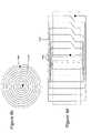
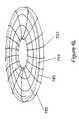
- FIG. 6 lshows yet another alternative arrangement in which the magnetic core 750 is in the shape of a round disc with a hole in the centre.
- the first set of current carrying conductors 710is arranged in a spiral shape on the surface of the round disc.
- the second set of conductors 720is wound in a toroidal format through the centre of the disc and out to the perimeter in a radial fashion.
- These conductorscan be driven in such a way, for example with sinusoidal currents at quadrature, that when a secondary device is placed at any point inside the charging area 740 and rotated about an axis perpendicular to the charging area, no nulls are observed by the secondary device.
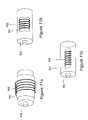
- FIGS. 7 a and 7 bare embodiments of the proposed secondary devices.
- a winding 810is wound around a magnetic core 820 .
- Two of thesemay be combined in a single secondary device, at right angles for example, such that the secondary device is able to effectively couple with the primary unit at all rotations.
- Thesemay also be combined with standard coils, as the ones shown in FIG. 2 a 520 to eliminate dead spots.
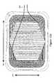
- FIG. 8shows the effect of flux guides 750 positioned on top of the charging area.
- the thickness of the materialhas been exaggerated for the sake of clarity but in reality would be in the order of millimetres thick.
- the flux guides 750will minimize leakage and contain the flux at the expense of reducing the amount of flux coupled to the secondary device.
- FIG. 8 aa primary magnetic unit is shown without flux guides 750 .
- the fieldwill tend to fringe into the air directly above the charging area.
- flux guides 750as shown in FIG. 5 b to 5 f , the flux is contained within the plane of the material and leakage is minimised.
- FIG. 8 ewhen there is no secondary device 800 on top, the flux remains in the flux guide 750 .
- FIG. 8 ewhen there is no secondary device 800 on top, the flux remains in the flux guide 750 .
- the permeability of the flux guide 750can be chosen such that it is higher than that of typical metals such as steel. When other materials such as steel, which are not part of secondary devices 800 , are placed on top, most of the flux will remain in the flux guide 750 instead of travelling through the object.
- the flux guide 750may not be a continuous layer of magnetic material but may have small air gaps in them to encourage more flux flow into the secondary device 800 when it is present.
- FIG. 9shows an embodiment of a primary unit whereby more than one coil is used.
- FIG. 9 ashows a coil 710 with a charging area 740 with current flow parallel to the direction of the arrow 2 .
- FIG. 9 bshows a similar coil arranged at 90 degrees to the one in FIG. 9 a .
- the charging areawill look like the illustration in FIG. 9 c .
- Such an embodimentwould allow the secondary device to be at any rotation on top of the primary unit and couple effectively.
- FIG. 10shows an embodiment where the secondary device has an axial degree of rotation, for example where it is, or is embedded within, a battery cell.
- the secondary devicemay be constructed such that it couples to the primary flux when in any axial rotation (rA) relative to the primary unit ( 910 ), as well as having the same degrees of freedom described above (i.e. translational (X,Y) and optionally rotational perpendicular to the plane of the primary (rZ)).
- FIG. 11 ashows one arrangement where a rechargeable battery cell 930 is wrapped with an optional cylinder of flux-concentrating material 931 which is itself wound with copper wire 932 .
- the cylindermay be long or short relative to the length of the cell.
- FIG. 11 bshows another arrangement where the flux-concentrating material 931 covers only part of the surface of the cell 930 , and has copper wire 932 wrapped around it (but not the cell).
- the material and wiremay be conformed to the surface of the cell. Their area may be large or small relative to the circumference of the cell, and long or short relative to the length of the cell.
- FIG. 11 cshows another arrangement where the flux-concentrating material 931 is embedded within the cell 930 and has copper wire 932 wrapped around it.
- the materialmay be substantially flat, cylindrical, rod-like, or any other shape, its width may be large or small relative to the diameter of the cell, and its length may be large or small relative to the length of the cell.
- any flux-concentrating materialmay also be a functional part of the battery enclosure (for example, an outer zinc electrode) or the battery itself (for example, an inner electrode).
- the powermay be stored in a smaller standard cell (e.g. AAA size) fitted within the larger standard cell enclosure (e.g. AA).
- a smaller standard celle.g. AAA size
- the larger standard cell enclosuree.g. AA
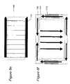
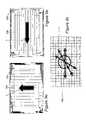
- FIG. 12shows an embodiment of a primary unit similar to that shown in FIG. 9 .
- FIG. 12 ashows a coil generating a field in a direction horizontal to the page
- FIG. 12 bshows another coil generating a field vertical to the page, and the two coils would be mounted in a substantially coplanar fashion, possibly with one above the other, or even intertwined in some fashion.
- the wire connections to each coilare shown 940 and the charging area is represented by the arrows 941 .
- FIG. 13shows a simple embodiment of the Driving Unit ( 790 of FIG. 5 ).
- the PIC processor 960generates two 23.8 kHz square waves 90 degrees out of phase with one another. These are amplified by components 961 and driven into two coil components 962 , which are the same magnetic units shown in FIG. 12 a and FIG. 12 b .
- the driving unitis providing square waves, the high resonant “Q” of the magnetic units shapes this into a sinusoidal waveform.
Landscapes
- Engineering & Computer Science (AREA)
- Power Engineering (AREA)
- Computer Networks & Wireless Communication (AREA)
- Manufacturing & Machinery (AREA)
- Physics & Mathematics (AREA)
- Electromagnetism (AREA)
- Charge And Discharge Circuits For Batteries Or The Like (AREA)
- Soft Magnetic Materials (AREA)
Abstract
Description
- Both the characteristics of the cells within each device and the means of connecting to them vary considerably from manufacturer to manufacturer, and from device to device. Therefore users who own several such devices must also own several different adaptors. If users are going away on travel, they will have to bring their collection of chargers if they expect to use their devices during this time.
- These adaptors and chargers often require users to plug a small connector into the device or to place the device with accurate alignment into a stand causing inconvenience. If users fail to plug or place their device into a charger and it runs out of power, the device becomes useless and important data stored locally in the device might even be lost.
- In addition, most adaptors and chargers have to be plugged into mains sockets and hence if several are used together, they take up space in plug strips and create a messy and confusing tangle of wires.
- Besides the above problems with conventional methods of recharging devices, there are also practical problems associated with devices having an open electrical contact. For example, devices cannot be used in wet environments due to the possibility of corroding or shorting out the contacts and also they cannot be used in flammable gaseous environments due to the possibility of creating electrical sparks.
- Universality: a single primary unit which can supply power to different secondary devices with different power requirements thereby eliminating the need for a collection of different adaptors and chargers;
- Convenience: a single primary unit which allows secondary devices to be placed anywhere within an active vicinity thereby eliminating the need for plugging-in or placing secondary devices accurately relative to an adaptor or charger;
- Multiple-load: a single primary unit that can supply power to a number of secondary different devices with different power requirements at the same time;
- Flexibility for use in different environments: a single primary unit that can supply power to secondary devices such that no direct electrical contact is required thereby allowing for secondary devices and the primary unit itself to be used in wet, gaseous, clean and other atypical environments;
- Low electromagnetic emissions: a primary unit that can deliver power in a manner that will minimize the intensity and size of the magnetic field generated.
- i) a primary unit including a substantially laminar charging surface and at least one means for generating an electromagnetic field, the means being distributed in two dimensions across a predetermined area in or parallel to the charging surface so as to define at least one charging area of the charging surface that is substantially coextensive with the predetermined area, the charging area having a width and a length on the charging surface, wherein the means is configured such that, when a predetermined current is supplied thereto and the primary unit is effectively in electromagnetic isolation, an electromagnetic field generated by the means has electromagnetic field lines that, when averaged over any quarter length part of the charging area measured parallel to a direction of the field lines, subtend an angle of 45° or less to the charging surface in proximity thereto and are distributed in two dimensions thereover, and wherein the means has a height measured substantially perpendicular to the charging area that is less than either of the width or the length of the charging area; and
- ii) at least one secondary device including at least one electrical conductor; wherein, when the at least one secondary device is placed on or in proximity to a charging area of the primary unit, the electromagnetic field lines couple with the at least one conductor of the at least one secondary device and induce a current to flow therein.
- i) an electromagnetic field, generated by the means when energised with a predetermined current and measured when the primary unit is effectively in electromagnetic isolation, has electromagnetic field lines that, when averaged over any quarter length part of the charging area measured parallel to a direction of the field lines, subtend an angle of 45° or less to the charging surface in proximity thereto and are distributed in two dimensions over the at least one charging area when averaged thereover; and
- ii) the electromagnetic field links with the conductor of the secondary device when this is placed on or in proximity to the charging area.
- a primary unit consisting of at least one electrical coil whereby each coil features at least one active area whereby two or more conductors are substantially distributed over this area in such a fashion that it is possible for a secondary device to be placed in proximity to a part of this active area where the net instantaneous current flow in a particular direction is substantially non-zero;
- at least one secondary device consisting of conductors wound around a high permeability core in such a fashion that it is possible for it to be placed in proximity to an area of the surface of the primary unit where the net instantaneous current flow is substantially non-zero;
whereby the at least one secondary device is capable of receiving power by means of electromagnetic induction when the central axis of the winding is in proximity to the active area of the primary unit, is substantially not perpendicular to the plane of the active area of primary unit and is substantially not parallel to the conductors in the active area of at least one of the coils of the primary unit.
- an enclosure and external electrical connections similar in dimensions to industry-standard batteries or cells
- an energy-storage means
- an optional flux-concentrating means
- a power-receiving means
- a means of converting the received power to a form suitable for delivery to outside the cell through the external electrical connections, or to recharge the energy storage means, or both.
- Conventional System: In a conventional system (See
FIG. 2 a), there is typically a planar primary coil which generates a magnetic field with flux lines coming out of the plane in a perpendicular fashion. The secondary device has typically a rotund or square coil that encircles some or all of these flux lines. - Proposed system: In the proposed system, the magnetic field travels substantially horizontally across the surface of the plane (see
FIG. 4 ) instead of directly out of the plane as illustrated inFIG. 2 a. The secondary device hence may have an elongated winding wound around a magnetic core. SeeFIGS. 7 aand7b. When the secondary device is placed on the primary unit, the flux lines would be attracted to travel through the magnetic core of the secondary device because it is the lowest reluctance path. This causes the secondary device and the primary unit to be coupled effectively. The secondary core and winding may be substantially flattened to form a very thin component.
- Conventional System: In a conventional system (See
- No need for accurate alignment: The secondary device can be placed anywhere on a charging area of the primary unit;
- Uniform coupling: In the proposed invention, the coupling between the primary unit and secondary device is much more uniform over the charging area compared to a conventional primary and secondary coil. In a conventional large coil system (see
FIG. 2 a), the field strength dips to a minimum at the centre of the coil, in the plane of the coil (seeFIG. 2 b). This implies that if sufficient power is to be effectively transferred at the centre, the field strength at the minimum has to be above a certain threshold. The field strength at the maximum will then be excessively higher than the required threshold and this may cause undesirable effects. - Universality: a number of different secondary devices, even those having different power requirements, can be placed within charging areas on the charging surface of the primary unit to receive power simultaneously;
- Increased coupling coefficiency: Optional high permeability magnetic material present in the secondary device increases the induced flux significantly by offering a low reluctance path. This can significantly increase the power transfer.
- Desirable form factor for secondary device: The geometry of the system allows thin sheets of magnetic material (such as amorphous metal ribbons) to be used. This means that secondary devices can have the form factor of a thin sheet, making it suitable to be incorporated at the back of mobile phones and other electronic devices. If magnetic material was to be used in the centre of conventional coils, it is likely to increase the bulkiness of the secondary device.
- Minimised field leakage: When one or more secondary devices are present in the charging area of the primary unit, it is possible to use magnetic material in such a way that more than half of the magnetic circuit is low reluctance magnetic material (see
FIG. 4 d). This means that more flux flows for a given magneto-motive force (mmf). As the induced voltage is proportional to the rate of change of flux linked, this will increase the power transfer to the secondary device. The fewer and shorter the air gaps are in the magnetic circuit, the less the field will fringe, the closer the flux is kept to the surface of the primary unit and hence leakage is minimized. - Cost effectiveness: Unlike the multiple-coil design, this solution requires a much simpler control system and fewer components.
- Free axial rotation of secondary device: If the secondary device is thin or optionally even cylindrical (see
FIG. 10 ), it may be constructed such that it continues to couple well to the flux regardless of its rotation about its longest axis. This may in particular be an advantage if the secondary device is a battery cell fitted within another device, when its axial rotation may be difficult to control. - The magnetic core in the secondary device may be located near other parallel planes of metal within or near the device, for example a copper printed circuit board or aluminum cover. In this case, the performance of embodiments of the present invention is significantly better than that of a conventional core-wound coil because the field lines through a conventional device coil will suffer flux-exclusion if the coil is placed up against the metal plane (because the lines of flux must travel perpendicular to the plane of the coil). Since in embodiments of the present invention the lines of flux travel along the plane of the core, and therefore also of the metal plane, performance is improved. An additional benefit is that the magnetic core in a secondary device of embodiments of the present invention can act as a shield between the electromagnetic field generated by the primary unit and any items (e.g. electrical circuits, battery cells) on the other side of the magnetic core.
- Because its permeability is higher than that of air, the magnetic core of the secondary device of embodiments of the present invention acts to concentrate magnetic flux, thus capturing more flux than would otherwise flow through an equivalent cross-section of air. The size of the core's “shape factor” (the equivalent flux-capturing sphere) is determined to a first-order approximation by the longest planar dimension of the core. Therefore if the core of the secondary device of embodiments of the present invention has planar dimensions with a significantly non-square aspect ratio, for example a 4:1 rectangle instead of a 1:1 square, it will capture proportionally more of any flux travelling parallel to the direction of its longest planar dimension. Therefore if used in devices which have a constrained aspect ratio (for example a long thin device such as a headset or pen), a significant increase in performance will be experienced compared with that of a conventional coil of the same area.
- Power supply: This power supply converts mains voltage into a lower voltage dc supply. This is typically a conventional transformer or a switch-mode power supply;
- Control unit: The control unit serves the function of maintaining the resonance of the circuit given that the inductance of the means for generating a field changes with the presence of secondary devices. To enable this function, the control unit may be coupled to a sensing unit which feeds back the current status of the circuit. It may also be coupled to a library of capacitors which may be switched in and out as required. If the means for generating a field requires more than one driving circuit, the control unit may also coordinate the parameters such as the phase difference or on/off times of different driving circuits such that the desired effect is achieved. It is also possible for the Q (quality factor) of the system to be designed to function over a range of inductances such that a need for the above control system is eliminated;
- Driving circuit: The driving unit is controlled by the control unit and drives a changing current through the means for generating a field or a component of the means. More than one driving circuit may be present depending on the number of independent components in the means;
- Means for generating an electromagnetic field: The means uses current supplied from the driving circuits to generate electromagnetic fields of predefined shapes and intensities. The exact configuration of the means defines the shape and intensity of the field generated. The means may include magnetic material to act as flux guides and also one or more independently driven components (windings), together forming the charging area. A number of embodiment designs are possible and examples are shown in
FIG. 6 . - Sensing unit: The sensing unit retrieves and sends relevant data to the control unit for interpretation.
- Magnetic unit: the magnetic unit converts the energy stored in the magnetic field generated by the primary unit back into electrical energy. This is typically implemented by means of a winding wound around a highly permeable magnetic core. The largest dimension of the core typically coincides with the central axis of the winding.
- Conversion unit: the conversion unit converts the fluctuating current received from the magnetic unit into a form that is useful to the device that it is coupled to. For example, the conversion unit may convert the fluctuating current into an unregulated dc supply by means of a full-wave bridge rectifier and smoothing capacitor. In other cases, the conversion unit may be coupled to a heating element or a battery charger. There is also typically a capacitor present either in parallel or in series with the magnetic unit to form a resonant circuit at the operating frequency of the primary unit.
- As a flat platform or pad which can sit on top of tables and other flat surfaces;
- Built in to furniture such as desks, tables, counters, chairs, bookcases etc. such that the primary unit may not be visible;
- As part of an enclosure such as a drawer, a box, a glove compartment of a car, a container for power tools;
- As a flat platform or pad which can be attached to a wall and used vertically.
- A mains AC power outlet
- A vehicle lighter socket
- Batteries
- Fuel Cells
- Solar Panel
- Human power
- The conductors are substantially distributed in the plane and;
- Substantial areas of the plane exist where there is a non-zero net instantaneous current flow. These are areas on which, given the correct orientation, the secondary devices will couple effectively and receive power. (See
FIG. 6 ) - The conductors are capable of generating an electromagnetic field where the field lines subtend an angle of 45° or less or are substantially parallel to a substantial area of the plane.
- Magnetic material may be placed below one or more charging areas or the entire charging surface such that there is also a low reluctance path on the underside of the conductors for the flux to complete its path. According to theory, an analogy can be drawn between magnetic circuits and electrical circuits. Voltage is analogous to magneto-motive force (mmf), resistance is analogous to reluctance and current is analogous to flux. From this, it can be seen that for a given mmf, flux flow will increase if the reluctance of the path is decreased. By providing magnetic material to the underside of the charging area, the reluctance of the magnetic circuit is essentially decreased. This substantially increases the flux linked by the secondary device and ultimately increases the power transferred.
FIG. 4 dillustrates a sheet of magnetic material placed underneath the charging area and the resulting magnetic circuit. - Magnetic material may also be placed above the charging surface and/or charging area(s) and below the secondary devices to act as a flux guide. This flux guide performs two functions: Firstly, the reluctance of the whole magnetic circuit is further decreased allowing more flux to flow. Secondly, it provides a low reluctance path along the top surface of the charging area(s) so the flux lines will flow through these flux guides in favour of flowing through the air. Hence this has the effect of containing the field close to the charging surface of the primary unit instead of in the air. The magnetic material used for flux guides may be strategically or deliberately chosen to have different magnetic properties to the magnetic core (where provided) of the secondary device. For example, a material with lower permeability and higher saturation may be chosen. High saturation means that the material can carry more flux and the lower permeability means that when a secondary device is in proximity, a significant amount of flux would then choose to travel through the secondary device in favour of the flux guide. (See
FIG. 8 ) - In some configurations of the primary unit field generating means, there may be conductors present that do not form part of the charging area, such as the component marked745 in
FIGS. 6 aand6b. In such cases, one may wish to use magnetic material to shield the effects of these conductors. - Examples of some materials which may be used include but are not limited to: amorphous metal (metallic glass alloys such as MetGla™), mesh of wires made of magnetic material, steel, ferrite cores, mumetal and permalloy.
The Secondary Device
- Magnetic material may be placed below one or more charging areas or the entire charging surface such that there is also a low reluctance path on the underside of the conductors for the flux to complete its path. According to theory, an analogy can be drawn between magnetic circuits and electrical circuits. Voltage is analogous to magneto-motive force (mmf), resistance is analogous to reluctance and current is analogous to flux. From this, it can be seen that for a given mmf, flux flow will increase if the reluctance of the path is decreased. By providing magnetic material to the underside of the charging area, the reluctance of the magnetic circuit is essentially decreased. This substantially increases the flux linked by the secondary device and ultimately increases the power transferred.
- The secondary device may be in the shape of a flattened winding. (See
FIG. 7 a) The magnetic core inside can consist of sheets of magnetic material such as amorphous metals. This geometry allows the secondary device to be incorporated at the back of electronic devices such as mobile phones, personal digital assistants and laptops without adding bulk to the device. - The secondary device may be in the shape of a long cylinder. A long cylindrical core could be wound with conductors (See
FIG. 7 b). - The secondary device may be an object with magnetic material wrapped around it. An example is a standard-sized (AA, AAA, C, D) or other sized/shaped (e.g. dedicated/customised for particular applications) rechargeable battery cell with for example magnetic material wrapped around the cylinder and windings around the cylindrical body.
- The secondary device may be a combination of two or more of the above. The above embodiments may even be combined with a conventional coil.
- The secondary device may be in the shape of a flattened winding. (See
- A mobile communication device, for example a radio, mobile telephone or walkie-talkie;
- A portable computing device, for example a personal digital assistant or palmtop or laptop computer;
- Portable entertainment devices, for example a music player, games console or toy;
- Personal care items, for example a toothbrush, shaver, hair curler, hair rollers;
- A portable imaging device, for example a video camcorder or a camera;
- Containers of contents that may require heating, for example coffee mugs, plates, cooking pots, nail-polish and cosmetic containers;
- Consumer devices, for example torches, clocks and fans;
- Power tools, for example cordless drills and screwdrivers;
- Wireless peripheral devices, for example wireless computer mouse, keyboard and headset;
- Time keeping devices, for example clock, wrist watch, stop watch and alarm clock;
- A battery-pack for insertion into any of the above;
- A standard-sized battery cell.
- 1. As shown in
FIG. 11 a, acell 930 may be wrapped in a cylinder of flux-concentratingmaterial 931, around which is wrapped a coil ofwire 932.- a. The cylinder may be long or short relative to the length of the cell.
- 2. As shown in
FIG. 11 b, acell 930 may have a portion of flux-concentratingmaterial 931 on its surface, around which is wrapped a coil ofwire 932.- a. The portion may be conformed to the surface of the cell, or embedded within it.
- b. Its area may be large or small relative to the circumference of the cell, and long or short relative to the length of the cell.
- 3. As shown in
FIG. 11 c, acell 930 may contain a portion of flux-concentratingmaterial 931 within it, around which is wrapped a coil ofwire 932.- a. The portion may be substantially flat, cylindrical, rod-like, or any other shape.
- b. Its width may be large or small relative to the diameter of the cell
- c. Its length may be large or small relative to the length of the cell
- 1. As shown in
- Terminal voltage could be higher than normal.
- Cells in series may behave strangely, particularly in situations where some cells are charged, others not.
- Having to provide enough power to run the device and charge the cell.
- If fast-charging is effected incorrectly, the cells may be damaged.
- the central axis of the secondary conductor is not perpendicular to the plane and;
- the secondary device is in close proximity to the primary unit
- High permeability magnetic material may be present in the secondary device and is used in close proximity to the primary unit;
- One or more secondary devices may be brought in close proximity to the primary unit simultaneously.
- By means of a control system to dynamically change the operating frequency;
- By means of a control system to dynamically change the capacitance such that resonance is achieved at the predefined frequency;
- By means of a low Q system where the system remains in resonance over a range of inductances.
Claims (35)
Priority Applications (6)
| Application Number | Priority Date | Filing Date | Title |
|---|---|---|---|
| US11/000,035US7042196B2 (en) | 2002-05-13 | 2004-12-01 | Contact-less power transfer |
| US10/514,046US7525283B2 (en) | 2002-05-13 | 2005-02-28 | Contact-less power transfer |
| US11/283,817US7248017B2 (en) | 2002-05-13 | 2005-11-22 | Portable contact-less power transfer devices and rechargeable batteries |
| US12/416,979US7714537B2 (en) | 2002-05-13 | 2009-04-02 | Contact-less power transfer |
| US12/730,349US7863861B2 (en) | 2002-05-13 | 2010-03-24 | Contact-less power transfer |
| US12/850,158US7952324B2 (en) | 2002-05-13 | 2010-08-04 | Contact-less power transfer |
Applications Claiming Priority (12)
| Application Number | Priority Date | Filing Date | Title |
|---|---|---|---|
| GB0210886.8 | 2002-05-13 | ||
| GBGB0210886.8AGB0210886D0 (en) | 2002-05-13 | 2002-05-13 | Improvements relating to contact-less power transfer |
| GB0213024.3 | 2002-06-07 | ||
| GBGB0213024.3AGB0213024D0 (en) | 2002-05-13 | 2002-06-07 | Improvements relating to contact-less power transfer |
| GBGB0225006.6AGB0225006D0 (en) | 2002-05-13 | 2002-10-28 | Inductive battery recharging system |
| GB0225006.6 | 2002-10-28 | ||
| GBGB0228425.5AGB0228425D0 (en) | 2002-05-13 | 2002-12-06 | Improvements relating to contact-less power transfer |
| GB0228425.5 | 2002-12-06 | ||
| US10/326,571 | 2002-12-20 | ||
| US10/326,571US6906495B2 (en) | 2002-05-13 | 2002-12-20 | Contact-less power transfer |
| PCT/GB2003/002030WO2003096512A2 (en) | 2002-05-13 | 2003-05-13 | Contact-less power transfer |
| US10/514,046US7525283B2 (en) | 2002-05-13 | 2005-02-28 | Contact-less power transfer |
Related Parent Applications (1)
| Application Number | Title | Priority Date | Filing Date |
|---|---|---|---|
| US10/326,571Continuation-In-PartUS6906495B2 (en) | 2002-05-13 | 2002-12-20 | Contact-less power transfer |
Related Child Applications (3)
| Application Number | Title | Priority Date | Filing Date |
|---|---|---|---|
| US11/000,035DivisionUS7042196B2 (en) | 2002-05-13 | 2004-12-01 | Contact-less power transfer |
| US11/000,030DivisionUS7239110B2 (en) | 2002-05-13 | 2004-12-01 | Primary units, methods and systems for contact-less power transfer |
| US12/416,979ContinuationUS7714537B2 (en) | 2002-05-13 | 2009-04-02 | Contact-less power transfer |
Publications (2)
| Publication Number | Publication Date |
|---|---|
| US20050116683A1 US20050116683A1 (en) | 2005-06-02 |
| US7525283B2true US7525283B2 (en) | 2009-04-28 |
Family
ID=27448018
Family Applications (4)
| Application Number | Title | Priority Date | Filing Date |
|---|---|---|---|
| US10/514,046Active2025-12-24US7525283B2 (en) | 2002-05-13 | 2005-02-28 | Contact-less power transfer |
| US12/416,979Expired - LifetimeUS7714537B2 (en) | 2002-05-13 | 2009-04-02 | Contact-less power transfer |
| US12/730,349Expired - Fee RelatedUS7863861B2 (en) | 2002-05-13 | 2010-03-24 | Contact-less power transfer |
| US12/850,158Expired - Fee RelatedUS7952324B2 (en) | 2002-05-13 | 2010-08-04 | Contact-less power transfer |
Family Applications After (3)
| Application Number | Title | Priority Date | Filing Date |
|---|---|---|---|
| US12/416,979Expired - LifetimeUS7714537B2 (en) | 2002-05-13 | 2009-04-02 | Contact-less power transfer |
| US12/730,349Expired - Fee RelatedUS7863861B2 (en) | 2002-05-13 | 2010-03-24 | Contact-less power transfer |
| US12/850,158Expired - Fee RelatedUS7952324B2 (en) | 2002-05-13 | 2010-08-04 | Contact-less power transfer |
Country Status (2)
| Country | Link |
|---|---|
| US (4) | US7525283B2 (en) |
| GB (3) | GB2388716B (en) |
Cited By (198)
| Publication number | Priority date | Publication date | Assignee | Title |
|---|---|---|---|---|
| US20060229040A1 (en)* | 2003-06-25 | 2006-10-12 | Jurgen Hofer | Remote control for issuing commands to a remote-controlled device |
| US20070045959A1 (en)* | 2005-08-31 | 2007-03-01 | Bally Gaming, Inc. | Gaming table having an inductive interface and/or a point optical encoder |
| US20070057466A1 (en)* | 2005-09-12 | 2007-03-15 | Bally Gaming, Inc. | Systems, methods and articles to facilitate playing card games with selectable odds |
| US20070178945A1 (en)* | 2006-01-18 | 2007-08-02 | Cook Nigel P | Method and system for powering an electronic device via a wireless link |
| US20070182367A1 (en)* | 2006-01-31 | 2007-08-09 | Afshin Partovi | Inductive power source and charging system |
| US20070222542A1 (en)* | 2005-07-12 | 2007-09-27 | Joannopoulos John D | Wireless non-radiative energy transfer |
| US20070279002A1 (en)* | 2006-06-01 | 2007-12-06 | Afshin Partovi | Power source, charging system, and inductive receiver for mobile devices |
| US20070285619A1 (en)* | 2006-06-09 | 2007-12-13 | Hiroyuki Aoki | Fundus Observation Device, An Ophthalmologic Image Processing Unit, An Ophthalmologic Image Processing Program, And An Ophthalmologic Image Processing Method |
| US20080076536A1 (en)* | 2006-09-26 | 2008-03-27 | Bally Gaming, Inc. | Resonant gaming chip identification system and method |
| US20080197713A1 (en)* | 2007-02-20 | 2008-08-21 | Seiko Epson Corporation | Power transmission control device, power transmission device, electronic instrument, and non-contact power transmission system |
| US20080211314A1 (en)* | 2007-03-01 | 2008-09-04 | Graco Children's Products Inc. | Juvenile Product Inductive Power Transfer |
| US20080211320A1 (en)* | 2007-03-02 | 2008-09-04 | Nigelpower, Llc | Wireless power apparatus and methods |
| US20080278264A1 (en)* | 2005-07-12 | 2008-11-13 | Aristeidis Karalis | Wireless energy transfer |
| US20090045772A1 (en)* | 2007-06-11 | 2009-02-19 | Nigelpower, Llc | Wireless Power System and Proximity Effects |
| US20090051224A1 (en)* | 2007-03-02 | 2009-02-26 | Nigelpower, Llc | Increasing the q factor of a resonator |
| US20090058358A1 (en)* | 2006-03-24 | 2009-03-05 | Kabushiki Kaisha Toshiba | Power receiving device, and electronic apparatus and non-contact charger using the same |
| US20090072628A1 (en)* | 2007-09-13 | 2009-03-19 | Nigel Power, Llc | Antennas for Wireless Power applications |
| US20090079268A1 (en)* | 2007-03-02 | 2009-03-26 | Nigel Power, Llc | Transmitters and receivers for wireless energy transfer |
| US20090121677A1 (en)* | 2006-03-24 | 2009-05-14 | Tetsuo Inoue | Power receiving device, and electronic apparatus and non-contact charging system using the same |
| US20090167449A1 (en)* | 2007-10-11 | 2009-07-02 | Nigel Power, Llc | Wireless Power Transfer using Magneto Mechanical Systems |
| US20090179502A1 (en)* | 2008-01-14 | 2009-07-16 | Nigelpower, Llc | Wireless powering and charging station |
| US20090243394A1 (en)* | 2008-03-28 | 2009-10-01 | Nigelpower, Llc | Tuning and Gain Control in Electro-Magnetic power systems |
| US20090284083A1 (en)* | 2008-05-14 | 2009-11-19 | Aristeidis Karalis | Wireless energy transfer, including interference enhancement |
| US20090299918A1 (en)* | 2008-05-28 | 2009-12-03 | Nigelpower, Llc | Wireless delivery of power to a mobile powered device |
| US20100109445A1 (en)* | 2008-09-27 | 2010-05-06 | Kurs Andre B | Wireless energy transfer systems |
| US20100148589A1 (en)* | 2008-10-01 | 2010-06-17 | Hamam Rafif E | Efficient near-field wireless energy transfer using adiabatic system variations |
| US20100164296A1 (en)* | 2008-09-27 | 2010-07-01 | Kurs Andre B | Wireless energy transfer using variable size resonators and system monitoring |
| US20100164298A1 (en)* | 2008-09-27 | 2010-07-01 | Aristeidis Karalis | Wireless energy transfer using magnetic materials to shape field and reduce loss |
| US20100164297A1 (en)* | 2008-09-27 | 2010-07-01 | Kurs Andre B | Wireless energy transfer using conducting surfaces to shape fields and reduce loss |
| US20100171368A1 (en)* | 2008-09-27 | 2010-07-08 | Schatz David A | Wireless energy transfer with frequency hopping |
| US20100181845A1 (en)* | 2008-09-27 | 2010-07-22 | Ron Fiorello | Temperature compensation in a wireless transfer system |
| US20100186618A1 (en)* | 2009-01-23 | 2010-07-29 | Magnemotion, Inc. | Transport system powered by short block linear synchronous motors |
| US20100201203A1 (en)* | 2008-09-27 | 2010-08-12 | Schatz David A | Wireless energy transfer with feedback control for lighting applications |
| US20100219694A1 (en)* | 2008-09-27 | 2010-09-02 | Kurs Andre B | Wireless energy transfer in lossy environments |
| US20100231340A1 (en)* | 2008-09-27 | 2010-09-16 | Ron Fiorello | Wireless energy transfer resonator enclosures |
| US20100237827A1 (en)* | 2009-03-19 | 2010-09-23 | Hong Fu Jin Precision Industry(Shenzhen) Co., Ltd. | Charging system and electronic device |
| US20100237709A1 (en)* | 2008-09-27 | 2010-09-23 | Hall Katherine L | Resonator arrays for wireless energy transfer |
| US20100259108A1 (en)* | 2008-09-27 | 2010-10-14 | Giler Eric R | Wireless energy transfer using repeater resonators |
| US20100264747A1 (en)* | 2008-09-27 | 2010-10-21 | Hall Katherine L | Wireless energy transfer converters |
| US20100308939A1 (en)* | 2008-09-27 | 2010-12-09 | Kurs Andre B | Integrated resonator-shield structures |
| US20110043047A1 (en)* | 2008-09-27 | 2011-02-24 | Aristeidis Karalis | Wireless energy transfer using field shaping to reduce loss |
| US20110156493A1 (en)* | 2008-08-05 | 2011-06-30 | Broadcom Corporation | Phased array wireless resonant power delivery system |
| US20110193416A1 (en)* | 2008-09-27 | 2011-08-11 | Campanella Andrew J | Tunable wireless energy transfer systems |
| US8038153B2 (en) | 2006-05-23 | 2011-10-18 | Bally Gaming, Inc. | Systems, methods and articles to facilitate playing card games |
| US8052519B2 (en) | 2006-06-08 | 2011-11-08 | Bally Gaming, Inc. | Systems, methods and articles to facilitate lockout of selectable odds/advantage in playing card games |
| US8061864B2 (en) | 2009-05-12 | 2011-11-22 | Kimball International, Inc. | Furniture with wireless power |
| US8100753B2 (en) | 2006-05-23 | 2012-01-24 | Bally Gaming, Inc. | Systems, methods and articles to facilitate playing card games with selectable odds |
| US8169185B2 (en) | 2006-01-31 | 2012-05-01 | Mojo Mobility, Inc. | System and method for inductive charging of portable devices |
| US8342932B2 (en) | 2005-09-12 | 2013-01-01 | Bally Gaming, Inc. | Systems, methods and articles to facilitate playing card games with intermediary playing card receiver |
| US8342533B2 (en) | 2005-09-12 | 2013-01-01 | Bally Gaming, Inc. | Systems, methods and articles to facilitate playing card games with multi-compartment playing card receivers |
| US8378522B2 (en) | 2007-03-02 | 2013-02-19 | Qualcomm, Incorporated | Maximizing power yield from wireless power magnetic resonators |
| US8400017B2 (en) | 2008-09-27 | 2013-03-19 | Witricity Corporation | Wireless energy transfer for computer peripheral applications |
| US8410636B2 (en) | 2008-09-27 | 2013-04-02 | Witricity Corporation | Low AC resistance conductor designs |
| US8441154B2 (en) | 2008-09-27 | 2013-05-14 | Witricity Corporation | Multi-resonator wireless energy transfer for exterior lighting |
| US8461722B2 (en) | 2008-09-27 | 2013-06-11 | Witricity Corporation | Wireless energy transfer using conducting surfaces to shape field and improve K |
| US8461721B2 (en) | 2008-09-27 | 2013-06-11 | Witricity Corporation | Wireless energy transfer using object positioning for low loss |
| US8466583B2 (en) | 2008-09-27 | 2013-06-18 | Witricity Corporation | Tunable wireless energy transfer for outdoor lighting applications |
| US8471410B2 (en) | 2008-09-27 | 2013-06-25 | Witricity Corporation | Wireless energy transfer over distance using field shaping to improve the coupling factor |
| US8476788B2 (en) | 2008-09-27 | 2013-07-02 | Witricity Corporation | Wireless energy transfer with high-Q resonators using field shaping to improve K |
| US8487480B1 (en) | 2008-09-27 | 2013-07-16 | Witricity Corporation | Wireless energy transfer resonator kit |
| US8485907B2 (en) | 2003-09-05 | 2013-07-16 | Bally Gaming, Inc. | Systems, methods, and devices for monitoring card games, such as Baccarat |
| US8569914B2 (en) | 2008-09-27 | 2013-10-29 | Witricity Corporation | Wireless energy transfer using object positioning for improved k |
| US8587153B2 (en) | 2008-09-27 | 2013-11-19 | Witricity Corporation | Wireless energy transfer using high Q resonators for lighting applications |
| US8629578B2 (en) | 2008-09-27 | 2014-01-14 | Witricity Corporation | Wireless energy transfer systems |
| US8667452B2 (en) | 2011-11-04 | 2014-03-04 | Witricity Corporation | Wireless energy transfer modeling tool |
| US8669676B2 (en) | 2008-09-27 | 2014-03-11 | Witricity Corporation | Wireless energy transfer across variable distances using field shaping with magnetic materials to improve the coupling factor |
| US8686598B2 (en) | 2008-09-27 | 2014-04-01 | Witricity Corporation | Wireless energy transfer for supplying power and heat to a device |
| US8725330B2 (en) | 2010-06-02 | 2014-05-13 | Bryan Marc Failing | Increasing vehicle security |
| US8729737B2 (en) | 2008-09-27 | 2014-05-20 | Witricity Corporation | Wireless energy transfer using repeater resonators |
| US8734245B2 (en) | 2007-11-02 | 2014-05-27 | Bally Gaming, Inc. | Game related systems, methods, and articles that combine virtual and physical elements |
| US20140167704A1 (en)* | 2012-12-18 | 2014-06-19 | Nucleus Scientific Inc. | Nonlinear system identification for object detection in a wireless power transfer system |
| US8805530B2 (en) | 2007-06-01 | 2014-08-12 | Witricity Corporation | Power generation for implantable devices |
| US8847548B2 (en) | 2008-09-27 | 2014-09-30 | Witricity Corporation | Wireless energy transfer for implantable devices |
| US8863669B2 (en) | 2011-06-07 | 2014-10-21 | Magnemotion, Inc. | Versatile control of a linear synchronous motor propulsion system |
| US8890470B2 (en) | 2010-06-11 | 2014-11-18 | Mojo Mobility, Inc. | System for wireless power transfer that supports interoperability, and multi-pole magnets for use therewith |
| US8901778B2 (en) | 2008-09-27 | 2014-12-02 | Witricity Corporation | Wireless energy transfer with variable size resonators for implanted medical devices |
| US8901779B2 (en) | 2008-09-27 | 2014-12-02 | Witricity Corporation | Wireless energy transfer with resonator arrays for medical applications |
| US8907531B2 (en) | 2008-09-27 | 2014-12-09 | Witricity Corporation | Wireless energy transfer with variable size resonators for medical applications |
| US8912687B2 (en) | 2008-09-27 | 2014-12-16 | Witricity Corporation | Secure wireless energy transfer for vehicle applications |
| US8922066B2 (en) | 2008-09-27 | 2014-12-30 | Witricity Corporation | Wireless energy transfer with multi resonator arrays for vehicle applications |
| US8928276B2 (en) | 2008-09-27 | 2015-01-06 | Witricity Corporation | Integrated repeaters for cell phone applications |
| US8933594B2 (en) | 2008-09-27 | 2015-01-13 | Witricity Corporation | Wireless energy transfer for vehicles |
| US8937408B2 (en) | 2008-09-27 | 2015-01-20 | Witricity Corporation | Wireless energy transfer for medical applications |
| US8946938B2 (en) | 2008-09-27 | 2015-02-03 | Witricity Corporation | Safety systems for wireless energy transfer in vehicle applications |
| US8947186B2 (en) | 2008-09-27 | 2015-02-03 | Witricity Corporation | Wireless energy transfer resonator thermal management |
| US8957549B2 (en) | 2008-09-27 | 2015-02-17 | Witricity Corporation | Tunable wireless energy transfer for in-vehicle applications |
| US8963488B2 (en) | 2008-09-27 | 2015-02-24 | Witricity Corporation | Position insensitive wireless charging |
| US8967051B2 (en) | 2009-01-23 | 2015-03-03 | Magnemotion, Inc. | Transport system powered by short block linear synchronous motors and switching mechanism |
| US8998692B2 (en) | 2006-06-21 | 2015-04-07 | Bally Gaming, Inc. | Systems, methods and articles to facilitate delivery of sets or packets of playing cards |
| US9035499B2 (en) | 2008-09-27 | 2015-05-19 | Witricity Corporation | Wireless energy transfer for photovoltaic panels |
| US9032880B2 (en) | 2009-01-23 | 2015-05-19 | Magnemotion, Inc. | Transport system powered by short block linear synchronous motors and switching mechanism |
| US9065423B2 (en) | 2008-09-27 | 2015-06-23 | Witricity Corporation | Wireless energy distribution system |
| US9071061B2 (en) | 2009-02-05 | 2015-06-30 | Auckland Uniservices Ltd. | Inductive power transfer apparatus |
| US9093853B2 (en) | 2008-09-27 | 2015-07-28 | Witricity Corporation | Flexible resonator attachment |
| US9106203B2 (en) | 2008-09-27 | 2015-08-11 | Witricity Corporation | Secure wireless energy transfer in medical applications |
| US9106083B2 (en) | 2011-01-18 | 2015-08-11 | Mojo Mobility, Inc. | Systems and method for positioning freedom, and support of different voltages, protocols, and power levels in a wireless power system |
| US9105959B2 (en) | 2008-09-27 | 2015-08-11 | Witricity Corporation | Resonator enclosure |
| US20150244199A1 (en)* | 2012-09-11 | 2015-08-27 | Yulong Computer Telecommunication Technologies (Shenzhen) Co., Ltd. | Wireless charger and multi-terminal wireless charging method |
| US9124308B2 (en) | 2009-05-12 | 2015-09-01 | Kimball International, Inc. | Furniture with wireless power |
| US9130602B2 (en) | 2006-01-18 | 2015-09-08 | Qualcomm Incorporated | Method and apparatus for delivering energy to an electrical or electronic device via a wireless link |
| US9160203B2 (en) | 2008-09-27 | 2015-10-13 | Witricity Corporation | Wireless powered television |
| US20150348692A1 (en)* | 2013-02-19 | 2015-12-03 | Yazaki Corporation | Electromagnetic induction coil |
| US20160005532A1 (en)* | 2013-03-14 | 2016-01-07 | Yazaki Corporation | Coil unit and contactless power supplying apparatus |
| US9246336B2 (en) | 2008-09-27 | 2016-01-26 | Witricity Corporation | Resonator optimizations for wireless energy transfer |
| US20160031331A1 (en)* | 2014-08-04 | 2016-02-04 | Ford Global Technologies, Llc | Inductive wireless power transfer system having a coupler assembly |
| US20160049698A1 (en)* | 2013-05-10 | 2016-02-18 | Fujitsu Limited | Rechargeable battery, charging system, and electronic device |
| US20160058172A1 (en)* | 2013-08-01 | 2016-03-03 | Urbaneer LLC | Moveable powered table for reconfiguring space |
| US9287607B2 (en) | 2012-07-31 | 2016-03-15 | Witricity Corporation | Resonator fine tuning |
| US9283858B2 (en) | 2009-02-05 | 2016-03-15 | Auckland Uniservices Ltd | Inductive power transfer apparatus |
| US9300163B2 (en) | 2013-03-15 | 2016-03-29 | Ericsson Inc. | Wireless power transfer via variable coupling capacitance |
| US9306635B2 (en) | 2012-01-26 | 2016-04-05 | Witricity Corporation | Wireless energy transfer with reduced fields |
| US9318922B2 (en) | 2008-09-27 | 2016-04-19 | Witricity Corporation | Mechanically removable wireless power vehicle seat assembly |
| US9318257B2 (en) | 2011-10-18 | 2016-04-19 | Witricity Corporation | Wireless energy transfer for packaging |
| US9343922B2 (en) | 2012-06-27 | 2016-05-17 | Witricity Corporation | Wireless energy transfer for rechargeable batteries |
| US9339723B2 (en) | 2007-06-06 | 2016-05-17 | Bally Gaming, Inc. | Casino card handling system with game play feed to mobile device |
| US9356659B2 (en) | 2011-01-18 | 2016-05-31 | Mojo Mobility, Inc. | Chargers and methods for wireless power transfer |
| US9384885B2 (en) | 2011-08-04 | 2016-07-05 | Witricity Corporation | Tunable wireless power architectures |
| US9396867B2 (en) | 2008-09-27 | 2016-07-19 | Witricity Corporation | Integrated resonator-shield structures |
| US20160218524A1 (en)* | 2015-01-26 | 2016-07-28 | Infineon Technologies Ag | Circuit Arrangement Having Charge Storage Units |
| US9404954B2 (en) | 2012-10-19 | 2016-08-02 | Witricity Corporation | Foreign object detection in wireless energy transfer systems |
| USRE46111E1 (en) | 2006-10-24 | 2016-08-16 | Hanrim Postech Co., Ltd. | Non-contact charger available of wireless data and power transmission, charging battery-pack and mobile device using non-contact charger |
| US9421388B2 (en) | 2007-06-01 | 2016-08-23 | Witricity Corporation | Power generation for implantable devices |
| US9442172B2 (en) | 2011-09-09 | 2016-09-13 | Witricity Corporation | Foreign object detection in wireless energy transfer systems |
| US9449757B2 (en) | 2012-11-16 | 2016-09-20 | Witricity Corporation | Systems and methods for wireless power system with improved performance and/or ease of use |
| US20160301240A1 (en)* | 2015-04-10 | 2016-10-13 | Ossia Inc. | Wirelessly chargeable battery apparatus |
| US9496081B2 (en) | 2011-04-08 | 2016-11-15 | Access Business Group International Llc | Counter wound inductive power supply |
| US9496732B2 (en) | 2011-01-18 | 2016-11-15 | Mojo Mobility, Inc. | Systems and methods for wireless power transfer |
| US9515494B2 (en) | 2008-09-27 | 2016-12-06 | Witricity Corporation | Wireless power system including impedance matching network |
| US20170001532A1 (en)* | 2013-12-27 | 2017-01-05 | Toyota Jidosha Kabushiki Kaisha | Power reception device and vehicle including the same |
| US9544683B2 (en) | 2008-09-27 | 2017-01-10 | Witricity Corporation | Wirelessly powered audio devices |
| US9545542B2 (en) | 2011-03-25 | 2017-01-17 | May Patents Ltd. | System and method for a motion sensing device which provides a visual or audible indication |
| US9595378B2 (en) | 2012-09-19 | 2017-03-14 | Witricity Corporation | Resonator enclosure |
| US9602168B2 (en) | 2010-08-31 | 2017-03-21 | Witricity Corporation | Communication in wireless energy transfer systems |
| US9601266B2 (en) | 2008-09-27 | 2017-03-21 | Witricity Corporation | Multiple connected resonators with a single electronic circuit |
| US9601270B2 (en) | 2008-09-27 | 2017-03-21 | Witricity Corporation | Low AC resistance conductor designs |
| US9601267B2 (en) | 2013-07-03 | 2017-03-21 | Qualcomm Incorporated | Wireless power transmitter with a plurality of magnetic oscillators |
| US9642219B2 (en) | 2014-06-05 | 2017-05-02 | Steelcase Inc. | Environment optimization for space based on presence and activities |
| US9722447B2 (en) | 2012-03-21 | 2017-08-01 | Mojo Mobility, Inc. | System and method for charging or powering devices, such as robots, electric vehicles, or other mobile devices or equipment |
| US9735628B2 (en) | 2014-04-16 | 2017-08-15 | Witricity Corporation | Wireless energy transfer for mobile device applications |
| US9744858B2 (en) | 2008-09-27 | 2017-08-29 | Witricity Corporation | System for wireless energy distribution in a vehicle |
| US9780573B2 (en) | 2014-02-03 | 2017-10-03 | Witricity Corporation | Wirelessly charged battery system |
| US9802507B2 (en) | 2013-09-21 | 2017-10-31 | Magnemotion, Inc. | Linear motor transport for packaging and other uses |
| US9837860B2 (en) | 2014-05-05 | 2017-12-05 | Witricity Corporation | Wireless power transmission systems for elevators |
| US9837846B2 (en) | 2013-04-12 | 2017-12-05 | Mojo Mobility, Inc. | System and method for powering or charging receivers or devices having small surface areas or volumes |
| US9843217B2 (en) | 2015-01-05 | 2017-12-12 | Witricity Corporation | Wireless energy transfer for wearables |
| US9842687B2 (en) | 2014-04-17 | 2017-12-12 | Witricity Corporation | Wireless power transfer systems with shaped magnetic components |
| US9842688B2 (en) | 2014-07-08 | 2017-12-12 | Witricity Corporation | Resonator balancing in wireless power transfer systems |
| US9852388B1 (en) | 2014-10-03 | 2017-12-26 | Steelcase, Inc. | Method and system for locating resources and communicating within an enterprise |
| US9857821B2 (en) | 2013-08-14 | 2018-01-02 | Witricity Corporation | Wireless power transfer frequency adjustment |
| US9859051B2 (en) | 2012-06-11 | 2018-01-02 | Powerbyproxi Limited | Magnetically permeable core for use in wireless power transfer systems |
| US9892849B2 (en) | 2014-04-17 | 2018-02-13 | Witricity Corporation | Wireless power transfer systems with shield openings |
| US9921726B1 (en) | 2016-06-03 | 2018-03-20 | Steelcase Inc. | Smart workstation method and system |
| US9929721B2 (en) | 2015-10-14 | 2018-03-27 | Witricity Corporation | Phase and amplitude detection in wireless energy transfer systems |
| US9948145B2 (en) | 2011-07-08 | 2018-04-17 | Witricity Corporation | Wireless power transfer for a seat-vest-helmet system |
| US9955318B1 (en) | 2014-06-05 | 2018-04-24 | Steelcase Inc. | Space guidance and management system and method |
| US9952266B2 (en) | 2014-02-14 | 2018-04-24 | Witricity Corporation | Object detection for wireless energy transfer systems |
| US9954375B2 (en) | 2014-06-20 | 2018-04-24 | Witricity Corporation | Wireless power transfer systems for surfaces |
| US10018744B2 (en) | 2014-05-07 | 2018-07-10 | Witricity Corporation | Foreign object detection in wireless energy transfer systems |
| US10043122B1 (en) | 2018-01-19 | 2018-08-07 | Capital One Services, Llc | Configuring a set of applets on a battery-less transaction card |
| US10063110B2 (en) | 2015-10-19 | 2018-08-28 | Witricity Corporation | Foreign object detection in wireless energy transfer systems |
| US10063104B2 (en) | 2016-02-08 | 2018-08-28 | Witricity Corporation | PWM capacitor control |
| US10075019B2 (en) | 2015-11-20 | 2018-09-11 | Witricity Corporation | Voltage source isolation in wireless power transfer systems |
| US10115520B2 (en) | 2011-01-18 | 2018-10-30 | Mojo Mobility, Inc. | Systems and method for wireless power transfer |
| US10141788B2 (en) | 2015-10-22 | 2018-11-27 | Witricity Corporation | Dynamic tuning in wireless energy transfer systems |
| US10161752B1 (en) | 2014-10-03 | 2018-12-25 | Steelcase Inc. | Method and system for locating resources and communicating within an enterprise |
| US10248899B2 (en) | 2015-10-06 | 2019-04-02 | Witricity Corporation | RFID tag and transponder detection in wireless energy transfer systems |
| US10264213B1 (en) | 2016-12-15 | 2019-04-16 | Steelcase Inc. | Content amplification system and method |
| US10263473B2 (en) | 2016-02-02 | 2019-04-16 | Witricity Corporation | Controlling wireless power transfer systems |
| US10340705B2 (en)* | 2011-09-29 | 2019-07-02 | Apple Inc. | Wirelessly rechargeable battery and components thereof |
| US10353664B2 (en) | 2014-03-07 | 2019-07-16 | Steelcase Inc. | Method and system for facilitating collaboration sessions |
| US10424976B2 (en) | 2011-09-12 | 2019-09-24 | Witricity Corporation | Reconfigurable control architectures and algorithms for electric vehicle wireless energy transfer systems |
| US10433646B1 (en) | 2014-06-06 | 2019-10-08 | Steelcaase Inc. | Microclimate control systems and methods |
| US10574091B2 (en) | 2014-07-08 | 2020-02-25 | Witricity Corporation | Enclosures for high power wireless power transfer systems |
| US10614694B1 (en) | 2014-06-06 | 2020-04-07 | Steelcase Inc. | Powered furniture assembly |
| US10673274B2 (en) | 2011-10-17 | 2020-06-02 | Auckland Uniservices Limited | Inductive power transfer apparatus |
| US10733371B1 (en) | 2015-06-02 | 2020-08-04 | Steelcase Inc. | Template based content preparation system for use with a plurality of space types |
| US10958095B2 (en)* | 2015-12-24 | 2021-03-23 | Energous Corporation | Near-field wireless power transmission techniques for a wireless-power receiver |
| US11031818B2 (en) | 2017-06-29 | 2021-06-08 | Witricity Corporation | Protection and control of wireless power systems |
| US11043841B2 (en) | 2016-05-25 | 2021-06-22 | Apple Inc. | Coil arrangement |
| US11146093B2 (en) | 2017-03-31 | 2021-10-12 | Ossia Inc. | Actively modifying output voltage of a wirelessly chargeable energy storage apparatus |
| US11201500B2 (en) | 2006-01-31 | 2021-12-14 | Mojo Mobility, Inc. | Efficiencies and flexibilities in inductive (wireless) charging |
| US11211975B2 (en) | 2008-05-07 | 2021-12-28 | Mojo Mobility, Inc. | Contextually aware charging of mobile devices |
| US11321643B1 (en) | 2014-03-07 | 2022-05-03 | Steelcase Inc. | Method and system for facilitating collaboration sessions |
| US11329511B2 (en) | 2006-06-01 | 2022-05-10 | Mojo Mobility Inc. | Power source, charging system, and inductive receiver for mobile devices |
| US11398747B2 (en) | 2011-01-18 | 2022-07-26 | Mojo Mobility, Inc. | Inductive powering and/or charging with more than one power level and/or frequency |
| US11444485B2 (en) | 2019-02-05 | 2022-09-13 | Mojo Mobility, Inc. | Inductive charging system with charging electronics physically separated from charging coil |
| US11462949B2 (en) | 2017-05-16 | 2022-10-04 | Wireless electrical Grid LAN, WiGL Inc | Wireless charging method and system |
| US11463179B2 (en) | 2019-02-06 | 2022-10-04 | Energous Corporation | Systems and methods of estimating optimal phases to use for individual antennas in an antenna array |
| US11502551B2 (en) | 2012-07-06 | 2022-11-15 | Energous Corporation | Wirelessly charging multiple wireless-power receivers using different subsets of an antenna array to focus energy at different locations |
| US20230198299A1 (en)* | 2021-12-22 | 2023-06-22 | Honda Motor Co., Ltd. | Apparatus and method for wireless charging cable coils |
| US11744376B2 (en) | 2014-06-06 | 2023-09-05 | Steelcase Inc. | Microclimate control systems and methods |
| US11984739B1 (en) | 2020-07-31 | 2024-05-14 | Steelcase Inc. | Remote power systems, apparatus and methods |
| US12046910B2 (en) | 2020-02-24 | 2024-07-23 | Ossia Inc. | Devices and systems for providing wirelessly chargeable batteries with improved charge capacities |
| US12074460B2 (en) | 2017-05-16 | 2024-08-27 | Wireless Electrical Grid Lan, Wigl Inc. | Rechargeable wireless power bank and method of using |
| US12074452B2 (en) | 2017-05-16 | 2024-08-27 | Wireless Electrical Grid Lan, Wigl Inc. | Networked wireless charging system |
| US12118178B1 (en) | 2020-04-08 | 2024-10-15 | Steelcase Inc. | Wayfinding services method and apparatus |
| US12272967B2 (en) | 2022-03-18 | 2025-04-08 | The Alfred E. Mann Foundation For Scientific Research | Automatically-aligning magnetic field system |
| US12294227B2 (en) | 2022-01-13 | 2025-05-06 | The Alfred Mann Foundation For Scientific Research | Method and apparatus for pre-alignment of an automatically aligning magnetic field system |
Families Citing this family (436)
| Publication number | Priority date | Publication date | Assignee | Title |
|---|---|---|---|---|
| US7612528B2 (en) | 1999-06-21 | 2009-11-03 | Access Business Group International Llc | Vehicle interface |
| US7522878B2 (en) | 1999-06-21 | 2009-04-21 | Access Business Group International Llc | Adaptive inductive power supply with communication |
| US6825620B2 (en) | 1999-06-21 | 2004-11-30 | Access Business Group International Llc | Inductively coupled ballast circuit |
| US7212414B2 (en) | 1999-06-21 | 2007-05-01 | Access Business Group International, Llc | Adaptive inductive power supply |
| US7126450B2 (en) | 1999-06-21 | 2006-10-24 | Access Business Group International Llc | Inductively powered apparatus |
| US7385357B2 (en) | 1999-06-21 | 2008-06-10 | Access Business Group International Llc | Inductively coupled ballast circuit |
| GB2388716B (en) | 2002-05-13 | 2004-10-20 | Splashpower Ltd | Improvements relating to contact-less power transfer |
| GB2393860B (en)* | 2002-09-27 | 2006-02-15 | Zap Wireless Technologies Ltd | Improvements relating to retention of rechargeable devices |
| GB0229141D0 (en) | 2002-12-16 | 2003-01-15 | Splashpower Ltd | Improvements relating to contact-less power transfer |
| US7811231B2 (en) | 2002-12-31 | 2010-10-12 | Abbott Diabetes Care Inc. | Continuous glucose monitoring system and methods of use |
| US8066639B2 (en) | 2003-06-10 | 2011-11-29 | Abbott Diabetes Care Inc. | Glucose measuring device for use in personal area network |
| US7722536B2 (en)* | 2003-07-15 | 2010-05-25 | Abbott Diabetes Care Inc. | Glucose measuring device integrated into a holster for a personal area network device |
| WO2005089103A2 (en) | 2004-02-17 | 2005-09-29 | Therasense, Inc. | Method and system for providing data communication in continuous glucose monitoring and management system |
| GB2414120B (en) | 2004-05-11 | 2008-04-02 | Splashpower Ltd | Controlling inductive power transfer systems |
| US20050262272A1 (en)* | 2004-05-24 | 2005-11-24 | Eaton Corporation | Wirelessly and passively programmable sensor |
| EP1810185A4 (en) | 2004-06-04 | 2010-01-06 | Therasense Inc | Diabetes care host-client architecture and data management system |
| US7462951B1 (en) | 2004-08-11 | 2008-12-09 | Access Business Group International Llc | Portable inductive power station |
| US7408324B2 (en) | 2004-10-27 | 2008-08-05 | Access Business Group International Llc | Implement rack and system for energizing implements |
| US7697967B2 (en) | 2005-12-28 | 2010-04-13 | Abbott Diabetes Care Inc. | Method and apparatus for providing analyte sensor insertion |
| US9788771B2 (en) | 2006-10-23 | 2017-10-17 | Abbott Diabetes Care Inc. | Variable speed sensor insertion devices and methods of use |
| US9636450B2 (en) | 2007-02-19 | 2017-05-02 | Udo Hoss | Pump system modular components for delivering medication and analyte sensing at seperate insertion sites |
| KR100554889B1 (en) | 2005-03-21 | 2006-03-03 | 주식회사 한림포스텍 | Contactless charging system |
| DE102005015006B4 (en)* | 2005-04-01 | 2013-12-05 | Vacuumschmelze Gmbh & Co. Kg | magnetic core |
| US7970870B2 (en) | 2005-06-24 | 2011-06-28 | Microsoft Corporation | Extending digital artifacts through an interactive surface |
| US7495414B2 (en)* | 2005-07-25 | 2009-02-24 | Convenient Power Limited | Rechargeable battery circuit and structure for compatibility with a planar inductive charging platform |
| KR100819604B1 (en)* | 2005-07-27 | 2008-04-03 | 엘에스전선 주식회사 | Wireless Charger Decreased in Variation of Charging Efficiency |
| US8880138B2 (en) | 2005-09-30 | 2014-11-04 | Abbott Diabetes Care Inc. | Device for channeling fluid and methods of use |
| US7766829B2 (en) | 2005-11-04 | 2010-08-03 | Abbott Diabetes Care Inc. | Method and system for providing basal profile modification in analyte monitoring and management systems |
| US7514899B2 (en) | 2005-11-18 | 2009-04-07 | Avago Technologies Ecbu Ip (Singapore) Pte. Ltd. | Method and apparatus for optical wireless charging |
| US11298058B2 (en) | 2005-12-28 | 2022-04-12 | Abbott Diabetes Care Inc. | Method and apparatus for providing analyte sensor insertion |
| US7736310B2 (en) | 2006-01-30 | 2010-06-15 | Abbott Diabetes Care Inc. | On-body medical device securement |
| WO2007098188A2 (en)* | 2006-02-21 | 2007-08-30 | Life Spine, Inc. | Structure for joining and retaining multi-part orthopedic implants |
| US7981034B2 (en) | 2006-02-28 | 2011-07-19 | Abbott Diabetes Care Inc. | Smart messages and alerts for an infusion delivery and management system |
| US7826879B2 (en) | 2006-02-28 | 2010-11-02 | Abbott Diabetes Care Inc. | Analyte sensors and methods of use |
| US9392969B2 (en) | 2008-08-31 | 2016-07-19 | Abbott Diabetes Care Inc. | Closed loop control and signal attenuation detection |
| US7653425B2 (en) | 2006-08-09 | 2010-01-26 | Abbott Diabetes Care Inc. | Method and system for providing calibration of an analyte sensor in an analyte monitoring system |
| US7620438B2 (en) | 2006-03-31 | 2009-11-17 | Abbott Diabetes Care Inc. | Method and system for powering an electronic device |
| US8226891B2 (en) | 2006-03-31 | 2012-07-24 | Abbott Diabetes Care Inc. | Analyte monitoring devices and methods therefor |
| US7618369B2 (en) | 2006-10-02 | 2009-11-17 | Abbott Diabetes Care Inc. | Method and system for dynamically updating calibration parameters for an analyte sensor |
| US8473022B2 (en) | 2008-01-31 | 2013-06-25 | Abbott Diabetes Care Inc. | Analyte sensor with time lag compensation |
| US8478557B2 (en) | 2009-07-31 | 2013-07-02 | Abbott Diabetes Care Inc. | Method and apparatus for providing analyte monitoring system calibration accuracy |
| US8346335B2 (en) | 2008-03-28 | 2013-01-01 | Abbott Diabetes Care Inc. | Analyte sensor calibration management |
| US8140312B2 (en) | 2007-05-14 | 2012-03-20 | Abbott Diabetes Care Inc. | Method and system for determining analyte levels |
| US8374668B1 (en) | 2007-10-23 | 2013-02-12 | Abbott Diabetes Care Inc. | Analyte sensor with lag compensation |
| US8206296B2 (en) | 2006-08-07 | 2012-06-26 | Abbott Diabetes Care Inc. | Method and system for providing integrated analyte monitoring and infusion system therapy management |
| US8932216B2 (en) | 2006-08-07 | 2015-01-13 | Abbott Diabetes Care Inc. | Method and system for providing data management in integrated analyte monitoring and infusion system |
| DE102006042602A1 (en)* | 2006-09-11 | 2008-03-27 | Robert Bosch Gmbh | Battery pack, power tool and charger with inductive coupling |
| US9129741B2 (en) | 2006-09-14 | 2015-09-08 | Qualcomm Incorporated | Method and apparatus for wireless power transmission |
| EP2067148B1 (en)* | 2006-09-18 | 2011-06-29 | Philips Intellectual Property & Standards GmbH | An apparatus, a system and a method for enabling electromagnetic energy transfer |
| JP2008178195A (en)* | 2007-01-17 | 2008-07-31 | Seiko Epson Corp | Power transmission control device, power reception control device, non-contact power transmission system, power transmission device, power reception device, and electronic device |
| US20080199894A1 (en) | 2007-02-15 | 2008-08-21 | Abbott Diabetes Care, Inc. | Device and method for automatic data acquisition and/or detection |
| JP4308858B2 (en)* | 2007-02-16 | 2009-08-05 | セイコーエプソン株式会社 | Power transmission control device, power reception control device, non-contact power transmission system, power transmission device, power reception device, and electronic equipment |
| KR101061646B1 (en)* | 2007-02-20 | 2011-09-01 | 세이코 엡슨 가부시키가이샤 | Transmission Control Units, Transmission Units, Electronic Devices and Solid State Power Transmission Systems |
| US8123686B2 (en) | 2007-03-01 | 2012-02-28 | Abbott Diabetes Care Inc. | Method and apparatus for providing rolling data in communication systems |
| CA2683953C (en) | 2007-04-14 | 2016-08-02 | Abbott Diabetes Care Inc. | Method and apparatus for providing data processing and control in medical communication system |
| WO2008130895A2 (en) | 2007-04-14 | 2008-10-30 | Abbott Diabetes Care, Inc. | Method and apparatus for providing dynamic multi-stage signal amplification in a medical device |
| WO2008130898A1 (en) | 2007-04-14 | 2008-10-30 | Abbott Diabetes Care, Inc. | Method and apparatus for providing data processing and control in medical communication system |
| US10111608B2 (en) | 2007-04-14 | 2018-10-30 | Abbott Diabetes Care Inc. | Method and apparatus for providing data processing and control in medical communication system |
| WO2008130897A2 (en) | 2007-04-14 | 2008-10-30 | Abbott Diabetes Care, Inc. | Method and apparatus for providing data processing and control in medical communication system |
| US7728551B2 (en)* | 2007-04-26 | 2010-06-01 | Visteon Global Technologies, Inc. | Wireless power transfer system |
| US8456301B2 (en) | 2007-05-08 | 2013-06-04 | Abbott Diabetes Care Inc. | Analyte monitoring system and methods |
| US7928850B2 (en) | 2007-05-08 | 2011-04-19 | Abbott Diabetes Care Inc. | Analyte monitoring system and methods |
| US8461985B2 (en) | 2007-05-08 | 2013-06-11 | Abbott Diabetes Care Inc. | Analyte monitoring system and methods |
| US8665091B2 (en) | 2007-05-08 | 2014-03-04 | Abbott Diabetes Care Inc. | Method and device for determining elapsed sensor life |
| US8199117B2 (en) | 2007-05-09 | 2012-06-12 | Microsoft Corporation | Archive for physical and digital objects |
| US8444560B2 (en) | 2007-05-14 | 2013-05-21 | Abbott Diabetes Care Inc. | Method and apparatus for providing data processing and control in a medical communication system |
| US8260558B2 (en) | 2007-05-14 | 2012-09-04 | Abbott Diabetes Care Inc. | Method and apparatus for providing data processing and control in a medical communication system |
| US8103471B2 (en) | 2007-05-14 | 2012-01-24 | Abbott Diabetes Care Inc. | Method and apparatus for providing data processing and control in a medical communication system |
| US8239166B2 (en) | 2007-05-14 | 2012-08-07 | Abbott Diabetes Care Inc. | Method and apparatus for providing data processing and control in a medical communication system |
| US10002233B2 (en) | 2007-05-14 | 2018-06-19 | Abbott Diabetes Care Inc. | Method and apparatus for providing data processing and control in a medical communication system |
| US8560038B2 (en) | 2007-05-14 | 2013-10-15 | Abbott Diabetes Care Inc. | Method and apparatus for providing data processing and control in a medical communication system |
| US9125548B2 (en) | 2007-05-14 | 2015-09-08 | Abbott Diabetes Care Inc. | Method and apparatus for providing data processing and control in a medical communication system |
| US8600681B2 (en) | 2007-05-14 | 2013-12-03 | Abbott Diabetes Care Inc. | Method and apparatus for providing data processing and control in a medical communication system |
| WO2008157820A1 (en) | 2007-06-21 | 2008-12-24 | Abbott Diabetes Care, Inc. | Health management devices and methods |
| AU2008265542B2 (en) | 2007-06-21 | 2014-07-24 | Abbott Diabetes Care Inc. | Health monitor |
| US8160900B2 (en) | 2007-06-29 | 2012-04-17 | Abbott Diabetes Care Inc. | Analyte monitoring and management device and method to analyze the frequency of user interaction with the device |
| US8834366B2 (en) | 2007-07-31 | 2014-09-16 | Abbott Diabetes Care Inc. | Method and apparatus for providing analyte sensor calibration |
| GB0716679D0 (en)* | 2007-08-28 | 2007-10-03 | Fells J | Inductive power supply |
| FI120853B (en)* | 2007-09-18 | 2010-03-31 | Powerkiss Oy | Energy transfer device and method |
| WO2009042214A1 (en)* | 2007-09-26 | 2009-04-02 | Governing Dynamics, Llc | Self-charging electric vehicles and aircraft, and wireless energy distribution system |
| JP5346028B2 (en)* | 2007-09-28 | 2013-11-20 | アクセス ビジネス グループ インターナショナル リミテッド ライアビリティ カンパニー | Multiphase induction power supply system |
| US8377031B2 (en) | 2007-10-23 | 2013-02-19 | Abbott Diabetes Care Inc. | Closed loop control system with safety parameters and methods |
| US8409093B2 (en) | 2007-10-23 | 2013-04-02 | Abbott Diabetes Care Inc. | Assessing measures of glycemic variability |
| US7915858B2 (en) | 2007-10-30 | 2011-03-29 | City University Of Hong Kong | Localized charging, load identification and bi-directional communication methods for a planar inductive battery charging system |
| US8228025B2 (en) | 2007-11-09 | 2012-07-24 | City University Of Hong Kong | Electronic control method for a planar inductive battery charging apparatus |
| US20090164239A1 (en) | 2007-12-19 | 2009-06-25 | Abbott Diabetes Care, Inc. | Dynamic Display Of Glucose Information |
| US8884468B2 (en) | 2007-12-21 | 2014-11-11 | Access Business Group International Llc | Circuitry for inductive power transfer |
| CN101910968A (en) | 2008-01-07 | 2010-12-08 | 捷通国际有限公司 | Wireless power adapter for computer |
| WO2009114101A1 (en)* | 2008-03-03 | 2009-09-17 | Mitch Randall | Universal electrical interface for providing power to mobile devices |
| US8855554B2 (en) | 2008-03-05 | 2014-10-07 | Qualcomm Incorporated | Packaging and details of a wireless power device |
| US20090237029A1 (en)* | 2008-03-24 | 2009-09-24 | Spx Corporation | Inductive battery charger for service equipment |
| EP2277252A4 (en) | 2008-04-21 | 2017-04-26 | Qualcomm Incorporated | Short range efficient wireless power transfer |
| US8878393B2 (en)* | 2008-05-13 | 2014-11-04 | Qualcomm Incorporated | Wireless power transfer for vehicles |
| US20090284369A1 (en) | 2008-05-13 | 2009-11-19 | Qualcomm Incorporated | Transmit power control for a wireless charging system |
| US8591410B2 (en) | 2008-05-30 | 2013-11-26 | Abbott Diabetes Care Inc. | Method and apparatus for providing glycemic control |
| US8924159B2 (en) | 2008-05-30 | 2014-12-30 | Abbott Diabetes Care Inc. | Method and apparatus for providing glycemic control |
| US8876755B2 (en) | 2008-07-14 | 2014-11-04 | Abbott Diabetes Care Inc. | Closed loop control system interface and methods |
| US9090170B2 (en)* | 2008-08-26 | 2015-07-28 | Alex Mashinsky | Self-charging electric vehicle and aircraft and wireless energy distribution system |
| US20100057040A1 (en) | 2008-08-31 | 2010-03-04 | Abbott Diabetes Care, Inc. | Robust Closed Loop Control And Methods |
| US8734422B2 (en) | 2008-08-31 | 2014-05-27 | Abbott Diabetes Care Inc. | Closed loop control with improved alarm functions |
| US9943644B2 (en) | 2008-08-31 | 2018-04-17 | Abbott Diabetes Care Inc. | Closed loop control with reference measurement and methods thereof |
| US8622988B2 (en) | 2008-08-31 | 2014-01-07 | Abbott Diabetes Care Inc. | Variable rate closed loop control and methods |
| JP4911148B2 (en)* | 2008-09-02 | 2012-04-04 | ソニー株式会社 | Contactless power supply |
| US20120091797A1 (en)* | 2008-09-27 | 2012-04-19 | Kesler Morris P | Energized tabletop |
| US20100277121A1 (en)* | 2008-09-27 | 2010-11-04 | Hall Katherine L | Wireless energy transfer between a source and a vehicle |
| US20120091794A1 (en)* | 2008-09-27 | 2012-04-19 | Campanella Andrew J | Wirelessly powered laptop and desktop environment |
| US20100259110A1 (en)* | 2008-09-27 | 2010-10-14 | Kurs Andre B | Resonator optimizations for wireless energy transfer |
| US8986208B2 (en) | 2008-09-30 | 2015-03-24 | Abbott Diabetes Care Inc. | Analyte sensor sensitivity attenuation mitigation |
| US20110227696A1 (en)* | 2008-12-05 | 2011-09-22 | Kazuhiko Miyata | Operation system |
| WO2010077759A2 (en)* | 2008-12-16 | 2010-07-08 | Eveready Battery Company, Inc. | Inductive battery systems and methods of operation |
| US8497658B2 (en)* | 2009-01-22 | 2013-07-30 | Qualcomm Incorporated | Adaptive power control for wireless charging of devices |
| US9402544B2 (en) | 2009-02-03 | 2016-08-02 | Abbott Diabetes Care Inc. | Analyte sensor and apparatus for insertion of the sensor |
| US20100201312A1 (en) | 2009-02-10 | 2010-08-12 | Qualcomm Incorporated | Wireless power transfer for portable enclosures |
| US9312924B2 (en) | 2009-02-10 | 2016-04-12 | Qualcomm Incorporated | Systems and methods relating to multi-dimensional wireless charging |
| US8854224B2 (en)* | 2009-02-10 | 2014-10-07 | Qualcomm Incorporated | Conveying device information relating to wireless charging |
| AU2010234396A1 (en) | 2009-04-08 | 2011-10-27 | Access Business Group International Llc | Selectable coil array |
| US8497777B2 (en) | 2009-04-15 | 2013-07-30 | Abbott Diabetes Care Inc. | Analyte monitoring system having an alert |
| WO2010127050A1 (en) | 2009-04-28 | 2010-11-04 | Abbott Diabetes Care Inc. | Error detection in critical repeating data in a wireless sensor system |
| EP2425209A4 (en) | 2009-04-29 | 2013-01-09 | Abbott Diabetes Care Inc | METHOD AND SYSTEM FOR PROVIDING REAL-TIME ANALYTE SENSOR CALIBRATION WITH RETROSPECTIVE FILLING |
| JP5597022B2 (en)* | 2009-05-13 | 2014-10-01 | キヤノン株式会社 | Power supply apparatus and control method |
| WO2010135646A1 (en) | 2009-05-22 | 2010-11-25 | Abbott Diabetes Care Inc. | Usability features for integrated insulin delivery system |
| WO2010138856A1 (en) | 2009-05-29 | 2010-12-02 | Abbott Diabetes Care Inc. | Medical device antenna systems having external antenna configurations |
| CN102804550B (en)* | 2009-06-25 | 2014-12-03 | 株式会社村田制作所 | Power transfer system and noncontact charging device |
| US8798934B2 (en) | 2009-07-23 | 2014-08-05 | Abbott Diabetes Care Inc. | Real time management of data relating to physiological control of glucose levels |
| DK3689237T3 (en) | 2009-07-23 | 2021-08-16 | Abbott Diabetes Care Inc | Method of preparation and system for continuous analyte measurement |
| IN2012DN01935A (en)* | 2009-08-07 | 2015-08-21 | Auckland Uniservices Ltd | |
| LT4147999T (en) | 2009-08-31 | 2024-10-10 | Abbott Diabetes Care, Inc. | MEDICAL DEVICE DISPLAYS |
| EP3001194B1 (en) | 2009-08-31 | 2019-04-17 | Abbott Diabetes Care, Inc. | Medical devices and methods |
| US9314195B2 (en) | 2009-08-31 | 2016-04-19 | Abbott Diabetes Care Inc. | Analyte signal processing device and methods |
| US8993331B2 (en) | 2009-08-31 | 2015-03-31 | Abbott Diabetes Care Inc. | Analyte monitoring system and methods for managing power and noise |
| WO2011041531A1 (en) | 2009-09-30 | 2011-04-07 | Abbott Diabetes Care Inc. | Interconnect for on-body analyte monitoring device |
| US8237402B2 (en)* | 2009-10-08 | 2012-08-07 | Etymotic Research, Inc. | Magnetically coupled battery charging system |
| US8174233B2 (en)* | 2009-10-08 | 2012-05-08 | Etymotic Research, Inc. | Magnetically coupled battery charging system |
| US8022775B2 (en)* | 2009-10-08 | 2011-09-20 | Etymotic Research, Inc. | Systems and methods for maintaining a drive signal to a resonant circuit at a resonant frequency |
| US8174234B2 (en)* | 2009-10-08 | 2012-05-08 | Etymotic Research, Inc. | Magnetically coupled battery charging system |
| US8460816B2 (en)* | 2009-10-08 | 2013-06-11 | Etymotic Research, Inc. | Rechargeable battery assemblies and methods of constructing rechargeable battery assemblies |
| US8427102B2 (en)* | 2009-12-17 | 2013-04-23 | Motorola Mobility Llc | Dynamic current limiting charging circuit |
| US8222861B1 (en)* | 2010-02-08 | 2012-07-17 | Lockheed Martin Corporation | Elimination of power consumption when charger/adaptor is not in use |
| JP5645438B2 (en)* | 2010-03-25 | 2014-12-24 | キヤノン株式会社 | Power supply apparatus and power supply method |
| JP5290228B2 (en)* | 2010-03-30 | 2013-09-18 | 株式会社日本自動車部品総合研究所 | Voltage detector, abnormality detection device, contactless power transmission device, contactless power receiving device, contactless power feeding system, and vehicle |
| CA2800686C (en)* | 2010-05-26 | 2016-04-26 | Abb Research Ltd. | A wireless power receiving unit for receiving power, a wireless power transferring unit for transferring power, a wireless power transferring device and use of wireless power transferring device |
| KR101970324B1 (en)* | 2010-08-06 | 2019-04-18 | 오클랜드 유니서비시즈 리미티드 | Inductive power receiver apparatus |
| JP5126324B2 (en)* | 2010-09-10 | 2013-01-23 | トヨタ自動車株式会社 | Power supply apparatus and control method of power supply system |
| CN103109591A (en)* | 2010-09-26 | 2013-05-15 | 捷通国际有限公司 | Selectively controllable electromagnetic shielding |
| US11213226B2 (en) | 2010-10-07 | 2022-01-04 | Abbott Diabetes Care Inc. | Analyte monitoring devices and methods |
| WO2012070479A1 (en)* | 2010-11-25 | 2012-05-31 | 株式会社村田製作所 | Electric power transmission system, and power transmission device used in electric power transmission system |
| JP2012143146A (en)* | 2011-01-03 | 2012-07-26 | Samsung Electronics Co Ltd | Wireless power transmission apparatus and wireless power transmission system thereof |
| US8525688B2 (en)* | 2011-01-10 | 2013-09-03 | Palm, Inc. | Proximity detection alarm for an inductively charged mobile computing device |
| WO2012101730A1 (en)* | 2011-01-26 | 2012-08-02 | パナソニック株式会社 | Contactless charging module and receiving-side and transmission-side contactless charger using same |
| CN203366972U (en)* | 2011-01-26 | 2013-12-25 | 松下电器产业株式会社 | Contactless charging module and receiving-side and transmission-side contactless charger using same |
| US20130293191A1 (en) | 2011-01-26 | 2013-11-07 | Panasonic Corporation | Non-contact charging module and non-contact charging instrument |
| US10136845B2 (en) | 2011-02-28 | 2018-11-27 | Abbott Diabetes Care Inc. | Devices, systems, and methods associated with analyte monitoring devices and devices incorporating the same |
| CN107019515B (en) | 2011-02-28 | 2021-02-26 | 雅培糖尿病护理公司 | Method of displaying sensor readings and analyte monitoring device and method of operating the same |
| JP5439416B2 (en)* | 2011-03-04 | 2014-03-12 | 株式会社東芝 | Wireless power transmission device |
| JP5342073B2 (en) | 2011-06-14 | 2013-11-13 | パナソニック株式会社 | Communication device |
| US9974472B2 (en) | 2011-06-16 | 2018-05-22 | Abbott Diabetes Care Inc. | Temperature-compensated analyte monitoring devices, systems, and methods thereof |
| KR101944476B1 (en)* | 2011-07-08 | 2019-02-01 | 오클랜드 유니서비시즈 리미티드 | Interoperability of magnetic structures for inductive power transfer systems |
| DE102011052807A1 (en)* | 2011-08-18 | 2013-02-21 | Harting Electric Gmbh & Co. Kg | Arrangement and method for controlling an inductive power supply device for electric vehicles |
| US8909149B2 (en)* | 2011-08-26 | 2014-12-09 | Hewlett-Packard Development Company, L.P. | Media module of a device |
| EP2751900B1 (en)* | 2011-09-07 | 2021-08-04 | Auckland UniServices Limited | Magnetic field shaping for inductive power transfer |
| GB2494209A (en)* | 2011-09-21 | 2013-03-06 | Univ Bedfordshire | Method and apparatus for powering electronic devices |
| CN103918047B (en)* | 2011-10-07 | 2017-10-10 | 鲍尔拜普罗克西有限公司 | Transmitters for inductive power transfer systems |
| JP6348844B2 (en) | 2011-10-28 | 2018-06-27 | オークランド ユニサービシズ リミテッドAuckland Uniservices Limited | Non-ferrite structure for inductive power transfer |
| US9069536B2 (en) | 2011-10-31 | 2015-06-30 | Abbott Diabetes Care Inc. | Electronic devices having integrated reset systems and methods thereof |
| US9607757B2 (en) | 2011-11-02 | 2017-03-28 | Panasonic Corporation | Non-contact wireless communication coil, transmission coil, and portable wireless terminal |
| US10204734B2 (en) | 2011-11-02 | 2019-02-12 | Panasonic Corporation | Electronic device including non-contact charging module and near field communication antenna |
| WO2013070794A2 (en) | 2011-11-07 | 2013-05-16 | Abbott Diabetes Care Inc. | Analyte monitoring device and methods |
| GB201120036D0 (en) | 2011-11-21 | 2012-01-04 | The Technology Partnership Plc | Method of providing power and data |
| US9317656B2 (en) | 2011-11-23 | 2016-04-19 | Abbott Diabetes Care Inc. | Compatibility mechanisms for devices in a continuous analyte monitoring system and methods thereof |
| US8710993B2 (en) | 2011-11-23 | 2014-04-29 | Abbott Diabetes Care Inc. | Mitigating single point failure of devices in an analyte monitoring system and methods thereof |
| WO2013078426A2 (en) | 2011-11-25 | 2013-05-30 | Abbott Diabetes Care Inc. | Analyte monitoring system and methods of use |
| JP2013169122A (en) | 2012-02-17 | 2013-08-29 | Panasonic Corp | Non-contact charge module and portable terminal having the same |
| US10553351B2 (en)* | 2012-05-04 | 2020-02-04 | Delta Electronics (Thailand) Public Co., Ltd. | Multiple cells magnetic structure for wireless power |
| CN104285356A (en)* | 2012-05-09 | 2015-01-14 | 丰田自动车株式会社 | Vehicle |
| JP2013243431A (en)* | 2012-05-17 | 2013-12-05 | Equos Research Co Ltd | Antenna coil |
| WO2013175269A1 (en) | 2012-05-24 | 2013-11-28 | May Patents Ltd. | System and method for a motion sensing device |
| WO2013183054A1 (en)* | 2012-06-05 | 2013-12-12 | Powermat Technologies Ltd. | System of inductive power transfer |
| JP6008237B2 (en) | 2012-06-28 | 2016-10-19 | パナソニックIpマネジメント株式会社 | Mobile device |
| JP6112383B2 (en) | 2012-06-28 | 2017-04-12 | パナソニックIpマネジメント株式会社 | Mobile device |
| US9859757B1 (en) | 2013-07-25 | 2018-01-02 | Energous Corporation | Antenna tile arrangements in electronic device enclosures |
| US20140008993A1 (en) | 2012-07-06 | 2014-01-09 | DvineWave Inc. | Methodology for pocket-forming |
| US10992187B2 (en) | 2012-07-06 | 2021-04-27 | Energous Corporation | System and methods of using electromagnetic waves to wirelessly deliver power to electronic devices |
| US9806564B2 (en) | 2014-05-07 | 2017-10-31 | Energous Corporation | Integrated rectifier and boost converter for wireless power transmission |
| US9143000B2 (en) | 2012-07-06 | 2015-09-22 | Energous Corporation | Portable wireless charging pad |
| US9847679B2 (en) | 2014-05-07 | 2017-12-19 | Energous Corporation | System and method for controlling communication between wireless power transmitter managers |
| US10291066B1 (en) | 2014-05-07 | 2019-05-14 | Energous Corporation | Power transmission control systems and methods |
| US10439448B2 (en) | 2014-08-21 | 2019-10-08 | Energous Corporation | Systems and methods for automatically testing the communication between wireless power transmitter and wireless power receiver |
| US9812890B1 (en) | 2013-07-11 | 2017-11-07 | Energous Corporation | Portable wireless charging pad |
| US9900057B2 (en) | 2012-07-06 | 2018-02-20 | Energous Corporation | Systems and methods for assigning groups of antenas of a wireless power transmitter to different wireless power receivers, and determining effective phases to use for wirelessly transmitting power using the assigned groups of antennas |
| US9941754B2 (en) | 2012-07-06 | 2018-04-10 | Energous Corporation | Wireless power transmission with selective range |
| US9882430B1 (en) | 2014-05-07 | 2018-01-30 | Energous Corporation | Cluster management of transmitters in a wireless power transmission system |
| US10199849B1 (en) | 2014-08-21 | 2019-02-05 | Energous Corporation | Method for automatically testing the operational status of a wireless power receiver in a wireless power transmission system |
| US10230266B1 (en) | 2014-02-06 | 2019-03-12 | Energous Corporation | Wireless power receivers that communicate status data indicating wireless power transmission effectiveness with a transmitter using a built-in communications component of a mobile device, and methods of use thereof |
| US10223717B1 (en) | 2014-05-23 | 2019-03-05 | Energous Corporation | Systems and methods for payment-based authorization of wireless power transmission service |
| US9912199B2 (en) | 2012-07-06 | 2018-03-06 | Energous Corporation | Receivers for wireless power transmission |
| US10992185B2 (en) | 2012-07-06 | 2021-04-27 | Energous Corporation | Systems and methods of using electromagnetic waves to wirelessly deliver power to game controllers |
| US9941747B2 (en) | 2014-07-14 | 2018-04-10 | Energous Corporation | System and method for manually selecting and deselecting devices to charge in a wireless power network |
| US10103582B2 (en) | 2012-07-06 | 2018-10-16 | Energous Corporation | Transmitters for wireless power transmission |
| US10243414B1 (en) | 2014-05-07 | 2019-03-26 | Energous Corporation | Wearable device with wireless power and payload receiver |
| US10312715B2 (en) | 2015-09-16 | 2019-06-04 | Energous Corporation | Systems and methods for wireless power charging |
| US10090699B1 (en) | 2013-11-01 | 2018-10-02 | Energous Corporation | Wireless powered house |
| US10128693B2 (en) | 2014-07-14 | 2018-11-13 | Energous Corporation | System and method for providing health safety in a wireless power transmission system |
| US9368020B1 (en) | 2013-05-10 | 2016-06-14 | Energous Corporation | Off-premises alert system and method for wireless power receivers in a wireless power network |
| US9853692B1 (en) | 2014-05-23 | 2017-12-26 | Energous Corporation | Systems and methods for wireless power transmission |
| US10211680B2 (en) | 2013-07-19 | 2019-02-19 | Energous Corporation | Method for 3 dimensional pocket-forming |
| US9923386B1 (en) | 2012-07-06 | 2018-03-20 | Energous Corporation | Systems and methods for wireless power transmission by modifying a number of antenna elements used to transmit power waves to a receiver |
| US9893554B2 (en) | 2014-07-14 | 2018-02-13 | Energous Corporation | System and method for providing health safety in a wireless power transmission system |
| US10224982B1 (en) | 2013-07-11 | 2019-03-05 | Energous Corporation | Wireless power transmitters for transmitting wireless power and tracking whether wireless power receivers are within authorized locations |
| US9991741B1 (en) | 2014-07-14 | 2018-06-05 | Energous Corporation | System for tracking and reporting status and usage information in a wireless power management system |
| US10050462B1 (en) | 2013-08-06 | 2018-08-14 | Energous Corporation | Social power sharing for mobile devices based on pocket-forming |
| US9824815B2 (en) | 2013-05-10 | 2017-11-21 | Energous Corporation | Wireless charging and powering of healthcare gadgets and sensors |
| US9899873B2 (en) | 2014-05-23 | 2018-02-20 | Energous Corporation | System and method for generating a power receiver identifier in a wireless power network |
| US9882427B2 (en) | 2013-05-10 | 2018-01-30 | Energous Corporation | Wireless power delivery using a base station to control operations of a plurality of wireless power transmitters |
| US10148097B1 (en) | 2013-11-08 | 2018-12-04 | Energous Corporation | Systems and methods for using a predetermined number of communication channels of a wireless power transmitter to communicate with different wireless power receivers |
| US10291055B1 (en) | 2014-12-29 | 2019-05-14 | Energous Corporation | Systems and methods for controlling far-field wireless power transmission based on battery power levels of a receiving device |
| US9859797B1 (en) | 2014-05-07 | 2018-01-02 | Energous Corporation | Synchronous rectifier design for wireless power receiver |
| US9867062B1 (en) | 2014-07-21 | 2018-01-09 | Energous Corporation | System and methods for using a remote server to authorize a receiving device that has requested wireless power and to determine whether another receiving device should request wireless power in a wireless power transmission system |
| US9787103B1 (en) | 2013-08-06 | 2017-10-10 | Energous Corporation | Systems and methods for wirelessly delivering power to electronic devices that are unable to communicate with a transmitter |
| US10211682B2 (en) | 2014-05-07 | 2019-02-19 | Energous Corporation | Systems and methods for controlling operation of a transmitter of a wireless power network based on user instructions received from an authenticated computing device powered or charged by a receiver of the wireless power network |
| US10199835B2 (en) | 2015-12-29 | 2019-02-05 | Energous Corporation | Radar motion detection using stepped frequency in wireless power transmission system |
| US10965164B2 (en) | 2012-07-06 | 2021-03-30 | Energous Corporation | Systems and methods of wirelessly delivering power to a receiver device |
| US9941707B1 (en) | 2013-07-19 | 2018-04-10 | Energous Corporation | Home base station for multiple room coverage with multiple transmitters |
| US9966765B1 (en) | 2013-06-25 | 2018-05-08 | Energous Corporation | Multi-mode transmitter |
| US9831718B2 (en) | 2013-07-25 | 2017-11-28 | Energous Corporation | TV with integrated wireless power transmitter |
| US10090886B1 (en) | 2014-07-14 | 2018-10-02 | Energous Corporation | System and method for enabling automatic charging schedules in a wireless power network to one or more devices |
| US10218227B2 (en) | 2014-05-07 | 2019-02-26 | Energous Corporation | Compact PIFA antenna |
| US10256657B2 (en) | 2015-12-24 | 2019-04-09 | Energous Corporation | Antenna having coaxial structure for near field wireless power charging |
| US9906065B2 (en) | 2012-07-06 | 2018-02-27 | Energous Corporation | Systems and methods of transmitting power transmission waves based on signals received at first and second subsets of a transmitter's antenna array |
| US9843201B1 (en) | 2012-07-06 | 2017-12-12 | Energous Corporation | Wireless power transmitter that selects antenna sets for transmitting wireless power to a receiver based on location of the receiver, and methods of use thereof |
| US9876379B1 (en) | 2013-07-11 | 2018-01-23 | Energous Corporation | Wireless charging and powering of electronic devices in a vehicle |
| US10224758B2 (en) | 2013-05-10 | 2019-03-05 | Energous Corporation | Wireless powering of electronic devices with selective delivery range |
| US10141768B2 (en) | 2013-06-03 | 2018-11-27 | Energous Corporation | Systems and methods for maximizing wireless power transfer efficiency by instructing a user to change a receiver device's position |
| US10193396B1 (en) | 2014-05-07 | 2019-01-29 | Energous Corporation | Cluster management of transmitters in a wireless power transmission system |
| US10211674B1 (en) | 2013-06-12 | 2019-02-19 | Energous Corporation | Wireless charging using selected reflectors |
| US9793758B2 (en) | 2014-05-23 | 2017-10-17 | Energous Corporation | Enhanced transmitter using frequency control for wireless power transmission |
| US10141791B2 (en) | 2014-05-07 | 2018-11-27 | Energous Corporation | Systems and methods for controlling communications during wireless transmission of power using application programming interfaces |
| US9887584B1 (en) | 2014-08-21 | 2018-02-06 | Energous Corporation | Systems and methods for a configuration web service to provide configuration of a wireless power transmitter within a wireless power transmission system |
| US9438045B1 (en) | 2013-05-10 | 2016-09-06 | Energous Corporation | Methods and systems for maximum power point transfer in receivers |
| US9843213B2 (en) | 2013-08-06 | 2017-12-12 | Energous Corporation | Social power sharing for mobile devices based on pocket-forming |
| US9252628B2 (en) | 2013-05-10 | 2016-02-02 | Energous Corporation | Laptop computer as a transmitter for wireless charging |
| US9876648B2 (en) | 2014-08-21 | 2018-01-23 | Energous Corporation | System and method to control a wireless power transmission system by configuration of wireless power transmission control parameters |
| US9973021B2 (en) | 2012-07-06 | 2018-05-15 | Energous Corporation | Receivers for wireless power transmission |
| US10063064B1 (en) | 2014-05-23 | 2018-08-28 | Energous Corporation | System and method for generating a power receiver identifier in a wireless power network |
| US9859756B2 (en) | 2012-07-06 | 2018-01-02 | Energous Corporation | Transmittersand methods for adjusting wireless power transmission based on information from receivers |
| US10263432B1 (en) | 2013-06-25 | 2019-04-16 | Energous Corporation | Multi-mode transmitter with an antenna array for delivering wireless power and providing Wi-Fi access |
| US9893768B2 (en) | 2012-07-06 | 2018-02-13 | Energous Corporation | Methodology for multiple pocket-forming |
| US10063105B2 (en) | 2013-07-11 | 2018-08-28 | Energous Corporation | Proximity transmitters for wireless power charging systems |
| US10038337B1 (en) | 2013-09-16 | 2018-07-31 | Energous Corporation | Wireless power supply for rescue devices |
| US9124125B2 (en) | 2013-05-10 | 2015-09-01 | Energous Corporation | Wireless power transmission with selective range |
| US10128699B2 (en) | 2014-07-14 | 2018-11-13 | Energous Corporation | Systems and methods of providing wireless power using receiver device sensor inputs |
| US10124754B1 (en) | 2013-07-19 | 2018-11-13 | Energous Corporation | Wireless charging and powering of electronic sensors in a vehicle |
| US10075008B1 (en) | 2014-07-14 | 2018-09-11 | Energous Corporation | Systems and methods for manually adjusting when receiving electronic devices are scheduled to receive wirelessly delivered power from a wireless power transmitter in a wireless power network |
| US10206185B2 (en) | 2013-05-10 | 2019-02-12 | Energous Corporation | System and methods for wireless power transmission to an electronic device in accordance with user-defined restrictions |
| US9853458B1 (en) | 2014-05-07 | 2017-12-26 | Energous Corporation | Systems and methods for device and power receiver pairing |
| US10063106B2 (en) | 2014-05-23 | 2018-08-28 | Energous Corporation | System and method for a self-system analysis in a wireless power transmission network |
| US20150076927A1 (en)* | 2013-05-10 | 2015-03-19 | DvineWave Inc. | Wireless power supply for rescue devices |
| US9887739B2 (en) | 2012-07-06 | 2018-02-06 | Energous Corporation | Systems and methods for wireless power transmission by comparing voltage levels associated with power waves transmitted by antennas of a plurality of antennas of a transmitter to determine appropriate phase adjustments for the power waves |
| US9876394B1 (en) | 2014-05-07 | 2018-01-23 | Energous Corporation | Boost-charger-boost system for enhanced power delivery |
| US20150326070A1 (en) | 2014-05-07 | 2015-11-12 | Energous Corporation | Methods and Systems for Maximum Power Point Transfer in Receivers |
| US9899861B1 (en) | 2013-10-10 | 2018-02-20 | Energous Corporation | Wireless charging methods and systems for game controllers, based on pocket-forming |
| US9891669B2 (en) | 2014-08-21 | 2018-02-13 | Energous Corporation | Systems and methods for a configuration web service to provide configuration of a wireless power transmitter within a wireless power transmission system |
| US10381880B2 (en) | 2014-07-21 | 2019-08-13 | Energous Corporation | Integrated antenna structure arrays for wireless power transmission |
| US9948135B2 (en) | 2015-09-22 | 2018-04-17 | Energous Corporation | Systems and methods for identifying sensitive objects in a wireless charging transmission field |
| US10205239B1 (en) | 2014-05-07 | 2019-02-12 | Energous Corporation | Compact PIFA antenna |
| US10008889B2 (en) | 2014-08-21 | 2018-06-26 | Energous Corporation | Method for automatically testing the operational status of a wireless power receiver in a wireless power transmission system |
| US9825674B1 (en) | 2014-05-23 | 2017-11-21 | Energous Corporation | Enhanced transmitter that selects configurations of antenna elements for performing wireless power transmission and receiving functions |
| US9838083B2 (en) | 2014-07-21 | 2017-12-05 | Energous Corporation | Systems and methods for communication with remote management systems |
| US9939864B1 (en) | 2014-08-21 | 2018-04-10 | Energous Corporation | System and method to control a wireless power transmission system by configuration of wireless power transmission control parameters |
| US9954374B1 (en) | 2014-05-23 | 2018-04-24 | Energous Corporation | System and method for self-system analysis for detecting a fault in a wireless power transmission Network |
| US10186913B2 (en) | 2012-07-06 | 2019-01-22 | Energous Corporation | System and methods for pocket-forming based on constructive and destructive interferences to power one or more wireless power receivers using a wireless power transmitter including a plurality of antennas |
| US10270261B2 (en) | 2015-09-16 | 2019-04-23 | Energous Corporation | Systems and methods of object detection in wireless power charging systems |
| US9893555B1 (en) | 2013-10-10 | 2018-02-13 | Energous Corporation | Wireless charging of tools using a toolbox transmitter |
| US9871398B1 (en) | 2013-07-01 | 2018-01-16 | Energous Corporation | Hybrid charging method for wireless power transmission based on pocket-forming |
| US9847677B1 (en) | 2013-10-10 | 2017-12-19 | Energous Corporation | Wireless charging and powering of healthcare gadgets and sensors |
| US12057715B2 (en) | 2012-07-06 | 2024-08-06 | Energous Corporation | Systems and methods of wirelessly delivering power to a wireless-power receiver device in response to a change of orientation of the wireless-power receiver device |
| US9106095B2 (en)* | 2012-08-29 | 2015-08-11 | Google Inc. | Inductive charging keyboard |
| US10132793B2 (en) | 2012-08-30 | 2018-11-20 | Abbott Diabetes Care Inc. | Dropout detection in continuous analyte monitoring data during data excursions |
| US9441603B2 (en) | 2012-09-05 | 2016-09-13 | Lear Corporation | Apparatus for providing concentrated inductive power transfer |
| KR101947980B1 (en) | 2012-09-12 | 2019-02-14 | 삼성전자주식회사 | Method and apparatus for wireless power transmission and wireless power reception apparatus |
| US9968306B2 (en) | 2012-09-17 | 2018-05-15 | Abbott Diabetes Care Inc. | Methods and apparatuses for providing adverse condition notification with enhanced wireless communication range in analyte monitoring systems |
| WO2014052136A1 (en) | 2012-09-26 | 2014-04-03 | Abbott Diabetes Care Inc. | Method and apparatus for improving lag correction during in vivo measurement of analyte concentration with analyte concentration variability and range data |
| KR20210096686A (en)* | 2012-11-05 | 2021-08-05 | 애플 인크. | Inductively coupled power transfer systems |
| US9362776B2 (en) | 2012-11-27 | 2016-06-07 | Qualcomm Incorporated | Wireless charging systems and methods |
| US20140197691A1 (en)* | 2013-01-14 | 2014-07-17 | Mitsubishi Electric Research Laboratories, Inc | Wireless Energy Transfer for Misaligned Resonators |
| RU2524920C1 (en)* | 2013-01-15 | 2014-08-10 | Корпорация "САМСУНГ ЭЛЕКТРОНИКС Ко., Лтд." | Shielded system of wireless multi-position charging of mobile devices |
| WO2014125479A1 (en)* | 2013-02-12 | 2014-08-21 | Sis Resources Ltd. | Inductive charging for an electronic cigarette |
| JP6309197B2 (en)* | 2013-03-05 | 2018-04-11 | 矢崎総業株式会社 | Coil unit and power supply system |
| US9267366B2 (en) | 2013-03-07 | 2016-02-23 | Harris Corporation | Apparatus for heating hydrocarbon resources with magnetic radiator and related methods |
| US9538382B2 (en) | 2013-05-10 | 2017-01-03 | Energous Corporation | System and method for smart registration of wireless power receivers in a wireless power network |
| US9419443B2 (en) | 2013-05-10 | 2016-08-16 | Energous Corporation | Transducer sound arrangement for pocket-forming |
| US9537357B2 (en) | 2013-05-10 | 2017-01-03 | Energous Corporation | Wireless sound charging methods and systems for game controllers, based on pocket-forming |
| US9819230B2 (en) | 2014-05-07 | 2017-11-14 | Energous Corporation | Enhanced receiver for wireless power transmission |
| US9866279B2 (en) | 2013-05-10 | 2018-01-09 | Energous Corporation | Systems and methods for selecting which power transmitter should deliver wireless power to a receiving device in a wireless power delivery network |
| US9496746B2 (en) | 2013-05-15 | 2016-11-15 | The Regents Of The University Of Michigan | Wireless power transmission for battery charging |
| US10103552B1 (en) | 2013-06-03 | 2018-10-16 | Energous Corporation | Protocols for authenticated wireless power transmission |
| US9397505B2 (en)* | 2013-06-03 | 2016-07-19 | Lg Electronics Inc. | Charging system that detects receiver standard and adjusts charging with switches and selection of capacitors |
| US10003211B1 (en) | 2013-06-17 | 2018-06-19 | Energous Corporation | Battery life of portable electronic devices |
| US10021523B2 (en) | 2013-07-11 | 2018-07-10 | Energous Corporation | Proximity transmitters for wireless power charging systems |
| US9979440B1 (en) | 2013-07-25 | 2018-05-22 | Energous Corporation | Antenna tile arrangements configured to operate as one functional unit |
| CA2865739C (en) | 2013-09-30 | 2018-12-04 | Norman R. Byrne | Wireless power for portable articles |
| CA2865457C (en) | 2013-09-30 | 2019-01-22 | Norman R. Byrne | Articles with electrical charging surfaces |
| ES2535562B2 (en) | 2013-10-11 | 2016-05-25 | Univ Politècnica De València | WIRELESS POWER TRANSFER DEVICE |
| EP2868293B1 (en)* | 2013-10-30 | 2017-08-30 | Trisa Holding AG | Electrically Operated Toothbrush for Tooth Care |
| US10396596B2 (en) | 2013-11-13 | 2019-08-27 | Apple Inc. | Transmitter for inductive power transfer systems |
| US9608470B2 (en) | 2013-11-27 | 2017-03-28 | Nxp B.V. | Bank card presence detection to avoid a wireless charger demagnetizing a bank card |
| US9837204B2 (en)* | 2013-12-17 | 2017-12-05 | Qualcomm Incorporated | Coil topologies for inductive power transfer |
| TWI515993B (en)* | 2013-12-31 | 2016-01-01 | 聯昌電子企業股份有限公司 | Wireless charging device with storage function |
| US9935482B1 (en) | 2014-02-06 | 2018-04-03 | Energous Corporation | Wireless power transmitters that transmit at determined times based on power availability and consumption at a receiving mobile device |
| US10075017B2 (en) | 2014-02-06 | 2018-09-11 | Energous Corporation | External or internal wireless power receiver with spaced-apart antenna elements for charging or powering mobile devices using wirelessly delivered power |
| AR099614A1 (en) | 2014-03-03 | 2016-08-03 | Divergent Inc | GENERATION AND USE OF MAGNETIC VECTOR POTENTIAL |
| US9472366B2 (en) | 2014-03-03 | 2016-10-18 | Divergent, Inc. | Generation and use of electric fields from capacitive effects of a solenoid |
| TW201603517A (en)* | 2014-03-03 | 2016-01-16 | 戴維珍公司 | Generation and use of magnetic vector potential |
| US9373966B2 (en) | 2014-03-03 | 2016-06-21 | Divergent, Inc. | Wireless power and communication systems using magnetic vector potential |
| US20150280488A1 (en)* | 2014-03-26 | 2015-10-01 | Qualcomm Incorporated | Systems, methods, and devices for optical wireless charging |
| US9966784B2 (en) | 2014-06-03 | 2018-05-08 | Energous Corporation | Systems and methods for extending battery life of portable electronic devices charged by sound |
| US10158257B2 (en) | 2014-05-01 | 2018-12-18 | Energous Corporation | System and methods for using sound waves to wirelessly deliver power to electronic devices |
| US10153653B1 (en) | 2014-05-07 | 2018-12-11 | Energous Corporation | Systems and methods for using application programming interfaces to control communications between a transmitter and a receiver |
| US10153645B1 (en) | 2014-05-07 | 2018-12-11 | Energous Corporation | Systems and methods for designating a master power transmitter in a cluster of wireless power transmitters |
| US9973008B1 (en) | 2014-05-07 | 2018-05-15 | Energous Corporation | Wireless power receiver with boost converters directly coupled to a storage element |
| US10170917B1 (en) | 2014-05-07 | 2019-01-01 | Energous Corporation | Systems and methods for managing and controlling a wireless power network by establishing time intervals during which receivers communicate with a transmitter |
| US9800172B1 (en) | 2014-05-07 | 2017-10-24 | Energous Corporation | Integrated rectifier and boost converter for boosting voltage received from wireless power transmission waves |
| JP6417713B2 (en) | 2014-05-22 | 2018-11-07 | 株式会社Ihi | Coil device |
| JP6337610B2 (en) | 2014-05-22 | 2018-06-06 | 株式会社Ihi | Coil device |
| US9876536B1 (en) | 2014-05-23 | 2018-01-23 | Energous Corporation | Systems and methods for assigning groups of antennas to transmit wireless power to different wireless power receivers |
| US9438315B2 (en) | 2014-07-03 | 2016-09-06 | ConvenientPower HK Ltd. | Wireless power adapter |
| US9871301B2 (en) | 2014-07-21 | 2018-01-16 | Energous Corporation | Integrated miniature PIFA with artificial magnetic conductor metamaterials |
| US10068703B1 (en) | 2014-07-21 | 2018-09-04 | Energous Corporation | Integrated miniature PIFA with artificial magnetic conductor metamaterials |
| US10116143B1 (en) | 2014-07-21 | 2018-10-30 | Energous Corporation | Integrated antenna arrays for wireless power transmission |
| US9965009B1 (en) | 2014-08-21 | 2018-05-08 | Energous Corporation | Systems and methods for assigning a power receiver to individual power transmitters based on location of the power receiver |
| US9917477B1 (en) | 2014-08-21 | 2018-03-13 | Energous Corporation | Systems and methods for automatically testing the communication between power transmitter and wireless receiver |
| KR102210318B1 (en) | 2014-09-26 | 2021-02-01 | 애플 인크. | Transmitter for inductive power transfer system |
| JP2017533838A (en)* | 2014-10-10 | 2017-11-16 | ザ ディラー コーポレイション | Decorative multi-layer surface material embedded with a conductive material, solid surface made using it, method of making such surface material and use thereof |
| US10122415B2 (en) | 2014-12-27 | 2018-11-06 | Energous Corporation | Systems and methods for assigning a set of antennas of a wireless power transmitter to a wireless power receiver based on a location of the wireless power receiver |
| US9893535B2 (en) | 2015-02-13 | 2018-02-13 | Energous Corporation | Systems and methods for determining optimal charging positions to maximize efficiency of power received from wirelessly delivered sound wave energy |
| EP3266092B1 (en) | 2015-03-04 | 2020-06-03 | Apple Inc. | Inductive power transmitter |
| US10181735B2 (en) | 2015-03-11 | 2019-01-15 | Norman R. Byrne | Portable electrical power unit |
| US10131236B2 (en) | 2015-04-17 | 2018-11-20 | Lear Corporation | Wireless charging magnetic structure |
| DE202016009220U1 (en) | 2015-07-10 | 2024-07-09 | Abbott Diabetes Care, Inc. | Device and system for dynamic glucose profile response to physiological parameters |
| US9906275B2 (en) | 2015-09-15 | 2018-02-27 | Energous Corporation | Identifying receivers in a wireless charging transmission field |
| US10523033B2 (en) | 2015-09-15 | 2019-12-31 | Energous Corporation | Receiver devices configured to determine location within a transmission field |
| US12283828B2 (en) | 2015-09-15 | 2025-04-22 | Energous Corporation | Receiver devices configured to determine location within a transmission field |
| US10186893B2 (en) | 2015-09-16 | 2019-01-22 | Energous Corporation | Systems and methods for real time or near real time wireless communications between a wireless power transmitter and a wireless power receiver |
| US10199850B2 (en) | 2015-09-16 | 2019-02-05 | Energous Corporation | Systems and methods for wirelessly transmitting power from a transmitter to a receiver by determining refined locations of the receiver in a segmented transmission field associated with the transmitter |
| US10778041B2 (en) | 2015-09-16 | 2020-09-15 | Energous Corporation | Systems and methods for generating power waves in a wireless power transmission system |
| US10158259B1 (en) | 2015-09-16 | 2018-12-18 | Energous Corporation | Systems and methods for identifying receivers in a transmission field by transmitting exploratory power waves towards different segments of a transmission field |
| US11710321B2 (en) | 2015-09-16 | 2023-07-25 | Energous Corporation | Systems and methods of object detection in wireless power charging systems |
| US9893538B1 (en) | 2015-09-16 | 2018-02-13 | Energous Corporation | Systems and methods of object detection in wireless power charging systems |
| US10008875B1 (en) | 2015-09-16 | 2018-06-26 | Energous Corporation | Wireless power transmitter configured to transmit power waves to a predicted location of a moving wireless power receiver |
| US9941752B2 (en) | 2015-09-16 | 2018-04-10 | Energous Corporation | Systems and methods of object detection in wireless power charging systems |
| US10211685B2 (en) | 2015-09-16 | 2019-02-19 | Energous Corporation | Systems and methods for real or near real time wireless communications between a wireless power transmitter and a wireless power receiver |
| US9871387B1 (en) | 2015-09-16 | 2018-01-16 | Energous Corporation | Systems and methods of object detection using one or more video cameras in wireless power charging systems |
| US10153660B1 (en) | 2015-09-22 | 2018-12-11 | Energous Corporation | Systems and methods for preconfiguring sensor data for wireless charging systems |
| US10033222B1 (en) | 2015-09-22 | 2018-07-24 | Energous Corporation | Systems and methods for determining and generating a waveform for wireless power transmission waves |
| US10135294B1 (en) | 2015-09-22 | 2018-11-20 | Energous Corporation | Systems and methods for preconfiguring transmission devices for power wave transmissions based on location data of one or more receivers |
| US10128686B1 (en) | 2015-09-22 | 2018-11-13 | Energous Corporation | Systems and methods for identifying receiver locations using sensor technologies |
| US10020678B1 (en) | 2015-09-22 | 2018-07-10 | Energous Corporation | Systems and methods for selecting antennas to generate and transmit power transmission waves |
| US10050470B1 (en) | 2015-09-22 | 2018-08-14 | Energous Corporation | Wireless power transmission device having antennas oriented in three dimensions |
| US10135295B2 (en) | 2015-09-22 | 2018-11-20 | Energous Corporation | Systems and methods for nullifying energy levels for wireless power transmission waves |
| US10027168B2 (en) | 2015-09-22 | 2018-07-17 | Energous Corporation | Systems and methods for generating and transmitting wireless power transmission waves using antennas having a spacing that is selected by the transmitter |
| US10734717B2 (en) | 2015-10-13 | 2020-08-04 | Energous Corporation | 3D ceramic mold antenna |
| US10333332B1 (en) | 2015-10-13 | 2019-06-25 | Energous Corporation | Cross-polarized dipole antenna |
| US9899744B1 (en) | 2015-10-28 | 2018-02-20 | Energous Corporation | Antenna for wireless charging systems |
| US9853485B2 (en) | 2015-10-28 | 2017-12-26 | Energous Corporation | Antenna for wireless charging systems |
| US12353703B2 (en) | 2015-10-28 | 2025-07-08 | Microsoft Technology Licensing, Llc. | Computing device having user-input accessory |
| US10063108B1 (en) | 2015-11-02 | 2018-08-28 | Energous Corporation | Stamped three-dimensional antenna |
| US10027180B1 (en) | 2015-11-02 | 2018-07-17 | Energous Corporation | 3D triple linear antenna that acts as heat sink |
| US10135112B1 (en) | 2015-11-02 | 2018-11-20 | Energous Corporation | 3D antenna mount |
| KR102130791B1 (en) | 2015-11-19 | 2020-07-06 | 애플 인크. | Induction power transmitter |
| TWI614780B (en)* | 2015-12-21 | 2018-02-11 | 財團法人工業技術研究院 | Coil assembly and wireless power transmission system |
| US11863001B2 (en) | 2015-12-24 | 2024-01-02 | Energous Corporation | Near-field antenna for wireless power transmission with antenna elements that follow meandering patterns |
| US10079515B2 (en) | 2016-12-12 | 2018-09-18 | Energous Corporation | Near-field RF charging pad with multi-band antenna element with adaptive loading to efficiently charge an electronic device at any position on the pad |
| US10116162B2 (en) | 2015-12-24 | 2018-10-30 | Energous Corporation | Near field transmitters with harmonic filters for wireless power charging |
| US10320446B2 (en) | 2015-12-24 | 2019-06-11 | Energous Corporation | Miniaturized highly-efficient designs for near-field power transfer system |
| US10027159B2 (en) | 2015-12-24 | 2018-07-17 | Energous Corporation | Antenna for transmitting wireless power signals |
| US10256677B2 (en) | 2016-12-12 | 2019-04-09 | Energous Corporation | Near-field RF charging pad with adaptive loading to efficiently charge an electronic device at any position on the pad |
| CN105449873B (en)* | 2015-12-28 | 2018-08-03 | 上海交通大学 | The wireless charging electric wire coil apparatus of highly compatible and flexibly configurable |
| US10008886B2 (en) | 2015-12-29 | 2018-06-26 | Energous Corporation | Modular antennas with heat sinks in wireless power transmission systems |
| MX383881B (en) | 2016-03-11 | 2025-03-14 | Norman R Byrne | Furniture-mounted charging station |
| US10546686B2 (en) | 2016-03-14 | 2020-01-28 | Nxp B.V. | Antenna system for near-field magnetic induction wireless communications |
| WO2017176128A1 (en) | 2016-04-04 | 2017-10-12 | Powerbyproxi Limited | Inductive power transmitter |
| US10988940B2 (en) | 2016-06-03 | 2021-04-27 | Norman R. Byrne | Surface-mounted resonators for wireless power |
| US10241465B2 (en) | 2016-09-26 | 2019-03-26 | Fuji Xerox Co., Ltd. | Opening and closing mechanism and image forming apparatus |
| US10923954B2 (en) | 2016-11-03 | 2021-02-16 | Energous Corporation | Wireless power receiver with a synchronous rectifier |
| KR102185600B1 (en) | 2016-12-12 | 2020-12-03 | 에너저스 코포레이션 | A method of selectively activating antenna zones of a near field charging pad to maximize transmitted wireless power |
| US10439442B2 (en) | 2017-01-24 | 2019-10-08 | Energous Corporation | Microstrip antennas for wireless power transmitters |
| US10389161B2 (en) | 2017-03-15 | 2019-08-20 | Energous Corporation | Surface mount dielectric antennas for wireless power transmitters |
| US10680319B2 (en) | 2017-01-06 | 2020-06-09 | Energous Corporation | Devices and methods for reducing mutual coupling effects in wireless power transmission systems |
| US11071478B2 (en) | 2017-01-23 | 2021-07-27 | Abbott Diabetes Care Inc. | Systems, devices and methods for analyte sensor insertion |
| US10347973B2 (en)* | 2017-02-21 | 2019-07-09 | Nxp B.V. | Near-field electromagnetic induction (NFEMI) antenna |
| WO2018175489A1 (en) | 2017-03-21 | 2018-09-27 | Abbott Diabetes Care Inc. | Methods, devices and system for providing diabetic condition diagnosis and therapy |
| KR102376469B1 (en)* | 2017-03-24 | 2022-03-22 | 한국전자통신연구원 | Battery charging system with battery gauge |
| US11011942B2 (en) | 2017-03-30 | 2021-05-18 | Energous Corporation | Flat antennas having two or more resonant frequencies for use in wireless power transmission systems |
| US10511097B2 (en) | 2017-05-12 | 2019-12-17 | Energous Corporation | Near-field antennas for accumulating energy at a near-field distance with minimal far-field gain |
| US10283952B2 (en) | 2017-06-22 | 2019-05-07 | Bretford Manufacturing, Inc. | Rapidly deployable floor power system |
| US10848853B2 (en) | 2017-06-23 | 2020-11-24 | Energous Corporation | Systems, methods, and devices for utilizing a wire of a sound-producing device as an antenna for receipt of wirelessly delivered power |
| MX387762B (en) | 2017-07-24 | 2025-03-18 | Norman R Byrne | Furniture-mounted electrical charging station |
| US10122219B1 (en) | 2017-10-10 | 2018-11-06 | Energous Corporation | Systems, methods, and devices for using a battery as a antenna for receiving wirelessly delivered power from radio frequency power waves |
| US11342798B2 (en) | 2017-10-30 | 2022-05-24 | Energous Corporation | Systems and methods for managing coexistence of wireless-power signals and data signals operating in a same frequency band |
| US10615647B2 (en) | 2018-02-02 | 2020-04-07 | Energous Corporation | Systems and methods for detecting wireless power receivers and other objects at a near-field charging pad |
| US11159057B2 (en) | 2018-03-14 | 2021-10-26 | Energous Corporation | Loop antennas with selectively-activated feeds to control propagation patterns of wireless power signals |
| US10910879B2 (en) | 2018-06-11 | 2021-02-02 | Convenientpower Hk Limited | Passive wireless power adapter |
| US11515732B2 (en) | 2018-06-25 | 2022-11-29 | Energous Corporation | Power wave transmission techniques to focus wirelessly delivered power at a receiving device |
| US12179011B2 (en) | 2018-08-14 | 2024-12-31 | Neurotrigger Ltd. | Method and apparatus for transcutaneous facial nerve stimulation and applications thereof |
| US11437735B2 (en) | 2018-11-14 | 2022-09-06 | Energous Corporation | Systems for receiving electromagnetic energy using antennas that are minimally affected by the presence of the human body |
| CA3125006A1 (en)* | 2019-01-02 | 2020-07-09 | Ut-Battelle, Llc | Polyphase wireless power transfer systems, coil assemblies and resonant networks |
| US11539243B2 (en) | 2019-01-28 | 2022-12-27 | Energous Corporation | Systems and methods for miniaturized antenna for wireless power transmissions |
| US12155231B2 (en) | 2019-04-09 | 2024-11-26 | Energous Corporation | Asymmetric spiral antennas for wireless power transmission and reception |
| USD979280S1 (en) | 2019-05-28 | 2023-02-28 | Norman R. Byrne | Drape-over article with storage |
| US11381118B2 (en) | 2019-09-20 | 2022-07-05 | Energous Corporation | Systems and methods for machine learning based foreign object detection for wireless power transmission |
| WO2021055899A1 (en) | 2019-09-20 | 2021-03-25 | Energous Corporation | Systems and methods of protecting wireless power receivers using multiple rectifiers and establishing in-band communications using multiple rectifiers |
| CN114731061A (en) | 2019-09-20 | 2022-07-08 | 艾诺格思公司 | Classifying and detecting foreign objects using a power amplifier controller integrated circuit in a wireless power transmission system |
| WO2021055901A1 (en) | 2019-09-20 | 2021-03-25 | Energous Corporation | Asymmetric spiral antennas with parasitic elements for wireless power transmission |
| WO2021055898A1 (en) | 2019-09-20 | 2021-03-25 | Energous Corporation | Systems and methods for machine learning based foreign object detection for wireless power transmission |
| CN110797954B (en)* | 2019-09-27 | 2021-10-22 | 北京品驰医疗设备有限公司 | Implanted medical equipment and charging alignment method thereof |
| US11355966B2 (en) | 2019-12-13 | 2022-06-07 | Energous Corporation | Charging pad with guiding contours to align an electronic device on the charging pad and efficiently transfer near-field radio-frequency energy to the electronic device |
| US10985617B1 (en) | 2019-12-31 | 2021-04-20 | Energous Corporation | System for wirelessly transmitting energy at a near-field distance without using beam-forming control |
| US11799324B2 (en) | 2020-04-13 | 2023-10-24 | Energous Corporation | Wireless-power transmitting device for creating a uniform near-field charging area |
| WO2022012979A1 (en)* | 2020-07-13 | 2022-01-20 | Hilti Aktiengesellschaft | Transmitting unit, energy transmission module, energy transmission system, and energy transmitting and receiving unit |
| US11469629B2 (en) | 2020-08-12 | 2022-10-11 | Energous Corporation | Systems and methods for secure wireless transmission of power using unidirectional communication signals from a wireless-power-receiving device |
| CA3188510A1 (en) | 2020-08-31 | 2022-03-03 | Vivek S. RAO | Systems, devices, and methods for analyte sensor insertion |
| US12306285B2 (en) | 2020-12-01 | 2025-05-20 | Energous Corporation | Systems and methods for using one or more sensors to detect and classify objects in a keep-out zone of a wireless-power transmission field, and antennas with integrated sensor arrangements |
| US12027880B2 (en) | 2021-11-03 | 2024-07-02 | Nucurrent, Inc. | Wireless power transfer from mouse pad to mouse |
| US11824371B2 (en) | 2021-11-03 | 2023-11-21 | Nucurrent, Inc. | Wireless power transmission antenna with internal repeater and repeater filter |
| US11831173B2 (en) | 2021-11-03 | 2023-11-28 | Nucurrent, Inc. | Wireless power transmission antenna with series coil molecule configuration |
| US11862991B2 (en) | 2021-11-03 | 2024-01-02 | Nucurrent, Inc. | Wireless power transmission antenna with internal repeater and in-coil tuning |
| US11831175B2 (en)* | 2021-11-03 | 2023-11-28 | Nucurrent, Inc. | Wireless power transmission antenna with antenna molecules |
| US11824373B2 (en) | 2021-11-03 | 2023-11-21 | Nucurrent, Inc. | Wireless power transmission antenna with parallel coil molecule configuration |
| US11862984B2 (en) | 2021-11-03 | 2024-01-02 | Nucurrent, Inc. | Wireless power receiver with repeater for enhanced power harvesting |
| US11824372B2 (en) | 2021-11-03 | 2023-11-21 | Nucurrent, Inc. | Wireless power transmission antenna with puzzled antenna molecules |
| US11962337B2 (en) | 2021-11-03 | 2024-04-16 | Nucurrent, Inc. | Communications demodulation in wireless power transmission system having an internal repeater |
| US11831176B2 (en) | 2021-11-03 | 2023-11-28 | Nucurrent, Inc. | Wireless power transfer systems with substantial uniformity over a large area |
| US11848566B2 (en) | 2021-11-03 | 2023-12-19 | Nucurrent, Inc. | Dual communications demodulation of a wireless power transmission system having an internal repeater |
| US11831177B2 (en) | 2021-11-03 | 2023-11-28 | Nucurrent, Inc. | Wireless power transmitter with internal repeater and enhanced uniformity |
| US11916398B2 (en) | 2021-12-29 | 2024-02-27 | Energous Corporation | Small form-factor devices with integrated and modular harvesting receivers, and shelving-mounted wireless-power transmitters for use therewith |
| US12142939B2 (en) | 2022-05-13 | 2024-11-12 | Energous Corporation | Integrated wireless-power-transmission platform designed to operate in multiple bands, and multi-band antennas for use therewith |
| DE102023116108A1 (en)* | 2023-06-20 | 2024-12-24 | Magnetec Gmbh | Transmitting and/or receiving unit, charging device, energy transmission unit, motor vehicle, method for producing a transmitting and/or receiving unit, use of a metallic glass material and use of magnetic field sensitive particles |
Citations (95)
| Publication number | Priority date | Publication date | Assignee | Title |
|---|---|---|---|---|
| US2415688A (en) | 1943-05-05 | 1947-02-11 | Mrs Helen J Hall Jr | Induction device |
| US2967267A (en) | 1958-03-26 | 1961-01-03 | Litton Systems Inc | Reactive intercoupling of modular units |
| US3277358A (en) | 1963-09-09 | 1966-10-04 | Thomas H Nicholl | Battery charger |
| US3414796A (en) | 1965-10-15 | 1968-12-03 | Int Standard Electric Corp | Magnetically controlled battery charge and discharge circuit |
| US3673334A (en) | 1971-03-19 | 1972-06-27 | Educational Service Programs I | Antenna for use with an audio induction communication system |
| US3938018A (en) | 1974-09-16 | 1976-02-10 | Dahl Ernest A | Induction charging system |
| US4031449A (en) | 1975-11-20 | 1977-06-21 | Arthur D. Little, Inc. | Electromagnetically coupled battery charger |
| US4106106A (en) | 1975-02-11 | 1978-08-08 | Rockwell International Corporation | Uniform rotating field network structure to efficiently package a magnetic bubble domain memory |
| US4255782A (en) | 1977-11-15 | 1981-03-10 | Jgf, Incorporated | Electrical energy conversion systems |
| US4379988A (en) | 1981-01-19 | 1983-04-12 | Patricio Mattatall | Molded hearing aid and battery charger |
| GB2117579A (en) | 1982-03-24 | 1983-10-12 | Terumo Corp | Rechargeable electronic clinical thermometer |
| GB2142480A (en) | 1983-06-29 | 1985-01-16 | Marconi Avionics | Inductive coupler system |
| US4611161A (en) | 1981-05-29 | 1986-09-09 | Barker Peter F | Rechargeable battery system |
| US4635560A (en) | 1985-01-04 | 1987-01-13 | Urban Transportation Development Corporation Limited | Contactless powering of LIM vehicle electrical system by recovery of LIM slip power |
| EP0218142A2 (en) | 1985-10-11 | 1987-04-15 | Institut Dr. Friedrich Förster Prüfgerätebau GmbH & Co. KG | Rotary transmitter arrangement |
| US4675638A (en) | 1985-02-01 | 1987-06-23 | Dr. Ing. H.C.F. Porsche Aktiengesellschaft | Ferromagnetic multiple shell core for electric coils |
| US4692604A (en) | 1984-10-25 | 1987-09-08 | American Telephone And Telegraph Company, At&T Bell Laboratories | Flexible inductor |
| US4714925A (en) | 1984-12-31 | 1987-12-22 | Emx International Limited | Loop data link |
| US4836344A (en) | 1987-05-08 | 1989-06-06 | Inductran Corporation | Roadway power and control system for inductively coupled transportation system |
| US4873677A (en) | 1987-07-10 | 1989-10-10 | Seiko Epson Corporation | Charging apparatus for an electronic device |
| US4912391A (en) | 1989-05-01 | 1990-03-27 | Motorola, Inc. | Flux-coupled iron directed battery charger |
| EP0491214A1 (en) | 1990-12-19 | 1992-06-24 | Asea Brown Boveri Ag | Transformer, in particulier switch mode transformer |
| US5229652A (en) | 1992-04-20 | 1993-07-20 | Hough Wayne E | Non-contact data and power connector for computer based modules |
| EP0558316A1 (en) | 1992-02-27 | 1993-09-01 | G2 Design Limited | An inductive loop power transmission system |
| JPH05234763A (en) | 1991-06-28 | 1993-09-10 | Matsushita Electric Works Ltd | Chargeable electrical device |
| US5264776A (en) | 1992-06-30 | 1993-11-23 | Hughes Aircraft Company | Electric vehicle inductive coupling charge port |
| FR2695285A3 (en) | 1992-09-02 | 1994-03-04 | Cableco Sa | Lighting appts. with mains fed lights - has two dielectric containers and high-frequency generator with lighting connected to terminals with induced electromagnetic field |
| US5293308A (en) | 1991-03-26 | 1994-03-08 | Auckland Uniservices Limited | Inductive power distribution system |
| US5323099A (en) | 1992-01-22 | 1994-06-21 | Hughes Aircraft Company | Wall/ceiling mounted inductive charger |
| US5367242A (en) | 1991-09-20 | 1994-11-22 | Ericsson Radio Systems B.V. | System for charging a rechargeable battery of a portable unit in a rack |
| WO1994028560A1 (en) | 1993-05-21 | 1994-12-08 | Era Patents Limited | Power coupling |
| JPH0737737A (en) | 1993-07-19 | 1995-02-07 | Tdk Corp | Noncontact type charger |
| US5396538A (en)* | 1991-10-25 | 1995-03-07 | Samsung Electronics Co., Ltd. | Contactless digital power transmission and reception system in a radio telephone |
| US5428961A (en) | 1992-07-21 | 1995-07-04 | Sanyo Electric Co., Ltd. | Micromachines |
| US5455466A (en) | 1993-07-29 | 1995-10-03 | Dell Usa, L.P. | Inductive coupling system for power and data transfer |
| JPH07298505A (en) | 1994-04-27 | 1995-11-10 | Sanyo Electric Co Ltd | Charging stand |
| US5519262A (en) | 1992-11-17 | 1996-05-21 | Wood; Mark B. | Near field power coupling system |
| US5528113A (en) | 1993-10-21 | 1996-06-18 | Boys; John T. | Inductive power pick-up coils |
| US5536979A (en) | 1994-06-30 | 1996-07-16 | Mceachern; Alexander | Charger for hand-held rechargeable electric apparatus with switch for reduced magnetic field |
| US5550452A (en) | 1993-07-26 | 1996-08-27 | Nintendo Co., Ltd. | Induction charging apparatus |
| US5568036A (en) | 1994-12-02 | 1996-10-22 | Delco Electronics Corp. | Contactless battery charging system with high voltage cable |
| US5567537A (en) | 1994-04-11 | 1996-10-22 | Hitachi Metals, Ltd. | Magnetic core element for antenna, thin-film antenna, and card equipped with thin-film antenna |
| US5594317A (en) | 1994-12-02 | 1997-01-14 | Delco Electronics Corp. | Inductive charger field shaping using nonmagnetic metallic conductors |
| US5600225A (en)* | 1994-06-30 | 1997-02-04 | Nippon Electric Co | Noncontacting charging device |
| US5621913A (en) | 1992-05-15 | 1997-04-15 | Micron Technology, Inc. | System with chip to chip communication |
| DE29706497U1 (en) | 1997-04-11 | 1997-05-28 | Chen Yao Kuo | Cordless mouse with electrical field induction |
| JPH09266121A (en) | 1996-03-29 | 1997-10-07 | Matsushita Electric Ind Co Ltd | Non-contact power supply |
| EP0800182A1 (en) | 1989-09-01 | 1997-10-08 | Masaaki Yagi | Thin soft magnetic alloy strip |
| WO1997042695A1 (en) | 1996-05-03 | 1997-11-13 | Auckland Uniservices Limited | Inductively powered battery charger |
| GB2314470A (en) | 1996-06-18 | 1997-12-24 | Tien Chung Lung | Battery charging arrangement with inductively coupled charging device and rechargeable battery device |
| US5734254A (en) | 1996-12-06 | 1998-03-31 | Hewlett-Packard Company | Battery pack and charging system for a portable electronic device |
| WO1998031073A2 (en) | 1997-01-13 | 1998-07-16 | Advanced Metal Technologies Ltd. | Electrical coupler device |
| US5828365A (en) | 1996-11-29 | 1998-10-27 | Chen; Yao-Kuo | Electric field-induced cordless mouse device |
| JPH1195922A (en) | 1997-09-22 | 1999-04-09 | Tokin Corp | Mouse pads, cordless mice, and combinations thereof |
| JPH1198704A (en) | 1997-09-17 | 1999-04-09 | Sanyo Electric Co Ltd | Charging device |
| GB2330461A (en) | 1994-06-30 | 1999-04-21 | Nec Corp | Inductively coupled battery charger |
| US5949155A (en) | 1996-06-25 | 1999-09-07 | Matsushita Electric Works, Ltd. | Non-contact electric power transmission device |
| US5959433A (en) | 1997-08-22 | 1999-09-28 | Centurion Intl., Inc. | Universal inductive battery charger system |
| JPH11307376A (en) | 1998-04-20 | 1999-11-05 | Canon Inc | Non-contact interface and power supply method thereof |
| US5982139A (en) | 1997-05-09 | 1999-11-09 | Parise; Ronald J. | Remote charging system for a vehicle |
| US6005304A (en) | 1994-12-24 | 1999-12-21 | Daimler-Benz Aktiengesellschaft | Arrangement for contactless inductive transmission of electrical power |
| US6008622A (en) | 1997-09-29 | 1999-12-28 | Nec Moli Energy Corp. | Non-contact battery charging equipment using a soft magnetic plate |
| US6016046A (en) | 1997-07-22 | 2000-01-18 | Sanyo Electric Co., Ltd. | Battery pack |
| US6040680A (en) | 1997-07-22 | 2000-03-21 | Sanyo Electric Co., Ltd. | Rechargeable battery pack and charging stand for charging the rechargeable battery pack by electromagnetic induction |
| US6057668A (en) | 1998-09-17 | 2000-05-02 | Shi-Ming Chen | Battery charging device for mobile phone |
| JP2000269058A (en) | 1999-03-18 | 2000-09-29 | Matsushita Electric Ind Co Ltd | Non-contact power supply |
| US6127799A (en) | 1999-05-14 | 2000-10-03 | Gte Internetworking Incorporated | Method and apparatus for wireless powering and recharging |
| WO2000061400A1 (en) | 1999-04-07 | 2000-10-19 | Vonhof, Eberhard | Device for inductively transmitting electrical power |
| US6175461B1 (en) | 1997-06-06 | 2001-01-16 | Sony Corporation | Rotary head block with rotary transformer having separate channels for power signal and playback signal |
| WO2001016995A1 (en) | 1999-08-27 | 2001-03-08 | Illumagraphics, Llc | Induction electroluminescent lamp |
| US6208115B1 (en) | 1997-06-16 | 2001-03-27 | Yehuda Binder | Battery substitute pack |
| WO2001027946A1 (en) | 1999-10-11 | 2001-04-19 | Vacuumschmelze Gmbh | Interface module for a local data network |
| JP2001190029A (en) | 1999-12-28 | 2001-07-10 | Matsushita Electric Ind Co Ltd | Charging device |
| US6288519B1 (en) | 1998-12-22 | 2001-09-11 | Ericsson Inc. | Charging and vibrating method using movable magnets for a product using rechargeable batteries |
| WO2001078216A1 (en) | 2000-04-11 | 2001-10-18 | Light Sciences Corporation | Contactless energy transfer apparatus |
| EP1148406A2 (en) | 2000-04-10 | 2001-10-24 | Mitsubishi Denki Kabushiki Kaisha | Noncontact transmitting apparatus |
| US6316909B1 (en) | 1998-03-24 | 2001-11-13 | Seiko Epson Corporation | Electronic device, control method for electronic device, recharge-rate estimating method for secondary battery, and charging control method for secondary battery |
| US6323775B1 (en) | 1999-08-10 | 2001-11-27 | Telefonaktiebolaget Im Ericsson (Publ) | Method, system and apparatus for proximity-based recharge notification |
| US6388548B1 (en) | 1999-04-28 | 2002-05-14 | Tokin Corp. | Non-contact transformer and vehicular signal relay apparatus using it |
| JP2002313651A (en) | 2001-04-13 | 2002-10-25 | Dengen Automation Kk | Power supply apparatus for underwater decoration |
| US6489745B1 (en) | 2001-09-13 | 2002-12-03 | The Boeing Company | Contactless power supply |
| US6498456B2 (en) | 2001-03-02 | 2002-12-24 | Koninklijke Philips Electronics N.V | Inductive coupling system with capacitive parallel compensation of the mutual self-inductance between the primary and the secondary windings |
| US6498455B2 (en) | 2001-02-22 | 2002-12-24 | Gary Skuro | Wireless battery charging system for existing hearing aids using a dynamic battery and a charging processor unit |
| US20030030342A1 (en) | 1998-02-10 | 2003-02-13 | Chen James C. | Contactless energy transfer apparatus |
| DE19649682C2 (en) | 1996-11-29 | 2003-03-13 | Schleifring Und Appbau Gmbh | Device for broadband signal or energy transmission between mutually movable units |
| US20030048244A1 (en) | 2001-09-13 | 2003-03-13 | Korea Advanced Institute Of Science And Technology | Micromirror device using interdigitated cantilevers and applications thereof |
| US20030103039A1 (en) | 2001-12-04 | 2003-06-05 | Intel Corporation (A Delaware Corporation) | Inductive power source for peripheral devices |
| US6633155B1 (en) | 2002-05-06 | 2003-10-14 | Hui-Pin Liang | Wireless mouse induction power supply |
| US6650213B1 (en) | 2000-06-02 | 2003-11-18 | Yamatake Corporation | Electromagnetic-induction coupling apparatus |
| GB2388716A (en) | 2002-05-13 | 2003-11-19 | Splashpower Ltd | Contactless power transfer area |
| GB2389720A (en) | 2002-06-10 | 2003-12-17 | Univ City Hong Kong | Planar inductive battery charger |
| US20040005915A1 (en) | 2002-05-17 | 2004-01-08 | Hunter Andrew Arthur | Image transmission |
| US6721540B1 (en) | 1999-03-19 | 2004-04-13 | Seiko Epson Corporation | Electronic device |
| US6803744B1 (en) | 1999-11-01 | 2004-10-12 | Anthony Sabo | Alignment independent and self aligning inductive power transfer system |
| US6906495B2 (en)* | 2002-05-13 | 2005-06-14 | Splashpower Limited | Contact-less power transfer |
Family Cites Families (42)
| Publication number | Priority date | Publication date | Assignee | Title |
|---|---|---|---|---|
| JPS4882363A (en) | 1972-02-04 | 1973-11-02 | ||
| US4511161A (en)* | 1982-09-29 | 1985-04-16 | John Gruner | Identification and control apparatus, for example, for service personnel for a restaurant |
| GB8428525D0 (en)* | 1984-11-12 | 1984-12-19 | Ici Plc | Membranes |
| JPS6244854A (en)* | 1985-08-23 | 1987-02-26 | Canon Inc | memory protection circuit |
| JPH07113691B2 (en) | 1987-10-28 | 1995-12-06 | セントラル硝子株式会社 | Heat resistant plastic optical fiber |
| JPH0656107B2 (en) | 1988-01-31 | 1994-07-27 | マツダ株式会社 | Engine supercharger |
| GB2262634B (en) | 1991-12-18 | 1995-07-12 | Apple Computer | Power connection scheme |
| US5564537A (en) | 1994-04-04 | 1996-10-15 | Cooper Tire & Rubber Company | Adaptive-passive vibration control system |
| US6249234B1 (en) | 1994-05-14 | 2001-06-19 | Absolute Sensors Limited | Position detector |
| US6459218B2 (en)* | 1994-07-13 | 2002-10-01 | Auckland Uniservices Limited | Inductively powered lamp unit |
| WO1996018940A1 (en) | 1994-12-16 | 1996-06-20 | Elonex Technologies, Inc. | Management of data before zero volt suspend in computer power management |
| JPH08214473A (en) | 1995-02-02 | 1996-08-20 | Technova:Kk | Non-contact power transmitting device |
| JPH09190938A (en) | 1996-01-09 | 1997-07-22 | Tdk Corp | Non-contact type battery charger |
| US5821728A (en) | 1996-07-22 | 1998-10-13 | Schwind; John P. | Armature induction charging of moving electric vehicle batteries |
| EP0886906A1 (en) | 1996-11-20 | 1998-12-30 | Koninklijke Philips Electronics N.V. | An induction charging apparatus and an electronic device |
| US6837435B2 (en) | 1997-06-26 | 2005-01-04 | Symbol Technologies, Inc. | Adapter unit having a handle grip for a personal digital assistant |
| DE19836401A1 (en) | 1997-09-19 | 2000-02-17 | Salcomp Oy Salo | Device for charging accumulators |
| JP2000295796A (en) | 1999-04-02 | 2000-10-20 | Tokin Corp | Contactless power supply |
| US7518267B2 (en) | 2003-02-04 | 2009-04-14 | Access Business Group International Llc | Power adapter for a remote device |
| JP4089100B2 (en) | 1999-08-20 | 2008-05-21 | 株式会社デンソー | Mobile phone connection device |
| JP2001352698A (en) | 2000-06-06 | 2001-12-21 | Funai Electric Co Ltd | Power controller, power control system, and electronic apparatus |
| US6433492B1 (en) | 2000-09-18 | 2002-08-13 | Northrop Grumman Corporation | Magnetically shielded electrodeless light source |
| FI116344B (en) | 2000-10-11 | 2005-10-31 | Nokia Corp | communication device |
| JP3580245B2 (en) | 2000-11-10 | 2004-10-20 | 日本電気株式会社 | Mobile terminal |
| KR20020057469A (en) | 2001-01-05 | 2002-07-11 | 윤종용 | A coreless low-profile pcb transformer and contactless battery charger using the pcb transformer |
| US7065658B1 (en) | 2001-05-18 | 2006-06-20 | Palm, Incorporated | Method and apparatus for synchronizing and recharging a connector-less portable computer system |
| JP2002359676A (en) | 2001-05-31 | 2002-12-13 | Sanyodo:Kk | Mobile telephone and battery for the mobile telephone |
| CN2480996Y (en) | 2001-06-08 | 2002-03-06 | 徐跃进 | Solar energy recharger for mobile telephone lithium battery |
| US6977479B2 (en) | 2002-01-08 | 2005-12-20 | Hsu Po-Jung John | Portable cell phone battery charger using solar energy as the primary source of power |
| GB2399466B (en) | 2003-03-10 | 2005-11-16 | Univ City Hong Kong | Battery charging system |
| US6913477B2 (en) | 2002-03-01 | 2005-07-05 | Mobilewise, Inc. | Wirefree mobile device power supply method & system with free positioning |
| US7392068B2 (en) | 2002-03-01 | 2008-06-24 | Mobilewise | Alternative wirefree mobile device power supply method and system with free positioning |
| KR101009812B1 (en) | 2002-05-13 | 2011-01-19 | 액세스 비지니스 그룹 인터내셔날 엘엘씨 | Power transmission apparatus and method thereof by non-contact of electric conductor |
| US7239110B2 (en) | 2002-05-13 | 2007-07-03 | Splashpower Limited | Primary units, methods and systems for contact-less power transfer |
| GB0213375D0 (en) | 2002-06-10 | 2002-07-24 | Univ City Hong Kong | Apparatus for energy transfer by induction |
| EP2479866B1 (en) | 2002-06-10 | 2018-07-18 | City University of Hong Kong | Planar inductive battery charger |
| TW200419966A (en) | 2002-08-12 | 2004-10-01 | Mobilewise Inc | Enhanced RF wireless adaptive power provisioning system for small devices |
| US20040131928A1 (en) | 2002-09-17 | 2004-07-08 | Tal Dayan | Modifying surfaces of devices to integrate them into wireless charging systems |
| US7440780B2 (en) | 2002-09-18 | 2008-10-21 | University Of Pittsburgh - Of The Commonwealth System Of Higher Education | Recharging method and apparatus |
| TW200419332A (en) | 2002-10-18 | 2004-10-01 | Mobilewise Inc | Small geometry pads and system for wireless power supply |
| US20040142726A1 (en) | 2002-11-01 | 2004-07-22 | Tal Dayan | Method for controlling and interacting with a mobile device |
| JP4682363B2 (en) | 2006-08-25 | 2011-05-11 | 独立行政法人産業技術総合研究所 | Method and apparatus for regenerating noble metal supported catalyst |
- 2003
- 2003-05-13GBGB0310956Apatent/GB2388716B/ennot_activeExpired - Fee Related
- 2003-05-13GBGB0310955Apatent/GB2388715B/ennot_activeExpired - Fee Related
- 2004
- 2004-04-30GBGBGB0409706.9Apatent/GB0409706D0/ennot_activeCeased
- 2005
- 2005-02-28USUS10/514,046patent/US7525283B2/enactiveActive
- 2009
- 2009-04-02USUS12/416,979patent/US7714537B2/ennot_activeExpired - Lifetime
- 2010
- 2010-03-24USUS12/730,349patent/US7863861B2/ennot_activeExpired - Fee Related
- 2010-08-04USUS12/850,158patent/US7952324B2/ennot_activeExpired - Fee Related
Patent Citations (102)
| Publication number | Priority date | Publication date | Assignee | Title |
|---|---|---|---|---|
| US2415688A (en) | 1943-05-05 | 1947-02-11 | Mrs Helen J Hall Jr | Induction device |
| US2967267A (en) | 1958-03-26 | 1961-01-03 | Litton Systems Inc | Reactive intercoupling of modular units |
| US3277358A (en) | 1963-09-09 | 1966-10-04 | Thomas H Nicholl | Battery charger |
| US3414796A (en) | 1965-10-15 | 1968-12-03 | Int Standard Electric Corp | Magnetically controlled battery charge and discharge circuit |
| US3673334A (en) | 1971-03-19 | 1972-06-27 | Educational Service Programs I | Antenna for use with an audio induction communication system |
| US3938018A (en) | 1974-09-16 | 1976-02-10 | Dahl Ernest A | Induction charging system |
| US4106106A (en) | 1975-02-11 | 1978-08-08 | Rockwell International Corporation | Uniform rotating field network structure to efficiently package a magnetic bubble domain memory |
| US4031449A (en) | 1975-11-20 | 1977-06-21 | Arthur D. Little, Inc. | Electromagnetically coupled battery charger |
| US4255782A (en) | 1977-11-15 | 1981-03-10 | Jgf, Incorporated | Electrical energy conversion systems |
| US4379988A (en) | 1981-01-19 | 1983-04-12 | Patricio Mattatall | Molded hearing aid and battery charger |
| US4611161A (en) | 1981-05-29 | 1986-09-09 | Barker Peter F | Rechargeable battery system |
| GB2117579A (en) | 1982-03-24 | 1983-10-12 | Terumo Corp | Rechargeable electronic clinical thermometer |
| US4556837A (en) | 1982-03-24 | 1985-12-03 | Terumo Kabushiki Kaisha | Electronic clinical thermometer |
| US4684869A (en) | 1982-03-24 | 1987-08-04 | Terumo Kabushiki Kaisha | Electronic clinical thermometer |
| GB2142480A (en) | 1983-06-29 | 1985-01-16 | Marconi Avionics | Inductive coupler system |
| US4692604A (en) | 1984-10-25 | 1987-09-08 | American Telephone And Telegraph Company, At&T Bell Laboratories | Flexible inductor |
| US4714925A (en) | 1984-12-31 | 1987-12-22 | Emx International Limited | Loop data link |
| US4635560A (en) | 1985-01-04 | 1987-01-13 | Urban Transportation Development Corporation Limited | Contactless powering of LIM vehicle electrical system by recovery of LIM slip power |
| US4675638A (en) | 1985-02-01 | 1987-06-23 | Dr. Ing. H.C.F. Porsche Aktiengesellschaft | Ferromagnetic multiple shell core for electric coils |
| EP0218142A2 (en) | 1985-10-11 | 1987-04-15 | Institut Dr. Friedrich Förster Prüfgerätebau GmbH & Co. KG | Rotary transmitter arrangement |
| EP0218142B1 (en) | 1985-10-11 | 1991-01-09 | Institut Dr. Friedrich Förster Prüfgerätebau GmbH & Co. KG | Rotary transmitter arrangement |
| US4836344A (en) | 1987-05-08 | 1989-06-06 | Inductran Corporation | Roadway power and control system for inductively coupled transportation system |
| US4873677A (en) | 1987-07-10 | 1989-10-10 | Seiko Epson Corporation | Charging apparatus for an electronic device |
| US4912391A (en) | 1989-05-01 | 1990-03-27 | Motorola, Inc. | Flux-coupled iron directed battery charger |
| EP0800182A1 (en) | 1989-09-01 | 1997-10-08 | Masaaki Yagi | Thin soft magnetic alloy strip |
| EP0491214A1 (en) | 1990-12-19 | 1992-06-24 | Asea Brown Boveri Ag | Transformer, in particulier switch mode transformer |
| US5293308A (en) | 1991-03-26 | 1994-03-08 | Auckland Uniservices Limited | Inductive power distribution system |
| JPH05234763A (en) | 1991-06-28 | 1993-09-10 | Matsushita Electric Works Ltd | Chargeable electrical device |
| US5367242A (en) | 1991-09-20 | 1994-11-22 | Ericsson Radio Systems B.V. | System for charging a rechargeable battery of a portable unit in a rack |
| US5396538A (en)* | 1991-10-25 | 1995-03-07 | Samsung Electronics Co., Ltd. | Contactless digital power transmission and reception system in a radio telephone |
| US5323099A (en) | 1992-01-22 | 1994-06-21 | Hughes Aircraft Company | Wall/ceiling mounted inductive charger |
| EP0558316A1 (en) | 1992-02-27 | 1993-09-01 | G2 Design Limited | An inductive loop power transmission system |
| US5229652A (en) | 1992-04-20 | 1993-07-20 | Hough Wayne E | Non-contact data and power connector for computer based modules |
| US5621913A (en) | 1992-05-15 | 1997-04-15 | Micron Technology, Inc. | System with chip to chip communication |
| US5264776A (en) | 1992-06-30 | 1993-11-23 | Hughes Aircraft Company | Electric vehicle inductive coupling charge port |
| US5428961A (en) | 1992-07-21 | 1995-07-04 | Sanyo Electric Co., Ltd. | Micromachines |
| FR2695285A3 (en) | 1992-09-02 | 1994-03-04 | Cableco Sa | Lighting appts. with mains fed lights - has two dielectric containers and high-frequency generator with lighting connected to terminals with induced electromagnetic field |
| US5519262A (en) | 1992-11-17 | 1996-05-21 | Wood; Mark B. | Near field power coupling system |
| WO1994028560A1 (en) | 1993-05-21 | 1994-12-08 | Era Patents Limited | Power coupling |
| JPH0737737A (en) | 1993-07-19 | 1995-02-07 | Tdk Corp | Noncontact type charger |
| US5550452A (en) | 1993-07-26 | 1996-08-27 | Nintendo Co., Ltd. | Induction charging apparatus |
| US5455466A (en) | 1993-07-29 | 1995-10-03 | Dell Usa, L.P. | Inductive coupling system for power and data transfer |
| US5528113A (en) | 1993-10-21 | 1996-06-18 | Boys; John T. | Inductive power pick-up coils |
| US5821638A (en) | 1993-10-21 | 1998-10-13 | Auckland Uniservices Limited | Flux concentrator for an inductive power transfer system |
| US5567537A (en) | 1994-04-11 | 1996-10-22 | Hitachi Metals, Ltd. | Magnetic core element for antenna, thin-film antenna, and card equipped with thin-film antenna |
| JPH07298505A (en) | 1994-04-27 | 1995-11-10 | Sanyo Electric Co Ltd | Charging stand |
| US5536979A (en) | 1994-06-30 | 1996-07-16 | Mceachern; Alexander | Charger for hand-held rechargeable electric apparatus with switch for reduced magnetic field |
| US5600225A (en)* | 1994-06-30 | 1997-02-04 | Nippon Electric Co | Noncontacting charging device |
| GB2330461A (en) | 1994-06-30 | 1999-04-21 | Nec Corp | Inductively coupled battery charger |
| US5568036A (en) | 1994-12-02 | 1996-10-22 | Delco Electronics Corp. | Contactless battery charging system with high voltage cable |
| US5594317A (en) | 1994-12-02 | 1997-01-14 | Delco Electronics Corp. | Inductive charger field shaping using nonmagnetic metallic conductors |
| US6005304A (en) | 1994-12-24 | 1999-12-21 | Daimler-Benz Aktiengesellschaft | Arrangement for contactless inductive transmission of electrical power |
| JPH09266121A (en) | 1996-03-29 | 1997-10-07 | Matsushita Electric Ind Co Ltd | Non-contact power supply |
| WO1997042695A1 (en) | 1996-05-03 | 1997-11-13 | Auckland Uniservices Limited | Inductively powered battery charger |
| US6100663A (en) | 1996-05-03 | 2000-08-08 | Auckland Uniservices Limited | Inductively powered battery charger |
| GB2314470A (en) | 1996-06-18 | 1997-12-24 | Tien Chung Lung | Battery charging arrangement with inductively coupled charging device and rechargeable battery device |
| US5949155A (en) | 1996-06-25 | 1999-09-07 | Matsushita Electric Works, Ltd. | Non-contact electric power transmission device |
| DE19649682C2 (en) | 1996-11-29 | 2003-03-13 | Schleifring Und Appbau Gmbh | Device for broadband signal or energy transmission between mutually movable units |
| US5828365A (en) | 1996-11-29 | 1998-10-27 | Chen; Yao-Kuo | Electric field-induced cordless mouse device |
| US5734254A (en) | 1996-12-06 | 1998-03-31 | Hewlett-Packard Company | Battery pack and charging system for a portable electronic device |
| WO1998031073A2 (en) | 1997-01-13 | 1998-07-16 | Advanced Metal Technologies Ltd. | Electrical coupler device |
| DE29706497U1 (en) | 1997-04-11 | 1997-05-28 | Chen Yao Kuo | Cordless mouse with electrical field induction |
| US5982139A (en) | 1997-05-09 | 1999-11-09 | Parise; Ronald J. | Remote charging system for a vehicle |
| US6175461B1 (en) | 1997-06-06 | 2001-01-16 | Sony Corporation | Rotary head block with rotary transformer having separate channels for power signal and playback signal |
| US6208115B1 (en) | 1997-06-16 | 2001-03-27 | Yehuda Binder | Battery substitute pack |
| US6016046A (en) | 1997-07-22 | 2000-01-18 | Sanyo Electric Co., Ltd. | Battery pack |
| US6040680A (en) | 1997-07-22 | 2000-03-21 | Sanyo Electric Co., Ltd. | Rechargeable battery pack and charging stand for charging the rechargeable battery pack by electromagnetic induction |
| US5959433A (en) | 1997-08-22 | 1999-09-28 | Centurion Intl., Inc. | Universal inductive battery charger system |
| JPH1198704A (en) | 1997-09-17 | 1999-04-09 | Sanyo Electric Co Ltd | Charging device |
| JPH1195922A (en) | 1997-09-22 | 1999-04-09 | Tokin Corp | Mouse pads, cordless mice, and combinations thereof |
| US6008622A (en) | 1997-09-29 | 1999-12-28 | Nec Moli Energy Corp. | Non-contact battery charging equipment using a soft magnetic plate |
| US20010045785A1 (en) | 1998-02-10 | 2001-11-29 | Light Sciences Corporation | Contactless energy transfer apparatus |
| US20030030342A1 (en) | 1998-02-10 | 2003-02-13 | Chen James C. | Contactless energy transfer apparatus |
| US6331744B1 (en) | 1998-02-10 | 2001-12-18 | Light Sciences Corporation | Contactless energy transfer apparatus |
| US6316909B1 (en) | 1998-03-24 | 2001-11-13 | Seiko Epson Corporation | Electronic device, control method for electronic device, recharge-rate estimating method for secondary battery, and charging control method for secondary battery |
| JPH11307376A (en) | 1998-04-20 | 1999-11-05 | Canon Inc | Non-contact interface and power supply method thereof |
| US6057668A (en) | 1998-09-17 | 2000-05-02 | Shi-Ming Chen | Battery charging device for mobile phone |
| US6288519B1 (en) | 1998-12-22 | 2001-09-11 | Ericsson Inc. | Charging and vibrating method using movable magnets for a product using rechargeable batteries |
| JP2000269058A (en) | 1999-03-18 | 2000-09-29 | Matsushita Electric Ind Co Ltd | Non-contact power supply |
| US6721540B1 (en) | 1999-03-19 | 2004-04-13 | Seiko Epson Corporation | Electronic device |
| WO2000061400A1 (en) | 1999-04-07 | 2000-10-19 | Vonhof, Eberhard | Device for inductively transmitting electrical power |
| US6388548B1 (en) | 1999-04-28 | 2002-05-14 | Tokin Corp. | Non-contact transformer and vehicular signal relay apparatus using it |
| US6127799A (en) | 1999-05-14 | 2000-10-03 | Gte Internetworking Incorporated | Method and apparatus for wireless powering and recharging |
| US6323775B1 (en) | 1999-08-10 | 2001-11-27 | Telefonaktiebolaget Im Ericsson (Publ) | Method, system and apparatus for proximity-based recharge notification |
| WO2001016995A1 (en) | 1999-08-27 | 2001-03-08 | Illumagraphics, Llc | Induction electroluminescent lamp |
| WO2001027946A1 (en) | 1999-10-11 | 2001-04-19 | Vacuumschmelze Gmbh | Interface module for a local data network |
| US6803744B1 (en) | 1999-11-01 | 2004-10-12 | Anthony Sabo | Alignment independent and self aligning inductive power transfer system |
| JP2001190029A (en) | 1999-12-28 | 2001-07-10 | Matsushita Electric Ind Co Ltd | Charging device |
| EP1148406A2 (en) | 2000-04-10 | 2001-10-24 | Mitsubishi Denki Kabushiki Kaisha | Noncontact transmitting apparatus |
| WO2001078216A1 (en) | 2000-04-11 | 2001-10-18 | Light Sciences Corporation | Contactless energy transfer apparatus |
| US6650213B1 (en) | 2000-06-02 | 2003-11-18 | Yamatake Corporation | Electromagnetic-induction coupling apparatus |
| US6498455B2 (en) | 2001-02-22 | 2002-12-24 | Gary Skuro | Wireless battery charging system for existing hearing aids using a dynamic battery and a charging processor unit |
| US6498456B2 (en) | 2001-03-02 | 2002-12-24 | Koninklijke Philips Electronics N.V | Inductive coupling system with capacitive parallel compensation of the mutual self-inductance between the primary and the secondary windings |
| JP2002313651A (en) | 2001-04-13 | 2002-10-25 | Dengen Automation Kk | Power supply apparatus for underwater decoration |
| US6489745B1 (en) | 2001-09-13 | 2002-12-03 | The Boeing Company | Contactless power supply |
| US20030048244A1 (en) | 2001-09-13 | 2003-03-13 | Korea Advanced Institute Of Science And Technology | Micromirror device using interdigitated cantilevers and applications thereof |
| US20030103039A1 (en) | 2001-12-04 | 2003-06-05 | Intel Corporation (A Delaware Corporation) | Inductive power source for peripheral devices |
| US6633155B1 (en) | 2002-05-06 | 2003-10-14 | Hui-Pin Liang | Wireless mouse induction power supply |
| GB2388716A (en) | 2002-05-13 | 2003-11-19 | Splashpower Ltd | Contactless power transfer area |
| US6906495B2 (en)* | 2002-05-13 | 2005-06-14 | Splashpower Limited | Contact-less power transfer |
| US20040005915A1 (en) | 2002-05-17 | 2004-01-08 | Hunter Andrew Arthur | Image transmission |
| GB2389720A (en) | 2002-06-10 | 2003-12-17 | Univ City Hong Kong | Planar inductive battery charger |
Non-Patent Citations (4)
| Title |
|---|
| Author Unknown; "Arnold fixed my mousepad charger!!;" http://www.afrotechmods.com/cheap/arnoldpad/arnoldpad.htm. |
| Hatanaka et al; "Coil Shape in a Desk-Type Contactless Power Station System;" Jan. 24, 2001; pp. 1015-1018; vol. 25, No. 4-2; XP-001179722. |
| Hatanaka et al; "Excited Comopsition of Primary Side in a Position-Free Contactless Power Station System;" Jan. 17, 2002; pp. 580-584; vol. 26, No. 4; XP009026806. |
| Hatanaka et al; "Power Transmission of a Desk With a Cord-Free Power Supply;" Sep. 1, 2002; IEEE Transactions on Magnets; pp. 3329-3331; vol. 38, No. 5; XP-002271823. |
Cited By (520)
| Publication number | Priority date | Publication date | Assignee | Title |
|---|---|---|---|---|
| US20060229040A1 (en)* | 2003-06-25 | 2006-10-12 | Jurgen Hofer | Remote control for issuing commands to a remote-controlled device |
| US7679524B2 (en)* | 2003-06-25 | 2010-03-16 | Siemens Aktiengesellschaft | Remote control for issuing commands to a remote-controlled device |
| US8485907B2 (en) | 2003-09-05 | 2013-07-16 | Bally Gaming, Inc. | Systems, methods, and devices for monitoring card games, such as Baccarat |
| US8791599B2 (en) | 2005-07-12 | 2014-07-29 | Massachusetts Institute Of Technology | Wireless energy transfer to a moving device between high-Q resonators |
| US9450422B2 (en) | 2005-07-12 | 2016-09-20 | Massachusetts Institute Of Technology | Wireless energy transfer |
| US20070222542A1 (en)* | 2005-07-12 | 2007-09-27 | Joannopoulos John D | Wireless non-radiative energy transfer |
| US10141790B2 (en) | 2005-07-12 | 2018-11-27 | Massachusetts Institute Of Technology | Wireless non-radiative energy transfer |
| US10097044B2 (en) | 2005-07-12 | 2018-10-09 | Massachusetts Institute Of Technology | Wireless energy transfer |
| US10666091B2 (en) | 2005-07-12 | 2020-05-26 | Massachusetts Institute Of Technology | Wireless non-radiative energy transfer |
| US8395282B2 (en) | 2005-07-12 | 2013-03-12 | Massachusetts Institute Of Technology | Wireless non-radiative energy transfer |
| US9831722B2 (en) | 2005-07-12 | 2017-11-28 | Massachusetts Institute Of Technology | Wireless non-radiative energy transfer |
| US8395283B2 (en) | 2005-07-12 | 2013-03-12 | Massachusetts Institute Of Technology | Wireless energy transfer over a distance at high efficiency |
| US20080278264A1 (en)* | 2005-07-12 | 2008-11-13 | Aristeidis Karalis | Wireless energy transfer |
| US8400018B2 (en) | 2005-07-12 | 2013-03-19 | Massachusetts Institute Of Technology | Wireless energy transfer with high-Q at high efficiency |
| US8097983B2 (en) | 2005-07-12 | 2012-01-17 | Massachusetts Institute Of Technology | Wireless energy transfer |
| US8084889B2 (en) | 2005-07-12 | 2011-12-27 | Massachusetts Institute Of Technology | Wireless non-radiative energy transfer |
| US8076800B2 (en) | 2005-07-12 | 2011-12-13 | Massachusetts Institute Of Technology | Wireless non-radiative energy transfer |
| US8400021B2 (en) | 2005-07-12 | 2013-03-19 | Massachusetts Institute Of Technology | Wireless energy transfer with high-Q sub-wavelength resonators |
| US8400022B2 (en) | 2005-07-12 | 2013-03-19 | Massachusetts Institute Of Technology | Wireless energy transfer with high-Q similar resonant frequency resonators |
| US8400019B2 (en) | 2005-07-12 | 2013-03-19 | Massachusetts Institute Of Technology | Wireless energy transfer with high-Q from more than one source |
| US8400023B2 (en) | 2005-07-12 | 2013-03-19 | Massachusetts Institute Of Technology | Wireless energy transfer with high-Q capacitively loaded conducting loops |
| US20090195333A1 (en)* | 2005-07-12 | 2009-08-06 | John D Joannopoulos | Wireless non-radiative energy transfer |
| US20090195332A1 (en)* | 2005-07-12 | 2009-08-06 | John D Joannopoulos | Wireless non-radiative energy transfer |
| US20090224856A1 (en)* | 2005-07-12 | 2009-09-10 | Aristeidis Karalis | Wireless energy transfer |
| US20100237708A1 (en)* | 2005-07-12 | 2010-09-23 | Aristeidis Karalis | Transmitters and receivers for wireless energy transfer |
| US20090267709A1 (en)* | 2005-07-12 | 2009-10-29 | Joannopoulos John D | Wireless non-radiative energy transfer |
| US20090267710A1 (en)* | 2005-07-12 | 2009-10-29 | Joannopoulos John D | Wireless non-radiative energy transfer |
| US8772972B2 (en) | 2005-07-12 | 2014-07-08 | Massachusetts Institute Of Technology | Wireless energy transfer across a distance to a moving device |
| US8400024B2 (en) | 2005-07-12 | 2013-03-19 | Massachusetts Institute Of Technology | Wireless energy transfer across variable distances |
| US8772971B2 (en) | 2005-07-12 | 2014-07-08 | Massachusetts Institute Of Technology | Wireless energy transfer across variable distances with high-Q capacitively-loaded conducting-wire loops |
| US20100096934A1 (en)* | 2005-07-12 | 2010-04-22 | Joannopoulos John D | Wireless energy transfer with high-q similar resonant frequency resonators |
| US20100102640A1 (en)* | 2005-07-12 | 2010-04-29 | Joannopoulos John D | Wireless energy transfer to a moving device between high-q resonators |
| US20100102641A1 (en)* | 2005-07-12 | 2010-04-29 | Joannopoulos John D | Wireless energy transfer across variable distances |
| US20100102639A1 (en)* | 2005-07-12 | 2010-04-29 | Joannopoulos John D | Wireless non-radiative energy transfer |
| US9509147B2 (en) | 2005-07-12 | 2016-11-29 | Massachusetts Institute Of Technology | Wireless energy transfer |
| US20100117455A1 (en)* | 2005-07-12 | 2010-05-13 | Joannopoulos John D | Wireless energy transfer using coupled resonators |
| US20100123355A1 (en)* | 2005-07-12 | 2010-05-20 | Joannopoulos John D | Wireless energy transfer with high-q sub-wavelength resonators |
| US20100133919A1 (en)* | 2005-07-12 | 2010-06-03 | Joannopoulos John D | Wireless energy transfer across variable distances with high-q capacitively-loaded conducting-wire loops |
| US20110089895A1 (en)* | 2005-07-12 | 2011-04-21 | Aristeidis Karalis | Wireless energy transfer |
| US7741734B2 (en) | 2005-07-12 | 2010-06-22 | Massachusetts Institute Of Technology | Wireless non-radiative energy transfer |
| US9450421B2 (en) | 2005-07-12 | 2016-09-20 | Massachusetts Institute Of Technology | Wireless non-radiative energy transfer |
| US11685271B2 (en) | 2005-07-12 | 2023-06-27 | Massachusetts Institute Of Technology | Wireless non-radiative energy transfer |
| US11685270B2 (en) | 2005-07-12 | 2023-06-27 | Mit | Wireless energy transfer |
| US9444265B2 (en) | 2005-07-12 | 2016-09-13 | Massachusetts Institute Of Technology | Wireless energy transfer |
| US20110227530A1 (en)* | 2005-07-12 | 2011-09-22 | Aristeidis Karalis | Wireless power transmission for portable wireless power charging |
| US20100181844A1 (en)* | 2005-07-12 | 2010-07-22 | Aristeidis Karalis | High efficiency and power transfer in wireless power magnetic resonators |
| US20110227528A1 (en)* | 2005-07-12 | 2011-09-22 | Aristeidis Karalis | Adaptive matching, tuning, and power transfer of wireless power |
| US8022576B2 (en) | 2005-07-12 | 2011-09-20 | Massachusetts Institute Of Technology | Wireless non-radiative energy transfer |
| US20110198939A1 (en)* | 2005-07-12 | 2011-08-18 | Aristeidis Karalis | Flat, asymmetric, and e-field confined wireless power transfer apparatus and method thereof |
| US9065286B2 (en) | 2005-07-12 | 2015-06-23 | Massachusetts Institute Of Technology | Wireless non-radiative energy transfer |
| US20110193419A1 (en)* | 2005-07-12 | 2011-08-11 | Aristeidis Karalis | Wireless energy transfer |
| US20100225175A1 (en)* | 2005-07-12 | 2010-09-09 | Aristeidis Karalis | Wireless power bridge |
| US20110181122A1 (en)* | 2005-07-12 | 2011-07-28 | Aristeidis Karalis | Wirelessly powered speaker |
| US20110162895A1 (en)* | 2005-07-12 | 2011-07-07 | Aristeidis Karalis | Noncontact electric power receiving device, noncontact electric power transmitting device, noncontact electric power feeding system, and electrically powered vehicle |
| US20110074218A1 (en)* | 2005-07-12 | 2011-03-31 | Aristedis Karalis | Wireless energy transfer |
| US8400020B2 (en) | 2005-07-12 | 2013-03-19 | Massachusetts Institute Of Technology | Wireless energy transfer with high-Q devices at variable distances |
| US20100237707A1 (en)* | 2005-07-12 | 2010-09-23 | Aristeidis Karalis | Increasing the q factor of a resonator |
| US20100253152A1 (en)* | 2005-07-12 | 2010-10-07 | Aristeidis Karalis | Long range low frequency resonator |
| US8766485B2 (en) | 2005-07-12 | 2014-07-01 | Massachusetts Institute Of Technology | Wireless energy transfer over distances to a moving device |
| US8760008B2 (en) | 2005-07-12 | 2014-06-24 | Massachusetts Institute Of Technology | Wireless energy transfer over variable distances between resonators of substantially similar resonant frequencies |
| US20100264745A1 (en)* | 2005-07-12 | 2010-10-21 | Aristeidis Karalis | Resonators for wireless power applications |
| US7825543B2 (en) | 2005-07-12 | 2010-11-02 | Massachusetts Institute Of Technology | Wireless energy transfer |
| US20100277005A1 (en)* | 2005-07-12 | 2010-11-04 | Aristeidis Karalis | Wireless powering and charging station |
| US8760007B2 (en) | 2005-07-12 | 2014-06-24 | Massachusetts Institute Of Technology | Wireless energy transfer with high-Q to more than one device |
| US20100327661A1 (en)* | 2005-07-12 | 2010-12-30 | Aristeidis Karalis | Packaging and details of a wireless power device |
| US20100327660A1 (en)* | 2005-07-12 | 2010-12-30 | Aristeidis Karalis | Resonators and their coupling characteristics for wireless power transfer via magnetic coupling |
| US20110012431A1 (en)* | 2005-07-12 | 2011-01-20 | Aristeidis Karalis | Resonators for wireless power transfer |
| US20110018361A1 (en)* | 2005-07-12 | 2011-01-27 | Aristeidis Karalis | Tuning and gain control in electro-magnetic power systems |
| US20110025131A1 (en)* | 2005-07-12 | 2011-02-03 | Aristeidis Karalis | Packaging and details of a wireless power device |
| US20110148219A1 (en)* | 2005-07-12 | 2011-06-23 | Aristeidis Karalis | Short range efficient wireless power transfer |
| US20110140544A1 (en)* | 2005-07-12 | 2011-06-16 | Aristeidis Karalis | Adaptive wireless power transfer apparatus and method thereof |
| US20110049998A1 (en)* | 2005-07-12 | 2011-03-03 | Aristeidis Karalis | Wireless delivery of power to a fixed-geometry power part |
| US20110074347A1 (en)* | 2005-07-12 | 2011-03-31 | Aristeidis Karalis | Wireless energy transfer |
| US20070045959A1 (en)* | 2005-08-31 | 2007-03-01 | Bally Gaming, Inc. | Gaming table having an inductive interface and/or a point optical encoder |
| US20070057466A1 (en)* | 2005-09-12 | 2007-03-15 | Bally Gaming, Inc. | Systems, methods and articles to facilitate playing card games with selectable odds |
| US8342533B2 (en) | 2005-09-12 | 2013-01-01 | Bally Gaming, Inc. | Systems, methods and articles to facilitate playing card games with multi-compartment playing card receivers |
| US8550464B2 (en) | 2005-09-12 | 2013-10-08 | Bally Gaming, Inc. | Systems, methods and articles to facilitate playing card games with selectable odds |
| US8342932B2 (en) | 2005-09-12 | 2013-01-01 | Bally Gaming, Inc. | Systems, methods and articles to facilitate playing card games with intermediary playing card receiver |
| US8447234B2 (en) | 2006-01-18 | 2013-05-21 | Qualcomm Incorporated | Method and system for powering an electronic device via a wireless link |
| US20110050166A1 (en)* | 2006-01-18 | 2011-03-03 | Qualcomm Incorporated | Method and system for powering an electronic device via a wireless link |
| US20070178945A1 (en)* | 2006-01-18 | 2007-08-02 | Cook Nigel P | Method and system for powering an electronic device via a wireless link |
| US9130602B2 (en) | 2006-01-18 | 2015-09-08 | Qualcomm Incorporated | Method and apparatus for delivering energy to an electrical or electronic device via a wireless link |
| US9577440B2 (en) | 2006-01-31 | 2017-02-21 | Mojo Mobility, Inc. | Inductive power source and charging system |
| US7952322B2 (en) | 2006-01-31 | 2011-05-31 | Mojo Mobility, Inc. | Inductive power source and charging system |
| US20070182367A1 (en)* | 2006-01-31 | 2007-08-09 | Afshin Partovi | Inductive power source and charging system |
| US9276437B2 (en) | 2006-01-31 | 2016-03-01 | Mojo Mobility, Inc. | System and method that provides efficiency and flexiblity in inductive charging |
| US12040625B2 (en) | 2006-01-31 | 2024-07-16 | Mojo Mobility Inc. | System and method for inductive charging of portable devices |
| US12027873B2 (en) | 2006-01-31 | 2024-07-02 | Mojo Mobility Inc. | System and method for inductive charging of portable devices |
| US8947047B2 (en) | 2006-01-31 | 2015-02-03 | Mojo Mobility, Inc. | Efficiency and flexibility in inductive charging |
| US8629654B2 (en) | 2006-01-31 | 2014-01-14 | Mojo Mobility, Inc. | System and method for inductive charging of portable devices |
| US11569685B2 (en) | 2006-01-31 | 2023-01-31 | Mojo Mobility Inc. | System and method for inductive charging of portable devices |
| US11462942B2 (en) | 2006-01-31 | 2022-10-04 | Mojo Mobility, Inc. | Efficiencies and method flexibilities in inductive (wireless) charging |
| US11411433B2 (en) | 2006-01-31 | 2022-08-09 | Mojo Mobility, Inc. | Multi-coil system for inductive charging of portable devices at different power levels |
| US11316371B1 (en) | 2006-01-31 | 2022-04-26 | Mojo Mobility, Inc. | System and method for inductive charging of portable devices |
| US11404909B2 (en) | 2006-01-31 | 2022-08-02 | Mojo Mobillity Inc. | Systems for inductive charging of portable devices that include a frequency-dependent shield for reduction of electromagnetic interference and heat during inductive charging |
| US11349315B2 (en) | 2006-01-31 | 2022-05-31 | Mojo Mobility, Inc. | System and method for inductive charging of portable devices |
| US8169185B2 (en) | 2006-01-31 | 2012-05-01 | Mojo Mobility, Inc. | System and method for inductive charging of portable devices |
| US11342792B2 (en) | 2006-01-31 | 2022-05-24 | Mojo Mobility, Inc. | System and method for inductive charging of portable devices |
| US11201500B2 (en) | 2006-01-31 | 2021-12-14 | Mojo Mobility, Inc. | Efficiencies and flexibilities in inductive (wireless) charging |
| US9793721B2 (en) | 2006-01-31 | 2017-10-17 | Mojo Mobility, Inc. | Distributed charging of mobile devices |
| US20090058358A1 (en)* | 2006-03-24 | 2009-03-05 | Kabushiki Kaisha Toshiba | Power receiving device, and electronic apparatus and non-contact charger using the same |
| US8193767B2 (en) | 2006-03-24 | 2012-06-05 | Kabushiki Kaisha Toshiba | Power receiving device, and electronic apparatus and non-contact charger using the same |
| US8232764B2 (en)* | 2006-03-24 | 2012-07-31 | Kabushiki Kaisha Toshiba | Power receiving device, and electronic apparatus and non-contact charging system using the same |
| US20090121677A1 (en)* | 2006-03-24 | 2009-05-14 | Tetsuo Inoue | Power receiving device, and electronic apparatus and non-contact charging system using the same |
| US8038153B2 (en) | 2006-05-23 | 2011-10-18 | Bally Gaming, Inc. | Systems, methods and articles to facilitate playing card games |
| US8100753B2 (en) | 2006-05-23 | 2012-01-24 | Bally Gaming, Inc. | Systems, methods and articles to facilitate playing card games with selectable odds |
| US11601017B2 (en) | 2006-06-01 | 2023-03-07 | Mojo Mobility Inc. | Power source, charging system, and inductive receiver for mobile devices |
| US7948208B2 (en) | 2006-06-01 | 2011-05-24 | Mojo Mobility, Inc. | Power source, charging system, and inductive receiver for mobile devices |
| US20070279002A1 (en)* | 2006-06-01 | 2007-12-06 | Afshin Partovi | Power source, charging system, and inductive receiver for mobile devices |
| US11121580B2 (en) | 2006-06-01 | 2021-09-14 | Mojo Mobility, Inc. | Power source, charging system, and inductive receiver for mobile devices |
| US11329511B2 (en) | 2006-06-01 | 2022-05-10 | Mojo Mobility Inc. | Power source, charging system, and inductive receiver for mobile devices |
| US9461501B2 (en) | 2006-06-01 | 2016-10-04 | Mojo Mobility, Inc. | Power source, charging system, and inductive receiver for mobile devices |
| US8629652B2 (en) | 2006-06-01 | 2014-01-14 | Mojo Mobility, Inc. | Power source, charging system, and inductive receiver for mobile devices |
| US8052519B2 (en) | 2006-06-08 | 2011-11-08 | Bally Gaming, Inc. | Systems, methods and articles to facilitate lockout of selectable odds/advantage in playing card games |
| US20070285619A1 (en)* | 2006-06-09 | 2007-12-13 | Hiroyuki Aoki | Fundus Observation Device, An Ophthalmologic Image Processing Unit, An Ophthalmologic Image Processing Program, And An Ophthalmologic Image Processing Method |
| US8998692B2 (en) | 2006-06-21 | 2015-04-07 | Bally Gaming, Inc. | Systems, methods and articles to facilitate delivery of sets or packets of playing cards |
| US8647191B2 (en) | 2006-09-26 | 2014-02-11 | Bally Gaming, Inc. | Resonant gaming chip identification system and method |
| US9514610B2 (en) | 2006-09-26 | 2016-12-06 | Bally Gaming, Inc. | Resonant gaming chip identification system and method |
| US20080076536A1 (en)* | 2006-09-26 | 2008-03-27 | Bally Gaming, Inc. | Resonant gaming chip identification system and method |
| USRE46111E1 (en) | 2006-10-24 | 2016-08-16 | Hanrim Postech Co., Ltd. | Non-contact charger available of wireless data and power transmission, charging battery-pack and mobile device using non-contact charger |
| US8060011B2 (en)* | 2007-02-20 | 2011-11-15 | Seiko Epson Corporation | Power transmission control device, power transmission device, electronic instrument, and non-contact power transmission system |
| US20080197713A1 (en)* | 2007-02-20 | 2008-08-21 | Seiko Epson Corporation | Power transmission control device, power transmission device, electronic instrument, and non-contact power transmission system |
| US7786622B2 (en)* | 2007-03-01 | 2010-08-31 | Graco Children's Products Inc. | Juvenile product inductive power transfer |
| US20080211314A1 (en)* | 2007-03-01 | 2008-09-04 | Graco Children's Products Inc. | Juvenile Product Inductive Power Transfer |
| US20080211320A1 (en)* | 2007-03-02 | 2008-09-04 | Nigelpower, Llc | Wireless power apparatus and methods |
| US20090051224A1 (en)* | 2007-03-02 | 2009-02-26 | Nigelpower, Llc | Increasing the q factor of a resonator |
| US8378522B2 (en) | 2007-03-02 | 2013-02-19 | Qualcomm, Incorporated | Maximizing power yield from wireless power magnetic resonators |
| US8378523B2 (en)* | 2007-03-02 | 2013-02-19 | Qualcomm Incorporated | Transmitters and receivers for wireless energy transfer |
| US20110266878A9 (en)* | 2007-03-02 | 2011-11-03 | Nigel Power, Llc | Transmitters and receivers for wireless energy transfer |
| US20090079268A1 (en)* | 2007-03-02 | 2009-03-26 | Nigel Power, Llc | Transmitters and receivers for wireless energy transfer |
| US8482157B2 (en) | 2007-03-02 | 2013-07-09 | Qualcomm Incorporated | Increasing the Q factor of a resonator |
| US9774086B2 (en) | 2007-03-02 | 2017-09-26 | Qualcomm Incorporated | Wireless power apparatus and methods |
| US9095729B2 (en) | 2007-06-01 | 2015-08-04 | Witricity Corporation | Wireless power harvesting and transmission with heterogeneous signals |
| US8805530B2 (en) | 2007-06-01 | 2014-08-12 | Witricity Corporation | Power generation for implantable devices |
| US9843230B2 (en) | 2007-06-01 | 2017-12-12 | Witricity Corporation | Wireless power harvesting and transmission with heterogeneous signals |
| US9421388B2 (en) | 2007-06-01 | 2016-08-23 | Witricity Corporation | Power generation for implantable devices |
| US10348136B2 (en) | 2007-06-01 | 2019-07-09 | Witricity Corporation | Wireless power harvesting and transmission with heterogeneous signals |
| US9943697B2 (en) | 2007-06-01 | 2018-04-17 | Witricity Corporation | Power generation for implantable devices |
| US9318898B2 (en) | 2007-06-01 | 2016-04-19 | Witricity Corporation | Wireless power harvesting and transmission with heterogeneous signals |
| US10420951B2 (en) | 2007-06-01 | 2019-09-24 | Witricity Corporation | Power generation for implantable devices |
| US9101777B2 (en) | 2007-06-01 | 2015-08-11 | Witricity Corporation | Wireless power harvesting and transmission with heterogeneous signals |
| US10008076B2 (en) | 2007-06-06 | 2018-06-26 | Bally Gaming, Inc. | Casino card handling system with game play feed |
| US9659461B2 (en) | 2007-06-06 | 2017-05-23 | Bally Gaming, Inc. | Casino card handling system with game play feed to mobile device |
| US10504337B2 (en) | 2007-06-06 | 2019-12-10 | Bally Gaming, Inc. | Casino card handling system with game play feed |
| US9339723B2 (en) | 2007-06-06 | 2016-05-17 | Bally Gaming, Inc. | Casino card handling system with game play feed to mobile device |
| US9124120B2 (en) | 2007-06-11 | 2015-09-01 | Qualcomm Incorporated | Wireless power system and proximity effects |
| US20090045772A1 (en)* | 2007-06-11 | 2009-02-19 | Nigelpower, Llc | Wireless Power System and Proximity Effects |
| US20090072628A1 (en)* | 2007-09-13 | 2009-03-19 | Nigel Power, Llc | Antennas for Wireless Power applications |
| US20090167449A1 (en)* | 2007-10-11 | 2009-07-02 | Nigel Power, Llc | Wireless Power Transfer using Magneto Mechanical Systems |
| US8373514B2 (en) | 2007-10-11 | 2013-02-12 | Qualcomm Incorporated | Wireless power transfer using magneto mechanical systems |
| US9613487B2 (en) | 2007-11-02 | 2017-04-04 | Bally Gaming, Inc. | Game related systems, methods, and articles that combine virtual and physical elements |
| US8920236B2 (en) | 2007-11-02 | 2014-12-30 | Bally Gaming, Inc. | Game related systems, methods, and articles that combine virtual and physical elements |
| US8734245B2 (en) | 2007-11-02 | 2014-05-27 | Bally Gaming, Inc. | Game related systems, methods, and articles that combine virtual and physical elements |
| US20090179502A1 (en)* | 2008-01-14 | 2009-07-16 | Nigelpower, Llc | Wireless powering and charging station |
| US8294300B2 (en)* | 2008-01-14 | 2012-10-23 | Qualcomm Incorporated | Wireless powering and charging station |
| US8629576B2 (en) | 2008-03-28 | 2014-01-14 | Qualcomm Incorporated | Tuning and gain control in electro-magnetic power systems |
| US20090243394A1 (en)* | 2008-03-28 | 2009-10-01 | Nigelpower, Llc | Tuning and Gain Control in Electro-Magnetic power systems |
| US11606119B2 (en) | 2008-05-07 | 2023-03-14 | Mojo Mobility Inc. | Metal layer for inductive power transfer |
| US11211975B2 (en) | 2008-05-07 | 2021-12-28 | Mojo Mobility, Inc. | Contextually aware charging of mobile devices |
| US20090284083A1 (en)* | 2008-05-14 | 2009-11-19 | Aristeidis Karalis | Wireless energy transfer, including interference enhancement |
| US8076801B2 (en) | 2008-05-14 | 2011-12-13 | Massachusetts Institute Of Technology | Wireless energy transfer, including interference enhancement |
| US20090299918A1 (en)* | 2008-05-28 | 2009-12-03 | Nigelpower, Llc | Wireless delivery of power to a mobile powered device |
| US20110156493A1 (en)* | 2008-08-05 | 2011-06-30 | Broadcom Corporation | Phased array wireless resonant power delivery system |
| US20100181843A1 (en)* | 2008-09-27 | 2010-07-22 | Schatz David A | Wireless energy transfer for refrigerator application |
| US9806541B2 (en) | 2008-09-27 | 2017-10-31 | Witricity Corporation | Flexible resonator attachment |
| US20100264747A1 (en)* | 2008-09-27 | 2010-10-21 | Hall Katherine L | Wireless energy transfer converters |
| US20100259108A1 (en)* | 2008-09-27 | 2010-10-14 | Giler Eric R | Wireless energy transfer using repeater resonators |
| US8772973B2 (en) | 2008-09-27 | 2014-07-08 | Witricity Corporation | Integrated resonator-shield structures |
| US20100237709A1 (en)* | 2008-09-27 | 2010-09-23 | Hall Katherine L | Resonator arrays for wireless energy transfer |
| US10230243B2 (en) | 2008-09-27 | 2019-03-12 | Witricity Corporation | Flexible resonator attachment |
| US20100231340A1 (en)* | 2008-09-27 | 2010-09-16 | Ron Fiorello | Wireless energy transfer resonator enclosures |
| US8304935B2 (en) | 2008-09-27 | 2012-11-06 | Witricity Corporation | Wireless energy transfer using field shaping to reduce loss |
| US10264352B2 (en) | 2008-09-27 | 2019-04-16 | Witricity Corporation | Wirelessly powered audio devices |
| US10300800B2 (en) | 2008-09-27 | 2019-05-28 | Witricity Corporation | Shielding in vehicle wireless power systems |
| US8847548B2 (en) | 2008-09-27 | 2014-09-30 | Witricity Corporation | Wireless energy transfer for implantable devices |
| US10340745B2 (en) | 2008-09-27 | 2019-07-02 | Witricity Corporation | Wireless power sources and devices |
| US10097011B2 (en) | 2008-09-27 | 2018-10-09 | Witricity Corporation | Wireless energy transfer for photovoltaic panels |
| US10084348B2 (en) | 2008-09-27 | 2018-09-25 | Witricity Corporation | Wireless energy transfer for implantable devices |
| US10410789B2 (en) | 2008-09-27 | 2019-09-10 | Witricity Corporation | Integrated resonator-shield structures |
| US10446317B2 (en) | 2008-09-27 | 2019-10-15 | Witricity Corporation | Object and motion detection in wireless power transfer systems |
| US8901778B2 (en) | 2008-09-27 | 2014-12-02 | Witricity Corporation | Wireless energy transfer with variable size resonators for implanted medical devices |
| US8901779B2 (en) | 2008-09-27 | 2014-12-02 | Witricity Corporation | Wireless energy transfer with resonator arrays for medical applications |
| US8907531B2 (en) | 2008-09-27 | 2014-12-09 | Witricity Corporation | Wireless energy transfer with variable size resonators for medical applications |
| US8912687B2 (en) | 2008-09-27 | 2014-12-16 | Witricity Corporation | Secure wireless energy transfer for vehicle applications |
| US8729737B2 (en) | 2008-09-27 | 2014-05-20 | Witricity Corporation | Wireless energy transfer using repeater resonators |
| US8922066B2 (en) | 2008-09-27 | 2014-12-30 | Witricity Corporation | Wireless energy transfer with multi resonator arrays for vehicle applications |
| US8928276B2 (en) | 2008-09-27 | 2015-01-06 | Witricity Corporation | Integrated repeaters for cell phone applications |
| US8933594B2 (en) | 2008-09-27 | 2015-01-13 | Witricity Corporation | Wireless energy transfer for vehicles |
| US8937408B2 (en) | 2008-09-27 | 2015-01-20 | Witricity Corporation | Wireless energy transfer for medical applications |
| US8946938B2 (en) | 2008-09-27 | 2015-02-03 | Witricity Corporation | Safety systems for wireless energy transfer in vehicle applications |
| US8947186B2 (en) | 2008-09-27 | 2015-02-03 | Witricity Corporation | Wireless energy transfer resonator thermal management |
| US20100219694A1 (en)* | 2008-09-27 | 2010-09-02 | Kurs Andre B | Wireless energy transfer in lossy environments |
| US8957549B2 (en) | 2008-09-27 | 2015-02-17 | Witricity Corporation | Tunable wireless energy transfer for in-vehicle applications |
| US8963488B2 (en) | 2008-09-27 | 2015-02-24 | Witricity Corporation | Position insensitive wireless charging |
| US8106539B2 (en) | 2008-09-27 | 2012-01-31 | Witricity Corporation | Wireless energy transfer for refrigerator application |
| US10536034B2 (en) | 2008-09-27 | 2020-01-14 | Witricity Corporation | Wireless energy transfer resonator thermal management |
| US9035499B2 (en) | 2008-09-27 | 2015-05-19 | Witricity Corporation | Wireless energy transfer for photovoltaic panels |
| US10559980B2 (en) | 2008-09-27 | 2020-02-11 | Witricity Corporation | Signaling in wireless power systems |
| US9065423B2 (en) | 2008-09-27 | 2015-06-23 | Witricity Corporation | Wireless energy distribution system |
| US8723366B2 (en) | 2008-09-27 | 2014-05-13 | Witricity Corporation | Wireless energy transfer resonator enclosures |
| US8400017B2 (en) | 2008-09-27 | 2013-03-19 | Witricity Corporation | Wireless energy transfer for computer peripheral applications |
| US9093853B2 (en) | 2008-09-27 | 2015-07-28 | Witricity Corporation | Flexible resonator attachment |
| US8716903B2 (en) | 2008-09-27 | 2014-05-06 | Witricity Corporation | Low AC resistance conductor designs |
| US9106203B2 (en) | 2008-09-27 | 2015-08-11 | Witricity Corporation | Secure wireless energy transfer in medical applications |
| US8692410B2 (en) | 2008-09-27 | 2014-04-08 | Witricity Corporation | Wireless energy transfer with frequency hopping |
| US10673282B2 (en) | 2008-09-27 | 2020-06-02 | Witricity Corporation | Tunable wireless energy transfer systems |
| US9105959B2 (en) | 2008-09-27 | 2015-08-11 | Witricity Corporation | Resonator enclosure |
| US8035255B2 (en) | 2008-09-27 | 2011-10-11 | Witricity Corporation | Wireless energy transfer using planar capacitively loaded conducting loop resonators |
| US11114896B2 (en) | 2008-09-27 | 2021-09-07 | Witricity Corporation | Wireless power system modules |
| US11114897B2 (en) | 2008-09-27 | 2021-09-07 | Witricity Corporation | Wireless power transmission system enabling bidirectional energy flow |
| US8410636B2 (en) | 2008-09-27 | 2013-04-02 | Witricity Corporation | Low AC resistance conductor designs |
| US12263743B2 (en) | 2008-09-27 | 2025-04-01 | Witricity Corporation | Wireless power system modules |
| US8692412B2 (en) | 2008-09-27 | 2014-04-08 | Witricity Corporation | Temperature compensation in a wireless transfer system |
| US8441154B2 (en) | 2008-09-27 | 2013-05-14 | Witricity Corporation | Multi-resonator wireless energy transfer for exterior lighting |
| US20100201203A1 (en)* | 2008-09-27 | 2010-08-12 | Schatz David A | Wireless energy transfer with feedback control for lighting applications |
| US9160203B2 (en) | 2008-09-27 | 2015-10-13 | Witricity Corporation | Wireless powered television |
| US20110193416A1 (en)* | 2008-09-27 | 2011-08-11 | Campanella Andrew J | Tunable wireless energy transfer systems |
| US9184595B2 (en) | 2008-09-27 | 2015-11-10 | Witricity Corporation | Wireless energy transfer in lossy environments |
| US9843228B2 (en) | 2008-09-27 | 2017-12-12 | Witricity Corporation | Impedance matching in wireless power systems |
| US8461720B2 (en) | 2008-09-27 | 2013-06-11 | Witricity Corporation | Wireless energy transfer using conducting surfaces to shape fields and reduce loss |
| US9246336B2 (en) | 2008-09-27 | 2016-01-26 | Witricity Corporation | Resonator optimizations for wireless energy transfer |
| US8461722B2 (en) | 2008-09-27 | 2013-06-11 | Witricity Corporation | Wireless energy transfer using conducting surfaces to shape field and improve K |
| US8461721B2 (en) | 2008-09-27 | 2013-06-11 | Witricity Corporation | Wireless energy transfer using object positioning for low loss |
| US20100308939A1 (en)* | 2008-09-27 | 2010-12-09 | Kurs Andre B | Integrated resonator-shield structures |
| US8461719B2 (en) | 2008-09-27 | 2013-06-11 | Witricity Corporation | Wireless energy transfer systems |
| US8466583B2 (en) | 2008-09-27 | 2013-06-18 | Witricity Corporation | Tunable wireless energy transfer for outdoor lighting applications |
| US8471410B2 (en) | 2008-09-27 | 2013-06-25 | Witricity Corporation | Wireless energy transfer over distance using field shaping to improve the coupling factor |
| US20100181845A1 (en)* | 2008-09-27 | 2010-07-22 | Ron Fiorello | Temperature compensation in a wireless transfer system |
| US8324759B2 (en) | 2008-09-27 | 2012-12-04 | Witricity Corporation | Wireless energy transfer using magnetic materials to shape field and reduce loss |
| US9318922B2 (en) | 2008-09-27 | 2016-04-19 | Witricity Corporation | Mechanically removable wireless power vehicle seat assembly |
| US8686598B2 (en) | 2008-09-27 | 2014-04-01 | Witricity Corporation | Wireless energy transfer for supplying power and heat to a device |
| US9780605B2 (en) | 2008-09-27 | 2017-10-03 | Witricity Corporation | Wireless power system with associated impedance matching network |
| US11958370B2 (en) | 2008-09-27 | 2024-04-16 | Witricity Corporation | Wireless power system modules |
| US8669676B2 (en) | 2008-09-27 | 2014-03-11 | Witricity Corporation | Wireless energy transfer across variable distances using field shaping with magnetic materials to improve the coupling factor |
| US8476788B2 (en) | 2008-09-27 | 2013-07-02 | Witricity Corporation | Wireless energy transfer with high-Q resonators using field shaping to improve K |
| US9754718B2 (en) | 2008-09-27 | 2017-09-05 | Witricity Corporation | Resonator arrays for wireless energy transfer |
| US9369182B2 (en) | 2008-09-27 | 2016-06-14 | Witricity Corporation | Wireless energy transfer using variable size resonators and system monitoring |
| US9744858B2 (en) | 2008-09-27 | 2017-08-29 | Witricity Corporation | System for wireless energy distribution in a vehicle |
| US8482158B2 (en) | 2008-09-27 | 2013-07-09 | Witricity Corporation | Wireless energy transfer using variable size resonators and system monitoring |
| US9396867B2 (en) | 2008-09-27 | 2016-07-19 | Witricity Corporation | Integrated resonator-shield structures |
| US9748039B2 (en) | 2008-09-27 | 2017-08-29 | Witricity Corporation | Wireless energy transfer resonator thermal management |
| US9742204B2 (en) | 2008-09-27 | 2017-08-22 | Witricity Corporation | Wireless energy transfer in lossy environments |
| US8487480B1 (en) | 2008-09-27 | 2013-07-16 | Witricity Corporation | Wireless energy transfer resonator kit |
| US8643326B2 (en) | 2008-09-27 | 2014-02-04 | Witricity Corporation | Tunable wireless energy transfer systems |
| US9444520B2 (en) | 2008-09-27 | 2016-09-13 | Witricity Corporation | Wireless energy transfer converters |
| US20100171368A1 (en)* | 2008-09-27 | 2010-07-08 | Schatz David A | Wireless energy transfer with frequency hopping |
| US20100164297A1 (en)* | 2008-09-27 | 2010-07-01 | Kurs Andre B | Wireless energy transfer using conducting surfaces to shape fields and reduce loss |
| US20100164298A1 (en)* | 2008-09-27 | 2010-07-01 | Aristeidis Karalis | Wireless energy transfer using magnetic materials to shape field and reduce loss |
| US20100164296A1 (en)* | 2008-09-27 | 2010-07-01 | Kurs Andre B | Wireless energy transfer using variable size resonators and system monitoring |
| US9711991B2 (en) | 2008-09-27 | 2017-07-18 | Witricity Corporation | Wireless energy transfer converters |
| US20110043047A1 (en)* | 2008-09-27 | 2011-02-24 | Aristeidis Karalis | Wireless energy transfer using field shaping to reduce loss |
| US9698607B2 (en) | 2008-09-27 | 2017-07-04 | Witricity Corporation | Secure wireless energy transfer |
| US9662161B2 (en) | 2008-09-27 | 2017-05-30 | Witricity Corporation | Wireless energy transfer for medical applications |
| US8629578B2 (en) | 2008-09-27 | 2014-01-14 | Witricity Corporation | Wireless energy transfer systems |
| US8497601B2 (en) | 2008-09-27 | 2013-07-30 | Witricity Corporation | Wireless energy transfer converters |
| US9496719B2 (en) | 2008-09-27 | 2016-11-15 | Witricity Corporation | Wireless energy transfer for implantable devices |
| US20100109445A1 (en)* | 2008-09-27 | 2010-05-06 | Kurs Andre B | Wireless energy transfer systems |
| US9515495B2 (en) | 2008-09-27 | 2016-12-06 | Witricity Corporation | Wireless energy transfer in lossy environments |
| US9515494B2 (en) | 2008-09-27 | 2016-12-06 | Witricity Corporation | Wireless power system including impedance matching network |
| US8552592B2 (en) | 2008-09-27 | 2013-10-08 | Witricity Corporation | Wireless energy transfer with feedback control for lighting applications |
| US8618696B2 (en) | 2008-09-27 | 2013-12-31 | Witricity Corporation | Wireless energy transfer systems |
| US8569914B2 (en) | 2008-09-27 | 2013-10-29 | Witricity Corporation | Wireless energy transfer using object positioning for improved k |
| US10218224B2 (en) | 2008-09-27 | 2019-02-26 | Witricity Corporation | Tunable wireless energy transfer systems |
| US9544683B2 (en) | 2008-09-27 | 2017-01-10 | Witricity Corporation | Wirelessly powered audio devices |
| US8587155B2 (en) | 2008-09-27 | 2013-11-19 | Witricity Corporation | Wireless energy transfer using repeater resonators |
| US9601261B2 (en) | 2008-09-27 | 2017-03-21 | Witricity Corporation | Wireless energy transfer using repeater resonators |
| US11479132B2 (en) | 2008-09-27 | 2022-10-25 | Witricity Corporation | Wireless power transmission system enabling bidirectional energy flow |
| US8598743B2 (en) | 2008-09-27 | 2013-12-03 | Witricity Corporation | Resonator arrays for wireless energy transfer |
| US9577436B2 (en) | 2008-09-27 | 2017-02-21 | Witricity Corporation | Wireless energy transfer for implantable devices |
| US9584189B2 (en) | 2008-09-27 | 2017-02-28 | Witricity Corporation | Wireless energy transfer using variable size resonators and system monitoring |
| US8587153B2 (en) | 2008-09-27 | 2013-11-19 | Witricity Corporation | Wireless energy transfer using high Q resonators for lighting applications |
| US9601270B2 (en) | 2008-09-27 | 2017-03-21 | Witricity Corporation | Low AC resistance conductor designs |
| US9596005B2 (en) | 2008-09-27 | 2017-03-14 | Witricity Corporation | Wireless energy transfer using variable size resonators and systems monitoring |
| US9601266B2 (en) | 2008-09-27 | 2017-03-21 | Witricity Corporation | Multiple connected resonators with a single electronic circuit |
| US8836172B2 (en) | 2008-10-01 | 2014-09-16 | Massachusetts Institute Of Technology | Efficient near-field wireless energy transfer using adiabatic system variations |
| US9831682B2 (en) | 2008-10-01 | 2017-11-28 | Massachusetts Institute Of Technology | Efficient near-field wireless energy transfer using adiabatic system variations |
| US8362651B2 (en) | 2008-10-01 | 2013-01-29 | Massachusetts Institute Of Technology | Efficient near-field wireless energy transfer using adiabatic system variations |
| US20100148589A1 (en)* | 2008-10-01 | 2010-06-17 | Hamam Rafif E | Efficient near-field wireless energy transfer using adiabatic system variations |
| US9771000B2 (en) | 2009-01-23 | 2017-09-26 | Magnemotion, Inc. | Short block linear synchronous motors and switching mechanisms |
| US8967051B2 (en) | 2009-01-23 | 2015-03-03 | Magnemotion, Inc. | Transport system powered by short block linear synchronous motors and switching mechanism |
| US8616134B2 (en) | 2009-01-23 | 2013-12-31 | Magnemotion, Inc. | Transport system powered by short block linear synchronous motors |
| US20100186618A1 (en)* | 2009-01-23 | 2010-07-29 | Magnemotion, Inc. | Transport system powered by short block linear synchronous motors |
| US10112777B2 (en) | 2009-01-23 | 2018-10-30 | Magnemotion, Inc. | Transport system powered by short block linear synchronous motors |
| US9346371B2 (en) | 2009-01-23 | 2016-05-24 | Magnemotion, Inc. | Transport system powered by short block linear synchronous motors |
| US9032880B2 (en) | 2009-01-23 | 2015-05-19 | Magnemotion, Inc. | Transport system powered by short block linear synchronous motors and switching mechanism |
| US9071061B2 (en) | 2009-02-05 | 2015-06-30 | Auckland Uniservices Ltd. | Inductive power transfer apparatus |
| US9283858B2 (en) | 2009-02-05 | 2016-03-15 | Auckland Uniservices Ltd | Inductive power transfer apparatus |
| US8248025B2 (en)* | 2009-03-19 | 2012-08-21 | Hong Fu Jin Precision Industry (Shenzhen) Co., Ltd. | Charging system capable of charging electronic device by electromagnetic induction |
| US20100237827A1 (en)* | 2009-03-19 | 2010-09-23 | Hong Fu Jin Precision Industry(Shenzhen) Co., Ltd. | Charging system and electronic device |
| US9572424B2 (en) | 2009-05-12 | 2017-02-21 | Kimball International, Inc. | Furniture with wireless power |
| US8061864B2 (en) | 2009-05-12 | 2011-11-22 | Kimball International, Inc. | Furniture with wireless power |
| US8262244B2 (en) | 2009-05-12 | 2012-09-11 | Kimball International, Inc. | Furniture with wireless power |
| US9124308B2 (en) | 2009-05-12 | 2015-09-01 | Kimball International, Inc. | Furniture with wireless power |
| US9393878B1 (en) | 2010-06-02 | 2016-07-19 | Bryan Marc Failing | Energy transfer with vehicles |
| US9114719B1 (en) | 2010-06-02 | 2015-08-25 | Bryan Marc Failing | Increasing vehicle security |
| US8725330B2 (en) | 2010-06-02 | 2014-05-13 | Bryan Marc Failing | Increasing vehicle security |
| US10124691B1 (en) | 2010-06-02 | 2018-11-13 | Bryan Marc Failing | Energy transfer with vehicles |
| US11186192B1 (en) | 2010-06-02 | 2021-11-30 | Bryan Marc Failing | Improving energy transfer with vehicles |
| US8841881B2 (en) | 2010-06-02 | 2014-09-23 | Bryan Marc Failing | Energy transfer with vehicles |
| US12278045B2 (en) | 2010-06-11 | 2025-04-15 | Mojo Mobility Inc. | Magnet with multiple opposing poles on a surface for use with magnetically sensitive components |
| US12293872B2 (en) | 2010-06-11 | 2025-05-06 | Mojo Mobility Inc. | Magnetic structure with multiple opposing poles on a surface for use with magnetically sensitive components |
| US8901881B2 (en) | 2010-06-11 | 2014-12-02 | Mojo Mobility, Inc. | Intelligent initiation of inductive charging process |
| US10714986B2 (en) | 2010-06-11 | 2020-07-14 | Mojo Mobility, Inc. | Intelligent initiation of inductive charging process |
| US11283306B2 (en) | 2010-06-11 | 2022-03-22 | Mojo Mobility, Inc. | Magnet with multiple opposing poles on a surface for use with magnetically sensitive components |
| US8896264B2 (en) | 2010-06-11 | 2014-11-25 | Mojo Mobility, Inc. | Inductive charging with support for multiple charging protocols |
| US8890470B2 (en) | 2010-06-11 | 2014-11-18 | Mojo Mobility, Inc. | System for wireless power transfer that supports interoperability, and multi-pole magnets for use therewith |
| US12400779B1 (en) | 2010-06-11 | 2025-08-26 | Mojo Mobility Inc. | Magnetic structure for inductive charging |
| US9602168B2 (en) | 2010-08-31 | 2017-03-21 | Witricity Corporation | Communication in wireless energy transfer systems |
| US11398747B2 (en) | 2011-01-18 | 2022-07-26 | Mojo Mobility, Inc. | Inductive powering and/or charging with more than one power level and/or frequency |
| US12046414B2 (en) | 2011-01-18 | 2024-07-23 | Mojo Mobility Inc. | Powering and/or charging with more than one protocol |
| US9106083B2 (en) | 2011-01-18 | 2015-08-11 | Mojo Mobility, Inc. | Systems and method for positioning freedom, and support of different voltages, protocols, and power levels in a wireless power system |
| US9356659B2 (en) | 2011-01-18 | 2016-05-31 | Mojo Mobility, Inc. | Chargers and methods for wireless power transfer |
| US9112363B2 (en) | 2011-01-18 | 2015-08-18 | Mojo Mobility, Inc. | Intelligent charging of multiple electric or electronic devices with a multi-dimensional inductive charger |
| US9178369B2 (en) | 2011-01-18 | 2015-11-03 | Mojo Mobility, Inc. | Systems and methods for providing positioning freedom, and support of different voltages, protocols, and power levels in a wireless power system |
| US10115520B2 (en) | 2011-01-18 | 2018-10-30 | Mojo Mobility, Inc. | Systems and method for wireless power transfer |
| US9112364B2 (en) | 2011-01-18 | 2015-08-18 | Mojo Mobility, Inc. | Multi-dimensional inductive charger and applications thereof |
| US9496732B2 (en) | 2011-01-18 | 2016-11-15 | Mojo Mobility, Inc. | Systems and methods for wireless power transfer |
| US9112362B2 (en) | 2011-01-18 | 2015-08-18 | Mojo Mobility, Inc. | Methods for improved transfer efficiency in a multi-dimensional inductive charger |
| US9757624B2 (en) | 2011-03-25 | 2017-09-12 | May Patents Ltd. | Motion sensing device which provides a visual indication with a wireless signal |
| US9878228B2 (en) | 2011-03-25 | 2018-01-30 | May Patents Ltd. | System and method for a motion sensing device which provides a visual or audible indication |
| US9878214B2 (en) | 2011-03-25 | 2018-01-30 | May Patents Ltd. | System and method for a motion sensing device which provides a visual or audible indication |
| US11141629B2 (en) | 2011-03-25 | 2021-10-12 | May Patents Ltd. | Device for displaying in response to a sensed motion |
| US9868034B2 (en) | 2011-03-25 | 2018-01-16 | May Patents Ltd. | System and method for a motion sensing device which provides a visual or audible indication |
| US11173353B2 (en) | 2011-03-25 | 2021-11-16 | May Patents Ltd. | Device for displaying in response to a sensed motion |
| US11192002B2 (en) | 2011-03-25 | 2021-12-07 | May Patents Ltd. | Device for displaying in response to a sensed motion |
| US12249842B2 (en) | 2011-03-25 | 2025-03-11 | May Patents Ltd. | Device for displaying in response to a sensed motion |
| US10953290B2 (en) | 2011-03-25 | 2021-03-23 | May Patents Ltd. | Device for displaying in response to a sensed motion |
| US10926140B2 (en) | 2011-03-25 | 2021-02-23 | May Patents Ltd. | Device for displaying in response to a sensed motion |
| US12249841B2 (en) | 2011-03-25 | 2025-03-11 | May Patents Ltd. | Device for displaying in response to a sensed motion |
| US11260273B2 (en) | 2011-03-25 | 2022-03-01 | May Patents Ltd. | Device for displaying in response to a sensed motion |
| US11298593B2 (en) | 2011-03-25 | 2022-04-12 | May Patents Ltd. | Device for displaying in response to a sensed motion |
| US11305160B2 (en) | 2011-03-25 | 2022-04-19 | May Patents Ltd. | Device for displaying in response to a sensed motion |
| US12244153B2 (en) | 2011-03-25 | 2025-03-04 | May Patents Ltd. | Device for displaying in response to a sensed motion |
| US9808678B2 (en) | 2011-03-25 | 2017-11-07 | May Patents Ltd. | Device for displaying in respose to a sensed motion |
| US10525312B2 (en) | 2011-03-25 | 2020-01-07 | May Patents Ltd. | Device for displaying in response to a sensed motion |
| US12191675B2 (en) | 2011-03-25 | 2025-01-07 | May Patents Ltd. | Device for displaying in response to a sensed motion |
| US12095277B2 (en) | 2011-03-25 | 2024-09-17 | May Patents Ltd. | Device for displaying in response to a sensed motion |
| US9782637B2 (en) | 2011-03-25 | 2017-10-10 | May Patents Ltd. | Motion sensing device which provides a signal in response to the sensed motion |
| US11979029B2 (en) | 2011-03-25 | 2024-05-07 | May Patents Ltd. | Device for displaying in response to a sensed motion |
| US9764201B2 (en) | 2011-03-25 | 2017-09-19 | May Patents Ltd. | Motion sensing device with an accelerometer and a digital display |
| US11949241B2 (en) | 2011-03-25 | 2024-04-02 | May Patents Ltd. | Device for displaying in response to a sensed motion |
| US11916401B2 (en) | 2011-03-25 | 2024-02-27 | May Patents Ltd. | Device for displaying in response to a sensed motion |
| US11689055B2 (en) | 2011-03-25 | 2023-06-27 | May Patents Ltd. | System and method for a motion sensing device |
| US12288992B2 (en) | 2011-03-25 | 2025-04-29 | May Patents Ltd. | Device for displaying in response to a sensed motion |
| US11631996B2 (en) | 2011-03-25 | 2023-04-18 | May Patents Ltd. | Device for displaying in response to a sensed motion |
| US11631994B2 (en) | 2011-03-25 | 2023-04-18 | May Patents Ltd. | Device for displaying in response to a sensed motion |
| US9630062B2 (en) | 2011-03-25 | 2017-04-25 | May Patents Ltd. | System and method for a motion sensing device which provides a visual or audible indication |
| US11605977B2 (en) | 2011-03-25 | 2023-03-14 | May Patents Ltd. | Device for displaying in response to a sensed motion |
| US9545542B2 (en) | 2011-03-25 | 2017-01-17 | May Patents Ltd. | System and method for a motion sensing device which provides a visual or audible indication |
| US9555292B2 (en) | 2011-03-25 | 2017-01-31 | May Patents Ltd. | System and method for a motion sensing device which provides a visual or audible indication |
| US9592428B2 (en) | 2011-03-25 | 2017-03-14 | May Patents Ltd. | System and method for a motion sensing device which provides a visual or audible indication |
| US9520226B2 (en) | 2011-04-08 | 2016-12-13 | Access Business Group International Llc | Counter wound inductive power supply |
| US9496081B2 (en) | 2011-04-08 | 2016-11-15 | Access Business Group International Llc | Counter wound inductive power supply |
| US8863669B2 (en) | 2011-06-07 | 2014-10-21 | Magnemotion, Inc. | Versatile control of a linear synchronous motor propulsion system |
| US9948145B2 (en) | 2011-07-08 | 2018-04-17 | Witricity Corporation | Wireless power transfer for a seat-vest-helmet system |
| US10734842B2 (en) | 2011-08-04 | 2020-08-04 | Witricity Corporation | Tunable wireless power architectures |
| US11621585B2 (en) | 2011-08-04 | 2023-04-04 | Witricity Corporation | Tunable wireless power architectures |
| US9787141B2 (en) | 2011-08-04 | 2017-10-10 | Witricity Corporation | Tunable wireless power architectures |
| US9384885B2 (en) | 2011-08-04 | 2016-07-05 | Witricity Corporation | Tunable wireless power architectures |
| US10778047B2 (en) | 2011-09-09 | 2020-09-15 | Witricity Corporation | Foreign object detection in wireless energy transfer systems |
| US9442172B2 (en) | 2011-09-09 | 2016-09-13 | Witricity Corporation | Foreign object detection in wireless energy transfer systems |
| US10027184B2 (en) | 2011-09-09 | 2018-07-17 | Witricity Corporation | Foreign object detection in wireless energy transfer systems |
| US10424976B2 (en) | 2011-09-12 | 2019-09-24 | Witricity Corporation | Reconfigurable control architectures and algorithms for electric vehicle wireless energy transfer systems |
| US11097618B2 (en) | 2011-09-12 | 2021-08-24 | Witricity Corporation | Reconfigurable control architectures and algorithms for electric vehicle wireless energy transfer systems |
| US10461543B2 (en)* | 2011-09-29 | 2019-10-29 | Apple Inc. | Wirelessly rechargeable battery and components thereof |
| US10340705B2 (en)* | 2011-09-29 | 2019-07-02 | Apple Inc. | Wirelessly rechargeable battery and components thereof |
| US10673274B2 (en) | 2011-10-17 | 2020-06-02 | Auckland Uniservices Limited | Inductive power transfer apparatus |
| US9318257B2 (en) | 2011-10-18 | 2016-04-19 | Witricity Corporation | Wireless energy transfer for packaging |
| US8667452B2 (en) | 2011-11-04 | 2014-03-04 | Witricity Corporation | Wireless energy transfer modeling tool |
| US8875086B2 (en) | 2011-11-04 | 2014-10-28 | Witricity Corporation | Wireless energy transfer modeling tool |
| US9306635B2 (en) | 2012-01-26 | 2016-04-05 | Witricity Corporation | Wireless energy transfer with reduced fields |
| US9722447B2 (en) | 2012-03-21 | 2017-08-01 | Mojo Mobility, Inc. | System and method for charging or powering devices, such as robots, electric vehicles, or other mobile devices or equipment |
| US9859051B2 (en) | 2012-06-11 | 2018-01-02 | Powerbyproxi Limited | Magnetically permeable core for use in wireless power transfer systems |
| US9343922B2 (en) | 2012-06-27 | 2016-05-17 | Witricity Corporation | Wireless energy transfer for rechargeable batteries |
| US10158251B2 (en) | 2012-06-27 | 2018-12-18 | Witricity Corporation | Wireless energy transfer for rechargeable batteries |
| US11502551B2 (en) | 2012-07-06 | 2022-11-15 | Energous Corporation | Wirelessly charging multiple wireless-power receivers using different subsets of an antenna array to focus energy at different locations |
| US12166363B2 (en) | 2012-07-06 | 2024-12-10 | Energous Corporation | System and methods of using electromagnetic waves to wirelessly deliver power to security cameras and adjusting wireless delivery of power to the security cameras as they move |
| US9287607B2 (en) | 2012-07-31 | 2016-03-15 | Witricity Corporation | Resonator fine tuning |
| US20150244199A1 (en)* | 2012-09-11 | 2015-08-27 | Yulong Computer Telecommunication Technologies (Shenzhen) Co., Ltd. | Wireless charger and multi-terminal wireless charging method |
| US9595378B2 (en) | 2012-09-19 | 2017-03-14 | Witricity Corporation | Resonator enclosure |
| US9404954B2 (en) | 2012-10-19 | 2016-08-02 | Witricity Corporation | Foreign object detection in wireless energy transfer systems |
| US10211681B2 (en) | 2012-10-19 | 2019-02-19 | Witricity Corporation | Foreign object detection in wireless energy transfer systems |
| US10686337B2 (en) | 2012-10-19 | 2020-06-16 | Witricity Corporation | Foreign object detection in wireless energy transfer systems |
| US9465064B2 (en) | 2012-10-19 | 2016-10-11 | Witricity Corporation | Foreign object detection in wireless energy transfer systems |
| US9449757B2 (en) | 2012-11-16 | 2016-09-20 | Witricity Corporation | Systems and methods for wireless power system with improved performance and/or ease of use |
| US10186372B2 (en) | 2012-11-16 | 2019-01-22 | Witricity Corporation | Systems and methods for wireless power system with improved performance and/or ease of use |
| US9842684B2 (en) | 2012-11-16 | 2017-12-12 | Witricity Corporation | Systems and methods for wireless power system with improved performance and/or ease of use |
| US9746506B2 (en) | 2012-12-18 | 2017-08-29 | Nucleus Scientific Inc. | Nonlinear system identification for optimization of wireless power transfer |
| US9983243B2 (en)* | 2012-12-18 | 2018-05-29 | Nucleus Scientific Inc. | Nonlinear system identification for object detection in a wireless power transfer system |
| US10101370B2 (en) | 2012-12-18 | 2018-10-16 | Nucleus Systems Inc. | Nonlinear system identification for optimization of wireless power transfer |
| US20140167704A1 (en)* | 2012-12-18 | 2014-06-19 | Nucleus Scientific Inc. | Nonlinear system identification for object detection in a wireless power transfer system |
| US9978494B2 (en)* | 2013-02-19 | 2018-05-22 | Yazaki Corporation | Electromagnetic induction coil |
| US20150348692A1 (en)* | 2013-02-19 | 2015-12-03 | Yazaki Corporation | Electromagnetic induction coil |
| US9620279B2 (en)* | 2013-03-14 | 2017-04-11 | Yazaki Corporation | Coil unit and contactless power supplying apparatus |
| US20160005532A1 (en)* | 2013-03-14 | 2016-01-07 | Yazaki Corporation | Coil unit and contactless power supplying apparatus |
| US9300163B2 (en) | 2013-03-15 | 2016-03-29 | Ericsson Inc. | Wireless power transfer via variable coupling capacitance |
| US9837846B2 (en) | 2013-04-12 | 2017-12-05 | Mojo Mobility, Inc. | System and method for powering or charging receivers or devices having small surface areas or volumes |
| US11114886B2 (en) | 2013-04-12 | 2021-09-07 | Mojo Mobility, Inc. | Powering or charging small-volume or small-surface receivers or devices |
| US11929202B2 (en) | 2013-04-12 | 2024-03-12 | Mojo Mobility Inc. | System and method for powering or charging receivers or devices having small surface areas or volumes |
| US11292349B2 (en) | 2013-04-12 | 2022-04-05 | Mojo Mobility Inc. | System and method for powering or charging receivers or devices having small surface areas or volumes |
| US20160049698A1 (en)* | 2013-05-10 | 2016-02-18 | Fujitsu Limited | Rechargeable battery, charging system, and electronic device |
| US10276900B2 (en)* | 2013-05-10 | 2019-04-30 | Fujitsu Limited | Rechargeable battery, charging system, and electronic device |
| US9601267B2 (en) | 2013-07-03 | 2017-03-21 | Qualcomm Incorporated | Wireless power transmitter with a plurality of magnetic oscillators |
| US20160058172A1 (en)* | 2013-08-01 | 2016-03-03 | Urbaneer LLC | Moveable powered table for reconfiguring space |
| US11112814B2 (en) | 2013-08-14 | 2021-09-07 | Witricity Corporation | Impedance adjustment in wireless power transmission systems and methods |
| US11720133B2 (en) | 2013-08-14 | 2023-08-08 | Witricity Corporation | Impedance adjustment in wireless power transmission systems and methods |
| US9857821B2 (en) | 2013-08-14 | 2018-01-02 | Witricity Corporation | Wireless power transfer frequency adjustment |
| US9802507B2 (en) | 2013-09-21 | 2017-10-31 | Magnemotion, Inc. | Linear motor transport for packaging and other uses |
| US20170001532A1 (en)* | 2013-12-27 | 2017-01-05 | Toyota Jidosha Kabushiki Kaisha | Power reception device and vehicle including the same |
| US9780573B2 (en) | 2014-02-03 | 2017-10-03 | Witricity Corporation | Wirelessly charged battery system |
| US9952266B2 (en) | 2014-02-14 | 2018-04-24 | Witricity Corporation | Object detection for wireless energy transfer systems |
| US12001976B1 (en) | 2014-03-07 | 2024-06-04 | Steelcase Inc. | Method and system for facilitating collaboration sessions |
| US10353664B2 (en) | 2014-03-07 | 2019-07-16 | Steelcase Inc. | Method and system for facilitating collaboration sessions |
| US11321643B1 (en) | 2014-03-07 | 2022-05-03 | Steelcase Inc. | Method and system for facilitating collaboration sessions |
| US11150859B2 (en) | 2014-03-07 | 2021-10-19 | Steelcase Inc. | Method and system for facilitating collaboration sessions |
| US9735628B2 (en) | 2014-04-16 | 2017-08-15 | Witricity Corporation | Wireless energy transfer for mobile device applications |
| US9917479B2 (en) | 2014-04-16 | 2018-03-13 | Witricity Corporation | Wireless energy transfer for mobile device applications |
| US9892849B2 (en) | 2014-04-17 | 2018-02-13 | Witricity Corporation | Wireless power transfer systems with shield openings |
| US9842687B2 (en) | 2014-04-17 | 2017-12-12 | Witricity Corporation | Wireless power transfer systems with shaped magnetic components |
| US10186373B2 (en) | 2014-04-17 | 2019-01-22 | Witricity Corporation | Wireless power transfer systems with shield openings |
| US9837860B2 (en) | 2014-05-05 | 2017-12-05 | Witricity Corporation | Wireless power transmission systems for elevators |
| US10018744B2 (en) | 2014-05-07 | 2018-07-10 | Witricity Corporation | Foreign object detection in wireless energy transfer systems |
| US10371848B2 (en) | 2014-05-07 | 2019-08-06 | Witricity Corporation | Foreign object detection in wireless energy transfer systems |
| US11280619B1 (en) | 2014-06-05 | 2022-03-22 | Steelcase Inc. | Space guidance and management system and method |
| US11212898B2 (en) | 2014-06-05 | 2021-12-28 | Steelcase Inc. | Environment optimization for space based on presence and activities |
| US11402216B1 (en) | 2014-06-05 | 2022-08-02 | Steelcase Inc. | Space guidance and management system and method |
| US11402217B1 (en) | 2014-06-05 | 2022-08-02 | Steelcase Inc. | Space guidance and management system and method |
| US12375874B1 (en) | 2014-06-05 | 2025-07-29 | Steelcase Inc. | Space guidance and management system and method |
| US11085771B1 (en) | 2014-06-05 | 2021-08-10 | Steelcase Inc. | Space guidance and management system and method |
| US10561006B2 (en) | 2014-06-05 | 2020-02-11 | Steelcase Inc. | Environment optimization for space based on presence and activities |
| US11307037B1 (en) | 2014-06-05 | 2022-04-19 | Steelcase Inc. | Space guidance and management system and method |
| US11979959B1 (en) | 2014-06-05 | 2024-05-07 | Steelcase Inc. | Environment optimization for space based on presence and activities |
| US9642219B2 (en) | 2014-06-05 | 2017-05-02 | Steelcase Inc. | Environment optimization for space based on presence and activities |
| US10057963B2 (en) | 2014-06-05 | 2018-08-21 | Steelcase Inc. | Environment optimization for space based on presence and activities |
| US12324072B2 (en) | 2014-06-05 | 2025-06-03 | Steelcase Inc. | Environment optimization for space based on presence and activities |
| US10225707B1 (en) | 2014-06-05 | 2019-03-05 | Steelcase Inc. | Space guidance and management system and method |
| US9955318B1 (en) | 2014-06-05 | 2018-04-24 | Steelcase Inc. | Space guidance and management system and method |
| US10433646B1 (en) | 2014-06-06 | 2019-10-08 | Steelcaase Inc. | Microclimate control systems and methods |
| US10614694B1 (en) | 2014-06-06 | 2020-04-07 | Steelcase Inc. | Powered furniture assembly |
| US11744376B2 (en) | 2014-06-06 | 2023-09-05 | Steelcase Inc. | Microclimate control systems and methods |
| US10923921B2 (en) | 2014-06-20 | 2021-02-16 | Witricity Corporation | Wireless power transfer systems for surfaces |
| US11637458B2 (en) | 2014-06-20 | 2023-04-25 | Witricity Corporation | Wireless power transfer systems for surfaces |
| US9954375B2 (en) | 2014-06-20 | 2018-04-24 | Witricity Corporation | Wireless power transfer systems for surfaces |
| US9842688B2 (en) | 2014-07-08 | 2017-12-12 | Witricity Corporation | Resonator balancing in wireless power transfer systems |
| US10574091B2 (en) | 2014-07-08 | 2020-02-25 | Witricity Corporation | Enclosures for high power wireless power transfer systems |
| US20160031331A1 (en)* | 2014-08-04 | 2016-02-04 | Ford Global Technologies, Llc | Inductive wireless power transfer system having a coupler assembly |
| US9522604B2 (en)* | 2014-08-04 | 2016-12-20 | Ford Global Technologies, Llc | Inductive wireless power transfer system having a coupler assembly comprising moveable permeable panels |
| US9852388B1 (en) | 2014-10-03 | 2017-12-26 | Steelcase, Inc. | Method and system for locating resources and communicating within an enterprise |
| US10970662B2 (en) | 2014-10-03 | 2021-04-06 | Steelcase Inc. | Method and system for locating resources and communicating within an enterprise |
| US11687854B1 (en) | 2014-10-03 | 2023-06-27 | Steelcase Inc. | Method and system for locating resources and communicating within an enterprise |
| US10161752B1 (en) | 2014-10-03 | 2018-12-25 | Steelcase Inc. | Method and system for locating resources and communicating within an enterprise |
| US11713969B1 (en) | 2014-10-03 | 2023-08-01 | Steelcase Inc. | Method and system for locating resources and communicating within an enterprise |
| US11143510B1 (en) | 2014-10-03 | 2021-10-12 | Steelcase Inc. | Method and system for locating resources and communicating within an enterprise |
| US11168987B2 (en) | 2014-10-03 | 2021-11-09 | Steelcase Inc. | Method and system for locating resources and communicating within an enterprise |
| US10121113B1 (en) | 2014-10-03 | 2018-11-06 | Steelcase Inc. | Method and system for locating resources and communicating within an enterprise |
| US9843217B2 (en) | 2015-01-05 | 2017-12-12 | Witricity Corporation | Wireless energy transfer for wearables |
| US10374439B2 (en)* | 2015-01-26 | 2019-08-06 | Infineon Technologies Ag | Circuit arrangement having charge storage units |
| US20160218524A1 (en)* | 2015-01-26 | 2016-07-28 | Infineon Technologies Ag | Circuit Arrangement Having Charge Storage Units |
| US20160301240A1 (en)* | 2015-04-10 | 2016-10-13 | Ossia Inc. | Wirelessly chargeable battery apparatus |
| US12088117B2 (en) | 2015-04-10 | 2024-09-10 | Ossia Inc. | Wirelessly chargeable battery apparatus |
| US10559971B2 (en)* | 2015-04-10 | 2020-02-11 | Ossia Inc. | Wirelessly chargeable battery apparatus |
| US11043833B2 (en) | 2015-04-10 | 2021-06-22 | Ossia Inc. | Wirelessly chargeable battery apparatus |
| US10733371B1 (en) | 2015-06-02 | 2020-08-04 | Steelcase Inc. | Template based content preparation system for use with a plurality of space types |
| US11100282B1 (en) | 2015-06-02 | 2021-08-24 | Steelcase Inc. | Template based content preparation system for use with a plurality of space types |
| US10248899B2 (en) | 2015-10-06 | 2019-04-02 | Witricity Corporation | RFID tag and transponder detection in wireless energy transfer systems |
| US9929721B2 (en) | 2015-10-14 | 2018-03-27 | Witricity Corporation | Phase and amplitude detection in wireless energy transfer systems |
| US10063110B2 (en) | 2015-10-19 | 2018-08-28 | Witricity Corporation | Foreign object detection in wireless energy transfer systems |
| US10141788B2 (en) | 2015-10-22 | 2018-11-27 | Witricity Corporation | Dynamic tuning in wireless energy transfer systems |
| US10651688B2 (en) | 2015-10-22 | 2020-05-12 | Witricity Corporation | Dynamic tuning in wireless energy transfer systems |
| US10651689B2 (en) | 2015-10-22 | 2020-05-12 | Witricity Corporation | Dynamic tuning in wireless energy transfer systems |
| US10075019B2 (en) | 2015-11-20 | 2018-09-11 | Witricity Corporation | Voltage source isolation in wireless power transfer systems |
| US12272986B2 (en) | 2015-12-24 | 2025-04-08 | Energous Corporation | Near-field wireless power transmission techniques |
| US11689045B2 (en) | 2015-12-24 | 2023-06-27 | Energous Corporation | Near-held wireless power transmission techniques |
| US10958095B2 (en)* | 2015-12-24 | 2021-03-23 | Energous Corporation | Near-field wireless power transmission techniques for a wireless-power receiver |
| US10263473B2 (en) | 2016-02-02 | 2019-04-16 | Witricity Corporation | Controlling wireless power transfer systems |
| US10637292B2 (en) | 2016-02-02 | 2020-04-28 | Witricity Corporation | Controlling wireless power transfer systems |
| US10063104B2 (en) | 2016-02-08 | 2018-08-28 | Witricity Corporation | PWM capacitor control |
| US10913368B2 (en) | 2016-02-08 | 2021-02-09 | Witricity Corporation | PWM capacitor control |
| US11807115B2 (en) | 2016-02-08 | 2023-11-07 | Witricity Corporation | PWM capacitor control |
| US11043841B2 (en) | 2016-05-25 | 2021-06-22 | Apple Inc. | Coil arrangement |
| US9921726B1 (en) | 2016-06-03 | 2018-03-20 | Steelcase Inc. | Smart workstation method and system |
| US11330647B2 (en) | 2016-06-03 | 2022-05-10 | Steelcase Inc. | Smart workstation method and system |
| US12213191B1 (en) | 2016-06-03 | 2025-01-28 | Steelcase Inc. | Smart workstation method and system |
| US11690111B1 (en) | 2016-06-03 | 2023-06-27 | Steelcase Inc. | Smart workstation method and system |
| US10459611B1 (en) | 2016-06-03 | 2019-10-29 | Steelcase Inc. | Smart workstation method and system |
| US11956838B1 (en) | 2016-06-03 | 2024-04-09 | Steelcase Inc. | Smart workstation method and system |
| US10264213B1 (en) | 2016-12-15 | 2019-04-16 | Steelcase Inc. | Content amplification system and method |
| US11190731B1 (en) | 2016-12-15 | 2021-11-30 | Steelcase Inc. | Content amplification system and method |
| US10897598B1 (en) | 2016-12-15 | 2021-01-19 | Steelcase Inc. | Content amplification system and method |
| US10638090B1 (en) | 2016-12-15 | 2020-04-28 | Steelcase Inc. | Content amplification system and method |
| US11652957B1 (en) | 2016-12-15 | 2023-05-16 | Steelcase Inc. | Content amplification system and method |
| US12231810B1 (en) | 2016-12-15 | 2025-02-18 | Steelcase Inc. | Content amplification system and method |
| US11146093B2 (en) | 2017-03-31 | 2021-10-12 | Ossia Inc. | Actively modifying output voltage of a wirelessly chargeable energy storage apparatus |
| US12119681B2 (en) | 2017-03-31 | 2024-10-15 | Ossia Inc. | Wirelessly chargeable energy storage apparatuses having actively modifiable output voltages |
| US11462949B2 (en) | 2017-05-16 | 2022-10-04 | Wireless electrical Grid LAN, WiGL Inc | Wireless charging method and system |
| US12074460B2 (en) | 2017-05-16 | 2024-08-27 | Wireless Electrical Grid Lan, Wigl Inc. | Rechargeable wireless power bank and method of using |
| US12074452B2 (en) | 2017-05-16 | 2024-08-27 | Wireless Electrical Grid Lan, Wigl Inc. | Networked wireless charging system |
| US11637452B2 (en) | 2017-06-29 | 2023-04-25 | Witricity Corporation | Protection and control of wireless power systems |
| US11588351B2 (en) | 2017-06-29 | 2023-02-21 | Witricity Corporation | Protection and control of wireless power systems |
| US11031818B2 (en) | 2017-06-29 | 2021-06-08 | Witricity Corporation | Protection and control of wireless power systems |
| US11043848B2 (en) | 2017-06-29 | 2021-06-22 | Witricity Corporation | Protection and control of wireless power systems |
| US10043122B1 (en) | 2018-01-19 | 2018-08-07 | Capital One Services, Llc | Configuring a set of applets on a battery-less transaction card |
| US10248897B1 (en) | 2018-01-19 | 2019-04-02 | Capital One Services, Llc | Configuring a set of applets on a battery-less transaction card |
| US12197982B2 (en) | 2018-01-19 | 2025-01-14 | Capital One Services, Llc | Configuring a set of applets on a battery-less transaction card |
| US11836559B2 (en) | 2018-01-19 | 2023-12-05 | Capital One Services, Llc | Configuring a set of applets on a battery-less transaction card |
| US10902306B2 (en) | 2018-01-19 | 2021-01-26 | Capital One Services, Llc | Configuring a set of applets on a battery-less transaction card |
| US10521709B2 (en) | 2018-01-19 | 2019-12-31 | Capital One Services, Llc | Configuring a set of applets on a battery-less transaction card |
| US11507791B2 (en) | 2018-01-19 | 2022-11-22 | Capital One Services, Llc | Configuring a set of applets on a battery-less transaction card |
| US10402708B2 (en) | 2018-01-19 | 2019-09-03 | Capital One Services, Llc | Configuring a set of applets on a battery-less transaction card |
| US11444485B2 (en) | 2019-02-05 | 2022-09-13 | Mojo Mobility, Inc. | Inductive charging system with charging electronics physically separated from charging coil |
| US11811238B2 (en) | 2019-02-05 | 2023-11-07 | Mojo Mobility Inc. | Inductive charging system with charging electronics physically separated from charging coil |
| US11463179B2 (en) | 2019-02-06 | 2022-10-04 | Energous Corporation | Systems and methods of estimating optimal phases to use for individual antennas in an antenna array |
| US11784726B2 (en) | 2019-02-06 | 2023-10-10 | Energous Corporation | Systems and methods of estimating optimal phases to use for individual antennas in an antenna array |
| US12046910B2 (en) | 2020-02-24 | 2024-07-23 | Ossia Inc. | Devices and systems for providing wirelessly chargeable batteries with improved charge capacities |
| US12118178B1 (en) | 2020-04-08 | 2024-10-15 | Steelcase Inc. | Wayfinding services method and apparatus |
| US11984739B1 (en) | 2020-07-31 | 2024-05-14 | Steelcase Inc. | Remote power systems, apparatus and methods |
| US12341360B1 (en) | 2020-07-31 | 2025-06-24 | Steelcase Inc. | Remote power systems, apparatus and methods |
| US20230198299A1 (en)* | 2021-12-22 | 2023-06-22 | Honda Motor Co., Ltd. | Apparatus and method for wireless charging cable coils |
| US12294227B2 (en) | 2022-01-13 | 2025-05-06 | The Alfred Mann Foundation For Scientific Research | Method and apparatus for pre-alignment of an automatically aligning magnetic field system |
| US12272967B2 (en) | 2022-03-18 | 2025-04-08 | The Alfred E. Mann Foundation For Scientific Research | Automatically-aligning magnetic field system |
Also Published As
| Publication number | Publication date |
|---|---|
| US20100219791A1 (en) | 2010-09-02 |
| GB0310955D0 (en) | 2003-06-18 |
| US20090189565A1 (en) | 2009-07-30 |
| GB0409706D0 (en) | 2004-06-02 |
| GB2388715A (en) | 2003-11-19 |
| US7952324B2 (en) | 2011-05-31 |
| GB0310956D0 (en) | 2003-06-18 |
| GB2388716B (en) | 2004-10-20 |
| US20100320963A1 (en) | 2010-12-23 |
| US7863861B2 (en) | 2011-01-04 |
| GB2388715B (en) | 2005-08-03 |
| GB2388716A (en) | 2003-11-19 |
| GB2388715A8 (en) | 2004-11-09 |
| US7714537B2 (en) | 2010-05-11 |
| US20050116683A1 (en) | 2005-06-02 |
Similar Documents
| Publication | Publication Date | Title |
|---|---|---|
| US7525283B2 (en) | Contact-less power transfer | |
| US7248017B2 (en) | Portable contact-less power transfer devices and rechargeable batteries | |
| US7239110B2 (en) | Primary units, methods and systems for contact-less power transfer | |
| AU2008255158B8 (en) | Improvements relating to contact-less power transfer | |
| US20060061323A1 (en) | Contact-less power transfer | |
| US6906495B2 (en) | Contact-less power transfer | |
| GB2399225A (en) | Inductive power transfer system having a horizontal magnetic field | |
| HK1143462A (en) | Improvements relating to contact-less power transfer | |
| HK1143463B (en) | Improvements relating to contact-less power transfer | |
| HK1143706A (en) | Improvements relating to contact-less power transfer | |
| HK1143465A (en) | Improvements relating to contact-less power transfer | |
| HK1143898A (en) | Improvements relating to contact-less power transfer | |
| HK1143899A (en) | Improvements relating to contact-less power transfer | |
| HK1143464B (en) | Improvements relating to contact-less power transfer |
Legal Events
| Date | Code | Title | Description |
|---|---|---|---|
| AS | Assignment | Owner name:SPLASHPOWER LIMITED, UNITED KINGDOM Free format text:ASSIGNMENT OF ASSIGNORS INTEREST;ASSIGNORS:CHENG, LILY KA-LAI;BEART, PILGRIM GILES WILLIAM;HAY, JAMES WESTWOOD;REEL/FRAME:016344/0181;SIGNING DATES FROM 20050206 TO 20050209 | |
| AS | Assignment | Owner name:AMWAY (EUROPE) LIMITED, ENGLAND Free format text:ASSIGNMENT OF ASSIGNORS INTEREST;ASSIGNOR:SPLASHPOWER LIMITED;REEL/FRAME:021096/0768 Effective date:20080430 | |
| FEPP | Fee payment procedure | Free format text:PAYOR NUMBER ASSIGNED (ORIGINAL EVENT CODE: ASPN); ENTITY STATUS OF PATENT OWNER: LARGE ENTITY | |
| STCF | Information on status: patent grant | Free format text:PATENTED CASE | |
| AS | Assignment | Owner name:ACCESS BUSINESS GROUP INTERNATIONAL LLC, MICHIGAN Free format text:ASSIGNMENT OF ASSIGNORS INTEREST;ASSIGNOR:AMWAY (EUROPE) LIMITED;REEL/FRAME:022562/0617 Effective date:20081230 | |
| CC | Certificate of correction | ||
| CC | Certificate of correction | ||
| FPAY | Fee payment | Year of fee payment:4 | |
| FPAY | Fee payment | Year of fee payment:8 | |
| AS | Assignment | Owner name:PHILIPS IP VENTURES B.V., NETHERLANDS Free format text:ASSIGNMENT OF ASSIGNORS INTEREST;ASSIGNOR:ACCESS BUSINESS GROUP INTERNATIONAL LLC;REEL/FRAME:045644/0810 Effective date:20171020 | |
| FEPP | Fee payment procedure | Free format text:MAINTENANCE FEE REMINDER MAILED (ORIGINAL EVENT CODE: REM.); ENTITY STATUS OF PATENT OWNER: LARGE ENTITY | |
| FEPP | Fee payment procedure | Free format text:11.5 YR SURCHARGE- LATE PMT W/IN 6 MO, LARGE ENTITY (ORIGINAL EVENT CODE: M1556); ENTITY STATUS OF PATENT OWNER: LARGE ENTITY | |
| MAFP | Maintenance fee payment | Free format text:PAYMENT OF MAINTENANCE FEE, 12TH YEAR, LARGE ENTITY (ORIGINAL EVENT CODE: M1553); ENTITY STATUS OF PATENT OWNER: LARGE ENTITY Year of fee payment:12 |