US7525085B2 - Multi-axis optical encoders - Google Patents
Multi-axis optical encodersDownload PDFInfo
- Publication number
- US7525085B2 US7525085B2US11/403,999US40399906AUS7525085B2US 7525085 B2US7525085 B2US 7525085B2US 40399906 AUS40399906 AUS 40399906AUS 7525085 B2US7525085 B2US 7525085B2
- Authority
- US
- United States
- Prior art keywords
- light
- codescale
- encoder housing
- detecting sensor
- detection elements
- Prior art date
- Legal status (The legal status is an assumption and is not a legal conclusion. Google has not performed a legal analysis and makes no representation as to the accuracy of the status listed.)
- Expired - Fee Related, expires
Links
- 230000003287optical effectEffects0.000titleclaimsabstractdescription54
- 238000001514detection methodMethods0.000claimsabstractdescription61
- 230000033001locomotionEffects0.000claimsabstractdescription42
- 238000012545processingMethods0.000claimsdescription21
- 238000000034methodMethods0.000claimsdescription17
- 230000008859changeEffects0.000claimsdescription6
- 238000006073displacement reactionMethods0.000claims2
- 238000012544monitoring processMethods0.000description7
- 230000008901benefitEffects0.000description3
- 238000004519manufacturing processMethods0.000description3
- 230000008569processEffects0.000description3
- 230000005540biological transmissionEffects0.000description2
- 238000009434installationMethods0.000description2
- 238000012805post-processingMethods0.000description2
- 230000015556catabolic processEffects0.000description1
- 230000003247decreasing effectEffects0.000description1
- 238000006731degradation reactionMethods0.000description1
- 239000011521glassSubstances0.000description1
- 238000003384imaging methodMethods0.000description1
- 230000007257malfunctionEffects0.000description1
- 238000005457optimizationMethods0.000description1
- 239000011347resinSubstances0.000description1
- 229920005989resinPolymers0.000description1
- 230000004044responseEffects0.000description1
- 238000009987spinningMethods0.000description1
- 239000000758substrateSubstances0.000description1
Images


Classifications
- G—PHYSICS
- G01—MEASURING; TESTING
- G01D—MEASURING NOT SPECIALLY ADAPTED FOR A SPECIFIC VARIABLE; ARRANGEMENTS FOR MEASURING TWO OR MORE VARIABLES NOT COVERED IN A SINGLE OTHER SUBCLASS; TARIFF METERING APPARATUS; MEASURING OR TESTING NOT OTHERWISE PROVIDED FOR
- G01D5/00—Mechanical means for transferring the output of a sensing member; Means for converting the output of a sensing member to another variable where the form or nature of the sensing member does not constrain the means for converting; Transducers not specially adapted for a specific variable
- G01D5/26—Mechanical means for transferring the output of a sensing member; Means for converting the output of a sensing member to another variable where the form or nature of the sensing member does not constrain the means for converting; Transducers not specially adapted for a specific variable characterised by optical transfer means, i.e. using infrared, visible, or ultraviolet light
- G01D5/32—Mechanical means for transferring the output of a sensing member; Means for converting the output of a sensing member to another variable where the form or nature of the sensing member does not constrain the means for converting; Transducers not specially adapted for a specific variable characterised by optical transfer means, i.e. using infrared, visible, or ultraviolet light with attenuation or whole or partial obturation of beams of light
- G01D5/34—Mechanical means for transferring the output of a sensing member; Means for converting the output of a sensing member to another variable where the form or nature of the sensing member does not constrain the means for converting; Transducers not specially adapted for a specific variable characterised by optical transfer means, i.e. using infrared, visible, or ultraviolet light with attenuation or whole or partial obturation of beams of light the beams of light being detected by photocells
- G01D5/347—Mechanical means for transferring the output of a sensing member; Means for converting the output of a sensing member to another variable where the form or nature of the sensing member does not constrain the means for converting; Transducers not specially adapted for a specific variable characterised by optical transfer means, i.e. using infrared, visible, or ultraviolet light with attenuation or whole or partial obturation of beams of light the beams of light being detected by photocells using displacement encoding scales
- G01D5/34707—Scales; Discs, e.g. fixation, fabrication, compensation
- G01D5/34715—Scale reading or illumination devices
- G—PHYSICS
- G01—MEASURING; TESTING
- G01D—MEASURING NOT SPECIALLY ADAPTED FOR A SPECIFIC VARIABLE; ARRANGEMENTS FOR MEASURING TWO OR MORE VARIABLES NOT COVERED IN A SINGLE OTHER SUBCLASS; TARIFF METERING APPARATUS; MEASURING OR TESTING NOT OTHERWISE PROVIDED FOR
- G01D2205/00—Indexing scheme relating to details of means for transferring or converting the output of a sensing member
- G01D2205/90—Two-dimensional encoders, i.e. having one or two codes extending in two directions
Definitions
- the present disclosurerelates to an optical encoding device for the sensing of position and/or motion.
- Optical encodersare used in a wide variety of contexts to determine position and/or movement of an object with respect to some reference.
- Optical encodingis often used in mechanical systems as an inexpensive and reliable way to measure and track motion among moving components. For instance, printers, scanners, photocopiers, fax machines, plotters, and other imaging systems often use optical encoders to track the movement of an image media, such as paper, as an image is printed on the media or an image is scanned from the media.
- an optical encoderincludes some form of light emitter/detector pair working in tandem with a “codewheel” or a “codestrip”.
- Codewheelsare generally circular and can be used for detecting rotational motion, such as the motion of a paper feeder drum in a printer or a copy machine.
- codestripsgenerally take a linear form and can be used for detecting linear motion, such as the position and velocity of a print head of the printer.
- Such codewheels and codestripsgenerally incorporate a regular pattern of slots and bars depending on the form of optical encoder.
- optical encodershave proved to be a reliable technology, there still exists substantial industry pressure to simplify manufacturing operations, reduce the number of manufacturing processes, minimize the number of parts and minimize the operational space. Accordingly, new technology related to optical encoders is desirable.
- the novel systems and apparatus of the present disclosureeliminate the need for a codewheel/codestrip.
- linear opticsBy incorporating linear optics into an encoder's emitter and detector, then applying some intelligent post-processing, it is possible to create a reliable optical encoder without a codewheel/codestrip.
- a method for calibrating a mechanical device having an optical encoding apparatuswherein the optical encoding apparatus includes a codescale, an encoder housing and a light-detecting sensor, wherein the light-detecting sensor contains a two-dimensional array of light detecting elements having at least 4-by-4 elements is presented.
- Such methodincludes a step of compensating for an alignment error based on movement detected by the light-detecting sensor.
- FIG. 1shows a reflection-based optical encoder for use with the disclosed methods and systems
- FIG. 2shows an exemplary detector for use with the disclosed methods and systems
- FIG. 3Ashows the exemplary detector of FIG. 2 with a first projected codescale pattern superimposed
- FIG. 3Bshows the affected detection elements for the example of FIG. 3A ;
- FIG. 3Cshows an exemplary subset of the affected detection elements for the example of FIG. 3A for use in detecting both motion and direction of the related codescale
- FIG. 4Ashows the exemplary detector of FIG. 2 with a second projected codescale pattern superimposed
- FIG. 4Bshows the affected detection elements for the example of FIG. 4A ;
- FIG. 4Cshows an exemplary subset of the affected detection elements for the example of FIG. 4A for use in detecting both motion and direction of the related codescale
- Optical encodersare generally classified into two categories: transmission-based optical encoders and reflection-based optical encoders.
- the following disclosureis generally directed to reflection-based optical encoders.
- reflection-based optical encodersthere will be pertinent concepts that may readily apply to transmission-based encoders as well.
- FIG. 1shows a first reflection-based optical encoder 100 .
- the reflection-based encoder 300includes an optical emitter 122 and an optical detector 132 mounted on a substrate 110 and encapsulated in an optical housing 120 , which is typically made from some form of resin or glass.
- the exemplary optical housing 120has two dome-shaped lenses 124 and 134 , with the first lens 124 directly above the optical emitter 122 and the second lens 134 directly above the optical detector 132 .
- a codescale 193i.e., a codewheel, codestrip or the like, is positioned above the housing 120 on body 190 , which for the present example can be a flat, linearly moving body or spinning disk.
- a link 140is provided from the detector 134 to a post processor (not shown) in order that light signals reaching the detector 134 can be properly interpreted.
- light emitted by the optical emitter 122can be focused by the first lens 124 , then transmitted to the codescale 193 at location 195 .
- the codescale 193be positioned such that a reflective slot/bar is present along the path 150 of the transmitted light, the transmitted light can be reflected to the second lens 134 , then focused by the second lens 134 onto the optical detector 132 where it can be detected.
- the codescale 193be positioned such that a reflective slot/bar is present along the path 150 of the transmitted light, the transmitted light will be effectively blocked, and the optical detector 132 can detect the absence of light.
- the codescale 193can reflect light commensurate with the pattern of reflective and non-reflective bars such that the pattern is effectively projected onto the optical detector 132 .
- an optical encodercan be a precise and time-consuming task.
- a typical optical encodermust be installed with a high precision of alignment, and the failure to do so can cause the optical encoder to effectively malfunction. Accordingly, there can be a substantial cost in manufacturing associated with the installation of a precision optical encoder.
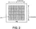
- FIG. 2depicts an exemplary light-sensing detector 200 for use with the disclosed methods and systems.
- the light-sensing detector 200includes and array of light-detecting elements 210 with each light-detecting element 210 independently capable of sensing light, converting the sensed light to an electrical quantity (e.g., current, voltage or resistance) and conveying that electrical quality to an external device, such as a digital signal processor/controller having an analog-to-digital converter.
- an electrical quantitye.g., current, voltage or resistance
- the exemplary light-sensing detector 200includes a 10-by-10 array of light-detecting elements 210 , it should be appreciated that the size of such an array can vary to as little as a 2-by-2 array (or more practically 4-by-4 array), or alternatively can exceed more than 100-by-100 elements depending on the particular circumstances of use. Further, the overall dimensions (W 1 -by-H 1 ) of the array of light-detecting element 210 can also vary as desired or otherwise required by the particular circumstances of use.
- the light-sensing detector 200 of FIG. 2can not only be used to alleviate alignment errors, but also has a number of other important advantages.
- the light-sensing detector 200can be used to sense movement in two-dimensions, as opposed to movement in a single dimension as other optical encoders are limited. Further, the light-sensing detector 200 can be used to detect eccentric motion to practically any angle with a sufficient level of precision as to ensure accurate and reliable operation of an optical encoder. Still further, the light-sensing detector 200 can be used to detect a rotation of a codescale with respect to an encoder body.
- the light-sensing detector 200can be used to detect specific shapes that may be present on a particular codescale.
- a particular codestripmay consist of alternating rectangular bars and windows across its length, but otherwise incorporate one or more unique patterns, e.g., a square, a star, a circle or the like, to signify location data, such as a center or location reference.
- shape informationcan also enable a processor to determine a particular model number or model revision as such information may be incorporated, for example, as a particular window shape, as a bar-code or even as a series of alpha-numeric characters written on the codescale.
- FIG. 3Adepicts the detector 200 of FIG. 2 with a codescale projection 310 superimposed over the detector 200 .
- the particular codescale for the exemplary systemis configured to move in a left-right direction with respect to the detector 210 , and as can be deduced by the configuration of FIG. 3A only a limited number of light-detection elements (i.e., a 5-by-10 sub-array) will be affected by the codescale's movement.
- FIG. 3Bmore clearly shows the affected light-detection elements 320 (shown as shaded), and further indicates that the codescale 310 of FIG. 3A is offset by a linear distance of D 1 , a distance that can be discerned by a processor monitoring the detector 200 .
- a processor monitoring the detector 200does not need to monitor every detection element.
- a processor monitoring the codescale's motioncan eliminate much needless processing by only monitoring the fifty affected detection elements 320 with no degradation of performance.
- FIG. 3Cdepicts an exemplary minimal subset of detection elements 330 (shown as shaded) useful to monitor codescale movement and direction. While only four detection elements 330 are used for the example of FIG. 3C , it should be appreciated that more detection elements can be used to incorporate redundancy, higher reliability or some other desirable feature. It should also be appreciated that the chosen detection elements need not be contiguous, but can be spread about any useful pattern among the fifty affected detection elements 320 . Still further, while in some embodiments the number and pattern of used detection elements may be chosen based on a minimum number of detection elements needed to perm necessary operations, other criteria may be applied including criteria related to the optimization of processing, reliability and functionality.
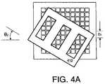
- FIG. 4Adepicts the detector 200 of FIG. 2 with a second codescale projection 410 superimposed over the detector 200 .
- the particular codescale for the exemplary systemis configured to move in an eccentric direction with respect to the detector 210 (and the related encoder body), and as can be deduced by the configuration of FIG. 4A only a limited number of light-detection elements will be affected by the codescale's movement.
- FIG. 4Bdepicts more clearly the affected light-detection elements 420 of FIG. 4A .
- Those light-detection elements that are fully affectedi.e., are subjected to complete exposure and complete shading
- those light-detection elements that are partially affectedare shown as lightly shaded.
- the codescale 410 of FIG. 4Ais offset by a linear distance of D 2 and an angular offset of ⁇ 2 , both quantities of which can be discerned by a processor monitoring the detector 200 .
- FIGS. 3A and 4Aare directed to single-direction codescale motion, it should be appreciated that by changing the codescale to incorporate a two-dimensional array of windows, the detector 200 (with supporting processor) of FIG. 2 can be used to sense motion and direction along two dimensions by monitoring the relative motion of windows superimposed over detector 200 with the caveat that all the detection elements 210 will likely be affected during operation.
- FIG. 5is a flowchart outlining an exemplary operation for calibrating and using optical encoders, such as the optical encoder with assorted components described above.
- the processstarts at step 502 where the encoder body is installed on a particular device for use, such as a printer head or printer drum.
- the related codescalee.g., codestrip or codewheel, is also installed. Control continues to step 506 .
- the codescaleis moved relative to the encoder body in order to determine the response of individual detection element of a detector in the encoder body.
- the exemplary detectorcan be an n-by-m array device, such as the 10-by-10 array shown in FIGS. 2-4C . However, as discussed above, the size, shape and resolution of the detector can change from embodiment to embodiment as may be found useful or advantageous.
- step 508the number of detection elements affected by the actions of step 506 are determined. Control continues to step 510 .
- a number of other useful propertiescan be determined based on the actions of step 506 including: linear misalignment, angular misalignment, relative angular motion of the codescale to the encoder body, model number/revision number of the codescale and/or the device using the codescale, the shape of the codescale's windows, shape of the codescale's bars, the nature of the codescale's movement (e.g., one-dimensional, two dimensional, eccentric) and so on. Control continues to step 512 .
- an appropriate set of detection elements in the detectoris selected for use.
- a setcan be the total number of detection elements affected by use (including or excluding partially affected detection elements) or some subset based on minimization of processing criteria, optimal performance criteria, redundancy/reliability criteria, a compromise of various criteria or some other useful criteria. Control continues to step 514 .
- step 514the device incorporating the codescale and encoder body of steps 502 and 504 is operated to detect any of one-dimensional movement, two-dimensional movement, eccentric movement, rotation and so on. Such operation continues as long as necessary or desired, and control continues to step 550 where the process stops.
Landscapes
- Physics & Mathematics (AREA)
- General Physics & Mathematics (AREA)
- Optical Transform (AREA)
Abstract
Description
Claims (18)
Priority Applications (3)
| Application Number | Priority Date | Filing Date | Title |
|---|---|---|---|
| US11/403,999US7525085B2 (en) | 2006-04-14 | 2006-04-14 | Multi-axis optical encoders |
| DE102007017354.9ADE102007017354B9 (en) | 2006-04-14 | 2007-04-12 | Optical coding device and calibration method |
| CN200710098106XACN101055195B (en) | 2006-04-14 | 2007-04-13 | Optical encoders |
Applications Claiming Priority (1)
| Application Number | Priority Date | Filing Date | Title |
|---|---|---|---|
| US11/403,999US7525085B2 (en) | 2006-04-14 | 2006-04-14 | Multi-axis optical encoders |
Publications (2)
| Publication Number | Publication Date |
|---|---|
| US20070241270A1 US20070241270A1 (en) | 2007-10-18 |
| US7525085B2true US7525085B2 (en) | 2009-04-28 |
Family
ID=38514881
Family Applications (1)
| Application Number | Title | Priority Date | Filing Date |
|---|---|---|---|
| US11/403,999Expired - Fee RelatedUS7525085B2 (en) | 2006-04-14 | 2006-04-14 | Multi-axis optical encoders |
Country Status (3)
| Country | Link |
|---|---|
| US (1) | US7525085B2 (en) |
| CN (1) | CN101055195B (en) |
| DE (1) | DE102007017354B9 (en) |
Cited By (4)
| Publication number | Priority date | Publication date | Assignee | Title |
|---|---|---|---|---|
| US20140071427A1 (en)* | 2012-09-07 | 2014-03-13 | Apple Inc. | Imaging range finder fabrication |
| US10184809B2 (en) | 2015-03-06 | 2019-01-22 | Hexagon Technology Center Gmbh | System for determining positions with a sensor using a 2D-code pattern for determination of a discrepancy from an ideal situation |
| US12038310B2 (en) | 2019-11-15 | 2024-07-16 | Renishaw Plc | Encoder apparatus with readhead having circuit board and a folded sheet-metal structure to support a light emitting element |
| US12072216B2 (en) | 2019-11-15 | 2024-08-27 | Renishaw Plc | Encoder apparatus and readhead |
Families Citing this family (5)
| Publication number | Priority date | Publication date | Assignee | Title |
|---|---|---|---|---|
| GB0907842D0 (en)* | 2009-05-06 | 2009-06-17 | Renishaw Plc | Position encoder apparatus and method of operation |
| EP2264409B1 (en)* | 2009-06-19 | 2015-10-07 | ASML Netherlands B.V. | Lithographic apparatus and device manufacturing method |
| CN103759660B (en) | 2014-01-28 | 2016-03-23 | 广东工业大学 | A kind of absolute grating ruler is auxiliary to be installed and error compensating method |
| US10551223B2 (en)* | 2017-03-20 | 2020-02-04 | Tt Electronics Plc | Method and apparatus for configurable photodetector array patterning for optical encoders |
| DE202018103537U1 (en)* | 2018-06-22 | 2019-10-02 | Leuze Electronic Gmbh + Co. Kg | Optical sensor |
Citations (9)
| Publication number | Priority date | Publication date | Assignee | Title |
|---|---|---|---|---|
| US4572952A (en)* | 1982-07-28 | 1986-02-25 | Adrian March Research Ltd. | Position sensor with moire interpolation |
| US5317149A (en)* | 1992-11-12 | 1994-05-31 | Hewlett-Packard Company | Optical encoder with encapsulated electrooptics |
| US6564168B1 (en)* | 1999-09-14 | 2003-05-13 | Immersion Corporation | High-resolution optical encoder with phased-array photodetectors |
| US20030193016A1 (en)* | 2002-04-11 | 2003-10-16 | Chin Yee Loong | Dual-axis optical encoder device |
| US6664535B1 (en)* | 2002-07-16 | 2003-12-16 | Mitutoyo Corporation | Scale structures and methods usable in an absolute position transducer |
| US20050072912A1 (en)* | 2003-08-06 | 2005-04-07 | Hamamatsu Photonics K.K. | Absolute encoder |
| US7060968B1 (en)* | 2002-06-04 | 2006-06-13 | The United States Of America As Represented By The Administrator Of The National Aeronautics And Space Administration | Method and apparatus for optical encoding with compressible imaging |
| US20060243895A1 (en)* | 2003-04-22 | 2006-11-02 | Mikael Nordenfelt | Method and apparatus for absolute optical encoders with reduced sensitivity to scale or disk mounting errors |
| US7309855B2 (en)* | 2004-07-26 | 2007-12-18 | Sharp Kabushiki Kaisha | Reflective encoder with light shield and electronic device using such reflective encoder |
Family Cites Families (2)
| Publication number | Priority date | Publication date | Assignee | Title |
|---|---|---|---|---|
| JP2001311630A (en)* | 2000-02-22 | 2001-11-09 | Mitsutoyo Corp | Optical encoder |
| JP4444469B2 (en)* | 2000-08-07 | 2010-03-31 | 株式会社ミツトヨ | Optical displacement measuring device |
- 2006
- 2006-04-14USUS11/403,999patent/US7525085B2/ennot_activeExpired - Fee Related
- 2007
- 2007-04-12DEDE102007017354.9Apatent/DE102007017354B9/ennot_activeExpired - Fee Related
- 2007-04-13CNCN200710098106XApatent/CN101055195B/ennot_activeExpired - Fee Related
Patent Citations (9)
| Publication number | Priority date | Publication date | Assignee | Title |
|---|---|---|---|---|
| US4572952A (en)* | 1982-07-28 | 1986-02-25 | Adrian March Research Ltd. | Position sensor with moire interpolation |
| US5317149A (en)* | 1992-11-12 | 1994-05-31 | Hewlett-Packard Company | Optical encoder with encapsulated electrooptics |
| US6564168B1 (en)* | 1999-09-14 | 2003-05-13 | Immersion Corporation | High-resolution optical encoder with phased-array photodetectors |
| US20030193016A1 (en)* | 2002-04-11 | 2003-10-16 | Chin Yee Loong | Dual-axis optical encoder device |
| US7060968B1 (en)* | 2002-06-04 | 2006-06-13 | The United States Of America As Represented By The Administrator Of The National Aeronautics And Space Administration | Method and apparatus for optical encoding with compressible imaging |
| US6664535B1 (en)* | 2002-07-16 | 2003-12-16 | Mitutoyo Corporation | Scale structures and methods usable in an absolute position transducer |
| US20060243895A1 (en)* | 2003-04-22 | 2006-11-02 | Mikael Nordenfelt | Method and apparatus for absolute optical encoders with reduced sensitivity to scale or disk mounting errors |
| US20050072912A1 (en)* | 2003-08-06 | 2005-04-07 | Hamamatsu Photonics K.K. | Absolute encoder |
| US7309855B2 (en)* | 2004-07-26 | 2007-12-18 | Sharp Kabushiki Kaisha | Reflective encoder with light shield and electronic device using such reflective encoder |
Cited By (6)
| Publication number | Priority date | Publication date | Assignee | Title |
|---|---|---|---|---|
| US20140071427A1 (en)* | 2012-09-07 | 2014-03-13 | Apple Inc. | Imaging range finder fabrication |
| US9506750B2 (en) | 2012-09-07 | 2016-11-29 | Apple Inc. | Imaging range finding device and method |
| US9683841B2 (en)* | 2012-09-07 | 2017-06-20 | Apple Inc. | Imaging range finder fabrication |
| US10184809B2 (en) | 2015-03-06 | 2019-01-22 | Hexagon Technology Center Gmbh | System for determining positions with a sensor using a 2D-code pattern for determination of a discrepancy from an ideal situation |
| US12038310B2 (en) | 2019-11-15 | 2024-07-16 | Renishaw Plc | Encoder apparatus with readhead having circuit board and a folded sheet-metal structure to support a light emitting element |
| US12072216B2 (en) | 2019-11-15 | 2024-08-27 | Renishaw Plc | Encoder apparatus and readhead |
Also Published As
| Publication number | Publication date |
|---|---|
| US20070241270A1 (en) | 2007-10-18 |
| CN101055195B (en) | 2011-02-09 |
| DE102007017354B9 (en) | 2016-03-24 |
| DE102007017354B4 (en) | 2016-01-21 |
| DE102007017354A1 (en) | 2007-10-18 |
| CN101055195A (en) | 2007-10-17 |
Similar Documents
| Publication | Publication Date | Title |
|---|---|---|
| US7525085B2 (en) | Multi-axis optical encoders | |
| US7399956B2 (en) | Optical encoder with sinusoidal photodetector output signal | |
| JP5063963B2 (en) | Optical encoder with integrated index channel | |
| US7495583B2 (en) | Flat-top reflection-based optical encoders | |
| US5300961A (en) | Method and apparatus for aligning multiple print bars in a single pass system | |
| EP2662668B1 (en) | Scale, vernier encoder and apparatus using the same | |
| GB2430818A (en) | Optical encoder indicating rotational and non-rotational movement | |
| WO1993025865A1 (en) | Position detection system | |
| US20070241271A1 (en) | Reflection-based optical encoders having no code medium | |
| US7377435B2 (en) | Optical encoder | |
| US7348547B2 (en) | Position detecting apparatus and image processing apparatus provided with the same | |
| JP2002039797A (en) | Encoder | |
| US20070241269A1 (en) | Optical encoders having improved resolution | |
| JP5327931B2 (en) | Optical encoder with contamination detection | |
| US7056041B2 (en) | Encoder strip damage detector | |
| US7995217B2 (en) | High-resolution encoder array | |
| US20030062467A1 (en) | System and methodology for the use of optical positioning system for scanners | |
| US20240200988A1 (en) | Encoder | |
| JPS612017A (en) | Linear position encoder | |
| JPH0416967A (en) | Optical writing device | |
| JP2002144629A (en) | Print position detector for electrophotographic apparatus, and print position correction method for electrophotographic apparatus |
Legal Events
| Date | Code | Title | Description |
|---|---|---|---|
| AS | Assignment | Owner name:AVAGO TECHNOLOGIES GENERAL IP (SINGAPORE) PTE.LTD. Free format text:ASSIGNMENT OF ASSIGNORS INTEREST;ASSIGNORS:SAIDAN, SAIFUL BAHARA;YEOH, THENG HOOI;CHEAH, CHIANG SUN;AND OTHERS;REEL/FRAME:017792/0101 Effective date:20060413 | |
| AS | Assignment | Owner name:AVAGO TECHNOLOGIES GENERAL IP (SINGAPORE) PTE. LTD Free format text:ASSIGNMENT OF ASSIGNORS INTEREST;ASSIGNORS:SAIDAN, SAIFUL BAHARI;YEOH, THENG HOOI;CHEAH, CHIANG SUN;AND OTHERS;REEL/FRAME:019495/0569;SIGNING DATES FROM 20060413 TO 20060807 | |
| STCF | Information on status: patent grant | Free format text:PATENTED CASE | |
| FPAY | Fee payment | Year of fee payment:4 | |
| AS | Assignment | Owner name:DEUTSCHE BANK AG NEW YORK BRANCH, AS COLLATERAL AGENT, NEW YORK Free format text:PATENT SECURITY AGREEMENT;ASSIGNOR:AVAGO TECHNOLOGIES GENERAL IP (SINGAPORE) PTE. LTD.;REEL/FRAME:032851/0001 Effective date:20140506 Owner name:DEUTSCHE BANK AG NEW YORK BRANCH, AS COLLATERAL AG Free format text:PATENT SECURITY AGREEMENT;ASSIGNOR:AVAGO TECHNOLOGIES GENERAL IP (SINGAPORE) PTE. LTD.;REEL/FRAME:032851/0001 Effective date:20140506 | |
| AS | Assignment | Owner name:AVAGO TECHNOLOGIES GENERAL IP (SINGAPORE) PTE. LTD., SINGAPORE Free format text:TERMINATION AND RELEASE OF SECURITY INTEREST IN PATENT RIGHTS (RELEASES RF 032851-0001);ASSIGNOR:DEUTSCHE BANK AG NEW YORK BRANCH, AS COLLATERAL AGENT;REEL/FRAME:037689/0001 Effective date:20160201 Owner name:AVAGO TECHNOLOGIES GENERAL IP (SINGAPORE) PTE. LTD Free format text:TERMINATION AND RELEASE OF SECURITY INTEREST IN PATENT RIGHTS (RELEASES RF 032851-0001);ASSIGNOR:DEUTSCHE BANK AG NEW YORK BRANCH, AS COLLATERAL AGENT;REEL/FRAME:037689/0001 Effective date:20160201 | |
| AS | Assignment | Owner name:BANK OF AMERICA, N.A., AS COLLATERAL AGENT, NORTH CAROLINA Free format text:PATENT SECURITY AGREEMENT;ASSIGNOR:AVAGO TECHNOLOGIES GENERAL IP (SINGAPORE) PTE. LTD.;REEL/FRAME:037808/0001 Effective date:20160201 Owner name:BANK OF AMERICA, N.A., AS COLLATERAL AGENT, NORTH Free format text:PATENT SECURITY AGREEMENT;ASSIGNOR:AVAGO TECHNOLOGIES GENERAL IP (SINGAPORE) PTE. LTD.;REEL/FRAME:037808/0001 Effective date:20160201 | |
| FPAY | Fee payment | Year of fee payment:8 | |
| AS | Assignment | Owner name:AVAGO TECHNOLOGIES GENERAL IP (SINGAPORE) PTE. LTD., SINGAPORE Free format text:TERMINATION AND RELEASE OF SECURITY INTEREST IN PATENTS;ASSIGNOR:BANK OF AMERICA, N.A., AS COLLATERAL AGENT;REEL/FRAME:041710/0001 Effective date:20170119 Owner name:AVAGO TECHNOLOGIES GENERAL IP (SINGAPORE) PTE. LTD Free format text:TERMINATION AND RELEASE OF SECURITY INTEREST IN PATENTS;ASSIGNOR:BANK OF AMERICA, N.A., AS COLLATERAL AGENT;REEL/FRAME:041710/0001 Effective date:20170119 | |
| AS | Assignment | Owner name:AVAGO TECHNOLOGIES INTERNATIONAL SALES PTE. LIMITE Free format text:MERGER;ASSIGNOR:AVAGO TECHNOLOGIES GENERAL IP (SINGAPORE) PTE. LTD.;REEL/FRAME:047195/0827 Effective date:20180509 | |
| AS | Assignment | Owner name:AVAGO TECHNOLOGIES INTERNATIONAL SALES PTE. LIMITE Free format text:CORRECTIVE ASSIGNMENT TO CORRECT THE EFFECTIVE DATE OF MERGER PREVIOUSLY RECORDED AT REEL: 047195 FRAME: 0827. ASSIGNOR(S) HEREBY CONFIRMS THE MERGER;ASSIGNOR:AVAGO TECHNOLOGIES GENERAL IP (SINGAPORE) PTE. LTD.;REEL/FRAME:047924/0571 Effective date:20180905 | |
| FEPP | Fee payment procedure | Free format text:MAINTENANCE FEE REMINDER MAILED (ORIGINAL EVENT CODE: REM.); ENTITY STATUS OF PATENT OWNER: LARGE ENTITY | |
| LAPS | Lapse for failure to pay maintenance fees | Free format text:PATENT EXPIRED FOR FAILURE TO PAY MAINTENANCE FEES (ORIGINAL EVENT CODE: EXP.); ENTITY STATUS OF PATENT OWNER: LARGE ENTITY | |
| STCH | Information on status: patent discontinuation | Free format text:PATENT EXPIRED DUE TO NONPAYMENT OF MAINTENANCE FEES UNDER 37 CFR 1.362 | |
| FP | Lapsed due to failure to pay maintenance fee | Effective date:20210428 |