US7524325B2 - Fastener retention system - Google Patents
Fastener retention systemDownload PDFInfo
- Publication number
- US7524325B2 US7524325B2US10/693,699US69369903AUS7524325B2US 7524325 B2US7524325 B2US 7524325B2US 69369903 AUS69369903 AUS 69369903AUS 7524325 B2US7524325 B2US 7524325B2
- Authority
- US
- United States
- Prior art keywords
- ring
- screw
- bone
- head
- split ring
- Prior art date
- Legal status (The legal status is an assumption and is not a legal conclusion. Google has not performed a legal analysis and makes no representation as to the accuracy of the status listed.)
- Expired - Lifetime, expires
Links
Images


Classifications
- A—HUMAN NECESSITIES
- A61—MEDICAL OR VETERINARY SCIENCE; HYGIENE
- A61B—DIAGNOSIS; SURGERY; IDENTIFICATION
- A61B17/00—Surgical instruments, devices or methods
- A61B17/56—Surgical instruments or methods for treatment of bones or joints; Devices specially adapted therefor
- A61B17/58—Surgical instruments or methods for treatment of bones or joints; Devices specially adapted therefor for osteosynthesis, e.g. bone plates, screws or setting implements
- A61B17/68—Internal fixation devices, including fasteners and spinal fixators, even if a part thereof projects from the skin
- A61B17/80—Cortical plates, i.e. bone plates; Instruments for holding or positioning cortical plates, or for compressing bones attached to cortical plates
- A61B17/8033—Cortical plates, i.e. bone plates; Instruments for holding or positioning cortical plates, or for compressing bones attached to cortical plates having indirect contact with screw heads, or having contact with screw heads maintained with the aid of additional components, e.g. nuts, wedges or head covers
- A61B17/8042—Cortical plates, i.e. bone plates; Instruments for holding or positioning cortical plates, or for compressing bones attached to cortical plates having indirect contact with screw heads, or having contact with screw heads maintained with the aid of additional components, e.g. nuts, wedges or head covers the additional component being a cover over the screw head
- A—HUMAN NECESSITIES
- A61—MEDICAL OR VETERINARY SCIENCE; HYGIENE
- A61B—DIAGNOSIS; SURGERY; IDENTIFICATION
- A61B17/00—Surgical instruments, devices or methods
- A61B17/56—Surgical instruments or methods for treatment of bones or joints; Devices specially adapted therefor
- A61B17/58—Surgical instruments or methods for treatment of bones or joints; Devices specially adapted therefor for osteosynthesis, e.g. bone plates, screws or setting implements
- A61B17/68—Internal fixation devices, including fasteners and spinal fixators, even if a part thereof projects from the skin
- A61B17/70—Spinal positioners or stabilisers, e.g. stabilisers comprising fluid filler in an implant
- A61B17/7059—Cortical plates
- A—HUMAN NECESSITIES
- A61—MEDICAL OR VETERINARY SCIENCE; HYGIENE
- A61B—DIAGNOSIS; SURGERY; IDENTIFICATION
- A61B17/00—Surgical instruments, devices or methods
- A61B17/56—Surgical instruments or methods for treatment of bones or joints; Devices specially adapted therefor
- A61B17/58—Surgical instruments or methods for treatment of bones or joints; Devices specially adapted therefor for osteosynthesis, e.g. bone plates, screws or setting implements
- A61B17/68—Internal fixation devices, including fasteners and spinal fixators, even if a part thereof projects from the skin
- A61B17/80—Cortical plates, i.e. bone plates; Instruments for holding or positioning cortical plates, or for compressing bones attached to cortical plates
- A61B17/8033—Cortical plates, i.e. bone plates; Instruments for holding or positioning cortical plates, or for compressing bones attached to cortical plates having indirect contact with screw heads, or having contact with screw heads maintained with the aid of additional components, e.g. nuts, wedges or head covers
- A61B17/8047—Cortical plates, i.e. bone plates; Instruments for holding or positioning cortical plates, or for compressing bones attached to cortical plates having indirect contact with screw heads, or having contact with screw heads maintained with the aid of additional components, e.g. nuts, wedges or head covers wherein the additional element surrounds the screw head in the plate hole
Definitions
- the present inventionrelates to orthopedic implantable devices, related systems, and associated methods of use and, more particularly, to a plate system and associated method for joining two or more bone segments, such as vertebrae.
- stabilization or controlled movementis desirable when repairing bone segments that have become deteriorated, damaged or degenerative, such as due to trauma or disease.
- Such stabilization or controlled movementmay be used in cooperation with one or more fusion or stabilizing devices, or may be used alone.
- a vertebral plate system and associated methodminimizes the number of required multiple configurations and sizes of hardware on hand during surgery for repair, stabilization or fusion of bone segments.
- a novel aspect of the inventionis a resilient split ring that cooperates with angled contact surfaces in a plate for allowing convenient and fast dynamic locking between the plate and a bone screw.
- the present inventionis directed to a screw or similarly elongated fastener having a generally spherical or part-spherical head with a section of helical threads being configured in a generally horizontal band and positioned around a maximum-diameter section of the head.
- the screwis loosely retained to a first structure by a snap-ring formed from a ring of elastic material having a slot cut so that the ring is a “C” ring.
- the ringis seated on an annular shoulder formed in a through-hole in the first structure.
- the section of the through-hole above the shouldertapers inwardly in an upward direction to a minimum diameter that is smaller than the outside diameter of the ring when the ring is in an un-stressed state.
- the inner diameter of the ringhas an edge that is adapted to cooperate with and ride in the threads on the screw head.
- the ringIn operation, the ring is flexed or stressed in a manner to push it through the minimum diameter section at the top of the through hole of the first structure. After the ring passes down the through-hole it rests upon the shoulder and is expanded to its unstressed state.
- the shaft section of the screwis advanced through the ring and throughhole until the screw head begins to pass through the inner diameter of the ring.
- the maximum diameter section with threadsapproaches the ring.
- the ringgets slightly expanded as the maximum diameter section approaches the ring edge. At this point, further advancement of the screw causes the edge of the ring to engage the threads on the screw head.
- the return force of the ring that biases it toward its un-stressed positioncauses the ring to slide up on the spherical head of the screw until it reaches an un-stressed condition, at which point the screw head cannot be backed out of the ring or the through-hole. This is because if the screw is merely pushed upward, the ring will be pushed up against the minimum diameter area of the tapered through hole and constrained against expansion adequate to let the screw head pass.
- the screwcan be a bone screw for joining a first structure, such as a cervical plate, to a second structure such as a vertebrae.
- the screwwill have a threaded shaft adapted to be driven into a hole in said vertebrae.
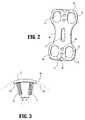
- FIG. 2is a partial, anterior view of the preferred embodiment of the present invention plate system.
- FIG. 3is a top view of the preferred embodiment of the present invention plate system.
- FIG. 4is a partially exploded perspective view of the preferred embodiment of the present invention plate system.
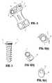
- FIG. 5is a front view of a first embodiment bone screw fastener according-to the present invention plate system.
- FIGS. 6( a )- 6 ( c )are perspective views of various alternative bone screw sleeve arrangements according to the present invention.
- FIG. 7is a front, cross-sectional view of a second embodiment bone screw fastener according to the present invention plate system.
- FIG. 8is a partial, side view of the preferred embodiment of the present invention plate system.
- FIG. 9is a perspective view of a second embodiment of the present invention plate system.
- FIG. 10is a partial, cross-sectional view of a third embodiment of the present invention plate system directed to a locking system for retaining a plate to bone structure.
- FIG. 11is a side view of a bone screw according to the third embodiment of the present invention.
- FIG. 12is a front and side view of a locking ring according to the third embodiment of the present invention.
- FIG. 13is a side, cross-sectional view of the locking ring according to FIG. 12 .
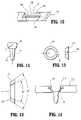
- FIG. 15is a partial, side cross-sectional view of a plate with bone screw and locking ring assembled and locked according to the third embodiment of the present invention.
- FIG. 16is a cross-sectional view of a bone screw according to the third embodiment of the present invention.
- FIG. 17is a side view of an insertion instrument for use with a bone screw and locking ring according to the third embodiment of the present invention.
- FIG. 18is a partial side view of the insertion instrument of FIG. 17 .
- FIG. 19is a partial side view of the insertion instrument, plate, bone screw and locking ring according, to the third embodiment of the present invention.
- FIG. 20is a front view of a screw according to the present invention assembly.
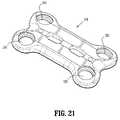
- FIG. 21is a perspective view of a bone plate according to the present invention assembly.
- FIG. 22is a side, cross-sectional view of a retention ring and a partial view of the plate according to the present invention.
- FIG. 23is a side, cross-sectional view of a retention ring and a partial view of the plate according to the present invention, in which the screw of FIG. 20 is partially advance through the ring.
- FIG. 24is a side, cross-sectional view of a retention ring and a partial view of the plate according to the present invention, in which the screw of FIG. 20 is fully advanced through the ring.
- FIG. 25is a top view of the ring component according to the-present invention.
- the present invention system and methodmay be used to join a variety of bone segments for stabilization, controlled or restricted movement, and/or fusion.
- the present inventionis particularly well-suited for use in joining vertebral bodies and, thus, is presented for use in joining cervical vertebrae in the description of the preferred embodiment. This is not intended, however, to be limiting on the scope of the present invention.
- FIG. 1there is shown schematically a group of cervical vertebral bodies ( 10 ) comprising two adjacent vertebrae ( 12 , 14 ) having a disc space ( 16 ) therebetween, viewed from a side view or medial perspective.
- a plate ( 18 ) according to the present inventionis shown fastened to the anterior side ( 20 ) of the column of vertebrae in a manner bridging across the disc space ( 16 ).
- Bone screws ( 22 , 24 )are used to fasten the plate in position in accordance with the present invention to stabilize the vertebrae ( 12 , 14 ) for controlled movement or fusion.
- the cross-sectional shape of the plate ( 18 )is such that the radius ( 50 ) of the outer surface ( 52 ) is smaller than the radius ( 54 ) of the inner surface ( 56 ) which contacts the vertebrae ( 12 , 14 ).
- This featurefacilitates optimal fit and positioning of bone screws or fasteners ( 72 ) such that they are angled inward toward each other.
- the, fasteners ( 72 )are angled at about 6 degrees with respect to a direction normal to a tangent at the midpoint of the inner surface ( 56 ). This arrangement inherently reduces pullout susceptibility.
- a sleeve ( 58 )is positioned in each fastener slot ( 30 , 32 , 34 , 36 ).
- Each sleeve ( 58 )is retained in the plate ( 18 ) by a sleeve cover ( 60 ) positioned at each end ( 26 , 28 ) of the plate ( 18 ).
- Each sleeve cover ( 60 )fits into one of the recessed areas ( 42 ), respectively, and is fixed to the plate ( 18 ) by a lock screw ( 62 ) passing through a central hole ( 64 ) in the sleeve cover ( 60 ) which is aligned with the lock screw hole ( 44 ) for threadedly receiving the lock screw ( 62 ) therein.
- each sleeve cover ( 60 )overlaps the tops of the respective sleeves ( 58 ) to prevent them from backing up and out of the plate ( 18 ).
- Each sleeve ( 58 )includes a bone fastener hole ( 66 ) having threads ( 68 ) therein to retain the head ( 70 ) of a bone fastener ( 72 ) in the plate ( 18 ). Tightening each threaded head ( 70 ) causes the sleeves ( 58 ) to expand into locking engagement with the plate ( 18 ).
- a snap ring ( 76 ) and cooperating channel ( 78 )may be used in lieu of a threaded head connection.
- each sleeve ( 58 )is round in top view and, thus, slideable within each groove ( 30 ).
- each sleeve ( 58 )has a semispherical lower portion ( 74 ) adapted to sit in a similarly shaped cup or seat ( 80 ) to allow relative pivoting of the sleeve ( 58 ) and fastener ( 72 ) with respect to the plate ( 18 ). Pivoting is preferably about 10 degrees from the axis, as shown in FIG. 8 .
- This mode of enabling sliding movement and angular adjustment of the fastener ( 72 ) relative to the plate ( 18 )is referred to as a “fully dynamized” mode.
- the permitted slidingminimizes friction wear.
- a graftmay be provided with in-line dynamic compression as the grooves ( 30 , 32 , 34 , 36 ) are tangent to the lordotic curve of the plate ( 18 ).
- a crescent shaped insert ( 82 )may be positioned in one or more of the grooves ( 30 ) to constrain the sleeve ( 58 ) from translation within the groove while allowing pivoting of the sleeve ( 58 ) and fastener ( 72 ) with respect to the plate ( 18 ).
- the crescent insert ( 82 )has a concave end ( 84 ) and a convex end ( 86 ).
- the concave end ( 84 )forms a semi-spherical cup section for enabling the sleeve ( 58 ) and fastener ( 72 ) to pivot relative to the plate ( 18 ). This mode allows variable angle adjustment of the bone fastener ( 72 ) while prohibiting sliding movement.
- FIG. 6( c )Another alternative for mounting the fastener ( 72 ) to the plate ( 18 ) is a fixed angle mode in which the bone fastener ( 72 ) neither slides nor rotates, as shown in FIG. 6( c ).
- Thisis accomplished by using a modified sleeve ( 88 ) that is shaped and sized to fill the entire groove ( 30 ).
- the modified sleeve ( 88 )cannot slide within the groove ( 30 ) and it has a threaded opening ( 90 ) adapted to fixedly attach the fastener ( 72 ) thereto.
- each sleeve cover ( 60 )has a probe insertion hole ( 92 ) that aligns with the probe insertion hole ( 46 ) of the plate ( 18 ) when the sleeve cover ( 60 ) is positioned thereon.
- the two probe insertion holes ( 46 , 92 ), when aligned,allow a probe or other instrument (not shown) to be positioned therein to pin or hold the plate ( 18 ) against the bone or vertebrae to which the plate ( 18 ) will be fastened during installation.
- Each sleeve cover ( 60 )also includes an apex cutout ( 94 ) that, when aligned with the apex recess ( 48 ) of the plate ( 18 ), provides clearance for the esophagus of a patient in which the plate ( 18 ) is installed in the cervical region.
- the plate ( 18 )is positioned against the vertebrae ( 12 , 14 ) to be joined and held in place while a plurality of fasteners ( 72 ) are inserted through the grooves ( 30 , 32 , 34 , 36 ) and driven into the vertebrae ( 12 , 14 ).
- Each fastener ( 72 )is mated with one of the sleeve ( 58 ) or modified sleeve ( 88 ).
- the sleeve covers ( 60 )are fastened to the plate ( 18 ) using lock screws ( 62 ) so that the sleeve covers ( 60 ) overlap and prevent backing out by the fasteners ( 72 ).
- a plate ( 100 )according to another embodiment of the present invention has three sets of grooves ( 102 ) adapted to receive a total of six bone fasteners (not shown) and adapted to span and connect three vertebrae.
- the plate ( 100 )is similar to the above-described first embodiment in other respects.
- a vertebral plate( 203 ) includes at least one hole ( 204 ) having a conical section ( 205 ) and a hemispherical section ( 206 ).
- a tapered lock ring( 208 ) has a cut ( 210 ) so that it forms a resilient “C” shaped ring.
- the ring ( 208 )has an outside diameter angle ⁇ and an inside diameter angle ⁇ .
- angle ⁇is greater than angle ⁇ , but this may be varied according to desired performance, material properties, and surrounding geometric parameters.
- the lock ring ( 208 )is flexed to pass it though the opening ( 212 ) of the hole ( 204 ) until it re-expands and rests on a shoulder ( 214 ) that separates the conical section ( 205 ) from the hemispherical section ( 206 ), as shown in FIG. 10 .
- a bone screw ( 214 ) having a generally spherical or partially spherical head ( 216 ) and a bone-engaging shaft ( 218 ) such as a threaded shaftis passed through the hole ( 204 ) and ring ( 208 ).
- the maximum diameter section of the screw head ( 216 )is greater than the inner diameter of the lock ring ( 208 ) such that, when pushed through the lock ring ( 208 ), the screw head ( 216 ) expands the ring ( 208 ) as shown in FIG. 14 .
- the ring ( 208 )rises upwardly along the contours of the screw head ( 216 ) under its own kinetic energy that causes it to return to its original shape, as shown in FIG. 15 .
- the conical section ( 205 ) of the hole ( 204 )mates with the exterior, angled surface ( 220 ) of the ring ( 208 ).
- Torque and rotational movementmay be applied to the bone screw ( 214 ) by a driver instrument ( 222 ).
- the driver ( 222 )comprises a shaft ( 224 ), a handle ( 226 ), and a screw-engaging head ( 228 ).
- the head ( 228 )may have flats ( 230 ) arid a snap ring ( 232 ).
- the flats ( 230 )cooperate with flats ( 234 ) and a ring groove ( 236 ) in an opening ( 238 ) in the screw head ( 216 ).
- Such torque and rotational movementare applied to the bone screw ( 214 ), which is typically threaded, during insertion or removal.
- the sleevescould be assembled in the plate by chilling the sleeve and heating the plate to cause corresponding respective contraction and expansion, such that when the respective temperatures return to ambient conditions the fasteners, sleeves and plate are relatively locked to each other.
- the present inventioncan be used with or without fusion elements including fusion inserts and fillers such as bone pastes, bone chips and bone morphogenic proteins (BMP). It may also be used by itself or in combination with other devices and it may be used in the cervical spinal applications or other types including lumbar.
- fusion elementsincluding fusion inserts and fillers such as bone pastes, bone chips and bone morphogenic proteins (BMP). It may also be used by itself or in combination with other devices and it may be used in the cervical spinal applications or other types including lumbar.
- Another embodiment of the present inventionhas various application in which a first structure retains a fastener before, during and after being joined to a second structure by the fastener. While the preferred embodiment is directed to a bone screw for joining a cervical plate vertebral bone, the embodiment is by way of example and is not intended to limit the scope of the invention.
- a bone screw ( 310 )has a shaft portion ( 312 ) which can be threaded, a generally spherical head section ( 314 ), and a threaded section ( 316 ) of helical threads spanning the maximum horizontal diameter.
- a conventional driver engagement configuration (not shown) on the top of the head ( 314 )such as a slot, a hexagonal hole, or the like is provided to enable rotational force to be applied to the screw ( 310 ) for rotationally driving the screw ( 310 ).
- the screw ( 310 )may be made of titanium, stainless steel, or other suitable materials.
- the head ( 314 )may be a fill sphere, a part-sphere, or a similar configuration in which a maximum horizontal diameter occurs between upper and lower axial sections of the head.
- a cervical plate ( 318 ) of the type generally known for joining two adjacent vertebra in a stabilizing manneris provided with a plurality of screw holes ( 320 ), each adapted to receive the ring component ( 332 ) and screw ( 310 ) assembly according to the present invention.
- each hole ( 320 ) in the plate ( 318 )has an upper minimum diameter section ( 324 ), a tapered section ( 326 ) that tapers outwardly in a generally increasing diameter manner downwardly from the upper minimum diameter section ( 324 ), a shoulder ( 328 ), and a generally tapered seat section ( 330 ).
- a retention ring ( 332 )also shown in top view in FIG. 25 , has an inner diameter edge ( 334 ), an inner diameter upwardly tapering wall ( 336 ), an outer diameter upwardly tapering wall ( 338 ), and a slot ( 340 ).
- the retention ring ( 332 )is made from a resilient material that allows it to be stressed or compressed in a manner that allows it to be pressed past the minimum diameter section ( 324 ) and into the hole ( 320 ) until it sits on the shoulder ( 328 ). While seated on the shoulder ( 328 ), the ring ( 332 ) has expanded back to its un-stressed shape since the inner diameter of the tapered section ( 326 ) near the shoulder ( 328 ) is greater than the outside diameter of the ring ( 332 ).
- the screw ( 310 )is placed through the ring ( 332 ) and hole ( 320 ) and advanced, for example into a vertebral bone, until the head ( 314 ) engages the ring ( 332 ). As the maximum horizontal diameter of the head ( 314 ) moves toward the edge ( 334 ) the ring ( 332 ) slightly expands until the edge ( 334 ) enters the threads ( 316 ), as shown in FIG. 24 . At this point, the screw ( 310 ) is axially advanced further by rotation so the threads ( 316 ) ride along the edge ( 334 ). As the edge ( 334 ) moves past the threaded section ( 316 ), it engages the smooth, spherical head of the screw ( 310 ) above the threads ( 316 ), as shown in FIG. 25 .
- the ring ( 310 )preferably has a tapered inside wall ( 336 ) and a tapered outside wall ( 338 ).
- the hole ( 320 )preferably has a tapered section ( 326 ). This combination enables the ring ( 310 ) to be wedged between the screw ( 310 ) and the plate ( 318 ) by the upward force of the screw head ( 310 ) which imparts both vertical and horizontal forces to the ring's inner wall ( 336 ) which, in turn, are transmitted to the hole's inner wall ( 326 ) via the outer wall ( 338 ). If upward force of the screw ( 310 ) is increased, the ring ( 310 ) is wedged tighter.
- the screw head ( 314 )is supported and prevented from slipping out of the hole ( 320 ) on the bottom side by a seat ( 330 ).
- the seat ( 330 )may be tapered, conical of hemi-spherical.
- a narrow instrument(not shown) must be inserted to push downwardly on the ring ( 332 ), causing it to expand slightly around the screw head ( 314 ) until the inside edge ( 334 ) engages the screw thread ( 314 ), at which time counter-rotation will advance the screw head ( 314 ) through and out of the ring ( 332 ) and through-hole ( 320 ) in a manner opposite of its insertion.
Landscapes
- Health & Medical Sciences (AREA)
- Orthopedic Medicine & Surgery (AREA)
- Life Sciences & Earth Sciences (AREA)
- Surgery (AREA)
- Neurology (AREA)
- Heart & Thoracic Surgery (AREA)
- Engineering & Computer Science (AREA)
- Biomedical Technology (AREA)
- Nuclear Medicine, Radiotherapy & Molecular Imaging (AREA)
- Medical Informatics (AREA)
- Molecular Biology (AREA)
- Animal Behavior & Ethology (AREA)
- General Health & Medical Sciences (AREA)
- Public Health (AREA)
- Veterinary Medicine (AREA)
- Prostheses (AREA)
- Surgical Instruments (AREA)
Abstract
Description
Claims (6)
Priority Applications (1)
| Application Number | Priority Date | Filing Date | Title |
|---|---|---|---|
| US10/693,699US7524325B2 (en) | 2002-11-04 | 2003-10-27 | Fastener retention system |
Applications Claiming Priority (4)
| Application Number | Priority Date | Filing Date | Title |
|---|---|---|---|
| US42297802P | 2002-11-04 | 2002-11-04 | |
| US47664203P | 2003-06-09 | 2003-06-09 | |
| US47979703P | 2003-06-20 | 2003-06-20 | |
| US10/693,699US7524325B2 (en) | 2002-11-04 | 2003-10-27 | Fastener retention system |
Publications (2)
| Publication Number | Publication Date |
|---|---|
| US20040087951A1 US20040087951A1 (en) | 2004-05-06 |
| US7524325B2true US7524325B2 (en) | 2009-04-28 |
Family
ID=32180697
Family Applications (1)
| Application Number | Title | Priority Date | Filing Date |
|---|---|---|---|
| US10/693,699Expired - LifetimeUS7524325B2 (en) | 2002-11-04 | 2003-10-27 | Fastener retention system |
Country Status (1)
| Country | Link |
|---|---|
| US (1) | US7524325B2 (en) |
Cited By (45)
| Publication number | Priority date | Publication date | Assignee | Title |
|---|---|---|---|---|
| US20070055252A1 (en)* | 2005-03-17 | 2007-03-08 | Jason Blain | Flanged interbody fusion device with oblong fastener apertures |
| US20080009870A1 (en)* | 2002-10-28 | 2008-01-10 | Alan Lombardo | Bone plate assembly provided with screw locking mechanisms |
| US20080083613A1 (en)* | 2006-10-06 | 2008-04-10 | Nelson Oi | Port structures for non-rigid bone plates |
| US20080097457A1 (en)* | 2004-10-25 | 2008-04-24 | Warnick David R | Pedicle screw systems and methods of assembling/installing the same |
| US20080103503A1 (en)* | 2005-01-17 | 2008-05-01 | Didier Roux | Fastener System of the Captive Screw Type |
| US20080249576A1 (en)* | 2005-10-25 | 2008-10-09 | Hawkes David T | Pedicle Screw System Configured to Receive a Straight or Curved Rod |
| US20090157121A1 (en)* | 2007-12-13 | 2009-06-18 | Harris Peter M | Dynamic anterior vertebral plate |
| US20090182383A1 (en)* | 2008-01-14 | 2009-07-16 | Amedica Corporation | Bone fixation plate with anchor retaining member |
| US20100152788A1 (en)* | 2005-10-04 | 2010-06-17 | X-Spine Systems, Inc. | Pedicle screw system with provisional locking aspects |
| US20100249937A1 (en)* | 2009-03-27 | 2010-09-30 | Spinal Elements, Inc. | Flanged interbody fusion device |
| US20110172666A1 (en)* | 2010-01-08 | 2011-07-14 | Heilman Benjamin P | Variable angle locking screw |
| US8066745B2 (en) | 2005-07-29 | 2011-11-29 | X-Spine Systems, Inc. | Capless multiaxial screw and spinal fixation assembly and method |
| CN102293681A (en)* | 2011-08-25 | 2011-12-28 | 尚鹏 | Rotary stop type anterior cervical inner fixing device |
| US20120065690A1 (en)* | 2004-02-26 | 2012-03-15 | Scott Perrow | Bone Plate System |
| US8147522B2 (en) | 2004-10-25 | 2012-04-03 | X-Spine Systems, Inc. | Bone fixation method |
| US20130053887A1 (en)* | 2011-08-26 | 2013-02-28 | Life Spine, Inc. | Bone Screw Retention in a Spinal Implant |
| US8668723B2 (en) | 2011-07-19 | 2014-03-11 | Neurostructures, Inc. | Anterior cervical plate |
| US8728129B2 (en) | 2011-01-07 | 2014-05-20 | Biomet Manufacturing, Llc | Variable angled locking screw |
| US20140222086A1 (en)* | 2011-09-14 | 2014-08-07 | Markus Kuster | Implantable device |
| US20140277547A1 (en)* | 2013-03-15 | 2014-09-18 | DePuy Synthes Products, LLC | Mechanical assembly of pegs to prosthesis |
| US8852248B2 (en)* | 2012-01-13 | 2014-10-07 | A.M. Surgical, Inc. | Cross pin fixator for bone fragments and use thereof |
| US9278003B2 (en) | 2007-09-25 | 2016-03-08 | Depuy (Ireland) | Prosthesis for cementless fixation |
| US9351774B2 (en) | 2002-12-31 | 2016-05-31 | DePuy Synthes Products, Inc. | Resilient bone plate and screw system allowing bi-directional assembly |
| US9398956B2 (en) | 2007-09-25 | 2016-07-26 | Depuy (Ireland) | Fixed-bearing knee prosthesis having interchangeable components |
| US9451992B2 (en)* | 2010-12-01 | 2016-09-27 | Facet-Link Inc. | Variable angle bone screw fixation arrangement |
| US9486250B2 (en) | 2014-02-20 | 2016-11-08 | Mastros Innovations, LLC. | Lateral plate |
| US9504584B1 (en) | 2011-01-28 | 2016-11-29 | Nuvasive, Inc. | Spinal fusion implant and related methods |
| US9510880B2 (en) | 2013-08-13 | 2016-12-06 | Zimmer, Inc. | Polyaxial locking mechanism |
| US20170100176A1 (en)* | 2013-03-15 | 2017-04-13 | Avinash Kumar | Anatomical humeral fixation system and method |
| US9629664B2 (en) | 2014-01-20 | 2017-04-25 | Neurostructures, Inc. | Anterior cervical plate |
| US9681903B2 (en) | 2013-11-15 | 2017-06-20 | K2M, Inc. | Clip for dynamic spinal plate |
| US9782207B2 (en) | 2014-07-03 | 2017-10-10 | Amendia, Inc. | Bone anchor locking device |
| US9943341B2 (en) | 2013-07-16 | 2018-04-17 | K2M, Llc | Retention plate member for a spinal plate system |
| US10512547B2 (en) | 2017-05-04 | 2019-12-24 | Neurostructures, Inc. | Interbody spacer |
| US10758361B2 (en) | 2015-01-27 | 2020-09-01 | Spinal Elements, Inc. | Facet joint implant |
| US10980641B2 (en) | 2017-05-04 | 2021-04-20 | Neurostructures, Inc. | Interbody spacer |
| US11071629B2 (en) | 2018-10-13 | 2021-07-27 | Neurostructures Inc. | Interbody spacer |
| US11076892B2 (en) | 2018-08-03 | 2021-08-03 | Neurostructures, Inc. | Anterior cervical plate |
| US11123117B1 (en) | 2011-11-01 | 2021-09-21 | Nuvasive, Inc. | Surgical fixation system and related methods |
| US11304817B2 (en) | 2020-06-05 | 2022-04-19 | Neurostructures, Inc. | Expandable interbody spacer |
| US11382769B2 (en) | 2018-09-20 | 2022-07-12 | Spinal Elements, Inc. | Spinal implant device |
| US11382761B2 (en) | 2020-04-11 | 2022-07-12 | Neurostructures, Inc. | Expandable interbody spacer |
| US11717419B2 (en) | 2020-12-10 | 2023-08-08 | Neurostructures, Inc. | Expandable interbody spacer |
| US11911284B2 (en) | 2020-11-19 | 2024-02-27 | Spinal Elements, Inc. | Curved expandable interbody devices and deployment tools |
| US12279969B2 (en) | 2020-12-17 | 2025-04-22 | Spinal Elements, Inc. | Spinal implant device |
Families Citing this family (81)
| Publication number | Priority date | Publication date | Assignee | Title |
|---|---|---|---|---|
| AU757023B2 (en) | 2000-06-26 | 2003-01-30 | Stryker European Holdings I, Llc | Bone screw retaining system |
| US7070599B2 (en) | 2002-07-24 | 2006-07-04 | Paul Kamaljit S | Bone support assembly |
| US6755833B1 (en) | 2001-12-14 | 2004-06-29 | Kamaljit S. Paul | Bone support assembly |
| CA2471843C (en)* | 2001-12-24 | 2011-04-12 | Synthes (U.S.A.) | Device for osteosynthesis |
| US7175624B2 (en)* | 2002-12-31 | 2007-02-13 | Depuy Spine, Inc. | Bone plate and screw system allowing bi-directional assembly |
| US7048739B2 (en)* | 2002-12-31 | 2006-05-23 | Depuy Spine, Inc. | Bone plate and resilient screw system allowing bi-directional assembly |
| DE20300987U1 (en)* | 2003-01-23 | 2003-04-10 | stryker Trauma GmbH, 24232 Schönkirchen | Implant for osteosynthesis |
| US7341591B2 (en)* | 2003-01-30 | 2008-03-11 | Depuy Spine, Inc. | Anterior buttress staple |
| US8172885B2 (en) | 2003-02-05 | 2012-05-08 | Pioneer Surgical Technology, Inc. | Bone plate system |
| US7416553B2 (en)* | 2003-04-09 | 2008-08-26 | Depuy Acromed, Inc. | Drill guide and plate inserter |
| US7776047B2 (en)* | 2003-04-09 | 2010-08-17 | Depuy Spine, Inc. | Guide for spinal tools, implants, and devices |
| US20040204712A1 (en)* | 2003-04-09 | 2004-10-14 | Eric Kolb | Bone fixation plates |
| US7909829B2 (en) | 2003-06-27 | 2011-03-22 | Depuy Spine, Inc. | Tissue retractor and drill guide |
| US7935123B2 (en) | 2003-04-09 | 2011-05-03 | Depuy Acromed, Inc. | Drill guide with alignment feature |
| US6945973B2 (en)* | 2003-05-01 | 2005-09-20 | Nuvasive, Inc. | Slidable bone plate system |
| US7909848B2 (en) | 2003-06-27 | 2011-03-22 | Depuy Spine, Inc. | Tissue retractor and guide device |
| US7909860B2 (en)* | 2003-09-03 | 2011-03-22 | Synthes Usa, Llc | Bone plate with captive clips |
| US7857839B2 (en)* | 2003-09-03 | 2010-12-28 | Synthes Usa, Llc | Bone plate with captive clips |
| US20050049595A1 (en) | 2003-09-03 | 2005-03-03 | Suh Sean S. | Track-plate carriage system |
| US20050059970A1 (en)* | 2003-09-17 | 2005-03-17 | Eric Kolb | Bone fixation systems |
| US7306605B2 (en) | 2003-10-02 | 2007-12-11 | Zimmer Spine, Inc. | Anterior cervical plate |
| US8182518B2 (en)* | 2003-12-22 | 2012-05-22 | Life Spine, Inc. | Static and dynamic cervical plates and cervical plate constructs |
| US7678137B2 (en)* | 2004-01-13 | 2010-03-16 | Life Spine, Inc. | Pedicle screw constructs for spine fixation systems |
| US7740649B2 (en) | 2004-02-26 | 2010-06-22 | Pioneer Surgical Technology, Inc. | Bone plate system and methods |
| US7744635B2 (en)* | 2004-06-09 | 2010-06-29 | Spinal Generations, Llc | Spinal fixation system |
| US7938848B2 (en)* | 2004-06-09 | 2011-05-10 | Life Spine, Inc. | Spinal fixation system |
| US7727266B2 (en) | 2004-06-17 | 2010-06-01 | Warsaw Orthopedic, Inc. | Method and apparatus for retaining screws in a plate |
| US7651496B2 (en)* | 2004-07-23 | 2010-01-26 | Zimmer Spine, Inc. | Methods and apparatuses for percutaneous implant delivery |
| US9615866B1 (en) | 2004-10-18 | 2017-04-11 | Nuvasive, Inc. | Surgical fixation system and related methods |
| US20060122605A1 (en)* | 2004-12-06 | 2006-06-08 | Suh Sean S | Translational plate with cover blocking system |
| US7935137B2 (en) | 2004-12-08 | 2011-05-03 | Depuy Spine, Inc. | Locking bone screw and spinal plate system |
| US7931678B2 (en) | 2004-12-08 | 2011-04-26 | Depuy Spine, Inc. | Hybrid spinal plates |
| US8353939B2 (en)* | 2005-01-12 | 2013-01-15 | Warsaw Orthopedic, Inc. | Anchor retaining mechanisms for bone plates |
| US8152838B2 (en)* | 2005-02-18 | 2012-04-10 | Alphatec Spine, Inc. | Orthopedic plate system and method for using the same |
| WO2006096273A2 (en)* | 2005-03-03 | 2006-09-14 | Accelerated Innovation, Llc | Methods and apparatus for providing a retainer for a bone stabilization device |
| US7452370B2 (en) | 2005-04-29 | 2008-11-18 | Warsaw Orthopedic, Inc | Apparatus for retaining a bone anchor in a bone plate and method for use thereof |
| US20060293668A1 (en)* | 2005-06-10 | 2006-12-28 | Sdgi Holdings, Inc. | Bone screw locking mechanism and method of use |
| US20070055250A1 (en)* | 2005-07-11 | 2007-03-08 | Kamran Aflatoon | Cervical plates with spacer mechanism |
| ES2298921T3 (en)* | 2005-12-23 | 2008-05-16 | Aap Implantate Ag | OSEA PLATE. |
| EP1971282A2 (en)* | 2006-01-10 | 2008-09-24 | Life Spine, Inc. | Pedicle screw constructs and spinal rod attachment assemblies |
| WO2007098188A2 (en)* | 2006-02-21 | 2007-08-30 | Life Spine, Inc. | Structure for joining and retaining multi-part orthopedic implants |
| CA2648444C (en)* | 2006-04-04 | 2014-03-18 | Smith & Nephew, Inc. | Trial coupler systems and methods |
| US20070270880A1 (en)* | 2006-04-28 | 2007-11-22 | Lindemann Gary S | Bone screw revision tools and methods of use |
| DE102007020484A1 (en)* | 2006-05-01 | 2007-12-13 | Precimed S.A. | Insertion instrument for minimally invasive joint surgery with exchangeable thread |
| US8361130B2 (en) | 2006-10-06 | 2013-01-29 | Depuy Spine, Inc. | Bone screw fixation |
| EP2134279B1 (en)* | 2007-04-19 | 2017-01-04 | Stryker European Holdings I, LLC | Hip fracture device with static locking mechanism allowing compression |
| FR2916623B1 (en)* | 2007-05-31 | 2009-07-17 | Phusis Soc Par Actions Simplif | DEVICE AND ASSEMBLY FOR DYNAMIC GUIDANCE AFTER THE RACHIS AND TREATMENT SYSTEM FOR THE RACHIS COMPRISING SUCH A DIPOSITIVE |
| US8623019B2 (en) | 2007-07-03 | 2014-01-07 | Pioneer Surgical Technology, Inc. | Bone plate system |
| US8361126B2 (en)* | 2007-07-03 | 2013-01-29 | Pioneer Surgical Technology, Inc. | Bone plate system |
| US20110319943A1 (en) | 2007-08-20 | 2011-12-29 | Ryan Donahoe | Surgical Fixation System and Related Methods |
| US8388663B2 (en) | 2007-09-13 | 2013-03-05 | Stryker Spine | Dynamic cervical plate |
| US8282675B2 (en)* | 2008-01-25 | 2012-10-09 | Depuy Spine, Inc. | Anti-backout mechanism |
| US20090210008A1 (en)* | 2008-02-20 | 2009-08-20 | Life Spine, Inc. | Modular spine plate with projection and socket interface |
| US8257407B2 (en)* | 2008-04-23 | 2012-09-04 | Aryan Henry E | Bone plate system and method |
| WO2009132302A1 (en) | 2008-04-25 | 2009-10-29 | Pioneer Surgical Technology, Inc. | Bone plate system |
| US20090298013A1 (en)* | 2008-05-27 | 2009-12-03 | Daniel Baruc | Inclined dental abutment assembly device |
| WO2010025405A1 (en)* | 2008-08-29 | 2010-03-04 | Life Spine, Inc. | Single-sided dynamic spine plates |
| US8328856B1 (en) | 2008-10-14 | 2012-12-11 | Nuvasive, Inc. | Surgical fixation system and related methods |
| US8246664B2 (en)* | 2009-02-24 | 2012-08-21 | Osteomed Llc | Multiple bone fusion plate |
| US8529608B2 (en) | 2009-04-28 | 2013-09-10 | Osteomed Llc | Bone plate with a transfixation screw hole |
| US9095444B2 (en) | 2009-07-24 | 2015-08-04 | Warsaw Orthopedic, Inc. | Implant with an interference fit fastener |
| JP5662442B2 (en) | 2009-07-24 | 2015-01-28 | スパイナル・ユーエスエー・エルエルシー | Bone plate screw block system and method |
| KR20120082397A (en)* | 2009-07-24 | 2012-07-23 | 스파이널 유에스에이 엘엘씨 | Bone plate system and methods of using the same |
| US8496692B2 (en)* | 2009-09-21 | 2013-07-30 | Jmea Corporation | Locking securing member |
| USD734853S1 (en) | 2009-10-14 | 2015-07-21 | Nuvasive, Inc. | Bone plate |
| US20110106157A1 (en)* | 2009-10-30 | 2011-05-05 | Warsaw Orthropedic, Inc. | Self-Locking Interference Bone Screw for use with Spinal Implant |
| US20110218574A1 (en)* | 2010-03-03 | 2011-09-08 | Warsaw Orthopedic, Inc. | Dynamic vertebral construct |
| FR2959927B1 (en) | 2010-05-17 | 2013-07-12 | Medicrea International | RETENTION SYSTEM OF AN ANCHORING DEVICE ON AN IMPLANTABLE PIECE |
| US9017412B2 (en) | 2011-04-29 | 2015-04-28 | Life Spine, Inc. | Spinal interbody implant with bone screw retention |
| WO2013022944A1 (en) | 2011-08-08 | 2013-02-14 | Revivo Medical, Llc | Dynamic spinal fixation system, method of use, and spinal fixation system attachment portions |
| US9198769B2 (en) | 2011-12-23 | 2015-12-01 | Pioneer Surgical Technology, Inc. | Bone anchor assembly, bone plate system, and method |
| KR20140119797A (en) | 2012-03-01 | 2014-10-10 | 솔라나 서지컬, 엘엘씨 | Surgical staple for insertion into bones |
| US9642652B2 (en)* | 2013-02-13 | 2017-05-09 | Choice Spine, Lp | Variable angle bone plate with semi-constrained articulating screw |
| US9889014B2 (en) | 2014-02-06 | 2018-02-13 | Life Spine, Inc. | Implant for bone fixation |
| US9877759B2 (en) | 2014-02-06 | 2018-01-30 | Life Spine, Inc. | Foot implant for bone fixation |
| DE102014117175A1 (en)* | 2014-11-24 | 2016-05-25 | Aesculap Ag | Pedicle screw system and spine stabilization system |
| FR3034644B1 (en)* | 2015-04-13 | 2017-04-28 | Kisco Int | BONE ANCHORING ELEMENT FOR OSTEOSYNTHESIS APPARATUS, AND OSTEOSYNTHESIS DEVICE COMPRISING SAME |
| US9957989B2 (en) | 2016-05-31 | 2018-05-01 | The Boeing Company | Swivel nut assembly |
| US11000321B2 (en) | 2017-05-25 | 2021-05-11 | Altus Partners Llc | Secondary screw blocking mechanism |
| US11877779B2 (en) | 2020-03-26 | 2024-01-23 | Xtant Medical Holdings, Inc. | Bone plate system |
| CN113888620B (en)* | 2021-09-29 | 2025-02-18 | 武汉联影智融医疗科技有限公司 | Bone nail marker point extraction method, device, processing equipment and storage medium |
Citations (14)
| Publication number | Priority date | Publication date | Assignee | Title |
|---|---|---|---|---|
| US4484570A (en)* | 1980-05-28 | 1984-11-27 | Synthes Ltd. | Device comprising an implant and screws for fastening said implant to a bone, and a device for connecting two separated pieces of bone |
| US5261910A (en)* | 1992-02-19 | 1993-11-16 | Acromed Corporation | Apparatus for maintaining spinal elements in a desired spatial relationship |
| US5578034A (en)* | 1995-06-07 | 1996-11-26 | Danek Medical, Inc. | Apparatus for preventing screw backout in a bone plate fixation system |
| US5643265A (en)* | 1995-04-13 | 1997-07-01 | Fastenetix, L.L.C. | Dynamic compression polyaxial locking screw plate assembly |
| US5725580A (en)* | 1994-12-16 | 1998-03-10 | Exactech, Inc. | Hole caps for prosthetic implants |
| US5735853A (en)* | 1994-06-17 | 1998-04-07 | Olerud; Sven | Bone screw for osteosynthesis |
| US5954722A (en)* | 1997-07-29 | 1999-09-21 | Depuy Acromed, Inc. | Polyaxial locking plate |
| US6261291B1 (en)* | 1999-07-08 | 2001-07-17 | David J. Talaber | Orthopedic implant assembly |
| US6302883B1 (en)* | 1998-10-22 | 2001-10-16 | Depuy Acromed, Inc. | Bone plate-ratcheting compression apparatus |
| US6306136B1 (en)* | 1997-07-28 | 2001-10-23 | Dimso (Distribution Medicales Du Sud-Ouest) | Implant, in particular front cervical plate |
| US20030078583A1 (en)* | 2001-10-23 | 2003-04-24 | Biedermann Motech Gmbh | Bone fixing device |
| US20030149434A1 (en)* | 2000-11-28 | 2003-08-07 | Paul Kamaljit S. | Bone support assembly |
| US20040092938A1 (en)* | 2002-11-08 | 2004-05-13 | Scient ' X | Clamping nut for an osteosynthesis device |
| US7001359B2 (en)* | 2001-03-16 | 2006-02-21 | Medtronic, Inc. | Implantable therapeutic substance infusion device with active longevity projection |
- 2003
- 2003-10-27USUS10/693,699patent/US7524325B2/ennot_activeExpired - Lifetime
Patent Citations (14)
| Publication number | Priority date | Publication date | Assignee | Title |
|---|---|---|---|---|
| US4484570A (en)* | 1980-05-28 | 1984-11-27 | Synthes Ltd. | Device comprising an implant and screws for fastening said implant to a bone, and a device for connecting two separated pieces of bone |
| US5261910A (en)* | 1992-02-19 | 1993-11-16 | Acromed Corporation | Apparatus for maintaining spinal elements in a desired spatial relationship |
| US5735853A (en)* | 1994-06-17 | 1998-04-07 | Olerud; Sven | Bone screw for osteosynthesis |
| US5725580A (en)* | 1994-12-16 | 1998-03-10 | Exactech, Inc. | Hole caps for prosthetic implants |
| US5643265A (en)* | 1995-04-13 | 1997-07-01 | Fastenetix, L.L.C. | Dynamic compression polyaxial locking screw plate assembly |
| US5578034A (en)* | 1995-06-07 | 1996-11-26 | Danek Medical, Inc. | Apparatus for preventing screw backout in a bone plate fixation system |
| US6306136B1 (en)* | 1997-07-28 | 2001-10-23 | Dimso (Distribution Medicales Du Sud-Ouest) | Implant, in particular front cervical plate |
| US5954722A (en)* | 1997-07-29 | 1999-09-21 | Depuy Acromed, Inc. | Polyaxial locking plate |
| US6302883B1 (en)* | 1998-10-22 | 2001-10-16 | Depuy Acromed, Inc. | Bone plate-ratcheting compression apparatus |
| US6261291B1 (en)* | 1999-07-08 | 2001-07-17 | David J. Talaber | Orthopedic implant assembly |
| US20030149434A1 (en)* | 2000-11-28 | 2003-08-07 | Paul Kamaljit S. | Bone support assembly |
| US7001359B2 (en)* | 2001-03-16 | 2006-02-21 | Medtronic, Inc. | Implantable therapeutic substance infusion device with active longevity projection |
| US20030078583A1 (en)* | 2001-10-23 | 2003-04-24 | Biedermann Motech Gmbh | Bone fixing device |
| US20040092938A1 (en)* | 2002-11-08 | 2004-05-13 | Scient ' X | Clamping nut for an osteosynthesis device |
Cited By (90)
| Publication number | Priority date | Publication date | Assignee | Title |
|---|---|---|---|---|
| US8075602B2 (en)* | 2002-10-28 | 2011-12-13 | Blackstone Medical, Inc. | Bone plate assembly provided with screw locking mechanisms |
| US20080009870A1 (en)* | 2002-10-28 | 2008-01-10 | Alan Lombardo | Bone plate assembly provided with screw locking mechanisms |
| US9241749B2 (en) | 2002-10-28 | 2016-01-26 | Blackstone Medical, Inc. | Bone plate assembly provided with screw locking mechanisms |
| US8439957B2 (en) | 2002-10-28 | 2013-05-14 | Blackstone Medical, Inc. | Bone plate assembly provided with screw locking mechanisms |
| US9351774B2 (en) | 2002-12-31 | 2016-05-31 | DePuy Synthes Products, Inc. | Resilient bone plate and screw system allowing bi-directional assembly |
| US8900277B2 (en)* | 2004-02-26 | 2014-12-02 | Pioneer Surgical Technology, Inc. | Bone plate system |
| US20120065690A1 (en)* | 2004-02-26 | 2012-03-15 | Scott Perrow | Bone Plate System |
| US11129653B2 (en) | 2004-02-26 | 2021-09-28 | Pioneer Surgical Technology, Inc. | Bone plate system |
| US10166051B2 (en) | 2004-02-26 | 2019-01-01 | Pioneer Surgical Technology, Inc. | Bone plate system |
| US8147522B2 (en) | 2004-10-25 | 2012-04-03 | X-Spine Systems, Inc. | Bone fixation method |
| US8012185B2 (en) | 2004-10-25 | 2011-09-06 | X-Spine Systems, Inc. | Pedicle screw systems and methods of assembling/installing the same |
| US20080097457A1 (en)* | 2004-10-25 | 2008-04-24 | Warnick David R | Pedicle screw systems and methods of assembling/installing the same |
| US8092504B2 (en) | 2004-10-25 | 2012-01-10 | X-Spine Systems, Inc. | Pedicle screw systems and methods of assembling/installing the same |
| US8142481B2 (en) | 2004-10-25 | 2012-03-27 | X-Spine Systems, Inc. | Pedicle screw systems and methods of assembling/installing the same |
| US20080103503A1 (en)* | 2005-01-17 | 2008-05-01 | Didier Roux | Fastener System of the Captive Screw Type |
| US8801794B2 (en) | 2005-03-17 | 2014-08-12 | Spinal Elements, Inc. | Flanged interbody fusion device with fastener insert and retaining ring |
| US8696721B2 (en) | 2005-03-17 | 2014-04-15 | Spinal Elements, Inc. | Orthopedic expansion fastener |
| US9585707B2 (en) | 2005-03-17 | 2017-03-07 | Spinal Elements, Inc. | Flanged interbody fusion device with fastener insert and retaining ring |
| US9936984B2 (en) | 2005-03-17 | 2018-04-10 | Spinal Elements, Inc. | Flanged interbody fusion device with fastener insert and retaining ring |
| US9265546B2 (en) | 2005-03-17 | 2016-02-23 | Spinal Elements, Inc. | Side-biased orthopedic fastener retention |
| US20070055252A1 (en)* | 2005-03-17 | 2007-03-08 | Jason Blain | Flanged interbody fusion device with oblong fastener apertures |
| US8066745B2 (en) | 2005-07-29 | 2011-11-29 | X-Spine Systems, Inc. | Capless multiaxial screw and spinal fixation assembly and method |
| US8382806B2 (en) | 2005-07-29 | 2013-02-26 | X-Spine Systems, Inc. | Capless multiaxial screw and spinal fixation assembly and method |
| US20100152788A1 (en)* | 2005-10-04 | 2010-06-17 | X-Spine Systems, Inc. | Pedicle screw system with provisional locking aspects |
| US8016866B2 (en) | 2005-10-04 | 2011-09-13 | X-Spine Systems, Inc. | Pedicle screw system with provisional locking aspects |
| US20080249576A1 (en)* | 2005-10-25 | 2008-10-09 | Hawkes David T | Pedicle Screw System Configured to Receive a Straight or Curved Rod |
| US8097025B2 (en)* | 2005-10-25 | 2012-01-17 | X-Spine Systems, Inc. | Pedicle screw system configured to receive a straight or curved rod |
| US8066750B2 (en)* | 2006-10-06 | 2011-11-29 | Warsaw Orthopedic, Inc | Port structures for non-rigid bone plates |
| US20080083613A1 (en)* | 2006-10-06 | 2008-04-10 | Nelson Oi | Port structures for non-rigid bone plates |
| US9278003B2 (en) | 2007-09-25 | 2016-03-08 | Depuy (Ireland) | Prosthesis for cementless fixation |
| US9398956B2 (en) | 2007-09-25 | 2016-07-26 | Depuy (Ireland) | Fixed-bearing knee prosthesis having interchangeable components |
| US8303633B2 (en)* | 2007-12-13 | 2012-11-06 | K2M, Inc. | Dynamic anterior vertebral plate |
| US9662145B2 (en) | 2007-12-13 | 2017-05-30 | K2M, Inc. | Dynamic anterior vertebral plate |
| US20090157121A1 (en)* | 2007-12-13 | 2009-06-18 | Harris Peter M | Dynamic anterior vertebral plate |
| US20090182383A1 (en)* | 2008-01-14 | 2009-07-16 | Amedica Corporation | Bone fixation plate with anchor retaining member |
| US9220547B2 (en) | 2009-03-27 | 2015-12-29 | Spinal Elements, Inc. | Flanged interbody fusion device |
| US20100249937A1 (en)* | 2009-03-27 | 2010-09-30 | Spinal Elements, Inc. | Flanged interbody fusion device |
| US11364057B2 (en) | 2009-03-27 | 2022-06-21 | Spinal Elements, Inc. | Flanged interbody fusion device |
| US10568664B2 (en) | 2009-03-27 | 2020-02-25 | Spinal Elements, Inc. | Flanged interbody fusion device |
| US9629673B2 (en) | 2010-01-08 | 2017-04-25 | Biomet Manufacturing, Llc | Variable angle locking screw |
| US20110172666A1 (en)* | 2010-01-08 | 2011-07-14 | Heilman Benjamin P | Variable angle locking screw |
| US8486116B2 (en) | 2010-01-08 | 2013-07-16 | Biomet Manufacturing Ring Corporation | Variable angle locking screw |
| US9451992B2 (en)* | 2010-12-01 | 2016-09-27 | Facet-Link Inc. | Variable angle bone screw fixation arrangement |
| US8728129B2 (en) | 2011-01-07 | 2014-05-20 | Biomet Manufacturing, Llc | Variable angled locking screw |
| US9913730B1 (en) | 2011-01-28 | 2018-03-13 | Nuvasive, Inc. | Spinal fixation system and related methods |
| US9504584B1 (en) | 2011-01-28 | 2016-11-29 | Nuvasive, Inc. | Spinal fusion implant and related methods |
| US11478283B2 (en) | 2011-07-19 | 2022-10-25 | Howmedica Osteonics Corp. | Anterior cervical plate |
| US9918749B2 (en) | 2011-07-19 | 2018-03-20 | Howmedica Osteonics Corp. | Anterior cervical plate |
| US8668723B2 (en) | 2011-07-19 | 2014-03-11 | Neurostructures, Inc. | Anterior cervical plate |
| US10912591B2 (en) | 2011-07-19 | 2021-02-09 | Howmedica Osteonics Corp. | Anterior cervical plate |
| US9101407B2 (en) | 2011-07-19 | 2015-08-11 | Howmedica Osteonics Corp. | Anterior cervical plate |
| US9113964B2 (en) | 2011-07-19 | 2015-08-25 | Howmedica Osteonics Corp. | Anterior cervical plate |
| CN102293681A (en)* | 2011-08-25 | 2011-12-28 | 尚鹏 | Rotary stop type anterior cervical inner fixing device |
| US9351768B2 (en)* | 2011-08-26 | 2016-05-31 | Life Spine, Inc. | Bone screw retention in a spinal implant |
| US20130053887A1 (en)* | 2011-08-26 | 2013-02-28 | Life Spine, Inc. | Bone Screw Retention in a Spinal Implant |
| US20140222086A1 (en)* | 2011-09-14 | 2014-08-07 | Markus Kuster | Implantable device |
| US9968390B2 (en)* | 2011-09-14 | 2018-05-15 | Zimmer Gmbh | Bone fixing apparatus |
| US11123117B1 (en) | 2011-11-01 | 2021-09-21 | Nuvasive, Inc. | Surgical fixation system and related methods |
| US10898250B2 (en) | 2012-01-13 | 2021-01-26 | A.M. Surgical, Inc. | Cross pin fixator for bone fragments and use thereof |
| US20140350610A1 (en)* | 2012-01-13 | 2014-11-27 | A.M. Surgical, Inc. | Cross pin fixator for bone fragments and use thereof |
| US8852248B2 (en)* | 2012-01-13 | 2014-10-07 | A.M. Surgical, Inc. | Cross pin fixator for bone fragments and use thereof |
| US9220550B2 (en)* | 2012-01-13 | 2015-12-29 | A.M. Surgical, Inc. | Cross pin fixator for bone fragments and use thereof |
| US10010423B2 (en)* | 2013-03-15 | 2018-07-03 | Avinash Kumar | Anatomical humeral fixation system and method |
| US20170100176A1 (en)* | 2013-03-15 | 2017-04-13 | Avinash Kumar | Anatomical humeral fixation system and method |
| US9237953B2 (en)* | 2013-03-15 | 2016-01-19 | Depuy (Ireland) | Mechanical assembly of pegs to prosthesis |
| US20140277547A1 (en)* | 2013-03-15 | 2014-09-18 | DePuy Synthes Products, LLC | Mechanical assembly of pegs to prosthesis |
| US9943341B2 (en) | 2013-07-16 | 2018-04-17 | K2M, Llc | Retention plate member for a spinal plate system |
| US9867643B2 (en) | 2013-08-13 | 2018-01-16 | Zimmer, Inc. | Polyaxial locking mechanism |
| US9510880B2 (en) | 2013-08-13 | 2016-12-06 | Zimmer, Inc. | Polyaxial locking mechanism |
| US9681903B2 (en) | 2013-11-15 | 2017-06-20 | K2M, Inc. | Clip for dynamic spinal plate |
| US10076370B2 (en) | 2013-11-15 | 2018-09-18 | K2M, Inc. | Clip for dynamic spinal plate |
| US9629664B2 (en) | 2014-01-20 | 2017-04-25 | Neurostructures, Inc. | Anterior cervical plate |
| US9775652B2 (en) | 2014-02-20 | 2017-10-03 | Mastros Innovations, Llc | Lateral plate |
| US9486250B2 (en) | 2014-02-20 | 2016-11-08 | Mastros Innovations, LLC. | Lateral plate |
| US9782207B2 (en) | 2014-07-03 | 2017-10-10 | Amendia, Inc. | Bone anchor locking device |
| US20170367742A1 (en)* | 2014-07-03 | 2017-12-28 | Amendia, Inc. | Bone anchor locking device |
| US9987060B2 (en)* | 2014-07-03 | 2018-06-05 | Amendia, Inc. | Bone anchor locking device |
| US10758361B2 (en) | 2015-01-27 | 2020-09-01 | Spinal Elements, Inc. | Facet joint implant |
| US10980641B2 (en) | 2017-05-04 | 2021-04-20 | Neurostructures, Inc. | Interbody spacer |
| US10512547B2 (en) | 2017-05-04 | 2019-12-24 | Neurostructures, Inc. | Interbody spacer |
| US11076892B2 (en) | 2018-08-03 | 2021-08-03 | Neurostructures, Inc. | Anterior cervical plate |
| US11382769B2 (en) | 2018-09-20 | 2022-07-12 | Spinal Elements, Inc. | Spinal implant device |
| US12318311B2 (en) | 2018-09-20 | 2025-06-03 | Spinal Elements, Inc. | Spinal implant device |
| US11071629B2 (en) | 2018-10-13 | 2021-07-27 | Neurostructures Inc. | Interbody spacer |
| US11382761B2 (en) | 2020-04-11 | 2022-07-12 | Neurostructures, Inc. | Expandable interbody spacer |
| US11304817B2 (en) | 2020-06-05 | 2022-04-19 | Neurostructures, Inc. | Expandable interbody spacer |
| US11911284B2 (en) | 2020-11-19 | 2024-02-27 | Spinal Elements, Inc. | Curved expandable interbody devices and deployment tools |
| US12414858B2 (en) | 2020-11-19 | 2025-09-16 | Spinal Elements, Inc. | Curved expandable interbody devices and deployment tools |
| US11717419B2 (en) | 2020-12-10 | 2023-08-08 | Neurostructures, Inc. | Expandable interbody spacer |
| US12279969B2 (en) | 2020-12-17 | 2025-04-22 | Spinal Elements, Inc. | Spinal implant device |
Also Published As
| Publication number | Publication date |
|---|---|
| US20040087951A1 (en) | 2004-05-06 |
Similar Documents
| Publication | Publication Date | Title |
|---|---|---|
| US7524325B2 (en) | Fastener retention system | |
| US10888358B2 (en) | Bone plate system | |
| US9820781B2 (en) | Uniplanar bone anchor system | |
| US7678136B2 (en) | Spinal fixation assembly | |
| CA2351231C (en) | Bone screw retaining system | |
| US6602255B1 (en) | Bone screw retaining system | |
| US8986356B2 (en) | Uniplanar bone anchor system | |
| CA2237240C (en) | Spinal fixation plate | |
| EP1850807B1 (en) | Polyaxial orthopedic fastening apparatus | |
| EP2185091B1 (en) | Multi-axial bone anchor assembly | |
| CA2294902C (en) | Multi-axial bone screw | |
| US9668795B1 (en) | Bone plate system configurable as static or dynamic implant | |
| US20130035724A1 (en) | Spinal Implants and Spinal Fixings | |
| US20090306720A1 (en) | Polyaxial bone screw | |
| JP2023143859A (en) | Stabilizing bones using screws and rods |
Legal Events
| Date | Code | Title | Description |
|---|---|---|---|
| STCF | Information on status: patent grant | Free format text:PATENTED CASE | |
| AS | Assignment | Owner name:CARDO MEDICAL, INC., CALIFORNIA Free format text:ASSIGNMENT OF ASSIGNORS INTEREST;ASSIGNOR:VERTEBRON, INC.;REEL/FRAME:023337/0847 Effective date:20090930 | |
| AS | Assignment | Owner name:VERTEBRON, INC., NEW YORK Free format text:ASSIGNMENT OF ASSIGNORS INTEREST;ASSIGNOR:KHALILI, FARID BRUCE;REEL/FRAME:025659/0563 Effective date:20080124 | |
| AS | Assignment | Owner name:ALTUS PARTNERS, LLC, PENNSYLVANIA Free format text:ASSIGNMENT OF ASSIGNORS INTEREST;ASSIGNOR:CARDO MEDICAL, INC., A DELAWARE CORPORATION;REEL/FRAME:026092/0204 Effective date:20110404 | |
| FPAY | Fee payment | Year of fee payment:4 | |
| AS | Assignment | Owner name:VERTEBRON, INC., NEW YORK Free format text:NUNC PRO TUNC ASSIGNMENT;ASSIGNOR:KHALILI, FARID B.;REEL/FRAME:028453/0428 Effective date:20120627 | |
| FPAY | Fee payment | Year of fee payment:8 | |
| MAFP | Maintenance fee payment | Free format text:PAYMENT OF MAINTENANCE FEE, 12TH YR, SMALL ENTITY (ORIGINAL EVENT CODE: M2553); ENTITY STATUS OF PATENT OWNER: SMALL ENTITY Year of fee payment:12 |