US7522812B2 - Coupling of communications signals to a power line - Google Patents
Coupling of communications signals to a power lineDownload PDFInfo
- Publication number
- US7522812B2 US7522812B2US11/425,271US42527106AUS7522812B2US 7522812 B2US7522812 B2US 7522812B2US 42527106 AUS42527106 AUS 42527106AUS 7522812 B2US7522812 B2US 7522812B2
- Authority
- US
- United States
- Prior art keywords
- connector
- communications
- voltage
- capacitor
- surge arrester
- Prior art date
- Legal status (The legal status is an assumption and is not a legal conclusion. Google has not performed a legal analysis and makes no representation as to the accuracy of the status listed.)
- Expired - Fee Related, expires
Links
Images


Classifications
- H—ELECTRICITY
- H04—ELECTRIC COMMUNICATION TECHNIQUE
- H04B—TRANSMISSION
- H04B3/00—Line transmission systems
- H04B3/54—Systems for transmission via power distribution lines
- H04B3/56—Circuits for coupling, blocking, or by-passing of signals
- H—ELECTRICITY
- H04—ELECTRIC COMMUNICATION TECHNIQUE
- H04B—TRANSMISSION
- H04B3/00—Line transmission systems
- H04B3/54—Systems for transmission via power distribution lines
- H04B3/542—Systems for transmission via power distribution lines the information being in digital form
- H—ELECTRICITY
- H04—ELECTRIC COMMUNICATION TECHNIQUE
- H04B—TRANSMISSION
- H04B2203/00—Indexing scheme relating to line transmission systems
- H04B2203/54—Aspects of powerline communications not already covered by H04B3/54 and its subgroups
- H04B2203/5462—Systems for power line communications
- H04B2203/5483—Systems for power line communications using coupling circuits
Definitions
- This inventionrelates generally to communications networks and in particular to a system and method for improved coupling of communications signals to a power line.
- Power systemsutilize a variety of electrical devices and connectors to deliver electricity from a power station or generator to customers. Some power systems utilize a three-tiered approach that utilizes high-voltage power lines with voltages in the range from approximately 60 kV to 100 kV, medium-voltage power lines with voltages in the range from approximately 4 kV to 60 kV, and low-voltage power lines with voltages in the range from approximately 90V to 600V.
- high-voltage power linestypically connect a power station or generator to a substation.
- the substationserves a particular area such as a neighborhood and includes a transformer to step-down the voltage from high voltage to medium voltage.
- multiple sets of medium-voltage power linesconnect the substation to local distribution transformers.
- the distribution transformerstypically serve the customers in close proximity to the distribution transformer and step-down the voltage from medium voltage to low voltage for use by the customers.
- the power lines used to deliver electricity to customershave also been used to transmit and receive communications signals.
- power lineshave been used by utility companies to transmit and receive communications signals to monitor equipment and to read meters.
- Power lineshave also been used to provide broadband communications for customers.
- Various techniqueshave been developed to couple broadband communications signals to medium-voltage power lines. These broadband communications signals typically occupy frequencies in the 2-50 MHz region.
- One approach to coupling communications signals to these medium-voltage power linesis to use the intrinsic capacitance of metal oxide varistor (MOV) lightning arresters to couple a portion of the communications radio frequency signals onto medium-voltage power lines.
- MOV lightning arrestershave a special device attached to the bottom of the arrester assembly to explosively disconnect the grounding wire in case of a current fault. This device usually consists of a grading resistor in parallel with an air-gap and small gunpowder charge.
- a device for coupling communications signals onto a medium-voltage power lineincludes a first connector, a second connector and one or more components.
- the first connectoris adapted to couple to a low-voltage communications line.
- the second connectoris adapted to couple to a surge arrester.
- the one or more componentsare operable to substantially match the impedances between the surge arrester and the low-voltage communications line.
- Particular embodiments of the present inventionmay provide one or more technical advantages.
- certain embodiments of the present inventionmay provide improved transmission and throughput of communications signals.
- the size and placement of the coupling devicemay provide for relatively quick and simple installation with little or no modifications to existing equipment. In these embodiments, such relatively quick and simple installation may allow for rapid deployment of communications coverage and/or rapid repair in the event of a localized surge or lightning strike.
- Certain embodiments of the present inventionmay provide one or more of these technical advantages at a relatively low cost.
- Certain embodiments of the present inventionmay improve the coupling efficiency for systems utilizing MOV lightning arresters with explosive disconnect devices. These disconnect devices have been shown to limit the efficiency of communications signal transmission over medium-voltage power lines.
- the arrester disconnect devicecan cause the frequency response of a communications signal coupler to roll-off prematurely and limit or prevent the use of lower frequencies between communications devices.
- By bypassing this disconnect device at radio frequencies, certain embodiments of the present inventionmay reduce the series impedance contribution of the disconnect device and thereby reduce or eliminate this performance problem.
- FIG. 1illustrates a portion of an example power-line communications system, according to a particular embodiment
- FIG. 2illustrates an example regenerator unit included in certain embodiments of a power-line communications system
- FIG. 3illustrates an example customer-access unit included in certain embodiments of a power-line communications system
- FIG. 4illustrates an example regenerator/customer-access unit included in certain embodiments of a power-line communications system
- FIG. 5illustrates a portion of an example power-line communications system including an example surge arrester and an example coupler, according to a particular embodiment
- FIG. 6illustrates a circuit diagram of a portion of an example power-line communications system, according to a particular embodiment
- FIG. 7illustrates a component diagram of an example coupler, according to a particular embodiment
- FIG. 8illustrates a portion of an example power-line communications system including an example surge arrester, an example disconnect device, an example parallel bypass including an example bypass capacitor, and an example coupler, according to a particular embodiment
- FIG. 9illustrates a circuit diagram of an example medium-voltage power line disconnect device
- FIG. 10illustrates a circuit diagram of an example medium-voltage power line disconnect device with an example parallel bypass including an example bypass capacitor, according to a particular embodiment
- FIG. 11illustrates a circuit diagram of a portion of an example power-line communications system, including an example disconnect device and an example parallel bypass including an example bypass capacitor, according to a particular embodiment
- FIG. 12illustrates a component diagram of a coupler, including a bypass capacitor, according to a particular embodiment
- FIG. 13illustrates a component diagram of a coupler, including a bypass capacitor and impedance matching components, according to a particular embodiment
- FIG. 14illustrates a portion of an example power-line communications system including an example surge arrester, an example disconnect device, an example parallel bypass, and an example coupler, according to a particular embodiment
- FIG. 15illustrates a circuit diagram of a portion of an example power-line communications system, including an example disconnect device and an example parallel bypass, according to a particular embodiment.
- FIG. 1illustrates a portion of an example power-line communications system, indicated generally at 10 , utilizing medium-voltage power lines to carry communications signals.
- power-line communications system 10may function to provide one or more customers with access to a wide area network (WAN).
- WANwide area network
- power-line communications system 10may function to provide one or more customers with access to data services, video services, voice-over-Internet-Protocol (VoIP), or plain-old-telephone service (POTS).
- the communications signalsmay represent upstream and/or downstream traffic at transmission rates of at least 200 kbps.
- power-line communications system 10may function to provide one or more customers with access to the Internet.
- power-line communications system 10may include medium-voltage phase line 12 , neutral line 14 , surge arrester 16 , and communications device 18 .
- Medium-voltage phase line 12represents a transmission power line operable to conduct medium-voltage electricity.
- medium-voltage phase line 12may be an overhead transmission line.
- medium-voltage phase line 12may conduct an alternating current (AC) of electricity between approximately 4 and 60 kilovolts.
- neutral line 14may represent a power line of the same or similar structure and capability as medium-voltage phase line 12 .
- Communications device 18may broadly represent a device for receiving and/or transmitting communications signals.
- communications device 18may represent a regenerator unit, a customer-access unit, or a combination regenerator/customer-access unit.
- communications device 18couples to medium-voltage phase line 12 , as described below, and may also couple to neutral line 14 and/or a ground connection through the use of conductor 28 .
- Conductor 28may represent any appropriate wire or cable, such as, for example, a standard #4 or #6 AWG solid copper wire. Example embodiments of communications device 18 are describe below in relation to FIGS. 2-4 .
- Surge arrester 16may represent a device for electrically coupling medium-voltage phase line 12 to neutral line 14 and/or a ground connection in the event of an over-voltage condition.
- surge arrester 16may represent a metal oxide varistor (MOV) lightning arrester.
- MOVmetal oxide varistor
- surge arrester 16may represent an Ohio Brass HD Arrester, 18 KV class, or any other appropriate lightning arrester for use with medium-voltage phase line 12 .
- communications system 10may enable one or more end-users to transmit and/or receive communications signals using medium-voltage phase lines 12 .
- communications signalsare coupled to medium-voltage phase line 12 and carried to and/or from one or more communications devices 18 .
- the communications signalsare transmitted from medium-voltage phase line 12 to communications device 18 using the intrinsic capacitance of a metal oxide varistor (MOV) arrester.
- MOVmetal oxide varistor
- communications system 10may enable multiple end-users to transmit and/or receive broadband communications signals.
- the broadband communications signalsmay represent upstream and/or downstream traffic at transmission rates of at least 200 Kbps.
- FIG. 2illustrates an example regenerator unit 18 a included in certain embodiments of power-line communications system 10 .
- regenerator unit 18 aincludes housing 100 , two modems 102 , switch 104 , and wireless access point 106 .
- Housing 100operates to create an enclosed area containing the elements of regenerator unit 18 a .
- housing 100may operate to protect the elements of regenerator unit 18 a and to simplify the installation of regenerator unit 18 a by keeping the elements of regenerator unit 18 a together with the appropriate internal connections.
- housing 100may also provide structural support for the elements of regenerator unit 18 a and may provide electrical insulation between certain elements of regenerator unit 18 a .
- housing 100may represent a weather proof, sealed container to enclose moisture sensitive elements of regenerator unit 18 a .
- housing 100may include a hinged aluminum case with one or more rubber seals and threaded closures.
- housing 100may have dimensions of less than 12 inches in height, width, and depth.
- housing 100may be a weatherproof Scientific-Atlanta CATV Line Extender Housing.
- any appropriate containermay be used to contain the elements of regenerator unit 18 a and/or the elements of regenerator unit 18 a may be contained individually or in other combinations.
- Modems 102are electrically coupled to medium-voltage power line 12 .
- modems 102demodulate communications signals received from medium-voltage power line 12 and/or modulate communications signals for transmission on medium-voltage power line 12 .
- modems 102represent any appropriate hardware and/or controlling logic for modulating and/or demodulating communications signals.
- modems 102receive and transmit RF signals.
- modems 102may represent a HomePlug Powerline Alliance (HPA) compliant modem or a Universal Powerline Association (UPA) compliant modem.
- modems 102may transmit and receive communications signals through a coaxial connection using an F-connector.
- modems 102may represent NetGear modems. Although, in certain embodiments, multiple modems 102 may be the same, this is not necessary.
- Switch 104may couple to modems 102 and wireless access point 106 . In operation, switch 104 operates to receive and transmit digital communications signals among the elements of regenerator unit 18 a . Thus, switch 104 may represent any appropriate hardware and/or controlling logic for directing the flow of digital communications signals among multiple elements of regenerator unit 18 a . For example, in certain embodiments, switch 104 may be a router, a hub, an Ethernet switch, or a network processor. In certain embodiments, switch 104 may have an IP address that is unique within power-line communications network 10 .
- wireless access point 106operates to transmit and/or receive wireless communications signals.
- wireless access point 106represents any appropriate hardware and/or controlling logic for transmitting and/or receiving wireless communications signals.
- wireless access point 106may transmit and/or receive wireless communications signals using an IEEE 802.11 standard protocol.
- wireless access pointmay be a D-Link wireless access point coupled to switch 104 through the use of 10/100 base-T connectors.
- regenerator unit 18 areceives communications signals from medium-voltage power line 12 , demodulates the received communications signals, re-modulates at least a portion of the received communications signals, and transmits the re-modulated communications signals to medium-voltage power line 12 .
- regenerator unit 18 aoperates to allow communications signals to travel greater distances along medium-voltage power line 12 by preventing excess attenuation.
- regenerator unit 18 amay operate to receive communications signals from a medium-voltage power line 12 , amplify the communications signals and/or filter out certain types of signal noise, and then re-transmit the communications signals back on the medium-voltage power line 12 .
- wireless access point 106may operate to provide wireless access to one or more wireless devices.
- wireless access point 106may operate to create a wireless “hot spot,” by providing wireless Internet access to one or more wireless devices.
- wireless access point 106may operate to allow for monitoring and/or modifying the operation of regenerator unit 18 a.
- FIG. 3illustrates an example customer-access unit 18 b included in certain embodiments of power-line communications system 10 .
- customer-access unit 18 bincludes housing 100 , two modems 102 , switch 104 , wireless access point 106 , and control module 112 .
- Housing 100 , switch 104 , and wireless access point 106 included in customer-access unit 18 bmay be the same or substantially similar to switch 104 and wireless access point 106 described above with regard to regenerator unit 18 a .
- housing 100may operate to protect the elements of customer-access unit 18 b and may operate to simplify the installation of customer-access unit 18 b by keeping the elements of customer-access unit 18 b together with the appropriate internal connections.
- housing 100may also provide structural support for the elements of customer-access unit 18 b and may provide electrical insulation between certain elements of customer-access unit 18 b .
- switch 104may represent any appropriate hardware and/or controlling logic for directing the flow of digital communications signals among multiple elements of customer-access unit 18 b .
- switch 104may be a router, a hub, or an Ethernet switch.
- Modems 102 a and 102 b included in customer-access unit 18 bmay be the same or substantially similar to modems 102 described above with regard to regenerator unit 18 a , with the exception that modem 102 b may electrically couple to a low-voltage power line.
- modem 102 ademodulates signals received from medium-voltage power line 12 and/or modulates communications signals for transmission on medium-voltage power line 12 ; and modem 102 b demodulates signals received from a low-voltage power line and/or modulates communications signals for transmission on a low-voltage power line.
- modems 102represent any appropriate hardware and/or controlling logic for modulating and/or demodulating communications signals.
- Control module 112operates to control the operation of certain aspects of customer-access unit 18 b .
- control module 112may serve as a firewall, a router, and/or an agent.
- control module 112may collect and store information related to the quantity and type of communication signals received and transmitted by customer-access unit 18 b .
- control module 112may prevent particular portions of communications signals received by customer-access unit 18 b from being transmitted by customer-access unit 18 b .
- control module 112may operate to couple the elements of customer-access unit 18 b associated with portions of two logical networks.
- control module 112may couple elements of customer-access unit 18 b associated with a wide area network (WAN) and with a local area network (LAN).
- WANwide area network
- LANlocal area network
- control module 112may couple modem 102 a associated with a WAN, such as a WAN formed at least in part by communications network 10 , to modem 102 b associated with a LAN, such as a LAN associated with a customer.
- control module 112may serve to control and/or limit the flow of communications signals between the WAN and the LAN.
- control unit 112may operate to provide remote control and/or remote monitoring of certain aspects of customer-access unit 18 b .
- control module 112may operate to provide remote control and/or remote monitoring through the use of simple network management protocol (SNMP) or through a terminal emulation program such as Telnet.
- SNMPsimple network management protocol
- Telnetterminal emulation program
- control module 112may operate as an SNMP agent to allow a remote administrator to monitor and/or control one or more parameters related to modems 102 and/or the communications signal traffic within customer-access unit 18 b .
- control module 112may include encryption algorithms to restrict access to the control features and or to restrict access from the WAN to the LAN.
- customer-access unit 18 bmay receive communications signals from a medium-voltage power line 12 , demodulate the received communications signals, re-modulate at least a portion of the received communications signals, and transmit the re-modulated communications signal to a low-voltage power line.
- customer-access unit 18 bmay also receive communications signals from a low-voltage power line and transmit communications signals to medium-voltage power line 12 .
- wireless access point 106may operate to create a wireless “hot spot,” by providing wireless Internet access to one or more wireless devices. In particular embodiments, wireless access point 106 may operate to allow for monitoring and/or modifying the operation of customer-access unit 18 b.
- FIG. 4illustrates an example regenerator/customer-access unit 18 c included in certain embodiments of power-line communications system 10 .
- regenerator/customer-access unit 18 cincludes housing 100 , two modems 102 a , one modem 102 b , two switches 104 , one wireless access point 106 , and one control module 112 .
- Housing 100 , switch 104 , wireless access point 106 , and control module 112 included in regenerator/customer-access unit 18 cmay be the same or substantially similar to the same elements described above with regard to regenerator unit 18 a and customer-access unit 18 b .
- Modem 102 amay operate to electrically couple to a medium-voltage power line 12 and modem 102 b may operate to electrically couple to a low-voltage power line.
- modem 102 amay be the same or substantially similar to modem 102 described with respect to regenerator unit 18 a .
- modem 102 bmay be the same or substantially similar to modem 102 b described with respect to customer-access unit 18 b .
- modem 102 , included in regenerator/customer-access-unit 18 crepresents any appropriate hardware and/or controlling logic for modulating and/or demodulating communications signals.
- regenerator/customer-access-unit 18 cmay operate to regenerate communications signals on a medium-voltage power line 12 and/or provide one or more customers with access to communications network 10 .
- regenerator/customer-access-unit 18 cmay function as either a regenerator unit 18 a or a customer-access unit 18 b .
- regenerator/customer-access unit 18 cmay function as both a regenerator unit 18 a and a customer-access unit 18 b .
- regenerator/customer-access unit 18 cmay receive communications signals from medium-voltage power line 12 , selectively communicate a portion of the received communications signals to a low-voltage power line, and selectively communicate a portion of the received communications signals to medium-voltage power line 12 .
- regenerator/customer-access unit 18 cmay also receive wireless signals through the use of a wireless access point 106 .
- wireless signals received by a wireless access point 106may include instructions for monitoring and/or modifying the operation of regenerator/customer-access unit 18 c .
- wireless signals received by wireless access point 106may be transmitted to a medium-voltage power line 12 by a modem 102 a or may be transmitted to a low-voltage power line by modem 102 b .
- wireless access point 106may operate to create a wireless “hot spot,” by providing wireless Internet access to one or more wireless devices.
- FIG. 5illustrates an example portion of a power-line communications system 10 .
- power-line communications system 10includes medium-voltage phase line 12 , neutral line 14 , surge arrester 16 , communications device 18 , coupler 20 , conductors 22 and 28 , ferrites 24 , and low-voltage communications line 26 .
- communications signalsare communicated between medium-voltage phase line 12 and communications device 18 through the use of surge arrester 16 and coupler 20 .
- conductor 22may couple surge arrester 16 to neutral line 14 and/or a ground connection.
- Conductor 22may represent any appropriate wire or cable, such as, for example, a standard #4 or #6 AWG solid copper wire.
- one or more ferrites 24may be coupled to conductor 22 so that the one or more ferrites substantially surround a portion of conductor 22 .
- ferrites 24may serve as a low-pass filter preventing (or attenuating) the transmission of high-frequency signals through the portion of conductor 22 coupled to the one or more ferrites 24 .
- any suitable devicemay be used to provide this filtering function.
- Coupler 20is a device that couples communications device 18 to surge arrester 16 .
- coupler 20is electrically coupled to communications device 18 through the use of low-voltage communications line 26 .
- low-voltage communications line 26may represent any appropriate single or multi conductor cable or wire.
- low-voltage communications linemay represent a coaxial cable, an Ethernet cable, a telephone cable, or a serial cable.
- conductor 26may represent two or more single or multi conductor cables and/or wires.
- coupler 20is coupled to surge arrester 16 through a direct conductive connection with surge arrester 16 .
- coupler 20is coupled to surge arrester 16 through ground post 29 if arrester 16 .
- coupler 20may include a conductive portion that may include an opening large enough to slide over the ground post 29 of surge arrester 16 .
- Coupler 20may be positioned directly adjacent to (or integral to) surge arrester 16 , directly adjacent to (or integral to) communications device 18 , and/or in any other appropriate position with respect to communications device 18 and surge arrester 16 .
- coupler 20may provide an impedance match between medium-voltage phase line 12 (and/or surge arrester 16 ) and conductor 26 (and/or communications device 18 ).
- coupler 20may include one or more capacitors and one or more impedance transformers to provide this impedance matching function. Further description of embodiments of coupler 20 including one or more capacitors and one or more impedance transformers is provided below in relation to FIG. 7 . Although, certain embodiments of coupler 20 are described herein as including one or more capacitors and one or more impedance transformers, in other embodiments coupler 20 may include other appropriate components and/or techniques to provide this impedance matching function.
- coupler 20may provide a means for bypassing an explosive disconnect device, which may improve the coupling efficiency. Embodiments providing such bypass means are described further below in relation to FIGS. 9-15 .
- FIG. 6illustrates a circuit diagram of an example portion of power-line communications system 10 .
- power-line communications system 10includes medium-voltage phase line 12 , surge arrester 16 , communications device 18 , and a coupler 20 .
- Surge arrester 16is coupled to communications device 18 through the use of coupler 20 .
- coupler 20is connected to communications device 18 through the use of low-voltage communications line 26 , which includes conductors 34 a and 34 b.
- coupler 20includes an impedance transformer 30 and a capacitor 32 .
- conductor 34 ais coupled to the non-common low-impedance winding of impedance transformer 30
- conductor 34 bis coupled to the common winding of impedance transformer 30 on both the primary and secondary.
- conductor 34 bmay also be coupled to neutral line 14 and/or a ground connection.
- the non-common winding of the high-impedance side of impedance transformer 30is coupled to a capacitor 32 , which is coupled to surge arrester 16 .
- medium-voltage phase line 12(and/or surge arrester 16 ) may have an impedance in the range from 350-450 ohms and conductor 26 (and/or communications device 18 ) may have an impedance in the range from 50-75 ohms.
- impedance transformer 30may represent a transformer with a step-up ratio in the range from approximately 5:1 to 9:1.
- impedance transformer 30may represent a transformer with a step-up ratio of approximately 8:1, such as for example a Mini Circuits T8-1 transformer.
- capacitor 32may have a capacitance in the range of 0.01 to 0.1 microfarads and capacitor 32 may have a working capacity greater than 300 volts.
- capacitor 32may represent a 0.047 microfarad 600 volt coupling capacitor.
- impedance transformer 30 and capacitor 32have been described as having certain characteristics or ranges of characteristics, any appropriate components may be used to match (or improve the matching of) impedances within power-line communications system 10 without departing from the spirit and scope of the present invention.
- power-line communications system 10 and/or coupler 20may include different connection topologies and/or different types of impedance transformers 30 .
- certain functions of the present inventionmay be accomplished using a transmission line transformer.
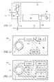
- FIG. 7illustrates a component diagram of an example configuration of coupler 20 , according to a particular embodiment.
- coupler 20includes impedance transformer 30 , capacitor 32 , base 40 , and connectors 42 and 44 .
- Impedance transformer 30 and capacitor 32operate as described above in relation to FIG. 6 .
- Base 40represents any appropriate structure for supporting the components of coupler 20 .
- base 40may represent a housing that physically surrounds one or more components of coupler 20 .
- base 40may represent a substrate upon which certain components may be positioned, such as a 1′′ ⁇ 2′′ printed circuit board.
- base 40may include one or more protective coverings.
- base 40may include coverings adapted to provide weather and/or UV protection for certain components of coupler 20 .
- base 40may represent a printed circuit board coated with a first coat of Humiseal 1A20 Polyurethane and a second coat of Humiseal 1C49 Silicone.
- Connector 42represents a conductive connector adapted to electrically connect coupler 20 to communications device 18 .
- connector 42may connect coupler 20 to communications device 18 through low-voltage communications line 26 .
- low-voltage communications line 26may represent a coaxial cable and connector 42 may represent a coaxial connector, such as a BNC connector or an F-connector.
- Connector 44represents a conductive connector adapted to electrically connect coupler 20 to surge arrester 16 .
- connector 44may connect coupler 20 to surge arrester 16 through the use of one or more conductive cables or wires.
- connector 44may connect coupler 20 to surge arrester 16 through ground post 29 on surge arrester 16 .
- connector 44may represent a conductive material with an opening adapted to accept ground post 29 of surge arrester 16 .
- connector 44may represent a metallic disk (or cylinder) with a thru-hole that is approximately 0.375-0.400 inches in diameter.
- connector 44is positioned integral to base 40 such that, in operation, base 40 with connector 44 may slide over ground post 29 of surge arrester 16 to establish a conductive contact with ground post 29 and/or a retaining nut threaded onto ground post 29 .
- impedance transformer 30 and/or capacitor 32may be electrically connected in series between connector 42 and connector 44 .
- base 40may provide the electrical coupling between components of coupler 20 .
- integrated conductors of base 40may provide the electrical coupling.
- FIG. 8illustrates a portion of an example power-line communications system 10 including an example surge arrester 16 , an example disconnect device 50 , an example parallel bypass 60 including bypass capacitor 62 , and an example coupler 20 , according to a particular embodiment.
- parallel bypass 60may conductively connect between surge arrester 16 and disconnect device 50 .
- parallel bypass 60connects to coupler 20 , which, in turn, couples to both low-voltage communications line 26 and disconnect device 50 .
- variations of coupler 20(such as coupler 120 ) may include bypass capacitor 62 . In operation, capacitor 62 may provide a low-impedance bypass around disconnect device 50 for certain frequencies.
- one or more of surge arrester 16 , disconnect device 50 , parallel bypass 60 , bypass capacitor 62 and coupler 20may be included within a single component.
- one or more of the functions provided by surge arrester 16 , disconnect device 50 , parallel bypass 60 , bypass capacitor 62 , or coupler 20may be served by multiple components.
- FIG. 9illustrates a circuit diagram of an example medium-voltage power line disconnect device 50 .
- disconnect device 50may function as a resistor 52 in parallel with an air gap 54 .
- Resistor 52may represent any component or group of components that operate to provide a resistance to an electrical current.
- resistor 52may represent a grading resistor.
- disconnect device 50may limit the transmission efficiency for communications signals between medium-voltage power lines and communications device 16 .
- FIG. 10illustrates a circuit diagram of an example medium-voltage power line disconnect device 50 with an example parallel bypass 60 including bypass capacitor 62 , according to a particular embodiment.
- Parallel bypass 60may broadly represent a circuit path in parallel with disconnect device 50 .
- parallel bypass 60may be a copper wire conductively coupled between surge arrester 16 and disconnect device 50 .
- parallel bypass 60may include capacitor 62 .
- Capacitor 62may broadly represent one or more components operable to provide capacitance for parallel bypass 60 .
- capacitor 62may represent a ceramic disk capacitor, such as a 1000 picofarad, 3 kV capacitor.
- FIG. 11illustrates a circuit diagram of a portion of an example power-line communications system 10 , including an example disconnect device 50 and an example parallel bypass 60 including bypass capacitor 62 , according to a particular embodiment.
- communications device 18is connected to neutral line 14 , through conductor 28 , and to coupler 20 .
- coupler 20is connected to surge arrester 16 through disconnect device 50 in parallel with parallel bypass 60 .
- Coupler 20may or may not include components providing an impedance matching function.
- FIG. 12illustrates a component diagram of an example configuration of coupler 120 , a variation of coupler 20 including a bypass capacitor 62 .
- coupler 120 amay include base 40 , bypass capacitor 62 , and connectors 42 , 44 , and 90 .
- Connector 90may broadly represent a connector for electrically coupling parallel bypass 60 to coupler 120 a .
- connector 90may represent any appropriate hardware for electrically coupling to parallel bypass 60 .
- capacitor 62is connected in series between connector 90 and connector 44 .
- FIG. 13illustrates a component diagram of an example configuration of coupler 120 , a variation of coupler 20 including a bypass capacitor 62 .
- coupler 120 bincludes both a bypass capacitor 62 and impedance matching components.
- coupler 120 bincludes bypass capacitor 62 , connected in series with connector 90 , and impedance transformer 30 and capacitor 32 , connected in series with connector 42 .
- coupler 120 bmay operate to couple communications device 18 to medium-voltage power line 12 with improved efficiency by bypassing disconnect device 50 and by matching impedances between medium-voltage power line 12 and communications device 18 .
- FIG. 14illustrates a portion of an example power-line communications system 10 including an example surge arrester 16 , an example disconnect device 50 , an example parallel bypass 60 , and an example coupler 120 , according to a particular embodiment.
- parallel bypass 60may conductively connect between surge arrester 16 and disconnect device 50 .
- parallel bypass 60connects to coupler 20 , which, in turn, couples to both low-voltage communications line 26 and disconnect device 50 .
- parallel bypass 60does not include bypass capacitor. Rather, in this embodiment, the bypass capacitor 62 , if any, is included as a component of coupler 120 .
- FIG. 15illustrates a circuit diagram of a portion of an example power-line communications system 10 , including an example disconnect device 50 and an example parallel bypass 60 , according to a particular embodiment.
- communications device 18is connected to neutral line 14 , through conductor 28 , and to coupler 120 .
- coupler 120is connected to surge arrester 16 through disconnect device 50 in parallel with parallel bypass 60 .
- parallel bypass 60does not include bypass capacitor. Rather, in this embodiment, the bypass capacitor 62 , if any, is included as a component of coupler 120 .
- coupler 120may include both a bypass capacitor 62 and impedance matching components.
Landscapes
- Engineering & Computer Science (AREA)
- Power Engineering (AREA)
- Computer Networks & Wireless Communication (AREA)
- Signal Processing (AREA)
- Cable Transmission Systems, Equalization Of Radio And Reduction Of Echo (AREA)
- Emergency Protection Circuit Devices (AREA)
Abstract
Description
This application claims the benefit under 35 U.S.C. § 119(e) of U.S. Provisional Application Ser. No. 60/700,038 filed Jul. 15, 2005.
This invention relates generally to communications networks and in particular to a system and method for improved coupling of communications signals to a power line.
Power systems utilize a variety of electrical devices and connectors to deliver electricity from a power station or generator to customers. Some power systems utilize a three-tiered approach that utilizes high-voltage power lines with voltages in the range from approximately 60 kV to 100 kV, medium-voltage power lines with voltages in the range from approximately 4 kV to 60 kV, and low-voltage power lines with voltages in the range from approximately 90V to 600V.
In these three-tiered power systems, high-voltage power lines typically connect a power station or generator to a substation. The substation serves a particular area such as a neighborhood and includes a transformer to step-down the voltage from high voltage to medium voltage. Typically, multiple sets of medium-voltage power lines connect the substation to local distribution transformers. The distribution transformers typically serve the customers in close proximity to the distribution transformer and step-down the voltage from medium voltage to low voltage for use by the customers.
The power lines used to deliver electricity to customers have also been used to transmit and receive communications signals. For example, power lines have been used by utility companies to transmit and receive communications signals to monitor equipment and to read meters. Power lines have also been used to provide broadband communications for customers. Various techniques have been developed to couple broadband communications signals to medium-voltage power lines. These broadband communications signals typically occupy frequencies in the 2-50 MHz region. One approach to coupling communications signals to these medium-voltage power lines is to use the intrinsic capacitance of metal oxide varistor (MOV) lightning arresters to couple a portion of the communications radio frequency signals onto medium-voltage power lines. Most MOV lightning arresters have a special device attached to the bottom of the arrester assembly to explosively disconnect the grounding wire in case of a current fault. This device usually consists of a grading resistor in parallel with an air-gap and small gunpowder charge.
In one embodiment, a device for coupling communications signals onto a medium-voltage power line includes a first connector, a second connector and one or more components. The first connector is adapted to couple to a low-voltage communications line. The second connector is adapted to couple to a surge arrester. The one or more components are operable to substantially match the impedances between the surge arrester and the low-voltage communications line.
Particular embodiments of the present invention may provide one or more technical advantages. For example, certain embodiments of the present invention may provide improved transmission and throughput of communications signals. As another example, in certain embodiments, the size and placement of the coupling device may provide for relatively quick and simple installation with little or no modifications to existing equipment. In these embodiments, such relatively quick and simple installation may allow for rapid deployment of communications coverage and/or rapid repair in the event of a localized surge or lightning strike. Certain embodiments of the present invention may provide one or more of these technical advantages at a relatively low cost.
Certain embodiments of the present invention may improve the coupling efficiency for systems utilizing MOV lightning arresters with explosive disconnect devices. These disconnect devices have been shown to limit the efficiency of communications signal transmission over medium-voltage power lines. The arrester disconnect device can cause the frequency response of a communications signal coupler to roll-off prematurely and limit or prevent the use of lower frequencies between communications devices. By bypassing this disconnect device at radio frequencies, certain embodiments of the present invention may reduce the series impedance contribution of the disconnect device and thereby reduce or eliminate this performance problem.
In addition, certain embodiments may provide one or more other technical advantages some, none, or all of which may be readily apparent to those skilled in the art from the figures, descriptions, and claims included herein.
To provide a more complete understanding of the present invention and the features and advantages thereof, reference is made to the following description taken in conjunction with the accompanying drawings, in which:
It should be understood at the outset that although example embodiments of the invention are illustrated below, the present invention may be implemented using any number of techniques, whether currently known or not. The present invention should in no way be limited to the illustrated embodiments, drawings, and techniques. Additionally, the drawings are not necessarily drawn to scale.
Medium-voltage phase line 12 represents a transmission power line operable to conduct medium-voltage electricity. In certain embodiments, medium-voltage phase line 12 may be an overhead transmission line. In particular embodiments, medium-voltage phase line 12 may conduct an alternating current (AC) of electricity between approximately 4 and 60 kilovolts. In embodiments of power-line communications system 10 includingneutral line 14,neutral line 14 may represent a power line of the same or similar structure and capability as medium-voltage phase line 12.
In operation,communications system 10 may enable one or more end-users to transmit and/or receive communications signals using medium-voltage phase lines12. In certain embodiments, communications signals are coupled to medium-voltage phase line 12 and carried to and/or from one ormore communications devices 18. In certain embodiments, the communications signals are transmitted from medium-voltage phase line 12 tocommunications device 18 using the intrinsic capacitance of a metal oxide varistor (MOV) arrester. In certain embodiments,communications system 10 may enable multiple end-users to transmit and/or receive broadband communications signals. For example, the broadband communications signals may represent upstream and/or downstream traffic at transmission rates of at least 200 Kbps.
Although, certain aspects and functions of the present invention are described in terms of receiving and/or transmitting communications signals, in certain embodiments, these functions may be reversed, as may be appropriate, without departing from the spirit and scope of the present invention.
In embodiments ofregenerator unit 18aincludingwireless access point 106,wireless access point 106 operates to transmit and/or receive wireless communications signals. Thuswireless access point 106 represents any appropriate hardware and/or controlling logic for transmitting and/or receiving wireless communications signals. In certain embodiments,wireless access point 106 may transmit and/or receive wireless communications signals using an IEEE 802.11 standard protocol. In a particular embodiment, wireless access point may be a D-Link wireless access point coupled to switch104 through the use of 10/100 base-T connectors.
In operation,regenerator unit 18areceives communications signals from medium-voltage power line 12, demodulates the received communications signals, re-modulates at least a portion of the received communications signals, and transmits the re-modulated communications signals to medium-voltage power line 12. Thus, in certain embodiments,regenerator unit 18aoperates to allow communications signals to travel greater distances along medium-voltage power line 12 by preventing excess attenuation. Accordingly,regenerator unit 18amay operate to receive communications signals from a medium-voltage power line 12, amplify the communications signals and/or filter out certain types of signal noise, and then re-transmit the communications signals back on the medium-voltage power line 12. In certain embodiments,wireless access point 106 may operate to provide wireless access to one or more wireless devices. For example,wireless access point 106 may operate to create a wireless “hot spot,” by providing wireless Internet access to one or more wireless devices. In particular embodiments,wireless access point 106 may operate to allow for monitoring and/or modifying the operation ofregenerator unit 18a.
In operation, customer-access unit 18bmay receive communications signals from a medium-voltage power line 12, demodulate the received communications signals, re-modulate at least a portion of the received communications signals, and transmit the re-modulated communications signal to a low-voltage power line.
Although customer-access unit 18bhas been described as receiving communications signals from medium-voltage power line 12 and transmitting communications signals to a low-voltage power line, customer-access unit 18bmay also receive communications signals from a low-voltage power line and transmit communications signals to medium-voltage power line 12. In certain embodiments,wireless access point 106 may operate to create a wireless “hot spot,” by providing wireless Internet access to one or more wireless devices. In particular embodiments,wireless access point 106 may operate to allow for monitoring and/or modifying the operation of customer-access unit 18b.
In operation, regenerator/customer-access-unit 18cmay operate to regenerate communications signals on a medium-voltage power line 12 and/or provide one or more customers with access tocommunications network 10. In certain embodiments, regenerator/customer-access-unit 18cmay function as either aregenerator unit 18aor a customer-access unit 18b. In a particular embodiment, regenerator/customer-access unit 18cmay function as both aregenerator unit 18aand a customer-access unit 18b. For example, regenerator/customer-access unit 18cmay receive communications signals from medium-voltage power line 12, selectively communicate a portion of the received communications signals to a low-voltage power line, and selectively communicate a portion of the received communications signals to medium-voltage power line 12. In certain embodiments, regenerator/customer-access unit 18cmay also receive wireless signals through the use of awireless access point 106. For example, wireless signals received by awireless access point 106 may include instructions for monitoring and/or modifying the operation of regenerator/customer-access unit 18c. As another example, wireless signals received bywireless access point 106 may be transmitted to a medium-voltage power line 12 by amodem 102aor may be transmitted to a low-voltage power line bymodem 102b. In certain embodiments,wireless access point 106 may operate to create a wireless “hot spot,” by providing wireless Internet access to one or more wireless devices.
In certain embodiments,coupler 20 may provide an impedance match between medium-voltage phase line12 (and/or surge arrester16) and conductor26 (and/or communications device18). For example, in certain embodiments,coupler 20 may include one or more capacitors and one or more impedance transformers to provide this impedance matching function. Further description of embodiments ofcoupler 20 including one or more capacitors and one or more impedance transformers is provided below in relation toFIG. 7 . Although, certain embodiments ofcoupler 20 are described herein as including one or more capacitors and one or more impedance transformers, in other embodiments coupler20 may include other appropriate components and/or techniques to provide this impedance matching function.
In certain embodiments, coupler20 (or variations thereof, such ascoupler 120 identified below) may provide a means for bypassing an explosive disconnect device, which may improve the coupling efficiency. Embodiments providing such bypass means are described further below in relation toFIGS. 9-15 .
In the embodiment shown,coupler 20 includes animpedance transformer 30 and acapacitor 32. As shown,conductor 34ais coupled to the non-common low-impedance winding ofimpedance transformer 30, whileconductor 34bis coupled to the common winding ofimpedance transformer 30 on both the primary and secondary. In certain embodiments,conductor 34bmay also be coupled toneutral line 14 and/or a ground connection. As shown, in certain embodiments, the non-common winding of the high-impedance side ofimpedance transformer 30 is coupled to acapacitor 32, which is coupled to surgearrester 16.
In certain embodiments, medium-voltage phase line12 (and/or surge arrester16) may have an impedance in the range from 350-450 ohms and conductor26 (and/or communications device18) may have an impedance in the range from 50-75 ohms. In certain embodiments, to match impedances,impedance transformer 30 may represent a transformer with a step-up ratio in the range from approximately 5:1 to 9:1. For example, in a particular embodiment,impedance transformer 30 may represent a transformer with a step-up ratio of approximately 8:1, such as for example a Mini Circuits T8-1 transformer. In certain embodiments,capacitor 32 may have a capacitance in the range of 0.01 to 0.1 microfarads andcapacitor 32 may have a working capacity greater than 300 volts. For example, in a particular embodiment,capacitor 32 may represent a 0.047 microfarad 600 volt coupling capacitor. Although example embodiments includingimpedance transformer 30 andcapacitor 32 have been described as having certain characteristics or ranges of characteristics, any appropriate components may be used to match (or improve the matching of) impedances within power-line communications system 10 without departing from the spirit and scope of the present invention. In certain embodiments, for example, power-line communications system 10 and/orcoupler 20 may include different connection topologies and/or different types ofimpedance transformers 30. In a particular embodiment, certain functions of the present invention may be accomplished using a transmission line transformer.
In embodiments includingimpedance transformer 30 and/orcapacitor 32,impedance transformer 30 and/orcapacitor 32 may be electrically connected in series betweenconnector 42 andconnector 44. In certain embodiments,base 40 may provide the electrical coupling between components ofcoupler 20. For example, in embodiments whereinbase 40 represents a printed circuit board, integrated conductors ofbase 40 may provide the electrical coupling.
Although the present invention has been described with several embodiments, a plenitude of changes, substitutions, variations, alterations, and modifications may be suggested to one skilled in the art, and it is intended that the invention encompass all such changes, substitutions, variations, alterations, and modifications as fall within the spirit and scope of the appended claims.
Claims (26)
1. A system for communicating signals over a medium-voltage power line, the system comprising:
a communications device comprising at least one modem; and
a coupler comprising:
a coaxial connector coupled to the communications device;
an impedance transformer electrically coupled to the coaxial connector, the impedance transformer having a step-up ratio of approximately 8:1;
a capacitor electrically coupled to the impedance transformer, the capacitor having a capacitance of approximately 0.05 microfarads;
a conductive metallic disk electrically coupled to the capacitor, the conductive metallic disk defining a substantially circular opening adapted to accept a ground post from a lightning arrester; and
a circuit board, wherein the connector, the capacitor, the impedance transformer, and the conductive disk are coupled to the circuit board.
2. A system for communicating signals on a medium-voltage power line, the system comprising:
a communications device; and
a coupler comprising:
a first connector adapted to couple to the communications device;
an impedance transformer;
a capacitor; and
a second connector defining an opening adapted to accept a ground post from a surge arrester;
wherein the impedance transformer and the capacitor are coupled between the first connector and the second connector such that signals communicated between the communications device and the surge arrester pass through the impedance transformer and the capacitor.
3. The system ofclaim 2 , wherein the first connector is adapted to couple to a coaxial cable having an impedance of approximately 50-75 ohms.
4. The system ofclaim 2 , wherein the impedance transformer provides a step-up ratio in the range from 5:1 to 9:1.
5. The system ofclaim 2 , wherein the capacitor provides a capacitance in the range from 0.01 to 0.1 microfarads.
6. The system ofclaim 2 , wherein the second connector comprises a metallic disk.
7. The system ofclaim 2 , wherein the opening has a diameter in the range from 0.25 to 0.75 inches.
8. The system ofclaim 2 , wherein:
the coupler further comprises a circuit board; and
the first connector, the capacitor, the impedance transformer, and the second connector are coupled to the circuit board.
9. A device for coupling communications signals to a medium-voltage power line, the device comprising:
a first connector adapted to couple to a low-voltage communications line;
an impedance transformer;
a capacitor; and
a second connector adapted to couple to a surge arrester;
wherein the impedance transformer and the capacitor are coupled between the first connector and the second connector such that signals communicated between the low-voltage communications line and the surge arrester pass through the impedance transformer and the capacitor.
10. The device ofclaim 9 , wherein the low-voltage communications line comprises a coaxial cable having an impedance of approximately 50-75 ohms.
11. The device ofclaim 9 , wherein the impedance transformer provides a step-up ratio in the range from 5:1 to 9:1.
12. The device ofclaim 9 , wherein the capacitor provides a capacitance in the range from 0.01 to 0.1 microfarads.
13. The system ofclaim 9 , wherein the second connector comprises a metallic disk which defines a substantially circular opening with a diameter in the range from 0.25 to 0.75 inches.
14. The device ofclaim 9 , further comprising a circuit board; wherein the first connector, the capacitor, the impedance transformer, and the second connector are coupled to the circuit board.
15. A device for coupling communications signals to a medium-voltage power line, the device comprising:
a base;
one or more electrical components;
a first connector adapted to couple to a low-voltage communications line; and
a second connector adapted to conductively couple to a surge arrester, the second connector defining a substantially circular opening adapted to accept a ground post from the surge arrester;
wherein the one or more electrical components, the first connector, and the second connector are physically coupled to the base.
16. The device ofclaim 15 , wherein the base comprises a circuit board.
17. The device ofclaim 16 , further comprising a protective coating covering at least a portion of the circuit board, the protective coating adapted to seal the at least a portion of the circuit board against moisture.
18. The device ofclaim 15 , wherein the one or more electrical components are operable to provide impedance matching.
19. The device ofclaim 15 , wherein the second connector comprises a metallic disk.
20. The device ofclaim 15 , wherein the substantially circular opening has a diameter in the range from 0.2 inches to 0.8 inches.
21. The device ofclaim 15 , wherein the substantially circular opening has a diameter of 0.4 inches.
22. A device for coupling communications signals to a medium-voltage power line, the device comprising:
a first connector adapted to couple to a low-voltage communications line;
a second connector adapted to couple to a surge arrester; and
one or more components operable to substantially match the impedances between the surge arrester and the low-voltage communications line;
wherein the one or more components are coupled between the first connector and the second connector such that signals communicated between the communications device and the surge arrester pass through the one or more components.
23. The device ofclaim 22 , wherein the one or more components comprise an impedance transformer having a step-up ratio in the range from 5:1 to 9:1 in series with a capacitor having a capacitance in the range from 0.01 to 0.1 microfarads.
24. The device ofclaim 22 , wherein the low-voltage communications line comprises a coaxial cable.
25. A method for coupling communications signals to a medium-voltage power line, the method comprising:
transmitting a communications signal:
from a signal regenerator through a low-voltage communications line;
from the low-voltage communications line through one or more components operable to increase impedance by a ratio of between 5:1 and 9:1 and to substantially match the impedances between a surge arrester and the low-voltage communications line;
from the one or more components through the surge arrester; and
from the surge arrester to a medium-voltage power line.
26. A device for coupling communications signals to a medium-voltage power line, the device comprising:
a first means for coupling to a low-voltage communications line;
a second means for coupling to a surge arrester; and
a means for substantially matching the impedances between the surge arrester and the low-voltage communications line;
wherein the means for substantially matching the impedances is coupled between the first means and the second means such that signals communicated between the low-voltage communications line and the surge arrester pass through the means for substantially matching the impedances.
Priority Applications (4)
| Application Number | Priority Date | Filing Date | Title |
|---|---|---|---|
| US11/425,271US7522812B2 (en) | 2005-07-15 | 2006-06-20 | Coupling of communications signals to a power line |
| PCT/US2006/026433WO2007011543A2 (en) | 2005-07-15 | 2006-06-30 | Improved coupling of communications signals to a power line |
| CA002614153ACA2614153A1 (en) | 2005-07-15 | 2006-06-30 | Improved coupling of communications signals to a power line |
| US12/177,322US7778514B2 (en) | 2005-07-15 | 2008-07-22 | Coupling of communications signals to a power line |
Applications Claiming Priority (2)
| Application Number | Priority Date | Filing Date | Title |
|---|---|---|---|
| US70003805P | 2005-07-15 | 2005-07-15 | |
| US11/425,271US7522812B2 (en) | 2005-07-15 | 2006-06-20 | Coupling of communications signals to a power line |
Related Child Applications (1)
| Application Number | Title | Priority Date | Filing Date |
|---|---|---|---|
| US12/177,322Continuation-In-PartUS7778514B2 (en) | 2005-07-15 | 2008-07-22 | Coupling of communications signals to a power line |
Publications (2)
| Publication Number | Publication Date |
|---|---|
| US20070014529A1 US20070014529A1 (en) | 2007-01-18 |
| US7522812B2true US7522812B2 (en) | 2009-04-21 |
Family
ID=37661730
Family Applications (1)
| Application Number | Title | Priority Date | Filing Date |
|---|---|---|---|
| US11/425,271Expired - Fee RelatedUS7522812B2 (en) | 2005-07-15 | 2006-06-20 | Coupling of communications signals to a power line |
Country Status (3)
| Country | Link |
|---|---|
| US (1) | US7522812B2 (en) |
| CA (1) | CA2614153A1 (en) |
| WO (1) | WO2007011543A2 (en) |
Cited By (170)
| Publication number | Priority date | Publication date | Assignee | Title |
|---|---|---|---|---|
| US20080100403A1 (en)* | 2006-10-26 | 2008-05-01 | Cooper Technologies Company | Communications interface accessory for power system arrester |
| US20090002094A1 (en)* | 2007-06-26 | 2009-01-01 | Radtke William O | Power Line Coupling Device and Method |
| US20090002137A1 (en)* | 2007-06-26 | 2009-01-01 | Radtke William O | Power Line Coupling Device and Method |
| US20090059484A1 (en)* | 2007-09-04 | 2009-03-05 | Brent David Allwood | Broadband over power line loom |
| US20100214122A1 (en)* | 2006-10-17 | 2010-08-26 | Helmut Belz | SYSTEM AND METHOD FOR OPERATING A SYSTEM (amended |
| US20110085647A1 (en)* | 2009-10-09 | 2011-04-14 | Hicks Iii John Alson | Methods, Systems and Products for Providing Modem Functions |
| US8897697B1 (en) | 2013-11-06 | 2014-11-25 | At&T Intellectual Property I, Lp | Millimeter-wave surface-wave communications |
| US9088153B2 (en) | 2012-09-26 | 2015-07-21 | Hubbell Incorporated | Series R-C graded gap assembly for MOV arrester |
| US9113347B2 (en) | 2012-12-05 | 2015-08-18 | At&T Intellectual Property I, Lp | Backhaul link for distributed antenna system |
| US20150349515A1 (en)* | 2014-06-02 | 2015-12-03 | Cooper Technologies Company | Electrically Insulated Tethers for Transmission Line Arresters |
| US9209902B2 (en) | 2013-12-10 | 2015-12-08 | At&T Intellectual Property I, L.P. | Quasi-optical coupler |
| US9312919B1 (en) | 2014-10-21 | 2016-04-12 | At&T Intellectual Property I, Lp | Transmission device with impairment compensation and methods for use therewith |
| US9461706B1 (en) | 2015-07-31 | 2016-10-04 | At&T Intellectual Property I, Lp | Method and apparatus for exchanging communication signals |
| US9490869B1 (en) | 2015-05-14 | 2016-11-08 | At&T Intellectual Property I, L.P. | Transmission medium having multiple cores and methods for use therewith |
| US9503189B2 (en) | 2014-10-10 | 2016-11-22 | At&T Intellectual Property I, L.P. | Method and apparatus for arranging communication sessions in a communication system |
| US9509415B1 (en) | 2015-06-25 | 2016-11-29 | At&T Intellectual Property I, L.P. | Methods and apparatus for inducing a fundamental wave mode on a transmission medium |
| US9520945B2 (en) | 2014-10-21 | 2016-12-13 | At&T Intellectual Property I, L.P. | Apparatus for providing communication services and methods thereof |
| US9525524B2 (en) | 2013-05-31 | 2016-12-20 | At&T Intellectual Property I, L.P. | Remote distributed antenna system |
| US9525210B2 (en) | 2014-10-21 | 2016-12-20 | At&T Intellectual Property I, L.P. | Guided-wave transmission device with non-fundamental mode propagation and methods for use therewith |
| US9531427B2 (en) | 2014-11-20 | 2016-12-27 | At&T Intellectual Property I, L.P. | Transmission device with mode division multiplexing and methods for use therewith |
| US9564947B2 (en) | 2014-10-21 | 2017-02-07 | At&T Intellectual Property I, L.P. | Guided-wave transmission device with diversity and methods for use therewith |
| US9577306B2 (en) | 2014-10-21 | 2017-02-21 | At&T Intellectual Property I, L.P. | Guided-wave transmission device and methods for use therewith |
| US9608740B2 (en) | 2015-07-15 | 2017-03-28 | At&T Intellectual Property I, L.P. | Method and apparatus for launching a wave mode that mitigates interference |
| US9608692B2 (en) | 2015-06-11 | 2017-03-28 | At&T Intellectual Property I, L.P. | Repeater and methods for use therewith |
| US9615269B2 (en) | 2014-10-02 | 2017-04-04 | At&T Intellectual Property I, L.P. | Method and apparatus that provides fault tolerance in a communication network |
| US9628116B2 (en) | 2015-07-14 | 2017-04-18 | At&T Intellectual Property I, L.P. | Apparatus and methods for transmitting wireless signals |
| US9628854B2 (en) | 2014-09-29 | 2017-04-18 | At&T Intellectual Property I, L.P. | Method and apparatus for distributing content in a communication network |
| US9640850B2 (en) | 2015-06-25 | 2017-05-02 | At&T Intellectual Property I, L.P. | Methods and apparatus for inducing a non-fundamental wave mode on a transmission medium |
| US9654173B2 (en) | 2014-11-20 | 2017-05-16 | At&T Intellectual Property I, L.P. | Apparatus for powering a communication device and methods thereof |
| US9653770B2 (en) | 2014-10-21 | 2017-05-16 | At&T Intellectual Property I, L.P. | Guided wave coupler, coupling module and methods for use therewith |
| US9667317B2 (en) | 2015-06-15 | 2017-05-30 | At&T Intellectual Property I, L.P. | Method and apparatus for providing security using network traffic adjustments |
| US9680670B2 (en) | 2014-11-20 | 2017-06-13 | At&T Intellectual Property I, L.P. | Transmission device with channel equalization and control and methods for use therewith |
| US9685992B2 (en) | 2014-10-03 | 2017-06-20 | At&T Intellectual Property I, L.P. | Circuit panel network and methods thereof |
| US9692101B2 (en) | 2014-08-26 | 2017-06-27 | At&T Intellectual Property I, L.P. | Guided wave couplers for coupling electromagnetic waves between a waveguide surface and a surface of a wire |
| US9705561B2 (en) | 2015-04-24 | 2017-07-11 | At&T Intellectual Property I, L.P. | Directional coupling device and methods for use therewith |
| US9705571B2 (en) | 2015-09-16 | 2017-07-11 | At&T Intellectual Property I, L.P. | Method and apparatus for use with a radio distributed antenna system |
| US9722318B2 (en) | 2015-07-14 | 2017-08-01 | At&T Intellectual Property I, L.P. | Method and apparatus for coupling an antenna to a device |
| US9729197B2 (en) | 2015-10-01 | 2017-08-08 | At&T Intellectual Property I, L.P. | Method and apparatus for communicating network management traffic over a network |
| US9735833B2 (en) | 2015-07-31 | 2017-08-15 | At&T Intellectual Property I, L.P. | Method and apparatus for communications management in a neighborhood network |
| US9742462B2 (en) | 2014-12-04 | 2017-08-22 | At&T Intellectual Property I, L.P. | Transmission medium and communication interfaces and methods for use therewith |
| US9749053B2 (en) | 2015-07-23 | 2017-08-29 | At&T Intellectual Property I, L.P. | Node device, repeater and methods for use therewith |
| US9749013B2 (en) | 2015-03-17 | 2017-08-29 | At&T Intellectual Property I, L.P. | Method and apparatus for reducing attenuation of electromagnetic waves guided by a transmission medium |
| US9748626B2 (en) | 2015-05-14 | 2017-08-29 | At&T Intellectual Property I, L.P. | Plurality of cables having different cross-sectional shapes which are bundled together to form a transmission medium |
| US9755697B2 (en) | 2014-09-15 | 2017-09-05 | At&T Intellectual Property I, L.P. | Method and apparatus for sensing a condition in a transmission medium of electromagnetic waves |
| US9762289B2 (en) | 2014-10-14 | 2017-09-12 | At&T Intellectual Property I, L.P. | Method and apparatus for transmitting or receiving signals in a transportation system |
| US9769020B2 (en) | 2014-10-21 | 2017-09-19 | At&T Intellectual Property I, L.P. | Method and apparatus for responding to events affecting communications in a communication network |
| US9769128B2 (en) | 2015-09-28 | 2017-09-19 | At&T Intellectual Property I, L.P. | Method and apparatus for encryption of communications over a network |
| US9780834B2 (en) | 2014-10-21 | 2017-10-03 | At&T Intellectual Property I, L.P. | Method and apparatus for transmitting electromagnetic waves |
| US9793951B2 (en) | 2015-07-15 | 2017-10-17 | At&T Intellectual Property I, L.P. | Method and apparatus for launching a wave mode that mitigates interference |
| US9793954B2 (en) | 2015-04-28 | 2017-10-17 | At&T Intellectual Property I, L.P. | Magnetic coupling device and methods for use therewith |
| US9793955B2 (en) | 2015-04-24 | 2017-10-17 | At&T Intellectual Property I, Lp | Passive electrical coupling device and methods for use therewith |
| US9800327B2 (en) | 2014-11-20 | 2017-10-24 | At&T Intellectual Property I, L.P. | Apparatus for controlling operations of a communication device and methods thereof |
| US9820146B2 (en) | 2015-06-12 | 2017-11-14 | At&T Intellectual Property I, L.P. | Method and apparatus for authentication and identity management of communicating devices |
| US9836957B2 (en) | 2015-07-14 | 2017-12-05 | At&T Intellectual Property I, L.P. | Method and apparatus for communicating with premises equipment |
| US9838896B1 (en) | 2016-12-09 | 2017-12-05 | At&T Intellectual Property I, L.P. | Method and apparatus for assessing network coverage |
| US9847850B2 (en) | 2014-10-14 | 2017-12-19 | At&T Intellectual Property I, L.P. | Method and apparatus for adjusting a mode of communication in a communication network |
| US9847566B2 (en) | 2015-07-14 | 2017-12-19 | At&T Intellectual Property I, L.P. | Method and apparatus for adjusting a field of a signal to mitigate interference |
| US9853342B2 (en) | 2015-07-14 | 2017-12-26 | At&T Intellectual Property I, L.P. | Dielectric transmission medium connector and methods for use therewith |
| US9860075B1 (en) | 2016-08-26 | 2018-01-02 | At&T Intellectual Property I, L.P. | Method and communication node for broadband distribution |
| US9866309B2 (en) | 2015-06-03 | 2018-01-09 | At&T Intellectual Property I, Lp | Host node device and methods for use therewith |
| US9865911B2 (en) | 2015-06-25 | 2018-01-09 | At&T Intellectual Property I, L.P. | Waveguide system for slot radiating first electromagnetic waves that are combined into a non-fundamental wave mode second electromagnetic wave on a transmission medium |
| US9871282B2 (en) | 2015-05-14 | 2018-01-16 | At&T Intellectual Property I, L.P. | At least one transmission medium having a dielectric surface that is covered at least in part by a second dielectric |
| US9871283B2 (en) | 2015-07-23 | 2018-01-16 | At&T Intellectual Property I, Lp | Transmission medium having a dielectric core comprised of plural members connected by a ball and socket configuration |
| US9876570B2 (en) | 2015-02-20 | 2018-01-23 | At&T Intellectual Property I, Lp | Guided-wave transmission device with non-fundamental mode propagation and methods for use therewith |
| US9876605B1 (en) | 2016-10-21 | 2018-01-23 | At&T Intellectual Property I, L.P. | Launcher and coupling system to support desired guided wave mode |
| US9876264B2 (en) | 2015-10-02 | 2018-01-23 | At&T Intellectual Property I, Lp | Communication system, guided wave switch and methods for use therewith |
| US9882257B2 (en) | 2015-07-14 | 2018-01-30 | At&T Intellectual Property I, L.P. | Method and apparatus for launching a wave mode that mitigates interference |
| US9882277B2 (en) | 2015-10-02 | 2018-01-30 | At&T Intellectual Property I, Lp | Communication device and antenna assembly with actuated gimbal mount |
| US9893795B1 (en) | 2016-12-07 | 2018-02-13 | At&T Intellectual Property I, Lp | Method and repeater for broadband distribution |
| US9904535B2 (en) | 2015-09-14 | 2018-02-27 | At&T Intellectual Property I, L.P. | Method and apparatus for distributing software |
| US9906269B2 (en) | 2014-09-17 | 2018-02-27 | At&T Intellectual Property I, L.P. | Monitoring and mitigating conditions in a communication network |
| US9913139B2 (en) | 2015-06-09 | 2018-03-06 | At&T Intellectual Property I, L.P. | Signal fingerprinting for authentication of communicating devices |
| US9911020B1 (en) | 2016-12-08 | 2018-03-06 | At&T Intellectual Property I, L.P. | Method and apparatus for tracking via a radio frequency identification device |
| US9912419B1 (en) | 2016-08-24 | 2018-03-06 | At&T Intellectual Property I, L.P. | Method and apparatus for managing a fault in a distributed antenna system |
| US9912027B2 (en) | 2015-07-23 | 2018-03-06 | At&T Intellectual Property I, L.P. | Method and apparatus for exchanging communication signals |
| US9912382B2 (en) | 2015-06-03 | 2018-03-06 | At&T Intellectual Property I, Lp | Network termination and methods for use therewith |
| US9917341B2 (en) | 2015-05-27 | 2018-03-13 | At&T Intellectual Property I, L.P. | Apparatus and method for launching electromagnetic waves and for modifying radial dimensions of the propagating electromagnetic waves |
| US9927517B1 (en) | 2016-12-06 | 2018-03-27 | At&T Intellectual Property I, L.P. | Apparatus and methods for sensing rainfall |
| US9948354B2 (en) | 2015-04-28 | 2018-04-17 | At&T Intellectual Property I, L.P. | Magnetic coupling device with reflective plate and methods for use therewith |
| US9948333B2 (en) | 2015-07-23 | 2018-04-17 | At&T Intellectual Property I, L.P. | Method and apparatus for wireless communications to mitigate interference |
| US9954287B2 (en) | 2014-11-20 | 2018-04-24 | At&T Intellectual Property I, L.P. | Apparatus for converting wireless signals and electromagnetic waves and methods thereof |
| US9967173B2 (en) | 2015-07-31 | 2018-05-08 | At&T Intellectual Property I, L.P. | Method and apparatus for authentication and identity management of communicating devices |
| US9973940B1 (en) | 2017-02-27 | 2018-05-15 | At&T Intellectual Property I, L.P. | Apparatus and methods for dynamic impedance matching of a guided wave launcher |
| US9991580B2 (en) | 2016-10-21 | 2018-06-05 | At&T Intellectual Property I, L.P. | Launcher and coupling system for guided wave mode cancellation |
| US9999038B2 (en) | 2013-05-31 | 2018-06-12 | At&T Intellectual Property I, L.P. | Remote distributed antenna system |
| US9997819B2 (en) | 2015-06-09 | 2018-06-12 | At&T Intellectual Property I, L.P. | Transmission medium and method for facilitating propagation of electromagnetic waves via a core |
| US9998870B1 (en) | 2016-12-08 | 2018-06-12 | At&T Intellectual Property I, L.P. | Method and apparatus for proximity sensing |
| US10009063B2 (en) | 2015-09-16 | 2018-06-26 | At&T Intellectual Property I, L.P. | Method and apparatus for use with a radio distributed antenna system having an out-of-band reference signal |
| US10009067B2 (en) | 2014-12-04 | 2018-06-26 | At&T Intellectual Property I, L.P. | Method and apparatus for configuring a communication interface |
| US10009065B2 (en) | 2012-12-05 | 2018-06-26 | At&T Intellectual Property I, L.P. | Backhaul link for distributed antenna system |
| US10009901B2 (en) | 2015-09-16 | 2018-06-26 | At&T Intellectual Property I, L.P. | Method, apparatus, and computer-readable storage medium for managing utilization of wireless resources between base stations |
| US10020587B2 (en) | 2015-07-31 | 2018-07-10 | At&T Intellectual Property I, L.P. | Radial antenna and methods for use therewith |
| US10020844B2 (en) | 2016-12-06 | 2018-07-10 | T&T Intellectual Property I, L.P. | Method and apparatus for broadcast communication via guided waves |
| US10027397B2 (en) | 2016-12-07 | 2018-07-17 | At&T Intellectual Property I, L.P. | Distributed antenna system and methods for use therewith |
| US10033107B2 (en) | 2015-07-14 | 2018-07-24 | At&T Intellectual Property I, L.P. | Method and apparatus for coupling an antenna to a device |
| US10033108B2 (en) | 2015-07-14 | 2018-07-24 | At&T Intellectual Property I, L.P. | Apparatus and methods for generating an electromagnetic wave having a wave mode that mitigates interference |
| US10044409B2 (en) | 2015-07-14 | 2018-08-07 | At&T Intellectual Property I, L.P. | Transmission medium and methods for use therewith |
| US10051483B2 (en) | 2015-10-16 | 2018-08-14 | At&T Intellectual Property I, L.P. | Method and apparatus for directing wireless signals |
| US10051629B2 (en) | 2015-09-16 | 2018-08-14 | At&T Intellectual Property I, L.P. | Method and apparatus for use with a radio distributed antenna system having an in-band reference signal |
| US10069535B2 (en) | 2016-12-08 | 2018-09-04 | At&T Intellectual Property I, L.P. | Apparatus and methods for launching electromagnetic waves having a certain electric field structure |
| US10074890B2 (en) | 2015-10-02 | 2018-09-11 | At&T Intellectual Property I, L.P. | Communication device and antenna with integrated light assembly |
| US10079661B2 (en) | 2015-09-16 | 2018-09-18 | At&T Intellectual Property I, L.P. | Method and apparatus for use with a radio distributed antenna system having a clock reference |
| US10090606B2 (en) | 2015-07-15 | 2018-10-02 | At&T Intellectual Property I, L.P. | Antenna system with dielectric array and methods for use therewith |
| US10090594B2 (en) | 2016-11-23 | 2018-10-02 | At&T Intellectual Property I, L.P. | Antenna system having structural configurations for assembly |
| US10103422B2 (en) | 2016-12-08 | 2018-10-16 | At&T Intellectual Property I, L.P. | Method and apparatus for mounting network devices |
| US10103801B2 (en) | 2015-06-03 | 2018-10-16 | At&T Intellectual Property I, L.P. | Host node device and methods for use therewith |
| US10135146B2 (en) | 2016-10-18 | 2018-11-20 | At&T Intellectual Property I, L.P. | Apparatus and methods for launching guided waves via circuits |
| US10135147B2 (en) | 2016-10-18 | 2018-11-20 | At&T Intellectual Property I, L.P. | Apparatus and methods for launching guided waves via an antenna |
| US10135145B2 (en) | 2016-12-06 | 2018-11-20 | At&T Intellectual Property I, L.P. | Apparatus and methods for generating an electromagnetic wave along a transmission medium |
| US10136434B2 (en) | 2015-09-16 | 2018-11-20 | At&T Intellectual Property I, L.P. | Method and apparatus for use with a radio distributed antenna system having an ultra-wideband control channel |
| US10139820B2 (en) | 2016-12-07 | 2018-11-27 | At&T Intellectual Property I, L.P. | Method and apparatus for deploying equipment of a communication system |
| US10142086B2 (en) | 2015-06-11 | 2018-11-27 | At&T Intellectual Property I, L.P. | Repeater and methods for use therewith |
| US10148016B2 (en) | 2015-07-14 | 2018-12-04 | At&T Intellectual Property I, L.P. | Apparatus and methods for communicating utilizing an antenna array |
| US10144036B2 (en) | 2015-01-30 | 2018-12-04 | At&T Intellectual Property I, L.P. | Method and apparatus for mitigating interference affecting a propagation of electromagnetic waves guided by a transmission medium |
| US10154493B2 (en) | 2015-06-03 | 2018-12-11 | At&T Intellectual Property I, L.P. | Network termination and methods for use therewith |
| US10170840B2 (en) | 2015-07-14 | 2019-01-01 | At&T Intellectual Property I, L.P. | Apparatus and methods for sending or receiving electromagnetic signals |
| US10168695B2 (en) | 2016-12-07 | 2019-01-01 | At&T Intellectual Property I, L.P. | Method and apparatus for controlling an unmanned aircraft |
| US10178445B2 (en) | 2016-11-23 | 2019-01-08 | At&T Intellectual Property I, L.P. | Methods, devices, and systems for load balancing between a plurality of waveguides |
| US10205655B2 (en) | 2015-07-14 | 2019-02-12 | At&T Intellectual Property I, L.P. | Apparatus and methods for communicating utilizing an antenna array and multiple communication paths |
| US10225025B2 (en) | 2016-11-03 | 2019-03-05 | At&T Intellectual Property I, L.P. | Method and apparatus for detecting a fault in a communication system |
| US10224634B2 (en) | 2016-11-03 | 2019-03-05 | At&T Intellectual Property I, L.P. | Methods and apparatus for adjusting an operational characteristic of an antenna |
| US10243270B2 (en) | 2016-12-07 | 2019-03-26 | At&T Intellectual Property I, L.P. | Beam adaptive multi-feed dielectric antenna system and methods for use therewith |
| US10243784B2 (en) | 2014-11-20 | 2019-03-26 | At&T Intellectual Property I, L.P. | System for generating topology information and methods thereof |
| US10264586B2 (en) | 2016-12-09 | 2019-04-16 | At&T Mobility Ii Llc | Cloud-based packet controller and methods for use therewith |
| US10291334B2 (en) | 2016-11-03 | 2019-05-14 | At&T Intellectual Property I, L.P. | System for detecting a fault in a communication system |
| US10291311B2 (en) | 2016-09-09 | 2019-05-14 | At&T Intellectual Property I, L.P. | Method and apparatus for mitigating a fault in a distributed antenna system |
| US10298293B2 (en) | 2017-03-13 | 2019-05-21 | At&T Intellectual Property I, L.P. | Apparatus of communication utilizing wireless network devices |
| US10305190B2 (en) | 2016-12-01 | 2019-05-28 | At&T Intellectual Property I, L.P. | Reflecting dielectric antenna system and methods for use therewith |
| US10312567B2 (en) | 2016-10-26 | 2019-06-04 | At&T Intellectual Property I, L.P. | Launcher with planar strip antenna and methods for use therewith |
| US10320586B2 (en) | 2015-07-14 | 2019-06-11 | At&T Intellectual Property I, L.P. | Apparatus and methods for generating non-interfering electromagnetic waves on an insulated transmission medium |
| US10326494B2 (en) | 2016-12-06 | 2019-06-18 | At&T Intellectual Property I, L.P. | Apparatus for measurement de-embedding and methods for use therewith |
| US10326689B2 (en) | 2016-12-08 | 2019-06-18 | At&T Intellectual Property I, L.P. | Method and system for providing alternative communication paths |
| US10340600B2 (en) | 2016-10-18 | 2019-07-02 | At&T Intellectual Property I, L.P. | Apparatus and methods for launching guided waves via plural waveguide systems |
| US10340601B2 (en) | 2016-11-23 | 2019-07-02 | At&T Intellectual Property I, L.P. | Multi-antenna system and methods for use therewith |
| US10341142B2 (en) | 2015-07-14 | 2019-07-02 | At&T Intellectual Property I, L.P. | Apparatus and methods for generating non-interfering electromagnetic waves on an uninsulated conductor |
| US10340603B2 (en) | 2016-11-23 | 2019-07-02 | At&T Intellectual Property I, L.P. | Antenna system having shielded structural configurations for assembly |
| US10340983B2 (en) | 2016-12-09 | 2019-07-02 | At&T Intellectual Property I, L.P. | Method and apparatus for surveying remote sites via guided wave communications |
| US10340573B2 (en) | 2016-10-26 | 2019-07-02 | At&T Intellectual Property I, L.P. | Launcher with cylindrical coupling device and methods for use therewith |
| US10348391B2 (en) | 2015-06-03 | 2019-07-09 | At&T Intellectual Property I, L.P. | Client node device with frequency conversion and methods for use therewith |
| US10355367B2 (en) | 2015-10-16 | 2019-07-16 | At&T Intellectual Property I, L.P. | Antenna structure for exchanging wireless signals |
| US10359749B2 (en) | 2016-12-07 | 2019-07-23 | At&T Intellectual Property I, L.P. | Method and apparatus for utilities management via guided wave communication |
| US10361489B2 (en) | 2016-12-01 | 2019-07-23 | At&T Intellectual Property I, L.P. | Dielectric dish antenna system and methods for use therewith |
| US10374316B2 (en) | 2016-10-21 | 2019-08-06 | At&T Intellectual Property I, L.P. | System and dielectric antenna with non-uniform dielectric |
| US10382976B2 (en) | 2016-12-06 | 2019-08-13 | At&T Intellectual Property I, L.P. | Method and apparatus for managing wireless communications based on communication paths and network device positions |
| US10389029B2 (en) | 2016-12-07 | 2019-08-20 | At&T Intellectual Property I, L.P. | Multi-feed dielectric antenna system with core selection and methods for use therewith |
| US10389037B2 (en) | 2016-12-08 | 2019-08-20 | At&T Intellectual Property I, L.P. | Apparatus and methods for selecting sections of an antenna array and use therewith |
| US10396887B2 (en) | 2015-06-03 | 2019-08-27 | At&T Intellectual Property I, L.P. | Client node device and methods for use therewith |
| US10411356B2 (en) | 2016-12-08 | 2019-09-10 | At&T Intellectual Property I, L.P. | Apparatus and methods for selectively targeting communication devices with an antenna array |
| US10439675B2 (en) | 2016-12-06 | 2019-10-08 | At&T Intellectual Property I, L.P. | Method and apparatus for repeating guided wave communication signals |
| US10446936B2 (en) | 2016-12-07 | 2019-10-15 | At&T Intellectual Property I, L.P. | Multi-feed dielectric antenna system and methods for use therewith |
| US10498044B2 (en) | 2016-11-03 | 2019-12-03 | At&T Intellectual Property I, L.P. | Apparatus for configuring a surface of an antenna |
| US10530505B2 (en) | 2016-12-08 | 2020-01-07 | At&T Intellectual Property I, L.P. | Apparatus and methods for launching electromagnetic waves along a transmission medium |
| US10535928B2 (en) | 2016-11-23 | 2020-01-14 | At&T Intellectual Property I, L.P. | Antenna system and methods for use therewith |
| US10547348B2 (en) | 2016-12-07 | 2020-01-28 | At&T Intellectual Property I, L.P. | Method and apparatus for switching transmission mediums in a communication system |
| US10601494B2 (en) | 2016-12-08 | 2020-03-24 | At&T Intellectual Property I, L.P. | Dual-band communication device and method for use therewith |
| US10637149B2 (en) | 2016-12-06 | 2020-04-28 | At&T Intellectual Property I, L.P. | Injection molded dielectric antenna and methods for use therewith |
| US10650940B2 (en) | 2015-05-15 | 2020-05-12 | At&T Intellectual Property I, L.P. | Transmission medium having a conductive material and methods for use therewith |
| US10665942B2 (en) | 2015-10-16 | 2020-05-26 | At&T Intellectual Property I, L.P. | Method and apparatus for adjusting wireless communications |
| US10679767B2 (en) | 2015-05-15 | 2020-06-09 | At&T Intellectual Property I, L.P. | Transmission medium having a conductive material and methods for use therewith |
| US10694379B2 (en) | 2016-12-06 | 2020-06-23 | At&T Intellectual Property I, L.P. | Waveguide system with device-based authentication and methods for use therewith |
| US10727599B2 (en) | 2016-12-06 | 2020-07-28 | At&T Intellectual Property I, L.P. | Launcher with slot antenna and methods for use therewith |
| US10755542B2 (en) | 2016-12-06 | 2020-08-25 | At&T Intellectual Property I, L.P. | Method and apparatus for surveillance via guided wave communication |
| US10777873B2 (en) | 2016-12-08 | 2020-09-15 | At&T Intellectual Property I, L.P. | Method and apparatus for mounting network devices |
| US10784670B2 (en) | 2015-07-23 | 2020-09-22 | At&T Intellectual Property I, L.P. | Antenna support for aligning an antenna |
| US10811767B2 (en) | 2016-10-21 | 2020-10-20 | At&T Intellectual Property I, L.P. | System and dielectric antenna with convex dielectric radome |
| US10819035B2 (en) | 2016-12-06 | 2020-10-27 | At&T Intellectual Property I, L.P. | Launcher with helical antenna and methods for use therewith |
| US10916969B2 (en) | 2016-12-08 | 2021-02-09 | At&T Intellectual Property I, L.P. | Method and apparatus for providing power using an inductive coupling |
| US10938108B2 (en) | 2016-12-08 | 2021-03-02 | At&T Intellectual Property I, L.P. | Frequency selective multi-feed dielectric antenna system and methods for use therewith |
| US11032819B2 (en) | 2016-09-15 | 2021-06-08 | At&T Intellectual Property I, L.P. | Method and apparatus for use with a radio distributed antenna system having a control channel reference signal |
| US11451264B2 (en)* | 2020-04-01 | 2022-09-20 | Schneider Electric Industries Sas | Wireless communications system |
Families Citing this family (9)
| Publication number | Priority date | Publication date | Assignee | Title |
|---|---|---|---|---|
| US7535685B2 (en)* | 2006-01-31 | 2009-05-19 | Amperion, Inc. | Radio frequency signal coupler, coupling system and method |
| GB2446621A (en)* | 2007-02-17 | 2008-08-20 | Inspired Gaming | Combining a Digital Data Signal (VoIP) with a mains power supply |
| WO2009055781A1 (en)* | 2007-10-25 | 2009-04-30 | Utility.Net Inc. | Out-of-band management for broadband over powerline network |
| US20090124209A1 (en)* | 2007-11-08 | 2009-05-14 | Michael Keselman | Methods and system for configuration of broadband over power lines |
| US20090125255A1 (en)* | 2007-11-08 | 2009-05-14 | Michael Keselman | Methods and apparatus for measuring voltage and voltage phase angle on bpl line |
| US20090153133A1 (en)* | 2007-12-13 | 2009-06-18 | Michael Keselman | Methods and apparatus for collecting characteristics of a power line a bpl system |
| WO2010008788A2 (en)* | 2008-06-23 | 2010-01-21 | Gigle Semiconductor, Inc. | Dual transformer communication interface |
| CN113608031B (en)* | 2021-08-04 | 2024-02-02 | 北京英瑞来科技有限公司 | Impact impedance monitoring method and device for substation lightning arrester |
| WO2024100487A1 (en)* | 2022-11-11 | 2024-05-16 | Prolec, S. A. De C. V. | Surge protective device and method, and an electric system with said protective device |
Citations (62)
| Publication number | Priority date | Publication date | Assignee | Title |
|---|---|---|---|---|
| US1730412A (en) | 1923-12-05 | 1929-10-08 | Wired Radio Inc | High-frequency broadcasting over power lines |
| US4142178A (en) | 1977-04-25 | 1979-02-27 | Westinghouse Electric Corp. | High voltage signal coupler for a distribution network power line carrier communication system |
| US4438519A (en) | 1981-05-04 | 1984-03-20 | General Electric Company | Methods, and apparatus, for transmitting high-bit-rate digital data in power line communication media having high harmonic noise content |
| US4471399A (en) | 1982-03-11 | 1984-09-11 | Westinghouse Electric Corp. | Power-line baseband communication system |
| US4845466A (en) | 1987-08-17 | 1989-07-04 | Signetics Corporation | System for high speed digital transmission in repetitive noise environment |
| US5351272A (en) | 1992-05-18 | 1994-09-27 | Abraham Karoly C | Communications apparatus and method for transmitting and receiving multiple modulated signals over electrical lines |
| US5684826A (en) | 1996-02-08 | 1997-11-04 | Acex Technologies, Inc. | RS-485 multipoint power line modem |
| US5777769A (en) | 1995-12-28 | 1998-07-07 | Lucent Technologies Inc. | Device and method for providing high speed data transfer through a drop line of a power line carrier communication system |
| US5856776A (en) | 1993-11-24 | 1999-01-05 | Remote Metering Systems, Ltd. | Method and apparatus for signal coupling at medium voltage in a power line carrier communications system |
| US5864284A (en) | 1997-03-06 | 1999-01-26 | Sanderson; Lelon Wayne | Apparatus for coupling radio-frequency signals to and from a cable of a power distribution network |
| US5892430A (en) | 1994-04-25 | 1999-04-06 | Foster-Miller, Inc. | Self-powered powerline sensor |
| US5892431A (en) | 1997-05-20 | 1999-04-06 | Alpha Technologies, Inc. | Power multiplexer for broadband communications systems |
| US5929750A (en) | 1992-10-22 | 1999-07-27 | Norweb Plc | Transmission network and filter therefor |
| US5937342A (en) | 1997-01-28 | 1999-08-10 | Dynamic Telecommunications, Inc. | Wireless local distribution system using standard power lines |
| US5949327A (en) | 1994-08-26 | 1999-09-07 | Norweb Plc | Coupling of telecommunications signals to a balanced power distribution network |
| US6037678A (en) | 1997-10-03 | 2000-03-14 | Northern Telecom Limited | Coupling communications signals to a power line |
| US6040759A (en) | 1998-02-17 | 2000-03-21 | Sanderson; Lelon Wayne | Communication system for providing broadband data services using a high-voltage cable of a power system |
| US6144292A (en) | 1992-10-22 | 2000-11-07 | Norweb Plc | Powerline communications network employing TDMA, FDMA and/or CDMA |
| US6243571B1 (en) | 1998-09-21 | 2001-06-05 | Phonex Corporation | Method and system for distribution of wireless signals for increased wireless coverage using power lines |
| US6278357B1 (en) | 1999-02-04 | 2001-08-21 | Electric Power Research Institute, Inc. | Apparatus and method for implementing digital communications on a power line |
| US6282405B1 (en) | 1992-10-22 | 2001-08-28 | Norweb Plc | Hybrid electricity and telecommunications distribution network |
| WO2001082497A1 (en) | 2000-04-19 | 2001-11-01 | Current Technologies, Llc | Method and apparatus for interfacing rf signals to medium voltage power lines |
| US20010038329A1 (en) | 2000-05-04 | 2001-11-08 | Paolo Diamanti | Coupling device for providing a communciations link for RF broadband data signals to a power line and method of installing same |
| US20010045888A1 (en) | 2000-01-20 | 2001-11-29 | Kline Paul A. | Method of isolating data in a power line communications network |
| US6396392B1 (en) | 2000-05-23 | 2002-05-28 | Wire21, Inc. | High frequency network communications over various lines |
| US6396393B2 (en) | 1999-12-28 | 2002-05-28 | Sony Corporation | Transmitting device, receiving device, and receiving method |
| US20020097953A1 (en) | 2000-12-15 | 2002-07-25 | Kline Paul A. | Interfacing fiber optic data with electrical power systems |
| US20020105413A1 (en) | 1999-12-30 | 2002-08-08 | Ambient Corporation | Inductive coupling of a data signal to a power transmission cable |
| US20020109585A1 (en) | 2001-02-15 | 2002-08-15 | Sanderson Lelon Wayne | Apparatus, method and system for range extension of a data communication signal on a high voltage cable |
| US20020171535A1 (en) | 2001-03-29 | 2002-11-21 | Yehuda Cern | Coupling broadband modems to power lines |
| US6493201B1 (en) | 2000-01-21 | 2002-12-10 | Mcgraw-Edison Company | Spark gap retrofit module for surge arrester |
| US6492897B1 (en) | 2000-08-04 | 2002-12-10 | Richard A. Mowery, Jr. | System for coupling wireless signals to and from a power transmission line communication system |
| US6496104B2 (en) | 2000-03-15 | 2002-12-17 | Current Technologies, L.L.C. | System and method for communication via power lines using ultra-short pulses |
| US20030039257A1 (en) | 2001-08-04 | 2003-02-27 | Manis Constantine N. | Network-to-network adaptor for power line communications |
| US20030054793A1 (en) | 2001-08-17 | 2003-03-20 | Manis Constantine N. | Coupling between power line and customer in power line communication system |
| US20030190110A1 (en) | 2001-02-14 | 2003-10-09 | Kline Paul A. | Method and apparatus for providing inductive coupling and decoupling of high-frequency, high-bandwidth data signals directly on and off of a high voltage power line |
| US20030210135A1 (en) | 2002-03-14 | 2003-11-13 | Ambient Corporation | Protecting medium voltage inductive coupled device from electrical transients |
| US20030224784A1 (en) | 2002-05-28 | 2003-12-04 | Amperion, Inc. | Communications system for providing broadband communications using a medium voltage cable of a power system |
| US20030228005A1 (en) | 2000-10-27 | 2003-12-11 | Lightwaves Systems, Inc. | High bandwidth data transport system |
| US20030234713A1 (en) | 2002-06-21 | 2003-12-25 | Pridmore Charles Franklin | Power line coupling device and method of using the same |
| US20040003934A1 (en) | 2002-06-24 | 2004-01-08 | Cope Leonard David | Power line coupling device and method of using the same |
| US20040056734A1 (en) | 2001-05-18 | 2004-03-25 | Davidow Clifford A. | Medium voltage signal coupling structure for last leg power grid high-speed data network |
| US20040135676A1 (en) | 2002-12-10 | 2004-07-15 | Berkman William H. | Power line communication system and method of operating the same |
| US20040142599A1 (en) | 2003-01-21 | 2004-07-22 | Cope Leonard D. | Power line coupling device and method of using the same |
| US6785532B1 (en) | 1996-08-01 | 2004-08-31 | Nortel Networks Limited | Power line communications |
| US20040223617A1 (en) | 2003-05-08 | 2004-11-11 | Corcoran Kevin F. | Power line communication device and method of using the same |
| US20040227621A1 (en) | 2000-04-14 | 2004-11-18 | Cope Leonard D. | Power line communication apparatus and method of using the same |
| US20040227622A1 (en) | 2003-05-13 | 2004-11-18 | Giannini Paul M. | Device and method for communicating data signals through multiple power line conductors |
| US20040246107A1 (en) | 2001-02-14 | 2004-12-09 | Current Technologies, L.L.C. | Power line communication system and method of using the same |
| US20050001693A1 (en) | 2003-07-03 | 2005-01-06 | Berkman William H. | Power line communication system and method of operating the same |
| US20050007241A1 (en) | 2000-01-20 | 2005-01-13 | Kline Paul A. | Method of isolating data in a power line communications network |
| US6844810B2 (en) | 2002-10-17 | 2005-01-18 | Ambient Corporation | Arrangement of a data coupler for power line communications |
| US20050017825A1 (en) | 2001-11-21 | 2005-01-27 | Ake Hansen | Method and system for high-speed communication over power line |
| US6854059B2 (en) | 2000-06-07 | 2005-02-08 | Conexant Systems, Inc. | Method and apparatus for medium access control in powerline communication network systems |
| US20050030118A1 (en)* | 2001-11-30 | 2005-02-10 | Deging Wang | Broadband access transmission network integrating the functions of electric power network, telecommunication network, tv network and internet |
| US6876289B2 (en) | 2003-05-29 | 2005-04-05 | Hubbell Incorporated | Arrester disconnector assembly having a capacitor |
| US20050076149A1 (en) | 2002-12-04 | 2005-04-07 | Macphy Technologies, Inc. | Method and apparatus for providing broadband wireless access services using the low voltage power line |
| US20050111533A1 (en) | 2003-10-15 | 2005-05-26 | Berkman William H. | Surface wave power line communications system and method |
| US20050111553A1 (en) | 2003-10-15 | 2005-05-26 | Jinwuk Seok | Fast half-pel searching method on the basis of SAD values according to integer-pel search and random variable corresponding to each macro block |
| US6965302B2 (en) | 2000-04-14 | 2005-11-15 | Current Technologies, Llc | Power line communication system and method of using the same |
| US6980089B1 (en) | 2000-08-09 | 2005-12-27 | Current Technologies, Llc | Non-intrusive coupling to shielded power cable |
| US20060290476A1 (en)* | 2005-06-28 | 2006-12-28 | International Broadband Electric Communications, Inc. | Improved Coupling of Communications Signals to a Power Line |
Family Cites Families (1)
| Publication number | Priority date | Publication date | Assignee | Title |
|---|---|---|---|---|
| US5864431A (en)* | 1997-07-07 | 1999-01-26 | Redifun Stimulation, Inc. | Method and apparatus for elimination of distortion in rear projection to curved surfaces |
- 2006
- 2006-06-20USUS11/425,271patent/US7522812B2/ennot_activeExpired - Fee Related
- 2006-06-30CACA002614153Apatent/CA2614153A1/ennot_activeAbandoned
- 2006-06-30WOPCT/US2006/026433patent/WO2007011543A2/enactiveApplication Filing
Patent Citations (72)
| Publication number | Priority date | Publication date | Assignee | Title |
|---|---|---|---|---|
| US1730412A (en) | 1923-12-05 | 1929-10-08 | Wired Radio Inc | High-frequency broadcasting over power lines |
| US4142178A (en) | 1977-04-25 | 1979-02-27 | Westinghouse Electric Corp. | High voltage signal coupler for a distribution network power line carrier communication system |
| US4438519A (en) | 1981-05-04 | 1984-03-20 | General Electric Company | Methods, and apparatus, for transmitting high-bit-rate digital data in power line communication media having high harmonic noise content |
| US4471399A (en) | 1982-03-11 | 1984-09-11 | Westinghouse Electric Corp. | Power-line baseband communication system |
| US4845466A (en) | 1987-08-17 | 1989-07-04 | Signetics Corporation | System for high speed digital transmission in repetitive noise environment |
| US5351272A (en) | 1992-05-18 | 1994-09-27 | Abraham Karoly C | Communications apparatus and method for transmitting and receiving multiple modulated signals over electrical lines |
| US5929750A (en) | 1992-10-22 | 1999-07-27 | Norweb Plc | Transmission network and filter therefor |
| US6282405B1 (en) | 1992-10-22 | 2001-08-28 | Norweb Plc | Hybrid electricity and telecommunications distribution network |
| US5933071A (en) | 1992-10-22 | 1999-08-03 | Norweb Plc | Electricity distribution and/or power transmission network and filter for telecommunication over power lines |
| US6144292A (en) | 1992-10-22 | 2000-11-07 | Norweb Plc | Powerline communications network employing TDMA, FDMA and/or CDMA |
| US5856776A (en) | 1993-11-24 | 1999-01-05 | Remote Metering Systems, Ltd. | Method and apparatus for signal coupling at medium voltage in a power line carrier communications system |
| US5892430A (en) | 1994-04-25 | 1999-04-06 | Foster-Miller, Inc. | Self-powered powerline sensor |
| US5949327A (en) | 1994-08-26 | 1999-09-07 | Norweb Plc | Coupling of telecommunications signals to a balanced power distribution network |
| US5777769A (en) | 1995-12-28 | 1998-07-07 | Lucent Technologies Inc. | Device and method for providing high speed data transfer through a drop line of a power line carrier communication system |
| US5684826A (en) | 1996-02-08 | 1997-11-04 | Acex Technologies, Inc. | RS-485 multipoint power line modem |
| US6785532B1 (en) | 1996-08-01 | 2004-08-31 | Nortel Networks Limited | Power line communications |
| US5937342A (en) | 1997-01-28 | 1999-08-10 | Dynamic Telecommunications, Inc. | Wireless local distribution system using standard power lines |
| US5864284A (en) | 1997-03-06 | 1999-01-26 | Sanderson; Lelon Wayne | Apparatus for coupling radio-frequency signals to and from a cable of a power distribution network |
| US5892431A (en) | 1997-05-20 | 1999-04-06 | Alpha Technologies, Inc. | Power multiplexer for broadband communications systems |
| US6037678A (en) | 1997-10-03 | 2000-03-14 | Northern Telecom Limited | Coupling communications signals to a power line |
| US6040759A (en) | 1998-02-17 | 2000-03-21 | Sanderson; Lelon Wayne | Communication system for providing broadband data services using a high-voltage cable of a power system |
| US6243571B1 (en) | 1998-09-21 | 2001-06-05 | Phonex Corporation | Method and system for distribution of wireless signals for increased wireless coverage using power lines |
| US6278357B1 (en) | 1999-02-04 | 2001-08-21 | Electric Power Research Institute, Inc. | Apparatus and method for implementing digital communications on a power line |
| US6396393B2 (en) | 1999-12-28 | 2002-05-28 | Sony Corporation | Transmitting device, receiving device, and receiving method |
| US6897764B2 (en)* | 1999-12-30 | 2005-05-24 | Ambient Corporation | Inductive coupling of a data signal for a power transmission cable |
| US6646447B2 (en) | 1999-12-30 | 2003-11-11 | Ambient Corporation | Identifying one of a plurality of wires of a power transmission cable |
| US20030160684A1 (en) | 1999-12-30 | 2003-08-28 | Ambient Corporation | Inductive coupling of a data signal for a power transmission cable |
| US20020105413A1 (en) | 1999-12-30 | 2002-08-08 | Ambient Corporation | Inductive coupling of a data signal to a power transmission cable |
| US6452482B1 (en) | 1999-12-30 | 2002-09-17 | Ambient Corporation | Inductive coupling of a data signal to a power transmission cable |
| US20050007241A1 (en) | 2000-01-20 | 2005-01-13 | Kline Paul A. | Method of isolating data in a power line communications network |
| US20010045888A1 (en) | 2000-01-20 | 2001-11-29 | Kline Paul A. | Method of isolating data in a power line communications network |
| US6493201B1 (en) | 2000-01-21 | 2002-12-10 | Mcgraw-Edison Company | Spark gap retrofit module for surge arrester |
| US6496104B2 (en) | 2000-03-15 | 2002-12-17 | Current Technologies, L.L.C. | System and method for communication via power lines using ultra-short pulses |
| US6965302B2 (en) | 2000-04-14 | 2005-11-15 | Current Technologies, Llc | Power line communication system and method of using the same |
| US20040227621A1 (en) | 2000-04-14 | 2004-11-18 | Cope Leonard D. | Power line communication apparatus and method of using the same |
| WO2001082497A1 (en) | 2000-04-19 | 2001-11-01 | Current Technologies, Llc | Method and apparatus for interfacing rf signals to medium voltage power lines |
| US20020002040A1 (en) | 2000-04-19 | 2002-01-03 | Kline Paul A. | Method and apparatus for interfacing RF signals to medium voltage power lines |
| US6683531B2 (en) | 2000-05-04 | 2004-01-27 | Trench Limited | Coupling device for providing a communications link for RF broadband data signals to a power line and method for installing same |
| US20010038329A1 (en) | 2000-05-04 | 2001-11-08 | Paolo Diamanti | Coupling device for providing a communciations link for RF broadband data signals to a power line and method of installing same |
| US6396392B1 (en) | 2000-05-23 | 2002-05-28 | Wire21, Inc. | High frequency network communications over various lines |
| US6854059B2 (en) | 2000-06-07 | 2005-02-08 | Conexant Systems, Inc. | Method and apparatus for medium access control in powerline communication network systems |
| US6492897B1 (en) | 2000-08-04 | 2002-12-10 | Richard A. Mowery, Jr. | System for coupling wireless signals to and from a power transmission line communication system |
| US6980089B1 (en) | 2000-08-09 | 2005-12-27 | Current Technologies, Llc | Non-intrusive coupling to shielded power cable |
| US20030228005A1 (en) | 2000-10-27 | 2003-12-11 | Lightwaves Systems, Inc. | High bandwidth data transport system |
| US20020097953A1 (en) | 2000-12-15 | 2002-07-25 | Kline Paul A. | Interfacing fiber optic data with electrical power systems |
| US20030190110A1 (en) | 2001-02-14 | 2003-10-09 | Kline Paul A. | Method and apparatus for providing inductive coupling and decoupling of high-frequency, high-bandwidth data signals directly on and off of a high voltage power line |
| US20040246107A1 (en) | 2001-02-14 | 2004-12-09 | Current Technologies, L.L.C. | Power line communication system and method of using the same |
| US20020109585A1 (en) | 2001-02-15 | 2002-08-15 | Sanderson Lelon Wayne | Apparatus, method and system for range extension of a data communication signal on a high voltage cable |
| US20020171535A1 (en) | 2001-03-29 | 2002-11-21 | Yehuda Cern | Coupling broadband modems to power lines |
| US6809633B2 (en) | 2001-03-29 | 2004-10-26 | Ambient Corporation | Coupling broadband modems to power lines |
| US20040056734A1 (en) | 2001-05-18 | 2004-03-25 | Davidow Clifford A. | Medium voltage signal coupling structure for last leg power grid high-speed data network |
| US20030039257A1 (en) | 2001-08-04 | 2003-02-27 | Manis Constantine N. | Network-to-network adaptor for power line communications |
| US20030054793A1 (en) | 2001-08-17 | 2003-03-20 | Manis Constantine N. | Coupling between power line and customer in power line communication system |
| US20050017825A1 (en) | 2001-11-21 | 2005-01-27 | Ake Hansen | Method and system for high-speed communication over power line |
| US20050030118A1 (en)* | 2001-11-30 | 2005-02-10 | Deging Wang | Broadband access transmission network integrating the functions of electric power network, telecommunication network, tv network and internet |
| US20030210135A1 (en) | 2002-03-14 | 2003-11-13 | Ambient Corporation | Protecting medium voltage inductive coupled device from electrical transients |
| US20030224784A1 (en) | 2002-05-28 | 2003-12-04 | Amperion, Inc. | Communications system for providing broadband communications using a medium voltage cable of a power system |
| US6885674B2 (en) | 2002-05-28 | 2005-04-26 | Amperion, Inc. | Communications system for providing broadband communications using a medium voltage cable of a power system |
| US20030234713A1 (en) | 2002-06-21 | 2003-12-25 | Pridmore Charles Franklin | Power line coupling device and method of using the same |
| US20040003934A1 (en) | 2002-06-24 | 2004-01-08 | Cope Leonard David | Power line coupling device and method of using the same |
| US6844810B2 (en) | 2002-10-17 | 2005-01-18 | Ambient Corporation | Arrangement of a data coupler for power line communications |
| US20050076149A1 (en) | 2002-12-04 | 2005-04-07 | Macphy Technologies, Inc. | Method and apparatus for providing broadband wireless access services using the low voltage power line |
| US20040135676A1 (en) | 2002-12-10 | 2004-07-15 | Berkman William H. | Power line communication system and method of operating the same |
| WO2004068638A2 (en) | 2003-01-21 | 2004-08-12 | Current Technologies, Llc | Power line coupling device and method of using the same |
| US20040142599A1 (en) | 2003-01-21 | 2004-07-22 | Cope Leonard D. | Power line coupling device and method of using the same |
| US20040223617A1 (en) | 2003-05-08 | 2004-11-11 | Corcoran Kevin F. | Power line communication device and method of using the same |
| US20040227622A1 (en) | 2003-05-13 | 2004-11-18 | Giannini Paul M. | Device and method for communicating data signals through multiple power line conductors |
| US6876289B2 (en) | 2003-05-29 | 2005-04-05 | Hubbell Incorporated | Arrester disconnector assembly having a capacitor |
| US20050001693A1 (en) | 2003-07-03 | 2005-01-06 | Berkman William H. | Power line communication system and method of operating the same |
| US20050111553A1 (en) | 2003-10-15 | 2005-05-26 | Jinwuk Seok | Fast half-pel searching method on the basis of SAD values according to integer-pel search and random variable corresponding to each macro block |
| US20050111533A1 (en) | 2003-10-15 | 2005-05-26 | Berkman William H. | Surface wave power line communications system and method |
| US20060290476A1 (en)* | 2005-06-28 | 2006-12-28 | International Broadband Electric Communications, Inc. | Improved Coupling of Communications Signals to a Power Line |
Non-Patent Citations (8)
| Title |
|---|
| Hubbell, "PDE(TM) Distribution Class Elbow Arresters," brochure, Hubbell Power Systems, Inc., Ohio Brass Co., Section 69, ISO 9001-94, Cert. No. 002196, ANSI/IEEE C62.11 Tested, 8 pages, Nov. 2002. |
| Notification of Transmittal of the International Search Report and the Written Opinion of the International Searching Authority for International Application No. PCT/US06/25176; 8 pages. |
| PCT, Notification of Transmittal of the International Search Report and the Written Opinion of the International Searching Authority, or the Declaration, PCT/US06/25642, 10 pages, Date Mailed Dec. 18, 2006. |
| PCT, Notification of Transmittal of the International Search Report and the Written Opinion of the International Searching Authority, or the Declaration, PCT/US06/26433, 10 Pages, Date Mailed Feb. 12, 2007. |
| PCT, PCT/US06/21983, "Notification of Transmittal of the International Search Report and the Written Opinion of the International Searching Authority, or the Declaration," 10 pages, mailed Apr. 26, 2007. |
| Zitting, et al., "A Device and Method for Enabling Communications Signals Using a Medium Voltage Power Line," U.S. Appl. No. 11/170,413, pending, 30 pages, filed Jun. 28, 2005. |
| Zitting, et al., "Coupling Communications Signals to Underground Power Lines," U.S. Appl. No. 11/426,116, pending, 30 pages, filed Jun. 23, 2006. |
| Zitting, et al., "Improved Coupling of Communications Signals to a Power Line," U.S. Appl. No. 11/425,288, pending, 30 pages, filed Jun. 20, 2006. |
Cited By (242)
| Publication number | Priority date | Publication date | Assignee | Title |
|---|---|---|---|---|
| US12362781B2 (en) | 2006-10-17 | 2025-07-15 | Sew-Eurodrive Gmbh & Co. Kg | System for transmitting information via electric lines and method for operating the system |
| US20100214122A1 (en)* | 2006-10-17 | 2010-08-26 | Helmut Belz | SYSTEM AND METHOD FOR OPERATING A SYSTEM (amended |
| US8063767B2 (en)* | 2006-10-26 | 2011-11-22 | Cooper Technologies Company | Communications interface accessory for power system arrester |
| US20080100403A1 (en)* | 2006-10-26 | 2008-05-01 | Cooper Technologies Company | Communications interface accessory for power system arrester |
| US20090002094A1 (en)* | 2007-06-26 | 2009-01-01 | Radtke William O | Power Line Coupling Device and Method |
| US20090002137A1 (en)* | 2007-06-26 | 2009-01-01 | Radtke William O | Power Line Coupling Device and Method |
| US7795994B2 (en)* | 2007-06-26 | 2010-09-14 | Current Technologies, Llc | Power line coupling device and method |
| US7876174B2 (en) | 2007-06-26 | 2011-01-25 | Current Technologies, Llc | Power line coupling device and method |
| US20090059484A1 (en)* | 2007-09-04 | 2009-03-05 | Brent David Allwood | Broadband over power line loom |
| US7858887B2 (en)* | 2007-09-04 | 2010-12-28 | Adc Gmbh | Broadband over power line loom |
| US20110085647A1 (en)* | 2009-10-09 | 2011-04-14 | Hicks Iii John Alson | Methods, Systems and Products for Providing Modem Functions |
| US8437468B2 (en) | 2009-10-09 | 2013-05-07 | At&T Intellectual Property I, L. P. | Methods, systems and products for providing modem functions |
| US9401999B2 (en) | 2009-10-09 | 2016-07-26 | At&T Intellectual Property I, L.P. | Methods, systems and products for providing modem functions |
| US9100505B2 (en) | 2009-10-09 | 2015-08-04 | At&T Intellectual Property I, L.P. | Methods, systems and products for providing modem functions |
| US9088153B2 (en) | 2012-09-26 | 2015-07-21 | Hubbell Incorporated | Series R-C graded gap assembly for MOV arrester |
| US10194437B2 (en) | 2012-12-05 | 2019-01-29 | At&T Intellectual Property I, L.P. | Backhaul link for distributed antenna system |
| US9119127B1 (en) | 2012-12-05 | 2015-08-25 | At&T Intellectual Property I, Lp | Backhaul link for distributed antenna system |
| US10009065B2 (en) | 2012-12-05 | 2018-06-26 | At&T Intellectual Property I, L.P. | Backhaul link for distributed antenna system |
| US9788326B2 (en) | 2012-12-05 | 2017-10-10 | At&T Intellectual Property I, L.P. | Backhaul link for distributed antenna system |
| US9699785B2 (en) | 2012-12-05 | 2017-07-04 | At&T Intellectual Property I, L.P. | Backhaul link for distributed antenna system |
| US9113347B2 (en) | 2012-12-05 | 2015-08-18 | At&T Intellectual Property I, Lp | Backhaul link for distributed antenna system |
| US9930668B2 (en) | 2013-05-31 | 2018-03-27 | At&T Intellectual Property I, L.P. | Remote distributed antenna system |
| US9999038B2 (en) | 2013-05-31 | 2018-06-12 | At&T Intellectual Property I, L.P. | Remote distributed antenna system |
| US9525524B2 (en) | 2013-05-31 | 2016-12-20 | At&T Intellectual Property I, L.P. | Remote distributed antenna system |
| US10051630B2 (en) | 2013-05-31 | 2018-08-14 | At&T Intellectual Property I, L.P. | Remote distributed antenna system |
| US10091787B2 (en) | 2013-05-31 | 2018-10-02 | At&T Intellectual Property I, L.P. | Remote distributed antenna system |
| US9674711B2 (en) | 2013-11-06 | 2017-06-06 | At&T Intellectual Property I, L.P. | Surface-wave communications and methods thereof |
| US8897697B1 (en) | 2013-11-06 | 2014-11-25 | At&T Intellectual Property I, Lp | Millimeter-wave surface-wave communications |
| US10098011B2 (en) | 2013-11-06 | 2018-10-09 | At&T Intellectual Property I, L.P. | Surface-wave communications and methods thereof |
| US9467870B2 (en) | 2013-11-06 | 2016-10-11 | At&T Intellectual Property I, L.P. | Surface-wave communications and methods thereof |
| US9661505B2 (en) | 2013-11-06 | 2017-05-23 | At&T Intellectual Property I, L.P. | Surface-wave communications and methods thereof |
| US9877209B2 (en) | 2013-11-06 | 2018-01-23 | At&T Intellectual Property I, L.P. | Surface-wave communications and methods thereof |
| US9042812B1 (en) | 2013-11-06 | 2015-05-26 | At&T Intellectual Property I, Lp | Surface-wave communications and methods thereof |
| US9882607B2 (en) | 2013-11-06 | 2018-01-30 | At&T Intellectual Property I, L.P. | Surface-wave communications and methods thereof |
| US9154966B2 (en) | 2013-11-06 | 2015-10-06 | At&T Intellectual Property I, Lp | Surface-wave communications and methods thereof |
| US9876584B2 (en) | 2013-12-10 | 2018-01-23 | At&T Intellectual Property I, L.P. | Quasi-optical coupler |
| US9794003B2 (en) | 2013-12-10 | 2017-10-17 | At&T Intellectual Property I, L.P. | Quasi-optical coupler |
| US9479266B2 (en) | 2013-12-10 | 2016-10-25 | At&T Intellectual Property I, L.P. | Quasi-optical coupler |
| US9209902B2 (en) | 2013-12-10 | 2015-12-08 | At&T Intellectual Property I, L.P. | Quasi-optical coupler |
| US9755420B2 (en)* | 2014-06-02 | 2017-09-05 | Cooper Technologies Company | Electrically insulated tethers for transmission line arresters |
| US20150349515A1 (en)* | 2014-06-02 | 2015-12-03 | Cooper Technologies Company | Electrically Insulated Tethers for Transmission Line Arresters |
| US10096881B2 (en) | 2014-08-26 | 2018-10-09 | At&T Intellectual Property I, L.P. | Guided wave couplers for coupling electromagnetic waves to an outer surface of a transmission medium |
| US9692101B2 (en) | 2014-08-26 | 2017-06-27 | At&T Intellectual Property I, L.P. | Guided wave couplers for coupling electromagnetic waves between a waveguide surface and a surface of a wire |
| US9755697B2 (en) | 2014-09-15 | 2017-09-05 | At&T Intellectual Property I, L.P. | Method and apparatus for sensing a condition in a transmission medium of electromagnetic waves |
| US9768833B2 (en) | 2014-09-15 | 2017-09-19 | At&T Intellectual Property I, L.P. | Method and apparatus for sensing a condition in a transmission medium of electromagnetic waves |
| US9906269B2 (en) | 2014-09-17 | 2018-02-27 | At&T Intellectual Property I, L.P. | Monitoring and mitigating conditions in a communication network |
| US10063280B2 (en) | 2014-09-17 | 2018-08-28 | At&T Intellectual Property I, L.P. | Monitoring and mitigating conditions in a communication network |
| US9628854B2 (en) | 2014-09-29 | 2017-04-18 | At&T Intellectual Property I, L.P. | Method and apparatus for distributing content in a communication network |
| US9615269B2 (en) | 2014-10-02 | 2017-04-04 | At&T Intellectual Property I, L.P. | Method and apparatus that provides fault tolerance in a communication network |
| US9973416B2 (en) | 2014-10-02 | 2018-05-15 | At&T Intellectual Property I, L.P. | Method and apparatus that provides fault tolerance in a communication network |
| US9998932B2 (en) | 2014-10-02 | 2018-06-12 | At&T Intellectual Property I, L.P. | Method and apparatus that provides fault tolerance in a communication network |
| US9685992B2 (en) | 2014-10-03 | 2017-06-20 | At&T Intellectual Property I, L.P. | Circuit panel network and methods thereof |
| US9503189B2 (en) | 2014-10-10 | 2016-11-22 | At&T Intellectual Property I, L.P. | Method and apparatus for arranging communication sessions in a communication system |
| US9866276B2 (en) | 2014-10-10 | 2018-01-09 | At&T Intellectual Property I, L.P. | Method and apparatus for arranging communication sessions in a communication system |
| US9973299B2 (en) | 2014-10-14 | 2018-05-15 | At&T Intellectual Property I, L.P. | Method and apparatus for adjusting a mode of communication in a communication network |
| US9847850B2 (en) | 2014-10-14 | 2017-12-19 | At&T Intellectual Property I, L.P. | Method and apparatus for adjusting a mode of communication in a communication network |
| US9762289B2 (en) | 2014-10-14 | 2017-09-12 | At&T Intellectual Property I, L.P. | Method and apparatus for transmitting or receiving signals in a transportation system |
| US9954286B2 (en) | 2014-10-21 | 2018-04-24 | At&T Intellectual Property I, L.P. | Guided-wave transmission device with non-fundamental mode propagation and methods for use therewith |
| US9948355B2 (en) | 2014-10-21 | 2018-04-17 | At&T Intellectual Property I, L.P. | Apparatus for providing communication services and methods thereof |
| US9912033B2 (en) | 2014-10-21 | 2018-03-06 | At&T Intellectual Property I, Lp | Guided wave coupler, coupling module and methods for use therewith |
| US9653770B2 (en) | 2014-10-21 | 2017-05-16 | At&T Intellectual Property I, L.P. | Guided wave coupler, coupling module and methods for use therewith |
| US9871558B2 (en) | 2014-10-21 | 2018-01-16 | At&T Intellectual Property I, L.P. | Guided-wave transmission device and methods for use therewith |
| US9312919B1 (en) | 2014-10-21 | 2016-04-12 | At&T Intellectual Property I, Lp | Transmission device with impairment compensation and methods for use therewith |
| US9627768B2 (en) | 2014-10-21 | 2017-04-18 | At&T Intellectual Property I, L.P. | Guided-wave transmission device with non-fundamental mode propagation and methods for use therewith |
| US9960808B2 (en) | 2014-10-21 | 2018-05-01 | At&T Intellectual Property I, L.P. | Guided-wave transmission device and methods for use therewith |
| US9577307B2 (en) | 2014-10-21 | 2017-02-21 | At&T Intellectual Property I, L.P. | Guided-wave transmission device and methods for use therewith |
| US9525210B2 (en) | 2014-10-21 | 2016-12-20 | At&T Intellectual Property I, L.P. | Guided-wave transmission device with non-fundamental mode propagation and methods for use therewith |
| US9577306B2 (en) | 2014-10-21 | 2017-02-21 | At&T Intellectual Property I, L.P. | Guided-wave transmission device and methods for use therewith |
| US9571209B2 (en) | 2014-10-21 | 2017-02-14 | At&T Intellectual Property I, L.P. | Transmission device with impairment compensation and methods for use therewith |
| US9705610B2 (en) | 2014-10-21 | 2017-07-11 | At&T Intellectual Property I, L.P. | Transmission device with impairment compensation and methods for use therewith |
| US9769020B2 (en) | 2014-10-21 | 2017-09-19 | At&T Intellectual Property I, L.P. | Method and apparatus for responding to events affecting communications in a communication network |
| US9564947B2 (en) | 2014-10-21 | 2017-02-07 | At&T Intellectual Property I, L.P. | Guided-wave transmission device with diversity and methods for use therewith |
| US9596001B2 (en) | 2014-10-21 | 2017-03-14 | At&T Intellectual Property I, L.P. | Apparatus for providing communication services and methods thereof |
| US9780834B2 (en) | 2014-10-21 | 2017-10-03 | At&T Intellectual Property I, L.P. | Method and apparatus for transmitting electromagnetic waves |
| US9876587B2 (en) | 2014-10-21 | 2018-01-23 | At&T Intellectual Property I, L.P. | Transmission device with impairment compensation and methods for use therewith |
| US9520945B2 (en) | 2014-10-21 | 2016-12-13 | At&T Intellectual Property I, L.P. | Apparatus for providing communication services and methods thereof |
| US9680670B2 (en) | 2014-11-20 | 2017-06-13 | At&T Intellectual Property I, L.P. | Transmission device with channel equalization and control and methods for use therewith |
| US9531427B2 (en) | 2014-11-20 | 2016-12-27 | At&T Intellectual Property I, L.P. | Transmission device with mode division multiplexing and methods for use therewith |
| US9544006B2 (en) | 2014-11-20 | 2017-01-10 | At&T Intellectual Property I, L.P. | Transmission device with mode division multiplexing and methods for use therewith |
| US9954287B2 (en) | 2014-11-20 | 2018-04-24 | At&T Intellectual Property I, L.P. | Apparatus for converting wireless signals and electromagnetic waves and methods thereof |
| US9800327B2 (en) | 2014-11-20 | 2017-10-24 | At&T Intellectual Property I, L.P. | Apparatus for controlling operations of a communication device and methods thereof |
| US10243784B2 (en) | 2014-11-20 | 2019-03-26 | At&T Intellectual Property I, L.P. | System for generating topology information and methods thereof |
| US9749083B2 (en) | 2014-11-20 | 2017-08-29 | At&T Intellectual Property I, L.P. | Transmission device with mode division multiplexing and methods for use therewith |
| US9742521B2 (en) | 2014-11-20 | 2017-08-22 | At&T Intellectual Property I, L.P. | Transmission device with mode division multiplexing and methods for use therewith |
| US9712350B2 (en) | 2014-11-20 | 2017-07-18 | At&T Intellectual Property I, L.P. | Transmission device with channel equalization and control and methods for use therewith |
| US9654173B2 (en) | 2014-11-20 | 2017-05-16 | At&T Intellectual Property I, L.P. | Apparatus for powering a communication device and methods thereof |
| US10009067B2 (en) | 2014-12-04 | 2018-06-26 | At&T Intellectual Property I, L.P. | Method and apparatus for configuring a communication interface |
| US9742462B2 (en) | 2014-12-04 | 2017-08-22 | At&T Intellectual Property I, L.P. | Transmission medium and communication interfaces and methods for use therewith |
| US10144036B2 (en) | 2015-01-30 | 2018-12-04 | At&T Intellectual Property I, L.P. | Method and apparatus for mitigating interference affecting a propagation of electromagnetic waves guided by a transmission medium |
| US9876571B2 (en) | 2015-02-20 | 2018-01-23 | At&T Intellectual Property I, Lp | Guided-wave transmission device with non-fundamental mode propagation and methods for use therewith |
| US9876570B2 (en) | 2015-02-20 | 2018-01-23 | At&T Intellectual Property I, Lp | Guided-wave transmission device with non-fundamental mode propagation and methods for use therewith |
| US9749013B2 (en) | 2015-03-17 | 2017-08-29 | At&T Intellectual Property I, L.P. | Method and apparatus for reducing attenuation of electromagnetic waves guided by a transmission medium |
| US9831912B2 (en) | 2015-04-24 | 2017-11-28 | At&T Intellectual Property I, Lp | Directional coupling device and methods for use therewith |
| US10224981B2 (en) | 2015-04-24 | 2019-03-05 | At&T Intellectual Property I, Lp | Passive electrical coupling device and methods for use therewith |
| US9705561B2 (en) | 2015-04-24 | 2017-07-11 | At&T Intellectual Property I, L.P. | Directional coupling device and methods for use therewith |
| US9793955B2 (en) | 2015-04-24 | 2017-10-17 | At&T Intellectual Property I, Lp | Passive electrical coupling device and methods for use therewith |
| US9793954B2 (en) | 2015-04-28 | 2017-10-17 | At&T Intellectual Property I, L.P. | Magnetic coupling device and methods for use therewith |
| US9948354B2 (en) | 2015-04-28 | 2018-04-17 | At&T Intellectual Property I, L.P. | Magnetic coupling device with reflective plate and methods for use therewith |
| US9887447B2 (en) | 2015-05-14 | 2018-02-06 | At&T Intellectual Property I, L.P. | Transmission medium having multiple cores and methods for use therewith |
| US9748626B2 (en) | 2015-05-14 | 2017-08-29 | At&T Intellectual Property I, L.P. | Plurality of cables having different cross-sectional shapes which are bundled together to form a transmission medium |
| US9871282B2 (en) | 2015-05-14 | 2018-01-16 | At&T Intellectual Property I, L.P. | At least one transmission medium having a dielectric surface that is covered at least in part by a second dielectric |
| US9490869B1 (en) | 2015-05-14 | 2016-11-08 | At&T Intellectual Property I, L.P. | Transmission medium having multiple cores and methods for use therewith |
| US10679767B2 (en) | 2015-05-15 | 2020-06-09 | At&T Intellectual Property I, L.P. | Transmission medium having a conductive material and methods for use therewith |
| US10650940B2 (en) | 2015-05-15 | 2020-05-12 | At&T Intellectual Property I, L.P. | Transmission medium having a conductive material and methods for use therewith |
| US9917341B2 (en) | 2015-05-27 | 2018-03-13 | At&T Intellectual Property I, L.P. | Apparatus and method for launching electromagnetic waves and for modifying radial dimensions of the propagating electromagnetic waves |
| US9935703B2 (en) | 2015-06-03 | 2018-04-03 | At&T Intellectual Property I, L.P. | Host node device and methods for use therewith |
| US9866309B2 (en) | 2015-06-03 | 2018-01-09 | At&T Intellectual Property I, Lp | Host node device and methods for use therewith |
| US10103801B2 (en) | 2015-06-03 | 2018-10-16 | At&T Intellectual Property I, L.P. | Host node device and methods for use therewith |
| US9912382B2 (en) | 2015-06-03 | 2018-03-06 | At&T Intellectual Property I, Lp | Network termination and methods for use therewith |
| US9967002B2 (en) | 2015-06-03 | 2018-05-08 | At&T Intellectual I, Lp | Network termination and methods for use therewith |
| US10050697B2 (en) | 2015-06-03 | 2018-08-14 | At&T Intellectual Property I, L.P. | Host node device and methods for use therewith |
| US10348391B2 (en) | 2015-06-03 | 2019-07-09 | At&T Intellectual Property I, L.P. | Client node device with frequency conversion and methods for use therewith |
| US10797781B2 (en) | 2015-06-03 | 2020-10-06 | At&T Intellectual Property I, L.P. | Client node device and methods for use therewith |
| US10396887B2 (en) | 2015-06-03 | 2019-08-27 | At&T Intellectual Property I, L.P. | Client node device and methods for use therewith |
| US9912381B2 (en) | 2015-06-03 | 2018-03-06 | At&T Intellectual Property I, Lp | Network termination and methods for use therewith |
| US10812174B2 (en) | 2015-06-03 | 2020-10-20 | At&T Intellectual Property I, L.P. | Client node device and methods for use therewith |
| US10154493B2 (en) | 2015-06-03 | 2018-12-11 | At&T Intellectual Property I, L.P. | Network termination and methods for use therewith |
| US9997819B2 (en) | 2015-06-09 | 2018-06-12 | At&T Intellectual Property I, L.P. | Transmission medium and method for facilitating propagation of electromagnetic waves via a core |
| US9913139B2 (en) | 2015-06-09 | 2018-03-06 | At&T Intellectual Property I, L.P. | Signal fingerprinting for authentication of communicating devices |
| US10142010B2 (en) | 2015-06-11 | 2018-11-27 | At&T Intellectual Property I, L.P. | Repeater and methods for use therewith |
| US10027398B2 (en) | 2015-06-11 | 2018-07-17 | At&T Intellectual Property I, Lp | Repeater and methods for use therewith |
| US10142086B2 (en) | 2015-06-11 | 2018-11-27 | At&T Intellectual Property I, L.P. | Repeater and methods for use therewith |
| US9608692B2 (en) | 2015-06-11 | 2017-03-28 | At&T Intellectual Property I, L.P. | Repeater and methods for use therewith |
| US9820146B2 (en) | 2015-06-12 | 2017-11-14 | At&T Intellectual Property I, L.P. | Method and apparatus for authentication and identity management of communicating devices |
| US9667317B2 (en) | 2015-06-15 | 2017-05-30 | At&T Intellectual Property I, L.P. | Method and apparatus for providing security using network traffic adjustments |
| US10069185B2 (en) | 2015-06-25 | 2018-09-04 | At&T Intellectual Property I, L.P. | Methods and apparatus for inducing a non-fundamental wave mode on a transmission medium |
| US10090601B2 (en) | 2015-06-25 | 2018-10-02 | At&T Intellectual Property I, L.P. | Waveguide system and methods for inducing a non-fundamental wave mode on a transmission medium |
| US9640850B2 (en) | 2015-06-25 | 2017-05-02 | At&T Intellectual Property I, L.P. | Methods and apparatus for inducing a non-fundamental wave mode on a transmission medium |
| US9787412B2 (en) | 2015-06-25 | 2017-10-10 | At&T Intellectual Property I, L.P. | Methods and apparatus for inducing a fundamental wave mode on a transmission medium |
| US9509415B1 (en) | 2015-06-25 | 2016-11-29 | At&T Intellectual Property I, L.P. | Methods and apparatus for inducing a fundamental wave mode on a transmission medium |
| US9865911B2 (en) | 2015-06-25 | 2018-01-09 | At&T Intellectual Property I, L.P. | Waveguide system for slot radiating first electromagnetic waves that are combined into a non-fundamental wave mode second electromagnetic wave on a transmission medium |
| US9882657B2 (en) | 2015-06-25 | 2018-01-30 | At&T Intellectual Property I, L.P. | Methods and apparatus for inducing a fundamental wave mode on a transmission medium |
| US10170840B2 (en) | 2015-07-14 | 2019-01-01 | At&T Intellectual Property I, L.P. | Apparatus and methods for sending or receiving electromagnetic signals |
| US9836957B2 (en) | 2015-07-14 | 2017-12-05 | At&T Intellectual Property I, L.P. | Method and apparatus for communicating with premises equipment |
| US9847566B2 (en) | 2015-07-14 | 2017-12-19 | At&T Intellectual Property I, L.P. | Method and apparatus for adjusting a field of a signal to mitigate interference |
| US10148016B2 (en) | 2015-07-14 | 2018-12-04 | At&T Intellectual Property I, L.P. | Apparatus and methods for communicating utilizing an antenna array |
| US10033108B2 (en) | 2015-07-14 | 2018-07-24 | At&T Intellectual Property I, L.P. | Apparatus and methods for generating an electromagnetic wave having a wave mode that mitigates interference |
| US9947982B2 (en) | 2015-07-14 | 2018-04-17 | At&T Intellectual Property I, Lp | Dielectric transmission medium connector and methods for use therewith |
| US9628116B2 (en) | 2015-07-14 | 2017-04-18 | At&T Intellectual Property I, L.P. | Apparatus and methods for transmitting wireless signals |
| US9929755B2 (en) | 2015-07-14 | 2018-03-27 | At&T Intellectual Property I, L.P. | Method and apparatus for coupling an antenna to a device |
| US9853342B2 (en) | 2015-07-14 | 2017-12-26 | At&T Intellectual Property I, L.P. | Dielectric transmission medium connector and methods for use therewith |
| US10044409B2 (en) | 2015-07-14 | 2018-08-07 | At&T Intellectual Property I, L.P. | Transmission medium and methods for use therewith |
| US10033107B2 (en) | 2015-07-14 | 2018-07-24 | At&T Intellectual Property I, L.P. | Method and apparatus for coupling an antenna to a device |
| US10205655B2 (en) | 2015-07-14 | 2019-02-12 | At&T Intellectual Property I, L.P. | Apparatus and methods for communicating utilizing an antenna array and multiple communication paths |
| US10341142B2 (en) | 2015-07-14 | 2019-07-02 | At&T Intellectual Property I, L.P. | Apparatus and methods for generating non-interfering electromagnetic waves on an uninsulated conductor |
| US9882257B2 (en) | 2015-07-14 | 2018-01-30 | At&T Intellectual Property I, L.P. | Method and apparatus for launching a wave mode that mitigates interference |
| US9722318B2 (en) | 2015-07-14 | 2017-08-01 | At&T Intellectual Property I, L.P. | Method and apparatus for coupling an antenna to a device |
| US10320586B2 (en) | 2015-07-14 | 2019-06-11 | At&T Intellectual Property I, L.P. | Apparatus and methods for generating non-interfering electromagnetic waves on an insulated transmission medium |
| US10090606B2 (en) | 2015-07-15 | 2018-10-02 | At&T Intellectual Property I, L.P. | Antenna system with dielectric array and methods for use therewith |
| US9793951B2 (en) | 2015-07-15 | 2017-10-17 | At&T Intellectual Property I, L.P. | Method and apparatus for launching a wave mode that mitigates interference |
| US9608740B2 (en) | 2015-07-15 | 2017-03-28 | At&T Intellectual Property I, L.P. | Method and apparatus for launching a wave mode that mitigates interference |
| US9912027B2 (en) | 2015-07-23 | 2018-03-06 | At&T Intellectual Property I, L.P. | Method and apparatus for exchanging communication signals |
| US9806818B2 (en) | 2015-07-23 | 2017-10-31 | At&T Intellectual Property I, Lp | Node device, repeater and methods for use therewith |
| US9948333B2 (en) | 2015-07-23 | 2018-04-17 | At&T Intellectual Property I, L.P. | Method and apparatus for wireless communications to mitigate interference |
| US9749053B2 (en) | 2015-07-23 | 2017-08-29 | At&T Intellectual Property I, L.P. | Node device, repeater and methods for use therewith |
| US10784670B2 (en) | 2015-07-23 | 2020-09-22 | At&T Intellectual Property I, L.P. | Antenna support for aligning an antenna |
| US10074886B2 (en) | 2015-07-23 | 2018-09-11 | At&T Intellectual Property I, L.P. | Dielectric transmission medium comprising a plurality of rigid dielectric members coupled together in a ball and socket configuration |
| US9871283B2 (en) | 2015-07-23 | 2018-01-16 | At&T Intellectual Property I, Lp | Transmission medium having a dielectric core comprised of plural members connected by a ball and socket configuration |
| US9735833B2 (en) | 2015-07-31 | 2017-08-15 | At&T Intellectual Property I, L.P. | Method and apparatus for communications management in a neighborhood network |
| US9461706B1 (en) | 2015-07-31 | 2016-10-04 | At&T Intellectual Property I, Lp | Method and apparatus for exchanging communication signals |
| US10020587B2 (en) | 2015-07-31 | 2018-07-10 | At&T Intellectual Property I, L.P. | Radial antenna and methods for use therewith |
| US9967173B2 (en) | 2015-07-31 | 2018-05-08 | At&T Intellectual Property I, L.P. | Method and apparatus for authentication and identity management of communicating devices |
| US9838078B2 (en) | 2015-07-31 | 2017-12-05 | At&T Intellectual Property I, L.P. | Method and apparatus for exchanging communication signals |
| US9904535B2 (en) | 2015-09-14 | 2018-02-27 | At&T Intellectual Property I, L.P. | Method and apparatus for distributing software |
| US10009901B2 (en) | 2015-09-16 | 2018-06-26 | At&T Intellectual Property I, L.P. | Method, apparatus, and computer-readable storage medium for managing utilization of wireless resources between base stations |
| US10136434B2 (en) | 2015-09-16 | 2018-11-20 | At&T Intellectual Property I, L.P. | Method and apparatus for use with a radio distributed antenna system having an ultra-wideband control channel |
| US9705571B2 (en) | 2015-09-16 | 2017-07-11 | At&T Intellectual Property I, L.P. | Method and apparatus for use with a radio distributed antenna system |
| US10009063B2 (en) | 2015-09-16 | 2018-06-26 | At&T Intellectual Property I, L.P. | Method and apparatus for use with a radio distributed antenna system having an out-of-band reference signal |
| US10079661B2 (en) | 2015-09-16 | 2018-09-18 | At&T Intellectual Property I, L.P. | Method and apparatus for use with a radio distributed antenna system having a clock reference |
| US10225842B2 (en) | 2015-09-16 | 2019-03-05 | At&T Intellectual Property I, L.P. | Method, device and storage medium for communications using a modulated signal and a reference signal |
| US10051629B2 (en) | 2015-09-16 | 2018-08-14 | At&T Intellectual Property I, L.P. | Method and apparatus for use with a radio distributed antenna system having an in-band reference signal |
| US10349418B2 (en) | 2015-09-16 | 2019-07-09 | At&T Intellectual Property I, L.P. | Method and apparatus for managing utilization of wireless resources via use of a reference signal to reduce distortion |
| US9769128B2 (en) | 2015-09-28 | 2017-09-19 | At&T Intellectual Property I, L.P. | Method and apparatus for encryption of communications over a network |
| US9729197B2 (en) | 2015-10-01 | 2017-08-08 | At&T Intellectual Property I, L.P. | Method and apparatus for communicating network management traffic over a network |
| US9882277B2 (en) | 2015-10-02 | 2018-01-30 | At&T Intellectual Property I, Lp | Communication device and antenna assembly with actuated gimbal mount |
| US10074890B2 (en) | 2015-10-02 | 2018-09-11 | At&T Intellectual Property I, L.P. | Communication device and antenna with integrated light assembly |
| US9876264B2 (en) | 2015-10-02 | 2018-01-23 | At&T Intellectual Property I, Lp | Communication system, guided wave switch and methods for use therewith |
| US10665942B2 (en) | 2015-10-16 | 2020-05-26 | At&T Intellectual Property I, L.P. | Method and apparatus for adjusting wireless communications |
| US10355367B2 (en) | 2015-10-16 | 2019-07-16 | At&T Intellectual Property I, L.P. | Antenna structure for exchanging wireless signals |
| US10051483B2 (en) | 2015-10-16 | 2018-08-14 | At&T Intellectual Property I, L.P. | Method and apparatus for directing wireless signals |
| US9912419B1 (en) | 2016-08-24 | 2018-03-06 | At&T Intellectual Property I, L.P. | Method and apparatus for managing a fault in a distributed antenna system |
| US9860075B1 (en) | 2016-08-26 | 2018-01-02 | At&T Intellectual Property I, L.P. | Method and communication node for broadband distribution |
| US10291311B2 (en) | 2016-09-09 | 2019-05-14 | At&T Intellectual Property I, L.P. | Method and apparatus for mitigating a fault in a distributed antenna system |
| US11032819B2 (en) | 2016-09-15 | 2021-06-08 | At&T Intellectual Property I, L.P. | Method and apparatus for use with a radio distributed antenna system having a control channel reference signal |
| US10135146B2 (en) | 2016-10-18 | 2018-11-20 | At&T Intellectual Property I, L.P. | Apparatus and methods for launching guided waves via circuits |
| US10340600B2 (en) | 2016-10-18 | 2019-07-02 | At&T Intellectual Property I, L.P. | Apparatus and methods for launching guided waves via plural waveguide systems |
| US10135147B2 (en) | 2016-10-18 | 2018-11-20 | At&T Intellectual Property I, L.P. | Apparatus and methods for launching guided waves via an antenna |
| US9991580B2 (en) | 2016-10-21 | 2018-06-05 | At&T Intellectual Property I, L.P. | Launcher and coupling system for guided wave mode cancellation |
| US9876605B1 (en) | 2016-10-21 | 2018-01-23 | At&T Intellectual Property I, L.P. | Launcher and coupling system to support desired guided wave mode |
| US10374316B2 (en) | 2016-10-21 | 2019-08-06 | At&T Intellectual Property I, L.P. | System and dielectric antenna with non-uniform dielectric |
| US10811767B2 (en) | 2016-10-21 | 2020-10-20 | At&T Intellectual Property I, L.P. | System and dielectric antenna with convex dielectric radome |
| US10312567B2 (en) | 2016-10-26 | 2019-06-04 | At&T Intellectual Property I, L.P. | Launcher with planar strip antenna and methods for use therewith |
| US10340573B2 (en) | 2016-10-26 | 2019-07-02 | At&T Intellectual Property I, L.P. | Launcher with cylindrical coupling device and methods for use therewith |
| US10225025B2 (en) | 2016-11-03 | 2019-03-05 | At&T Intellectual Property I, L.P. | Method and apparatus for detecting a fault in a communication system |
| US10291334B2 (en) | 2016-11-03 | 2019-05-14 | At&T Intellectual Property I, L.P. | System for detecting a fault in a communication system |
| US10498044B2 (en) | 2016-11-03 | 2019-12-03 | At&T Intellectual Property I, L.P. | Apparatus for configuring a surface of an antenna |
| US10224634B2 (en) | 2016-11-03 | 2019-03-05 | At&T Intellectual Property I, L.P. | Methods and apparatus for adjusting an operational characteristic of an antenna |
| US10090594B2 (en) | 2016-11-23 | 2018-10-02 | At&T Intellectual Property I, L.P. | Antenna system having structural configurations for assembly |
| US10535928B2 (en) | 2016-11-23 | 2020-01-14 | At&T Intellectual Property I, L.P. | Antenna system and methods for use therewith |
| US10178445B2 (en) | 2016-11-23 | 2019-01-08 | At&T Intellectual Property I, L.P. | Methods, devices, and systems for load balancing between a plurality of waveguides |
| US10340601B2 (en) | 2016-11-23 | 2019-07-02 | At&T Intellectual Property I, L.P. | Multi-antenna system and methods for use therewith |
| US10340603B2 (en) | 2016-11-23 | 2019-07-02 | At&T Intellectual Property I, L.P. | Antenna system having shielded structural configurations for assembly |
| US10305190B2 (en) | 2016-12-01 | 2019-05-28 | At&T Intellectual Property I, L.P. | Reflecting dielectric antenna system and methods for use therewith |
| US10361489B2 (en) | 2016-12-01 | 2019-07-23 | At&T Intellectual Property I, L.P. | Dielectric dish antenna system and methods for use therewith |
| US10727599B2 (en) | 2016-12-06 | 2020-07-28 | At&T Intellectual Property I, L.P. | Launcher with slot antenna and methods for use therewith |
| US10135145B2 (en) | 2016-12-06 | 2018-11-20 | At&T Intellectual Property I, L.P. | Apparatus and methods for generating an electromagnetic wave along a transmission medium |
| US10020844B2 (en) | 2016-12-06 | 2018-07-10 | T&T Intellectual Property I, L.P. | Method and apparatus for broadcast communication via guided waves |
| US10637149B2 (en) | 2016-12-06 | 2020-04-28 | At&T Intellectual Property I, L.P. | Injection molded dielectric antenna and methods for use therewith |
| US9927517B1 (en) | 2016-12-06 | 2018-03-27 | At&T Intellectual Property I, L.P. | Apparatus and methods for sensing rainfall |
| US10755542B2 (en) | 2016-12-06 | 2020-08-25 | At&T Intellectual Property I, L.P. | Method and apparatus for surveillance via guided wave communication |
| US10326494B2 (en) | 2016-12-06 | 2019-06-18 | At&T Intellectual Property I, L.P. | Apparatus for measurement de-embedding and methods for use therewith |
| US10694379B2 (en) | 2016-12-06 | 2020-06-23 | At&T Intellectual Property I, L.P. | Waveguide system with device-based authentication and methods for use therewith |
| US10382976B2 (en) | 2016-12-06 | 2019-08-13 | At&T Intellectual Property I, L.P. | Method and apparatus for managing wireless communications based on communication paths and network device positions |
| US10819035B2 (en) | 2016-12-06 | 2020-10-27 | At&T Intellectual Property I, L.P. | Launcher with helical antenna and methods for use therewith |
| US10439675B2 (en) | 2016-12-06 | 2019-10-08 | At&T Intellectual Property I, L.P. | Method and apparatus for repeating guided wave communication signals |
| US10243270B2 (en) | 2016-12-07 | 2019-03-26 | At&T Intellectual Property I, L.P. | Beam adaptive multi-feed dielectric antenna system and methods for use therewith |
| US10168695B2 (en) | 2016-12-07 | 2019-01-01 | At&T Intellectual Property I, L.P. | Method and apparatus for controlling an unmanned aircraft |
| US10139820B2 (en) | 2016-12-07 | 2018-11-27 | At&T Intellectual Property I, L.P. | Method and apparatus for deploying equipment of a communication system |
| US10446936B2 (en) | 2016-12-07 | 2019-10-15 | At&T Intellectual Property I, L.P. | Multi-feed dielectric antenna system and methods for use therewith |
| US10389029B2 (en) | 2016-12-07 | 2019-08-20 | At&T Intellectual Property I, L.P. | Multi-feed dielectric antenna system with core selection and methods for use therewith |
| US9893795B1 (en) | 2016-12-07 | 2018-02-13 | At&T Intellectual Property I, Lp | Method and repeater for broadband distribution |
| US10359749B2 (en) | 2016-12-07 | 2019-07-23 | At&T Intellectual Property I, L.P. | Method and apparatus for utilities management via guided wave communication |
| US10547348B2 (en) | 2016-12-07 | 2020-01-28 | At&T Intellectual Property I, L.P. | Method and apparatus for switching transmission mediums in a communication system |
| US10027397B2 (en) | 2016-12-07 | 2018-07-17 | At&T Intellectual Property I, L.P. | Distributed antenna system and methods for use therewith |
| US9998870B1 (en) | 2016-12-08 | 2018-06-12 | At&T Intellectual Property I, L.P. | Method and apparatus for proximity sensing |
| US10916969B2 (en) | 2016-12-08 | 2021-02-09 | At&T Intellectual Property I, L.P. | Method and apparatus for providing power using an inductive coupling |
| US10389037B2 (en) | 2016-12-08 | 2019-08-20 | At&T Intellectual Property I, L.P. | Apparatus and methods for selecting sections of an antenna array and use therewith |
| US10530505B2 (en) | 2016-12-08 | 2020-01-07 | At&T Intellectual Property I, L.P. | Apparatus and methods for launching electromagnetic waves along a transmission medium |
| US10326689B2 (en) | 2016-12-08 | 2019-06-18 | At&T Intellectual Property I, L.P. | Method and system for providing alternative communication paths |
| US10938108B2 (en) | 2016-12-08 | 2021-03-02 | At&T Intellectual Property I, L.P. | Frequency selective multi-feed dielectric antenna system and methods for use therewith |
| US9911020B1 (en) | 2016-12-08 | 2018-03-06 | At&T Intellectual Property I, L.P. | Method and apparatus for tracking via a radio frequency identification device |
| US10777873B2 (en) | 2016-12-08 | 2020-09-15 | At&T Intellectual Property I, L.P. | Method and apparatus for mounting network devices |
| US10601494B2 (en) | 2016-12-08 | 2020-03-24 | At&T Intellectual Property I, L.P. | Dual-band communication device and method for use therewith |
| US10411356B2 (en) | 2016-12-08 | 2019-09-10 | At&T Intellectual Property I, L.P. | Apparatus and methods for selectively targeting communication devices with an antenna array |
| US10069535B2 (en) | 2016-12-08 | 2018-09-04 | At&T Intellectual Property I, L.P. | Apparatus and methods for launching electromagnetic waves having a certain electric field structure |
| US10103422B2 (en) | 2016-12-08 | 2018-10-16 | At&T Intellectual Property I, L.P. | Method and apparatus for mounting network devices |
| US9838896B1 (en) | 2016-12-09 | 2017-12-05 | At&T Intellectual Property I, L.P. | Method and apparatus for assessing network coverage |
| US10264586B2 (en) | 2016-12-09 | 2019-04-16 | At&T Mobility Ii Llc | Cloud-based packet controller and methods for use therewith |
| US10340983B2 (en) | 2016-12-09 | 2019-07-02 | At&T Intellectual Property I, L.P. | Method and apparatus for surveying remote sites via guided wave communications |
| US9973940B1 (en) | 2017-02-27 | 2018-05-15 | At&T Intellectual Property I, L.P. | Apparatus and methods for dynamic impedance matching of a guided wave launcher |
| US10298293B2 (en) | 2017-03-13 | 2019-05-21 | At&T Intellectual Property I, L.P. | Apparatus of communication utilizing wireless network devices |
| US11451264B2 (en)* | 2020-04-01 | 2022-09-20 | Schneider Electric Industries Sas | Wireless communications system |
Also Published As
| Publication number | Publication date |
|---|---|
| WO2007011543A2 (en) | 2007-01-25 |
| CA2614153A1 (en) | 2007-01-25 |
| US20070014529A1 (en) | 2007-01-18 |
| WO2007011543A3 (en) | 2007-04-19 |
Similar Documents
| Publication | Publication Date | Title |
|---|---|---|
| US7522812B2 (en) | Coupling of communications signals to a power line | |
| US7414526B2 (en) | Coupling of communications signals to a power line | |
| US7667344B2 (en) | Coupling communications signals to underground power lines | |
| US7319717B2 (en) | Device and method for enabling communications signals using a medium voltage power line | |
| US5864284A (en) | Apparatus for coupling radio-frequency signals to and from a cable of a power distribution network | |
| US7280033B2 (en) | Surface wave power line communications system and method | |
| US8212379B2 (en) | Station communications over electrical transmission lines | |
| US7466225B2 (en) | Power line communication system and method of operating the same | |
| US7064654B2 (en) | Power line communication system and method of operating the same | |
| US6965303B2 (en) | Power line communication system and method | |
| US7072407B2 (en) | Combination power and full duplex data cable | |
| US7449991B2 (en) | Power line communications device and method | |
| US6040759A (en) | Communication system for providing broadband data services using a high-voltage cable of a power system | |
| US7046882B2 (en) | Power line communication system and method | |
| US7778514B2 (en) | Coupling of communications signals to a power line | |
| US20020109585A1 (en) | Apparatus, method and system for range extension of a data communication signal on a high voltage cable | |
| CA2515560A1 (en) | A surface wave power line communications system and method | |
| EA006177B1 (en) | Inductive coupling of a data signal to a power transmission cable | |
| CA2673162A1 (en) | Improved coupling of communications signals to a power line | |
| MX2008000613A (en) | Improved coupling of communications signals to a power line | |
| US8063767B2 (en) | Communications interface accessory for power system arrester | |
| JPH099240A (en) | Protector for branching type communication | |
| MX2007016582A (en) | A device and method for enabling communicationssignals using a medium voltage power line |
Legal Events
| Date | Code | Title | Description |
|---|---|---|---|
| AS | Assignment | Owner name:INTERNATIONAL BROADBAND ELECTRIC COMMUNICATIONS, I Free format text:ASSIGNMENT OF ASSIGNORS INTEREST;ASSIGNOR:ZITTING, MR. BRENT R.;REEL/FRAME:017818/0269 Effective date:20060531 | |
| REMI | Maintenance fee reminder mailed | ||
| LAPS | Lapse for failure to pay maintenance fees | ||
| STCH | Information on status: patent discontinuation | Free format text:PATENT EXPIRED DUE TO NONPAYMENT OF MAINTENANCE FEES UNDER 37 CFR 1.362 | |
| FP | Lapsed due to failure to pay maintenance fee | Effective date:20130421 |