US7522806B2 - Fiber optic cable distribution box - Google Patents
Fiber optic cable distribution boxDownload PDFInfo
- Publication number
- US7522806B2 US7522806B2US12/156,297US15629708AUS7522806B2US 7522806 B2US7522806 B2US 7522806B2US 15629708 AUS15629708 AUS 15629708AUS 7522806 B2US7522806 B2US 7522806B2
- Authority
- US
- United States
- Prior art keywords
- cable
- fiber optic
- distribution box
- box according
- drum region
- Prior art date
- Legal status (The legal status is an assumption and is not a legal conclusion. Google has not performed a legal analysis and makes no representation as to the accuracy of the status listed.)
- Ceased
Links
Images


Classifications
- G—PHYSICS
- G02—OPTICS
- G02B—OPTICAL ELEMENTS, SYSTEMS OR APPARATUS
- G02B6/00—Light guides; Structural details of arrangements comprising light guides and other optical elements, e.g. couplings
- G02B6/46—Processes or apparatus adapted for installing or repairing optical fibres or optical cables
- G02B6/47—Installation in buildings
- G02B6/475—Mechanical aspects of installing cables in ducts or the like for buildings
- G—PHYSICS
- G02—OPTICS
- G02B—OPTICAL ELEMENTS, SYSTEMS OR APPARATUS
- G02B6/00—Light guides; Structural details of arrangements comprising light guides and other optical elements, e.g. couplings
- G02B6/44—Mechanical structures for providing tensile strength and external protection for fibres, e.g. optical transmission cables
- G02B6/4439—Auxiliary devices
- G02B6/444—Systems or boxes with surplus lengths
- G02B6/44528—Patch-cords; Connector arrangements in the system or in the box
- G—PHYSICS
- G02—OPTICS
- G02B—OPTICAL ELEMENTS, SYSTEMS OR APPARATUS
- G02B6/00—Light guides; Structural details of arrangements comprising light guides and other optical elements, e.g. couplings
- G02B6/44—Mechanical structures for providing tensile strength and external protection for fibres, e.g. optical transmission cables
- G02B6/4439—Auxiliary devices
- G02B6/4471—Terminating devices ; Cable clamps
Definitions
- the present inventionrelates to drop or distribution boxes for managing fiber optic cables in the deployment of fiber optic networks at subscriber premises.
- MDUsmulti-dwelling units
- cable drop or distribution boxesthat are designed for mounting on walls or other structures at the premises.
- Current industry practicecalls for the boxes to have a cable entry port at the left side of the box for receiving a fiber optic cable originating from the network provider, and one or more ports at the right side of the box through which a number of fibers associated with individual subscribers at the premises are routed to connect with fibers in the provider cable.
- U.S. Pat. No. 4,976,510discloses a wall communications outlet wherein cables may enter the outlet through panels inserted at sides of the outlet, or through an opening formed in a backplate of the outlet. Two sets of sidewalls are arranged concentric with the opening in the backplate so that spare lengths of optical fibers can be placed between the sidewalls, according to the patent.
- International Application No. PCT/IT92/00055 published Nov. 11, 1993discloses a distribution device for termination of optical ribbon cables. The device has two circular grooves about which a ribbon, and fibers of the ribbon, are wound.
- the known cable boxescan be difficult and time consuming, however. Further, the known boxes are dimensioned to accommodate older types of fiber optic cables which can not tolerate bend diameters of less than three inches (76.2 mm) without impairing cable performance. Accordingly, the currently available boxes are relatively large, and are not well-suited for widespread deployment of fiber optic networks at multi-dwelling units or other kinds of premises without significant expenditures of time and labor.
- a fiber optic cable distribution boxincludes an interface compartment for interfacing a first set of fibers when routed inside the compartment, with a second set of fibers associated with a cable routed to the box.
- a drum regionextends beneath the interface compartment and includes a cylindrical wall having an axis for supporting a length of a cable wound about the wall. The drum region is constructed so that the box can turn about the axis of the cylindrical wall when a cable is paid out from the drum region.
- the interface compartment and the drum regionare arranged so that the first set of fibers inside the interface compartment, originate from an inside end portion of the cable wound about the wall of the drum region.
- FIG. 1is a perspective view of a first embodiment of a fiber optic cable distribution box according to the invention
- FIG. 2is a cross-sectional elevation view of the box of FIG. 1 , showing a cable drum region and other internal components of the box;
- FIG. 3is a view of the box of FIG. 1 as seen from the top with a cover lid removed;
- FIG. 4is a view of the box of FIG. 1 as seen from below;
- FIG. 5is a perspective view of a second embodiment of a fiber optic cable distribution box according to the invention.
- FIG. 6is a cross-sectional elevation view of the box of FIG. 5 ;
- FIG. 7is a side view of the box of FIG. 5 , showing the location of a cable strain relief device according to the invention.
- FIG. 8is an enlarged perspective view of the cable strain relief device
- FIG. 9is a view of the strain relief device in FIG. 8 with a top cover removed;
- FIG. 9Ais also a view of the strain relief device without the top cover, and shows a fiber optic cable entering one end of the device and individual fibers of the cable exiting from an opposite end of the device;
- FIG. 9Bshows the strain relief device in place in the drum region of the box
- FIG. 10is a perspective view of a third embodiment of a fiber optic cable distribution box according to the invention.
- FIG. 11is a view of the box of FIG. 10 as seen from below;
- FIG. 12is a perspective view of a connector parking area on a base of the box of FIG. 10 ;
- FIG. 13is a schematic diagram showing a number of the inventive cable boxes deployed throughout a multidwelling unit (MDU) premises, according to the invention.
- MDUmultidwelling unit
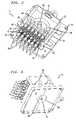
- FIG. 1shows a first embodiment of a fiber optic cable drop or distribution box 10 according to the invention.
- the box 10may be constructed of sheet metal, and/or plastics materials such as, without limitation, ABS or polycarbonate. Moisture proof seals, gaskets and the like may also be provided on or within the box 10 in a known manner if the box will be mounted outdoors at a subscriber premises.
- the box 10has a base 12 which, in the disclosed embodiment, is generally square and measures, e.g., about 6.25 inches (158.75 mm) long on each side with mounting holes 14 formed at each corner of the base.
- the box 10also has a drum region 20 that extends axially upward from a central portion of the base 12 .
- the drum region 20includes an outer cylindrical wall 22 the outside periphery of which is partially visible in FIG. 1 .
- the outside diameter of the wall 22is sufficient to allow a length of a fiber optic cable (not shown) to be wound on the drum wall 22 for storage or retention, with at least the minimum bend diameter specified for the cable.
- the outside diameter of the drum wall 22can be about 3.0 inches (76.2 mm) or less.
- An inside end portion of the cableenters a cable entry port in the drum wall while being supported over a substantially straight path by a strain relief device 24 fitted within the entry port.
- the device 24is described further below in connection with FIGS. 7 to 9B , and it guides the end portion of the cable through the cylindrical wall 22 along a line tangential to the circumference of the wall at the location of the device 24 .
- the cable distribution box 10also has an interface compartment 30 that is disposed atop the drum region 20 , and which has a peripheral side wall 31 .
- the compartment 30has a removable cover lid 32 constructed and arranged to permit an installer to access the interior of the compartment 30 from outside, and a connector guard or cover 34 that is hinged to the lid at 35 .
- the interface compartment 30is dimensioned and formed to allow a first set of optical fibers that enter the compartment 30 and originate either from a cable wound over the drum region 20 , or from a cable that enters a port in the compartment wall 31 (see FIGS. 2 and 3 ), to connect with a second set of optical fibers from another cable which fibers terminate in connectors 36 seen beneath the cover 34 in FIG.
- a number of flat fingers or tabs 38are formed to project outward from lower side edges of the compartment wall 31 , and are parallel to the base 12 .
- the tabs 38 and the base 12together serve to confine a length of cable wound about the drum wall 22 , in the region between the base and the interface compartment 30 .
- FIG. 2is a cross sectional view in elevation of the box 10 in FIG. 1
- FIG. 3is a view of the box 10 as seen from the top with the cover lid 32 removed.
- the interface compartment 30features a connector panel 40 that is supported to occupy a cut out region 41 in the compartment sidewall 31 .
- a number of optical connector adapters 42are mounted to extend through corresponding openings in the panel 40 , and the adapters 42 operate to couple the fiber optic connectors 36 at the external side of the panel 40 , with corresponding connectors 44 at the internal side of the panel.
- the panel 40is mounted in the sidewall 31 so that it can be easily removed and exchanged with another panel of the same dimensions but in which adapters of a different type are mounted.
- the panel 40may be slid in or out of vertical channels 43 formed at both ends of the sidewall cut out region 41 .
- a desired panel 40may then be selected from among a number of different panels having adapters 42 which accommodate, for example, type LC, SC, FC, ST, MPO, or type MPX connectors, depending on the type of cable connectors used at a given deployment.
- optical fibers routed into the interface compartment 30may originate from the inside end portion of a cable wound over the drum region 20 and which passes through the drum wall 22 via the strain relief device 24 .
- the fibersare routed through an annular fiber routing region 46 that extends between the outer cylindrical wall 22 , and an inner cylindrical wall 48 of the drum region which wall 48 is formed radially inward of the outer wall 22 .
- the strain relief device 24 and the dimensions of the annular fiber routing region 46are such that individual optical fibers will not be subject to a bend diameter less than that specified for the fibers before entering the interface compartment 30 and terminating in the connectors 44 .
- the inner wall 48may have an outside diameter as small as 0.7874 inches (20 mm), and the mean diameter of the fiber routing region 46 may only be about 2.0 inches (50.8 mm).
- the sidewall 31 of the interface compartment 30also has a cable entry or pass through port 50 ( FIGS. 2 & 3 ) in a rear section of the wall 31 for receiving an outside fiber optic cable or cable assembly (not shown) whose fibers are to be coupled with those fibers terminated by the connectors 36 .
- the cable entry port 50may be provided in the form of a large opening through a portion of an alternate connector panel 40 (not shown).
- the fibers of the cable entering the rear port 50may be routed directly to corresponding ones of the connectors 44 with little, if any, bending whatsoever.
- multifiber connectorssuch as type MPO in the connector panel 40 enables the box 10 to act as an aggregation box.
- multiple cables originating from other like boxes at different levels of a multi-dwelling unitmay enter the rear port 50 of the interface compartment 30 , to connect via the MPO connectors with a single cable routed to the box from an alternate location, e.g., the basement of the MDU. See FIG. 13 and related text below.
- the rear cable entry port 50is preferably kept closed by a plug 52 .
- FIG. 4is a bottom view of the cable box 10 of FIG. 1 .
- a cylindrical tube 60is formed with a central axial passage 62 .
- the tube 60extends axially between a top end of the tube 60 that fits through a clearance opening in the cover lid 32 to lie flush with the lid's top surface as shown in FIG. 1 , and a bottom end of the tube where the tube passage 62 opens beneath the base 12 as seen in FIG. 4 .
- the axis of the tube passage 62coincides with the axis of the outer cylindrical wall 22 of the drum region 20 .
- the tube 60extends above and below the center of a wall 63 that closes an upper axial end of the inner cylindrical wall 48 , as seen in FIG. 2 .
- the diameter of the central passage 62 in the tube 60is preferably sufficient to allow a long narrow tool such as a screwdriver shaft, bolt or other payoff mandrel, to be inserted through the passage from above or below the box 10 so that the tool will act as a spindle about which the box 10 can turn freely.
- This constructionallows a single worker easily to pay out a cable wound on the drum region 20 , as may be necessary for a network deployment at a MDU. For example, while holding the handle of an inserted screwdriver in one hand, the worker can use his or her other hand to pull and unwind a desired length of the cable from the drum region 20 while the box 10 is free to turn about the screwdriver shaft.
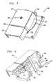
- FIGS. 5 to 7show a second embodiment of a cable distribution box 200 according to the invention.
- the box 200has a single piece cover lid 232 with an integrated hinge 235 for a connector guard or cover 234 .
- a side wall 231 of an interface compartment 230has a continuous circular disk flange 204 that extends radially outward beneath the compartment 230 , parallel to a base 212 of the box.
- the flange 204 and the base 212together serve to confine a length of fiber optic cable wound on the outer cylindrical wall 222 , within the region between the flange 204 and the base 212 .
- an inside end portion of the cableis guided by a strain relief device 224 to enter an annular fiber routing region 246 inside the box 200 , over a substantially straight path tangential to the circumference of the wall 222 at the location of the device 224 .
- the base 212 of the box 200may be formed as a separate piece that is fastened to the bottom of the drum region 220 by, e.g., screws or other fasteners that are formed to engage collars 206 fixed at the bottom of the annular fiber routing region 246 .
- FIG. 8is an enlarged, perspective view of the strain relief device 224 which corresponds to the strain relief device 24 provided in the box 10 in FIG. 1 .
- the strain relief device 224is comprised of an arcuately shaped device body 208 with a generally U-shaped cross section having an outer side wall 224 a , an inner side wall 224 b , a base wall 224 c , and a cover 209 that fits atop and extends between the side walls 224 a , 224 b of the device.
- the outer side wall 224 ahas an opening 226 at one end of the device 224 for receiving the inner end portion of, e.g., a flat ribbon fiber optic cable 260 wound on the outer cylindrical wall 222 of the drum region 220 .
- An opening 228 at the opposite end of the device 224allows individual fibers of the cable to exit from the device and to enter the fiber routing region 246 of the box 200 , preferably after each fiber is protected with, for example, a commercially available 900 ⁇ m sleeve.
- the cable 260 and its individual fibersare guided over a substantially straight path between the device openings 226 , 228 , with the aid of a pair of parallel fingers or guides 211 that project upward from the base wall 224 c of the device 224 as seen in FIGS. 9 and 9A .
- outer jacketingis stripped away from the end portion of the cable 260 , lengths of an arimid or Kevlar® yarn that surrounds the cable fibers and serves as a reinforcing or strength material for the cable, are wrapped about and secured to the guides 211 with an epoxy or other suitable adhesive.
- the inside end portion of the cable 260 and its individual fiberspass tangentially with respect to the outer cylindrical wall 222 through the cable entry port 225 in the wall, and into the annular fiber routing region 246 of the box 200 . Because the yarn surrounding the fibers is anchored to the guides 211 of the strain relief device 224 , any force applied externally to the cable 260 when the cable is being wound on or off the outer cylindrical wall 222 of the drum region, will be transferred to the wall 222 in which the device 224 is fixed rather than to the fibers themselves.
- FIGS. 10 to 12show a third embodiment of a cable distribution box 300 according to the invention.
- the box 300features an integral splice compartment 308 in its base 312 , a connector parking area 313 , and a number of security latch holes 315 .
- Typical MDU cable distribution box installationshave single fiber breakouts that egress from the box, wherein each breakout is associated with a corresponding living unit of the premises where the box is installed.
- Single fiber cables from each living unitare often routed to a box without a terminating connector.
- the bare ends of these cablescan be terminated at the box in various ways.
- single ended fiber pigtailscan be spliced within the box so that splice sleeves are housed in a common space. This requires a chamber or compartment to house the splice in order to prevent damage and to manage fiber slack.
- Alternativesmay include mechanical splicing of the pigtails, which would require a similar chamber or housing.
- the individual single fiber cablesmay also be terminated directly with a field installable connector, thus obviating the need for a splice chamber.
- the box 300has an integrated splice chamber or compartment 308 attached or formed underneath the base 312 , including a splice tray 309 mounted inside the base.
- the splice tray 309may be fixed within the box 300 , or affixed directly to a wall. In either case, the box 300 may be installed over the splice compartment 308 . Pigtails or terminated ends can then enter or exit a lower section of the compartment through corresponding clearance notches 311 that are cut in a side wall of the base 312 .
- the connector parking area or block 313allows terminated fiber ends to be stored while not in use.
- the block 313is constructed and dimensioned to receive and secure a selected one of a number of different commercially available connector parking strips 307 (e.g., type SC) in the block 313 . This feature enables the future use of alternate connector types without having to replace the box 300 , but at the same time allows installers to forego parking
- latch or security holes 315may be formed through corresponding feet on the hinged cover lid 332 .
- the latch holes 315allow the end user to utilize a number of safety lockout methods. For example, one hole 315 can be used with a standard plunger type latching mechanism simply to keep the lid closed. Other holes 315 can be used to receive wire ties, lockout tags, or other security locks.
- FIG. 13illustrates an example of a fiber optic network deployment at a multi-dwelling unit 400 .
- a number of the inventive distribution boxesfor example, the box 10 of FIGS. 1 to 4 , are mounted at corresponding locations in the MDU 400 , for example, above a drop ceiling on each floor 414 of the MDU.
- Optical fibers 416 corresponding to network subscribers on a given floor 414are terminated in the connectors 36 which, in turn, are connected to the adapters 42 on the external side of the box panel 40 .
- Each of the subscriber fibers 416is connected with a corresponding fiber in a cable 418 associated with the box 10 in the ceiling of the subscriber's floor.
- the cable 418may be wound initially about the drum region 20 of the box 10 , to be partially or fully unwound later for routing to another box 10 that serves as an “aggregation” box which is located, e.g, between a basement 420 and a roof 422 of the MDU 400 .
- the fibers of the cable 418are terminated in the connectors 44 which, in turn, are connected to the adapters 42 on the internal side of the box connector panel 40 .
- each one of the cables 418 containing subscriber fibers from each floor of the MDU 400enters the aggregation box through its rear pass through port 50 or a faceplate port.
- the fibers of each cable 418may be routed inside the box with little if any bending to connect via a multi-fiber connector 44 with a corresponding adapter 42 on the internal side of the box panel 40 .
- a main fiber optic cable 424 serving all subscribers in the MDU 400is routed between a cable entry box 426 in the basement 420 , and the aggregation box 10 in which the main cable fibers connect to the adapters 42 on the external side of the box panel 40 via multifiber connectors 36 .
- a network provider cable 430is routed to the entry box 426 from outside the MDU 400 , and fibers of the cable 430 are connected to corresponding subscriber fibers of the cable 424 inside the entry box 426 .
- An axial drum regionthat provides for external cable storage and keeps internal fiber routing within safe bending limits.
- a central through tubethat facilitates pay-off of cable wound externally on the drum region, with the use of a common tool such as a screwdriver.
Landscapes
- Physics & Mathematics (AREA)
- General Physics & Mathematics (AREA)
- Optics & Photonics (AREA)
- Engineering & Computer Science (AREA)
- Civil Engineering (AREA)
- Structural Engineering (AREA)
- Light Guides In General And Applications Therefor (AREA)
Abstract
Description
Claims (15)
Priority Applications (5)
| Application Number | Priority Date | Filing Date | Title |
|---|---|---|---|
| US12/156,297US7522806B2 (en) | 2007-01-13 | 2008-05-30 | Fiber optic cable distribution box |
| US13/091,851USRE45153E1 (en) | 2007-01-13 | 2011-04-21 | Fiber optic cable distribution box |
| US14/492,970USRE46255E1 (en) | 2007-01-13 | 2014-09-22 | Fiber optic cable distribution box |
| US15/390,085USRE48063E1 (en) | 2007-01-13 | 2016-12-23 | Fiber optic cable distribution box |
| US16/907,621USRE49385E1 (en) | 2007-01-13 | 2020-06-22 | Fiber optic cable distribution box |
Applications Claiming Priority (3)
| Application Number | Priority Date | Filing Date | Title |
|---|---|---|---|
| US88016907P | 2007-01-13 | 2007-01-13 | |
| US11/728,785US7400814B1 (en) | 2007-01-13 | 2007-03-27 | Wall-mountable optical fiber and cable management apparatus |
| US12/156,297US7522806B2 (en) | 2007-01-13 | 2008-05-30 | Fiber optic cable distribution box |
Related Parent Applications (4)
| Application Number | Title | Priority Date | Filing Date |
|---|---|---|---|
| US11/728,785ContinuationUS7400814B1 (en) | 2007-01-13 | 2007-03-27 | Wall-mountable optical fiber and cable management apparatus |
| US13/091,851ContinuationUSRE45153E1 (en) | 2007-01-13 | 2011-04-21 | Fiber optic cable distribution box |
| US14/492,970ContinuationUSRE46255E1 (en) | 2007-01-13 | 2014-09-22 | Fiber optic cable distribution box |
| US15/390,085ContinuationUSRE48063E1 (en) | 2007-01-13 | 2016-12-23 | Fiber optic cable distribution box |
Related Child Applications (4)
| Application Number | Title | Priority Date | Filing Date |
|---|---|---|---|
| US13/091,851ReissueUSRE45153E1 (en) | 2007-01-13 | 2011-04-21 | Fiber optic cable distribution box |
| US14/492,970ReissueUSRE46255E1 (en) | 2007-01-13 | 2014-09-22 | Fiber optic cable distribution box |
| US15/390,085ReissueUSRE48063E1 (en) | 2007-01-13 | 2016-12-23 | Fiber optic cable distribution box |
| US16/907,621ReissueUSRE49385E1 (en) | 2007-01-13 | 2020-06-22 | Fiber optic cable distribution box |
Publications (2)
| Publication Number | Publication Date |
|---|---|
| US20080273854A1 US20080273854A1 (en) | 2008-11-06 |
| US7522806B2true US7522806B2 (en) | 2009-04-21 |
Family
ID=39110481
Family Applications (6)
| Application Number | Title | Priority Date | Filing Date |
|---|---|---|---|
| US11/728,785ActiveUS7400814B1 (en) | 2007-01-13 | 2007-03-27 | Wall-mountable optical fiber and cable management apparatus |
| US12/156,297CeasedUS7522806B2 (en) | 2007-01-13 | 2008-05-30 | Fiber optic cable distribution box |
| US13/091,851ActiveUSRE45153E1 (en) | 2007-01-13 | 2011-04-21 | Fiber optic cable distribution box |
| US14/492,970ActiveUSRE46255E1 (en) | 2007-01-13 | 2014-09-22 | Fiber optic cable distribution box |
| US15/390,085ActiveUSRE48063E1 (en) | 2007-01-13 | 2016-12-23 | Fiber optic cable distribution box |
| US16/907,621ActiveUSRE49385E1 (en) | 2007-01-13 | 2020-06-22 | Fiber optic cable distribution box |
Family Applications Before (1)
| Application Number | Title | Priority Date | Filing Date |
|---|---|---|---|
| US11/728,785ActiveUS7400814B1 (en) | 2007-01-13 | 2007-03-27 | Wall-mountable optical fiber and cable management apparatus |
Family Applications After (4)
| Application Number | Title | Priority Date | Filing Date |
|---|---|---|---|
| US13/091,851ActiveUSRE45153E1 (en) | 2007-01-13 | 2011-04-21 | Fiber optic cable distribution box |
| US14/492,970ActiveUSRE46255E1 (en) | 2007-01-13 | 2014-09-22 | Fiber optic cable distribution box |
| US15/390,085ActiveUSRE48063E1 (en) | 2007-01-13 | 2016-12-23 | Fiber optic cable distribution box |
| US16/907,621ActiveUSRE49385E1 (en) | 2007-01-13 | 2020-06-22 | Fiber optic cable distribution box |
Country Status (2)
| Country | Link |
|---|---|
| US (6) | US7400814B1 (en) |
| EP (1) | EP1944635A3 (en) |
Cited By (26)
| Publication number | Priority date | Publication date | Assignee | Title |
|---|---|---|---|---|
| US20080292261A1 (en)* | 2007-05-07 | 2008-11-27 | Kowalczyk Scott C | Fiber optic enclosure with external cable spool |
| US20090060441A1 (en)* | 2007-09-05 | 2009-03-05 | Kowalczyk Scott C | Fiber optic enclosure with tear-away spool |
| US20090074370A1 (en)* | 2007-08-06 | 2009-03-19 | Adc Telecommunications, Inc. | Fiber optic enclosure with internal cable spool |
| US20090317047A1 (en)* | 2008-06-19 | 2009-12-24 | Adc Telecommunications, Inc. | Methods and systems for distributing fiber optic telecommunications services to local area |
| US20100074587A1 (en)* | 2008-09-16 | 2010-03-25 | Todd Loeffelholz | Modular fiber optic enclosure with external cable spool |
| USD620899S1 (en) | 2009-06-09 | 2010-08-03 | Adc Telecommunications, Inc. | Fiber optic terminal cover |
| USD620898S1 (en) | 2009-06-09 | 2010-08-03 | Adc Telecommunications, Inc. | Fiber optic terminal cover |
| US20110044599A1 (en)* | 2009-07-21 | 2011-02-24 | Adc Telecommunications, Inc. | Rapid universal rack mount enclosure |
| US20120093473A1 (en)* | 2010-10-19 | 2012-04-19 | Terry Dean Cox | Transition box for multiple dwelling unit fiber optic distribution network |
| US20130209050A1 (en)* | 2012-01-19 | 2013-08-15 | Adc Telecommunications, Inc. | Fiber Optic Enclosure with Tear-Away Spool |
| US8837940B2 (en) | 2010-04-14 | 2014-09-16 | Adc Telecommunications, Inc. | Methods and systems for distributing fiber optic telecommunication services to local areas and for supporting distributed antenna systems |
| USRE45153E1 (en) | 2007-01-13 | 2014-09-23 | Adc Telecommunications, Inc. | Fiber optic cable distribution box |
| US8864391B2 (en) | 2011-07-22 | 2014-10-21 | Adc Telecommunications, Inc. | Fiber optic connector and cable assembly having a fiber locking mechanism |
| US8938147B2 (en) | 2010-06-23 | 2015-01-20 | Adc Telecommunications, Inc. | Telecommunications assembly |
| US9042700B2 (en) | 2010-08-02 | 2015-05-26 | Adc Telecommunications, Inc. | Cable spool assembly |
| US9188760B2 (en) | 2011-12-22 | 2015-11-17 | Adc Telecommunications, Inc. | Mini rapid delivery spool |
| US9223106B2 (en) | 2011-06-24 | 2015-12-29 | Commscope Technologies Llc | Fiber termination enclosure with modular plate assemblies |
| US9261663B2 (en) | 2010-06-18 | 2016-02-16 | Adc Communications (Shanghai) Co., Ltd. | Fiber optic distribution terminal and method of deploying fiber distribution cable |
| US9494757B2 (en) | 2012-02-29 | 2016-11-15 | Commscope Technologies Llc | Fiber optic cable packaging arrangement |
| US9684142B2 (en) | 2012-11-07 | 2017-06-20 | CommScope Connectivity Belgium BVBA | Rapid distribution terminal |
| US9800339B2 (en) | 2011-12-12 | 2017-10-24 | Corning Optical Communications LLC | Extremely high frequency (EHF) distributed antenna systems, and related components and methods |
| US9835814B2 (en)* | 2013-11-06 | 2017-12-05 | Adc Czech Republic S.R.O. | Fiber termination point with overlength storage |
| US10359590B2 (en)* | 2016-04-04 | 2019-07-23 | Opterna Technology Limited | Fiber optic cable deployment assemblies, systems, and methods |
| US10545305B2 (en) | 2012-12-19 | 2020-01-28 | CommScope Connectivity Belgium BVBA | Distribution device with incrementally added splitters |
| WO2020191412A1 (en)* | 2019-03-21 | 2020-09-24 | Ppc Broadband, Inc. | Multi-fiber reel and adapter assembly |
| US11988885B2 (en) | 2019-10-28 | 2024-05-21 | Opterna Am, Inc. | Terminal system assemblies with breakout/adapter modules |
Families Citing this family (35)
| Publication number | Priority date | Publication date | Assignee | Title |
|---|---|---|---|---|
| US7748660B2 (en)* | 2007-06-22 | 2010-07-06 | Ofs Fitel, Llc | Fiber optic rapid spooling tool |
| US8798427B2 (en) | 2007-09-05 | 2014-08-05 | Corning Cable Systems Llc | Fiber optic terminal assembly |
| EP2285546A4 (en)* | 2008-05-27 | 2014-03-12 | Adc Telecommunications Inc | SYSTEMS, METHODS AND TOOLS FOR MOLDING FLEXIBLE EXTRUDED CABLES |
| GB0812260D0 (en)* | 2008-07-04 | 2008-08-13 | Tyco Electronics Raychem Nv | Optical fibre coupling device and method |
| EP2169438B1 (en) | 2008-09-30 | 2014-06-18 | CCS Technology Inc. | System for distribution of optical fibers |
| CN102209921B (en) | 2008-10-09 | 2015-11-25 | 康宁光缆系统有限公司 | There is the fibre-optic terminus supported from the adapter panel of the input and output optical fiber of optical splitters |
| US8879882B2 (en) | 2008-10-27 | 2014-11-04 | Corning Cable Systems Llc | Variably configurable and modular local convergence point |
| CN101726802A (en)* | 2008-10-28 | 2010-06-09 | 上海瑞侃电缆附件有限公司 | Optical fiber terminal box |
| CN202149946U (en)* | 2009-01-16 | 2012-02-22 | 新峤网络设备(上海)有限公司 | A fiber access terminal and a protection cover of a fiber interface of the fiber access terminal |
| US8170391B2 (en)* | 2009-02-11 | 2012-05-01 | Adc Telecommunications, Inc. | Fiber optic strain relief assembly |
| EP2237091A1 (en) | 2009-03-31 | 2010-10-06 | Corning Cable Systems LLC | Removably mountable fiber optic terminal |
| US8929706B2 (en)* | 2009-08-31 | 2015-01-06 | Cisco Technology, Inc. | Fiber optic cable storage enclosure |
| WO2011025869A2 (en)* | 2009-08-31 | 2011-03-03 | 3M Innovative Properties Company | Strain relief device |
| US8467651B2 (en) | 2009-09-30 | 2013-06-18 | Ccs Technology Inc. | Fiber optic terminals configured to dispose a fiber optic connection panel(s) within an optical fiber perimeter and related methods |
| US8515234B2 (en)* | 2009-11-25 | 2013-08-20 | Adc Telecommunications, Inc. | Methods, systems and devices for providing fiber-to-the-desktop |
| US9547144B2 (en) | 2010-03-16 | 2017-01-17 | Corning Optical Communications LLC | Fiber optic distribution network for multiple dwelling units |
| US8792767B2 (en) | 2010-04-16 | 2014-07-29 | Ccs Technology, Inc. | Distribution device |
| CN102985859A (en)* | 2010-04-23 | 2013-03-20 | Ccs技术公司 | Removable fiber optic splice tray |
| IT1404046B1 (en)* | 2011-02-08 | 2013-11-08 | Sirti Spa | DISTRIBUTION SYSTEM OF OPTICAL CABLES IN A BUILDING. |
| EP2520959B1 (en)* | 2011-05-05 | 2014-03-12 | CCS Technology, Inc. | Cable strain relief device for cable closures and cable closure having at least one such cable strain relief device |
| WO2013007662A2 (en) | 2011-07-11 | 2013-01-17 | Tyco Electronics Raychem Bvba | Telecommunications enclosure with splice tray assembly |
| US9146376B2 (en)* | 2011-10-07 | 2015-09-29 | Adc Telecommunications, Inc. | Rack and chassis for fiber optic sliding adapter modules |
| US8913867B2 (en)* | 2011-11-21 | 2014-12-16 | Opterna Technology Limited | Fiber optic collector and terminal assemblies |
| US10110307B2 (en) | 2012-03-02 | 2018-10-23 | Corning Optical Communications LLC | Optical network units (ONUs) for high bandwidth connectivity, and related components and methods |
| US9004778B2 (en) | 2012-06-29 | 2015-04-14 | Corning Cable Systems Llc | Indexable optical fiber connectors and optical fiber connector arrays |
| US9049500B2 (en) | 2012-08-31 | 2015-06-02 | Corning Cable Systems Llc | Fiber optic terminals, systems, and methods for network service management |
| US20140099061A1 (en)* | 2012-10-05 | 2014-04-10 | Corning Cable Systems Llc | Reconfigurable fiber optic cable assemblies and optical connectors |
| US8909019B2 (en) | 2012-10-11 | 2014-12-09 | Ccs Technology, Inc. | System comprising a plurality of distribution devices and distribution device |
| WO2016159929A1 (en)* | 2015-03-27 | 2016-10-06 | Hewlett Packard Enterprise Development Lp | Optical fiber distribution |
| CN106537206B (en)* | 2015-05-08 | 2020-02-14 | 华为技术有限公司 | Optical fiber terminal box assembly |
| US10495835B2 (en) | 2015-09-28 | 2019-12-03 | Commscope Technologies Llc | Fiber optic cable spool |
| CN108463756A (en)* | 2016-08-31 | 2018-08-28 | Ofs菲特尔有限责任公司 | Multi fiber optical distribution cable for corridor installation |
| US10026326B1 (en)* | 2017-07-05 | 2018-07-17 | Honeywell International Inc. | Systems and methods for dynamic selection of advanced approach procedures |
| US11320616B2 (en)* | 2018-05-31 | 2022-05-03 | Hubbell Incorporated | Utility enclosures with cable storage systems |
| US10998703B1 (en)* | 2020-02-26 | 2021-05-04 | International Business Machines Corporation | Cable routing and bend radius defining tool |
Citations (14)
| Publication number | Priority date | Publication date | Assignee | Title |
|---|---|---|---|---|
| FR2586822A1 (en) | 1985-09-05 | 1987-03-06 | Lignes Telegraph Telephon | OPTICAL FIBER RESERVE DEVICE, IN PARTICULAR FOR USE IN AN OPTICAL FIBER DISTRIBUTOR. |
| EP0343057A1 (en) | 1988-05-16 | 1989-11-23 | Commissariat A L'energie Atomique | Fibre-optical cable winding and unwinding apparatus |
| US4913369A (en) | 1989-06-02 | 1990-04-03 | Welch Allyn, Inc. | Reel for borescope insertion tube |
| DE3841607A1 (en) | 1988-12-08 | 1990-06-13 | Siemens Ag | CASSETTE FOR LENGTH OF LIGHTWAVE GUIDES IN THE SPLICE AREA AREA |
| US4976510A (en) | 1989-11-20 | 1990-12-11 | Siecor Corporation | Communication outlet |
| WO1993024291A1 (en) | 1992-05-29 | 1993-12-09 | Quintilio Lupi | Improvements in portable machines for performing cuts in stone, marble, granite and the like |
| FR2739460A1 (en) | 1995-09-29 | 1997-04-04 | Marcel Lemesle | Spool for fibre optic cables applications |
| US5987203A (en) | 1997-10-09 | 1999-11-16 | Lucent Technologies Inc. | Distribution module for optical couplings |
| EP1041417A2 (en) | 1999-04-01 | 2000-10-04 | Siecor Operations, LLC | Fiber optic connector sleeve |
| US6551237B2 (en)* | 2001-04-24 | 2003-04-22 | Olympus Optical Co., Ltd. | Centering mechanism for controlling the bending of an electrically bendable endoscope, and an endoscope system |
| WO2003073819A2 (en) | 2002-03-01 | 2003-09-12 | Fci Americas Technology, Inc. | Angled optical connector adapter mounting assembly |
| US6927340B1 (en) | 2001-09-25 | 2005-08-09 | Serconet Ltd. | Adapter for mounting a faceplate of a first style on to an electrical outlet cavity of a second style |
| US6948680B2 (en)* | 2002-06-18 | 2005-09-27 | Andrew Corporation | Device and method for storing electric cable and electric cable components |
| US20060008231A1 (en) | 2003-11-17 | 2006-01-12 | Fiber Optic Network Solutions Corporation | Hinged parking in fiber distribution hubs |
Family Cites Families (141)
| Publication number | Priority date | Publication date | Assignee | Title |
|---|---|---|---|---|
| USRE20995E (en) | 1939-02-07 | beasley | ||
| US1276825A (en) | 1916-07-21 | 1918-08-27 | David Swope | Automatic take-up attachment for portable-telephone conductors. |
| US1442999A (en) | 1921-03-03 | 1923-01-23 | Boyle Rudolph Boardman | Automatic reel for electric devices |
| US1446410A (en) | 1922-03-31 | 1923-02-20 | Bennett Sandy Boyd | Winding reel |
| US1474580A (en) | 1923-02-19 | 1923-11-20 | George L Clark | Electric-wiring machine |
| US2502496A (en) | 1944-09-30 | 1950-04-04 | George D Wickman | Equalizer for ground conductors |
| US2521226A (en) | 1946-09-07 | 1950-09-05 | Hugo F Keller | Electric cord reel |
| US2727703A (en) | 1952-11-15 | 1955-12-20 | Robert N Bonnett | Insert for coreless roll of wire |
| US3131729A (en) | 1959-12-04 | 1964-05-05 | Sulzer Ag | Weft thread supply system for looms for weaving |
| US3667417A (en) | 1970-04-24 | 1972-06-06 | Us Navy | Messenger buoy recovery device |
| US3657491A (en) | 1970-05-28 | 1972-04-18 | Illinois Tool Works | Cord reel |
| FR2252757A5 (en) | 1973-11-23 | 1975-06-20 | Stoquelet Michel | |
| US3920308A (en) | 1974-04-01 | 1975-11-18 | Harry C Murray | Ready stored power cord |
| US4081258A (en) | 1976-05-12 | 1978-03-28 | International Telephone And Telegraph Corporation | Method for using on line optic fiber loss monitor |
| US4053118A (en) | 1976-05-21 | 1977-10-11 | Swing-Shift Mfg. Co. | Reversible reel unit |
| JPS5856014B2 (en) | 1980-02-09 | 1983-12-13 | 株式会社神戸製鋼所 | Post-weld heat treatment method |
| US4384688A (en) | 1981-05-26 | 1983-05-24 | Warren F. B. Lindsley | Self-storing cord and hose reel assemblies |
| GB8302320D0 (en) | 1983-01-27 | 1983-03-02 | British Telecomm | Optical fibre terminations |
| US4635875A (en) | 1984-01-19 | 1987-01-13 | Apple Merrill K | Cable pulling device |
| FR2565360B1 (en) | 1984-05-30 | 1986-09-05 | Telecommunications Sa | SYSTEM FOR CONTROLLING THE ROTATION OF A DEVICE FOR SUPPLYING AND DISTRIBUTING OPTICAL FIBERS IN A WIRING LINE |
| IT1180275B (en) | 1984-07-03 | 1987-09-23 | Karl Reden | OUTER SPOOL REEL WITHOUT BOW |
| US4767073A (en) | 1984-09-10 | 1988-08-30 | Malzacher Fred H | Cable spooling system |
| JPH0627882B2 (en)* | 1984-10-12 | 1994-04-13 | 住友電気工業株式会社 | Optical fiber cable hanger |
| JPS6193410U (en) | 1984-11-27 | 1986-06-17 | ||
| DE3723461C2 (en) | 1987-07-16 | 1995-04-06 | Schloemann Siemag Ag | Wire reel with delivery device for the coiled wire coil |
| US4883337A (en) | 1988-08-29 | 1989-11-28 | The Charles Stark Draper Laboratory, Inc. | Low strain optical fiber coil |
| US4939798A (en) | 1988-10-17 | 1990-07-10 | Last Harry J | Leading edge and track slider system for an automatic swimming pool cover |
| US5066256A (en) | 1989-02-17 | 1991-11-19 | Ward Sr Robert B | Buoy and releasing system for ships in distress |
| US4940859A (en) | 1989-07-24 | 1990-07-10 | Daniel Peterson | Telephone cord take-up reel assembly |
| JPH0627882Y2 (en) | 1990-01-25 | 1994-07-27 | イーグル工業株式会社 | Double mechanical seal |
| US5016554A (en) | 1990-03-29 | 1991-05-21 | Romar Technologies, Inc. | Line storage reel for boat fenders, respectively, boat fenders equipped with line storage reels |
| US5074863A (en) | 1990-10-12 | 1991-12-24 | Dines Lenna V | Disposable retractable surgical instrument |
| US5185853A (en) | 1991-01-03 | 1993-02-09 | Acer Incorporated | Expandable printer buffer system |
| NZ243203A (en)* | 1991-06-18 | 1995-12-21 | British Telecomm | Termination unit for optical fibre cable stores splices and fibre lengths |
| US5185843A (en) | 1992-01-28 | 1993-02-09 | At&T Bell Laboratories | Restoration kit for communications cable |
| JP2808508B2 (en) | 1992-04-02 | 1998-10-08 | 大阪シーリング印刷 株式会社 | Non-sepa type label base paper |
| IT1254342B (en) | 1992-04-30 | 1995-09-14 | REMOVABLE DEVICE WITH REMOVABLE SEMICONNECTORS, INTEGRATED INTO A PLASTIC CARD, FOR THE TERMINATION OF OPTICAL CABLE TAPES. | |
| US5522561A (en) | 1992-06-03 | 1996-06-04 | The United States Of America As Represented By The Secretary Of The Navy | Fiber optic cable payout system |
| US5265815A (en) | 1992-06-17 | 1993-11-30 | The United States Of America As Represented By The Secretary Of The Army | Multi-cable storage and retrieval device |
| DE4226368A1 (en) | 1992-08-09 | 1994-02-10 | Suhner Elektronik Gmbh | Transmission path for systems equipped with fiber optic cables |
| US5335874A (en) | 1992-11-20 | 1994-08-09 | Siecor Corporation | Connectorized optical fiber cable reel |
| US5280861A (en) | 1992-11-25 | 1994-01-25 | Lippert Pintlepin Mfg. Inc. | Spool assembly for pintle |
| US5326040A (en) | 1993-04-23 | 1994-07-05 | Fairchild Space And Defense Corporation | Sphere and cable deployer |
| US5317663A (en) | 1993-05-20 | 1994-05-31 | Adc Telecommunications, Inc. | One-piece SC adapter |
| US5749148A (en) | 1993-12-22 | 1998-05-12 | The Toro Company | Filament trimmer head |
| US5494446A (en) | 1994-01-05 | 1996-02-27 | Delucia; Eugene | Receptacle mounted, retractable, extension cord |
| TW232757B (en) | 1994-01-21 | 1994-10-21 | Adc Telecommunications Inc | High-density fiber distribution frame |
| US5494234A (en) | 1994-02-08 | 1996-02-27 | Fairchild Space And Defense Corporation | Multiple spheres and cable deployer |
| US5551545A (en) | 1994-03-18 | 1996-09-03 | Gelfman; Stanley | Automatic deployment and retrieval tethering system |
| US5519275A (en) | 1994-03-18 | 1996-05-21 | Coleman Powermate, Inc. | Electric machine with a transformer having a rotating component |
| US5544836A (en) | 1994-06-03 | 1996-08-13 | Lloyds International Trust | Extensible and self-retractable cable device |
| FR2730319B1 (en) | 1995-02-02 | 1997-06-06 | Caudrelier Jacques | FIBER OPTIC SPLICE BOX |
| TW286371B (en)* | 1995-03-31 | 1996-09-21 | Minnesota Mining & Mfg | |
| DE19526913A1 (en) | 1995-07-24 | 1997-01-30 | Alcatel Kabel Ag | Device for electromagnetic braking and coupling of a coil |
| US5638481A (en) | 1995-09-26 | 1997-06-10 | Lucent Technologies Inc. | Flush mounted outlet |
| US5659641A (en) | 1995-12-22 | 1997-08-19 | Corning, Inc. | Optical circuit on printed circuit board |
| US5915640A (en) | 1996-02-14 | 1999-06-29 | Innoessentials International B.V. | Reel for storing surplus cable |
| JP3320606B2 (en) | 1996-02-28 | 2002-09-03 | 株式会社フジクラ | Optical branch module |
| US5703990A (en) | 1996-03-14 | 1997-12-30 | Lucent Technologies Inc. | Apparatus for housing a linearized optical fiber amplifier |
| ES2159787T3 (en) | 1996-03-20 | 2001-10-16 | Rxs Ges Fur Vermogensverwaltun | CABLE CONNECTION BOX. |
| US5718397A (en) | 1996-12-23 | 1998-02-17 | Sonoco Products Company, Inc. | Reel having concentric flange supports |
| US5992787A (en) | 1997-02-06 | 1999-11-30 | Burke; Donald D. | Cord reel and storage device |
| US6167183A (en)* | 1997-05-30 | 2000-12-26 | Hubbell Incorporated | Low profile communications outlet box |
| JPH11349230A (en) | 1998-06-09 | 1999-12-21 | Hitachi Cable Ltd | Optical cable reel and optical cable temporary mounting method using the same |
| DE19839027C1 (en)* | 1998-08-27 | 2000-02-10 | Asm Automation Sensorik Messte | Displacement sensor for measuring cable for determining precise position of object: has casing provided by extruded profile enclosing rotation angle sensor, reverse rotation spring and cable drum for measuring cable |
| US6215938B1 (en)* | 1998-09-21 | 2001-04-10 | Adc Telecommunications, Inc. | Fiber optic cabinet and tray |
| JP3457206B2 (en) | 1999-03-09 | 2003-10-14 | 大崎電気工業株式会社 | Optical fiber cable laying structure |
| JP2002544093A (en) | 1999-04-28 | 2002-12-24 | スペキュラティブ プロダクト デザイン インコーポレーテッド | Rewind cord device |
| US6496642B2 (en) | 1999-05-12 | 2002-12-17 | International Business Machines Corporation | Optical fiber cable routing guide |
| US6220413B1 (en) | 1999-10-19 | 2001-04-24 | Siecor Operations, Llc | Retractable cable reel |
| US6243526B1 (en)* | 1999-10-26 | 2001-06-05 | Avaya Technology Corp. | Storage spool assembly for optical fiber |
| US6371657B1 (en) | 1999-12-07 | 2002-04-16 | Molex Incorporated | Alignment system for mating connectors |
| US7220144B1 (en) | 2000-02-01 | 2007-05-22 | Adc Telecommunications, Inc. | Multimedia outlet box |
| US6315598B1 (en)* | 2000-02-01 | 2001-11-13 | Adc Telecommunications, Inc. | Outlet box with cable management spool |
| US20020023814A1 (en) | 2000-02-29 | 2002-02-28 | Andrew Poutiatine | Daul retractable cord device with sliding electrical connector |
| JP2001341945A (en) | 2000-05-30 | 2001-12-11 | Sumitomo Wiring Syst Ltd | Cable reel |
| US6511009B1 (en) | 2000-06-09 | 2003-01-28 | Cisco Technology, Inc. | Fiber optic cable spool |
| JP3934046B2 (en)* | 2000-06-23 | 2007-06-20 | 三菱電機株式会社 | Optical cable surplus length processing unit and optical cable wiring method |
| US6379166B1 (en)* | 2000-06-26 | 2002-04-30 | Randl Industries, Inc. | Fiber optic cable outlet box |
| US6554221B2 (en) | 2000-07-06 | 2003-04-29 | Cecil R. Hinds | Cable unwinding system and method |
| US6408124B1 (en) | 2000-09-21 | 2002-06-18 | Adc Telecommunications, Inc. | Cable storage cartridge |
| US6577792B2 (en) | 2001-03-15 | 2003-06-10 | 3M Innovative Properties Company | Wide-bandwidth chirped fiber Bragg gratings with low delay ripple amplitude |
| US7266280B2 (en)* | 2001-03-16 | 2007-09-04 | Avago Technologies Fiber Ip (Singapore) Pte. Ltd. | Cable storage device providing continuous adjustability with controlled bend radius |
| US6522826B2 (en) | 2001-05-11 | 2003-02-18 | Fibersense Technology Corporation | System and method of winding a fog coil |
| US6580866B2 (en)* | 2001-05-16 | 2003-06-17 | Lucent Technologies Inc. | Fiber splice holder with protected slack storage feature |
| US6626391B2 (en) | 2001-05-21 | 2003-09-30 | Lake Restoration, Inc. | Retractable fence having a line dispenser |
| FR2826477A1 (en) | 2001-06-22 | 2002-12-27 | France Telecom | INTEGRATED SYSTEM FOR COLLECTING MEDICO-SOCIAL DATA |
| US6694667B2 (en) | 2001-08-22 | 2004-02-24 | Scott B. Davis | Method and apparatus for dispensing filament such as tippet fishing line |
| US6669129B1 (en) | 2001-08-31 | 2003-12-30 | Stocker Yale, Inc. | Fiber optic cable winding tool |
| JP2003114339A (en) | 2001-10-04 | 2003-04-18 | Mitsubishi Electric Corp | Fiber take-up storage reel and fiber take-up storage method |
| US6591051B2 (en) | 2001-11-16 | 2003-07-08 | Adc Telecommunications, Inc. | Fiber termination block with angled slide |
| CN2563136Y (en) | 2001-12-07 | 2003-07-30 | 廖生兴 | Short-pitch reel box |
| US6711339B2 (en) | 2002-05-31 | 2004-03-23 | Adc Telecommunications, Inc. | Fiber management module with cable storage |
| WO2004006399A1 (en) | 2002-07-09 | 2004-01-15 | Markus Zeitler | Appliance for introducing flex into a cable sheath for the subsequent introduction of an electric cable |
| US6915058B2 (en) | 2003-02-28 | 2005-07-05 | Corning Cable Systems Llc | Retractable optical fiber assembly |
| US7116885B2 (en) | 2003-04-30 | 2006-10-03 | Corning Incorporated | Spool having a universal flange and method of making same |
| US6834517B1 (en) | 2003-06-05 | 2004-12-28 | Precision Products Co. Inc. | Yarn feeding system |
| JP4046046B2 (en) | 2003-08-22 | 2008-02-13 | 松下電工株式会社 | Floor wiring device |
| US7000863B2 (en) | 2003-09-29 | 2006-02-21 | Lucent Technologies Inc. | Method and apparatus for operational low-stress optical fiber storage |
| US6856748B1 (en) | 2003-09-30 | 2005-02-15 | Corning Cable Systems Llc | Interconnection enclosure having a connector port and preterminated optical connector |
| US7373072B2 (en)* | 2003-12-15 | 2008-05-13 | Weatherford/Lamb, Inc. | Feedthrough fiber strain relief |
| US7346253B2 (en) | 2003-12-24 | 2008-03-18 | Corning Cable Systems Llc | Fiber optic drop cable slack storage receptacle |
| US7120347B2 (en)* | 2004-01-27 | 2006-10-10 | Corning Cable Systems Llc | Multi-port optical connection terminal |
| JP4268067B2 (en) | 2004-02-19 | 2009-05-27 | エヌ・ティ・ティ・コミュニケーションズ株式会社 | Premise wiring method and premise network system |
| JP3815479B2 (en) | 2004-02-20 | 2006-08-30 | 松下電工株式会社 | Optical fiber wiring equipment |
| JP2005249858A (en) | 2004-03-01 | 2005-09-15 | Oki Electric Ind Co Ltd | Cable support |
| CA2558996A1 (en) | 2004-03-08 | 2005-09-22 | Adc Telecommunications, Inc. | Fiber access terminal |
| US7222540B2 (en) | 2004-05-07 | 2007-05-29 | Call & Nicholas Instruments, Inc. | Wireline extensometer |
| US7364108B2 (en) | 2004-05-14 | 2008-04-29 | Mu-Joong Kim | Connection structure and reel |
| US7011538B2 (en) | 2004-06-02 | 2006-03-14 | Elementech International Co., Ltd. | Dual input charger with cable storing mechanism |
| US7218827B2 (en) | 2004-06-18 | 2007-05-15 | Adc Telecommunications, Inc. | Multi-position fiber optic connector holder and method |
| JP4964771B2 (en) | 2004-07-20 | 2012-07-04 | メドトロニック,インコーポレイテッド | Cerebrospinal fluid drainage device |
| US7315681B2 (en) | 2004-08-09 | 2008-01-01 | Anthony Kewitsch | Fiber optic rotary coupling and devices |
| US6997410B1 (en) | 2004-09-08 | 2006-02-14 | Kui-Hsien Huang | Positioning device for a reel |
| US7017721B1 (en) | 2004-09-29 | 2006-03-28 | Plantronics, Inc. | Cable winding device with clocked keycap and revolving electrical switch |
| JP4110136B2 (en) | 2004-12-10 | 2008-07-02 | 三菱電機ビルテクノサービス株式会社 | Optical transmission line in the building |
| US7302152B2 (en)* | 2004-12-30 | 2007-11-27 | Corning Cable Systems Llc | Overmolded multi-port optical connection terminal having means for accommodating excess fiber length |
| US20060163403A1 (en) | 2005-01-04 | 2006-07-27 | Dickson Richard M | Spincast fishing reel with top-mounted quick-change line spool |
| JP2006201662A (en)* | 2005-01-24 | 2006-08-03 | Sumitomo Electric Ind Ltd | Optical fiber module |
| US7266283B2 (en) | 2005-03-16 | 2007-09-04 | Fiber Optic Cable Storage, Inc. | Fiber optic storing and dispensing apparatus |
| US7356237B2 (en)* | 2005-07-25 | 2008-04-08 | Tyco Electronics Corporation | Optical fiber cable termination apparatus |
| US7416349B2 (en) | 2005-07-27 | 2008-08-26 | Adc Telecommunications, Inc. | Fiber optic adapter module |
| US7369739B2 (en) | 2005-08-08 | 2008-05-06 | Fiber Optic Protection Systems, Inc. | Fiber optic cable protective apparatus |
| US7623749B2 (en) | 2005-08-30 | 2009-11-24 | Adc Telecommunications, Inc. | Fiber distribution hub with modular termination blocks |
| US20070058919A1 (en)* | 2005-09-15 | 2007-03-15 | Desanti Raymond J | Optical fiber wall outlet organizer system |
| US7720343B2 (en) | 2006-02-13 | 2010-05-18 | Adc Telecommunications, Inc. | Fiber distribution hub with swing frame and modular termination panels |
| CN101351682B (en)* | 2006-02-23 | 2011-04-13 | 微-埃普西龙测量技术有限两合公司 | Cable length sensor |
| US7330627B2 (en) | 2006-04-07 | 2008-02-12 | Tyco Electronics Corporation | Coiled cable products and methods of forming the same |
| US7477829B2 (en) | 2006-04-27 | 2009-01-13 | Multilink, Inc. | Slack cable storage box |
| US7599598B2 (en) | 2006-08-09 | 2009-10-06 | Adc Telecommunications, Inc. | Cable payout systems and methods |
| US20080035778A1 (en) | 2006-08-14 | 2008-02-14 | Alpha Security Products, Inc. | Swivel recoiler |
| US7519258B2 (en) | 2006-12-21 | 2009-04-14 | Corning Cable Systems Llc | Preconnectorized fiber optic local convergence points |
| US7546018B2 (en) | 2007-01-13 | 2009-06-09 | Ofs Fitel, Llc | Fiber optic cabling for multi-dwelling unit (MDU) and commercial building deployments |
| US7400814B1 (en) | 2007-01-13 | 2008-07-15 | Furukawa Electric North America, Inc. | Wall-mountable optical fiber and cable management apparatus |
| US20080218947A1 (en) | 2007-03-08 | 2008-09-11 | Tellabs Vienna, Inc. | Method and apparatus of integration for primary and secondary power with addition of fiber storage for use in FTTx deployments |
| US7748660B2 (en) | 2007-06-22 | 2010-07-06 | Ofs Fitel, Llc | Fiber optic rapid spooling tool |
| US7756379B2 (en) | 2007-08-06 | 2010-07-13 | Adc Telecommunications, Inc. | Fiber optic enclosure with internal cable spool |
| US7860365B2 (en) | 2007-11-16 | 2010-12-28 | Adc Telecommunications, Inc. | Edge protector for fiber optic cable routing |
| US7676136B2 (en) | 2008-06-26 | 2010-03-09 | Emerson Network Power, Energy Systems, North America, Inc. | Fiber distribution hubs with patch and splice enclosures |
| US20100054680A1 (en) | 2008-08-27 | 2010-03-04 | Lochkovic Gregory A | Optical fiber assemblies for fiber to the subscriber applications |
| US8081857B2 (en) | 2008-12-31 | 2011-12-20 | Opterna Am, Inc. | System for an internal rotating storage spool combined with top and bottom cable access in a fiber distribution terminal |
- 2007
- 2007-03-27USUS11/728,785patent/US7400814B1/enactiveActive
- 2007-09-19EPEP07018409Apatent/EP1944635A3/ennot_activeWithdrawn
- 2008
- 2008-05-30USUS12/156,297patent/US7522806B2/ennot_activeCeased
- 2011
- 2011-04-21USUS13/091,851patent/USRE45153E1/enactiveActive
- 2014
- 2014-09-22USUS14/492,970patent/USRE46255E1/enactiveActive
- 2016
- 2016-12-23USUS15/390,085patent/USRE48063E1/enactiveActive
- 2020
- 2020-06-22USUS16/907,621patent/USRE49385E1/enactiveActive
Patent Citations (19)
| Publication number | Priority date | Publication date | Assignee | Title |
|---|---|---|---|---|
| FR2586822A1 (en) | 1985-09-05 | 1987-03-06 | Lignes Telegraph Telephon | OPTICAL FIBER RESERVE DEVICE, IN PARTICULAR FOR USE IN AN OPTICAL FIBER DISTRIBUTOR. |
| EP0343057A1 (en) | 1988-05-16 | 1989-11-23 | Commissariat A L'energie Atomique | Fibre-optical cable winding and unwinding apparatus |
| US5022600A (en) | 1988-05-16 | 1991-06-11 | Commissariat A L'energie Atomique | Winder-unwinder for optical fibre cables |
| US5069523A (en) | 1988-12-08 | 1991-12-03 | Siemens Aktiengesellschaft | Cassette for spare lengths of light waveguides to be used at the site to be spliced |
| DE3841607A1 (en) | 1988-12-08 | 1990-06-13 | Siemens Ag | CASSETTE FOR LENGTH OF LIGHTWAVE GUIDES IN THE SPLICE AREA AREA |
| US4913369A (en) | 1989-06-02 | 1990-04-03 | Welch Allyn, Inc. | Reel for borescope insertion tube |
| US4976510B1 (en) | 1989-11-20 | 1994-09-13 | Siecor Corp | Communication outlet |
| US4976510A (en) | 1989-11-20 | 1990-12-11 | Siecor Corporation | Communication outlet |
| US4976510B2 (en) | 1989-11-20 | 1995-05-09 | Siecor Corp | Communication outlet |
| WO1993024291A1 (en) | 1992-05-29 | 1993-12-09 | Quintilio Lupi | Improvements in portable machines for performing cuts in stone, marble, granite and the like |
| FR2739460A1 (en) | 1995-09-29 | 1997-04-04 | Marcel Lemesle | Spool for fibre optic cables applications |
| US5987203A (en) | 1997-10-09 | 1999-11-16 | Lucent Technologies Inc. | Distribution module for optical couplings |
| EP1041417A2 (en) | 1999-04-01 | 2000-10-04 | Siecor Operations, LLC | Fiber optic connector sleeve |
| US6551237B2 (en)* | 2001-04-24 | 2003-04-22 | Olympus Optical Co., Ltd. | Centering mechanism for controlling the bending of an electrically bendable endoscope, and an endoscope system |
| US6927340B1 (en) | 2001-09-25 | 2005-08-09 | Serconet Ltd. | Adapter for mounting a faceplate of a first style on to an electrical outlet cavity of a second style |
| WO2003073819A2 (en) | 2002-03-01 | 2003-09-12 | Fci Americas Technology, Inc. | Angled optical connector adapter mounting assembly |
| US6948680B2 (en)* | 2002-06-18 | 2005-09-27 | Andrew Corporation | Device and method for storing electric cable and electric cable components |
| US20060008231A1 (en) | 2003-11-17 | 2006-01-12 | Fiber Optic Network Solutions Corporation | Hinged parking in fiber distribution hubs |
| WO2006113817A2 (en) | 2005-04-19 | 2006-10-26 | Adc Telecommunications, Inc. | Removable parking connectors in fiber distribution panels |
Non-Patent Citations (3)
| Title |
|---|
| ADC Telecommunications, Inc., Indoor Fiber Distribution Terminals-CPE, at www.adc.com/productsand services/ (undated). |
| Corning Cable Systems, Wall-Mountable Connector Housings (WCH), at www.corningcablesystems.com (undated). |
| Multilink, Inc., 2007 Multilink Catalog, vol. 24, at pp. 87-94. |
Cited By (128)
| Publication number | Priority date | Publication date | Assignee | Title |
|---|---|---|---|---|
| USRE48063E1 (en) | 2007-01-13 | 2020-06-23 | Commscope Technologies Llc | Fiber optic cable distribution box |
| USRE49385E1 (en) | 2007-01-13 | 2023-01-24 | Commscope Technologies Llc | Fiber optic cable distribution box |
| USRE46255E1 (en) | 2007-01-13 | 2016-12-27 | Commscope Technologies Llc | Fiber optic cable distribution box |
| USRE45153E1 (en) | 2007-01-13 | 2014-09-23 | Adc Telecommunications, Inc. | Fiber optic cable distribution box |
| US9057860B2 (en) | 2007-05-07 | 2015-06-16 | Adc Telecommunications, Inc. | Fiber optic enclosure with external cable spool |
| US7715679B2 (en) | 2007-05-07 | 2010-05-11 | Adc Telecommunications, Inc. | Fiber optic enclosure with external cable spool |
| US20080292261A1 (en)* | 2007-05-07 | 2008-11-27 | Kowalczyk Scott C | Fiber optic enclosure with external cable spool |
| US10788642B2 (en) | 2007-05-07 | 2020-09-29 | Commscope Technologies Llc | Fiber optic assembly with cable storage arrangement |
| US8131126B2 (en) | 2007-05-07 | 2012-03-06 | Adc Telecommunications, Inc. | Fiber optic enclosure with external cable spool |
| US20100247051A1 (en)* | 2007-05-07 | 2010-09-30 | Adc Telecommuncations, Inc. | Fiber optic enclosure with external cable spool |
| US11009671B2 (en) | 2007-05-07 | 2021-05-18 | Commscope Technologies Llc | Fiber optic assembly with cable storage arrangement |
| US10627592B2 (en) | 2007-05-07 | 2020-04-21 | Commscope Technologies Llc | Fiber optic assembly with cable spool |
| US20210302682A1 (en)* | 2007-05-07 | 2021-09-30 | Commscope Technologies Llc | Fiber optic enclosure with external cable spool |
| US9535227B2 (en) | 2007-05-07 | 2017-01-03 | Commscope Technologies Llc | Fiber optic cable spool assembly |
| US8380035B2 (en) | 2007-05-07 | 2013-02-19 | Adc Telecommunications, Inc. | Fiber optic enclosure with external cable spool |
| US12235506B2 (en) | 2007-05-07 | 2025-02-25 | Commscope Technologies Llc | Fiber optic enclosure with external cable spool |
| US9261666B2 (en) | 2007-08-06 | 2016-02-16 | Commscope Technologies Llc | Fiber optic enclosure with internal cable spool |
| US10895705B2 (en) | 2007-08-06 | 2021-01-19 | Commscope Technologies Llc | Fiber optic enclosure with internal cable spool |
| US9606319B2 (en) | 2007-08-06 | 2017-03-28 | Commscope Technologies Llc | Fiber optic enclosure with internal cable spool |
| US8189984B2 (en) | 2007-08-06 | 2012-05-29 | Adc Telecommunications, Inc. | Fiber optic enclosure with internal cable spool |
| US10234648B2 (en) | 2007-08-06 | 2019-03-19 | Commscope Technologies Llc | Fiber optic enclosure with internal cable spool |
| US20090074370A1 (en)* | 2007-08-06 | 2009-03-19 | Adc Telecommunications, Inc. | Fiber optic enclosure with internal cable spool |
| US10247897B2 (en) | 2007-08-06 | 2019-04-02 | Commscope Technologies Llc | Fiber optic enclosure with internal cable spool |
| US12253734B2 (en) | 2007-08-06 | 2025-03-18 | Commscope Technologies Llc | Fiber optic enclosure with internal cable spool |
| US12019301B2 (en) | 2007-08-06 | 2024-06-25 | Commscope Technologies Llc | Fiber optic enclosure with internal cable spool |
| US8494333B2 (en) | 2007-08-06 | 2013-07-23 | Adc Telecommunications, Inc. | Dispensing cable from an internal cable spool of a fiber optic enclosure |
| US10495836B2 (en) | 2007-08-06 | 2019-12-03 | Commscope Technologies Llc | Fiber optic payout assembly including cable spool |
| US11573390B2 (en) | 2007-08-06 | 2023-02-07 | Commscope Technologies Llc | Fiber optic enclosure with internal cable spool |
| US8705929B2 (en) | 2007-08-06 | 2014-04-22 | Adc Telecommunications, Inc. | Fiber optic enclosure with internal cable spool |
| US10606017B2 (en) | 2007-08-06 | 2020-03-31 | Commscope Technologies Llc | Fiber optic payout assembly including cable spool |
| US7894701B2 (en) | 2007-08-06 | 2011-02-22 | Adc Telecommunications, Inc. | Fiber optic enclosure with internal cable spool |
| US10606015B2 (en) | 2007-08-06 | 2020-03-31 | Commscope Technologies Llc | Fiber optic payout assembly including cable spool |
| US10712518B2 (en) | 2007-08-06 | 2020-07-14 | Commscope Technologies Llc | Fiber optic enclosure with lockable internal cable spool |
| US7756379B2 (en) | 2007-08-06 | 2010-07-13 | Adc Telecommunications, Inc. | Fiber optic enclosure with internal cable spool |
| US20110158599A1 (en)* | 2007-08-06 | 2011-06-30 | Adc Telecommunications, Inc. | Fiber optic enclosure with internal cable spool |
| US10996417B2 (en) | 2007-08-06 | 2021-05-04 | Commscope Technologies Llc | Fiber optic enclosure with internal cable spool and movable cover |
| US8891931B2 (en) | 2007-08-06 | 2014-11-18 | Adc Telecommunications, Inc. | Fiber optic enclosure with internal cable spool |
| US10996418B2 (en) | 2007-08-06 | 2021-05-04 | Commscope Technologies Llc | Connecting subscribers to a fiber optic network using a cable spool |
| US8774588B2 (en) | 2007-09-05 | 2014-07-08 | Adc Telecommunications, Inc. | Fiber optic enclosure with tear-away spool |
| US7869682B2 (en) | 2007-09-05 | 2011-01-11 | Adc Telecommunications, Inc. | Fiber optic enclosure with tear-away spool |
| US20110091180A1 (en)* | 2007-09-05 | 2011-04-21 | Adc Telecommunications, Inc. | Fiber optic enclosure with tear-away spool |
| US9563032B2 (en) | 2007-09-05 | 2017-02-07 | Commscope Technologies Llc | Fiber optic enclosure with tear-away spool |
| US8229267B2 (en) | 2007-09-05 | 2012-07-24 | Adc Telecommunications, Inc. | Fiber optic enclosure with tear-away spool |
| US20090060441A1 (en)* | 2007-09-05 | 2009-03-05 | Kowalczyk Scott C | Fiber optic enclosure with tear-away spool |
| US9229185B2 (en) | 2007-09-05 | 2016-01-05 | Commscope Technologies Llc | Fiber optic enclosure with tear-away spool |
| US8494334B2 (en) | 2007-09-05 | 2013-07-23 | Adc Telecommunications, Inc. | Fiber optic enclosure with tear-away spool |
| US8805152B2 (en) | 2008-06-19 | 2014-08-12 | Adc Telecommunications, Inc. | Methods and systems for distributing fiber optic telecommunications services to local area |
| US10852488B2 (en) | 2008-06-19 | 2020-12-01 | Commscope Technologies Llc | Methods and systems for distributing fiber optic telecommunications services to local area |
| US9377599B2 (en)* | 2008-06-19 | 2016-06-28 | Commscope Technologies Llc | Methods and systems for distributing fiber optic telecommunications services to local area |
| US20090317047A1 (en)* | 2008-06-19 | 2009-12-24 | Adc Telecommunications, Inc. | Methods and systems for distributing fiber optic telecommunications services to local area |
| US20140334791A1 (en)* | 2008-06-19 | 2014-11-13 | Adc Telecommunications, Inc. | Methods and systems for distributing fiber optic telecommunications services to local area |
| US9823427B2 (en) | 2008-06-19 | 2017-11-21 | Commscope Technologies Llc | Methods and systems for distributing fiber optic telecommunications services to local area |
| US9459424B2 (en) | 2008-06-19 | 2016-10-04 | Commscope Technologies Llc | Methods and systems for distributing fiber optic telecommunications services to local area |
| US9632273B2 (en) | 2008-06-19 | 2017-04-25 | Commscope Technologies Llc | Methods and systems for distributing fiber optic telecommunications services to local area |
| US10451818B2 (en) | 2008-06-19 | 2019-10-22 | Commscope Technologies Llc | Methods and systems for distributing fiber optic telecommunications services to local area |
| US10146017B2 (en) | 2008-06-19 | 2018-12-04 | Commscope Technologies Llc | Methods and systems for distributing fiber optic telecommunications services to local area |
| US8254740B2 (en) | 2008-06-19 | 2012-08-28 | Adc Telecommunications, Inc. | Methods and systems for distributing fiber optic telecommunications services to local area |
| US20100074587A1 (en)* | 2008-09-16 | 2010-03-25 | Todd Loeffelholz | Modular fiber optic enclosure with external cable spool |
| US8265447B2 (en) | 2008-09-16 | 2012-09-11 | Adc Telecommunications, Inc. | Modular fiber optic enclosure with external cable spool |
| USD631448S1 (en) | 2009-06-09 | 2011-01-25 | Adc Telecommunications, Inc. | Fiber optic terminal cover |
| USD620899S1 (en) | 2009-06-09 | 2010-08-03 | Adc Telecommunications, Inc. | Fiber optic terminal cover |
| USD620898S1 (en) | 2009-06-09 | 2010-08-03 | Adc Telecommunications, Inc. | Fiber optic terminal cover |
| USD631859S1 (en) | 2009-06-09 | 2011-02-01 | Adc Telecommunications, Inc. | Fiber optic terminal cover |
| US10768386B2 (en) | 2009-07-21 | 2020-09-08 | Commscope Technologies Llc | Rapid universal rack mount enclosure |
| US9448377B2 (en) | 2009-07-21 | 2016-09-20 | Commscope Technologies Llc | Rapid universal rack mount enclosure |
| US12265274B2 (en) | 2009-07-21 | 2025-04-01 | Commscope Technologies Llc | Rapid universal rack mount enclosure |
| US11287592B2 (en) | 2009-07-21 | 2022-03-29 | Commscope Technologies Llc | Rapid universal rack mount enclosure |
| US20110044599A1 (en)* | 2009-07-21 | 2011-02-24 | Adc Telecommunications, Inc. | Rapid universal rack mount enclosure |
| US11809008B2 (en) | 2009-07-21 | 2023-11-07 | Commscope Technologies Llc | Rapid universal rack mount enclosure |
| US8422847B2 (en) | 2009-07-21 | 2013-04-16 | Adc Telecommunications, Inc. | Rapid universal rack mount enclosure |
| US8798429B2 (en) | 2009-07-21 | 2014-08-05 | Adc Telecommunications, Inc. | Rapid universal rack mount enclosure |
| US9885846B2 (en) | 2009-07-21 | 2018-02-06 | Commscope Technologies Llc | Rapid universal rack mount enclosure |
| US8837940B2 (en) | 2010-04-14 | 2014-09-16 | Adc Telecommunications, Inc. | Methods and systems for distributing fiber optic telecommunication services to local areas and for supporting distributed antenna systems |
| US10819444B2 (en) | 2010-04-14 | 2020-10-27 | Commscope Technologies Llc | Methods and systems for distributing fiber optic telecommunication services to local areas and for supporting distributed antenna systems |
| US9414137B2 (en) | 2010-04-14 | 2016-08-09 | Commscope Technologies Llc | Methods and systems for distributing fiber optic telecommunication services to local areas and for supporting distributed antenna systems |
| US9261663B2 (en) | 2010-06-18 | 2016-02-16 | Adc Communications (Shanghai) Co., Ltd. | Fiber optic distribution terminal and method of deploying fiber distribution cable |
| US9563031B2 (en) | 2010-06-18 | 2017-02-07 | Adc Telecommunications (Shanghai) Distribution Co., Ltd. | Fiber optic enclosure with internal cable spool |
| US8938147B2 (en) | 2010-06-23 | 2015-01-20 | Adc Telecommunications, Inc. | Telecommunications assembly |
| US9678296B2 (en) | 2010-06-23 | 2017-06-13 | Commscope Technologies Llc | Telecommunications assembly |
| US11789226B2 (en) | 2010-06-23 | 2023-10-17 | Commscope Technologies Llc | Telecommunications assembly |
| US10627593B2 (en) | 2010-06-23 | 2020-04-21 | Commscope Technologies Llc | Telecommunications assembly |
| US10268014B2 (en) | 2010-06-23 | 2019-04-23 | Commscope Technologies Llc | Telecommunications assembly |
| US11402595B2 (en) | 2010-06-23 | 2022-08-02 | Commscope Technologies Llc | Telecommunications assembly |
| US10126516B1 (en) | 2010-06-23 | 2018-11-13 | Commscope Technologies Llc | Telecommunications assembly |
| US9995898B2 (en) | 2010-06-23 | 2018-06-12 | Commscope Technologies Llc | Telecommunications assembly |
| US9341802B2 (en) | 2010-06-23 | 2016-05-17 | Commscope Technologies Llc | Telecommunications assembly |
| US12235504B2 (en) | 2010-06-23 | 2025-02-25 | Commscope Technologies Llc | Telecommunications assembly |
| US10884211B2 (en) | 2010-06-23 | 2021-01-05 | Commscope Technologies Llc | Telecommunications assembly |
| US9170392B2 (en) | 2010-06-23 | 2015-10-27 | Tyco Electronics Services Gmbh | Telecommunications assembly |
| US9042700B2 (en) | 2010-08-02 | 2015-05-26 | Adc Telecommunications, Inc. | Cable spool assembly |
| US9555999B2 (en) | 2010-08-02 | 2017-01-31 | Commscope Emea Limited | Cable spool assembly |
| US10183833B2 (en) | 2010-08-02 | 2019-01-22 | Commscope Technologies Llc | Cable spool assembly |
| US20120093473A1 (en)* | 2010-10-19 | 2012-04-19 | Terry Dean Cox | Transition box for multiple dwelling unit fiber optic distribution network |
| US9720197B2 (en)* | 2010-10-19 | 2017-08-01 | Corning Optical Communications LLC | Transition box for multiple dwelling unit fiber optic distribution network |
| US9223106B2 (en) | 2011-06-24 | 2015-12-29 | Commscope Technologies Llc | Fiber termination enclosure with modular plate assemblies |
| US10935744B2 (en) | 2011-06-24 | 2021-03-02 | Commscope Technologies Llc | Fiber termination enclosure with modular plate assemblies |
| US9678293B2 (en) | 2011-06-24 | 2017-06-13 | Commscope Technologies Llc | Fiber termination enclosure with modular plate assemblies |
| US11624884B2 (en) | 2011-06-24 | 2023-04-11 | Commscope Technologies Llc | Fiber termination enclosure with modular plate assemblies |
| US11327262B2 (en) | 2011-06-24 | 2022-05-10 | Commscope Technologies Llc | Fiber termination enclosure with modular plate assemblies |
| US9423584B2 (en) | 2011-06-24 | 2016-08-23 | Commscope Technologies Llc | Fiber termination enclosure with modular plate assemblies |
| US10371914B2 (en) | 2011-06-24 | 2019-08-06 | Commscope Technologies Llc | Fiber termination enclosure with modular plate assemblies |
| US10502916B2 (en) | 2011-06-24 | 2019-12-10 | Commscope Technologies Llc | Fiber termination enclosure with modular plate assemblies |
| US10401584B2 (en) | 2011-06-24 | 2019-09-03 | Commscope Technologies Llc | Fiber termination enclosure with modular plate assemblies |
| US11988883B2 (en) | 2011-06-24 | 2024-05-21 | Commscope Technologies Llc | Fiber termination enclosure with modular plate assemblies |
| US8864391B2 (en) | 2011-07-22 | 2014-10-21 | Adc Telecommunications, Inc. | Fiber optic connector and cable assembly having a fiber locking mechanism |
| US10254495B2 (en) | 2011-07-22 | 2019-04-09 | Commscope Technologies Llc | Fiber optic connector and cable assembly having a fiber locking mechanism |
| US9500816B2 (en) | 2011-07-22 | 2016-11-22 | Commscope Technologies Llc | Fiber optic connector and cable assembly having a fiber locking mechanism |
| US10110305B2 (en) | 2011-12-12 | 2018-10-23 | Corning Optical Communications LLC | Extremely high frequency (EHF) distributed antenna systems, and related components and methods |
| US9800339B2 (en) | 2011-12-12 | 2017-10-24 | Corning Optical Communications LLC | Extremely high frequency (EHF) distributed antenna systems, and related components and methods |
| US9523834B2 (en) | 2011-12-22 | 2016-12-20 | Commscope Technologies Llc | Fiber optic enclosure |
| US9188760B2 (en) | 2011-12-22 | 2015-11-17 | Adc Telecommunications, Inc. | Mini rapid delivery spool |
| US9036974B2 (en)* | 2012-01-19 | 2015-05-19 | Adc Telecommunications, Inc. | Fiber optic enclosure with tear-away spool |
| US20130209050A1 (en)* | 2012-01-19 | 2013-08-15 | Adc Telecommunications, Inc. | Fiber Optic Enclosure with Tear-Away Spool |
| US9494757B2 (en) | 2012-02-29 | 2016-11-15 | Commscope Technologies Llc | Fiber optic cable packaging arrangement |
| US10663685B2 (en) | 2012-02-29 | 2020-05-26 | Commscope Technologies Llc | Fiber optic cable packaging arrangement |
| US9791655B2 (en) | 2012-02-29 | 2017-10-17 | Commscope Technologies Llc | Fiber optic cable packaging arrangement |
| US10078193B2 (en) | 2012-02-29 | 2018-09-18 | Commscope Technologies Llc | Fiber optic cable packaging arrangement |
| US9684142B2 (en) | 2012-11-07 | 2017-06-20 | CommScope Connectivity Belgium BVBA | Rapid distribution terminal |
| US10545305B2 (en) | 2012-12-19 | 2020-01-28 | CommScope Connectivity Belgium BVBA | Distribution device with incrementally added splitters |
| US9835814B2 (en)* | 2013-11-06 | 2017-12-05 | Adc Czech Republic S.R.O. | Fiber termination point with overlength storage |
| US10359590B2 (en)* | 2016-04-04 | 2019-07-23 | Opterna Technology Limited | Fiber optic cable deployment assemblies, systems, and methods |
| US11899260B2 (en) | 2016-04-04 | 2024-02-13 | Opterna Am, Inc. | Fiber optic cable deployment assemblies, systems, and methods |
| US10928602B2 (en) | 2016-04-04 | 2021-02-23 | Opterna Am, Inc. | Fiber optic cable deployment assemblies, systems, and methods |
| TWI853904B (en)* | 2019-03-21 | 2024-09-01 | 美商Ppc寬頻股份有限公司 | Multi-fiber reel and adapter assembly |
| US11493718B2 (en) | 2019-03-21 | 2022-11-08 | Ppc Broadband, Inc. | Multi-fiber reel and adapter assembly |
| US12253733B2 (en) | 2019-03-21 | 2025-03-18 | Ppc Broadband, Inc. | Multi-fiber reel and adapter assembly |
| WO2020191412A1 (en)* | 2019-03-21 | 2020-09-24 | Ppc Broadband, Inc. | Multi-fiber reel and adapter assembly |
| US11988885B2 (en) | 2019-10-28 | 2024-05-21 | Opterna Am, Inc. | Terminal system assemblies with breakout/adapter modules |
Also Published As
| Publication number | Publication date |
|---|---|
| EP1944635A2 (en) | 2008-07-16 |
| HK1121238A1 (en) | 2009-04-17 |
| USRE49385E1 (en) | 2023-01-24 |
| USRE45153E1 (en) | 2014-09-23 |
| US20080170831A1 (en) | 2008-07-17 |
| US7400814B1 (en) | 2008-07-15 |
| USRE48063E1 (en) | 2020-06-23 |
| EP1944635A3 (en) | 2008-10-08 |
| US20080273854A1 (en) | 2008-11-06 |
| USRE46255E1 (en) | 2016-12-27 |
Similar Documents
| Publication | Publication Date | Title |
|---|---|---|
| USRE49385E1 (en) | Fiber optic cable distribution box | |
| US7546018B2 (en) | Fiber optic cabling for multi-dwelling unit (MDU) and commercial building deployments | |
| US10606017B2 (en) | Fiber optic payout assembly including cable spool | |
| US6792191B1 (en) | Local convergence cabinet | |
| US6766094B2 (en) | Aerial closure for local convergence point | |
| US20100202745A1 (en) | Fiber Optic Distribution Device and Fiber Optic Network Including the Same | |
| US10139582B2 (en) | Fiber optic storage module installation at user premises | |
| US12265272B2 (en) | Fiber connection box for multi-dwelling unit | |
| US20250284080A1 (en) | Enclosure box for fiber optic cable | |
| CN101221272A (en) | Wall-mountable optical fiber and cable management apparatus | |
| JP5188230B2 (en) | Wall-mounted optical fiber and cable processing equipment | |
| JP5188187B2 (en) | Optical fiber wiring for installation in apartment buildings (MDU) and commercial buildings | |
| EP3905709B1 (en) | Outdoor telecommunications cabinet | |
| HK1121811B (en) | Fiber optic cabling for multi-dwelling unit (mdu) and commercial building deployments | |
| HK1121238B (en) | Wall-mountable optical fiber and cable management apparatus | |
| AU2015205930B2 (en) | Fiber optic enclosure with internal cable spool | |
| AU2013242866B2 (en) | Fiber optic enclosure with internal cable spool |
Legal Events
| Date | Code | Title | Description |
|---|---|---|---|
| AS | Assignment | Owner name:FURUKAWA ELECTRIC NORTH AMERICA, INC., GEORGIA Free format text:ASSIGNMENT OF ASSIGNORS INTEREST;ASSIGNORS:HENDRICKSON, DANIEL;ZHANG, HONGBO;REEL/FRAME:021090/0557 Effective date:20080520 | |
| STCF | Information on status: patent grant | Free format text:PATENTED CASE | |
| AS | Assignment | Owner name:OFS FITEL, LLC, GEORGIA Free format text:ASSIGNMENT OF ASSIGNORS INTEREST;ASSIGNOR:FURUKAWA ELECTRIC NORTH AMERICA, INC.;REEL/FRAME:026179/0356 Effective date:20081222 | |
| AS | Assignment | Owner name:ADC TELECOMMUNICATIONS, INC., MINNESOTA Free format text:ASSIGNMENT OF ASSIGNORS INTEREST;ASSIGNOR:OFS FITEL, LLC;REEL/FRAME:027125/0103 Effective date:20110420 | |
| RF | Reissue application filed | Effective date:20110421 | |
| FPAY | Fee payment | Year of fee payment:4 | |
| AS | Assignment | Owner name:TYCO ELECTRONICS SERVICES GMBH, SWITZERLAND Free format text:ASSIGNMENT OF ASSIGNORS INTEREST;ASSIGNOR:ADC TELECOMMUNICATIONS, INC.;REEL/FRAME:036060/0174 Effective date:20110930 | |
| RF | Reissue application filed | Effective date:20140922 | |
| AS | Assignment | Owner name:COMMSCOPE EMEA LIMITED, IRELAND Free format text:ASSIGNMENT OF ASSIGNORS INTEREST;ASSIGNOR:TYCO ELECTRONICS SERVICES GMBH;REEL/FRAME:036956/0001 Effective date:20150828 | |
| AS | Assignment | Owner name:COMMSCOPE TECHNOLOGIES LLC, NORTH CAROLINA Free format text:ASSIGNMENT OF ASSIGNORS INTEREST;ASSIGNOR:COMMSCOPE EMEA LIMITED;REEL/FRAME:037012/0001 Effective date:20150828 | |
| AS | Assignment | Owner name:JPMORGAN CHASE BANK, N.A., AS COLLATERAL AGENT, ILLINOIS Free format text:PATENT SECURITY AGREEMENT (TERM);ASSIGNOR:COMMSCOPE TECHNOLOGIES LLC;REEL/FRAME:037513/0709 Effective date:20151220 Owner name:JPMORGAN CHASE BANK, N.A., AS COLLATERAL AGENT, ILLINOIS Free format text:PATENT SECURITY AGREEMENT (ABL);ASSIGNOR:COMMSCOPE TECHNOLOGIES LLC;REEL/FRAME:037514/0196 Effective date:20151220 Owner name:JPMORGAN CHASE BANK, N.A., AS COLLATERAL AGENT, IL Free format text:PATENT SECURITY AGREEMENT (TERM);ASSIGNOR:COMMSCOPE TECHNOLOGIES LLC;REEL/FRAME:037513/0709 Effective date:20151220 Owner name:JPMORGAN CHASE BANK, N.A., AS COLLATERAL AGENT, IL Free format text:PATENT SECURITY AGREEMENT (ABL);ASSIGNOR:COMMSCOPE TECHNOLOGIES LLC;REEL/FRAME:037514/0196 Effective date:20151220 | |
| RF | Reissue application filed | Effective date:20161223 | |
| AS | Assignment | Owner name:ALLEN TELECOM LLC, ILLINOIS Free format text:RELEASE BY SECURED PARTY;ASSIGNOR:JPMORGAN CHASE BANK, N.A.;REEL/FRAME:048840/0001 Effective date:20190404 Owner name:COMMSCOPE TECHNOLOGIES LLC, NORTH CAROLINA Free format text:RELEASE BY SECURED PARTY;ASSIGNOR:JPMORGAN CHASE BANK, N.A.;REEL/FRAME:048840/0001 Effective date:20190404 Owner name:ANDREW LLC, NORTH CAROLINA Free format text:RELEASE BY SECURED PARTY;ASSIGNOR:JPMORGAN CHASE BANK, N.A.;REEL/FRAME:048840/0001 Effective date:20190404 Owner name:REDWOOD SYSTEMS, INC., NORTH CAROLINA Free format text:RELEASE BY SECURED PARTY;ASSIGNOR:JPMORGAN CHASE BANK, N.A.;REEL/FRAME:048840/0001 Effective date:20190404 Owner name:COMMSCOPE, INC. OF NORTH CAROLINA, NORTH CAROLINA Free format text:RELEASE BY SECURED PARTY;ASSIGNOR:JPMORGAN CHASE BANK, N.A.;REEL/FRAME:048840/0001 Effective date:20190404 Owner name:COMMSCOPE TECHNOLOGIES LLC, NORTH CAROLINA Free format text:RELEASE BY SECURED PARTY;ASSIGNOR:JPMORGAN CHASE BANK, N.A.;REEL/FRAME:049260/0001 Effective date:20190404 Owner name:ALLEN TELECOM LLC, ILLINOIS Free format text:RELEASE BY SECURED PARTY;ASSIGNOR:JPMORGAN CHASE BANK, N.A.;REEL/FRAME:049260/0001 Effective date:20190404 Owner name:REDWOOD SYSTEMS, INC., NORTH CAROLINA Free format text:RELEASE BY SECURED PARTY;ASSIGNOR:JPMORGAN CHASE BANK, N.A.;REEL/FRAME:049260/0001 Effective date:20190404 Owner name:COMMSCOPE, INC. OF NORTH CAROLINA, NORTH CAROLINA Free format text:RELEASE BY SECURED PARTY;ASSIGNOR:JPMORGAN CHASE BANK, N.A.;REEL/FRAME:049260/0001 Effective date:20190404 Owner name:ANDREW LLC, NORTH CAROLINA Free format text:RELEASE BY SECURED PARTY;ASSIGNOR:JPMORGAN CHASE BANK, N.A.;REEL/FRAME:049260/0001 Effective date:20190404 | |
| AS | Assignment | Owner name:WILMINGTON TRUST, NATIONAL ASSOCIATION, AS COLLATE Free format text:PATENT SECURITY AGREEMENT;ASSIGNOR:COMMSCOPE TECHNOLOGIES LLC;REEL/FRAME:049892/0051 Effective date:20190404 Owner name:JPMORGAN CHASE BANK, N.A., NEW YORK Free format text:TERM LOAN SECURITY AGREEMENT;ASSIGNORS:COMMSCOPE, INC. OF NORTH CAROLINA;COMMSCOPE TECHNOLOGIES LLC;ARRIS ENTERPRISES LLC;AND OTHERS;REEL/FRAME:049905/0504 Effective date:20190404 Owner name:JPMORGAN CHASE BANK, N.A., NEW YORK Free format text:ABL SECURITY AGREEMENT;ASSIGNORS:COMMSCOPE, INC. OF NORTH CAROLINA;COMMSCOPE TECHNOLOGIES LLC;ARRIS ENTERPRISES LLC;AND OTHERS;REEL/FRAME:049892/0396 Effective date:20190404 Owner name:WILMINGTON TRUST, NATIONAL ASSOCIATION, AS COLLATERAL AGENT, CONNECTICUT Free format text:PATENT SECURITY AGREEMENT;ASSIGNOR:COMMSCOPE TECHNOLOGIES LLC;REEL/FRAME:049892/0051 Effective date:20190404 | |
| MAFP | Maintenance fee payment | Free format text:PAYMENT OF MAINTENANCE FEE, 12TH YEAR, LARGE ENTITY (ORIGINAL EVENT CODE: M1553); ENTITY STATUS OF PATENT OWNER: LARGE ENTITY Year of fee payment:12 | |
| RF | Reissue application filed | Effective date:20200622 | |
| AS | Assignment | Owner name:WILMINGTON TRUST, DELAWARE Free format text:SECURITY INTEREST;ASSIGNORS:ARRIS SOLUTIONS, INC.;ARRIS ENTERPRISES LLC;COMMSCOPE TECHNOLOGIES LLC;AND OTHERS;REEL/FRAME:060752/0001 Effective date:20211115 | |
| AS | Assignment | Owner name:APOLLO ADMINISTRATIVE AGENCY LLC, NEW YORK Free format text:SECURITY INTEREST;ASSIGNORS:ARRIS ENTERPRISES LLC;COMMSCOPE TECHNOLOGIES LLC;COMMSCOPE INC., OF NORTH CAROLINA;AND OTHERS;REEL/FRAME:069889/0114 Effective date:20241217 | |
| AS | Assignment | Owner name:RUCKUS WIRELESS, LLC (F/K/A RUCKUS WIRELESS, INC.), NORTH CAROLINA Free format text:RELEASE OF SECURITY INTEREST AT REEL/FRAME 049905/0504;ASSIGNOR:JPMORGAN CHASE BANK, N.A., AS COLLATERAL AGENT;REEL/FRAME:071477/0255 Effective date:20241217 Owner name:COMMSCOPE TECHNOLOGIES LLC, NORTH CAROLINA Free format text:RELEASE OF SECURITY INTEREST AT REEL/FRAME 049905/0504;ASSIGNOR:JPMORGAN CHASE BANK, N.A., AS COLLATERAL AGENT;REEL/FRAME:071477/0255 Effective date:20241217 Owner name:COMMSCOPE, INC. OF NORTH CAROLINA, NORTH CAROLINA Free format text:RELEASE OF SECURITY INTEREST AT REEL/FRAME 049905/0504;ASSIGNOR:JPMORGAN CHASE BANK, N.A., AS COLLATERAL AGENT;REEL/FRAME:071477/0255 Effective date:20241217 Owner name:ARRIS SOLUTIONS, INC., NORTH CAROLINA Free format text:RELEASE OF SECURITY INTEREST AT REEL/FRAME 049905/0504;ASSIGNOR:JPMORGAN CHASE BANK, N.A., AS COLLATERAL AGENT;REEL/FRAME:071477/0255 Effective date:20241217 Owner name:ARRIS TECHNOLOGY, INC., NORTH CAROLINA Free format text:RELEASE OF SECURITY INTEREST AT REEL/FRAME 049905/0504;ASSIGNOR:JPMORGAN CHASE BANK, N.A., AS COLLATERAL AGENT;REEL/FRAME:071477/0255 Effective date:20241217 Owner name:ARRIS ENTERPRISES LLC (F/K/A ARRIS ENTERPRISES, INC.), NORTH CAROLINA Free format text:RELEASE OF SECURITY INTEREST AT REEL/FRAME 049905/0504;ASSIGNOR:JPMORGAN CHASE BANK, N.A., AS COLLATERAL AGENT;REEL/FRAME:071477/0255 Effective date:20241217 |