US7522282B2 - Molecular interferometric imaging process and apparatus - Google Patents
Molecular interferometric imaging process and apparatusDownload PDFInfo
- Publication number
- US7522282B2 US7522282B2US11/744,726US74472607AUS7522282B2US 7522282 B2US7522282 B2US 7522282B2US 74472607 AUS74472607 AUS 74472607AUS 7522282 B2US7522282 B2US 7522282B2
- Authority
- US
- United States
- Prior art keywords
- image
- biolayer
- sample
- substrate
- pixels
- Prior art date
- Legal status (The legal status is an assumption and is not a legal conclusion. Google has not performed a legal analysis and makes no representation as to the accuracy of the status listed.)
- Active, expires
Links
Images


Classifications
- G—PHYSICS
- G01—MEASURING; TESTING
- G01N—INVESTIGATING OR ANALYSING MATERIALS BY DETERMINING THEIR CHEMICAL OR PHYSICAL PROPERTIES
- G01N21/00—Investigating or analysing materials by the use of optical means, i.e. using sub-millimetre waves, infrared, visible or ultraviolet light
- G01N21/17—Systems in which incident light is modified in accordance with the properties of the material investigated
- G01N21/41—Refractivity; Phase-affecting properties, e.g. optical path length
- G01N21/45—Refractivity; Phase-affecting properties, e.g. optical path length using interferometric methods; using Schlieren methods
- G—PHYSICS
- G01—MEASURING; TESTING
- G01N—INVESTIGATING OR ANALYSING MATERIALS BY DETERMINING THEIR CHEMICAL OR PHYSICAL PROPERTIES
- G01N21/00—Investigating or analysing materials by the use of optical means, i.e. using sub-millimetre waves, infrared, visible or ultraviolet light
- G01N21/17—Systems in which incident light is modified in accordance with the properties of the material investigated
- G01N21/25—Colour; Spectral properties, i.e. comparison of effect of material on the light at two or more different wavelengths or wavelength bands
- G01N21/251—Colorimeters; Construction thereof
- G01N21/253—Colorimeters; Construction thereof for batch operation, i.e. multisample apparatus
Definitions
- FIG. 6is an example of a uniformly printed 120 micron diameter protein spot with a height of 1-2 nm and the full range scale of the image being ⁇ 2 nm to +2 nm;
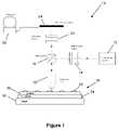
- FIG. 1shows a basic schematic of an embodiment 10 of a molecular interferometric imaging system viewing a sample 30 .
- the sample 30is placed on a stage 20 of the system 10 .
- the sample 30is not shown to scale in FIG. 1 to ease viewing and description.
- the sample 30includes a biolayer 32 that is located on a substrate 34 .
- a spacer 36is located between the biolayer 32 and the substrate 36 .
- FIG. 2shows a top-view of a portion of the sample 30 to be characterized by the system 10 .
- the sample 30includes the biolayer 32 that is to be analyzed by the system 10 and a land 33 that acts as a reference surface.
- the objective lens 18could be any one of numerous objective lens systems known in the art (e.g., coverslip corrected; coverslip uncorrected; long working distance).
- the objective lens 18is the imaging element in the system. It can be configured to work with or without coverslips.
- the objectiveIn the case of microfluidic systems, the objective should have a working distance that is compatible with the coverings over the microfluidic systems. In the case of conventional 96-well plate, the objective lens should have a long working distance. This can sometimes reduce the magnification, but a large numerical aperture (NA) system can retain high magnification even for long working distance.
- NAnumerical aperture
- Synchronization of the camera with an external triggercan be used to capture sequential images as some property is changed in the detection mode. For instance, synchronizing the camera with switching color filters, or synchronizing the camera with platform displacement or dither.
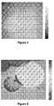
- the protein spot after execution of the platform shift and the calculation of the differential composite imageis shown in FIG. 5 .
- Most of the background variabilityis removed by the normalization procedure of Equation 4.
- the protein heights in the imageare several nanometers.
- FIG. 6shows a high resolution protein image of a uniformly printed 120 micron diameter protein spot.
- the protein heightis approximately 1-2 nanometers.
- the full range scaleis ⁇ 2 nm to 2 nm.
- Embodiments of the present inventioncan also operate under water.
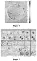
- the protein differential composite imageis shown in FIG. 11 under the two conditions of dry and wet.
- the proteinwas under a glass coverslip. Water was introduced between the slip and the disc surface.
- the proteinis still visible, with approximately a factor of 3 reduction in the signal intensity.
- dust and other background noisealso decreased by about a factor of 3 keeping the signal-to-noise ratio approximately constant.
- Detection sensitivityis set by the signal-to-noise ratio. Therefore, operation of the molecular interferometric imaging under water is feasible. This enables kinetic capture experiments in which binding could be tracked in real time. To detect real time binding, either the platform is dithered with synchronized image acquisition, or else successive images would be differenced and normalized to detect the binding.
- the in-line approachalso makes it possible to interrogate the proteins without going through the liquid.
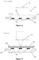
- FIG. 13One embodiment of this is shown in FIG. 13 .
- the imaging geometryis the same as that of FIG. 12 , but now the light passes through the upper glass slide 238 that carries the antibody spots and the bound analyte 234 .
- the in-line quadrature conditionis established by appropriate dielectric layers 232 .
- a top reflectioncan be the reference wave, and the reflection off the protein-carrying surface can be the signal wave.
- the addition of mass on the protein spot 234alters the phase of the reflected light that is detected through the in-line quadrature interfeormetry at the camera.
- This approachhas the advantage that the light does not pass through the liquid layer containing the analyte.
- the same operationcan be done for the adjacent land as shown in part (B) of FIG. 15 .
- an image with six multiple exposures of the landwhich is substantially clean and uniform, is captured at different positions in the field of view 250 .
- Different magnificationscan be used to capture more or less protein spots in the field of view.
Landscapes
- Physics & Mathematics (AREA)
- Health & Medical Sciences (AREA)
- Life Sciences & Earth Sciences (AREA)
- Chemical & Material Sciences (AREA)
- Analytical Chemistry (AREA)
- Biochemistry (AREA)
- General Health & Medical Sciences (AREA)
- General Physics & Mathematics (AREA)
- Immunology (AREA)
- Pathology (AREA)
- Spectroscopy & Molecular Physics (AREA)
- Investigating Or Analysing Materials By Optical Means (AREA)
- Investigating, Analyzing Materials By Fluorescence Or Luminescence (AREA)
- Investigating Or Analysing Materials By The Use Of Chemical Reactions (AREA)
Abstract
Description
ΔI=2√{square root over (IrefIsignal)}Δφ (1)
where the phase modulation caused by the molecules is:
where d is the effective thickness of the biolayer, nbis the refractive index of the biolayer, and nmis the refractive index of the surrounding medium. From a molecular point of view there is not a biolayer but rather a scattered distribution of molecules on the surface. Then the modulated phase is:
where rmis the molecular radius of gyration, and rsis the average molecular separation on the surface. The refractive index in this case is the refractive index associated with the individual molecules.
where IAis a pixel value from the
The refractive index measured for the protein layer in this way is approximately n=1.5.
Claims (34)
Priority Applications (2)
| Application Number | Priority Date | Filing Date | Title |
|---|---|---|---|
| US11/744,726US7522282B2 (en) | 2006-11-30 | 2007-05-04 | Molecular interferometric imaging process and apparatus |
| PCT/US2007/086059WO2008067528A2 (en) | 2006-11-30 | 2007-11-30 | Molecular interferometric imaging process and apparatus |
Applications Claiming Priority (2)
| Application Number | Priority Date | Filing Date | Title |
|---|---|---|---|
| US86796106P | 2006-11-30 | 2006-11-30 | |
| US11/744,726US7522282B2 (en) | 2006-11-30 | 2007-05-04 | Molecular interferometric imaging process and apparatus |
Publications (2)
| Publication Number | Publication Date |
|---|---|
| US20080129981A1 US20080129981A1 (en) | 2008-06-05 |
| US7522282B2true US7522282B2 (en) | 2009-04-21 |
Family
ID=39201865
Family Applications (1)
| Application Number | Title | Priority Date | Filing Date |
|---|---|---|---|
| US11/744,726Active2027-07-24US7522282B2 (en) | 2006-11-30 | 2007-05-04 | Molecular interferometric imaging process and apparatus |
Country Status (2)
| Country | Link |
|---|---|
| US (1) | US7522282B2 (en) |
| WO (1) | WO2008067528A2 (en) |
Cited By (13)
| Publication number | Priority date | Publication date | Assignee | Title |
|---|---|---|---|---|
| US20100176288A1 (en)* | 2007-06-01 | 2010-07-15 | Kratos Analytical Limited | Method and apparatus useful for imaging |
| US20110043814A1 (en)* | 2009-08-24 | 2011-02-24 | Raytheon Company | Ultra stable short pulse remote sensor |
| US7939363B1 (en) | 2010-10-27 | 2011-05-10 | General Electric Company | Systems and methods of intermixing cadmium sulfide layers and cadmium telluride layers for thin film photovoltaic devices |
| US7943415B1 (en) | 2010-10-27 | 2011-05-17 | Primestar Solar Inc. | Methods of sputtering cadmium sulfide layers for use in cadmium telluride based thin film photovoltaic devices |
| US20110157592A1 (en)* | 2009-12-31 | 2011-06-30 | Industrial Technology Research Institute | Surface plasmon resonance unit and inspection system using the same |
| US20120113424A1 (en)* | 2009-09-03 | 2012-05-10 | University Of Tokyo | Hydrogen Detecting Surface Plasmon Resonator, Surface Plasmon Resonance Optical Hydrogen Detector, and Method for Optically Detecting Hydrogen Using Surface Plasmon Resonance |
| US8188562B2 (en) | 2011-05-31 | 2012-05-29 | Primestar Solar, Inc. | Multi-layer N-type stack for cadmium telluride based thin film photovoltaic devices and methods of making |
| US8241930B2 (en) | 2011-05-31 | 2012-08-14 | Primestar Solar, Inc. | Methods of forming a window layer in a cadmium telluride based thin film photovoltaic device |
| US8247686B2 (en) | 2011-05-31 | 2012-08-21 | Primestar Solar, Inc. | Multi-layer N-type stack for cadmium telluride based thin film photovoltaic devices and methods of making |
| US8512950B2 (en) | 2010-07-21 | 2013-08-20 | Saint Louis University | Biolayer interferometry measurement of biological targets |
| US9054245B2 (en) | 2012-03-02 | 2015-06-09 | First Solar, Inc. | Doping an absorber layer of a photovoltaic device via diffusion from a window layer |
| US10824846B1 (en)* | 2017-10-06 | 2020-11-03 | Bo Xiao | Nanostructure pixel sensing method |
| US11644424B2 (en) | 2019-04-29 | 2023-05-09 | Waverly Industries, Llc | Interferometric method and apparatus for non-invasive assessment of oocyte maturity and competency |
Families Citing this family (13)
| Publication number | Priority date | Publication date | Assignee | Title |
|---|---|---|---|---|
| KR101416694B1 (en)* | 2008-06-11 | 2014-07-09 | 삼성전자 주식회사 | Analysing apparatus using rotatable microfluidic disk |
| ES2334318B2 (en)* | 2008-09-05 | 2011-11-28 | Universidad Politécnica de Madrid | OPTICAL DETECTION SYSTEM FOR BIO-TESTS OF HIGH SENSITIVITY SINMARCADO. |
| WO2010039147A1 (en)* | 2008-10-03 | 2010-04-08 | Purdue Research Foundation | Balanced-quadrature interferometric protein microarray |
| DE102009019711A1 (en)* | 2009-05-05 | 2010-11-18 | Biametrics Marken Und Rechte Gmbh | Method and device for determining reflection coefficients on thin-film filter arrangement |
| EP2327953B1 (en)* | 2009-11-20 | 2013-06-19 | Mitutoyo Corporation | Apparatus and method for determining a height map of a surface through both interferometric and non interferometric measurements. |
| US9733063B2 (en) | 2011-01-31 | 2017-08-15 | Biametrics Gmbh | Method and device for determining optical properties by simultaneous measurement of intensities at thin layers using light of several wavelengths |
| WO2015103459A1 (en)* | 2014-01-03 | 2015-07-09 | Arizona Board Of Regents On Behalf Of Arizona State University | Plasmonic imaging and detection of single dna molecules |
| US11047790B2 (en) | 2016-05-09 | 2021-06-29 | Trustees Of Boston University | Method and system for enhanced single particle reflectance imaging |
| EP3299799A1 (en)* | 2016-09-27 | 2018-03-28 | Berthold Technologies GmbH & Co. KG | Method and measuring system for measuring molecular interactions in a thin layer |
| US12099009B2 (en)* | 2018-10-04 | 2024-09-24 | Academia Sinica | Method and apparatus for surface plasmon resonance imaging |
| US20220026361A1 (en)* | 2018-12-18 | 2022-01-27 | Hewlett-Packard Development Company, L.P. | Ordered arrays of microdots |
| CN113251943A (en)* | 2020-02-12 | 2021-08-13 | 三营超精密光电(晋城)有限公司 | Measuring system and method based on light interference |
| CN113125437B (en)* | 2021-04-22 | 2023-07-18 | 华中科技大学 | Detection system and method based on optical interference scattering microscopy |
Citations (184)
| Publication number | Priority date | Publication date | Assignee | Title |
|---|---|---|---|---|
| US3796495A (en) | 1972-05-30 | 1974-03-12 | Zenith Radio Corp | Apparatus and methods for scanning phase profilometry |
| US4537861A (en) | 1983-02-03 | 1985-08-27 | Elings Virgil B | Apparatus and method for homogeneous immunoassay |
| US4741620A (en) | 1982-10-08 | 1988-05-03 | National Research Development Corporation | Irradiative probe system |
| US4876208A (en) | 1987-01-30 | 1989-10-24 | Yellowstone Diagnostics Corporation | Diffraction immunoassay apparatus and method |
| US4899195A (en) | 1988-01-29 | 1990-02-06 | Ushio Denki | Method of exposing a peripheral part of wafer |
| US4975237A (en) | 1987-03-12 | 1990-12-04 | The Secretary Of State For Defence In Her Britannic Majesty's Government Of The United Kingdom Of Great Britain And Northern Ireland | Dynamic light scattering apparatus |
| WO1991004489A1 (en) | 1989-09-20 | 1991-04-04 | The Royal Institution For The Advancement Of Learning (Mcgill University) | A homogeneous interferometric immunoassay system |
| WO1991004491A1 (en) | 1989-09-18 | 1991-04-04 | Biostar Medical Products, Inc. | Method and apparatus for detection of an analyte |
| USRE33581E (en) | 1984-06-25 | 1991-04-30 | Immunoassay using optical interference detection | |
| WO1991013353A1 (en) | 1990-02-22 | 1991-09-05 | The Royal Institution For The Advancement Of Learning (Mcgill University) | A solid-phase interferometric immunoassay system |
| US5122284A (en) | 1990-06-04 | 1992-06-16 | Abaxis, Inc. | Apparatus and method for optically analyzing biological fluids |
| WO1992014136A1 (en) | 1991-02-11 | 1992-08-20 | Biostar Medical Products, Inc. | Ellipsometric immunoassay system and method including a thin film detection device |
| US5155549A (en) | 1990-10-25 | 1992-10-13 | The Research Of State University Of New York | Method and apparatus for determining the physical properties of materials using dynamic light scattering techniques |
| WO1994003774A1 (en) | 1992-07-31 | 1994-02-17 | Biostar, Inc. | Devices and methods for detection of an analyte based upon light interference |
| US5413939A (en) | 1993-06-29 | 1995-05-09 | First Medical, Inc. | Solid-phase binding assay system for interferometrically measuring analytes bound to an active receptor |
| US5478750A (en) | 1993-03-31 | 1995-12-26 | Abaxis, Inc. | Methods for photometric analysis |
| US5478527A (en) | 1990-05-17 | 1995-12-26 | Adeza Biomedical Corporation | Highly reflective biogratings |
| US5494829A (en) | 1992-07-31 | 1996-02-27 | Biostar, Inc. | Devices and methods for detection of an analyte based upon light interference |
| US5497007A (en) | 1995-01-27 | 1996-03-05 | Applied Materials, Inc. | Method for automatically establishing a wafer coordinate system |
| US5545531A (en) | 1995-06-07 | 1996-08-13 | Affymax Technologies N.V. | Methods for making a device for concurrently processing multiple biological chip assays |
| US5581345A (en) | 1990-12-03 | 1996-12-03 | Nikon Corporation | Confocal laser scanning mode interference contrast microscope, and method of measuring minute step height and apparatus with said microscope |
| US5602377A (en) | 1995-03-01 | 1997-02-11 | Metanetics Corporation | Bar code dataform scanning and labeling apparatus and method |
| US5621532A (en) | 1994-12-08 | 1997-04-15 | Nikon Corporation | Laser scanning microscope utilizing detection of a far-field diffraction pattern with 2-dimensional detection |
| US5629044A (en) | 1995-01-31 | 1997-05-13 | Nobler Technologies, Inc. | Compact disc coating and handling system |
| US5653939A (en) | 1991-11-19 | 1997-08-05 | Massachusetts Institute Of Technology | Optical and electrical methods and apparatus for molecule detection |
| US5700046A (en) | 1995-09-13 | 1997-12-23 | Silicon Valley Group, Inc. | Wafer gripper |
| US5717778A (en) | 1993-02-26 | 1998-02-10 | Chu; Albert E. | Optical specimen analysis system and method |
| US5736257A (en) | 1995-04-25 | 1998-04-07 | Us Navy | Photoactivatable polymers for producing patterned biomolecular assemblies |
| US5781649A (en) | 1996-04-15 | 1998-07-14 | Phase Metrics, Inc. | Surface inspection of a disk by diffraction pattern sampling |
| US5786226A (en) | 1995-03-16 | 1998-07-28 | Boehringer Mannheim Gmbh | Quantitative transmission spectroscopy using sample carriers with nets |
| WO1998037238A3 (en) | 1997-02-21 | 1998-10-29 | Burstein Lab Inc | Gene sequencer and methods |
| US5837475A (en) | 1997-01-30 | 1998-11-17 | Hewlett-Packard Co. | Apparatus and method for scanning a chemical array |
| US5844871A (en) | 1996-02-13 | 1998-12-01 | Nec Corporation | Optical disk track counting apparatus and method for improved track access |
| US5843767A (en) | 1993-10-28 | 1998-12-01 | Houston Advanced Research Center | Microfabricated, flowthrough porous apparatus for discrete detection of binding reactions |
| US5875029A (en) | 1996-01-19 | 1999-02-23 | Phase Metrics, Inc. | Apparatus and method for surface inspection by specular interferometric and diffuse light detection |
| US5892577A (en) | 1994-09-21 | 1999-04-06 | The University Court Of The University Of Glasgow | Apparatus and method for carrying out analysis of samples |
| US5900935A (en) | 1997-12-22 | 1999-05-04 | Klein; Marvin B. | Homodyne interferometer and method of sensing material |
| US5922617A (en) | 1997-11-12 | 1999-07-13 | Functional Genetics, Inc. | Rapid screening assay methods and devices |
| US5935785A (en) | 1997-04-30 | 1999-08-10 | Motorola, Inc. | Binding assay methods |
| US5945344A (en) | 1995-06-07 | 1999-08-31 | Igen International, Inc. | Electrochemiluminescence method |
| US5955377A (en) | 1991-02-11 | 1999-09-21 | Biostar, Inc. | Methods and kits for the amplification of thin film based assays |
| US5968728A (en) | 1997-04-30 | 1999-10-19 | Motorola, Inc. | Molecular detection devices and methods of forming same |
| US5999262A (en) | 1996-04-19 | 1999-12-07 | Carl Zeiss Jena Gmbh | Process and apparatus for detecting structural changes of specimens |
| US6008892A (en) | 1997-05-23 | 1999-12-28 | Molecular Dynamics, Inc. | Optical substrate for enhanced detectability of fluorescence |
| WO2000000265A1 (en) | 1998-06-26 | 2000-01-06 | Biostar, Inc. | Filtration and extraction device and method of using the same |
| US6030581A (en) | 1997-02-28 | 2000-02-29 | Burstein Laboratories | Laboratory in a disk |
| US6048692A (en) | 1997-10-07 | 2000-04-11 | Motorola, Inc. | Sensors for electrically sensing binding events for supported molecular receptors |
| US6060237A (en) | 1985-02-26 | 2000-05-09 | Biostar, Inc. | Devices and methods for optical detection of nucleic acid hybridization |
| US6071748A (en) | 1997-07-16 | 2000-06-06 | Ljl Biosystems, Inc. | Light detection device |
| WO2000039584A1 (en) | 1998-12-29 | 2000-07-06 | Biostar, Inc. | Methods for providing liquid and solid components of a sample for use in assay methods |
| US6099803A (en) | 1994-07-07 | 2000-08-08 | Nanogen, Inc. | Advanced active electronic devices for molecular biological analysis and diagnostics |
| US6110748A (en) | 1997-04-30 | 2000-08-29 | Motorola, Inc. | Optical storage medium for binding assays |
| US6121048A (en) | 1994-10-18 | 2000-09-19 | Zaffaroni; Alejandro C. | Method of conducting a plurality of reactions |
| US6140044A (en) | 1994-06-08 | 2000-10-31 | Affymetrix, Inc. | Method and apparatus for packaging a probe array |
| US6143247A (en) | 1996-12-20 | 2000-11-07 | Gamera Bioscience Inc. | Affinity binding-based system for detecting particulates in a fluid |
| WO2001011310A1 (en) | 1999-08-06 | 2001-02-15 | Thermo Biostar, Inc. | Instruments for analyzing binding assays based on attenuation of light by thin films |
| US6221579B1 (en) | 1998-12-11 | 2001-04-24 | Kimberly-Clark Worldwide, Inc. | Patterned binding of functionalized microspheres for optical diffraction-based biosensors |
| US6238869B1 (en) | 1997-12-19 | 2001-05-29 | High Throughput Genomics, Inc. | High throughput assay system |
| US6248539B1 (en) | 1997-09-05 | 2001-06-19 | The Scripps Research Institute | Porous semiconductor-based optical interferometric sensor |
| WO2001044441A1 (en) | 1999-12-14 | 2001-06-21 | Thermo Biostar, Inc. | Stabilizing diluent for polypeptides and antigens |
| US6271924B1 (en) | 1998-12-29 | 2001-08-07 | Bryan Kok Ann Ngoi | Noncontact acoustic optic scanning laser vibrometer for determining the difference between an object and a reference surface |
| US6287850B1 (en) | 1995-06-07 | 2001-09-11 | Affymetrix, Inc. | Bioarray chip reaction apparatus and its manufacture |
| US6287783B1 (en) | 1999-03-18 | 2001-09-11 | Biostar, Inc. | Optical assay device and method |
| US6312961B1 (en) | 1998-05-22 | 2001-11-06 | Csem Centre Suisse D'electronique Et De Microtechnique Sa | Optical sensor using an immunological reaction and a fluorescent marker |
| US6312901B2 (en) | 1996-07-08 | 2001-11-06 | Burstein Technologies, Inc. | Spatially addressable, cleavable reflective signal elements, assay device and method |
| US6319469B1 (en) | 1995-12-18 | 2001-11-20 | Silicon Valley Bank | Devices and methods for using centripetal acceleration to drive fluid movement in a microfluidics system |
| US6320665B1 (en) | 1998-12-29 | 2001-11-20 | Bryan Kok Ann Ngoi | Acousto optic scanning laser vibrometer for determining the dynamic properties of an object |
| US6327031B1 (en) | 1998-09-18 | 2001-12-04 | Burstein Technologies, Inc. | Apparatus and semi-reflective optical system for carrying out analysis of samples |
| US20020001546A1 (en) | 1998-01-12 | 2002-01-03 | Massachusetts Institute Of Technology | Methods for screening substances in a microwell array |
| US20020008871A1 (en) | 1998-12-14 | 2002-01-24 | Annemarie Poustka | Method and device for detecting optical properties, especially luminescence reactions and refraction behavior of molecules which are directly or indirectly bound on a support |
| US6342349B1 (en) | 1996-07-08 | 2002-01-29 | Burstein Technologies, Inc. | Optical disk-based assay devices and methods |
| US6342395B1 (en) | 1998-04-22 | 2002-01-29 | The Regents Of The University Of California | Compact assay system with digital information |
| US6345115B1 (en) | 1997-08-07 | 2002-02-05 | Imaging Research, Inc. | Digital imaging system for assays in well plates, gels and blots |
| US6350413B1 (en) | 1995-02-23 | 2002-02-26 | University Of Utah Research Foundation | Integrated optic waveguide immunosensor |
| EP1189062A1 (en) | 2000-09-18 | 2002-03-20 | James J. Dr. La Clair | Method and device for identifying molecular species |
| US6368795B1 (en) | 1998-02-02 | 2002-04-09 | Signature Bioscience, Inc. | Bio-assay device and test system for detecting molecular binding events |
| US20020045276A1 (en) | 1996-04-25 | 2002-04-18 | Juan Yguerabide | Analyte assay using particulate labels |
| US6376258B2 (en) | 1998-02-02 | 2002-04-23 | Signature Bioscience, Inc. | Resonant bio-assay device and test system for detecting molecular binding events |
| US6381025B1 (en) | 1999-08-19 | 2002-04-30 | Texas Tech University | Interferometric detection system and method |
| US20020051973A1 (en) | 1999-09-17 | 2002-05-02 | Glenda C. Delenstarr | Techniques for assessing nonspecific binding of nucleic acids to surfaces |
| US6387331B1 (en) | 1998-01-12 | 2002-05-14 | Massachusetts Institute Of Technology | Method and apparatus for performing microassays |
| US20020058242A1 (en) | 1996-09-20 | 2002-05-16 | James Paul Demers | Spatially addressable combinatorial chemical arrays in cd-rom format |
| US6395558B1 (en) | 1996-08-29 | 2002-05-28 | Zeptosens Ag | Optical chemical/biochemical sensor |
| US6395562B1 (en) | 1998-04-22 | 2002-05-28 | The Regents Of The University Of California | Diagnostic microarray apparatus |
| US6403957B1 (en) | 1989-06-07 | 2002-06-11 | Affymetrix, Inc. | Nucleic acid reading and analysis system |
| US6416642B1 (en) | 1999-01-21 | 2002-07-09 | Caliper Technologies Corp. | Method and apparatus for continuous liquid flow in microscale channels using pressure injection, wicking, and electrokinetic injection |
| US20020097658A1 (en) | 2000-12-08 | 2002-07-25 | Worthington Mark O. | Multiple data layer optical discs for detecting analytes |
| US20020106661A1 (en) | 1996-07-08 | 2002-08-08 | Burstein Laboratories, Inc. | Optical disk-based assay devices and methods |
| US20020127565A1 (en) | 2000-10-30 | 2002-09-12 | Sru Biosystems, Llc | Label-free high-throughput optical technique for detecting biomolecular interactions |
| US20020151043A1 (en) | 2001-04-11 | 2002-10-17 | Gordon John Francis | Multi-parameter assays including analysis discs and methods relating thereto |
| US6469787B1 (en) | 2001-04-03 | 2002-10-22 | Ohio Aerospace Institute | Dynamic light scattering homodyne probe |
| US6483588B1 (en) | 1998-06-26 | 2002-11-19 | Carl Zeiss Jena Gmbh | Arrangement for detecting biomolecular reactions and interactions |
| US6496309B1 (en) | 1999-06-18 | 2002-12-17 | Genomic Solutions, Inc. | Automated, CCD-based DNA micro-array imaging system |
| US6504618B2 (en) | 2001-03-21 | 2003-01-07 | Rudolph Technologies, Inc. | Method and apparatus for decreasing thermal loading and roughness sensitivity in a photoacoustic film thickness measurement system |
| US20030026735A1 (en) | 2001-06-22 | 2003-02-06 | Nolte David D. | Bio-optical compact disk system |
| US6518056B2 (en) | 1999-04-27 | 2003-02-11 | Agilent Technologies Inc. | Apparatus, systems and method for assaying biological materials using an annular format |
| US20030035352A1 (en) | 2001-07-12 | 2003-02-20 | Worthington Mark Oscar | Optical disc system and related detecting methods for analysis of microscopic structures |
| US20030054376A1 (en) | 1997-07-07 | 2003-03-20 | Mullis Kary Banks | Dual bead assays using cleavable spacers and/or ligation to improve specificity and sensitivity including related methods and apparatus |
| US20030112446A1 (en) | 2001-10-26 | 2003-06-19 | Benjamin Miller | Method for biomolecular sensing and system thereof |
| US6584217B1 (en) | 1995-06-05 | 2003-06-24 | E Y Laboratories, Inc. | Reflectometry system with compensation for specimen holder topography and with lock-rejection of system noise |
| US6591196B1 (en) | 2000-06-06 | 2003-07-08 | Agilent Technologies Inc. | Method and system for extracting data from surface array deposited features |
| US20030133640A1 (en) | 2000-08-09 | 2003-07-17 | Kurt Tiefenthaler | Waveguide grid array and optical measurement arrangement |
| US20030134330A1 (en) | 1999-04-15 | 2003-07-17 | Ilya Ravkin | Chemical-library composition and method |
| US6596483B1 (en) | 1999-11-12 | 2003-07-22 | Motorola, Inc. | System and method for detecting molecules using an active pixel sensor |
| US6602702B1 (en) | 1999-07-16 | 2003-08-05 | The University Of Texas System | Detection system based on an analyte reactive particle |
| US6623696B1 (en) | 1999-10-29 | 2003-09-23 | Lg. Electronics, Inc. | Biochip, apparatus for detecting biomaterials using the same, and method therefor |
| US6624896B1 (en) | 1999-10-18 | 2003-09-23 | Wavefront Sciences, Inc. | System and method for metrology of surface flatness and surface nanotopology of materials |
| US6649403B1 (en) | 2000-01-31 | 2003-11-18 | Board Of Regents, The University Of Texas Systems | Method of preparing a sensor array |
| US6653152B2 (en) | 1997-11-19 | 2003-11-25 | Imation Corp. | Sensor disk having radial grooves and optical assaying method using same |
| US6656428B1 (en) | 1999-08-06 | 2003-12-02 | Thermo Biostar, Inc. | Automated point of care detection system including complete sample processing capabilities |
| US6687008B1 (en) | 2000-10-19 | 2004-02-03 | Kla-Tencor Corporation | Waveguide based parallel multi-phaseshift interferometry for high speed metrology, optical inspection, and non-contact sensing |
| US6709869B2 (en) | 1995-12-18 | 2004-03-23 | Tecan Trading Ag | Devices and methods for using centripetal acceleration to drive fluid movement in a microfluidics system |
| US20040078337A1 (en) | 2001-08-06 | 2004-04-22 | King Shawn L. | Electronic document management system and method |
| US6734000B2 (en) | 2000-10-12 | 2004-05-11 | Regents Of The University Of California | Nanoporous silicon support containing macropores for use as a bioreactor |
| US6737238B2 (en) | 1999-04-16 | 2004-05-18 | Canon Kabushiki Kaisha | Substrate measuring method and device |
| EP1424549A1 (en) | 2001-08-07 | 2004-06-02 | Mitsubishi Chemical Corporation | SURFACE PLASMON RESONANCE SENSOR CHIP, AND SAMPLE ANALYSIS METHOD AND ANALYSIS APPARATUS USING THE SAME |
| US6766817B2 (en) | 2001-07-25 | 2004-07-27 | Tubarc Technologies, Llc | Fluid conduction utilizing a reversible unsaturated siphon with tubarc porosity action |
| US20040150829A1 (en) | 2001-04-17 | 2004-08-05 | Peter Koch | Interferometric arrangement for determining the transit time of light in a sample |
| US20040166593A1 (en) | 2001-06-22 | 2004-08-26 | Nolte David D. | Adaptive interferometric multi-analyte high-speed biosensor |
| US6787110B2 (en) | 1997-09-10 | 2004-09-07 | Artificial Sensing Instruments Asi Ag | Optical sensor and optical process for the characterization of a chemical and/or bio-chemical substance |
| US6791677B2 (en) | 2001-08-28 | 2004-09-14 | Tosoh Corporation | Information measuring apparatus using a fine channel device |
| US6806963B1 (en) | 1999-11-24 | 2004-10-19 | Haag-Streit Ag | Method and device for measuring the optical properties of at least two regions located at a distance from one another in a transparent and/or diffuse object |
| US20040223881A1 (en) | 2003-05-08 | 2004-11-11 | Sru Biosystems | Detection of biochemical interactions on a biosensor using tunable filters and tunable lasers |
| US6819432B2 (en) | 2001-03-14 | 2004-11-16 | Hrl Laboratories, Llc | Coherent detecting receiver using a time delay interferometer and adaptive beam combiner |
| US20040229254A1 (en) | 2003-03-11 | 2004-11-18 | The Regents Of The University Of California | Method and device for identifying molecular species |
| US20040258927A1 (en) | 2003-06-23 | 2004-12-23 | Conzone Samuel D. | Non-destructive quality control method for microarray substrate coatings via labeled doping |
| US6836338B2 (en) | 1997-07-03 | 2004-12-28 | Therma-Wave, Inc. | Apparatus for evaluating metalized layers on semiconductors |
| US20050003459A1 (en) | 2002-01-30 | 2005-01-06 | Krutzik Siegfried Richard | Multi-purpose optical analysis disc for conducting assays and related methods for attaching capture agents |
| US20050002827A1 (en) | 2002-01-29 | 2005-01-06 | Mcintyre Kevin Robert | Optical discs including equi-radial and/or spiral analysis zones and related disc drive systems and methods |
| US6844965B1 (en) | 1999-11-29 | 2005-01-18 | Leica Microsystems Heidelberg Gmbh | Apparatus for optical scanning of multiple specimens |
| US6847452B2 (en) | 2001-08-02 | 2005-01-25 | Zygo Corporation | Passive zero shear interferometers |
| US20050019901A1 (en) | 2002-01-31 | 2005-01-27 | Evgenia Matveeva | Methods for synthesis of bio-active nanoparticles and nanocapsules for use in optical bio-disc assays and disc assembly including same |
| US20050042628A1 (en) | 1995-06-07 | 2005-02-24 | Affymetrix, Inc. | Methods for concurrently processing multiple biological chip assays |
| US6878555B2 (en) | 2001-10-21 | 2005-04-12 | Gyros Ab | Method and instrumentation for micro dispensation of droplets |
| US20050084422A1 (en) | 2003-06-19 | 2005-04-21 | Horacio Kido | Fluidic circuits for sample preparation including bio-discs and methods relating thereto |
| US20050106746A1 (en) | 1999-11-26 | 2005-05-19 | Associates Of Cape Cod, Inc. | Reader for conducting assays |
| US20050131745A1 (en) | 2003-12-12 | 2005-06-16 | Wiredtime.Com Inc. | Barcode based time tracking method and system |
| US6917421B1 (en) | 2001-10-12 | 2005-07-12 | Kla-Tencor Technologies Corp. | Systems and methods for multi-dimensional inspection and/or metrology of a specimen |
| US6917432B2 (en) | 2001-10-19 | 2005-07-12 | Zygo Corporation | Interferometers for measuring changes in optical beam direction |
| US6937323B2 (en) | 2000-11-08 | 2005-08-30 | Burstein Technologies, Inc. | Interactive system for analyzing biological samples and processing related information and the use thereof |
| US20050214950A1 (en) | 2004-03-23 | 2005-09-29 | Roeder Jeffrey F | Optical disk based gas-sensing and storage device |
| US20050226769A1 (en) | 2004-04-08 | 2005-10-13 | Matsushita Elec. Ind. Co. Ltd. | Analytical apparatus and analytical disk for use therein |
| US6955878B2 (en) | 1998-03-05 | 2005-10-18 | Hitachi, Ltd. | Apparatus for analyzing samples using linear probe array |
| US20050248754A1 (en) | 2004-05-05 | 2005-11-10 | Chun-Sheng Wang | Wafer aligner with WEE (water edge exposure) function |
| US20050254062A1 (en) | 2003-11-06 | 2005-11-17 | Fortebio, Inc. | Fiber-optic assay apparatus based on phase-shift interferometry |
| US20050259260A1 (en) | 2002-06-19 | 2005-11-24 | Matsushita Electric Industrial Co., Ltd. | Analyzing apparatus and analyzed disc used in the same |
| US6980299B1 (en) | 2001-10-16 | 2005-12-27 | General Hospital Corporation | Systems and methods for imaging a sample |
| US6980677B2 (en) | 2002-05-24 | 2005-12-27 | Niles Scientific, Inc. | Method, system, and computer code for finding spots defined in biological microarrays |
| US6987569B2 (en) | 2001-08-23 | 2006-01-17 | Zygo Corporation | Dynamic interferometer controlling direction of input beam |
| US6990221B2 (en) | 1998-02-07 | 2006-01-24 | Biodiscovery, Inc. | Automated DNA array image segmentation and analysis |
| US6995845B2 (en) | 2000-12-08 | 2006-02-07 | Burstein Technologies, Inc. | Methods for detecting analytes using optical discs and optical disc readers |
| US7006927B2 (en) | 2000-06-06 | 2006-02-28 | Agilent Technologies, Inc. | Method and system for extracting data from surface array deposited features |
| US7008794B2 (en) | 2000-03-22 | 2006-03-07 | Axela Biosensors Inc. | Method and apparatus for assay for multiple analytes |
| US7012249B2 (en) | 2000-12-15 | 2006-03-14 | The Rockefeller University | High capacity and scanning speed system for sample handling and analysis |
| US7014815B1 (en) | 1998-10-30 | 2006-03-21 | Burstein Technologies, Inc. | Trackable optical discs with concurrently readable nonoperational features |
| US7026131B2 (en) | 2000-11-17 | 2006-04-11 | Nagaoka & Co., Ltd. | Methods and apparatus for blood typing with optical bio-discs |
| US7027163B2 (en) | 2003-01-24 | 2006-04-11 | General Dynamics Advanced Information Systems, Inc. | Grating sensor |
| US20060078935A1 (en) | 2001-05-18 | 2006-04-13 | Werner Martin E | Surface assembly for immobilizing DNA capture probes in genetic assays using enzymatic reactions to generate signal in optical bio-discs and methods relating thereto |
| WO2006042746A1 (en) | 2004-10-19 | 2006-04-27 | Universität Tübingen | Method for examining physical, chemical and biochemical interactions |
| US7042570B2 (en) | 2002-01-25 | 2006-05-09 | The Regents Of The University Of California | Porous thin film time-varying reflectivity analysis of samples |
| US7061594B2 (en) | 2000-11-09 | 2006-06-13 | Burstein Technologies, Inc. | Disc drive system and methods for use with bio-discs |
| US7070987B2 (en) | 2000-10-30 | 2006-07-04 | Sru Biosystems, Inc. | Guided mode resonant filter biosensor using a linear grating surface structure |
| US7077996B2 (en) | 2003-07-15 | 2006-07-18 | Randall Brandon L | Methods and apparatus for blood separation and analysis using membranes on an optical bio-disc |
| US7087203B2 (en) | 2000-11-17 | 2006-08-08 | Nagaoka & Co., Ltd. | Methods and apparatus for blood typing with optical bio-disc |
| US7088650B1 (en) | 1999-08-23 | 2006-08-08 | Worthington Mark O | Methods and apparatus for optical disc data acquisition using physical synchronization markers |
| US7091034B2 (en) | 2000-12-15 | 2006-08-15 | Burstein Technologies, Inc. | Detection system for disk-based laboratory and improved optical bio-disc including same |
| US7091049B2 (en) | 2002-06-26 | 2006-08-15 | Kimberly-Clark Worldwide, Inc. | Enhanced diffraction-based biosensor devices |
| US7098041B2 (en) | 2001-12-11 | 2006-08-29 | Kimberly-Clark Worldwide, Inc. | Methods to view and analyze the results from diffraction-based diagnostics |
| US7102752B2 (en) | 2001-12-11 | 2006-09-05 | Kimberly-Clark Worldwide, Inc. | Systems to view and analyze the results from diffraction-based diagnostics |
| US7106513B2 (en) | 2002-08-20 | 2006-09-12 | Illumina, Inc. | Diffraction grating-based encoded particle |
| US20060204399A1 (en) | 2002-12-30 | 2006-09-14 | Freeman Dominique M | Method and apparatus using optical techniques to measure analyte levels |
| US20060210449A1 (en) | 2000-11-16 | 2006-09-21 | Zoval Jim V | Optical biodiscs with reflective layers |
| US20060223172A1 (en) | 2005-04-01 | 2006-10-05 | 3M Innovative Properties Company | Multiplex fluorescence detection device having fiber bundle coupling multiple optical modules to a common detector |
| US7118855B2 (en) | 2002-05-03 | 2006-10-10 | Kimberly-Clark Worldwide, Inc. | Diffraction-based diagnostic devices |
| US20060256350A1 (en) | 2005-02-01 | 2006-11-16 | David Nolte | Laser scanning interferometric surface metrology |
| US7141416B2 (en) | 2001-07-12 | 2006-11-28 | Burstein Technologies, Inc. | Multi-purpose optical analysis optical bio-disc for conducting assays and various reporting agents for use therewith |
| US7141378B2 (en) | 2004-07-02 | 2006-11-28 | Blueshift Biotechnologies, Inc. | Exploring fluorophore microenvironments |
| US20060269450A1 (en) | 2005-05-27 | 2006-11-30 | Kim Yong M | Sensing apparatus having rotating optical assembly |
| US7145645B2 (en) | 1999-11-04 | 2006-12-05 | Regents Of The University Of Minnesota | Imaging of biological samples using electronic light detector |
| US20070003925A1 (en) | 2005-02-01 | 2007-01-04 | Nolte David D | Multiplexed biological analyzer planar array apparatus and methods |
| US20070003979A1 (en) | 1998-10-30 | 2007-01-04 | Worthington Mark O | Trackable optical discs with concurrently readable analyte material |
| US20070023643A1 (en) | 2005-02-01 | 2007-02-01 | Nolte David D | Differentially encoded biological analyzer planar array apparatus and methods |
| US7200088B2 (en) | 2001-01-11 | 2007-04-03 | Burstein Technologies, Inc. | System and method of detecting investigational features related to a sample |
| US7345770B2 (en)* | 2004-11-08 | 2008-03-18 | Kabushiki Kaisha Topcon | Optical image measuring apparatus and optical image measuring method for forming a velocity distribution image expressing a moving velocity distribution of the moving matter |
Family Cites Families (1)
| Publication number | Priority date | Publication date | Assignee | Title |
|---|---|---|---|---|
| US6540618B1 (en)* | 2000-09-26 | 2003-04-01 | The Torrington Company | Steering column slider assembly |
- 2007
- 2007-05-04USUS11/744,726patent/US7522282B2/enactiveActive
- 2007-11-30WOPCT/US2007/086059patent/WO2008067528A2/enactiveApplication Filing
Patent Citations (243)
| Publication number | Priority date | Publication date | Assignee | Title |
|---|---|---|---|---|
| US3796495A (en) | 1972-05-30 | 1974-03-12 | Zenith Radio Corp | Apparatus and methods for scanning phase profilometry |
| US4741620A (en) | 1982-10-08 | 1988-05-03 | National Research Development Corporation | Irradiative probe system |
| US4537861A (en) | 1983-02-03 | 1985-08-27 | Elings Virgil B | Apparatus and method for homogeneous immunoassay |
| USRE33581E (en) | 1984-06-25 | 1991-04-30 | Immunoassay using optical interference detection | |
| US20020192664A1 (en) | 1985-02-26 | 2002-12-19 | Thermo Biostar, Inc. | Devices and methods for optical detection of nucleic acid hybridization |
| US6783938B2 (en) | 1985-02-26 | 2004-08-31 | Biostar, Inc. | Devices for optical detection of nucleic acid hybridization |
| US6060237A (en) | 1985-02-26 | 2000-05-09 | Biostar, Inc. | Devices and methods for optical detection of nucleic acid hybridization |
| US6355429B1 (en) | 1985-02-26 | 2002-03-12 | Thermo Biostar Inc. | Devices and methods for optical detection of nucleic acid hybridization |
| US4876208A (en) | 1987-01-30 | 1989-10-24 | Yellowstone Diagnostics Corporation | Diffraction immunoassay apparatus and method |
| US4975237A (en) | 1987-03-12 | 1990-12-04 | The Secretary Of State For Defence In Her Britannic Majesty's Government Of The United Kingdom Of Great Britain And Northern Ireland | Dynamic light scattering apparatus |
| US4899195A (en) | 1988-01-29 | 1990-02-06 | Ushio Denki | Method of exposing a peripheral part of wafer |
| US6403957B1 (en) | 1989-06-07 | 2002-06-11 | Affymetrix, Inc. | Nucleic acid reading and analysis system |
| WO1991004491A1 (en) | 1989-09-18 | 1991-04-04 | Biostar Medical Products, Inc. | Method and apparatus for detection of an analyte |
| WO1991004489A1 (en) | 1989-09-20 | 1991-04-04 | The Royal Institution For The Advancement Of Learning (Mcgill University) | A homogeneous interferometric immunoassay system |
| WO1991013353A1 (en) | 1990-02-22 | 1991-09-05 | The Royal Institution For The Advancement Of Learning (Mcgill University) | A solid-phase interferometric immunoassay system |
| US5478527A (en) | 1990-05-17 | 1995-12-26 | Adeza Biomedical Corporation | Highly reflective biogratings |
| US5122284A (en) | 1990-06-04 | 1992-06-16 | Abaxis, Inc. | Apparatus and method for optically analyzing biological fluids |
| US5155549A (en) | 1990-10-25 | 1992-10-13 | The Research Of State University Of New York | Method and apparatus for determining the physical properties of materials using dynamic light scattering techniques |
| US5581345A (en) | 1990-12-03 | 1996-12-03 | Nikon Corporation | Confocal laser scanning mode interference contrast microscope, and method of measuring minute step height and apparatus with said microscope |
| US5955377A (en) | 1991-02-11 | 1999-09-21 | Biostar, Inc. | Methods and kits for the amplification of thin film based assays |
| WO1992014136A1 (en) | 1991-02-11 | 1992-08-20 | Biostar Medical Products, Inc. | Ellipsometric immunoassay system and method including a thin film detection device |
| US5653939A (en) | 1991-11-19 | 1997-08-05 | Massachusetts Institute Of Technology | Optical and electrical methods and apparatus for molecule detection |
| WO1994003774A1 (en) | 1992-07-31 | 1994-02-17 | Biostar, Inc. | Devices and methods for detection of an analyte based upon light interference |
| US5494829A (en) | 1992-07-31 | 1996-02-27 | Biostar, Inc. | Devices and methods for detection of an analyte based upon light interference |
| US5631171A (en) | 1992-07-31 | 1997-05-20 | Biostar, Inc. | Method and instrument for detection of change of thickness or refractive index for a thin film substrate |
| US6249593B1 (en) | 1993-02-26 | 2001-06-19 | Ey Laboratories, Inc. | Optical specimen analysis system and method |
| US5717778A (en) | 1993-02-26 | 1998-02-10 | Chu; Albert E. | Optical specimen analysis system and method |
| US7031508B2 (en) | 1993-02-26 | 2006-04-18 | E Y Laboratories, Inc. | Reflectometry system with compensation for specimen holder topography and with lock-rejection of system noise |
| US5478750A (en) | 1993-03-31 | 1995-12-26 | Abaxis, Inc. | Methods for photometric analysis |
| US5413939A (en) | 1993-06-29 | 1995-05-09 | First Medical, Inc. | Solid-phase binding assay system for interferometrically measuring analytes bound to an active receptor |
| US5843767A (en) | 1993-10-28 | 1998-12-01 | Houston Advanced Research Center | Microfabricated, flowthrough porous apparatus for discrete detection of binding reactions |
| US20050084895A1 (en) | 1994-06-08 | 2005-04-21 | Affymetrix, Inc. | Bioarray chip reaction apparatus and its manufacture |
| US6140044A (en) | 1994-06-08 | 2000-10-31 | Affymetrix, Inc. | Method and apparatus for packaging a probe array |
| US6399365B2 (en) | 1994-06-08 | 2002-06-04 | Affymetrix, Inc. | Bioarray chip reaction apparatus and its manufacture |
| US6551817B2 (en) | 1994-06-08 | 2003-04-22 | Affymetrix, Inc. | Method and apparatus for hybridization |
| US20050158819A1 (en) | 1994-06-08 | 2005-07-21 | Affymetrix, Inc. | Bioarray chip reaction apparatus and its manufacture |
| US20060234267A1 (en) | 1994-06-08 | 2006-10-19 | Affymetrix, Inc | Bioarray chip reaction apparatus and its manufacture |
| US20060040380A1 (en) | 1994-06-08 | 2006-02-23 | Affymetrix, Inc. | Bioarray chip reaction apparatus and its manufacture |
| US6733977B2 (en) | 1994-06-08 | 2004-05-11 | Affymetrix, Inc. | Hybridization device and method |
| US20040166525A1 (en) | 1994-06-08 | 2004-08-26 | Affymetrix, Inc. | Bioarray chip reaction apparatus and its manufacture |
| US20040106130A1 (en) | 1994-06-08 | 2004-06-03 | Affymetrix, Inc. | Bioarray chip reaction apparatus and its manufacture |
| US20050191630A1 (en) | 1994-06-08 | 2005-09-01 | Affymetrix, Inc., A Delaware Corporation. | Bioarray chip reaction apparatus and its manufacture |
| US6099803A (en) | 1994-07-07 | 2000-08-08 | Nanogen, Inc. | Advanced active electronic devices for molecular biological analysis and diagnostics |
| US6256088B1 (en) | 1994-09-21 | 2001-07-03 | University Court Of The University Of Glasgow, The | Apparatus and method for carrying out analysis of samples |
| US7110094B2 (en) | 1994-09-21 | 2006-09-19 | Burstein Technologies, Inc. | Apparatus and method for carrying out analysis of samples using radiation detector output ratios |
| US6339473B1 (en) | 1994-09-21 | 2002-01-15 | The University Court Of The University Of Glasgow | Apparatus and method for carrying out analysis of samples |
| US6476907B1 (en) | 1994-09-21 | 2002-11-05 | The University Court Of The University Of Glasgow | Apparatus and method for carrying out histological analysis of specimens |
| US6803999B1 (en) | 1994-09-21 | 2004-10-12 | John Francis Gordon | Analytical disc with optically trackable encoded information and related optical inspection system |
| US20020135754A1 (en) | 1994-09-21 | 2002-09-26 | The University Court Of The University Of Glasgow | Apparatus and method for carrying out analysis of samples using radiation detector split beam radiation inspection |
| US20020085202A1 (en) | 1994-09-21 | 2002-07-04 | University Court Of The University Of Glasgow | Apparatus and method for carrying out analysis of samples using radiation detector output ratios |
| US5892577A (en) | 1994-09-21 | 1999-04-06 | The University Court Of The University Of Glasgow | Apparatus and method for carrying out analysis of samples |
| US6992769B2 (en) | 1994-09-21 | 2006-01-31 | Nagaoka & Co., Ltd. | Apparatus and method for carrying out analysis of samples using semi-reflective beam radiation inspection |
| US20050176058A1 (en) | 1994-10-18 | 2005-08-11 | Affymetrix, Inc. | Guided deposition in spatial arrays |
| US6121048A (en) | 1994-10-18 | 2000-09-19 | Zaffaroni; Alejandro C. | Method of conducting a plurality of reactions |
| US5621532A (en) | 1994-12-08 | 1997-04-15 | Nikon Corporation | Laser scanning microscope utilizing detection of a far-field diffraction pattern with 2-dimensional detection |
| US5497007A (en) | 1995-01-27 | 1996-03-05 | Applied Materials, Inc. | Method for automatically establishing a wafer coordinate system |
| US5629044A (en) | 1995-01-31 | 1997-05-13 | Nobler Technologies, Inc. | Compact disc coating and handling system |
| US6350413B1 (en) | 1995-02-23 | 2002-02-26 | University Of Utah Research Foundation | Integrated optic waveguide immunosensor |
| US5602377A (en) | 1995-03-01 | 1997-02-11 | Metanetics Corporation | Bar code dataform scanning and labeling apparatus and method |
| US5786226A (en) | 1995-03-16 | 1998-07-28 | Boehringer Mannheim Gmbh | Quantitative transmission spectroscopy using sample carriers with nets |
| US5736257A (en) | 1995-04-25 | 1998-04-07 | Us Navy | Photoactivatable polymers for producing patterned biomolecular assemblies |
| US6584217B1 (en) | 1995-06-05 | 2003-06-24 | E Y Laboratories, Inc. | Reflectometry system with compensation for specimen holder topography and with lock-rejection of system noise |
| US20050123907A1 (en) | 1995-06-07 | 2005-06-09 | Affymetrix, Inc. | Methods for making a device for concurrently processing multiple biological chip assays |
| US5545531A (en) | 1995-06-07 | 1996-08-13 | Affymax Technologies N.V. | Methods for making a device for concurrently processing multiple biological chip assays |
| US5874219A (en) | 1995-06-07 | 1999-02-23 | Affymetrix, Inc. | Methods for concurrently processing multiple biological chip assays |
| US6287850B1 (en) | 1995-06-07 | 2001-09-11 | Affymetrix, Inc. | Bioarray chip reaction apparatus and its manufacture |
| US5945344A (en) | 1995-06-07 | 1999-08-31 | Igen International, Inc. | Electrochemiluminescence method |
| US20050042628A1 (en) | 1995-06-07 | 2005-02-24 | Affymetrix, Inc. | Methods for concurrently processing multiple biological chip assays |
| US6319468B1 (en) | 1995-06-27 | 2001-11-20 | Tecan Trading Ag | Affinity binding-based system for detecting particulates in a fluid |
| US5700046A (en) | 1995-09-13 | 1997-12-23 | Silicon Valley Group, Inc. | Wafer gripper |
| US20010055812A1 (en) | 1995-12-05 | 2001-12-27 | Alec Mian | Devices and method for using centripetal acceleration to drive fluid movement in a microfluidics system with on-board informatics |
| US6709869B2 (en) | 1995-12-18 | 2004-03-23 | Tecan Trading Ag | Devices and methods for using centripetal acceleration to drive fluid movement in a microfluidics system |
| US6319469B1 (en) | 1995-12-18 | 2001-11-20 | Silicon Valley Bank | Devices and methods for using centripetal acceleration to drive fluid movement in a microfluidics system |
| US5875029A (en) | 1996-01-19 | 1999-02-23 | Phase Metrics, Inc. | Apparatus and method for surface inspection by specular interferometric and diffuse light detection |
| US5844871A (en) | 1996-02-13 | 1998-12-01 | Nec Corporation | Optical disk track counting apparatus and method for improved track access |
| US5781649A (en) | 1996-04-15 | 1998-07-14 | Phase Metrics, Inc. | Surface inspection of a disk by diffraction pattern sampling |
| US5999262A (en) | 1996-04-19 | 1999-12-07 | Carl Zeiss Jena Gmbh | Process and apparatus for detecting structural changes of specimens |
| US20020045276A1 (en) | 1996-04-25 | 2002-04-18 | Juan Yguerabide | Analyte assay using particulate labels |
| US6312901B2 (en) | 1996-07-08 | 2001-11-06 | Burstein Technologies, Inc. | Spatially addressable, cleavable reflective signal elements, assay device and method |
| US6342349B1 (en) | 1996-07-08 | 2002-01-29 | Burstein Technologies, Inc. | Optical disk-based assay devices and methods |
| US20020106661A1 (en) | 1996-07-08 | 2002-08-08 | Burstein Laboratories, Inc. | Optical disk-based assay devices and methods |
| US6395558B1 (en) | 1996-08-29 | 2002-05-28 | Zeptosens Ag | Optical chemical/biochemical sensor |
| US7094609B2 (en) | 1996-09-20 | 2006-08-22 | Burstein Technologies, Inc. | Spatially addressable combinatorial chemical arrays in encoded optical disk format |
| US20060257939A1 (en) | 1996-09-20 | 2006-11-16 | Burstein Technologies, Inc. | Spatially addressable combinatorial chemical array in cd-rom format |
| US20020058242A1 (en) | 1996-09-20 | 2002-05-16 | James Paul Demers | Spatially addressable combinatorial chemical arrays in cd-rom format |
| US6143247A (en) | 1996-12-20 | 2000-11-07 | Gamera Bioscience Inc. | Affinity binding-based system for detecting particulates in a fluid |
| US5837475A (en) | 1997-01-30 | 1998-11-17 | Hewlett-Packard Co. | Apparatus and method for scanning a chemical array |
| US6566069B2 (en) | 1997-02-21 | 2003-05-20 | Burstein Technologies, Inc. | Gene sequencer and method for determining the nucleotide sequence of a chromosome |
| WO1998037238A3 (en) | 1997-02-21 | 1998-10-29 | Burstein Lab Inc | Gene sequencer and methods |
| US6030581A (en) | 1997-02-28 | 2000-02-29 | Burstein Laboratories | Laboratory in a disk |
| US5968728A (en) | 1997-04-30 | 1999-10-19 | Motorola, Inc. | Molecular detection devices and methods of forming same |
| US5935785A (en) | 1997-04-30 | 1999-08-10 | Motorola, Inc. | Binding assay methods |
| US6110748A (en) | 1997-04-30 | 2000-08-29 | Motorola, Inc. | Optical storage medium for binding assays |
| US6008892A (en) | 1997-05-23 | 1999-12-28 | Molecular Dynamics, Inc. | Optical substrate for enhanced detectability of fluorescence |
| US6177990B1 (en) | 1997-05-23 | 2001-01-23 | Molecular Dynamics, Inc. | Optical substrate for enhanced detectability of fluorescence |
| US6836338B2 (en) | 1997-07-03 | 2004-12-28 | Therma-Wave, Inc. | Apparatus for evaluating metalized layers on semiconductors |
| US20030054376A1 (en) | 1997-07-07 | 2003-03-20 | Mullis Kary Banks | Dual bead assays using cleavable spacers and/or ligation to improve specificity and sensitivity including related methods and apparatus |
| US6071748A (en) | 1997-07-16 | 2000-06-06 | Ljl Biosystems, Inc. | Light detection device |
| US6345115B1 (en) | 1997-08-07 | 2002-02-05 | Imaging Research, Inc. | Digital imaging system for assays in well plates, gels and blots |
| US6248539B1 (en) | 1997-09-05 | 2001-06-19 | The Scripps Research Institute | Porous semiconductor-based optical interferometric sensor |
| US6720177B2 (en) | 1997-09-05 | 2004-04-13 | The Regents Of The University Of California | Porous semiconductor-based optical interferometric sensor |
| US6897965B2 (en) | 1997-09-05 | 2005-05-24 | The Scripps Research Institute | Porous semiconductor-based optical interferometric sensor |
| US20040247486A1 (en) | 1997-09-10 | 2004-12-09 | Artificial Sensing Instruments Asi Ag | Optical sensor and optical process for the characterization of a chemical and/or bio-chemical substance |
| US6787110B2 (en) | 1997-09-10 | 2004-09-07 | Artificial Sensing Instruments Asi Ag | Optical sensor and optical process for the characterization of a chemical and/or bio-chemical substance |
| US6958131B2 (en) | 1997-09-10 | 2005-10-25 | Artificial Sensing Instruments Asi Ag | Optical sensor and optical process for the characterization of a chemical and/or bio-chemical substance |
| US6048692A (en) | 1997-10-07 | 2000-04-11 | Motorola, Inc. | Sensors for electrically sensing binding events for supported molecular receptors |
| US5922617A (en) | 1997-11-12 | 1999-07-13 | Functional Genetics, Inc. | Rapid screening assay methods and devices |
| US6653152B2 (en) | 1997-11-19 | 2003-11-25 | Imation Corp. | Sensor disk having radial grooves and optical assaying method using same |
| US6238869B1 (en) | 1997-12-19 | 2001-05-29 | High Throughput Genomics, Inc. | High throughput assay system |
| US5900935A (en) | 1997-12-22 | 1999-05-04 | Klein; Marvin B. | Homodyne interferometer and method of sensing material |
| US6743633B1 (en) | 1998-01-12 | 2004-06-01 | Massachusetts Institute Of Technology | Method for performing microassays |
| US6387331B1 (en) | 1998-01-12 | 2002-05-14 | Massachusetts Institute Of Technology | Method and apparatus for performing microassays |
| US20020001546A1 (en) | 1998-01-12 | 2002-01-03 | Massachusetts Institute Of Technology | Methods for screening substances in a microwell array |
| US6376258B2 (en) | 1998-02-02 | 2002-04-23 | Signature Bioscience, Inc. | Resonant bio-assay device and test system for detecting molecular binding events |
| US6368795B1 (en) | 1998-02-02 | 2002-04-09 | Signature Bioscience, Inc. | Bio-assay device and test system for detecting molecular binding events |
| US6990221B2 (en) | 1998-02-07 | 2006-01-24 | Biodiscovery, Inc. | Automated DNA array image segmentation and analysis |
| US6955878B2 (en) | 1998-03-05 | 2005-10-18 | Hitachi, Ltd. | Apparatus for analyzing samples using linear probe array |
| US6342395B1 (en) | 1998-04-22 | 2002-01-29 | The Regents Of The University Of California | Compact assay system with digital information |
| US6395562B1 (en) | 1998-04-22 | 2002-05-28 | The Regents Of The University Of California | Diagnostic microarray apparatus |
| US6312961B1 (en) | 1998-05-22 | 2001-11-06 | Csem Centre Suisse D'electronique Et De Microtechnique Sa | Optical sensor using an immunological reaction and a fluorescent marker |
| US6483588B1 (en) | 1998-06-26 | 2002-11-19 | Carl Zeiss Jena Gmbh | Arrangement for detecting biomolecular reactions and interactions |
| WO2000000265A1 (en) | 1998-06-26 | 2000-01-06 | Biostar, Inc. | Filtration and extraction device and method of using the same |
| US6327031B1 (en) | 1998-09-18 | 2001-12-04 | Burstein Technologies, Inc. | Apparatus and semi-reflective optical system for carrying out analysis of samples |
| US7014815B1 (en) | 1998-10-30 | 2006-03-21 | Burstein Technologies, Inc. | Trackable optical discs with concurrently readable nonoperational features |
| US20070003979A1 (en) | 1998-10-30 | 2007-01-04 | Worthington Mark O | Trackable optical discs with concurrently readable analyte material |
| US6221579B1 (en) | 1998-12-11 | 2001-04-24 | Kimberly-Clark Worldwide, Inc. | Patterned binding of functionalized microspheres for optical diffraction-based biosensors |
| US20020008871A1 (en) | 1998-12-14 | 2002-01-24 | Annemarie Poustka | Method and device for detecting optical properties, especially luminescence reactions and refraction behavior of molecules which are directly or indirectly bound on a support |
| US6271924B1 (en) | 1998-12-29 | 2001-08-07 | Bryan Kok Ann Ngoi | Noncontact acoustic optic scanning laser vibrometer for determining the difference between an object and a reference surface |
| WO2000039584A1 (en) | 1998-12-29 | 2000-07-06 | Biostar, Inc. | Methods for providing liquid and solid components of a sample for use in assay methods |
| US6320665B1 (en) | 1998-12-29 | 2001-11-20 | Bryan Kok Ann Ngoi | Acousto optic scanning laser vibrometer for determining the dynamic properties of an object |
| US6416642B1 (en) | 1999-01-21 | 2002-07-09 | Caliper Technologies Corp. | Method and apparatus for continuous liquid flow in microscale channels using pressure injection, wicking, and electrokinetic injection |
| US6287783B1 (en) | 1999-03-18 | 2001-09-11 | Biostar, Inc. | Optical assay device and method |
| US6770447B2 (en) | 1999-03-18 | 2004-08-03 | Thermo Biostar, Inc. | Optical assay device and method |
| US20030134330A1 (en) | 1999-04-15 | 2003-07-17 | Ilya Ravkin | Chemical-library composition and method |
| US6737238B2 (en) | 1999-04-16 | 2004-05-18 | Canon Kabushiki Kaisha | Substrate measuring method and device |
| US6518056B2 (en) | 1999-04-27 | 2003-02-11 | Agilent Technologies Inc. | Apparatus, systems and method for assaying biological materials using an annular format |
| US20040002085A1 (en) | 1999-04-27 | 2004-01-01 | Schembri Carol T. | Apparatus, systems and method for assaying biological materials using an annular format |
| US6496309B1 (en) | 1999-06-18 | 2002-12-17 | Genomic Solutions, Inc. | Automated, CCD-based DNA micro-array imaging system |
| US6602702B1 (en) | 1999-07-16 | 2003-08-05 | The University Of Texas System | Detection system based on an analyte reactive particle |
| WO2001011310A1 (en) | 1999-08-06 | 2001-02-15 | Thermo Biostar, Inc. | Instruments for analyzing binding assays based on attenuation of light by thin films |
| US6483585B1 (en) | 1999-08-06 | 2002-11-19 | Thermo Biostar, Inc. | Instruments for analyzing binding assays based on attenuation of light by thin films |
| US6656428B1 (en) | 1999-08-06 | 2003-12-02 | Thermo Biostar, Inc. | Automated point of care detection system including complete sample processing capabilities |
| US6381025B1 (en) | 1999-08-19 | 2002-04-30 | Texas Tech University | Interferometric detection system and method |
| US7088650B1 (en) | 1999-08-23 | 2006-08-08 | Worthington Mark O | Methods and apparatus for optical disc data acquisition using physical synchronization markers |
| US20020051973A1 (en) | 1999-09-17 | 2002-05-02 | Glenda C. Delenstarr | Techniques for assessing nonspecific binding of nucleic acids to surfaces |
| US6624896B1 (en) | 1999-10-18 | 2003-09-23 | Wavefront Sciences, Inc. | System and method for metrology of surface flatness and surface nanotopology of materials |
| US6623696B1 (en) | 1999-10-29 | 2003-09-23 | Lg. Electronics, Inc. | Biochip, apparatus for detecting biomaterials using the same, and method therefor |
| US7145645B2 (en) | 1999-11-04 | 2006-12-05 | Regents Of The University Of Minnesota | Imaging of biological samples using electronic light detector |
| US6596483B1 (en) | 1999-11-12 | 2003-07-22 | Motorola, Inc. | System and method for detecting molecules using an active pixel sensor |
| US6806963B1 (en) | 1999-11-24 | 2004-10-19 | Haag-Streit Ag | Method and device for measuring the optical properties of at least two regions located at a distance from one another in a transparent and/or diffuse object |
| US20050106746A1 (en) | 1999-11-26 | 2005-05-19 | Associates Of Cape Cod, Inc. | Reader for conducting assays |
| US6844965B1 (en) | 1999-11-29 | 2005-01-18 | Leica Microsystems Heidelberg Gmbh | Apparatus for optical scanning of multiple specimens |
| WO2001044441A1 (en) | 1999-12-14 | 2001-06-21 | Thermo Biostar, Inc. | Stabilizing diluent for polypeptides and antigens |
| US6649403B1 (en) | 2000-01-31 | 2003-11-18 | Board Of Regents, The University Of Texas Systems | Method of preparing a sensor array |
| US7008794B2 (en) | 2000-03-22 | 2006-03-07 | Axela Biosensors Inc. | Method and apparatus for assay for multiple analytes |
| US7006927B2 (en) | 2000-06-06 | 2006-02-28 | Agilent Technologies, Inc. | Method and system for extracting data from surface array deposited features |
| US6591196B1 (en) | 2000-06-06 | 2003-07-08 | Agilent Technologies Inc. | Method and system for extracting data from surface array deposited features |
| US20030133640A1 (en) | 2000-08-09 | 2003-07-17 | Kurt Tiefenthaler | Waveguide grid array and optical measurement arrangement |
| EP1189062A1 (en) | 2000-09-18 | 2002-03-20 | James J. Dr. La Clair | Method and device for identifying molecular species |
| US6734000B2 (en) | 2000-10-12 | 2004-05-11 | Regents Of The University Of California | Nanoporous silicon support containing macropores for use as a bioreactor |
| US6687008B1 (en) | 2000-10-19 | 2004-02-03 | Kla-Tencor Corporation | Waveguide based parallel multi-phaseshift interferometry for high speed metrology, optical inspection, and non-contact sensing |
| US20020127565A1 (en) | 2000-10-30 | 2002-09-12 | Sru Biosystems, Llc | Label-free high-throughput optical technique for detecting biomolecular interactions |
| US7094595B2 (en) | 2000-10-30 | 2006-08-22 | Sru Biosystems, Inc. | Label-free high-throughput optical technique for detecting biomolecular interactions |
| US7070987B2 (en) | 2000-10-30 | 2006-07-04 | Sru Biosystems, Inc. | Guided mode resonant filter biosensor using a linear grating surface structure |
| US20040132172A1 (en) | 2000-10-30 | 2004-07-08 | Brian Cunningham | Label-free high-throughput optical technique for detecting biomolecular interactions |
| US6937323B2 (en) | 2000-11-08 | 2005-08-30 | Burstein Technologies, Inc. | Interactive system for analyzing biological samples and processing related information and the use thereof |
| US20070070848A1 (en) | 2000-11-09 | 2007-03-29 | Worthington Mark O | Disc drive system and methods for use with bio-discs |
| US7061594B2 (en) | 2000-11-09 | 2006-06-13 | Burstein Technologies, Inc. | Disc drive system and methods for use with bio-discs |
| US20060210449A1 (en) | 2000-11-16 | 2006-09-21 | Zoval Jim V | Optical biodiscs with reflective layers |
| US20070077605A1 (en) | 2000-11-17 | 2007-04-05 | Hurt Susan N | Methods and apparatus for blood typing with optical bio-discs |
| US20060270064A1 (en) | 2000-11-17 | 2006-11-30 | John Gordon | Methods and apparatus for blood typing with optical bio-discs |
| US7087203B2 (en) | 2000-11-17 | 2006-08-08 | Nagaoka & Co., Ltd. | Methods and apparatus for blood typing with optical bio-disc |
| US7026131B2 (en) | 2000-11-17 | 2006-04-11 | Nagaoka & Co., Ltd. | Methods and apparatus for blood typing with optical bio-discs |
| US7110345B2 (en) | 2000-12-08 | 2006-09-19 | Burstein Technologies, Inc. | Multiple data layer optical discs for detecting analytes |
| US20020097658A1 (en) | 2000-12-08 | 2002-07-25 | Worthington Mark O. | Multiple data layer optical discs for detecting analytes |
| US6995845B2 (en) | 2000-12-08 | 2006-02-07 | Burstein Technologies, Inc. | Methods for detecting analytes using optical discs and optical disc readers |
| US6760298B2 (en) | 2000-12-08 | 2004-07-06 | Nagaoka & Co., Ltd. | Multiple data layer optical discs for detecting analytes |
| US7091034B2 (en) | 2000-12-15 | 2006-08-15 | Burstein Technologies, Inc. | Detection system for disk-based laboratory and improved optical bio-disc including same |
| US7012249B2 (en) | 2000-12-15 | 2006-03-14 | The Rockefeller University | High capacity and scanning speed system for sample handling and analysis |
| US7200088B2 (en) | 2001-01-11 | 2007-04-03 | Burstein Technologies, Inc. | System and method of detecting investigational features related to a sample |
| US6819432B2 (en) | 2001-03-14 | 2004-11-16 | Hrl Laboratories, Llc | Coherent detecting receiver using a time delay interferometer and adaptive beam combiner |
| US6504618B2 (en) | 2001-03-21 | 2003-01-07 | Rudolph Technologies, Inc. | Method and apparatus for decreasing thermal loading and roughness sensitivity in a photoacoustic film thickness measurement system |
| US6469787B1 (en) | 2001-04-03 | 2002-10-22 | Ohio Aerospace Institute | Dynamic light scattering homodyne probe |
| US7033747B2 (en) | 2001-04-11 | 2006-04-25 | Nagaoka & Co., Ltd | Multi-parameter assays including analysis discs and methods relating thereto |
| US20020151043A1 (en) | 2001-04-11 | 2002-10-17 | Gordon John Francis | Multi-parameter assays including analysis discs and methods relating thereto |
| US20040150829A1 (en) | 2001-04-17 | 2004-08-05 | Peter Koch | Interferometric arrangement for determining the transit time of light in a sample |
| US7083920B2 (en) | 2001-05-18 | 2006-08-01 | Nagaoka & Co. Ltd. | Surface assembly for immobilizing DNA capture probes in genetic assays using enzymatic reactions to generate signal in optical bio-discs and methods relating thereto |
| US20060078935A1 (en) | 2001-05-18 | 2006-04-13 | Werner Martin E | Surface assembly for immobilizing DNA capture probes in genetic assays using enzymatic reactions to generate signal in optical bio-discs and methods relating thereto |
| US20030026735A1 (en) | 2001-06-22 | 2003-02-06 | Nolte David D. | Bio-optical compact disk system |
| US20040166593A1 (en) | 2001-06-22 | 2004-08-26 | Nolte David D. | Adaptive interferometric multi-analyte high-speed biosensor |
| US20060256676A1 (en) | 2001-06-22 | 2006-11-16 | Nolte David D | Method for inteferometric detection of presence or absence of a target analyte of a biological sample on a planar array |
| US6685885B2 (en) | 2001-06-22 | 2004-02-03 | Purdue Research Foundation | Bio-optical compact dist system |
| US20030035352A1 (en) | 2001-07-12 | 2003-02-20 | Worthington Mark Oscar | Optical disc system and related detecting methods for analysis of microscopic structures |
| US20070077599A1 (en) | 2001-07-12 | 2007-04-05 | Krutzik Siegfried R | Multi-purpose optical analysis optical bio-disc for conducting assays and various reporting agents for use therewith |
| US7221632B2 (en) | 2001-07-12 | 2007-05-22 | Burstein Technologies, Inc. | Optical disc system and related detecting methods for analysis of microscopic structures |
| US7141416B2 (en) | 2001-07-12 | 2006-11-28 | Burstein Technologies, Inc. | Multi-purpose optical analysis optical bio-disc for conducting assays and various reporting agents for use therewith |
| US6766817B2 (en) | 2001-07-25 | 2004-07-27 | Tubarc Technologies, Llc | Fluid conduction utilizing a reversible unsaturated siphon with tubarc porosity action |
| US6918404B2 (en) | 2001-07-25 | 2005-07-19 | Tubarc Technologies, Llc | Irrigation and drainage based on hydrodynamic unsaturated fluid flow |
| US7066586B2 (en) | 2001-07-25 | 2006-06-27 | Tubarc Technologies, Llc | Ink refill and recharging system |
| US6847452B2 (en) | 2001-08-02 | 2005-01-25 | Zygo Corporation | Passive zero shear interferometers |
| US20040078337A1 (en) | 2001-08-06 | 2004-04-22 | King Shawn L. | Electronic document management system and method |
| EP1424549A1 (en) | 2001-08-07 | 2004-06-02 | Mitsubishi Chemical Corporation | SURFACE PLASMON RESONANCE SENSOR CHIP, AND SAMPLE ANALYSIS METHOD AND ANALYSIS APPARATUS USING THE SAME |
| US20040155309A1 (en) | 2001-08-07 | 2004-08-12 | Takaaki Sorin | Surface plasmon resonance sensor chip and sample analysis method and apparatus using the same |
| US6987569B2 (en) | 2001-08-23 | 2006-01-17 | Zygo Corporation | Dynamic interferometer controlling direction of input beam |
| US6791677B2 (en) | 2001-08-28 | 2004-09-14 | Tosoh Corporation | Information measuring apparatus using a fine channel device |
| US6917421B1 (en) | 2001-10-12 | 2005-07-12 | Kla-Tencor Technologies Corp. | Systems and methods for multi-dimensional inspection and/or metrology of a specimen |
| US7148970B2 (en) | 2001-10-16 | 2006-12-12 | The General Hospital Corporation | Systems and methods for imaging a sample |
| US6980299B1 (en) | 2001-10-16 | 2005-12-27 | General Hospital Corporation | Systems and methods for imaging a sample |
| US6917432B2 (en) | 2001-10-19 | 2005-07-12 | Zygo Corporation | Interferometers for measuring changes in optical beam direction |
| US6878555B2 (en) | 2001-10-21 | 2005-04-12 | Gyros Ab | Method and instrumentation for micro dispensation of droplets |
| US20030112446A1 (en) | 2001-10-26 | 2003-06-19 | Benjamin Miller | Method for biomolecular sensing and system thereof |
| US7098041B2 (en) | 2001-12-11 | 2006-08-29 | Kimberly-Clark Worldwide, Inc. | Methods to view and analyze the results from diffraction-based diagnostics |
| US7102752B2 (en) | 2001-12-11 | 2006-09-05 | Kimberly-Clark Worldwide, Inc. | Systems to view and analyze the results from diffraction-based diagnostics |
| US7042570B2 (en) | 2002-01-25 | 2006-05-09 | The Regents Of The University Of California | Porous thin film time-varying reflectivity analysis of samples |
| US20050002827A1 (en) | 2002-01-29 | 2005-01-06 | Mcintyre Kevin Robert | Optical discs including equi-radial and/or spiral analysis zones and related disc drive systems and methods |
| US20050003459A1 (en) | 2002-01-30 | 2005-01-06 | Krutzik Siegfried Richard | Multi-purpose optical analysis disc for conducting assays and related methods for attaching capture agents |
| US20050019901A1 (en) | 2002-01-31 | 2005-01-27 | Evgenia Matveeva | Methods for synthesis of bio-active nanoparticles and nanocapsules for use in optical bio-disc assays and disc assembly including same |
| US7118855B2 (en) | 2002-05-03 | 2006-10-10 | Kimberly-Clark Worldwide, Inc. | Diffraction-based diagnostic devices |
| US6980677B2 (en) | 2002-05-24 | 2005-12-27 | Niles Scientific, Inc. | Method, system, and computer code for finding spots defined in biological microarrays |
| US20050259260A1 (en) | 2002-06-19 | 2005-11-24 | Matsushita Electric Industrial Co., Ltd. | Analyzing apparatus and analyzed disc used in the same |
| US7091049B2 (en) | 2002-06-26 | 2006-08-15 | Kimberly-Clark Worldwide, Inc. | Enhanced diffraction-based biosensor devices |
| US7106513B2 (en) | 2002-08-20 | 2006-09-12 | Illumina, Inc. | Diffraction grating-based encoded particle |
| US20060204399A1 (en) | 2002-12-30 | 2006-09-14 | Freeman Dominique M | Method and apparatus using optical techniques to measure analyte levels |
| US7027163B2 (en) | 2003-01-24 | 2006-04-11 | General Dynamics Advanced Information Systems, Inc. | Grating sensor |
| US20040229254A1 (en) | 2003-03-11 | 2004-11-18 | The Regents Of The University Of California | Method and device for identifying molecular species |
| US20040223881A1 (en) | 2003-05-08 | 2004-11-11 | Sru Biosystems | Detection of biochemical interactions on a biosensor using tunable filters and tunable lasers |
| US20050084422A1 (en) | 2003-06-19 | 2005-04-21 | Horacio Kido | Fluidic circuits for sample preparation including bio-discs and methods relating thereto |
| US20040258927A1 (en) | 2003-06-23 | 2004-12-23 | Conzone Samuel D. | Non-destructive quality control method for microarray substrate coatings via labeled doping |
| US7077996B2 (en) | 2003-07-15 | 2006-07-18 | Randall Brandon L | Methods and apparatus for blood separation and analysis using membranes on an optical bio-disc |
| US20050254062A1 (en) | 2003-11-06 | 2005-11-17 | Fortebio, Inc. | Fiber-optic assay apparatus based on phase-shift interferometry |
| US20050131745A1 (en) | 2003-12-12 | 2005-06-16 | Wiredtime.Com Inc. | Barcode based time tracking method and system |
| US20050214950A1 (en) | 2004-03-23 | 2005-09-29 | Roeder Jeffrey F | Optical disk based gas-sensing and storage device |
| US20050226769A1 (en) | 2004-04-08 | 2005-10-13 | Matsushita Elec. Ind. Co. Ltd. | Analytical apparatus and analytical disk for use therein |
| US20050248754A1 (en) | 2004-05-05 | 2005-11-10 | Chun-Sheng Wang | Wafer aligner with WEE (water edge exposure) function |
| US7141378B2 (en) | 2004-07-02 | 2006-11-28 | Blueshift Biotechnologies, Inc. | Exploring fluorophore microenvironments |
| WO2006042746A1 (en) | 2004-10-19 | 2006-04-27 | Universität Tübingen | Method for examining physical, chemical and biochemical interactions |
| US7345770B2 (en)* | 2004-11-08 | 2008-03-18 | Kabushiki Kaisha Topcon | Optical image measuring apparatus and optical image measuring method for forming a velocity distribution image expressing a moving velocity distribution of the moving matter |
| US20060256350A1 (en) | 2005-02-01 | 2006-11-16 | David Nolte | Laser scanning interferometric surface metrology |
| US20070023643A1 (en) | 2005-02-01 | 2007-02-01 | Nolte David D | Differentially encoded biological analyzer planar array apparatus and methods |
| US20070003925A1 (en) | 2005-02-01 | 2007-01-04 | Nolte David D | Multiplexed biological analyzer planar array apparatus and methods |
| US20070003436A1 (en) | 2005-02-01 | 2007-01-04 | Nolte David D | Method and apparatus for phase contrast quadrature interferometric detection of an immunoassay |
| US20060223172A1 (en) | 2005-04-01 | 2006-10-05 | 3M Innovative Properties Company | Multiplex fluorescence detection device having fiber bundle coupling multiple optical modules to a common detector |
| US20060269450A1 (en) | 2005-05-27 | 2006-11-30 | Kim Yong M | Sensing apparatus having rotating optical assembly |
Non-Patent Citations (178)
| Title |
|---|
| A. G. Brolo, R. Gordon, B. Leathem, and K. L. Kavanagh. "Surface plasmon sensor based on the enhanced light transmission through arrays of nanoholes in gold films," Langmuir, vol. 20, pp. 4813-4815, 2004. |
| A. Larsson and J. Maserjian, "Optically addressed asymmetric Fabry-Perot modulator," Appl. Phys. Lett, vol. 59, pp. 3099-3101, 1991. |
| A. Otto, "Excitation of Nonradiative Surface Plasma Waves in Silver by Method of Frustrated Total Reflection," Zeitschrift Fur Physik, vol. 216, pp. 398-410, 1968. |
| A. Rasooly, "Surface plasmon resonance analysis of staphylococcal enterotoxin B in food," Journal of Food Protection, vol. 64, pp. 37-43, 2001. |
| Abe, T., et al. Microroughness Measurements on Polished Silicon Wafers, Jpn. J. Appl. Phys., vol. 31, pp. 721-728 (1992). |
| B. A. Grzybowski, R. Haag, N. Bowden, and G. M. Whitesides, "Generation of micrometersized patterns for microanalytical applications using a laser direct-write method and microcontact printing," Anal. Chem., vol. 70, pp. 4645-4652, 1998. |
| B. Cunningham, P. Li, and J. Pepper, "Colorimetric resonant reflection as a direct biochemical assay technique,"Sensors and Actuators B, vol. 81, pp. 316-328, 2002. |
| B. Drapp, J. Piehler, A. Brecht, G. Gauglitz, B. J. Luff, J. S. Wilkinson, and J. Ingenhoff, "Integrated optical Mach-Zehnder interferometers as simazine immunoprobes," Sensors and Actuators B-Chemical, vol. 39, pp. 277-282, 1997. |
| B. J. Luff, J. S. Wilkinson, J. Piehler, U. Hollenbach, J. Ingenhoff, and N. Fabricius, "Integrated optical Mach-Zehnder biosensor," Journal of Lightwave Technology, vol. 16, pp. 583-592, 1998. |
| Balassubramanian, S., et al. Two-Wave Mixing Dynamics and Nonlinear Hot-Electron Transport in Transverse-Geometry Photorefractive Quantum Wells Studies by Moving Gratings, Appl. Phys. B., vol. 68, pp. 863-869 (1990). |
| Bietsch, A. and B. Michel. Conformal Contact and Pattern Stability of Stamps Used for Soft Lithography, J. Appl. Phys., 2000, vol. 88, pp. 4310-4318. |
| Blouin, A., et al. Detection of Ultrasonic Motion of a Scattering Surface by Two-Wave Mixing in a Photorefractive GaAs Crystal, Appl. Phys. Lett., vol. 65, pp. 932-934 (1994). |
| Brecht, A. and G. Gauglitz, Recent Developments in Optical Transducers for Chemical or Biochemical Applications, Sensors and Actuators B, 1997, vol. 38-39, pp. 1-7. |
| Burkart, et al. UCSD Scientists Develop Novel Way to Screen Molecules Using Conventional CDS and Compact Disc Players; UCSD Newsletter, pp. 1-3, 2003. |
| C. C. Wang, R. A. Linke, D. D. Nolte, M. R. Melloch, and S. Trivedi, "Signal strength enhancement and bandwidth tuning in moving space charge field photodetectors using alternating bias field," Appl. Phys. Lett., vol. 72, pp. 100-102, 1998. |
| C. F. R. Mateus, M. C. Y. Huang, B. T. Cunningham, and C. J. Chang-Hasnain, "Compact label-free biosensor using VCSEL-based measurement system," Ieee Photonics Technology Letters, vol. 16, pp. 1712-1714, 2004. |
| C. Gurtner, E. Tu, N. Jamshidi, R. W. Haigis, T. J. Onofrey, C. F. Edman, R. Sosnowski, B. Wallace, and M. J. Heller, "Microelectronic array devices and techniques for electric field enhanced DNA hybridization in low-conductance buffers," Electrophoresis, vol. 23, pp. 1543-1550, 2002. |
| C. L. Tucker, J. F. Gera, and P. Uetz, "Towards an understanding of complex protein networks," Trends In Cell Biology, vol. 11, pp. 102-106, 2001. |
| C. Mouvet, R. D. Harris, C. Maciag, B. J. Luff, J. S. Wilkinson, J. Piehler, A. Brecht, G. Gauglitz, R. Abuknesha, and G. Ismail, "Determination of simazine in water samples by waveguide surface plasmon resonance," Analytical Chimica Acta, vol. 338, pp. 109-117, 1997. |
| C.-C. Wang, R. A. Linke, D. D. Nolte, M. R. Melloch, and S. Trivedi, "Enhanced detection bandwidth for optical doppler frequency measurements using moving space charge field effects in GaAs multiple quantum wells," Appl. Phys. Lett., vol. 70, pp. 2034-2036, 1997. |
| Chiao-Ling Shih, Hung-Wen Chiu, "Automatic spot detection of cDNA Microarray images using mathematical morphology methods," Conference on IEEE EMBS Asian-Pacific, Oct. 2003, pp. 70-71. |
| D. A. Genov, A. K. Sarychev, V. M. Shalaev, and A. Wei, "Resonant field enhancements from metal nanoparticle arrays," Nano Letters, vol. 4, pp. 153-158, 2004. |
| D. Crouse, D. D. Nolte, J. C. P. Chang, and M. R. Melloch, "Optical absorption by Ag precipitates in AlGaAs," J. Appl. Phys., vol. 81, pp. 7981-7987, 1997. |
| D. D. Nolte and K. M. Kwolek, "Diffraction from a Short-Cavity Fabry-Perot: Applications to Photorefractive Quantum Wells," Opt. Commun., vol. 115, pp. 606-616, 1995. |
| D. D. Nolte and M. R. Melloch, "Photorefractive Quantum Wells and Thin Films," in Photorefractive Effects and Materials, D. D. Nolte, Ed. Dordrecht: Kluwer Academic Publishers, pp. 373-451, 1995. |
| D. D. Nolte, "Dynamic Holographic Phase Gratings in Multiple Quantum Well Asymmetric Reflection Fabry-Perot Modulators," Opt. Lett., vol. 19, pp. 819-821, 1994. |
| D. D. Nolte, I. Lahiri, J. McKenna, F. R. Steldt, J. C. P. Chang, M. R. Melloch, and J. M. Woodall, "Wannier excitons in a Coulomb Cage," presented at 23rd Int. Conf. Phys. Semicond., Vancouver, Canada, 1994. |
| D. D. Nolte, J. A. Coy, G. J. Dunning, D. M. Pepper, M. P. Chiao, G. D. Bacher, and M. B. Klein, "Enhanced responsivity of non-steady-state photoinduced electromotive force sensors using asymmetric interdigitated contacts," Opt. Lett., vol. 24, pp. 342-344, 1999. |
| D. D. Nolte, Mesoscopic Pointlike Defects in Semiconductors: Deep-level Energies, Phys. Rev. B 58, 7994-8001 (1998). |
| D. M. Pepper, G. J. Dunning, D. D. Nolte, J. Coy, M. B. Klein, G. D. Bacher, and B. Pouet, "Enhanced Responsivity of Photo-Induced-emf Laser Ultrasound Sensors Using Asymmetric Interdigitated Contacts," in Review of Progress in Quantitive Nondestructive Evaluation, vol. 19, D. O. Thompson and D. E. Chimenti, Eds. New York: American Institute of Physics Press, 2000, pp. 2013-2020. |
| D. M. Pepper, G. J. Dunning, M. P. Chiao, T. R. O'Meara, P. V. Mitchell, I. Lahiri, and D. D. Nolte, "Characterization of the photo-EMF response for laser-based ultrasonic sensing under simulated industrial conditions," Rev. Prog. Quant. Nondestruct Eval., vol. 17, pp. 627-634, 1998. |
| D. S. Gerber, R. Droopad, and G. N. Maracas, "A GaAs/AlGaAs Asymmetric Fabry-Perot Reflection Modulator with very High Contrast Ratio," IEEE Phot. Tech. Lett., vol. 5, pp. 55-58, 1993. |
| David D. Nolte and Ming Zhao, "Scaling mass sensitivity of the BioCD at 0.25 pg/mm," Proc. SPIE Int. Soc. Opt. Eng. 6380, 63800J (2006), DOI:10.1117/12.686307 (6 pages). |
| David D. Nolte, Manoj M. Varma, Leilei Peng, Halina D. Inerowicz, Fred E. Regnier, Spinning-disk laser interferometers for immuno-assays and proteomics: the BioCD in Proc. SPIE vol. 5328, Microarrays and Combinatorial Techniques: Design, Fabrication, and Analysis II; Dan V. Nicolau, Ramesh Raghavachari; Eds., pp. 41-48 (2004). |
| Delamarche, E., et al. Microfluidic Networks for Chemical Patterning of Substrates: Design and Application to Bioassays, J. Am. Chem. Soc., vol. 120, pp. 500-508 (1998). |
| Delamarche, E., et al. Patterned Delivery of Immunoglobulins to Surface Using Microfluidic Networks, Science, vol. 276, pp. 779-781 (1997). |
| Delaye, P., et al., Detection of Ultrasonic Motion of a Scattering Surface by Photorefractive InP:Fe Under an Applied DC Field, J. Opt. Soc. Am. B, vol. 14, pp. 1723-1734 (1997). |
| Ding, Y., et al. Adaptive All-Order Dispersion Compensation of Ultrafast Laser Pulses Using Dynamic Spectral Holography, Appl. Phys. Letts., vol. 75(21), pp. 3255-3257 (1999). |
| Ding, Y., et al. Femtosecond Pulse Shaping by Dyanmic Holograms in Photorefractive Multiple Quantum Wells, Opt. Soc. Of Am., vol. 22:10, pp. 718-720 (1997). |
| Dübendorfer, J. and R.E. Kunz, Reference Pads for Miniature Integrated Optical Sensors. Sensors and Actuators B, 1997, vol. 38-39, pp. 116-121. |
| E. Kretschmann and H. Raether, "Radiative Decay of Non Radiative Surface Plasmons Excited by Light," Zeitschrift Fur Naturforschung Part α-Astrophysik Physik Und Physikalische Chemie, vol. A 23, pp. 2135-2136, 1968. |
| Effenhauser, C.S., et al. Integrated Capillary Electrophoresis on Flexible Silicon Microdevices: Analysis of DNA Restriction Fragments and Detection of Single DNA Molecules on Microchips, Anal. Chem., 1997, vol. 69, pp. 3451-3457. |
| Ekins, R. et al. Multianalyte Microspot Immunoassay. The Microanalytical Compact Disk of the Future: Clin. Chem., 1991, vol. 37(11), pp. 1955-1967. |
| Ekins, R., F. Chu, and E. Biggart, Development of Microspot Multi-Analyte Ratiometric Immunoassay Using Dual Flourescent-Labelled Antibodies, Anal. Chim. Acta, 1989, vol. 227, pp. 73-96. |
| Ekins, R., Ligand Assays: From Electrophoresis to Miniaturized microarrays, Clin. Chem., 1998, vol. 44(9), pp. 2015-2030. |
| Fabri, R: "Towards non-parametric gridding of Microarray images," Digital Signal Processing, 2002, DSP 2002, 2002 14th International Conference publication, vol.: 2, pp.: 623-626. |
| Faramarzpour, N., Shirani, S. and Bondy, J., Lossless DNA microarray image compression, IEEE Conf. Signal Systems Comput. v2, 1501-1504 (2003). |
| Fattinger, C., et al. The Difference Interferometer-A High Sensitive Optical Probe for Quantification of Molecular-Surface Concentration; Biosensors and Bioelectronics, vol. 8(2), pp. 99-107 (1993). |
| G. A. Sefler, E. Oh, R. S. Rana, I. Miotkowski, A. K. Ramdas, and D. D. Nolte, "Faraday Photorefractive Effect in a Diluted Magnetic Semiconductor," Opt. Lett., vol. 17, pp. 1420-1422, 1992. |
| G. Gauglitz, "Direct optical sensors: principles and selected applications," Analytical And Bioanalytical Chemistry, vol. 381, pp. 141-155, 2005. |
| G. Sakai, K. Ogata, T. Uda, N. Miura, and N. Yamazoe, "A surface plasmon resonance-based immunosensor for highly sensitive detection of morphine," Sensors and Actuators B-Chemical, vol. 49, pp. 5-12, 1998. |
| G. Sakai, S. Nakata, T. Uda, N. Miura, and N. Yamazoe, "Highly selective and sensitive SPR immunosensor for detection of methamphetamine," Electrochimica Acta, vol. 44, pp. 3849-3854, 1999. |
| G. Walter, K. Bussow, A. Lueking, and J. Glokler, "High-throughput protein arrays: prospects for molecular diagnostics," Trends in Molecular Medicine, vol. 8, pp. 250-253, 2002. |
| Gao, H., et al. Immunosensing with Photo-Immobilized Immunoreagents on Planar Optical Wave Guides. Biosensors and Bioelectronics, 1995, vol. 10, pp. 317-328. |
| Geissler, M., et al. Microcontact Printing Chemical Patterns with Flat Stampes, J. Am. Chem. Soc., 2000, vol. 122, pp. 6303-6304. |
| Gruska, B., et al. Fast and Reliable Thickness and Refractive Index Measurement of Antireflection Coatings on Solar-Silicon by Ellipsometery, Sentech Instruments GmbH, CarlOScheele-Str. 16, 12489 Berlin Germany. |
| Grzybowski, B.A., et al. Generation of Micrometer-Sized Patterns for Microanalytical Applications Using a Laser Direct-Write Method and Microcontact Printing, Anal. Chem., 1998, vol. 70, pp. 4645-4652. |
| Guemouri, L., J. Ogier, and J. J. Ramsden, "Optical properties of protein monolayers during assembly," Journal of Chemical Physics 1998, 109:3265-3268. |
| H. F. Ghaemi, T. Thio, D. E. Grupp, T. W. Ebbesen, and H. J. Lezec, "Surface plasmons enhance optical transmission through subwavelength holes," Physical Review B, vol. 58, pp. 6779-6782, 1998. |
| H. Kuwata, H. Tamaru, K. Esumi, and K. Miyano, "Resonant light scattering from metal nanoparticles: Practical analysis beyond Rayleigh approximation," Applied Physics Letters, vol. 83, pp. 4625-4627, 2003. |
| H. Ozen and S. Sozen, "PSA Isoforms in prostate cancer detection," Eur. Urol. Suppl., vol. 5, pp. 495-499, 2006. |
| H. Vikalo, B. Hassibi, and A. Hassibi, "A statistical model for microarrays, optimal estimation algorithms, and limits of performance," IEEE Transactions on Signal Processing, Special Issue on Genomics Signal Processing, vol. 54, No. 6, Jun. 2006, pp. 2444-2455. |
| Hagman, M. Doing Immunology on a Chip, Science, vol. 290, pp. 82-83. |
| He, B. and F.E. Regnier, Fabrication of Nanocolumns for Liquid Chromatography, Anal. Chem., 1998, vol. 70, p. 3790-3797. |
| Hecht, "Chapter 9.3: Wavefront-Splitting Interferometers," Optics, 1974, Addison-Wesley Publishing Co., Inc., pp. 281-286. |
| Hu, J., et al. Using Soft Lithography to Fabricate GaAs/AlGaAs Heterostructure Field Effect Transistors, Appl. Phys. Lett., 1997 vol. 71, pp. 2020-2002. |
| I. Lahiri, D. D. Nolte, M. R. Melloch, and M. B. Klein, "Oscillatory mode coupling and electrically strobed gratings in photorefractive quantum-well diodes," Optics lett., vol. 23, pp. 49-51, 1998. |
| I. Lahiri, L. J. Pyrak-Nolte, D. D. Nolte, and M. R. Melloch, "Transient Dynamics During Two-Wave Mixing in Photorefractive Quantum Well Diodes using Moving Gratings," Opt. Express, vol. 2 pp. 432-438, 1998. |
| Ing, R.K. and L.P. Monchalin, Broadband Optical Detection of Ultrasound by Two-Wave Mixing in a Photorefractive Crystal, Appl. Phys. Lett. 59, pp. 3233-3235 (1991). |
| J. A. Coy, D. D. Nolte, G. J. Dunning, D. M. Pepper, B. Pouet, G. D. Bacher, and M. B. Klein, "Asymmetric Interdigitated MSM Contacts for Improved Adaptive Photo-EMF Detectors," J. Opt. Soc. Am. B, vol. 17, pp. 697-704, 1999. |
| J. B. Pendry, L. Martin-Moreno, and F. J. Garcia-Vidal, "Mimicking surface plasmons with structured surfaces," Science, vol. 305, pp. 847-848, 2004. |
| J. Coy, F. Stedt, I. Lahiri, M. Melloch, and D. Nolte, "Exciton electroabsorption moments and sum rules," Opt. Commun., vol. 176, pp. 17-29, 2000. |
| J. F. Heffernan, M. H. Moloney, J. Hegarty, J. S. Roberts, and M. Whitehead, "All optical high contrast absorptive modulation in an asymmetric Fabry-Perot etalon," Appl. Phys. Lett., vol. 58, pp. 2877-2879, 1991. |
| J. Homola, "Present and future of surface plasmon resonance biosensors," Analytical And Bioanalytical Chemistry, vol. 377, pp. 528-539, 2003. |
| J. Homola, S. S. Yee, and G. Gauglitz, "Surface plasmon resonance sensors: review," Sensors and Actuators B-Chemical, vol. 54, pp. 3-15, 1999. |
| J. M. McKenna, D. D. Nolte, W. Walukiewicz, and P. Becla, "Persistent holographic absorption gratings in AlSb:Se," Appl. Phys. Lett., vol. 68, pp. 735-737, 1996. |
| Jenison, R., et al. Interference-Based Detection of Nucleic Acid Targets on Optically Coated Silicon. Nat. Biotechnol. 19, pp. 62-65. |
| Jenison, R., et al. Silicon-Based Biosensors for Rapid Detection of Protein or Nucleic Acid Targets, Clin. Chem., vol. 47:10, pp. 1894-1900 (2001). |
| Jenison, R., Yang, S., Haeberli, A., and Polisky, B., "Interference-Based Detection of Nucleic Acid Targets on Optically Coated Silicon," Nature Biotechnology 19:62-65 (2001). |
| Jinn Ho, Wen-Liang Hwang, Henry Horn-Shing Lu, and D. T. Lee, ‘Gridding Spot Centers of Smoothly Distorted Microarray Images’, IEEE Trans. on Image Processing, vol. 15, No. 2, Feb. 2006. |
| Jones, R., et al. Adaptive Femtosecond Optical Pulse Combining, App. Phys. Letts., vol. 77(23), pp. 3692-3694 (2000). |
| K. L. Kelly, E. Coronado, L. L. Zhao, and G. C. Schatz, "The optical properties of metal nanoparticles: The influence of size, shape, and dielectric environment," Journal of Physical Chemistry B, vol. 107, pp. 668-677, 2003. |
| K. M. Kwolek, M. R. Melloch, and D. D. Nolte, "Dynamic holography in a reflection/transmission photorefractive quantum-well asymmetric Fabry-Perot," Appl. Phys. Lett., vol. 65, pp. 385-387, 1994. |
| Kapur, R., et al. Streamlining the Drug Discovery Process by Integrating Miniaturization High Throughput Screening, High Content Screening, and Automation on the CellChipTM System. Biomedical Microdevices, vol. 1(2), 1999, pp. 99-109. |
| Katzer, M., Kummert, F. and Sagerer, G., Methods for automatic microarray image segmentation, IEEE Trans. NanoBiosci. v2 i4, 202-214 (2003). |
| Konstantinos Blekas, Nikolas P. Galatsanos, Aristidis Likas, Isaac E. Lagaris: Mixture model analysis of DNA microarray images, IEEE Trans. Med. Imaging 24(7): 901-909 (2005). |
| Kricka, L.J. Miniaturization of Analytical Systems, Clin. Chem., 1998, vol. 44(9), pp. 2008-2014. |
| Kunz, R.E., Miniature Integrated Optical Modules for Chemical and Biochemical Sensing. Sensors and Actuators B, 1997, vol. 38-39, pp. 13-28. |
| Kwolek, K. M. et al., "Photorefractive Asymmetric Fabry-Perot Quantum Wells: Transverse-filed Geometry," Appl. Phys. Lett, vol. 67, pp. 736-738, 1995. |
| Kwolek, K.M., et al. Photorefractive Asymmetric Fabry-Perot Quantum Wells: Transverse-filed Geometry, Appl. Phys. Letts., vol. 67, pp. 736-738 (1995). |
| L. D. Roden and D. G. Myszka, "Global analysis of macromolecular interaction measured on BIAcore," Biochemical and Biophysical Research Communications, vol. 225, pp. 1073-1077, 1996. |
| L. Peng, P. Yu, D. D. Nolte, and M. R. Melloch, "High-speed adaptive interferometer for optical coherence-domain reflectometry through turbid media," Opt. Lett. 28, 396-398 (2003). |
| L. U. Kempen and R. E. Kunz, "Replicated Mach-Zehnder interferometers with focusing grating couplers for sensing applications," Sensors and Actuators B-Chemical, vol. 39, pp. 295-299, 1997. |
| Laclair, J., et al. Molecular Screening on a Compact Disc; The Royal Society of Chemistry, pp. 3244-3249 (2003). |
| Lahiri, I., et al. Laser-Based Ultrasound Detection Using Photorefractive Quantum Wells, Appl. Phys. Lett., vol. 73, pp. 1041-1043 (1998). |
| Lahiri, I., et al. Photorefractive p-i-n Diode Quantum Well Spatial Light Modulators, Appl. Phys. Letts., vol. 67(10), pp. 1408-1410 (1995). |
| Lovgren J, Valtonen-Andre C, Marsal K, et al: Measurement of prostate-specific antigen and human glandular kallikrein 2 in different body fluids. J. Androl. 20:348-355, 1999. |
| Luis Rueda, Vidya Vidyadharan: A Hill-Climbing Approach for Automatic Gridding of cDNA Microarray Images, IEEE/ACM Trans. Comput. Biology Bioinform, 3(1): 72-83 (2006). |
| M. Dinu, D. D. Nolte, and M. R. Melloch, "Electroabsorption spectroscopy of effective-mass AlGaAs/GaAs Fibonacci superlattices," Phys. Rev. B, vol. 56, pp. 1987-1995, 1997. |
| M. Dinu, I. Miotkowski and D. D. Nolte, Magnetic Quenching of Time-Reversed Light in Photorefractive Diluted Magnetic Semiconductors, Phys. Rev. B 58, 10435 (1998). |
| M. Dinu, K. Nakagawa, M. R. Melloch, A. M. Weiner, and D. D. Nolte, "Broadband Low-Dispersion Diffraction of Femtosecond Pulses from Photorefractive Quantum Wells," J. Opt. Soc. Am. B, vol. 17, pp. 1313-1319, 2000. |
| M. Fivash, E. M. Towler, and R. J. Fisher, "BIAcore for macromolecular interaction," Current Opinion in Biotechnology, vol. 9, pp. 97-101, 1998. |
| M. J. Heller, "An active microelectronics device for multiplex DNA analysis," IEEE Engineering in Medicine & Biology Magazine, vol. 15, pp. 100-104, 1996. |
| M. J. Jory, P. S. Cann, J. R. Sambles, and E. A. Perkins, "Surface-plasmon-enchanced light scattering from microscopic spheres," Applied Physics Letters, vol. 83, pp. 3006-3008, 2003. |
| M. Malmqvist, "BIACORE: an affinity Biosensor system for characterization of biomolecular interactions," Biochemical Society Transactions, vol. 27, 1999. |
| M. Minunni and M. Mascini, "Detectiion of Pesticide in Drinking-Water Using Real-Time Biospecific Interaction Analysis (Bia)," Analytical Letters, vol. 26, pp. 1441-1460, 1993. |
| M. Tziraki, R. Jones, P. French, D. Nolte, and M. Melloch, "Short-coherence photorefractive holography in multiple-quantum-well devices using light-emitting diodes," Appl. Phys. Lett., vol. 75, pp. 363-365, 1999. |
| M. Tziraki, R. Jones, P. M. W. French, M. R. Melloch, and D. D. Nolte, "Photorefractive Holography for Imaging through turbid media using low coherence light," Appl. Phys. B, vol. 70, pp. 151-154, 1999. |
| M. Varma, D. D. Nolte, H. D. Inerowicz, and F. E. Regnier, "Multi-Analyte Array Micro-Diffraction Interferometry," in Microarrays: Design, Febrication and Reading, vol. 4626, B. J. B. et al., Ed.: SPIE, 2002, pp. 69-77. |
| M. Whitehead and G. Parry, "High-contrast reflection modulation at normal incidence in asymmetric multiple quantum well Fabry-Perot structure," Electron, Lett., vol. 25, pp. 566-568, 1989. |
| M. Zhao, D. D. Nolte, W. R. Cho, F. Regnier, M. Varma, G. Lawrence, and J. Pasqua, "High-speed interferometric detection of label-free immunoassays on the biological compact disc," J. Clin. Chem., vol. 52, pp. 2135-2140, 2006. |
| MacBeath, G. and S. L. Schreiber, 2000, "Printing proteins as microarrays for high-throughput function determination." Science 289:1760-1763. |
| Maisenholder, B., et al. A GaAs/AlGaAs-based Refractometer Platform for Integrated Optical Sensing Applications. Sensors and Actuators B, 1997, vol. 38-39, pp. 324-329. |
| Manoj M. Varma, Halina D. Inerowicz, Fred E. Regnier, David D. Nolte, Real-time spinning: disk interferometric immunoassays, in Proc. SPIE vol. 5328, Microarrays and Combinatorial Techniques: Design, Fabrication, and Analysis II; Dan V. Nicolau, Ramesh Raghavachari; Eds., pp 62-68 (2004). |
| Martin, B.D., et al. Direct Protein Microarray Fabrication Using a Hydrogel Stamper, Langmuir, 1998, vol. 14, pp. 3971-1975. |
| Marx, J. DNA Arrays Reveal Cancer in its Many Forms, Science, 2000, vol. 289, pp. 1670-1672. |
| Michele Ceccarelli, Giuliano Antoniol: A Deformable Grid-Matching Approach for Microarray Images, IEEE Transactions on Image Processing 15(10): 3178-3188 (2006). |
| Montmorillon, L.A., et al. Eye Safe Large Field of View Homodyne Detection Using a Photorefractive CdTe: V Crystal, Opt. Commun. vol. 29, pp. 293-300 (1996). |
| Morhard, F., et al. Immobilization of Antibodies in Micropatterns for Cell Detection by Optical Diffraction. Sensors and Actuators B, vol. 70, pp. 232-242. |
| Musundi et al., "Approaching Real-Time Molecular Diagnostics: Single-Pair Fluorescence Resonance Energy Transfer (spFRET) Detectiion for the Analysis of Low Abundant Point Mutations in K-ras Oncogenes," J Am Chem Soc., Jun 11, 2003;125(23):6937-6945. |
| N. B. Sheller, S. Petrash, M. D. Foster, "Atomic Force Microscopy and X-ray Reflectivity Studies of Albumin Adsorbed onto Self-Assembled Monolayers of Hexadecyltrichlorosilane," Langmuir, 14, 4535-4544, 1998. |
| N. Brändle, H. Bischof, H. Lapp: "Robust DNA Microarray Image Analysis"; Machine Vision and Applications, 15 (2003), 1; 11-28. |
| Nagarajan, R and Peterson, C.A. [2002] Identifying Spots in Microarray Images IEEE Trans. Nanobioscience, 1(2), 78-84. |
| Nagarajan, R., Intensity-based segmentation of microarrays images, IEEE Trans. Med. Imaging, v22, 882-889 (2003). |
| Nolte, D., et al. Photorefractive Quantum Wells (Nov. 2004). |
| Nolte, D.D. Self-Adaptive Optical Holography in Quantum Wells, Pro. Of SPIE, vol. 3729, pp. 237-243, 1999. |
| Nolte, D.D., et al. Adaptive Beam Combining and Interferometry Using Photorefractive Quantum Wells, J. Opt. Soc. Am. B, vol. 19, No. 2, Feb. 2001, pp. 195-205. |
| Nolte, D.D., et al. Spinning-Disk Interferometry: The BioCD, Optics & Photonics News, vol. 15:10, pp. 48-53 (2004). |
| Nolte, D.D., Semi-Insulating Semiconductor Heterostructures: Optoelectronic Properties and Applications, J. Appl. Phys., vol. 85, pp. 6259-6289 (1999). |
| Ostroff, R., A. Ettinger, H. LA, M. Rihanek, L. Zalman, J. Meador III, A. K. Patrick, S. Worland, and B. Polisky, 2001, "Rapid multiserotype detection of human rhinoviruses on optically coated silicon surfaces," J. Clin. Virol. 21: 105-117. |
| P. B. Luppa, L. J. Sokoll, and D. W. Chan, "Immunosensors-principles and applications to clinical chemistry," Clinica Chimica Acta, vol. 314, pp. 1-26, 2001. |
| P. Chakraborty, "Metal nanoclusters in glasses as non-linear photonic materials," Journal of Materials Science, vol. 33, pp. 2235-2249, 1998. |
| P. Mulvaney, "Surface plasmon spectroscopy of nanosized metal particles," Langmuir, vol. 12, pp. 788-800, 1996. |
| P. Uetz and R. L. Finley, "From protein networks to biological systems," Febs Letters, vol. 579, pp. 1821-1827, 2005. |
| P. Y. Li, L. Bo, J. Gerstenmaier, and B. T. Cunningham, "A new method for label-free imaging of biomolecular interactions," Sensors and Actuators B-Chemical, vol. 99, pp. 6-13, 2004. |
| Peng, L., et al. Adaptive Optical Biocompact Disc for Molecular Recognition, Appl. Phys. Letts., vol. 86, 183902 (2005). |
| Peter Bajcsy: Gridline: automatic grid alignment DNA microarray scans, IEEE Transactions on Image Processing 13(1): 15-25 (2004). |
| Plocinik, R. M.; Simpson, G. J., Polarization characterization in surface second harmonic generation by nonlinear optical null ellipsometry, Analytica Chimica Acta 2003, 496, (1-2), 133-142. |
| Polizzi, M. A., Plocinik, R. M., and Simpson, G. J., "Ellipsometric Approach for the Real-Time Detection of Label-Free Protein Adsorption by Second Harmonic Generation," J. Am. Chem. Soc., 126, 15, 5001-5007, 2004. |
| Pompe, T., et al. Submicron Contact Printing on Silicon Using Stamp Pads, Langmuir, 1999, vol. 15, pp. 2398-2401. |
| Pouet, B.F., et al. Heterodyne Interferometer with Two-Wave Mixing in Photorefractive Crystals for Ultrasound Detection on Rough Surface, Appl. Phys. Lett., vol. 69, pp. 3782-3784 (1996). |
| R. Guersen, I. Lahiri, M. R. Melloch, J. M. Woodall and D. D. Nolte, Transient Enhanced Intermixing of Arsenic-Rich Nonstoichiometric AlAs/GaAs Quantum Wells, Phys. Rev. B60, 10926-10934 (1999). |
| R. Jones, M. Tziraki, P. M. W. French, K. M. Kwolek, D. D. Nolte, and M. R. Melloch, "Direct-to-video holographic 3-D imaging using photorefractive multiple quantum well devices," Optics Express, vol. 2, pp. 439-448, 1998. |
| R. Jones, N. P. Barry, S. C. W. Hyde, P. M. W. French, K. M. Kwolek, D. D. Nolte, and M. R. Melloch, "Direct-to-Video holographic readout in quantum wells for 3-D imaging through turbid media." Opt. lett., vol. 23, pp. 103-105, 1998. |
| R. M. Brubaker, Y. Ding, D. D. Nolte, M. R. Melloch, and A. M. Weiner, "Bandwidth-Limited Diffraction of Femtosecond Pulses from Photorefractive Quantum Wells," IEEE J. Quant. Electron., vol. 33, pp. 2150-2158, 1997. |
| R. S. Rana, E. Oh, K. Chua, A. K. Ramdas, and D. D. Nolte, "Magneto-photorefractive effects in a diluted magnetic semiconductor," Phys. Rev. B, vol. 49, pp. 7941-7951, 1994. |
| R. S. Rana, E. Oh, K. Chua, A. K. Ramdas, and D. D. Nolte, "Voigtphotorefractive two-wave mixing in CdMnTe," J. Lumin., vol. 60&61, pp. 56-59, 1994. |
| R.-H. Yan, R. J. Simes, and L. A. Coldren, "Analysis and design of surface-normal Fabry-Perot electrooptic modulators," IEEE" Quant. Electron., vol. 25, pp. 2272-2280, 1989. |
| Regnier, F.E., et al. Chromatography and Electrophoresis on Chips: Critical Elements of Future Integrated Microfluidic Analytical Systems for Life Science, Tibtech, 1999, vol. 17, pp. 101-106. |
| Rossomakhin, I., and S. Stepanov. Linear Adaptive Interferometers via Diffusion Recording in Cubic Photorefractive Crystals, Opt. Commun. vol. 86, 199-204 (1991). |
| S. Balasubramanian, S. W. Mansour, M. R. Melloch and D. D. Nolte, Vacancy diffusion Kinetics in arsenic-rich nonstoichiometric AlAs/GaAs heterostructures, Phys. Rev. B 63, 033305-1 033305-3 (2000). |
| S. J. Oldenburg, S. L. Westcott, R. D. Averitt, and N. J. Halas, "Surface enhanced Raman scattering in the near infrared using metal nanoshell substrates," Journal of Chemical Physics, vol. 111, pp. 4729-4735, 1999. |
| S. P. Balk, Y.-J. Ko, and G. J. Bubley, "Biology of Prostate-specific antigen," J. Clin. Onc., vol. 21, pp. 383-391, 2003. |
| Sanders, G.H.W. and A. Manz. Chip-based Microsystems for Genomic and Proteomic Analysis. Trends in Anal. Chem., 2000, vol. 19(6), pp. 364-378. |
| Scruby, C.B. and L.E. Drain, Laser Ultrasonics: Techniques and Applications. 1990, Bristol: Adam Hilger. pp. 116-123. |
| See, C.W., et al. Scanning Differential Optical Profilometer for Simultaneous Measurement of Amplitude and Phase Variation, Appl. Phy. Lett., vol. 53:1, pp. 10-12 (1988). |
| Somekh, M., et al. Scanning Heterodyne Confocal Differential Phase and Intensity Microscope, Applied Optics, vol. 34(22), pp. 4857-4868 (1995). |
| St. John, P. M., et al. Diffraction-Based Cell Detection Using a Microcontact Printed Antibody Grating, Anal. Chem., 1998, vol. 70(6), pp. 1108-1111. |
| Suddendorf, M., et al. Single-Probe-Beam Differential Amplitude and Phase-Scanning Interferometer, vol. 36:25, pp. 6202-6210 (1997). |
| T. A. Taton, C. A. Mirkin, and R. L. Letsinger, "Scanometric DNA Array Detection with Nanoparticle Probes," Science, vol. 289, pp. 1757-1760, 2000. |
| T. Cass and F. S. Ligler, "Immobilized Biomolecules in Analysis: A Practical Approach Series vol. 98," Oxford: Oxford, 1998.; Chapter 2: Avidin-biotin immobilization systems, pp. 15-34. |
| T. Jensen, L. Kelly, A. Lazarides, and G. C. Schatz "Electrodynamics of noble metal nanoparticles and nanoparticle clusters," Journal of Cluster Science, vol. 10, pp. 295-317, 1999. |
| T. W. Ebbesen, H. J. Lezec, H. F. Ghaemi, T. Thio, and P. A. Wolff, "Extraordinary optical transmission through sub-wavelength hole arrays," Nature, vol. 391, pp. 667-669, 1998. |
| Technology paper entitled "Grating-Coupled Surface Plasmon Resonance (GCSPR)"—printed from HTS Biosystems Technologies website (www.htsbiosystems.com/technology/gespr.htm) on May 2, 2005. |
| V. Koubova, E. Brynda, I., Karasova, J. Skvor, J. Homola, J. Dostalek, P. Tobiska, and J. Rosicky, "Detection of foodborne pathogens using surface plasmon resonance biosensors," Sensors and Actuators B-Chemical, vol. 74, pp. 100-105, 2001. |
| V. S.-Y. Lin, K. Motesharei, K.-P. S. Dancil, M. Sailor, and M. R. Ghadiri, "A porous silicon-based optical interferometric biosensor," Science, vol. 278, pp. 840-843, 1997. |
| Varma, M.M., et al. High Speed Label Free Detection by Spinning-Disk Micro-Interferometry, Biosensors and Bioelectronics, vol. 19, pp. 1371-1376 (2004). |
| Varma, M.M., et al. High-Speed Label-Free Multi-Analyte Detection through Micro-Interferometry, Proc. of SPIE, vol. 496, pp. 58-64 (2003). |
| Varma, M.M., et al. Spinning-Disk Self-Referencing Interferometry of Antigen-Antibody Recognition, Opt. Letts., vol. 29, pp. 950-952 (2004). |
| Wang, J. Survey and Summary from DNA Biosensors to Gene Chips, Nucl. Acids Res., 2000, vol. 28(16), pp. 3011-3016. |
| Wang, M.C., Papsidero, L.D., Kuriyama, M., Valenzuela, G.P. and Chu, T.M. 1981. Prostate antigen: A new potential marker for prostatic cancer. The Prostate 2: 89-96. |
| Xia, Y., et al. Non Photolithographic Methods and Fabrication of Elastomeric Stamps for Use in Microcontact Printing, Langmuir, 1996, vol. 12, pp. 4033-4038. |
| Y. C. Cao, R. Jin, and C. A. Mirkin, "Nanoparticles with Raman Spectroscopic Fingerprints for DNA and RNA Detection," Science, vol. 297, pp. 1536-1540, 2002. |
| Y. Ding, D. D. Nolte, M. R. Melloch, and A. M. Weiner, "Real-time edge enhancement of femtosecond time-domain images by use of photorefractive quantum wells," Opt. Lett., vol. 22, pp. 1101-1103, 1997. |
| Y. Ding, D. D. Nolte, M. R. Melloch, and A. M. Weiner, "Time-domain image processing using dynamic holography," IEEE J. Sel. Top. Quant. Elect., vol. 4, pp. 332-341, 1998. |
| Y. Ding, D. D. Nolte, Z. Zheng, A. Kanan, A. M. Weiner, and G. A. Brost, "Bandwdith Study of Volume Holography in Photorefractive InP:Fe at 1.5 microns for Frequency Domain Femtosecond Pulse Processing," J. Opt. Soc. B, vol. 15, pp. 2763-2768, 1998. |
| Y. Ding, I. Lahiri, D. D. Nolte, G. J. Dunning, and D. M. Pepper, "Electric Field Correlation of Femtosecond Pulses using a Photo-Electromotive Force Detector," J. Opt. Soc. Am. B, vol. 15, pp. 2013-2017, 1998. |
| Y. Joon Mo, J. Bell, H. Ying, M. Tirado, D. Thomas, A. H. Forster, R. W. Haigis, P. D. Swanson, R. B. Wallace, B. Martinsons, and M. Krihak, "An integrated stacked microlaboratory for biological agent detection with DNA and immunoassays," Biosensors & Bioelectronics, vol. 17, pp. 605-618, 2002. |
Cited By (16)
| Publication number | Priority date | Publication date | Assignee | Title |
|---|---|---|---|---|
| US9508540B2 (en)* | 2007-06-01 | 2016-11-29 | Kratos Analytical Limited | Method and apparatus useful for imaging |
| US20100176288A1 (en)* | 2007-06-01 | 2010-07-15 | Kratos Analytical Limited | Method and apparatus useful for imaging |
| US20110043814A1 (en)* | 2009-08-24 | 2011-02-24 | Raytheon Company | Ultra stable short pulse remote sensor |
| US20120113424A1 (en)* | 2009-09-03 | 2012-05-10 | University Of Tokyo | Hydrogen Detecting Surface Plasmon Resonator, Surface Plasmon Resonance Optical Hydrogen Detector, and Method for Optically Detecting Hydrogen Using Surface Plasmon Resonance |
| US8675200B2 (en)* | 2009-09-03 | 2014-03-18 | Japan Aviation Electronics Industry Limited | Hydrogen detecting surface plasmon resonator, surface plasmon resonance optical hydrogen detector and method for optically detecting hydrogen using surface plasmon resonance |
| US20110157592A1 (en)* | 2009-12-31 | 2011-06-30 | Industrial Technology Research Institute | Surface plasmon resonance unit and inspection system using the same |
| US8512950B2 (en) | 2010-07-21 | 2013-08-20 | Saint Louis University | Biolayer interferometry measurement of biological targets |
| US7939363B1 (en) | 2010-10-27 | 2011-05-10 | General Electric Company | Systems and methods of intermixing cadmium sulfide layers and cadmium telluride layers for thin film photovoltaic devices |
| US7943415B1 (en) | 2010-10-27 | 2011-05-17 | Primestar Solar Inc. | Methods of sputtering cadmium sulfide layers for use in cadmium telluride based thin film photovoltaic devices |
| US8349084B2 (en) | 2010-10-27 | 2013-01-08 | General Electric Company | Apparatus and systems for intermixing cadmium sulfide layers and cadmium telluride layers for thin film photovoltaic devices |
| US8247686B2 (en) | 2011-05-31 | 2012-08-21 | Primestar Solar, Inc. | Multi-layer N-type stack for cadmium telluride based thin film photovoltaic devices and methods of making |
| US8241930B2 (en) | 2011-05-31 | 2012-08-14 | Primestar Solar, Inc. | Methods of forming a window layer in a cadmium telluride based thin film photovoltaic device |
| US8188562B2 (en) | 2011-05-31 | 2012-05-29 | Primestar Solar, Inc. | Multi-layer N-type stack for cadmium telluride based thin film photovoltaic devices and methods of making |
| US9054245B2 (en) | 2012-03-02 | 2015-06-09 | First Solar, Inc. | Doping an absorber layer of a photovoltaic device via diffusion from a window layer |
| US10824846B1 (en)* | 2017-10-06 | 2020-11-03 | Bo Xiao | Nanostructure pixel sensing method |
| US11644424B2 (en) | 2019-04-29 | 2023-05-09 | Waverly Industries, Llc | Interferometric method and apparatus for non-invasive assessment of oocyte maturity and competency |
Also Published As
| Publication number | Publication date |
|---|---|
| WO2008067528A3 (en) | 2008-10-23 |
| WO2008067528A2 (en) | 2008-06-05 |
| US20080129981A1 (en) | 2008-06-05 |
Similar Documents
| Publication | Publication Date | Title |
|---|---|---|
| US7522282B2 (en) | Molecular interferometric imaging process and apparatus | |
| JP5580053B2 (en) | Sweep wavelength imaging optical interrogation system and method of using the same | |
| US8072585B2 (en) | System with extended range of molecular sensing through integrated multi-modal data acquisition | |
| US7251085B2 (en) | Optical resonance analysis system | |
| US6752963B2 (en) | SPR sensor system | |
| US8384905B2 (en) | Tunable light source for label-independent optical reader | |
| KR20110038095A (en) | Biosensors characterized by sediment confinement and in-well self referencing | |
| WO2006071992A1 (en) | Spatially scanned optical reader system and method for using same | |
| US6879401B2 (en) | Device and method for the examination of thin layers | |
| AU1555900A (en) | Set-up of measuring instruments for the parallel readout of spr sensors | |
| Zeng et al. | High-sensitive surface plasmon resonance imaging biosensor based on dual-wavelength differential method | |
| US7787126B2 (en) | Method and apparatus for conjugate quadrature interferometric detection of an immunoassay | |
| Zhao et al. | Molecular interferometric imaging for biosensor applications | |
| WO2008128372A1 (en) | Transmission interferometric adsorption sensor | |
| JP2004531719A (en) | Imaging apparatus and method | |
| TWI707133B (en) | Method and apparatus for surface plasmon resonance imaging | |
| US20240286130A1 (en) | Structured biochip for label-free sensing | |
| Zhao et al. | Molecular interferometric imaging study of molecular interactions | |
| Ho et al. | Application of differential phase measurement technique to surface plasmon resonance imaging sensors | |
| AU740556B3 (en) | SPR sensor system | |
| CN119198708A (en) | Single pixel microscopic detection system and method based on modulus and qualitative phase detection | |
| Fei et al. | High-throughput microscope for label-free detection of protein and small-molecule chemical microarrays | |
| Zhao et al. | Label-free Optical Detection of Molecular Interactions by Molecular Interferometric Imaging |
Legal Events
| Date | Code | Title | Description |
|---|---|---|---|
| AS | Assignment | Owner name:PURDUE RESEARCH FOUNDATION, INDIANA Free format text:ASSIGNMENT OF ASSIGNORS INTEREST;ASSIGNORS:NOLTE, DAVID D.;ZHAO, MING;REEL/FRAME:019443/0647;SIGNING DATES FROM 20070606 TO 20070615 | |
| STCF | Information on status: patent grant | Free format text:PATENTED CASE | |
| FEPP | Fee payment procedure | Free format text:PAYOR NUMBER ASSIGNED (ORIGINAL EVENT CODE: ASPN); ENTITY STATUS OF PATENT OWNER: SMALL ENTITY | |
| FEPP | Fee payment procedure | Free format text:PAYER NUMBER DE-ASSIGNED (ORIGINAL EVENT CODE: RMPN); ENTITY STATUS OF PATENT OWNER: SMALL ENTITY Free format text:PAYOR NUMBER ASSIGNED (ORIGINAL EVENT CODE: ASPN); ENTITY STATUS OF PATENT OWNER: SMALL ENTITY | |
| FPAY | Fee payment | Year of fee payment:4 | |
| FPAY | Fee payment | Year of fee payment:8 | |
| SULP | Surcharge for late payment | Year of fee payment:7 | |
| FEPP | Fee payment procedure | Free format text:11.5 YR SURCHARGE- LATE PMT W/IN 6 MO, SMALL ENTITY (ORIGINAL EVENT CODE: M2556); ENTITY STATUS OF PATENT OWNER: SMALL ENTITY | |
| MAFP | Maintenance fee payment | Free format text:PAYMENT OF MAINTENANCE FEE, 12TH YR, SMALL ENTITY (ORIGINAL EVENT CODE: M2553); ENTITY STATUS OF PATENT OWNER: SMALL ENTITY Year of fee payment:12 |